

Page 1

FILE NO. A07-003
Revised: Mar., 2008
Revised 2: Jun., 2008
SERVICE MANUAL
AIR-CONDITIONER
SPLIT TYPE
INDOOR UNIT
<DIGITAL INVERTER>
RAV-SM564UT-E RAV-SM404SDT-E
RAV-SM804UT-E RAV-SM454SDT-E
RAV-SM1104UT-E RAV-SM564SDT-E
RAV-SM1404UT-E
RAV-SM1604UT-E
OUTDOOR UNIT
<SUPER DIGITAL INVERTER>
RAV-SP404AT-E RAV-SP454AT-E
RAV-SP404ATZ-E RAV-SP454ATZ-E
RAV-SP404ATZG-E RAV-SP454ATZG-E
RAV-SP1104AT-E RAV-SP1404AT-E
RAV-SP1104ATZ-E RAV-SP1404ATZ-E
RAV-SP1104ATZG-E RAV-SP1404ATZG-E
R410A
PRINTED IN JAPAN, Jun., 2008 ToMo
Page 2

Adoption of New Refrigerant
This Air Conditioner is a new type which adopts a new refrigerant HFC (R410A) instead of the conventional
refrigerant R22 in order to prevent destruction of the ozone layer.
WARNING
Cleaning of the air filter and other parts of the air filter involves dangerous work in high places, so be sure to
have a service person do it. Do not attempt it yourself.
The cleaning diagram for the air filter is there for the ser vice person, and not for the customer.
CONTENTS
SAFETY CAUTION ............................................................................................ 4
1. SPECIFICATIONS ...................................................................................... 9
1-1. Indoor Unit........................................................................................................... 9
1-2. Outdoor Unit...................................................................................................... 25
1-3. Operation Characteristic Curve....................................................................... 27
2. CONSTRUCTION VIEWS (EXTERNAL VIEWS)....................................... 29
2-1. Indoor Unit......................................................................................................... 29
2-2. Outdoor Unit...................................................................................................... 33
3. SYSTEMATIC REFRIGERATING CYCLE DIAGRAM .............................. 36
3-1. Indoor Unit......................................................................................................... 36
3-2. Outdoor Unit...................................................................................................... 37
4. FAN CHARACTERISTICS ........................................................................ 39
4-1. Slim Duct (Filter Attached)............................................................................... 39
5. WIRING DIAGRAM ................................................................................... 40
5-1. Indoor Unit......................................................................................................... 40
5-2. Outdoor Unit...................................................................................................... 42
6. SPECIFICATIONS OF ELECTRICAL PARTS .......................................... 44
6-1. Indoor Unit......................................................................................................... 44
6-2. Outdoor Unit (Parts Ratings) ........................................................................... 45
6-3. Accessory Separate Sold Parts....................................................................... 45
– 2 –
Page 3

7. REFRIGERANT R410A ............................................................................ 46
7-1. Safety During Installation / Servicing ............................................................. 46
7-2. Refrigerant Piping Installation....................................................................... 46
7-3. Tools .................................................................................................................. 50
7-4. Recharging of Refrigerant................................................................................ 50
7-5. Brazing of Pipes................................................................................................ 51
7-6. Instructions for Re-use Piping of R22 or R407C ............................................ 53
8. INDOOR CONTROL CIRCUIT.................................................................. 58
8-1. Indoor Controller Block Diagram..................................................................... 58
8-2. Control Specifications...................................................................................... 61
8-3. Optional Connector Specifications of Indoor P.C. Board.............................. 74
8-4. Indoor Print Circuit Board................................................................................ 75
9. CIRCUIT CONFIGURATION AND CONTROL SPECIFICATIONS ........... 76
9-1. Outdoor Controls.............................................................................................. 76
9-2. Outline of Main Controls .................................................................................. 78
10. TROUBLESHOOTING .............................................................................. 87
10-1. Summary of Troubleshooting........................................................................... 87
10-2. Troubleshooting................................................................................................ 89
11. REPLACEMENT OF SERVICE P.C. BOARD.......................................... 141
11-1. Indoort Unit ..................................................................................................... 141
11-2. Outdoor Unit.................................................................................................... 146
12. SETUP AT LOCAL SITE AND OTHERS ................................................ 147
12-1. Indoor Unit....................................................................................................... 147
12-2. Setup at Local Site / Others ........................................................................... 158
12-3. Ho w to Set up Central Control Address Number ......................................... 160
12-4. Outdoor Unit.................................................................................................... 166
13. ADDRESS SETUP.................................................................................. 173
13-1. Address Setup Procedure.............................................................................. 173
13-2. Address Setup & Group Control.................................................................... 174
13-3. Remote Controller Wiring............................................................................... 177
13-4. Address Setup (Manual setting from remote controller)............................. 178
13-5. Confirmation of Indoor Unit No. Position ..................................................... 179
14. DETACHMENTS ..................................................................................... 181
14-1. Indoor Unit...................................................................................................... 181
14-2. Outdoor Unit.................................................................................................... 196
15. EXPLODED VIEWS AND PARTS LIST .................................................. 211
15-1. Indoor Unit....................................................................................................... 211
15-2. Outdoor Unit.................................................................................................... 219
– 3 –
Page 4
SAFETY CAUTION
The important contents concerned to the saf ety are described on the product itself and on this Service Manual.
Please read this Service Manual after understanding the described items thoroughly in the following contents
(Indications/Illustrated marks), and keep them.
[Explanation of indications]
Indication
DANGER
WARNING
CAUTION
∗ Property damage : Enlarged damage concerned to property, furniture, and domestic animal/pet
Indicates contents assumed that an imminent danger causing a death or serious injury of
the repair engineers and the third parties when an incorrect work has been executed.
Indicates possibilities assumed that a danger causing a death or serious injury of the
repair engineers, the third parties, and the users due to troubles of the product after work
when an incorrect work has been executed.
Indicates contents assumed that an injury or proper ty damage (∗) may be caused on the
repair engineers, the third parties, and the users due to troubles of the product after work
when an incorrect work has been executed.
Explanation
[Explanation of illustrated marks]
Mark Explanation
Indicates prohibited items (Forbidden items to do)
The sentences near an illustrated mark describe the concrete prohibited contents.
Indicates mandatory items (Compulsory items to do)
The sentences near an illustrated mark describe the concrete mandatory contents.
Indicates cautions (Including danger/warning)
The sentences or illustration near or in an illustrated mark describe the concrete cautious contents.
[Confirmation of warning label on the main unit]
Confirm that labels are indicated on the specified positions
(Refer to the Parts disassembly diagram (Outdoor unit).)
If removing the label during parts replace, stick it as the original.
DANGER
Turn “OFF” the breaker before removing the front panel and cabinet, otherwise an electric
shock is caused by high voltage resulted in a death or injur y.
During operation, a high voltage with 400V or higher of circuit (∗) at secondary circuit of the
high-voltage transformer is applied.
Turn off breaker.
Execute discharge
between terminals.
Prohibition
If touching a high voltage with the naked hands or body, an electric shock is caused even if using an
electric insulator.
∗ : For details, refer to the electric wiring diagram.
When removing the front panel or cabinet, execute short-circuit and discharge between
high-voltage capacitor terminals.
If discharge is not executed, an electric shock is caused by high voltage resulted in a death or injury.
After turning off the breaker, high voltage also keeps to apply to the high-voltage capacitor.
Do not turn on the breaker under condition that the front panel and cabinet are removed.
An electric shock is caused by high voltage resulted in a death or injury.
– 4 –
Page 5
Check earth wires.
Prohibition of modification.
Use specified parts.
Do not bring a child
close to the equipment.
Insulating measures
No fire
WARNING
Before troubleshooting or repair work, check the earth wire is connected to the earth
terminals of the main unit, otherwise an electric shock is caused when a leak occurs.
If the earth wire is not correctly connected, contact an electric engineer for rework.
Do not modify the products.
Do not also disassemble or modify the parts. It may cause a fire, electric shock or injury.
For spare parts, use those specified (
If unspecified parts are used, a fire or electric shock may be caused.
∗: For details, refer to the parts list.
Before troubleshooting or repair work, do not bring a third party (a child, etc.) except
the repair engineers close to the equipment.
It causes an injury with tools or disassembled parts.
Please inform the users so that the third party (a child, etc.) does not approach the equipment.
Connect the cut-off lead wires with crimp contact, etc, put the closed end side
upward and then apply a water-cut method, otherwise a leak or production of fire is
caused at the users’ side.
When repairing the refrigerating cycle, take the following measures.
1) Be attentive to fire around the cycle. When using a gas stove, etc, be sure to put out fire
before work; otherwise the oil mixed with refrigerant gas may catch fire.
2) Do not use a welder in the closed room.
When using it without ventilation, carbon monoxide poisoning may be caused.
3) Do not br ing inflammables close to the refr igerant cycle, otherwise fire of the welder may
catch the inflammables.
∗∗
∗).
∗∗
Refrigerant
Check the used refrigerant name and use tools and materials of the parts which
match with it.
For the products which use R410A refrigerant, the refrigerant name is indicated at a
position on the outdoor unit where is easy to see. To prevent miss-charging, the route of the
service por t is changed from one of the former R22.
For an air conditioner which uses R410A, never use other refrig erant than R410A.
For an air conditioner which uses other refrigerant (R22, etc.), never use R410A.
If different types of refrigerant are mixed, abnormal high pressure generates in the
refrigerating cycle and an injury due to breakage may be caused.
Do not charge refrigerant additionally.
If charging refrigerant additionally when refrigerant gas leaks, the refrigerant composition in
the refrigerating cycle changes resulted in change of air conditioner characteristics or
refrigerant over the specified standard amount is charged and an abnormal high pressure is
applied to the inside of the refrigerating cycle resulted in cause of breakage or injury.
Therefore if the refrigerant gas leaks, recover the refrigerant in the air conditioner, execute
vacuuming, and then newly recharge the specified amount of liquid refrigerant.
In this time, never charge the refrigerant over the specified amount.
When recharging the refrigerant in the refrigerating cycle, do not mix the refrigerant
or air other than R410A into the specified refrigerant.
If air or others is mixed with the refrigerant, abnormal high pressure generates in the
refrigerating cycle resulted in cause of injury due to breakage.
After installation work, check the refrigerant gas does not leak.
If the refrigerant gas leaks in the room, poisonous gas generates when gas touches to fire
such as fan heater, stove or cocking stove though the refrigerant gas itself is innocuous.
Never recover the refrigerant into the outdoor unit.
When the equipment is moved or repaired, be sure to recover the refrigerant with
recovering device. The refrigerant cannot be recovered in the outdoor unit; otherwise a
serious accident such as breakage or injury is caused.
Assembly/Cabling
After repair work, surely assemble the disassembled parts, and connect and lead the
removed wires as before. Perform the work so that the cabinet or panel does not
catch the inner wires.
If incorrect assembly or incorrect wire connection was done, a disaster such as a leak or
fire is caused at user’s side.
– 5 –
Page 6
Insulator check
Ventilation
Be attentive to
electric shock
Compulsion
Revised 2: Jun., 2008
WARNING
After the work has finished, be sure to use an insulation tester set (500V Megger) to
check the resistance is 2MΩ or more between the charge section and the non-charge
metal section (Earth position).
If the resistance value is low, a disaster such as a leak or electric shock is caused at user’s
side.
When the refrigerant gas leaks during work, execute ventilation.
If the refrigerant gas touches to a fire, poisonous gas generates.
A case of leakage of the refrigerant and the closed room full with gas is dangerous because
a shortage of oxygen occurs. Be sure to execute ventilation.
When checking the circuit inevitably under condition of the power-ON, use rubber
gloves and others not to touch to the charging section.
If touching to the charging section, an electric shock may be caused.
When the refrigerant gas leaks, find up the leaked position and repair it surely.
If the leaked position cannot be found up and the repair work is interrupted, pump-down
and tighten the service valve, otherwise the refrigerant gas may leak into the room.
The poisonous gas generates when gas touches to fire such as fan heater, stove or cocking
stove though the refrigerant gas itself is innocuous.
When installing equipment which includes a large amount of charged refrigerant
such as a multi air conditioner in a sub-room, it is necessary that the density does
not the limit even if the refrigerant leaks.
If the refrigerant leaks and exceeds the limit density, an accident of shortage of oxygen is
caused.
For the installation/moving/reinstallation work, follow to the Installation Manual.
If an incorrect installation is done, a trouble of the refrigerating cycle, water leak, electric
shock or fire is caused.
Check after repair
Check after reinstallation
Put on gloves
Cooling check
After repair work has finished, check there is no trouble.
If check is not executed, a fire, electric shock or injury may be caused.
For a check, turn off the power breaker.
After repair work (installation of front panel and cabinet) has finished, execute a test
run to check there is no generation of smoke or abnormal sound.
If check is not executed, a fire or an electric shock is caused.
Before test run, install the front panel and cabinet.
Check the following items after reinstallation.
1) The earth wire is correctly connected.
2) The power cord is not caught in the product.
3) There is no inclination or unsteadiness and the installation is stable.
If check is not executed, a fire, an electric shock or an injury is caused.
CAUTION
Be sure to put on the gloves (∗) and a long sleeved shirt:
otherwise an injury may be caused with the parts, etc.
(∗) Heavy gloves such as wor k gloves
When the power was turned on, start to work after the equipment has been
sufficiently cooled.
As temperature of the compressor pipes and others became high due to cooling/heating
operation, a burn may be caused.
– 6 –
Page 7

• New Refrigerant (R410A)
This air conditioner adopts a new HFC type refrigerant (R410A) which does not deplete the ozone layer.
1. Safety Caution Concerned to New Refrigerant
The pressure of R410A is high 1.6 times of that of the former refrigerant (R22).
Accompanied with change of refrigerant, the refrigerating oil has been also changed.
Therefore, be sure that water, dust, the for mer refr igerant or the former refrigerating oil is not mixed into the
refrigerating cycle of the air conditioner with new refrigerant during installation work or service work.
If an incorrect work or incorrect service is performed, there is a possibility to cause a serious accident.
Use the tools and materials exclusive to R410A to purpose a safe work.
2. Cautions on Installation/Service
1) Do not mix the other refrigerant or refrigerating oil.
For the tools exclusive to R410A, shapes of all the joints including the service port differ from those of
the former refrigerant in order to prevent mixture of them.
2) As the use pressure of the new refrigerant is high, use material thickness of the pipe and tools which are
specified for R410A.
3) In the installation time, use clean pipe materials and work with great attention so that water and others do
not mix in because pipes are affected by impurities such as water, oxide scales, oil, etc.
Use the clean pipes.
Be sure to brazing with flowing nitrogen gas. (Never use gas other than nitrogen gas.)
4) For the earth protection, use a vacuum pump for air purge.
5) R410A refrigerant is azeotropic mixture type refrigerant.
Therefore use liquid type to charge the refrigerant. (If using gas for charging, composition of the
refrigerant changes and then characteristics of the air conditioner change.)
3. Pipe Materials
For the refrigerant pipes, copper pipe and joints are mainly used.
It is necessary to select the most appropriate pipes to conform to the standard.
Use clean material in which impurities adhere inside of pipe or joint to a minimum.
1) Copper pipe
<Piping>
The pipe thickness, flare finishing size, flare nut and others differ according to a refrigerant type.
When using a long copper pipe for R410A, it is recommended to select “Copper or copper-base pipe
without seam” and one with bonded oil amount 40mg/10m or less.
Also do not use crushed, deformed, discolored (especially inside) pipes.
(Impurities cause clogging of expansion valves and capillar y tubes.)
<Flare nut>
Use the flare nuts which are attached to the air conditioner unit.
2) Joint
The flare joint and socket joint are used for joints of the copper pipe.
The joints are rarely used for installation of the air conditioner. However clear impurities when using them.
– 7 –
Page 8
Revised 2: Jun., 2008
4. Tools
1. Required T ools for R410A
Mixing of different types of oil may cause a trouble such as generation of sludge, clogging of capillary,
etc. Accordingly, the tools to be used are classified into the following three types.
1) Tools exclusive for R410A (Those which cannot be used for conventional refrigerant (R22))
2) Tools exclusive for R410A, but can be also used for conventional refrigerant (R22)
3) Tools commonly used for R410A and for conventional refrigerant (R22)
The table below shows the tools exclusive for R410A and their interchangeability.
Tools exclusive for R410A (The following tools for R410A are required.)
Tools whose specifications are changed for R410A and their interchangeability
No.
Flare tool
Q
Copper pipe gauge for
R
adjusting projection margin
Torque wrench
S
Gauge manifold
T
Charge hose
U
V acuum pump adapter
V
Electronic balance for
W
refrigerant charging
Refrigerant cylinder
X
Leakage detector
Y
Used tool
Usage
Pipe flaring
Flaring by conventional
flare tool
Tightening of flare nut
Evacuating, refrigerant
charge, run check, etc.
Vacuum evacuating
Refrigerant charge
Refrigerant charge
Gas leakage check
air conditioner installation
R410A
Existence of Whether conven-
new equipment tional equipment
for R410A can be used
Yes *(Note)
Yes *(Note)
Yes No
Yes No
Yes No
Yes Yes
Yes No
Yes No
Conventional air
conditioner installation
Whether conventional
equipment can be used
Yes
*(Note)
No
No
Yes
Yes
No
Yes
(Note) When flaring is carried out for R410A using the conventional flare tools, adjustment of projection
margin is necessary. For this adjustment, a copper pipe gauge, etc. are necessary.
General tools (Conventional tools can be used.)
In addition to the above exclusive tools, the following equipments which serve also for R22 are necessary
as the general tools.
1) Vacuum pump. Use vacuum pump by
attaching vacuum pump adapter. 7) Screwdriver (+, –)
2) Torque wrench 8) Spanner or Monkey wrench
3) Pipe cutter 9) Hole core drill
4) Reamer 10) Hexagon wrench (Opposite side 4mm)
5) Pipe bender 11) Tape measure
6) Level vial 12) Metal saw
Also prepare the following equipments for other installation method and run check.
1) Clamp meter 3) Insulation resistance tester (Megger)
2) Thermometer 4) Electroscope
– 8 –
Page 9
1. SPECIFICATIONS
1-1. Indoor Unit
1-1-1. 4-Way Air Discharge Cassette Type
<Single type>
Revised 2: Jun., 2008
Model
Cooling capacity (kW)
Heating capacity (kW)
Pow er supply
Electrical
characteristics
Appearance
Outer
dimension
Total weight
Heat exchanger
Fan unit Standard air flow H/M/L (m³/min.)
Air filter
Controller (Sold separately)
Sound pressure level H/M/L (dB•A)
Sound power level H/M/L (dB•A)
Connecting pipe Liquid side (mm)
Indoor unit RA V-SM
Outdoor unit RA V-SP
Running current (A)
Power consumption (kW)
Cooling
Heating
Maximum current (A)
Main unit
Ceiling panel
(Sold separately)
Main unit Width (mm)
Ceiling panel
(Sold separately)
Main unit (kg)
Ceiling panel (Sold separately) (kg)
Fan
Motor (W)
Power factor (%)
EER
Energy efficiency class ∗
Energy rating ∗∗
Running current (A)
Power consumption (kW)
Power factor (%)
COP
Energy efficiency class ∗
Energy rating ∗∗
Model
Panel color
Height (mm)
Depth (mm)
Height (mm)
Width (mm)
Depth (mm)
Gas side (mm)
Drain port (mm)
564UT-E 804UT-E 1104UT-E 1404UT-E
562A T(Z)(ZG)-E 802AT(Z)(ZG)-E 1104AT(Z)(ZG)-E 1404AT(Z)(ZG)-E
5.3 7.1 10.0 12.5
5.6 8.0 11.2 14.0
1 phase 230V (220 – 240V) 50Hz
7.17 – 6.57 8.95 – 8.21 10.36 – 9.49 14.66 – 13.44
1.53 1.93 2.21 3.16
97 98 97 98
3.46 3.68 4.52 3.96
AAAA
————
5.62 – 5.15 9.42 – 8.63 10.96 – 10.05 14.89 – 13.65
1.20 2.03 2.34 3.21
97 98 97 98
4.67 3.94 4.79 4.36
AAAA
————
15.33 15.33 20.50 20.50
Zinc hot dipping steel plate
RBC-U31PG (W, WS)-E, RBC-U31PGS (W, WS)-E
W: Moon-white (2.5GY 9.0/0.5), WS: Stripe-white (2.5GY 9.0/0.5, (Gray: 8B 3/0.3))
256 256 319 319
840 840 840 840
840 840 840 840
30 30 30 30
950 950 950 950
950 950 950 950
20 20 24 24
4.2 4.2 4.2 4.2
Finned tube
Turbo fan
17.5/14.5/13.0 20.5/16.0/13.5 33.5/24.0/19.5 35.0/24.0/20.5
14 20 68 72
Standard filter attached (Long life filter)
RBC-AMT32E, AMS41E, AS21E2, AX31U (W)-E
32 / 29 / 28 35 / 31 / 28 43 / 38 / 33 44 / 38 / 34
47 / 44 / 43 50 / 46 / 43 58 / 53 / 48 59 / 53 / 49
12.7 15.9 15.9 15.9
6.4 9.5 9.5 9.5
VP25
– 9 –
∗ : IEC standard, ∗∗ : AS standard
Page 10
<Single type>
Revised 2: Jun., 2008
Model
Cooling capacity (kW)
Heating capacity (kW)
Pow er supply
Electrical
characteristics
Appearance
Outer
dimension
Total weight
Heat exchanger
Fan unit Standard air flow H/M/L (m³/min.)
Air filter
Controller (Sold separately)
Sound pressure level H/M/L (dB•A)
Sound power level H/M/L (dB•A)
Connecting pipe Liquid side (mm)
Indoor unit RA VOutdoor unit RA V-
Running current (A)
Power consumption (kW)
Cooling
Heating
Maximum current (A)
Main unit
Ceiling panel
(Sold separately)
Main unit Width (mm)
Ceiling panel
(Sold separately)
Main unit (kg)
Ceiling panel (Sold separately) (kg)
Fan
Motor (W)
Power factor (%)
EER
Energy efficiency class ∗
Energy rating ∗∗
Running current (A)
Power consumption (kW)
Power factor (%)
COP
Energy efficiency class ∗
Energy rating ∗∗
Model
Panel color
Height (mm)
Depth (mm)
Height (mm)
Width (mm)
Depth (mm)
Gas side (mm)
Drain port (mm)
SM564UT-E SM804UT-E SM1104UT-E SM1404UT -E SM1604UT-E
SM563AT-E SM803AT-E SM1103AT-E SM1403AT -E SM1603AT-E
5.3 6.7 10.0 12.0 14.0
5.6 8.0 11.2 14.0 16.0
1 phase 230V (220 – 240V) 50Hz
7.89 – 7.24 9.97 – 9.12 14.61 – 13.40 17.62 – 16.14 21.48 – 19.69
1.65 2.09 3.11 3.74 4.49
95 95 97 96 95
3.21 3.21 3.22 3.21 3.12
AAAAB
—————
6.89 – 6.32 10.83 – 9.90 13.38 – 12.38 17.88 – 15.87 21.20 – 19.43
1.44 2.21 2.93 3.80 4.43
95 93 99 98 95
3.89 3.62 3.82 3.68 3.61
AAAAA
—————
15.33 15.33 20.50 20.50 32.0
Zinc hot dipping steel plate
RBC-U31PG (W , WS)-E, RBC-U31PGS (W, WS)-E
W: Moon-white (2.5GY 9.0/0.5),
WS: Stripe-white (2.5GY 9.0/0.5, (Gray: 8B 3/0.3))
256 256 319 319 319
840 840 840 840 840
840 840 840 840 840
30 30 30 30 30
950 950 950 950 950
950 950 950 950 950
20 20 24 24 24
4.2 4.2 4.2 4.2 4.2
Finned tube
Turbo fan
17.5/14.5/13.0 20.5/16.0/13.5 33.5/24.0/19.5 35.0/24.0/20.5 35.5/25.0/21.0
14 20 68 72 72
Standard filter attached (Long life filter)
RBC-AMT32E, AMS41E, AS21E2, AX31U (W)-E
32 / 29 / 28 35 / 31 / 28 43 / 38 / 33 44 / 38 / 34 45 / 40 / 36
47 / 44 / 43 50 / 46 / 43 58 / 53 / 48 59 / 53 / 49 60 / 55 / 51
12.7 15.9 15.9 15.9 15.9
6.4 9.5 9.5 9.5 9.5
VP25
– 10 –
∗ : IEC standard, ∗∗ : AS standard
Page 11
Revised 2: Jun., 2008
<Twin type>
Indoor unit 1 RA V- SM564UT-E SM804UT-E
Model Indoor unit 2 RAV- SM564UT-E SM804UT-E
Outdoor unit RA V- SP1104AT(Z)(ZG)-E SP1404AT(Z)(ZG)-E
Cooling capacity (kW) 10.0 12.5
Heating capacity (kW) 11.2 14.0
Indoor unit
Po w er supply 1 phase 230V (220 – 240V) 50Hz
Running current (A) 10.36 – 9.49 14.66 – 13.44
Po w er consumption (kW) 2.21 3.16
Cooling Power factor (%) 97 98
EER 4.52 3.96
Electrical
characteristics
Heating Power factor (%) 97 98
Fan Turbo fan
Fan unit Standard air flow H/M/L (m³/min.) 17.5 / 14.5 / 13.0 20.5 / 16.0 / 13.5
Motor (W) 14 20
Sound pressure level H/M/L (dB•A) 32 / 29 / 28 35 / 31 / 28
Sound power level H/M/L (dB•A) 47 / 44 / 43 50 / 46 / 43
Po w er supply 1 phase 230V (220 – 240V) 50Hz
Standard length (m) 7.5 7.5
Min. length (m) 3 3
Refrigerant
pipe Refrigerant charging amount
Max. total length (m) 50 50
(Charge-less up to 30m)
Energy efficiency class ∗ AA
Running current (A) 10.96 – 10.05 14.89 – 13.65
Po w er consumption (kW) 2.34 3.21
COP 4.79 4.36
Energy efficiency class ∗ AA
Outdoor unit
40g/m (31m to 50m)
Height
difference
Fan Propeller fan
Fan unit Standard air flow volume (m³/min.) 101 103
Motor (W) 100 + 100 100 + 100
Gas side
Connecting
pipe
Liquid side
Sound pressure level Cooling/Heating (dB•A) 49 / 50 51 / 52
Sound power level Cooling/Heating (dB•A) 66 / 67 68 / 69
Outdoor lower (m) 30 30
Outdoor higher (m) 30 30
Main (mm) 15.9 15.9
Sub (mm) 12.7 15.9
Main (mm) 9.5 9.5
Sub (mm) 6.4 9.5
∗ : IEC standard
– 11 –
Page 12
Revised 2: Jun., 2008
<Twin type>
Indoor unit 1 RA V- SM564UT-E SM804UT-E SM804UT -E
Model Indoor unit 2 RAV- SM564UT-E SM804UT -E SM804UT-E
Outdoor unit RA V- SM1103AT-E SM1403AT-E SM1603A T-E
Cooling capacity (kW) 10.0 12.5 14.0
Heating capacity (kW) 11.2 14.0 16.0
Indoor unit
Po w er supply 1 phase 230V (220 – 240V) 50Hz
Running current (A) 14.59 – 13.38 19.17 – 17.57 21.48 – 19.69
Po w er consumption (kW) 3.11 4.09 4.49
Cooling Power factor (%) 98 97 95
EER 3.22 3.06 3.12
Electrical
characteristics
Heating Power factor (%) 99 97 95
Fan Turbo fan
Fan unit Standard air flow H/M/L (m³/min.) 17.5 / 14.5 / 13.0 20.5 / 16.0 / 13.5 20.5 / 16.0 / 13.5
Motor (W) 14 20 20
Sound pressure level H/M/L (dB•A) 32 / 29 / 28 35 / 31 / 28 35 / 31 / 28
Sound power level H/M/L (dB•A) 47 / 44 / 43 50 / 46 / 43 50 / 46 / 43
Po w er supply 1 phase 230V (220 – 240V) 50Hz
Standard length (m) 7.5 7.5 7.5
Min. length (m) 5 5 5
Refrigerant
pipe
Max. total length (m) 50 50 50
Refrigerant charging amount
(Charge-less up to 30m)
Energy efficiency class ∗ A (B) (B)
Running current (A) 13.36 – 12.36 18.74 – 17.18 21.20 – 19.43
Po w er consumption (kW) 2.93 4.00 4.43
COP 3.82 3.50 3.61
Energy efficiency class ∗ A (B) (A)
Outdoor unit
40g/m (31m to 50m)
Height
difference
Fan Propeller fan
Fan unit Standard air flow volume (m³/min.) 75 75 103
Motor (W) 63 100 100 + 100
Gas side
Connecting
pipe
Liquid side
Sound pressure level Cooling/Heating (dB•A) 53 / 54 54 / 54 51 / 53
Sound power level Cooling/Heating (dB•A) 70 / 71 71 / 71 68 / 70
Outdoor lower (m) 30 30 30
Outdoor higher (m) 30 30 30
Main (mm) 15.9 15.9 15.9
Sub (mm) 12.7 15.9 15.9
Main (mm) 9.5 9.5 9.5
Sub (mm) 6.4 9.5 9.5
∗ : IEC standard
– 12 –
Page 13
1-1-2. Concealed Duct Type
<Single type>
Revised 2: Jun., 2008
Model
Cooling capacity (kW)
Heating capacity (kW)
Pow er supply
Electrical
characteristics
Appearance
Outer
dimension
Total weight
Heat exchanger
Fan unit
Air filter (Sold separately) TCB-
Controller (Sold separately)
Sound pressure level H/M/L (dB•A)
Sound power level H/M/L (dB•A)
Connecting pipe Liquid side (mm)
Indoor unit RA V-SM
Outdoor unit RA V-SP
Running current (A)
Power consumption (kW)
Cooling
Heating
Maximum current (A)
Main unit
Ceiling panel
(Sold separately)
Main unit Width (mm)
Ceiling panel
(Sold separately)
Main unit (kg)
Ceiling panel (Sold separately) (kg)
Fan
Standard air flow H/M/L (m³/min.)
Motor (W)
External
static pressure
Power factor (%)
EER
Energy efficiency class ∗
Energy rating ∗∗
Running current (A)
Power consumption (kW)
Power factor (%)
COP
Energy efficiency class ∗
Energy rating ∗∗
Model
Panel color
Height (mm)
Depth (mm)
Height (mm)
Width (mm)
Depth (mm)
Standard
(at shipment)
Set up
for tap e xchange
Gas side (mm)
Drain port (mm)
(Pa)
(Pa)
562BT-E 802BT-E 1102BT-E 1402BT-E
562A T(Z)(ZG)-E 802AT(Z)(ZG)-E 1104AT(Z)(ZG)-E 1404AT(Z)(ZG)-E
5.0 7.1 10.0 12.5
5.6 8.0 11.2 14.0
1 phase 230V (220 – 240V) 50Hz
6.51 – 5.97 9.74 – 8.93 13.78 – 12.63 17.76 – 16.28
1.39 2.10 2.94 3.83
97 98 97 98
3.60 3.38 3.40 3.26
AAAA
————
7.26 – 6.66 9.74 – 8.93 12.98 – 11.90 15.82 – 14.50
1.55 2.41 2.77 3.41
97 94 97 98
3.61 3.32 4.04 4.11
AAAA
————
15.86 16.30 21.73 22.13
Zinc hot dipping steel plate
—
—
320 320 320 320
700 1000 1350 1350
800 800 800 800
————
————
————
30 39 54 54
————
Finned tube
Centrifugal
13.0/11.9/9.8 19.0/16.2/13.3 27.0/23.0/18.9 33.0/28.0/23.1
120 120 120 120
40
20/40/70/100 20/40/65/90
UFM11BFCE UFM21BFCE
UFM21BE UFM31BE UFM41BE
UFM61BE UFM51BFCE UFM61BFCE
UFM71BE UFM81BE
RBC-AMT31E, AMS41E, AS21E2, AX21U(W)-E2
40 / 37 / 33 40 / 37 / 34 42 / 39 / 36 44 / 41 / 38
55 / 52 / 48 55 / 52 / 49 57 / 54 / 51 59 / 56 / 53
12.7 15.9 15.9 15.9
6.4 9.5 9.5 9.5
VP25
– 13 –
∗ : IEC standard, ∗∗ : AS standard
Page 14
Revised 2: Jun., 2008
<Twin type>
Indoor unit 1 RA V- SM562BT-E SM802BT-E
Model Indoor unit 2 RAV- SM562BT-E SM802BT-E
Outdoor unit RA V- SP1104AT(Z)(ZG)-E SP1404AT(Z)(ZG)-E
Cooling capacity (kW) 10.0 12.5
Heating capacity (kW) 11.2 14.0
Indoor unit
Po w er supply 1 phase 230V (220 – 240V) 50Hz
Running current (A) 13.78 – 12.63 17.76 – 16.28
Po w er consumption (kW) 2.94 3.83
Cooling Power factor (%) 97 98
EER 3.4 3.26
Electrical
characteristics
Heating Power factor (%) 97 98
Fan Centrifugal
Fan unit Standard air flow H/M/L (m³/min.) 13.0 / 11.9 / 9.8 19.0 / 16.2 / 13.3
Motor (W) 120 120
Sound pressure level H/M/L (dB•A) 40 / 37 / 33 40 / 37 / 34
Sound power level H/M/L (dB•A) 55 / 52 / 48 55 / 52 / 49
Po w er supply 1 phase 230V (220 – 240V) 50Hz
Standard length (m) 7.5 7.5
Min. length (m) 3 3
Refrigerant
pipe
Max. total length (m) 50 50
Refrigerant charging amount
(Charge-less up to 30m)
Energy efficiency class ∗ AA
Running current (A) 12.98 – 11.90 15.82 – 14.50
Po w er consumption (kW) 2.77 3.41
COP 4.04 4.11
Energy efficiency class ∗ AA
Outdoor unit
40g/m (31m to 50m)
Height
difference
Fan Propeller fan
Fan unit Standard air flow volume (m³/min.) 101 103
Motor (W) 100 + 100 100 + 100
Gas side
Connecting
pipe
Liquid side
Sound pressure level Cooling/Heating (dB•A) 49 / 50 51 / 52
Sound power level Cooling/Heating (dB•A) 66 / 67 68 / 69
Outdoor lower (m) 30 30
Outdoor higher (m) 30 30
Main (mm) 15.9 15.9
Sub (mm) 12.7 15.9
Main (mm) 9.5 9.5
Sub (mm) 6.4 9.5
∗ : IEC standard
– 14 –
Page 15
1-1-3. Under Ceiling Type
<Single type>
Revised 2: Jun., 2008
Model
Cooling capacity (kW)
Heating capacity (kW)
Pow er supply
Electrical
characteristics
Appearance
Outer
dimension
Total weight
Heat exchanger
Fan unit Standard air flow H/M/L (m³/min.)
Air filter
Controller (Sold separately)
Sound pressure level H/M/L (dB•A)
Sound power level H/M/L (dB•A)
Connecting pipe Liquid side (mm)
Indoor unit RA V-SM
Outdoor unit RA V-SP
Running current (A)
Power consumption (kW)
Cooling
Heating
Maximum current (A)
Main unit
Ceiling panel
(Sold separately)
Main unit Width (mm)
Ceiling panel
(Sold separately)
Main unit (kg)
Ceiling panel (Sold separately) (kg)
Fan
Motor (W)
Power factor (%)
EER
Energy efficiency class ∗
Energy rating ∗∗
Running current (A)
Power consumption (kW)
Power factor (%)
COP
Energy efficiency class ∗
Energy rating ∗∗
Model
Panel color
Height (mm)
Depth (mm)
Height (mm)
Width (mm)
Depth (mm)
Gas side (mm)
Drain port (mm)
562CT-E 802CT-E 1102CT-E 1402CT-E
562A T(Z)(ZG)-E 802AT(Z)(ZG)-E 1104AT(Z)(ZG)-E 1404AT(Z)(ZG)-E
5.0 7.1 10.0 12.5
5.6 8.0 11.2 14.0
1 phase 230V (220 – 240V) 50Hz
6.61 – 6.06 9.47 – 8.93 12.51 – 11.47 17.30 – 15.86
1.41 2.1 2.67 3.73
97 98 97 98
3.55 3.38 3.75 3.35
AAAA
————
7.03 – 6.44 10.20 – 9.35 12.28 – 11.25 16.93 – 15.52
1.50 2.20 2.62 3.65
97 98 97 98
3.73 3.64 4.27 3.84
AAAA
————
15.48 15.90 21.35 21.35
Shine white
—
—
210 210 210 210
910 1180 1595 1595
680 680 680 680
————
————
————
21 25 33 33
————
Finned tube
Centrifugal
13.0/11.2/10.0 18.5/16.7/14.6 27.5/24.0/21.2 30.0/26.0/23.1
60 60 120 120
Attached main unit
RBC-AMT31E, AMS41E, AS21E2, TCB-SC642TLE2, AX21UCE2
36 / 33 / 30 38 / 36 / 33 41 / 38 / 36 43 / 40 / 37
51 / 48 / 45 53 / 51 / 48 56 / 53 / 50 58 / 55 / 52
12.7 15.9 15.9 15.9
6.4 9.5 9.5 9.5
VP25
– 15 –
∗ : IEC standard, ∗∗ : AS standard
Page 16
Revised 2: Jun., 2008
<Twin type>
Indoor unit 1 RA V- SM562CT-E SM802CT-E
Model Indoor unit 2 RAV- SM562CT-E SM802CT-E
Outdoor unit RA V- SP1104AT(Z)(ZG)-E SP1404A(Z)(ZG)-E
Cooling capacity (kW) 10.0 12.5
Heating capacity (kW) 11.2 14.0
Indoor unit
Po w er supply 1 phase 230V (220 – 240V) 50Hz
Running current (A) 12.51 – 11.47 17.30 – 15.86
Po w er consumption (kW) 2.67 3.73
Cooling Power factor (%) 97 98
EER 3.75 3.35
Electrical
characteristics
Heating Power factor (%) 97 98
Fan Centrifugal
Fan unit Standard air flow H/M/L (m³/min.) 13.0 / 11.2 / 10.0 18.5 / 16.7 / 14.6
Motor (W) 60 60
Sound pressure level H/M/L (dB•A) 36 / 33 / 30 38 / 36 / 33
Sound power level H/M/L (dB•A) 51 / 48 / 45 53 / 51 / 48
Po w er supply 1 phase 230V (220 – 240V) 50Hz
Standard length (m) 7.5 7.5
Min. length (m) 3 3
Refrigerant
pipe
Max. total length (m) 50 50
Refrigerant charging amount 40g/m
(Charge-less up to 30m) (31m to 50m)
Energy efficiency class ∗ AA
Running current (A) 12.28 – 11.25 16.93 – 15.52
Po w er consumption (kW) 2.62 3.65
COP 4.27 3.84
Energy efficiency class ∗ AA
Outdoor unit
Height
difference
Fan Propeller fan
Fan unit Standard air flow volume (m³/min.) 101 103
Motor (W) 100 + 100 100 + 100
Gas side
Connecting
pipe
Liquid side
Sound pressure level Cooling/Heating (dB•A) 49 / 50 51 / 52
Sound power level Cooling/Heating (dB•A) 66 / 67 68 / 69
Outdoor lower (m) 30 30
Outdoor higher (m) 30 30
Main (mm) 15.9 15.9
Sub (mm) 12.7 15.9
Main (mm) 9.5 9.5
Sub (mm) 6.4 9.5
∗ : IEC standard
– 16 –
Page 17
1-1-4. High Wall T ype
<Single type>
Revised 2: Jun., 2008
Model
Cooling capacity (kW)
Heating capacity (kW)
Pow er supply
Electrical
characteristics
Appearance
Outer
dimension
Total weight
Heat exchanger
Fan unit Standard air flow H/M/L (m³/min.)
Air filter
Controller (Sold separately)
Sound pressure level H/M/L (dB•A)
Sound power level H/M/L (dB•A)
Connecting pipe Liquid side (mm)
Indoor unit RA VOutdoor unit RA V-
Running current (A)
Power consumption (kW)
Cooling
Heating
Maximum current (A)
Main unit
Ceiling panel
(Sold separately)
Main unit Width (mm)
Ceiling panel
(Sold separately)
Main unit (kg)
Ceiling panel (Sold separately) (kg)
Fan
Motor (W)
Power factor (%)
EER
Energy efficiency class ∗
Energy rating ∗∗
Running current (A)
Power consumption (kW)
Power factor (%)
COP
Energy efficiency class ∗
Energy rating ∗∗
Model
Panel color
Height (mm)
Depth (mm)
Height (mm)
Width (mm)
Depth (mm)
Gas side (mm)
Drain port (mm)
SM562KRT-E SM802KRT-E
SP562AT(Z)(ZG)-E SP802AT(Z)(ZG)-E
5.0 6.9
5.6 8.0
1 phase 230V (220 – 240V) 50Hz
8.33 – 7.63 13.15 – 12.05
1.39 2.4
95 94
3.60 2.88
AC
——
8.14 – 7.46 12.91 – 11.84
1.55 2.4
95 94
3.61 3.33
AC
——
15.34 15.47
Pure white
—
—
298 298
998 998
221 221
——
——
——
12 12
——
Finned tube
Cross flow fan Cross flow fan
14.0 / 12.5 / 10.7 18.5 / 14.6 / 12.2
30 30
Attached main unit
RBC-AMT31E, AMS41E, AS21E2, TCB-SC642TLE2, AX21UCE2
(FCU comes with WH-H2UE)
39 / 36 / 33 45 / 41 / 36
54 / 51 / 48 60 / 56 / 51
12.7 15.9
6.4 9.5
VP16
– 17 –
∗ : IEC standard, ∗∗ : AS standard
Page 18
Revised 2: Jun., 2008
<Twin type>
Indoor unit 1 RAV- SM562KRT-E SM802KRT-E
Model Indoor unit 2 RAV- SM562KRT-E SM802KRT-E
Outdoor unit RA V- SP1104AT(Z)(ZG)-E SP1404AT(Z)(ZG)-E
Cooling capacity (kW) 10.0 12.3
Heating capacity (kW) 11.2 14.0
Indoor unit
Po w er supply 1 phase 230V (220 – 240V) 50Hz
Running current (A) 12.98 – 11.90 18.00 – 16.50
Po w er consumption (kW) 2.77 3.88
Cooling Power factor (%) 97 98
EER 3.61 3.17
Electrical
characteristics
Heating Power factor (%) 97 98
Fan Cross flow fan
Fan unit Standard air flow H/M/L (m³/min.) 14.0 / 12.5 / 10.7 18.5 / 14.6 / 12.2
Motor (W) 30 30
Sound pressure level H/M/L (dB•A) 39 / 36 / 33 45 / 41 / 36
Sound power level H/M/L (dB•A) 54 / 51 / 48 60 / 56 / 51
Po w er supply 1 phase 230V (220 – 240V) 50Hz
Standard length (m) 7.5 7.5
Min. length (m) 3 3
Refrigerant
pipe
Max. total length (m) 50 50
Refrigerant charging amount 40g/m
(Charge-less up to 30m) (31m to 50m)
Energy efficiency class ∗ AB
Running current (A) 13.12 – 12.03 17.76 – 16.28
Po w er consumption (kW) 2.80 3.83
COP 4.00 3.66
Energy efficiency class ∗ AA
Outdoor unit
Height
difference
Fan Propeller fan
Fan unit Standard air flow volume (m³/min.) 101 103
Motor (W) 100 + 100 100 + 100
Gas side
Connecting
pipe
Liquid side
Sound pressure level Cooling/Heating (dB•A) 49 / 50 51 / 52
Sound power level Cooling/Heating (dB•A) 66 / 67 68 / 69
Outdoor lower (m) 30 30
Outdoor higher (m) 30 30
Main (mm) 15.9 15.9
Sub (mm) 12.7 15.9
Main (mm) 9.5 9.5
Sub (mm) 6.4 9.5
∗ : IEC standard
– 18 –
Page 19
1-1-5. Compact 4-Way Cassette (600 × 600) Type
<Single type>
Model
Cooling capacity (kW)
Heating capacity (kW)
Power supply
Electrical characteristics Running current (A)
Indoor unit
Outdoor unit
Cooling
Heating
Running current (A)
Power consumption (kW)
Power factor (%)
EER
Energy efficiency class
Energy rating
Power consumption (kW)
Power factor (%)
COP
Energy efficiency class
Energy rating
RAV-SM562MUT-E
RAV-SP562AT(Z)(ZG)-E
5.0
5.6
1 phase 230V (220 – 240V) 50Hz
6.6 – 7.15
1.53
97
3.27
A
4.5
6.62 – 7.21
1.54
97
3.64
A
4.5
Maximum current (A)
Main unit
Appearance
Outer dimension
Total weight
Heat exchanger
Fan unit Standard air flow H/M/L (m³/min.)
Air filter
Ceiling panel
(Sold separately)
Main unit Width (mm)
Ceiling panel
(Sold separately)
Main unit (kg)
Ceiling panel (Sold separately) (kg)
Fan
Motor (W)
Model
Panel color
Height (mm)
Depth (mm)
Height (mm)
Width (mm)
Depth (mm)
15.53
Zinc hot dipping steel plate
RBC-UM11PG(W)-E
Moon-white (Muncel 2.5GY 9.0 / 0.5)
268
575
575
27
700
700
17
3
Finned tube
Turbo fan
13.3 / 11.2 / 9.1
60
—
Controller (Sold separately)
Sound pressure level H/M/L (dB•A)
Sound power level H/M/L (dB•A)
Gas side (mm)
Connecting pipe Liquid side (mm)
Drain port (mm)
– 19 –
As per enclosure
43 / 39 / 34
58 / 54 / 49
12.7
6.4
VP25
Page 20
Revised 2: Jun., 2008
<Twin type>
Indoor unit 1 RA V- SM562MUT-E
Model Indoor unit 2 RAV - SM562MUT-E
Outdoor unit RA V- SP1104A T(Z)(ZG)-E
Cooling capacity (kW) 10.0
Heating capacity (kW) 11.2
Indoor unit
Po w er supply 1 phase 230V (220 – 240V) 50Hz
Running current (A) 12.51 – 11.47
Po w er consumption (kW) 2.67
Cooling Power factor (%) 97
EER 3.75
Electrical
characteristics
Heating Power factor (%) 97
Fan Turbo fan
Fan unit Standard air flow H/M/L (m³/min.) 13.3 / 11.2 / 9.1
Motor (W) 60
Sound pressure level H/M/L (dB•A) 43 / 39 / 34
Sound power lev el H/M/L (dB•A) 58 / 54 / 49
Po w er supply 1 phase 230V (220 – 240V) 50Hz
Standard length (m) 7.5
Min. length (m) 3
Refrigerant pipe
Max. total length (m) 50
Refrigerant charging amount (Charge-less up to 30m) 40g/m (31m to 50m)
Energy efficiency class ∗ A
Running current (A) 12.51 – 11.47
Po w er consumption (kW) 2.67
COP 4.19
Energy efficiency class ∗ A
Outdoor unit
Height difference
Fan Propeller fan
Fan unit Standard air flow volume (m³/min.) 101
Motor (W) 100 + 100
Gas side
Connecting pipe
Liquid side
Sound pressure level Cooling/Heating (dB•A) 49 / 50
Sound power lev el Cooling/Heating (dB•A) 66 / 67
Outdoor lower (m) 30
Outdoor higher (m) 30
Main (mm) 15.9
Sub (mm) 12.7
Main (mm) 9.5
Sub (mm) 6.4
– 20 –
∗ : IEC standard
Page 21
1-1-6. Slim Duct Type
<Single type>
Revised 2: Jun., 2008
Model
Cooling capacity (kW)
Heating capacity (kW)
Pow er supply
Electrical
characteristics
Appearance
Outer
dimension
Total weight
Heat exchanger
Fan unit Motor (W)
Air filter
Controller (Sold separately)
Sound
pressure level
Sound
power lev el
Connecting pipe Liquid side (mm)
Indoor unit RAV -SM
Outdoor unit RAV-SP
Running current (A)
Power consumption (kW)
Cooling
Heating
Maximum current (A)
Main unit
Ceiling panel
(Sold separately)
Main unit Width (mm)
Ceiling panel
(Sold separately)
Main unit (kg)
Ceiling panel (Sold separately) (kg)
Fan
Standard air flow H/M/L (m³/min.)
External
static pressure
Under air inlet H/M/L (dB•A)
Back air inlet H/M/L (dB•A)
Under air inlet H/M/L (dB•A)
Back air inlet H/M/L (dB•A)
Power factor (%)
EER
Energy efficiency class ∗
Energy rating ∗∗
Running current (A)
Power consumption (kW)
Power factor (%)
COP
Energy efficiency class ∗
Energy rating ∗∗
Model
Panel color
Height (mm)
Depth (mm)
Height (mm)
Width (mm)
Depth (mm)
Standard (at shipment) (Pa)
Set up for tap exchange (Pa)
Gas side (mm)
Drain port (mm)
404SDT-E 454SDT-E 564SDT-E
404AT(Z)(ZG)-E 454AT(Z)(ZG)-E 562AT(Z)(ZG)-E
3.6 4.0 5.0
4.0 4.5 5.6
1 phase 230V (220 – 240V) 50Hz
5.20 – 4.77 5.87 – 5.38 7.26 – 6.66
1.03 1.20 1.55
90 93 97
3.50 3.33 3.23
AAA
5.0 4.5 4.0
4.94 – 4.53 5.62 – 5.15 6.75 – 6.19
1.00 1.15 1.44
92 93 97
4.00 3.91 3.89
AAA
5.5 5.0 5.0
15.00 15.00 15.00
Zinc hot dipping steel plate
—
—
210 210 210
845 845 845
645 645 645
———
———
———
22 22 22
———
Finned tube
Centrifugal
11.5 / 10.0 / 8.7 11.5 / 10.0 / 8.7 13.0 / 11.3 / 9.7
60 60 60
10
10 / 20 / 35 / 50
Standard filter attached (Long life filter)
RBC-AMT32E, AMS41E, AS21E2
39 / 36 / 33 39 / 36 / 33 45 / 40 / 36
30 / 28 / 26 30 / 28 / 26 33 / 31 / 28
54 / 51 / 48 54 / 51 / 48 60 / 55 / 51
45 / 43 / 41 45 / 43 / 41 48 / 46 / 43
12.7 12.7 12.7
6.4 6.4 6.4
VP25
– 21 –
∗ : IEC standard, ∗∗ : AS standard
Page 22
<Single type>
Revised 2: Jun., 2008
Model
Cooling capacity (kW)
Heating capacity (kW)
Pow er supply
Electrical
characteristics
Appearance
Outer
dimension
Total weight
Heat exchanger
Fan unit Motor (W)
Air filter
Controller (Sold separately)
Sound
pressure level
Sound
power lev el
Connecting pipe Liquid side (mm)
Indoor unit RAV -SM
Outdoor unit RAV-SM
Running current (A)
Power consumption (kW)
Cooling
Heating
Maximum current (A)
Main unit
Ceiling panel
(Sold separately)
Main unit Width (mm)
Ceiling panel
(Sold separately)
Main unit (kg)
Ceiling panel (Sold separately) (kg)
Fan
Standard air flow H/M/L (m³/min.)
External
static pressure
Under air inlet H/M/L (dB•A)
Back air inlet H/M/L (dB•A)
Under air inlet H/M/L (dB•A)
Back air inlet H/M/L (dB•A)
Power factor (%)
EER
Energy efficiency class ∗
Energy rating ∗∗
Running current (A)
Power consumption (kW)
Power factor (%)
COP
Energy efficiency class ∗
Energy rating ∗∗
Model
Panel color
Height (mm)
Depth (mm)
Height (mm)
Width (mm)
Depth (mm)
Standard (at shipment) (Pa)
Set up for tap exchange (Pa)
Gas side (mm)
Drain port (mm)
564SDT-E
563AT -E
5.0
5.6
1 phase 230V (220 – 240V) 50Hz
7.94 – 7.28
1.66
95
3.01
B
3.5
7.61 – 6.97
1.59
95
3.52
B
4.0
15.00
Zinc hot dipping steel plate
—
—
210
845
645
—
—
—
22
—
Finned tube
Centrifugal
13.0 / 11.3 / 9.7
60
10
10 / 20 / 35 / 50
Standard filter attached (Long life filter)
RBC-AMT32E, AMS41E, AS21E2
45 / 40 / 36
33 / 31 / 28
60 / 55 / 51
48 / 46 / 43
12.7
6.4
VP25
– 22 –
∗ : IEC standard, ∗∗ : AS standard
Page 23
Revised 2: Jun., 2008
<Twin type>
Indoor unit 1 RAV-SM 564SDT-E 564SDT -E
Model Indoor unit 2 RAV-SM 564SDT-E 564SDT-E
Outdoor unit RA V-SP 1104AT(Z)(ZG)-E 1102AT(Z)(ZG)-E
Cooling capacity (kW) 10.0 10.0
Heating capacity (kW) 11.2 11.2
Indoor unit
Po w er supply 1 phase 230V (220 – 240V) 50Hz
Running current (A) 12.98 –11.90 11.72 – 10.74
Pow er consumption (kW) 2.77 2.50
Cooling Power factor (%) 97 97
EER 3.61 4.00
Electrical
characteristics
Heating P ower factor (%) 97 97
Fan Centrifugal
Fan unit Standard air flow H/M/L (m³/min.) 13.0 / 11.3 / 9.7 13.0 / 11.3 / 9.7
Motor (W) 60 60
Sound pressure level
Sound power lev el
Po w er supply 1 phase 230V (220 – 240V) 50Hz
Refrigerant pipe
Fan unit Standard air flow volume (m³/min.) 101 125
Connecting pipe
Sound pressure level Cooling/Heating (dB•A) 49 / 50 49 / 51
Sound power lev el Cooling/Heating (dB•A) 66 / 67 66 / 68
Under air inlet H/M/L (dB•A) 45 / 40 / 36 45 / 40 / 36
Back air inlet H/M/L (dB•A) 33 / 31 / 28 33 / 31 / 28
Under air inlet H/M/L (dB•A) 60 / 55 / 51 60 / 55 / 51
Back air inlet H/M/L (dB•A) 48 / 46 / 43 48 / 46 / 43
Standard length (m) 7.5 7.5
Min. length (m) 3 5
Max. total length (m) 50 50
Refrigerant charging amount (Charge-less up to 30m)
Height difference
Fan Propeller fan
Motor (W) 100 + 100 63 + 63
Gas side
Liquid side
Energy efficiency class ∗ AA
Running current (A) 12.51 – 11.47 11.95 – 10.95
Pow er consumption (kW) 2.67 2.55
COP 4.19 4.39
Energy efficiency class ∗ AA
Outdoor unit
40g/m (31m to 50m)
Outdoor lower (m) 30 30
Outdoor higher (m) 30 30
Main (mm) 15.9 15.9
Sub (mm) 12.7 12.7
Main (mm) 9.5 9.5
Sub (mm) 6.4 6.4
– 23 –
∗ : IEC standard
Page 24
<Twin type>
Indoor unit 1 RAV-SM 564SDT-E
Model Indoor unit 2 RAV-SM 564SDT-E
Outdoor unit RAV-SM 1103A T-E
Cooling capacity (kW) 10.0
Heating capacity (kW) 11.2
Indoor unit
Po w er supply 1 phase 230V (220 – 240V) 50Hz
Running current (A) 16.47 – 15.09
Pow er consumption (kW) 3.55
Cooling Power factor (%) 98
EER 2.82
Electrical
characteristics
Heating P ower factor (%) 98
Fan Centrifugal
Fan unit Standard air flow H/M/L (m³/min.) 13.0 / 11.3 / 9.7
Motor (W) 60
Sound pressure level
Sound power lev el
Po w er supply 1 phase 230V (220 – 240V) 50Hz
Outer dimension
Fan unit Standard air flow volume (m³/min.) 75
Connecting pipe
Sound pressure level Cooling/Heating (dB•A) 53 / 54
Sound power lev el Cooling/Heating (dB•A) 70 / 71
Under air inlet H/M/L (dB•A) 45 / 40 / 36
Back air inlet H/M/L (dB•A) 33 / 31 / 28
Under air inlet H/M/L (dB•A) 60 / 55 / 51
Back air inlet H/M/L (dB•A) 48 / 46 / 43
Standard length (m) 7.5
Min. length (m) 5
Max. total length (m) 50
Over 30m
Height difference
Fan Propeller fan
Motor (W) 100
Gas side
Liquid side
Energy efficiency class ∗ C
Running current (A) 14.56 – 13.35
Pow er consumption (kW) 3.14
COP 3.57
Energy efficiency class ∗ B
Outdoor unit
40g/m
(31m to 50m)
Outdoor lower (m) 30
Outdoor higher (m) 30
Main (mm) 15.9
Sub (mm) 12.7
Main (mm) 9.5
Sub (mm) 6.4
– 24 –
∗ : IEC standard
Page 25
1-2. Outdoor Unit
<Super Digital Inverter>
Revised 2: Jun., 2008
Model name Outdoor unit RAV-SP
Power supply
Type
Compressor Motor (kW)
Pole
Refrigerant charged (kg)
Refrigerant control
Standard length (m)
Max. total length (m)
Inter Additional refrigerant charge
connecting pipe under long piping connector
Height
difference
Height (mm)
Outdoor lower (m)
Outdoor higher (m)
562A T(Z)(ZG)-E 802AT(Z)(ZG)-E 1104AT(Z)(ZG)-E 1404AT(Z)(ZG)-E
1 phase 230V (220 – 240V) 50Hz
(Power exclusive to outdoor is required.)
Hermetic compressor
2 2 3.75 3.75
4444
1.5 2.1 3.1 3.1
Pulse motor valve
7.5 7.5 7.5 7.5
50 50 75 75
20g/m 40g/m 40g/m 40g/m
(21m to 50m) (31m to 50m) (31m to 75m) (31m to 75m)
30 30 30 30
30 30 30 30
795 795 1340 1340
Outer dimension Width (mm)
Depth (mm)
Appearance
Total weight (kg)
Heat exchanger
Fan
Fan unit Standard air flow (m³/min.)
Motor (W)
Gas side (mm)
Connecting pipe
Liquid side (mm)
Sound pressure level Cooling/Heating (dB•A)
Sound power level Cooling/Heating (dB•A)
Outside air temperature, Cooling (°C)
Outside air temperature, Heating (°C)
900 900 900 900
320 320 320 320
Silky shade (Muncel 1Y8.5/0.5)
55 62 93 93
Finned tube
Propeller fan
57 57 101 103
63 63 100 + 100 100 + 100
12.7 15.9 15.9 15.9
6.4 9.5 9.5 9.5
46 / 47 47 / 49 49 / 50 51 / 52
63 / 64 64 / 66 66 / 67 68 / 69
43 to –15°C
15 to –15°C 15 to –20°C
– 25 –
Page 26
Model name Outdoor unit RAV-SP
404AT(Z)(ZG)-E 454AT(Z)(ZG)-E
Power supply
Type
Compressor Motor (kW)
Pole
Refrigerant charged (kg)
Refrigerant control
Standard length (m)
Max. total length (m)
Inter Additional refrigerant charge
connecting pipe under long piping connector
Height
difference
Height (mm)
Outer dimension Width (mm)
Outdoor lower (m)
Outdoor higher (m)
1 phase 230V (220 – 240V) 50Hz
(Power exclusive to outdoor is required.)
Hermetic compressor
1.1 1.1
44
1.0 1.0
Pulse motor valve
7.5 7.5
30 30
20g/m (21m to 30m)
30 30
30 30
550 550
780 780
Depth (mm)
Appearance
Total weight (kg)
Heat exchanger
Fan
Fan unit Standard air flow (m³/min.)
Motor (W)
Gas side (mm)
Connecting pipe
Liquid side (mm)
Sound pressure level Cooling/Heating (dB•A)
Sound power level Cooling/Heating (dB•A)
Outside air temperature, Cooling (°C)
Outside air temperature, Heating (°C)
290 290
Silky shade (Muncel 1Y8.5/0.5)
40 40
Finned tube
Propeller fan
40 40
43 43
12.7 12.7
6.4 6.4
45 / 47 45 / 47
62 / 64 62 / 64
43 to –15°C
15 to –15°C
– 26 –
Page 27
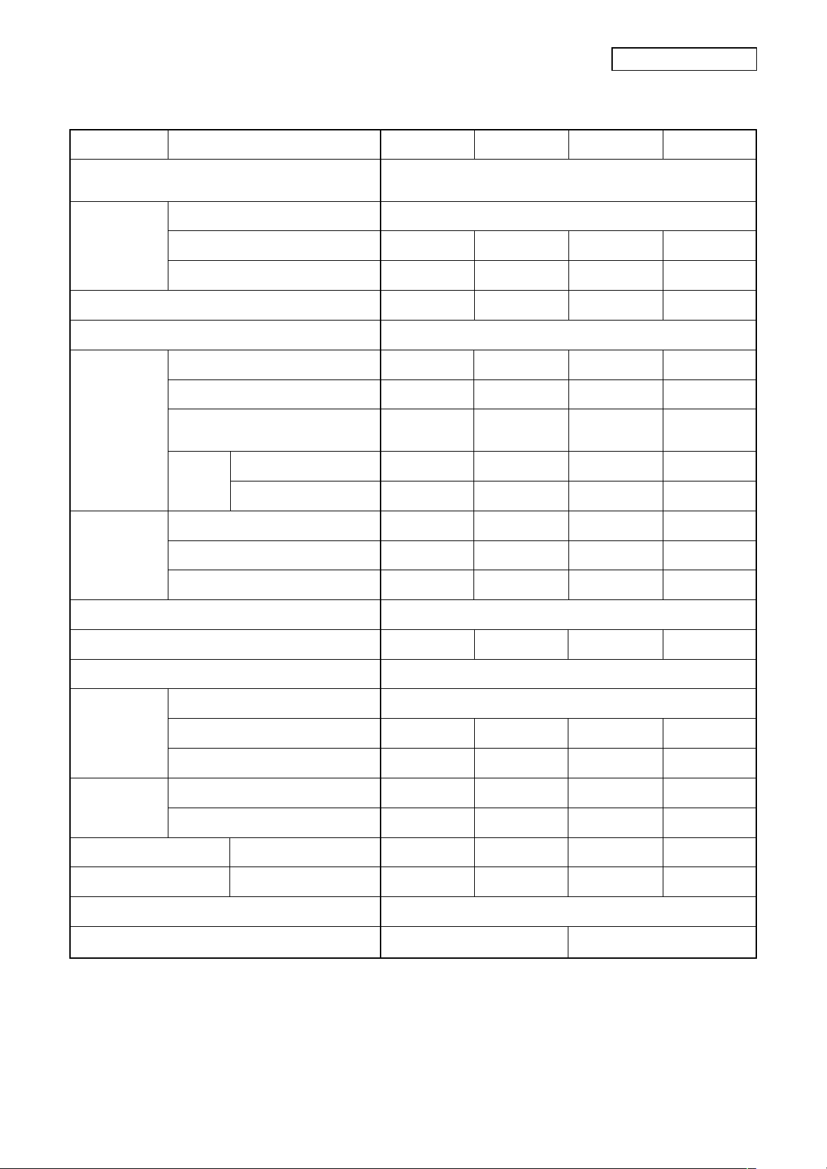
1-3. Operation Characteristic Curve
• Operation characteristic curve <Super Digital Inverter>
RAV-SP1104A T-E, RAV -SP1104ATZ-E, RAV-SP1104ATZG-E
RAV-SP1404A T-E, RAV-SP1404ATZ-E, RAV-SP1404ATZG-E
<Cooling> <Heating>
22
20
18
16
14
12
10
SP140
SP140
Current (A)
8
SP110
SP110
6
4
2
0
020406080
• Conditions
Indoor : DB27˚C/WB19˚C
Outdoor : DB35˚C
Air flow : High
Pipe length : 7.5m
230V
Compressor speed (rps)
22
20
SP110
18
16
14
12
10
SP110
SP140
SP140
Current (A)
8
6
4
2
0
020406080
• Conditions
Indoor : DB20˚C
Outdoor : DB7˚C/WB6˚C
Air flow : High
Pipe length : 7.5m
230V
Compressor speed (rps)
RAV-SP404A T-E, RAV-SP404ATZ-E, RAV-SP404ATZG-E
RAV-SP454AT-E, RAV-SP454ATZ-E, RAV-SP454ATZG-E
<Cooling> <Heating>
14
12
SP45
10
8
6
Current (A)
4
2
0
0 20 405060708090100
SP45
• Conditions
Indoor : DB27˚C/WB19˚C
Outdoor : DB35˚C
Air flow : High
Pipe length : 7.5m
230V
SP40
SP40
16
14
12
10
8
Current (A)
6
4
2
0
0 2040608090100120
SP40
SP40
SP45
SP45
• Conditions
Indoor : DB20˚C
Outdoor : DB7˚C/WB6˚C
Air flow : High
Pipe length : 7.5m
230V
Compressor speed (rps)
Compressor speed (rps)
– 27 –
Page 28
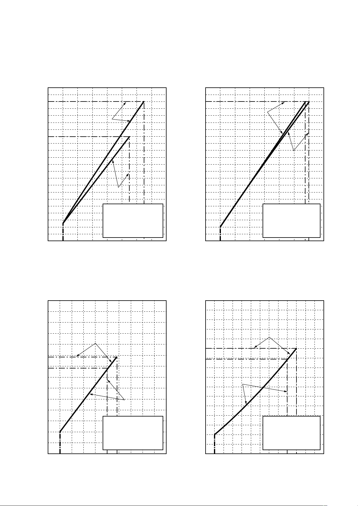
• Capacity variation ratio according to temperature
RAV-SP404A T-E, RAV-SP404ATZ-E, RAV-SP404ATZG-E
RAV-SP454AT-E, RAV-SP454ATZ-E, RAV-SP454ATZG-E
RAV-SP1104A T-E, RAV-SP1104ATZ-E, RAV-SP1104ATZG-E
RAV-SP1404A T-E, RAV-SP1404ATZ-E, RAV-SP1404ATZG-E
<Cooling> <Heating>
105
100
95
90
85
80
75
70
Capacity ratio (%)
65
60
55
50
32 33 34 35 36 37 38 39
Outdoor temp. (˚C)
• Conditions
Indoor : DB27˚C/WB19˚C
Indoor air flow : High
Pipe length : 7.5m
40
41 42 43
120
110
100
90
80
70
60
50
Capacity ratio (%)
40
30
20
10
0
-14-16-18-20 -12 -10 -8 -6 -4 -2 0 2 4 6 8 10
• Conditions
Indoor : DB20˚C
Indoor air flow : High
Pipe length : 7.5m
Outdoor temp. (˚C)
– 28 –
Page 29
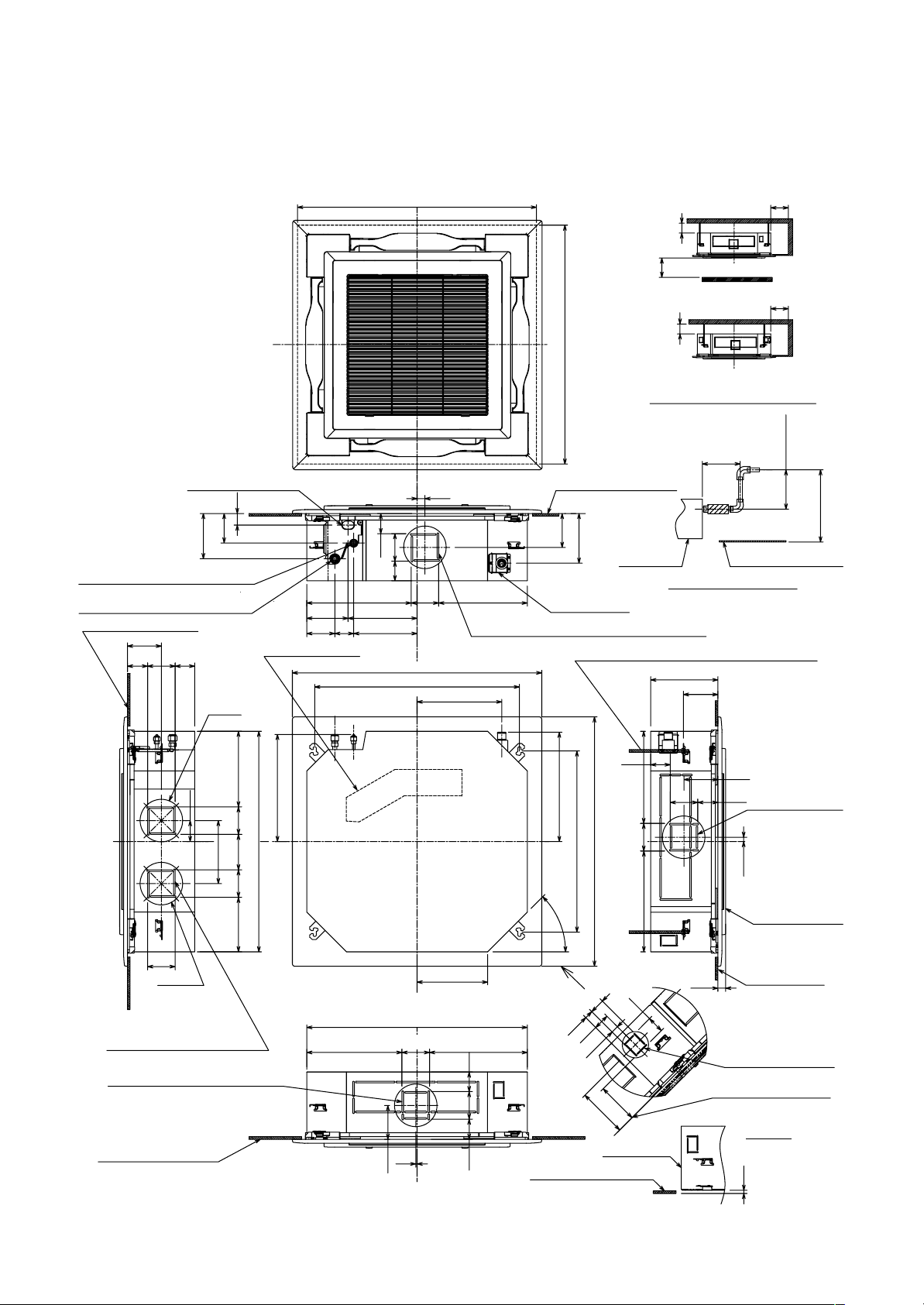
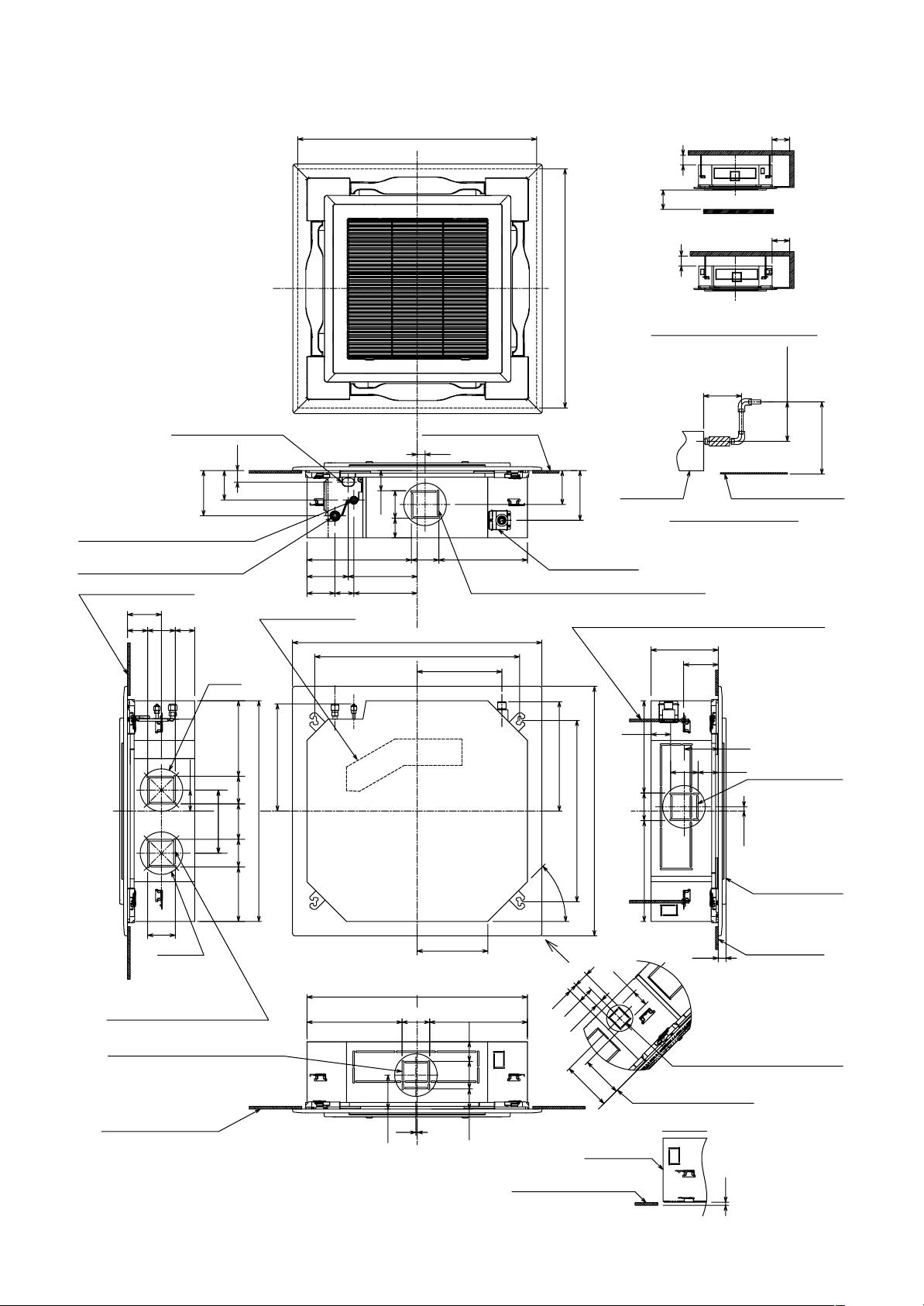
2-1. Indoor Unit
RAV-SM564UT-E
2. CONSTRUCTION VIEWS (EXTERNAL VIEWS)
860 to 910 Ceiling open dimension
15 or more
1000 or more
15 or more
The space that is necessary
for equipping and service
860 to 910 Ceiling open dimension
1000 or more
An obstacle
1000 or more
Take-in port of wiring
44
112
172
Refrigerant pipe connecting port
Ø6.4 (Liquid side)
Refrigerant pipe connecting port
Ø12.7 (Gas side)
Bottom face of ceiling
129
77
105 74
Ø162
80
240
Electric parts box
408
135105207.5 105 287.5
840 Unit external dimension
77
105
74
397.5
157
106.5
263
72 241.5
950 Panel external dimension
780 Hanging bolt pitch
30
105 337.5
For branch duct knockout square hole Ø150
323
300
Bottom face of ceiling
129
189
Drain pipe
connecting port
(Meterial : PP)
Hanging bolt M10 or Ø3/8(procured by locally)
74
416.5
690 ± 20 Hanging bolt pitch
45˚
950 Panel external dimension
Drain upstanding size
256
105 77
105
384 351
Bottom face of ceilingIndoor unit
132
129
16.5
Standing
661 or less
Standing
850 or less
For branch duct
knockout square
hole Ø150
Ceiling panel
(sold separately)
105
Ø162
For branch duct knockout
square hole Ø150
(2 positions)
For branch duct knockout
square hole Ø150
Bottom face of ceiling
269
840 Unit external dimension
362.5 105 372.5
7477
105
5
129
– 29 –
57
28.5
187
64
155
Indoor unit
Z
32
61
Bottom face of ceiling
Bottom face
29
of ceiling
Knockout for simple
0A for Ø100
Bottom face of ceiling
Z view
12
Unit : mm
Page 30
RAV-SM804UT-E
Take-in port of wiring Bottom face of ceiling
44
112
172
Refrigerant pipe connecting port
Ø9.5 (Liquid side)
Refrigerant pipe connecting port
Ø15.9 (Gas side)
Bottom face of ceiling
129
77
105 74
Ø162
860 to 910 Ceiling open dimension
157
106.5
72 241.5
Electric parts box
30
77
74 105
397.5
950 Panel external dimension
780 Hanging bolt pitch
105 337.5
263
For branch duct knockout square hole Ø150
323
1000 or more
15 or more
1000 or more
15 or more
1000 or more
The space that is necessary
for equipping and service
860 to 910 Ceiling open dimension
129
189
Drain pipe
connecting port
(Meterial : PP)
Hanging bolt M10 or Ø3/8 (procured by locally)
300
Bottom face of ceilingIndoor unit
Drain upstanding size
256
132
An obstacle
Standing
661 or less
Standing
850 or less
80
240
105
Ø162
For branch duct knockout
square hole Ø150
(2 positions)
For branch duct knockout
square hole Ø150
Bottom face of ceiling
408
135105207.5 105 287.5
840 Unit external dimension
269
840 Unit external dimension
362.5 105 372.5
7477
105
5
129
74
416.5
105
690 ± 20 Hanging bolt pitch
Z
45˚
32
61
950 Panel external dimension
57
28.5
187
Indoor unit
384 351
64
155
Bottom face of ceiling
129
For branch duct
105 77
29
Knockout for simple 0A for Ø100
knockout square
hole Ø150
16.5
Ceiling panel
(sold separately)
Bottom face
of ceiling
Z view
– 30 –
Bottom face of ceiling
12
Unit : mm
Page 31

RAV-SM1104UT-E, RAV-SM1404UT-E, RAV-SM1604UT-E
860 to 910 Ceiling open dimension
860 to 910 Ceiling open dimension
129
189
105
105384 351
137
16.5
77
129
132
319
29
397.5
157
106.5
72 241.5
263
105 337.5
Bottom face of ceiling
For branch duct
knockout square
hole Ø150
Ceiling panel
(sold separately)
Bottom face
of ceiling
80
240
135105207.5 105 287.5
840 Unit external dimension
77
129
105 137
Hanging bolt M10 or Ø3/8 (procured by locally)
For branch duct knockout square hole Ø150
Drain pipe
connecting port
(Meterial : PP)
77
137 105
30
Bottom face of ceiling
112
44
172
Take-in port of wiring
Refrigerant pipe connecting port
Ø9.5 (Liquid side)
Refrigerant pipe connecting port
Ø15.9 (Gas side)
For branch duct
knockout square hole Ø150
(2 positions)
An obstacle
Standing
850 or less
300
Standing
661 or less
The space that is necessary
for equipping and service
Drain upstanding size
1000 or more
1000 or more
15 or more
15 or more
1000 or more
Bottom face of ceilingIndoor unit
Unit : mm
Knockout for simple 0A for Ø100
Bottom face of ceiling
Bottom face of ceiling
Indoor unit
155
64
28.5
61
32
57
187
Z view
Z
Ø162
Ø162
105
950 Panel external dimension
780 Hanging bolt pitch
323
269
950 Panel external dimension
690 ± 20 Hanging bolt pitch
416.5
45˚
408
Electric parts box
840 Unit external dimension
362.5 105 372.5
105
137
For branch duct knockout
square hole Ø150
Bottom face of ceiling
77
129
5
Revised 2: Jun., 2008
– 31 –
Page 32

RAV-SM404SDT-E, RAV-SM454SDT-E, RAV-SM564SDT-E
Ø92
80
59
4-Ø4
80
21
168
(inside)
21
20
19
168
120
21
845
803 (inside)
Air filter
805
910
21
57
67
511
67
210
645
Refrigerant piping
103
31
33
163
40
359
372
422
502
Fresh air inlet
(knock-out hole)
Drain-up port
Hung-up plate
– 32 –
Page 33

365 17.5
17.5
Drain hole (Ø28 × 88)
128
118
74
Air inlet port
380
200 60
Air inlet
port
75
Air outlet
port
383
150 600
46
70
Drain hole (Ø25)
34
170
A legs
B legs
48
39
96
Mounting bolt hole
(Ø12 × 17 long hole)
54
40
40
Details of A legs Details of B legs
12
Name Note
Refrigerant piping hole
1
Indoor/Outdoor unit
connecting wire inlet hole
Power supply inlet hole Ø38 Kockout hole
2
Mounting bolt hole
(Ø12 × 17 U-shape hole)
——
2-2. Outdoor Unit
RAV-SP1104A T(Z)(ZG)-E, RAV-SP1404AT(Z)(ZG)-E
52
– 33 –
121 53453485
655
360
70 74581 581
60
68 518 135 151 12
83 7
178
327 400
900
550
Refrigerant pipe
connecting port
(Ø9.5 flare at liquid side)
Refrigerant pipe
connecting port
(Ø15.9 flare at gas side)
30
2
1
605
613
155
55 95
178 178 80 18 8018
2
1 1
95
55
94
320
1340
24
55 95
64
Z views
65 7
Knockout for downward piping
Z
Unit : mm
Page 34

RAVSP404AT(Z)(ZG)-E, RAV-SP454AT(Z)(ZG)-E
Drain hole
(2-Ø20 × 88 long hole)
69.5 147
320
306
Ø6 hole pitch
For anchor bolt)
(Long hole pitch
21
550
290
A legs
6
48335
30
B legs
44952
Drain hole (Ø25)
60
600
108 125
30
20
2-Ø11 × L14 long hole
(For Ø8-Ø10 anchor bolts)
483 257
108
90
2-Ø11-14 U-shape hole
54
(For Ø8-Ø10 anchor bolts)
Connecting pipe port
(Gas flare side: Ø12.7)
Connecting pipe port
(Liquid flare side: Ø6.4)
8-Ø6 hole
(For fixing outdoor unit)
25
22
157 79
21
145
31 143
8
Space required for service
2-Ø11 × 14 U-shape holes
(For Ø8–Ø10 anchor bolt)
32
500
780
Discharge guard
Discharge guide mounting hole
(4-Ø4.5 embossing)
600
Suction port
150
or more
150
or more
320
Discharge
port
500
or more
600
54
38
R15
3
320
Ø11 × 14 U-shape hole
Details of A legs Details of B legs
2-Ø6 hole
Product
external line
Discharge
port
Ø11 × 14 U-shape holes
320
3
137
93
71
300
or more
(Minimum
distance up to wall)
2-Ø11 × 14 long hole
(For Ø8–Ø10 anchor bolt)
2-Ø6 hole
Product
external
line
R15
38
54
600
Charge port
54
342
Earth
terminal
– 34 –
Page 35

RAV-TWP30E2, RAV-TWP50E2 (Simultaneous Twin)
Inner diameter Ø C
B
Inner
diameter Ø D
TWP30E2
TWP50E2
Model (RBC-)
Liquid side
Gas side
Liquid side
Gas side
Inner
diameter Ø D
A
ABCD
36 14 Ø9.5 Ø6.4
43 23 Ø15.9 Ø12.7
34 14 Ø9.5 Ø9.5
44 21 Ø15.9 Ø15.9
– 35 –
Page 36

3. SYSTEMATIC REFRIGERATING CYCLE DIAGRAM
3-1. Indoor Unit
• Single type (Combination of 1 indoor unit and 1 outdoor unit)
Revised 2: Jun., 2008
Distributor
(Strainer incorporated)
TC sensor
Refrigerant pipe
at liquid side
(Outer dia : ØB)
To outdoor unit
Dimension table
Indoor unit
SM80, 110, 140, 160
type
(Indoor unit)
TCJ sensor
Air heat
exchanger
Outer diameter of refrigerant pipe
Gas side ØA Liquid side ØB
15.9 9.5
Strainer
Refrigerant pipe
at gas side
(Outer dia : ØA)
To outdoor unit
Heating
Cooling
Capillary tube specifications
Model
RAV-SM∗∗∗UT
SM56 type
SM80 type
SM110, 140 , 160
type
Model
RAV-SM∗∗∗SDT
SM40, 45, 56 type
Inner dia. × Length × Q’ty
Ø2 × 250 × 2, Ø2 × 350 × 1
Ø2 × 700 × 1
Ø2 × 250 × 3, Ø2 × 500 × 1
Ø2 × 200 × 1, Ø2 × 300 × 2
Ø2 × 350 × 2, Ø2 × 700 × 1
Inner dia. × Length × Q’ty
Ø2 × 200 × 2, Ø2 × 350 × 1
• Twin type (Combination of 2 indoor units and 1 outdoor unit)
Distributor
(Strainer incorporated)
TC sensor
Refrigerant pipe
at liquid side
(Outer dia : ØA)
Branch pipe
To outdoor unit
Indoor unit
SM56 × 2
SM80 × 2
(Indoor unit A)
TCJ sensor
Air heat
exchanger
Refrigerant pipe
at gas side
(Outer dia : ØB)
Refrigerant pipe
at liquid side
(Outer dia : ØC)
Branch pipe RBC-
TWP30E2
TWP50E2
Distributor
(Strainer incorporated)
Strainer
TC sensor
Refrigerant pipe
at liquid side
(Outer dia : ØA)
Branch pipe
ABCD
6.4 12.7 9.5 15.9
9.5 15.9 9.5 15.9
(Indoor unit B)
TCJ sensor
Air heat
exchanger
Refrigerant pipe
at liquid side
(Outer dia : ØD)
To outdoor unit
Heating
Cooling
Strainer
Refrigerant pipe
at gas side
(Outer dia : ØB)
– 36 –
Page 37

3-2. Outdoor Unit
RAV-SP1104AT-E, SP1104ATZ-E, SP1104ATZG-E, RAV-SP1404AT-E, SP1404ATZ-E, SP1404ATZG-E
Accumulator
(2500cc)
TS sensor
Check joint
Cooling: High pressure
Heating: Low pressure
TD sensor
Rotary compressor
(DA422A3F-25M)
MufflerMuffler
Ø25 × L210
TO sensor
TL sensor
Heat exchanger
Ø8, 2 rows, 52 stages
FP1.45, flat fin
In cooling operation
In heating operation
Ø25 × L180
TE sensor
Distributor
Strainer
PMV
Strainer
Capillary
Ø4 ×Ø3 (6 pcs.)
Refrigerant pipe
at liquid side Ø9.5
Packed valve
Refrigerant pipe
at gas side Ø15.9
Ball valve
Cooling: Low pressure
Heating: High pressure
RAV-SP1104A T-E, RAV-SP1104ATZ-E, RAV-SP1104ATZG-E
Pressure
(MPa) (kg/cm²g)
Pd Ps Pd Ps
Standard
Cooling Overload
Low load
Standard
Heating Overload
Low load
This compressor has 4-pole motor. The value when compressor frequency (Hz) is measured by a clamp
*
meter becomes 2 times of No. of compressor revolutions (rps).
2.57 0.99 26.2 10.1
3.30 1.09 33.7 11.1
1.74 0.75 17.8 7.7
2.32 0.73 23.7 7.4
3.22 1.17 32.9 11.9
2.17 0.30 22.1 3.1
Discharge Suction
Pipe surface temperature (°C)
Indoor heat Outdoor heat
exchanger exchanger
(TD) (TS) (TC) (TL) (TE)
66 14 12 44 38
78 9 13 49 43
46 7 5 32 25
65 3 39 2 3
73 19 54 14 15
87 –15 38 –14 –13
Compressor
drive revolution
frequency
(rps)
38
53
21
43
26
71
Indoor
fan
HIGH
HIGH
LOW
HIGH
LOW
HIGH
Indoor/Outdoor
temp. conditions
(DB/WB) (°C)
Indoor Outdoor
27/19 35/–
32/24 43/–
18/15.5 –5/–
20/– 7/6
30/– 24/18
15/––15/–
RAV-SP1404A T-E, RAV-SP1404ATZ-E, RAV-SP1404ATZG-E
Standard
Cooling Overload
Low load
Standard
Heating Overload
Low load
Pressure
(MPa) (kg/cm²g)
Pd Ps Pd Ps
2.72 0.90 27.8 9.2
3.34 1.07 34.1 10.9
1.75 0.76 17.9 7.8
2.59 0.69 26.4 7.0
3.13 1.05 31.9 10.7
2.40 0.21 24.5 2.1
Discharge Suction
Pipe surface temperature (°C)
Indoor heat Outdoor heat
exchanger exchanger
(TD) (TS) (TC) (TL) (TE)
73 12 10 46 38
80 9 13 51 45
47 8 6 33 25
75 3 43 2 2
72 16 53 12 13
97 –22 42 –19 –18
Compressor
drive revolution
frequency
(rps)
51
55
21
53
26
90
Indoor
fan
HIGH
HIGH
LOW
HIGH
LOW
HIGH
Indoor/Outdoor
temp. conditions
(DB/WB) (°C)
Indoor Outdoor
27/19 35/–
32/24 43/–
18/15.5 –5/–
20/– 7/6
30/– 24/18
15/––15/–
This compressor has 4-pole motor. The value when compressor frequency (Hz) is measured by a clamp
*
meter becomes two times of No. of compressor revolutions (rps).
– 37 –
Page 38

RAV-SP404AT-E, RAV-SP404ATZ-E, RAV-SP404ATZG-E
RAV-SP454AT-E, RAV-SP454ATZ-E, RAV-SP454ATZG-E
Revised 2: Jun., 2008
TS sensor
TD sensor
4-way valve
(STF-0108Z)
Rotary compressor
(DA150A1F-20F)
2-step muffler
Ø19.05 × 200L
Muffler
Ø19 × L160
Packed valve
Outer dia. ØA
TO sensor
Heat exchanger
Ø8 ripple, 2 rows,
14 steps
FP1.3 flat fin
Packed valve
Outer dia. ØB
PMV
(Pulse Motor Valve)
(CAM-B30YGTF-2)
Strainer
TE
sensor
Distributor
R410A 1.0 kg
Cooling
Heating
RAV-SP404AT-E, RAV-SP404ATZ-E, RAV-SP404ATZG-E
Pressure
(MPa) (kg/cm²g)
Pd Ps Pd Ps
Standard
Cooling Overload
Low load
Standard
Heating Overload
Low load
This compressor has 4-pole motor. The value when compressor frequency (Hz) is measured by a clamp
*
meter becomes 2 times of No. of compressor revolutions (rps).
2.68 0.94 27.3 9.6
3.23 1.16 32.9 11.8
1.34 0.70 13.7 7.1
2.38 0.70 24.3 7.1
3.39 1.03 34.6 10.5
1.95 0.26 19.9 2.7
Discharge Suction
Pipe surface temperature (°C)
Indoor heat Outdoor heat
exchanger exchanger
(TD) (TS) (TC) (TE)
61 12 11 43
77 14 15 50
36 4 2 8
65 7 39 4
83 20 54 16
90 –17 32 –19
Compressor
drive revolution
frequency
(rps)
47
50
44
49
49
90
Indoor
fan
HIGH
HIGH
LOW
HIGH
LOW
HIGH
Indoor/Outdoor
temp. conditions
(DB/WB) (°C)
Indoor Outdoor
27/19 35/–
32/24 43/–
18/15.5 –5/–
20/– 7/6
30/– 24/18
15/––15/–
RAV-SP454AT-E, RAV-SP454ATZ-E, RAV-SP454ATZG-E
Standard
Cooling Overload
Low load
Standard
Heating Overload
Low load
Pressure
(MPa) (kg/cm²g)
Pd Ps Pd Ps
2.81 0.89 28.7 9.1
3.24 1.16 33.0 11.8
1.34 0.70 13.7 7.1
2.53 0.68 25.8 6.9
3.39 1.03 34.6 10.5
2.00 0.25 20.4 2.6
Discharge Suction
Pipe surface temperature (°C)
Indoor heat Outdoor heat
exchanger exchanger
(TD) (TS) (TC) (TE)
68 11 10 41
78 14 15 51
36 4 2 8
70 7 41 4
83 20 54 16
92 –17 33 –19
Compressor
drive revolution
frequency
(rps)
53
53
44
56
49
98
Indoor
fan
HIGH
HIGH
LOW
HIGH
LOW
HIGH
Indoor/Outdoor
temp. conditions
(DB/WB) (°C)
Indoor Outdoor
27/19 35/–
32/24 43/–
18/15.5 –5/–
20/– 7/6
30/– 24/18
15/––15/–
This compressor has 4-pole motor. The value when compressor frequency (Hz) is measured by a clamp
*
meter becomes two times of No. of compressor revolutions (rps).
– 38 –
Page 39

4. FAN CHARACTERISTICS
4-1. Slim Duct (Filter Attached)
RAV-SM404SDT-E, RAV-SM454SDT-E
60
Upper limit of external
static pressure(50Pa)
50
Upper limit of
external static
pressure(35Pa)
40
Upper limit of
30
external static
pressure
(20Pa)
20
Low (50Pa)
Low (35Pa)
External static pressure(Pa)
Upper limit of
external static
pressure(10Pa)
10
Low (10Pa)
0
400
500 600 700 800
Air volume (m³/h)
Low (20Pa)
Standard air volume : 690m³/h
High (50Pa)
High
(35Pa)
Standard filte
pressure loss
High
(20Pa)
High
(10Pa)
Lower limit of
external static
pressure (50Pa)
Lower limit of
external static
pressure (35Pa)
Lower limit of
external static
pressure (20Pa)
RAV-SM564SDT-E
60
Upper limit of external
static pressure(50Pa)
50
Upper limit of
external static
pressure(35Pa)
40
30
Upper limit of
external static
pressure
(20Pa)
20
External static pressure(Pa)
Upper limit of
external static
pressure(10Pa)
10
Low (10Pa)
0
400
500 600 700 900800
Air volume (m³/h)
Low (50Pa)
Low (35Pa)
Low (20Pa)
Standard filte
pressure loss
Standard air volume : 780m³/h
High (50Pa)
Lower limit of
external static
High
(35Pa)
High
(10Pa)
pressure (50Pa)
Lower limit of
external static
pressure (35Pa)
High
(20Pa)
Lower limit of
external static
pressure (20Pa)
– 39 –
Page 40

Revised 2: Jun., 2008
5. WIRING DIAGRAM
5-1. Indoor Unit
5-1-1. 4-Way Air Discharge Cassette Type
RAV-SM564UT-E, RAV-SM804UT-E, RAV-SM1104UT-E, RAV-SM1404UT-E, RAV-SM1604UT-E
LM1 LM3 LM2 LM4
FM
1 2 3 4 5 1 2 3 4 5 1 2 3 4 5 1 2 3 4 5
1 2 3 4 5 1 2 3 4 5 1 2 3 4 5 1 2 3 4 5
Indoor unit
earth screw
NL
2 31
2 31
RED
WHI
BLK
Serial
signal
1 3 5
1 3
3
3
CN334
2
2
(WHI)
1
1
Fuse, F01
T6.3A, 250V~
1
1
3
3
CN67
(BLK)
5
5
P01
BLK
1
CN66
2
(WHI)
remote controller
(BLU)
CN333
(WHI)
5 6 7 8 9 10 11 12 13 14 15 16 17 18 19 20
1 2 3 1 2 1 2
1 2 3 1 2 1 2 34 5
(WHI)
(RED)
CN510
(WHI)
Motor drive
circuit
Fuse, F02
T3.15A, 250V~
~
~
+
–
Control P.C. Board
for Indoor Unit
MCC-1570
CN41
(BLU)
CN32
(T10)
CN61
(YEL)
(WHI)
(Fan drive)
CN309
(YEL)
31
BLKBLK
CN60
(WHI)
21
BA
21
A B
Wired
wireless remote controller
21
CN001
(WHI)
Adapter for
(BLK)
Power
supply
circuit
DC20V
DC15V
DC12V
DC7V
CN50
(WHI)
5 643215 6432131321
CN51
(RED)
321
P.C. board
MCC-1440
Terminal
for central
U3 U4
remote controller
Connection interface
(Option)
DM
CN504
(WHI)
54321
54321
54321
54
21
21
CN34
(RED)
CN104
(YEL)
CN102
(RED)
CN101
(BLK)
CN519
(WHI)
CN508
(RED)
CN80
(GRN)
CN73
(RED)
CN70
(WHI)
CN20
(BLU)
FS
34 5 6 7 8 9 10 11 12 13 14 15 16 17 18 19 20
1 1
2 2
TA
1 1
2 2
TCJ
1 1
2
2
TC
1
2
3
4
1
2
1
2
3
1
(EXCT)
2
1
2
54321
Signal phase
220–240V~, 50Hz
Outdoor unit
Outdoor unit
earth screw
Color
Identification
BLK : BLACK
BLU : BLUE
RED : RED
GRN : GREEN
WHI : WHITE
YEL : YELLOW
– 40 –
Symbol
FM
TA
TC, TCJ
LM1, LM2, LM3, LM4
DM
FS
Parts name
Fan Motor
Indoor temp. sensor
Temp. sensor
Louver motor
Drain pump Motor
Float Switch
Page 41

5-1-2. Slim Duct Type
RAV-SM404SDT-E, RAV-SM454SDT-E, RAV-SM564SDT-E
FM
DM
FS
Indoor unit
earth screw
2 31
2 31
NL
RED
WHI
BLK
Serial
signal
1 3 5
1 3
3
3
CN334
2
2
(WHI)
1
1
Fuse, F01
T6.3A, 250V~
1
1
3
3
CN67
(BLK)
5
5
P01
BLK
1
CN66
2
(WHI)
remote controller
CN333
(WHI)
5 6 7 8 9 10 11 12 13 14 15 16 17 18 19 20
1 2 3 1 2 1 2 34 5
CN510
(WHI)
Motor drive
circuit
Fuse, F02
T3.15A, 250V~
~
~
+
–
Control P.C. Board
for Indoor Unit
MCC-1570
CN41
(BLU)
CN32
(T10)
CN61
(YEL)
(WHI)
21
(Fan drive)
CN309
(YEL)
31
BLKBLK
CN60
(WHI)
BA
21
A B
Wired
wireless remote controller
21
CN001
(WHI)
Adapter for
Power
supply
circuit
DC20V
DC15V
DC12V
DC7V
CN50
(WHI)
5 643215 6432131321
CN51
(RED)
54321
54321
54321
54
321
P.C. board
MCC-1440
21
21
Terminal
for central
U3 U4
remote controller
Connection interface
(Option)
1 2 1 2
CN504
(WHI)
CN34
(RED)
CN104
(YEL)
CN102
(RED)
CN101
(BLK)
CN519
(WHI)
CN508
(RED)
CN80
(GRN)
CN73
(RED)
CN70
(WHI)
CN20
(BLU)
3
1 1
2 2
TA
1 1
2 2
TCJ
1 1
2
2
TC
1
2
3
4
1
2
1
2
3
1
(EXCT)
2
1
2
54321
Signal phase
220–240V~, 50Hz
Outdoor unit
Outdoor unit
earth screw
Color
Identification
BLK : BLACK
BLU : BLUE
RED : RED
GRN : GREEN
WHI : WHITE
YEL : YELLOW
– 41 –
Symbol
FM
TA
TC, TCJ
DM
FS
Parts name
Fan Motor
Indoor temp. sensor
Temp. sensor
Drain pump Motor
Float Switch
Page 42

5-2. Outdoor Unit
RAV-SP1104AT-E, SP1104ATZ-E, 1104ATZG-E
RAV-SP1404AT-E, SP1404ATZ-E, 1404ATZG-E
Reactor Reactor
(GRY) (GRY) (WHI) U(WHI)
CM
(RED) (WHI) (BLK)
V W
FM01
FM02
TL
TD
TO
TE
49C
1 1
2 2
1 1
2 2
1 1
2 2
1 1
2 2
1 1
3 3
1 1
2 2
1 1
2 2
33
33
1
2
3
4
5
6
2
CN400
(WHI)
CN300
(WHI)
CN609
(BLU)
CN610
(YEL)
CN604
(WHI)
CN603
(WHI)
CN602
(YEL)
CN601
(WHI)
P04 P05 P06 P07
SW804 SW801 SW800
2 3 4
1
ON
Control P.C. Board
SW803
ON
ON
SW802
2 3 4
2 3 41
1
MCC-1570
RY704
CN201 CN202CN200
L/F
Fuse, F01
T25A, 250V~
(BLK)
P09
Fuse, F03
T10A, 250V~
1 1
CN600
TS
Symbol
CM
FM01, 02
PMV
TD
TS
TE
TL
TO
20SF
49C
RY
L/F
2
(WHI)
3 3
CN710
(WHI)
Discharge pipe temp. sensor
Suction pipe temp. sensor
Heat exchanger temp. sensor 1
Heat exchanger temp. sensor 2
Compressor case thermostat
1 2 3 4 5 6
1 2 3
Parts name
Compressor
Fan Motor
Pulse Motor Valve
Outside temp. sensor
4-way valve coil
Relay
Line Filter
CN704
(BLU)
1 341 4
Outdoor unit
Indoor unit
CN701
(WHI)
1 4
20SFPMW
Earth
screw
Earth
screw
CN04
(WHI)
1 7
(GRY)
1. indicates the terminal block.
Alphanumeric characters in the cycle indicate the terminal No.
2. The two-dot chain line indicates the wiring procured locally.
3. indicates the P.C. board.
4. For the indoor unit circuit, refer to the wiring diagram of the indoor unit.
3 5
(WHI)
1 2 3
53
(RED)
P02P01
716
(RED) (WHI)
(BLK)
Earth
screw
L N1 2 3
Power supply
220–240V~, 50Hz
Color
Identification
BLK : BLACK
BLU : BLUE
RED : RED
GRY : GRAY
WHI : WHITE
YEL : YELLOW
– 42 –
Page 43

RAV-SP404AT-E, RAV-SP404ATZ-E, RAV-SP404ATZG-E
RAV-SP454AT-E, RAV-SP454ATZ-E, RAV-SP454ATZG-E
ORN
CN500
Compressor
RED
WHI
BLK
P25
P24
P23
P22
P21
P20
P35
P34
P19
P18
P11
P08
P04
P05
P06
DB01
Q404
1
3
1
RED
WHI
BLK
223
1
3
1
SW802
MCC-1530
Sub P.C. Board
BLK
Q200~205
IGBT
Power
relay
DB02
R221
R220
R219
L03 C13
CT
Relay
PUR
P.C. Board
(MCC-5009)
F03
Fuse
T3.15A
AC250V
C12 C14
112
2
Reactor
CN701
Q300~305
MOS-FET
R321
R320
R319
Varistor
L01
Surge
absorber
Varistor
F01
Fuse
T25A
AC250V
P03
P10
ORN
WHI
BLK
ORN
RED
P7P32P33
3
1
1
3
BLKP30P31CN605
Coil for
4-WAY
VALVE
Fuse 250V~
T6.3A
Reactor
RED
1
CM
212
3 3
YEL
YEL
BRN
CAUTION : HIGH VOLTAGE
The high voltage circuit is
incorporated.
Be careful to do the check service,
as the electric shock may be
caused in case of touching
parts on the
P.C. board by hand
YEL
– 43 –
The 4-way valve coil is turned on
while the cooling operation
NOTE
CM : Compressor
PMV : Pulse Motor Valve
FM : Fan Motor
TE : Heat Exchanger Temp. Sensor
Reactor
ORN
212
1
CN300
CN700
For optional P.C. Board
WHI
BLK
WHI
212
3
2
1
6
5
4
3
2
1
CN603
CN602
CN601
CN600
P02
WHI CN806
GRN/YEL
ORN
1
BLK
3
WHI
2
RED
1
6
5
4
3
2
1
4 52 31223
49C
FM
Fan motor
PMV
Pulse motor valve
3
2
131
(Suction pipe
1
1
temp. sensor)
(Outdoor
temp. sensor)
(Discharge pipe
temp. sensor)
(Condenser pipe
temp. sensor)
212
3
2
131
212
TS
TO
TD
TE
TD : Discharge Temp . Sensor
TO : Outdoor T emp . Sensor
TS : Suction Temp. Sensor
IGBT: Insulated Gate Bipolar Transistor
DB : Rectifier
CT : Curreut Transf ormer
49C : Compressor Case Thermostat
Color Identification
BLK
:
BLACK
BLU
:
BLUE
RED
:
RED
GRY
:
GRAY
PNK
:
PINK
WHI
BRN
ORN
YEL
PUR
:
WHITE
:
BROWN
:
ORANGE
:
YELLOW
:
PURPLE
To indoor Power supply
NL321
220-240V~ 50Hz
Page 44

6. SPECIFICATIONS OF ELECTRICAL PARTS
6-1. Indoor Unit
RAV-SM564UT-E, RAV-SM804UT-E
Revised 2: Jun., 2008
No.
1
Fan motor (for indoor)
2
Thermo. sensor (TA-sensor)
3
Heat exchanger sensor (TCJ-sensor)
4
Heat exchanger sensor (TC-sensor)
5
Float switch
6
Drain pump motor
Parts name
RAV-SM1104UT-E, RAV-SM1404UT-E, RAV-SM1604UT-E
No.
1
Fan motor
2
Thermo. sensor (TA-sensor)
3
Heat exchanger sensor (TCJ-sensor)
4
Heat exchanger sensor (TC-sensor)
5
Float switch
6
Drain pump motor
Parts name
Type
SWF-230-60-2R
328 mm
Ø6 mm, 1000 mm
Ø6 mm, 950 mm
FS-0218-102
MDP-1401
Type
ICF-280-150-1
328 mm
Ø6 mm, 1000 mm
Ø6 mm, 950 mm
FS-0218-102
MDP-1401
Specifications
Output (Rated) 60 W
10 kΩ at 25°C
10 kΩ at 25°C
10 kΩ at 25°C
—
—
Specifications
Output (Rated) 90 W
10 kΩ at 25°C
10 kΩ at 25°C
10 kΩ at 25°C
—
—
RAV-SM404SDT-E, RAV-SM454SDT-E, RAV-SM564SDT-E
No.
1
Fan motor
2
Drain pump motor
3
Float switch
4
TA sensor
5
TC sensor
6
TCJ sensor
Parts name
Lead wire length : 328mm
Ø6 size lead wire length : 1200mm Vinyl tube (Black)
Ø6 size lead wire length : 1200mm Vinyl tube (Red)
Type
SWF-280-60-3
MDP-1401
FS-0218-102
Specifications
—
—
—
10 kΩ at 25°C
10 kΩ at 25°C
10 kΩ at 25°C
– 44 –
Page 45

6-2. Outdoor Unit (Parts Ratings)
RAV-SP1104A T-E, RAV-SP1104ATZ-E, RAV-SP1104ATZG-E
RAV-SP1404A T-E, RAV-SP1404ATZ-E, RAV-SP1404ATZG-E
Revised 2: Jun., 2008
No.
1
Compressor
2
Outdoor fan motor
3
Reactor
4
4-way valve coil
5
PMV coil
6
P.C. board
7
Fuse (Mounted on P.C. board)
8
Fuse (Mounted on P.C. board)
9
Fuse (Mounted on P.C. board)
10
Outdoor temp. sensor (TO sensor)
11
Heat exchanger sensor (Te sensor)
12
Discharge temp. sensor (Td sensor)
13
Heat exchanger mid. Temp sensor (TL sensor)
14
Compressor thermo. (Protection)
Parts name
DA422A3F-25M
ICF-280-A100-1
VHV-01AP552B1
RAV-SP404AT-E, RAV-SP404ATZ-E, RAV-SP404ATZG-E
RAV-SP454AT-E, RAV-SP454ATZ-E, RAV-SP454ATZG-E
Type
CH-62
UKV-A038
MCC-1571
—
—
—
—
—
—
—
US-622
Specifications
—
Output 100W
5.7mH, 18.5A
AC240V
DC12V
AC220 – 240V
AC250V, 25A
AC250V, 10A
AC250V, 3.15A
10 kΩ at 25°C
10 kΩ at 25°C
50 kΩ at 25°C
10 kΩ at 25°C
OFF: 125 ± 4°C, ON: 90 ± 5°C
No.
1
Fan motor
2
Compressor
3
Reactor
4
Outdoor temp. sensor (To sensor)
5
Heat exchanger sensor (Te sensor)
6
Suction temp. sensor (Ts sensor)
7
Discharge temp. sensor (Td sensor)
8
Fuse (Switching power (Protect))
9
Fuse (Inverter, input (Current protect))
10
4-way valve solenoid coil
11
Compressor thermo. (Protection)
12
Coil (Pulse Motor Valve)
Parts name
Type
ICF-140-43-4R
DA150A1F-20F
CH-57
—
—
—
—
—
—
STF-01AJ502E1
US-622
CAM-MD12TF-6
Specifications
Output (Rated) 43W
3 phase, 4P, 1100W
10mH, 16A
10 kΩ at 25°C
10 kΩ at 25°C
10 kΩ at 25°C
50 kΩ at 25°C
T3.15A, AC 250V
AC240V
—
OFF: 125 ± 4°C, ON: 90 ± 5°C
—
6-3. Accessory Separate Sold Parts
RBC-U31PG (W, WS)-E (Ceiling panel), RBC-U31PGS (W, WS)-E (Ceiling panel)
RAV-SM564UT-E, RAV-SM804UT-E, RAV-SM1104UT-E, RAV-SM1404UT-E, RAV-SM1604UT-E
No.
1
2
Motor-louver
Parts name
– 45 –
Type
MP24ZN3N
Specifications
DC 12 V
Page 46

7. REFRIGERANT R410A
This air conditioner adopts the new refrigerant HFC
(R410A) which does not damage the ozone layer.
The working pressure of the new refrigerant R410A
is 1.6 times higher than conventional refrigerant
(R22). The refrigerating oil is also changed in
accordance with change of refrigerant, so be careful
that water, dust, and existing refrigerant or
refrigerating oil are not entered in the refrigerant
cycle of the air conditioner using the new refrigerant
during installation work or servicing time.
The next section describes the precautions for air
conditioner using the new refrigerant.
Conforming to contents of the next section together
with the general cautions included in this manual,
perform the correct and safe work.
7-1. Safety During Installation/Servicing
As R410A’s pressure is about 1.6 times higher than
that of R22, improper installation/servicing may
cause a serious trouble. By using tools and
materials exclusive for R410A, it is necessar y to
carry out installation/servicing safely while taking
the following precautions into consideration.
1. Never use refrigerant other than R410A in an air
conditioner which is designed to operate with
R410A.
If other refrigerant than R410A is mixed,
pressure in the refrigeration cycle becomes
abnormally high, and it may cause personal
injury, etc. by a rupture.
2. Confirm the used refrigerant name, and use
tools and materials exclusive for the refrigerant
R410A.
The refrigerant name R410A is indicated on the
visible place of the outdoor unit of the air
conditioner using R410A as refrigerant.
To prevent mischarging, the diameter of the
service port differs from that of R22.
3. If a refrigeration gas leakage occurs during
installation/servicing, be sure to ventilate fully.
If the refrigerant gas comes into contact with fire,
a poisonous gas may occur.
4. When installing or removing an air conditioner,
do not allow air or moisture to remain in the
refrigeration cycle.
Otherwise, pressure in the refrigeration cycle
may become abnormally high so that a rupture
or personal injury may be caused.
5. After completion of installation work, check to
make sure that there is no refrigeration gas
leakage.
If the refrigerant gas leaks into the room, coming
into contact with fire in the fan-driven heater,
space heater, etc., a poisonous gas may occur.
6. When an air conditioning system charged with a
large volume of refrigerant is installed in a small
room, it is necessary to exercise care so that,
even when refrigerant leaks, its concentration
does not exceed the marginal level.
If the refrigerant gas leakage occurs and its
concentration exceeds the marginal level, an
oxygen starvation accident may result.
7. Be sure to carry out installation or removal
according to the installation manual.
Improper installation may cause refrigeration
trouble, water leakage, electric shock, fire, etc.
8. Unauthor ized modifications to the air conditioner
may be dangerous. If a breakdown occurs
please call a qualified air conditioner technician
or electrician.
Improper repair may result in water leakage,
electric shock and fire, etc.
7-2. Refrigerant Piping Installation
7-2-1. Piping Materials and Joints Used
For the refrigerant piping installation, copper pipes
and joints are mainly used.
Copper pipes and joints suitable for the refrigerant
must be chosen and installed.
Further more, it is necessary to use clean copper
pipes and joints whose interior surfaces are less
affected by contaminants.
1. Copper Pipes
It is necessary to use seamless copper pipes
which are made of either copper or copper alloy
and it is desirable that the amount of residual oil
is less than 40 mg/10 m.
Do not use copper pipes having a collapsed,
deformed or discolored portion (especially on
the interior surface).
Otherwise, the expansion valve or capillary tube
may become blocked with contaminants.
As an air conditioner using R410A incurs pressure higher than when using R22, it is necessary
to choose adequate materials.
Thicknesses of copper pipes used with R410A
are as shown in Table 7-2-1. Never use copper
pipes thinner than 0.8mm even when it is available on the market.
NOTE:
Refer to the “7-6. Instructions for Re-use Piping
of R22 or R407C”.
– 46 –
Page 47

Table 7-2-1 Thicknesses of annealed copper pipes
Thickness (mm)
Nominal diameter
1/4
3/8
1/2
5/8
1. Joints
For copper pipes, flare joints or socket joints are used. Prior to use, be sure to remove all contaminants.
a) Flare Joints
Flare joints used to connect the copper pipes cannot be used for pipings whose outer diameter exceeds
20 mm. In such a case, socket joints can be used.
Sizes of flare pipe ends, flare joint ends and flare nuts are as shown in Tables 7-2-3 to 7-2-5 below.
b) Socket Joints
Socket joints are such that they are brazed for connections, and used mainly for thick pipings whose
diameter is larger than 20 mm. Thicknesses of socket joints are as shown in Table 7-2-2.
Outer diameter (mm)
6.4
9.5
12.7
15.9
Table 7-2-2 Minimum thicknesses of socket joints
R410A R22
0.80 0.80
0.80 0.80
0.80 0.80
1.00 1.00
Nominal diameter
1/4
3/8
1/2
5/8
Reference outer diameter of
copper pipe jointed (mm)
6.4
9.5
12.7
15.9
Minimum joint thickness
(mm)
0.50
0.60
0.70
0.80
7-2-2. Processing of Piping Materials
When performing the refrigerant piping installation, care should be taken to ensure that water or dust does not
enter the pipe interior, that no other oil other than lubricating oils used in the installed air conditioner is used,
and that refrigerant does not leak. When using lubricating oils in the piping processing, use such lubricating
oils whose water content has been removed. When stored, be sure to seal the container with an airtight cap or
any other cover.
1. Flare Processing Procedures and Precautions
a) Cutting the Pipe
By means of a pipe cutter, slowly cut the pipe so that it is not deformed.
b) Removing Burrs and Chips
If the flared section has chips or burrs, refrigerant leakage may occur.
Carefully remove all burrs and clean the cut surface before installation.
– 47 –
Page 48

c) Insertion of Flare Nut
d) Flare Processing
Make certain that a clamp bar and copper pipe have been cleaned.
By means of the clamp bar, perform the flare processing correctly.
Use either a flare tool for R410A or conventional flare tool.
Flare processing dimensions differ according
to the type of flare tool.
When using a conventional flare tool, be sure
to secure “dimension A” by using a gauge for
size adjustment.
Table 7-2-3 Dimensions related to flare processing for R410A / R22
Nominal
diameter
Outer
diameter
(mm)
Thickness
(mm)
Flare tool for
R410A, R22
clutch type
Conventional flare tool
Clutch type Wing nut type
ØD
A
Fig. 7-2-1 Flare processing dimensions
A (mm)
Conventional flare tool
(R410A)
Clutch type Wing nut type
(R22)
1/4
3/8
1/2
5/8
Nominal
diameter
1/4
3/8
1/2
5/8
6.4
9.5
12.7
15.9
Outer diameter
(mm)
6.4
9.5
12.7
15.9
0.8
0.8
0.8
1.0
0 to 0.5
0 to 0.5
0 to 0.5
0 to 0.5
1.0 to 1.5 1.5 to 2.0
1.0 to 1.5 1.5 to 2.0
1.0 to 1.5 2.0 to 2.5
1.0 to 1.5 2.0 to 2.5
Table 7-2-4 Flare and flare nut dimensions for R410A
Thickness
(mm)
0.8
0.8
0.8
1.0
ABCD
9.1 9.2 6.5 13 17
13.2 13.5 9.7 20 22
16.6 16.0 12.9 23 26
19.7 19.0 16.0 25 29
Dimension (mm)
0.5 to 1.0 1.0 to 1.5
0.5 to 1.0 1.0 to 1.5
0.5 to 1.0 1.5 to 2.0
0.5 to 1.0 1.5 to 2.0
Flare nut width
(mm)
Nominal
diameter
1/4
3/8
1/2
5/8
3/4
Table 7-2-5 Flare and flare nut dimensions for R22
Outer diameter
(mm)
6.4
9.5
12.7
15.9
19.0
Thickness
(mm)
0.8
0.8
0.8
1.0
1.0
Dimension (mm)
ABCD
9.1 9.2 6.5 13 17
13.0 13.5 9.7 20 22
16.2 16.0 12.9 20 24
19.4 19.0 16.0 23 27
23.3 24.0 19.2 34 36
– 48 –
Flare nut width
(mm)
Page 49

45˚to 46˚
B A
43˚to 45˚
D
C
Fig. 7-2-2 Relations between flare nut and flare seal surface
2. Flare Connecting Procedures and Precautions
a) Make sure that the flare and union portions do not have any scar or dust, etc.
b) Correctly align the processed flare surface with the union axis.
c) Tighten the flare with designated torque by means of a torque wrench.
The tightening torque for R410A is the same as that for conventional R22.
Incidentally, when the torque is weak, the gas leakage may occur.
When it is strong, the flare nut may crack and may be made non-removable.
When choosing the tightening torque, comply with values designated by manufacturers.
Table 7-2-6 shows reference values.
NOTE:
When applying oil to the flare surface, be sure to use oil designated by the manufacturer.
If any other oil is used, the lubricating oils may deteriorate and cause the compressor to burn out.
Nominal
diameter
1/4
3/8
1/2
5/8
Table 7-2-6 Tightening torque of flare for R410A [Reference values]
Outer diameter
(mm)
6.4
9.5
12.7
15.9
Tightening torque
N•m (kgf•m)
14 to 18 (1.4 to 1.8)
33 to 42 (3.3 to 4.2)
50 to 62 (5.0 to 6.2)
63 to 77 (6.3 to 7.7)
Tightening torque of torque
wrenches available on the market
N•m (kgf•m)
16 (1.6), 18 (1.8)
42 (4.2)
55 (5.5)
65 (6.5)
– 49 –
Page 50

7-3. Tools
7-3-1. Required T ools
Refer to the “4. T ools” (Page 8)
7-4. Recharging of Refrigerant
When it is necessary to recharge refrigerant, charge the specified amount of new refrigerant according to the
following steps.
Recover the refrigerant, and check no refrigerant
remains in the equipment.
Connect the charge hose to packed valve service
port at the outdoor unit’s gas side.
When the compound gauge’s pointer has indicated
–0.1 Mpa (–76 cmHg), place the handle Low in the
fully closed position, and turn off the vacuum pump’s
power switch.
Connect the charge hose of the vacuum pump
adapter.
Open fully both packed valves at liquid and gas
sides.
Place the handle of the gauge manifold Low in the
fully opened position, and turn on the vacuum pump’s
power switch. Then, evacuating the refrigerant in the
cycle.
Keep the status as it is for 1 to 2 minutes, and ensure
that the compound gauge’s pointer does not return.
Set the refrigerant cylinder to the electronic balance,
connect the connecting hose to the cylinder and the
connecting port of the electronic balance, and charge
liquid refrigerant.
(For refrigerant charging, see the figure below.)
1) Never charge refrigerant exceeding the specified amount.
2) If the specified amount of refrigerant cannot be charged, charge refrigerant bit by bit in COOL mode.
3) Do not carry out additional charging.
When additional charging is carried out if refrigerant leaks, the refrigerant composition changes in the
refrigeration cycle, that is characteristics of the air conditioner changes, refrigerant exceeding the
specified amount is charged, and working pressure in the refrigeration cycle becomes abnormally high
pressure, and may cause a rupture or personal injury.
(INDOOR unit)
Refrigerant cylinder
(With siphon pipe)
Check valve
Open/Close valve
for charging
Electronic balance for refrigerant charging
Fig. 7-4-1 Configuration of refrigerant charging
(Liquid side)
(Gas side)
– 50 –
(OUTDOOR unit)
Opened
Closed
Service port
Page 51

1) Be sure to make setting so that liquid can be charged.
2) When using a cylinder equipped with a siphon, liquid can be charged without turning it upside down.
It is necessary for charging refrigerant under condition of liquid because R410A is mixed type of refrigerant.
Accordingly, when charging refrigerant from the refrigerant cylinder to the equipment, charge it turning the
cylinder upside down if cylinder is not equipped with siphon.
[ Cylinder with siphon ] [ Cylinder without siphon ]
Refrigerant
cylinder
Gauge manifold
OUTDOOR unit
cylinder
Refrigerant
Gauge manifold
OUTDOOR unit
Electronic
balance
R410A refrigerant is HFC mixed refrigerant.
Therefore, if it is charged with gas, the
composition of the charged refrigerant changes
and the characteristics of the equipment varies.
7-5. Brazing of Pipes
7-5-1. Materials for Brazing
1. Silver brazing filler
Silver brazing filler is an alloy mainly composed
of silver and copper.
It is used to join iron, copper or copper alloy, and
is relatively expensive though it excels in solderability.
Fig. 7-4-2
Electronic
balance
Siphon
1) Phosphor bronze brazing filler tends to react
with sulfur and produce a fragile compound
water solution, which may cause a gas
leakage. Therefore, use any other type of
brazing filler at a hot spring resort, etc., and
coat the surface with a paint.
2) When performing brazing again at time of
servicing, use the same type of brazing filler.
2. Phosphor bronze brazing filler
Phosphor bronze brazing filler is generally used
to join copper or copper alloy.
3. Low temperature brazing filler
Low temperature brazing filler is generally called
solder, and is an alloy of tin and lead.
Since it is weak in adhesive strength, do not use
it for refrigerant pipes.
7-5-2. Flux
1. Reason why flux is necessary
• By removing the oxide film and any foreign
matter on the metal surface, it assists the flow
of brazing filler.
• In the brazing process, it prevents the metal
surface from being oxidized.
• By reducing the brazing filler's surface tension,
the brazing filler adheres better to the treated
metal.
– 51 –
Page 52

2. Characteristics required for flux
• Activated temperature of flux coincides with
the brazing temperature.
• Due to a wide effective temperature range, flux
is hard to carbonize.
• It is easy to remove slag after brazing.
• The corrosive action to the treated metal and
brazing filler is minimum.
• It excels in coating performance and is
harmless to the human body.
As the flux works in a complicated manner as
described above, it is necessary to select an
adequate type of flux according to the type and
shape of treated metal, type of brazing filler and
brazing method, etc.
3. Types of flux
• Noncorrosive flux
Generally, it is a compound of borax and boric
acid.
It is effective in case where the brazing
temperature is higher than 800°C.
• Activated flux
Most of fluxes generally used for silver brazing
are this type.
It features an increased oxide film removing
capability due to the addition of compounds
such as potassium fluoride, potassium chloride
and sodium fluoride to the borax-boric acid
compound.
4. Piping materials for brazing and used
brazing filler/flux
7-5-3. Brazing
As brazing work requires sophisticated techniques,
experiences based upon a theoretical knowledge, it
must be performed by a person qualified.
In order to prevent the oxide film from occurring in
the pipe interior during brazing, it is effective to
proceed with brazing while letting dry Nitrogen gas
flow.
Never use gas other than Nitrogen gas.
1. Brazing method to prevent oxidation
1) Attach a reducing valve and a flow-meter to
the Nitrogen gas cylinder.
2) Use a copper pipe to direct the piping
material, and attach a flow-meter to the
cylinder.
3) Apply a seal onto the clearance between the
piping material and inserted copper pipe for
Nitrogen in order to prevent backflow of the
Nitrogen gas.
4) When the Nitrogen gas is flowing, be sure to
keep the piping end open.
5) Adjust the flow rate of Nitrogen gas so that it
is lower than 0.05 m³/Hr or 0.02 MPa
(0.2kgf/cm²) by means of the reducing valve.
6) After performing the steps above, keep the
Nitrogen gas flowing until the pipe cools down
to a certain extent (temperature at which
pipes are touchable with hands).
7) Remove the flux completely after brazing.
Piping
material
Copper - Copper
Copper - Iron
Iron - Iron
Used brazing
filler
Phosphor copper
Silver
Silver
Used
flux
Do not use
Paste flux
Vapor flux
1) Do not enter flux into the refrigeration cycle.
2) When chlorine contained in the flux remains
within the pipe, the lubricating oil deteriorates.
Therefore, use a flux which does not contain
chlorine.
3) When adding water to the flux, use water
which does not contain chlorine
(e.g. distilled water or ion-exchange water).
4) Remove the flux after brazing.
M
Flow meter
Stop valve
Nitrogen gas
cylinder
From Nitrogen cylinder
Pipe
Nitrogen
gas
Rubber plug
Fig. 7-5-1 Pre vention of oxidation during brazing
– 52 –
Page 53

7-6. Instructions for Re-use Piping of R22 or R407C
Instruction of Works:
The existing R22 and R407C piping can be
reused for our digital inverter R410A products
installations.
NOTE)
Confirmation of existence of scratch or dent of the
former pipes to be applied and also confirmation of
reliability of the pipe strength are conventionally
referred to the local site.
If the definite conditions can be cleared,
it is possible to update the existing R22 and
R407C pipes to those for R410A models.
7-6-1. Basic Conditions Needed to Reuse the
Existing Pipe
Check and observe three conditions of the refrigerant
piping works.
1. Dry (There is no moisture inside of the pipes.)
2. Clean (There is no dust inside of the pipes.)
3. Tight (There is no refrigerant leak.)
7-6-2. Restricted Items to Use the Existing Pipes
In the following cases, the existing pipes cannot be
reused as they are. Clean the existing pipes or
exchange them with new pipes.
1. When a scratch or dent is heavy, be sure to use the
new pipes for the wor ks.
2. When the thickness of the existing pipe is thinner
than the specified “Pipe diameter and thickness” be
sure to use the new pipes for the wor ks.
• The operating pressure of R410A is high
(1.6 times of R22 and R407C). If there is a scratch
or dent on the pipe or thinner pipe is used, the
pressure strength is poor and may cause breakage of the pipe at the worst.
∗ Pipe diameter and thickness (mm)
Pipe outer diameter
R410A
Thickness
• In case that the pipe diameter is Ø12.7 mm or less
and the thickness is less than 0.7 mm, be sure to use
the new pipes for works.
3. The pipes are left as coming out or gas leaks.
(Poor refrigerant)
• There is possibility that rain water or air including
moisture enters in the pipe.
4. Refrigerant recovery is impossible.
(Refrigerant recovery by the pump-down operation
on the existing air conditioner)
R22
(R407C)
Ø6.4 Ø9.5 Ø12.7 Ø15.9 Ø19.0
0.8 0.8 0.8 1.0 1.0
• There is possibility that a large quantity of poor
oil or moisture remains inside of the pipe.
5. A dryer on the market is attached to the existing
pipes.
• There is possibility that copper green rust
generated.
6. Check the oil when the existing air conditioner was
removed after refrigerant had been recovered.
In this case, if the oil is judged as clearly different
compared with normal oil
• The refrigerator oil is copper rust green :
There is possibility that moisture is mixed with the
oil and rust generates inside of the pipe.
• There is discolored oil, a large quantity of the
remains, or bad smell.
• A large quantity of sparkle remained wear-out
powder is observed in the refrigerator oil.
7. The air conditioner which compressor was exchanged due to a faulty compressor.
When the discolored oil, a large quantity of the
remains, mixture of foreign matter, or a large
quantity of sparkle remained wear-out powder is
observed, the cause of trouble will occur.
8. Installation and removal of the air conditioner are
repeated with temporary installation by lease and
etc.
9. In case that type of the refrigerator oil of the
existing air conditioner is other than the following oil
(Mineral oil), Suniso, Freol-S, MS (Synthetic oil),
alkyl benzene (HAB, Barrel-freeze), ester series,
PVE only of ether series.
• Winding-insulation of the compressor may
become inferior.
NOTE)
The above descriptions are results of confirmation by
our company and they are views on our air
conditioners, but they do not guarantee the use of the
existing pipes of the air conditioner that adopted
R410A in other companies.
7-6-3. Branching Pipe for Simultaneous
Operation System
• In the concurrent twin system, when TOSHIBA-
specified branching pipe is used, it can be reused.
Branching pipe model name:
RBC-TWP30E-2, RBC-TWP50E-2
On the existing air conditioner for simultaneous
operation system (twin system), there is a case of
using branch pipe that has insufficient compressive
strength.
In this case please change it to the branch pipe for
R410A.
7-6-4. Curing of Pipes
When removing and opening the indoor unit or outdoor
unit for a long time, cure the pipes as follows:
• Otherwise rust may generate when moisture or
foreign matter due to dewing enters in the pipes.
• The rust cannot be removed by cleaning, and a new
piping work is necessary.
Place position
Outdoors
Indoors
Term
1 month or more
Less than 1 month
Every time
Curing manner
Pinching
Pinching or taping
– 53 –
Page 54

7-6-5. Final Installation Checks
Revised 2: Jun., 2008
Is there no scratch or dent on the existing pipes?
Is it possible to operate the existing air conditioner?
YES
∗ After the existing air conditioner operated in cooling mode
for approx. 30 minutes or longer*, recover the refrigerant.
∗ For cooling the pipes and recovering of oil
• Refrigerant recovery: Pump down method
∗ Remove the existing air conditioner from the piping and
carry out flashing (nitrogen pressure 0.5 Mpa) to remove
the remains inside of the pipe.
Note] In case of twin, also be sure to flash the
branching pipe.
Was not largely discolored oil or
a large quantity of remains discharged?
(When the oil deteriorates, the color of the
oil changes to muddy and black color.)
YES
Existing pipe: NO * Use a new pipes.
NO
Nitrogen gas pressure 0.5 Mpa
(If there is discharge of remains,
it is judged that there is a large quantity of remains.)
NO
Clean the pipes or use the new pipes.
If you are in trouble of
pipe cleaning, please contact us.
Connect the indoor/outdoor units to the existing pipe.
• Use a flare nut attached to the main unit for the
indoor/outdoor units.
(Do not use the flare nut of the existing pipe.)
• Re-machine the flare machining size to size for R410A.
In case that the gas pipe Ø19 mm is used for the
outdoor unit of SM803 (3 HP) or higher:
(Gas pipe size of our R410A model 3 to 6 HP is Ø15.9 mm)
→ Turn the existing pipe switch on the cycle control
P.C board of the outdoor unit to ON side.
At shipment from factory OFF → ON for existing pipe
(Refer to the table below.) (Be sure to set the contents
in the table below in order to restrict the refrigerating
cycle pressure of the equipment in the pipe standard.)
Existing pipe SW
Switch
1.5, 1.7, 3 HP
4, 5 HP
6 HP
Bit 3 of SW801 → ON
Bit 3 of SW802 → ON
Bit 5 of SW801 → ON
∗ (Airtight test), Vacuum dry, Refrigerant charge,
Gas leak check
Piping necessary to change the flare nut/
machining size due to pipe compression.
1) Flare nut width: H
H
Copper pipe
outer dia.
For R410A
For R22
Ø6.4
17
Same as above
Ø9.5
22
Ø12.7
26
2) Flare machining size: A
Copper pipe
outer dia.
A
For R410A
For R22
Becomes large a little for R410A
Do not apply the refrigerator oil to the flare surface.
Ø6.4
9.1
Ø9.5
13.2
Ø12.7
16.6
Ø15.9
29
2724
Ø15.9
19.7
(mm)
Ø19.0
36
Same
as above
(mm)
Ø19.0
24.0
23.319.416.213.09.0
Trial run
– 54 –
Page 55

Revised 2: Jun., 2008
7-6-6. Handling of Existing Pipe
When using the existing pipe, carefully check it for
the following:
• Wall thickness (within the specified range)
• Scratches and dents
• Water, oil, dirt, or dust in the pipe
• Flare looseness and leakage from welds
• Deterioration of copper pipe and heat insulator
Cautions for using existing pipe
• Do not reuse the flare to prevent gas leak.
Replace it with the supplied flare nut and then
process it to a flare.
• Blow nitrogen gas or use an appropriate means to
keep the inside of the pipe clean.
If discolored oil or much residue is discharged,
wash the pipe.
• Check welds, if any, on the pipe for gas leak.
When the pipe corresponds to any of the following,
do not use it. Install a new pipe instead.
• The pipe has been open (disconnected from
indoor unit or outdoor unit) for a long period.
• The pipe has been connected to an outdoor unit
that does not use refrigerant R22, R410A or
R407C.
• The existing pipe must have a wall thickness equal
to or larger than the following thickness.
RAV-SP1104A T-E, RAV -SP1404AT-E
• To use an existing Ø19.1 mm pipe, set bit 3 of
SW802 (switch for existing pipe) on the P.C. board
of the outdoor unit to ON.
In this case, the heating performance may be
reduced depending on the outside air temperature
and room temperature.
SW802
When shipped from factory When using existing pipe
ON
1234
ON
1234
RAV-SM1603AT-E
• To use an existing Ø19.1 mm pipe, set bit 5 of
SW801 (switch for existing pipe) on the P.C. board
of the outdoor unit to ON.
In this case, the heating performance may be
reduced depending on the outside air temperature
and room temperature.
SW801 No.5
ON
ON
Reference outside diameter
(mm)
Ø9.5
Ø15.9
Ø19.1
Wall thickness
(mm)
0.8
1.0
1.0
• Never use any pipe with a wall thickness less than
these thicknesses due to insufficient pressure
capacity.
432651
432651
– 55 –
Page 56

7-6-7. Recovery Method of Refrigerant
Revised 2: Jun., 2008
RAV-SP1104A T-E, RAV -SP1404AT-E
• Use the refrigerant recovery switch SW801 on the
P.C. board of the outdoor unit to recover refrigerant when the indoor unit or outdoor unit is moved.
Procedure
1. Turn on the power of the air conditioner.
2. Select the FAN mode for indoor unit operation
with the remote controller.
3. Set SW804 on the P.C. board of the outdoor unit
to all OFF, and then push SW801 for one second
or more.
The air conditioner enters the forced cooling
mode for up to 10 minutes.
Operation or handling the valve to recover
refrigerant during this time period.
4. Upon completion of refrigerant recover y, close
the valve and push SW801 for at least one
second to stop operation.
5. Turn off the power.
Refrigerant recovery
switch SW801
Optional connector
CN610
Special operation
select switch SW804
Existing pipe switch
SW802
P.C. board
1234
ON
1234
ON
RAV-SM1603AT-E
• Use the refrigerant recovery switch SW802 on the
P.C. board of the outdoor unit to recover refrigerant when the indoor unit or outdoor unit is moved.
Procedure
1. Tur n on the power of the air conditioner.
2. Select the FAN mode for indoor unit operation
with the remote controller.
3. Push the refr igerant recovery switch SW802 on
the P.C. board of the outdoor unit to drive the air
conditioner into the forced cooling mode for up to
10 minutes.
Open the valve to start refrigerant recovery.
4. Upon completion of refrigerant recover y, close
the valve and push SW802 for at least one
second to stop operation.
5. Turn off the power.
Outdoor unit P.C. board
SW802 for
refrigerant recovery
ON
123456
SW801 for
existing pipes
DANGER
Take care for an electric shock because the P.C.
board is electrified.
– 56 –
Page 57

7-6-8. Recovery method of refrigerant for
RAV-SP404AT-E, RAV-SP404ATZ-E, RAV-SP404ATZG-E
RAV-SP454AT-E, RAV-SP454ATZ-E, RAV-SP454ATZG-E
• When recovering refrigerant in case of reinstallation of the indoor or outdoor unit, etc., use the
refrigerant recovery switch on the terminal block
of the outdoor unit.
Procedure
1. Set FAN operation to the indoor unit.
2. Push the refr igerant recovery switch (SW802) of
the outdoor unit
(Keep pushing it for approx. 2 seconds.).
The cooling operation starts.
(This operation continues for 10 minutes.)
3. After operation for 3 minutes or more, close the
valve at liquid side.
4. After finish of the refr igerant recovery, close the
valve at gas side.
5. When keeping pushed the refrigerant recovery
SW again for approx. 2 seconds, the outdoor unit
stops.
6. Stop the indoor unit and then turn off the power
supply.
ON
Sub switch SW801
123LN
SUB SW P.C. board
Refrigerant recovery
SW
ON
2 31
SW802
SW801
Refrigerant
recovery switch
D ANGER
Take care for an electric shock because the control
P.C. board is electrified.
Cooling-only
select
Power save
Existing
piping
– 57 –
Page 58

8. INDOOR CONTROL CIRCUIT
8-1. Indoor Controller Block Diagram
8-1-1. Connection of Main (Sub) Remote Controller
Main (sub) master remote controller (Max. 2 units) Weekly timer
Indoor unit
#1 (Master)
× 4
Louver
motor
Drain
pump
Indoor
fan motor
DC280V
Display LCD Function setup
Display LED
Remote controller
communication circuit
Indoor control P.C. board (MCC-1570)
Power circuit
DC20V
DC5V
DC12V
Humidifier output
Fan motor
control circuit
Remote controller
communication circuit
MCU
MCU
AB
Driver
Outside
output
Run
Warning
Defrost
Thermo. ON
COOL
HEAT
FAN
Key switch
DC5V
Power circuit
MCU
AC
synchronous
signal input circuit
CN2
CN1
∗3
EEPROM
TA sensor
TC sensor
TCJ sensor
Float input
Auto grille
panel
Serial send/
receive circuit
Display LCD LCD driver
MCU
DC5V
Secondary
battery
#2
(Follower)
A B
Same as left
∗2
HA
Power
circuit
Function setup
Key switch
#3
(Follower)
A B
Same as left
321
∗2
321
* Case of TCC-LINK adapter
TCC-LINK
Central controller
(Option)
U3
U4
Case of TCC-LINK adapter
(Option)
TCC-LINK
adapter P.C. board
(MCC-1440)
TCC-LINK
communication circuit
– 58 –
321
321
Outdoor unit
Outdoor unit
Up to 8 units are connectable. ∗1
∗1 However Max.7 units are connectable in
case of mounting network adapter when two
main (sub) remote controllers are connected.
∗2 The network adapter is mounted to only 1 unit.
TCC-LINK adapter is mounted to the master unit.
∗3 Connection of the weekly timer to the sub
remote controller is unavailable.
Outdoor unit
Page 59

8-1-2. Connection of Wireless Remote Controller Kit
Indoor unit
#1 (Master)
Wireless remote controller kit
Receiver P.C. board (MCC-1504)
Display LED
Receive circuit Function setup SW
× 4
Louver
motor
Drain
pump
Indoor
fan motor
DC280V
Buzzer
DC5V
Power
circuit
Indoor control P.C. board (MCC-1570)
DC20V
DC5V
DC12V
Humidifier output
Fan motor
Power circuit
control circuit
Remote controller
communication circuit
Remote controller
communication circuit
MCU
MCU
AB
Driver
Outside
output
Run
Warning
Defrost
Thermo. ON
COOL
HEAT
FAN
Grille up/down SW
Temporary
operation SW
MCU
AC
synchronous
signal input circuit
EEPROM
TA sensor
TC sensor
TCJ sensor
Float input
HA
Auto grille
panel
Serial send/
receive circuit
#2
(Follower)
A B
Same as left
∗2
#3
(Follower)
A B
Same as left
321
∗2
321
* Case of TCC-LINK adapter
TCC-LINK
Central controller
(Option)
U3
U4
Case of TCC-LINK adapter
(Option)
TCC-LINK
adapter P.C. board
(MCC-1440)
TCC-LINK
communication circuit
– 59 –
321
321
Outdoor unit
Outdoor unit
Up to 8 units are connectable. ∗1
∗1 However Max.7 units are connectable in
case of mounting network adapter when two
main (sub) remote controllers are connected.
∗2 The network adapter is mounted to only 1 unit.
TCC-LINK adapter is mounted to the master unit.
Outdoor unit
Page 60

8-1-3. Connection of Both Main (Sub) Remote Controller and Wireless Remote Controller Kit
Indoor unit
#1 (Master)
Receive
circuit
Buzzer
DC5V
Power
circuit
Display LED
MCU
Remote controller
communication circuit
Receiver P.C. board
(MCC-1504)
Function setup SW
Grille up/down SW
Temporary
operation SW
Main (sub) master remote controller
communication circuit
(Max. 2 units)
Display
LCD
Display
LED
Remote controller
ABAB
MCU
Function
setup
Key
switch
DC5V
Power
circuit
CN2
CN1
∗3
Display
LCD
DC5V
Power
circuit
Weekly timerWireless remote controller kit
LCD
driver
Function
MCU
setup
Key
switch
Secondary
battery
× 4
Louver
motor
Drain
pump
Indoor
fan motor
DC280V
Indoor control P.C. board (MCC-1570)
Power circuit
DC20V
DC5V
DC12V
Humidifier output
control circuit
Remote controller
communication circuit
MCU
Fan motor
AB
Driver
Outside
output
Run
Warning
Defrost
Thermo. ON
COOL
HEAT
FAN
MCU
AC
synchronous
signal input circuit
321
EEPROM
TA sensor
TC sensor
TCJ sensor
Float input
HA
Auto grille
panel
Serial send/
receive circuit
#2
(Follower)
A B
Same as left
∗2
Outdoor unit
#3
(Follower)
A B
Same as left
321
1
Outdoor unit
∗2
32
* Case of TCC-LINK adapter
TCC-LINK
Central controller
(Option)
U3
U4
Case of TCC-LINK adapter
(Option)
TCC-LINK
adapter P.C. board
(MCC-1440)
TCC-LINK
communication circuit
– 60 –
321
Outdoor unit
Up to 8 units are connectable. ∗1
∗1 However Max.7 units are connectable in case of
mounting network adapter.
∗2 The network adapter is mounted to only 1 unit.
TCC-LINK adapter is mounted to the master unit.
∗3 Connection of the weekly timer to the sub remote
controller is unavailable.
∗4 In the left system, set the wireless remote
controller side as the follower remote controller
when using the main (sub) wired remote controller
as the master remote controller.
Page 61

8-2. Control Specifications
No.
1
When power
supply is reset
2
Operation
mode selection
Item
Outline of specifications
1) Distinction of outdoor unit
When the power supply is reset, the outdoors are distin-
guished and the control is selected according to the
distinguished result.
2) Setting of indoor fan speed and existence of air direction
adjustment
Based on EEPROM data, select setting of the indoor fan
speed and the existence of air direction adjustment.
1) Based on the operation mode selecting command from the
remote controller, the operation mode is selected.
Remote controller
command
STOP
FAN
COOL
DRY
HEAT
AUTO
Air conditioner stops.
Fan operation
Cooling operation
Dry operation
Heating operation
• COOL/HEAT operation mode is
automatically selected by Ta, Ts
and To for operation.
• The operation is performed as
shown in the following figure
according to Ta value at the first
time only. (In the range of Ts +
Control outline
α –1 < T a < Ts + α + 1, Cooling
thermo. OFF (Fan)/Setup air
volume operation continues.)
Remarks
Air speed (rpm)/
Air direction adjustment
Ta: Room temp.
Ts: Setup temp.
To: Outside temp.
3
Room temp.
control
Cooling
+1.0
Ta
Ts +
(˚C)
•
α is corrected according to the outside temperature.
Outside temp.
No T o
To ≥ 24°C
24 > To ≥ 18°C
To < 18°C
To error
α
-1.0
operation
Cooling thermo. OFF (Fan)
• Setup air volume
Heating
operation
Correction value (
0K
–1K
0K
+1K
0K
αα
α)
αα
1) Adjustment range: Remote controller setup temperature (°C)
Wired type
Wireless type
COOL/DRY
18 to 29
18 to 30
HEAT
18 to 29
16 to 30
AUTO
18 to 29
17 to 27
k = deg
– 61 –
Page 62

No.
3
Room temp.
control
(Continued)
4
Automatic
capacity control
(GA control)
Item
Outline of specifications
2) Using the Item code 06, the setup temperature in heating
operation can be corrected.
Setup data
Setup temp. correction
0246
+0°C+2°C+4°C+6°C
Setting at shipment
Setup data 2
1) Based on the difference between Ta and Ts, the operation
frequency is instructed to the outdoor unit.
2) Cooling operation
Every 90 seconds, the room temperature difference
between temperature detected by Ta and Ts and the
varied room temperature value are calculated to obtain
the correction value of the frequency command and then
the present frequency command is corrected.
Ta (n) – Ts (n) : Room temp. difference
n : Counts of detection
Ta (n-1) – Ts (n) : Varied room temp. value
n – 1:
Counts of detection of 90 seconds before
3) Heating operation
Every 1 minute (60 sec.), the room temperature differ-
ence between temperature detected by Ta and Ts and the
varied room temperature value are calculated to obtain
the correction value of the frequency command and then
the present frequency command is corrected.
Ts (n) – Ta (n) : Room temp. difference
n : Counts of detection
Ta (n) – T a (n – 1): Var ied room temp. value
n – 1 : Counts of detection of 1 minute before
4) Dry operation
The frequency correction control is same as those of the
cooling operation.
However the maximum frequency is limited to approxi-
mately “S6”.
Note) When LOW is set up, the maximum frequency is
limited to approximately “SB”.
Remarks
Shift of suction
temperature in heating
operation
5
Automatic
cooling/heating
control
1) The judgment of selecting COOL/HEAT is carried out as
shown below. When +1.5 exceeds against Tsh 10 minutes
and after thermo.-OFF, heating operation (Thermo. OFF)
exchanges to cooling operation. Description in the
parentheses shows an example of cooling ON/OFF.
Ta
Cooling
(˚C)
+1.5
Tsc
or
Tsh
-1.5
(Cooling OFF)
(Cooling ON)
Heating
When –1.5 lowers against Tsc 10 minutes and after
thermo. OFF, cooling operation (Thermo. OFF) exchanges
to heating operation.
2) For the automatic capacity control after judgment of
cooling/heating, see Item 4.
3) For temperature correction of room temp. control in
automatic heating, see Item 3.
– 62 –
Tsc: Setup temp. in
cooling operation
Tsh: Setup temp. in
heating operation
+ temp. correction of
room temp. control
Page 63

No.
6
Air speed selection
Item
Outline of specifications
1) Operation with (HH), (H), (L) or [AUTO] mode is carr ied
out by the command from the remote controller.
2) When the air speed mode [AUTO] is selected, the air
speed varies by the difference between Ta and Ts.
Remarks
HH > H+ > H > L+ >
L > UL
<COOL>
Ta (˚C)
+3.0
+2.5
+2.0
+1.5
+1.0
+0.5
Tsc
–0.5
HH
(HH)
H+ (HH)
H (HH)
L+ (H+)
L (H)
L (H)
L (L+)
A
B
C
D
E
F
G
• Controlling operation in case when thermo of remote
controller works is same as a case when thermo of the
body works.
• If the air speed has been changed once, it is not changed
for 3 minutes. However when the air volume is exchanged,
the air speed changes.
• When cooling operation has started, select a downward
slope for the air speed, that is, the high position.
• If the temperature is just on the difference boundary, the
air speed does not change.
• Mode in the parentheses indicates one in automatic
cooling operation.
<HEAT>
Ta (˚C)
(–0.5) –1.0
(0) Tsh
(+0.5) +1.0
(+1.0) +2.0
(+1.5) +3.0
(+2.0) +4.0
L (L+)
L+ (H)
H (H+)
H+
(HH)
HH
(HH)
E
D
C
B
A
Value in the parentheses indicates one when thermostat of
the remote controller works.
Value without parentheses indicates one when thermostat of
the body works.
• If the air speed has been changed once, it is not changed
for 1 minute. However when the air speed I exchanged, the
air speed changes.
• When heating operation has started, select an upward
slope for the air speed, that is, the high position.
• If the temperature is just on the difference boundary, the
air speed does not change.
• Mode in the parentheses indicates one in automatic
heating operation.
• In Tc ≥ 60°C, the air speed increases by 1 step.
Tc: Indoor heat
exchanger sensor
temperature
– 63 –
Page 64

Revised 2: Jun., 2008
No.
6
Air speed
selection
(Continued):
In case of 4-way
Discharge
Cassette type
Item
Item code
[5d]
SW501 (1)/(2)
Tap
F1
F2
F3
F4
F5
F6
F7
F8
F9
FA
FB
FC
FD
Tap
F1
F2
F3
F4
F5
F6
F7
F8
F9
FA
FB
FC
FD
Outline of specifications
Standard Type 1 Type 3 Type 6
0136
OFF/OFF ON/OFF OFF/ON ON/ON
HEAT COOL HEAT COOL HEA T COOL HEAT COOL
HH HH HH HH
HH HH
H+ H+, H H+, H
H+
HH H
HH H L+ L+
H+ H+ L L
HL+
HL+L
L+ L
L+ L
L
UL UL UL UL
SM56 SM80 SM110 SM140 SM160
Revolution speed (rpm)
610 630 700 700 700
550 590 670 670 670
500 530 660 660 660
450 470 640 650 650
400 450 620 640 640
390 440 610 630 630
370 410 550 560 580
350 380 490 490 530
340 370 480 480 520
330 350 450 460 490
320 330 400 430 450
310 320 400 420 440
250 250 300 300 300
H+, H H+, H
L+, L L+, L
Remarks
Selection of high
ceiling type
Item code:
[5d] or selection of
high ceiling on P.C.
board SW501
3) In heating operation, the mode changes to [UL] if thermostat
is turned off.
4) If T a ≥ 25°C when heating operation has started and when
defrost operation has been cleared, the air conditioner
operates with (H) mode or higher mode for 1 minute after Tc
entered in E zone of cool air discharge preventive control
(Item 7).
5) In automatic cooling/heating operation, the revolution
frequency of (HH) is set larger than that in the standard
cooling/heating operation.
Ta
(˚C)
47
F4F5
However the revolution
frequency is restricted in the
automatic heating operation as
shown in the following figure.
42
F5
6) Self-clean operation
When performing self-clean operation after stopping the
cooling operation, the mode becomes [UL] (210 rpm).
However only when
the high ceiling
selection is set to
[Standard]
[Self-clean
] is
displayed.
– 64 –
Page 65

No.
6
Air speed
selection
(Continued):
In case of
Slim Duct Type
Item
Slim Duct Type
Item code
[5d]
SW501 (1)/(2)
Tap
F1
F2
F3
F4
F5
F6
F7
F8
F9
FA
FB
FC
FD
HEAT COOL HEAT COOL HEA T COOL HEAT COOL
Slim Duct Type
Outline of specifications
Standard Type 1 Type 3 Type 6
0136
OFF/OFF ON/OFF OFF/ON ON/ON
HH HH
HH HH H+ H+
HH
HH HH H+ H+
H H L+ L+
HH HH H+ H+
H H L+ L+
H+ H+
H H L+ L+
L+ L+
LL
LL LL LL LL LL LL LL LL
Remarks
Selection of high static
pressure type
Item code:
[5d] or selection of high
static pressure on P.C.
board SW501
Tap
F1
F2
F3
F4
F5
F6
F7
F8
F9
FA
FB
FC
FD
SM40 SM45 SM56
Revolution speed (rpm)
1260 1260 1320
1180 1180 1220
1120 1120 1220
1040 1040 1220
1020 1020 1180
990 990 1180
960 960 1180
950 950 1040
910 910 990
870 870 990
840 840 880
790 790 820
550 550 550
3) In heating operation, the mode changes to [UL] if
thermostat is turned off.
4) If T a ≥ 25°C when heating operation has started and when
defrost operation has been cleared, the air conditioner
operates with (H) mode or higher mode for 1 minute after
Tc entered in E zone of cool air discharge preventive
control (Item 7).
– 65 –
Page 66

No.
7
Cool air discharge
Item
preventive control
8
Freeze preventive control
(Low temperature release)
Outline of specifications
1) In heating operation, the indoor fan is controlled
based on the detected temperature of Tc sensor or
Tcj sensor. As shown below, the upper limit of the
revolution frequency is restricted.
However B zone is assumed as C zone for
6 minutes and after when the compressor activated.
In defrost operation, the control value of Tc is
shifted by 6°C.
Tc
(˚C)
Tcj
32
30
28
26
20
16
HH
H
UL
OFF
L
E zone
D zone
C zone
B zone
A zone
1) The cooling operation (including Dry operation) is
performed as follows based on the detected
temperature of Tc sensor or Tcj sensor.
When [J] zone is detected for 6 minutes
(Following figure), the commanded frequency is
decreased from the real operation frequency.
After then the commanded frequency changes
every 30 seconds while operation is perfor med in
[J] zone.
In [K] zone, time counting is interrupted and the
operation is held.
When [ I ] zone is detected, the timer is cleared
and the operation returns to the normal operation.
If the commanded frequency becomes S0
because the operation continues in [J] zone, the
return temperature A is raised from 5°C to 12°C
until [ I ] zone is detected and the indoor fan
operates with [L] mode.
Remarks
In D and E zones, the
priority is given to air
volume selection setup
of remote controller.
In A zone while thermo
is ON, [PRE-HEAT
(Heating ready)] is
displayed.
Tcj:
Indoor heat exchanger
sensor temperature
(˚C)
5
I
A
K
2
J
In heating operation, the freeze-preventive control
works if 4-way valve is not exchanged and the
following conditions are satisfied.
(However the temperature for J zone dashing
control is changed from 2°C to –5°C.)
<Conditions>
• When
or R is established 5 minutes after
Q
activation.
Tcn ≤ Tc (n – 1) – 5
Q
Tcn < Tc (n – 1) – 1 and Tcn ≤ Ta < 5°C
R
– 66 –
Tcn:
Tc temperature when 5
minutes elapsed after
activation
Tc (n – 1):
Tc temperature at start
time
Page 67

No.
9
High-temp.
release control
Item
Outline of specifications
1) The heating operation is performed as follows based on the
detected temperature of Tc sensor or Tcj sensor.
• When [M] zone is detected, the commanded frequency is
decreased from the real operation frequency. After then
the commanded frequency changes every 30 seconds
while operation is performed in [M] zone.
• In [N] zone, the commanded frequency is held.
• When [L] zone is detected, the commanded frequency is
returned to the original value by approx. 6Hz every
60 seconds.
Remarks
However this control is
ignored in case of the
follower unit of the twin.
10
Drain pump
control
Setup at shipment
Control temp. (°C)
AB
56 (54) 52 (52)
Tcj
(˚C)Tc
A
B
L
M
N
NOTE:
When the operation has started or when Tc or Tcj < 30°C at
start of the operation or after operation star t, temperature is
controlled between values in parentheses of A and B.
1) In cooling operation (including Dr y operation), the drain
pump is usually operated.
2) If the float switch works while drain pump drives, the
compressor stops, the drain pump continues the operation,
and a check code is output.
3) If the float switch works while drain pump stops, the
compressor stops and the drain pump operates. If the float
switch keeps operating for approx. 4 minutes, a check code
is output.
Same status as that
when “thermostat-OFF”
(status that the air
conditioner enters in the
room temp. monitor
mode when the
temperature reached the
setup temperature on
the remote controller)
Check code [P10]
11
After-heat
elimination
When heating operation stops, in some cases, the indoor fan
operates with (L) for approx. 30 seconds.
– 67 –
is displayed.
Page 68

No.
12
Louver control:
In case of 4-way
Discharge
Cassette type
Item
Outline of specifications
1) Louver position setup
• When the louver position is changed, the position moves
necessarily to downward discharge position once to return to
the set position.
The louver position can be set up in the f ollowing oper ation range .
•
In cooling/dry operation In heating/fan operation
• In group twin/triple operation, the louver positions can be set
up collectively or individually.
2) Swing setup
• [SWING] is displayed and the following display is repeated.
In all operations
(Repeats)
• In group twin operation, the louver positions can be set up
collectively or individually.
3) When the unit stopped or the warning was output, the louver is
automatically set to full closed position.
4) When PRE-HEAT
(Heating ready) is displayed
(Heating operation started or defrost operation is performed),
heating thermo is off or self-cleaning is performed, the louver is
automatically set to horizontal discharge position.
∗ The louver which air direction is individually set or the locked
louver closes fully when the unit stops and the louver is
automatically set to horizontal discharge position when
PRE-HEAT
(Heating ready) is displayed, heating thermo is
off or self-cleaning is performed.
Remarks
The louver position
at horizontal
discharge position
at under SM80
differs from that at
over SM110.
The swinging
louver moves
usually up to the
ceiling side from
the louver position
of the set time.
<<Individual air direction setup>>
• Pushing
UNIT LOUVER
Louver select button enables every discharge
port to set up the air direction.
• In case of no input (key oper ation) for approx. 5 seconds during
setting of individual air direction (during displaying of louver No. on
the remote controller screen), the remote controller screen returns to
the normal display screen.
• For the air direction illustration during normal operation, the air
direction of the least No. among the louvers which are block-set is
displayed.
• While individual air direction is being set, the remote controller
operation (Illustration of air direction) and operation of the real
machine are linked.
• When selecting a case,
pushed or louver No. is not
UNIT LOUVER
Louver select button is not
[02]
displayed, the air directions
of all the louvers are
collectively set up.
E-boxE-box
Setup from the
remote controller
without
UNIT LOUVER
but-
ton is unavailable.
For the setup
operation, refer to
“How to set up
louver individually”
of Item “Setup at
local site/Others”.
Using same as the
present 4-way Air
Discharge Cassette
Type is possible
[01][03]
Refrigerant pipe Drain pipe
[04]
– 68 –
Page 69

No.
12
Louver control
(Continued):
In case of 4-way
Discharge
Cassette type
Item
Outline of specifications
<<Selection of Swing mode>>
• For the Swing mode , the following three types of modes are
selectable and settable by k eeping Swing/Direction
SWING/FIX
button pushed for 4 seconds or more on the remote controller.
Standard (4 pieces: same phase) swing
Q
→ Data: [0001 (At shipment)]
When Swing operation is selected, four louvers align at the
horizontal discharge position and then start the Swing
operation at the same time.
Dual swing → Data: [0002]
R
When operation is selected, the louvers of louver No. [01]
and [03] move to the horizontal discharge position, the
louvers of louver No. [02] and [04] move to the downward
discharge position and then start the Swing operation at
the same time.
Cycle swing → Data: [0003]
S
When operation is selected, the louver No. [01] moves to
the horizontal discharge position, [03] to the downward
discharge position, [02] and [04] to the middle position and
then start the Swing operation at the same time.
• Three types of the swing modes can be also selected and set
by the setup data of Item code (DN) [F0].
• In case of selecting the Swing mode, “Dual swing” or “Cycle
swing”, the following numerals is displayed at the center of
the remote controller screen for approx. 3 seconds when
SWING/FIX
button was pushed to select [SWING].
(No display for the standard swing)
Remarks
On the remote controller before the wired
remote controller
(RBC-AMT31E), the
mode cannot be moved
to the select mode
even if pushing
SWING/FIX
button for a long time.
Carry out setting
operation during stop of
the unit; otherwise the
unit stops operation.
The standard swing
performs the same
swing operation as the
present operation
(2 series).
For the setting operation, refer to [How to
set up type of the
swings] in Item “Setup
at local site/Others”.
On the remote controller
before the wired remote
controller
(RBC-AMT31E),
flashing showing the
Swing mode is not
indicated.
Alternate lighting
(0.5 sec.)
Alternate lighting
(0.5 sec.)
Dual swing Cycle swing
<<Louver lock (Louver fix)>>
• For the air direction setup for each discharge por t, the louver
position can be locked during the normal operation.
• An arbitrary air direction of an arbitrary louver can be
registered and set by keeping
UNIT LOUVER
button pushed for
4 seconds or more on the remote controller.
• The louver lock can be set by registering the setup data to
Item code (DN) [F1] to [F4] according to the following table.
Item code
Objective louver No.
F1
F2
F3
F4
01
02
03
04
Setup data
0000: Release (At shipment)
0001: Horizontal discharge position
~
0005: Downw ard discharge position
On the remote controller before the wired
remote controller
(RBC-AMT31E),
UNIT LOUVER
button is not
provided.
Carry out setting
operation during stop of
the unit; otherwise the
unit stops operation.
– 69 –
Page 70

Revised 2: Jun., 2008
No.
12
Louver control
(Continued):
In case of 4-way
Discharge
Cassette type
13
HA control
Item
Outline of specifications
• If there is the locked louver in the unit, [ ] goes on the
remote controller screen.
• While the following controls are performed, the louvers
operate even if executing the louver lock.
Control which ignores lock
Q
When heating operation started
R
S
T
U
V
Operation stop
Heating thermo. OFF
During defrost operation
Initialize operation
Self-clean operation
Objective louver No.
Full-close position
Horizontal discharge position
Horizontal discharge position
Horizontal discharge position
Full-close position
Horizontal discharge position
• The real louver corresponding to the louver No. displayed on the
remote controller screen during setting of louver lock operates
swinging.
1) This control is connected to TV control or remote start/stop
I/F, etc, and start/stop are available by HA signal input from
the remote position.
2) This control outputs start/stop status to HA output terminal.
3) I/O specifications conform to JEMA regulations.
4)
This control outputs [Operation OFF (STOP) signal] to HA
output terminal while self-cleaning works. How e ver selection of
[Operation ON (Operating) signal] is possible by changing
[0000 (At shipment)] of Item code (DN) [CC] to [0001]. In this
case, if HA is input during self-clean operation during operation
of the air conditioner, the self-clean oper ation is not perf ormed.
(Unit stops.)
Remarks
For the setting
operation, refer to
[How to set louver
lock] of Installation
Manual.
It is position check
operation and it
does not link with
the real louver and
air direction setup
(Illustration on the
remote controller
screen).
In the group operation, use this control
by connecting to
either master or
follower indoor unit.
14
Frequency fixed
operation (Test run)
15 Filter sign display
(Except wireless
type)
∗ It is provided on
the separately
sold type
TCB-AX21E2.
<In case of wired remote controller>
1) When pushing [CHK] button for 4 seconds or more, [TEST]
is displayed on the display screen and the mode enters in
Test run mode.
2) Push [ON/OFF] button.
3) Using [MODE] button, set the mode to [COOL] or [HEAT].
• Do not use other mode than [COOL]/[HEAT] mode.
• During test run operation, the temperature cannot be
adjusted.
• An error is detected as usual.
• A frequency fixed operation is performed.
4) After the test run, push [ON/OFF] button to stop the operation.
(Display in the displa y part is same as the procedure in Item 1.)
5) Push [CHK] button to clear the test run mode.
([TEST] display in the display part disappears and the
status returns to the normal stop status.)
1)
The operation time of the indoor fan is calculated, the filter reset
signal is sent to the remote controller when the specified time
(2500H) has passed, and it is displayed on LCD.
2) When the filter reset signal has been received from the
remote controller, time of the calculation timer is cleared.
In this case, the measurement time is reset if the specified
time has passed, and display on LCD disappears.
Command frequency
is approximately [S7]
[FILTER ] goes on.
– 70 –
Page 71

No.
16
Central control mode
Item
selection
Outline of specifications
1) Setting at the centerl controller side enables to select the
contents which can be operated on the remote controller
at indoor unit side.
2) Setup contents
• 64 line central controller (TCB-SC642TLE2)
[Individual]: Operated on the remote controller
(Priority to second pushing)
[Central 1]: ON/OFF operation cannot be operated on
the remote controller.
[Central 2]: ON/OFF, mode selection, temp. setup
operations cannot be operated on the
remote controller.
[Central 3]: Mode selection and temp. setup operations
cannot be operated on the remote controller.
[Central 4]: Mode selection cannot be operated on the
remote controller.
∗ In case of the wireless type, the display lamp does not
change but the contents are same. If operating an item
which is prohibited by the central control mode from the
remote controller, it is notified with the receive sound,
Pi, Pi, Pi, Pi, Pi (5 times).
Remarks
Display at remote
controller side
(No display)
[Central ] goes on
[Central
[Central
[Central
] goes on
] goes on
] goes on
17
Energy-saving
control
18
Max. frequency cut
control
1) Selecting [AUTO] mode enables an energy-saving to be
operated.
2) The setup temperature is shifted (corrected) in the range
not to lose the comfort ability according to input values of
various sensors.
3) Data (Input value room temp. Ta, Outside temp. To, Air
volume, Indoor heat exchanger sensor temp. Tc) for
20 minutes are taken the average to calculate correction
value of the setup temperature.
4) The setup temperature is shifted every 20 minutes, and
the shifted range is as follows.
In cooling time: +1.5 to – 1.0K
In heating time: –1.5 to +1.0K
1) This control is operated by selecting [AUTO] operation mode.
2) COOL operation mode:
It is controlled according to the
following figure if To < 28°C.
Ta(˚C)
+4
+3
Tsc
Normal control
Max. frequency is
restricted to approximately
the rated cooling frequency
3) HEAT operation mode:
It is controlled according to the
following figure if To > 15°C.
Max. frequency is
Ta(˚C)
Tsh
–3
–4
Normal control
restricted to approximately
the rated heating frequency
– 71 –
Page 72

No.
19
DC motor
20
Self-clean operation
(Dry operation):
In case of 4-way
Discharge Cassette
type
Item
Outline of specifications
Remarks
1) When the fan operation has started, positioning of the
stator and the rotor are performed.
(Moves slightly with tap sound)
2) The motor operates according to the command from the
indoor controller.
Notes)
• When the fan rotates while the air conditioner stops due to
entering of outside air, etc, the air conditioner may operate
while the fan motor stops.
• When a fan lock is found, the air conditioner stops, and an
Check code [P12]
error is displayed.
1) When cooling operation mode (AUTO COOL, COOL, DRY) stopped, the following
three self-clean operations are performed.
Compressor
ON period
0 to 10 min.
10 to 60 min.
60 min. to
Self-clean
operation period
None
1 hour
2 hours
FAN
Fan (UL)
Drain pump
STOP
Louver
Horizontal discharge position
21
Save operation
2) During operation of self-clean,
lights on the wired
remote controller screen. However the operation lamp
(Green LED) goes off.
3) To stop the self-clean operation, push twice the
[ON/OFF] button on the remote controller continuously.
(Stop the operation as compressor ON time in the table
above: 10 minutes or below.)
4) When the follower unit executes self-clean operation in the
group connection, the segment of
is displayed on the
wired remote controller screen via master unit.
∗ If self-clean operation is not used, set invalidity
(does not use) of the self-clean operation by changing
[0001 (At shipment) of Item code (DN) [D3] to [0000].
∗ To erase the
display during operation of self-clean,
change Item code [D4] from [0000: Display
(At shipment)] to [0001: Non-display].
1) Turn on
2) During operation of save operation,
SAVE
button on the remote controller.
SAVE
lights on the
wired remote controller.
3) During save operation, the current release control is
performed with the restriction ratio set in EEPROM on
the outdoor unit.
4) The restriction ratio can be set by keeping
SAVE
button
pushed for 4 seconds or more on the remote controller.
5) When validating the save operation, the next operation
starts with save operation valid because contents are
held even when operation stops, operation mode
changes or power supply is reset.
6) The restriction ratio can be set by changing the setup
data of Item code (DN) [C2] in the range of 50 to 100%
(every 1%, Setting at shipment: 75%).
On the remote controller before the wired
remote controller
(RBC-AMT31E),
Self-clean operation
display is not output.
And it is not also on
the wireless remote
controller.
It is recognized as
[STOP] from the
remote monitor side.
Operation and display
also are unavailab le on
the wired remote
controller RBCAMT31E and before.
Carry out setting
operation during stop of
the unit; otherwise the
unit stops operation.
For the setup operation, refer to “How to
set up contents of
save operation” of
Installation Manual.
– 72 –
Page 73

No.
22
8°C heating/
Frost protective
operation
Item
Outline of specifications
1) This functional is intended for the cold latitudes and performs
objective heating operation (8°C heating oper ation).
2) This function is valid only for combination with the outdoor
units (Super Digital Inverter (SDI) 4-series outdoor units).
3) Using the indoor DN code [D1] (1 bit), Valid/Invalid of this
function is set up at the customer’s side.
∗ The setup by DN code is Invalid [0]/Valid [1] and Invalid [0]
has been set at the shipment.
4) This operation is the heating operation which sets 8°C as
the setup temperature of the target.
5) This function starts operation by pushing temperature
button
reached the minimum set temperature.
6) To stop/release this operation, select and execute one from
the following operations.
Push button: Heating operation (18°C setting)
Q
continues.
Push [START/STOP] button: Air conditioner stops.
R
(Heating 18°C operation at the next start)
Push
S
operation continues.
7) As the setup temperature is 8°C and the human heating is not
targeted, the cold air discharge prev entive control (Item 7) is
made invalid to suppress the intermittent operation.
8) The settings of the air direction and air volume are
changeable during this operation.
9) The indoor fan stops to protect the compressor for
2 minutes after start of heating operation (Thermo-ON) by
this function.
during heating operation; besides by pushing
button for 4 seconds or more after temperature
MODE
: Other operation mode is selected and the
Remarks
In a group connection,
if there is even one
combination with other
unit, “This function is not
provided.” is displayed.
The setup temperature
jumps from [18] to [8].
– 73 –
Page 74

Function
Humidifier output (∗)
ntilation output
HA
Option output
Connector No.
CN66
CN32
CN61
CN60
– 74 –
Outside error input
AUT O up/down grille
(∗)
FILTER
Option error /
Humidifier setting (∗)
CHK
Operation check
DISP
Exhibition mode
EXCT
Demand
CN80
CN20
CN70
CN71
CN72
CN73
Pin No.
1
2
1
2
1
2
3
4
5
6
1
2
3
4
5
6
1
2
3
1
2
3
4
5
1
2
1
2
1
2
1
2
DC12V
Output (Open collector)
DC12V
Output (Open collector)
ON/OFF input
0V
Remote controller prohibited input
Operation output (Open collector)
DC12V
Warning output (Open collector)
DC12V
Defrost output (Open collector)
Thermostat ON output (Open collector)
Cooling output (Open collector)
Heating output (Open collector)
Fan output (Open collector)
DC12V
NC
Outside error input
DC12V
Panel operation input
Panel up output (Open collector)
Panel down output (Open collector)
0V
0V
0V
0V
Demand input
0V
Specifications
Remarks
Humidifier output is ON when heating operation is performed, when thermostat is on, when the fan is on.
∗ The setting of Humidifier provided + Drain pump ON is performed by short-circuit of CN70 or from the
remote controller. (DN [40] = 0001)
Setting at shipment: Interlock of ON b y indoor unit oper ation, with OFF by stop operation
∗ The single operation setting by F AN b utton on the remote controller is performed on the remote
controller (DN [31] = 0000 → 0001)
HA ON/OFF input (J01: YES/NO=Pulse (At shipment from factory) /Static input selection)
Permission/Prohibition of remote controller operation stop is performed by input.
Operation ON (Answer bac k of HA)
Warning output ON
ON when outdoor unit is defrosted
ON when real thermostat is on. (Compressor ON)
ON when operation mode is cooling system (COOL, DRY, Cooling/Heating automatic cooling)
ON when operation mode is heating system (HEAT, Cooling/Heating automatic heating)
ON when indoor fan is on. (When air cleaner is used) OFF while clean operation is performed.
Generate the warning code “L30” (continuously for 1 minute) and stop the operation forcibly.
The grille is controlled according to up/down operation from the remote controller.
∗ Setting of automatic up/down grille provided is performed on the remote controller.
(DN [30] = 0000 → 0001)
Selection of option error input (Protective operation display of device attached to outside) or Humidifier
setting input (Vaporizing + Drain pump ON)
Humidifier is set at shipment from factory.
∗ Setting of option error input is performed on the remote controller. (DN [2A] = 0002 → 0001)
This check is used to check indoor operation. (Performs operation of indoor fan “H”, Louver horizontal
and Drain pump ON without communication with outdoor and remote controller)
Communication is availab le by indoor unit and remote controller only.
Indoor unit forced thermostat OFF operation
8-3. Optional Connector Specifications of Indoor P.C. Board
* This option is not provided to oversea models.
Page 75

8-4. Indoor Print Circuit Board
<MCC-1570>
Serial send LED
D15 (Green)
Optional power supply
CN309 (Yellow), AC230V
Indoor/Outdoor inter-unit cable
CN67 (Black), AC230V
Serial receive LED
D14 (Orange)
DC fan output
CN333 (White)
DC fan return
CN334 (White)
– 75 –
Sub bus communication LED
D504 (Green)
HA (T10)
CN61 (Yellow), DC12V
Remote controller
CN41 (Blue), DC20V
Micro computer operation LED
D501 (Red)
Louver
CN510 (White),
DC12V
High ceiling select switch
SW501
Optional output
CN60 (White), DC12
Humidifier
CN66 (White), DC12V
Fan drive
CN32 (White), DC12V
TC sensor
CN101 (Black), DC5V
TA sensor
CN104 (Yellow), DC5V
TCJ sensor
CN102 (Red), DC5V
Filter
CN70 (White), DC5V
Float switch
CN34 (Red), DC12V
Drain pump
CN504 (White), DC12V
Remote controller power supply LED
D403 (Red)
Main bus communication LED
D503 (Yellow)
CHK
CN71 (White), DC5V
TCC-LINK adapter
CN50 (White), DC12V, 5V
DISP
CN72 (White), DC5V
Outside error input
CN80 (Green), DC12V
EXCT
CN73 (Red), DC5V
Automatic up/down grille
CN20 (Blue), DC12V
Page 76

9. CIRCUIT CONFIGURATION AND CONTROL SPECIFICATIONS
9-1. Outdoor Controls
9-1-1. Print Circuit Board
<Viewed from parts of P.C board>
RAV-SP1104A T-E, RAV -SP1404AT-E
RAV -SP1104ATZ-E, RAV-SP1404ATZ-E
RAV-SP1104A TZG-E, RAV-SP1404ATZG-E
<MCC-1571>
Case thermostat connector
CN609 (Blue)
Power supply circuit protective fuse
F100 250V, 3.15A, Plastic case)
4-way valve connector
CN701 (White)
Compressor ON output connector
CN704 (Blue)
Heater output connector
CN610 (Gray)
Outside input connector
CN610 (Yellow)
Specific operation switch
SW801
SW804
Display select switch
SW800
SW803
Fan motor output
(Lower side)
CN300 (White)
Fan motor output
(Upper side)
CN400 (White)
Compressor output terminal
CN202
CN201
CN200
Electrolytic
condenser
Lead wire
Lead wire
for grounding
for grounding
P09 (Black)
P09 (Black)
Temp. sensor connector
TL CN604 (White)
TD CN603 (White)
TO CN602 (Yellow)
TE CN601 (White)
TS CN600 (White)
Power-ON, error display LED
D800 to 804 (Yellow)
D805 (Green)
PMV connector
CN710 (White)
Initial setting switch
SW802
Indoor/Outdoor communication signal LED
D503 (Green, Outdoor → Indoor)
D502 (Orange, Indoor → Outdoor)
Connector
Connector
for reactor
for reactor
Inter-unit
cable connector
CN04 (White)
4-way valve protective fuse
F700 (250V, 3.15A, Plastic case)
Inter-unit cable
protective fuse
F03 (250V, 25A)
Connector
Connector
for reactor
for reactor
Power supply
protective fuse
F01 (250V, 25A)
Lead wire for connection of power supply
P01 (Red)
P02 (White)
– 76 –
Page 77

<Viewed from parts of P.C board>
RAV-SP404AT-E, RAV-SP404ATZ-E, RAV-SP404ATZG-E
RAV-SP454AT-E, RAV-SP454ATZ-E, RAV-SP454ATZG-E
<MCC-5009>
F01, 02, 25A fuse P.C. board earth lead
L-phase power supply lead
(Black)
N-phase power supply lead
(White)
Serial lead (Orange)
Reactor lead connector
(White)
CN701:
4-way valve connector
– 77 –
RY701:
4-way valve relay
CN300:
Fan motor connector
CN602:
Outdoor temperature
(TO) sensor connector
CN806:
Optional connector
(Black)
C12, 13, 14
C12, 13, 14
electrolytic capacitor
electrolytic capacitor
12V12V
GNDGND
DB02:
High power factor diode
Q404:
High power factor circuit IGBT
5V5V
F03: 3.15A fuse
F03: 3.15A fuse
DB01:
DB01:
Single-phase rectifier diode
Single-phase rectifier diode
Comp. lead
(Red) (White) (Black)
CN600:
Heat exchange temperature
(TE) sensor connector
CN603:
Suction temperature
(TS) sensor connector
CN601:
Discharge temperature
(TD) sensor connector
CN700:
PMV connector
CN500:
Case thermo
connector
CN605:
Sub SW board connector
Fan drive circuit
Q300 to Q305:
FET (QTY: 6P)
IC800: MCU
IC800: MCU
J800 to 803, 806
Model switch jumper line
Comp. drive circuit
Q200 to Q205: IGBT (QTY: 6P)
IC200: Drive IG (QTY: 1P)
Page 78

9-2. Outline of Main Controls
<In case of RAV-SP110 and SP140 models>
1. PMV (Pulse Motor V alve) control
1) PMV is controlled between 30 and 500 pulsed during operation.
2) In cooling operation, PMV is usually controlled with the temperature difference between TS sensor and
TC sensor aiming 1 to 4K as the target value.
3) In heating operation, PMV is usually controlled with the temperature difference between TS sensor and
TE sensor aiming –1 to 4K as the target value.
4) When the cycle excessively heated in both cooling and heating operation, PMV is controlled by TD
sensor. The target value is usually 91°C in cooling operation and 96°C in heating operation.
REQUIREMENT
A sensor trouble may cause a liquid back-flow or abnormal overheat resulting in excessive shortening of the
compressor life. In a case of trouble on the compressor, be sure to check there is no error in the resistance
value or the refrigerating cycle of each sensor after repair and then start the operation.
2. Discharge temperature release control
1) When the discharge temperature did not fall or the discharge temperature rapidly went up by PMV
control, this control lowers the operation frequency. It subdivides the frequency control up to 0.6Hz to
stabilize the cycle.
2) When the discharge temperature detected an abnormal stop zone, the compressor stops and then
restarts after 2 minutes 30 seconds.
The error counting is cleared when the operation continued for 10 minutes. If the error is detected by
4 times without clearing, the error is determined and restarting is not performed.
∗ The cause is considered as excessively little amount of refrigerant, PMV error or clogging of the cycle.
3) For displayed contents of error, confirm on the check code list.
TD [˚C]
111
109
106
103
96
Abnormal stop
Frequency normal down
Frequency slow down
Frequency hold
Frequency slow up
(Up to command)
As command is
– 78 –
Page 79

3. Outdoor fan control
W1 W2 W3 W4 W5 W6 W7 W8 W9 WA WB WC WD WE
SP110
SP140
Up
Down
3-1) Cooling fan control
The outdoor fan is controlled by TL sensor, TO sensor and the operation frequency.
The outdoor fan is controlled by every 1 tap of DC fan control (14 taps).
Only for 60 seconds after the operation has started, the maximum fan tap corresponding to the
zone in the following table is fixed and then the fan is controlled by temperature of TL sensor.
200 240 240 260 320 380 480 500 530 610 640 660 720 780
——200 280 360 400 500 520 550 630 660 700 740 820
Revolution frequency allocation of fan taps [rpm]
TL [˚C]
58
55
38
35
revolution frequency of each zone
Revolution frequency hold
revolution frequency of each zone
WE tap
+1 tap / 20 sec
Up to the maximum
–1 tap / 20 sec
Up to the minimum
3-2) Heating fan control
The outdoor fan is controlled by TE sensor, TO sensor and the operation frequency.
(Control from minimum W1 to maximum (according to the following table))
For 3 minutes after the operation has started, the maximum fan tap corresponding to the zone in
the following table is fixed and then the fan is controlled by temperature of TE sensor.
TE [˚C]
–2 taps / 20 sec. (Up to W1)
24
21
18
15
(Up to the maximum tap of each zone)
Stop timer count
–2 taps / 20 sec. (Up to W1)
–1 tap / 20 sec. (Up to W1)
Revolution frequency hold
+1 tap / 20 sec
20 Hz 20Hz 45Hz
Temp. range
38°C ≤ TO
29°C ≤ TO < 38°C
15°C ≤ TO < 29°C
5°C ≤ TO < 15°C
0°C ≤ TO < 5°C
–4°C ≤ TO < 0°C
TO < –4°C
TO error
When TE ≥ 24°C continues for 5 minutes, the
or lower to 45Hz or higher
Min. Max. Min. Max. Min. Max.
W6 WC W8 WC WA WD
W5 WB W7 WC∗ W9 WC
W4 W8 W6 WA W8 WC
W3 W6 W5 W8 W7 WA
W2 W4 W4 W6 W5 W8
W2 W3 W3 W5 W4 W6
W1 W2 W1 W4 W2 W6
W1 WC W1 WC W2 WD
* : WB for SP110
compressor stops.
It is the same status as the normal thermostatOFF without error display.
The compressor restarts after approx. 2 minutes
30 seconds and this intermittent operation is not
abnormal.
In case that the status in item generates
frequently, stain on filter of the suction part of the
indoor unit is considered.
Clean the filter and then restart the operation.
Temp. range
10°C ≤ TO
5°C ≤ TO < 10°C
–3°C ≤ TO < 5°C
–10°C ≤ TO < –3°C
TO < –10°C
TO error
Object: SP140 Object: SP110
20 Hz 20Hz 45Hz
or lower to 45Hz or higher
Max. Max. Max.
W7 W8 W9
W9 WA WB
WB WB WC
WC WC WC
WD WD WD
WD WD WD
Temp. range
10°C ≤ TO
5°C ≤ TO < 10°C
–3°C ≤ TO < 5°C
–10°C ≤ TO < –3°C
TO < –10°C
TO error
20 Hz 20Hz 45Hz
or lower to 45Hz or higher
Max. Max. Max.
W7 W8 W9
W9 WA WA
WA WA WB
WB WB WB
WD WD WD
WD WD WD
– 79 –
Page 80

4. Coil heating control
1) This control function heats the compressor by turning on the stopped compressor instead of a case heater.
It purposes to prevent stagnation of the refrigerant inside of the compressor.
2) As usual, turn on power of the compressor for the specified time before a test r un after installation;
otherwise a trouble of the compressor may be caused.
As same as a test run, it is recommended to turn on power of the compressor beforehand when starting
operation after power of the compressor has been interrupted and left as it is for a long time.
3) A judgment for electricity is performed by TD and TO sensors.
If TO sensor is defective, a backup control is automatically performed by TE sensor.
For a case of defective TO sensor, judge it with outdoor LED display.
4) For every model, the power is turned off when TD is 30°C or more.
(Normal time) (In defective TO sensor)
No power
Intermittent power-ON
10 minutes: ON /
5 minutes: OFF
Output
[40W or equivalent]
Continuous power-ON
Output
[40W or equivalent]
• Power-ON
condition
TD < 30˚C
TE
20˚C
18˚C
12˚C
10˚C
No power
Intermittent power-ON
10 minutes: ON /
5 minutes: OFF
Output
[40W or equivalent]
Continuous power-ON
Output
[40W or equivalent]
• Power-ON
condition
TD<30˚C
TO
18˚C
15˚C
10˚C
8˚C
REQUIREMENT
While heating the coil, the power sound may be heard. However it is not a trouble.
5. Short intermittent operation preventive control
1) For 3 to 10 minutes after operation start, in some cases, the compressor does not stop to protect the
compressor even if receiving the thermostat-OFF signal from indoor.
However it is not abnormal status. (The operation continuance differs according to the operation status.)
2) When the operation stops by the remote controller, the operation does not continue.
6. Current release control
No. of revolutions of the compressor is controlled by AC current value detected by T620 on the outdoor P.C.
board so that the input current of the inverter does not exceed the specified value.
Current [A]
I
1–1.0
Frequency down
Objective model
I
1
Hold Hold
Normal operation
11 value [A]
– 80 –
SP110 / SP140
COOL HEAT
20.0 20.0
Page 81

7. Current release value shift control
Current release control value (11)
1) This control purposes to prevent troubles of
the electronic parts such as the compressor
driving elements and the compressor during
cooling operation.
2) The current release control value (11) is
selected from the following table according to
TO sensor value.
Temperature range
44°C ≤ To
39°C ≤ To < 44°C
To < 39°C
TO error
SP110, SP140
15.0
17.7
20.0
15.0
8. Over-current protective control
1) When the over-current protective circuit detected an abnor mal current, stop the compressor.
2) The compressor restarts after 2 minutes 30 seconds setting [1] as an error count.
3) When the error count [8] was found, determine an error and restart operation is not performed.
4) For the error display contents, confirm on the check code list.
9. High-pressure release control
1) The operation frequency is controlled to restrain abnormal rising of high pressure by TL sensor in
cooling operation and TC sensor in heating operation.
2) When TL sensor in cooling operation or TC sensor in heating operation detects abnormal temperature of
the stop zone, stop the compressor and the error count becomes +1.
3) When the compressor stopped with 2), the operation restarts from the point of the normal operation
zone (e point or lower) where it returned after 2 minutes 30 seconds.
4) The error count when the compressor stopped with 2) is cleared after the operation continued for
10 minutes.
If the error count becomes [10] without clearing, the error is determined and reactivation is not performed.
5) For the error display contents, confirm on the check code list.
[A]
HEAT TC / COOL TL
[˚C]
a
b
c
d
e
Abnormal stop
Frequency normal down
Frequency slow down
Frequency hold
Abnormal stop
Frequency slow up (Up to command)
As command is
– 81 –
HEAT COOL
TC TL
a
b
c
d
e
62°C63°C
57°C62°C
55°C60°C
53°C58°C
49°C54°C
Page 82

10. Defrost control
A z
one
B z
one
C z
one
D z
one
1) In heating operation, defrost operation is performed when TE sensor satisfies any condition in A zone to
D zone.
2) During defrosting operation, it finishes if TE sensor continued 12°C or higher for 3 seconds or continued
7°C ≤ TE < 12°C f or 1 minute.
The defrost operation also finishes when it continued for 10 minutes even if TE sensor temperature was
7°C or lower.
3) After defrost operation was reset, the compressor stopped for approx. 40 seconds and then the heating
operation starts.
Start of heating operation
TE [˚C]
0 10 15 39 45 55 d
[min.]
–2
–5
A z
one
A zone
–10
B zone
B z
one
D z
one
D zone
–23
C zone
C z
∗
one
∗ The minimum TE value and To value between 10 and 15 minutes after heating operation has started
are stored in memory as TE0 and To0, respectively.
In normal To In abnormal To
A zone
B zone
C zone
D zone
When status (TE0 – TE) – (To0 – To) ≥ 3°C When status (TE0 – TE) ≥ 3°C
continued for 20 seconds continued for 20 seconds
When status (TE0 – TE) – (To0 – To) ≥ 2°C When status (TE0 – TE) ≥ 2°C
continued for 20 seconds continued for 20 seconds
When status (TE ≤ –23°C) continued for 20 seconds
When compressor operation status of TE < –2°C is calculated by d portion
4) The time of above d can be changed by
exchanging jumper [J805] and [J806] of the
outdoor control P.C. board.
(Setting at shipment: 150 minutes)
– 82 –
J805 J806
¡¡
¡
×
×
¡
××
: Short circuit, × : Open
¡
d
150 minutes
Setting at shipment
90 minutes
60 minutes
30 minutes
Page 83

<In case of RAV-SP40 and SP45 models>
1. Pulse Motor Valve (PMV) control
1) For PMV with 50 to 500 pulses during operation, respectively.
2) In cooling operation, PMV is controlled with the temperature difference between TS sensor and TC sensor .
3) In heating operation, PMV is controlled with the temperature difference between TS sensor and TE sensor.
4) For the temperature difference in items 2) and 3), 1 to 5K is aimed as the target in both cooling and
heating operations.
5) When the cycle excessively rose in both cooling and heating operations, PMV is controlled b y TD sensor.
The aimed value is usually 106°C in both cooling and heating operations.
REQUIREMENT
A sensor trouble may cause a liquid back-flow or abnormal overheat resulting in excessive shortening of the
compressor life. In a case of trouble on the compressor, be sure to check there is no error in the resistance
value an the refrigerating cycle of each sensor after repair and then start the operation.
2. Discharge temperature release control
1) This function controls the operation
frequency, that is, lowers the operation
frequency when the discharge temperature
has not lower or the discharge temperature
has rapidly risen during PMV control.
It subdivides the frequency control up to a
unit of 0.6 Hz to stabilize the cycle.
2) When the discharge temperature is detected
in an abnormal stop zone, the unit stops the
compressor and restarts after 2 minutes
30 seconds.
The error counter is cleared when it has
continued the operation for 6 minutes.
If the abnormal stop zone has been detected
by 8 times without clearing of counter, an
error “P03” is displayed.
∗ The cause is considered as excessively
little amount of refrigerant, defective PMV,
or clogging of cycle.
TD [˚C]
117
107
103
100
93
Error stop
(“P03” display with 8 times error count)
Frequency down
Frequency slow-down
Frequency holding
Frequency slow-up
(Up to command)
As command is
3. Current release control
The output frequency and the output voltage are
controlled by AC current value detected by T02
on the outdoor P.C. board so that input current of
the inverter does not exceed the specified value.
Objective model
I1 value [A]
SP40, SP45
COOL HEAT
10.13 10.50
– 83 –
Current [A]
I1
I1–0.5
Frequency down
Hold
Hold
Normal operation
Page 84

4. Outdoor fan control
W1 W2 W3 W4 W5 W6 W7 W8 W9 WA WB WC WD WE WF
Allocations of fan tap revolutions [rpm]
SP40, SP45
200 300 350 410 480 500 560 640 670 700 750 800 800 840 840
1) Cooling fan control
The outdoor fan is controlled by TE, TD, and TO sensors and also revolution frequency of the operation.
The outdoor is controlled by ever y 1 tap of DC fan control (15 taps).
Only during 60 seconds after the operation has started, the fan is fixed with the maximum fan tap
which corresponds to the zone in the following table.
After then the fan is controlled by TE sensor temperature.
Considering a case that TE sensor has come out of the holder, the fan is controlled so that revolution
frequency of the fan increases regardless of TE if temperature of TD sensor has risen.
TE [˚C]
32
29
+1 tap/20 seconds
rpm hold
TD [˚C]
85
80
75
Operation with WE
“WF”
Operation with
maximum tap in
each zone
–1 tap/20 seconds
Temp. range
38°C ≤ TO
32 ≤ TO < 38°C
15 ≤ TO < 32°C
5 ≤ TO < 15°C
1 ≤ TO < 5°C
–5 ≤ TO < 1°C
TO < –5°C
TO error
65
Usual fan control
f < 34.1Hz 34.1Hz
Min. Max. Min. Max. Min. Max.
W6 WB W8 WD WA WF
W5 WA W7 WC W9 WF
W3 W7 W5 W9 W7 WB
W2 W5 W4 W7 W6 W9
W1 W3 W3 W5 W4 W7
W1 W2 W2 W4 W3 W5
OFF OFF W3 W1 W4
W1 WF W1 WF W1 WF
≤≤
≤ f < 58.6Hz 58.6Hz
≤≤
≤≤
≤ f
≤≤
– 84 –
Page 85

2) Heating fan control
–2 tap/20 seconds
–1 tap/20 seconds
rpm hold
+1 tap/20 seconds
–2 tap/20 seconds
STOP timer count
24
21
18
15
TE [˚C]
The outdoor fan is controlled by TE sensor, TO sensor and the operation frequency.
(From Min. W1 to Max. are controlled according to the following table.)
During 3 minutes after start-up, the fan is fixed
with the maximum fan tap corresponding to zone
in the following tabl e.
After then the fan is controlled by temperature of
TE sensor.
If status, TE > 24°C continues for 5 minutes, the
operation stops.
This status is same to the usual Thermo-OFF
which has no alarm display, and the fan restarts
after 2 minutes and 30 seconds.
This intermittent operation is not abnor mal.
When the above status occurs frequently, it is
considered that the filter of suction part of the
indoor unit is stain.
Clean the filter and then restart the operation.
Maximum
Temp. range
10°C ≤ TO
5 ≤ TO < 10°C
–5 ≤ TO < 5°C
TO < –5°C
TO error
f < 38.9Hz 38.9Hz
W7 W8 W9
WA WB WD
WE WF WF
WE WF WF
WE WF WF
≤≤
≤ f < 67.6Hz 67.6Hz
≤≤
≤≤
≤ f
≤≤
5. Coil heating control
1) This control function heats the compressor by turning on the stopped compressor instead of a case heater.
It purposes to prevent slackness of the refrigerant inside of the compressor.
2) As usual, turn on power of the compressor for the specified time before a test run after installation,
otherwise a trouble of the compressor may be caused.
As same as a test run, it is recommended to turn on power of the compressor beforehand when starting
operation after power of the compressor has been interrupted for a long time.
3) Coil heating is controlled by TD and TE sensor.
4) The power is turned off when TD is 30°C or more.
TE [˚C]
0
–1
–6
–7
No power-ON
Continuous ON (L)
Continuous ON (H)
– 85 –
SP40, SP45
L
H
10W and equivalent
30W and equivalent
Page 86

6. Defrost control
A z
one
C z
one
D z
one
B z
one
In heating operation, defrost operation is performed when TE sensor temperature satisfies any condition
in A zone to C zone.
The defrost operation is immediately finished if TE sensor temperature has become 12°C or more, or it
also is finished when condition of 5°C < TE < 12°C has continued for 80 seconds.
The defrost operation is also finished when defrost operation has continued for 15 minutes even if TE
sensor temperature has become 5°C or lower.
After defrost operation has finished, the compressor and the outdoor fan start heating operation after
stopped for approx. 40 seconds.
Start of heating operation
0 10 15 29 35 [min.]
TE [˚C]
–4
–6
A z
one
A zone
–10
B z
one
B zone
D z
one
–25
*
* The minimum TE value between 10 and 15 minutes after heating operation has started is stored in memory as TE0.
A zone
B zone
C zone
Defrost operation is performed in this zone when TE0-TE > 2.5 continued for 20 seconds.
Defrost operation is performed in this zone when TE0-TE > 3 continued for 20 seconds.
Defrost operation is performed when this zone continued for 20 seconds.
C z
one
C zone
– 86 –
Page 87

10. TROUBLESHOOTING
10-1. Summary of Troubleshooting
<Wired remote controller type>
1. Before troub leshooting
1) Required tools/instruments
• + and – screwdrivers, spanners, radio cutting pliers, nippers, push pins for reset switch
• Tester, thermometer, pressure gauge, etc.
2) Confirmation points before check
a) The following operations are normal.
1. Compressor does not operate.
• Is not 3-minutes delay (3 minutes after compressor OFF)?
• Is not the outdoor unit in standby status though the remote controller reached the setup
temperature?
• Does not timer operate during fan operation?
• Is not an overflow error detected on the indoor unit?
• Is not outside high-temperature operation controlled in heating operation?
2. Indoor fan does not rotate.
• Does not cool air discharge preventive control work in heating operation?
3. Outdoor fan does not rotate or air volume changes.
• Does not high-temperature release operation control work in heating operation?
• Does not outside low-temperature operation control work in cooling operation?
• Is not defrost operation performed?
4. ON/OFF operation cannot be performed from remote controller.
• Is not the control operation performed from outside/remote side?
• Is not automatic address being set up?
(When the power is turned on at the first time or when indoor unit address setting is changed, the
operation cannot be performed for maximum approx. 5 minutes after power-ON.)
• Is not being carried out a test run by operation of the outdoor controller?
b) Did you return the cabling to the initial positions?
c) Are connecting cables of indoor unit and remote controller correct?
2. Troubleshooting procedure
When a trouble occurred, check the parts along with the following procedure.
Trouble Confirmation of check code display Check defective position and parts.
NOTE :
For cause of a trouble, power conditions or malfunction/erroneous diagnosis of microcomputer due to outer
noise is considered except the items to be checked. If there is any noise source, change the cables of the
remote controller to shield cables.
→→
– 87 –
Page 88

<Wireless remote controller type>
1. Before troub leshooting
1) Required tools/instruments
•+ and – screwdrivers, spanners, radio cutting pliers, nippers, etc.
• Tester, thermometer, pressure gauge, etc.
2) Confirmation points before check
a) The following operations are normal.
1. Compressor does not operate.
• Is not 3-minutes delay (3 minutes after compressor OFF)?
• Is not the outdoor unit in standby status though the remote controller reached the setup
temperature?
• Does not timer operate during fan operation?
• Is not an overflow error detected on the indoor unit?
• Is not outside high-temperature operation controlled in heating operation?
2. Indoor fan does not rotate.
• Does not cool air discharge preventive control work in heating operation?
3) Outdoor fan does not rotate or air volume changes.
• Does not high-temperature release operation control work in heating operation?
• Does not outside low-temperature operation control work in cooling operation?
• Is not defrost operation performed?
4) ON/OFF operation cannot be performed from remote controller.
• Is not forced operation performed?
• Is not the control operation performed from outside/remote side?
• Is not automatic address being set up?
• Is not being carried out a test run by operation of the outdoor controller?
a) Did you return the cabling to the initial positions?
b) Are connecting cables between indoor unit and receiving unit correct?
2. Troubleshooting procedure
(When the power is turned on at the first time or when indoor unit address setting is changed, the operation
cannot be performed for maximum approx. 5 minutes after power-ON.)
When a trouble occurred, check the parts along with the following procedure.
Confirmation of lamp display
Trouble
1) Outline of judgment
The primary judgment to check where a trouble occurred in indoor unit or outdoor unit is performed with
the following method.
→→
(When 4-way air discharge cassette type
wireless remote controller is connected)
Method to judge the erroneous position by flashing indication on the display part of indoor unit
(sensors of the receiving unit)
The indoor unit monitors operating status of the air conditioner, and the blocked contents of
self-diagnosis are displayed restricted to the following cases if a protective circuit works.
Check defective
position and parts.
– 88 –
Page 89

<In case of SP110, SP140>
10-2. Troubleshooting
10-2-1. Outline of judgment
The primary judgment to check whether a trouble occurred in the indoor unit or outdoor unit is carried out with
the following method.
Method to judge the erroneous position by flashing indication on the display part of the indoor unit
(sensors of the receiving part)
The indoor unit monitors the operating status of the air conditioner, and the blocked contents of self-diagnosis
are displayed restricted to the following cases if a protective circuit works.
: Go off, : Go on, : Flash (0.5 sec.)
Lamp indication
Operation
No indication at all
Operation
Flash
Operation
Operation
Timer Ready
Timer Ready
Timer Ready
Flash
Timer Ready
Alternate flash
Check code
—
E01
E02
E03
E08
E09
E10
E18
E04
P10
P12
Cause of trouble occurrence
Po wer supply OFF or miswiring between receiving unit and indoor unit
Receiving error
Sending error
Communication stop
Duplicated indoor unit No.
Duplicated master units of remote controller
Communication error between CPUs on indoor unit P.C. board
Wire connection error between indoor units, Indoor power OFF
(Communication stop between indoor master and follow er or betw een main
and sub indoor twin)
Miswiring between indoor unit and outdoor unit or connection erorr
(Communication stop between indoor and outdoor units)
Overflow was detected.
Indoor DC fan error
Receiving unit
Miswiring or wire connection error
between receiving unit and indoor unit
Setup error
Protective device of indoor unit worked.
Operation
Timer Ready
Alternate flash
P03
P04
P05
P07
P15
P19
P20
P22
P26
P29
P31
Outdoor unit discharge temp. error
Outdoor high pressure system error
Negative phase detection error
Heat sink overheat error Outdoor unit error
Gas leak detection error
4-way valve system error (Indoor or outdoor unit judged.)
Outdoor unit high pressure protection
Outdoor unit: Outdoor unit error
Outdoor unit: Inverter Idc operation ∗1
Outdoor unit: Position detection error
Stopped because of error of other indoor unit in a group
(Check codes of E03/L03/L07/L08)
Protective device of
outdoor unit worked.
Protective device of
outdoor unit worked.
∗1
∗1: These are representative examples and the check code differs according to the outdoor unit to be combined.
– 89 –
Page 90

Lamp indication
Operation
Alternate flash
Operation
Alternate flash
Operation
Timer Ready
Timer Ready
Timer Ready
Check code
F01
F02
P10
F04
F06
F07
F08
F12
F13
F15
<In case of SP110, SP140>
Cause of trouble occurrence
Heat exchanger sensor (TCJ) error
Heat exchanger sensor (TC) error Indoor unit sensor error
Heat exchanger sensor (TA) error
Discharge temp. sensor (TD) error
Temp. sensor (TE) error
Temp. sensor (TL) error
Temp. sensor (TO) error Sensor error of outdoor unit ∗1
Temp. sensor (TS) error
Temp. sensor (TH) error
Temp. Sensor miswiring (TE, TS)
Simultaneous flash
Operation
Timer Ready
Simultaneous flash
Operation
Timer Ready
Flash
Operation
Timer Ready
Simultaneous flash
Operation
Timer Ready
Simultaneous flash
F29
F31
H01
H02
H03
H04
H06
L03
L07
L08
L09
L10
L20
L29
L30
L31
Indoor EEPROM error
Outdoor EEPROM error
Compressor break down
Compressor lock
Current detection circuit error Outdoor compressor system error ∗1
Case thermostat worked.
Outdoor unit low pressure system error
Duplicated master indoor units
There is indoor unit of group connection → AUTO address
in individual indoor unit.
Unsetting of group address
* If group construction and
address are not normal
Missed setting when power supply turned on,
(Unset indoor capacity) automatically goes to address
setup mode.
Unset model type (Service board)
Duplicated indoor central addresses
Outdoor unit and other error Others
Outside interlock error
Negative phase error
∗1: These are representative examples and the check code differs according to the outdoor unit to be combined.
– 90 –
Page 91

10-2-2. Others (Other than Check Code)
<In case of SP110, SP140>
Lamp indication
Operation
Simultaneous flash
Operation
Timer Ready
Timer Ready
Alternate flash
Check code
—
—
Cause of trouble occurrence
During test run
Disagreement of cool/heat
(Automatic cool/heat setting to automatic cool/heat prohibited model, or
setting of heating to cooling-only model)
– 91 –
Page 92

– 92 –
10-2-3. Check Code List (Indoor)
: Go on, ¥ : Flash, l : Go off ALT (Alternate): Alternate flashing when there are two flashing LED SIM (Simultaneous): Simultaneous flashing when there are two flashing LED
¡
(Indoor unit detected)
Check code indication
TCC-LINK central &
Wired remote contr oller
E03
E04
E08
E10
E18
F01
F02
F10
F29
L03
L07
L08
L09
L20
L30
P01
P10
P12
P19
P31
When this warning was detected before group construction/address check finish at pow er supply was turned on, the mode shifts automatically to AUTO address setup mode.
²
(Remote controller detected)
Check code indication
Wired remote contr oller
E01
E02
E09
Sensor lamp indication
Block indication
Operation
Timer Ready Flash
¥
ll
ll
¥
¥
¥
¥¥
¥¥
¥¥
¥¥
¥
¥
¥
¥
¥
ll
ll
ll
l
l
l
l
¥
l
¥
l
¥
l
¥
l
¥¡¥
¥¡¥
¥¥
l
¥¥
l
¥¥
l
¥
¥
Sensor lamp indication
Block indication
Operation
Timer Ready Flash
¥
¥
¥
¥
l
¥
l
ll
ll
ll
Representative defective position
Regular communication error between indoor and
remote controller
Indoor/Outdoor serial error
Duplicated indoor addresses
Communication error between indoor MCU
Regular communication error between
indoor master and follower units
ALT
Indoor unit, Heat exchanger (TCJ) error
ALT
Indoor unit, Heat exchanger (TC) error
ALT
Indoor unit, Room temp. sensor (TA) error
SIM
Indoor unit, other indoor P.C. board error
SIM
Duplicated setting of indoor group master unit
SIM
There is group cable in individual indoor unit.
SIM
Unset indoor group address
SIM
Unset indoor capacity
SIM
Duplicated central control system address
SIM
Outside error input to indoor unit (Interlock)
ALT
Indoor unit, AC fan error
ALT
Indoor unit, overflow detection
ALT
Indoor unit, DC fan error
ALT
4-way valve system error
ALT
Other indoor unit error
Representative defective position
No master remote controller, Remote controller
communication (Receive) error
Remote controller communication (Send) error
Duplicated master remote controller
Explanation of error contents
No communication from remote controller and network adapter
(Also no communication from central control system)
There is error on serial communication between indoor and outdoor units
Same address as yours was detected.
²
MCU communication error between main motor and micro computer
Regular communication between indoor master and follower units is impossible,
Communication between twin master (main) and follow er (sub) units is impossib l e.
Open/short was detected on heat exchanger (TCJ).
Open/short was detected on heat exchanger (TC).
Open/short was detected on room temp. sensor (TA).
EEPROM error (Other error may be detected. If no error, automatic address is repeated.
There are multiple master units in a group.
²
When even one group connection indoor unit exists in individual indoor unit.
²
Indoor group address is unset.
²
Capacity of indoor unit is unset.
Duplicated setting of central control system address
Abnormal stop by outside error (CN80) input
An error of indoor AC fan was detected. (Fan motor thermal relay worked.)
Float switch worked.
Indoor DC fan error (Over-current/Lock, etc.) w as detected.
In heating operation, an error was detected by temp. down of indoor heat exchanger sensor.
Follower unit in group cannot operate by warning from [E03/L03/L07/L08] of master unit.
Explanation of error contents
Signal cannot be received from indoor unit. Master remote controller was not set.
(including 2 remote controllers)
Signal cannot be sent to indoor unit.
In 2-remote controller control, both were set as master. (Indoor master unit stops warning
and follower unit continues oper ation.)
<In case of SP110, SP140>
Air conditioner operation
Automatic Operation
reset
continuation
¡ ×
¡ ×
¡ ×
¡ ×
¡ ×
¡ ×
¡ ×
¡ ×
××
××
××
××
××
¡
×
××
××
××
××
¡ ×
¡ ×
Air conditioner operation
Automatic Operation
reset
continuation
——
——
×
(Central control devices detected)
Check code indication
TCC-LINK central
C05
C06
C12
P30
NOTE: Even for the same contents of error such as communication error, the display of check code may differ according to detection device.
When remote controller or central controller detects an error, it is not necessarily related to operation of the air conditioner. In this list, the check codes that outdoor unit detects are not described.
Sensor lamp indication
Block indication
Operation
Timer Ready Flash
Is not displayed.
(Common use of
remote controller, etc.)
—
By warning unit
(Above-mentioned)
Representative defective position
Central control system communication (send) error
Central control system communication (receive) error
General-purpose device control interface batched warning
Group follower unit is def ective.
Explanation of error contents
Signal sending operation of central control system is impossible.
There are multiple same central devices. (AI-NET)
Signal receiving operation of central control system is impossible.
An error on device connected to general-purpose device control interface of exclusive to
TCC-LINK/AI-NET
Group follower unit is def ective.
(For remote controller , abo ve-mentioned [∗∗∗] details are displayed with unit No.
Air conditioner operation
Automatic Operation
reset
continuation
——
——
——
——
Page 93

<In case of SP110, SP140>
Check Code List (Outdoor)
: Go on, ¥ : Flash, l : Go off
ALT (Alternate): Alternate flashing when there are two flashing LED SIM (Simultaneous): Simultaneous flashing when there are two flashing LED
Remote
controller
indication
F04
F06
F08
F07
F12
F13
F15
F31
H01
H02
H03
H04
L10
L29
– 93 –
P03
P04
P05
P07
P15
P20
P22
P26
P29
E01
E02
E03
E04
E08
E09
E10
E18
L03
L07
L08
L09
L30
P19
Sensor lamp part
Block indication
Operation
Timer Ready Flash
¥¥¡
¥¥¡
¥¥¡
¥¥¡
¥¥¡
¥¥¡
¥¥¡
¥¥¡
¥
l
l
l
l
l
¥
l
¥
l
¥
l
¥¡¥
¥¡¥
¥
¥
¥
¥
¥
¥
¥
¥
¥
¥
¥
¥
ll
¥
¥
¥
¥
¥
¥
¥
¥
¥
l
¥
l
¥
l
¥
l
¥
l
¥
l
¥
l
¥
l
¥
l
ll
ll
ll
¥
ll
ll
ll
ll
¥
l
¥
l
¥
l
¥
l
¥¡¥
¥
l
¥
Representative defective position
ALT
Outdoor unit Discharge temp. sensor (TD) error
ALT
Outdoor unit Temp. sensor (TE, TS , TL) error
ALT
Outdoor unit Outside temp. sensor (TO) error
ALT
Outdoor unit Temp. sensor (TL) error
ALT
Outdoor unit Temp. sensor (TS) error
ALT
Outdoor unit Temp. sensor (TH) error
ALT
Outdoor unit Misconnection of temp. sensor (TE, TS)
SIM
Outdoor unit EEPROM error
Outdoor unit Compressor break down
Outdoor unit Compressor lock
Outdoor unit Current detection circuit error
Outdoor unit Case thermostat operation
SIM
Outdoor unit Setting error of service P.C. board type
SIM
Outdoor unit Other outdoor unit error
ALT
Outdoor unit Discharge temp. error
Outdoor unit
ALT
High pressure system error, Power supply voltage error
ALT
Power supply error
ALT
Outdoor unit Heat sink overheat
ALT
Gas leak detection
ALT
Outdoor unit High pressure system error
ALT
Outdoor unit Outdoor fan error
ALT
Outdoor unit Inverter Idc operation
ALT
Outdoor unit Position detection error
No remote controller master unit
Remote controller communication error
Remote controller send error
Regular communication error between indoor and
remote controller
Indoor/Outdoor serial error
Duplicated indoor addresses
Duplicated main remote controllers
Communication error between CPU
Regular communication error between master and
follower indoor units
SIM
Duplicated indoor master units
SIM
There is group cable in individual indoor unit.
SIM
Unset indoor group address
SIM
Unset indoor capacity
SIM
Outside error input to indoor unit (Interlock)
ALT
4-way valv e inverse error
²
²
²
²
Detection
Outdoor
Outdoor
Outdoor
Outdoor
Outdoor
Outdoor
Outdoor
Outdoor
Outdoor
Outdoor
Outdoor
Outdoor
Outdoor
Outdoor
Outdoor
Outdoor
Outdoor
Outdoor
Outdoor
Outdoor
Outdoor
Outdoor
Outdoor
Remote
controller
Remote
controller
Indoor
Indoor
Indoor
Remote
controller
Indoor
Indoor
Indoor
Indoor
Indoor
Indoor
Indoor
Indoor
Outdoor
Explanation of error contents
Open/Short of discharge temp. sensor was detected.
Open/Short of heat exchanger temp. sensor was detected.
Miswiring between TE sensor and TS sensor
Open/Short of outside temp. sensor was detected.
Open/Short of heat exchanger temp. sensor was detected.
Open/Short of suction temp. sensor was detected.
Open/Short of heat sink temp. sensor (Board installed) was detected.
Misconnection of outdoor heat exchanger temp. sensor and suction temp. sensor was detected.
Outdoor P.C. board part (EEPROM) error was detected.
When reached min-Hz by current release control, short-circuited current (Idc) after
DC excitation was detected.
Compressor lock was detected.
Current detection circuit error
Case thermostat operation was detected.
When outdoor service P.C. board was used, model type select jumper setting was inappropriate.
1) Defective parts on outdoor P.C. board (MCU communication, EEPR OM, TH sensor error)
2) When outdoor service P.C. board was used, model type selection was inappropriate.
3) Other error (Heat sink abnormal overheat, gas leak, 4-way valve inverse error) was detected.
Error was detected by discharge temp. release control.
When case thermostat worked, error was detected by high release control from indoor/
outdoor heat exchanger temp. sensor. Power supply voltage error
Power supply voltage error
Abnormal overheat was detected by outdoor heat sink temp . sensor.
Abnormal overheat of discharge temp. or suction temp. was detected.
Error was detected by high release control from indoor/outdoor heat exchanger temp . sensor.
Error (Over-current, lock, etc.) was detected on outdoor fan drive circuit.
Short-circuited protective operation of compressor drive circuit element (G-Tr /IGBT) worked.
Position detection error of compressor motor was detected.
Signal was not received from indoor unit.
Main remote controller was not set. (including 2 remote controllers)
Signal cannot be sent to indoor unit.
No communication from remote controller and network adapter
Serial communication error between indoor and outdoor
Same address as yours was detected.
In 2-remote controller control, both were set as master.
(Indoor master unit stops warning and follower unit continues operation.)
MCU communication error between main motor and micro computer
Regular communication was impossible between master and follower indoor units.
Communication between twin master (Main unit) and follow er (sub unit) was impossible.
There are multiple master units in a group.
When even one group connection indoor unit exists in individual indoor unit
Indoor address group was unset.
Capacity of indoor unit was unset.
Abnormal stop by CN80 outside error input
In heating operation, error was detected by temp. down of indoor heat exchanger or temp. up ofTE, TS.
¡
Automatic Operation
reset
continuation
××
××
¡¡
××
××
××
××
××
××
××
××
××
××
××
××
××
××
××
××
××
××
××
××
——
——
¡ ×
¡ ×
¡
××
¡
¡ ×
××
××
××
××
××
¡ ×
When this warning was detected before group construction/address check finish at power supply was turned on, the mode shifts automatically to AUTO address setup mode.
²
Page 94

<In case of SP110, SP140>
: Go on, ¥ : Flash, l : Go off
¡
Automatic Operation
reset
continuation
¡ ×
¡ ×
¡ ×
××
××
××
××
¡ ×
——
¡¡
¡ ×
¡¡
Remote
controller
indication
F01
F02
F10
F29
P01
P10
P12
P31
—
—
L20
—
Sensor lamp part
Block indication
Operation
Timer Ready Flash
¥¥
¥¥
¥¥
¥¥
l
l
l
¥
By unit with warning No. ALT
l
l
l
l
¥¥
¥¥
¥¥
¥
l
—
¥¡¥
—
Representative defective position
ALT
Indoor unit Heat exchanger sensor (TCJ) error
ALT
Indoor unit Heat exchanger sensor (TC) error
ALT
Indoor unit Room temp. sensor (TA) error
SIM
Indoor unit Other indoor P.C. board error
ALT
Indoor unit Indoor fan error
ALT
Indoor unit Overflow detection
ALT
Indoor unit Indoor fan error
ALT
Other indoor unit error
Error in indoor group
LAN system communication error
SIM
LAN system communication error
There are multiple communication adapters.
ALT (Alternate): Alternate flashing when there are two flashing LED SIM (Simultaneous): Simultaneous flashing when there are two flashing LED
Detection
Indoor
Indoor
Indoor
Indoor
Indoor
Indoor
Indoor
Indoor
Network adapter
Network adapter/
Center
Network adapter/
Center
Network adapter
Open/Short of heat exchanger (TCJ) was detected.
Open/Short of heat exchanger (TC) was detected.
Open/Short of room temp. (TA) was detected.
EEPROM error (Other error may be detected. If no error, automatic address is repeated.
Indoor AC fan error was detected. (Fan thermal relay worked.)
Float switch worked.
Indoor fan error (Over-current / Lock, etc.) w as detected.
Other indoor under condition of warning in group. E03/L07/L03/L08 w arning
Sub remote controller error in a group
(Details of remote controller are displayed with unit No. Only central control side is displayed.)
Communication error of central control system signal
∗ Is not displayed on the remote controller
Duplicated indoor address of central control system communication
There are multiple communication adapters on remote controller communication line.
Explanation of error contents
– 94 –
Page 95

Error mode detected by indoor unit
Operation of diagnostic function
Check
code
No communication from remote
controller (including wireless) and
E03
communication adapter
The serial signal is not output from
outdoor unit to indoor unit.
• Miswiring of inter-unit wire
E04
• Defective serial sending circuit on
• Defective serial receiving circuit on
Duplicated indoor unit address
E08
Duplicated indoor master unit
L03
There is group wire in individual indoor
L07
unit.
Unset indoor group address
L08
L09
Unset indoor capacity
Abnormal input of outside interlock
L30
Float switch operation
P10
• Float circuit, Disconnection,
P12
Indoor DC fan error
4-way valve system error
P19
• After heating operation has started,
Own unit stops while warning is output
P31
to other indoor units.
Coming-off, disconnection or short of
F01
indoor heat exchanger temp. sensor
(TCJ)
Coming-off, disconnection or short of
F02
indoor heat exchanger temp. sensor
(TC)
Coming-off, disconnection or short of
F10
indoor heat exchanger temp. sensor
(TA)
Indoor EEPROM error
F29
• EEPROM access error
Communication error between indoor
MCU
E10
• Communication error between fan
Regular communication error between
indoor aster and follower units and
E18
between main and sub units
Cause of operation
outdoor P.C. board
indoor P.C. board
Coming-off, Float switch contact error
indoor heat exchangers temp. is
down.
driving MCU and main MCU
Status of
air conditioner
(Automatic reset)
(Automatic reset)
(Automatic reset)
(Follower unit)
(Automatic reset)
(Automatic reset)
(Automatic reset)
(Automatic reset)
(Automatic reset)
(Automatic reset)
(Automatic reset)
Stop
Stop
Stop
Stop
Stop
Stop
Stop
Stop
Stop
Stop
Stop
Stop
Stop
Stop
Stop
Condition
Displayed when
error is detected
Displayed when
error is detected
Displayed when
error is detected
Displayed when
error is detected
Displayed when
error is detected
Displayed when
error is detected
Displayed when
error is detected
Displayed when
error is detected
Displayed when
error is detected
Displayed when
error is detected
Displayed when
error is detected
Displayed when
error is detected
Displayed when
error is detected
Displayed when
error is detected
Displayed when
error is detected
<In case of SP110, SP140>
Judgment and measures
1. Check cables of remote controller and communication adapters.
• Remote controller LCD display OFF (Disconnection)
• Central remote controller [97] check code
1. Outdoor unit does not completely operate.
• Inter-unit wire check, correction of miswiring
• Check outdoor P.C. board. Correct wiring of P.C. board.
2. When outdoor unit normally operates
Check P.C. board (Indoor receiving / Outdoor sending).
1. Check whether remote controller connection (Group/Individual)
was changed or not after power supply turned on
(Finish of group construction/Address check).
* If group construction and address are not normal when the
power has been turned on, the mode automatically shifts to
address setup mode. (Resetting of address)
1. Set indoor capacity (DN=11)
1. Check outside devices.
2. Check indoor P.C. board.
1. Trouble of drain pump
2. Clogging of drain pump
3. Check float switch.
4. Check indoor P.C. board.
1. Position detection error
2. Over-current protective circuit of indoor fan driving unit operated.
3. Indoor fan locked.
4. Check indoor P.C. board.
1. Check 4-way valve.
2. Check 2-way valve and check valve.
3. Check indoor heat exchanger (TC/TCJ).
4. Check indoor P.C. board.
1. Judge follow er unit while master unit is [E03], [L03], [L07] or [L08].
2. Check indoor P.C. board.
1. Check indoor heat exchanger temp. sensor (TCJ).
2. Check indoor P.C. board.
1. Check indoor heat exchanger temp. sensor (TC).
2. Check indoor P.C. board.
1. Check indoor heat exchanger temp. sensor (TA).
2. Check indoor P.C. board.
1. Check indoor EEPROM. (including socket insertion)
2. Check indoor P.C. board.
1. Check indoor P.C. board.
1. Check remote controller wiring.
2. Check indoor power supply wiring.
3. Check indoor P.C. board.
– 95 –
Page 96

<In case of SP110, SP140>
Error mode detected by remote controller or central controller (TCC-LINK)
Operation of diagnostic function
Check code
Not displayed at all
(Operation on
remote controller
is impossible.)
E01
∗2
E02
E09
L20
Central controller
L20
—
∗3
Central controller
(Send)
C05
(Receive)
C06
—
Central controller
P30
Cause of operation
No communication with master indoor unit
• Remote controller wiring is not correct.
• Power of indoor unit is not turned on.
• Automatic address cannot be completed.
No communication with master indoor unit
• Disconnection of inter-unit wire between
remote controller and master indoor unit
(Detected by remote controller side)
Signal send error to indoor unit
(Detected by remote controller side)
There are multiple main remote controllers.
(Detected by remote controller side)
Duplicated indoor central addresses on
communication of central control system
(Detected by indoor/central controller side)
Communication circuit error of central
control system
(Detected by central controller side)
Indoor Gr sub unit error
(Detected by central controller side)
Status of
air conditioner
Stop
Stop
(Automatic reset)
∗ If center exists,
operation continues.
Stop
(Automatic reset)
∗ If center exists,
operation continues.
Stop
(Sub unit
continues operation.)
Stop
(Automatic reset)
Continues
(By remote controller)
Continuation/Stop
(According
to each case)
Condition
—
Displayed when
error is detected
Displayed when
error is detected
Displayed when
error is detected
Displayed when
error is detected
Displayed when
error is detected
Displayed when
error is detected
Power supply error of remote controller, Indoor
EEPROM error
1. Check remote controller inter-unit wiring.
2. Check remote controller.
3. Check indoor power wiring.
4. Check indoor P.C. board.
5. Check indoor EEPROM.
(including socket insertion)
→ Automatic address repeating phenom-
enon generates.
Receiving error from remote controller
1. Check remote controller inter-unit wiring.
2. Check remote controller.
3. Check indoor power wiring.
4. Check indoor P.C. board.
Sending error of remote controller
1. Check sending circuit inside of remote
controller.
→ Replace remote controller.
1. In 2-remote controllers (including wireless),
there are multiple main units.
Check that there are 1 main remote
controller and other sub remote controllers.
1. Check setting of central control system
network address. (Network adapter SW01)
2. Check network adapter P.C. board.
1. Check communication wire / miswiring
2. Check communication (U3, U4 terminals)
3. Check network adapter P.C. board.
4. Check central controller (such as central
control remote controller, etc.)
5. Check terminal resistance. (TCC-LINK)
Check the check code of the corresponding
unit from remote controller.
Judgment and measures
∗2 The check code cannot be displayed by the wired remote controller.
(Usual operation of air conditioner becomes unavailable.)
For the wireless models, an error is notified with indication lamp.
∗3 This trouble is related to communication of remote controller (A, B), central system (TCC-LINK U3, U4), and
[E01], [E02], [E03], [E09] or [E18] is displayed or no check display on the remote controller according to the
contents.
– 96 –
Page 97

<In case of SP110, SP140>
Error mode detected by outdoor unit
The check code has been ramified from 4 series and after.
The ramified check code is displayed only when both the indoor unit and the outdoor unit are 4 series and after.
(Ex. Combination of RAV-SM1404UT-E with RAV-SP1404AT-E)
When the indoor unit is 3 series and before, the conventional check code is displayed.
(Ex. Combination of RAV-SM1402BT-E and RAV-SP1404AT-E: Outdoor unit only is 4 series.)
Operation of diagnostic function
Check code
Indoor unit
before after
3 series 4 series
F04 F04
F06 F06
F07
F12
F15
F08 F08
L29 F13
F31
L10
L29
P07
P15
P19
H01 H01
H02 H02
H03 H03
Cause of operation
Disconnection, short of discharge
temp. sensor (TD)
Disconnection, short of outdoor temp.
sensor (TE)
Disconnection, short of outdoor temp.
sensor (TL)
Disconnection, short of suction temp.
sensor (TS)
Miss-mounting of outdoor temp.
sensor (TE, TS)
Disconnection, short of outside temp.
sensor (TO)
Disconnection, short of heat sink
temp. sensor (TH)
Outdoor P.C. EEPROM error
Unset jumper of service P.C. board
Communication error between
outdoor P.C. board MCU
Heat sink overheat error
∗ Heat sink temp. sensor detected
over specified temperature.
Detection of gas leak
∗ Discharge temp. sensor (TD),
Suction temp. sensor (TS) detected
temperature over specified temp.
4-way val ve inverse error
∗ After heating operation has started,
indoor heat exchanger temp. lowers
under the specified temp.
∗ After heating operation has started,
outdoor heat exchanger / suction
temp. rises over the specified temp.
Compressor break down
∗ Although operation has started,
operation frequency decreases and
operation stops.
Compressor lock
* Over-current detection after
compressor start-up
Current detection circuit error
Status of
air conditioner
Stop
Stop
Stop
Stop
Stop
Continue
Stop
Stop
Stop
Stop
Stop
Stop
Stop
Stop
Stop
Stop
Condition
Displayed when
error is detected
Displayed when
error is detected
Displayed when
error is detected
Displayed when
error is detected
Displayed when
error is detected
Displayed when
error is detected
Displayed when
error is detected
Displayed when
error is detected
Displayed when
error is detected
Displayed when
error is detected
Displayed when
error is detected
Displayed when
error is detected
Displayed when
error is detected
Displayed when
error is detected
Displayed when
error is detected
Displayed when
error is detected
1. Check discharge temp. sensor (TD).
2. Check outdoor P.C. board.
1. Check temp. sensor (TE).
2. Check outdoor P.C. board.
1. Check temp. sensor (TL).
2. Check outdoor P.C. board.
1. Check suction temp. sensor (TS).
2. Check outdoor P.C. board.
1. Check temp. sensor (TE, TS).
2. Check outdoor P.C. board.
1. Check outside temp. sensor (TO).
2. Check outdoor P.C. board.
1. Check outdoor P.C. board.
1. Check outdoor P.C. board.
1. Outdoor service P.C. board
Check model type setting jumper wire.
1. Check outdoor P.C. board.
1. Check screw tightening between PC. Board and heat
sink and check radiator grease.
2. Check heat sink blast path.
1. Check gas leak, recharge
2. Check full open of service valve.
3. Check PMV (Pulse Motor Valve).
4. Check broken pipe.
5. Check discharge temp. sensor (TD), suction temp.
sensor (TS).
1. Check operation of 4-way valve.
2. Check outdoor heat exchanger (TE), suction temp.
sensor (TS).
3. Check indoor heat exchanger sensor (TC).
4. Check 4-way valve coil.
5. Check PMV (Pulse Motor Valve).
1. Check power supply voltage. (AC198 to 264V)
2. Overload operation of refrigerating cycle
1. Trouble of compressor (Lock, etc.): Replace compressor.
2. Wiring error of compressor (Open phase)
1. Check outdoor P.C. board. (AC current detection circuit)
Judgment and measures
– 97 –
Page 98

Check code
Indoor unit
before after
3 series 4 series
P03 P03
P04 H04
P05
P20
P22 P22
P26 P26
P29 P29
Operation of diagnostic function
Cause of operation
Discharge temp. error
∗ Discharge temp. (TD) over specified
value was detected.
Case thermostat operation
∗ Abnormal overheat of compressor
Pow er supply voltage error
High pressure protective operation
• During cooling operation, outdoor
temp. sensor (TL) detected
temperature over specified temp.
• During heating operation, indoor
temp. sensor (TC, TCJ) detected
temperature over specified temp.
Outdoor fan system error
Short-circuit error of compressor
driving element
Position detection circuit error
Status of
air conditioner
Stop
Stop
Stop
Stop
Stop
Stop
Stop
Condition
Displayed when
error is detected
Displayed when
error is detected
Displayed when
error is detected
Displayed when
error is detected
Displayed when
error is detected
Displayed when
error is detected
Displayed when
error is detected
<In case of SP110, SP140>
Judgment and measures
1. Check refrigerating cycle (Gas leak)
2. Trouble of electronic expansion valve
3. Check discharge temp. sensor (TD).
1. Check case thermostat and connector.
2. Check gas leak, recharge
3. Check full open of service valve.
4. Check PMV (Pulse Motor Valve).
5. Check broken pipe.
1. Check power supply voltage. AC198 to 264V
1. Check outdoor heat exchanger sensor (TL).
2. Check indoor heat exchanger sensor (TC, TCJ).
3. Check full open of service valve.
4. Check indoor/outdoor fan.
5. Check PMV (Pulse Motor Valve).
6. Check clogging and short circuit of indoor/outdoor heat
exchanger.
7. Overcharge of refrigerant. Recharge
1. Check lock of fan motor.
2. Check power supply voltage. AC198 to 264V
3. Check outdoor P.C. board.
1. When performing operation while taking-off compressor
wire, P26 error occurs. Check control P.C. board.
2. When performing operation while taking-off compressor
wire, an error does not occur. (Compressor rare short)
1. Check control P.C. board.
– 98 –
Page 99

10-2-4. Diagnostic Procedure for Each Check Code (Indoor Unit)
Check code
[E01 error]
<In case of SP110, SP140>
NO
Is inter-unit cable of A and B normal?
YES
Is there no disconnection or
contact error of connector on harness
from terminal block of indoor unit?
NO
Is group control operation?
YES
Is power of all indoor units turned on?
YES
Is power supplied to remote controller?
AB terminal: Approx. DC18V
YES
NO
YES
NO
NO
Correct inter-unit cable
of remote controller
Correct connection of connector.
Check circuit wiring.
Check power connection of indoor unit.
(Turn on power again.)
Check indoor P.C. board (MCC-1570).
Defect → Replace
[E09 error]
Are 2 remote controllers set
without master unit?
NO
Are 2 master units set in
2 remote controllers?
NO
YES
YES
Correct a master unit/a follower unit.
(Remote controller address connector)
Check remote controller P.C. board.
Defect → Replace
Correct as a master unit
and a follower unit.
Check remote controller P.C. board.
Defect → Replace
– 99 –
Page 100

[E04 error]
<In case of SP110, SP140>
Does outdoor operate?
YES
Check indoor P.C. board.
Defect → Replace
NO
Is group address setup of
remote controller correct?
YES
Are wiring in indoor unit and
1, 2, 3 inter-unit cables correct?
YES
Are wirings of terminal blocks
(1, 2, 3) wired to CN04 normal?
YES
Does D502 (Orange LED) flash
after power supply turned on again?
YES
Check outdoor P.C. board.
Defect → Replace
NO
NO
NO
NO
Check Item code [14].
Correct wiring and
inter-unit cables.
Correct wiring of connector
and terminal blocks.
Check indoor P.C. board.
Defect → Replace
[E10 error]
Is there no disorder of power supply?
NO
Check indoor control P.C. board
(MCC-1570).
Defect → Replace
YES
Check power supply voltage.
Correct lines.
Check and eliminate noise, etc.
– 100 –
 Loading...