

Toshiba RAV-104 Series, RAV-134 Series, RAV-164 Series, RAV-264 Series, RAV-364 Series Installation Instructions Manual
...
1401006601R06
HEAT PUMP TYPE RAV-104NH, SBH, TUH, TUH-1-PE SUPER MULTI
TYPE POMPE A CHALEUR RAV-134CH, KH, NH, TUH, TUH-1-PE RAV-134AH-PE
WARMEPUMPENMODELL RAV-134CHR, KHR-PE RAV-134AH-PE
TIPO APOMPA DI CALORE RAV-164BH, CH, KH, NH, SH, TUH, TUH-1, UH-PE RAV-164AH-PE
MODELO BOMBA TERMICA RAV-164CHR, KHR, SHR-PE RAV-164AH-PE
WARMTEPOMP MODEL RAV-264BH, CH, KH, NH, SH, UH-PE RAV-264AH/AH8-PE
RAV-264CHR, KHR, SHR-PE RAV-264AH/AH8-PE
RAV-364BH, CH, UH-PE RAV-364AH8-PE
RAV-364CHR-PE RAV-364AH8-PE
RAV-464BH, CH, UH-PE RAV-464AH8-PE
RAV-464CHR-PE RAV-464AH8-PE
COOLING-ONLY TYPE RAV-134C, TU, TU-1-PE RAV-134A-PE
TYPE A REFROIDISSEMENT RAV-164B, C, K, TU, TU-1, U-PE RAV-164A-PE
KUHLMODELL RAV-264B, C, K, U-PE RAV-264A/A8-PE
TIPO AREFRIGERAZIONE RAV-364B, C, U-PE RAV-364A8-PE
MODELO REFRIGERANTE RAV-464B, C, U-PE RAV-464A8-PE
KOELING MODEL
HFC
AIR CONDITIONER SPLIT TYPE SYSTEM
CONDITIONNEUR D’AIR TYPE SPLIT SYSTEM
KLIMAANLAGE GETEILTE BAUWEISE
ACONDICIONADOR DE AIRE TIPO SPLIT
CONDIZIONATORE D’ARIA TIPO SPLIT
AIRCONDITIONER SPLIT MODEL
INSTALLATION INSTRUCTIONS
INSTRUCTIONS D’INSTALLATION
INSTALLATIONSANLEITUNG
INSTRUCCIONES DE INSTALACIÓN
ISTRUZIONI PER L’INSTALLAZIONE
INSTALLATIEVOORSCRIFTEN
INDOOR UNITS OUTDOOR UNITS
MODULES INTERIEURS MODULES EXTERIEURS
INNENANLAGEN AUSSENANLAGEN
UNITÀ INTERNE UNITÀ ESTERNE
UNIDADES INTERIORES UNIDADES EXTERIORES
BINNENDELEN BUITENDELEN
GB
F
D
E
NL
I
Heronhill - for all your Toshiba requirements
Tel: 01823 665660
www.heronhill.co.uk
Fax: 01823 665807
~ 2 ~
INSTALLATION INSTRUCTIONS
Please read these instructions carefully before starting the installation.
This equipment should only be installed by suitably trained operatives.
In all cases ensure safe working practice: Observe precautions for persons in the vicinity of the
works.
Ensure that all local, national and international regulations are satisfied.
Check that the electrical specifications of the unit meet the requirements of the site.
Carefully unpack the equipment, check for damage or shortages. Please report any damage
immediately.
These units comply with EC Directive:
73/23/EEC (Low Voltage Directive) and 89/336/EEC (Electro Magnetic Compatibility)
Accordingly, they are designated for use in commercial and industrial environments.
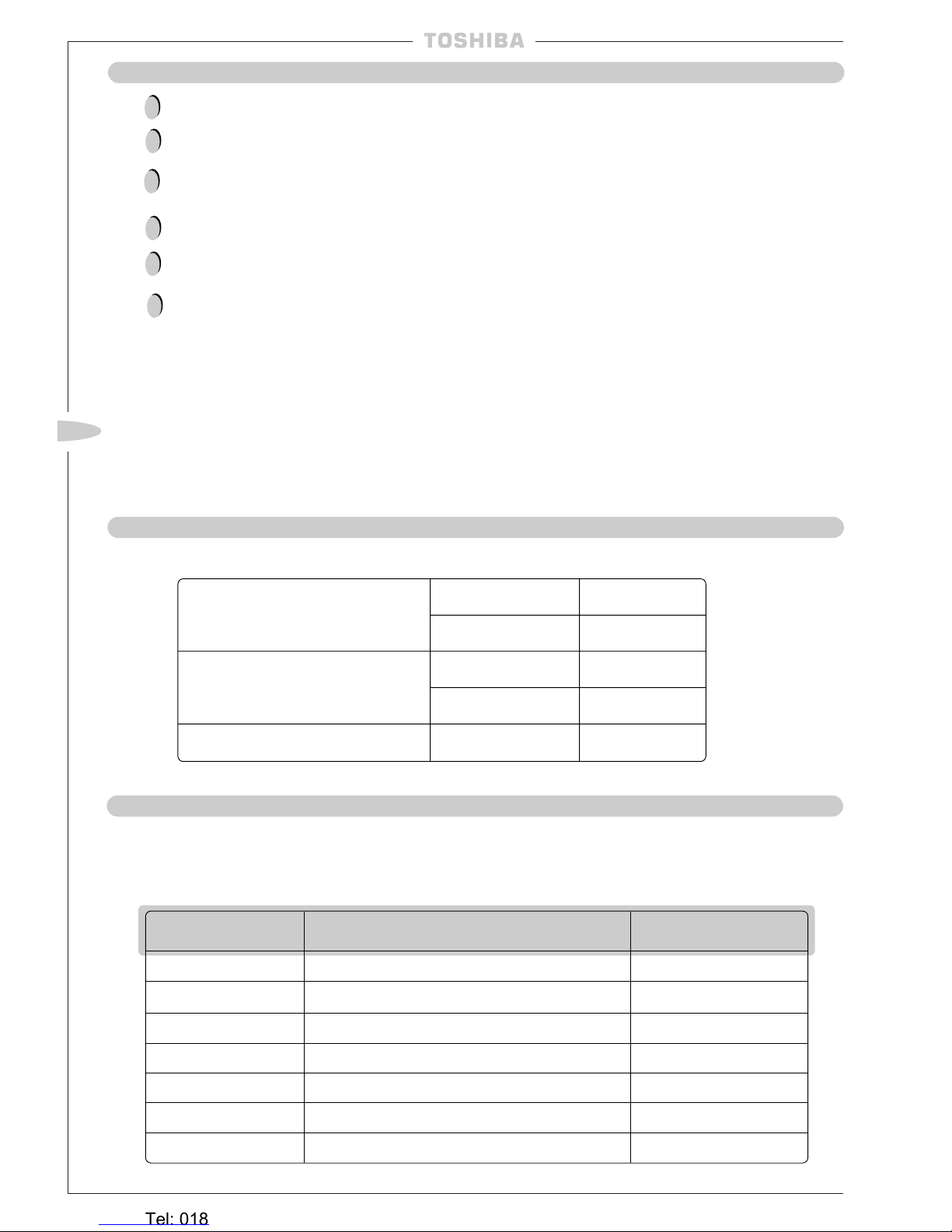
OPERATING CONDITIONS
KEY TO MODEL NAMES
Throughout this booklet, various types of indoor units will be referred to by model codes.
Details are shown in the table below:
UNIT DESCRIPTION HEAT PUMP CODE COOLING ONLY CODE
BUILT-IN DUCT TYPE BH, SBH B
CEILING TYPE CH (WIRED REMOCON), CHR (INFRARED REMOCON)C
WALL MOUNTED TYPE KH (WIRED REMOCON), KHR (INFRARED REMOCON)K
FLOOR CARCASE TYPE NH —
PAINTED FLOOR TYPE SH (WIRED REMOCON), SHR (INFRARED REMOCON)—
2-WAY CASSETTE TYPE TUH, TUH-1 TU, TU-1
4-WAY CASSETTE TYPE UH U
!
!
!
!
!
!
OUTDOOR TEMPERATURE
–2 ~ 43˚CCOOLING
–10 ~ 21˚CHEATING
ROOM TEMPERATURE
18 ~ 32˚CCOOLING
15 ~ 29˚CHEATING
ROOM HUMIDITY <80% COOLING
Heronhill - for all your Toshiba requirements
Tel: 01823 665660
www.heronhill.co.uk
Fax: 01823 665807
~ 3 ~
GB
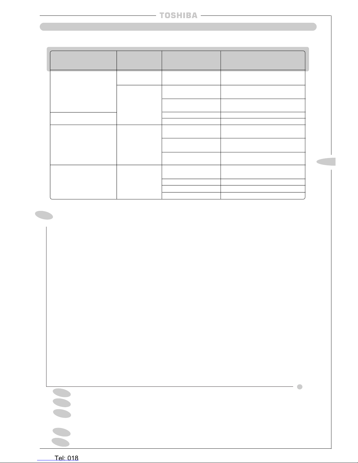
OPTIONAL ACCESSORIES
The following
optional
accessories are available:
CONTENTS...
Installation Instructions, Operating Conditions & Key to Model Names 2
Accessories 3 – 4
Outdoor Unit Location, Precautions, Service Space, Mounting 5 – 7
Indoor Unit Location, Precautions, Service and Installation Space 8 – 10
Unit Installation
BH/B units
11 – 12
Unit Installation
CH/CHR/C units
13 – 14
Unit Installation
KH/KHR/K units
15
Unit Installation
NH units
16
Unit Installation
SBH units
17
Unit Installation
SH/SHR units
18 – 19
Unit Installation
TU/TUH, TU-1/TUH-1 units
20
Unit Installation
UH/U units
21 – 22
Fresh Air Inlet, Details of Cut Out Hole 23
Air Outlet Duct, Details of Cut Out Hole 24
Drain Piping, Precautions, Piping Material and Heat Insulator, 25
Fixing the Drain Pan, Drain Hose Attachment 25
Drainage Check, Trial Run, Wired Remote Controller, Infra-Red 26
Refrigerant Piping, Precautions, Material and Sizes, 27
Permissible Piping Length and Head, Pipework Installation, System Purging 27
Additional Refrigerant, Heat Insulation, Pressure Measurement 28
Electrical Wiring, Precautions, Power Supply Specs and Wiring 29
Wiring Between Units, Connecting the Remote Controller and Group Control 30
Remote Controller, Installation of Remote Controllers, Heat Pump AI Models 31
and Cooling Only Models, Installation of AI Room Remote Controllers, Precautions, 31 – 32
Heat Pump models AI Room Remote Controller, Flush Wall Mounting, Wall Surface Mounting 31 – 32
Location of Infra-Red Remote Controller, Installing the Infra-Red Remote, 33
Infra-Red Remote Controller Mounting 33
Improving System Efficiency, Air Flow Adjustment, Increasing Heating Effect 33
Heat Pump Twin Set-up 34 – 35
Cooling Only Twin Kit Set-up 36 – 38
Final Installation Checks, Environmental Issues
39
E
I
NL
D
F
GB
Passer à la page 41 pour lire le manuel d’installation en français.
Die deutsche Montageanleitung finden Sie auf Seite 79.
Por favor, vaya a la página 117 para seguir las instrucciones del manual de
instalacíon en lengua española.
Il manuale d’installazione italiano è a pagina 155.
Zie bladzijde 193 voor de Nederlandse Installatichandleiding.
A
CCESSORY
M
ODELTYPE
A
CCESSORY
N
O
B
ASEMODEL
N
O
2-WAYC
ASSETTE
RBC-U133PG(W)-PE RAV-104, 134, 164TUH/TUH-1-PE
RBC-U134PG(W)-E RAV-134, 164TU/TU-1-PE
C
EILINGPANEL
RBC-U264PG(W)-E RAV-164, 264UH-PE
RAV-164, 264U-PE
4-WAYC
ASSETTE
RBC-U464PG(W)-E RAV-364, 464UH-PE
RAV-364, 464U-PE
I
NFRAREDCEILINGPANEL
RBC-U264PGR(W)-E RAV-164, 264UH-PE
RBC-U464PGR(W)-E RAV-364, 464UH-PE
RBC-RK162BE-PE RAV-164BH-PE
RAV-164B-PE
F
ILTERKIT
B
UILT INDUCT
RBC-RK262BE-PE RA V-264BH-PE
RA V-264B-PE
RBC-RK462BE-PE RAV-364, 464BH-PE
RAV-364, 464B-PE
43A01001 RAV-134CH, 134CHR, 134C-PE
RAV-164CH, 164CHR, 164C-PE
P
AINTEDBACKPANELKIT
C
EILINGSUSPENDED
43A01002 RAV-264CH, 264CHR, 264C-PE
(10 pack)
43A01003 RAV-364CH, 364CHR, 364C-PE
43A01004 RAV-464CH, 464CHR, 464C-PE
Heronhill - for all your Toshiba requirements
Tel: 01823 665660
www.heronhill.co.uk
Fax: 01823 665807
~ 4 ~
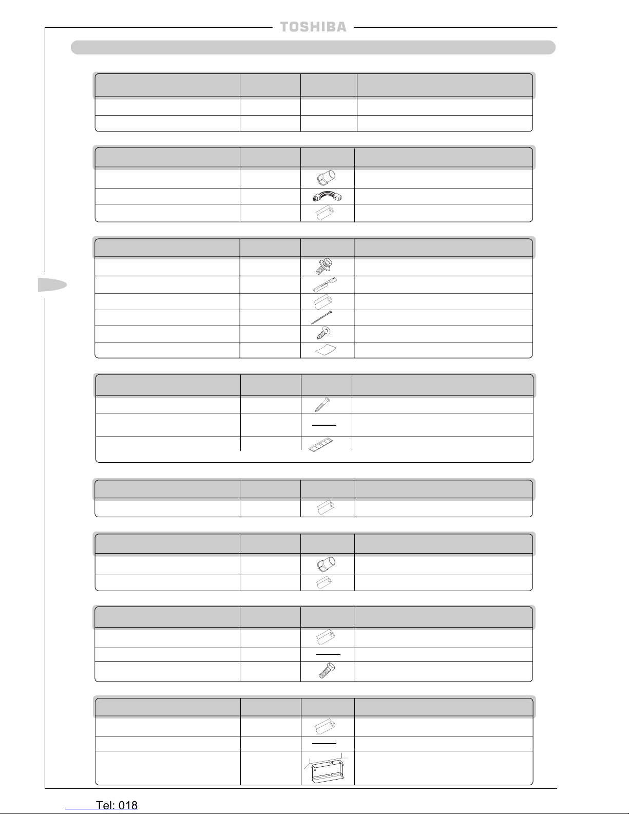
ACCESSORIES
DESCRIPTION QUANTITY DIAGRAM APPLICATION
Owner’s Manual 1 — For use by customers
Installation instructions 1 This book —
COMMON
BH, B Units
TUH, TU, TUH-1, TU-1 Units
DESCRIPTION QUANTITY DIAGRAM APPLICATION
PVC Socket 1 For drainpipe connection
Connector assembly 1 For fan motor tap changing
Pipe insulation 2 For insulating the pipe connections
DESCRIPTION QUANTITY DIAGRAM APPLICATION
Screws – 5.1mm dia x 45mm long
8 For fixing the installation bracket
Template for installation of 1 For ease of marking the
indoor unit location of installation bracket
Installation bracket* 1 For mounting the indoor unit on the wall
*This part is temporarily attached to the back of the indoor unit
NH Units
DESCRIPTION QUANTITY DIAGRAM APPLICATION
Pipe insulation 2 For insulating the pipe connections
DESCRIPTION QUANTITY DIAGRAM APPLICATION
Pipe insulation 2 For insulating the pipe connections
Cardboard template 1
For installation of the cassette and ceiling panel
Bolt (M5 x 20mm) 4 To secure the panel to the cassette
UH, U Units
DESCRIPTION QUANTITY DIAGRAM APPLICATION
Pipe insulation 2 For insulating the pipe connections
Cardboard template 1
For installation of the cassette and ceiling panel
Insulation block
4 (164/264)
For 2-directional and
2 (364/464)
3-directional air outlet
CH, CHR, SH, SHR, C Units
KH, KHR, K Units
DESCRIPTION QUANTITY DIAGRAM APPLICATION
Hexagon bolt 4 For securing the hangers
Drain piping fixing plate 1 For fixing rear side drain piping
Pipe insulation 2 For insulating the pipe connections
Nylon band 10
For fixing drain piping and pipe insulation
Tapping Screw 2
For fixing the side panels after installing the unit
Insulator 1 For insulating the knock-out position
SBH Units
DESCRIPTION QUANTITY DIAGRAM APPLICATION
PVC Socket 1 For drainpipe connection
Pipe insulation 2 For insulating the pipe connections
Heronhill - for all your Toshiba requirements
Tel: 01823 665660
www.heronhill.co.uk
Fax: 01823 665807
~ 5 ~
GB
OUTDOOR UNIT LOCATION
Avoid installing the outdoor unit in the following locations:
Where there is danger of flammable gas leakages.
Where there are high concentrations of oil.
Where the atmosphere contains an excess of salt (as in coastal areas).
The air conditioner is prone to failure when used under this condition unless special maintenance
is provided.
Where the airflow from the outdoor unit may cause annoyance.
Where the operating noise of the outdoor unit may cause annoyance.
Where the foundation is not strong enough to fully withstand the weight of the outdoor unit.
Where the water drainage may cause a nuisance or a hazard when frozen.
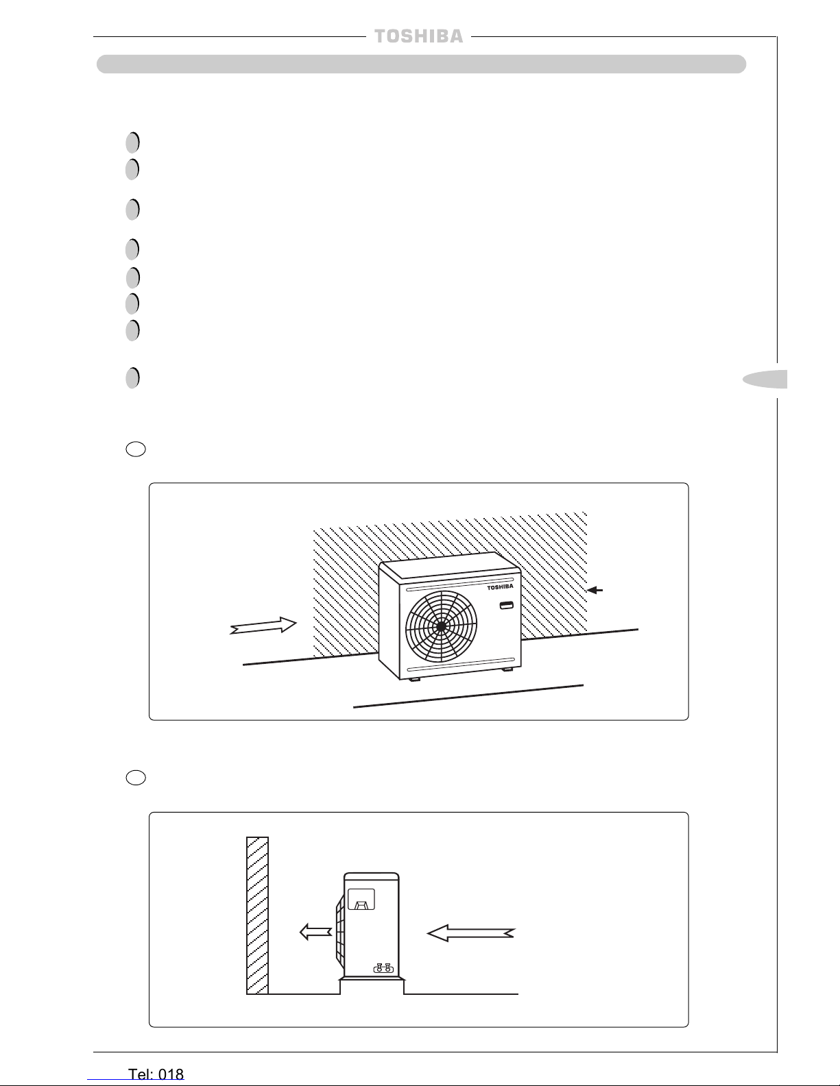
Where strong winds may blow against the air outlet of the outdoor unit.
(The high pressure switch could be tripped if a strong wind should blow against the air outlet
during cooling operation). Where this condition is likely to be present, protect the outdoor unit
against winds, for example by:
Precautions
2
Installing the outdoor unit with the air outlet facing the wall, such as on an exposed rooftop:
Strong
Strong wind
Rooftop
Airflow
Wall
1
Installing the outdoor unit in parallel with the building so that it can be protected by other buildings:
!
!
!
!
!
!
!
!
Building
Heronhill - for all your Toshiba requirements
Tel: 01823 665660
www.heronhill.co.uk
Fax: 01823 665807
~ 6 ~
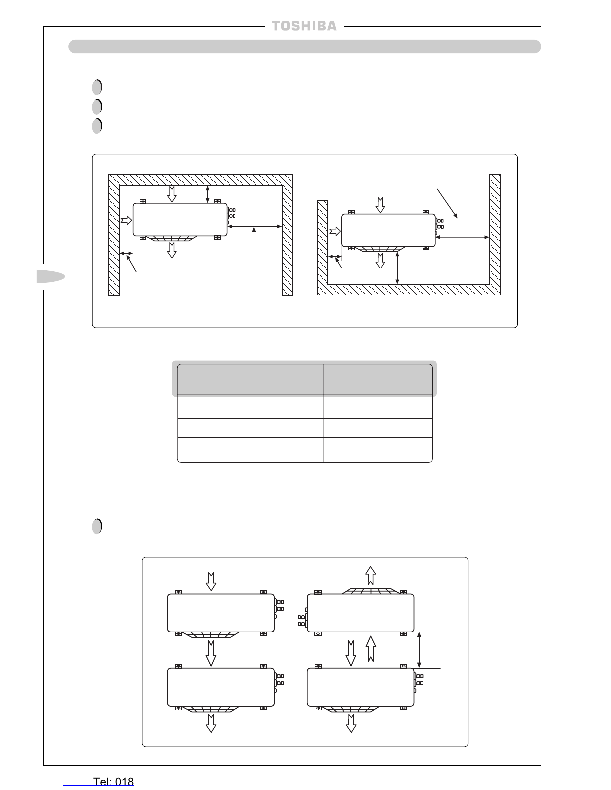
OUTDOOR UNIT LOCATION
Ensure that there is sufficient space around the outdoor unit for operation, installation and servicing;
Any obstructions of the airflow must be at least 300mm from the front of the unit;
All dimensions are minimum.
Service Space
150mm or
more
Air inlet facing the wall
(Wiring and piping space)
500mm or more
300mm or more
Air outlet facing the wall
Do not allow units to be situated so that outlet air from one unit is discharged directly into the intake
of another unit as indicated below:
Mounting
Airflow Path
Model A(mm)
RAV-364AH8/A8 150
RAV-464AH8/A8 150
Remaining models 100
!
!
!
!
A: mm or more
(see table below)
(Wiring and
piping space)
500mm or more
3
7
300mm
min
A: mm or more
(see table below)
Heronhill - for all your Toshiba requirements
Tel: 01823 665660
www.heronhill.co.uk
Fax: 01823 665807
~ 7 ~
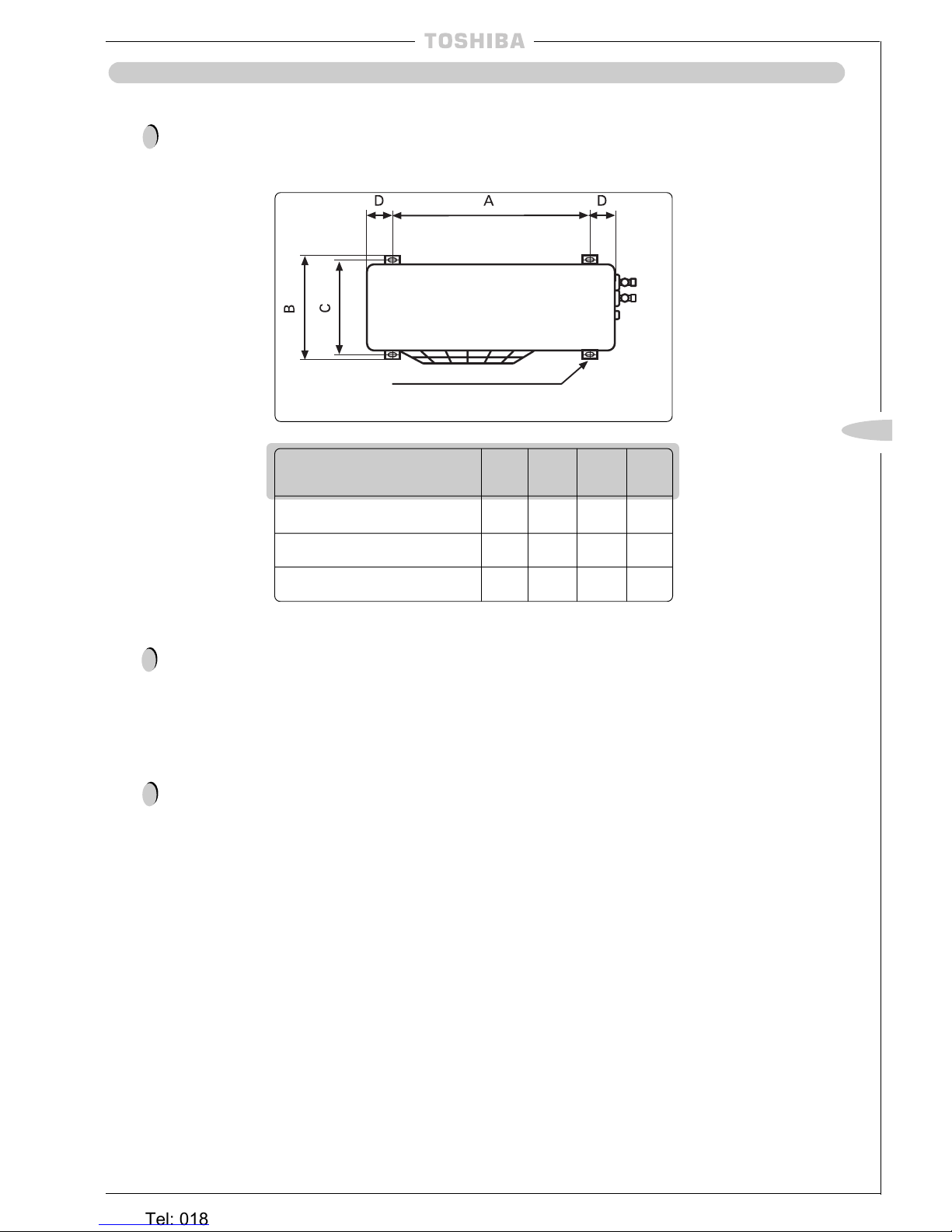
OUTDOOR UNIT LOCATION
Secure the outdoor unit to a sturdy and flat foundation using four anchor bolts.
The anchor bolt pitch is shown in the diagram below:
Mounting
continued
4 x (12mm x 18mm) Slots
Model A B C D
RAV-364AH8/A8 840 440 416 45
RAV-464AH8/A8 840 440 416 45
Remaining models 790 364 340 45
In areas subject to heavy snowfalls, protect the outdoor unit from snow as follows:
(i) Install the unit on a stand which will keep the unit above the level of the standing snow.
(ii) The stand must facilitate water drainage.
(iii) Install snow protection hoods over the air intake and outlet. Ensure that the airflow is not
affected.
Failure to take adequate measures in this respect may result in the unit malfunctioning.
!
!
(MM) (MM)
(MM) (MM)
!
GB
Heronhill - for all your Toshiba requirements
Tel: 01823 665660
www.heronhill.co.uk
Fax: 01823 665807
~ 8 ~
~ 8 ~
INDOOR UNIT LOCATION
Avoid installing the indoor unit in the following locations:
Where there is danger of flammable gas leakages.
Where there are high concentrations of oil.
Where the atmosphere contains an excess of salt (as in coastal areas).
The air conditioner is prone to failure when used under this condition unless special maintenance
is provided.
Where high concentrations of organic solvent are present.
Where a machine that generates high frequencies is operated.
Where the unit will not be horizontal.
Where the ceiling height is more than 3m.
Where the floor/wall/ceiling structure is unable to support the weight of the unit.
Where it is not possible to fix the unit hangers,
e.g.
window glass.
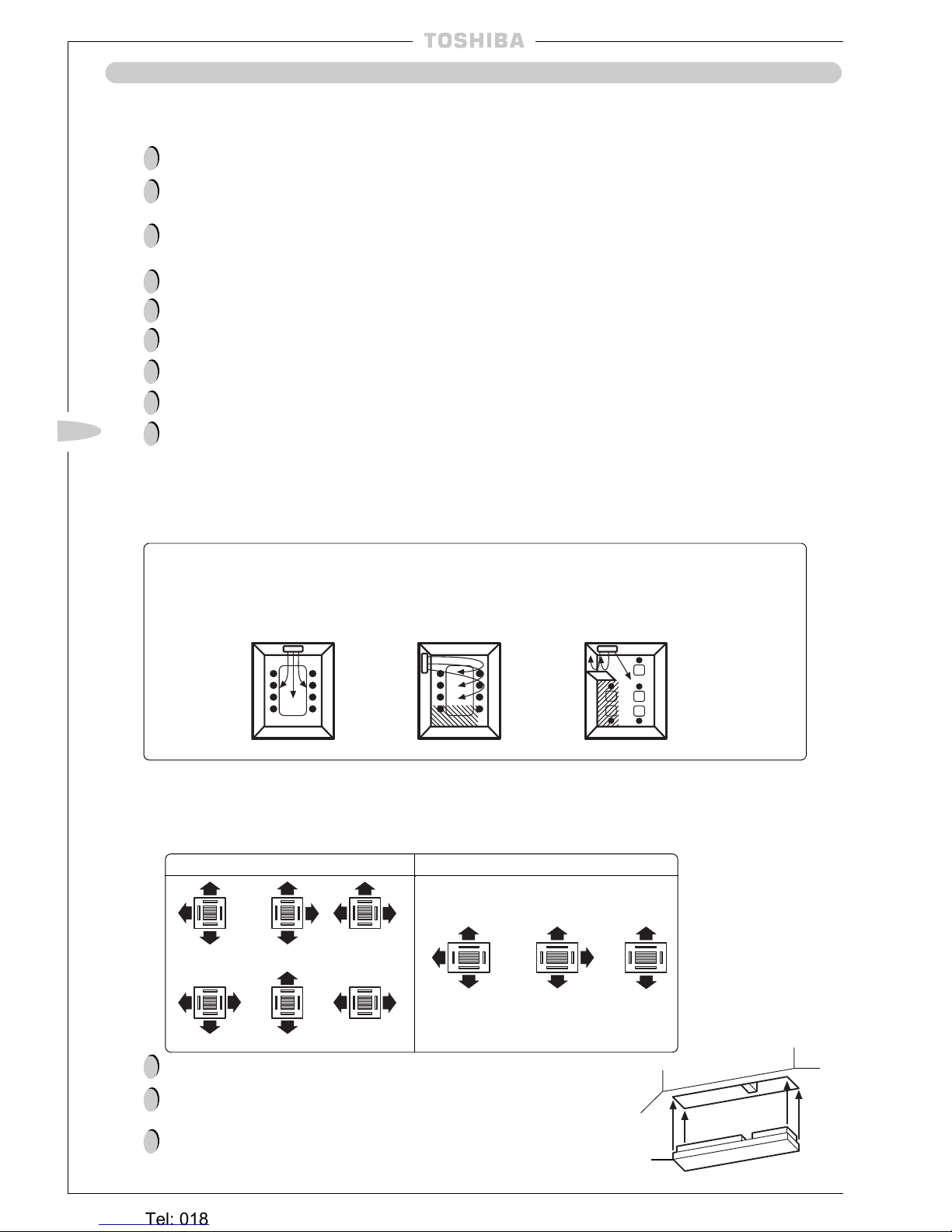
Locate the unit so as to provide uniform circulation of chilled air.
Location Precautions
Good location —
Evenly cooled
Bad location —
Oblique-line
area not well
cooled \\\\\
Bad location —
Oblique-line
area not well
cooled /////
7
7
3
If a good location is not possible, use a fan to circulate the air evenly throughout the room.
— UH/U Units only —
Choose the number of airflows that are required, depending on the shape of the room and the location of the indoor unit.
Insulation
Block
RAV-164/264UH/U RAV-364/464UH/U
!
!
!
!
!
!
!
!
!
!
!
!
— CH/CHR/C and KH/KHR/K Units only —
Avoid locating the unit as shown in the 7-marked figures below:
It is not possible to block the air flow from the longer sides of the unit.
The number of airflow directions cannot be adjusted after installation.
Insert insulation blocks, which are supplied as accessories,
at each side where the airflow is not required,
as shown in the diagram opposite.
3-way 3-way 3-way
3-way 3-way 2-way
3-way 2-way 2-way
Heronhill - for all your Toshiba requirements
Tel: 01823 665660
www.heronhill.co.uk
Fax: 01823 665807
~ 9 ~
GB
~ 9 ~
INDOOR UNIT LOCATION
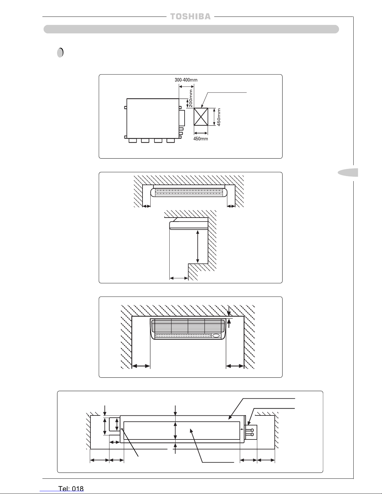
ALWAYS ENSURE THAT THERE IS SUFFICIENT SPACE AROUND THE INDOOR UNITS FOR
INST ALLATION AND SERVICING:
Service and Installation Space
BH/B Units
CH/CHR/C Units
KH/KHR/K Units
300mm or more
30mm or more
300mm or more
500mm or
more
400mm
or
more
150mm
or more
!
Provide an inspection
hole in this position
Inspection hole
150mm
or more
NH Units
Minimum
Upper Plate/Duct Plate
Minimum
60mm
25mm
20mm
140mm
65mm
90mm
150mm
100mm
Drain Catch
Fixing location to
floor/base
160mm
145mm
Air Outlet
150mm
Heronhill - for all your Toshiba requirements
Tel: 01823 665660
www.heronhill.co.uk
Fax: 01823 665807
~ 10 ~
~ 10 ~
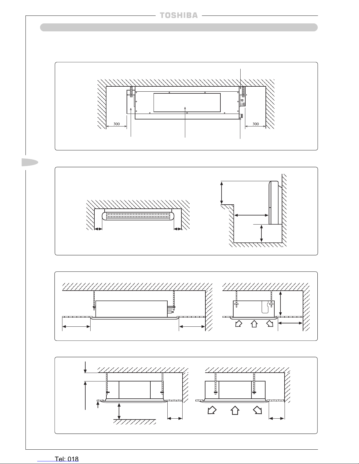
INDOOR UNIT LOCATION
Service and Installation Space
continued
SBH Units
SH/SHR Units
TUH, TUH-1/TU, TU-1-PE Units
UH/U Units
Plan View
150mm
or more
150mm
or more
400mm
or more
500mm
or more
150mm
or more
600mm 600mm
600mm
200mm
15mm or more
1000mm
or more
Obstacle
1000mm
or more
Ceiling
1000mm or more
Terminal box (wiring connections)
Drain pipe connections
Air Outlet
Electrical box
(PCB, transformer, MF capacitor)
Heronhill - for all your Toshiba requirements
Tel: 01823 665660
www.heronhill.co.uk
Fax: 01823 665807
~ 11 ~
GB
~ 11 ~
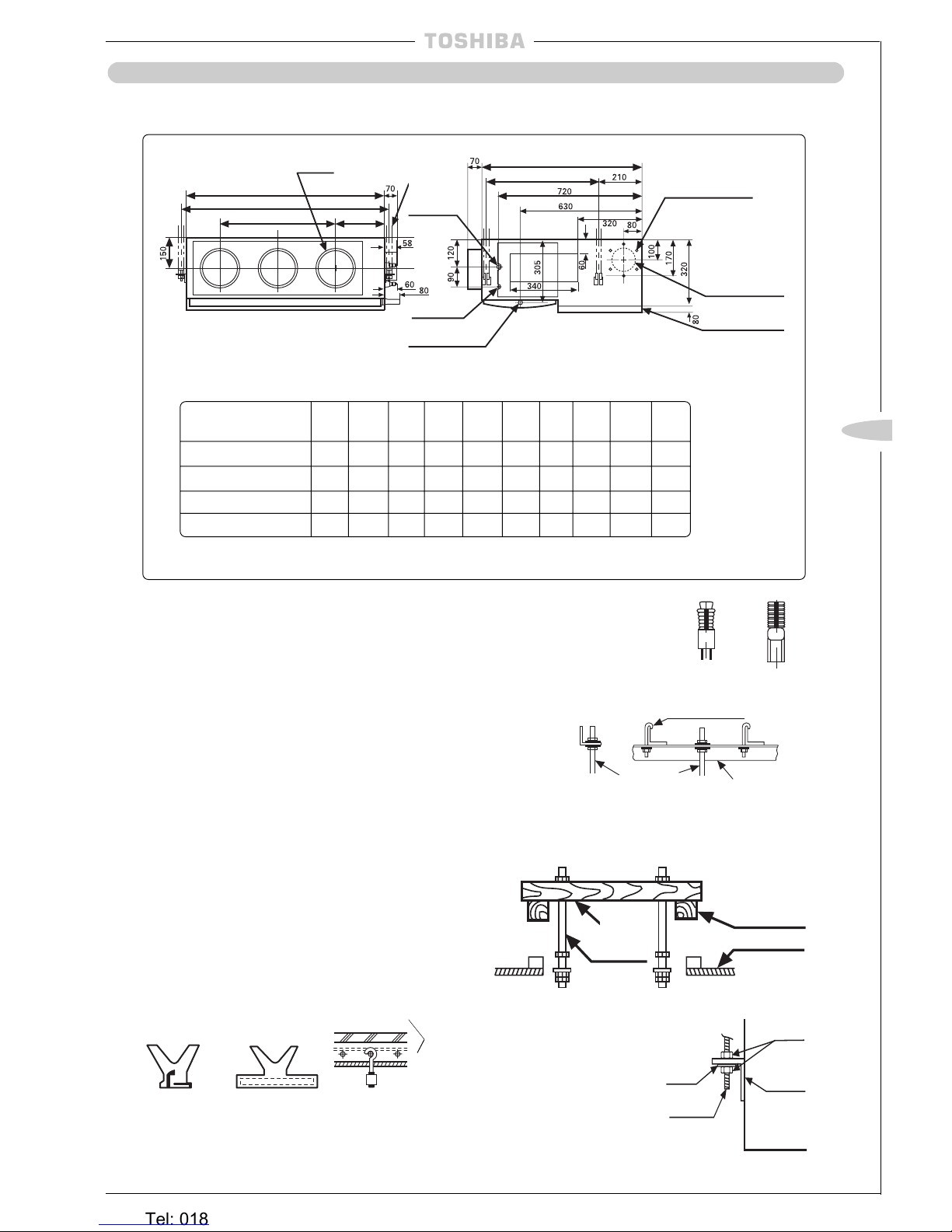
INDOOR UNIT LOCATION
l
Check the dimensions of the unit illustrated in the following figure:
Unit Installation –
BH/B Units
Installing Ø 10 Hanging Bolts (4 pieces)
l
Install the hanging bolts at the intervals shown in the
following figure.
l
Use Ø 10 hanging bolts (to be locally procured).
Ceiling preparation:
The actual procedure differs according
to the structure. Consult your builder or whoever was
responsible for the interior of the house/building.
Removal of part of the ceiling plate:
(1) In order to ensure that the ceiling is kept perfectly
horizontal and to prevent the ceiling from vibrating, the
ceiling framework must be reinforced.
(2) Cut and remove part of the ceiling framework.
(3) Reinforce the ends of the ceiling framework where it was
cut and add framework to secure the ends.
l
Some piping and wiring connections must be made in the
ceiling after the unit has been suspended. After selecting where
the unit will be installed, decide on the direction of the piping
connection. If the ceiling is already installed, prepare the
refrigerant pipes, drain pipe, indoor to outdoor unit connection
wiring and the remote control cord at the piping and wiring
connection positions before suspending the indoor unit.
Hanger
bolt
Hanging bolt
Hanging
bolt
Beam
Ceiling
Model (RAV-) A B E Ø F Ø G H J K M N
264BH 1000 1050 1080 15.9 9.5 252 580 290 2 3
364BH/B, 464BH/B 1350 1400 1430 19.0 9.5 252 930 310 3 4
164BH/B 700 750 780 12.7 6.4 252 280 280 1 2
264B 1000 1050 1080 15.9 9.5 252 580 290 2 3
Sliding bracket
Reinforcing
bar
Foundation bolt
(Foundation bolt for
hanging the piping)
Angular bracket
for support
Installation on a wooden structure:
Place a length of wood of the appropriate size across two
beams and install the hanging bolts onto this length of wood.
Installation on a steel frame:
Use the angular
bracket in
the structure
or install
one for support.
Installation on an existing concrete slab:
Use hole-in anchors, hole-in plugs
or hole-in bolts for the installation.
Hanging Unit
(1) Raise the unit by using a lift-
ing device, then secure the
hangers to the hanging
bolts. Be sure to fix the nuts
onto both the upper and
under side of the hanger
and the washer (under side
only);
(2) Install the unit horizontally
by using a level. Failure to
do this will cause water
leakages.
Nut
Hanger
Hanging
Bolt
Washer
How to Install the Hanging Bolts
Installation on a newly installed concrete slab:
Use insert brackets or foundation bolts for the installation.
Cross
length of
wood
Knife shaped
bracket
(Gas ø F)
Hanging Bolt Pitch B
Refrigerant Pipe
Connection
Unit Dimension A
Hanging Bolt
4-M10
Provided at site
Nx Ø200
Air Outlet
Drain pipe connection
(inner diameter 32)
(diameter 32 minimal for PVC pipes)
Refrigerant pipe
connection
(liquid ø G)
Hanging Bolt Pitch:565
Unit Dimension:800
J = M x K
(H)
6 x Ø4 holes (Ø160)
Fresh air inlet Ø125
cut-out (other side)
Filter kit
Heronhill - for all your Toshiba requirements
Tel: 01823 665660
www.heronhill.co.uk
Fax: 01823 665807
~ 12 ~
~ 12 ~
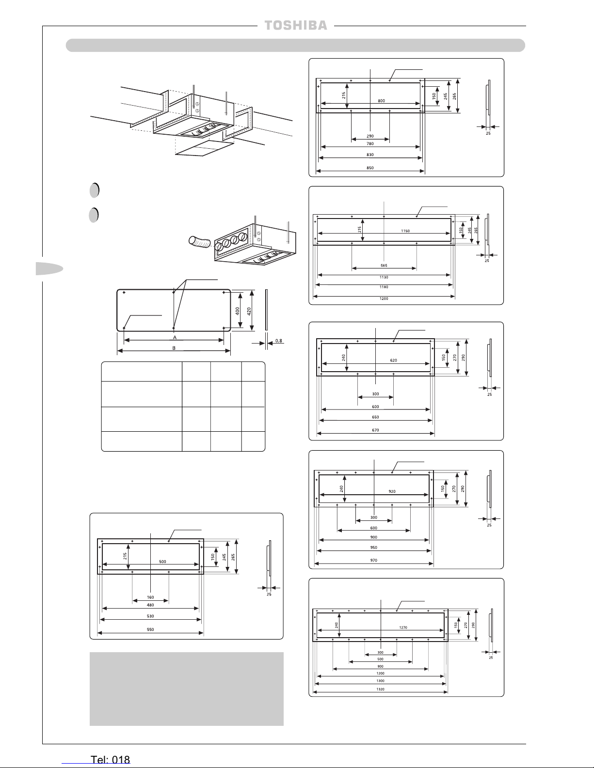
INDOOR UNIT LOCATION
Unit Installation –
BH/B Units continued
Connection of Ducting
Remove the duct connection assembly (attachment)
before connecting the supply duct.
!
Flexible duct
The maximum length of
flexible ducting is 10m.
l
To connect the shelter
board under the lower air
inlet of unit, prepare the
shelter board locally, as
shown below.
!
Model (RAV-) A B C
264BH/B 700 1000 2
364BH/B, 464BH/B 1050 1350 2
164BH/B 400 700 —
Optional Accessory
l
A TOSHIBALong-Life Filter Kit is available as an
optional accessory.
l
The Filter Kit can be installed on either the lower or
rear air inlet of the Duct Type unit.
l
To connect square duct, prepare the connection flange
locally as shown below:
RAV-164BH/B
Supply Flanges
RAV-264BH/B
RAV-364BH/B, RAV-464BH/B
Return Flanges
RAV-164BH/B
RAV-264BH/B
RAV-364BH/B, RAV-464BH/B
Shelter Board C x Ø6 holes
Supply duct
(local procurement)
12 – ø 6 holes
14 – ø 6 holes
14 – ø 6 holes
14 – ø 6 holes
18 – ø 6 holes
22 – ø 6 holes
4 x Ø6 holes
Return duct (local
procurement)
Shelter board
(local procurement)
Heronhill - for all your Toshiba requirements
Tel: 01823 665660
www.heronhill.co.uk
Fax: 01823 665807
~ 13 ~
GB
~ 13 ~
INDOOR UNIT LOCATION
Unit Installation –
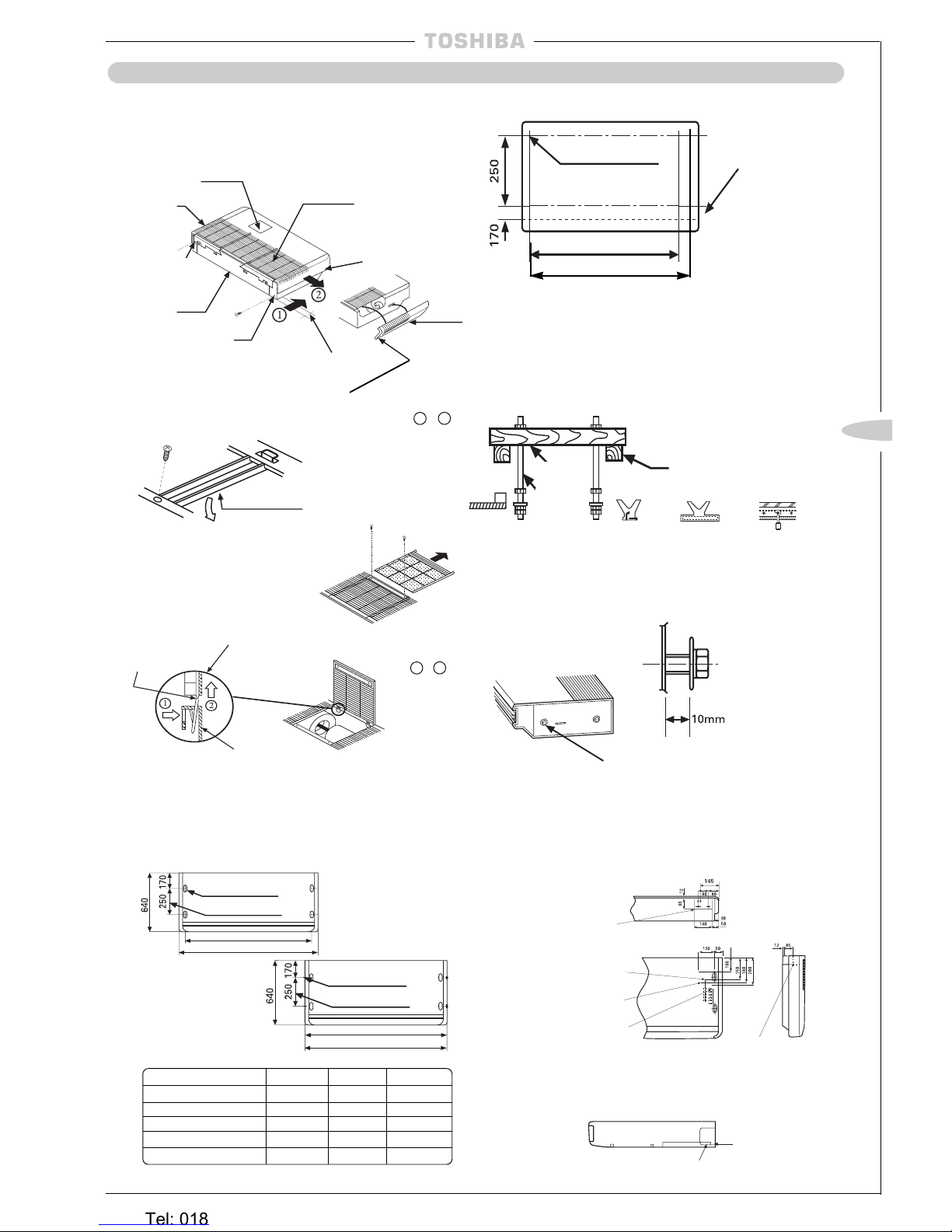
CH/CHR/C Units
Before Installation
1 Take off the accessories.
2 Remove
the hanger
(left, right).
4 Remove the side panels by hand.
Slide them in order of 1 - 2 .
5 Pull the air filter
out then remove
the inlet grille fixing
screws.
Side
panel
(left)
Body
Inlet grille
10-20mm
l Securely fix left
and right side panels
with a screw
supplied after unit
installation.
Installing Ø 10 Hanging Bolts
Ø Hanging Bolts are procured locally
l
Install hanging bolts at the spacings shown below.
Shipping fixture
(centre)
Detail figure of the hinge
portion
INNER HANGING
OUTER HANGING
Hole for hanging bolt
Bmm (Hanging bolt pitch)
Amm
Model (RAV-) Amm Bmm Cmm
134CH/CHR/C 1030 920 1020
164CH/CHR/C 1030 920 1020
264CH/CHR/C 1230 1120 1220
364CH/CHR/C 1430 1320 1420
464CH/CHR/C 1630 1520 1620
The positions of the hanging bolts are printed on the carton
box. (The size is not printed.)
Position of hanging bolt
(ø10 printed)
Bmm (inner hanging)
Cmm (outer hanging)
Installing method of the Hanging Bolt
Newly-built concrete slab
Install hanging bolts with
inserts, embedded bolts, etc.
Wooden-strutted room
Install hanging bolts on a square
wooden piece placed over beams.
Edge
(sharp
insert)
(Slide
insert)
Embedded bolt
of piping
Reinforcing bar
Installing Hexagon Bolt
(accessory)
Allow a spacing of
about 10mm
M8 x 25mm hexagon bolts (4)
Determining installation position and direction
of the piping and wiring
BACK VIEW
Knock out
(rear attachment)
Gas line connection
Knock out
(right or left attach-
ment)
Liquid line connection
TOP VIEW
Opening Knock Out Hole
Cut the slit
portion by a
saw or knife
In case of
right or left
attachment
Slit
3 Remove all the
metal shipping fixtures (left corner,
centre, right corner).
Side panel
(right)
Wooden
piece
Hanging
bolt
Drain connection
(OD 20mm)
Beam
Hole for hanging bolt
Cmm (Hanging bolt pitch)
Amm
(4 – 12 x 27 slots)
Hanging bolt pitch
(4 – 12 x 27 slots)
Hanging bolt pitch
l The dotted
line indicates
the rear end
of the unit. To
be detached
on the dotted
line.
Embedded
bolt
SIDE VIEW
To remove the
inlet grille take the
hinge portion off in
order of 1 - 2 .
Hinge
Body
Heronhill - for all your Toshiba requirements
Tel: 01823 665660
www.heronhill.co.uk
Fax: 01823 665807
~ 14 ~
~ 14 ~
INDOOR UNIT LOCATION
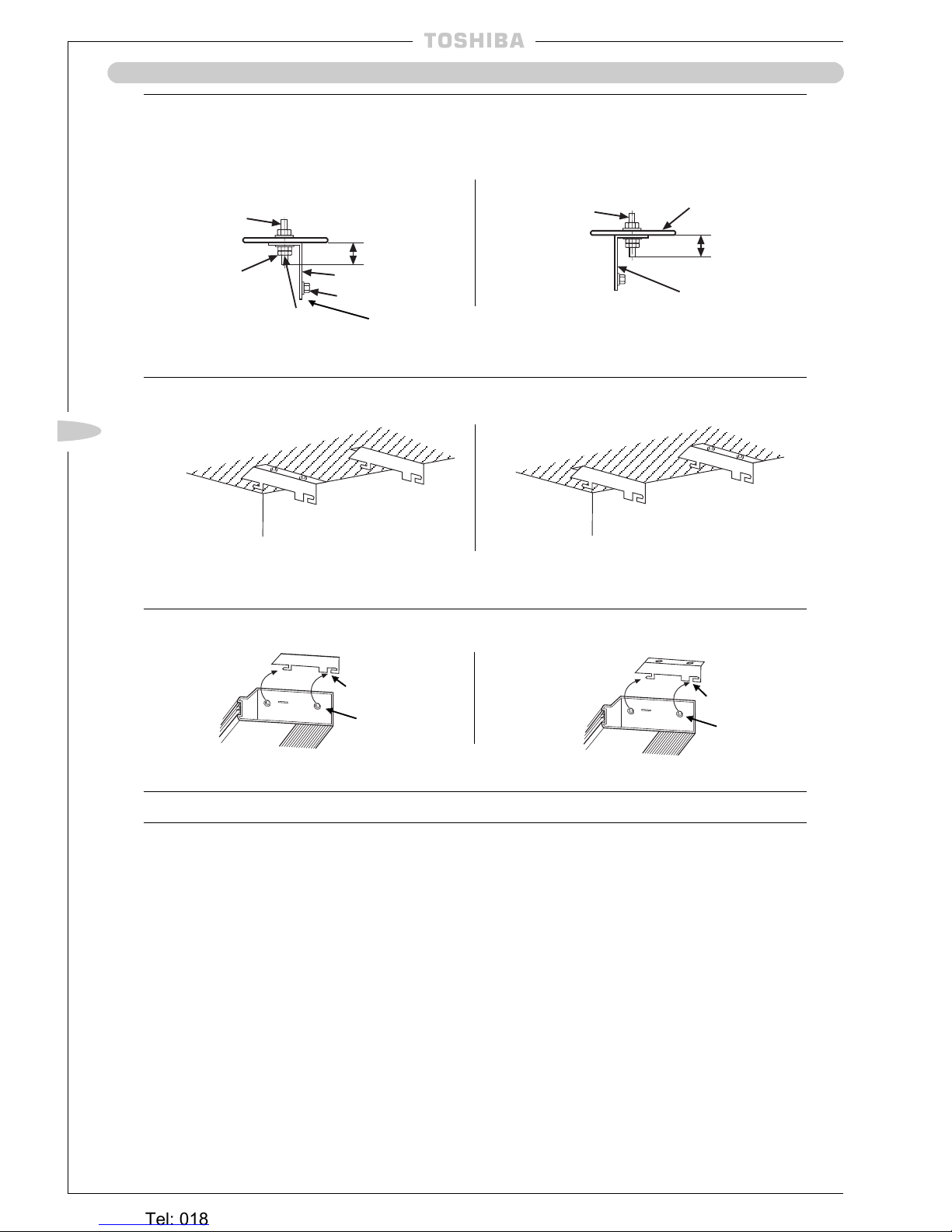
Hanging the Indoor Unit
(1) Fitting Hanger
INNER HANGING
OUTER HANGING
Hanging bolt
Ceiling board
Bolt cover
40mm or less*
Hanger
Hexagon bolt
Side panel (right)
M10 Plate
washer
Double nut
Hanging bolt
Body
(2) Fitting State of Hanger
Ceiling
Ceiling
Wall
Wall
In case of inner hanging, adjusting height of indoor unit is
impossible after hanging – adjust it at this state
(3) Hanging the Indoor Unit
Fit the Hexagon bolts of the unit into slit grooves
(4) Fasten the Hexagon bolts to hang the unit
Remote Control Cord, CH/C Models only
l
Wire the cord over the refrigerant piping and the drain piping.
l
If the cord was wired under the piping, it would cause difficulty in pulling out the air filter.
Ceiling board
40mm or less*
Hanger
*Allow a jutting out length of 40mm or less
Slit grooves
Hexagon bolt
Hexagon bolt
Slit grooves
Heronhill - for all your Toshiba requirements
Tel: 01823 665660
www.heronhill.co.uk
Fax: 01823 665807
~ 15 ~
GB
~ 15 ~
INDOOR UNIT LOCATION
Unit Installation –
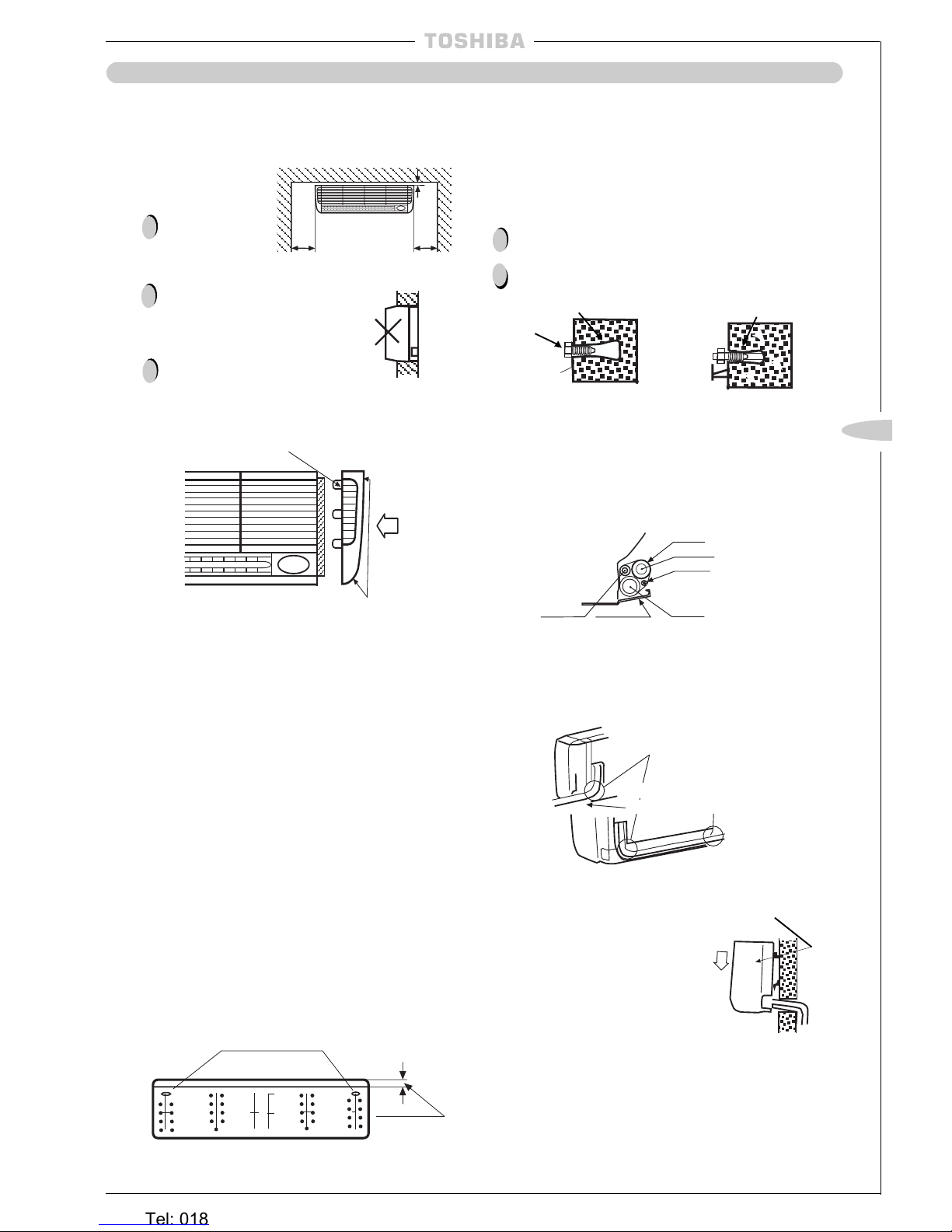
KH/KHR/K Units
l
When mounting the indoor unit on the wall, follow the
instructions below:
Precautions
To drain well make
sure the unit is
mounted horizontally
or tilted slightly to the
right as seen from
the front.
Do not embed the
unit in the wall.
When installing the
side panel, remove
the air filter (on the
right or left) and
make sure the lugs
are in the lug holes.
Then, push the side
panel until it fits
securely to the unit.
l The indoor unit weighs up to 30kg including the bracket.
Before mounting the unit, make sure the wall is strong enough.
30mm or more
(Horizontal or
tilted slightly to
the right)
300mm
or more
300mm
or more
Indoor unit
Lugs
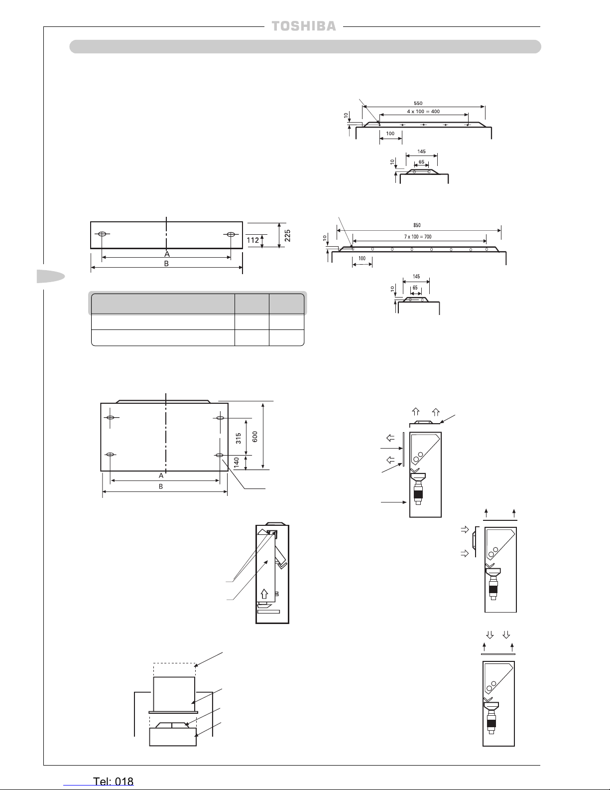
Installing Installation Bracket
l
Referring to the template, determine the location of the
indoor unit and cut the pipe hole as indicated.
l
When passing
the refrigerant pipe through a wall in which a
lath is used, be sure to utilize pipe insulation.
In the case of a wooden wall (large wall):
(1) According to the distance between the indoor unit and the
ceiling, determine the vertical position (height) of the
installation bracket;
(2) Adjust the lateral position of the installation bracket with-
out changing the height so that each screw hole in the
bracket comes in the centre of a pillar or stud;
(3) In the case of a wooden wall, the distance between the
pillars is usually 900mm or 1,800mm (2,700mm) and within this length, studs are located at intervals of 300 to
500mm. Be sure to install the bracket securely by driving
the accessory screws into the pillars and studs. At this
time, in order to prevent the indoor units from falling forward, be sure to firmly fix the unit by tightening the screws
in the holes at both ends of the bracket (those indicated
by oblique lines on the template);
(Holes indicated by oblique lines on the template)
Wider side
(4) Make pilot holes before fitting screws.
In the case of a reinforced concrete wall:
(1) In the selected areas on the reinforced concrete wall, bore
holes at intervals of 480mm, and fit anchors;
(2) Attach the installation bracket to the wall by screwing bolts
or nuts into the anchors.
However, in the case where the hole anchors are used,
the depth of the holes should be adjusted so that the nut
heads extend no more than 15mm.
Precautions
There may be a wire conduit embedded in the wall. Check the
blue prints with the builder;
Make sure that the installation bracket is fitted securely before
mounting the indoor unit.
!
!
!
!
!
Clip anchor
Bolt
Installation
bracket
Nut w/threaded
hole 8mm dia.
Less than 15mm
In the case of the pipe on the back:
l Using the template, position the pipe hole and bore the
hole slightly downward.
Binding of Pipes and Drain Hose
(1) In the case of the right-side pipe and the left-side pipe
bind the pipes and the drain hose as shown in the figure
below being careful that they do not protrude out of the
back of the indoor unit.
Tape
Gas pipe
Cable
Screw holding side
panel
Lower cabinet
Drain hose
(2) Make sure the drain hose does not sag.
(3) Apply proper insulation on both pipes, otherwise they
will sweat or cause a problem.
(4) Be cautious while bending the pipes to assure their
bending radius is 100mm or more.
Right-side pipe exit
While bending, bend the pipe holding the bending portion by hand
Left-side pipe exit
(5) Cut out the knockout portion for the pipe with a knife
and smooth the edge.
Installation
bracket
Installation of Indoor Unit
(1) Pass the pipe through the pipe hole in
the wall and mount the indoor unit on
the upper end of the installation
bracket.
(2) Move the indoor unit to the right and
left checking to see that the upper end
of the bracket is fitted in the unit.
(3) Make sure the lower end of the
pipe-holding bracket hooks the lower
cabinet to prevent the indoor unit from
moving upward.
Removal of Indoor Unit’s Right Side Panel
(1) Remove the air filter and then remove the side panel.
(2) Unfasten the right screw of the right end inlet grille.
(3) Remove the two screws holding the side panel.
(4) The side panel has lugs located on the front edge. Hold
the rear edge of the panel and pull forward to remove.
(5) To replace the removed side panel, locate lugs and push
firmly in place.
Installation of right side
panel
Liquid pipe
Side panel knockout
Concrete
wall
Hole in anchor
Concrete
wall
Hang
Heronhill - for all your Toshiba requirements
Tel: 01823 665660
www.heronhill.co.uk
Fax: 01823 665807
~ 16 ~
~ 16 ~
INDOOR UNIT LOCATION
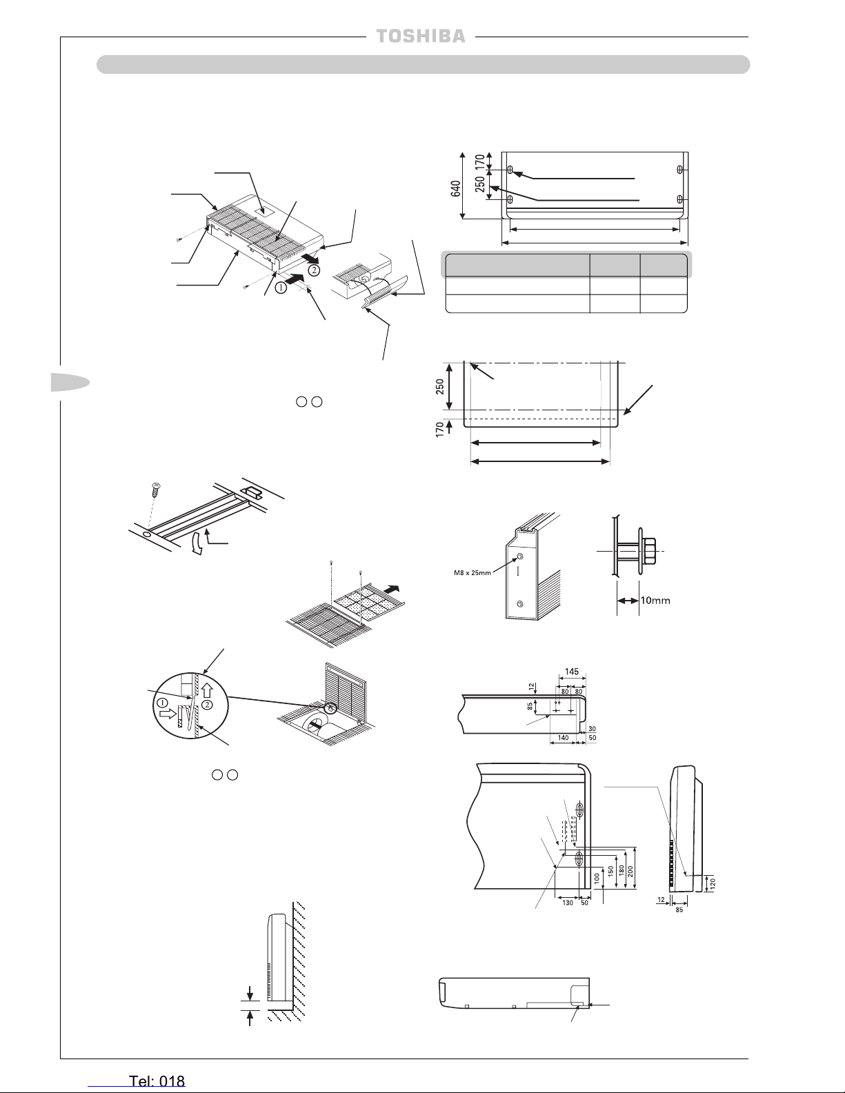
Unit Installation –
NH Units
(1) There are EPS cushions protecting the unit from
damage during transportation. They are located under
both side plates. Remove the EPS cushions before
installation. Also, remove the transportation tape from
the electrical box.
(2) Install the indoor unit before construction of the
architectural surround.
Fixing the Unit
l When fixing the indoor unit to the floor or wall, use ø8mm
anchor bolts using the fixing point on the unit.
Front surface
Fixing onto the Floor Over-view
Model A B
RAV-104NH-PE 586 610
RAV-134/164/264NH-PE 880 910
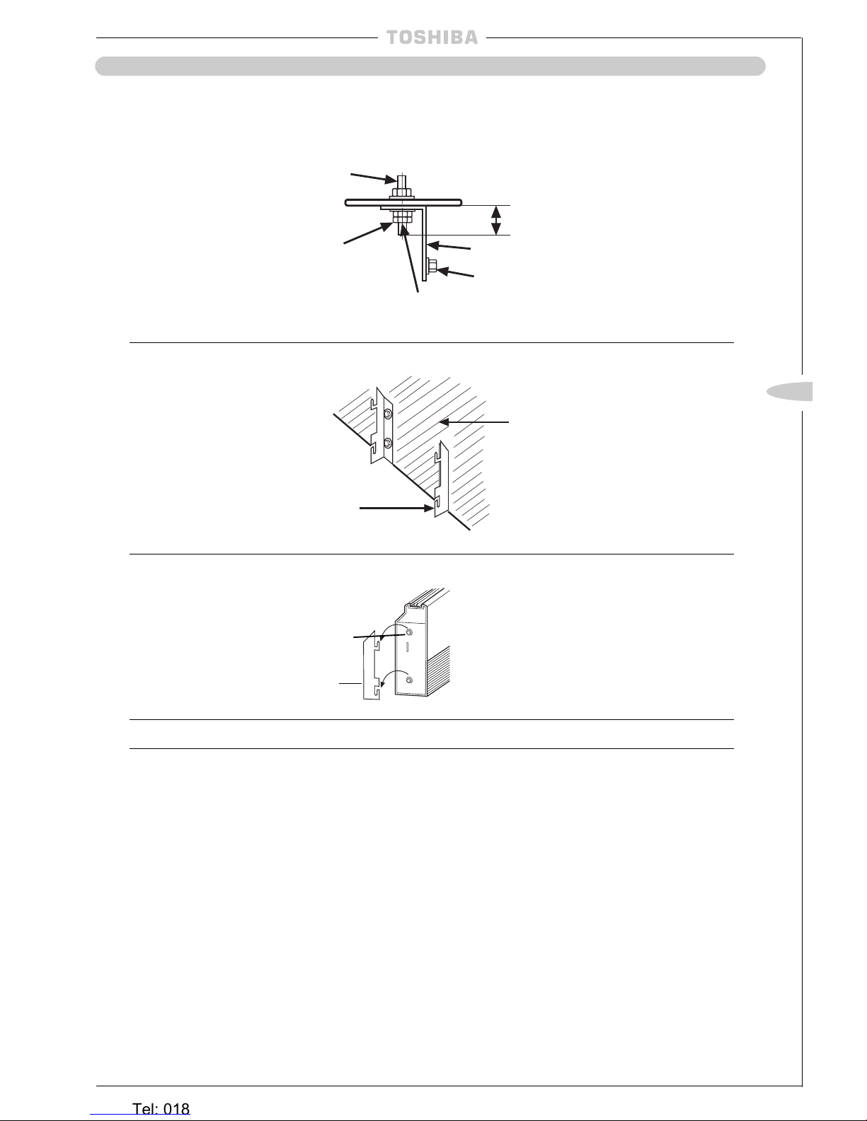
Fixing onto the Wall – Front View
l Note: If you are fixing the rear plate onto the wall please
remove the electrical box as shown.
Floor Holes on
rear plate
(1) Remove the two
screws from the
top of the electrical
bracket.
(2) Slide the box along
as indicated by the
arrow and remove
from the unit.
Electrical box
To connect the duct, prepare the connection flange
locally as shown:
RAV-104NH-PE
RAV-134/164/264NH-PE
Connection of Ducting
Architectural Surround
Air Outlet Grille
(local procurement)
Supply Duct
(local procurement)
Duct Joint Plate
Unit
Duct Outlet
The indoor unit has two choices of air outlet. The indoor
unit will already be positioned in the vertical air outlet
direction, if a side/horizontal air outlet direction is required
the following operations are required:
(1) Remove the duct joint plate and front up plate by
removing the screws as indicated below.
Duct joint plate
Front up plate
Screws
Front of unit
SIDE VIEW
(2) Place the duct joint plate
as shown opposite and fix
by screws.
(3) Place the front up plate as
shown opposite and fix by
screws.
How to Remove the Electrical Box
Fixing
screws (x2)
5-Ø4.7 Hole
8-Ø4.7 Hole
Heronhill - for all your Toshiba requirements
Tel: 01823 665660
www.heronhill.co.uk
Fax: 01823 665807
~ 17 ~
GB
INDOOR UNIT LOCATION
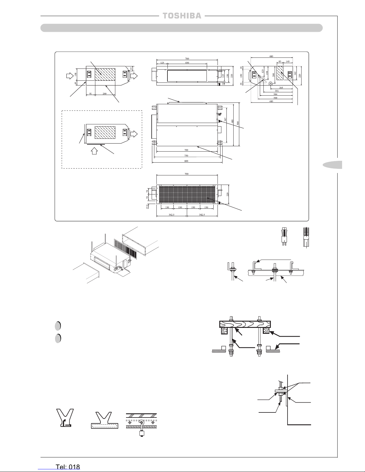
l
Check the dimensions of the unit illustrated in the following figure:
Unit Installation –
SBH Units
Connection of Ducting
Air outlet
duct (local
procurement)
Air inlet duct
(local procurement)
Shelter board
(factory fitted)
Ensure design of the air inlet duct work allows access
to replace or clean the filter.
!
The maximum static pressure of the Air Outlet duct
should not exceed 30Pa/3mmAq.
!
Hanging Unit
(1) Raise the unit by using a lift-
ing device, then secure the
hangers to the hanging
bolts. Be sure to fix the nuts
onto both the upper and
under side of the hanger
and the washer (under side
only);
(2) Install the unit horizontally
by using a level. Failure to
do this will cause water
leakages.
Nut
Hanger
Hanging
Bolt
Washer
Installation on a steel frame:
Use the angular
bracket in the
structure or install
one for support.
Cross
length
of wood
Hanging
bolt
Beam
Ceiling
Installation on a wooden structure:
Place a length of wood of the appropriate size across two
beams and install the hanging bolts into this length of wood.
Installation on an existing concrete slab:
Use hole-in anchors, hole-in plugs
or hole-in bolts for the installation.
How to Install the Hanging Bolts
Installation on a newly installed concrete slab:
Use insert brackets or foundation bolts for the installation.
Knife-shaped
bracket
Sliding
bracket
Reinforcing
bar
Foundation
bolt
(Foundation bolt for
hanging the piping)
Hanging
bolt
Angular bracket
for support
Hanger bolt
Installing Ø 10 Hanging Bolts (4 pieces)
l
Install the hanging bolts at the intervals shown in the
above figure.
l
Use Ø 10 hanging bolts (to be locally procured).
l
The filter is factory fitted to the rear of the unit as
shown above.
l
If lower air inlet is required, remove the filter and 6
screws from the shelter board, reposition shelter board
on to the rear of the unit and replace the filter.
Refrigerant pipe
connection
(Gas ø12.7)
Refrigerant pipe
connection
(Liquid ø6.4)
Washable filter
Air outlet
Air inlet
Filter
Filter
Hanging bolt pitch
Hanging bolt
pitch
Unit dimension
Unit dimension
Unit dimension
Optional Air Flow (Lower air inlet)
Shelter board
Shelter board
Air
flow
Air flow
Terminal box
wiring connections
Drain pipe connection
(1" BSP threaded
connection)
Electrical box
(PCB, Transformer and MF Capacitor)
Heronhill - for all your Toshiba requirements
Tel: 01823 665660
www.heronhill.co.uk
Fax: 01823 665807
~ 18 ~
~ 18 ~
INDOOR UNIT LOCATION
Unit Installation –
SH/SHR Units
Before Installation
(1) Take off the accessories.
Side
panel
(left)
(2)
Remove
the hanger
(left, right).
(4) Remove the side
panels by hand. Slide
them in order of
1 - 2 .
(5) Pull the air filter out then remove the inlet grille fixing
screws.
10-20mm
Detailed figure of
the hinge portion
Body
In case of removing the inlet
grille take the hinge portion off
in order of 1 - 2 .
Installing Hexagon Bolts
(accessory)
Allow a
spacing of
about
10mm
Determining installation position and direction
of the piping and wiring
BOTTOM VIEW
Knock out
Gas line connection
Liquid line
connection
Knock out
(rear
attachment)
Body
Recommended Mounting Height
l
It is recommended that the unit is mounted
150mm above the floor.
150mm or more
l The positions of the hanging bolts are printed on the
carton box (the size is not printed).
Bmm (inner hanging)
Cut the slit portion
by a saw or knife
In case of right or left attachment
Opening knock out hole
BACK VIEW
Drain connection
(OD 20mm)
Knock out
(right or left
attachment)
SIDE VIEW
Installing Ø 10 Wall Bolts
Ø Wall Bolts are procured locally
l Install wall bolts at the spacings shown below.
INNER HANGING
Hole for expanded bolt
(4 – 12 x 27 slots)
Wall bolt pitch
Bmm (Wall bolt pitch)
Amm
Model A B
164SH/SHR 1030 920
264SH/SHR 1230 1120
Side panel
(right)
l Securely fix left
and right side
panels with a
screw supplied
after unit
installation.
Inlet grille
Shipping fixture
(centre)
Slit
l The
dotted line
indicates the
rear end of the
unit. To be
detached on
the dotted line.
(3) Remove all the
metal shipping fixtures (left, corner,
centre, right corner).
Amm
Hinge
Position of hanging bolt
(ø 10 printed)
Heronhill - for all your Toshiba requirements
Tel: 01823 665660
www.heronhill.co.uk
Fax: 01823 665807
~ 19 ~
GB
~ 19 ~
INDOOR UNIT LOCATION
Unit Installation –
SH/SHR Units continued
Hanging the Indoor Unit – SH/SHR Units continued
(1) Fitting Hanger
Wall
M10
Plate washer
Double nut
(2) Fitting of Hanger
Hanger
Wall
(3) Hanging the Indoor Unit
Hexagon bolt
Hanger
(4) Fasten the Hexagon Bolts to Hang the Unit
Remote Control Cord,
SH Models only
l
Wire the cord over the refrigerant piping and the drain piping.
l
If the cord was wired under the piping, it would cause difficulty in pulling out the air filter.
40mm or less*
Hanger
Hexagon bolt
*Allow a bolt length of 40mm or less
Fix the hexagon bolts from
the unit in the hangers
Heronhill - for all your Toshiba requirements
Tel: 01823 665660
www.heronhill.co.uk
Fax: 01823 665807
~ 20 ~
~ 20 ~
INDOOR UNIT LOCATION
Unit Installation –
TUH/TUH-1, TU/TU-1 Units
Installing Ø 10 Hanging Bolts (4 pieces)
l
Install the hanging bolts at the intervals shown in the
following figure.
l
Use ø 10 hanging bolts (to be locally procured).
Ceiling preparation:
The actual procedure differs according
to the structure. Consult your builder or whoever was
responsible for the interior of the house/building.
(1)
Removal of part of the ceiling plate:
In order to ensure that the ceiling is kept perfectly
horizontal and to prevent the ceiling from vibrating the
ceiling framework must be reinforced;
(2) Cut and remove part of the ceiling framework;
(3) Reinforce the ends of the ceiling framework where it was
cut and add framework to secure the ends.
l
Some piping and wiring connections must be made in the
ceiling after the unit has been suspended. After selecting where
the unit will be installed, decide on the direction of the piping
connection. If the ceiling is already installed, prepare the
refrigerant pipes, drain pipe, indoor to outdoor unit connection
wiring and the remote control cord at the piping and wiring
connection positions before suspending the indoor unit.
How to Install the Hanging Bolts
Installation on a newly installed concrete slab:
Use insert brackets or foundation bolts for the installation.
Check the dimensions of the unit illustrated in the
following figure. Use the accompanying template for
installation and adjust the position of the body of the
unit to the position of the opening on the ceiling.
Secure the cardboard template to the body of the
indoor unit with four bolts (M5 x 20mm), supplied with
the ceiling panel.
!
!
Knife-shaped
bracket
Sliding
bracket
Reinforcing
bar
Foundation
bolt
(Foundation bolt for
hanging the piping)
Beam
Ceiling
Installation on a wooden structure:
Place a length of wood of the appropriate size across two
beams and install the hanging bolts onto this length of wood.
l
Hang the nut of
hanger bolt on the
U shape groove in
the body hanger.
l
Check the level of
the body by using a
spirit level.
Installation on an existing concrete slab:
Use hole-in anchors, hole-in plugs or hole-in bolts for the
installation.
(1) Check that the distance between the bottom of the indoor unit
and the underside of the ceiling is 3mm (four corners).
(2) Check that the distance between the side of the indoor unit
and the ceiling is 600mm (common to the left and right sides).
(3) Check that the distance between the front side of the indoor
unit (piping side) and the ceiling board is 200mm, and between
the back of the indoor unit and the ceiling is 50mm.
l
Tighten the upper nut and fix the position of the unit.
Precautions
Since the unit contains a drain pump and a float switch, the body
must be level.
If the body is installed in a tilted state the float switch will not
function properly and thus will cause water leakage.
Models TUH-1/TU-1: No drain socket is fitted to the drain pan on
the above models. If the drain pan needs to be removed after
installation and operation, ensure that the drain pan is kept level to
avoid any water from spilling over.
!
!
!
Installation of Ceiling Panel:
Install the ceiling panel following the installation manual supplied
with it.
Precautions
Before installing the ceiling panel, check that the body of the unit
has been installed correctly against the ceiling.
The ceiling panel and ceiling face must contact closely. The ceiling
panel and the contact side of the body must contact closely. Any
gap between them will cause air leakage and thus generate
condensation.
Hanging
bolt
Angular
bracket for
support
Installation on a steel
frame:
Use the angular
bracket in the
structure or install
one for support.
Hanger bolt
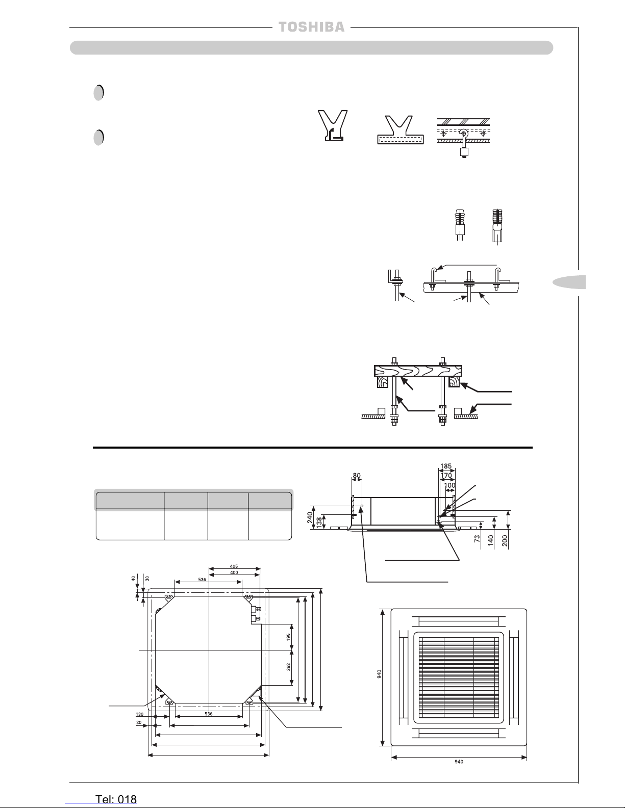
Panel outer dimension 1050
Ceiling opening 1010
Hang bolt pitch 930
840
Wiring connection
TU/TUH only
Wiring connection
TU-1/TUH-1 only
(Gas Ø 12.7)
(Liquid Ø 6.4)
(Outer Ø 25.5)
Drain pipe connection
Hanger bolt
(4- M10)
Hang bolt pitch 410
480
Ceiling opening 510
Panel outer dimension 550
Hanging Unit
l
Adjusting the positions of the nuts (lower side) so that
the distance between the washer (lower side) and the
ceiling is 140mm.
Ceiling
Nut (upper side)
Hanger
Washer (upper side)
Hanger of body
Washer (lower side)
Nut (lower side)
Hanging bolt
Cross
length of
wood
Refrigerant pipe connection
Refrigerant pipe connection
!
!
ABC
TUH/TU Units 80 290 110
TUH-1/TU-1 Units 75 330 75
Heronhill - for all your Toshiba requirements
Tel: 01823 665660
www.heronhill.co.uk
Fax: 01823 665807
~ 21 ~
GB
~ 21 ~
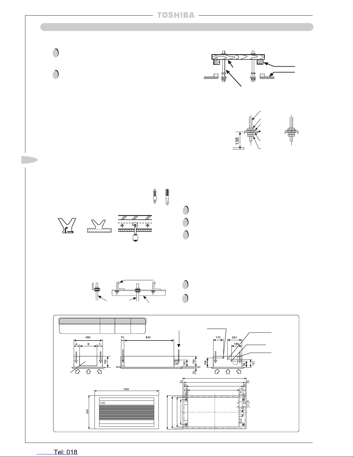
Unit Installation –
UH/U UNITS
Check the dimensions of the unit illustrated in the
following figure. Use the accompanying template for
installation and adjust the position of the body of the
unit to the position of the opening on the ceiling.
Secure the cardboard template to the body of the
indoor unit with four bolts (M5 x 20mm).
!
!
Installing Ø 10 Hanging Bolts (4 pieces)
l
Install the hanging bolts at the intervals shown in the
following figure.
l
Use Ø 10 hanging bolts (to be locally procured).
Ceiling preparation:
The actual procedure differs according
to the structure. Consult your builder or whoever was
responsible for the interior of the house/building.
(1)
Removal of part of the ceiling plate:
In order to ensure that the ceiling is kept perfectly
horizontal and to prevent the ceiling from vibrating the
ceiling framework must be reinforced;
(2) Cut and remove part of the ceiling framework;
(3) Reinforce the ends of the ceiling framework where it was
cut and add framework to secure the ends.
l
Some piping and wiring connections must be made in the
ceiling after the unit has been suspended. After selecting where
the unit will be installed, decide on the direction of the piping
connection. If the ceiling is already installed, prepare the
refrigerant pipe, drain pipe, indoor to outdoor unit connection
wiring and the remote control cord at the piping and wiring
connection positions before suspending the indoor unit.
Installation on a steel frame:
Use the angular
bracket in the
structure or install
one for support.
Cross
length
of wood
Hanging
bolt
Beam
Ceiling
Installation on a wooden structure:
Place a length of wood of the appropriate size across two
beams and install the hanging bolts into this length of wood.
Installation on an existing concrete slab:
Use hole-in anchors, hole-in plugs
or hole-in bolts for the installation.
How to Install the Hanging Bolts
Installation on a newly installed concrete slab:
Use insert brackets or foundation bolts for the installation.
Knife-shaped
bracket
Sliding
bracket
Reinforcing
bar
Foundation
bolt
(Foundation bolt for
hanging the piping)
Hanging
bolt
Angular
bracket for
support
Hanger bolt
RAV-164UH/U
RAV-264UH/U
880 (CEILING OPENING)
Wiring connection (Gland
Plate 3 x Ø20 holes)
Drain pipe connection
(1'' BSP threaded connection)
940 (PANEL DIMENSION)
Drain Pipe
(1'' BSP Threaded Connection)
820 (EXTERNAL CASSETTE DIMENSION)
800 HANGER BOLT PITCH
820 (EXTERNAL DIMENSION PITCH)
880 (CEILING OPENING)
940 (PANEL DIMENSION)
Fresh Air Inlet
620 (HANGER BOLT PITCH)
Refrigerant pipe
connection (Gas ØA)
Refrigerant pipe
connection (Liquid ØB)
Model (RAV-) 164UH/U 264U 264UH
ØA 12.7 15.9 15.9
ØB 6.4 9.5 9.5
INDOOR UNIT LOCATION
Heronhill - for all your Toshiba requirements
Tel: 01823 665660
www.heronhill.co.uk
Fax: 01823 665807
~ 22 ~
~ 22 ~
Unit Installation
– UH/U Units continued
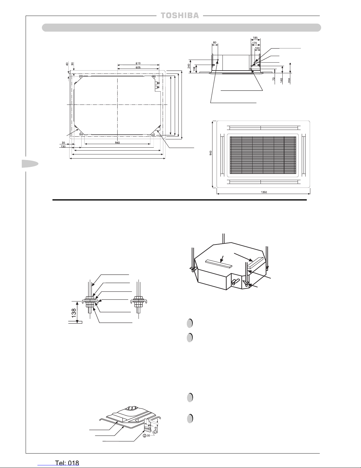
Hanging Unit
l
Adjusting the positions of the nuts (lower side) so that
the distance between the washer (lower side) and the
ceiling is 138mm.
l
Hang the nut of hanger bolt on the U shape groove in
the body hanger.
l
Check the level of the body by using a spirit level.
l
Adjust the location and height of the indoor unit in
relation to the ceiling opening by using the installation
gauge provided in the template.
(A diagram to use the part is indicated on the installation
gauge)
(1) Ensure that the distance between the bottom of the
indoor unit and the underside of the ceiling is 43mm in
all 4 corners.
(2) Ensure the gap between the side of the indoor unit and
the ceiling is 30mm all the way around.
l
Tighten the upper nut and fix the position of the unit.
Precautions
Since the unit contains a drain pump and a float switch, the
body must be level.
If the body is installed in a tilted state, the float switch will
not function properly and thus will cause water leakage.
Installation of Ceiling Panel:
Install the ceiling panel following the installation manual supplied with it.
Precautions
Before installing the ceiling panel, check that the body of
the unit has been installed correctly against the ceiling.
The ceiling panel and ceiling face must contact closely. The
ceiling panel and the contact side of the body must contact
closely. Any gap between them will cause air leakage and
thus generate condensation.
!
!
!
!
Hanger
Level
Tighten firmly
Indoor Unit
Ceiling
Installation Gauge
Hanger
Nut
Washer
Washer
Hanger
Nut
RAV-364UH/U
RAV-464UH/U
Wiring connection
(Gland Plate 3 x Ø20 holes)
Drain pipe connection
(1'' BSP threaded connection)
1290 CEILING DIMENSION
1350 PANEL DIMENSION
1230 EXTERNAL CASSETTE DIMENSION
Condensate Pipe 1'' BSP
Threaded Connection
1030 HANGER BOLT PITCH
800 HANGER BOLT PITCH
820 (EXTERNAL DIMENSION PITCH)
880 (CEILING OPENING)
940 (PANEL DIMENSION)
Fresh Air Inlet
INDOOR UNIT LOCATION
Refrigerant pipe connection
(ø19.0 Gas side)
Refrigerant pipe connection
(ø9.5 Liquid side)
Heronhill - for all your Toshiba requirements
Tel: 01823 665660
www.heronhill.co.uk
Fax: 01823 665807
~ 23 ~
GB
~ 23 ~
INDOOR UNIT LOCATION
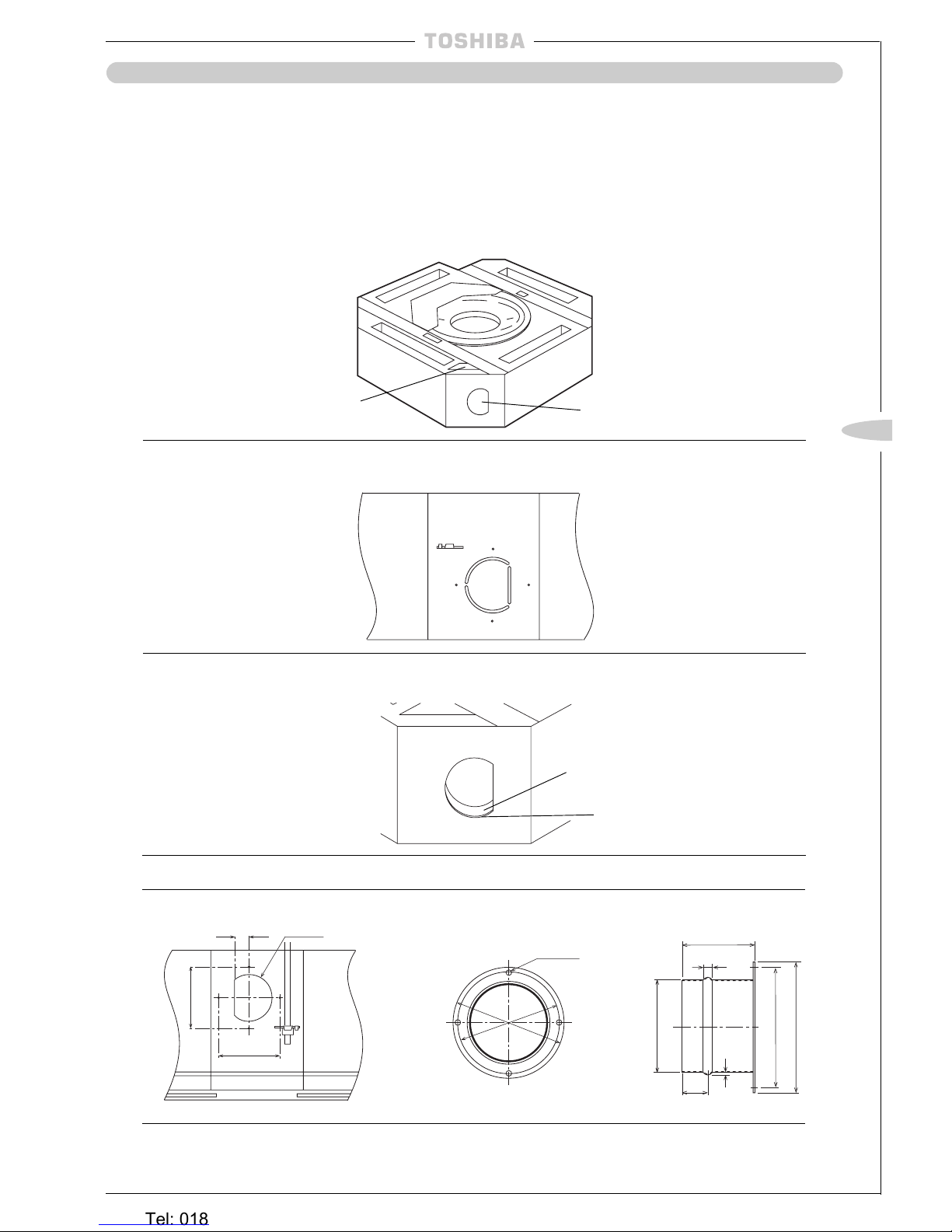
(2) Carefully cut through the slots of the ‘D’ shape with a knife ensuring the blade does not penetrate
more than 30mm.
Thermal Insulator
(5) Add a spigot to the side of the indoor unit and attach using the 4 screw holes as shown below:-
Air Inlet Spigot (ø100)
Fresh Air Inlet
Details of Cut Out Hole
(1) The cut out hole is a ‘D’ shape half-cut hole on the side of the indoor unit located on the opposite side from
the pipe work.
(3) Cut the 3 metal tabs to remove the ‘D’ shape metal part and the thermal insulator from the
indoor unit.
Metal
Fresh Air Inlet
l
These models have a cut out hole in the cabinet to enable external air to enter the indoor unit.
l
Before installing the unit, remove the cut out hole and insulation block and fit a spigot to connect the duct
before hanging the unit.
(6) Add thermal insulation around the spigot to eliminate the possibility of condensation forming on the metal sur-
faces.
Drain Pan
Insulation Block
(4) Remove the insulation block located in the drain pan, above the fresh air inlet.
32 ø100
130
130
4-ø6
ø144
ø130
80
10
30
2
ø97
ø130
ø144
Heronhill - for all your Toshiba requirements
Tel: 01823 665660
www.heronhill.co.uk
Fax: 01823 665807
~ 24 ~
~ 24 ~
INDOOR UNIT LOCATION
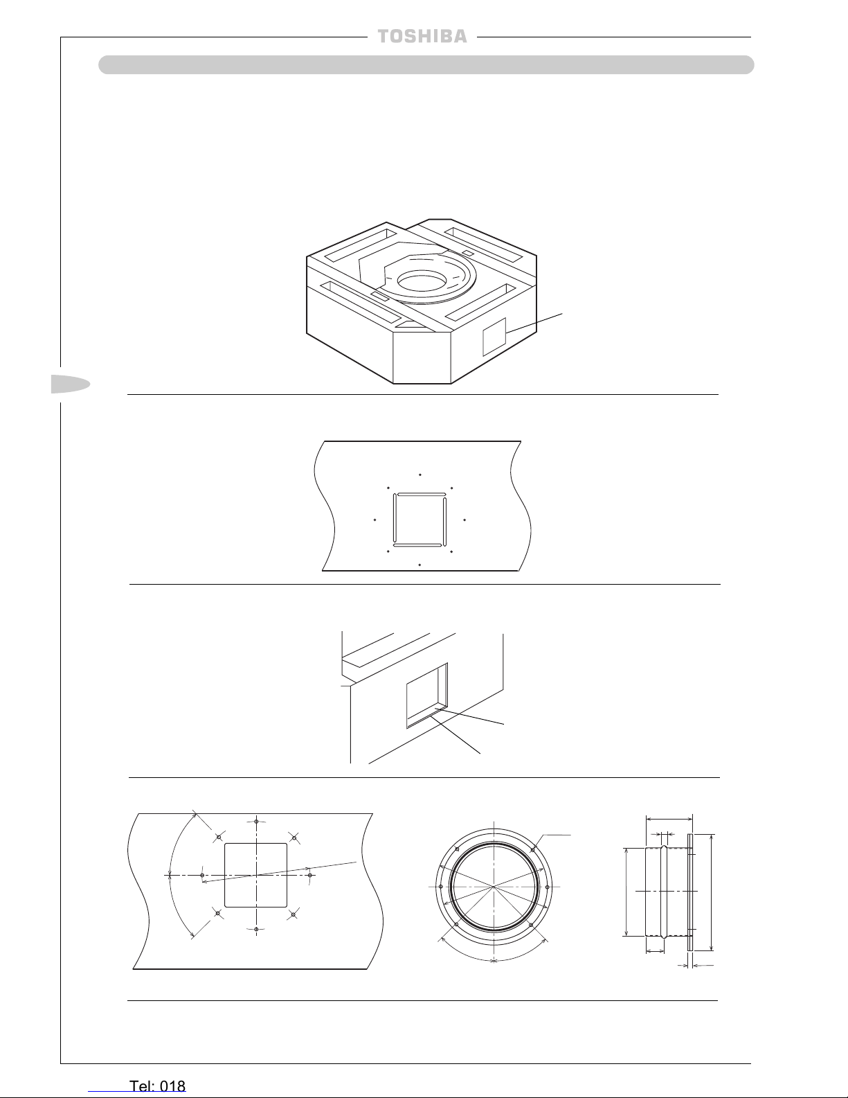
Air Outlet Duct
l
To improve air distribution in a room it is possible to divide the air outlet into the room. This is acheived by
adding a distribution duct. Only one duct can be used per unit.
l
Before installing the unit remove the cut out hole and fit a spigot to connect the duct before hanging the unit.
(2) Carefully cut through the slots of the rectangular shape with a knife ensuring the blade does not penetrate
more than 30mm.
Thermal Insulator
(4) Add a spigot to the side of the indoor unit and attach using the 6 screw holes as shown below:-
Air Outlet Spigot (ø150)
Air Outlet Duct
Details of Cut Out Hole
(1) The cut out hole is a rectangular shape half-cut hole located on two sides of the unit.
(3) Cut the 4 metal tabs to remove the rectangular metal part and the thermal insulator from the
indoor unit.
Metal
(5) Add thermal insulation around the spigot to eliminate the possibility of condensation forming on the
metal surfaces.
6-ø6
ø 180
45°
45°
ø150
6
80
10
30
ø200
45°
ø 180
45°
Heronhill - for all your Toshiba requirements
Tel: 01823 665660
www.heronhill.co.uk
Fax: 01823 665807
~ 25 ~
GB
~ 25 ~
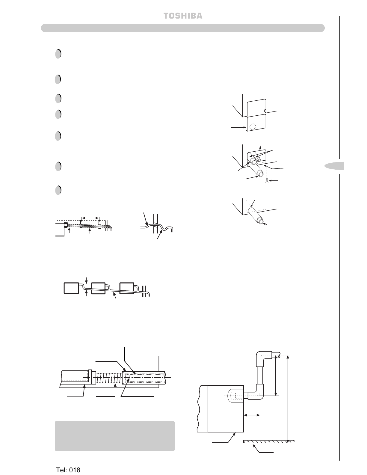
UH/U
l
Connection to the unit is via a 1’’ BSP male connection
– to ensure a waterproof seal, PTFE thread tape must
be used. The maximum lift of the condensate pump
from the drain outlet is 360mm and the maximum
overall lift from the underside of the ceiling to the centre
of the drain piping is 600mm. These values must not be
exceeded otherwise unit flooding will occur when the
drain pump is switched off.
360mm (max)
100mm
(max)
600mm (max)
Ceiling
Cassette
DRAIN PIPING
Ensure that the drain piping indoors is correctly
heat-insulated otherwise condensation will result.
Also, insulate the section which connects it to the
indoor unit.
If nylon cable ties are used to secure the insulation,
do not over-tighten them causing the deformation of
the heat insulation because this will reduce the
effectiveness of the insulation.
Use hard PVC adhesive for joining the pipes to
ensure that there will be no leakage.
Take care not to apply any force or pressure at the
unit side where the drain piping exits the indoor
unit.
The drain piping must be placed on a downward
gradient (1/100 or greater) and there should be no
upward or downward curves in the pipe which
obstruct the drainage, unless a drain pump is
employed.
The drain pipe should not extend for more than
20m horizontally. If the pipe has to be extended
horizontally for a considerable distance it must be
sufficiently supported to prevent warpage, also
increasing the gradient is recommended.
When one drainage system is used for a multiple
number of indoor units, install the piping as shown
below:
!
!
!
!
!
!
15-20m
Support clamp
Insulator
Downward gradient
1/100 or greater
Make this distance as long as possible – approx 10cm
Downward gradient
1/100 or greater
Upward
curve
Downward
curve
Piping Material and Heat Insulator
Heat Insulator*
Hard PVC pipe**
Drain pan Drain hose Hard PVC adhesive
*
Heat Insulator:
Polyethylene foam (thickness 6mm)
**
Piping Material:
Hard PVC pipe nominal diameter inside Ø20mm
Fixing the Drain Pan
CH/CHR/C
Rear Attachment
SH/SHR
Bottom Attachment
l
Screw the drain pipe fixing plate to the lower part of the
rear/bottom knockout and attach the drain pipe with the
nylon band. The knot in the nylon band should be on
the inner side (above the drain pipe fixing plate). When
the drain pipe alone is attached to the rear/bottom, use
the drain pipe knockout only.
Cut the slit
portion with a
saw
Rear/Bottom knockout
Nylon band
(supplied)
Drain Pipe
(Use the screw
from shipping
fixture)
Screw
Drain pipe
fixing plate
(supplied)
Refrigeration
pipes
CH/CHR/C
Right or Left attachment of Drain Hose
l
For attachment on the left, open up the knockout.
Attach the drain hose from right to left and the plug
from left to right. The plug is not tapered and should be
fully inserted. After attaching the pipe, seal the remaining gap in the knockout with the heat insulating material
supplied (cut to an appropriate shape).
Precautions
Drain Pipe
!
Rear knockout for drain
pipe
7
3
Heronhill - for all your Toshiba requirements
Tel: 01823 665660
www.heronhill.co.uk
Fax: 01823 665807
~ 26 ~
~ 26 ~
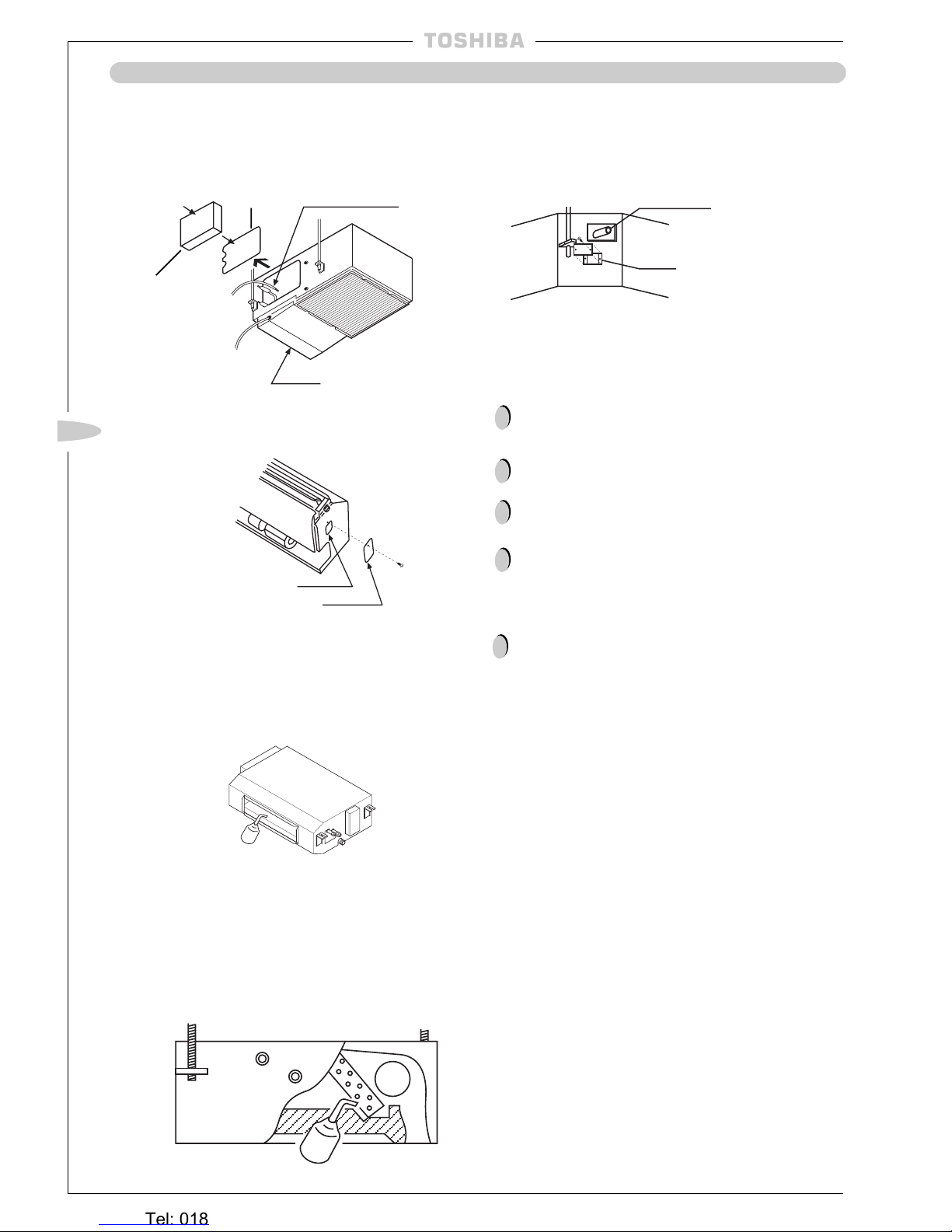
BH/B
units
l
Remove the electrical box and service panel, then pour
water on the drain pan. Confirm that the water drains
correctly.
CH/CHR/C, SH/SHR
units
l
When piping is completed pour water on the drain pan
through the inspection hole to make sure that the water
drains correctly.
Service
Panel
Drain pan
Inspection hole
Inspection cover
KH/KHR/K
units
l
It is not possible to add water the drain pan to confirm
correct drainage. To do this, the unit must be operated
in the COOL mode.
SBH
units
l
Pour 500ml water directly into the drain pan via the AirOutlet-Duct prior to additional duct work being attached
to confirm water drains correctly.
NH
units
l
Pour water into the drain catch on the side of the unit
and ensure that the water drains correctly.
TUH/TUH-1, TU/TU-1
units
l
Pour about 500ml of water into the drain pan using a
wash bottle as shown in the diagram below. Once
connection with the electric power source has been
made, test the drainage by running the unit in the
COOL mode.
500ml wash bottle
500ml wash bottle
Air-Outlet-Duct
UH/U
units
l
Remove the sevice panel located below the drain
connection as shown below. Pour about 500ml of water
into the drain pan and then operate the unit in the
COOL mode to confirm the water is removed from the
unit.
Service panel
Drain socket
Hose for pouring water
DRAIN PIPING
Precautions
The power must be applied to the unit for at least 12
hours before operating the unit. This is to ensure the
compressor is fully warmed by the heater, otherwise
the unit may malfunction.
Do not under any circumstance, force the unit to
operate by using the magnetic contactor test button.
Before conducting the Trial Run, be sure to remove all
packaging from the unit and check that the service
valves are open.
A Forcible Trial Run can be carried out, either cooling
or heating, regardless of the room temperature.
TUH/TUH-1, TU/TU-1
units only
When operating the unit for the first time, press the
LOUVER button on the remote control. This ensures
the louvers are in the correct position.
!
!
!
!
!
Wired Remote Controller
l
To execute a cooling operation Trial Run, set the
operating mode to the COOL position and keep the
ON/OFF button pressed. Temperature (L) and Fan
Speed (AUTO) will be displayed.
l
To start a heating Trial Run, set the operating mode to
HEAT position and keep the ON/OFF button pressed.
This will set temperature to H and initiate a heating Trial
Run.
l
Press the ON/OFF switch after the completion of the
Trial Run.
Electrical
box
Drainage Check
Trial Run
l
With the infra-red remote controller, only a cooling trial
run can be executed.
l
To invoke a cooling trial run, set the operation change
over switch on the infra-red receiver (on the indoor unit)
to COOL MANUAL.
l
During a trial run the operation cannot be changed by
the use of the remote controller.
l
Set the switch on the receiver to REMOTE CONTROL
after the completion of the test run.
Infra-Red Remote Controller
Heronhill - for all your Toshiba requirements
Tel: 01823 665660
www.heronhill.co.uk
Fax: 01823 665807
~ 27 ~
GB
REFRIGERANT PIPING
Precautions for R407C Outdoor Units
R407C outdoor units use synthetic oils which are extremely hygroscopic. Therefore ensure that
the refrigerant system is NEVER exposed to air or any form of moisture.
Mineral oils are unsuitable for use in these units and may lead to premature system failure.
Use only equipment which is suitable for use with R407C. Never use equipment which has been
used with R22.
R407C should only be charged from the service cylinder in the liquid phase. It is advisable to use
a gauge manifold set equipped with a liquid sight glass fitted in the centre (entry) port.
!
!
!
!
Material and Sizes
Materials and pipes required for connection between the indoor and outdoor units.
Piping material:
Seamless, deoxidised copper piping for air conditioning (refrigeration quality tube).
!
If models RAV-364AH8/A8; 464AH8/A8 are installed with a pipe length of more than 30m, the diameter
of the gas pipe must be increased to Ø22.2mm (
7
/
8
").
!
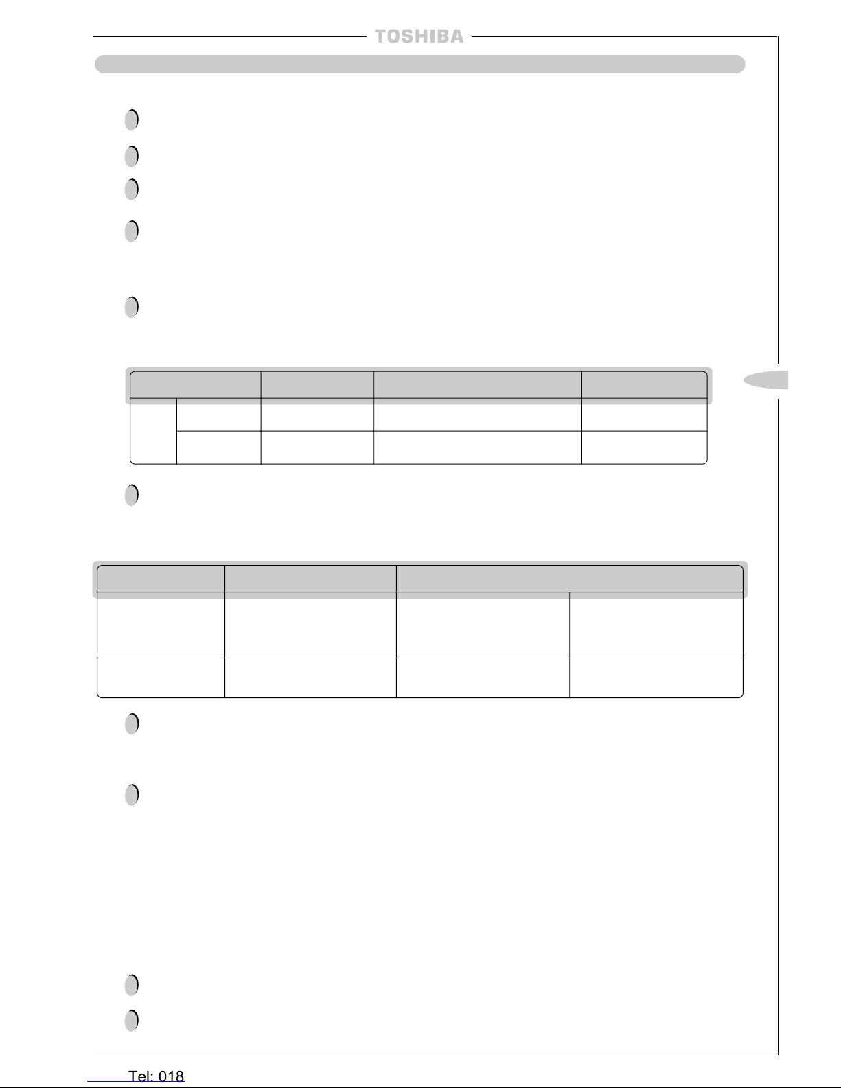
Permissible Piping Length and Head
Model (RAV-)
134AH/A
164AH/A
264AH/AH8/A/A8
364AH8/A8
464AH8/A8
The maximum piping length from the
outdoor unit to the indoor unit
The maximum height difference from the outdoor unit to the indoor unit –
When the outdoor unit is above
When the outdoor unit is below
30m 30m 15m
50m 50m 20m
Limit the total number of bends in the pipework to 10 or less.
When installing the pipework it is essential that the following points are adhered to:
(i) Cleanliness is essential – keep the pipework securely sealed at all times during the installation.
(ii) No sight glass should be fitted to the liquid pipe.
(iii) Do not incorporate an oil trap in vertical pipework.
(iv) Displace all air with oxygen-free-nitrogen.
!
!
Pipework Installation
When removing air and dehydrating refrigerant pipework, use an approved type of vacuum pump
only. Do NOT use the factory charge to purge the air.
Ensure a vacuum is drawn at -76cmHg (-1.013 x 10⁵Pa) at both the liquid and gas sides.
!
System Purging
!
Model (RAV-) 134/164AH/A 264A/A8 264AH/AH8 364/464AH8/A8
Gas side Ø12.7mm (
1
/
2
") Ø15.9mm (
5
/
8
") Ø19.0mm (
3
/
4
")
Liquid side Ø6.4mm (
1
/
4
") Ø9.5mm (
3
/
8
") Ø9.5mm (
3
/
8
")
Piping
Size
Heronhill - for all your Toshiba requirements
Tel: 01823 665660
www.heronhill.co.uk
Fax: 01823 665807
~ 28 ~
REFRIGERANT PIPING
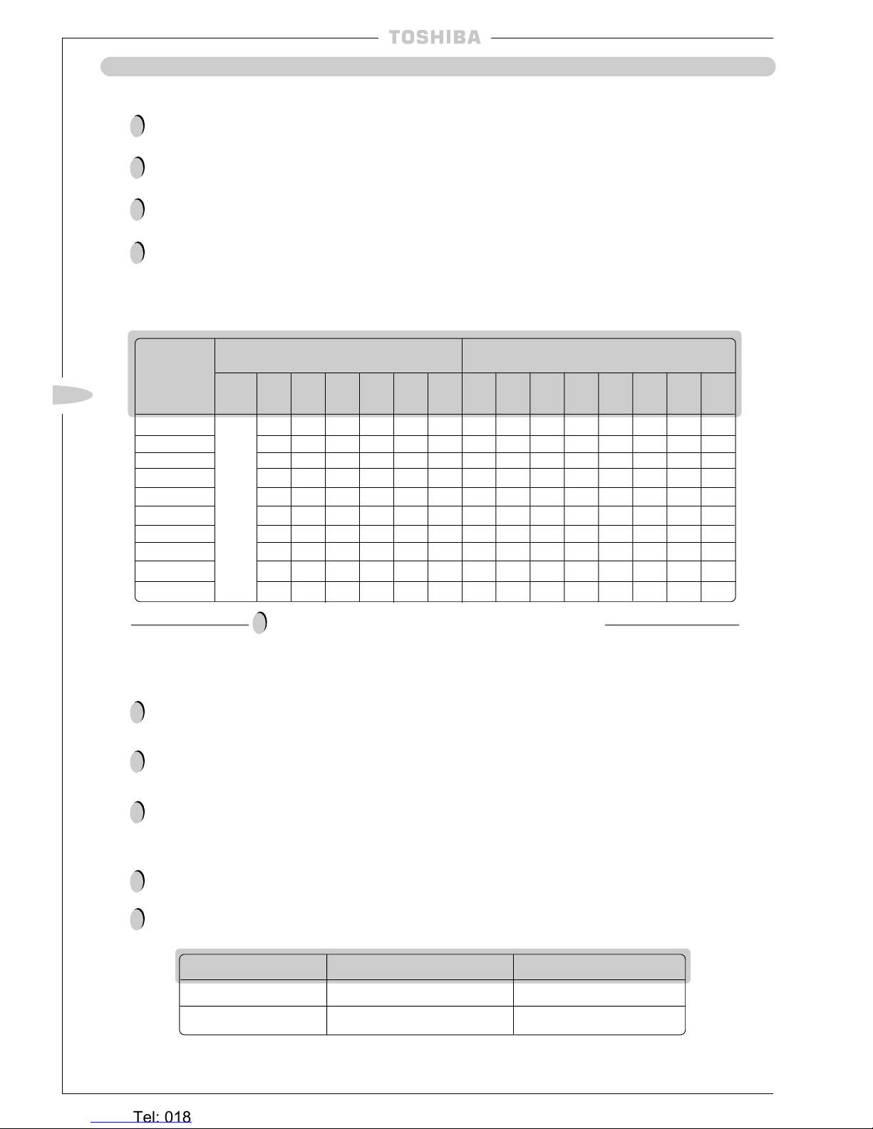
Additional Refrigerant
The amount of refrigerant put into the outdoor unit at the factory is sufficient to fill up to 20m of
refrigerant pipework.
If the length of the refrigerant pipework is 20m or less, addition of refrigerant at the installation site
is unnecessary.
If the length of the pipework exceeds 20m, extra refrigerant must be added. Refer to the table
below for details of the extra amounts.
Overcharge or undercharge of refrigerant in the outdoor unit will cause malfunction of
the compressor.
The prescribed amount of the replenishment of the refrigerant is shown in the table below:
!
!
!
!
134AH-PE
164AH-PE
264AH/AH8-PE
364AH8-PE
464AH8-PE
134A-PE
164A-PE
264A/A8-PE
364A8-PE
464A8-PE
0.18 0.35 — — — — 0.79 1.05 1.23 1.4 — — — —
0.18 0.35 — — — — 0.94 1.2 1.38 1.55 — — — —
0.18 0.35 — — — — 1.64 1.9 2.08 2.25 — — — —
0.18 0.35 0.53 0.7 0.88 1.05 2.44 2.7 2.88 3.05 3.23 3.4 3.58 3.75
0.25 0.5 0.75 1.0 1.25 1.5 3.13 3.5 3.75 4.0 4.25 4.5 4.75 5.0
0.18 0.35 — — — — 0.79 1.05 1.23 1.4 — — — —
0.18 0.35 — — — — 0.94 1.2 1.38 1.55 — — — —
0.18 0.35 — — — — 1.64 1.9 2.08 2.25 — — — —
0.18 0.35 0.53 0.7 0.88 1.05 2.44 2.7 2.88 3.05 3.23 3.4 3.58 3.75
0.25 0.5 0.75 1.0 1.25 1.5 3.13 3.5 3.75 4.0 4.25 4.5 4.75 5.0
ADD ONLY R407C REFRIGERANT TO THESE UNITS
!
Heat Insulation
Provide heat insulation on the refrigerant piping on both the liquid side and gas side separately,
and ensure that all joints in the insulation are vapour sealed.
Since the temperature of the piping on the gas side increases during heating operations, the heat
insulating material used must be able to withstand temperatures of more than 120˚C –
HEAT PUMP TYPES ONLY.
Use the pipe insulation supplied in the accessory pack to insulate the piping connecting section on
the indoor unit side.
!
!
!
Pressure Measurement
Connect the pressure gauge to the locations in the table below when measuring the pressure during operation.
A gauge is required since check joints are used for the connecting sections.
!
!
High-pressure side Low-pressure side
During cooling Check joint in the outdoor unit Gas side packed valve
During heating Gas side packed valve Check joint in outdoor unit
Note: During cooling operation, the pressure in the packed valve on the liquid side reduces.
MODEL
(RAV-)
Recharge amount if unit is reclaimed
(kg)
±50g
Less
than
5m
Less
than
20m
Less
than
25m
Less
than
30m
Less
than
35m
Less
than
40m
Less
than
45m
Less
than
50m
Additional amount of refrigerant to add at
installation site (kg)±50g
Less
than
20m
Less
than
25m
Less
than
30m
Less
than
35m
Less
than
40m
Less
than
45m
Less
than
50m
Filled
at
Factory
Heronhill - for all your Toshiba requirements
Tel: 01823 665660
www.heronhill.co.uk
Fax: 01823 665807
~ 29 ~
GB
~ 29 ~
Precautions
This guide should be read and utilised in conjunction with the official published regulations and
codes of practice, be they local, national or international.
Each air conditioning system will have its own discrete power supply, with overload current
protection.
Install a multi-pole isolation switch (with 3mm separation) in the power supply circuit.
The current protective device will prevent and protect the supply cable against overcurrent.
The circuit protection must be selected having due regard to the compressor starting current, such
that the supply cables when sized correctly, are also protected.
The cable should be selected to match the nominal load of the system, in addition to the losses
associated with corrections for length, temperature, impedance, etc. In accordance with local
codes of practice.
Earth both the indoor and the outdoor units by attaching an Earth wire. Ensure this is carried out
according to National Wiring Regulations.
After having made the connection to the terminal board, secure the cables with a cable clamp.
Wiring for the power supply must be performed by a qualified electrical engineer or technician
only.
Do not allow the cables (used for the power supply and for wiring between the units) to come into
contact with valves or pipes not covered with insulators. Secure these cables to the parts of the
pipes with heat insulation fitted.
Use the Ø20mm knockouts provided on the units (except KH/KHR/K), to fit cable glands to hold
the cables securely at the point where they enter the electrical box or unit.
!
!
!
!
!
!
!
!
!
!
!
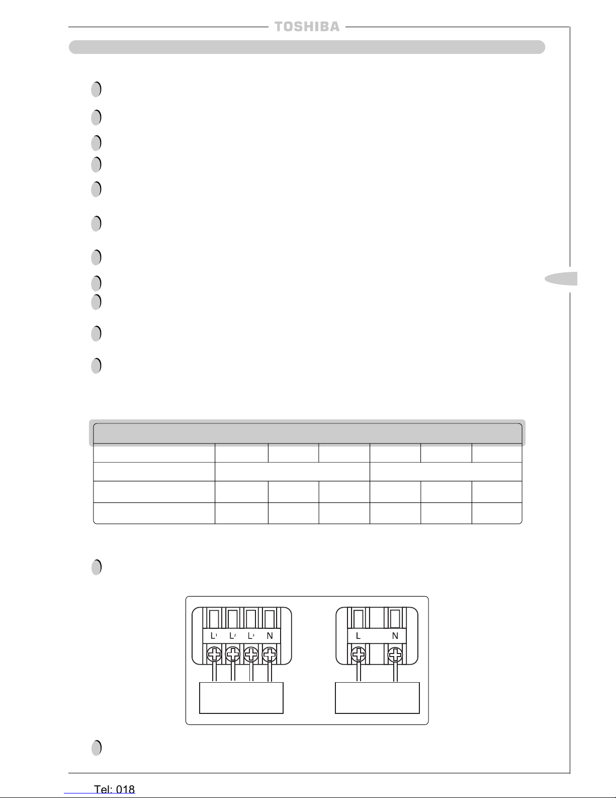
Power Supply Specifications
Power Supply Wiring
For a 3-phase model (4 wires), connect the power wiring to the L1, L2, L3 and N terminals on the
power supply terminal block of the outdoor unit. For a single phase model, connect the power
wiring to the L and N terminals (
see drawing below
):
380/415V 50Hz
3 phase 4 wires
220/240V 50Hz
Single phase
!
Models RAV-264AH8/A8, RAV-364AH8/A8, RAV-464AH8/A8 are equipped with a reverse phase
protector. If the compressor does not start, interchange phase L2 with phase L3 of the power supply.
!
ELECTRICAL WIRING
Main Circuit
Model (RAV–) 134AH/A 164AH/A 264AH/A 264AH8/A8 364AH8/A8 464AH8/A8
Power Supply 220/240V – 1PH – 50Hz 380/415V – 3PH – 50Hz
Starting current (A) 60 60 80 25 42 50
Running current (A) 10.7 11.1 14.8 4.7 6.8 8.5
Heronhill - for all your Toshiba requirements
Tel: 01823 665660
www.heronhill.co.uk
Fax: 01823 665807
~ 30 ~
~ 30 ~
ELECTRICAL WIRING
Wiring Between Units
Connect the wires between the units correctly. Errors made in the connections can result in the
unit malfunctioning.
Connect the control wires between the outdoor unit and indoor unit as shown in the figure below:
!
!
Connect the central
remote controller here
(OPTION)
Connect the remote
controller here
(OPTION)
Connect wiring between
indoor and outdoor unit here
Connecting the Remote Controller —
BH, CH, KH, NH, SBH, SH, TUH, TUH-1, UH only
Any standard 3-core cable operating at 12VAC with a cross-sectional area ranging from 0.3mm2to
0.75mm2and with a maximum length of 500 metres can be used.
When routing this cable, care should be taken to ensure that it is not in direct contact with mains
cable or routed in duct or conduit containing power cables.
Connect the terminals A, B and C on the remote controller with the terminals A, B and C on the
indoor unit terminal block, ensuring that the terminals are matched up correctly.
Full instructions on the setting and operation of this controller are included in the owner’s manual,
supplied with the remote controller.
!
!
!
!
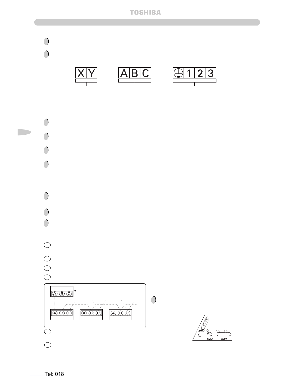
Group Control –
BH, CH, KH, NH, SBH, SH, TUH, TUH-1, UH only
Up to 16 air conditioners can be controlled as a group using a single remote controller. (The
control circuit for each indoor unit originates at the outdoor unit from the incoming phase
connection marked L or L1. It is important that on a group system that all the control circuits
throughout the group are derived from the same phase.)
No parts (except for the connecting cable) are required for group control.
Proceed with the power cable connections and with the wiring connections between the indoor
and outdoor units in exactly the same way as for individual air conditioner operation.
Connect the remote controller and the indoor unit in the following sequence:
1
Connect together the terminals A, B and C on both the remote controller and indoor unit No.1
ensuring that the terminals are matched up correctly;
2
Connect together terminals B and C on indoor units No.1 and No.2;
3
Connect together terminals B and C on indoor units No.2 and No.3;
4
Proceed in the same way to make the necessary connections up to indoor unit No.16;
!
!
!
Remote controller
Indoor unit (No.1)
Indoor unit Indoor unit
(No.2 – No.16)
Precautions
Use cables with a cross-sectional area of at
least 0.75mm2to connect the indoor units. The
maximum length of 500 metres for the remote
controller cable denotes the maximum length
from the remote controller to the furthest
indoor unit.
!
5
Leave the (CN12) connector in unit No.1 but remove
from any further indoor units to prevent malfunction due to miswiring.
6
Set the rotary switch position on each indoor unit to a different number, starting with position 1 for
unit No.1 which is connected to the remote controller. This will also ensure that each unit will start
up at a slightly different time therefore ensuring no increase in start-up current.
(Indoor unit terminal blocks)
Heronhill - for all your Toshiba requirements
Tel: 01823 665660
www.heronhill.co.uk
Fax: 01823 665807
 Loading...