

Toshiba ras-m10g3dv-nd, ras-m13g3dv-e, ras-m13g3dv-nd, ras-m16g3dv-nd, ras-m07g3dv-nd Service Manual
...
SERVICE MANUAL
AIR-CONDITIONER
MULTI-SPLIT TYPE
Indoor unit
FILE NO. A10-1413
Revision 1 : Mar.2015
RAS-M07G3DV-E
RAS-M10G3DV-E
RAS-M13G3DV-E
RAS-M16G3DV-E
RAS-M07G3DV-ND
RAS-M10G3DV-ND
RAS-M13G3DV-ND
RAS-M16G3DV-ND
RAS-M07G3DV-TR
RAS-M10G3DV-TR
RAS-M13G3DV-TR
RAS-M16G3DV-TR
R410A

CONTENTS
1.SAFETY PRECAUTIONS................................................................................ 2
2. SPECIFICATIONS.......................................................................................... 5
3. REFRIGERANT R410A .................................................................................. 6
4. CONSTRUCTION VIEWS............................................................................. 14
5. WIRING DIAGRAM....................................................................................... 15
6. SPECIFICATIONS OF ELECTRICAL PARTS............................................. 16
7. REFRIGERANT CYCLE DIAGRAM............................................................. 17
8. CONTROL BLOCK DIAGRAM .................................................................... 18
9. OPERATION DESCRIPTION ....................................................................... 19
10. OWNER’S MANUAL and INSTALLATION MANUAL (EXCERPT)........... 44
11. HOW TO DIAGNOSE THE TROUBLE....................................................... 61
12. HOW TO REPLACE THE MAIN PARTS.................................................... 75
13. EXPLODED VIEWS AND PARTS LIST..................................................... 85
14. Appendix.................................................................................................... 88
– 1 –
1.SAFETY PRECAUTIONS
The important contents concerned to the safety are described on the product itself and on this Service Manual.
Please read this Service Manual after understanding the described items thoroughly in the following contents
(Indications / Illustrated marks), and keep them.
[Explanation of indications]
Indication Explanation
DANGER
WARNING
CAUTION
∗ Property damage: Enlarged damage concerned to property, furniture, and domestic animal / pet
[Explanation of illustrated marks]
Mark Explanation
Indicates prohibited items (Forbidden items to do)
The sentences near an illustrated mark describe the concrete prohibited contents.
Indicates mandatory items (Compulsory items to do)
The sentences near an illustrated mark describe the concrete mandatory contents.
Indicates cautions (Including danger / warning)
The sentences or illustration near or in an illustrated mark describe the concrete cautious
contents.
Indicates contents assumed that an imminent danger causing a death or serious injury of
the repair engineers and the third parties when an incorrect work has been executed.
Indicates possibilities assumed that a danger causing a death or serious injury of the
repair engineers, the third parties, and the users due to troubles of the product after work
when an incorrect work has been executed.
Indicates contents assumed that an injury or property damage (∗) may be caused on the
repair engineers, the third parties, and the users due to troubles of the product after work
when an incorrect work has been executed.
For general public use
Power supply cord of outdoor unit shall be more than 2.5 mm² (H07RN-F or 60245IEC66) polychloroprene
sheathed flexible cord.
• Read this “Safety precautions” carefully before servicing.
• The precautions described below include the important items regarding safety. Observe them without fail.
• After the servicing work, perform a test run to check for any problem.
• Turn off the main power supply switch (or breaker) before the unit maintenance.
CAUTION
New refrigerant air conditioner installation
• This air conditioner adopts the new HFC refrigerant (R410A) which does not destroy ozone layer.
R410A refrigerant is apt to be affected by impurities such as water, oxidizing membrane, and oils because the
working pressure of R410A refrigerant is approx. 1.6 times of refrigerant R22. Accompanied with the adoption
of the new refrigerant, the refrigeration machine oil has also been changed. Therefore, during installation work,
be sure that water, dust, former refrigerant, or refrigeration machine oil does not enter into the new type
refrigerant R410A air conditioner circuit.
To prevent mixing of refrigerant or refrigerating machine oil, the sizes of connecting sections of charging port on
main unit and installation tools are different from those used for the conventional refrigerant units.
Accordingly, special tools are required for the new refrigerant (R410A) units. For connecting pipes, use new and
clean piping materials with high pressure fittings made for R410A only, so that water and/or dust does not enter.
Moreover, do not use the existing piping because there are some problems with pressure fittings and possible
impurities in existing piping.
– 2 –
CAUTION
To disconnect the appliance from the main power supply
A switch or circuit breaker that can disconnect all poles must be included in the fixed wiring.
Be sure to use an approved circuit breaker or switch.
DANGER
• The manufacturer shall not assume any liability for the damage caused by not observing the
description of this manual.
• Ask an authorized dealer or qualified installation professional to install / maintain the air conditioner.
Inappropriate servicing may result in water leakage, electric shock or fire.
• Turn off main power supply before attempting any electrical work.
Make sure all power switches are off. failure to do so may cause electric shock.
DANGER: HIGH VOLTAGE
The high voltage circuit is incorporated. Be careful to do the check service, as the electric shock may be caused
in case of touching parts on the P.C. board by hand.
• Correctly connect the connecting cable. if the connecting cable is incorrectly connected, electric parts may be
damaged.
• Check that the earth wire is not broken or disconnected before service and installation. Failure to do so may
cause electric shock.
• Do not install near concentrations of combustible gas or gas vapors. Failure to follow this instruction can result
in fire or explosion.
• To prevent the indoor unit from overheating and causing a fire hazard, place the unit well away (more than 2 m)
from heat sources such as radiators, heat resistors, furnace, stoves, etc.
• When moving the air-conditioner for installation in another place, be very careful not to allow the specified
refrigerant (R410A) to become mixed with any other gaseous body into the refrigeration circuit. if air or any
other gas is mixed in the refrigerant, the gas pressure in the refrigeration circuit will become abnormally high
and it may result in the pipe bursting and possible personnel injuries.
• In the event that the refrigerant gas leaks out of the pipe during the service work and the installation work,
immediately let fresh air into the room. If the refrigerant gas is heated, such as by fire, generation of poisonous
gas may result.
WARNING
• Do not use any refrigerant different from the one specified for complement or replacement.
Otherwise, abnormally high pressure may be generated in the refrigeration cycle, which may result in a failure
or explosion of the product or an injury to your body.
• Never modify this unit by removing any of the safety guards or bypass any of the safety interlock
switches.
• Do not install in a place which cannot bear the weight of the unit.
Personal injury and property damage can result if the unit falls.
• After the installation work, confirm that refrigerant gas does not leak.
If refrigerant gas leaks into the room and flows near a fire source such as a cooking range, noxious gas may
generate.
• The electrical work must be performed by a qualified electrician in accordance with the Installation
Manual. Make sure the air conditioner uses an exclusive circuit.
An insufficient circuit capacity or inappropriate installation may cause fire.
• When wiring, use the specified cables and connect the terminals securely to prevent external forces
applied to the cable from affecting the terminals.
• Be sure to provide grounding.
Do not connect ground wires to gas pipes, water pipes, lightning rods or ground wires for telephone cables.
• Conform to the regulations of the local electric company when wiring the power supply.
Inappropriate grounding may cause electric shock.
• Do not modify the products. Do not also disassemble or modify the parts. It may cause a fire, electric shock or
injury.
– 3 –

• Exchange to parts specified in service manual, which meet the specification or listed in parts list of service
manual.
Failure to use specified parts may result in electrical shock, smoke, and/or fire."
• When checking the electric parts, removing the cover of the electric parts box of Indoor Unit and/or front panel
of Outdoor Unit inevitably to determine the failure, put a sign “Do not enter” around the site before the work.
Failure to do this may result in third person getting electric shock.
• When performing repairs using a gas burner, replace the refrigerant with nitrogen gas because the oil that coats
the pipes may otherwise burn. When repairing the refrigerating cycle, take the following measures.
1)Be attentive to fire around the cycle. When using a gas stove, etc., be sure to put out fire before work;
otherwise the oil mixed with refrigerant gas may catch fire.
2)Do not use a welder in the closed room. When using it without ventilation, carbon monoxide poisoning may
be caused.
3)Do not bring inflammable close to the refrigerant cycle, otherwise fire of the welder may catch the
inflammable.
• Once the repair work has been completed, check for refrigerant leaks, and check the insulation resistance and
water drainage. If check is not executed, a fire, electric shock, injury or water leakage may be caused.
• Install the access port (ceiling opening) at least 2.5 m above the floor level and attach the grille (locally
procured) to the air intake section since otherwise the users may injure themselves or receive electric shocks if
they poke their fingers or other objects into the indoor unit while the air conditioner is running.
CAUTION
• Exposure of unit to water or other moisture before installation may result in an electrical short.
Do not store in a wet basement or expose to rain or water.
• Do not install in a place that can increase the vibration of the unit. Do not install in a place that can amplify the
noise level of the unit or where noise or discharged air might disturb neighbors.
• To avoid personal injury, be careful when handling parts with sharp edges.
• Perform the specified installation work to guard against an earthquake.
If the air conditioner is not installed appropriately, accidents may occur due to the falling unit.
– 4 –

2. SPECIFICATIONS
Model Name
Cooling capacity (Rated) [kW] 2.0 2.7 3.7 4.5
Cooling Capacity range [kW] *1 *1 *1 *1
Heating Capacity (Rated) [kW] 2.7 4.0 5.0 5.5
Heating Capacity range [kW] *1 *1 *1 *1
Power supply 1Phase, 50Hz, 220-240V / 1Phase, 60Hz, 220V
Electric
characteristics
*2
External Static Pressure Setting 4steps (10 / 20 / 35 / 45)
Air flow [m3/h]
Sound
pressure
level
[dBA]*3
Fan Unit
Dimensions *4
Net weight [kg] 16 19
Piping
connection
Usable indoor temperature range
(Cooling / Heating)
Voltage [V] 220 230 240 220 230 240 220 230 240 220 230 240
Running current
[A]
Power
Consumption [W]
Power Factor [%]62626262
Cooling
Heating
Cooling
Back air intake
Heating
Cooling
Under air intake
Heating
Fan centrifugal fan
Motor Output [W] 94
Height [mm] 210
Width [mm] 700 900
Depth [mm] 450
Type Flare connection
Liquid side [mm] 6.35
Gas side [mm] 9.52 12.7
Drain port VP25
RAS-M07G3DV-E RAS-M10G3DV-E RAS-M13G3DV-E RAS-M16G3DV-E
RAS-M07G3DV-ND RAS-M10G3DV-ND RAS-M13G3DV-ND RAS-M16G3DV-ND
RAS-M07G3DV-TR RAS-M10G3DV-TR RAS-M13G3DV-TR RAS-M16G3DV-TR
0.35 0.34 0.32 0.35 0.34 0.32 0.40 0.38 0.36 0.45 0.43 0.42
48 48 54 62
10Pa 20Pa 35Pa 45Pa 10Pa 20Pa 35Pa 45Pa 10Pa 20Pa 35Pa 45Pa 10Pa 20Pa 35Pa 45Pa
HH 570 570 610 780
H+ 525 525 555 720 670 690 690
H 475 475 500 580 540 590 600
L+ 430 430 440 500 490 490 560
L 380 380 385 420
HH 570 570 610 780
H+ 525 525 555 720 670 690 690
H 475 475 500 580 540 590 600
L+ 430 430 440 510 490 490 560
L 380 380 385 450
HH 33 34 35 36 33 34 35 36 35 36 37 38 33 34 35 36
H+ 31 32 33 34 31 32 33 34 32 33 34 35 31 31 32 33
H 29303132293031322930313227272931
L+ 27 28 29 30 27 28 29 30 27 28 29 30 24 25 26 29
L 25262728252627282526272822232425
HH 33 34 35 36 33 34 35 36 35 36 37 38 33 34 35 36
H+ 31 32 33 34 31 32 33 34 32 33 34 35 31 31 32 33
H 29303132293031322930313227272931
L+ 27 28 29 30 27 28 29 30 27 28 29 30 25 25 26 29
L 25262728252627282526272823242526
HH 41 42 43 44 41 42 43 44 43 44 45 46 41 42 43 44
H+ 38 39 40 41 38 39 40 41 39 40 41 42 39 39 40 41
H 35363738353637383637383934343638
L+ 33 34 35 36 33 34 35 36 33 34 35 36 31 32 33 36
L 30313233303132333031323327282930
HH 41 42 43 44 41 42 43 44 43 44 45 46 41 42 43 44
H+ 38 39 40 41 38 39 40 41 39 40 41 42 39 39 40 41
H 35363738353637383637383934343638
L+ 33 34 35 36 33 34 35 36 33 34 35 36 32 32 33 36
L 30313233303132333031323328293031
21~32°C / 0~28°C
*1 … Refer to the service manual of the outdoor unit to be combined.
*2 … Electrical charasteristics is under FAN ONLY mode HH tap at 35Pa.
*3 … Under standard external static pressure line at each pressure setting.
*4 … Unit external dimension (except hanging hook)
– 5 –

3. REFRIGERANT R410A
This air conditioner adopts the new refrigerant HFC
(R410A) which does not damage the ozone layer.
The working pressure of the new refrigerant R410A is
1.6 times higher than conventional refrigerant (R22).
The refrigerating oil is also changed in accordance with
change of refrigerant, so be careful that water, dust,
and existing refrigerant or refrigerating oil are not
entered in the refrigerant cycle of the air conditioner
using the new refrigerant during installation work or
servicing time.
The next section describes the precautions for air
conditioner using the new refrigerant. Conforming to
contents of the next section together with the general
cautions included in this manual, perform the correct
and safe work.
3-1.Safety During Installation/Servicing
As R410A’s pressure is about 1.6 times higher than
that of R22, improper installation/servicing may cause
a serious trouble. By using tools and materials
exclusive for R410A, it is necessary to carry out
installation/servicing safely while taking the following
precautions into consideration.
1. Never use refrigerant other than R410A in an airc
onditioner which is designed to operate with R410A.
If other refrigerant than R410A is mixed, pressure in
the refrigeration cycle becomes abnormally high,
and it may cause personal injury, etc. by a rupture.
2. Confirm the used refrigerant name, and use tools
and materials exclusive for the refrigerant R410A.
The refrigerant name R410A is indicated on the
visible place of the outdoor unit of the air conditioner
using R410A as refrigerant. To prevent mischarging,
the diameter of the service port differs from that of
R22.
3. If a refrigeration gas leakage occurs during
installation/servicing, be sure to ventilate fully.
If the refrigerant gas comes into contact with fire, a
poisonous gas may occur.
4. When installing or removing an air conditioner, do
not allow air or moisture to remain in the refrigeration
cycle. Otherwise, pressure in the refrigeration cycle
may become abnormally high so that a rupture or
personal injury may be caused.
5. After completion of installation work, check to make
sure that there is no refrigeration gas leakage.
If the refrigerant gas leaks into the room, coming into
contact with fire in the fan-driven heater, space
heater, etc., a poisonous gas may occur.
6. When an air conditioning system charged with a
large volume of refrigerant is installed in a small
room, it is necessary to exercise care so that, even
when refrigerant leaks, its concentration does not
exceed the marginal level.
If the refrigerant gas leakage occurs and its
concentration exceeds the marginal level, an oxygen
starvation accident may result.
7. Be sure to carry out installation or removal according
to the installation manual.
Improper installation may cause refrigeration trouble,
water leakage, electric shock, fire, etc.
8. Unauthorized modifications to the air conditioner
may be dangerous. If a breakdown occurs please
call a qualified air conditioner technician or
electrician.
Improper repair’s may result in water leakage,
electric shock and fire, etc.
3-2. Refrigerant Piping Installation
3-2-1.Piping Materials and Joints Used
For the refrigerant piping installation, copper pipes and
joints are mainly used. Copper pipes and joints suitable
for the refrigerant must be chosen and installed.
Furthermore, it is necessary to use clean copper pipes
and joints whose interior surfaces are less affected by
contaminants.
1.Copper Pipes
It is necessary to use seamless copper pipes which
are made of either copper or copper alloy and it is
desirable that the amount of residual oil is less than
40 mg/10 m. Do not use copper pipes having a
collapsed, deformed or discolored portion (especially
on the interior surface).
Otherwise, the expansion valve or capillary tube may
become blocked with contaminants.
As an air conditioner using R410A incurs pressure
higher than when using R22, it is necessary to
choose adequate materials.
Thicknesses of copper pipes used with R410A are
as shown in Table 3-2-1. Never use copper pipes
thinner than 0.8 mm even when it is available on the
market.
– 6 –

Table 3-2-1 Thicknesses of annealed copper pipes
Thickness (mm)
Nominal diameter Outer diameter (mm) R410A R22
1/4 6.35 0.80 0.80
3/8 9.52 0.80 0.80
1/2 12.70 0.80 0.80
5/8 15.88 1.00 1.00
2.Joints
For copper pipes, flare joints or socket joints are used. Prior to use, be sure to remove all contaminants.
a) Flare Joints
Flare joints used to connect the copper pipes cannot be used for pipings whose outer diameter exceeds 20
mm. In such a case, socket joints can be used.
Sizes of flare pipe ends, flare joint ends and flare nuts are as shown in Tables 3-2-3 to 3-2-6 below.
b) Socket Joints
Socket joints are such that they are brazed for connections, and used mainly for thick pipings whose
diameter is larger than 20 mm.
Thicknesses of socket joints are as shown in Table 3-2-2.
Table 3-2-2 Minimum thicknesses of socket joints
Nominal diameter
1/4 6.35 0.50
3/8 9.52 0.60
1/2 12.70 0.70
5/8 15.88 0.80
Reference outer diameter of
copper pipe jointed (mm)
Minimum joint thickness
(mm)
3-2-2. Processing of Piping Materials
When performing the refrigerant piping installation, care should be taken to ensure that water or dust does not
enter the pipe interior, that no other oil than lubricating oils used in the installed air-water heat pump is used, and
that refrigerant does not leak. When using lubricating oils in the piping processing, use such lubricating oils whose
water content has been removed. When stored, be sure to seal the container with an airtight cap or any other
cover.
1.Flare processing procedures and precautions
a) Cutting the Pipe
By means of a pipe cutter, slowly cut the pipe so that it is not deformed.
b) Removing Burrs and Chips
If the flared section has chips or burrs, refrigerant leakage may occur.
Carefully remove all burrs and clean the cut surface before installation.
c) Insertion of Flare Nut
– 7 –
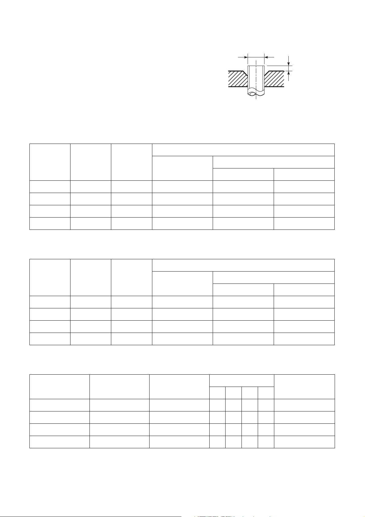
d) Flare Processing
Make certain that a clamp bar and
copper pipe have been cleaned.
By means of the clamp bar, perform the
flare processing correctly.
Use either a flare tool for R410A or
conventional flare tool.
Flare processing dimensions differ
according to the type of flare tool. When
using a conventional flare tool, be sure
to secure “dimension A” by using a
gauge for size adjustment.
Table 3-2-3 Dimensions related to flare processing for R410A
ØD
A
Fig. 3-2-1 Flare processing dimensions
Nominal
diameter
Outer
diameter
(mm)
Thickness
(mm)
Flare tool for R410A
clutch type
Conventional flare tool
Clutch type Wing nut type
1/4 6.35 0.8 0 to 0.5 1.0 to 1.5 1.5 to 2.0
3/8 9.52 0.8 0 to 0.5 1.0 to 1.5 1.5 to 2.0
1/2 12.70 0.8 0 to 0.5 1.0 to 1.5 2.0 to 2.5
5/8 15.88 1.0 0 to 0.5 1.0 to 1.5 2.0 to 2.5
Table 3-2-4 Dimensions related to flare processing for R22
A (mm)
A (mm)
Nominal
diameter
Outer
diameter
(mm)
Thickness
(mm)
Flare tool for R22
clutch type
Conventional flare tool
Clutch type Wing nut type
1/4 6.35 0.8 0 to 0.5 0.5 to 1.0 1.0 to 1.5
3/8 9.52 0.8 0 to 0.5 0.5 to 1.0 1.0 to 1.5
1/2 12.70 0.8 0 to 0.5 0.5 to 1.0 1.5 to 2.0
5/8 15.88 1.0 0 to 0.5 0.5 to 1.0 1.5 to 2.0
Table 3-2-5 Flare and flare nut dimensions for R410A
Nominal
diameter
Outer diameter
(mm)
Thickness
(mm)
Dimension (mm)
ABCD
Flare nut width
(mm)
1/4 6.35 0.8 9.1 9.2 6.5 13 17
3/8 9.52 0.8 13.2 13.5 9.7 20 22
1/2 12.70 0.8 16.0 16.6 12.9 23 26
5/8 15.88 1.0 19.0 19.7 16.0 25 29
– 8 –
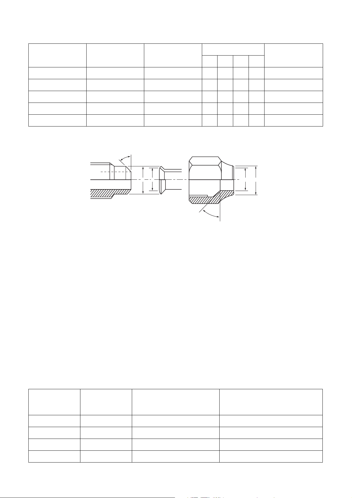
Table 3-2-6 Flare and flare nut dimensions for R22
Nominal
diameter
Outer diameter
(mm)
Thickness
(mm)
Dimension (mm)
ABCD
Flare nut width
1/4 6.35 0.8 9.0 9.2 6.5 13 17
3/8 9.52 0.8 13.0 13.5 9.7 20 22
1/2 12.70 0.8 16.0 16.2 12.9 20 24
5/8 15.88 1.0 19.0 19.7 16.0 23 27
3/4 19.05 1.0 23.3 24.0 19.2 34 36
°
6
4
o
t
°
5
4
B A
4
3
°
t
o
4
5
°
D
C
(mm)
Fig. 3-2-2 Relations between flare nut and flare seal surface
2.Flare Connecting Procedures and Precautions
a) Make sure that the flare and union portions do not have any scar or dust, etc.
b) Correctly align the processed flare surface with the union axis.
c) Tighten the flare with designated torque by means of a torque wrench. The tightening torque for R410A is
the same as that for conventional R22. Incidentally, when the torque is weak, the gas leakage may occur.
When it is strong, the flare nut may crack and may be made non-removable. When choosing the tightening
torque, comply with values designated by manufacturers. Table 3-2-7 shows reference values.
NOTE :
When applying oil to the flare surface, be sure to use oil designated by the manufacturer.
If any other oil is used, the lubricating oils may deteriorate and cause the compressor to burn out.
Table 3-2-7 Tightening torque of flare for R410A [Reference values]
Nominal
diameter
Outer diameter
(mm)
Tightening torque
N•m (kgf•cm)
Tightening torque of torque
wrenches available on the market
N•m (kgf•cm)
1/4 6.35 14 to 18 (140 to 180) 16 (160), 18 (180)
3/8 9.52 33 to 42 (330 to 420) 42 (420)
1/2 12.70 50 to 62 (500 to 620) 55 (550)
5/8 15.88 63 to 77 (630 to 770) 65 (650)
– 9 –
3-3. Tools
3-3-1. Required Tools
The service port diameter of packed valve of the outdoor unit in the air-water heat pump using R410A is changed
to prevent mixing of other refrigerant. To reinforce the pressure-resisting strength, flare processing dimensions
and opposite side dimension of flare nut (For Ø12.7 copper pipe) of the refrigerant piping are lengthened.
The used refrigerating oil is changed, and mixing of oil may cause a trouble such as generation of sludge,
clogging of capillary, etc. Accordingly, the tools to be used are classified into the following three types.
1. Tools exclusive for R410A (Those which cannot be used for conventional refrigerant (R22))
2. Tools exclusive for R410A, but can be also used for conventional refrigerant (R22)
3. Tools commonly used for R410A and for conventional refrigerant (R22)
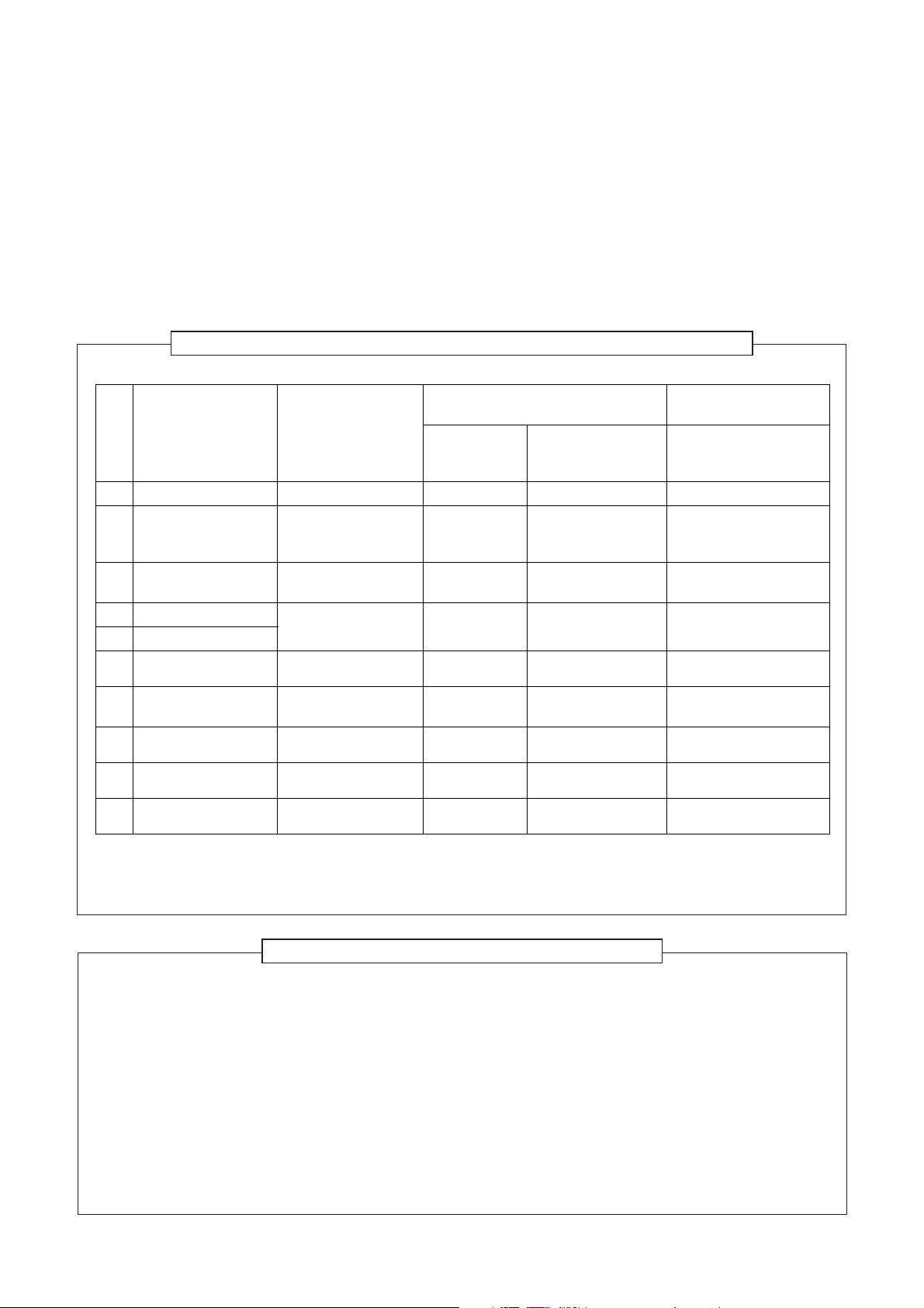
The table below shows the tools exclusive for R410A and their interchangeability.
Tools exclusive for R410A (The following tools for R410A are required.)
Tools whose specifications are changed for R410A and their interchangeability
R410A
air-water heat pump installation
No. Used tool Usage
1 Flare tool Pipe flaring Yes *(Note 1) O
Copper pipe gauge for
2
adjusting projection
margin
Torque wrench
3
(For Ø12.7)
4 Gauge manifold
5 Charge hose
6 Vacuum pump adapter Vacuum evacuating Yes
Electronic balance for
7
refrigerant charging
8 Refrigerant cylinder Refrigerant charge Yes
9 Leakage detector Gas leakage check Yes
10 Charging cylinder Refrigerant charge (Note 2)
Flaring by
conventional flare tool
Connection of flare nut Yes
Evacuating, refrigerant
charge, run check, etc.
Refrigerant charge Yes
Existence of
new equipment
for R410A
Yes *(Note 1) *(Note 1)
Whether conventio nal
equipment can be
used
××
Yes
××
×
×
××
×
××
Conventional air-water
heat pump installation
Whether new equipment
can be used with
conventional refrigerant
O
O
O
(Note 1) When flaring is carried out for R410A using the conventional flare tools, adjustment of projection
margin is necessary. For this adjustment, a copper pipe gauge, etc. are necessary.
(Note 2) Charging cylinder for R410A is being currently developed.
General tools (Conventional tools can be used.)
In addition to the above exclusive tools, the following equipments which serve also for R22 are necessary
as the general tools.
1. Vacuum pump
Use vacuum pump by attaching
vacuum pump adapter.
2. Torque wrench (For Ø6.35, Ø9.52)
3. Pipe cutter
4. Reamer
5. Pipe bender
6. Level vial
7. Screwdriver (+, –)
8. Spanner or Monkey wrench
9. Hole core drill (Ø65)
10. Hexagon wrench
(Opposite side 4mm)
11. Tape measure
12. Metal saw
Also prepare the following equipments for other installation method and run check.
1. Clamp meter
2. Thermometer
3. Insulation resistance tester
4. Electroscope
– 10 –
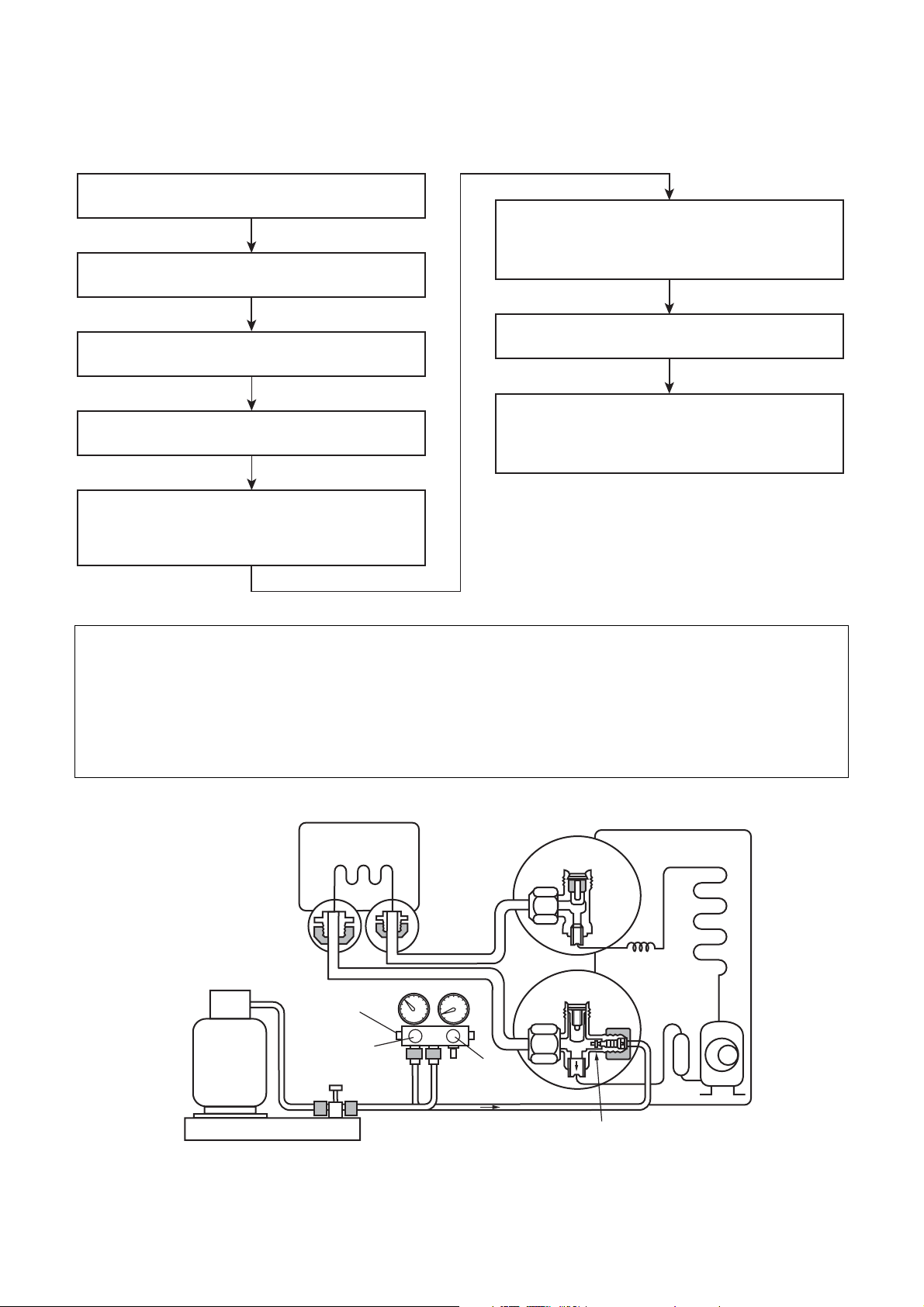
3-4. Recharging of Refrigerant
When it is necessary to recharge refrigerant, charge the specified amount of new refrigerant according to the
following steps.
Recover the refrigerant, and check no refrigerant
remains in the equipment.
Connect the charge hose to packed valve service
port at the outdoor unit’s gas side.
Connect the charge hose to the vacuum pump
adapter.
Open fully both packed valves at liquid and gas
sides.
When the compound gauge’s pointer has indicated
–0.1 Mpa (–76 cmHg), place the handle Low in the
fully closed position, and turn off the vacuum
pump’s power switch.
Keep the status as it is for 1 to 2 minutes, and ensure
that the compound gauge’s pointer does not return.
Set the refrigerant cylinder to the electronic balance,
connect the connecting hose to the cylinder and the
connecting port of the electronic balance, and
charge liquid refrigerant.
Place the handle of the gauge manifold Low in the
fully opened position, and turn on the vacuum
pump’s power switch. Then, evacuating the
refrigerant in the cycle.
(For refrigerant charging, see the figure below.)
1. Never charge refrigerant exceeding the specified amount.
2. If the specified amount of refrigerant cannot be charged, charge refrigerant bit by bit in COOL mode.
3. Do not carry out additional charging.
When additional charging is carried out if refrigerant leaks, the refrigerant composition changes in the
refrigeration cycle, that is characteristics of the air conditioner changes, refrigerant exceeding the specified
amount is charged, and working pressure in the refrigeration cycle becomes abnormally high pressure, and
may cause a rupture or personal injury.
(Indoor Unit)
Opened
(Outdoor unit)
Refrigerant cylinder
(with siphon)
Check valve
Opened
Open/close valve
for charging
Electronic balance for refrigerant charging
Fig. 3-4-1 Configuration of refrigerant charging
Opened
Closed
Service port
– 11 –
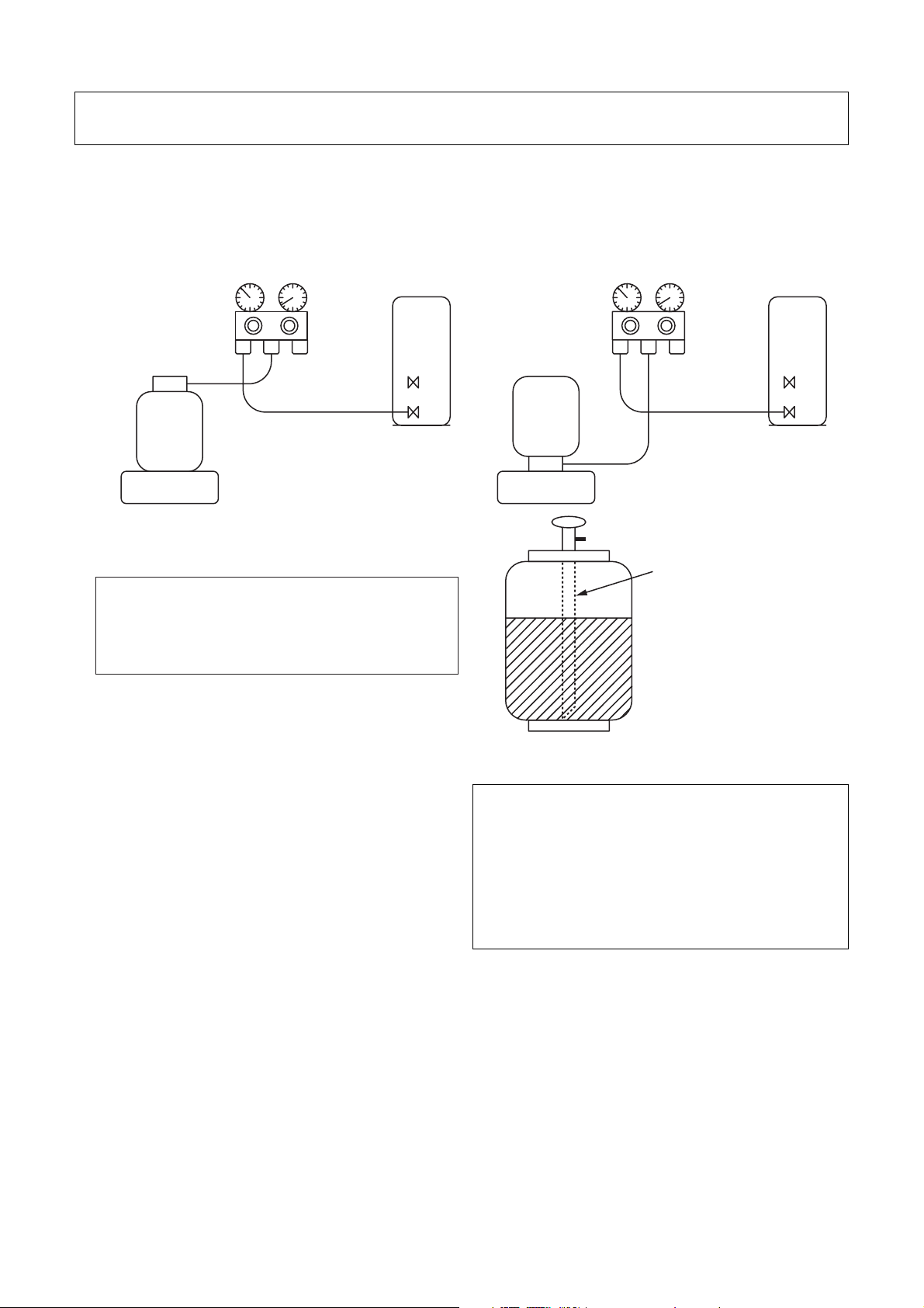
1. Be sure to make setting so that liquid can be charged.
2. When using a cylinder equipped with a siphon, liquid can be charged without turning it upside down.
It is necessary for charging refrigerant under condition of liquid because R410A is mixed type of refrigerant.
Accordingly, when charging refrigerant from the refrigerant cylinder to the equipment, charge it turning the
cylinder upside down if cylinder is not equipped with siphon.
[ Cylinder with siphon ]
Gauge manifold
OUTDOOR unit
Refrigerant
cylinder
Electronic
balance
R410A refrigerant is HFC mixed refrigerant.
Therefore, if it is charged with gas, the
composition of the charged refrigerant changes
and the characteristics of the equipment varies.
[ Cylinder without siphon ]
Gauge manifold
OUTDOOR unit
cylinder
Refrigerant
Electronic
balance
Siphon
3-5. Brazing of Pipes
3-5-1. Materials for Brazing
1.Silver brazing filler
Silver brazing filler is an alloy mainly composed of
silver and copper. It is used to join iron, copper or
copper alloy, and is relatively expensive though it
excels in solderability.
2.Phosphor bronze brazing filler
Phosphor bronze brazing filler is generally used to
join copper or copper alloy.
3.Low temperature brazing filler
Low temperature brazing filler is generally called
solder, and is an alloy of tin and lead. Since it is
weak in adhesive strength, do not use it for
refrigerant pipes.
Fig. 3-4-2
1. Phosphor bronze brazing filler tends to react with
sulfur and produce a fragile compound water
solution, which may cause a gas leakage.
Therefore, use any other type of brazing filler at a
hot spring resort, etc., and coat the surface with a
paint.
2. When performing brazing again at time of
servicing, use the same type of brazing filler.
3-5-2. Flux
1.Reason why flux is necessary
• By removing the oxide film and any foreign matter
on the metal surface, it assists the flow of brazing
filler.
• In the brazing process, it prevents the metal
surface from being oxidized.
• By reducing the brazing filler’s surface tension, the
brazing filler adheres better to the treated metal.
– 12 –

2.Characteristics required for flux
• Activated temperature of flux coincides with the
brazing temperature.
• Due to a wide effective temperature range, flux is
hard to carbonize.
• It is easy to remove slag after brazing.
• The corrosive action to the treated metal and
brazing filler is minimum.
• It excels in coating performance and is harmless to
the human body.
As the flux works in a complicated manner as
described above, it is necessary to select an
adequate type of flux according to the type and
shape of treated metal, type of brazing filler and
brazing method, etc.
3.Types of flux
• Noncorrosive flux
Generally, it is a compound of borax and boric acid.
It is effective in case where the brazing
temperature is higher than 800°C.
• Activated flux
Most of fluxes generally used for silver brazing are
this type.
It features an increased oxide film removing
capability due to the addition of compounds such
as potassium fluoride, potassium chloride and
sodium fluoride to the borax-boric acid compound.
4.Piping materials for brazing and used brazing
filler/flux
3-5-3. Brazing
As brazing work requires sophisticated techniques,
experiences based upon a theoretical knowledge, it
must be performed by a person qualified.
In order to prevent the oxide film from occurring in the
pipe interior during brazing, it is effective to proceed
with brazing while letting dry Nitrogen gas (N2) flow.
Never use gas other than Nitrogen gas.
1.Brazing method to prevent oxidation
1) Attach a reducing valve and a flow-meter to the
Nitrogen gas cylinder.
2) Use a copper pipe to direct the piping material,
and attach a flow-meter to the cylinder.
3) Apply a seal onto the clearance between the
piping material and inserted copper pipe for
Nitrogen in order to prevent backflow of the
Nitrogen gas.
4) When the Nitrogen gas is flowing, be sure to keep
the piping end open.
5) Adjust the flow rate of Nitrogen gas so that it is
lower than 0.05 m
3
/Hr or 0.02 MPa (0.2kgf/cm2)
by means of the reducing valve.
6) After performing the steps above, keep the
Nitrogen gas flowing until the pipe cools down to
a certain extent (temperature at which pipes are
touchable with hands).
7) Remove the flux completely after brazing.
Piping material Used brazing filler Used flux
Copper - Copper Phosphor copper Do not use
Copper - Iron Silver Paste flux
Iron - Iron Silver Vapor flux
1. Do not enter flux into the refrigeration cycle.
2. When chlorine contained in the flux remains
within the pipe, the lubricating oil deteriorates.
Therefore, use a flux which does not contain
chlorine.
3. When adding water to the flux, use water which
does not contain chlorine (e.g. distilled water or
ion-exchange water).
4. Remove the flux after brazing.
M
Flow meter
Stop valve
Nitrogen gas
cylinder
From Nitrogen cylinder
Pipe
Rubber plug
Nitrogen
gas
Fig. 3-5-1 Prevention of oxidation during brazing
– 13 –
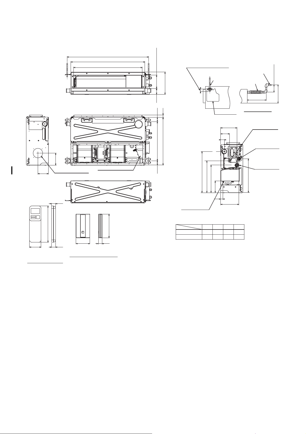
4. CONSTRUCTION VIEWS
Hanging bolt pitch A
Unit external dimension B
C (Outside)
25 or less
125(Outside)
210
dimension
Unit external
56
22
40
(Only the position of a
check cover.)
Hanging
bolt
Check cover
1/100 or more
downward
Flexible drain hose
(Accessory)
300 or less
Drain-up piping
177 or less
350 or less
113
100
57.5
WIRELESS REMOTE
CONTROLLER
Φ90 knockout hole
(For air taking-in air)
19.7
172
18
Electrical control box
120
70 18.5
SIGNAL RECEIVING UNIT
Hanging bolt pitch 370
40
Unit external dimension 450
388
300
Wires
drawing-out port
M07~13G3DV 770
M16G3DV
AB
970 900 850 1450
260
110
37
700
155
85
35
173
CD
650
Refrigerant pipe
connecting port
(Liquid side)
Drain pipe
connecting port
Refrigerant pipe
connecting port
(Gas side)
320
1250
– 14 –
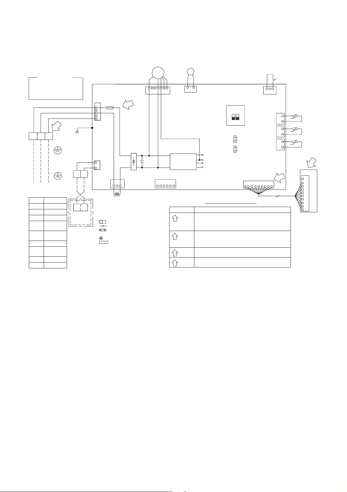
Color Indication
RED:RED
WHI:WHITE
YEL:YELLOW
BRW:BROWN
TB01
23
1
EARTH
CONNECTION
CABLE
1ø220-240V~, 50Hz
1ø 220V~, 60Hz
Symbol Parts name
CN** Connector
F01 Fuse
FM Fan Motor
TA
TB01,02
TC,TCJ Temp.sensor
DM
FS Float Switch
EARTH
Indoor
temp.sensor
Terminal
Block
Drain pump
Motor
LReactor
BLU:BLUE
BLK:BLACK
GRN:GREEN
2
TB02
Wired remote
controller
(Option)
BLK
WHI
RED
CN22
BLK
BLK
BLK
AB
AB
5. WIRING DIAGRAM
CN210
F01
T6.3A
250V~
1
3
3
5
CN67
(BLK)
CN41
1
(BLU)
2
CN01
3
1
(BLU)
L
1. Broken line indicate the wiring at site.
Long dashed short dashed line indicate the
accessories.
2. indicates the terminal block.
indicates the connection terminal.
indicates the connector on the control
P.C.board.
3. indicates the protection ground.
4. indicates the control P.C.board.
(WHI)
154
+
+
-
MS
FM
䎖䱊
3296
7
Main P.C.Board
MCC-1643
Power
supply
circuit
CN61(YEL)
123456
T10 (HA)
Check Items Diagnosis result
1
OPERATION
indicater
2
3
4
DM
M
12
CN504
(WHI)
SW501
(External static
pressure setup)
ON
21
CN71
(CHK)
(DISP)
DC20V
DC15V
DC12V
DC 7V
CN72
CN214(WHI)
354612
Quick check for diagnosing faults
Check to see if the OPERATION indicater goes on & off
when the main switch or circuit breakers turned on,or power
cord is plugged in the wall outlet.
Check for the voltage between A and B is 220 to 240VAC.
Terminal
Check for the voltage between B and C is 15 to 60VDC.
block
Fuse
Check Varistor if the fuse is open.
6.3A
Check for the voltage between G and F terminal of CN214.
DC5V
1
CN34
(RED)
CN104
(YEL)
CN102
(RED)
CN101
(BLK)
789
FS
3
1
t°
2
1
2
1
2
TA
t°
TCJ
t°
TC
1
4
10
9
8
7
6
5
4
3
12
Signal receiving unit
– 15 –

6. SPECIFICATIONS OF ELECTRICAL PARTS
Model RAS-M***G3DV* M07 M10 M13 M16
Fan motor ICF-340WD94-3 or ICF-340WD94-4
Drain pump motor MDP-1401
Float switch FS-1A-31
P.C. board MCC-1643
TA sensor Lead wire length : 328mm Vinyl tube
TC sensor Ø6 size lead wire length : 1000mm Vinyl tube (Black)
TCJ sensor Ø6 size lead wire length : 1000mm Vinyl tube (Red)
– 16 –
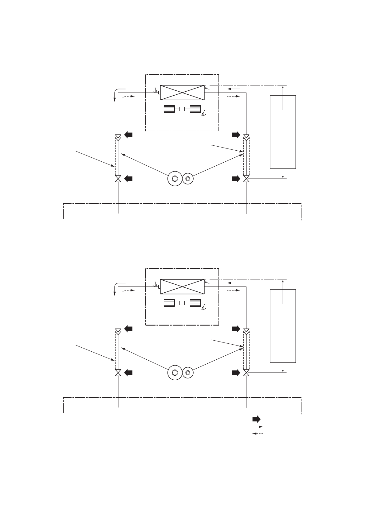
RAS-M07,10,13G3DV
7. REFRIGERANT CYCLE DIAGRAM
INDOOR UNIT
Evaporator
Tcj
Multi-blade fan
Tc
Ta
Connecting pipe
Thickness : 0.8mm
Ø9.52
RAS-M16G3DV
Connecting pipe
Thickness : 0.8mm
Ø6.35
Sectional shape
of heat insulator
OUTDOOR UNIT
INDOOR UNIT
Evaporator
Tcj
Multi-blade fan
Allowable pipe length
Allowable height difference
Tc
Ta
Connecting pipe
Thickness : 0.8mm
Ø12.7
Connecting pipe
Thickness : 0.8mm
Ø6.35
Allowable pipe length
Allowable height difference
Sectional shape
of heat insulator
OUTDOOR UNIT
NOTE : Gas leak check position
Refrigerant flow (Cooling)
Refrigerant flow (Heating)
• The allowable pipe length, charge amount of refrigerant, and allowable height difference differ according to the
outdoor unit to be combined.
For details, refer to the service manual of the outdoor unit to be combined.
– 17 –
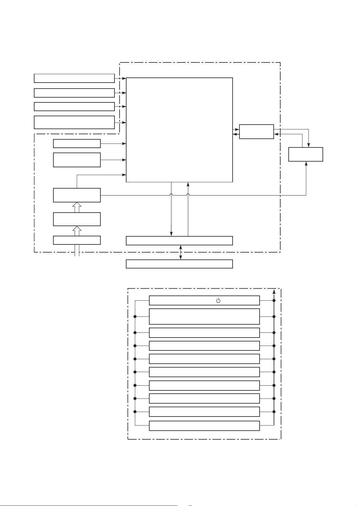
8. CONTROL BLOCK DIAGRAM
Heat Exchanger Sensor (Tcj)
Heat Exchanger Sensor (Tc)
Room Temperature Sensor (Ta)
Infrared Rays Signal Receiver
and Indication
Initializing Circuit
Clock Frequency
Oscillator Circuit
Power Supply
Circuit
Converter
(D.C circuit)
Noise Filter
M.C.U.
Functions
• Cold draft preventing Function
• 3-minute Delay at Restart for
Compressor
• Fan Motor Starting Control
•Processing
(Temperature Processing)
•Timer
• Serial Signal Communication
• Clean Function
Serial Signal Transmitter/Receiver
Indoor Unit Control Unit
Indoor Fan
Motor Control
Indoor
Fan Motor
Power Supply
(From Outdoor Unit)
REMOTE CONTROLLER
Serial Signal Communication
(Operation Command and Information)
Remote Controller
Operation [ ]
Operation Mode Selection
AUTO, COOL, DRY, FAN ONLY
Thermo. Setting
Fan Speed Selection
ON TIMER Setting
OFF TIMER Setting
ECO
Hi-POWER
COMFORT SLEEP
QUIET
Infrared Rays, 36.7kHz
– 18 –

9. OPERATION DESCRIPTION
9-1. Outline of Air Conditioner Control.............................................................................20
9-2. Operation Description.................................................................................................21
1. Basic operation ..............................................................................................................21
1-1. Operation control ....................................................................................................21
1-2. When power supply is reset....................................................................................22
1-3. Operating mode selection when performing 2-room operation...............................22
1-4. Cooling/Heating operation ......................................................................................23
1-5. AUTO operation......................................................................................................24
1-6. DRY operation ........................................................................................................24
2. Indoor fan motor control .................................................................................................25
3. Capacity control .............................................................................................................28
4. Release protective control by temperature of indoor heat exchanger............................28
5. Drain pump control.........................................................................................................29
6. After-heat elimination .....................................................................................................29
7. Intermittent Operation Control for Indoor Fans of the Indoor Unit at Thermo-off Side in
Heating Operation ..............................................................................................................30
8. Additional Operation.......................................................................................................31
8-1. QUIET mode...........................................................................................................31
8-2. Hi-POWER Mode....................................................................................................31
8-3. ECO mode ..............................................................................................................31
8-4. COMFORT SLEEP mode .......................................................................................32
9. One-Touch Comfort .......................................................................................................32
10. Temporary operation....................................................................................................32
11. Frequency fixed operation (Test run)...........................................................................33
12. Self-Cleaning function ..................................................................................................34
13. Self-Cleaning function release .....................................................................................35
14. Suction temperature correction ....................................................................................35
15. Remote-A or B selection ..............................................................................................36
16. Short Timer ..................................................................................................................36
17. External static pressure settings ..................................................................................37
9-3. Auto Restart Function.................................................................................................38
9-3-1. How to Set the Auto Restart Function .....................................................................38
9-3-2. How to Cancel the Auto Restart Function................................................................39
9-3-3. Power Failure During Timer Operation ....................................................................39
9-4. Remote control............................................................................................................40
9-4-1. Remote control and its functions .............................................................................40
9-4-2. Operation of remote control.....................................................................................40
9-4-3. Name and Functions of Indications on Remote Controller ......................................43
– 19 –

9-1. Outline of Air Conditioner Control
This air conditioner is a capacity-variable type air
conditioner, which uses DC motor for the indoor fan
motor and the outdoor fan motor. And the
capacityproportional control compressor mounted. The
DC motor drive circuit is mounted to the indoor unit.
The compressor and the inverter to control fan motor
are mounted to the outdoor unit.
The entire air conditioner is mainly controlled by the
indoor unit controller.
The indoor unit controller drives the indoor fan motor
based upon command sent from the remote controller,
and transfers the operation command to the outdoor
unit controller.
The outdoor unit controller receives operation
command from the indoor unit side, and controls the
outdoor fan and the pulse motor valve. (P.M.V)
Besides, detecting revolution position of the
compressor motor, the outdoor unit controller controls
speed of the compressor motor by controlling output
voltage of the inverter and switching timing of the
supply power (current transfer timing) so that motors
drive according to the operation command.
And then, the outdoor unit controller transfers reversely
the operating status information of the outdoor unit to
control the indoor unit controller.
As the compressor adopts four-pole brushless DC
motor, the frequency of the supply power from
inverter to compressor is two-times cycles of the
actual number of revolution.
1.Role of indoor unit controller
The indoor unit controller judges the operation
commands from the remote controller and assumes
the following functions.
• Judgment of suction air temperature of the indoor
heat exchanger by using the indoor temp. sensor.
(TA sensor)
• Judgment of the indoor heat exchanger
temperature by using heat exchanger sensor (TC
sensor) (Prevent-freezing control, etc.)
• Indoor fan motor operation control
• LED (Light Emitting Diode) display control
• Transferring of operation command signal (Serial
signal) to the outdoor unit
• Reception of information of operation status (Serial
signal including outside temp. data) to the outdoor
unit and judgment/display of error
2.Role of outdoor unit controller
Receiving the operation command signal (Serial
signal) from the indoor unit controller, the outdoor
unit performs its role.
• Detection of inverter input current and current
release operation
• Over-current detection and prevention operation to
IGBT module (Compressor stop function)
• Compressor and outdoor fan stop function when
serial signal is off (when the serial signal does not
reach the board assembly of outdoor control by
trouble of the signal system)
• Transferring of operation information (Serial signal)
from outdoor unit controller to indoor unit controller
• Detection of outdoor temperature and operation
revolution control
• Defrost control in heating operation (Temp.
measurement by outdoor heat exchanger and
control for 4-way valve and outdoor fan)
3.Contents of operation command signal (Serial
signal) from indoor unit controller to outdoor
unit controller
The following three types of signals are sent from the
indoor unit controller.
• Operation mode set on the remote controller
• Compressor revolution command signal defined by
indoor temperature and set temperature
(Correction along with variation of room
temperature and correction of indoor heat
exchanger temperature are added.)
• Temperature of indoor heat exchanger
• For these signals ([Operation mode] and
[Compressor revolution] indoor heat exchanger
temperature), the outdoor unit controller monitors
the input current to the inverter, and performs the
followed operation within the range that current
does not exceed the allowable value.
4.Contents of operation command signal (Serial
signal) from outdoor unit controller to indoor
unit controller
The following signals are sent from the outdoor unit
controller.
• The current operation mode
• The current compressor revolution
• Outdoor temperature
• Existence of protective circuit operation For
transferring of these signals, the indoor unit
controller monitors the contents of signals, and
judges existence of trouble occurrence.
Contents of judgment are described below.
• Whether distinction of the current operation
status meets to the operation command signal
• Whether protective circuit operates When no
signal is received from the outdoor unit
controller, it is assumed as a trouble.
• Compressor operation control
• Operation control of outdoor fan motor
• P.M.V. control
• 4-way valve control
Operations followed to judgment
of serial signal from indoor side.
– 20 –
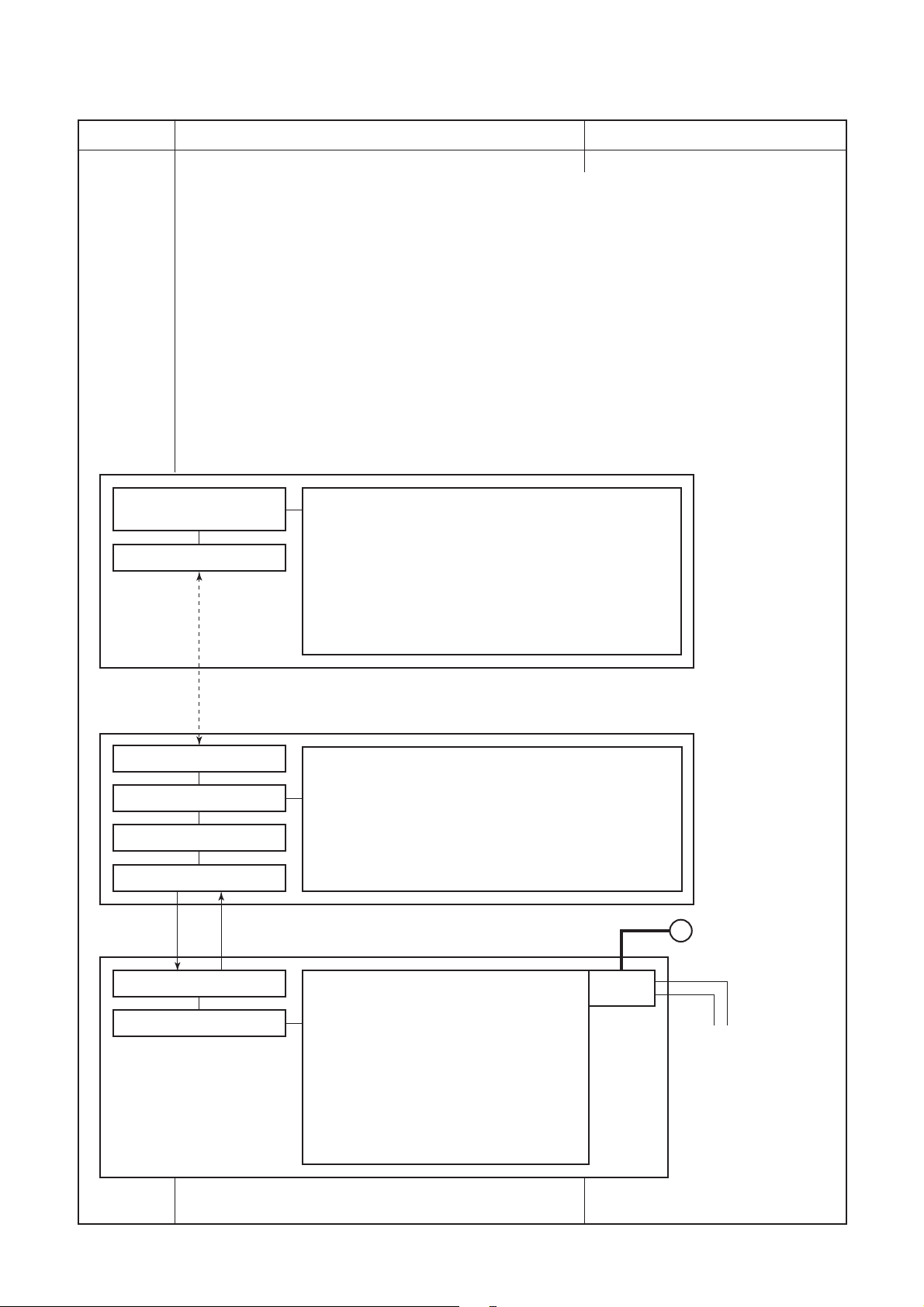
9-2. Operation Description
Item
1. Basic
operation
Operation flow and applicable data, etc. Description
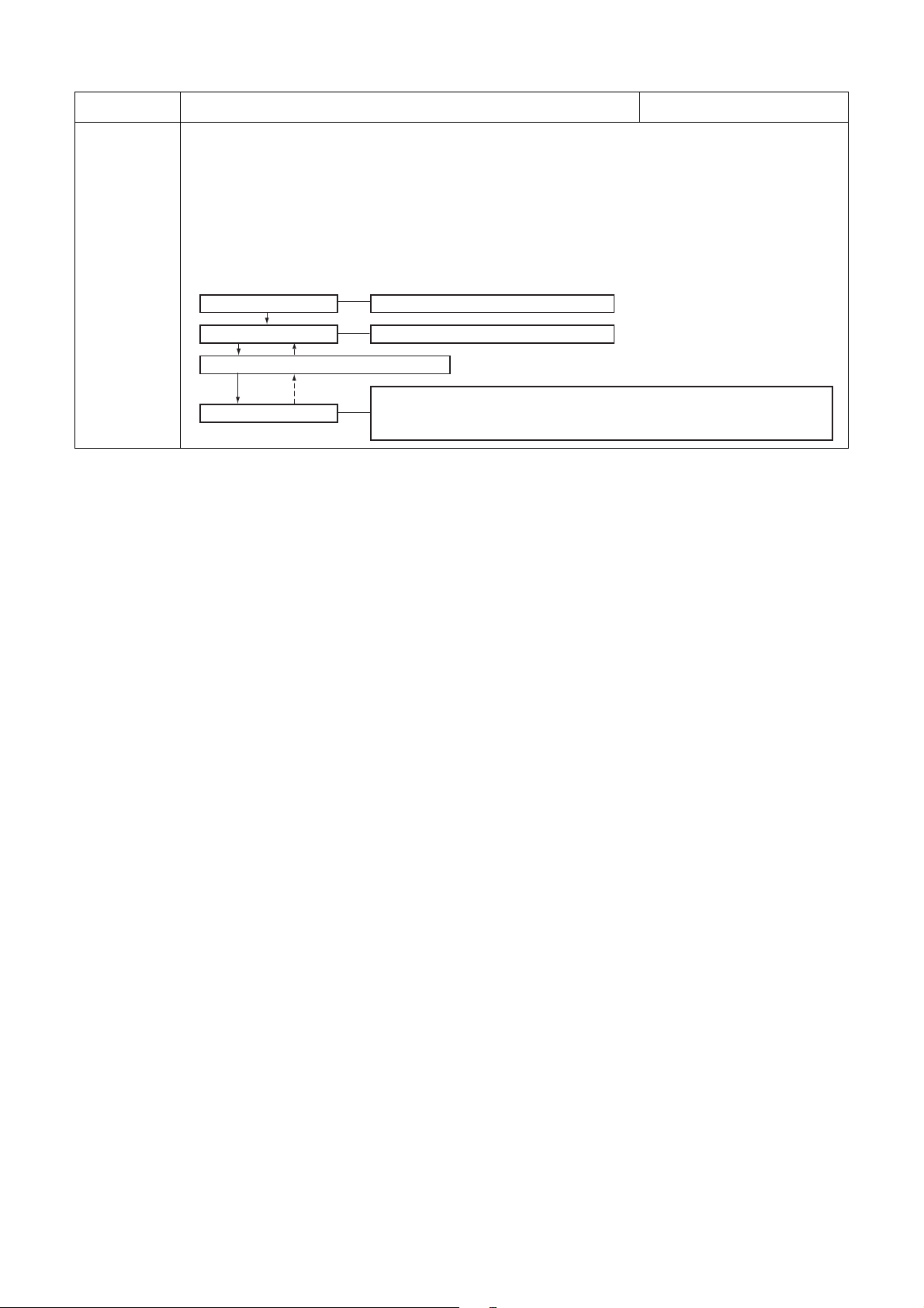
1-1. Operation control
Receiving the user’s operation condition setup, the operation statuses of indoor/outdoor units are
controlled.
1) The operation conditions are selected by the remote controller as shown in the below.
2) A signal is sent by ON button of the remote controller.
3) The signal is received by a sensor of the indoor unit and processed by the indoor controllers as
shown in the below.
4) The indoor controller controls the indoor fan motor and louver motor.
5) The indoor controller sends the operation command to the outdoor controller, and sends/receives
the control status with a serial signal.
6) The outdoor controller controls the operation as shown in the left, and also controls the
compressor, outdoor fan motor, 4-way valve and pulse motor valve.
Selection of
operation conditions
ON/OFF
Remote controller
Control contents of remote controller
•ON/OFF
• Operation select
• Temperature setup
• Air volume select (AUTO/LOW/LOW+/MED/MED+/HIGH)
•ECO
•ON timer setup
• OFF timer setup
•Hi-POWER
• COMFORT SLEEP
•QUIET
• PRESET
• ONE-TOUCH
Signal receiving
Indoor unit control
Operation command
Serial signal send/receive
Serial signal send/receive
Outdoor unit control
Indoor unit
Indoor unit control
• Command signal generating function of indoor unit
operation
• Calculation function (temperature calculation)
• Activation compensation function of indoor fan
• Cold draft preventive function
• Timer function
• Indoor heat exchanger release control
Outdoor unit
Outdoor unit control
• Frequency control of inverter output
• Waveform composite function
• Calculation function (Temperature
calculation)
• AD conversion function
• Quick heating function
• Delay function of compressor reactivation
• Current release function
• GTr over-current preventive function
• Defrost operation function
Inverter
• Indoor fan motor
•drain pump
~
• Compressor
• Outdoor fan motor
• 4-way valve
• Pulse motorvalve
(P.M.V.)
– 21 –

Item Operation flow and applicable data, etc. Description
1. Basic
operation
1-2.When power supply is reset
1) Based on EEPROM data and DIPSW, setting of the indoor fan
speed and other setting are loaded. During this loading (approx
30 seconds), operation cannot be accepted.
Air speed (rpm)
1-3. Operating mode selection when performing 2-room operation
1) The outdoor unit operation mode conforms to the instructions of the indoor unit that was pressed
first.
2) When combined operation consisting of cooling (dry) and heating, fan and heating, or cleaning
operation and heating is performed, operation conforms to the instructions of the indoor unit that was
pressed first as shown in the following table.
3) The indoor fan stops for the indoor unit that was pressed last and which instructions are ignored.
4) When three or four indoor units are operated concurrently, the priority is also given to operating mode
of the indoor unit which was pressed first as same as the case when two indoor units are operated
concurrently.
No. Indoor unit Set operating mode Actual indoor unit operation Actual outdoor unit operation
Pressed first Cooling (dry) Cooling (dry)
1
Pressed last Cooling (dry) Cooling (dry)
Pressed first Heating Heating
2
Pressed last Heating Heating
Pressed first Fan only Fan only
3
Pressed last Fan only Fan only
Pressed first Fan only Fan only
4
Pressed last Cooling (dry) Cooling (dry)
Pressed first Cooling (dry) Cooling (dry)
5
Pressed last Fan only Fan only
Pressed first Cooling (dry) Cooling (dry)
6
Pressed last Heating Fan stopped
Pressed first Heating Heating
7
Pressed last Cooling (dry) Fan stopped
Pressed first Cleaning operation Cleaning operation
8
Pressed last Cleaning operation Cleaning operation
Pressed first Cleaning operation Cleaning operation
9
Pressed last Cooling (dry) Cooling (dry)
Pressed first Cooling (dry) Cooling (dry)
10
Pressed last Cleaning operation Cleaning operation
Pressed first Cleaning operation Cleaning operation
11
Pressed last Fan only Fan only
Pressed first Fan only Fan only
12
Pressed last Cleaning operation Cleaning operation
Pressed first Cleaning operation Cleaning operation
13
Pressed last Heating Fan stopped
Pressed first Heating Heating
14
Pressed last Cleaning operation Fan stopped
Cooling
Heating
Stopped
Cooling
Cooling
Cooling
Heating
Stopped
Cooling
Cooling
Stopped
Stopped
Stopped
Heating
– 22 –
Item Operation flow and applicable data, etc. Description
1. Basic
operation
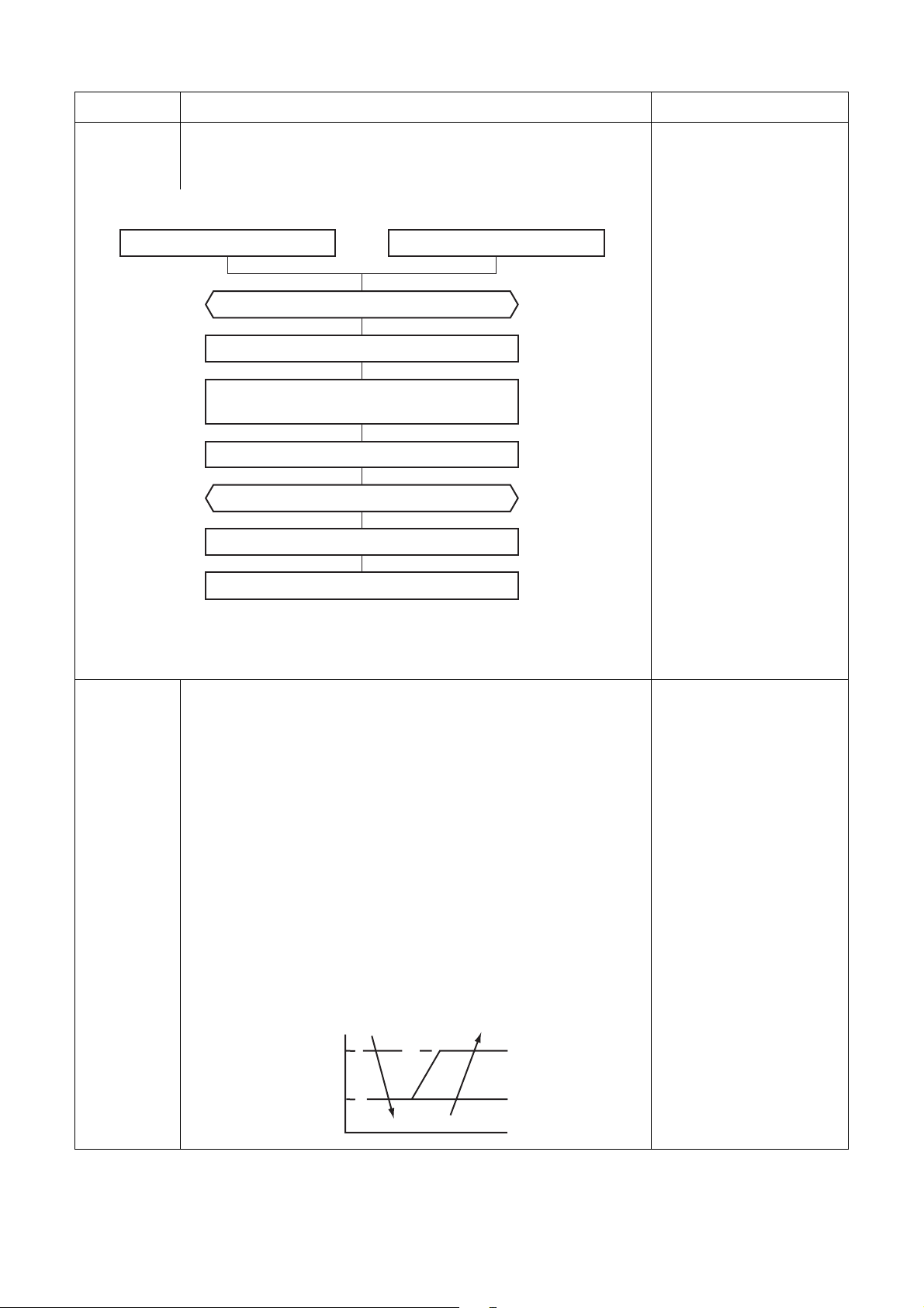
1-4. Cooling/Heating operation
The operations are performed in the following parts by controls according to cooling/heating conditions.
1) Receiving the operation ON signal of the remote controller, the cooling or heating operation signal
starts being transferred from the indoor controller to the outdoor unit.
2) At the indoor unit side, the indoor fan is operated according to the contents of “2. Indoor fan motor
control” and the drain pump according to the “5. Drain pump control”.
3) The outdoor unit controls the outdoor fan motor, compressor, pulse motor valve and 4-way valve
according to the operation signal sent from the indoor unit.
Operation On
Indoor unit control
Sending of operation command signal
Outdoor unit control
Setup of remote controller
Indoor fan motor control / drain pump
Compressor revolution control / Outdoor fan motor control / 4-way valve control
Pulse motor valve control
– 23 –

Item Operation flow and applicable data, etc. Description
1. Basic
operation
1-5. AUTO operation
Remote controller
command
• COOL/HEAT operation mode is
automatically selected by Ta, Ts
and To for operation.
• The operation is performed as
AUTO
+1.0
Ta
Ts +
(°C)
• α is corrected according to the outside temperature.
α
-1.0
shown in the following figure
according to Ta value at the first
time only. (In the range of Ts + α
–1 < Ta < Ts + α + 1, Cooling
thermo. OFF (Fan)/Setup air
volume operation continues.)
Cooling thermo. OFF (Fan only)
•
Setup air volume
Control outline
Cooling
operation
Heating
operation
Ta: Room temp.
Ts: Setup temp.
To: Outside temp.
Outside temp.
No To 0K
To ≥ 24°C –1K
24 > To ≥ 18°C 0K
To < 18°C +1K
To error 0K
Correction value (
α)
1) The judgment of selecting COOL/HEAT is carried out as shown
below. When +1.5 exceeds against Tsh 10 minutes and after
thermo. -OFF, heating operation (Thermo. OFF) exchanges to
cooling operation. Description in the parentheses shows an example
of cooling ON/OFF.
or
Ta
(°C)
+1.5
Tsc
Tsh
-1.5
Cooling OFF
Cooling
(Cooling ON)
Heating
When –1.5 lowers against Tsc 10 minutes and after thermo. OFF,
cooling operation (Thermo. OFF) exchanges to heating operation.
2) For the automatic capacity control after judgment of cooling/heating,
see Item 4.
3) For temperature correction of room temp. control in automatic
heating, see Item 3.
k = deg
Tsc: Setup temp. in cooling
operation
Tsh: Setup temp. in heating
operation + temp.
correction of room
temp. control
1-6. DRY operation
DRY operation is aimed to dehumidification.
In order to prevent lowering of the room temperature,
• Indoor fan speed is fixed to cooling L tap.
• Cooling capacity is restricted to low. When the room temperature is
lower than the setup temperature, the compressor is turned off.
– 24 –

Item Operation flow and applicable data, etc. Description
2. Indoor fan
motor
control
1) Operation with (HH), (H+), (H), (L+), (L) or [AUTO] mode is carried
out by the command from the remote controller.
2) When the air speed mode [AUTO] is selected, the air speed varies
by the difference between Ta and Ts.
<COOL>
Ta (˚C)
+3.0
+2.5
+2.0
+1.5
+1.0
+0.5
Tsc
–0.5
HH
(HH)
H+ (HH)
H (HH)
L+ (H+)
L (H)
L (H)
L (L+)
A
B
C
D
E
F
G
• Controlling operation in case when thermo of remote controller works
is same as a case when thermo of the body works.
• If the air speed has been changed once, it is not changed for
3 minutes. However when the air volume is exchanged, the air speed
changes.
• When cooling operation has started, select a downward slope for the
air speed, that is, the high position.
• If the temperature is just on the difference boundary, the air speed
does not change.
• Mode in the parentheses indicates one in automatic cooling
operation.
HH > H+ > H > L+ > L > UL
<HEAT>
Ta (˚C)
(–0.5) –1.0
Tsh
(+0.5) +1.0
(+1.0) +2.0
(+1.5) +3.0
(+2.0) +4.0
L (L+)
L+ (H)
H (H+)
H+
(HH)
HH
(HH)
E
D
C
B
A
Value in the parentheses indicates one when thermostat of the remote
controller works.
Value without parentheses indicates one when thermostat of the body
works.
• If the air speed has been changed once, it is not changed for 1
minute. However when the air speed is exchanged, the air speed
changes.
• When heating operation has started, select an upward slope for the
air speed, that is, the high position.
• If the temperature is just on the difference boundary, the air speed
does not change.
• Mode in the parentheses indicates one in automatic heating
operation.
•In Tc ≥ 60°C, the air speed increases by 1 step.
Tc: Indoor heat
exchanger sensor
temperature
– 25 –

Item Operation flow and applicable data, etc. Description
2. Indoor fan
motor
control
Revolution speed of indoor fan (rpm)
M07G3DV, M10G3DV
tap COOL HEAT
F1 HH 1020 1120 1200 1260
F2 HH 1020 1120 1200 1260
F3 H+ 960 1020 1120 1160
F4 H+ 960 1020 1120 1160
F5 H 880 940 1020 1040
F6 H 880 940 1020 1040
F7 L+ 820 870 940 980
F8 L+ 820 870 940 980
F9 L 740 780 850 890
FA L 740 780 850 890
FB 730 730 770 820
FC 730 730 770 820
FD LL LL 610 610 610 610
M13G3DV
tap COOL HEAT
F1 HH 1120 1160 1240 1300
F2 HH 1120 1160 1240 1300
F3 H+ 1000 1040 1140 1200
F4 H+ 1000 1040 1140 1200
F5 H 920 970 1040 1120
F6 H 920 970 1040 1120
F7 L+ 830 870 930 980
F8 L+ 830 870 930 980
F9 L 740 780 840 870
FA L 740 780 840 870
FB 730 730 770 820
FC 730 730 770 820
FD LL LL 610 610 610 610
External static pressure selection
10Pa 20Pa 35Pa 45Pa
External static pressure selection
10Pa 20Pa 35Pa 45Pa
M16G3DV
tap COOL HEAT
F1 HH 1020 1120 1220 1260
F2 HH 1020 1120 1220 1260
F3 H+ 960 970 1100 1140
F4 H+ 960 970 1100 1140
F5 H 810 810 960 1020
F6 H 810 810 960 1020
F7 L+ 730 750 810 960
F8 L+ 720 750 810 960
F9 L 660 700 760 800
FA L 630 670 720 760
FB 630 630 660 680
FC 630 630 640 660
FD LL LL 550 550 550 550
External static pressure selection
10Pa 20Pa 35Pa 45Pa
3) In heating operation, the mode changes to [LL] if thermostat is
turned off.
4) If Ta ≥ 25°C when heating operation has started and when defrost
operation has been cleared, the air conditioner operates with (H)
mode or higher mode for 1 minute after Tc entered in E zone of cool
air discharge preventive control.
Tcj:
Indoor heat exchanger
sensor temperature
– 26 –

Item Operation flow and applicable data, etc. Description
2. Indoor fan
motor
control
5) Self-clean operation
When performing self-clean operation after stopping the cooling
operation, the mode becomes LL (M07, M10, M13), L (M16).
Cool air discharge preventive control
1) In heating operation, the indoor fan is controlled based on the
detected temperature of Tc sensor or Tcj sensor. As shown below,
the upper limit of the revolution frequency is restricted.
However B zone is assumed as C zone for 6 minutes and after when
the compressor activated. In defrost operation, the control value of
Tc is shifted by 6°C.
Tc
(˚C)
Tcj
32
30
28
26
20
16
HH
H
L
UL
OFF
E zone
D zone
C zone
B zone
A zone
[Self-clean ] is displayed.
In D and E zones, the
priority is given to air volume
selection setup of remote
controller.
In A zone while thermo is
ON, [PRE-HEAT (Heating
ready)] is displayed.
– 27 –
Item Operation flow and applicable data, etc. Description
3. Capacity
control
The cooling or heating capacity depending on the load is adjusted.
According to difference between the setup value of temperature and the
room temperature, the capacity is adjusted by the compressor revolution.
Remote controller
Set temp. (Ts)
Ts –Ta
Correction of Hz signal
Detection of electromotive force
of compressor motor winding
Detection of motor speed and rotor position
Correction value of Hz signal Operating Hz
Inverter output change
Change of compressor speed
Indoor unit
Room temp. (Ta)
1) The difference between set
temperature on remote
controller (Ts) and room
temperature (Ta) is
calculated.
2) According to the
temperature difference, the
correction value of Hz
signal which determines
the compressor speed is
set up.
3) The rotating position and
speed of the motor are
detected by the
electromotive force
occurred on the motor
winding with operation of
the compressor.
4) According to the difference
resulted from comparison
of the correction value of
Hz signal with the present
operation Hz, the inverter
output is varied.
5) Change the compressor
motor speed by outputting
power to the compressor.
* The contents of control
operation are same in
cooling operation and
heating operation
4. Release
protective
control by
temperature
of indoor
heat
exchanger
Freeze preventive control (Low temperature release)
1) The cooling operation (including Dry operation) is performed as
follows based on the detected temperature of Tc sensor or Tcj
sensor.
When [J] zone is detected for 6 minutes (Following figure), the
commanded frequency is decreased from the real operation
frequency.
After then the commanded frequency changes every 30 seconds
while operation is performed in [J] zone.
In [K] zone, time counting is interrupted and the operation is held.
When [ I ] zone is detected, the timer is cleared and the operation
returns to the normal operation.
If the commanded frequency becomes S0 because the operation
continues in [J] zone, the return temperature A is raised from 7°C to
12°C until [ I ] zone is detected and the indoor fan operates with [L]
mode.
(˚C)
7
I
A
K
5
J
Tcj:
Indoor heat exchanger
sensor temperature
– 28 –
 Loading...