

Page 1

R32
ENGLISH
INSTALLATION MANUAL
AIR CONDITIONER (MULTIPLE TYPE)
Indoor unit
RAS-M10PKVPG-E
RAS-M13PKVPG-E
RAS-M16PKVPG-E
ESPAÑOL
FRANÇAIS
ITALIANO
DEUTSCH
PORTUGUÊS
POLSKI
ČESKY
HRVATSKI
MAGYAR
NEDERLANDS
ΕΛΛΗΝΙΚΑ
SVENSKA
SUOMI
NORSK
DANSK
ROMÂNĂ
БЪЛГАРСКИ
EESTI
LATVISKI
SLOVENČINA
SLOVENŠČINA
LIETUVIŲ
PУCСКИЙ
1121451199
Page 2

EN
CONTENTS
PRECAUTIONS FOR SAFETY ........................................................................................................................................... 1
ACCESSORY PARTS .........................................................................................................................................................5
INSTALLATION DIAGRAM OF INDOOR UNIT ..................................................................................................................6
Optional Installation Parts ...............................................................................................................................................6
INDOOR UNIT .....................................................................................................................................................................7
Installation Place ............................................................................................................................................................. 7
Cutting a Hole and Mounting Installation Plate ...............................................................................................................7
Piping and Drain Hose Installation ..................................................................................................................................8
Indoor Unit Fixing ............................................................................................................................................................9
In case of Indoor unit is fi xed to Installation plate with screws ........................................................................................9
Drainage .........................................................................................................................................................................9
ELECTRICAL WORKS .....................................................................................................................................................10
Wiring Connection .........................................................................................................................................................10
Connecting Cable Connection ....................................................................................................................................... 11
OTHERS ............................................................................................................................................................................ 12
Gas Leak Test ...............................................................................................................................................................12
Remote Control A-B Selection ......................................................................................................................................12
Test Operation ..............................................................................................................................................................12
Auto Restart Setting .....................................................................................................................................................12
Page 3
PRECAUTIONS FOR SAFETY
PRECAUTIONS FOR SAFETY
Read the precautions in
this manual carefully before
operating the unit.
• Before installation, please read these precautions for safety carefully.
• Be sure to follow the precautions provided here to avoid safety risks. The
symbols and their meanings are shown below.
WARNING : It indicates that incorrect use of this unit may cause severe injury or
death.
CAUTION : It indicates that incorrect use of this unit may cause personal injury
(*1), or property damage (*2).
*1: Personal injury means a slight accident, burn, or electrical shock
which does not require admission or repeated hospital treatment.
*2: Property damage means greater damage which affects assets or
resources.
For general public use
Power supply cord and connecting cable of appliance use shall be at least
polychloroprene sheathed fl exible cord (design H07RN-F) or cord designation
60245 IEC66. (Shall be installed in accordance with national wiring regulations.)
This appliance is fi lled with
R32.
EN
CAUTION
This appliance must be connected to the main power supply by means of a circuit
breaker or a switch with a contact separation of at least 3 mm in all poles.
To disconnect the appliance from the main power supply
1
Page 4

DANGER
• FOR USE BY QUALIFIED PERSONS ONLY.
• TURN OFF MAIN POWER SUPPLY BEFORE ATTEMPTING ANY ELECTRICAL
WORK. MAKE SURE ALL POWER SWITCHES ARE OFF.
FAILURE TO DO SO MAY CAUSE ELECTRIC SHOCK.
• CONNECT THE CONNECTING CABLE CORRECTLY. IF THE CONNECTING
CABLE IS CONNECTED WRONGLY, ELECTRIC PARTS MAY BE DAMAGED.
• CHECK THE EARTH WIRE THAT IT IS NOT BROKEN OR DISCONNECTED
BEFORE INSTALLATION.
• DO NOT INSTALL NEAR CONCENTRATIONS OF COMBUSTIBLE GAS OR
GAS VAPORS.
FAILURE TO FOLLOW THIS INSTRUCTION CAN RESULT IN FIRE OR
EXPLOSION.
• TO PREVENT OVERHEATING THE INDOOR UNIT AND CAUSING A FIRE
HAZARD, PLACE THE UNIT WELL AWAY (MORE THAN 2 M) FROM HEAT
SOURCES SUCH AS RADIATORS, HEATERS, FURNACE, STOVES, ETC.
• WHEN MOVING THE AIR CONDITIONER FOR INSTALLING IT IN ANOTHER
PLACE AGAIN, BE VERY CAREFUL NOT TO GET THE SPECIFIED
REFRIGERANT (R32) WITH ANY OTHER GASEOUS BODY INTO THE
REFRIGERATION CYCLE. IF AIR OR ANY OTHER GAS IS MIXED IN THE
REFRIGERANT, THE GAS PRESSURE IN THE REFRIGERATION CYCLE
BECOMES ABNORMALLY HIGH AND IT RESULTINGLY CAUSES BURST OF
THE PIPE AND INJURIES ON PERSONS.
• IN THE EVENT THAT THE REFRIGERANT GAS LEAKS OUT OF THE PIPE
DURING THE INSTALLATION WORK, IMMEDIATELY LET FRESH AIR
INTO THE ROOM. IF THE REFRIGERANT GAS IS HEATED BY FIRE OR
SOMETHING ELSE, IT CAUSES GENERATION OF POISONOUS GAS.
WARNING
• Never modify this unit by removing any of the safety guards or bypassing any of
the safety interlock switches.
• Do not install in a place which cannot bear the weight of the unit.
Personal injury and property damage can result if the unit falls.
• Before doing the electrical work, attach an approved plug to the power supply
cord.
Also, make sure the equipment is properly earthed.
• Appliance shall be installed in accordance with national wiring regulations.
If you detect any damage, do not install the unit. Contact your dealer
immediately.
2
Page 5

• Do not use any refrigerant different from the one specifi ed for complement or
replacement.
Otherwise, abnormally high pressure may be generated in the refrigeration
cycle, which may result in a failure or explosion of the product or an injury to
your body.
• Do not use means to accelerate the defrosting process or to clean, other than
those recommended by the manufacturer.
• The appliance shall be stored in a room without continuously operating ignition
sources (for example: open fl ames, an operating gas appliance or an operating
electric heater).
• Be aware that refrigerants may not contain an odour.
• Do not pierce or burn as the appliance is pressurized. Do not expose the
appliance to heat, fl ame, sparks, or other sources or ignition. Else, it may
explode and cause injury or death.
• For R32 model, use pipes, fl are nut and tools which is specifi ed for R32
refrigerant. Using of existing (R22) piping, fl are nut and tools may cause
abnormally high pressure in the refrigerant cycle (piping), and possibly result in
explosion and injury.
• Thickness of copper pipes used R32 must be more than 0.8mm. Never use
copper pipes thinner than 0.8mm.
• Do not perform fl are connection inside a building or dwelling or room, when
joining the heat exchanger of indoor unit with interconnection piping. Refrigerant
connection inside a building or dwelling or room must be made by brazing or
welding. Joint connection of indoor unit by fl aring method can only be made
at outdoor or at outside of building or dwelling or room. Flare connection may
cause gas leak and fl ammable atmosphere.
• After completion of installation or service, confi rm there is no leakage of
refrigerant gas. It may generate toxic gas when the refrigerant contacts with fi re.
• Appliance and pipe-work shall be installed, operated and stored in a room with a
fl oor area larger than A
How to get A
m2 : A
min
m2.
min
= (M / (2.5 x 0.22759 x h0))
min
2
M is the refrigerant charge amount in appliance in kg. h0 is the installation height
of the appliance in m: 0.6 m for fl oor standing/1.8 m for wall mounted/1.0 m for
window mounted/2.2 m for ceiling mounted (For these units recommend
installation height 2.5 m.).
• Comply with national gas regulations.
EN
3
Page 6

CAUTION
• Exposure of unit to water or other moisture before installation could result in
electric shock.
Do not store it in a wet basement or expose to rain or water.
• After unpacking the unit, examine it carefully for possible damage.
• Do not install the unit at place where leakage of fl ammable gas may occur. In
case gas leaks and accumulates at surrounding of the unit, it may cause of fi re.
• Do not install in a place that can increase the vibration of the unit. Do not
install in a place that can amplify the noise level of the unit or where noise and
discharged air might disturb neighbors.
• To avoid personal injury, be careful when handling parts with sharp edges.
• Please read this installation manual carefully before installing the unit. It contains
further important instructions for proper installation.
• The manufacturer shall not assume any liability for the damage caused by not
observing the description of this manual.
REQUIREMENT OF REPORT TO THE LOCAL POWER SUPPLIER
Please make absolutely sure that the installation of this appliance is reported to
the local power supplier before installation. If you experience any problems or if the
installation is not accepted by the supplier, the service agency will take adequate
countermeasures.
■
Important information regarding the refrigerant used
This product contains fl uorinated greenhouse gases.
Do not vent gases into the atmosphere.
Refrigerant type: R32
(1)
GWP
(1)
value: 675 * (ex. R32 ref. AR4)
GWP = global warming potential
The refrigerant quantity is indicated on the unit name plate.
* This value is based on F gas regulation 517/2014
4
Page 7
ACCESSORY PARTS
ACCESSORY PARTS
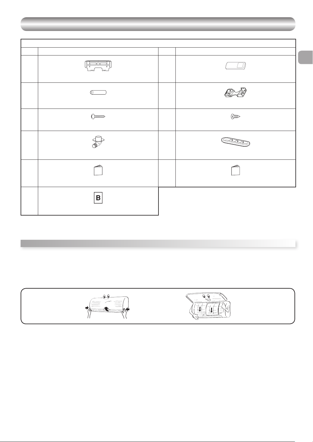
ACCESSORY AND INSTALLATION PARTS
No. Part name No. Part name
EN
1
Installation Plate* × 1
3
5
7
9
"
* The part may differ from that shown.
** The number of parts may differ by model.
*** The part is packed with the outdoor unit.
Air fi lters
Clean every 2 weeks.
1. Open the air inlet grille.
2. Remove the air fi lters.
3. Vacuum or wash and then dry them.
4. Reinstall the air fi lters and close the air inlet grille.
Mounting screw** Ø4 × 25R × 6
Drain nipple*** × 1 (for heating model only)
Battery × 2
Owner’s Manual
B Label × 2 (for Multi model)
2
4
6
8
!
Filter Clean / Replacement
Wireless remote control* × 1
Remote control holder* × 1
Flat head wood screw Ø3.1 × 16R × 2
Cap water proof**,*** × 2 (for some models only)
Installation Manual
5
Page 8
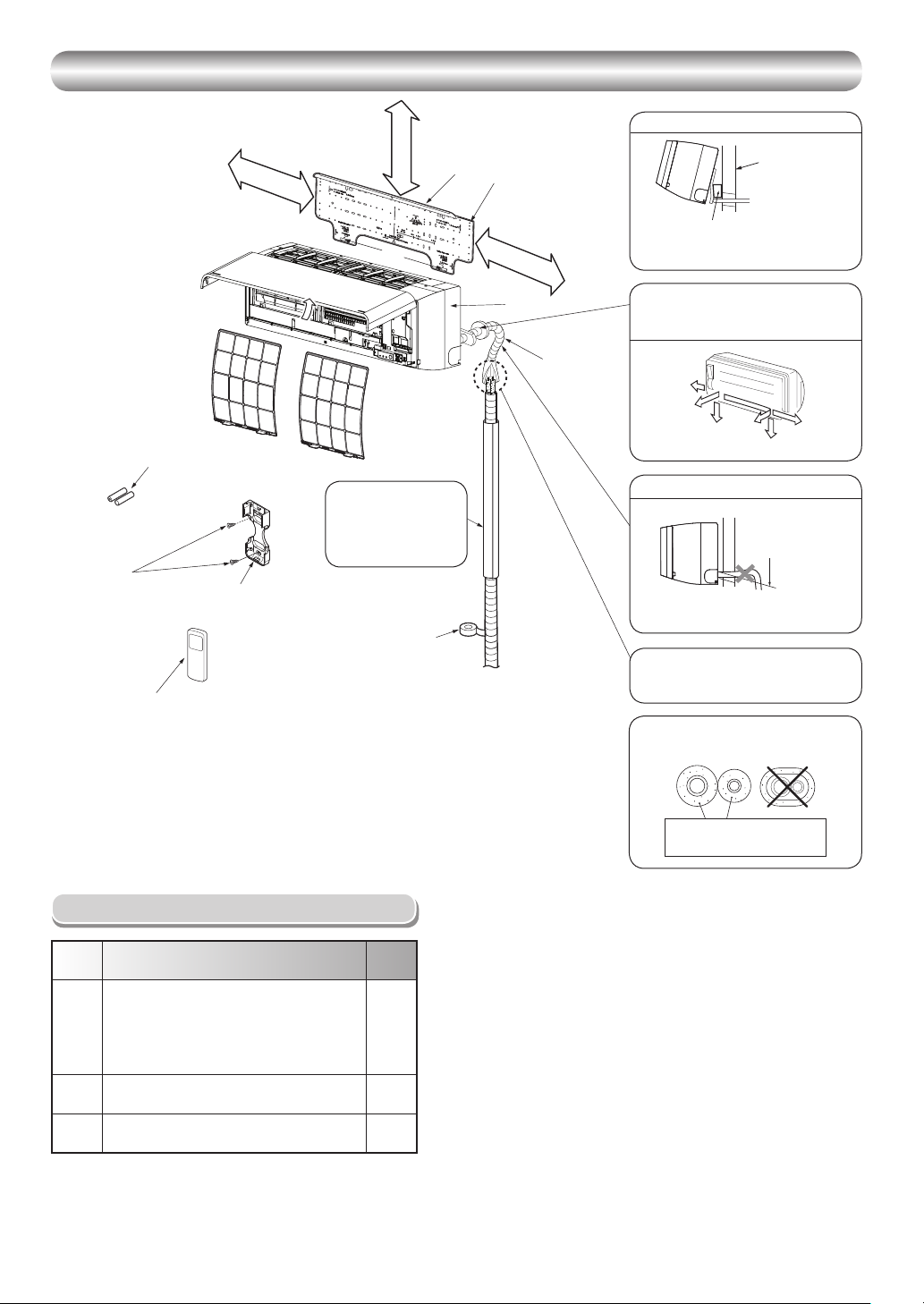
INSTALLATION DIAGRAM OF INDOOR UNIT
INSTALLATION DIAGRAM OF INDOOR UNIT
For the rear left and left piping
6
Flat head
wood screw
Batteries
3
Wireless remote control
2
190 mm or more
Air fi lter
(Attach to the front panel.)
Remote control
4
holder
Hook
52 mm or more
Hook
Refrigerant piping
must be protected from
physical damage.
Install a plastic cover or
equivalent.
Vinyl tape
Apply after carrying
out a drainage test.
Installation
1
plate
225 mm or more
Bush body
Shield pipe
Wall
Insert the cushion between the indoor
unit and wall, and tilt the indoor unit for
better operation.
The auxiliary piping can be connected to
the left, rear left, rear right, right, bottom
right or bottom left.
Right
Rear
right
Bottom
right
Rear
left
Left
Bottom left
Do not allow the drain hose to get slack.
Cut the piping
hole sloped
slightly.
Make sure to run the drain hose sloped
downward.
The fl are connection should be installed
outdoors.
Optional Installation Parts
Part
code
Refrigerant piping
Liquid side : Ø6.35 mm
Gas side : Ø9.52 mm
A
(RAS-M10, 13PKVPG-E)
: Ø12.7 mm
(RAS-M16PKVPG-E)
Pipe insulating material
B
(polyethylene foam, 6 mm thick)
Putty, PVC tapes
C
Parts name Q’ty
One
each
1
One
each
Insulate the refrigerant pipes separately
with insulation, not together.
6 mm thick heat resisting
polyethylene foam
6
Page 9

INDOOR UNIT
INDOOR UNIT
Installation Place
• A place which provides the spaces around the indoor unit as shown in the
diagram
• A place where there are no obstacles near the air inlet and outlet
• A place which allows easy installation of the piping to the outdoor unit
• A place which allows the front panel to be opened
• The indoor unit shall be installed at least 2.5 m height. Also, it must be
avoided to put anything on the top of the indoor unit.
CAUTION
• Direct sunlight to the indoor unit’s wireless receiver should be avoided.
• The microprocessor in the indoor unit should not be too close to RF
noise sources.
(For details, see the owner’s manual.)
Remote control
• A place where there are no obstacles such as a curtain that may block the
signal from the indoor unit
• Do not install the remote control in a place exposed to direct sunlight or close
to a heating source such as a stove.
• Keep the remote control at least 1 m apart from the nearest TV set or stereo
equipment. (This is necessary to prevent image disturbances or noise
interference.)
• The location of the remote control should be determined as shown below.
(Side view) (Top view)
Indoor unit
75º
Reception
range
Remote
control
Indoor unit
Reception range
45º
45º
Remote
control
Cutting a Hole and Mounting
Installation Plate
Cutting a hole
When installing the refrigerant pipes from the rear
35
65
Ø
The center of the pipe
hole is above the arrow.
1. After determining the pipe hole position on the mounting plate (Æ), drill the
pipe hole (Ø65 mm) at a slight downward slant to the outdoor side.
Mounting the installation plate
Anchor bolt holes
Hook
190
104
Weight
Hook
Pipe hole
5
Mounting screw
Pipe hole
Indoor unit
Hook
Thread
When the installation plate is directly mounted
on the wall
1. Securely fi t the installation plate onto the wall by screwing it in the upper and
lower parts to hook up the indoor unit.
2. To mount the installation plate on a concrete wall with anchor bolts, use the
anchor bolt holes as illustrated in the below fi gure.
3. Install the installation plate horizontally in the wall.
CAUTION
When installing the installation plate with a mounting screw, do not use the
anchor bolt holes. Otherwise, the unit may fall down and result in personal
injury and property damage.
Installation plate
(Keep horizontal direction.)
5 mm dia. hole
Mounting screw
5
Ø4 x 25R
Clip anchor
(local parts)
CAUTION
Failure to fi rmly install the unit may result in personal injury and property
damage if the unit falls.
• In case of block, brick, concrete or similar type walls, make 5 mm dia. holes
in the wall.
• Insert clip anchors for appropriate mounting screws 5.
40
137
Installation
plate
Anchor bolt
Projection
15 mm or less
52
225
1
NOTE
• Secure four corners and lower parts of the installation plate with 4 to 6
mounting screws to install it.
EN
NOTE
• When drilling a wall that contains a metal lath, wire lath or metal plate, be sure
to use a pipe hole brim ring sold separately.
7
Page 10
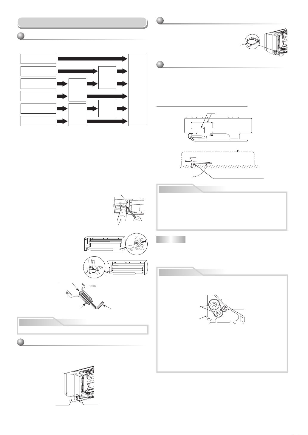
Piping and Drain Hose Installation
Piping and drain hose forming
* Since dewing results in a machine trouble, make sure to insulate both
connecting pipes. (Use polyethylene foam as insulating material.)
Rear right
Rear left
Bottom left
Bottom right
Left
Right
1. Die-cutting bush body slit
• For Bottom left or Bottom right
Cut out the slit on bottom left or right side of bush body for the bottom left
or right connection with a pair of nippers.
• For Left or Right
Take off Cap and cut out the slit on left or right side of bush body for the
left or right connection with a pair of nippers.
2. Changing drain hose
For leftward connection, bottom-leftward connection and rearleftward
connection’s piping, it is necessary to change the drain hose and drain
cap.
How to remove the drain hose
• The drain hose can be removed by removing the
screw securing the drain hose and then pulling out
the drain hose.
• When removing the drain hose, be careful of any
sharp edges of steel plate. The edges can injuries.
• To install the drain hose, insert the drain hose
fi rmly until the connection part contacts with heat
insulator, and then secure it with original screw.
How to remove the drain cap
Clip the drain cap by needle-nose
pliers and pull out.
How to fi x the drain cap
1) Insert hexagon wrench (4 mm)
in a center head.
slit
bush body
Die-cutting
body slit
Take off cap
and cut bush
2) Firmly insert the drain cap.
Do not apply lubricating oil
(refrigerant machine oil)
when inserting the drain
cap. Application causes
deterioration and drain
leakage of the plug.
No gap
CAUTION
Firmly insert the drain hose and drain cap; otherwise, water may leak.
In case of right or left piping
• Take off the cap by hand and cut of the slit.
• After scribing slits of the bush body with a knife or a making-off pin, cut
them with a pair of nippers or an equivalent tool.
Changing
drain hose
hose
drain
Changing
Heat insulator
Drain hose
Insert a hexagon wrench
(4 mm).
Piping preparation
In case of bottom right or bottom left piping
• After scribing slits of the bush body with a
knife or a making-off pin, cut them with a
pair of nippers or an equivalent tool.
Slit
Left-hand connection with piping
• Bend the connecting pipe so that it is laid within 43 mm above the wall
surface. If the connecting pipe is laid exceeding 43 mm above the wall
surface, the indoor unit may unstably be set on the wall.
When bending the connecting pipe, make sure to use a spring bender so as
not to crush the pipe.
Bend the connecting pipe within a radius of 30 mm.
To connect the pipe after installation of the unit (fi gure)
(To the forefront of fl are)
326 mm
283 mm
43 mm
Gas side
Liquid side
Outward form of indoor unit
R 30 mm (Use polisin (polyethylene)
core or the like for bending pipe.)
80°
Use the handle of screwdriver, etc.
WARNING
• Do not perform fl are connection inside a building or dwelling or room,
when joining the heat exchanger of indoor unit with interconnection
piping. Refrigerant connection inside a building or dwelling or room
must be made by brazing or welding. Joint connection of indoor
unit by fl aring method can only be made at outdoor or at outside of
building or dwelling or room. Flare connection may cause gas leak
and fl ammable atmosphere.
NOTE
If the pipe is bent incorrectly, the indoor unit may unstably be set on the wall.
After passing the connecting pipe through the pipe hole, connect the
connecting pipes to the auxiliary pipes and wrap the facing tape around
them.
CAUTION
• Bind the auxiliary pipes (two) and connecting cable with facing tape
tightly. In case of leftward piping and rear-leftward piping, bind the
auxiliary pipes (two) only with facing tape.
Indoor unit
Auxiliary pipes
Installation plate
• Carefully arrange pipes so that any pipe does not stick out of the rear
plate of the indoor unit.
• Carefully connect the auxiliary pipes and connecting pipes to one
another and cut off the insulating tape wound on the connecting pipe
to avoid double-taping at the joint; moreover, seal the joint with the
vinyl tape, etc.
• Since dewing results in a machine trouble, make sure to insulate both
connecting pipes. (Use polyethylene foam as insulating material.)
• When bending a pipe, carefully do it, not to crush it.
Connecting cable
Cap
Slit
8
Page 11
Indoor Unit Fixing
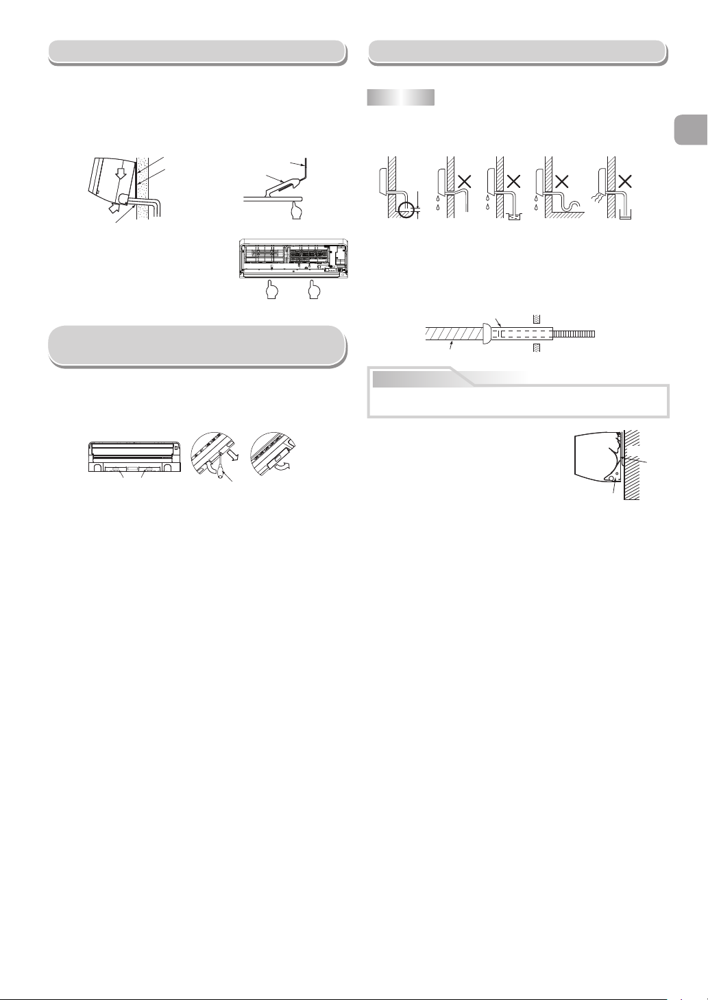
Drainage
1. Pass the pipe through the hole in the wall and hook the indoor unit on the
installation plate at the upper hook.
2. Swing the indoor unit to right and left to confi rm that it is fi rmly hooked up on
the installation plate.
3. While pressing the indoor unit onto the wall, hook it at the lower part on the
installation plate. Pull the indoor unit toward you to confi rm that it is fi rmly
hooked up on the installation plate.
Hook here.
Installation plate
1
2
Hook
• For detaching the indoor unit from the
installation plate, pull the indoor unit
toward you while pushing its bottom up
at the specifi ed parts.
1
Installation plate
Hook
Push
Push Push
In case of Indoor unit is fi xed to
Installation plate with screws
1. Remove 2 screw caps with fl at screwdriver.
2. Fix them with Ø4x10~14L, 2 screws which are prepared at the site.
3. Cover screw caps as previous process.
<How to remove> <How to fi x>
Screw cap
Flat screwdriver
1. Run the drain hose sloped downwards.
NOTE
• The hole should be made at a slight downward slant on the outdoor side.
Do not rise the
drain hose.
50 mm
or more
Do not put the
drain hose end
into water.
2. Put water in the drain pan and make sure that the water is drained out of
doors.
3. When connecting extension drain hose, insulate the connecting part of
extension drain hose with shield pipe.
Shield pipe
Drain hose
Inside the room
CAUTION
Arrange the drain pipe for proper drainage from the unit.
Improper drainage can result in dew-dropping.
This air conditioner has the structure designed
to drain water collected from dew, which forms
on the back of the indoor unit, to the drain pan.
Therefore, do not store the power cord and other
parts at a height above the drain guide.
Do not form the
drain hose into
a wavy shape.
Extension drain hose
Do not put the
drain hose end
in the drainage ditch.
Space for pipes
Wall
Drain
guide
EN
9
Page 12

ELECTRICAL WORKS
ELECTRICAL WORKS
Model RAS-M10PKVPG-E RAS-M13PKVPG-E RAS-M16PKVPG-E
Power source 50Hz, 220 – 240 V Single phase
Maximum running current *1 *1 *1
Circuit breaker rating *1 *1 *1
Power supply cable −
Connecting cable *1
*1: Refer to the installation manual of the outdoor unit to be combined.
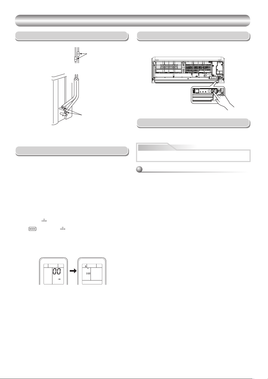
Wiring Connection
Indoor unit
Wiring of the cable can be carried out without removing the main panel.
1. Remove the front panel.
Pull and lift up front panel until it stops, move arms on left and right side
to outward direction then pull toward you to remove front panel.
w Beware front panel fall down that may cause of injure or part damage.
Guide
Arm
Arm
2. Remove the terminal cover and cord clamp.
3. Insert the cable (according to the local cords) into the pipe hole on the
wall.
4. Take out the cable protrudes about 20 cm from the front.
5. Insert the cable fully into the terminal block and secure it tightly with
screws.
6. Tightening torque : 1.2 N·m (0.12 kgf·m)
7. Secure the cable with the cord clamp.
8. Fix the terminal cover and attach front panel to the indoor unit.
Front panel
Cable
about 20 cm
Terminals block
Main panel
Terminal cover
How to attach the front panel
Arm
Main panel
Front panel
CAUTION
• Be sure to refer to the wiring system diagram labeled inside the main
panel.
• Check local electrical cords and also any specifi c wiring instructions or
limitations.
Carry out attaching in the reverse order to removal.
Keep front panel horizontally and put both arms into guides.
Make sure both arms are inserted completely.
If the gap between main panel and front panel isn’t even, remove and attach
again.
10
Page 13

Connecting Cable Connection
Connecting cable
CAUTION
Power supply must input at Outdoor Unit Terminal Block.
Wiring Diagram
Indoor
Terminal
Block
1
3
2
Connecting cable connect to
terminal block (1, 2, 3, ˙)
Stripping length of the connecting cable
Earth line
50 mm
10 mm
3
10 mm
45 mm
Connecting cable
about 20 cm
EN
Outdoor
Terminal
Block
1(L)
3
2
L
L
Power supply input
N
N
Chassis
GND
CAUTION
1. The power supply must be same as the rated of air conditioner.
2. Prepare the power source for exclusive use with air conditioner.
3. Circuit breaker must be used for the power supply line of this air conditioner.
4. Be sure to comply power supply and connecting cable for size and wiring method.
5. Every wire must be connected fi rmly.
6. Perform wiring works so as to allow a general wiring capacity.
7. Wrong wiring connection may cause some electrical part burn out.
8. Incorrect or incomplete wiring is carried out, it will cause an ignition or smoke.
11
Page 14
OTHERS
OTHERS
Gas Leak Test Test Operation
To switch to the TEST RUN (COOL) mode, press Temporary switch for
Check places for
the indoor unit.
Check places for
the outdoor unit.
10 seconds. (The unit will make a short Pi sound.)
Temporary switch
Auto Restart Setting
• Check the fl are nut connections for the gas leak with a gas leak detector or
soap water.
Remote Control A-B Selection
• When two indoor units are installed in the same room or adjacent two
rooms, if operating a unit, two units may receive the remote control signal
simultaneously and operate. In this case, the operation can be preserved
by setting either one remote control to B setting. (Both are set to A setting
in factory shipment.)
• The remote control signal is not received when the settings of indoor unit
and remote control are different.
• There is no relation between A setting/B setting and A room/B room when
connecting the piping and cables.
To separate using of remote control for each indoor unit in case of 2 air
conditioner are installed near.
Remote Control B Setup.
1. Press RESET button on the indoor unit to turn the air conditioner ON.
2. Point the remote control at the indoor unit.
3. Push and hold
“00” will be shown on the display.
4. Press
disappear and the air conditioner will turn OFF. The Remote Control B is
memorized.
Note : 1. Repeat above step to reset Remote Control to be A.
2. Remote Control A has not “A” display.
3. Default setting of Remote Control from factory is A.
button on the Remote Control by the tip of the pencil.
during pushing . “B” will show on the display and “00” will
This product is designed so that, after a power failure, it can restart
automatically in the same operating mode as before the power failure.
Information
The product was shipped with Auto Restart function in the off position.
Turn it on as required.
How to set the Auto Restart
1. Press and hold the Temporary switch on the indoor unit for 3 seconds to
set the operation (3 Pi sound and OPERATION lamp blink 5 time/sec for
5 seconds).
2. Press and hold the Temporary switch on the indoor unit for 3 seconds to
cancel the operation (3 Pi sound but OPERATION lamp does not blink).
• In case of ON timer or OFF timer are set, AUTO RESTART OPERATION
does not activate.
12
 Loading...