

Toshiba RAS-M10SKCV, RAS-M22NKCV1, RAS-M22SKCV, RAS-4M26SACV, RAS-M13SKCV SERVICE MANUAL
...
FILE NO.A07-007
Revised 1: Jul., 2008
SERVICE MANUAL
AIR-CONDITIONER
SPLIT TYPE
RAS-M10SKCV, RAS-M13SKCV,
RAS-M16SKCV, RAS-M22SKCV,
RAS-M22NKCV1
/ RAS-4M26SACV
R410A
PRINTED IN JAPAN, Jul., 2008 ToMo

CONTENTS
1. SAFETY PRECAUTIONS .......................................................................... 3
2. SPECIFICATIONS...................................................................................... 5
3. REFRIGERANT R410A ........................................................................... 13
4. CONSTRUCTION VIEWS ........................................................................ 21
5. WIRING DIAGRAM.................................................................................. 25
6. SPECIFICATIONS OF ELECTRICAL PARTS ......................................... 29
7. REFRIGERANT CYCLE DIAGRAM ........................................................ 30
8. CONTROL BLOCK DIAGRAM................................................................ 32
9. OPERATION DESCRIPTION ................................................................... 34
10. INSTALLATION PROCEDURE ................................................................ 60
11. HO W TO DIA GNOSE THE PROBLEM..................................................... 84
12. HO W TO REPLA CE THE MAIN P ARTS................................................. 112
13. EXPLODED VIEWS AND PARTS LIST ................................................. 134
1. SAFETY PRECAUTIONS
Power supply cord of outdoor unit shall be more than 2.5 mm² (H07RN-F or 60245IEC66) polychloroprene
sheathed flexible cord.
• Read this “SAFETY PRECAUTIONS” carefully before servicing.
• The precautions described below include the important items regarding safety. Observe them without fail.
• After the servicing work, perform a trial operation to check for any problem.
• Turn off the main power supply switch (or breaker) before the unit maintenance.
CAUTION
New Refrigerant Air Conditioner Installation
• THIS AIR CONDITIONER ADOPTS THE NEW HFC REFRIGERANT (R410A) WHICH DOES NOT
DESTROY OZONE LAYER.
R410A refrigerant is apt to be affected by impurities such as water, oxidizing membrane, and oils because
the working pressure of R410A refrigerant is approx. 1.6 times higher than that of refr igerant R22. Accompanied with the adoption of the new refrigerant, the refrigeration machine oil has also been changed.
Therefore, during installation work, be sure that water, dust, former refrigerant, or refrigeration machine oil
does not enter into the new type refrigerant R410A air conditioner circuit.
To prevent mixing of refrigerant or refrigerating machine oil, the sizes of connecting sections of charging
port on main unit and installation tools are different from those used for the conventional refrigerant units.
Accordingly, special tools are required for the new refrigerant (R410A) units.
For connecting pipes, use new and clean piping materials with high pressure fittings made for R410A only,
so that water and/or dust does not enter. Moreover, do not use the existing piping because there are some
problems with pressure fittings and possible impurities in existing piping.
CAUTION
TO DISCONNECT THE APPLIANCE FROM THE MAIN POWER SUPPLY
This appliance must be connected to the main power supply by a circuit breaker or a switch with a contact
separation of at least 3 mm.
DANGER
• ASK AN AUTHORIZED DEALER OR QUALIFIED INSTALLATION PROFESSIONAL TO INSTALL/MAINTAIN THE AIR CONDITIONER.
INAPPROPRIATE SERVICING MAY RESULT IN WATER LEAKAGE, ELECTRIC SHOCK OR FIRE.
• TURN OFF MAIN POWER SUPPLY BEFORE ATTEMPTING ANY ELECTRICAL WORK.
MAKE SURE ALL POWER SWITCHES ARE OFF. FAILURE TO DO SO MAY CAUSE ELECTRIC SHOCK.
DANGER: HIGH VOLTAGE
The high voltage circuit is incorporated.
Be careful to do the check service, as the electric shock may be caused in case of touching parts
on the P.C. board by hand.
• CORRECTLY CONNECT THE CONNECTING CABLE. IF THE CONNECTING CABLE IS
INCORRECTLY CONNECTED, ELECTRIC PARTS MAY BE DAMAGED.
• CHECK THAT THE EARTH WIRE IS NOT BROKEN OR DISCONNECTED BEFORE SERVICE AND
INSTALLATION. FAILURE TO DO SO MAY CAUSE ELECTRIC SHOCK.
• DO NOT INSTALL NEAR CONCENTRATIONS OF COMBUSTIBLE GAS OR GAS VAPORS.
FAILURE TO FOLLOW THIS INSTRUCTION CAN RESULT IN FIRE OR EXPLOSION.
– 3 –
• TO PREVENT THE INDOOR UNIT FROM OVERHEATING AND CAUSING A FIRE HAZARD, PLACE
THE UNIT WELL AWAY (MORE THAN 2 M) FROM HEAT SOURCES SUCH AS RADIATORS, HEAT
RESISTORS, FURNACE, STOVES, ETC.
• WHEN MOVING THE AIR-CONDITIONER FOR INSTALLATION IN ANOTHER PLACE, BE VERY
CAREFUL NOT TO ALLOW THE SPECIFIED REFRIGERANT (R410A) TO BECOME MIXED WITH ANY
OTHER GASEOUS BODY INTO THE REFRIGERATION CIRCUIT.
IF AIR OR ANY OTHER GAS IS MIXED IN THE REFRIGERANT, THE GAS PRESSURE IN THE
REFRIGERATION CIRCUIT WILL BECOME ABNORMALLY HIGH AND IT MAY RESULT IN THE PIPE
BURSTING AND POSSIBLE PERSONNEL INJURIES.
• IN THE EVENT THAT THE REFRIGERANT GAS LEAKS OUT OF THE PIPE DURING THE SERVICE
WORK AND THE INSTALLATION WORK, IMMEDIATELY LET FRESH AIR INTO THE ROOM.
IF THE REFRIGERANT GAS IS HEATED, SUCH AS BY FIRE, GENERATION OF POISONOUS GAS
MAY RESULT.
WARNING
• Never modify this unit by removing any of the safety guards or bypass any of the safety interlock
switches.
• Do not install in a place which cannot bear the weight of the unit. Personal injury and property
damage can result if the unit falls.
• After the installation work, confirm that refrigerant gas does not leak.
If refrigerant gas leaks into the room and flows near a fire source such as a cooking range, noxious gas
may generate.
• The electrical work must be perf ormed by a qualified electrician in accordance with the Installation
Manual. Make sure the air conditioner uses an exclusive circuit.
An insufficient circuit capacity or inappropriate installation may cause fire.
• When wiring, use the specified cables and connect the terminals securely to prevent external
forces applied to the cable from affecting the terminals.
• Be sure to provide grounding.
Do not connect ground wires to gas pipes, water pipes, lightning rods or ground wires for telephone cables.
Inappropriate grounding may cause electric shock.
• Conform to the regulations of the local electric company when wiring the power supply.
CAUTION
• Exposure of unit to water or other moisture before installation may result in an electrical short.
Do not store in a wet basement or expose to rain or water.
• Do not install in a place that can increase the vibration of the unit.
Do not install in a place that can amplify the noise level of the unit or where noise or discharged air might
disturb neighbors.
• To avoid personal injury, be careful when handling par ts with sharp edges.
• Perform the specified installation work to guard against an earthquake.
If the air conditioner is not installed appropriately, accidents may occur due to the falling unit.
For Reference:
If a heating operation would be continuously performed for a long time under the condition that the outdoor
temperature is 0°C or lower, drainage of defrosted water may be difficult due to freezing of the bottom plate,
resulting in a problem of the cabinet or fan.
It is recommended to procure an antifreeze heater locally for a safe installation of the air conditioner.
For details, contact the dealer.
– 4 –
2. SPECIFICATIONS
The indoor and outdoor units that can be used in combination are shown in the tables below.
Table of models that can be connected
Type
Cooling-only
Outdoor unit
RAS-4M26SACV
Indoor unit RAS-
M10SKCV M13SKCV M16SKCV M22NKCV1 M22SKCV
M10SDCV M13SDCV M16SDCV M22SDCV —
NOTES
1-room connection is not an option for the indoor units (you cannot connect only one indoor unit).
Be sure to connect indoor units in two rooms or more.
The contents noted in this service manual limit the indoor units to the RAS-M10SKCV, RAS-M13SKCV,
RAS-M16SKCV, RAS-M22SKCV and RAS-M22NKCV1.
For other indoor units that can also be used in combination, see the service manual of each indoor unit.
Indoor unit
RAS-M10SDCV
RAS-M13SDCV
RAS-M16SDCV
File No.
A07-002
RAS-M22SDCV
– 5 –
2-1. Specifications
<Cooling only Models>
RAS-M10SKCV, RAS-M13SKCV, RAS-M16SKCV, RAS-M22NKCV1 / RAS-4M26SACV
Unit model
Cooling capacity (kW)
Cooling capacity range (kW)
Heating capacity (kW)
Heating capacity range (kW)
Power supply
Electric
characteristics
COP (Cooling)
Operating
noise
Indoor unit Depth (mm)
Outdoor unit
Piping
connection
Wiring connection
Usable
temperature range
Accessory
Indoor
Outdoor
Unit model
Indoor
Total Power consumption (W)
Indoor
(Cooling/Heating)
Outdoor
Unit model
Dimension Width (mm)
Net weight (kg)
Fan motor output (W)
Air flow rate (Cooling/Heating) (m³/h)
Dimension Width (mm)
Net weight (kg)
Compressor Type
Fan motor output (W)
Air flow rate (m³/h)
Type
Indoor unit Liquid side
Outdoor unit
Maximum length (per unit) (m)
Minimum length (per unit) (m)
Maximum length (total) (m)
Maximum chargeless length
Additional refrigerant
Maximum height difference (m)
Name of refrigerant
Weight (kg)
Power supply
Interconnection
Indoor (Cooling/Heating) (°C)
Outdoor (Cooling/Heating) (°C)
Indoor unit
Outdoor unit
Running current (A)
Power consumption (W)
Power factor (%)
Operation mode
Running current (A)
Power factor (%)
Starting current (A)
Unit model
High dB (A)
Medium dB (A)
Low dB (A)
Cooling dB (A)
Heating dB (A)
Height (mm)
Height (mm)
Depth (mm)
Motor output (W)
Model
Unit model
Gas side
A unit liquid side/gas side
B unit liquid side/gas side
C unit liquid side/gas side
D unit liquid side/gas side
Installation plate
Wireless remote controller
Batteries
Remote controller holder
Pan head wood screw
Super Oxi Deo filter
Super Steriling filter
Zeolite plus sasa filter
Bio Gingo filter
Mounting screw
Owner’s manual
Installation manual
Owner’s manual
Installation manual
• For performance when each indoor unit is combined with other unit, refer to the separate table.
• The specifications may be subject to change without notice for purpose of improvement.
RAS-M10SKCV, RAS-M13SKCV, RAS-M16SKCV, RAS-M22NKCV1
RAS-4M26SACV
7.5
3.7 – 10.0
—
—
220–240 V, 1 Ph, 50Hz / 220 V, 1 Ph, 60Hz
RAS-M10SKCV RAS-M13SKCV RAS-M16SKCV RAS-M22NKCV1
0.21 / 0.20 / 0.19 0.21 / 0.20 / 0.19 0.21 / 0.20 / 0.19 0.31 / 0.30 / 0.29
35 35 30 45
75 75 65 45
Cooling
10.54 / 10.08 / 9.66
2200
95
10.54 / 10.08 / 9.66
3.41
RAS-M10SKCV RAS-M13SKCV RAS-M16SKCV RAS-M22NKCV1
38 / – 39 / – 45 / – 45 / –
33 / – 33 / – 40 / – 42 / –
26 / – 26 / – 30 / – 37 / –
48
—
RAS-M10SKCV RAS-M13SKCV RAS-M16SKCV RAS-M22NKCV1
275 275 275 298
790 790 790 998
205 205 205 220
99913
20 20 30 30
535 / – 565 / – 690 / – 850 / –
795
900
320
61
2000
Twin rotary type with DC-inverter variable speed control
DA220A1F-20L
60
High : 3200, Medium : 2800
Flare connection
RAS-M10SKCV RAS-M13SKCV RAS-M16SKCV RAS-M22NKCV1
Ø6.35 Ø6.35 Ø6.35 Ø6.35
Ø9.52 Ø9.52 Ø12.7 Ø12.7
Ø6.35 / Ø12.7
Ø6.35 / Ø9.52
Ø6.35 / Ø9.52
Ø6.35 / Ø9.52
25
2
70
70
No additional refrigerant
15
R410A
2.20
3 wires : includes earth
4 wires : includes earth
21 – 32 / –
10 – 46 / –
11
11
22
11
2 (Ø3.1 × 16L) 2 (Ø3.1 × 16L)
1 —
1 —
— 1
— 1
6 (Ø4 × 25L) 6 (Ø4 × 25L)
11
11
1
1
– 6 –
RAS-M22SKCV
Unit model
Cooling capacity (kW)
Cooling capacity range (kW)
Heating capacity (kW)
Heating capacity range (kW)
Power supply
Electric
characteristics
Operating noise Medium dB (A)
Indoor unit
Piping connection Indoor unit
Wiring connection Indoor unit Interconnection
Usable temperature range Indoor (°C)
Accessory Indoor unit
Indoor
Outdoor
Unit model
Indoor
Indoor
Sound presure level
Dimension Width (mm)
Net weight (kg)
Fan motor output (W)
Air flow rate (m³/h)
Type
Name of refrigerant
Running current (A)
Power consumption (W)
Power factor (%)
High dB (A)
Low dB (A)
Height (mm)
Depth (mm)
Liquid side
Gas side
Installation plate
Wireless remote controller
Batteries
Remote controller holder
Pan head wood screw
Super Oxi Deo filter
Super Steriling filter
Mounting screw
Owner’s manual
Installation manual
RAS-M22SKCV
RAS-4M26SACV
7.5
3.7 – 10.0
—
—
220–240 V, 1 Ph, 50Hz / 220 V, 1 Ph, 60Hz
RAS-M22SKCV
0.38 / 0.36 / 0.35
50
60
47
41
35
320
1050
228
13
30
1080
Flare connection
Ø6.35
Ø12.7
R410A
4 wires : includes earth
21 – 32
1
1
2
1
2 (Ø3.1 × 16L)
1
1
6 (Ø4 × 25L)
1
1
• For performance when each indoor unit is combined with other unit, refer to the separate table.
• The specifications may be subject to change without notice for purpose of improvement.
– 7 –
2-2. Specifications of Performance When Each Indoor Unit is Combined with Other Unit
<Current limited : Full operation / 220V>
Current
limited
Full
operation
Power
supply
(V)
220
Operating
status
1 unit
2 units
3 units
4 units
Indoor unit
ABCD
10 ———
13 ———
16 ———
22 ———
10 10 ——
13 10 ——
16 10 ——
13 13 ——
16 13 ——
16 16 ——
22 10 ——
22 13 ——
22 16 ——
22 22 ——
10 10 10 —
13 10 10 —
16 10 10 —
13 13 10 —
16 13 10 —
13 13 13 —
16 16 10 —
16 13 13 —
16 16 13 —
16 16 16 —
22 10 10 —
22 13 10 —
22 13 13 —
22 16 10 —
22 16 13 —
10 10 10 10
13 10 10 10
16 10 10 10
13 13 10 10
16 13 10 10
13 13 13 10
16 13 13 10
13 13 13 13
16 16 10 10
22 10 10 10
Operating
ABCD
2.70 ———
3.70 ———
4.50 ———
6.00 ———
2.70 2.70 ——
3.41 2.49 ——
3.94 2.36 ——
3.15 3.15 ——
3.73 3.07 ——
3.60 3.60 ——
4.97 2.23 ——
4.64 2.86 ——
4.29 3.21 ——
3.75 3.75 ——
2.50 2.50 2.50 —
3.04 2.23 2.23 —
3.40 2.05 2.05 —
2.75 2.75 2.00 —
3.10 2.55 1.85 —
2.50 2.50 2.50 —
2.88 2.88 1.74 —
2.84 2.33 2.33 —
2.66 2.66 2.18 —
2.50 2.50 2.50 —
3.94 1.78 1.78 —
3.63 2.24 1.63 —
3.36 2.07 2.07 —
3.41 2.56 1.53 —
3.17 2.38 1.95 —
1.88 1.88 1.88 1.88
2.34 1.72 1.72 1.72
2.67 1.61 1.61 1.61
2.17 2.17 1.58 1.58
2.48 2.04 1.49 1.49
2.01 2.01 2.01 1.47
2.31 1.90 1.90 1.39
1.88 1.88 1.88 1.88
2.34 2.34 1.41 1.41
3.18 1.44 1.44 1.44
Cooling
capacity
(kW)
2.7
(1.4 to 3.2)
3.7
(1.4 to 4.4)
4.5
(1.4 to 5.0)
6.0
(2.4 to 6.8)
5.4
(2.5 to 6.3)
5.9
(2.7 to 6.6)
6.3
(2.9 to 6.9)
6.3
(2.9 to 6.9)
6.8
(3.0 to 7.2)
7.2
(3.2 to 7.5)
7.2
(3.3 to 8.0)
7.5
(3.4 to 8.3)
7.5
(3.4 to 8.5)
7.5
(3.4 to 9.0)
7.5
(3.5 to 8.2)
7.5
(3.5 to 8.4)
7.5
(3.5 to 8.6)
7.5
(3.5 to 8.6)
7.5
(3.5 to 8.8)
7.5
(3.5 to 8.8)
7.5
(3.5 to 8.9)
7.5
(3.5 to 8.9)
7.5
(3.5 to 9.1)
7.5
(3.5 to 9.3)
7.5
(3.5 to 9.0)
7.5
(3.5 to 9.1)
7.5
(3.5 to 9.1)
7.5
(3.5 to 9.1)
7.5
(3.5 to 9.2)
7.5
(3.7 to 9.5)
7.5
(3.7 to 9.6)
7.5
(3.7 to 9.8)
7.5
(3.7 to 9.8)
7.5
(3.7 to 9.9)
7.5
(3.7 to 9.9)
7.5
(3.7 to 10.0)
7.5
(3.7 to 10.0)
7.5
(3.7 to 10.0)
7.5
(3.7 to 10.0)
Power
consumption
(W)
750
(640 to 950)
1200
(640 to 1520)
1650
(640 to 2000)
2020
(660 to 2500)
1560
(640 to 2040)
1850
(660 to 2220)
2040
(670 to 2400)
2120
(670 to 2400)
2290
(670 to 2570)
2550
(670 to 2750)
2250
(670 to 2690)
2550
(700 to 2850)
2500
(700 to 2880)
2430
(700 to 2950)
2400
(750 to 2720)
2400
(750 to 2780)
2400
(750 to 2840)
2400
(750 to 2840)
2400
(750 to 2900)
2400
(750 to 2900)
2400
(750 to 2930)
2400
(750 to 2930)
2400
(750 to 2990)
2400
(750 to 3050)
2400
(750 to 2950)
2400
(750 to 2960)
2400
(750 to 2960)
2400
(750 to 2960)
2400
(750 to 2970)
2200
(800 to 3170)
2200
(800 to 3200)
2200
(800 to 3270)
2200
(800 to 3270)
2200
(800 to 3300)
2200
(800 to 3300)
2200
(800 to 3330)
2200
(800 to 3330)
2200
(800 to 3330)
2200
(800 to 3300)
Operating
current
(A)
4.49
(3.88 to 5.61)
6.06
(3.88 to 7.51)
8.15
(3.88 to 9.67)
9.87
(4.00 to 11.97)
7.71
(3.88 to 9.97)
9.04
(4.00 to 10.63)
9.86
(4.06 to 11.50)
10.25
(4.06 to 11.50)
10.97
(4.06 to 12.31)
12.21
(4.06 to 13.17)
10.78
(4.06 to 12.88)
12.21
(4.24 to 13.65)
11.97
(4.24 to 13.79)
11.64
(4.24 to 14.13)
11.50
(4.43 to 13.03)
11.50
(4.43 to 13.32)
11.50
(4.43 to 13.60)
11.50
(4.43 to 13.60)
11.50
(4.43 to 13.89)
11.50
(4.43 to 13.89)
11.50
(4.43 to 14.03)
11.50
(4.43 to 14.03)
11.50
(4.43 to 14.32)
11.50
(4.43 to 14.61)
11.50
(4.43 to 14.13)
11.50
(4.43 to 14.18)
11.50
(4.43 to 14.18)
11.50
(4.43 to 14.18)
11.50
(4.43 to 14.23)
10.54
(4.72 to 15.18)
10.54
(4.72 to 15.33)
10.54
(4.72 to 15.66)
10.54
(4.72 to 15.66)
10.54
(4.72 to 15.81)
10.54
(4.72 to 15.81)
10.54
(4.72 to 15.95)
10.54
(4.72 to 15.95)
10.54
(4.72 to 15.95)
10.54
(4.72 to 15.81)
Outdoor
noise
(dB)
48
48
48
48
48
48
48
48
48
48
48
48
48
48
48
48
48
48
48
48
48
48
48
48
48
48
48
48
48
48
48
48
48
48
48
48
48
48
48
– 8 –

<Current limited : Full operation / 230V>
Current
limited
Full
operation
Power
supply
(V)
230
Operating
status
1 unit
2 units
3 units
4 units
Indoor unit
ABCD
10 ———
13 ———
16 ———
22 ———
10 10 ——
13 10 ——
16 10 ——
13 13 ——
16 13 ——
16 16 ——
22 10 ——
22 13 ——
22 16 ——
22 22 ——
10 10 10 —
13 10 10 —
16 10 10 —
13 13 10 —
16 13 10 —
13 13 13 —
16 16 10 —
16 13 13 —
16 16 13 —
16 16 16 —
22 10 10 —
22 13 10 —
22 13 13 —
22 16 10 —
22 16 13 —
10 10 10 10
13 10 10 10
16 10 10 10
13 13 10 10
16 13 10 10
13 13 13 10
16 13 13 10
13 13 13 13
16 16 10 10
22 10 10 10
Operating
ABCD
2.70 ———
3.70 ———
4.50 ———
6.00 ———
2.70 2.70 ——
3.41 2.49 ——
3.94 2.36 ——
3.15 3.15 ——
3.73 3.07 ——
3.60 3.60 ——
4.97 2.23 ——
4.64 2.86 ——
4.29 3.21 ——
3.75 3.75 ——
2.50 2.50 2.50 —
3.04 2.23 2.23 —
3.40 2.05 2.05 —
2.75 2.75 2.00 —
3.10 2.55 1.85 —
2.50 2.50 2.50 —
2.88 2.88 1.74 —
2.84 2.33 2.33 —
2.66 2.66 2.18 —
2.50 2.50 2.50 —
3.94 1.78 1.78 —
3.63 2.24 1.63 —
3.36 2.07 2.07 —
3.41 2.56 1.53 —
3.17 2.38 1.95 —
1.88 1.88 1.88 1.88
2.34 1.72 1.72 1.72
2.67 1.61 1.61 1.61
2.17 2.17 1.58 1.58
2.48 2.04 1.49 1.49
2.01 2.01 2.01 1.47
2.31 1.90 1.90 1.39
1.88 1.88 1.88 1.88
2.34 2.34 1.41 1.41
3.18 1.44 1.44 1.44
Cooling
capacity
(kW)
2.7
(1.4 to 3.2)
3.7
(1.4 to 4.4)
4.5
(1.4 to 5.0)
6.0
(2.4 to 6.8)
5.4
(2.5 to 6.3)
5.9
(2.7 to 6.6)
6.3
(2.9 to 6.9)
6.3
(2.9 to 6.9)
6.8
(3.0 to 7.2)
7.2
(3.2 to 7.5)
7.2
(3.3 to 8.0)
7.5
(3.4 to 8.3)
7.5
(3.4 to 8.5)
7.5
(3.4 to 9.0)
7.5
(3.5 to 8.2)
7.5
(3.5 to 8.4)
7.5
(3.5 to 8.6)
7.5
(3.5 to 8.6)
7.5
(3.5 to 8.8)
7.5
(3.5 to 8.8)
7.5
(3.5 to 8.9)
7.5
(3.5 to 8.9)
7.5
(3.5 to 9.1)
7.5
(3.5 to 9.3)
7.5
(3.5 to 9.0)
7.5
(3.5 to 9.1)
7.5
(3.5 to 9.1)
7.5
(3.5 to 9.1)
7.5
(3.5 to 9.2)
7.5
(3.7 to 9.5)
7.5
(3.7 to 9.6)
7.5
(3.7 to 9.8)
7.5
(3.7 to 9.8)
7.5
(3.7 to 9.9)
7.5
(3.7 to 9.9)
7.5
(3.7 to 10.0)
7.5
(3.7 to 10.0)
7.5
(3.7 to 10.0)
7.5
(3.7 to 10.0)
Power
consumption
(W)
750
(640 to 950)
1200
(640 to 1520)
1650
(640 to 2000)
2020
(660 to 2500)
1560
(640 to 2040)
1850
(660 to 2220)
2040
(670 to 2400)
2120
(670 to 2400)
2290
(670 to 2570)
2550
(670 to 2750)
2250
(670 to 2690)
2550
(700 to 2850)
2500
(700 to 2880)
2430
(700 to 2950)
2400
(750 to 2720)
2400
(750 to 2780)
2400
(750 to 2840)
2400
(750 to 2840)
2400
(750 to 2900)
2400
(750 to 2900)
2400
(750 to 2930)
2400
(750 to 2930)
2400
(750 to 2990)
2400
(750 to 3050)
2400
(750 to 2950)
2400
(750 to 2960)
2400
(750 to 2960)
2400
(750 to 2960)
2400
(750 to 2970)
2200
(800 to 3170)
2200
(800 to 3200)
2200
(800 to 3270)
2200
(800 to 3270)
2200
(800 to 3300)
2200
(800 to 3300)
2200
(800 to 3330)
2200
(800 to 3330)
2200
(800 to 3330)
2200
(800 to 3300)
Operating
current
(A)
4.29
(3.71 to 5.36)
5.80
(3.71 to 7.18)
7.80
(3.71 to 9.25)
9.44
(3.83 to 11.45)
7.37
(3.71 to 9.54)
8.65
(3.83 to 10.17)
9.44
(3.88 to 11.00)
9.81
(3.88 to 11.00)
10.49
(3.88 to 11.77)
11.68
(3.88 to 12.60)
10.31
(3.88 to 12.32)
11.68
(4.06 to 13.06)
11.45
(4.06 to 13.19)
11.13
(4.06 to 13.52)
11.00
(4.23 to 12.46)
11.00
(4.23 to 12.74)
11.00
(4.23 to 13.01)
11.00
(4.23 to 13.01)
11.00
(4.23 to 13.29)
11.00
(4.23 to 13.29)
11.00
(4.23 to 13.42)
11.00
(4.23 to 13.42)
11.00
(4.23 to 13.70)
11.00
(4.23 to 13.97)
11.00
(4.23 to 13.52)
11.00
(4.23 to 13.56)
11.00
(4.23 to 13.56)
11.00
(4.23 to 13.56)
11.00
(4.23 to 13.61)
10.08
(4.52 to 14.52)
10.08
(4.52 to 14.66)
10.08
(4.52 to 14.98)
10.08
(4.52 to 14.98)
10.08
(4.52 to 15.12)
10.08
(4.52 to 15.12)
10.08
(4.52 to 15.26)
10.08
(4.52 to 15.26)
10.08
(4.52 to 15.26)
10.08
(4.52 to 15.12)
Outdoor
noise
(dB)
48
48
48
48
48
48
48
48
48
48
48
48
48
48
48
48
48
48
48
48
48
48
48
48
48
48
48
48
48
48
48
48
48
48
48
48
48
48
48
– 9 –
<Current limited : Full operation / 240V>
Current
limited
Full
operation
Power
supply
(V)
240
Operating
status
1 unit
2 units
3 units
4 units
Indoor unit
ABCD
10 ———
13 ———
16 ———
22 ———
10 10 ——
13 10 ——
16 10 ——
13 13 ——
16 13 ——
16 16 ——
22 10 ——
22 13 ——
22 16 ——
22 22 ——
10 10 10 —
13 10 10 —
16 10 10 —
13 13 10 —
16 13 10 —
13 13 13 —
16 16 10 —
16 13 13 —
16 16 13 —
16 16 16 —
22 10 10 —
22 13 10 —
22 13 13 —
22 16 10 —
22 16 13 —
10 10 10 10
13 10 10 10
16 10 10 10
13 13 10 10
16 13 10 10
13 13 13 10
16 13 13 10
13 13 13 13
16 16 10 10
22 10 10 10
Operating
ABCD
2.70 ———
3.70 ———
4.50 ———
6.00 ———
2.70 2.70 ——
3.41 2.49 ——
3.94 2.36 ——
3.15 3.15 ——
3.73 3.07 ——
3.60 3.60 ——
4.97 2.23 ——
4.64 2.86 ——
4.29 3.21 ——
3.75 3.75 ——
2.50 2.50 2.50 —
3.04 2.23 2.23 —
3.40 2.05 2.05 —
2.75 2.75 2.00 —
3.10 2.55 1.85 —
2.50 2.50 2.50 —
2.88 2.88 1.74 —
2.84 2.33 2.33 —
2.66 2.66 2.18 —
2.50 2.50 2.50 —
3.94 1.78 1.78 —
3.63 2.24 1.63 —
3.36 2.07 2.07 —
3.41 2.56 1.53 —
3.17 2.38 1.95 —
1.88 1.88 1.88 1.88
2.34 1.72 1.72 1.72
2.67 1.61 1.61 1.61
2.17 2.17 1.58 1.58
2.48 2.04 1.49 1.49
2.01 2.01 2.01 1.47
2.31 1.90 1.90 1.39
1.88 1.88 1.88 1.88
2.34 2.34 1.41 1.41
3.18 1.44 1.44 1.44
Cooling
capacity
(kW)
2.7
(1.4 to 3.2)
3.7
(1.4 to 4.4)
4.5
(1.4 to 5.0)
6.0
(2.4 to 6.8)
5.4
(2.5 to 6.3)
5.9
(2.7 to 6.6)
6.3
(2.9 to 6.9)
6.3
(2.9 to 6.9)
6.8
(3.0 to 7.2)
7.2
(3.2 to 7.5)
7.2
(3.3 to 8.0)
7.5
(3.4 to 8.3)
7.5
(3.4 to 8.5)
7.5
(3.4 to 9.0)
7.5
(3.5 to 8.2)
7.5
(3.5 to 8.4)
7.5
(3.5 to 8.6)
7.5
(3.5 to 8.6)
7.5
(3.5 to 8.8)
7.5
(3.5 to 8.8)
7.5
(3.5 to 8.9)
7.5
(3.5 to 8.9)
7.5
(3.5 to 9.1)
7.5
(3.5 to 9.3)
7.5
(3.5 to 9.0)
7.5
(3.5 to 9.1)
7.5
(3.5 to 9.1)
7.5
(3.5 to 9.1)
7.5
(3.5 to 9.2)
7.5
(3.7 to 9.5)
7.5
(3.7 to 9.6)
7.5
(3.7 to 9.8)
7.5
(3.7 to 9.8)
7.5
(3.7 to 9.9)
7.5
(3.7 to 9.9)
7.5
(3.7 to 10.0)
7.5
(3.7 to 10.0)
7.5
(3.7 to 10.0)
7.5
(3.7 to 10.0)
Power
consumption
(W)
750
(640 to 950)
1200
(640 to 1520)
1650
(640 to 2000)
2020
(660 to 2500)
1560
(640 to 2040)
1850
(660 to 2220)
2040
(670 to 2400)
2120
(670 to 2400)
2290
(670 to 2570)
2550
(670 to 2750)
2250
(670 to 2690)
2550
(700 to 2850)
2500
(700 to 2880)
2430
(700 to 2950)
2400
(750 to 2720)
2400
(750 to 2780)
2400
(750 to 2840)
2400
(750 to 2840)
2400
(750 to 2900)
2400
(750 to 2900)
2400
(750 to 2930)
2400
(750 to 2930)
2400
(750 to 2990)
2400
(750 to 3050)
2400
(750 to 2950)
2400
(750 to 2960)
2400
(750 to 2960)
2400
(750 to 2960)
2400
(750 to 2970)
2200
(800 to 3170)
2200
(800 to 3200)
2200
(800 to 3270)
2200
(800 to 3270)
2200
(800 to 3300)
2200
(800 to 3300)
2200
(800 to 3330)
2200
(800 to 3330)
2200
(800 to 3330)
2200
(800 to 3300)
Operating
current
(A)
4.11
(3.56 to 5.14)
5.56
(3.56 to 6.88)
7.47
(3.56 to 8.87)
9.05
(3.67 to 10.98)
7.07
(3.56 to 9.14)
8.29
(3.67 to 9.75)
9.04
(3.72 to 10.54)
9.40
(3.72 to 10.54)
10.05
(3.72 to 11.28)
11.20
(3.72 to 12.07)
9.88
(3.72 to 11.81)
11.20
(3.89 to 12.51)
10.98
(3.89 to 12.64)
10.67
(3.89 to 12.95)
10.54
(4.06 to 11.94)
10.54
(4.06 to 12.21)
10.54
(4.06 to 12.47)
10.54
(4.06 to 12.47)
10.54
(4.06 to 12.73)
10.54
(4.06 to 12.73)
10.54
(4.06 to 12.86)
10.54
(4.06 to 12.86)
10.54
(4.06 to 13.13)
10.54
(4.06 to 13.39)
10.54
(4.06 to 12.95)
10.54
(4.06 to 13.00)
10.54
(4.06 to 13.00)
10.54
(4.06 to 13.00)
10.54
(4.06 to 13.04)
9.66
(4.33 to 13.92)
9.66
(4.33 to 14.05)
9.66
(4.33 to 14.36)
9.66
(4.33 to 14.36)
9.66
(4.33 to 14.49)
9.66
(4.33 to 14.49)
9.66
(4.33 to 14.62)
9.66
(4.33 to 14.62)
9.66
(4.33 to 14.62)
9.66
(4.33 to 14.49)
Outdoor
noise
(dB)
48
48
48
48
48
48
48
48
48
48
48
48
48
48
48
48
48
48
48
48
48
48
48
48
48
48
48
48
48
48
48
48
48
48
48
48
48
48
48
– 10 –
<Current limited : 11A / 230V>
Current
limited
11A
Power
supply
(V)
230
Operating
status
1 unit
2 units
3 units
4 units
Indoor unit
ABCD
10 ———
13 ———
16 ———
22 ———
10 10 ——
13 10 ——
16 10 ——
13 13 ——
16 13 ——
16 16 ——
22 10 ——
22 13 ——
22 16 ——
22 22 ——
10 10 10 —
13 10 10 —
16 10 10 —
13 13 10 —
16 13 10 —
13 13 13 —
16 16 10 —
16 13 13 —
16 16 13 —
16 16 16 —
22 10 10 —
22 13 10 —
22 13 13 —
22 16 10 —
22 16 13 —
10 10 10 10
13 10 10 10
16 10 10 10
13 13 10 10
16 13 10 10
13 13 13 10
16 13 13 10
13 13 13 13
16 16 10 10
22 10 10 10
Operating
ABCD
2.70 ———
3.70 ———
4.50 ———
6.00 ———
2.70 2.70 ——
3.41 2.49 ——
3.94 2.36 ——
3.15 3.15 ——
3.73 3.07 ——
3.55 3.55 ——
4.97 2.23 ——
4.52 2.78 ——
4.17 3.13 ——
3.70 3.70 ——
2.50 2.50 2.50 —
3.04 2.23 2.23 —
3.40 2.05 2.05 —
2.75 2.75 2.00 —
3.10 2.55 1.85 —
2.50 2.50 2.50 —
2.88 2.88 1.74 —
2.84 2.33 2.33 —
2.66 2.66 2.18 —
2.50 2.50 2.50 —
3.94 1.78 1.78 —
3.63 2.24 1.63 —
3.36 2.07 2.07 —
3.41 2.56 1.53 —
3.17 2.38 1.95 —
1.88 1.88 1.88 1.88
2.34 1.72 1.72 1.72
2.67 1.61 1.61 1.61
2.17 2.17 1.58 1.58
2.48 2.04 1.49 1.49
2.01 2.01 2.01 1.47
2.31 1.90 1.90 1.39
1.88 1.88 1.88 1.88
2.34 2.34 1.41 1.41
3.18 1.44 1.44 1.44
Cooling
capacity
(kW)
2.7
(1.4 to 3.2)
3.7
(1.4 to 4.4)
4.5
(1.4 to 5.0)
6.0
(2.4 to 6.5)
5.4
(2.5 to 6.3)
5.9
(2.7 to 6.6)
6.3
(2.9 to 6.9)
6.3
(2.9 to 6.9)
6.8
(3.0 to 7.1)
7.1
(3.2 to 7.1)
7.2
(3.3 to 7.3)
7.3
(3.4 to 7.3)
7.3
(3.4 to 7.3)
7.4
(3.4 to 7.4)
7.5
(3.5 to 7.5)
7.5
(3.5 to 7.5)
7.5
(3.5 to 7.5)
7.5
(3.5 to 7.5)
7.5
(3.5 to 7.5)
7.5
(3.5 to 7.5)
7.5
(3.5 to 7.5)
7.5
(3.5 to 7.5)
7.5
(3.5 to 7.5)
7.5
(3.5 to 7.5)
7.5
(3.5 to 7.5)
7.5
(3.5 to 7.5)
7.5
(3.5 to 7.5)
7.5
(3.5 to 7.5)
7.5
(3.5 to 7.5)
7.5
(3.7 to 7.7)
7.5
(3.7 to 7.7)
7.5
(3.7 to 7.7)
7.5
(3.7 to 7.7)
7.5
(3.7 to 7.7)
7.5
(3.7 to 7.7)
7.5
(3.7 to 7.7)
7.5
(3.7 to 7.7)
7.5
(3.7 to 7.7)
7.5
(3.7 to 7.7)
Power
consumption
(W)
750
(640 to 950)
1200
(640 to 1520)
1650
(640 to 2000)
2020
(660 to 2400)
1560
(640 to 2040)
1850
(660 to 2220)
2040
(670 to 2400)
2120
(670 to 2400)
2290
(670 to 2400)
2400
(670 to 2400)
2250
(670 to 2400)
2400
(700 to 2400)
2400
(700 to 2400)
2400
(700 to 2400)
2400
(750 to 2400)
2400
(750 to 2400)
2400
(750 to 2400)
2400
(750 to 2400)
2400
(750 to 2400)
2400
(750 to 2400)
2400
(750 to 2400)
2400
(750 to 2400)
2400
(750 to 2400)
2400
(750 to 2400)
2400
(750 to 2400)
2400
(750 to 2400)
2400
(750 to 2400)
2400
(750 to 2400)
2400
(750 to 2400)
2200
(800 to 2400)
2200
(800 to 2400)
2200
(800 to 2400)
2200
(800 to 2400)
2200
(800 to 2400)
2200
(800 to 2400)
2200
(800 to 2400)
2200
(800 to 2400)
2200
(800 to 2400)
2200
(800 to 2400)
Operating
current
(A)
4.29
(3.71 to 5.36)
5.80
(3.71 to 7.18)
7.80
(3.71 to 9.25)
9.44
(3.83 to 11.00)
7.37
(3.71 to 9.54)
8.65
(3.88 to 10.17)
9.44
(3.88 to 11.00)
9.81
(3.88 to 11.00)
10.49
(3.88 to 11.00)
11.00
(3.88 to 11.00)
10.31
(3.88 to 11.00)
11.00
(4.06 to 11.00)
11.00
(4.06 to 11.00)
11.00
(4.06 to 11.00)
11.00
(4.23 to 11.00)
11.00
(4.23 to 11.00)
11.00
(4.23 to 11.00)
11.00
(4.23 to 11.00)
11.00
(4.23 to 11.00)
11.00
(4.23 to 11.00)
11.00
(4.23 to 11.00)
11.00
(4.23 to 11.00)
11.00
(4.23 to 11.00)
11.00
(4.23 to 11.00)
11.00
(4.23 to 11.00)
11.00
(4.23 to 11.00)
11.00
(4.23 to 11.00)
11.00
(4.23 to 11.00)
11.00
(4.23 to 11.00)
10.08
(4.52 to 11.00)
10.08
(4.52 to 11.00)
10.08
(4.52 to 11.00)
10.08
(4.52 to 11.00)
10.08
(4.52 to 11.00)
10.08
(4.52 to 11.00)
10.08
(4.52 to 11.00)
10.08
(4.52 to 11.00)
10.08
(4.52 to 11.00)
10.08
(4.52 to 11.00)
Outdoor
noise
(dB)
48
48
48
48
48
48
48
48
48
48
48
48
48
48
48
48
48
48
48
48
48
48
48
48
48
48
48
48
48
48
48
48
48
48
48
48
48
48
48
– 11 –
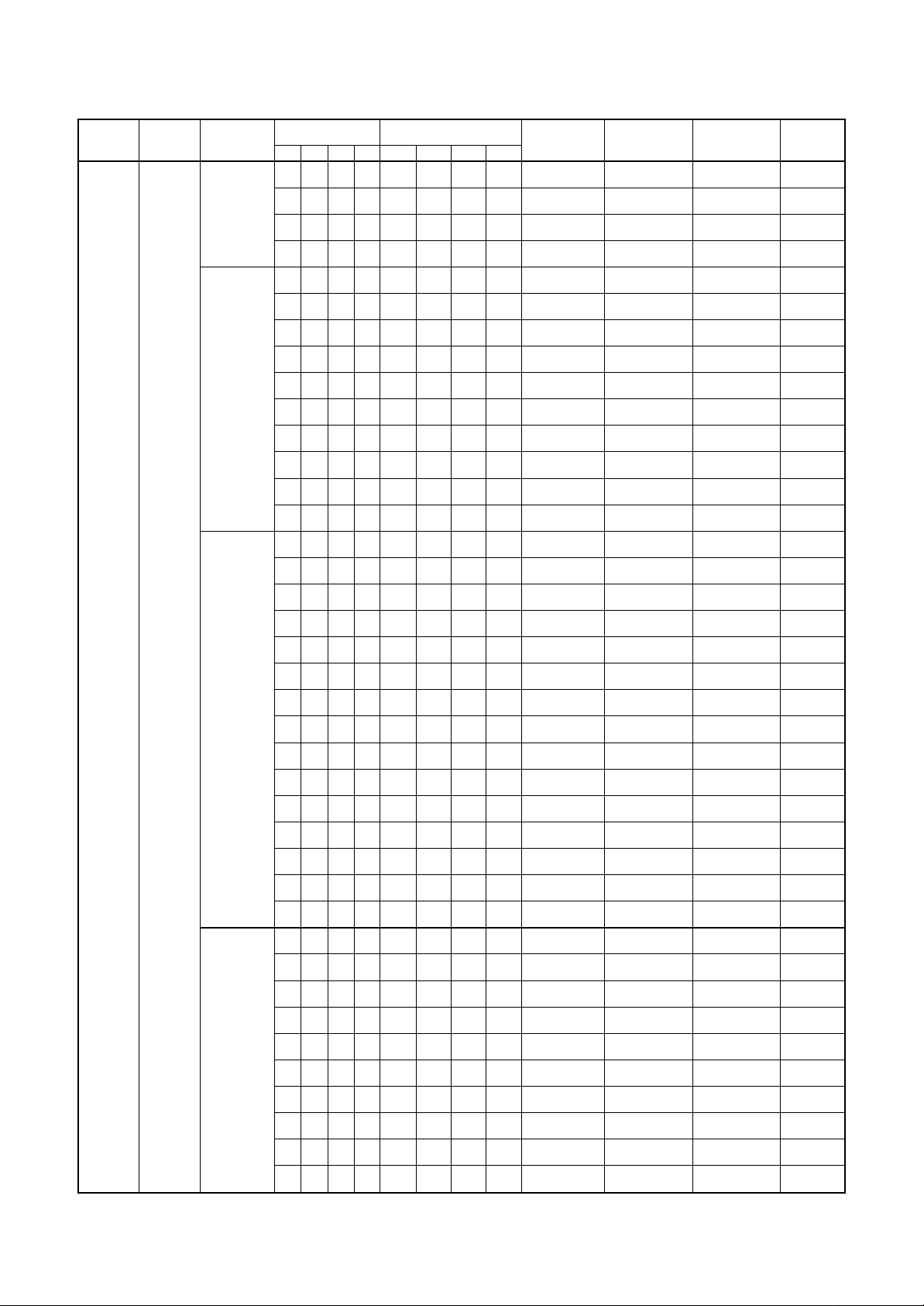
2-2-1. Operation Characteristic Curve
18
16
14
12
10
• Conditions
Indoor : DB27˚C/WB19˚C
Outdoor : DB35˚C
Air flow : High
Pipe length : 5m × 4
4 units operating
8
220V
Current (A)Capacity ratio (%)
6
230V
4
2
0
0
10 20 30 40 50 60 70 80 90
Inverter output frequency (rps)
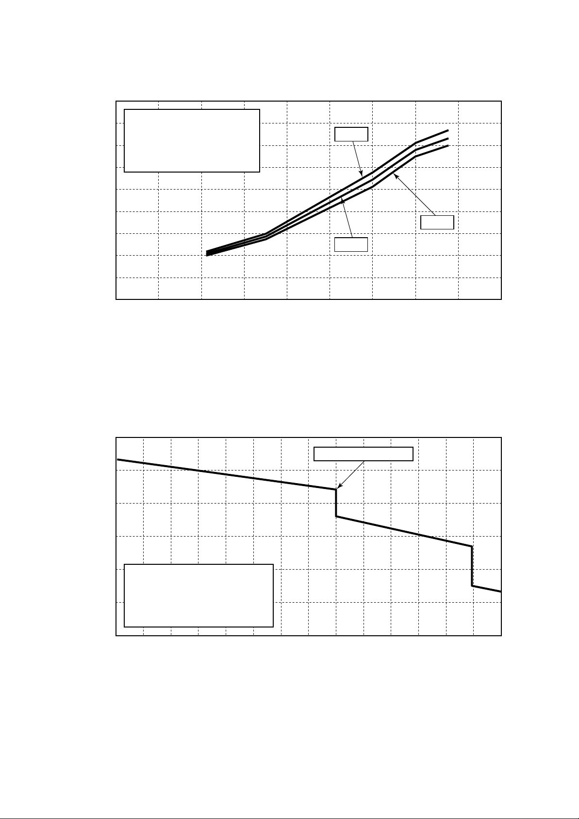
2-2-2. Capacity Variation Ratio According to Outdoor Temperature
240V
110
100
90
80
70
60
50
• Conditions
Indoor : DB27˚C/WB19˚C
Outdoor : DB35˚C
Indoor air flow : High
Pipe length : 5m × 4
4 units operating
33 34 35 36 37 38 39 4032
Current limited start
41 42 43 44 45 46
Outdoor temp. (˚C)
Capacity ratio 100% = 7.5kW
– 12 –

3. REFRIGERANT R410A
This air conditioner adopts the new refrigerant HFC
(R410A) which does not damage the ozone layer.
The working pressure of the new refrigerant R410A
is 1.6 times higher than conventional refrigerant
(R22). The refrigerating oil is also changed in
accordance with change of refrigerant, so be careful
that water, dust, and existing refrigerant or
refrigerating oil are not entered in the refrigerant
cycle of the air conditioner using the new refrigerant
during installation work or servicing.
The next section describes the precautions for air
conditioner using the new refrigerant.
Conforming to contents of the next section together
with the general cautions included in this manual,
perform the correct and safe work.
3-1. Safety During Installation/Servicing
As R410A’s pressure is about 1.6 times higher than
that of R22, improper installation/servicing may
cause a serious problem. By using tools and
materials exclusive for R410A, it is necessary to
carry out installation/servicing safely while taking
the following precautions into consideration.
1. Never use refrigerant other than R410A in an air
conditioner which is designed to operate with
R410A.
If other refrigerant than R410A is mixed, pressure
in the refrigeration cycle becomes abnormally
high, and it may cause personal injury, etc. by a
rupture.
2. Confirm the used refrigerant name, and use
tools and materials exclusive for the refrigerant
R410A.
The refrigerant name R410A is indicated on the
visible place of the outdoor unit of the air
conditioner using R410A as refrigerant.
To prevent mischarging, the diameter of the
service port differs from that of R22.
3. If a refrigeration gas leakage occurs during
installation/servicing, be sure to ventilate fully.
If the refrigerant gas comes into contact with fire,
a poisonous gas may occur.
4. When installing or removing an air conditioner,
do not allow air or moisture to remain in the
refrigeration cycle.
Otherwise, pressure in the refrigeration cycle
may become abnormally high so that a rupture
or personal injury may be caused.
5. After completion of installation work, check to
make sure that there is no refrigeration gas
leakage.
If the refrigerant gas leaks into the room, coming
into contact with fire in the fan-driven heater,
space heater, etc., a poisonous gas may occur.
6. When an air conditioning system charged with a
large volume of refrigerant is installed in a small
room, it is necessary to exercise care so that,
even when refrigerant leaks, its concentr ation
does not exceed the marginal le vel.
If the refrigerant gas leakage occurs and its
concentration exceeds the marginal level, an
oxygen-deficient accident may result.
7. Be sure to carry out installation or removal
according to the installation manual.
Improper installation may cause refrigeration
problem, water leakage, electric shock, fire, etc.
8. Unauthorized modifications to the air conditioner
may be dangerous. If a breakdown occurs
please call a qualified air conditioner technician
or electrician.
Improper repair may result in water leakage,
electric shock and fire, etc.
3-2. Refrigerant Piping Installation
3-2-1. Piping Materials and Joints Used
For the refrigerant piping installation, copper pipes
and joints are mainly used.
Copper pipes and joints suitable for the refrigerant
must be chosen and installed.
Further more, it is necessary to use clean copper
pipes and joints whose interior surfaces are less
affected by contaminants.
1. Copper Pipes
It is necessary to use seamless copper pipes
which are made of either copper or copper alloy
and it is desirable that the amount of residual oil
is less than 40 mg/10 m.
Do not use copper pipes having a collapsed,
deformed or discolored portion (especially on
the interior surface).
Otherwise, the expansion valve or capillar y tube
may become blocked with contaminants.
As an air conditioner using R410A incurs
pressure higher than when using R22, it is
necessary to choose adequate materials.
Thicknesses of copper pipes used with R410A
are as shown in Table 3-2-1.
Never use copper pipes thinner than 0.8 mm
even when it is available on the market.
– 13 –
Table 3-2-1 Thicknesses of annealed copper pipes
Thickness (mm)
Nominal diameter
1/4
3/8
1/2
5/8
Outer diameter (mm)
6.35
9.52
12.70
15.88
R410A R22
0.80 0.80
0.80 0.80
0.80 0.80
1.00 1.00
2. Joints
For copper pipes, flare joints or socket joints are used.
Prior to use, be sure to remove all contaminants.
a) Flare Joints
Flare joints used to connect the copper pipes cannot be used for pipings whose outer diameter exceeds
20 mm. In such a case, socket joints can be used.
Sizes of flare pipe ends, flare joint ends and flare nuts are as shown in Tables 3-2-3 to 3-2-6 below.
b) Socket Joints
Socket joints are such that they are brazed for connections, and used mainly for thick pipings whose
diameter is larger than 20 mm.
Thicknesses of socket joints are as shown in Table 3-2-2.
Table 3-2-2 Minimum thicknesses of socket joints
Nominal diameter
1/4
3/8
1/2
5/8
Reference outer diameter of
copper pipe jointed (mm)
6.35
9.52
12.70
15.88
Minimum joint thickness
(mm)
0.50
0.60
0.70
0.80
3-2-2. Processing of Piping Materials
When performing the refrigerant piping installation, care should be taken to ensure that water or dust does not
enter the pipe interior, that no other oil than lubricating oils used in the installed air-water heat pump is used,
and that refrigerant does not leak.
When using lubricating oils in the piping processing, use such lubricating oils whose water content has been
removed. When stored, be sure to seal the container with an airtight cap or any other cover.
1. Flare processing procedures and precautions
a) Cutting the Pipe
By means of a pipe cutter, slowly cut the pipe so that it is not deformed.
b) Removing Burrs and Chips
If the flared section has chips or burrs, refrigerant leakage may occur.
Carefully remove all burrs and clean the cut surface before installation.
c) Insertion of Flare Nut
– 14 –
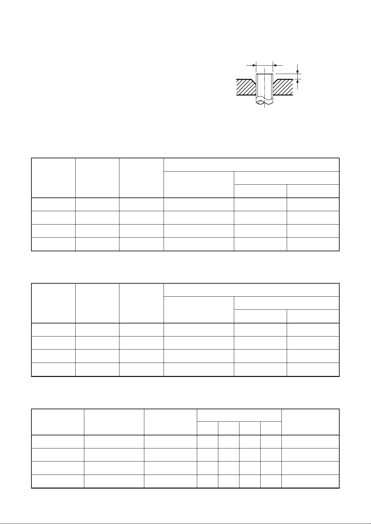
d) Flare Processing
Make certain that a clamp bar and copper
pipe have been cleaned.
By means of the clamp bar, perform the flare
processing correctly.
Use either a flare tool for R410A or
conventional flare tool.
Flare processing dimensions differ according
to the type of flare tool.
When using a conventional flare tool, be sure
to secure “Dimension A” by using a gauge for
size adjustment.
Table 3-2-3 Dimensions related to flare processing for R410A
Nominal
diameter
Outer
diameter
(mm)
Thickness
(mm)
Fig. 3-2-1 Flare pr ocessing dimensions
Flare tool for R410A
clutch type
ØD
A
A (mm)
Conventional flare tool
Clutch type Wing nut type
1/4
3/8
1/2
5/8
Nominal
diameter
1/4
3/8
1/2
5/8
6.35
9.52
12.70
15.88
0.8
0.8
0.8
1.0
0 to 0.5
0 to 0.5
0 to 0.5
0 to 0.5
Table 3-2-4 Dimensions related to flare processing for R22
Outer
diameter
(mm)
6.35
9.52
12.70
15.88
Thickness
(mm)
0.8
0.8
0.8
1.0
Flare tool for R22
clutch type
0 to 0.5
0 to 0.5
0 to 0.5
0 to 0.5
1.0 to 1.5 1.5 to 2.0
1.0 to 1.5 1.5 to 2.0
1.0 to 1.5 2.0 to 2.5
1.0 to 1.5 2.0 to 2.5
A (mm)
Conventional flare tool
Clutch type Wing nut type
0.5 to 1.0 1.0 to 1.5
0.5 to 1.0 1.0 to 1.5
0.5 to 1.0 1.5 to 2.0
0.5 to 1.0 1.5 to 2.0
Nominal
diameter
1/4
3/8
1/2
5/8
Table 3-2-5 Flare and flare nut dimensions for R410A
Outer diameter
(mm)
6.35
9.52
12.70
15.88
Thickness
(mm)
0.8
0.8
0.8
1.0
Dimension (mm)
ABCD
9.1 9.2 6.5 13
13.2 13.5 9.7 20
16.6 16.0 12.9 23
19.7 19.0 16.0 25
– 15 –
Flare nut width
(mm)
17
22
26
29
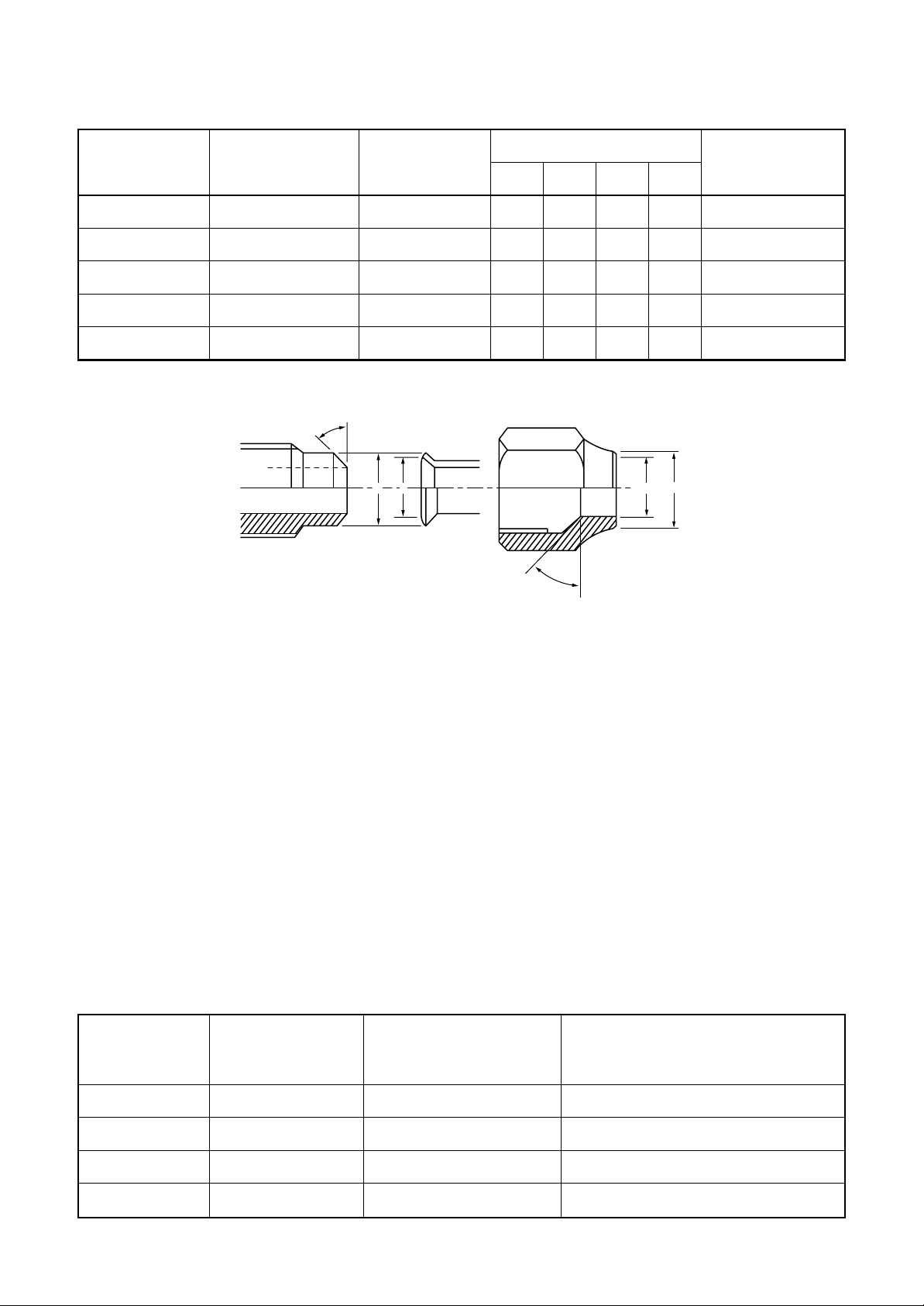
Table 3-2-6 Flare and flare nut dimensions for R22
Nominal
diameter
1/4
3/8
1/2
5/8
3/4
Outer diameter
(mm)
6.35
9.52
12.70
15.88
19.05
45˚ to 46˚
Thickness
(mm)
0.8
0.8
0.8
1.0
1.0
B A
Dimension (mm)
ABCD
9.0 9.2 6.5 13
13.0 13.5 9.7 20
16.2 16.0 12.9 20
19.7 19.0 16.0 23
23.3 24.0 19.2 34
D
C
43˚ to 45˚
Flare nut width
(mm)
17
22
24
27
36
Fig. 3-2-2 Relations between flare nut and flare seal surface
2. Flare Connecting Procedures and Precautions
a) Make sure that the flare and union portions do not have any scar or dust, etc.
b) Correctly align the processed flare surface with the union axis.
c) Tighten the flare with designated torque by means of a torque wrench.
The tightening torque for R410A is the same as that for conventional R22.
Incidentally, when the torque is weak, the gas leakage may occur.
When it is strong, the flare nut may crack and may be made non-removable.
When choosing the tightening torque, comply with values designated by manufacturers.
Table 3-2-7 shows reference values.
Table 3-2-7 Tightening torque of flare for R410A [Reference values]
Nominal
diameter
1/4
Outer diameter
(mm)
6.35
Tightening torque
N•m (kgf•cm)
14 to 18 (140 to 180)
Tightening torque of torque
wrenches available on the market
N•m (kgf•cm)
16 (160), 18 (180)
3/8
1/2
5/8
9.52
12.70
15.88
33 to 42 (330 to 420)
50 to 62 (500 to 620)
63 to 77 (630 to 770)
– 16 –
42 (420)
55 (550)
65 (650)
3-3. Tools
3-3-1. Required T ools
The service port diameter of packed v alve of the outdoor unit in the air-water heat pump using R410A is
changed to prevent mixing of other refrigerant.
To reinforce the pressure-resisting strength, flare processing dimensions and opposite side dimension of flare
nut (For Ø12.7 copper pipe) of the refrigerant piping are lengthened.
The used refrigerating oil is changed, and mixing of oil may cause a trouble such as generation of sludge,
clogging of capillary, etc. Accordingly, the tools to be used are classified into the following three types.
1. Tools exclusive for R410A (Those which cannot be used for conventional refrigerant (R22))
2. Tools exclusive f or R410A, but can be also used for conventional refrigerant (R22)
3. Tools commonly used for R410A and for conventional refrigerant (R22)
The table below shows the tools exclusive for R410A and their interchangeability.
Tools exclusive for R410A (The following tools for R410A are required.)
Tools whose specifications are changed for R410A and their interchangeability
air-water heat pump installation
No.
1
2
3
4
5
6
7
8
9
10
(Note 1) When flaring is carried out for R410A using the conventional flare tools, adjustment of
Used tool
Flare tool
Copper pipe gauge for
adjusting projection
margin
Torque wrench
(For Ø12.7)
Gauge manifold
Charge hose
Vacuum pump adapter
Electronic balance for
refrigerant charging
Refrigerant cylinder
Leakage detector
Charging cylinder
Usage
Pipe flaring
Flaring by
conventional flare tool
Connection of flare nut
Evacuating, refrigerant
charge, run check, etc.
Vacuum evacuating
Refrigerant charge
Refrigerant charge
Gas leakage check
Refrigerant charge
Existence of
new equipment
for R410A
Yes
Yes
Yes
Yes
Yes
Yes
Yes
Yes
(Note 2)
R410A
Whether conventional equipment
can be used
*(Note 1)
*(Note 1)
×
×
×
×
×
×
×
Conventional air-water
heat pump installation
Whether new equipment
can be used with
conventional refrigerant
¡
*(Note 1)
×
×
¡
¡
×
¡
×
projection margin is necessary. For this adjustment, a copper pipe gauge, etc. are necessary.
(Note 2) Charging cylinder for R410A is being currently developed.
General tools (Conventional tools can be used.)
In addition to the above exclusive tools, the following equipments which serve also for R22 are
necessary as the general tools.
1. Vacuum pump
Use vacuum pump by attaching
vacuum pump adapter.
2. Torque wrench (For Ø6.35, Ø9.52)
3. Pipe cutter
4. Reamer
5. Pipe bender
6. Level vial
7. Screwdriver (+, –)
8. Spanner or Monkey wrench
9. Hole core drill (Ø65)
10. Hexagon wrench
(Opposite side 4mm)
11 . Tape measure
12. Metal saw
Also prepare the following equipments for other installation method and run check.
1. Clamp meter
2. Thermometer
3. Insulation resistance tester
4. Electroscope
– 17 –
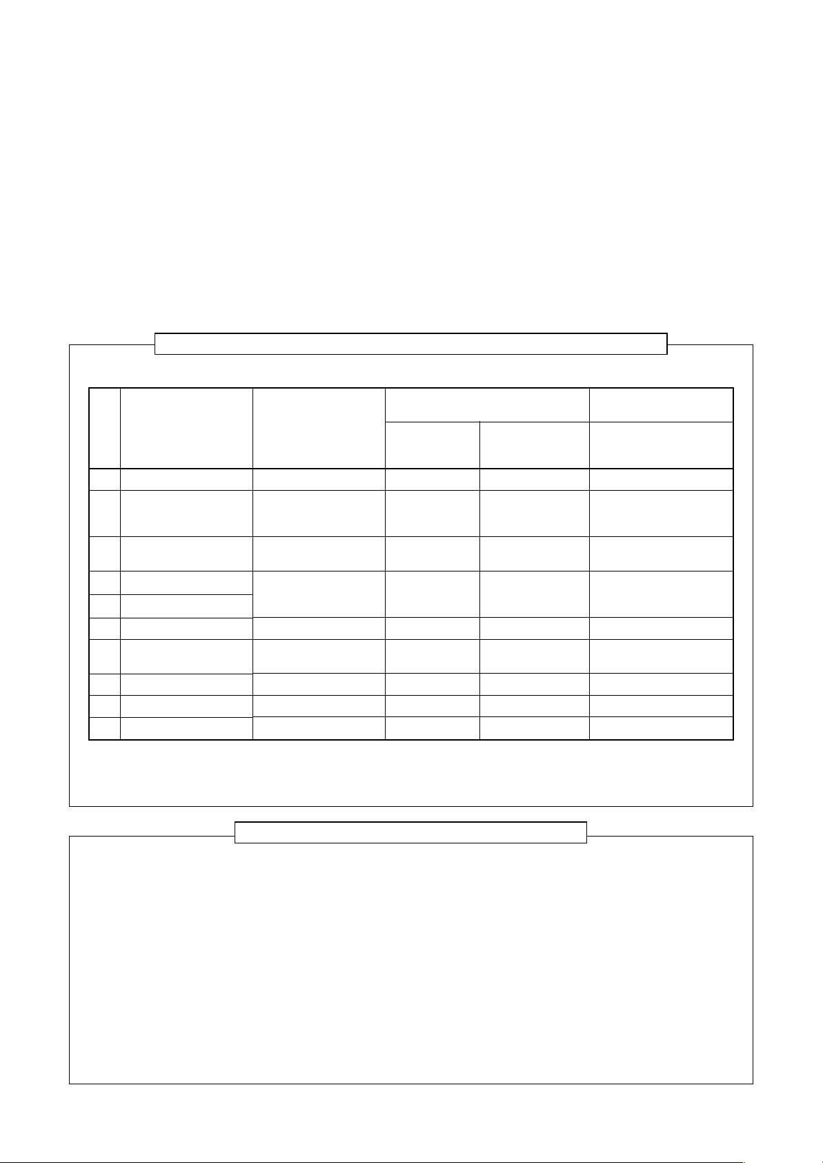
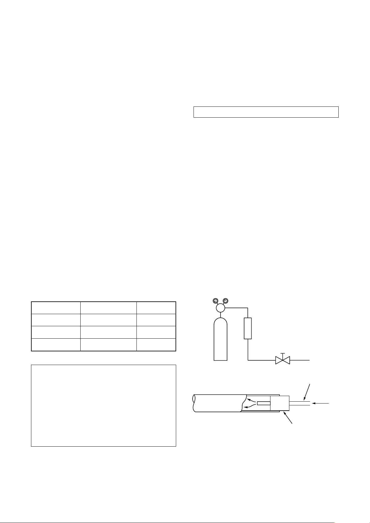
3-4. Recharging of Refrigerant
When it is necessary to recharge refrigerant, charge the specified amount of new refrigerant according to the
following steps .
Recover the refrigerant, and check no refrigerant
remains in the equipment.
Connect the charge hose to packed valve service
port at the outdoor unit’s gas side.
Connect the charge hose to the vacuum pump
adapter.
Open fully both packed valves at liquid and gas
sides.
When the compound gauge’s pointer has indicated
–0.1 Mpa (–76 cmHg), place the handle Low in the
fully closed position, and turn off the vacuum pump’s
power switch.
Keep the status as it is for 1 to 2 minutes, and ensure
that the compound gauge’s pointer does not return.
Set the refrigerant cylinder to the electronic balance,
connect the connecting hose to the cylinder and the
connecting port of the electronic balance, and charge
liquid refrigerant.
Place the handle of the gauge manifold Low in the
fully opened position, and turn on the vacuum pump’s
power switch. Then, evacuating the refrigerant in the
cycle.
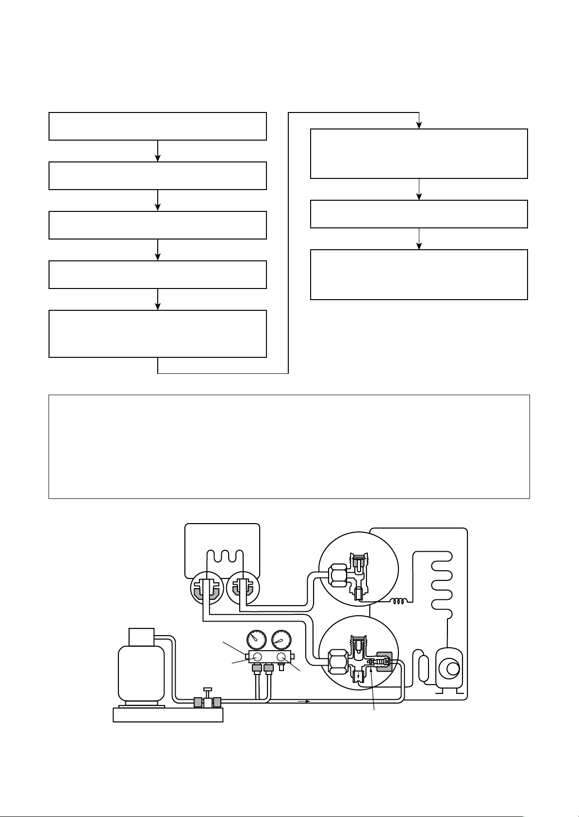
(For refrigerant charging, see the figure below.)
1. Never charge refrigerant e xceeding the specified amount.
2. If the specified amount of refrigerant cannot be charged, charge refrigerant bit by bit in COOL mode.
3. Do not carry out additional charging.
When additional charging is carried out if refrigerant leaks, the refrigerant composition changes in the
refrigeration cycle, that is characteristics of the air conditioner changes, refrigerant exceeding the
specified amount is charged, and working pressure in the refrigeration cycle becomes abnormally high
pressure, and may cause a rupture or personal injury.
(Indoor unit)
Opened
(Outdoor unit)
Refrigerant cylinder
(with siphon)
Check valve
Opened
Open/close
valve for charging
Electronic balance for refrigerant charging
Fig. 3-4-1 Configuration of refrigerant charging
Opened
Closed
Service port
– 18 –
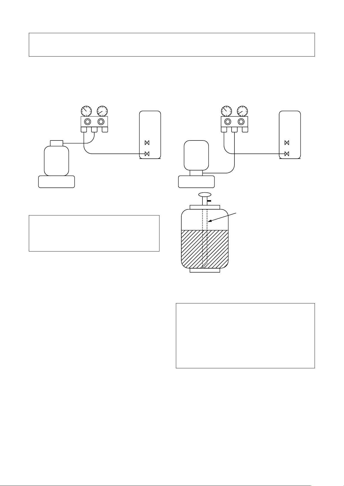
1. Be sure to make setting so that liquid can be charged.
2. When using a cylinder equipped with a siphon, liquid can be charged without turning it upside down.
It is necessary for charging refrigerant under condition of liquid because R410A is mixed type of refrigerant.
Accordingly, when charging refrigerant from the refrigerant cylinder to the equipment, charge it turning the
cylinder upside down if cylinder is not equipped with siphon.
[ Cylinder with siphon ] [ Cylinder without siphon ]
Gauge manifold
OUTDOOR unit
Refrigerant
cylinder
Gauge manifold
OUTDOOR unit
cylinder
Refrigerant
Electronic
balance
R410A refrigerant is HFC mixed refrigerant.
Therefore, if it is charged with gas, the
composition of the charged refrigerant changes
and the characteristics of the equipment varies.
3-5. Brazing of Pipes
3-5-1. Materials for Brazing
1. Silver brazing filler
Silver brazing filler is an alloy mainly composed
of silver and copper. It is used to join iron,
copper or copper alloy, and is relatively
expensive though it excels in solderability.
2. Phosphor bronze brazing filler
Phosphor bronze brazing filler is generally
used to join copper or copper alloy.
Electronic
balance
Siphon
Fig. 3-4-2
1. Phosphor bronze brazing filler tends to react
with sulfur and produce a fragile compound
water solution, which may cause a gas leakage .
Therefore, use any other type of br azing filler at
a hot spring resort, etc., and coat the surface
with a paint.
2. When performing brazing again at time of
servicing, use the same type of brazing filler.
3-5-2. Flux
3. Low temperature brazing filler
Low temperature brazing filler is generally
called solder, and is an alloy of tin and lead.
Since it is weak in adhesive strength, do not
use it for refrigerant pipes.
1. Reason why flux is necessary
• By removing the oxide film and any foreign
matter on the metal surface, it assists the flow of
brazing filler.
• In the brazing process, it prevents the metal
surface from being oxidized.
• By reducing the brazing filler’s surface tension, the
brazing filler adheres better to the treated metal.
– 19 –
2. Characteristics required for flux
• Activated temperature of flux coincides with the
brazing temperature.
• Due to a wide effective temper ature range, flux
is hard to carbonize.
• It is easy to remove slag after brazing.
• The corrosive action to the treated metal and
brazing filler is minimum.
• It excels in coating perf ormance and is harmless to the human body.
As the flux works in a complicated manner as
described above, it is necessary to select an
adequate type of flux according to the type and
shape of treated metal, type of brazing filler and
brazing method, etc.
3. Types of flux
• Noncorrosive flux
Generally, it is a compound of borax and boric
acid. It is effective in case where the brazing
temperature is higher than 800°C.
• Activated flux
Most of fluxes generally used for silver brazing
are this type.
It features an increased oxide film removing
capability due to the addition of compounds
such as potassium fluoride, potassium chloride
and sodium fluoride to the borax-boric acid
compound.
4. Piping materials for brazing and used
brazing filler/flux
3-5-3. Brazing
As brazing work requires sophisticated techniques,
experiences based upon a theoretical knowledge, it
must be performed by a person qualified.
In order to prev ent the oxide film from occurring in
the pipe interior during brazing, it is effective to
proceed with brazing while letting dry Nitrogen gas
(N2) flow.
Never use gas other than Nitrogen gas.
1. Brazing method to prevent oxidation
1) Attach a reducing valve and a flow-meter to
the Nitrogen gas cylinder.
2) Use a copper pipe to direct the piping material, and attach a flow-meter to the cylinder.
3) Apply a seal onto the clearance between the
piping material and inserted copper pipe for
Nitrogen in order to prevent backflow of the
Nitrogen gas.
4) When the Nitrogen gas is flowing, be sure to
keep the piping end open.
5) Adjust the flow rate of Nitrogen gas so that it
is lower than 0.05 m3/Hr or 0.02 MPa
(0.2kgf/cm2) by means of the reducing valve.
6) After performing the steps above, keep the
Nitrogen gas flowing until the pipe cools down
to a certain extent (temperature at which
pipes are touchable with hands).
7) Remove the flux completely after brazing.
Piping material
Copper - Copper
Copper - Iron
Iron - Iron
Used brazing filler
Phosphor copper
Silver
Silver
Used flux
Do not use
Paste flux
Vapor flux
1. Do not enter flux into the refrigeration cycle.
2. When chlorine contained in the flux remains
within the pipe, the lubricating oil
deteriorates.Therefore, use a flux which does
not contain chlorine.
3. When adding water to the flux, use water
which does not contain chlorine (e.g. distilled
water or ion-exchange water).
4. Remove the flux after brazing.
M
Flow meter
Stop valve
Nitrogen gas
cylinder
From Nitrogen cylinder
Pipe
Nitrogen
gas
Rubber plug
Fig. 3-5-1 Pre vention of oxidation during brazing
– 20 –
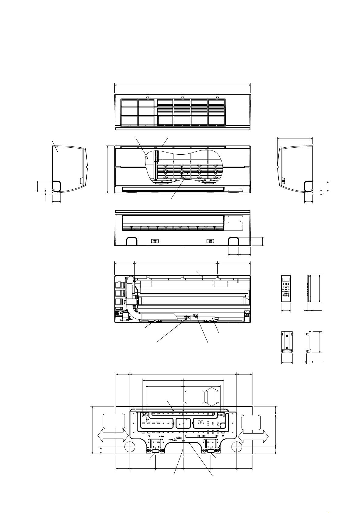
4. CONSTRUCTION VIEWS
4-1. Indoor Unit
RAS-M10SKCV, RAS-M13SKCV, RAS-M16SKCV
790
Front panel
63
7
48
Knock out system
275
Air filter
116
Air inlet
Heat exchanger
480
Installation plate hanger
62 69
193
205
48
Knock out system
49
56
19
Wireless remote controller
63
7
157
Installation plate hanger
Connecting pipe (0.35m)
(For 10,13 series; Flare Ø9.52mm)
(For 16 series; Flare Ø12.7mm)
84.5
235
215
Hanger
Minimum
distance
to wall
170 or more
275
40
84.5 150 84.5
Center line
Drain hose (0.50m)
Connecting pipe (0.40m)
(Flare Ø6.35mm)
621
235
215
Minimum
distance
to ceiling
65
or more
Hanger Hanger
160.5 160.5 150
Installation plate outline
– 21 –
84.5
Minimum
distance
to wall
170 or more
125
63
26
Remote controller holder
45
190
40
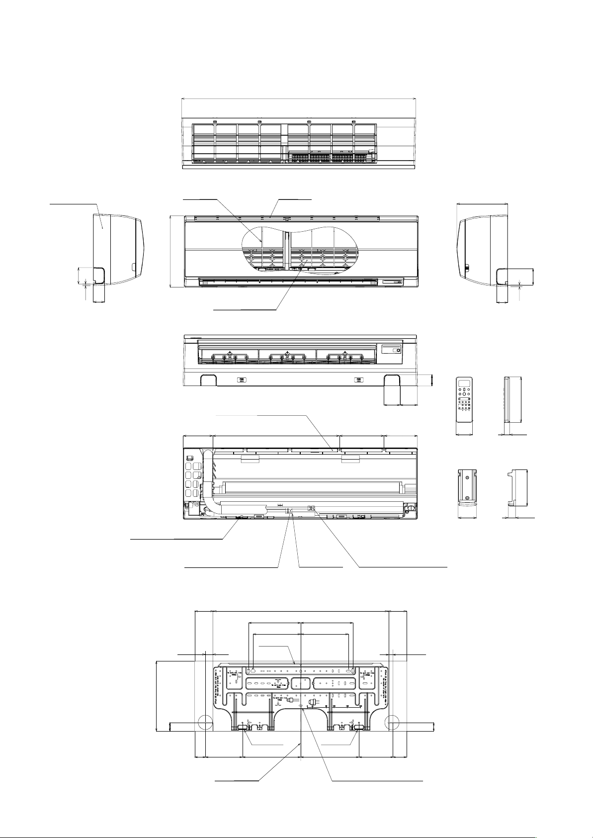
RAS-M22SKCV
1050
Front panel
73.5
7
50
Knock out system Knock out system
Air filter
320
Heat exchanger
Installation plate hanger
132 568 200 150
Air inlet
228
50
50
72 78
56 24
Wireless remote controller
73.5
7
204
Installation plate hanger
Connecting plate (0.39m)
(Flare Ø12.70mm)
132 786
85
320
40
47 215.5 262.5 262.5 153.5 109
Drain hose
(0.5mm)
235
215 215
Hanger
Hanger
Center line Instrallation plate outline
235
Hanger
Connecting pipe (0.49m)
(Flare Ø6.35mm)
132
23
163
82 26
Remote controller holder
40
– 22 –
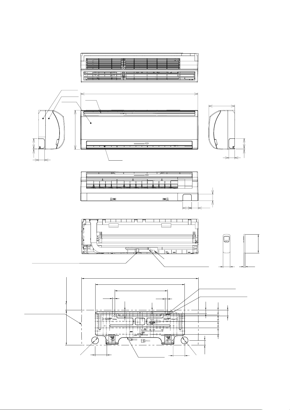
RAS-M22NKCV1
75
7
51
Knock out system
Back body
Front panel
Grille inlet
298
Air inlet
Air outlet
998
75
56
220
Knock out system
50
50
75
8
Connection pipe (0.39 m)
(Flare Ø12.7)
Outline of indoor unit
55 or more
Minimum distance
to ceiling
298
Ø65
100
20
160
Drain hose (0.54 m)
Connection pipe (0.49 m)
(Flare Ø6.35)
57
Wireless remote controller
18
998
48
763.5
450
20
10
(For stud bolt Ø6)
(For stud bolt Ø8 - Ø10)
29
41
48
55
5555
Installation
plate outline
100
Ø65
40
– 23 –
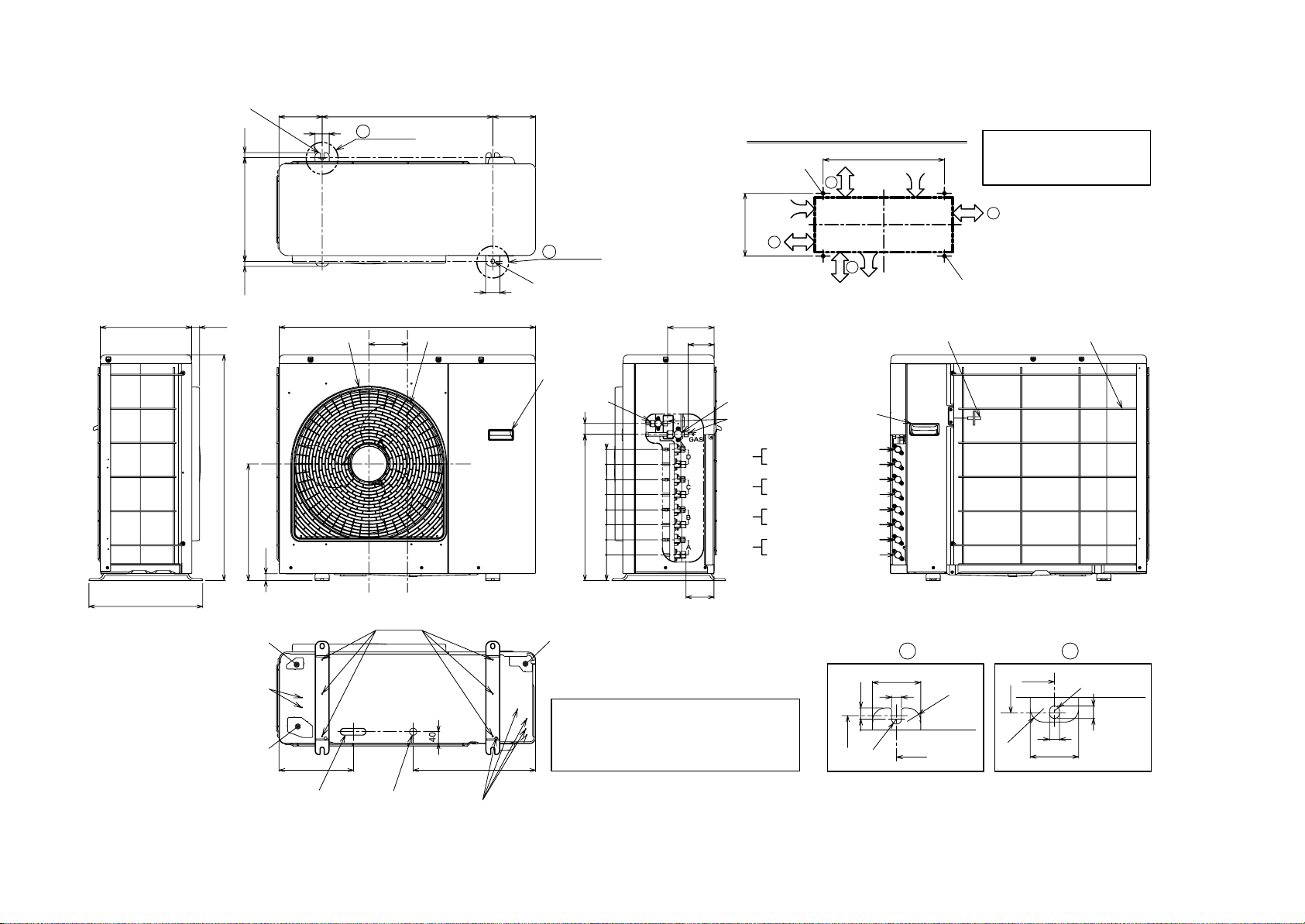
4-2. Outdoor Unit
RAS-4M26SACV
2-dia.12 × 17 U-shape hole
(for dia.8-10 anchor bolt)
17.517.5
365
320
28
150 150
50
Anchor bolt
long hole pitch
A
600
log part
900
Fan guard
136
dia.510
Mounting dimensions of anchor bolt
2-dia.12 × 17 U-shape hole
(for dia.8-10 anchor bolt)
D
600
Intake
100 or more
Intake
100 or more
365
B
log part
50
2-dia.12 × 17 long hole
(for dia.8-10 anchor bolt)
C
600 or more
B
Outlet
Outside line
of product
2-dia.12 × 17 long hole
(for dia.8-10 anchor bolt)
When installing the outdoor unit,
leave open in at least two of
directions (A), (B), (C) and (D)
shown in the figure below.
600 or more
A
(Minimum distance from wall)
164
91
Fan guardOutdoor air temperature sensor
Hanger
Liquid valve
– 24 –
38
795
514
410
25
90 53 53 53 53 53 5353
400
Gas valve
Service port
Connecting pipe port :
D unit
C unit
B unit
A unit
98
Hanger
Connecting pipe dia.6.35
Connecting pipe dia.9.52
Connecting pipe dia.6.35
Connecting pipe dia.9.52
Connecting pipe dia.6.35
Connecting pipe dia.9.52
Connecting pipe dia.6.35
Connecting pipe dia.12.7
Screw
Knock out
2-dia.3.5 hole
Knock out
262 431
Drain long hole
dia.20 × 88 long hole
Drain hole
dia.25
5-dia.3.5 hole
Knock out
Tightly seal the knock-out holes and
screw/thread areas using a silicon adhesive, etc.
to ensure that there is no water drippage.
Under some conditions, comdensation may form
on the base plate and arain, use the drain pan.
Detailed A log part Detailed B log part
365
R20
600
Outside line
of product
R6
17
12
50
units : mm
365
50
12
20
R6
600
R14
Outside line
of product
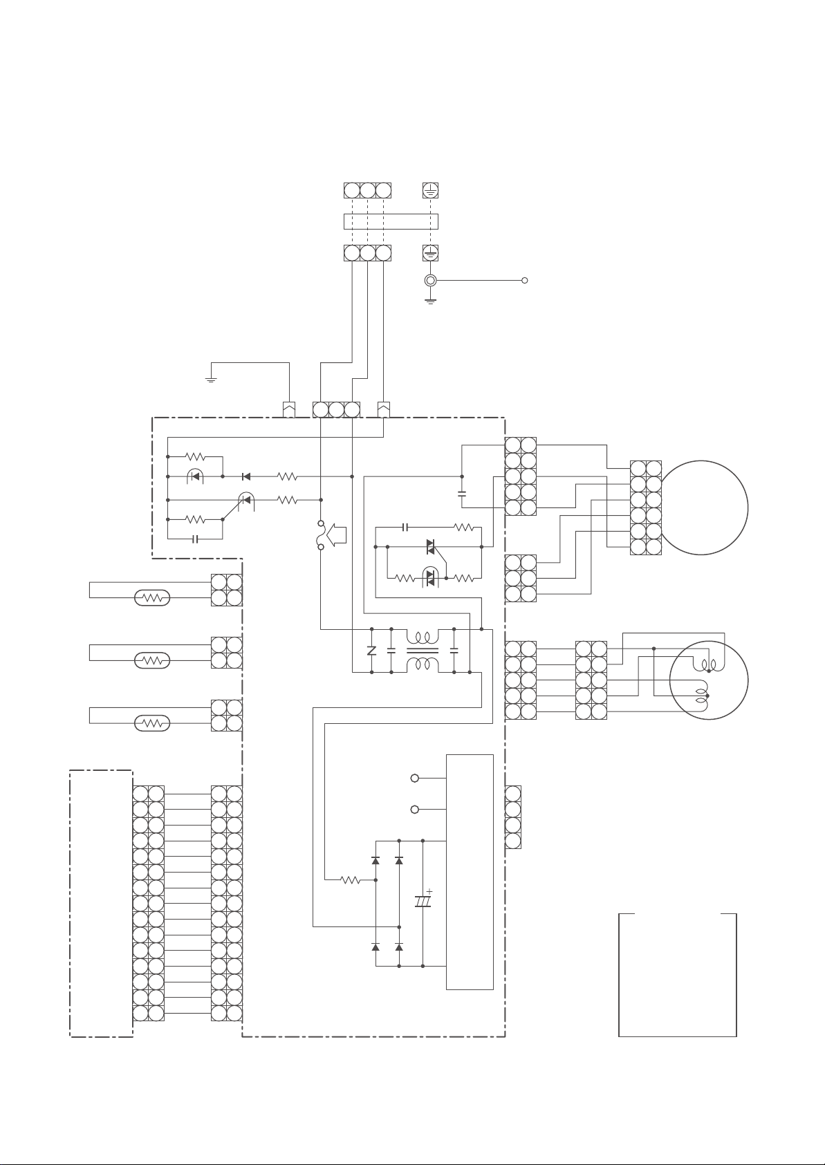
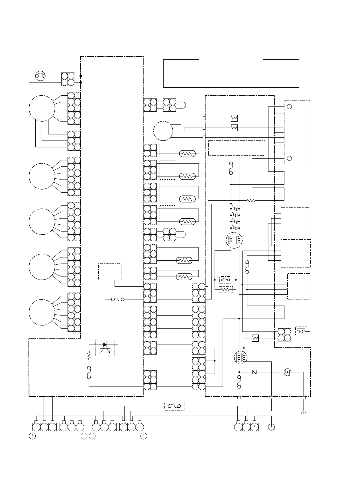
5-1. Indoor Unit
RAS-M10SKCV, RAS-M13SKCV
5. WIRING DIAGRAM
Outdoor terminal block
Indoor terminal block
Power supply
(From Outdoor unit)
1 , 220 240V ~, 50Hz
1 , 220V
Heat exchanger sensor
(TCJ)
1
2
Heat exchanger sensor
(TC)
121
Thermo sensor
(TA)
BLU
1
1
2
2
3
3
4
4
5
5
6
6
7
7
8
8
9
9
MCC-5044
10
10
11
11
12
13
14
15
CN10
(WHI)
12
13
14
15
Wireless unit assembly
BLU
BLU
BLU
BLU
BLU
BLU
BLU
BLU
BLU
BLU
BLU
BLU
BLU
WHI
1
2
3
4
5
6
7
8
9
10
11
12
13
14
15
CN21
(WHI)
~
, 60Hz
Sheet metal
CN02
Fuse F01
T3.15A
11
CN63
(YEL)
22
1
CN62
(BLU)
2
CN61
(WHI)
2
1
2
3
4
5
6
7
8
9
10
11
12
13
14
15
1 2 3
1 2 3
BLK
WHI
BLK
3
1
CN51
CN01
3
Varistor
DC5V
DC12V
Main P.C. board
MCC-5046
RED
Line filter
Heat exchanger
GRN & YEL
1
1
3
3
5
5
CN31
(WHI)
1
1
2
2
3
3
CN33
(WHI)
1
1
2
2
3
3
4
4
5
5
CN32
(WHI)
CN22
(WHI)
1
2
3
4
Power supply circuit
WHI
YEL
YEL
YEL
YEL
6
6
5
5
4
4
AC motor
3
3
2
2
1
1
Fan motor
1
1
2
2
3
3
4
4
5
5
Louver motor
Color
Identification
YEL :
BLK : BLACK
WHI : WHITE
RED : RED
BLU : BLUE
GRN & YEL :
GRAY &
YELLOW
YELLOW
– 25 –
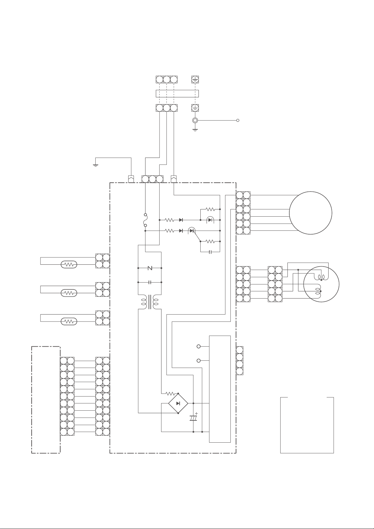
RAS-M16SKCV, RAS-M22SKCV
Outdoor terminal block
Indoor terminal block
Power supply
(From Outdoor unit)
1Ø, 220 – 240V
1Ø, 220V ~, 60Hz
Heat exchanger sensor
(TCJ)
1
2
Heat exchanger sensor
(TC)
121
Thermo sensor
(TA)
BLU
1
1
2
2
3
3
4
4
5
5
6
6
7
7
8
8
MCC-5044
9
9
10
10
11
Wireless unit assembly
11
CN10
(WHI)
BLU
BLU
BLU
BLU
BLU
BLU
BLU
BLU
BLU
WHI
1
2
3
4
5
6
7
8
9
10
11
CN21
(WHI)
Sheet metal
CN02
Fuse F01
T3.15A
AC250V
11
CN63
(YEL)
22
1
CN62
(BLU)
2
CN61
(WHI)
2
1
2
3
4
5
6
7
8
9
10
11
1 2 3
1 2 3
BLK
WHI
~
, 50Hz
BLK
3
1
CN51
CN01
Varistor
Line filter
Main P.C. board
MCC-5045
RED
DC5V
DC12V
~
–
~
Heat exchanger
GRN & YEL
1
1
3
4 4
5
3
5
DC motor
6 6
CN31
(WHI)
1
1
2
2
3
3
4
4
5
5
CN32
(WHI)
CN22
(WHI)
WHI
YEL
YEL
YEL
YEL
1
1
2
2
3
3
4
4
5
5
Fan motor
Louver motor
1
2
3
4
Color
+
Power supply circuit
Identification
YEL :
BLK : BLACK
WHI : WHITE
RED : RED
BLU : BLUE
GRN & YEL :
GRAY &
YELLOW
YELLOW
– 26 –
RAS-M22NKCV1
Louver motor
YEL
WHI
PNK
RED
ORN
6 5 4 3 2 1
6
5 4 3 2 1
BRW
5
CN07
Infrared rays receive
and indication parts
MCC-819
1 2 3 4 5 6 7 8 9
1 2 3 4 5 6 7 8 9
BLU
BLU
BLU
BLU
BLU
BLU
BLU
BLU
1 2 3 4 5 6 7 8 9
1 2 3 4 5 6 7 8 9
4
BLU
10
10
10
10
WHI
CN25
CN14
HA
JEM-A
1 2 3 4
CN08
Outdoor unit
2
BLK
1
WHI
2
RED
3
Indoor
terminal block
GRN & YEL
Indoor unit
CN24
CN23
CN21
T3.15A, 250V
Color
Identification
BRW: BROWN
RED : RED
WHI : WHITE
YEL :
YELLOW
BLU : BLUE
BLK : BLACK
GRY : GRAY
ORN : ORANGE
GRN : GREEN
PNK : PINK
GRN & YEL :
GRAY &
YELLOW
3
F01
1 2 3
1 2 3
CN11
BRW
GRY
YEL
Fan motor
drive circuit
5 3 1
5 3 1
BLK
11223344556
145˚C
Power supply
6
CN10
WHI
RED
6
circuit
Main P.C. board
Thermo.
sensor
AC Fan motor
(WP-004)
1 2
CN03
(WHI)
1 2
BLK
BLK
(TA)
+12V DC
+5V DC
Heat exchanger
sensor
1 2
1 2
BLK
(TC)
BLK
CN01
(BLU)
Simple check points for diagnosing faults
Check item Diagnosis result
1
Operation indicator
2
Terminal block
3
Fuse, 3.15A
4
DC5V
5
DC12V
6
AC220 – 240V
Check to see if the OPERATION indicator goes on and
off when the main switch or breaker is turned on.
Check the power supply voltage between
(Refer to the name plate)
Check the voltage between
Check to see if the fuse blows out.
Check the voltage at the No. 8 pin on CN14 connector
of the infrared receiver.
Check the voltage at the brown lead of the louver motor.
(Check the power supply circuit of the rated voltage.)
Check the voltage at the No. 1 pin of CN10 connector
and CN24. (Check the F01)
For detailed diagnostic procedure, refer to the service data.
and .
and . (AC15 – 60V)
– 27 –
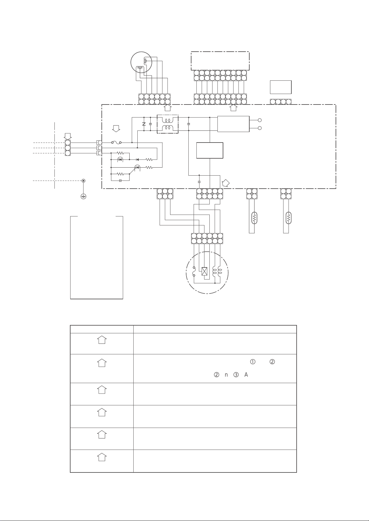
5-2. Outdoor Unit
RAS-4M26SACV
Thermostat for
compressor
ORN
212
ORN
1
Fan motor
FM
PMV
D
PMV
C
PMV
B
PMV
A
SUB P.C. Board
(MCC-818)
F500, Fuse
T6.3A, 250V~
WHI
RED ORN PNK YEL
Color Identification
BLK : BLACK PNK : PINK ORN: ORANGE
P501
P500
5
5
4
4
3
3
CN301
2
2
1
1
3
3
CN300
2
2
1
1
6
6
5
5
4
4
CN704
BLU
3
3
2
2
1
1
CN802
CN608
CN607
CN606
121
Compressor
121
3
1 1
3
1 1
6
6
5
5
4
4
CN703
RED
3
3
2
2
1
1
6
6
5
5
CN702
WHI
4
4
3
3
2
2
1
1
6
6
5
5
4
4
3
3
CN701
2
2
YEL
1
1
Fan
circuit
F300, Fuse
T3.15A, 250V~
CN605
CN604
CN602
CN601
CN302
CN800
Photo coupler
CN303
3
1 1
2 2
1 1
3
1 1
2 2
1 1
3
1
5
4
3
2
1
212
3
CN501
1
BLU : BLUE GRN : GREEN YEL : YELLOW
RED : RED WHI : WHITE PUR : PURPLE
GRY: GRAY BRW : BROWN
RED
2
CM
2
3
121
BLU
GRN
2
RED
WHI
BLK
TGd
TGc
P.C. Board
(MCC-1438)
CN20
CN21
CN22
Power supply circuit
(For P.C. Board)
F04
Fuse
T3.15A
250V~
T03 CT
T04 CT
3
BRW
3
YEL
121
TGb
C13
TGa
2
BLU
C12
C11
C10
3
TD
TO
3
1
5
4
3
2
1
1
BLU
YEL
BLK
WHI
BLU
RED
PNK
PUR
ORN
3
1
5
4
3
2
1
212
3
1
5
4
3
2
1
1
Power
relay
RY02
RB05
CN04
CN06
CN05
F02
Fuse
25A
250V~
T02 CT
5 5
Varistor
F01, Fuse
T25A,
250V~
3
1
Fuse,
T6.3A, 250V~
WHI
RED
3
1 1
3
CN13
CN01P07 P03 P04 P05 P06 CN02 CN03
P20
P19
P18
P17
P13
P12
P09
P08
+
BU
EU
BV
EV
BW
EW
BX
BY
BZ
–
Q200
YEL
BLU
IGBT
G
C
(PFC)
E
Q404
Diode
+
block
~
~
(PFC)
–
DB02
P29
+
P21
Diode
~
P24
~
P28
–
GRY
Reactor
212
1
Surge
absorber
BLKBLKBLK WHI
IGBT module
block
1 2 3 1 2 3 1 2 3 1 2 3
To
Indoor
unit A
To
Indoor
unit B
To
Indoor
unit C
To
Indoor
unit D
– 28 –
WHI
Terminal block
220–240V ~50Hz
220–220V ~60Hz
L N
Power supply
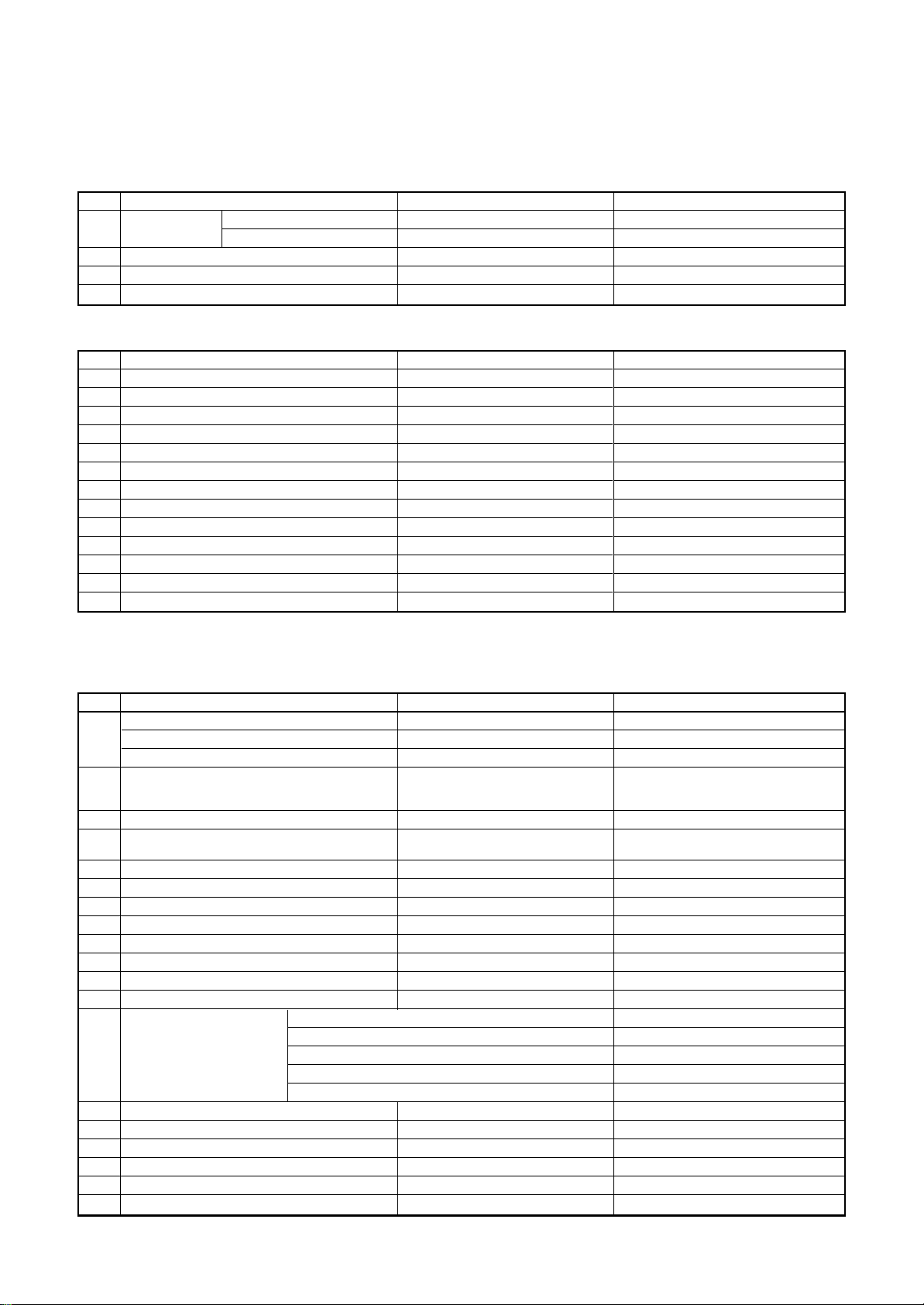
6. SPECIFICATIONS OF ELECTRICAL PARTS
6-1. Indoor Unit
RAS-M10SKCV, RAS-M13SKCV, RAS-M16SKCV, RAS-M22SKCV
No.
Fan motor
1
(for indoor)
2
Room temp. sensor (TA-sensor)
3
Heat exchanger temp. sensor (TC-sensor)
4
Louver motor
RAS-M22NKCV1
No.
1
Fan motor (for indoor)
2
Thermo. sensor (TA-sensor)
3
DC-DC transformer (T01)
4
Microcomputer
5
Heat exchanger temp. sensor (TC-sensor)
6
Line filter (L01)
7
Diode (DB01)
8
Capacitor (C50)
9
Fuse (F01)
10
Regulator IC (IC08)
11
Regulator IC (IC11)
12
Resistor (R21, R109)
13
Louver motor
6-2. Outdoor Unit
Parts name
RAS-M10SKCV, M13SKCV
RAS-M16SKCV, M22SKCV
Parts name
Type
AFS-220-20-4AR
ICF-340-30-2B
( – )
( – )
MP24Z3T
Type
AFS-220-31-4A
( – )
TT-10
µPD780024AGK
( – )
SS11V-06270
KBP06M
LXV35VB2200MJ20
BET 3.15A, AC250V
NJM7812
NJM7805
15G561K
MP35EA12
Specifications
AC240V, 20W
DC340V, 30W
10kΩ at 25°C
10kΩ at 25°C
Output (Rated) 1W, 16 poles, DC12V
Specifications
AC220–240V
10kΩ at 25°C
198-264V, 6VA
10kΩ at 25°C
27µH, AC 0.64A
1.5A, 420V
2200µF, 35V
T3.15A, 250V
DC12V, 1.5A max.
DC5V, 1.5A max
560V
DC12V
RAS-4M26SACV
No.
SC coil (Noise filter) (L01)
1
SC coil (Noise filter) (L02)
SC coil (Noise filter) (L03)
2
DC-DC transformer
3
Outside fan motor
5
Relay (Power relay)
6
Discharge temp. sensor (TD-sensor)
7
Outside air temp. sensor (TO-sensor)
8
Temp. sensor at A room gas side (TGA-sensor)
9
Temp. sensor at B room gas side (TGB-sensor)
10
Temp. sensor at C room gas side (TGC-sensor)
11
Temp. Sensor at D room gas side (TGD-sensor)
12
Ter minal block (6P)
13
Ter minal block (3P)
14
Fuse
15
Electrolytic capacitor
16
Transistor module
17
Compressor
18
Compressor thermo.
19
Diode block (Rectifire)
20
Reactor (Main)
Parts name
Model name
ADR2520R15TB
SC-20-S03J
ADR25H200RBTB
SWT-75
ICF-140-63-2R
G4A-1A-PE
(Inverter attached)
(Inverter attached)
(Inverter attached)
(Inverter attached)
(Inverter attached)
(Inverter attached)
—
—
For protection of switching power source (F04)
For protection of power f actor converter circuit breakage
For protection of inverter input overcurrent
For protection of switching power source (F300)
For protection of power source
LLQ2G761KHUATF
6MBI40SS-060-51A
DA220A2F-20L
US622KXTMQO
S30VT80
CH-47-Z-T
Rating
AC 250V, 20A, 0.15mH
AC 250V, 20A, 0.3mH
AC 250V, 20A, 0.88mH
Primary side DC 240 – 390V
Secondary side : 7V × 1, 13V × 1
DC 140V, 63W
Coil : DC 12V
Contact : 20A, AC250V
64kΩ (20°C)
10kΩ (25°C)
10kΩ (25°C)
10kΩ (25°C)
10kΩ (25°C)
10kΩ (25°C)
AC 250V, 20A
AC 250V, 20A
AC 250V, 3.15A
AC 250V, 25A
AC 250V, 25A
AC 250V, 3.15A
AC 250V, 6.3A
DC 400V, 760µF
600V, 40A
3 phases, 4 poles, 2000W
OFF : 125 ± 4°C, ON : 90 ± 5°C
AC 800V, 30A
L = 8mH, 16A
16V × 3
– 29 –

7. REFRIGERANT CYCLE DIAGRAM
7-1. Indoor Unit and Ourdoor Unit
RAS-M10SKCV, RAS-M13SKCV, RAS-M16SKCV, RAS-M22SKCV, RAS-M22NKCV1 / RAS-4M26SACV
Connecting pipe
Thickness : 0.8mm
Ø12.7 :
RAS-M22NKCV1,
RAS-M16SKCV
RAS-M22SKCV
Ø9.52 :
RAS-M10SKCV,
RAS-M13SKCV
Temp. measurement
To
D room
To
C roomToB room
TGd TGc TGb
T1
Indoor unit A
Evaporator
Cross flow fan
Connecting pipe
Thickness : 0.8mm
Ø6.35
Sectional shape
of heat insulator
TGa
TA
Strainer
TCa
To
D room
(Ø6.35)(Ø9.52) (Ø9.52) (Ø9.52) (Ø12.7) (Ø6.35) (Ø6.35) (Ø6.35)
To
C room
To
B room
Per 1 unit
Max. : 25m
Min. : 2m
Total
Max. :
70m ∗1 or
Allowable height
difference : 15m
50m ∗2
Allowable pipe length
Pulse motor
valve at liquid side
(UKV-18D)
Pressure
P
measurement
Gauge attaching port
Vacuum pump
connecting port
Accumulating tank
1500cc
Temp. measurement
Packed valve (Gas side)
(Ø12.7)
T2
Propeller fan
Outdoor unit
Packed valve (Liquid side)
(Ø9.52)
Muffler
Ø25 x 160L
TD
Compressor
DA220A2F-20L
TO
Refrigerant amount : 2.2kg (R410A)
NOTE : Gas leak check position
Refrigerant flow
NOTE :
∗1 In case of without the RAS-M22SKCV indoor unit.
∗2 In case of with the RAS-M22SKCV indoor unit.
∗∗ The additional charging of refrigerant is unnecessar y because this conditioner is designed with charge-less
specification.
– 30 –

7-2. Operation Data
Temperature
condition
Indoor Outdoor
27 /19 35 / –
No. of
operating
units
1 unit
2 units
3 units
4 units
Operating combination
(Unit)
ABCD
10 –––
13 –––
16 –––
22 –––
10 10 ––
13 10 ––
16 10 ––
13 13 ––
16 13 ––
16 16 ––
10 22 ––
13 22 ––
16 22 ––
22 22 ––
10 10 10 –
13 10 10 –
16 10 10 –
13 13 10 –
16 13 10 –
13 13 13 –
16 16 10 –
16 13 13 –
16 16 13 –
16 16 16 –
22 10 10 –
22 13 10 –
22 13 13 –
22 16 10 –
22 16 13 –
10 10 10 10
13 10 10 10
16 10 10 10
13 13 10 10
16 13 10 10
13 13 13 10
16 13 13 10
16 16 10 10
22 10 10 10
Standard
pressure
P (MPa)
0.8 to 1.0
0.7 to 0.9
0.6 to 0.8
0.7 to 0.9
0.8 to 1.0
0.8 to 1.0
0.8 to 1.0
0.8 to 1.0
0.7 to 0.9
0.7 to 0.9
0.8 to 1.0
0.8 to 1.0
0.8 to 1.0
0.9 to 1.0
0.8 to 1.0
0.8 to 1.0
0.8 to 1.0
0.8 to 1.0
0.8 to 1.0
0.8 to 1.0
0.8 to 1.0
0.8 to 1.0
0.8 to 1.0
0.8 to 1.0
0.8 to 1.0
0.8 to 1.0
0.8 to 1.0
0.8 to 1.0
0.8 to 1.0
0.9 to 1.1
0.9 to 1.1
0.9 to 1.1
0.9 to 1.1
0.9 to 1.1
0.9 to 1.1
0.9 to 1.1
0.9 to 1.1
0.9 to 1.1
Heat exchanger
pipe temp.
T1 (°C) T2 (°C)
9 to 11 45 to 47
8 to 10 46 to 48
7 to 9 47 to 49
8 to 10 48 to 50
10 to 12 47 to 49
10 to 12 48 to 50
10 to 12 49 to 51
10 to 12 50 to 52
9 to 11 51 to 53
9 to 11 52 to 54
10 to 12 50 to 52
10 to 12 50 to 52
10 to 12 50 to 52
11 to 13 51 to 53
11 to 13 51 to 53
11 to 13 51 to 53
11 to 13 51 to 53
11 to 13 51 to 53
11 to 13 52 to 54
11 to 13 52 to 54
11 to 13 52 to 54
12 to 14 52 to 54
12 to 14 52 to 54
12 to 14 52 to 54
11 to 13 49 to 51
11 to 13 50 to 52
11 to 13 51 to 53
11 to 13 52 to 54
11 to 13 52 to 54
12 to 14 51 to 53
12 to 14 51 to 53
12 to 14 52 to 54
12 to 14 52 to 54
12 to 14 52 to 54
12 to 14 53 to 55
12 to 14 53 to 55
12 to 14 54 to 56
12 to 14 53 to 55
Indoor
fan
High
High
High
High
High
High
High
High
High
High
High
High
High
High
High
High
High
High
High
High
High
High
High
High
High
High
High
High
High
High
High
High
High
High
High
High
High
High
Outdoor
fan
MED
MED
MED
MED
MED
MED
MED
MED
MED
MED
MED
MED
MED
MED
MED
MED
MED
MED
MED
MED
MED
MED
MED
MED
MED
MED
MED
MED
MED
MED
MED
MED
MED
MED
MED
MED
MED
MED
Compressor
revolution
(rps)
22
35
45
52
42
45
49
53
58
62
57
57
58
60
60
60
61
61
62
62
62
63
63
63
62
64
66
68
70
62
64
66
67
68
69
70
71
71
NOTE :
Model of indoor unit: RAS-M10SKCV, RAS-M13SKCV, RAS-M16SKCV, RAS-M22NKCV1, RAS-M22SKCV
NOTES :
1. Measure surface temperature of heat exchanger pipe around center of heat exchanger path U bent.
(Thermistor themometer)
2. Connecting piping condition : 5 meters × 4 units (5m/each indoor unit)
– 31 –

8. CONTROL BLOCK DIAGRAM
8-1. Indoor Unit
RAS-M10SKCV, RAS-M13SKCV, RAS-M16SKCV, RAS-M22SKCV
Heat Exchanger Sensor (Tcj)
Heat Exchanger Sensor (Tc)
Room Temperature Sensor (Ta)
Infrared Rays Signal Receiver
and Indication
Initializing Circuit
Clock Frequency
Oscillator Circuit
Power Supply
Circuit
Converter
(D.C circuit)
Noise Filter
M.C.U.
Functions
• 3-minute Delay at Restart for
Compressor
• Fan Motor Starting Control
• Processing
(Temperature Processing)
• Timer
• Serial Signal Communication
• Clean Function
Serial Signal Transmitter/Receiver
Indoor Unit Control Unit
Louver Motor
Louver Motor
Drive Control
Indoor Fan
Motor Control
Indoor
Fan Motor
From Outdoor Unit
220V
~50Hz
~60Hz
220-240V
REMOTE CONTROLLER
Serial Signal Communication
(Operation Command and Information)
Remote Controller
Operation (START/STOP)
Operation Mode Selection
AUTO, COOL, DRY, FAN only
Thermo. Setting
Fan Speed Selection
ON TIMER Setting
OFF TIMER Setting
Louver AUTO Swing
Louver Direction Setting
ECO
Hi POWER
Infrared Rays, 36.7kHz
COMFORT SLEEP
QUIET
– 32 –

8-2. Outdoor Unit (Inverter Assembl y)
RAS-4M26SACV
Gas side pipe temp. sensorOutdoor air temp. sensor Discharge temp. sensor
A unit PMV
B unit PMV
C unit PMV
D unit PMV
Driver circuit
of PMV
Rotor position
detect circuit
Inverter
(DC ® AC)
• Inverter outdoor frequency control
• A/D converter function
• PMV control
• Discharge temp. control
• Error display
• Signal communication to M.C.U.
• PWM synthesis function
Gate
drive circuit
M.C.U
MCC-818 (SUB-P.C. B)
A unit send/
receive circuit
B unit send/
receive circuit
C unit send/
receive circuit
D unit send/
receive circuit
Clock frequency
oscillator circuit
16MHz
Outdoor
fan motor
Over current
sensor
Over current
detect circuit
Noise filter
Input current
sensor
Converter
(AC ® DC)
Over current
sensor
Clock frequency
oscillator circuit
10MHz
High power factor
correction circuit
Over current
detect circuit
Signal communication
to MCU
220–240V ~50Hz
220V ~60Hz
MCC-1438 (MAIN-P.C. B)
M.C.U
• PWM synthesis function
• Input current release control
• IGBT over current detect control
• High power factor correction control
• Signal communication to M.C.U.
• Output current release control
• A/D converter function
Compressor
Inverter
(DC ® AC)
Output current
sensor
Gate drive
circuit
PMV : Pulse motor valve
PWM : Pulse width modulation
IGBT : Insulated gate bipolar transistor
– 33 –

9. OPERATION DESCRIPTION
9-1. Outline of Air Conditioner Control
This air conditioner is a capacity-variable type air
conditioner, which uses AC or DC motor for the indoor
fan motor and the outdoor fan motor.
And the capacity-proportional control compressor
mounted.
The DC motor drive circuit is mounted to the indoor unit.
The compressor and the inverter to control fan motor
are mounted to the outdoor unit.
The entire air conditioner is mainly controlled by the
indoor unit controller.
The indoor unit controller drives the indoor fan motor
based upon command sent from the remote controller,
and transfers the operation command to the outdoor
unit controller.
The outdoor unit controller receives operation command from the indoor unit side, and controls the
outdoor fan and the pulse motor valve. (P.M.V)
Besides, detecting revolution position of the compressor motor, the outdoor unit controller controls speed of
the compressor motor by controlling output voltage of
the inverter and switching timing of the supply power
(current transfer timing) so that motors drive according
to the operation command.
And then, the outdoor unit controller transfers reversely
the operating status information of the outdoor unit to
control the indoor unit controller.
As the compressor adopts four-pole brushless
DC motor, the frequency of the supply power
from inverter to compressor is 2 times cycles of
the actual number of revolution.
1. Role of indoor unit controller
The indoor unit controller judges the operation
commands from the remote controller and assumes
the following functions.
• Judgment of suction air temperature of the indoor
heat exchanger by using the indoor temp. sensor.
(TA sensor)
• Judgment of the indoor heat exchanger temperature by using heat exchanger sensor (TC sensor)
(Prevent-freezing control, etc.)
• Louver motor control
• Indoor fan motor operation control
• LED (Light Emitting Diode) display control
• Transferring of operation command signal (Serial
signal) to the outdoor unit
• Reception of information of operation status
(Serial signal including outside temp. data) to the
outdoor unit and judgment/display of error
• Detection of inverter input current and current
release operation
• Over-current detection and prevention operation
to IGBT module (Compressor stop function)
• Compressor and outdoor fan stop function when
serial signal is off (when the serial signal does not
reach the board assembly of outdoor control by
trouble of the signal system)
• Transferring of operation information (Serial
signal) from outdoor unit controller to indoor unit
controller
• Detection of outdoor temperature and operation
revolution control
3. Contents of operation command signal
(Serial signal) from indoor unit controller to
outdoor unit controller
The following three types of signals are sent from
the indoor unit controller.
• Operation mode set on the remote controller
• Compressor revolution command signal defined
by indoor temperature and set temperature
(Correction along with variation of room temperature and correction of indoor heat exchanger
temperature are added.)
• Temperature of indoor heat exchanger
• For these signals ([Operation mode] and
[Compressor revolution] indoor heat exchanger
temperature), the outdoor unit controller monitors
the input current to the inverter, and performs the
followed operation within the range that current
does not exceed the allowable value.
4. Contents of operation command signal
(Serial signal) from outdoor unit controller
to indoor unit controller
The following signals are sent from the outdoor unit
controller.
• The current operation mode
• The current compressor revolution
• Outdoor temperature
• Existence of protective circuit operation
For transferring of these signals, the indoor unit
controller monitors the contents of signals, and
judges existence of trouble occurrence.
Contents of judgment are described below.
• Whether distinction of the current operation
status meets to the operation command signal
• Whether protective circuit operates
When no signal is received from the outdoor
unit controller, it is assumed as a trouble.
2. Role of outdoor unit controller
Receiving the operation command signal (Serial
signal) from the indoor unit controller, the outdoor
unit performs its role.
• Compressor operation control
• Operation control of outdoor fan motor
• PMV control
Operations followed to judgment
of serial signal from indoor side.
– 34 –

9-2. Operation Description
9-2. 1. Basic operation....................................................................................................................... 36
1. Operation control ............................................................................................................... 36
2. Cooling operation .............................................................................................................. 37
3. AUTO operation ................................................................................................................. 37
4. DRY operation ................................................................................................................... 37
2. Indoor fan motor control.......................................................................................................... 38
<In cooling operation> ............................................................................................................ 38
3. Outdoor fan motor control....................................................................................................... 39
4. Capacity control...................................................................................................................... 40
5. Current release control........................................................................................................... 40
6. Louver control......................................................................................................................... 4 1
1) Louver position .................................................................................................................. 41
2) Air direction adjustment ..................................................................................................... 41
3) Swing ................................................................................................................................. 41
7. ECO operation........................................................................................................................ 42
1. Indoor unit.......................................................................................................................... 42
2. Outdoor unit....................................................................................................................... 4 2
8. Temporary operation............................................................................................................... 42
9. Self-cleaning function
(RAS-M10SKCV, RAS-M13SKCV, RAS-M16SKCV, RAS-M22SKCV) ................................... 43
10. Self-cleaning operation cancel
(RAS-M10SKCV, RAS-M13SKCV, RAS-M16SKCV,RAS-M22SKCV) .................................... 45
11. Remote-A or B selection
(RAS-M10SKCV, RAS-M13SKCV, RAS-M16SKCV, RAS-M22SKCV) ................................... 46
Remote-A or B selection (RAS-M22NKCV1).......................................................................... 47
12. QUIET mode........................................................................................................................... 48
13. COMFORT SLEEP ................................................................................................................. 48
14. Short timer (RAS-M10SKCV, RAS-M13SKCV, RAS-M16SKCV, RAS-M22SKCV) ................ 48
15. One-Touch comfort (RAS-M10SKCV, RAS-M13SKCV, RAS-M16SKCV, RAS-M22SKCV).... 49
16. Hi POWER mode.................................................................................................................... 49
17. FILTER indicator (RAS-M10SKCV, RAS-M13SKCV, RAS-M16SKCV, RAS-M22SKCV)........ 49
FILTER indicator (RAS-M22NKCV1) ...................................................................................... 49
9-3. Auto Restart Function
(RAS-M10SKCV, RAS-M13SKCV, RAS-M16SKCV, RAS-M22SKCV) ..................... 50
9-3-1. How to Set the Auto Restart Function ................................................................................ 50
9-3-2. How to Cancel the Auto Restart Function.......................................................................... 51
9-3-3. Power Failure During Timer Operation ............................................................................... 51
9-4. Auto Restart Function (RAS-M22NKCV1) .............................................................52
9-4-1. How to Set the Auto Restart Function ................................................................................ 52
9-4-2. How to Cancel the Auto Restart Function.......................................................................... 53
9-4-3. Power Failure During Timer Operation ............................................................................... 53
9-5. Remote Controller
(RAS-M10SKCV, RAS-M13SKCV, RAS-M16SKCV, RAS-M22SKCV) ..................... 54
9-5-1. Remote Controller and Its Functions.................................................................................. 54
9-5-2. Operation of Remote Controller .......................................................................................... 54
9-5-3. Name and Functions of Indications on Remote Controller .............................................. 57
9-6. Remote Controller (RAS-M22NKCV1).................................................................... 58
9-6-1. Remote Controller and Its Functions.................................................................................. 58
9-6-2. Name and Functions of Indications on Remote Controller .............................................. 59
– 35 –

Item
Operation flow and applicable data, etc.
Description
1. Basic
operation
1. Operation control
Receiving the user’s operation condition setup, the operation statuses of indoor/outdoor units are
controlled.
1) The operation conditions are selected by the remote controller as shown in the below.
2) A signal is sent by ON button of the remote controller.
3) The signal is received by a sensor of the indoor unit and processed by the indoor controllers as
shown in the below.
4) The indoor controller controls the indoor fan motor and louver motor.
5) The indoor controller sends the operation command to the outdoor controller, and sends/receives
the control status with a serial signal.
6) The outdoor controller controls the operation as shown in the below, and also controls the
compressor, outdoor fan motor and pulse motor valve.
Selection of
operation conditions
ON/OFF
Remote controller
Control contents of remote controller
• ON/OFF
• Operation select
• Temperature setup
• Air direction
• Swing
• Air volume select (AUTO/LOW/LOW+/MED/MED+/HIGH)
• ECO
• ON timer setup
• OFF timer setup
• High power
• COMFORT SLEEEP
• QUIET
• PRESET
• ONE-TOUCH
Signal receiving
Indoor unit control
Operation command
Serial signal send/receive
Serial signal send/receive
Outdoor unit control
Indoor unit
Indoor unit control
• Command signal generating function of indoor unit
operation
• Calculation function (temperature calculation)
• Activation compensation function of indoor fan
• Timer function
• Indoor heat exchanger release control
Outdoor unit
Outdoor unit control
• Frequency control of inverter output
• Waveform composite function
• Calculation function
(Temperature calculation)
• AD conversion function
• Delay function of compressor reactivation
• Current release function
• GTr over-current preventive function
Inverter
• Indoor fan motor
• Louver motor
~
• Compressor
• Outdoor fan motor
• Pulse motor valve
(PMV)
– 36 –

Item
Operation flow and applicable data, etc.
Description
1. Basic
operation
2. Cooling operation
The operation is performed in the following parts by controls according to cooling conditions.
1) Receiving the operation ON signal of the remote controller, the cooling operation starts
according to the signal transferred from the indoor controller to the outdoor unit.
2) At the indoor unit side, the indoor fan is operated according to the contents of “2. Indoor fan
motor control” and the louver according to the contents of “6. Louver control”, respectively.
3) The outdoor unit controls the outdoor fan motor, compressor, pulse motor valve according to the
operation signal sent from the indoor unit.
Operation ON
Indoor unit control
Sending of operation command signal
Outdoor unit control
3. AUTO operation
Selection of operation mode
As shown in the following figure, the operation starts by
selecting automatically the status of room temperature
(Ta) when star ting AUTO operation.
*1.When reselecting the operation mode, the fan speed
is controlled by the previous operation mode.
Setup of remote controller
Indoor fan motor control / Louver control
Compressor revolution control /
Outdoor fan motor control
Pulse motor valve control
1) Detects the room temperature (Ta)
when the operation started.
2) Selects an operation mode from Ta in
the left figure.
3) Fan operation continues until an
operation mode is selected.
4) Then, select an operation mode.
Ta
Cooling operation
Ts + 1
Monitoring (Fan)
Ts – 1
Monitoring (Fan)
4. DRY operation
DRY operation is performed according to the difference
between room temperature and the setup temperature
as shown below.
In DRY operation, fan speed is controlled in order to
prevent lowering of the room temperature and to avoid
air flow from blowing directly to persons.
[˚C]
+
Ta
1.0
L– (W5)
(W5+W3) / 2
+
0.5
1) Detects the room temperature (Ta) when
the DRY operation started.
2) Starts operation under conditions in the
left figure according to the temperature
difference between the room temperature and the setup temperature (Tsc).
Setup temperature (Tsc)
= Set temperature on remote controller
(Ts) + (0.0 to 1.0)
3) When the room temperature is lower
1°C or less than the setup temperature,
turn off the compressor.
Tsc
SUL (W3)
Fan speed
– 37 –

Item
Operation flow and applicable data, etc.
Description
2. Indoor fan
motor control
RAS-M10SKCV
RAS-M13SKCV
RAS-M16SKCV
RAS-M22SKCV
RAS-M22NKCV1
<In cooling operation>
(This operation controls the fan speed at indoor unit side.)
The indoor fan (cross flow fan) is operated by the phase-
control induction motor. The fan rotates in 5 stages in
MANUAL mode, and in 5 stages in AUTO mode, respectively.
(Table 1)
COOL ON
Fan speed setup
AUTO
Air volume AUTO
Ta
[˚C]
+2.5
a
+2.0
b
+1.5
c
+1.0
MANUAL
Indication
L
L+
M
M+
H
M+(WB)
∗3
∗4
∗5
(Fig. 1)
Fan speed
W6
(L + M) / 2
W9
(M + H) / 2
WC
(Fig. 2)
∗3 : Fan speed =
{(M +) –L} × 3/4 + L
∗4 : Fan speed =
{(M +) –L} × 2/4 + L
∗5 : Fan speed =
{(M +) –L} × 1/4 + L
* Symbols
UH : Ultra High
H : High
M+ : Medium+
M : Medium
L+ : Low+
L: Low
L- : Low–
UL : Ultra Low
SUL : Super Ultra Low
∗ The fan speed broadly varies due
to position of the louver, etc.
The described value indicates one
under condition of inclining
downward blowing.
1) When setting the fan speed to L,
L+, M, M+ or H on the remote
controller, the operation is
performed with the constant
speed shown in Fig. 1.
2) When setting the fan speed to
AUTO on the remote controller,
revolution of the fan motor is
controlled to the fan speed level
shown in Fig. 2 and Table 1
according to the setup temperature, room temperature, and heat
exchanger temperature.
+0.5
Fan
speed
level
WF
WE
WD
WC
WB
WA
W9
W8
W7
W6
W5
W4
W3
W2
W1
Tsc
d
e
COOL
UH
H
M+
M
L+
L
L–
UL
SUL
DRY
L+
L
L–
UL
SUL
RAS-M10SKCV
Fan speed
rate (rpm)
1240 630
1170 582
1140 563
1100 536
1000 469
1000 469
960 443
870 383
850 369
760 309
760 309
700 269
650 236
500 135
500 135
L(W6)
(Linear approximation
from M+ and L)
(Ta ble 1) Indoor fan air flow rate
RAS-M13SKCV
Air flow
(m3/h)
Fan speed
rate (rpm)
1240 630
1240 630
1190 596
1140 563
1040 496
100 469
960 443
870 383
850 369
760 309
760 309
700 269
650 236
500 135
500 135
Air flow
(m3/h)
Fan speed
rate (rpm)
RAS-M16SKCV
Air flow
(m3/h)
1470 743
1470 743
1440 723
1390 691
1250 601
1190 563
1120 518
970 421
950 408
890 370
870 357
810 318
750 280
600 183
500 119
RAS-M22SKCV
Fan speed
rate (rpm)
1200 1101
1200 1101
1200 1101
1180 1079
1080 968
1020 902
980 858
850 713
810 669
800 658
760 614
700 547
650 492
500 325
500 325
Air flow
(m3/h)
RAS-M22NKCV1
Fan speed
rate (rpm)
1300 850
1230 790
1150 750
1050 650
1000 610
900 530
900 530
850 490
Air flow
(m3/h)
——
——
——
——
——
——
——
– 38 –

Item
Operation flow and applicable data, etc.
Description
3. Outdoor fan
motor control
1) Outdoor unit
The blowing air volume at the outdoor unit side is controlled.
Receiving the operation command from the controller of indoor
unit, the controller of outdoor unit controls fan speed.
* For the fan motor, a DC motor with non-stage variable speed
system is used.
However, it is limited to 8 stages for reasons of controlling.
Air conditioner ON
(Remote controller)
Indoor unit controller
operation command
(Outdoor fan control)
2) Fan speed ³ 400
when the motor stopped.
YES
OFF status of
fan motor continues.
NO
Fan motor ON
1) The operation command sent
from the remote controller is
processed by the indoor unit
controller and transferred to the
controller of the outdoor unit.
2) When strong wind blows at
outdoor side, the operation of air
conditioner continues with the
fan motor stopped.
3) Whether the fan is locked or not
is detected, and the operation of
air conditioner stops and an
alarm is displayed if the fan is
locked.
4) According to each operation
mode, by the conditions of
outdoor temperature (To) and
compressor revolution, the speed
of the outdoor fan shown in the
table is selected.
3) Fan lock
YES
Air conditioner
OFF
NO
4) Motor operates as shown in the table below.
Cooling operation, dry operation
Compressor revolution (rps)
>
TO
Outdoor temp. sensor
TO
Econo operation
TO is abnormal
TO < 38°C
38°C
1 to 2 units
3 to 4 units
>
TO
38°C
TO < 38°C
Alarm
display
20.3 ~50.3 ~71.2 71.2~
390 (rpm) 770 (rpm) 770 (rpm) 770 (rpm)
390 (rpm) 670 (rpm) 670 (rpm) 770 (rpm)
390 (rpm) 510 (rpm) 670 (rpm) 770 (rpm)
390 (rpm) 670 (rpm) 670 (rpm) 670 (rpm)
390 (rpm) 670 (rpm) 670 (rpm) 670 (rpm)
510 (rpm) 670 (rpm) 670 (rpm) 670 (rpm)
TO : Outdoor temperature sensor
– 39 –

Item
Operation flow and applicable data, etc.
Description
4. Capacity
control
1) Four indoor units from A to D determine the respective instruction revolutions from the
difference between the remote controller setting temperature (Ts) and the indoor temperature
(Ta), and transmit this to the outdoor unit.
2) The outdoor unit receives the instructions from the indoor units, and the inverter operates the
compressor at the calculated revolutions.
3) The compressor operation range in each operating mode is shown in the table below.
Indoor unit A
Indoor unit B
Indoor unit C
Indoor unit D
Operation mode
COOL
operating unit
No.of
1 unit
2 units
3 units
4 units
Outdoor unit
Inverter
Compressor
Combination
of indoor units
M10
M13
M16
M22
∗
¡
∗
¡
∗
¡
Compressor revolution
(rps)
15 to 28
15 to 43
15 to 53
15 to 62
15 to 66
23 to 72
23 to 77
5. Current release
control
Outdoor unit inverter main
circuit control current
Operating current ≤
Setup value
Yes
Capacity control continues.
Outdoor temp.
∗ : In case that any multiple indoor units are combined.
This function prevents troubles on the electronic parts of the
compressor driving inverter.
This function also controls drive circuit of the compressor
speed so that electric power of the compressor drive circuit
does not exceed the specified value.
Outdoor temp. To
Setup of current release point
No
Reduce compressor speed
Current decrease
Cooling current release value
1) The input current of the outdoor
unit is detected in the inverter
section of the outdoor unit.
2) According to the detected
outdoor temperature, the
specified value of the current is
selected.
3) Whether the current value
exceeds the specified value or
not is judged.
4) If the current value exceeds the
specified value, this function
reduces the compressor speed
and controls speed up to the
closest one commanded from the
indoor unit within the range
which does not exceed the
specified value.
45°C
40°C
44.5°C
39.5°C
7.35A
9.60A
14.2A
– 40 –

Item
Operation flow and applicable data, etc.
Description
5. Current release
control
<Maximum current switch>
Please be reminded that all air conditioners installed at HDB flats are subjected to an amp
restriction of 11 A.
It is the installer’s responsibility to have the current release control set correctly for the type of
HDB flat in which the IMS unit is installed.
The figure below shows how the connector can be arranged for the appropriate setting.
Maximum current switch connector
6. Louver control
1) Louver
position
RAS-M10SKCV,
RAS-M13SKCV,
RAS-M16SKCV,
RAS-M22SKCV
This function controls the air direction of the indoor unit.
• The position is automatically controlled according to the
operation mode.
• The set louver position is stored in memor y by the microcomputer, and the louver returns to the stored position when the
next operation is performed.
The angle of the louver is indicated as the closes fully is 0°.
Louver position in cooling operation
Mis-wiring (Mis-piping) check connector
(color: red)
Maximum current switch connector
(color: blue)
11 A
Full operation (Delivery)
Open
short
2) Air direction adjustment
3) Swing
• Swing operation is performed in width 35° with the stop
position as the center.
• If the stop position exceeds either upper or lower limit position,
swing operation is performed in width 35° from the limit which
the stop position exceeded.
Initial setting of “Cooling storage position”Louver :
Directs downward (35.3˚)
Air direction
Horizontal
blowing
Inclined
blowing
Blowing
downward
– 41 –
Inclined
blowing
• The louver position can be
arbitrarily set up by pushing
[FIX] button.
Horizontal
blowing
• Swing
When pushing [SWING]
button during operation, the
louver starts swinging.

Item
Operation flow and applicable data, etc.
Description
7. ECO
operation
When pushing [ECO] button on the remote controller, an
Economic operation is performed.
1. Indoor unit
<Cooling operation>
This function operates the air conditioner with the
difference between the set and the room temperature as
shown in the following figure.
+6.5
+6.0
+5.5
+5.0
+4.5
+4.0
+3.5
+3.0
+2.5
+2.0
+1.5
+1.0
+0.5
TSC
–0.5
–1.0
–2.0
1H 2H 3H 4H Time
<Cooling operation>
1) The control target temperature
increases 0.5°C per hour up to 2°C
starting from the set temperature when
ECONO has been received.
2) The indoor fan speed is depend on
presetting and can change every speed
after setting ECO operation.
ZoneTA
Frequency
Dry Mac
12
11
10
9
8
7
6
5
4
3
2
1
∗12
∗11
∗10
∗9
∗8
Min
Hz
OFF
FAN
and can change every speed.
Fan speed depends on presetting
12 (DRY max - COOL min) / 6 x 5 + COOL min.
∗
∗ 11 (DRY max - COOL min) / 6 x 4 + COOL min.
∗ 10 (DRY max - COOL min) / 6 x 3 + COOL min.
Hz
Cool min.
DRY max.
2. Outdoor unit
While the indoor units operate in two or more rooms in cooling mode, if ECO operation is selected in
one room at least, the maximum revolution speed of the compressor is limited to 68 rps.
8. Temporary
operation
Pushing [RESET] button starts the temporary operation of
[AUTO] operation. When keeping [RESET] button pushed
for 10 seconds or more, the temporary [COOL] operation
is performed.
Filter lamp ON
NO
Did you push [RESET] button
for 3 seconds or more?
YES
Did you push [RESET] button
for 10 seconds or more?
NO
Switch to [AUTO RESTART] control.
∗ 9 (DRY max - COOL min) / 6 x 2 + COOL min.
∗ 8 (DRY max - COOL min) / 6 x 1 + COOL min.
M10SKCV M13SKCV M16SKCV M22SKCV M22NKCV1
10 10 10 10 10
35 37 35 50 34
1) When pushing [RESET] button, the
temporary [AUTO] operation starts.
2) When keeping [RESET] button pushed
for 3 seconds or more, “beep” sound is
heard and [AUTO RESTART] control is
changed.
YES
Push RESET button.
3) When keeping [RESET] button pushed
for 10 seconds or more, “beep” sound is
heard and the temporary [COOL]
NO
Temporary [AUTO] operation
operation starts.
4) If the filter lamp goes on, push [RESET]
button to go off the filter lamp, and then
push [RESET] button again.
YES
5) To stop the temporary operation, push
the button again.
Temporary [COOL] Operation
– 42 –

Item
Operation flow and applicable data, etc.
Description
9. Self-cleaning
function
RAS-M10SKCV,
RAS-M13SKCV,
RAS-M16SKCV,
RAS-M22SKCV
Unit now performing cooling or dry operation
Push STOP button
Only timer indicator lights, and Self-cleaning operation starts
Time set now elapses
Operation stops
1. Purpose
The Self-cleaning operation is to minimize
the growth of mold, bacteria etc. by
running the fan and drying so as to keep
the inside of the air conditioner clean.
Self-cleaning operation
When the cooling or dry operation shuts
down, the unit automatically starts the
Self-cleaning operation which is then
performed for the specified period based
on duration of the operation which was
performed prior to the shutdown, after
which the Self-cleaning operation stops.
2. Operation
1) When the stop signal from the remote
controller or timer-off function is
received, only the timer indicator lights.
2) The period of the Self-cleaning
operation is determined by the duration
of the operation performed prior to the
reception of the stop code.
3) After the Self-cleaning operation has
been performed for the specified
period, the unit stops operating.
• During Self-cleaning operations:
The louver opens slightly.
Self-clean operation times
Operation mode
Cooling: Auto (cooling) Dry
Auto (fan only)
Shutdown
Operation time Self-cleaning operation time
Up to 10 minutes
10 minutes or longer 30 mins.
No Self-cleaning operation performed
No Self-cleaning operation
performed (0 minutes)
• To stop an ongoing Self-cleaning operation at any time
Push the start/stop button on the remote controller twice during the Self-cleaning operation.
(After pushing the button for the first time, push it for the second time without delay
(within 10 minutes).)
– 43 –

Item
Operation flow and applicable data, etc.
Description
9. Self-cleaning
• Self-cleaning diagram
function
RAS-M10SKCV,
RAS-M13SKCV,
RAS-M16SKCV,
RAS-M22SKCV
Operation
display
FCU fan
FCU louver
Timer display
Compressor
CDU fan
ON OFF OFF
rpm is depend on presetting. (500 rpm)
depend on presetting ON depend on presetting
depend on presetting per OFF OFF
depend on presetting per OFF OFF
Cool mode or dry mode
operation more than 10 mins.
ON ON OFF
OPEN OPEN (12.7°) CLOSE
ON or OFF ON or OFF
of timer function. of timer function.
ON or OFF
room temperature.
ON or OFF
room temperature.
Self-cleaning mode
operate 30 mins.
Turn off by remote controller
or timer-off function.
Automatically turn-off.
Operation time
– 44 –

Item
Operation flow and applicable data, etc.
Description
10. Self-cleaning
operation cancel
RAS-M10SKCV,
RAS-M13SKCV,
RAS-M16SKCV,
RAS-M22SKCV
Setting the clean operation cancel
Add J201 of the indoor P.C. board assembly.
* This cancels the auto restart function.
Hold down the [RESET] button on the indoor unit
for at least 3 seconds but not more than 10 seconds.
The indoor unit’s buzzer emits three beeps.
This completes the clean operation cancel setting.
Setting the clean operation
Hold down the [RESET] button on the indoor unit
for at least 3 seconds but not more than 10 seconds.
NOTE:
Once J201 is added, the [RESET]
button on the unit is designated for
CLEAN OPERATION (Set/Cancel),
therefore the [RESET] button can
not be used for the selection
(Set/Cancel) of AUTO RESTART
function.
∗ J201 will be near the MCU so take
steps to ensure that it will not be
exposed to excessive of heat.
Also take care to avoid solder
bridging with the surrounding
components.
The indoor unit’s buzzer emits three beeps, and
the OPERATION indicator flashes at 5 Hz intervals.
This completes the clean operation setting.
Indoor P.C. board
J201
C24
– 45 –

Item
Operation flow and applicable data, etc.
Description
11. Remote-A or B
selection
RAS-M10SKCV,
RAS-M13SKCV,
RAS-M16SKCV,
RAS-M22SKCV
Setting the remote- A or B selection.
To separate using of remote controller for each indoor
unit in case of two air conditioners are installed nearly.
1. Remote Controller B Setup.
1) Push RESET button on the indoor unit to turn the
air conditioner ON.
2) Point the remote controller at the indoor unit.
3) Push and hold CHK button on the Remote
Controller by the tip of the pencil.
“00” will be shown on the display.
4) Push MODE button during pushing CHK button.
“B” will show on the display and “00” will disappear
and the air conditioner will turn OFF.
The Remote Controller B is memorized.
Note :
1. Repeat above step to reset Remote Controller to be A.
2. Remote Controller A has not “A” display.
3. Default setting of Remote Controller from factory is A.
“B” Display
1. Purpose
This operation is to operate only
one indoor unit using one remote
controller.
2. Description
When operating one indoor unit in
a situation where two indoor units
have been installed in the same
room or nearby rooms, this
operation prevents the remote
controller signal from being
received simultaneously by both
units, thus preventing both units
from operating.
3. Operation
The indoor unit on which the
remote controller selection has
been set to B receives the signal of
the remote controller also set to B.
(At the factory the remote controller
selection is set to A on all the indoor
units. There is no A setting display.)
AUTO
“00” Display
2. Setting the unit
1) Push the RESET button to star t automatic
operation on indoor unit.
2) Push the
was set in step 1 to stop the air
conditioner.
(This operation will change the setting to “B”.)
3) Check that the remote controller operates the
indoor unit.
button of the remote controller that
– 46 –

Item
Operation flow and applicable data, etc.
Description
11. Remote-A or B
selection
(RAS-M22NKCV1)
Setting the remote controller
To separate using of remote controller for each
indoor unit in case of two air conditioners are
installed nearly.
Remote Controller B Setup.
• Enter the battery.
• Push the [CHK] button by something with thin
edge. ([00] is displayed.)
• If [MODE] button is pushed while pushing [CHK]
button, the small [B] is displayed at the right of the
setting temperature indication section.
* To reset [A] setting, push the [MODE] button
again while pushing the [CHK] button.
1. Purpose
This operation is to operate only one
indoor unit using one remote controller.
2. Description
When operating one indoor unit in a
situation where two indoor units have
been installed in the same room or
nearby rooms, this operation prevents
the remote controller signal from
being received simultaneously by
both units, thus preventing both units
from operating.
3. Operation
The indoor unit on which the remote
controller selection has been set to B
receives the signal of the remote
controller also set to B.
(At the factory the remote controller
selection is set to A on all the indoor
units. There is no A setting display.)
[MODE] button
[CHK] button
Indoor unit B Setup.
1) Tu rn the circuit breaker of the main power switch off before setting the selector switch.
2) Remove the Air inlet grille and Front panel.
(Refer to Chapter 12-1, procedure
3) Open the Electrical part cover (Refer to Chapter 12-1, procedure
the jumper (J67) with only the nippers for B setting.
, page 112)
, page 114), then cut
CAUTION
Do not use any other sharp tools (such as cutters, pliers, or the like).
Such tools may cause breakage or damage.
– 47 –

Item
Operation flow and applicable data, etc.
Description
12. QUIET mode
13. COMFORT
SLEEP
1. Indoor unit
When the [QUIET] button is pushed, the fan
of the indoor unit will be restricted the
revolving speed at speed L-until the
[QUIET] button is pushed once again
(cancel Quiet mode).
2. Outdoor unit
While the indoor units operate in two or
more rooms in cooling mode, if QUIET
mode is selected in one room at least, the
maximum revolution speed of the compressor is limited to 73 rps.
1. Indoor unit
• The preset temperature will increase as
show on ECO operation (Item No. 7)
• Push the [COMFORT SLEEP] button to
choose the operating hours.
Repeat pushing to select the hours.
(1hr, 3hr, 5hr or 9hr)
• If the [COMFORT SLEEP] button is
pushed again means cancel comfort
sleep mode.
2. Outdoor unit
While the indoor units operate in two or
more rooms in cooling mode, if Comfort
Sleep is selected in one room at least, the
maximum revolution speed of the compressor is limited to 73 rps.
Quiet mode is the system which controls the
revolving speed of indoor fan to work constantly
at lower than speed L.
In addition, noise level of indoor unit is less
than usual.
Remarks :
1. Quiet mode is unable to work in dry mode.
2. Quiet mode is appropriate to work with less
cooling load and less heating load condition.
Because of the fan speed L- may cause not
enough the cooling capacity.
The principles of comfort sleep mode are:
• Quietness for more comfortable when room
temperature reaches setting temperature.
• Save energy by changing room temperature
automatically.
• The air condition can shut down by itself
automatically.
Remarks:
1. Comfort sleep mode will not operate in dry
mode and fan only mode.
14. Short timer
RAS-M10SKCV,
RAS-M13SKCV,
RAS-M16SKCV,
RAS-M22SKCV
In the normal condition, after switching on the
circuit breaker, 3-minute delay time for
compressor is set.
PRESET
ONE-TOUCH
QUIET
SWING
TIMER
SLEEP
CHK
FAN
TEMP
MODE
COMFORT
SLEEP
FIX Hi-POWER ECO
ON
OFF
FILTER
CLOCK
Purpose
To start the unit immediately for the pur pose of
testing, trial...etc, short timer can be used for
maintenance of the unit.
Short Timer Setting
Push [ ] button to tur n the unit OFF.
Set the operation mode or plasma air
purifier on the remote controller without
sending the signal to the unit.
Use the tip of the pencil to push the [CHK]
button and hold, “00” will show on display,
then push [SET] button to make “00”
disappear.
Push [ ] button to turn the unit ON.
When short timer is activated, all setting on
the remote indicates immediately, besides,
4
CLR
SET
all indicatiors on front panel turn ON
continuously for 3 seconds.
– 48 –
3

Item
Operation flow and applicable data, etc.
Description
15. One-Touch
comfort
RAS-M10SKCV,
RAS-M13SKCV,
RAS-M16SKCV,
RAS-M22SKCV
One touch comfort is the fully automated operation that
is set according to the preferable condition in a region.
Fan
operation
* AUTO/L: Fan operates depending on the setting
temperature and room temperature.
During the One Touch Comfort mode if the indoor unit
receives any signal with other operation mode, the unit
will cancel the comfort mode and operates according
to the signal received.
16. Hi POWER mode
([Hi POWER] button on the remote controller is pushed)
When [Hi POWER] button is pushed while the indoor unit is in Auto, Hi POWER mark is
indicated on the display of the remote controller and the unit operates as follows.
1. Automatic operation
• The indoor unit operates according to the current operation.
2. Cooling operation
• The preset temperature drops 1°C
(The value of the preset temperature on the remote controller does not change.)
The indoor unit’s fan speed level increases 1 tap.
3. The Hi POWER mode cannot be set in Dry operation.
AUTO
*AUTO/L L
01225
Time after operation starts
(min.)
When an indoor unit receives
“One T ouch Comfort Signal” from
the remote controller, the indoor unit
operates as follows.
1) Air conditioner starts to operate
when the signal is received, even
if the air conditioner was OFF.
2) Operation mode is set according
to room temperature, the same
as AUTO mode.
3) Target temperature is 24°C.
4) Louver position is set as stored
position of the operating mode.
5) Fan is controlled as shown in the
leftf.
17. FILTER indicator
RAS-M10SKCV,
RAS-M13SKCV,
RAS-M16SKCV,
RAS-M22SKCV
When the elapsed time reaches 1000 hours the FILTER indicator lights.
After cleaning the filters, turn off the FILTER indicator.
How to Turn Off FILTER Indicator
Push [RESET] button on the indoor unit.
NOTE :
If [RESET] button is pushed while the FILTER indicator is not lit, the indoor unit will start the
automatic operation.
When you want a temporary operation while the FILTER lamp lights, push [RESET] button to
turn off the FILTER lamp. (See page 42)
17. FILTER indicator
(RAS-M22NKCV1)
Filter check lamp
When the elapsed time reaches 1000 hours, the filter check lamp indicates.
After cleaning the filters, turn off the filter check lamp.
How to turn off filter check lamp
Push [RESET] button on the indoor unit.
NOTE :
If [RESET] button is pushed while the filter check lamp is not indicating, the indoor unit will start
the Automatic Operation.
– 49 –

9-3. Auto Restart Function
(RAS-M10SKCV, RAS-M13SKCV, RAS-M16SKCV, RAS-M22SKCV)
This indoor unit is equipped with an automatic restarting function which allows the unit to restart operating with
the set operating conditions in the event of a power supply being accidentally shut down.
The operation will resume without warning three minutes after power is restored.
This function is not set to work when shipped from the factory. Therefore it is necessary to set it to work.
9-3-1. How to Set the Auto Restart Function
To set the auto restart function, proceed as follows:
The power supply to the unit must be on ; the function will not set if the power is off.
Push the [RESET] button located in the center of the front panel continuously for 3 seconds.
The unit receives the signal and beeps 3 times.
The unit then restarts operating automatically in the event of power supply being accidentally shut down.
• When the unit is standby (Not operating)
Operation
Push [RESET] button for more than
3 seconds. (Less than 10 seconds)
Hi POWER FILTER PAP TIMER OPERATION
RESET
• When the unit is in operation
Operation
Push [RESET] button for more than
3 seconds. (Less than 10 seconds)
Motions
The unit is on standby.
↓
The unit starts to operate. The green indicator is on.
↓ After approx. 3 seconds,
The unit beeps 3 times The green indicator flashes
and continues to operate. for 5 seconds.
If the unit is not required to operate at this time, push [RESET]
button once more or use the remote controller to turn it off.
Motions
The unit is in operation. The green indicator is on.
↓
The unit stops operating. The green indicator is turned off.
↓ After approx. 3 seconds,
The unit beeps 3 times. The green indicator flashes
for 5 seconds.
Hi POWER FILTER PAP TIMER OPERATION
If the unit is required to operate at this time, push [RESET] button
RESET
once more or use the remote controller to turn it on.
• While the filter check indicator is on, the RESET button has the function of filter reset button.
– 50 –

9-3-2. How to Cancel the Auto Restart Function
To cancel auto restart function, proceed as follows :
Repeat the setting procedure : the unit receives the signal and beeps 3 times.
The unit will be required to be turned on with the remote controller after the main power supply is turned off.
• When the system is on standby (not operating)
Operation
Push [RESET] button for more than
3 seconds. (Less than 10 seconds)
Hi POWER FILTER PAP TIMER OPERATION
RESET
• When the system is operating
Operation
Push [RESET] button for more than
3 seconds. (Less than 10 seconds)
Motions
The unit is on standby.
↓
The unit starts to operate. The green indicator is on.
↓ After approx. 3 seconds,
The unit beeps 3 times and continues to operate.
If the unit is not required to operate at this time, push [RESET]
button once more or use the remote controller to turn it off.
Motions
The unit is in operation. The green indicator is on.
↓
The unit stops operating. The green indicator is turned off.
↓ After approx. 3 seconds,
The unit beeps 3 times.
Hi POWER FILTER PAP TIMER OPERATION
If the unit is required to operate at this time, push [RESET] button
once more or use the remote controller to turn it on.
RESET
9-3-3. P ower Failure During Timer Operation
When the unit is turned off because of power failure during timer operation, the timer operation is cancelled.
In that case, set the timer operation again.
NOTE :
The Everyday Timer is reset while a command signal can be received from the remote controller even if it
stopped due to a power failure.
– 51 –

9-4. Auto Restart Function (RAS-M22NKCV1)
This indoor unit is equipped with an automatic restarting function which allows the unit to restart operating with
the set operating conditions in the event of a power supply being accidentally shut down.
The operation will resume without warning 3 minutes after power is restored.
This function is not set to work when shipped from the factory. Therefore it is necessary to set it to work.
9-4-1. How to Set the Auto Restart Function
To set the auto restart function, proceed as follows:
The power supply to the unit must be on ; the function will not set if the power is off.
Push the [RESET] button located in the center of the front panel continuously for 3 seconds.
The unit receives the signal and beeps 3 times.
The unit then restarts operating automatically in the event of power supply being accidentally shut down.
• When the unit is standby (Not operating)
Operation
Push [RESET] button for more than
3 seconds.
RESET
RESET
TEMPORARY button
0
3S
• When the unit is in operation
Operation
Push [RESET] button for more than
3 seconds.
Motions
The unit is on standby.
↓
The unit starts to operate. The green indicator is on.
↓ After approx. 3 seconds,
The unit beeps 3 times The lamp changes from
and continues to operate. green to orange.
If the unit is not required to operate at this time, push [RESET]
button once more or use the remote controller to turn it off.
Motions
The unit is in operation. The green indicator is on.
↓
The unit stops operating. The green indicator is turned off.
↓ After approx. 3 seconds,
RESET
RESET
TEMPORARY button
0
3S
The unit beeps 3 times.
If the unit is required to operate at this time, push [RESET] button
once more or use the remote controller to turn it on.
• While the function is being set, if the unit is in operation, the orange lamp is on.
• This function can not be set if the timer operation has been selected.
• When the unit is turned on by this function, the louver will not swing even though it was swinging automatically before shutting down.
• While the filter check lamp is on, the [RESET] button has the function of filter reset button.
– 52 –

9-4-2. How to Cancel the Auto Restart Function
To cancel auto restart function, proceed as follows :
Repeat the setting procedure : the unit receives the signal and beeps 3 times.
The unit will be required to be turned on with the remote controller after the main power supply is turned off.
• When the unit is on standby (not operating)
Operation
Push [RESET] button for more than
3 seconds.
RESET
RESET
TEMPORARY button
0
3S
• When the unit is operating
Operation
Push [RESET] button for more than
3 seconds.
Motions
The unit is on standby.
↓
The unit starts to operate. The orange lamp is on.
↓ After approx. 3 seconds,
The unit beeps 3 times The lamp changes
and continues to operate. from orange to green.
If the unit is not required to operate at this time, push [RESET]
button once more or use the remote controller to turn it off.
Motions
The unit is in operation. The orange lamp is on.
↓
The unit stops operating. The orange lamp is turned off.
↓ After approx. 3 seconds,
RESET
RESET
TEMPORARY button
0
3S
The unit beeps 3 times.
If the unit is required to operate at this time, push [RESET] button
once more or use the remote controller to turn it on.
• While this function is being set, if the unit is in operation, the orange lamp is on.
9-4-3. P ower Failure During Timer Operation
When the unit is in Timer operation, if it is turned off because of power failure, the timer operation is cancelled.
Therefore, set the timer operation again.
– 53 –

9-5. Remote Controller (RAS-M10SKCV, RAS-M13SKCV, RAS-M16SKCV, RAS-M22SKCV)
5
3
5
2
9-5-1. Remote Controller and Its Functions
1 Infrared signal emitter
2 Start/Stop button
3 Mode select button (MODE)
4 Temperature button (TEMP .)
5 Fan speed button (FAN)
6 Swing louver button (SWING)
7 Set louver button (FIX)
8 ON timer button (ON)
9 OFF timer button (OFF)
10 Sleep timer button (SLEEP )
11 Setup button (SET)
12 Clear button (CLR)
13 Memory and P reset button (P RESET)
14 One touch button (ONE-TOUCH)
15 High power button (Hi-P OWER)
16 Economy button (ECO)
17 Quiet button (QUIET)
13
14
17
6
8
21
2
7
10
19
PRESET
ONE-TOUCH
QUIET
SWING
TIMER
SLEEP
CHK
1
FAN
TEMP
MODE
COMFORT
SLEEP
FIX Hi-POWER ECO
ON
OFF
FILTER
CLOCK
4
18
1
16
CLR
SET
1
9
11
20
18 Comfort sleep button (COMFORT SLEEP )
19 Filter reset button (FILTER)
20 Clock reset button (CLOCK)
21 Check button (CHK)
9-5-2. Operation of Remote Controller
1. ONE-TOUCH
Push the “ONE-TOUCH” button for fully automated operation that is customised to the typical consumer
preferences in your region of the world.
The coutomised settings control temperature air flow strength, air flow direction and other settings to
provide you alternate contact with “ONE-TOUCH” of the button.
If you prefer other settings you can select from the many other operation functions of your Toshiba unit.
Push ONE-TOUCH: Start the operation.
2. AUTOMATIC OP ERATION
To automatically select cooling or fan only operation.
1. Push MODE: Select A.
2. Push
TEMP
MODE: Select A.
3. COOLING / FAN ONLY OP ERATION
To automatically select cooling or fan only operation.
1. Push MODE: Select Cool or Fan only .
2. Push
3. Push FAN: Select AUTO, LOW , LOW+ , MED , MED+ or HIGH .
TEMP
MODE: Set the desired temperature. Cooling: Min. 17°C, Fan only: No temperature indication.
– 54 –

4. DRY OP ERATION (COOLING ONLY)
For dehumidification, a moderate cooling performance is controlled automatically.
1. Push MODE: Select Dry [ ].
2. Push
TEMP
MODE: Set the desired temperature.
5. Hi P OWER OP ERATION
To automatically control room temperature and airflow for faster cooling operation
(except in DRY and FAN ONLY mode).
Push Hi POWER: Start and stop the operation.
6. ECO OP ERATION
To automatically control room to save energy (except in DRY and FAN ONLY mode)
Push ECO: Start and stop the operation.
Note: Cooling operation; the set temperature will increase automatically 1 degree/hour for 2 hours
(maximum 2 degrees increase).
7. TEMP ORARY OP ERATION
In case of the misplaced or discharged remote controller.
• Pushing the RESET button, the unit can start or
stop without using the remote controller.
• Operation mode is set on AUTOMATIC operation,
preset temperature is 24°C and fan operation is automatic speed.
8. TIMER OP ERATION
Setting the ON Timer
1
Push ON : Set the desired ON timer.
Push
Push
SET
: Set the timer.
CLR
: Cancel the timer.
2
3
Push
Push
Push
Setting the OFF Timer
OFF
: Set the desired OFF timer.
SET
: Set the timer.
CLR
.
Everyday timer allows the user to set both the ON & OFF timers and will be activated on a daily basis.
Setting Everyday Timer
ON
Push
1
2
Push
: Set the ON timer.
OFF
: Set the OFF timer.
34Push
SET
.
SET
Push
(
button during the
or ) mark flashing.
• During the every day timer is activated, both arrows are indicated. ( or ).
Note:
• Keep the remote controller in accessible transmission to the indoor unit;
otherwise, the time lag of up to 15 minutes will occur.
• The setting will be saved for the next same operation.
– 55 –

9. P RESET OP ERATION
Set your preferred operation for future use.
The setting will be memorized by the unit for future operation (except air flow direction).
1. Select your preferred operation.
2. Push and hold PRESET for 3 seconds to memorize the setting. The mark [ ] displays.
3. Push PRESET : Operate the preset operation.
10. AUTO RESTART OP ERATION
To automatically restart the conditioner after the power failure. (Power of the unit must be on.)
Setting
1. Push and hold the RESET button on the indoor unit for 3 seconds to set the operation.
(3 beep sound and OPERATION lamp flash 5 time/sec for 5 seconds.)
• Do not operate ON timer and OFF timer.
2. Push and hold the RESET button on the indoor unit for 3 seconds to cancel the operation.
(3 beep sound but OPERATION lamp does not flash.)
11. QUIET OP ERATION
To operate at super low fan speed for quiet operation (except in DRY mode)
Push QUIET : Start and stop the operation.
Note: Under certain conditions, QUIET operation may not provide adequate cooling due to low sound
features.
12. COMFORT SLEEP OP ERATION
To save energy while sleeping, automatically control air flow and automatically turn OFF.
Push COMFORT SLEEP : Select 1, 3, 5 or 9 hrs for OFF timer operation.
Note: The cooling operation, the set temperature will increase automatically 1 degree/hour for 2 hours
(maximum 2 degrees increase).
13. SLEEP TIMER OP ERA TION
To start the sleep timer (OFF timer) operation
Push SLEEP : Select 1, 3, 5 or 9 hrs for OFF timer operation.
– 56 –

9-5-3. Name and Functions of Indications on Remote Controller
[Display]
All indications, except for the clock time indicator, are displayed by pushing [ ] button.
1 Transmission mark
This transmission mark
controller transmits signals to the indoor unit.
indicates when the remote
2 Mode indicator
Indicates the current operation mode.
(AUTO : Automatic control, A : Auto changeover
control,
: Cool, : Dry)
3 Temperature indicator
Indicates the temperature setting. (17°C to 30°C)
4 FAN speed indicator
Indicates the selected fan speed. AUTO or five fan
speed lev els (LOW
+
, HIGH ) can be shown.
MED
Indicates AUTO when the operating mode is either
AUTO or
: Dr y.
, LOW+ , MED ,
5 TIMER and clock time indicator
The time setting for timer operation or the cloc k time
is indicated.
The current time is always indicated except during
TIMER operation.
6 Hi P OWER indicator
Indicates when the Hi POWER operation starts.
Push the Hi POWER button to start and push it again
to stop the operation.
7 (P RESET) indicator
Flashes for 3 seconds when the PRESET button is
pushed during operation.
The
for more than 3 seconds while the mark is flashing.
Push another button to turn off the mark.
mark is shown when holding down the button
8 ECO indicator
Indicates when the ECO is activated.
Push the ECO button to start and push it again to
stop operation.
9 A, B change indicator remote controller
When the remote controller switching function is set,
“B” appears in the remote controller display.
(When the remote controller setting is “A”, there is no
indication at this position.)
10 Comfort sleep
Indicates when comfort sleep is activaled.
Push comfort sleep button to select the comfort
sleep.
11 Quiet
Indicates when quiet is activated.
Push quiet button to start and push it again to stop
operation.
12 One-Touch
Indicates when one touch comfort is activated.
Push one-touch button to start the operation.
13 Swing
Indicates when louver swings.
Push swing button to start the swing operation and
push it again to stop the swing operation.
11
10
1
6
9
12
3
7
8
– 57 –
2
13
5
4
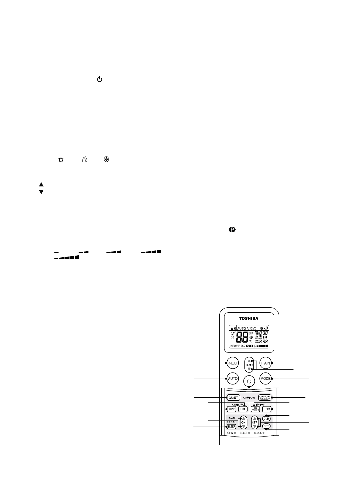
9-6. Remote Controller (RAS-M22NKCV1)
9-6-1. Remote Controller and Its Functions
1 Infrared signal emitter
Transmits a signal to the indoor unit.
2 START/STOP button [ ]
Push the button to start operation.
(A receiving beep is heard.)
Push the button again to stop operation.
(A receiving beep is heard.)
If no receiving sound is heard from the indoor unit,
push the button twice.
3 Mode select button [MODE]
Push this button to select a mode.
Each time you push the button, a mode is selected in
a sequence that goes from A : Auto changeover
control,
A. (A receiving beep is heard.)
: Cool, : Dry, : Fan only and back to
4 Temperature button [TEMP .]
..... The set temperature is increased up to 30°C.
..... The set temperature is droped down to 17°C.
(A receiving beep is heard.)
5 Fan speed button [FAN]
Push this button to select the fan speed.
When you select A UTO, the fan speed is automati-
cally adjusted according to the room temperature.
You can also manually select the desired fan speed
from among five settings.
(LOW
HIGH
, LOW+ , MED , MED+ ,
) (A receiving beep is heard.)
12 Sleep timer button (SLEEP )
Push this button to set the OFF timer .
(1, 3, 5 or 9 hours) (A receiving beep is heard.)
13 High power button (Hi P OWER)
Push this button to start high power operation.
(A receiving beep is heard.)
14 ECO timer button [ECO]
Push this button to start ECO operation.
(A receiving beep is heard.)
15 Quiet button [QUIET]
Push this button to start quiet operation.
(A receiving beep is heard.)
16 Comfort sleep button [COMFORT SLEEP ]
P
ush this button to start the comfort sleep operation. OFF timer is necessary to set together
(1, 3, 5 or 9 hours). (A receiving beep is heard.)
17 P RESET button
Push this button to operate the air conditioner
according to the settings memorized.
(A receiving beep is heard.)
Or push the button for more than 4 seconds to
memorize the setting indicated on the remote
controller and
mark is indicated.
18 Automatic operation button [AUTO]
Push this button to operate the air conditioner
automatically. (A receiving beep is heard.)
6 Auto louver button [SWING]
Push this button to swing the louver.
(A receiving beep is heard.)
Push the button again to stop the louver swinging.
(A receiving beep is heard.)
7 Set louver button [FIX]
Push this button again to adjust the air flow direction.
(A receiving beep is heard.)
8 ON timer button [ON]
Push this button to set the ON timer .
9 OFF timer button [OFF]
Push this button to set the OFF timer .
10 Reserve button [SET]
Push this button to reserve setting of time, ON
timer or OFF timer. (A receiving beep is heard.)
11 Cancel button [CLR]
Push this button to cancel the ON timer and OFF
timer. (A receiving beep is heard.)
18
15
6
12
17
2
7
8
1
5
4
3
16
13
14
11
9
10
– 58 –

9-6-2. Name and Functions of Indications on Remote Controller
[Display]
All indications, except for the clock time indicator, are indicated by pushing the button.
1 Transmission mark
This transmission mark (
remote controller transmits signals to the indoor unit.
) indicates when the
2 Mode display
Indicates the current operation mode.
(AUTO : Automatic control, A : Auto changeover
control,
: Cool, : Dry, : Fan only)
3 Temperature display
Indicates the temperature setting. (17°C to 30°C)
When you set the operating mode to
temperature setting is indicated.
: Fan only, no
4 Louver operation display
Indicates the louver operation. (
: Fix, : Swing)
5 FAN speed display
Indicates the selected fan speed.
AUTO or one of five fan speed levels
(LOW
HIGH
Indicates AUTO when the operating mode is either
AUTO or
, LOW+ , MED , MED+ ,
) can be indicated.
: Dry.
6 TIMER and clock time display
The time set the timer operation or clock time is
indicated.
The preset time is always indicated except for
TIMER operation.
7 Hi P OWER display
Indicates when the Hi POWER operation starts.
Push the [Hi POWER] button to start and push it
again to stop the operation.
8 P RESET display
Flashes for 4 seconds when the [PRESET] button is
pushed and hold to memorize.
mark is indicated when [PRESET] button is
pushed for more than 4 seconds.
Push another button to turn off the mark.
9 ECO display
Indicates when the ECO is in operation.
10 COMFORT SLEEP display
Indicates when the COMFORT SLEEP is in
operation.
Each time you push the [COMFORT SLEEP]
button, the display changes in the sequence of 1, 3,
5 or 9h.
11 QUIET display
Indicates when the QUIET is in operation.
3101 2 8 4
11
79 5 6
• In the illustration, all indications are indicated for
explanation.
During operation, only the relevant indications will
be indicated on the remote controller.
– 59 –

10. INSTALLATION PROCEDURE
10-1. Installation Diagram of Indoor Units
RAS-M10SKCV, RAS-M13SKCV, RAS-M16SKCV
170 mm or more
Hook
Air filter
(Attach to the front panel)
1 Installation plate
Hook
65 mm or more
170
For the rear left and left piping
Wall
Insert the cushion between
the indoor unit and wall, and
tilt the indoor unit for better
operation.
mm or more
Do not allow the drain hose
to get slack.
Cut the piping
hole sloped slightly.
5 Super Oxi
Deo filter
6 Super Sterilizer filter
3 Batteries
8 Pan head
wood screw
2 Wireless remote controller
Before installing the wireless remote controller
• Loading Batteries
1. Remove the battery cover.
2. Insert 2 new batteries (AAA type)
following the (+) and (–) positions.
2 Wireless remote controller
4 Remote controller holder
A
C
L
3 Batteries
Shield pipe
Make sure to run the drain
hose sloped downward.
The auxiliary piping can be
connected to the left, rear left,
rear right, right, bottom right or
bottom left.
Right
Rear right
Bottom
right
Rear left
Bottom left
Left
Insulate the refrigerant pipes separately
with insulation, not together.
8 mm thick heat resisting
polyethylene foam
– 60 –

RAS-M22SKCV
r
t
ook
Hook
g
m
.
t
t
t
.
se
.
cushion betwee
doo
,
p
.
C
t
t
.
3
e
For the rear left and left piping
(Attach to the front panel.)
5 Filter
6 Filter
3 Batteries
2 Wireless
remote controller
Air filter
mm or more
H
8
Pan head
wood screw
Installation plat
Shield pipe
4 Remote controller
holder
Wall
Insert the
unit and wall
better o
Do not allow the drain hose to get slack
Make sure to run the drain ho
sloped downward
The auxiliary piping can be connected
to the left, rear left, rear right, right,
bottom right or bottom left
Righ
Rear righ
Bottom righ
and tilt the indoor unit for
eration
Rea
lef
n the in
ut the
piping hole
sloped slightly.
Lef
Bottom lef
r
Before installing the wireless remote controller
• Loading Batteries
1. Remove the battery cover.
A
C
L
2. Insert 2 new batteries (AAA type)
following the (+) and (–) positions.
2 Wireless remote controller
10-2. Optional Parts, Accessories and Tools
10-2-1. Optional Installation Parts
Part Code
Indoor unit name
Y
RAS-M10SKCV, M13SKCV 6.35 mm 9.52 mm
RAS-M16SKCV, M22SKCV, M22SKCV1 6.35 mm 12.7 mm
Parts name
Refrigerant piping
Insulate the refrigerant pipes separately
with insulation, not together
Batteries
8 mm thick heat resistin
polyethylene foa
Liquid side Gas side
(Outer diameter) (Outer diameter)
Q’ty
1 ea.
Z
Shield pipe (for extension drain hose) (polyethylene foam, 6 mm thick)
1
– 61 –

10-2-2. Accessory and Installation Parts
Part No.
Part name (Q’ty)
Installation plate × 1
ONE-TOUCH
SWNG FIX
QUIET
TIHER
SLEEP
CHK
FILTER CLOCK
SET
Wireless remote controller × 1
PRESET FAN
ON OFF
TEMP
Hi-POWER
COMFORT
MODE
SLEEP
ECO
CLR
Part No.
Part name (Q’ty)
Remote controller holder × 1
Super Oxi Deo filter × 1
Part No.
Part name (Q’ty)
Mounting screw Ø4 × 25L × 6
Remote controller
holder mounting screw
Ø3.1 × 16L × 2
<Others>
Name
Battery × 2
Super Sterilizer filter × 1
Important information and warning
Owner’s manual
Installation manual
This model is not equipped with an extension drain hose.
10-2-3. Installation/Servicing T ools
Changes in the product and components
In the case of an air conditioner using R410A, in order to prevent any other refrigerant from being charged
accidentally, the service port diameter of the outdoor unit control valve (3-way valve) has been changed.
(1/2 UNF 20 threads per inch)
• In order to increase the pressure resisting strength of the refrigerant piping flare processing diameter and size of
opposite side of flare nuts has been changed. (for copper pipes with nominal dimensions 1/2 and 5/8)
New tools for R410A
New tools for R410A
Gauge manifold
Charge hose
Electronic balance
for refrigerant charging
Torque wrench
(nominal diam. 1/2, 5/8)
Flare tool (clutch type)
Gauge for projection
adjustment
Vacuum pump adapter
Gas leakage detector
Applicable to R22 model
×
×
¡
×
¡
——
¡
×
Changes
As pressure is high, it is impossible to measure by means of
conventional gauge. In order to prevent any other refrigerant from
being charged, each port diameter has been changed.
In order to increase pressure resisting strength, hose materials and
port size have been changed (to 1/2 UNF 20 threads per inch).
When purchasing a charge hose, be sure to confirm the port size.
As pressure is high and gasification speed is fast, it is difficult to
read the indicated value by means of charging cylinder, as air
bubbles occur.
The size of opposite sides of flare nuts have been increased.
Incidentally,
a common wrench is used for nominal diameters 1/4 and 3/8.
By increasing the clamp bar’s receiving hole, strength of spring in
the tool has been improved.
Used when flare is made by using conventional flare tool.
Connected to conventional vacuum pump. It is necessary to use
an adapter to prevent vacuum pump oil from flowing back to the
charge hose. The charge hose connecting part has two ports-one
for conventional refrigerant (7/16 UNF 20 threads per inch) and
one for R410A. If the vacuum pump oil (mineral) mixes with R410A
a sludge may occur and damage the equipment.
Exclusive for HFC refrigerant.
• Incidentally, the “refrigerant cylinder” comes with the refrigerant designation (R410A) and protector coating in the
U. S’s ARI specified rose color (ARI color code: PMS 507).
• Also, the “charge port and packing for refrigerant cylinder” require 1/2 UNF 20 threads per inch corresponding to
the charge hose’s port size.
– 62 –

10-3. Indoor Unit
10-3-1. Installation Place
• A place which provides enough spaces around the
indoor unit as shown in the diagram.
• A place where there are no obstacle near the air inlet
and outlet.
• A place which allows easy installation of the piping to
the outdoor unit.
• A place which allows the front panel to be opened.
• The indoor unit shall be installed so that the top of the
indoor unit is positioned at least 2m in height.
• Also, av oid putting an ything on the top of the indoor unit.
Remote controller
• Should be placed where there are no obstacles,
such as curtains, that may block the signal.
• Do not install the remote controller in a place
exposed to direct sunlight or close to a heating
source, such as a stove.
• Keep the remote controller at least 1 m away from
the nearest TV set or stereo equipment.
(This is necessary to prevent image disturbances or
noise interference.)
• The location of the remote controller should be
determined as shown below.
CAUTION
• Direct sunlight on the indoor unit wireless
receiver should be avoided.
• The microprocessor in the indoor unit should not
be too close to r-f sources.
(For details, see the owner's manual.)
10-3-2. Drilling a Hole and Mounting Installation Plate
(Side view)
Reception
range
Indoor unit
Remote
controller
(Top view)
Indoor unit
Reception
range
Fig. 10-3-1
Remote
controller
RAS-M10SKCV, RAS-M13SKCV, RAS-M16SKCV
Drilling a hole
When install the refrigerant pipes from the rear.
Pipe
hole
Ø65 mm
100 mm
Fig. 10-3-2
1. After deter mining the pipe hole position on the
installation plate (
) drill the pipe hole (Ø65 mm)
ð
at a slight downward slant to the outdoor side.
NOTE :
• When drilling into a wall that contains a metal lath,
wire lath or metal plate, be sure to use a pipe hole
brim ring sold separately.
Mounting the installation plate
Anchor bolt holes
62
82.5
1
Installation
plate
170
85
Pipe hole
Indoor unit
Hook
Hook
Thread
Weight
Hook
Pipe hole
7
Mounting screw
RAS-M22SKCV
Drilling a hole
When install the refrigerant pipes from the rear.
35 120 180 240
The center of the pipe hole is the above arrow.
Fig. 10-3-4
1. After determining the pipe hole position on the
installation plate (
) drill the pipe hole (Ø65 mm)
ð
at a slight downward slant to the outdoor side.
NOTE :
• When drilling into a wall that contains a metal
lath, wire lath or metal plate, be sure to use a
pipe hole brim ring sold separately.
Mounting the installation plate
Anchor bolt holes
Hook
ine
l
t
u
o
t
ni
u
o
T
170
2 m or more from floor
Pipe hole
the center of pipe hole
85
Offset 85mm from the left side edge is
Indoor unit
m
0m
24
Hook
l
t
ou
t
i
un
o
T
m
m
35
t
ou
t
i
un
o
T
m
m
0
12
Thread
ine
ne
i
l
0
Weight
3
2
01
2
1
5
3
Mounting
7
screw
e center of pipe hole
Pipe hole
50
e
n
i
l
t
ou
t
i
un
o
T
m
m
0
24
0
4
2
0
8
Hook
m from the right side edge is
23mm
Dia .65mm
40
Offset 23mm from the right side edge is
170
the center of pipe hole
132
23
m
Dia.
65m
Pipe hole
(Dia. 65mm)
Installation
1
plate
2m or more from floor
Fig. 10-3-3
Fig. 10-3-5
– 63 –

When the installation plate is directly
mounted on the wall
1. Securely fit the installation plate onto the wall by
screws with the upper and lower catches, that
hold the indoor unit, facing out.
2. To mount the installation plate on a concrete wall
use anchor bolts. Drill the anchor bolt holes as
illustrated in the figure below.
3. Install the installation plate horizontally and level.
CAUTION
When installing the installation plate with mounting screw, do not use the anchor bolt hole.
Otherwise the unit may fall down and result in
personal injury and property damage.
Anchor bolt
Projection
15mm or less
10-3-3. Electrical Work
1. The supply voltage must be the same as the
rated voltage of the air conditioner.
2. Prepare a power source for the exclusive use of
the air conditioner.
NOTE :
• Wire type : More than 1.5mm²
H07RN-F or 60245 IEC66
CAUTION
• This appliance can be connected to a main
circuit breaker in either of the following two
ways.
1. Connection to fixed wiring:
A switch or circuit breaker which disconnects all poles and has a contact separation of at least 3 mm must be incorporated
in the fixed wiring. An approved circuit
breaker or switch must be used.
2. Connection with power supply plug:
Attach power supply plug with power cord
and plug it into wall outlet. An approved
power supply cord and plug must be used.
Fig. 10-3-6
5 mm dia. hole
7 Mounting screw
Ø4 × 25L
Clip anchor
(local parts)
Fig. 10-3-7
CAUTION
Failure to securely install the unit may result in
personal injury and/or property damage if the
unit falls.
• In case of block, brick, concrete or similar type
walls, drill 5 mm dia. holes in the wall.
• Insert clip anchors for the mounting screws.
NOTE :
• Install the installation plate using mounting
screws between 4 to 6, being sure to secure all
four corners.
NOTE :
• Perform wiring work being sure the wire length is
long enough.
10-3-4. Wiring Connection
How to connect the connecting cable
Wiring the connecting cable can be carried
out without removing the front panel.
1. Remove the air inlet grille.
Open the air inlet grille upward and pull it toward
you.
2. Remove the terminal cover and cord clamp.
3. Insert the connecting cable (or as according to
local regulations/codes) into the pipe hole on the
wall.
4. Pull the connecting cable through the cable slot
on the rear panel so that it protrudes about
15 cm out of the front.
5. Insert the connecting cable fully into the terminal
block and secure it tightly with scre ws.
6. Tightening torque: 1.2 N•m (0.12 kgf•m)
7. Secure the connecting cable with the cord clamp.
8. Attach the terminal cover, rear plate bushing and
air inlet grille on the indoor unit.
– 64 –

CAUTION
10-3-5. Piping and Drain Hose Installation
• Be sure to refer to the wiring system diagram
labeled inside the front panel.
• Check local electrical regulations for any
specific wiring instructions or limitations.
Cord c
T
erminal cover
Scre
lamp
Scre
w
w
Scre
1
2
3
w
Terminal
Earth line
Connecting cab
Fig. 10-3-8
Terminal block
1
2
3
Fig. 10-3-9
b
lock
le
Piping and drain hose forming
• Since condensation results in machine trouble,
make sure to insulate both the connecting pipes
separately.
(Use polyethylene foam as insulating material.)
Rear right
Rear left
Bottom left
Changing
Left
drain hose
Bottom right
Die-cutting
Right
Front panel slit
Fig. 10-3-12
1. Die-cutting front panel slit
Cut out the slit on the left or right side of the front
panel for the left or right connection and the slit
on the bottom left or side of the front panel for
the bottom left or right connection with a pair of
nippers.
2. Changing drain hose
For left connection, left-bottom connection and
rear-left connection’s piping, it is necessary to
relocate the drain hose and drain cap.
Piping preparation
Connecting cable
about 15 cm
Fig. 10-3-10
1
10 m
m
10 mm
10 mm
5
0 mm
Fig. 10-3-11
NOTE :
• WIRE TYPE : More than 1.0mm².
(H07 RN-F or 60245 IEC 66)
Ea
How to remove the drain cap
Clip drain cap with needle-nose pliers, and pull out.
Fig. 10-3-13
r
th
line
How to remove the drain hose
The drain hose is secured in place by a screw.
Remove the screw securing the drain hose, then
pull out the drain hose.
Screw
Drain hose
Fig. 10-3-14
– 65 –

How to attach the drain cap
Left-hand connection with piping
1. Insert hexagonal wrench (4 mm).
4 mm
Fig. 10-3-15
2. Firmly insert drain cap.
No gap
Do not apply lubricating oil
(refrigerant machine oil)
when inserting the drain cap.
If applied, deterioration and
Insert a hexagon
wrench (Ø4mm)
drain leakage of the drain
plug may occur.
Fig. 10-3-16
How to attach the drain hose
Always use the original screw that secured the
drain hose to the unit. If using a different screw
may cause water to leak.
Insert the drain hose firmly until the connector contacts with the insulation, then secure it in place using
the original screw.
Bend the connecting pipes so that they are positioned
within 43 mm above the wall surface.
If the connecting pipes are positioned more than
43 mm above the wall surface, the indoor unit may be
unstable.
When bending the connecting pipe, make sure to use
a spring bender to avoid crushing the pipe.
Refer to the table below for the bending radius
of each connection pipe.
Outer diameter
6.35 mm
9.52 mm
12.7 mm
Bending radius
30 mm
40 mm
50 mm
To connect the pipe after installation of the
unit (figure)
RAS-M10SKCV, RAS-M13SKCV, RAS-M16SKCV
(To the front flare)
270 mm
230 mm
Liquid side
Gas side
Fig. 10-3-19
CAUTION
Securely insert the drain hose and drain cap;
otherwise, water may leak.
In case of right or left piping
• After making slits on the front panel with a knife or
similar tool, cut them out with a pair of nippers or an
equivalent tool.
Slit
Fig. 10-3-17
In case of bottom right or bottom left piping
• After making slits on the front panel with a knife or
similar tool, cut them out with a pair of nippers or an
equivalent tool.
Slit
10-3-18
Fig.
RAS-M22SKCV
(To the front flare)
400 mm
300 mm
Liquid side
Gas side
Fig. 10-3-20
R30 or less (Ø6.35), R40 or less (Ø9. 52), R50 or less (Ø12. 7)
Use polishing (polyethylene core or the like for bending pipe).
43 mm
Outward form of indoor unit
Use a screwdriver handle, etc.
Fig. 10-3-21
NOTE :
If the pipe is incorrectly bent, the indoor unit may be
unstable on the wall.
After passing the connecting pipe through the pipe
hole, connect the connecting pipe to the auxiliary
pipes and wrap the facing tape around them.
– 66 –

CAUTION
50 mm
or more
Do not rise the drain hose.
Do not form the drain hose
into the waved shape.
Do not put the
drain hose end
into water.
Do not put the drain
hose end in the
drainage ditch.
• Bind the auxiliary pipes (two) and connecting
cable with facing tape tightly.
In case of leftward piping and rear-leftward
piping, bind the auxiliary pipes (two) only with
facing tape.
Indoor unit
Auxiliary pipes
Installation
plate
Fig. 10-3-22
•
Carefully arrange the pipes so that none of the
pipes stick out of the rear plate of the indoor unit.
• Carefully connect the auxiliary pipes and
connecting pipes to each other and cut off the
insulating tape wound on the connecting pipe
to avoid doub le-taping at the joint, moreo ver,
seal the joint with the vinyl tape, etc.
• Since condensation can result in machine
performance trouble, be sure to insulate both
connecting pipes. (Use polyethylene foam as
insulating material.)
• When bending a pipe, be careful not to crush it.
Connecting
cable
10-3-7. Drainage
1. Run the drain hose at a downward sloped angle.
NOTE :
• Hole should be made at a slight downward
slant on the outdoor side.
Fig. 10-3-25
2. Put water in the drain pan and make sure that
the water is being drained outside.
3. When connecting extension drain hose, insulate
the connection part of extension drain hose with
shield pipe.
Shield pipe
10-3-6. Indoor Unit Installation
1. Pass the pipe through the hole in the wall, and
hook the indoor unit on the installation plate at
the upper hooks.
2. Swing the indoor unit to right and left to confirm
that it is firmly hooked on the installation plate.
3. While pressing the indoor unit onto the wall,
hook it at the lower part on the installation plate.
Pull the indoor unit toward you to confirm that it is
firmly hooked on the installation plate.
1
2
Hook
• For detaching the indoor unit from the installation
plate pull the indoor unit toward you while pushing
the bottom up at the specified places.
Hook here
1
Installation
plate
Fig. 10-3-23
Push (unhook)
Drain hose
Inside the room
Extension drain hose
Fig. 10-3-26
CAUTION
Install the drain pipe for proper drainage.
Improper drainage can result in water dripping
inside the room.
This air conditioner has been designed to drain
water collected from condensation which forms on
the back of the indoor unit, to the drain pan.
Therefore, do not locate the power cord and other
parts at a high place than the drain guide.
Wall
Drain
guide
PushPush
Fig. 10-3-24
– 67 –
Space for
pipes
Fig. 10-3-27
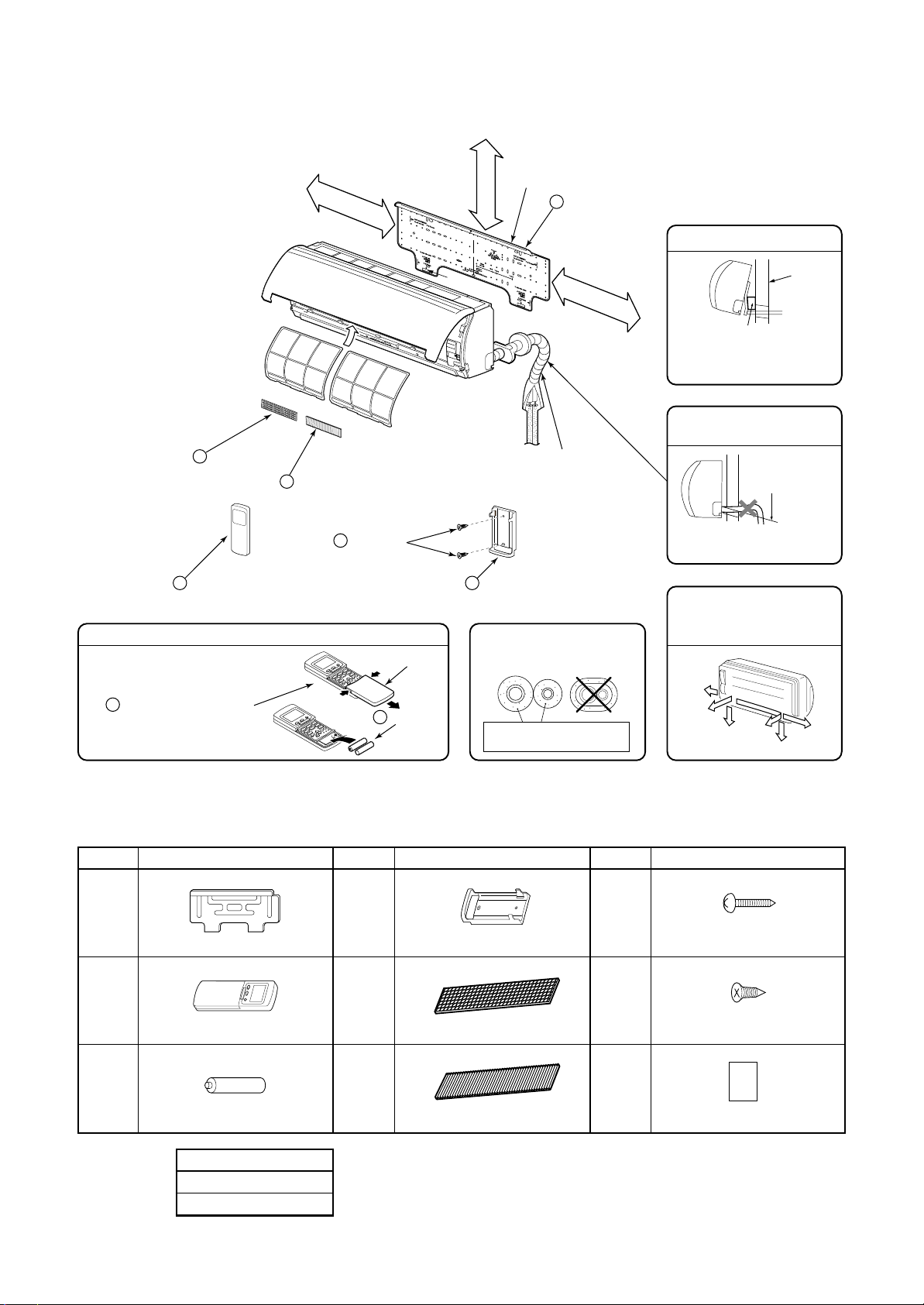
10-4. Installation Diagram of Indoor Unit
RAS-M22NKCV1
(Attach to the front panel)
5 Zeolite Plus
sasa filter
2 Wireless remote controller
Before installing the wireless remote controller
• With the remote controller cover open,
load the batteries supplied correctly,
observing their polarity.
2 Wireless remote controller
6 Bio Ginko filter
170 mm or more
Air filter
8 Pan head
wood screw
3 Batteries
Cover
Hook
2 Installation plate
65 mm or more
Hook
Shield pipe
4 Remote controller holder
Insulate the refrigerant pipes
separately with installation,
not together.
8 mm thick heat resisting
polyethylene foam
170 mm or m
ore
For the rear left and left piping
Wall
Insert the cushion between
the indoor unit and wall, and
tilt the indoor unit for better
operation.
Do not allow the drain hose
to get slack.
Cut the piping
hole sloped slightly.
Make sure to run the drain
hose sloped downward.
The auxiliary piping can be
connected to the left, rear left,
rear right, right, bottom right
or bottom left.
Right
Rear right
Bottom
right
Rear
left
Bottom left
Left
10-4-1. Accessory and Installation Parts
Part No.
<Others>
Part name (Q’ty)
Installation plate × 1
Wireless remote controller × 1
Battery × 2
Name
Owner’s manual
Installation manual
Part No.
Part name (Q’ty)
Remote controller holder × 1
Zeolite plus sasa filter × 1
Bio Gingo filter × 1
– 68 –
Part No.
Part name (Q’ty)
Mounting screw
Ø4 × 25L × 6
Flat head wood screw
Ø3.1 × 16L × 2
B
B label × 1

1. Setting of remote controller selector at the
remote controller side
[B] of the remote controller is displayed with
liquid crystal only when it is set to [B].
There is no display of [A].
• Enter the battery.
• Push the [CHK] button by something with thin
edge. ([00] is displayed.)
• If [MODE] button is pushed while pushing [CHK]
button, the small [B] is displayed at the right of the
setting temperature indication section.
* To reset [A] setting, push the [MODE] button
again while pushing the [CHK] button.
2. Confirm the indoor unit can operate with
the changed setting of the remote controller.
10-4-2. Check and Test Run
1. Check the unit is firmly hooked up on the
installation plate.
2. Check the connecting pipes tightened securely.
Confirm that there is not gas leakage.
3. Confirm that all connecting cables are secured
and correct.
4. Check the pipes insulation.
5. Check the drainage.
6. Connection of the grounding wire.
7. To switch the TEST RUN (COOL) mode, push
[RESET] button for 10 sec.
(The beeper will make a short beep.)
RESET
[MODE] button
[CHK] button
Fig. 10-4-2
8. Operate the unit at cooling operation mode for
15 minutes or more.
Measure the temperature of the intake and
discharge air. Ensure the difference between the
intake temperature and the discharge one is
more than 8°C.
NOTE: Three-minutes protection feature
A protection feature prevents the air condi-
tioner from being activated for about 3 minutes
when it is restarted immediately after operation
or when the power switch is turned on.
9. Explain to the customer on the correct usage of
air conditioner simple layman’s terms.
Fig. 10-4-1
– 69 –

When the installation plate is directly
Earth line
mounted on the wall
1. Securely fit the installation plate onto the wall by
screwing it in the upper and lower parts to hook
up the indoor unit.
2. To mount the installation plate on a concrete wall
with anchor bolts, utilize the anchor bolt holes as
illustrated above.
3. Install the installation plate horizontally in the
wall.
CAUTION
When installing the installation plate with mounting
screw, do not use the anchor bolt hole.
Otherwise the unit may fall down and result in
personal injury and property damage.
Anchor bolt
10-4-3. Electrical Work
1. The supply voltage must be the same as the
rated voltage of the air conditioner.
2. Prepare a power source for exclusive use with
the air conditioner.
NOTE :
• Wire type :
More than 1.5mm² (H07RN-F or 245IEC66)
or 1.3mm² (AWG-16)
CAUTION
• Use power specified above table.
• This appliance can be connected to a mains
in either of the following two ways.
1. Connection to fixed wiring:
A switch or circuit breaker which disconnects all poles and has a contact separation of at least 3 mm must be incorporated
in the fixed wiring. An approved circuit
breaker or switches must be used.
Projection
15mm or less
Fig. 10-4-3
5 mm dia. hole
7 Mounting screw
Ø4 × 25L
Clip anchor
(local parts)
Fig. 10-4-4
CAUTION
Failure to firmly install the unit may result in
personal injury and property damage if the unit
falls.
NOTE :
• Perform wiring work so as to allow a generous
wiring capacity.
10-4-4. Wiring Connection
Air Inlet grille
Front panel
2
Terminal cover
1
Cord clamp
Screw
Terminal block
Earth line
Earth line
• In case of block, brick, concrete or similar type
walls, make 5 mm dia. holes in the wall.
• Insert clip anchors for appropriate mounting
screws.
NOTE :
• Secure four corners and lower parts of the
installation plate with 6 to 8 mounting screws to
install it.
Screw
Connecting cable
Fig. 10-4-5
– 70 –

10-4-4. Installation Place
• A place which provides the spaces around the
indoor unit as shown in the above diagram.
• A place where there is no obstacle near the air
inlet and outlet.
• A place which allows an easy installation of the
piping to the outdoor unit.
• A place which allows the front panel to be
opened.
10-4-5. Cutting a Hole and Mounting
Installation Plate
Cutting a hole
When install the refrigerant pipes from the rear.
CAUTION
• Direct sunlight to the indoor unit wireless
receiver should be avoided.
• The microprocessor in the indoor unit should
not be too close to r-f noise sources.
(For details, see the owner's manual.)
Remote controller
• A place where there are no obstacles such as
curtains, that may block the signal from the indoor
unit.
• Do not install the remote controller in a place
exposed to direct sunlight or close to a heating
source, such as a stove.
• Keep the remote controller at least 1m apart from
the nearest TV set or stereo equipment.
(This is necessary to prevent image disturbances
or noise interference.)
• The location of the remote controller should be
determined as shown below.
180
To pipe hole center
Pipe
100
hole
65m
m
100mm
The center of the pipe
hole is above the arrow.
Fig. 10-4-7
1. After determining the pipe hole position on the
mounting plate (100 mm ð ), drill the pipe hole
(Ø65 mm) at a slight downward slant to the
outdoor side.
NOTE :
• When drilling the wall that contains a metal
lath, wire lath or metal plate, be sure to use a
pipe hole brim ring sold separately.
Mounting the installation plate
For installation of the indoor unit, use the paper
pattern on the back.
(Side view)
Indoor unit
Reception
range
(Top view)
Indoor unit
Remote
controller
*: Axial distance
Fig. 10-4-6
Reception
range
Remote controller
Fig. 10-4-8
– 71 –

How to connect the connecting cable
Slit (rear panel)
Slit
(body-right)
Wiring the connecting cable can be carried
out without removing the front panel.
1. Remove the air inlet grille.
Open the air inlet grille upward and pull it toward
you.
2. Remove the terminal cover and cord clamp.
3. Insert the connecting cable (according to local
cords) into pipe hole on the wall.
4. Take out the connecting cable through the cable
slot on the rear panel so that it is exploded by
about 15 cm long in the front side.
5. Insert the connecting cable fully into the terminal
block and secure it by screw tightly.
6. Tightening torque: 1.2 N•m (0.12 kgf•cm)
7. Secure the connecting cable with the cord
clamp.
8. Fix the terminal cover, rear plate bushing and air
inlet grille on the indoor unit.
1 2 3
NOTE :
Connect the earth line to the metallic part
( mark) located at the side of 3P terminal.
Fig. 10-4-11
How to install the air inlet grille on the
indoor unit.
CAUTION
• Be sure to refer to the wiring system diagram
labeled inside the front panel.
• Check local electrical codes and also any
specific wiring instructions or limitation.
Connecting
cable
about 15cm
Fig. 10-4-9
Stripping length of connecting cable
123
10mm
10mm
• When attaching the air inlet grille, the contrary of
removed operation is performed.
Fig. 10-4-12
10-4-6. Piping and Drain Hose Installation
In case of rightward piping
• After scribing slits of the body-right by a knife or a
marking-off pin, cut them by a pair of nippers or
the like.
40mm
50mm
Earth
line
NOTE :
Use standed wire only.
• WIRE TYPE :
More than 1.5 mm²
(H07 RN-F or 245 IEC 66) or 1.3 mm² (AWG-16)
Fig. 10-4-10
Fig. 10-4-13
– 72 –

In case of downward piping
CAUTION
• After scribing the slit of the body-right by a knife or
a marking-off pin, cut them by a pair of nippers or
the like.
Slit (body-right)
Fig. 10-4-14
Left-hand connection with piping
Bend the connecting pipe so that it is laid within
43 mm above the wall surface.
If the connecting pipe is laid exceeding 43 mm
above the wall surface, the indoor unit may unstably
be set on the wall.
When bending the connecting pipe, make sure to
use spring bender so as not to crush the pipe.
• Bind the auxiliary pipes (two) and connecting
cable with facing tape tightly.
In case of leftward piping and rear-leftward
piping, bind the auxiliary pipes (two) only with
facing tape.
Indoor unit
Auxiliary
pipes
Installation
plate
Connecting
cable
Drain hose
Fig. 10-4-16
•
Carefully arrange pipes so that any pipe does
not stick out of the rear plate of the indoor unit.
• Carefully connect the auxiliary pipes and
connecting pipes to each other and cut off the
insulating tape wound on the connecting pipe
to avoid double-taping at the joint, moreover,
seal the joint with the vinyl tape, etc.
• Since dewing results in a machine trouble,
make sure to insulate both connecting pipes.
(Use polyethylene foam as insulating material.)
•
When bending a pipe, careful do it not to crush it.
Bend the connection pipe within a radius of
30mm.
To connect pipe after installation of unit (figure)
(To the forefront of flare)
400mm
300mm
R 30mm
43mm
80˚
Liquid side
Gas side
Outward form of indoor unit
(Use polyethylene core or
the like for bending pipe.)
Use the handle of screwdriver,etc.
Fig. 10-4-15
10-4-7. Drainage
1. Run the drain hose sloping downwards.
NOTE :
• Hole should be made at a slight downward
slant to the outdoor side.
Do not rise the
drain hose.
50 mm
or more
Do not put the
drain hose end
into water.
Do not form the drain hose
into the waved shape.
Do not put the drain
hose end in the
drainage ditch.
Fig. 10-4-17
2. Put water in the drain pan and make sure that
the water is drained out of doors.
3. When connccting extension drain hose. insulate
the connecting part of extension drain hose with
shield pipe.
NOTE :
If the pipe is bent incorrectly, the indoor unit may
unstably be set on the wall.
After passing the connecting pipe through the pipe
hole, connect the connecting pipe to the auxiliary
pipes and wrap the facing tape around them.
– 73 –
Drain hose
Shield pipe
Inside the room
Fig. 10-4-18
Extension drain hose

CAUTION
Arrange the drain pipe for proper drainage from
the unit.
Improper drainage can result in dew-dropping.
This air conditioner has the structure designed to
drain water collected from dew, which forms on the
back of the indoor unit, to the drain pan.
Therefore, do not store the power cord and other
parts at a height above the drain guide.
Wall
Drain
guide
Space for pipes
Fig. 10-4-19
10-4-9. How to Set Remote Controller
Selector Switch
When two indoor units are installed in the
separated rooms, there is no need to change
the selector switches.
Remote Controller Selector Switch
• When two indoor units are installed in the
same room or the adjacent two rooms, they
may be controlled simultaneously with a single
remote controller.
To prevent this, set either unit and its remote
controller to B setting.(Both units are set to
A setting before shipment).
• The remote controller signal is not received
when the indoor unit setting is different from
the remote controller one.
• The A setting (or B setting) does not relate to
the A room (or B room) in the installation
manual of the outdoor unit.
10-4-8. Indoor Unit Fixing
1. Pass the pipe through the hole in the wall, and
hook the indoor unit on the installation plate at
the upper hooks .
2. Swing the indoor unit to right and left to confirm
that it is firmly hooked up on the installation plate.
3. While pressing the indoor unit onto the wall,
hook it at the lower part on the installation plate.
Pull the indoor unit toward you to confirm that it
is firmly hooked up on the installation plate.
1
2
Hook
• For detaching the indoor unit from the installation
plate pull the indoor unit toward you while pushing
its bottom up at the specified parts.
Hook here
1
Installation
plate
Fig. 10-4-20
Push
(un-hook)
1. Set the remote controller selector switch
with the indoor unit
(For RAS-M22NKCV1)
1) Turn the circuit breaker of the main power switch
off before setting the selector switch.
2) Remove the Air inlet grille and Front panel.
(Refer to Chapter 12-1, procedure , page 109)
3) Open the Electrical part cover (Refer to chapter
12-1, procedure , page 111), then cut the
jumper (J67) with only the nippers for B setting.
CAUTION
Do not use any other sharp tools
(such as cutters, pliers, or the like).
Such tools may cause breakage or damage.
See Fig. 10-4-22.
Push Push
Fig. 10-4-21
Fig. 10-4-22
– 74 –
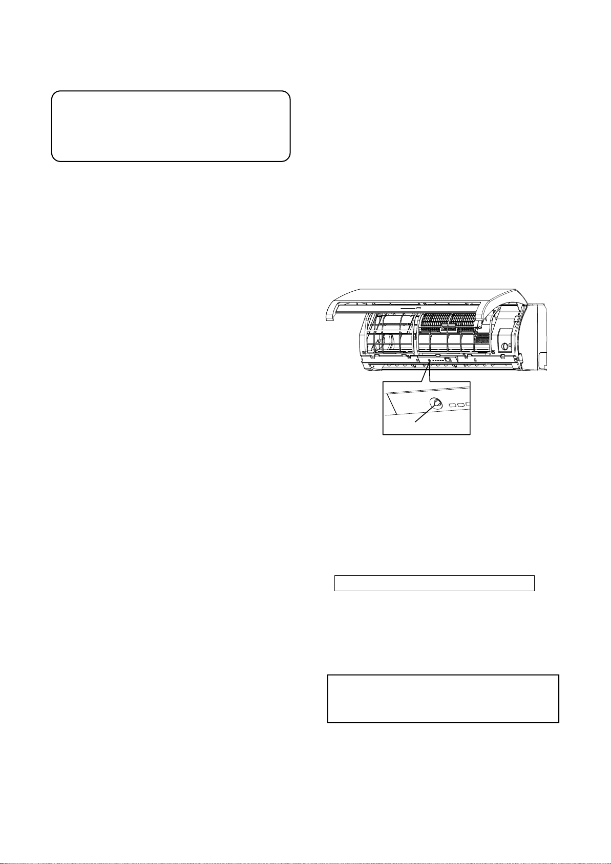
2. Set the remote controller selector switch
with the remote controller
[B] is indicated on the liquid crystal display when
setting remote controller selector switch to B .
[A] is not indicated on the display even if the
selector switch is set to A.
1) Load the remote controller with the batteries.
2) Push the [CHECK] button using something with
sharp point. (The preset temperature on the
remote controller changes to [00].)
3) Push the [MODE] button while pushing the
[CHECK] button, [B] is indicted at the right of the
preset temperature display.
To reset the switch to the [A] setting, push the
[MODE] button again while pushing the [CHECK]
button.
(For remote controller of RAS-M22NKCV1,
see page 46.)
10-4-10. Check and Test Operation
1. Check that the unit is firmly hooked up to the
installation plate.
2. Check that the connecting pipes are tightened
securely.
3. Check that there is no gas leakage.
Check that all connecting cables are connected
securely and properly.
4. Check the insulations for the pipes.
5. Check the drainage.
6. Check the ground wire is connected properly.
7. To switch the operation mode to the TEST RUN
(COOL), turn the switch on and push the
TEMPORARY button for 10 sec.
(The unit beeps shortly.)
TEMPORARY button
Fig. 10-4-23
8. Operate the unit at cooling operation mode for
15 minutes or more.
And take the temperature at the air inlet and
outlet.
Ensure the temperature difference between the
air inlet and outlet is more than 8°C.
NOTE: Three-minutes protection feature
This function feature prevents the unit from being
activated for approximately 3 minutes when it is
restarted immediately after tur ning off or when
the power supply switch is turned off.
9. Check the remote controller operation.
After the test operation check, return the switch to
REMOTE CONTROLLER.
(Push the TEMPORARY button again to return it.)
10. Explain how to use the air conditioner properly
to the customer in professional but simple
terms.
– 75 –

10-5. Which Models can be Combined
Table of models that can be connected
Indoor unit specification
A
10-class
13-class
16-class
22-class
RAS-M22SKCV, RAS-M22NKCV1
High Wall T ype
RAS-M10SKCV
RAS-M13SKCV
RAS-M16SKCV
Combinations of indoor unit (2-room connection)
A
Unit D
Unit C
Unit B
Unit A
12345678910
——————————
——————————
10-class 10-class 10-class 13-class 13-class 16-class 10-class 13-class 16-class 22-class
10-class 13-class 16-class 13-class 16-class 16-class 22-class 22-class 22-class 22-class
Combinations of indoor unit (3-room connection)
A
Unit D
Unit C
Unit B
Unit A
Unit D
Unit C
Unit B
Unit A
12345678910
——————————
10-class 10-class 10-class 10-class 10-class 13-class 10-class 13-class 13-class 16-class
10-class 10-class 10-class 13-class 13-class 13-class 16-class 13-class 16-class 16-class
10-class 13-class 16-class 13-class 16-class 13-class 16-class 16-class 16-class 16-class
11 12 13 14 15
—————
10-class 10-class 13-class 10-class 13-class
10-class 13-class 13-class 16-class 16-class
22-class 22-class 22-class 22-class 22-class
Slim Duct Type
RAS-M10SDCV
RAS-M13SDCV
RAS-M16SDCV
RAS-M22SDCV
Combinations of indoor unit (4-room connection)
A
Unit D
Unit C
Unit B
Unit A
1 2345678910
10-class 10-class 10-class 10-class 10-class 10-class 10-class 13-class 10-class 10-class
10-class 10-class 10-class 10-class 10-class 13-class 13-class 13-class 10-class 10-class
10-class 10-class 10-class 13-class 13-class 13-class 13-class 13-class 16-class 10-class
10-class 13-class 16-class 13-class 16-class 13-class 16-class 13-class 16-class 22-class
Table of models that can be used in combination
A
B
C
D
Total
* The unit A connection port diameter is 6.35/12.7.
* Use a different-diameter joint if the diameters of the connection por t and connection piping are different.
* Mount the different-diameter joint on the connection port of the outdoor unit.
1 unit: 22 or 16 or 13 or 10
1 unit: 22 or 16 or 13 or 10
1 unit: 16 or 13 or 10
1 unit: 13 or 10
52
NOTE
A 1-room connection is not an option for the indoor units (you cannot connect only one indoor unit).
A 2-room or more connection must always be used for the indoor units
(you must connect at least two indoor units).
– 76 –

10-6. Installation of Outdoor Unit
10-6-1. Installation Location
• A place which provides enough space around the
outdoor unit as shown in the diagram.
• A place which can bear the weight of the outdoor
unit and does not allow an increase in noise level
and vibration.
• A place where the operation noise and discharged
air do not disturb neighbors.
• A place which is not exposed to a strong wind.
• A place free of combustible gases.
• A place which does not block a passageway.
• When the outdoor unit is to be installed in an
elevated position, be sure to secure its feet.
• Piping connections to the outdoor unit should be
arranged in the sequence A, then B, C, D, starting
from the bottom. (For each piping connection, the
gas pipe is on the bottom and the liquid pipe on top.)
• When multiple indoor units are to be connected to
the outdoor unit, make sure the ends of the pipes
and wires from each indoor unit are connected to the
outdoor unit correctly. (Problems caused by indoor
units being connected to the outdoor unit incorrectly
are very common in multiple-unit installations.)
• The length and height differences of the connecting
pipes between the indoor and outdoor units must be
within the ranges indicated below.
Table10-6
Allowable piping length and height difference
Piping length
Minimum Maximum Maximum for
for 1 unit for 1 unit total of 4 units
2 m 25 m 70 m ∗1 or 50 m
∗ The outdoor unit should not be installed with one
indoor unit only. Be sure the (outdoor) unit is installed with at least two indoor units.
NOTE:
For installation, at least 3 sides should be kept away
from obstacles (walls).
∗2
Height
difference
15 m
• If the outdoor unit is to be mounted on a wall, make
sure the platform supporting it is sturdy enough.
The platform should be designed and manufactured
to maintain its strength over a long period of time,
and sufficient consideration should be given to
ensuring that the outdoor unit will not fall.
• When the outdoor unit is to be mounted high on a
wall, take particular care to ensure that parts do not
fall, and that the installer is protected.
• When doing installation work at ground level, it is
usual to make wiring and pipe connections to the
indoor units, first, and then to make connections to
the outdoor unit.
However, if outdoor work is difficult it is possible,
instead, to make changes to the procedure.
For example, by making adjustments to the wiring
and piping lengths on the inside (rather than the
outside).
• A place where the drain water does not cause any
problems.
CAUTION
1. Install the outdoor unit in a location where
there are no obstructions near its air intake or
air outlet.
2. When the outdoor unit is installed in a place
that is always exposed to strong winds like on
the coast or on a high story of a building,
secure the normal fan operation using a duct or
a wind shield.
3. Especially in windy areas, install the unit to
prevent the admission of wind.
4. Installation in the following places may result in
trouble. Do not install the unit in such places.
• A place full of machine oil.
• A saline-place such as the coast.
• A place full of sulfide gas.
• A place where high-frequency waves are
likely to be generated, such as from audio
equipment, welders, and medical equipment.
Strong wind
100mm or more
from wall
600mm or more
600mm or more
Fig. 10-6-1
100mm or
more from wall
600m
from
m
w
or m
all
NOTE :
∗1 Indoor unit is connected by either of
RAS-M10SKCV, RAS-M13SKCV, RAS-M16SKCV,
RAS-M22SKCV1.
ore
It does not contain RAS-M22SKCV.
∗2 Indoor unit contain RAS-M22SKCV.
The additional charging of refrigerant is
unnecessary because this conditioner is designed
with charge-less specification.
As shown in the figure, hang power cord
and connecting cable downward.
– 77 –
Fig. 10-6-2

10-6-2. Refrigerant Piping Connection
Flaring
1. Cut the pipe with a pipe cutter.
Tighten the connection
Align the centers of the connecting pipes and
tighten the flare nut as much as possible with your
fingers.
Then tighten the nut with a wrench and torque
wrench as shown in the figure.
90˚
Obliquity Roughness Warp
Fig. 10-6-3
2. Insert a flare nut into the pipe, and flare the pipe.
• Projection margin in flaring:
A (Unit: mm)
Rigid (Clutch type)
Outer diameter
of copper pipe
6.35
9.52
12.7
R410A
tool used
0 to 0.5
0 to 0.5
0 to 0.5
Die
Fig. 10-6-4
Conventional
tool used
1.0 to 1.5
1.0 to 1.5
1.0 to 1.5
Pipe
Imperial (Wing nut type)
Outer diameter of copper pipe
6.35
9.52
12.7
R410A
1.5 to 2.0
1.5 to 2.0
2.0 to 2.5
Half union
Externally
threaded side
Use a wrench to secure.
Use a torque wrench to tighten.
Fig. 10-6-6
CAUTION
• Do not apply excessive force.
Otherwise, the nut may break.
Outer diameter
of copper pipe
6.35 mm
9.52 mm
12.7 mm
14 to 18 (1.4 to 1.8 kgf·m)
33 to 42 (3.3 to 4.2 kgf·m)
50 to 62 (5.0 to 6.2 kgf·m)
Flare nut
Internally
threaded side
Tightening torque
Flare at
indoor unit side
(Unit: N·m)
B
• Flaring size: B (Unit: mm)
Fig. 10-6-5
+0
B
Outer diameter of copper pipe
R410A R22
6.35
9.52
12.7
- 0.4
9.1 9.0
13.2 13.0
16.6 16.2
• In case of flaring for R410A with the conventional
flare tool, pull it out approx. 0.5 mm more than that
of R22 to adjust the specified flare size.
The copper pipe gauge is useful for adjusting
projection margin size.
Flare at
outdoor unit side
Fig. 10-6-7
• Tightening torque for connection of flare pipe
The pressure of R410A is higher than R22.
(Approx. 1.6 times.)
Therefore securely tighten the flare pipes which
connect the outdoor unit and the indoor unit with
the specified tightening torque using a torque
wrench.
If any flare pipe is incorrectly connected, it may
cause not only a gas leakage but also trouble in
the refrigeration cycle.
– 78 –

6.35
D
C
B
A
9.52
6.35
9.52
6.35
9.52
6.35
9.52 or 12.7
UNIT D
UNIT C
UNIT B
UNIT A
Outdoor unit Indoor unit
Fig. 10-6-8
A
B
C
D
Total
1 unit: 22 or 16 or 13 or 10
1 unit: 22 or 16 or 13 or 10
1 unit: 16 or 13 or 10
1 unit: 13 or 10
52
Use a vacuum pump
Be sure to use a vacuum pump with counter-flow
prevention function so that oil inside the pump does
not flow back into the air conditioner pipes when the
pump stops. (If oil inside the vacuum pump enters
the air conditioner circuit which uses R410A, trouble
with the refrigeration system may develop.)
1. Connect the charge hose from the manifold valve
to the service port of the gas side packed v alve.
2. Connect the charge hose to the port of the
vacuum pump.
3. Open fully the low pressure side handle of the
gauge manifold valve.
4. Operate the vacuum pump to begin evacuating.
Perform evacuating for about 35 minutes if the
piping length is 70 meters (assuming a pump
capacity of 27 liters per minute).
Confirm that the compound pressure gauge
reading is –101 kPa (–76 cmHg).
5. Close the low pressure valve handle of gauge
manifold.
6. Open fully the valve stem of the packed valves
(both sides of Gas and Liquid).
7. Remove the charging hose from the service port.
8. Securely tighten the caps on the packed valves.
* The unit A connection port diameter is 6.35/12.7.
* Use a different-diameter joint if the diameters of
the connection port and connection piping are
different.
* Mount the different-diameter joint on the connec-
tion port of the outdoor unit.
A 1-room connection is not an option for the indoor
units (you cannot connect only one indoor unit).
A 2-room or more connection must always be used
for the indoor units (you must connect at least two
indoor units).
All combinations that do not exceed the “Total”
number can be installed.
Note that expanders and reducers may be required
depending on the combination method.
Evacuating
After the piping has been connected to the indoor
unit, perform the air purge.
AIR PURGE
Evacuate the air in the connecting pipes and in
the indoor unit using a vacuum pump.
Do not use the refrigerant in the outdoor unit.
For details, see the vacuum pump manual.
Compound pressure gauge
–101kPa (–76cmHg)
Handle Lo
Charge hose
(For R410A only)
Packed valve
at liquid side
Pressure gauge
Manifold valve
Handle Hi
(Keep full closed)
Charge hose
(For R410A only)
Vacuum pump adapter
for counter-flow prevention
(For R410A only)
Vacuum
pump
Service port
(Valve core (Setting pin))
Packed valve at gas side
Fig. 10-6-9
CAUTION
• IMPORTANT POINTS FOR PIPING WORK
1) Prevent dust and moisture from entering
the pipes.
2) Tighten connections carefully
(between pipes and unit).
3) Evacuate the air in the connecting pipes
using a VACUUM PUMP.
4) Check for gas leaks at all connections.
– 79 –

Packed valve handling precautions
30
30
10
L
N
1012
3
10
10
40
40
Earth line
Connecting
cable
Power cord
Earth line
Terminal block
(Connecting cable)
Screw
Connecting cable
(A unit)
Connecting cable
(C unit)
Power cord
Connecting cable
(B unit)
Connecting cable
(D unit)
• Open the valve stem until it touches the stopper.
Once it is in contact with the stopper, refrain from
applying any more force than is necessary.
• Securely tighten the valve stem cap with torque in
the following table:
Stripping length of connecting cable
Gas side
(12.7 mm)
Gas side
(9.52 mm)
Liquid side
(6.35 mm)
Service port
50 to 62 N·m
(5.0 to 6.2 kgf·m)
33 to 42 N·m
(3.3 to 4.2 kgf·m)
14 to 18 N·m
(1.4 to 1.8 kgf·m)
14 to 18 N·m
(1.4 to 1.8 kgf·m)
Hexagon wrench is required.
4mm
Fig. 10-6-10
Fig. 10-6-11
Fig. 10-6-12
Wiring Connection
1. Remove the side panel and cord clamp from the
outdoor unit.
2. Connect the connecting cable to the terminal as
identified by the matching numbers on the
terminal block of indoor and outdoor unit.
3. Insert the power cord and the connecting cable
fully into the terminal block and secure it tightly
with screws.
4. Use vinyl tape, etc. to insulate the cords which
are not going to be used. Locate them so that
they do not touch any electrical or metal parts.
5. Secure the power cord and the connecting cable
with the cord clamp.
6. Attach the side panel on the outdoor unit.
Power source
Maximum
running current
Installation
fuse rating
Power cord
Connecting cable
H07RN–F or 60245IEC66 (2.5 mm²)
H07RN–F or 60245IEC66 (1.0 mm²)
220–240V ~50Hz
220V ~60Hz
17.1 A
20 A breaker or fuse
(all types can be used)
CAUTION
• Incorrect wiring connection may cause
electrical parts to burn out.
• Be sure to comply with local regulations/codes
when running the wire from outdoor unit to
indoor unit.
(Size of wire and wiring method etc.)
• Every wire must be securely connected.
• If incorrect or incomplete wiring is carried out,
fire or smoke may result.
• Prepare the power supply for the exclusive
use of the air conditioner.
– 80 –

IMPORTANT INSTRUCTION
10-8. Check and T est Run
To all installers
Please be reminded that all air conditioners
installed at HDB flats are subjected to an amp
restriction of 11 A.
It is the installer’s responsibility to have the current
release control set correctly for the type of HDB flat
in which the IMS unit is installed.
The figure below shows how the connector can be
arranged for the appropriate setting.
For further details refer also to the sevice manual.
Maximum current switch connector
11A
Full operation (Delivery)
Mis-wiring (Mis-piping) check connector
(color: red)
Maximum current switch connector
(color: blue)
Open
Short
For R410A, use the leak detector exclusively
manufactured for HFC refrigerant (R410A,
R134a, etc.)
* The conventional leak detector for HCFC
refrigerant (R22, etc.) cannot be used because its
sensitivity for HFC refrigerant lowers to
approx. 1/40 of that manufactured exclusively for
HFC refrigerant.
• Pressure of R410A becomes approx. 1.6 times
that of R22. If installation work has not completely
finished, gas leaks may occur in cases such as
when pressure rises during operation.
• Check the flare nut connections, valve stem cap
connections and service port cap connections for
gas leaks with a leak detector or soap water.
Fig. 10-6-13
10-7. Grounding
This air conditioner must be grounded without fail.
Grounding is necessary not only to safeguard
against the possibility of receiving an electric shock
but also to absorb both the static, which is
generated by high frequencies and held in the
surface of the outdoor unit, and noise since the air
conditioner incorporates a frequency conversion
device (called an inverter) in the outdoor unit.
If the air conditioner is not grounded, users may
receive an electric shock if they touch the surface of
the outdoor unit and that unit is charged with static.
Flare nut connections
(Indoor unit)
• Service port cap
connection
• Valve stem cap
connection
Flare nut connections
(Outdoor unit)
Fig. 10-8-1
CAUTION
• Use a circuit breaker of a type that is not
tripped by shock waves.
• Incorrect/incomplete wiring will cause
electrical fires or smoke.
• Prepare the power source for exclusive use
with the air conditioner.
– 81 –

Mis-wiring (Mis-piping) Check
Make sure that the wiring and piping for each room
have the same alphabetical code (A, B, C, D).
Connect and secure the power cord.
Use the power cord/cables with thickness, type, and
protective devices specified in this manual.
Insulate the unused cords (conductors) with PVC
tape.
1. Turn on the power breaker.
2. Open the side panel of the outdoor unit.
3. Set the indoor unit to COOL mode.
• It is unnecessary to set the temperature.
• Mis-wiring checks cannot be executed when the
outdoor air temperature is 5°C or less.
4. Start the check.
• Disconnect the mis-wiring check connector
(color: Red) from the inverter P.C. board.
5. During checks (Check time 3 to 20 minutes).
• When an error described in the table below
occurrs, check that operation stops and an error
code is displayed on LED.
6. After checks, the check results are displayed on
LED.
• The compressor stops when a mis-wiring
(mis-pipng) error occurrs.
• Confirm the contents of the table below.
• Tur n off the power breaker.
• Correct mis-wiring/mis-piping.
• Connect the mis-wiring check connector.
• Execute the check operation again.
• Automatically return to normal operation when
conditions are normal.
7. Return to normal operation.
• To retur n to normal operation during check
operation or after a mis-wiring (mis-piping) error
has been determined, connect the mis-wiring
check connector.
Mis-wiring (mis-piping) check by LED Indication
• For this outdoor unit, self-mis-wiring (mis-piping) checks are possible using the five LEDs (1 Yellow + 4 Red).
* LEDs (D800 to D804) are provided on the inverter P.C. board.
LED
During check
Check results
D800 D801 D802 D803 D804
lllll
¥¥
¥
¥
¥
¥
¥
¥
¥
¥
¥
¥
¥
¥
¥
¥
¥
¥
¥
¥
lll
¥
l
ll
lll
¤
l
ll
lll
¤¤
¤
¤
l
l
ll
¤¤¤
¤¤
¤
l
ll
¥
l
¥
lll
ll
¤
l
¤
¤
ll
l
ll
¤¤
¤
¤
l
l
¤
l
¤
¤¤
l
l
¤
l
¤¤
¤¤¤
¤¤¤¤
Description
Normal operation (no error)
Checking A unit
Checking B unit
Checking C unit
Checking D unit
Crush/Clog of Pipe A
Crush/Clog of Pipe B
Crush/Clog of Pipe C
Crush/Clog of Pipe D
Mis-wiring/Mis-piping or Crush/Clog of Pipe A, B
Mis-wiring/Mis-piping or Crush/Clog of Pipe A, C
Mis-wiring/Mis-piping or Crush/Clog of Pipe A, D
Mis-wiring/Mis-piping or Crush/Clog of Pipe B, C
Mis-wiring/Mis-piping or Crush/Clog of Pipe B, D
Mis-wiring/Mis-piping or Crush/Clog of Pipe C, D
A, B, C Mis-wiring/Mis-piping
A, B, D Mis-wiring/Mis-piping
A, C, D Mis-wiring/Mis-piping
B, C, D Mis-wiring/Mis-piping
A, B, C, D Mis-wiring/Mis-piping
Pack ed valve stays closed
D800 D801D802D803 D804
Yellow
Mis-wiring (Mis-piping)
Check connector
(Color:RED)
Check mode
Normal operation
Fig. 10-8-2
LED
Red
Short Open
Short
LED : Light Emitting Diode, : ¤ LED ON, l: LED OFF, ¥: LED Flash
– 82 –

10-9. Useful Functions
Red
Yellow
D800 D801 D802D803 D804
LED
Self-Diagnosis by LED Indication
• For this outdoor unit, by referr ing to the 5 LED (1 Yellow + 4 Red) indicator lights, self-diagnosis is possible.
• LEDs (D800 to D804) are located on the sub-control board underneath the inverter.
Contents
Normal running
IGBT short circuit, Compressor motor rear short
Trouble on position detecting circuit
Trouble on current detecting circuit
Discharge pipe temperature sensor (TD) fault
Trouble on outdoor fan
Outdoor temperature sensor (TO) fault
Trouble on compressor system
Gas side pipe temperature sensor a (TGa) fault
Gas side pipe temperature sensor b (TGb) fault
Gas side pipe temperature sensor c (TGc) fault
Gas side pipe temperature sensor d (TGd) fault
Gas leakage, PMV fault, Sensor fault
Indoor evaporator pipe sensor (TC) out of place , PMV fault, Sensor fault
Indoor or outdoor mis-wiring, Gas leakage, TC sensor out of place,
PMV fault, Sensor fault
Communication trouble between MCU
Compressor lock
Trouble on discharge temperature, Gas leakage
Compressor break down
Indoor
alarm code
None
14
16
17
19
1A
1B
1C
1C
1C
1C
1C
1C
1C
1C
1C
1D
1E
1F
LED indication
D800 D801 D802 D803 D804
lllll
l
¤¤
ll
l
¤¤¤
lll
¤
¤¤¤¤
¤
¤¤
llll
l
¤¤¤
lll
¤¤
¤
l
¤¤
lll
¤
lll
ll
¤
¤¤
ll
ll
¤
l
lll
¤¤
ll
¤
ll
l
l
¤¤
l
¤¤
ll
¤
l
l
¤
¤
¤
l
l
¤
¤
¤
¤
¤
l
l
l
• These LEDs do not normally light.
1. If trouble occurs, LED goes on according to the contents of trouble
as shown in the table above.
2. When two or more troubles occur, LEDs go on cyclically (alternately).
3. When the trouble is eliminated, LEDs go off.
¤ : LED ON, l : LED OFF
Fig. 10-9-1
– 83 –

11. HOW TO DIAGNOSE THE PROBLEM
11-1. First Confirmation
11-1-1. Confirmation of Power Supply
Confirm that the power breaker operates (ON) normally.
11-1-2. Confirmation of Power Voltage
Confirm that power voltage is AC 220–240 ±10%.
If power voltage is not in this range, the unit may not operate nor mally.
11-1-3. Operation Which is not a Trouble (Program Operation)
For controlling the air conditioner, the program operations are built in the microcomputer as described in the
following table.
If a claim is made for running operation, check whether or not it meets to the contents in the following table.
When it does, we inform you that it is not trouble of equipment, but it is indispensable for controlling and
maintaining of air conditioner.
Table 11-1-1
No.
1
When power breaker is turned “ON”, the
operation lamp (Green) of the indoor unit
flashes.
2
Compressor may not operate even if the
room temperature is within range of
compressor-ON.
3
In DRY and ECO mode, FAN (air flow)
display does not change even though FAN
(air flow select) button is operated.
4
Increasing of compressor motor speed stops
approx. 30 seconds after operation started,
and then compressor motor speed increases
again approx. 30 seconds after.
Operation of air conditioner
Description
The OPERATION lamp of the indoor unit flashes when
power source is turned on.
If [START/STOP] button is operated once, flashing
stops. (Flashes also in power failure)
The compressor does not operate while compressor
restart delay timer (3 minutes timer) operates.
The same phenomenon is found after power source has
been turned on because 3 minutes timer operates.
The air flow indication is fixed to [AUTO].
For smooth operation of the compressor, the
compressor motor speed is restricted to Max. 41 rps
for 2 minutes, and Max. 91 rps for 2 minutes to
3 minutes, respectively after the operation has started.
– 84 –

11-2. Primary Judgment
Indoor indication
lamp flashes.
Which lamp
does flash?
To diagnose the troubles, use the following methods.
1) Judgment by flashing LED of indoor unit
2) Self-diagnosis by service check remote controller
3) Judgment of trouble by every symptom
Firstly use the method 1) for diagnosis. Then, use the method 2) or 3) to diagnose the details of troubles.
11-3. Judgment by Flashing LED of Indoor Unit
While the indoor unit monitors the operation status of the air conditioner, if the protective circuit operates, the
contents of self-diagnosis are displayed with block on the indoor unit indication section.
Table 11-3-1
Item
A
B
C
D
E
Check code
——
Block display
OPERATION (Green)
Flashing display (1 Hz)
OPERATION (Green)
Flashing display (5 Hz)
OPERATION (Green)
TIMER (Yellow)
Flashing display (5 Hz)
OPERATION (Green)
FILTER (Orange)
Flashing display (5 Hz)
OPERATION (Green)
TIMER (Yellow)
FILTER (Orange)
Flashing display (5 Hz)
Description for self-diagnosis
Power failure (when power is ON)
Protective circuit operation for indoor P.C. board
Protective circuit operation for connecting cable
and serial signal system
Protective circuit operation for outdoor P.C. board
Protective circuit operation for others
(including compressor)
NOTES :
1. The contents of items B and C and a part of item E are displayed when air conditioner operates.
2. When item B and C, and item B and a part of item E occur concurrently, priority is given to the block of item B.
3. The check codes can be confirmed on the remote controller for servicing.
– 85 –

11-4. Self-Diagnosis by Remote Controller (Check Code)
1. If the lamps are indicated as shown B to E in Table 11-4-1, e xecute the self-diagnosis by the remote controller.
2. When the remote controller is set to the service mode, the indoor controller diagnoses the operation
condition and indicates the information of the self-diagnosis on the display of the remote controller with the
check codes.
If a fault is detected, all lamps on the indoor unit will flash at 5Hz and it will beep for 10 seconds
(Beep, Beep, Beep ... ). The timer lamp usually flashes (5Hz) during self-diagnosis.
11-4-1. How to Use Remote Controller in Service Mode
[RAS-M10SKCV, RAS-M13SKCV, RAS-M16SKCV, RAS-M22SKCV]
1
Push [CHECK] button with a tip of pencil to set the
remote controller to the service mode.
• “ ” is indicated on the display of the remote controller.
PRESET
ONE-TOUCH
QUIET
SWING
TIMER
SLEEP
CHK
TOSHIBA
FAN
TEMP
TEMP
MODE
COMFORT
PURE
FIX Hi-POWER ECO
ON
FILTER
SLEEP
OFF
CLOCK
Push [ON ] or [OFF ] button
2
If there is no fault with a code, the indoor unit will beep
once (Beep) and the display of the remote controller will
change as follows :
• • •
• The TIMER indicator of the indoor unit flashes continuously.
(5 times per 1 sec.)
• Check the unit with all 52 check codes ( to )
as shown in Table-11-4-1.
• Push [ON ] or [OFF ] button to change the check code
backward.
CLR
If there is a fault, the indoor unit will beep for 10 seconds
SET
(Beep, Beep, Beep ... ).
Note the check code on the display of the remote controller.
• 2-digits alphanumeric will be indicated on the display.
• All indicators on the indoor unit will flash.
(5 times per 1 sec.)
Alphanumeric characters are
used for the check codes.
is 5. is 6.
is A. is B.
is C. is D.
Push [CLR] button.
3
After service finish for clear service code in memory .
• "7F" is indicated on the display of the remote controller.
Push [START/STOP] button to release the service mode.
4
• The display of the remote controller returns to as it was
before service mode was engaged.
Fig. 11-4-1
– 86 –

[RAS-M22NKCV1]
1
Push [CHK] button with a tip of pencil to set the
remote controller to the service mode.
• “ ” is indicated on the display of the remote controller.
• The timer lamp on the indoor unit flashes continuously.
(5 times per 1 sec.)
Push [TIMER ] button.
2
If there is no fault with a code, the indoor unit will beep once (Pi)
and the display of the remote controller will change as follows:
• • •
• Check the unit with all 35 check codes (00 to 22) as shown
in Table 11-4-1.
• Push [TIMER ] button to change the check code backwards.
• Alphanumeric characters are
used for the check code.
is 5. is 6.
is A. is B.
is C. is D.
If there is a fault, the indoor unit will beep for 10 seconds
(Beep, Beep, Beep...).
Note the check code on the display of the remote controller.
• 2-digits alphanumeric will be indicated on the display.
• All lamps on the indoor unit will flash. (5 times per 1 sec.)
Push [CLR] button.
3
After service finish for clear service code in memory .
• “7F” is indicated on the display of the remote controller.
4
Push [ ] button to release the service mode.
• The display of the remote controller returns to as it was
before service mode was engaged.
Fig. 11-4-2
– 87 –

11-4-2. Caution at Servicing
1. After servicing, push the START/STOP button to return to the normal mode.
2. After servicing by the check code, turn off breaker of the power supply, and turn on breaker of the power
supply again so that memory in the microcomputer returns the initial status.
Howe ver, the check codes are not deleted even if the power supply is turned off because they are stored in
the fixed memory.
3. After servicing, push [CLR] button under check mode status and then send the check code “7F” to the
indoor unit. The error code stored in memory is cleared.
Table 11-4-1
Block distinction
Check
code
Indoor P.C.
board etc.
Not
displayed
Connecting
cable and
serial signal
Block
Check
code
Operation of diagnosis function
Cause of operation
Short-circuit or disconnection of the room
temperature sensor
(TA sensor).
Being out of place,
disconnection, shortcircuit, or migration of
heat exchanger sensor
(TC sensor)
Being out of place,
disconnection, shortcircuit, or migration of
heat exchanger sensor
(TCJ sensor)
Lock of indoor fan or
trouble on the indoor fan
circuit
Trouble on other indoor
P.C. boards
Return serial signal is not
sent to indoor side from
operation started.
1) Defective wiring of
connecting cable
2) Operation of compressor thermo
Gas shortage
Gas leak
Air
conditioner
status
Operation
continues.
Operation
continues.
Operation
continues.
All off
Operation
continues.
Operation
continues.
Remarks
Displayed when
error is detected.
Displayed when
error is detected.
Displayed when
error is detected.
Displayed when
error is detected.
Displayed when
error is detected.
Flashes when
trouble is detected
on Return serial
signal, and normal
status when signal
is reset.
Judgment and action
1. Check the room temp. sensor.
2. When the room temp. sensor is
normal, check P.C. board.
1. Check heat exchanger sensor.
2. When heat exchanger sensor is
normal, check P.C. board.
1. Check heat exchanger sensor.
2. When heat exchanger sensor is
normal, check P.C. board.
1. Check the motor.
2. When the motor is normal, check
P.C. board.
Replace P.C. board.
1. When the outdoor unit never
operate:
1) Check connecting cable, and
correct if defective wiring.
2) Check 25A fuse of inverter
P.C. board.
3) Check 3.15A of inverter P.C.
board.
2. To display [Other] block during
operation, check compressor
thermo. operation and supply
gas (check gas leak also).
3. Unit operates normally during
check.
If return serial signal does not
stop between indoor terminal
board 2 and 3, replace inverter
P.C. board.
If signal stops between indoor
terminal board 2 and 3, replace
indoor P.C. board.
– 88 –

Block distinction
Check
code
Block
Outdoor P.C.
board
Not
displayed
Outdoor P.C.
board
Others
(including
compressor)
Check
code
Operation of diagnosis function
Cause of operation
Inverter over-current
protective circuit
operates. (Short time)
Position-detect circuit
error or short-circuit
between windings of
compressor
Current-detect circuit
error
Being out of place,
disconnection or shortcircuit of the outdoor
heat exchanger sensor
(TE) or suction temp.
sensor (Ts)
Disconnection or shortcircuit of discharge
temp. sensor
Outdoor fan drive
system error
Outdoor heat exchanger
temp. sensor error
Compressor drive output
error, Compressor error
(lock, missing, etc.),
Break down
Return serial signal has
been sent when
operation started, but it
is not sent from halfway.
1) Compressor thermo.
operation
Gas shortage
Gas leak
2) Instantaneous power
failure
Compressor does not
rotate.
(Current protective
circuit does not operate
when a specified time
passed after compressor
had been activated.)
Discharge temp.
exceeded 117°C
Break down of
compressor
Air
conditioner
status
All off
All off
All off
All off
All off
All off
Operation
continues
All off
Operation
continues
All off
All off
All off
Remarks
Displayed when
error is detected.
Displayed when
error is detected.
Displayed when
error is detected.
Displayed when
error is detected.
Displayed when
error is detected.
Displayed when
error is detected.
——
Displayed when
error is detected.
Flashes when
trouble is detected
on return serial
signal, and normal
status when signal
is reset.
Displayed when
error is detected.
Displayed when
error is detected.
Displayed when
error is detected.
Judgment and action
Even if trying operation again, all
operations stop immediately. :
Replace P.C. board.
1. Even if connecting lead wire of
compressor is removed,
position-detect circuit error
occurred. : Replace P.C. board.
2. Measure resistance between
wires of compressor, and
perform short-circuit. :
Replace compressor.
Even if trying operation again, all
operations stop immediately. :
Replace P.C. board.
1. Check sensors (TE, TS).
2. Check P.C. board.
1. Check discharge temp. sensor
(TD).
2. Check P.C. board
Position-detect error, over-current
protective operation of outdoor fan
drive system, fan lock, etc. :
Replace P.C. board or fan motor.
1. Check outdoor temp. sensor
(TO).
2. Check P.C. board.
Check 5-serial LED of outdoor unit.
When 20 seconds passed after
start-up, position-detect circuit error
occurred. : Replace compressor.
Trouble on PMV.
1. Repeat Start and Stop with
interval of approx. 10 to 40
minutes. (Code is not displayed
during operation.)
Supply gas.
(Check also gas leak).
2. Unit operates normally dur ing
check.
If return serial signal does not
stop between indoor terminal
block 2 and 3, replace inverter
P.C. board.
If signal stops between indoor
terminal block 2 and 3, replace
indoor P.C. board.
1. Trouble on compressor
2. Trouble on wiring of compressor
(Missed phase)
1. Check dischage temp. sensor
(TD).
2. Gas leakage
3. Trouble on PMV.
1. Check power voltage.
(220–230–240 V +10%)
2. Overload operation of refrigeration cycle
Check installation condition
(Short-circuit of outdoor diffuser).
– 89 –

11-5. Judgment of Trouble by Every Symptom
11-5-1. Indoor Unit (Including Remote Controller)
(1) Power is not turned on (Does not operate entirely)
<Primary check>
1. Is the supply voltage normal?
2. Is the normal voltage provided to the outdoor unit?
3. Is the crossover cable connected properly?
4. Is the fuse (F01) blown?
RAS-M10SKCV, RAS-M13SKCV
Turn off power supply once, and
5 second later, turn it on again.
Operation
Check Item
Considerable principle cause
Measures
NO
Is OPERATION indicator flashing?
on power supply by pushing
Is fuse (F01) of indoor
control board blown?
NO
Is voltage (DC12V or 5V)
indicated on rear of indoor
control board normal?
YES
Is it possible to turn
[START/STOP] button
on remote controller?
YES
Unit operates normally.
YES
YES
(C01, C02, C03, R01, R02,
D01, D02, D03, D04 and T01)
NO
Parts
are defective.
Does transmission mark
on remote controller flash
normally and is its signal
transmitted properly?
YES
Item by symptoms
NO
Remote controller is defective.
Refer to
“(5) Troubleshooting for remote controller”.
Microcomputer
is defective.
NO
Parts of a power supply
circuit defective.
Replace main
P.C. board
• Be sure to disconnect the motor connector CN31 after shut off the power supply, or it will be a cause of
damage of the motor.
– 90 –

RAS-M16SKCV, RAS-M22SKCV
Turn off power supply once, and
5 second later, turn it on again.
Operation
Check Item
Considerable principle cause
Measures
NO
Is OPERATION indicator flashing?
on power supply by pushing
Is fuse (F01) of indoor
control board blown?
NO
Is voltage (DC12V or 5V)
indicated on rear of indoor
control board normal?
NO
YES
Is it possible to turn
[START/STOP] button
on remote controller?
YES
Unit operates normally.
YES
YES
Parts (R04, R05, DB01,
C01, C03, IC01 and T01)
NO
are defective.
Does transmission mark
on remote controller flash
normally, and is its signal
transmitted properly?
YES
connector between
Item by symptoms
NO
Remote controller is defective.
Refer to
“(5) Troubleshooting for remote controller”.
Does fan motor
CN10 1 – 3
short-circuit?
NO
Microcomputer
is defective.
YES
Is DC310–340V supplied
between CN10 1 – 3 ?
YES
NO
Parts of a power supply
circuit are defective.
Replace main
P.C. board
Replace fan motor.
• Be sure to disconnect the motor connector CN31 after shut off the power supply, or it will be a cause of
damage of the motor.
– 91 –

RAS-M22NKCV1
NO
to turn on power supply
by pushing [ ] button
Unit operates normally.
Is fuse (F01) of indoor
control board blown?
NO
Turn off
power supply once
and 5 second later,
turn it on again.
Is OPERATION
lamp flashing?
YES
Is it possible
on remote controller?
YES
on remote controller flash
normally, and is its signal
YES
Parts
(R04, C01, DB01, C50,
IC08, IC11 and T01)
are defective.
NO
Does transmission mark
transmitted properly?
YES
NO
Refer to
“(5) Troubleshooting for Remote Controller.”
Does fan motor
connector between
1 and 3 short-circuit?
NO
Operation
Check Item
Considerable principle cause
Measures
Item by symptoms
Remote controller is defective.
YES
Is voltage (DC 12V or 5V)
indicated on rear of indoor
control board normal?
NO
Is the voltage
14 to 31.4V DC at C50?
YES
this problem is one step short
of power P.C. board block.
Are DC 5V,
DC 12V supplied to
main P.C. board?
YES
Turn off breaker once
and turn it on again after
YES
NO
Refer to
<Primary check> or
NO
removing motor.
Microcomputer
is defective.
Are DC 5V or
DC 12V supplied to
main P.C. board?
YES
NO
Replace motor
Replace
main P.C. board.
Regulator
IC (IC08, IC11)
are defective.
• Be sure to disconnect the motor connector CN10 after shut off the power supply, or it will be a cause of
damage of the motor.
– 92 –

(2) Power is not turned on though Indoor P.C. board is replaced
<Confirmation procedure>
Turn on power supply.
Does OPERATION lamp flash?
YES
NO NO
Is wired correctly to white and
black lead wires of terminal block?
YES
Correct wiring.
To item of
Power supply is not turned on .
– 93 –

(3) Only the indoor motor fan does not operate
<Primary check>
1. Is it possible to detect the power supply voltage (AC220–240V) between and on the terminal block?
2. Does the indoor fan motor operate in cooling operation?
(In heating operation, the indoor fan motor does not operate for approximately 10 minutes after it is turned
on, to prevent a cold air from blowing in.)
RAS-M10SKCV, RAS-M13SKCV
Turn off power supply once
and turn it on again.
Does fan motor continue
to operate?
NO
Start to operate
indoor unit in cooling operation
at airflow level “LOW”.
Does indoor fan operate?
YES
Change airflow level to “HIGH”.
YES
Control P.C. board failure.
Dose AC120V or
lighter voltage apply to between red
and black lead of the motor?
YES
Turn OFF the power.
Is it possible to rotate
cross-flow fan by hand properly?
YES
Turn OFF the power.
NONO
Replace main P.C. board.
NO
Replace bearing.
Is it possible to change
airflow level to “HIGH”?
YES
NO
Stop the operation.
by hand at the operation stop condition,
detected between 2 (Purple lead) and
3 (Blue lead) of the motor connector
When rotating the cross-flow fan
is the rotation signal (DC + 12V 0V)
(CN33) (1 pulse / 1 revolution).
YES
Motor circuit (D301, IC31, Q301)
12V power circuit (T101) failure.
– 94 –
NO
Replace the fan motor.
Replace the P.C. board.Fan motor operates normally.
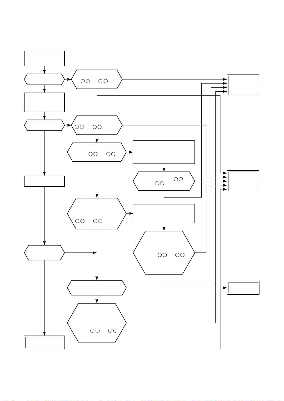
RAS-M16SKCV, RAS-M22SKCV
Turn off power
supply once, and
turn it on again.
Does fan motor
continue to operate?
NO
Start to operate
indoor unit in cooling
operation at airflow
level “LOW”.
Does indoor
fan operate?
YES
Change airflow level
to “HIGH”.
Is it possible to
change airflow level
to “HIGH”?
YES
YES
Is it possible to detect
DC 1V or more between
5 + and 3 – of
motor connector (CN31).
YES
Is it possible to detect
NO
DC 310–340V between
1 + and 3 – of motor
connector (CN31).
YES
(Motor connection condition)
Is it possible to detect DC 15V
between 4 + and 3 – of
motor connector (CN31).
YES
Start to operate the
indoor unit in except
heating operation.
At this time, is it possible to
detect DC 1V or more between
5
+ and 3 – of motor
connector (CN31)?
YES
NO
Is it possible to
rotate cross-flow fan by
hand properly?
YES
NO
NO
Turn off indoor unit and remove
connector from motor.
NO
Then push START/STOP button
on remote controller to stop
flashing lamp on indoor unit.
Is it possible to detect
DC 15V between 4 +
and 3 – of motor
connector (CN31).
Turn off indoor unit and
NO
remove connector from motor.
Then start to operate indoor
unit with remote controller.
Start to operate the
indoor unit in except
heating operation.
At this time, is it possible
to detect DC 1V or more
between
of motor connector (CN31)?
within 15 seconds after
5
+ and 3 –
(Check this condition
starting unit.)
NO
YES
YES
NO
NO
Replace indoor
fan motor.
Replace main
P.C. board.
Replace
bearing.
Fan motor
operates normally.
Turn off indoor unit
and rotate cross-flow
fan by hand when the
unit is on standby.
At this time, is it possible to
detect DC 1V or more
between 5 + and 3 –
of motor connector
(CN31).
YES
NO
– 95 –

RAS-M22NKCV1
<Check procedure>
Shut off the
power supply once.
Turn the power supply.
Does the fan stop in
no operating status?
YES
Start the operation
with low fan setting
in cool operation.
Does the fan rotate?
YES
Change the setting
of cooling to high fan.
NO
Does AC 120 V or
higher voltage apply to
between red and black lead
of fan motor?
YES
Shut off the power supply.
Does the cross flow
fan rotate normally?
YES
Turn on the power supply.
Control P.C. board is defective.
supply cord connect completely?
NO
Repair the
bearing of the fan.
Does connecting terminal,
connecting cable or power
Is not found the short wire
about connecting cable
and power cord?
YES
Thermal fuse operated due to
prevent temperature rising cause
of incompleted connecting.
Motor control circuit failure
(IC05, D38) or 12 V
power circuit failure (IC08).
Replace the P.C. board.
NONONO
NO
Does the fan speed
become higher?
YES
of the motor connector (CN11) when rotating the
Normal Replace the control P.C. board.
Operation
stops.
Is the rotation signal
(DC +5 V – 0 V) output between 2
(gray lead wire) and 3 (brown lead wire)
cross flow fan by hand in no operating status?
(1 pulse/one turn)
YES
– 96 –
Replace the P.C. board.
NO
Replace
the fan motor.
Replace the cable connecting
(or power cord), thermal fuse
and terminal block.

(4) Indoor fan motor automatically starts to rotate by turning on power supply
(For DC fan motor in RAS-M16SKCV, RAS-M22SKCV)
<Cause>
The IC is built in the indoor fan motor.
Therefore the P.C. board is also mounted to inside of the motor.
If the P.C. board is soldered imperfectly or the IC is defective, the fan motor may automatically rotate by turning
on power supply.
<Inspection procedure>
1. Remove the front panel. (Remove 2 screws.)
2. Remove the cover of the fan motor lead wires.
3. Check DC voltage with CN31 connector while the fan motor is rotating.
NOTE :
• Do not disconnect the connector while the fan motor is rotating.
• Use a thin test rod.
Indoor fan starts rotating when power supply is turned on.
P.C. board
(Check output DC voltage of fan motor on P.C. board.)
Measure voltage between 3 (GND : BLACK)
and 5 (V line : YELLOW) of motor connector (CN31)
while indoor fan motor is rotating.
DC 1.0V or more
P.C. board is defective.
Replace P.C. board. Replace motor.
Under DC 1.0V
Motor is defective.
Yellow
Black
DC
CN31
6 (Blue)
5 (Yellow)
4 (White)
3 (Black)
2 –
1 (Red)
– 97 –

(For AC fan motor in RAS-M10SKCV, RAS-M13SKCV)
<Inspection procedure>
1. Remove the front panel. (Remove 2 screws.)
2. Remove the cover of the fan motor lead wires.
3. Check AC voltage with CN31 connector while the fan motor is rotating.
NOTE :
• Using a tester, measure the resistance value of each winding coil.
• Use a thin test rod.
AFS-220-20-4AR
• Do not disconnect the connector while the fan motor is rotating.
• For P.C. board side, proceed to the item “Only indoor fan does not operate” of “Judgment of Trouble by Every
Symptom” (Refer to Section 11-5-1, (3) Page-94).
WHI
5
CN31
3
1
BLK
RED
BLK
WHI
RED
BLK
3
3
WHI
2
2
RED
1
1
CN33
P.C. board
BLU
3
PUR
2
GRY
1
BLU
PUR
GRY
3
2
1
Position (P.C. board)
Between S (Black) – Q (Red)
Between S (Black) – U (White)
Between Q (Red) – U (White)
BLU
3
PUR
2
GRY
1
Resistance value
74 ± 15 Ω
100 ± 20 Ω
174 ± 35 Ω
– 98 –

(5) Troubleshooting for remote controller
<Primary check>
Check that A or B selected on the main unit is matched with A or B selected on the remote controller.
Is receiver
on indoor unit
exposed to
direct sunlight?
YES
NO
Is there any
thyristor
fluorescent light
nearby?
YES
NO
Push the START/STOP button.
Is transmission
mark indicated?
YES
Does indoor unit
NO
operate when moving
remote controller
near receiver or
indoor unit?
YES
Batteries are
exhausted.
The unit does not beep at all.
Operation lamp on indoor
unit is not indicated.
NO
Push RESET button
on remote controller
with tip of pencil.
Avoid direct
sunlight.
NO
Keep indoor unit
away from thyristor
fluorescent light.
Does indoor unit
start to operate by
automatic restart
function?
YES
Is radio sound affected
by remote controller
when a signal is transmitted
at distance of 5 cm
from radio?
YES
P.C. board
is defective.
Replace
P.C. board.
NO
NO
Replace
batteries.
Push the START/
STOP button
Is transmission
mark indicated?
YES
Does indoor unit
beep and operate?
YES
Normal
operation
NO
Remote controller
is defective.
Replace
remote controller.
NOTE : After replacing batteries,
push the RESET button
with a tip of a pencil.
– 99 –

11-5-2. Wiring Failure (Interconnecting and Serial Signal Wire)
(1) Outdoor unit does not operate
1) Is the voltage between and of the indoor terminal block varied?
Confirm that transmission from indoor unit to outdoor unit is correctly performed based upon the
following diagram.
NOTE:
• Measurement should be performed 2 minutes and 30 seconds after starting of the operation.
• Be sure to prepare a diode for judgment.
Terminal block at indoor side
Red
White
3
2
Terminal block
1
S5277G
S5277G or equivalent (G or J type)
(Diode with rated voltage of 400V
or more is acceptable.)
Tester
Normal time : Voltage swings between DC15 and 60V. ..................Inverter Assembly check (11-7-1.)
Abnormal time : Voltage does not vary.
(2) Outdoor unit stops in a little while after operation started
<Check procedure> Select phenomena described below.
1) The outdoor unit stops 10 to 20 minutes after operation started, and 10 minutes or more are required to
restart the unit.
Gas circulation amount is down.
Measure gas pressure.
Thermo. operation of compressor
Gas shortage
Gas leak
Pipe clogging
2) If the unit stops once, it does not operate until the power will be turned on again.
To item of Outdoor unit does not operate.
3) The outdoor unit stops 10 minutes to 1 hour after operation started, and an alarm is displayed.
(Discharge temp. error check code 03, 1E Sensor temp. error check code 02, 1C)
Gas leak
PMV is defective.
Mis-wiring of connecting wires of indoor/outdoor units
Clogging of pipe and coming-off of TC sensor
Refer to the
service manual of the outdoor unit.
– 100 –
 Loading...