

Toshiba RAS-13UKHP-E2, RAS-13UAH-E2, RAS-10UKHP-E2, RAS-10UAH-E2, RAS-13UKP-E2 Service Manual
...
FILE NO. SVM-03004(1)
SERVICE MANUAL
AIR CONDITIONER
SPLIT WALL TYPE
July, 2003
RAS-13UKHP-E2 / RAS-13UAH-E2
RAS-10UKHP-E2 / RAS-10UAH-E2
RAS-13UKP-E2 / RAS-13UA-E2
RAS-10UKP-E2 / RAS-10UA-E2
RAS-13UKPX2 / RAS-13UAX2
RAS-10UKPX2 / RAS-10UAX2

– 1 –
FILE NO. SVM-03004(1)
CONTENTS
1. SPECIFICATIONS
2. CONSTRUCTION VIEWS
2-1 Indoor Unit
2-2 Outdoor Unit
3. WIRING DIAGRAM
3-1 RAS-13UKHP-E2 / RAS-13UAH-E2
3-2 RAS-10UKHP-E2 / RAS-10UAH-E2
3-3 RAS-13UKP-E2 / RAS-13UA-E2
RAS-10UKP-E2 / RAS-10UA-E2
RAS-13UKPX2 / RAS-13UAX2
RAS-10UKPX2 / RAS-10UAX2
4. SPECIFICATION OF ELECTRICAL PARTS
4-1 Indoor Unit (RAS-13UKHP-E2, RAS-10UKHP-E2)
4-2 Outdoor Unit (RAS-13UAH-E2)
4-3 Outdoor Unit (RAS-10UAH-E2)
4-4 Indoor Unit (RAS-13UKP-E2, RAS-10UKP-E2, RAS-13UKPX2, RAS-10UKPX2)
4-5 Outdoor Unit (RAS-13UA-E2)
4-6 Outdoor Unit (RAS-13UAX2)
4-7 Outdoor Unit (RAS-10UA-E2)
5. REFRIGERATION CYCLE DIAGRAM
5-1 RAS-13UKHP-E2 / RAS-13UAH-E2
5-2 RAS-10UKHP-E2 / RAS-10UAH-E2
5-3 RAS-13UKP-E2 / RAS-13UA-E2
5-4 RAS-10UKP-E2 / RAS-10UA-E2
5-5 RAS-13UKPX2 / RAS-13UAX2
5-6 RAS-10UKPX2 / RAS-10UAX2
6. CONTROL BLOCK DIAGRAM
6-1 RAS-13UKHP-E2 / RAS-13UAH-E2, RAS-10UKHP-E2 / RAS-10UAH-E2
6-2 RAS-13UKP-E2 / RAS-13UA-E2, RAS-10UKP-E2 / RAS-10UA-E2
RAS-13UKPX2 / RAS-13UAX2 , RAS-10UKPX2 / RAS-10UAX2
7. OPERATION DESCRIPTION
7-1 Outline of Air Conditioner Control
7-2 Description of Operation Circuit
7-3 Hi POWER Mode
7-4 High-Temperature Limit Control
7-5 Low-Temperature Limit Control
7-6 Defrost Operation
7-7 Current Limit Control
7-8 Auto Restart Function
7-9 Filter Check Lamp

– 2 –
FILE NO. SVM-03004(1)
8. INSTALLATION PROCEDURE
8-1 Safety Cautions
8-2 Installation Diagram of Indoor and Outdoor Units
8-3 Installation
8-4 Indoor Unit
8-5 Outdoor Unit
8-6 How to Set Remote Control Selector Switch
8-7 Others
9. TROUBLESHOOTING CHART
9-1 Troubleshooting Procedure
9-2 Basic Check Items
9-3 Primary Judgement
9-4 Self-Diagnosis by Remote Control (Check Code)
9-5 Troubleshooting Flowcharts
9-6 Troubleshooting for Remote Control
10. PART REPLACEMENT
10-1 Indoor Unit
10-2 Outdoor Unit
11. EXPLODED VIEWS AND PARTS LIST
11-1 Indoor Unit (E-Parts Assy)
11-2 Indoor Unit
11-3 Outdoor Unit (RAS-13UAH-E2)
11-4 Outdoor Unit (RAS-10UAH-E2)
11-5 Outdoor Unit (RAS-13UA-E2)
11-6 Outdoor Unit (RAS-10UA-E2)
11-7 Outdoor Unit (RAS-13UAX2)
11-8 Outdoor Unit (RAS-10UAX2)

– 3 –
FILE NO. SVM-03004(1)
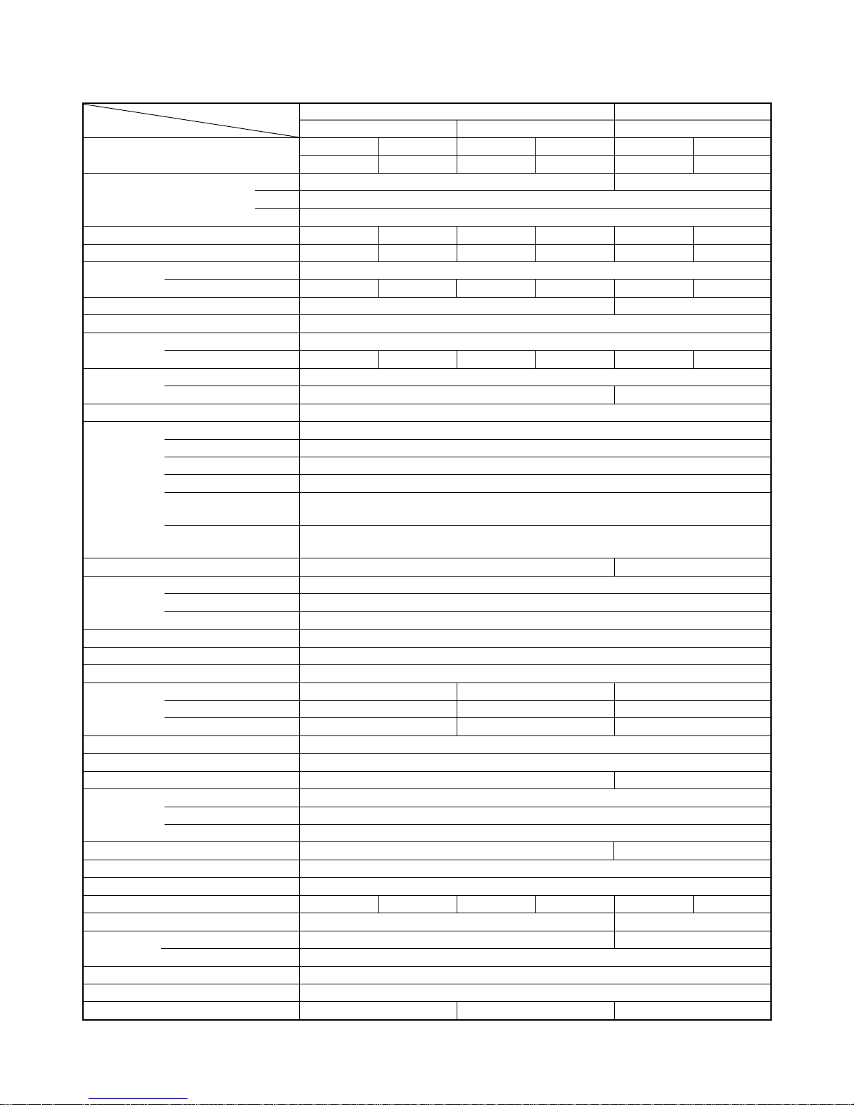
MODEL RAS-13UKHP-E2 / RAS-13UAH-E2 RAS-13UKP-E2 / RAS-13UA-E2
ITEM Cooling Heating Cooling
Capacity
220 V 240 V 220 V 240 V 220 V 240 V
kW 3.55 3.60 4.40 4.45 3.70 3.75
Phase 1∅
Power source V 220 – 240
Hz 50
Pow er consumption kW 1.27 1.32 1.26 1.33 1.24 1.28
Pow er factor % 98 96 98 96 98 95
Running Indoor A 0.15
current Outdoor A 5.75 5.60 5.70 5.65 5.75 5.60
Starting current A 25 24
Moisture removal lit/h 2.0
Noise
Indoor (H/M/L) dB 41/35/31
Outdoor (220 – 240 V)dB 49 51 49 51 47 48
Refrigerant
Name of refrigerant R22
Rated amount kg 1.00 0.80
Refrigerant control Capillary tube
Gas side size mm ∅12.7
Connection type Flare connection
Liquid side size mm ∅6.35
Interconnection
Connection type Flare connection
pipe
Maximum length
m15*
1
(One way)
Maximum height
m6
difference
INDOOR UNIT RAS-13UKHP-E2 RAS-13UKP-E2
Height mm 275
Dimensions Width mm 790
Depth mm 208
Net weight kg 10
Evaporator type Finned tube
Indoor fan type Cross flow fan
High fan m3/h 630 650 630
Air volume Medium fan m3/h 520 550 520
Low fan m3/h 430 490 430
Fan motor output W 20
Air filter Honeycomb woven filter with PP frame
OUTDOOR UNIT RAS-13UAH-E2 RAS-13UA-E2
Height mm 550
Dimensions Width mm 780
Depth mm 270
Net weight kg 37 35
Condenser type Finned tube
Outdoor fan type Propeller fan
Airflow volume m3/h 2120 2200 2120 2200 2120 2200
Fan motor output W 42
Compressor
Model PH170T2-4L2 PH160T2-4LH2
Output W 1100
Safety device Fuse, Overload relay
Louver type Automatic louver
Usable outdoor temperature range °C 15 ~ 43 –10 ~ 24 15 ~ 43
1. SPECIFICATIONS
– 4 –
FILE NO. SVM-03004(1)
MODEL RAS-10UKHP-E2 / RAS-10UAH-E2 RAS-10UKP-E2 / RAS-10UA-E2
ITEM Cooling Heating Cooling
Capacity
220 V 240 V 220 V 240 V 220 V 240 V
kW 2.70 2.75 3.12 3.15 2.65 2.70
Phase 1∅
Power source V 220 – 240
Hz 50
Power consumption kW 1.00 1.05 0.89 0.91 0.80 0.85
Power factor % 95 92 94 91 96 94
Running Indoor A 0.15
current Outdoor A 4.65 4.60 4.15 4.00 3.65 3.60
Starting current A 19 16
Moisture removal lit/h 1.2
Noise
Indoor (H/M/L) dB 39/33/26
Outdoor (220 – 240 V)dB 47 49 47 49 44 45
Refrigerant
Name of refrigerant R22
Rated amount kg 0.76 0.68
Refrigerant control Capillary tube
Gas side size mm ∅9.52
Connection type Flare connection
Liquid side size mm ∅6.35
Interconnection
Connection type Flare connection
pipe
Maximum length
m 10*
1
(One way)
Maximum height
m5
difference
INDOOR UNIT RAS-10UKHP-E2 RAS-10UKP-E2
Height mm 275
Dimensions Width mm 790
Depth mm 208
Net weight kg 10
Evaporator type Finned tube
Indoor fan type Cross flow fan
High fan m3/h 570 610 630
Air volume Medium fan m3/h 460 520 490
Low fan m3/h 340 400 370
Fan motor output W 20
Air filter Honeycomb woven filter with PP frame
OUTDOOR UNIT RAS-10UAH-E2 RAS-10UA-E2
Height mm 550
Dimensions Width mm 780
Depth mm 270
Net weight kg 31 30
Condenser type Finned tube
Outdoor fan type Propeller fan
Airflow volume m3/h 2030 2150 2030 2150 1740 1850
Fan motor output W 18 20
Compressor
Model PH120T1-4C 2PS146D5AB02
Output W 750
Safety device Fuse, Overload relay
Louver type Automatic louver
Usable outdoor temperature range °C 15 ~ 43 –10 ~ 24 15 ~ 43
– 5 –
FILE NO. SVM-03004(1)
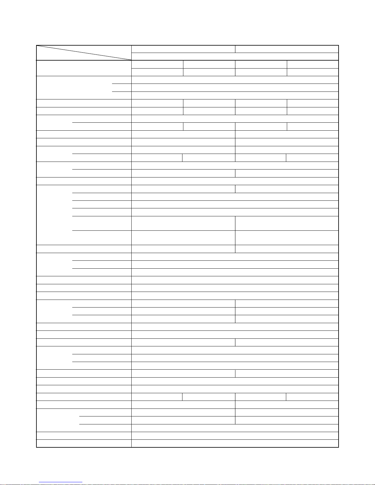
MODEL
RAS-13UKPX2 / RAS-13UAX2 RAS-10UKPX2 / RAS-10UAX2
ITEM Cooling
Capacity
220 V 240 V 220 V 240 V
kW 3.70 3.75 2.65 2.70
Phase 1∅
Power source V 220 – 240
Hz 50
Pow er consumption kW 1.24 1.28 0.80 0.85
Pow er factor % 98 95 97 95
Running Indoor A 0.15
current Outdoor A 5.60 5.45 3.60 3.58
Starting current A 24 16
Moisture removal lit/h 2.0 1.2
Noise
Indoor (H/M/L) dB 41/35/31 39/33/26
Outdoor dB 47 48 44 45
Refrigerant
Name of refrigerant R22
Rated amount kg 0.80 0.65
Refrigerant control Capillary tube
Gas side size mm ∅12.70 ∅9.52
Connection type Flare connection
Liquid side size mm ∅6.35
Interconnection
Connection type Flare connection
pipe
Maximum length
m 15*
1
10*
1
(One way)
Maximum height
m6 5
difference
INDOOR UNIT RAS-13UKPX2 RAS-10UKPX2
Height mm 275
Dimensions Width mm 790
Depth mm 208
Net weight kg 10
Evaporator type Finned tube
Indoor fan type Cross flow fan
High fan m3/h 630 630
Air volume Medium fan m3/h 550 490
Low fan m3/h 460 370
Fan motor output W 20
Air filter Honeycomb woven filter with PP frame
OUTDOOR UNIT RAS-13UAX2 RAS-10UAX2
Height mm 550
Dimensions Width mm 780
Depth mm 270
Net weight kg 35 30
Condenser type Finned tube
Outdoor fan type Propeller fan
Airflow volume m3/h 2030 2150 1740 1850
Fan motor output W 30 20
Compressor
Model PH160T2-4LH2 PH102T1-4CH
Output W 1100 750
Safety device Fuse, Overload relay
Louver type Automatic louver
Usable outdoor temperature range °C 21 ~ 43
– 6 –
FILE NO. SVM-03004(1)
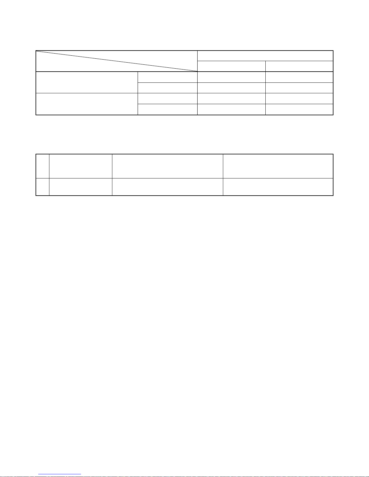
Note : 1
• Capacity is based on the following temperature conditions.
Note : 2
• Charge refrigerant according to the table below.
RAS-13UKHP-E2 / RAS-13UAH-E2 RAS-10UKHP-E2 / RAS-10UAH-E2
Refrigerant RAS-13UKP-E2 / RAS-13UA-E2 RAS-10UKP-E2 / RAS-10UA-E2
Refrigerant RAS-13UKPX2 / RAS-13UAX2 RAS-10UKPX2 / RAS-10UAX2
*1 No need to charge
15 m or less 10 m or less
extra refrigerant
Temperature
Condition
JIS C9612-1994
Cooling Heating
Indoor unit inlet air temperature
(DB) 27°C20°C
(WB) 19°C15°C
Outdoor unit inlet air temperature
(DB) 35°C7°C
(WB) 24°C6°C
– 7 –
FILE NO. SVM-03004(1)
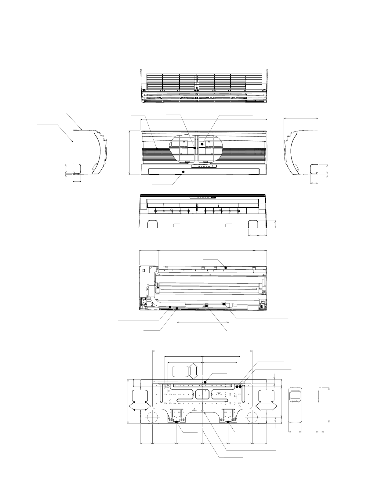
2. CONSTRUCTION VIEWS
2-1. Indoor Unit
Knock out system
Back body
Front panel
Air outlet
Air inlet
Air filter
Heat exchanger
Knock out system
660
275
790
208
48
48
48
26
4519040
32
64
590
320
620
235 235
215 215
9090
275
45
150150 160160
120 80
53
660
Hanger
Hanger
Hanger
Hanger
Hanger
Drain hose (0.54 m)
Connecting pipe (0.43 m)
(Flare ∅6.35)
For stud bolt
(∅8~∅10)
For stud bolt (∅6)
Installation plate outline
Center line
Minimum
distance
to ceiling
1
7
0
o
r m
o
re
Minimum
distance
to ceiling
1
7
0
o
r m
o
re
6
5
o
r m
o
re
Minimum
distance
to ceiling
Wireless remote control
57 18
160
(For 13 series ; Flare ∅12.7
For 10 series ; Flare ∅9.52)
Connecting pipe (0.33 m)

– 8 –
FILE NO. SVM-03004(1)
2-2.Outdoor Unit
310
310
302
102
310
302
302
530
265
600
A Detail Drawing (Back Leg)
A
B Detail Drawing (Front Leg)
52
R15
32.5
115 125
R5.5
∅30 Drain outlet
FAN GUARD
36
∅6 Hole
2-∅11 x 14 Hole
(For ∅8-∅10 anchor bolt)
∅436
4 x ∅11 Long holes (For ∅8-∅10 anchor bolt)
∅11 x 14 Hole
∅6 Hole
36
52
310
330
R15
270
600 90
780 62
COVER PV
Electrical
part cover
Liquid side
(Flare ∅6.35)
Gas side
(Flare ∅9.52)
10 Series
Gas side
(Flare ∅12.7)
13 Series
Service port
600 or more
13 Series
A 600 mm 400 mm
B 100 mm 45 mm
10 Series
B or more
A or more
100 or more
325
600
Air inlet
Air outlet
Installation dimension
120
75
54
B
Z
ZView
– 9 –
FILE NO. SVM-03004(1)
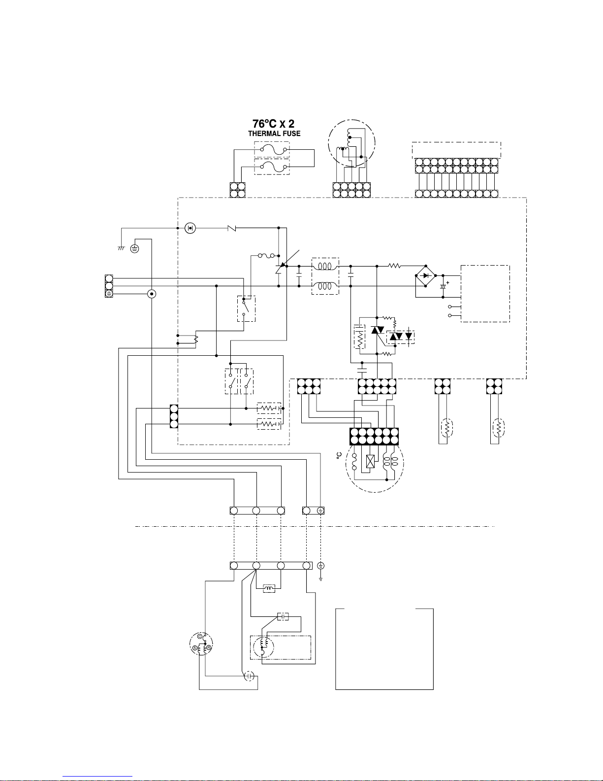
3. WIRING DIAGRAM
3-1.RAS-13UKHP-E2 / RAS-13UAH-E2
BLU
BLU
BLU
BLU
BLU
BLU
BLU
BLU
BLU
BLU
WHI
YEL
CN25
CN13
CN07
BLK
GRN&YEL
POWER
TERMINAL
BLOCK
CHASSIS
POWER SUPPLY
SINGLE PHASE
220 − 240 V~,
50 Hz
BRW
BLU
GRN&YEL
BLK
RY03
BLK
RED
RED
RED
CAPACITOR
WHI BLK
SOLENOID COIL
BLU
CAPACITOR
FAN
MOTOR
PNK
WHI
COMPRESSOR
RY04
YEL
BLK
WHI
RED
BLU
GRN&YEL
135
GRY
BRW
BLK
WHI
RED
CR01
CR02
CN27
INDOOR
TERMINAL
BLOCK
OUTDOOR
TERMINAL
BLOCK
WHI
T02
C.T
DSA
VARISTOR
RY01
4
3
F01
C15
L01
IC03
C58
R48
CN01CN03
THERMO
SENSOR
(TA)
HEAT
EXCHANGER
SENSOR
(TC)
CN10
R46
CR03
D38
C01 R01
DB01
POWER
SUPPLY
CIRCUIT
C02
DC 12V
DC 5V
R21
VARISTOR
MAIN P.C. BOARD
MCC-862
T6.3A
250V
P04
SG01
CN04
R22
PNK
PNK
YEL
YEL
YEL
WHI
INFRARED RAYS RECEIVE
AND INDICATION PARTS
CN11
AC FAN MOTOR
INDOOR
OUTDOOR
BLK
BLK
1
35
1
35
24
24
6
6
4 5 6 7 8 9
10 11
3
1
2
3
3
2
1
1
4
4
4 5 6 7 8 9
10 11
3
1
2
4 5 6 7 8 9
10 11
3
1
2
2 1
3
5
4
2 1
3
5
4
1
2
1
2
N
L
1
3
5
1
3
5
1
2
1
2
3
3
112
2
BLK
BLK
112
2
1
3
:
:
:
:
:
:
:
:
:
:
:
BROWN
RED
WHITE
YELLOW
BLUE
BLACK
GRAY
PINK
ORANGE
GREEN &
GREENGRN
YELLOW
BRW
RED
WHI
YEL
BLU
BLK
GRY
PNK
ORN
GRN&YEL
COLOR IDENTIFICATION
R47
Louver motor
(L)2(N)
BLU
– 10 –
FILE NO. SVM-03004(1)
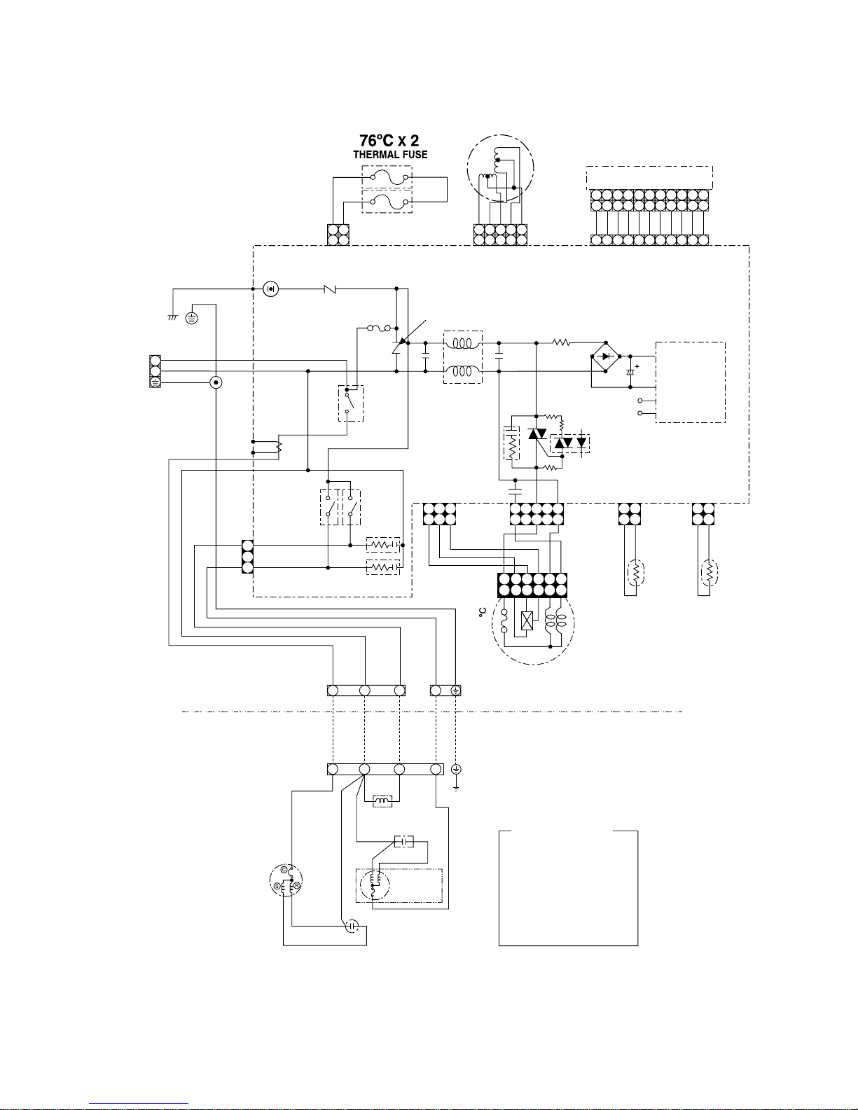
3-2.RAS-10UKHP-E2 / RAS-10UAH-E2
BLU
BLU
BLU
BLU
BLU
BLU
BLU
BLU
BLU
BLU
WHI
YEL
CN25
CN13
CN07
BLK
GRN&YEL
POWER
TERMINAL
BLOCK
POWER SUPPLY
SINGLE PHASE
220 − 240 V~,
50 Hz
BRW
BLU
GRN&YEL
BLK
RY03
RY04
YEL
BLK
WHI
RED
BLU
GRN&YEL
135
GRY
BRW
BLK
WHI
RED
CR01
CR02
CN27
INDOOR
TERMINAL
BLOCK
WHI
T02
C.T
DSA
VARISTOR
RY01
4
3
F01
C15
L01
IC03
C58
R48
CN01CN03
THERMO
SENSOR
(TA)
HEAT
EXCHANGER
SENSOR
(TC)
CN10
R46
CR03
D38
C01 R01
DB01
POWER
SUPPLY
CIRCUIT
C02
DC 12V
DC 5V
R21
VARISTOR
MAIN P.C. BOARD
MCC-862
T6.3A
250V
P04
SG01
CN04
R22
PNK
PNK
YEL
YEL
YEL
WHI
INFRARED RAYS RECEIVE
AND INDICATION PARTS
CN11
AC FAN MOTOR
INDOOR
OUTDOOR
BLK
BLK
1
35
1
35
24
24
6
6
4 5 6 7 8 9
10 11
3
1
2
3
2
1 4
4 5 6 7 8 9
10 11
3
1
2
4 5 6 7 8 9
10 11
3
1
2
2 1
3
5
4
2 1
3
5
4
1
2
1
2
N
L
1
3
5
1
3
5
1
2
1
2
3
3
112
2
BLK
BLK
112
2
1
3
:
:
:
:
:
:
:
:
:
:
:
BROWN
RED
WHITE
YELLOW
BLUE
BLACK
GRAY
PINK
ORANGE
GREEN &
GREENGRN
YELLOW
BRW
RED
WHI
YEL
BLU
BLK
GRY
PNK
ORN
GRN&YEL
COLOR IDENTIFICATION
R47
Louver motor
CHASSIS
BLK
RED
RED
RED
CAPACITOR
WHI BLK
SOLENOID COIL
BLK
CAPACITOR
FAN
MOTOR
PNK
WHI
COMPRESSOR
OUTDOOR
TERMINAL
BLOCK
3
1
4
(L)2(N)
BLK
– 11 –
FILE NO. SVM-03004(1)
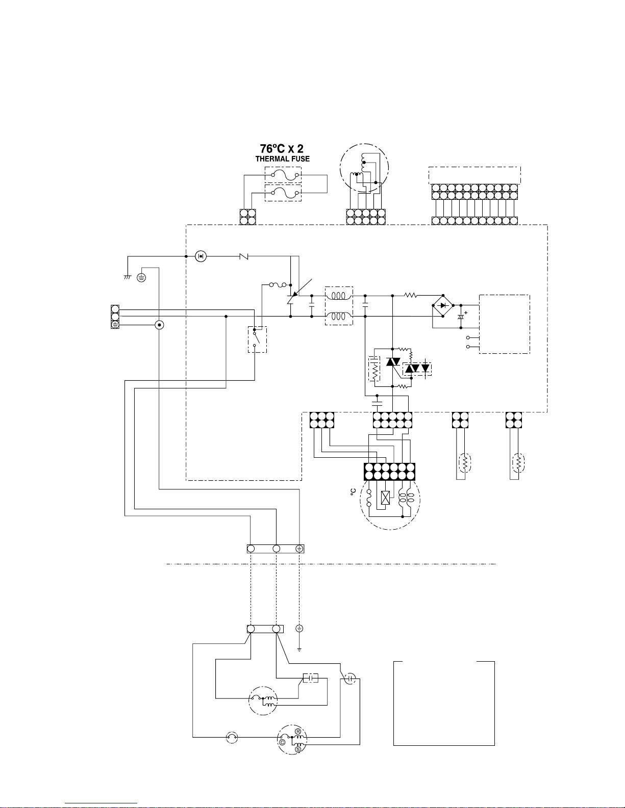
3-3.RAS-13UKP-E2 / RAS-13UA-E2
RAS-10UKP-E2 / RAS-10UA-E2
RAS-13UKPX2 / RAS-13UAX2
RAS-10UKPX2 / RAS-10UAX2
CN13
CN07
BLK
GRN&YEL
POWER
TERMINAL
BLOCK
POWER SUPPLY
SINGLE PHASE
220 − 240 V~,
50 Hz
BRW
BLU
BLK
WHI
GRN&YEL
INDOOR
TERMINAL
BLOCK
OUTDOOR
TERMINAL
BLOCK
WHI
DSA
VARISTOR
RY01
4
3
F01
C15
L01
IC03
C58
R48
R46
R47
CR03
D38
C01 R01
DB01
POWER
SUPPLY
CIRCUIT
C02
DC 12V
DC 5V
R21
VARISTOR
MAIN P.C. BOARD
MCC-862
T6.3A
250V
P04
SG01
CN04
INDOOR
OUTDOOR
1 2
YEL
135
GRY
BRW
BLK
WHI
RED
CN01CN03
THERMO
SENSOR
(TA)
HEAT
EXCHANGER
SENSOR
(TC)
CN10CN11
AC FAN MOTOR
BLK
BLK
1
35
1
35
24
24
6
6
1
3
5
1
3
5
1
2
1
2
3
3
112
2
BLK
BLK
112
2
:
:
:
:
:
:
:
:
:
:
:
BROWN
RED
WHITE
YELLOW
BLUE
BLACK
GRAY
PINK
ORANGE
GREEN &
GREENGRN
YELLOW
BRW
RED
WHI
YEL
BLU
BLK
GRY
PNK
ORN
GRN&YEL
COLOR IDENTIFICATION
BLU
BLU
BLU
BLU
BLU
BLU
BLU
BLU
BLU
BLU
WHI
YEL
CN25
PNK
PNK
YEL
YEL
YEL
WHI
INFRARED RAYS RECEIVE
AND INDICATION PARTS
4 5 6 7 8 9
10 11
3
1
2
4 5 6 7 8 9
10 11
3
1
2
4 5 6 7 8 9
10 11
3
1
2
2 1
3
5
4
2 1
3
5
4
1
2
1
2
R22
N
L
Louver motor
GRN&YEL
1
(L)
2
(N)
COMPRESSOR
FAN MOTOR
CAPACITOR
CAPACITOR
CHASSIS
RED
RED
RED
PNK
WHI
WHI
BLK BLK
OVERLOAD RELAY
BLK
– 12 –
FILE NO. SVM-03004(1)
4. SPECIFICATION OF ELECTRICAL PARTS
4-1.Indoor Unit (RAS-13UKHP-E2, RAS-10UKHP-E2)
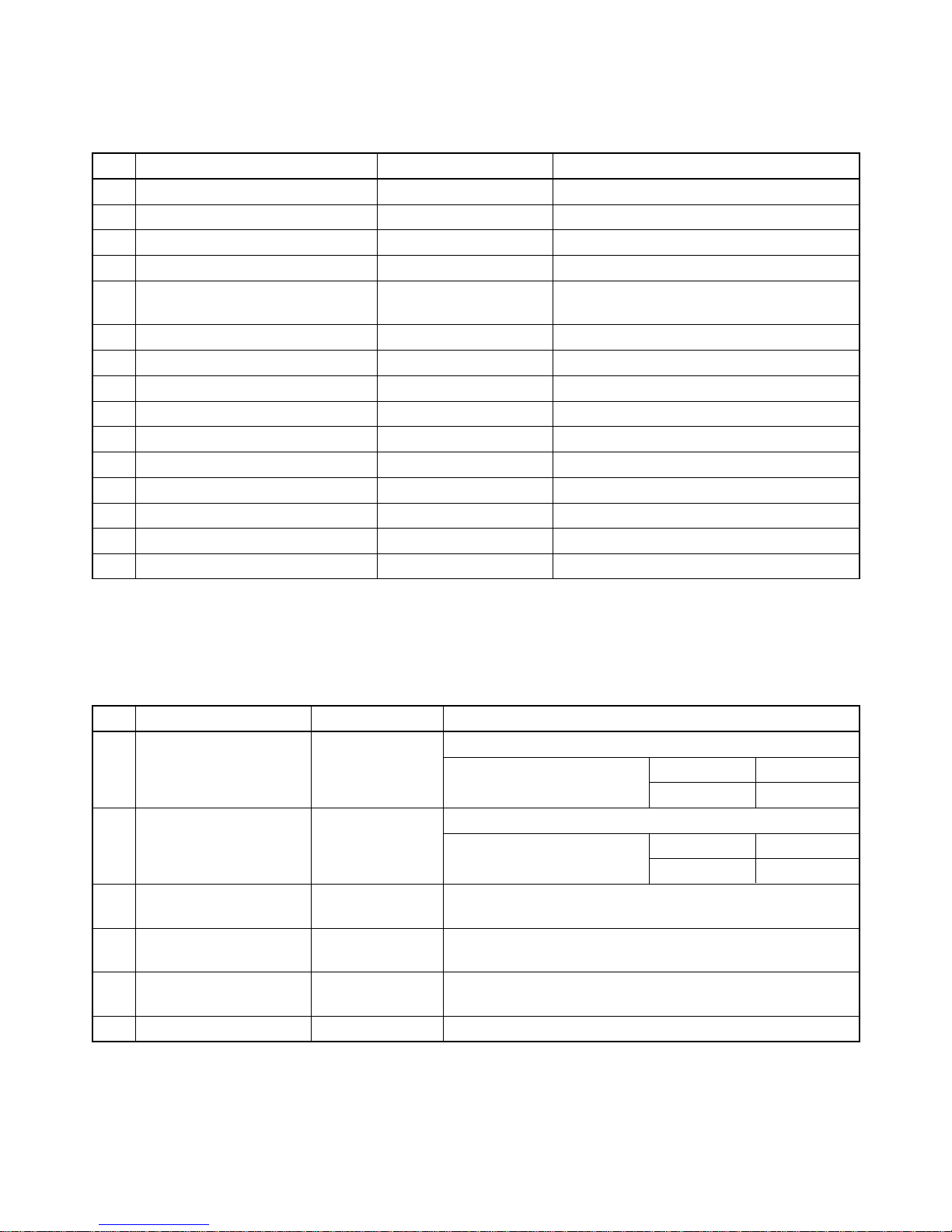
No. Parts name Type Specifications
1 Fan motor (for indoor) MMF-240-20-4A-1 AC Motor with 135°C thermo fuse
2 Thermo sensor (TA-sensor) ——— 10kΩ at 25°C
3 Switching transformer (T01) SWT-47
4 Microcontroller unit (IC30) TMP87CM40AN
5 Heat exchanger sensor
——— 10kΩ at 25°C
(TC-sensor)
6 Line filter (L01) LC*SS11V-06270 27mH, 600mA
7 Bridge rectifier (DB01) D3SBA60 4A, 60 V
8 Capacitor (C02) KMH400VSSN47M22S 47µF, 400 V
9 Fuse (F01) TSCR6.3A T6.3A, 250VAC
10 Varistor (R21, R22) 15G561K 560 V
11 Resistor (R01) RF-2TK5R6 5.6Ω, 2 W
12 Louver motor MP24GA 12VDC
13 Relay (Comp., RY01) DI12D1 Rating 20A/AC250 V, 12VDC
14 Relay (Fan, RY03) G5N-1A Rating 3A/AC250 V, 12VDC
15 Relay (Solenoide, RY04) G5N-1A Rating 3A/AC250 V, 12VDC
4-2.Outdoor Unit (RAS-13UAH-E2)
No. Parts name Type Specifications
Output (Rated) 1100 W, 2 poles, 1 phase, 220 – 240 V, 50Hz
1 Compressor PH170T2-4L2 Winding resistance (Ω) C-R C-S
(at 20°C) 2.22 3.04
Output (Rated) 42 W, 6 poles, 1 phase, 220 – 240 V, 50Hz
2 Fan motor (for outdoor) HF-240-42A Winding resistance (Ω) Red-Black White-Black
(at 20°C) 176.2 290.5
3
Running capacitor
DS45115CBPQC AC 450 V, 1.5µF
(for fan motor)
4
Running capacitor
DS371356CPN AC 370 V, 35µF
(for compressor)
5
Solenoid coil
VHV-01AJ503C1 AC 220 – 240 V, 50Hz
(for 4-way valve)
6 Overload relay JMRA99257-9200 U/T : 8.0A (80°C), OPEN : 145±5°C, CLOSE : 75±11°C

– 13 –
FILE NO. SVM-03004(1)
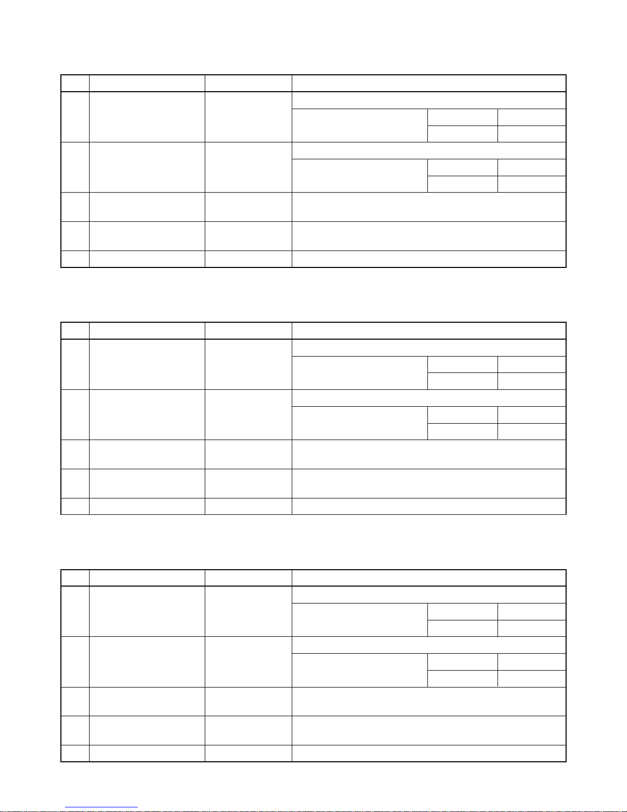
4-3.Outdoor Unit (RAS-10UAH-E2)
No. Parts name Type Specifications
Output (Rated) 750 W, 2 poles, 1 phase, 220 – 240 V, 50Hz
1 Compressor PH120T1-4C Winding resistance (Ω) C-R C-S
(at 20°C) 4.53 8.73
Output (Rated) 30 W, 6 poles, 1 phase, 220 – 240 V, 50Hz
2 Fan motor (for outdoor) HF-240-20B Winding resistance (Ω) Red-Black White-Black
(at 20°C) 387.3 466.2
3
Running capacitor
DS451155BPQC AC 450 V, 1.5µF
(for fan motor)
4
Running capacitor
DS371256CPNB AC 370 V, 25µF
(for compressor)
5
Solenoid coil
SQ-373 AC 220 – 240 V
(for 4-way valve)
6 Overload relay JMRA99269-9200 U/T : 6.8A (90°C), OPEN : 135±5°C, CLOSE : 69±11°C
4-4.Indoor Unit (RAS-13UKP-E2, RAS-10UKP-E2, RAS-13UKPX2, RAS-10UKPX2)
No. Parts name Type Specifications
1 Fan motor (for indoor) MMF-240-20-4A-1 AC Motor with 135°C thermo fuse
2 Thermo sensor (TA-sensor) ——— 10kΩ at 25°C
3 Switching transformer (T01) SWT-47
4 Microcontroller unit (IC30) TMP87CM40AN-2C67
5 Heat exchanger sensor
——— 10kΩ at 25°C
(TC-sensor)
6 Line filter (L01) LC*SS11V-06270 27mH, 600mA
7 Bridge rectifier (DB01) D3SBA60 4A, 600 V
8 Capacitor (C02) KMH400VSSN47M22S 47µF, 400 V
9 Fuse (F01) TSCR6.3A T6.3A, 250VAC
10 Varistor (R21, R22) 15G561K 560 V
11 Resistor (R01) RF-2TK5R6 5.6Ω, 2 W
12 Louver motor MP24GA 12VDC
13 Relay (Comp., RY01) DI12D1 Rating 20A/AC250 V, 12VDC
– 14 –
FILE NO. SVM-03004(1)
4-7.Outdoor Unit (RAS-10UA-E2)
No. Parts name Type Specifications
Output (Rated) 750 W, 2 poles, 1 phase, 220 – 240 V, 50Hz
1 Compressor 2PSI46D5AB02 Winding resistance (Ω) C-R C-S
(at 20°C) 3.60 4.87
Output (Rated) 20 W, 6 poles, 1 phase, 220 – 240 V, 50Hz
2 Fan motor (for outdoor) HF-240-20B Winding resistance (Ω) Red-Black White-Black
(at 20°C) 387.3 466.2
3
Running capacitor
DS451155BPQC AC 450 V, 1.5µF
(for fan motor)
4
Running capacitor
DS371256CPNB AC 370 V, 25µF
(for compressor)
5 Overload relay LPAP960B U/T : 6.1A (80°C), OPEN : 135±5°C, CLOSE : 78±11°C
4-5.Outdoor Unit (RAS-13UA-E2)
No. Parts name Type Specifications
Output (Rated) 1100 W, 2 poles, 1 phase, 220 – 240 V, 50Hz
1 Compressor PH160T2-4L2 Winding resistance (Ω) C-R C-S
(at 20°C) 2.43 3.78
Output (Rated) 42 W, 6 poles, 1 phase, 220 – 240 V, 50Hz
2 Fan motor (for outdoor) HF-240-20B Winding resistance (Ω) Red-Black White-Black
(at 20°C) 387.3 466.2
3
Running capacitor
DS45115CBPQC AC 450 V, 1.5µF
(for fan motor)
4
Running capacitor
DS371356CPN AC 370 V, 35µF
(for compressor)
5 Overload relay LAAO00A U/T : 9.0A (80°C), OPEN : 135±5°C, CLOSE : 75±11°C
4-6.Outdoor Unit (RAS-13UAX2)
No. Parts name Type Specifications
Output (Rated) 1100 W, 2 poles, 1 phase, 220 – 240 V, 50Hz
1 Compressor PH160T2-4LH2 Winding resistance (Ω) C-R C-S
(at 20°C) 2.43 3.78
Output (Rated) 30 W, 6 poles, 1 phase, 220 – 240 V, 50Hz
2 Fan motor (for outdoor) HF-240-30B Winding resistance (Ω) Red-Black White-Black
(at 20°C) 245 388
3
Running capacitor
DS451155BPQC AC 450 V, 1.5µF
(for fan motor)
4
Running capacitor
DS371356CPNB AC 370 V, 35µF
(for compressor)
5 Overload relay LAAO00A U/T : 9.0A (80°C), OPEN : 135±5°C, CLOSE : 75±11°C
– 15 –
FILE NO. SVM-03004(1)
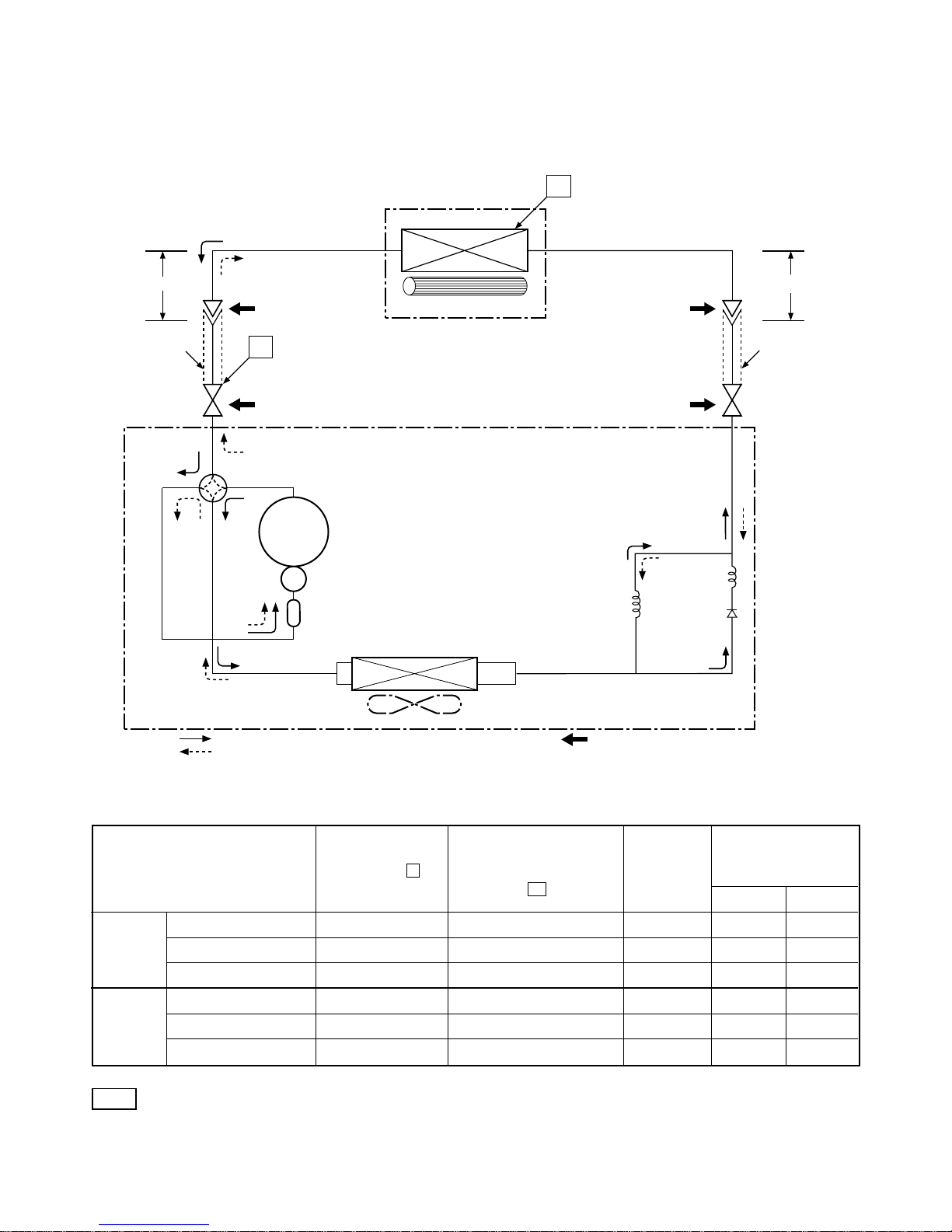
5. REFRIGERATION CYCLE DIAGRAM
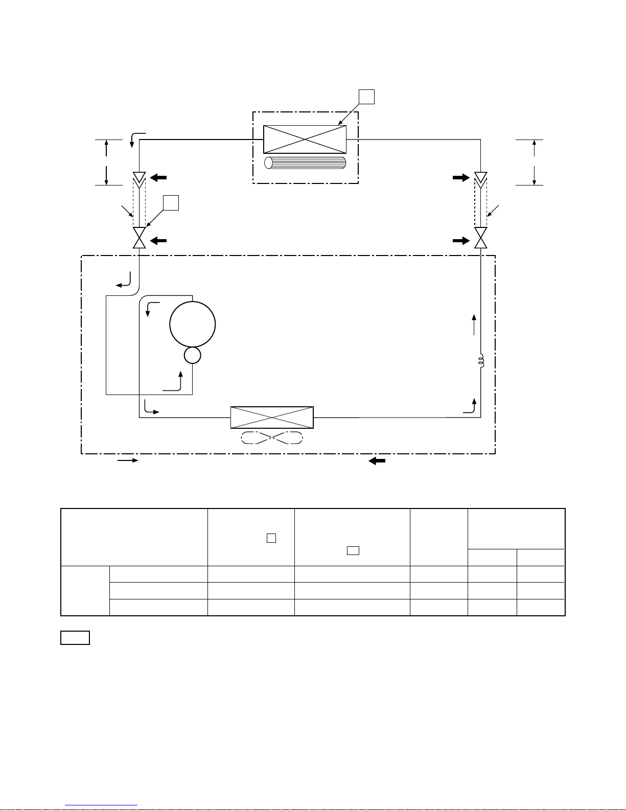
5-1.RAS-13UKHP-E2 / RAS-13UAH-E2
Evaporator
Indoor unit
Cross flow fan
Cooling
Heating
4-way valve
Heating
Cooling
Compressor
Accumulator
Condenser
Propeller fan
Outdoor unit
Capillary tube
∅1.0 x 900s
Capillary tube
∅1.5 x 700s
PH170T2-4L2
Cooling
Heating
Mark ( ) means check points of Gas Leak.
O.D.:12.7 mm O.D.:6.35 mm
Cooling
Heating
Packed valve
(∅12.7)
Packed valve
(∅6.35)
0.39 m
(Connecting pipe)
0.49 m
(Connecting pipe)
T1
P
Refrigerant
R22 : 1.00 kg.
∅12.7
∅6.35
Ambient temp.
conditions DB/WB
(°C)
Indoor Outdoor
Standard 1.84 46.0 High 20/15 7/6
Heating Overload*1 2.00 ~ 2.42 52.0 ~ 59.0 Low 27/– 24/18
Low temperature 1.50 38.0 High 20/––10/–10
Standard 0.49 10.0 High 27/19 35/24
Cooling Overload 0.60 15.0 High 32/23 43/26
Low temperature 0.45 2.0 Low 21/15 21/15
Standard
pressure
P
(MPaG)
Surface temp. of heat
exchanger interchanging
pipe
T1
(°C)
Fan speed
(indoor)
50Hz
Note
• Measure the heat exchanger temperature at the center of U-bend. (By means of TC sensor)
*1 • During heating overload operation, a value for the high temperature limit control operation is included.
– 16 –
FILE NO. SVM-03004(1)
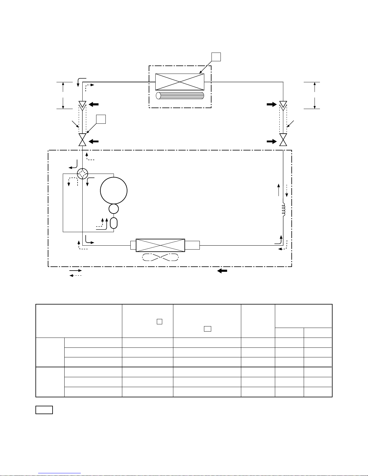
5-2.RAS-10UKHP-E2 / RAS-10UAH-E2
Indoor unit
Cross flow fan
Cooling
Heating
4-way valve
Heating
Cooling
Compressor
Condenser
Propeller fan
Outdoor unit
PH120T1-4C
Cooling
Heating
Mark ( ) means check points of Gas Leak.
O.D.:9.52 mm O.D.:6.35 mm
Cooling
Heating
Packed valve
(∅9.52)
Packed valve
(∅6.35)
0.39 m
(Connecting pipe)
∅9.52
0.49 m
(Connecting pipe)
∅6.35
T1
P
Refrigerant
R22 : 0.76 kg.
Capillary tube
∅1.5 x 900s
Accumulator
Evaporator
Ambient temp.
conditions DB/WB
(°C)
Indoor Outdoor
Standard 1.65 40.0 High 20/15 7/6
Heating Overload*1 2.00 ~ 2.40 52.0 ~ 59.0 Low 27/– 24/18
Low temperature 1.40 35.0 High 20/––10/–10
Standard 0.48 12.0 High 27/19 35/24
Cooling Overload 0.58 15.0 High 32/23 43/26
Low temperature 0.45 5.0 Low 21/15 21/15
Standard
pressure
P
(MPaG)
Surface temp. of heat
exchanger interchanging
pipe
T1
(°C)
Fan speed
(indoor)
50Hz
Note
• Measure the heat exchanger temperature at the center of U-bend. (By means of TC sensor)
*1 • During heating overload operation, a value for the high temperature limit control operation is included.

– 17 –
FILE NO. SVM-03004(1)
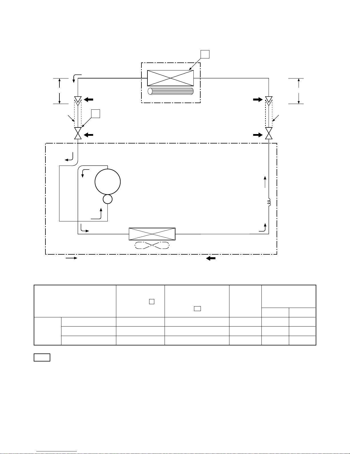
5-3.RAS-13UKP-E2 / RAS-13UA-E2
Note
• Measure the heat exchanger temperature at the center of U-bend. (By means of TC sensor)
Ambient temp.
conditions DB/WB
(°C)
Indoor Outdoor
Standard 0.48 9.0 High 27/19 35/24
Cooling Overload 0.59 15.0 High 32/23 43/26
Low temperature 0.45 2.0 Low 21/15 21/15
Standard
pressure
P
(MPaG)
Surface temp. of heat
exchanger interchanging
pipe
T1
(°C)
Fan speed
(indoor)
50Hz
Heat exchanger
Indoor unit
Cross flow fan
Cooling
Cooling
Compressor
Condenser
Propeller fan
Outdoor unit
Capillary tube
∅1.7 x 1000s
PH160T2-4LH2
Cooling
Mark ( ) means check points of Gas Leak.
O.D.:12.7 mm O.D.:6.35 mm
Cooling
Packed valve
(∅12.7)
Packed valve
(∅6.35)
0.39 m
(Connecting pipe)
∅12.7
0.49 m
(Connecting pipe)
∅6.35
T1
P
Refrigerant
R22 : 0.80 kg.
– 18 –
FILE NO. SVM-03004(1)
5-4.RAS-10UKP-E2 / RAS-10UA-E2
Indoor unit
Cross flow fan
Cooling
Cooling
Compressor
Condenser
Propeller fan
Outdoor unit
2PS146D5AB02
Cooling
Mark ( ) means check points of Gas Leak.
O.D.:9.52 mm O.D.:6.35 mm
Cooling
Packed valve
(∅9.52)
Packed valve
(∅6.35)
0.39 m
(Connecting pipe)
∅9.52
0.49 m
(Connecting pipe)
∅6.35
T1
P
Refrigerant
R22 : 0.68 kg.
Evaporator
Capillary tube
∅1.5 x 1000s
Ambient temp.
conditions DB/WB
(°C)
Indoor Outdoor
Standard 0.53 11.0 High 27/19 35/24
Cooling Overload 0.62 16.0 High 32/23 43/26
Low temperature 0.48 5.0 Low 21/15 21/15
Standard
pressure
P
(MPaG)
Surface temp. of heat
exchanger interchanging
pipe
T1
(°C)
Fan speed
(indoor)
50Hz
Note
• Measure the heat exchanger temperature at the center of U-bend. (By means of TC sensor)

– 19 –
FILE NO. SVM-03004(1)
5-5.RAS-13UKPX2 / RAS-13UAX2
Note
• Measure the heat exchanger temperature at the center of U-bend. (By means of TC sensor)
Ambient temp.
conditions DB/WB
(°C)
Indoor Outdoor
Standard 0.48 9.0 High 27/19 35/24
Cooling Overload 0.59 15.0 High 32/23 43/26
Low temperature 0.45 2.0 Low 21/15 21/15
Standard
pressure
P
(MPaG)
Surface temp. of heat
exchanger interchanging
pipe
T1
(°C)
Fan speed
(indoor)
50Hz
Heat exchanger
Indoor unit
Cross flow fan
Cooling
Cooling
Compressor
Condenser
Propeller fan
Outdoor unit
Capillary tube
∅1.7x1000s
PH160T2-4LH2
Cooling
Mark ( ) means check points of Gas Leak.
O.D.:12.7 mm O.D.:6.35 mm
Cooling
Packed valve
(∅12.7)
Packed valve
(∅6.35)
0.39 m
(Connecting pipe)
∅12.7
0.49 m
(Connecting pipe)
∅6.35
T1
P
Refrigerant
R22 : 0.80 kg.
– 20 –
FILE NO. SVM-03004(1)
5-6.RAS-10UKPX2 / RAS-10UAX2
Indoor unit
Cross flow fan
Cooling
Cooling
Compressor
Condenser
Propeller fan
Outdoor unit
PH102T1-4CH
Cooling
Mark ( ) means check points of Gas Leak.
O.D.:9.52 mm O.D.:6.35 mm
Cooling
Packed valve
(∅9.52)
Packed valve
(∅6.35)
0.39 m
(Connecting pipe)
∅9.52
0.49 m
(Connecting pipe)
∅6.35
T1
P
Refrigerant
R22 : 0.65 kg.
Evaporator
Capillary tube
∅1.5x1000s
Ambient temp.
conditions DB/WB
(°C)
Indoor Outdoor
Standard 0.53 11.0 High 27/19 35/24
Cooling Overload 0.62 16.0 High 32/23 43/26
Low temperature 0.48 5.0 Low 21/15 21/15
Standard
pressure
P
(MPaG)
Surface temp. of heat
exchanger interchanging
pipe
T1
(°C)
Fan speed
(indoor)
50Hz
Note
• Measure the heat exchanger temperature at the center of U-bend. (By means of TC sensor)
– 21 –
FILE NO. SVM-03004(1)
6. CONTROL BLOCK DIAGRAM
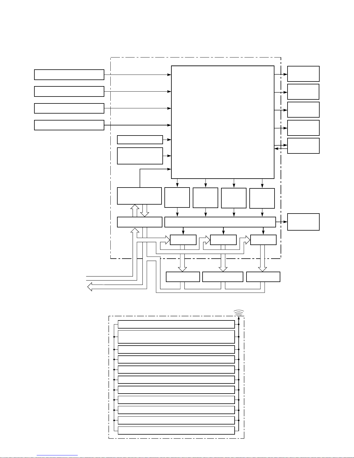
6-1.RAS-13UKHP-E2 / RAS-13UAH-E2, RAS-10UKHP-E2 / RAS-10UAH-E2
Heat Exchange sensor
Main Unit Control Panel
M.C.U.
Functions
Operation
Display
Timer
Display
Filter Sign
Display
PRE DEF.
Sign Display
Indoor Fan
Motor
Louver
Motor
Louver
ON/OFF
Signal
Compressor
ON/OFF
Signal
Outdoor Fan
ON/OFF
Signal
4-Way Valve
ON/OFF
Signal
Power Supply
Circuit
Noise Filter Relay Driver, Louver Driver
Relay
RY01
Relay
RY03
Relay
RY04
220 − 240 V~, 50Hz
Compressor 4-Way Valve
Outdoor Fan Motor
• Louver Control
• 3-minutes Delay at Restart
for Compressor
• Processing
(Temperature Processing)
• Motor Revolution Control
• Timer
Initiallizing Circuit
Clock Frequency
Oscillator Circuit
Thermo. Sensor
Current Sensor
(Compressor Current)
Infrared Rays Signal Reciver
REMOTE CONTROL
Remote Control
Operation (START/STOP)
Operation Mode Selection
AUTO, COOL, DRY, HEAT, FAN ONLY
Temperature Setting
Fan Speed Selection
ON TIMER Setting
OFF TIMER Setting
Louver Auto Swing
Louver Direction Setting
ECO
Hi power
Filter Reset
Infrared Rays
– 22 –
FILE NO. SVM-03004(1)
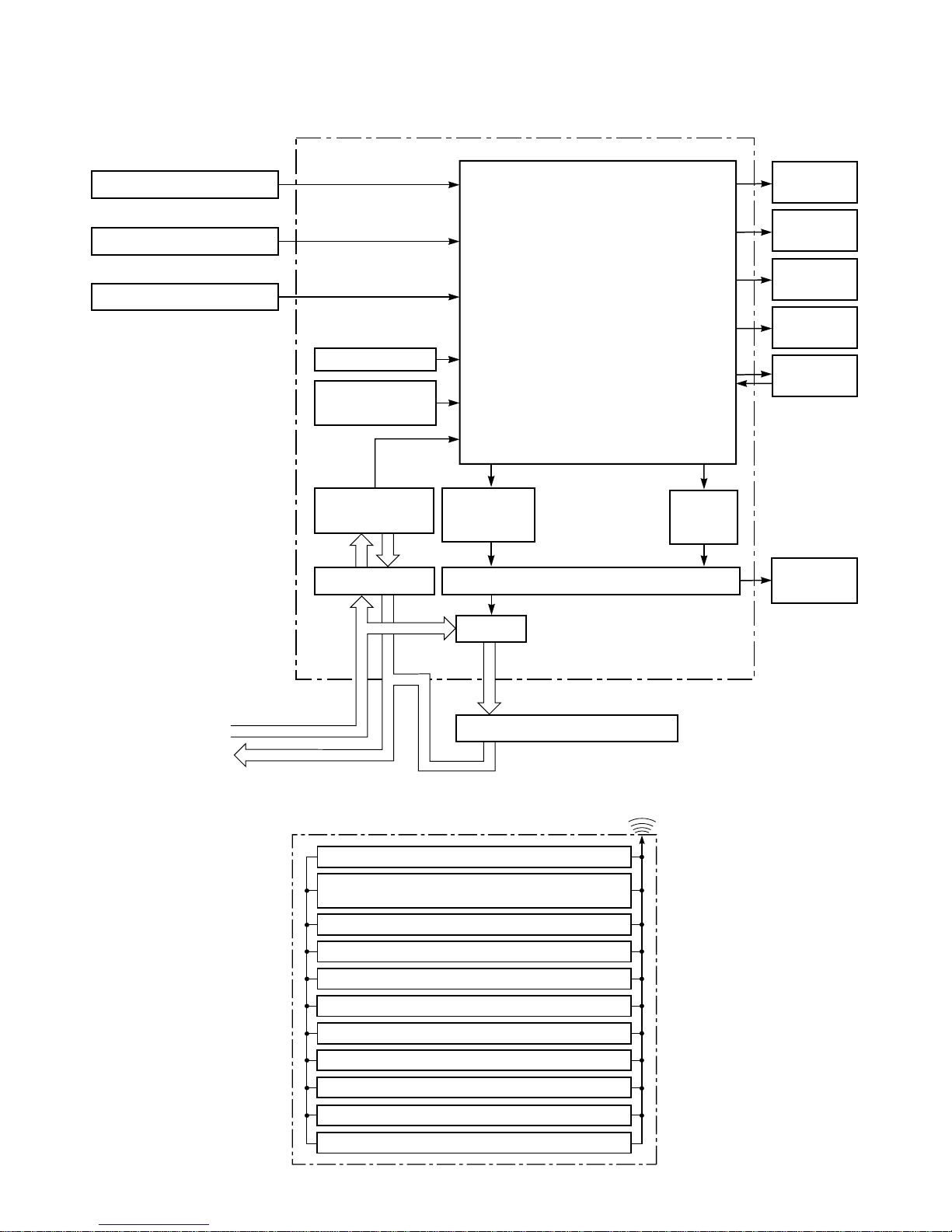
REMOTE CONTROL
Remote Control
Operation (START/STOP)
Operation Mode Selection
AUTO, COOL, DRY, FAN ONLY
Temperature Setting
Fan Speed Selection
ON TIMER Setting
OFF TIMER Setting
Louver Auto Swing
Louver Direction Setting
ECO
Hi power
Filter Reset
Infrared Rays
Heat Exchange sensor
Main Unit Control Panel M.C.U.
Functions
Operation
Display
Timer
Display
Filter Sign
Display
Fan Only
Sign Display
Indoor Fan
Motor
Louver
Motor
Louver
ON/OFF
Signal
Compressor
ON/OFF
Signal
Power Supply
Circuit
Noise Filter Relay Driver, Louver Driver
Relay
RY01
220 − 240 V~, 50Hz
Compressor, Outdoor Fan Motor
Initiallizing Circuit
Clock Frequency
Oscillator Circuit
• Louver Control
• 3-minutes Delay at Restart
for Compressor
• Processing
(Temperature Processing)
• Motor Revolution Control
• Timer
Thermo. Sensor
Infrared Rays Signal Reciver
6-2.RAS-13UKP-E2 / RAS-13UA-E2, RAS-10UKP-E2 / RAS-10UA-E2
RAS-13UKPX2 / RAS-13UAX2 , RAS-10UKPX2 / RAS-10UAX2
 Loading...