

Toshiba RAS-13UAH-E, RAS-13UAX, RAS-13UKP-E, RAS-13UKPX, RAS-10UKHP-E Service Manual
...
SERVICE MANUAL
AIR-CONDITIONER
SPLIT WALL TYPE
FILE NO. SVM-02001
RAS-13UKHP-E / RAS-13UAH-E
RAS-13UKP-E / RAS-13UA-E
RAS-13UKPX / RAS-13UAX
RAS-10UKHP-E / RAS-10UAH-E
RAS-10UKP-E / RAS-10UA-E
RAS-10UKPX / RAS-10UAX-1
10/13 Class
Apr., 2002

– 1 –
FILE NO. SVM-02001
CONTENTS
1. SPECIFICATIONS
2. CONSTRUCTION VIEWS
2-1 Indoor Unit
2-2 Outdoor Unit (RAS-13UAH-E, RAS-13UA-E)
2-3 Outdoor Unit (RAS-10UAH-E, RAS-10UA-E, RAS-10UAX-1)
3. WIRING DIAGRAM
3-1 RAS-13UKHP-E / RAS-13UAH-E
3-2 RAS-10UKHP-E / RAS-10UAH-E
3-3 RAS-13UKP-E / RAS-13UA-E, RAS-13UKPX / RAS-13UAX
RAS-10UKP-E / RAS-10UA-E, RAS-10UKPX / RAS-10UAX-1
4. SPECIFICATION OF ELECTRICAL PARTS
4-1 Indoor Unit (RAS-13UKHP-E, RAS-10UKHP-E, RAS-07UKHP-E)
4-2 Outdoor Unit (RAS-13UAH-E)
4-3 Outdoor Unit (RAS-10UAH-E)
4-4 Indoor Unit (RAS-13UKP-E, RAS-10UKP-E, RAS-07UKP-E, RAS-13UKPX, RAS-10UKPX,
RAS-07UKPX)
4-5 Outdoor Unit (RAS-13UA-E, RAS-13UAX)
4-6 Outdoor Unit (RAS-10UA-E, RAS-10UAX-1)
5. REFRIGERATION CYCLE DIAGRAM
5-1 RAS-13UKHP-E / RAS-13UAH-E
5-2 RAS-13UKP-E / RAS-13UA-E, RAS-13UKPX / RAS-13UAX
5-3 RAS-10UKHP-E / RAS-10UAH-E
5-4 RAS-10UKP-E / RAS-10UA-E
5-5 RAS-10UKPX / RAS-10UAX-1
6. CONTROL BLOCK DIAGRAM
6-1 RAS-13UKHP-E / RAS-13UAH-E
RAS-10UKHP-E / RAS-10UAH-E
RAS-07UKHP-E / RAS-07UAH-E
6-2 RAS-13UKP-E / RAS-13UA-E, RAS-13UKPX / RAS-13UAX
RAS-10UKP-E / RAS-10UA-E, RAS-10UKPX / RAS-10UAX-1
RAS-07UKP-E / RAS-07UA-E, RAS-07UKPX / RAS-07UAX-1
7. OPERATION DESCRIPTION
7-1 Outline of Air Conditioner Control
7-2 Description of Operation Circuit
7-3 Hi POWER Mode
7-4 High-Temperature Limit Control
7-5 Low-Temperature Limit Control
7-6 Defrost Operation
7-7 Current Limit Control
7-8 Auto Restart Function
7-9 Filter Check Lamp

– 2 –
FILE NO. SVM-02001
8. INSTALLATION PROCEDURE
8-1 Safety Cautions
8-2 Installation Diagram of Indoor and Outdoor Units
8-3 Installation
8-4 Indoor Unit
8-5 Outdoor Unit
8-6 How to Set Remote Control Selector Switch
8-7 Others
9. TROUBLESHOOTING CHART
9-1 Troubleshooting Procedure
9-2 Basic Check Items
9-3 Primary Judgement
9-4 Self-Diagnosis by Remote Control (Check Code)
9-5 Troubleshooting Flowcharts
9-6 Troubleshooting for Remote Control (Including The Indoor P.C. Board)
10. PARTS REPLACEMENT
10-1 Indoor Unit
10-2 Outdoor Unit (RAS-13UAH-E)
10-3 Outdoor Unit (RAS-13UA-E, RAS-13UAX)
10-4 Outdoor Unit (RAS-10UAH-E)
10-5 Outdoor Unit (RAS-10UA-E, RAS-10UAX-1)
11. EXPLODED VIEWS AND PARTS LIST
11-1 Indoor Unit (1)
11-2 Indoor Unit (2)
11-3 Outdoor Unit (RAS-13UAH-E)
11-4 Outdoor Unit (RAS-13UA-E)
11-5 Outdoor Unit (RAS-13UAX)
11-6 Outdoor Unit (RAS-10UAH-E)
11-7 Outdoor Unit (RAS-10UA-E)
11-8 Outdoor Unit (RAS-10UAX-1)
– 3 –
FILE NO. SVM-02001
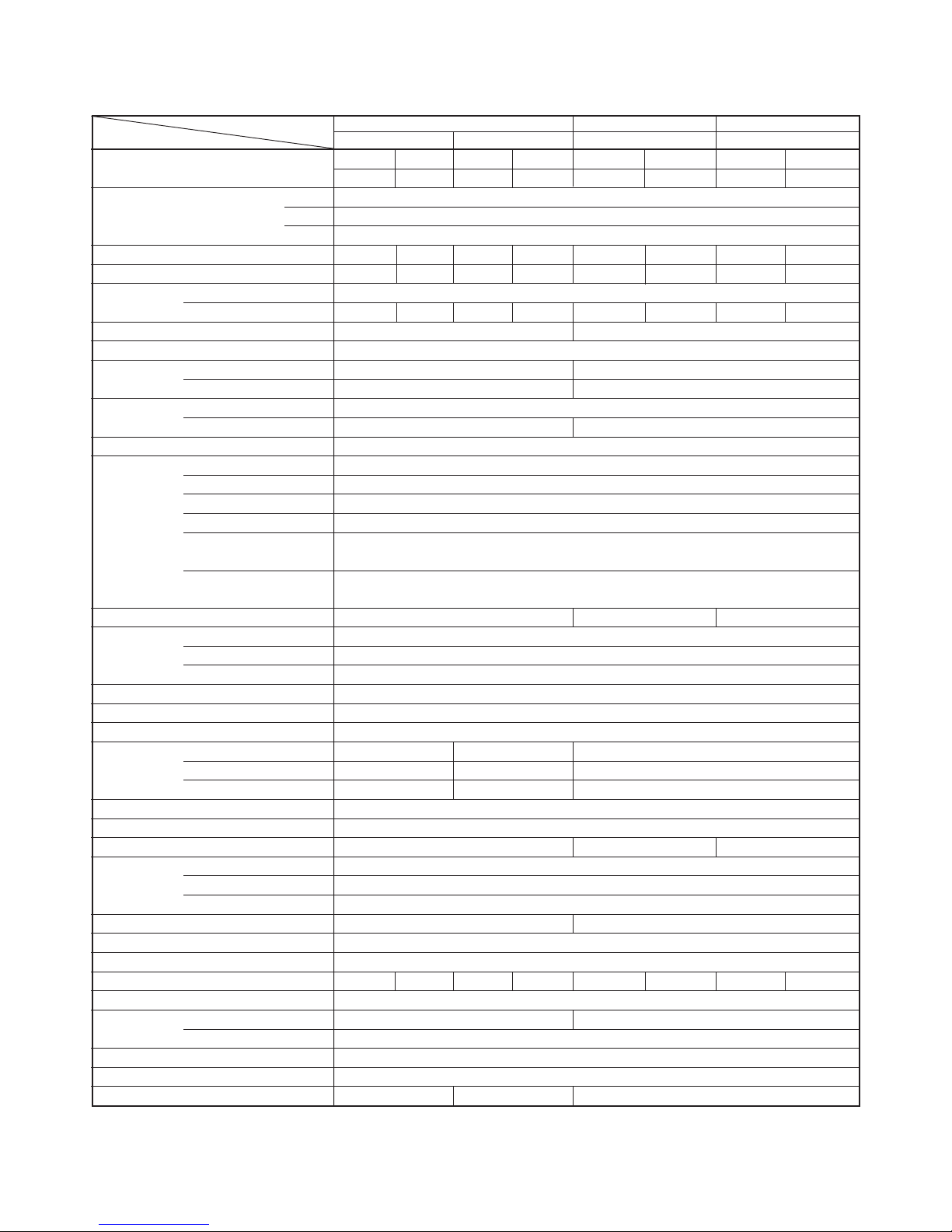
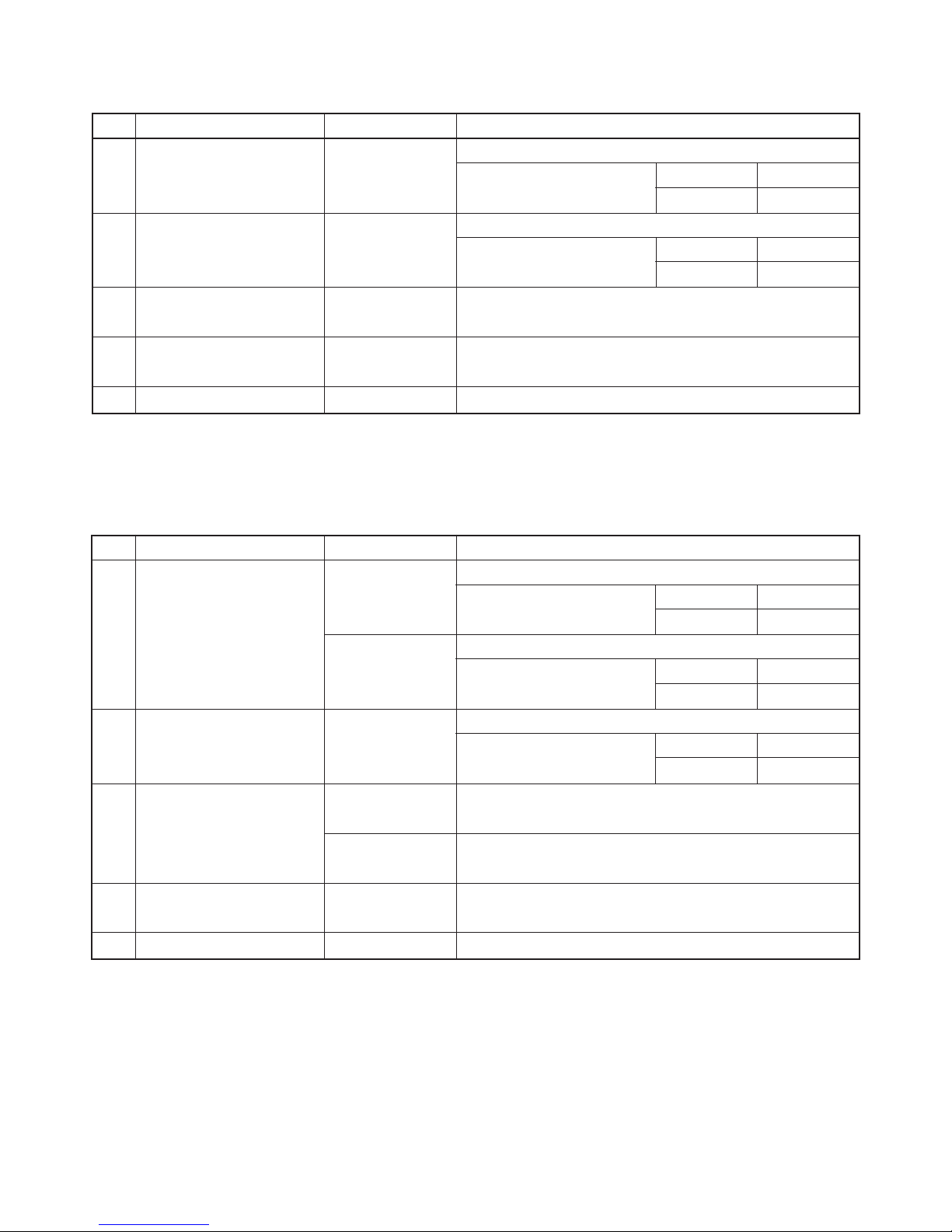
ITEM
MODEL
RAS-13UKHP-E / RAS-13UAH-E RAS-13UKP-E / RAS-13UA-E RAS-13UKPX / RAS-13UAX
Cooling Heating Cooling Cooling
Capacity kW
220V 240V 220V 240V 220V 240V 220V 240V
3.55 3.60 4.25 4.30 3.70 3.75 3.70 3.75
Phase
1∅
V
220 – 240
Hz 50
Power consumption kW 1.27 1.32 1.26 1.33 1.25 1.29 1.25 1.29
Power factor % 98 96 98 96 98 95 98 95
Running Indoor A 0.15
current Outdoor A 5.75 5.60 5.70 5.65 5.66 5.53 5.66 5.53
Starting current A 25 24
Moisture removal lit/h 2.0
Noise
Indoor (H/M/L) dB 41/35/31 41/35/31
Outdoor (220-240V) dB 49-51 47-48
Refrigerant
Name of refrigerant R22
Rated amount kg 1.10 0.78
Refrigerant control Capillary tube
Gas side size mm Ø 12.7
Connection type Flare connection
Liquid side size mm Ø 6.35
Connection type Flare connection
Maximum length
m15*
1
(One way)
Maximum height
m6
difference
INDOOR UNIT RAS-13UKHP-E RAS-13UKP-E RAS-13UKPX
Height mm 275
Dimensions Width mm 790
Depth mm 208
Net weight kg 10
Evaporator type Finned tube
Indoor fan type Cross flow fan
High fan m3/h 630 650 630
Air volume Medium fan m3/h 520 550 550
Low fan m3/h 430 490 460
Fan motor output W 30
Air filter Honeycomb woven filter with PP frame
OUTDOOR UNIT RAS-13UAH-E RAS-13UA-E RAS-13UAX
Height mm 538
Dimensions Width mm 780
Depth mm 300
Net weight kg 42 37
Condenser type Finned tube
Outdoor fan type Propeller fan
Airflow volume m3/h 1690 1730 1690 1730 1700 1900 1700 1900
Fan motor output W 42 30
Compressor Model PH170T2-4L2 PH160T2-4L2
Output W 1100
Safety device Fuse, Overload relay
Louver type Automatic louver
Usable outdoor temperature range °C 21 ~ 43 –5 ~ 21 21 ~ 43
Interconnection
pipe
Power source
1. SPECIFICATIONS
– 4 –
FILE NO. SVM-02001
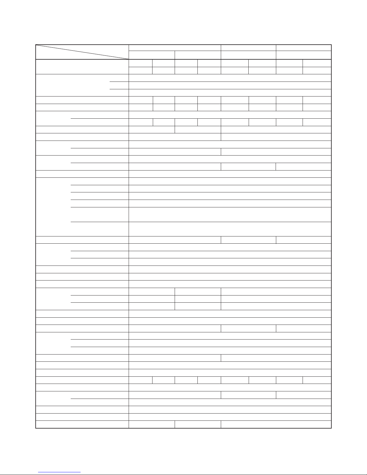
ITEM
MODEL
RAS-10UKHP-E / RAS-10UAH-E RAS-10UKP-E / RAS-10UA-E RAS-10UKPX / RAS-10UAX-1
Cooling Heating Cooling Cooling
Capacity kW
220V 240V 220V 240V 220V 240V 220V 240V
2.70 2.75 3.12 3.15 2.65 2.70 2.65 2.70
Phase
1Ø
V
220 – 240
Hz 50
Power consumption kW 1.00 1.05 0.89 0.91 0.80 0.85 0.80 0.85
Power factor % 97 91 94 87 96 94 96 94
Running Indoor A 0.15
current Outdoor A 4.55 4.60 4.15 4.20 3.65 3.60 3.65 3.60
Starting current A 19 14 16
Moisture removal lit/h 2.0 1.2
Noise
Indoor (H/M/L) dB 39/33/26
Outdoor (220-240V) dB 47-49 44-45
Refrigerant
Name of refrigerant R22
Rated amount kg 0.74 0.7 0.74
Refrigerant control Capillary tube
Gas side size mm Ø 9.52
Connection type Flare connection
Liquid side size mm Ø 6.35
Connection type Flare connection
Maximum length
m10*
1
(One way)
Maximum height
m5
difference
INDOOR UNIT RAS-10UKHP-E RAS-10UKP-E RAS-10UKPX
Height mm 275
Dimensions Width mm 790
Depth mm 208
Net weight kg 10
Evaporator type Finned tube
Indoor fan type Cross flow fan
High fan m3/h 570 610 630
Air volume Medium fan m3/h 460 520 490
Low fan m3/h 340 400 370
Fan motor output W 30
Air filter Honeycomb woven filter with PP frame
OUTDOOR UNIT RAS-10UAH-E RAS-10UA-E RAS-10UAX -1
Height mm 530
Dimensions Width mm 770
Depth mm 200
Net weight kg 31 29
Condenser type Finned tube
Outdoor fan type Propeller fan
Airflow volume m3/h 1500 1700 1500 1700 1500 1700 1500 1700
Fan motor output W 20
Compressor Model PH120T1-4C 2PS146D5AB02 PH102T1-4C
Output W 750
Safety device Fuse, Overload relay
Louver type Automatic louver
Usable outdoor temperature range °C 21 ~ 43 –5 ~ 21 21 ~ 43
Interconnection
pipe
Power source
– 5 –
FILE NO. SVM-02001
Note : 1
• Capacity is based on the following temperature conditions.
Note : 2
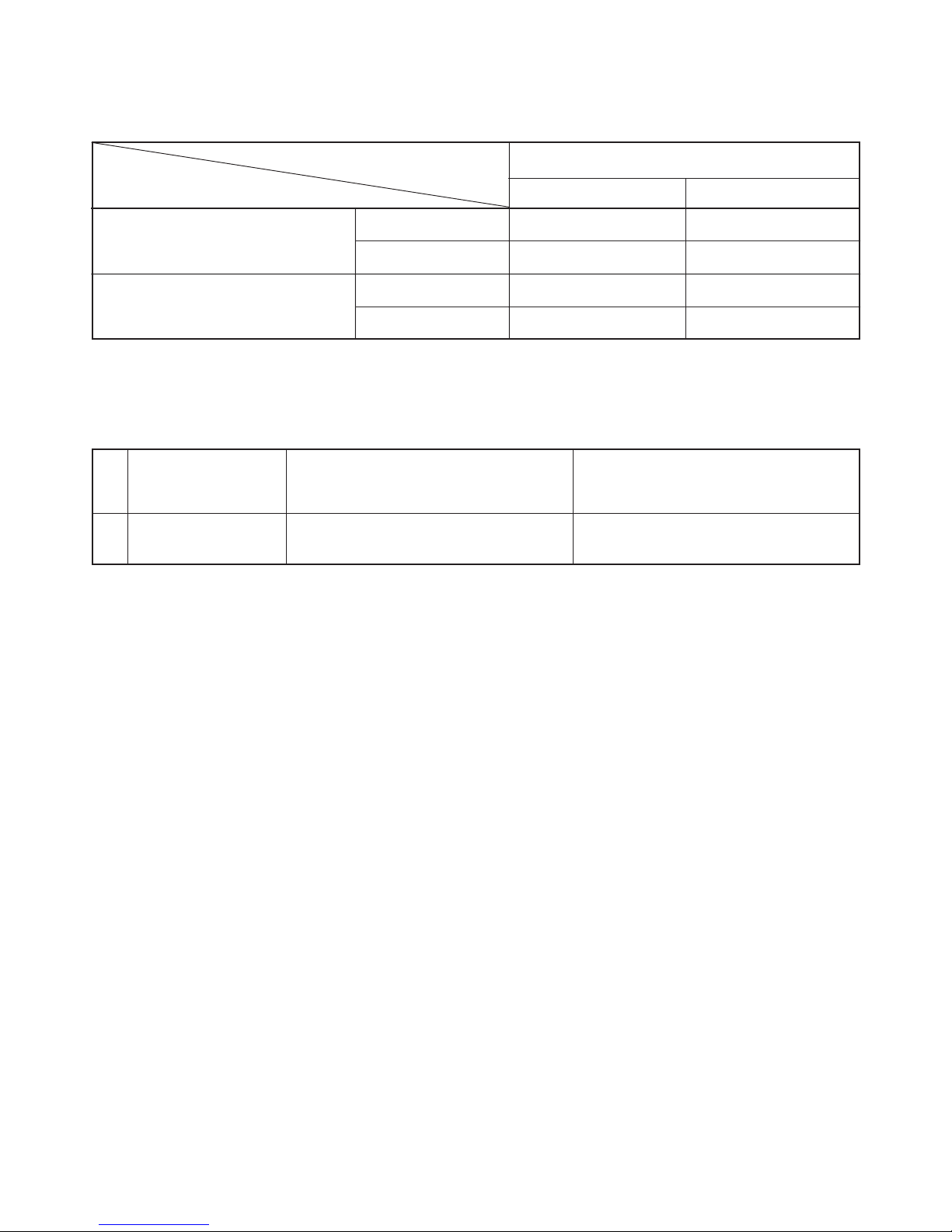
• Charge refrigerant according to the table below.
Refrigerant
*1 No need to charge
refrigerant
RAS-13UKHP-E / RAS-13UAH-E
RAS-13UKP-E / RAS-13UA-E
RAS-13UKPX / RAS-13UAX
15m or less
RAS-10UKHP-E / RAS-10UAH-E
RAS-10UKP-E / RAS-10UA-E
RAS-10UKPX / RAS-10UAX-1
10m or less
Temperature
Condition
JIS C9612-1994
Cooling Heating
(DB) 27 °C 20 °C
(WB) 19 °C 12 °C
(DB) 35 °C 7 °C
(WB) 24 °C 6 °C
Indoor unit inlet air temperature
Outdoor unit inlet air temperature
– 6 –
FILE NO. SVM-02001
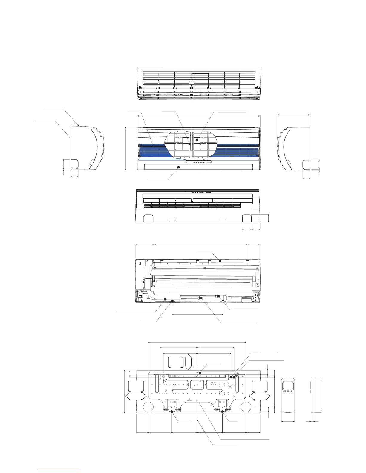
2. CONSTRUCTION VIEWS
2-1. Indoor Unit
Connecting pipe (0.33m)
(For 07,10 series ; Flare ∅9.52
For 13 series ; Flare ∅12.7)
Knock out system
Back body
Front panel
Air outlet
Air inlet
Air filter
Heat exchanger
Knock out system
660
275
790
208
48
48
26
4519040
32
64
590
320
620
235 235
215 215
9090
275
45
150150 160160
120 80
53
660
Hanger
Hanger
Hanger
Hanger
Hanger
Drain hose (0.54m)
Connecting pipe (0.43m)
(Flare ∅6.35)
For stud bolt
(∅8~∅10)
For stud bolt (∅6)
Installation plate outline
Center line
Minimum
distance
to ceiling
170 or more
Minimum
distance
to ceiling
170 or more
65 or more
Minimum
distance
to ceiling
Wireless remote control
57 18
160
– 7 –
FILE NO. SVM-02001
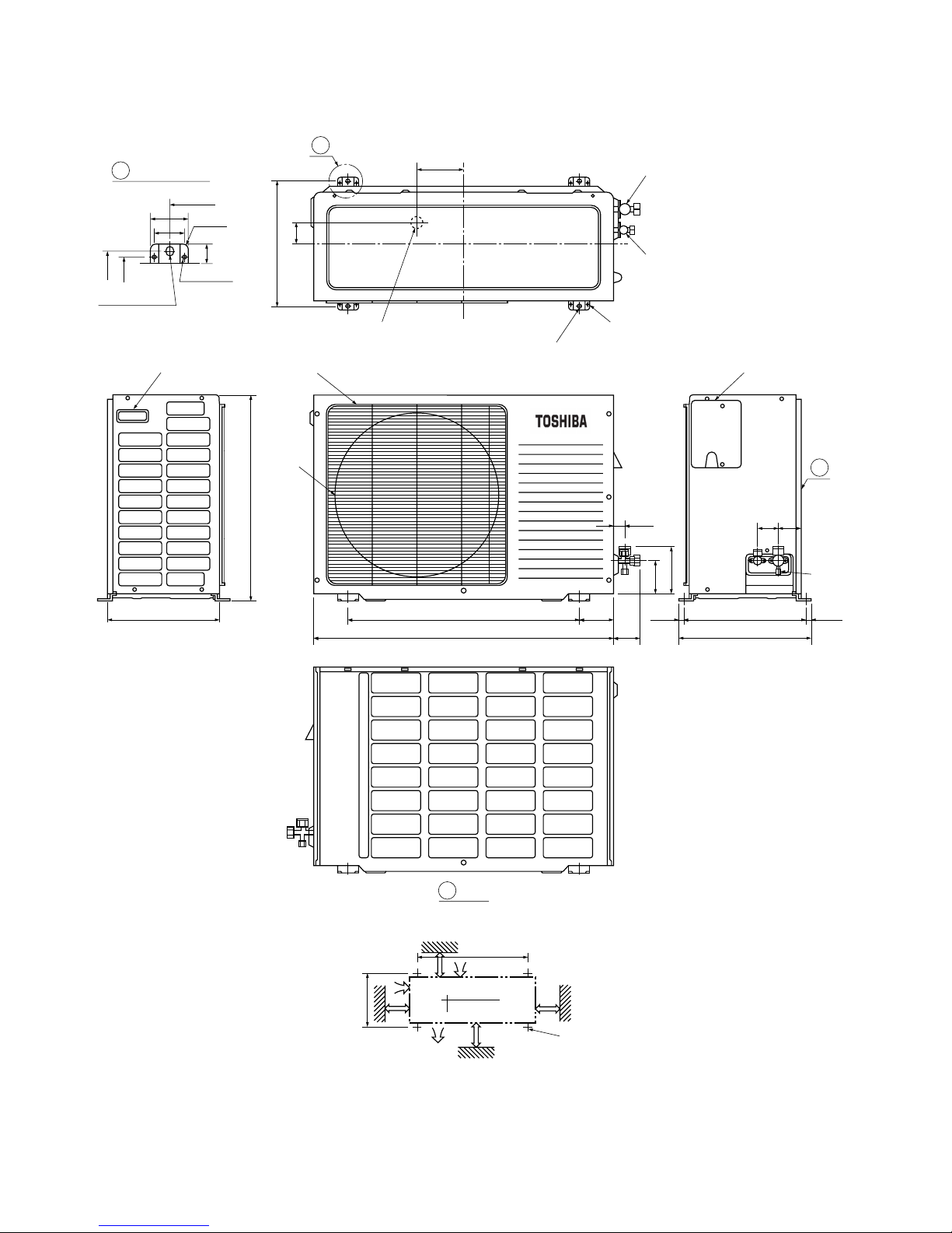
538
325
325
52.5
23
301
325
300
Handle
∅25Drain outlet
Electric parts cover
Service
port
61
54
325 (pitch)
(8.5)
(8.5)
342
100 or more
100 or more
600 or more
600 or more
Installation dimension
600
Air inlet
Air outlet
8-∅6 hole (for fixing outdoor unit)
Liquid side (Flare ∅6.35)
Gas side (Flare ∅12.7)
120
∅11x14 hole
∅6 hole
R10
600
Detail Drawing
50
36
A
A
4-∅11x14 hole (for ∅8-∅10 anchor bolt)
600
100
130
780
90
59
27
Fan guard
∅420
Z
View
Z
4x∅11x14 Long holes (for ∅8-∅10 anchor bolt)
2-2. Outdoor Unit (RAS-13UAH-E, RAS-13UA-E, RAS-13UAX)
– 8 –
FILE NO. SVM-02001
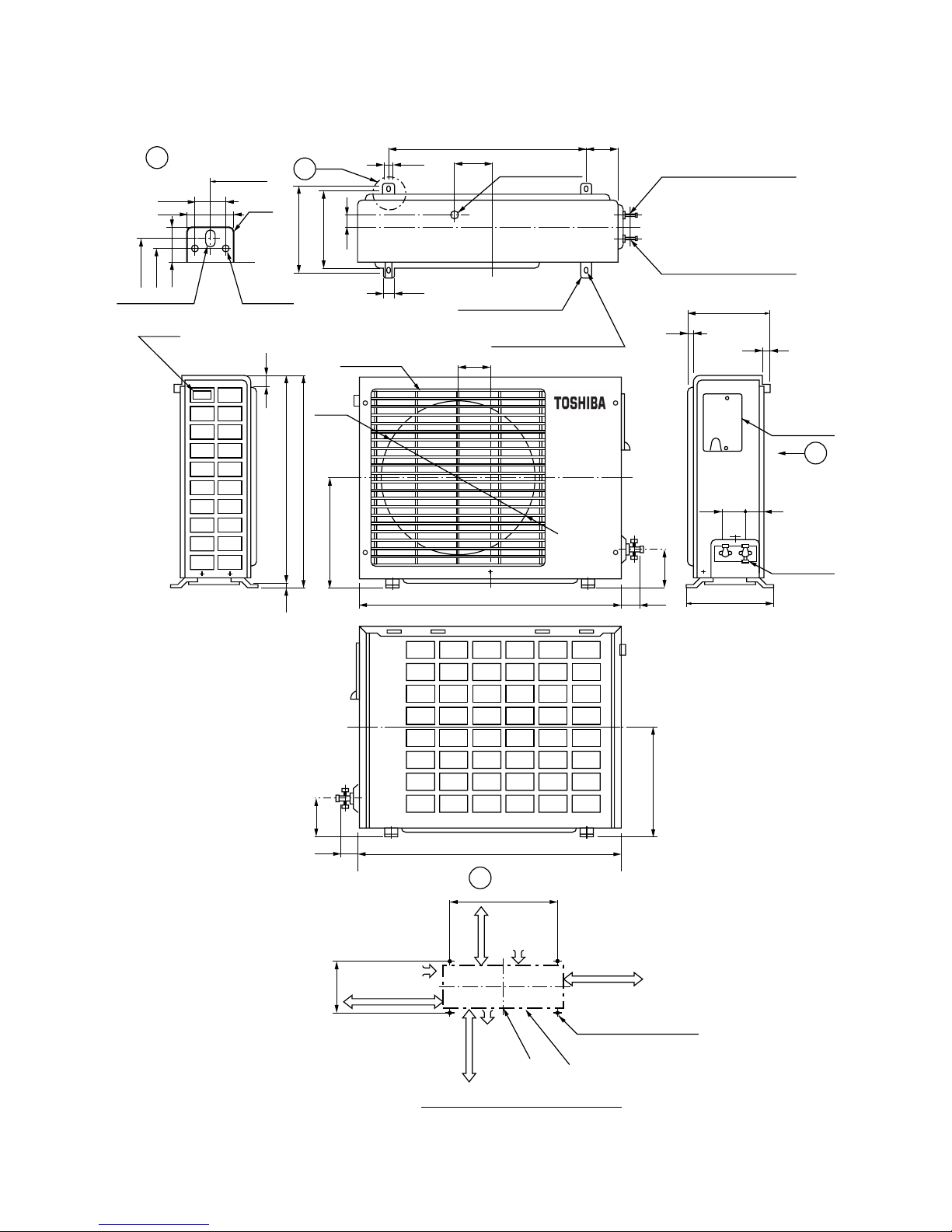
600 85
36
111
∅25 Drain hole
50
30
216
230
8-∅6 Holes
(For fixing the outdoor unit)
4-∅11x14 Long holes
(For anchor bolt ∅8-∅10)
Gas side (flare ∅9.52)
Liquid side (flare ∅6.35)
111
A
600
R10
50
36
25
216
230
∅11x14 Hole
∅6 Hole
Handle
11
525
530
5
268
Fan guard
∅420
770
59
89
200
11
12
Electric
parts cover
Z
54 62
Access for
charging
250
Z
View
600
45 or more
Air inlet
600 or more
(Minimum distance
of the wall)
4-∅11x14 Long holes
400 or more
Air
outlet
Center
port
230
100 or more
Air inlet
Visible outline of the product
A
Detail Drawing
Mounting dimension of anchor bolt
268
770
59
89
(For anchor bolt ∅8-∅10)
2-3. Outdoor Unit (RAS-10UAH-E, RAS-10UA-E, RAS-10UAX-1)
– 9 –
FILE NO. SVM-02001
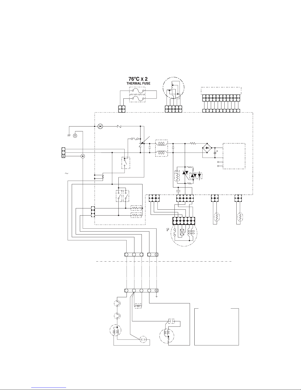
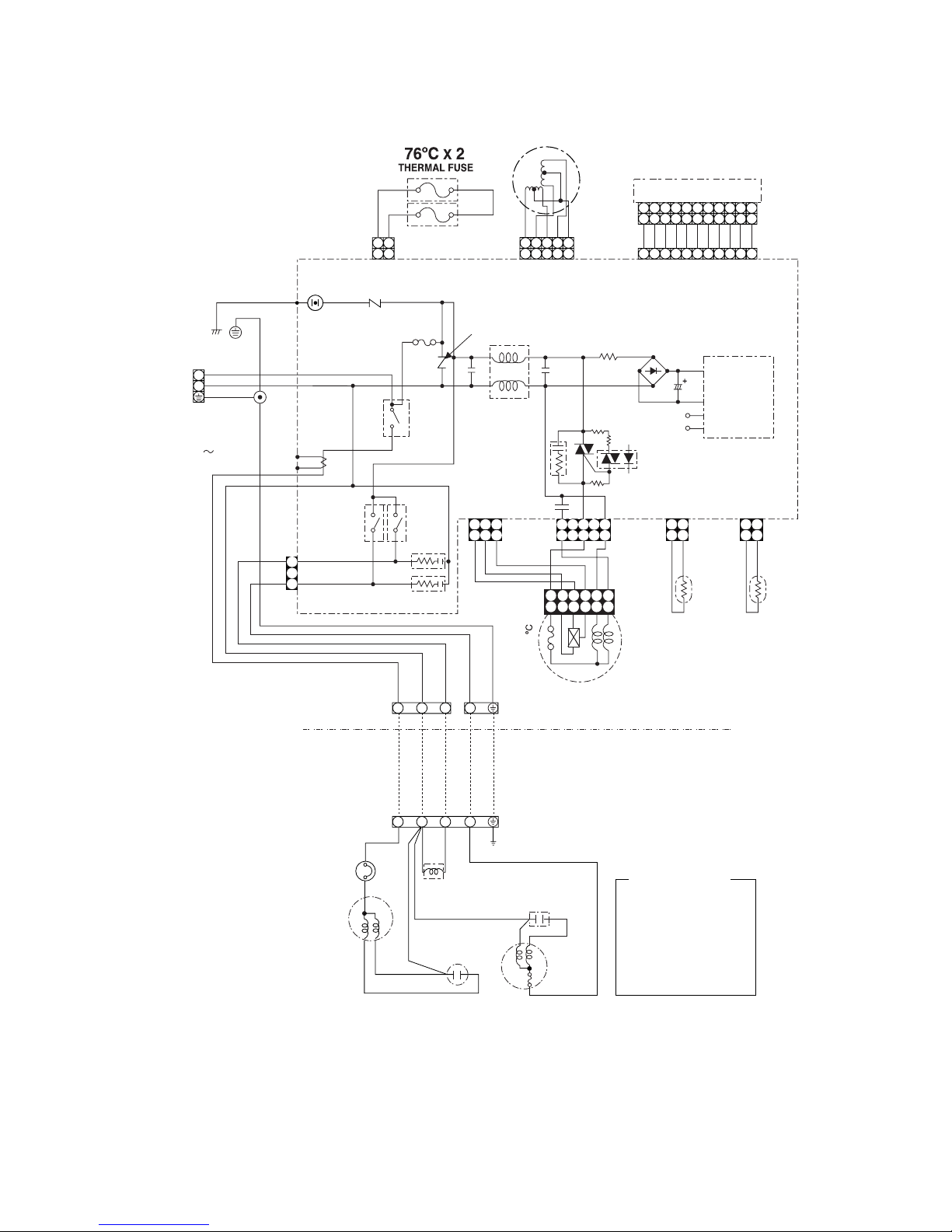
3. WIRING DIAGRAM
3-1. RAS-13UKHP-E / RAS-13UAH-E
BLU
BLU
BLU
BLU
BLU
BLU
BLU
BLU
BLU
BLU
WHI
YEL
CN25
CN13
CN07
BLK
GRN&YEL
POWER
TERMINAL
BLOCK
POWER SUPPLY
SINGLE PHASE
220-240V ,
50 Hz
BRW
BLU
GRN&YEL
BLK
RY03
RY04
YEL
BLK
WHI
RED
BLU
GRN&YEL
135
GRY
BRW
BLK
WHI
RED
CR01
CR02
CN27
INDOOR
TERMINAL
BLOCK
OUTDOOR
TERMINAL
BLOCK
OVER LOAD
RELAY
BLK
BLK
RED
RED
WHI
RED
PNK
CAPACITOR
SOLENOID
COIL
GRN & YEL
CHASSIS
CAPACITOR
FAN
MOTOR
BLK
BLK
BLK
WHI
BLK
THERMOSTAT
COMPRESSOR
WHI
T02
C.T
DSA
VARISTOR
RY01
4
3
F01
C15
L01
IC03
C58
R48
CN01CN03
THERMO
SENSOR
(TA)
HEAT
EXCHANGER
SENSOR
(TC)
CN10
R46
CR03
D38
C01 R01
DB01
POWER
SUPPLY
CIRCUIT
C02
DC 12V
DC 5V
R21
VARISTOR
MAIN P.C. BOARD
MCC-862
T6.3A
250V
P04
SG01
CN04
R22
PNK
PNK
YEL
YEL
YEL
WHI
INFRARED RAYS RECEIVE
AND INDICATION PARTS
CN11
AC FAN MOTOR
INDOOR
OUTDOOR
BLK
BLK
1
35
1
35
24
24
6
6
4 5 6 7 8 9
10 11
3
1
2
3
2
1 4
3
2
1 4
4 5 6 7 8 9
10 11
3
1
2
4 5 6 7 8 9
10 11
3
1
2
2 1
3
5
4
2 1
3
5
4
1
2
1
2
N
L
1
3
5
1
3
5
1
2
1
2
3
3
112
2
BLK
BLK
112
2
1
3
:
:
:
:
:
:
:
:
:
:
:
BROWN
RED
WHITE
YELLOW
BLUE
BLACK
GRAY
PINK
ORANGE
GREEN &
GREENGRN
YELLOW
BRW
RED
WHI
YEL
BLU
BLK
GRY
PNK
ORN
GRN&YEL
COLOR IDENTIFICATION
R47
Louver motor
– 10 –
FILE NO. SVM-02001
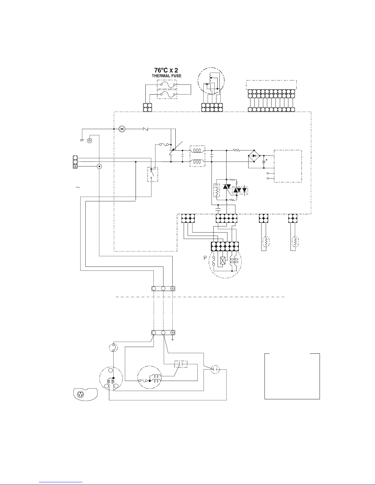
3-2. RAS-10UKHP-E / RAS-10UAH-E
OVER LOAD
RELAY
BLK
RED
RED
WHI
RED
PNK
CAPACITOR
SOLENOID
COIL
GRN & YEL
CHASSIS
CAPACITOR
FAN
MOTOR
BLK
BLK
BLK
WHI
COMPRESSOR
BLU
BLU
BLU
BLU
BLU
BLU
BLU
BLU
BLU
BLU
WHI
YEL
CN25
CN13
CN07
BLK
GRN&YEL
POWER
TERMINAL
BLOCK
POWER SUPPLY
SINGLE PHASE
220-240V ,
50 Hz
BRW
BLU
BLK
RY03
RY04
YEL
BLK
WHI
RED
BLU
GRN&YEL
135
GRY
BRW
BLK
WHI
RED
CR01
CR02
CN27
INDOOR
TERMINAL
BLOCK
OUTDOOR
TERMINAL
BLOCK
WHI
T02
C.T
DSA
VARISTOR
RY01
4
3
F01
C15
L01
IC03
C58
R48
CN01CN03
THERMO
SENSOR
(TA)
HEAT
EXCHANGER
SENSOR
(TC)
CN10
R46
CR03
D38
C01 R01
DB01
POWER
SUPPLY
CIRCUIT
C02
DC 12V
DC 5V
R21
VARISTOR
MAIN P.C. BOARD
MCC-862
T6.3A
250V
P04
SG01
CN04
R22
PNK
PNK
YEL
YEL
YEL
WHI
INFRARED RAYS RECEIVE
AND INDICATION PARTS
CN11
AC FAN MOTOR
INDOOR
OUTDOOR
BLK
BLK
1
35
1
35
24
24
6
6
4 5 6 7 8 9
10 11
3
1
2
3
2
1 4
3
2
1 4
4 5 6 7 8 9
10 11
3
1
2
4 5 6 7 8 9
10 11
3
1
2
2 1
3
5
4
2 1
3
5
4
1
2
1
2
N
L
1
3
5
1
3
5
1
2
1
2
3
3
112
2
BLK
BLK
112
2
1
3
R47
:
:
:
:
:
:
:
:
:
:
:
BROWN
RED
WHITE
YELLOW
BLUE
BLACK
GRAY
PINK
ORANGE
GREEN &
GREENGRN
YELLOW
BRW
RED
WHI
YEL
BLU
BLK
GRY
PNK
ORN
GRN&YEL
COLOR IDENTIFICATION
Louver motor
GRN&YEL
– 11 –
FILE NO. SVM-02001
3-3. RAS-13UKP-E / RAS-13UA-E RAS-13UKPX / RAS-13UAX
RAS-10UKP-E / RAS-10UA-E RAS-10UKPX / RAS-10UAX-1
CN13
CN07
BLK
GRN&YEL
POWER
TERMINAL
BLOCK
POWER SUPPLY
SINGLE PHASE
220-240V ,
50 Hz
BRW
BLU
BLK
WHI
GRN&YEL
OUTDOOR
TERMINAL
BLOCK
INDOOR
TERMINAL
BLOCK
WHI
DSA
VARISTOR
RY01
4
3
F01
C15
L01
IC03
C58
R48
R46
R47
CR03
D38
C01 R01
DB01
POWER
SUPPLY
CIRCUIT
C02
DC 12V
DC 5V
R21
VARISTOR
MAIN P.C. BOARD
MCC-862
T6.3A
250V
P04
SG01
CN04
INDOOR
OUTDOOR
1 2
1 2
CAPACITOR
CAPACITOR
RED
RED
RED
WHI
WHI
BLKCBLK
BLK
GRN & YEL
CHASSIS
RED
FAN MOTOR
OVER LOAD
RELAY
COMPRESSOR
C
S
R
COMORESSOR TERMINAL
R
S
YEL
135
GRY
BRW
BLK
WHI
RED
CN01CN03
THERMO
SENSOR
(TA)
HEAT
EXCHANGER
SENSOR
(TC)
CN10CN11
AC FAN MOTOR
BLK
BLK
1
35
1
35
24
24
6
6
1
3
5
1
3
5
1
2
1
2
3
3
112
2
BLK
BLK
112
2
:
:
:
:
:
:
:
:
:
:
:
BROWN
RED
WHITE
YELLOW
BLUE
BLACK
GRAY
PINK
ORANGE
GREEN &
GREENGRN
YELLOW
BRW
RED
WHI
YEL
BLU
BLK
GRY
PNK
ORN
GRN&YEL
COLOR IDENTIFICATION
BLU
BLU
BLU
BLU
BLU
BLU
BLU
BLU
BLU
BLU
WHI
YEL
CN25
PNK
PNK
YEL
YEL
YEL
WHI
INFRARED RAYS RECEIVE
AND INDICATION PARTS
4 5 6 7 8 9
10 11
3
1
2
4 5 6 7 8 9
10 11
3
1
2
4 5 6 7 8 9
10 11
3
1
2
2 1
3
5
4
2 1
3
5
4
1
2
1
2
R22
N
L
Louver motor
GRN&YEL
– 12 –
FILE NO. SVM-02001
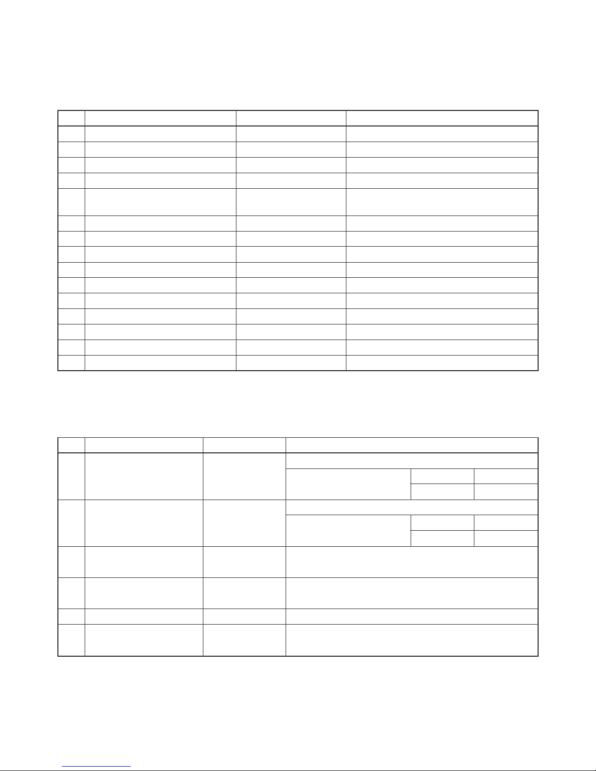
4. SPECIFICATION OF ELECTRICAL PARTS
4-1. Indoor Unit (RAS-13UKHP-E, RAS-10UKHP-E, RAS-07UKHP-E)
No. Parts name Type Specifications
1 Fan motor (for indoor) MMF-240-20-4A-1 AC Motor with 135°C thermo fuse
2 Thermo sensor (TA-sensor) ——— 10kΩ at 25°C
3 Switching transformer (T01) SWT-47
4 Microcontroller unit (IC30) TMP87CM40AN
5 Heat exchanger sensor ——— 10kΩ at 25°C
(TC-sensor)
6 Line filter (L01) LC*SS11V-06270 27mH, 600mA
7 Bridge rectifier (DB01) D3SBA60 4A, 600V
8 Capacitor (C02) KMH400VSSN47M22S 47µF, 400V
9 Fuse (F01) TSCR6.3A T6.3A, 250VAC
10 Varistor (R21, R22) 15G561K 560V
11 Resistor (R01) RF-2TK5R6 5.6Ω, 2W
12 Louver motor MP24GA 12VDC
13 Relay (Comp., RY01) DI12D1 Rating 20A/AC250V, 12VDC
14 Relay (Fan, RY03) G5N-1A Rating 3A/AC250V, 12VDC
15 Relay (Solenoide, RY04) G5N-1A Rating 3A/AC250V, 12VDC
No. Parts name Type Specifications
Output (Rated) 1100W, 2poles, 1 phase, 220 – 240V, 50Hz
1 Compressor PH170T2-4L2 Winding resistance (Ω) C-R C-S
(at 20°C) 2.22 3.04
Output (Rated) 42W, 6poles, 1 phase, 220 – 240V, 50/60Hz
2 Fan motor (for outdoor) HF-240-42B Winding resistance (Ω) Red-Black White-Black
(at 20°C) 176.2 290.5
3
Running capacitor
SK-50FMP1.5U2 AC 500V, 1.5µF
(for fan motor)
4
Running capacitor
DS371356CPN AC 370V, 35µF
(for compressor)
5 Overload relay JMRA99257-9200 U/T: 8.0A (80°C), OPEN: 145±5°C, CLOSE: 75±11°C
6
Solenoid coil
LB6409 AC 220 – 240V
(for 4-way valve)
4-2. Outdoor Unit (RAS-13UAH-E)
– 13 –
FILE NO. SVM-02001
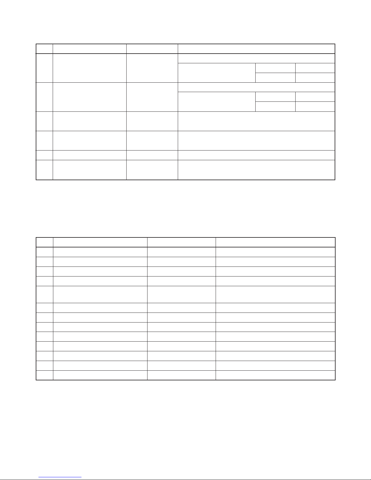
4-3. Outdoor Unit (RAS-10UAH-E)
No. Parts name Type Specifications
Output (Rated) 750W, 2poles, 1 phase, 220 – 240V, 50Hz
1 Compressor PH120T1-4C Winding resistance (Ω) C-R C-S
(at 20°C) 4.53 8.73
Output (Rated) 20W, 6poles, 1 phase, 220 – 240V, 50/60Hz
2 Fan motor (for outdoor) HF-240-20B Winding resistance (Ω) Red-Black White-Black
(at 20°C) 387.3 466.2
3
Running capacitor
SK-50FMP1.5U2 AC 500V, 1.5µF
(for fan motor)
4
Running capacitor
DS371256CPNB AC 370V, 25µF
(for compressor)
5 Overload relay JMRA99269-9200 U/T: 6.8A (90°C), OPEN: 135±5°C, CLOSE: 69±11°C
6
Solenoid coil
VH7100D AC 220 – 240V
(for 4-way valve)
4-4. Indoor Unit (RAS-13UKP-E, RAS-13UKPX, RAS-10UKP-E, RAS-10UKPX,
RAS-07UKP-E, RAS-07UKPX)
No. Parts name Type Specifications
1 Fan motor (for indoor) MMF-240-20-4A-1 AC Motor with 135°C thermo fuse
2 Thermo sensor (TA-sensor) ——— 10kΩ at 25°C
3 Switching transformer (T01) SWT-47
4 Microcontroller unit (IC30) TMP87CM40AN-2C67
5 Heat exchanger sensor ——— 10kΩ at 25°C
(TC-sensor)
6 Line filter (L01) LC*SS11V-06270 27mH, 600mA
7 Bridge rectifier (DB01) D3SBA60 4A, 600V
8 Capacitor (C02) KMH400VSSN47M22S 47µF, 400V
9 Fuse (F01) TSCR6.3A T6.3A, 250VAC
10 Varistor (R21, R22) 15G561K 560V
11 Resistor (R01) RF-2TK5R6 5.6Ω, 2W
12 Louver motor MP24GA 12VDC
13 Relay (Comp., RY01) DI12D1 Rating 20A/AC250V, 12VDC
– 14 –
FILE NO. SVM-02001
4-6. Outdoor Unit (RAS-10UA-E, RAS-10UAX-1)
No. Parts name Type Specifications
Output (Rated) 750W, 2poles,1 phase, 220 – 240V, 50Hz
Winding resistance (Ω) C-R C-S
(at 20°C) 3.60 4.87
Output (Rated) 750W, 2poles, 1 phase, 220 – 240V, 50Hz
Winding resistance (Ω) C-R C-S
(at 20°C) 3.88 5.06
Output (Rated) 20W, 6poles, 1 phase, 220 – 240V, 50Hz
2 Fan motor (for outdoor) HF-240-20B Winding resistance (Ω) Red-Black White-Black
(at 20°C) 387.3 466.2
SK-50FMP1.5U2
AC 500V, 1.5µF
3
Running capacitor (RAS-10UA-E)
(for fan motor) DS501155BPQA
AC 500V, 1.5µF
(RAS-10UAX-1)
4
Running capacitor
DS371256CPNB AC 370V, 25µF
(for compressor)
5 Overload relay LPA960B U/T: 6.1A (80°C), OPEN: 135±5°C, CLOSE: 78±11°C
1 Compressor
2PS146D5AB02
(RAS-10UA-E)
PH102T1-4C
(RAS-10UAX-1)
No. Parts name Type Specifications
Output (Rated) 1100W, 2poles, 1 phase, 220 – 240V, 50Hz
1 Compressor PH160T2-4L2 Winding resistance (Ω) C-R C-S
(at 20°C) 2.43 3.78
Output (Rated) 30W, 6poles, 1 phase, 220 – 240V, 50/60Hz
2 Fan motor (for outdoor) HF-240-30B Winding resistance (Ω) Red-Black White-Black
(at 20°C) 245 388
3
Running capacitor
SK-50FMP1.5U2 AC 500V, 1.5µF
(for fan motor)
4
Running capacitor
DS371356CPNB AC 370V, 35µF
(for compressor)
5 Overload relay LAAO00A U/T: 9.0A (80°C), OPEN: 135±5°C, CLOSE: 75±11°C
4-5. Outdoor Unit (RAS-13UA-E, RAS-13UAX)
– 15 –
FILE NO. SVM-02001
Standard 1.74 43.0 High 20/– 7/6
Heating Overload*1 1.9 ~ 2.3 52.0 ~ 59.0 Low 27/– 24/18
Low temperature 1.3 35.0 High 20/– –10/–10
Standard 0.45 10.0 High 27/19 35/24
Cooling Overload 0.58 14.0 High 32/23 43/26
Low temperature 0.4 2.0 Low 21/15 21/15
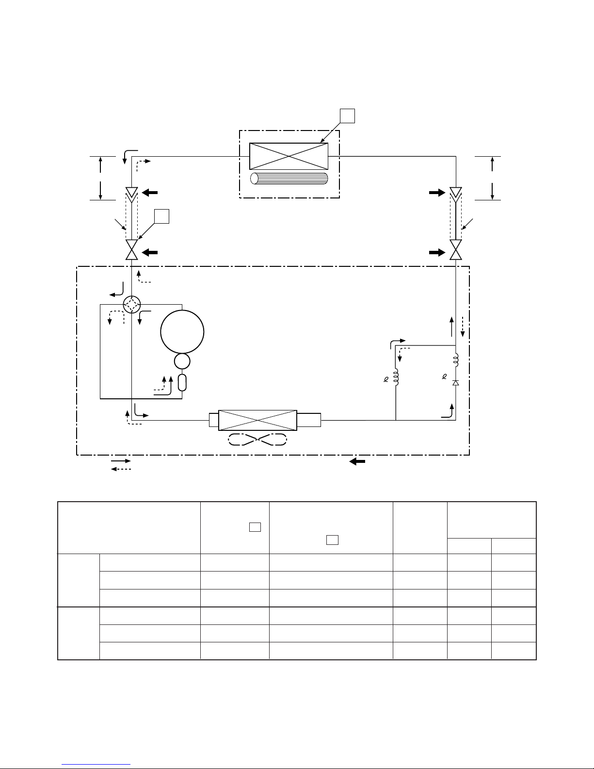
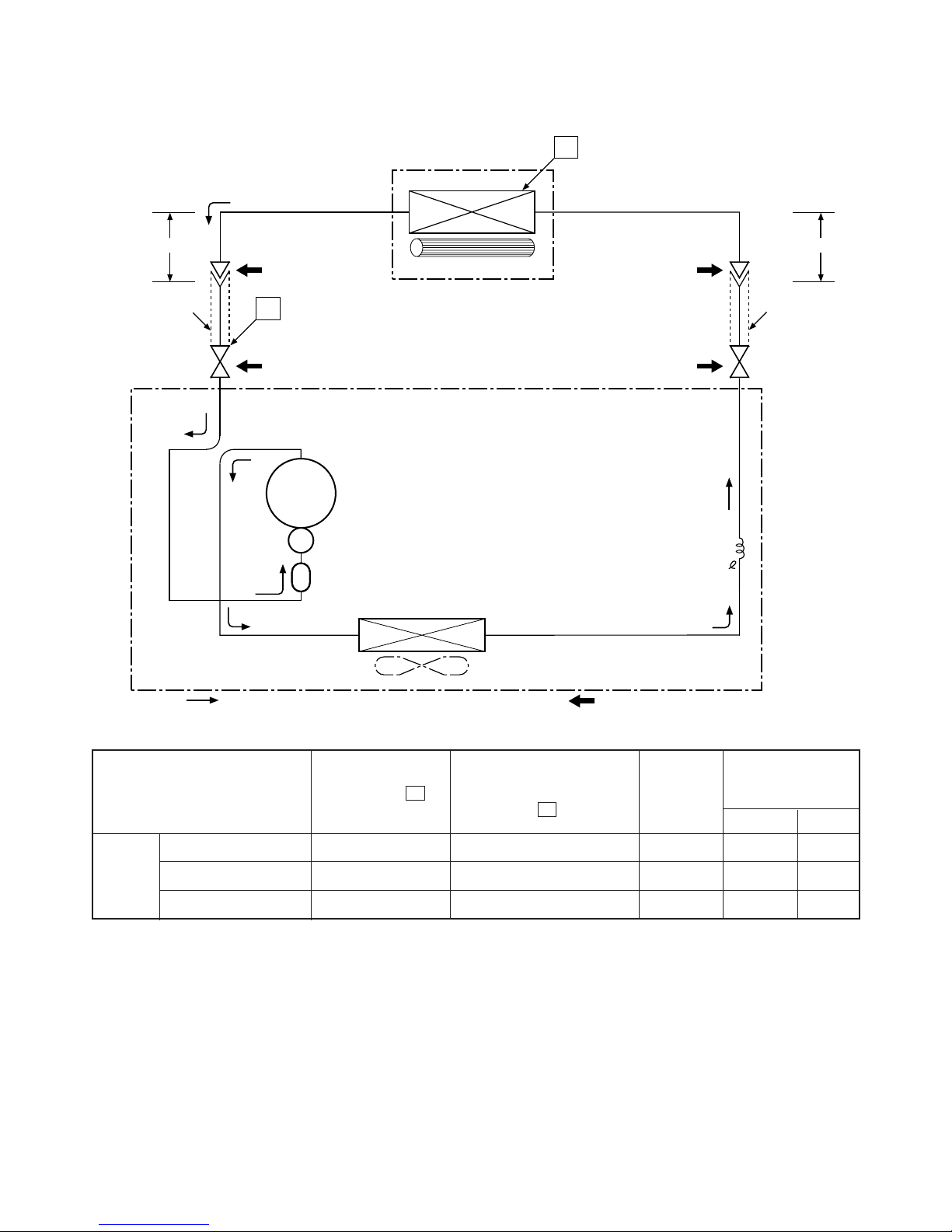
5. REFRIGERATION CYCLE DIAGRAM
5-1. RAS-13UKHP-E / RAS-13UAH-E
Note :
• Measure the heat exchanger temperature at the center of U-bend. (By means of TC sensor)
*1 • During heating overload operation, a value for the high temperature limit control operation is included.
50Hz
Standard
pressure P
(MPaG)
Surface temp. of heat
exchanger interchanging
pipe T1 (°C)
Fan speed
(indoor)
Ambient temp.
conditions DB/WB
(°C)
Indoor Outdoor
Evaporator
Indoor unit
Cross flow fan
Cooling
Heating
4-way valve
Heating
Cooling
Compressor
Accumulator
Condenser
Propeller fan
Outdoor unit
Capillary tube
Capillary tube
PH170T2-4L2
Cooling
Heating
Mark( )means check points of Gas Leak.
O.D.:12.7mm O.D.:6.35mm
Cooling
Heating
Packed valve
Packed valve
0.39m
(Connecting pipe)
0.49m
(Connecting pipe)
T1
P
Refrigerant
R22 : 1.10 kg.
∅1.0x800
∅1.7x1200
(∅12.7)
(∅6.35)
∅12.7
∅6.35
– 16 –
FILE NO. SVM-02001
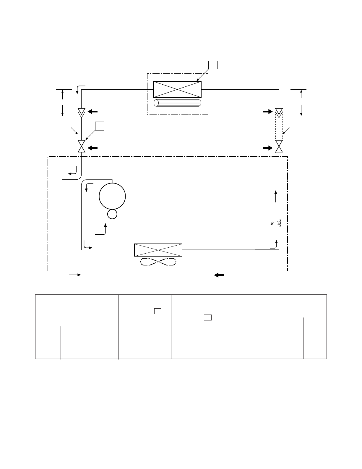
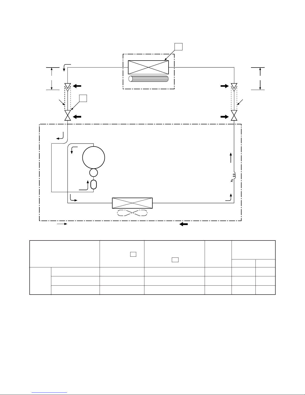
5-2. RAS-13UKP-E / RAS-13UA-E
RAS-13UKPX / RAS-13UAX
Note :
• Measure the heat exchanger temperature at the center of U-bend. (By means of TC sensor)
Cooling
Standard 0.45 13.0 High 27/19 35/24
Overload 0.62 18.0 High 32/23 43/26
Low temperature 0.40 2.0 Low 21/15 21/15
50Hz
Fan speed
(indoor)
Ambient temp.
conditions DB/WB
(°C)
Indoor Outdoor
Standard
pressure P
(MPaG)
Surface temp. of heat
exchanger interchanging
pipe T1 (°C)
Heat exchanger
Indoor unit
Cross flow fan
Cooling
Cooling
Compressor
Condenser
Propeller fan
Outdoor unit
Capillary tube
∅1.7x700
PH160T2-4L2
Cooling
Mark( )means check points of Gas Leak.
O.D.:12.7mm O.D.:6.35mm
Cooling
Packed valve
(∅12.7)
Packed valve
(∅6.35)
0.39m
(Connecting pipe)
∅12.7
0.49m
(Connecting pipe)
∅6.35
T1
P
Refrigerant
R-22 : 0.78 kg.
– 17 –
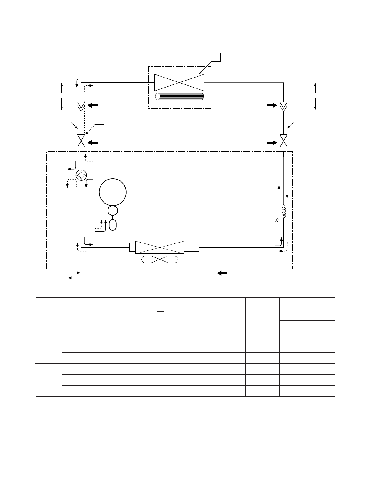
FILE NO. SVM-02001
5-3. RAS-10UKHP-E / RAS-10UAH-E
Indoor unit
Cross flow fan
Cooling
Heating
4-way valve
Heating
Cooling
Compressor
Condenser
Propeller fan
Outdoor unit
PH120T1-4C
Cooling
Heating
Mark( )means check points of Gas Leak.
O.D.:9.52mm O.D.:6.35mm
Cooling
Heating
Packed valve
(∅9.52)
Packed valve
(∅6.35)
0.39m
(Connecting pipe)
∅9.52
0.49m
(Connecting pipe)
∅6.35
T1
P
Refrigerant
R-22 : 0.74 kg.
Capillary tube
∅1.7x1600
Accumulator
Evaporator
Standard 1.55 40.0 High 20/– 7/6
Heating Overload*1 1.9 ~ 2.1 52.0 ~ 59.0 Low 27/– 24/18
Low temperature 1.3 35.0 High 20/––10/–10
Standard 1.94 12.0 High 27/19 35/24
Cooling Overload 2.50 15.0 High 32/23 43/26
Low temperature 0.32 2.0 Low 21/15 21/15
Note :
• Measure the heat exchanger temperature at the center of U-bend. (By means of TC sensor)
*1 • During heating overload operation, a value for the high temperature limit control operation is included.
50Hz
Standard
pressure P
(MPaG)
Surface temp. of heat
exchanger interchanging
pipe T1 (°C)
Fan speed
(indoor)
Ambient temp.
conditions DB/WB
(°C)
Indoor Outdoor
– 18 –
FILE NO. SVM-02001
5-4. RAS-10UKP-E / RAS-10UA-E
Note :
• Measure the heat exchanger temperature at the center of U-bend. (By means of TC sensor)
Cooling
Standard 0.54 13.0 High 27/19 35/24
Overload 0.62 18.0 High 32/23 43/26
Low temperature 0.38 2.0 Low 21/15 21/15
50Hz
Fan speed
(indoor)
Ambient temp.
conditions DB/WB
(°C)
Indoor Outdoor
Standard
pressure P
(MPaG)
Surface temp. of heat
exchanger interchanging
pipe T1 (°C)
Indoor unit
Cross flow fan
Cooling
Cooling
Compressor
Condenser
Propeller fan
Outdoor unit
2PS146D5AB02
Cooling
Mark( )means check points of Gas Leak.
O.D.:9.52mm O.D.:6.35mm
Cooling
Packed valve
(∅9.52)
Packed valve
(∅6.35)
0.39m
(Connecting pipe)
∅9.52
0.49m
(Connecting pipe)
∅6.35
T1
P
Refrigerant
R22 : 0.70 kg.
Evaporator
AccumulatorAccumulator
Capillary tube
∅1.5x1100
– 19 –
FILE NO. SVM-02001
5-5. RAS-10UKPX / RAS-10UAX-1
Note :
• Measure the heat exchanger temperature at the center of U-bend. (By means of TC sensor)
Cooling
Standard 0.55 13.0 High 27/19 35/24
Overload 0.63 18.0 High 32/23 43/26
Low temperature 0.39 2.0 Low 21/15 21/15
50Hz
Fan speed
(indoor)
Ambient temp.
conditions DB/WB
(°C)
Indoor Outdoor
Standard
pressure P
(MPaG)
Surface temp. of heat
exchanger interchanging
pipe T1 (°C)
Indoor unit
Cross flow fan
Cooling
Cooling
Compressor
Condenser
Propeller fan
Outdoor unit
PH102T1-4C
Cooling
Mark( )means check points of Gas Leak.
O.D.:9.52mm O.D.:6.35mm
Cooling
Packed valve
(∅9.52)
Packed valve
(∅6.35)
0.39m
(Connecting pipe)
∅9.52
0.49m
(Connecting pipe)
∅6.35
T1
P
Refrigerant
R-22 : 0.74 kg.
Evaporator
AccumulatorAccumulator
Capillary tube
∅1.5x1200
– 20 –
FILE NO. SVM-02001
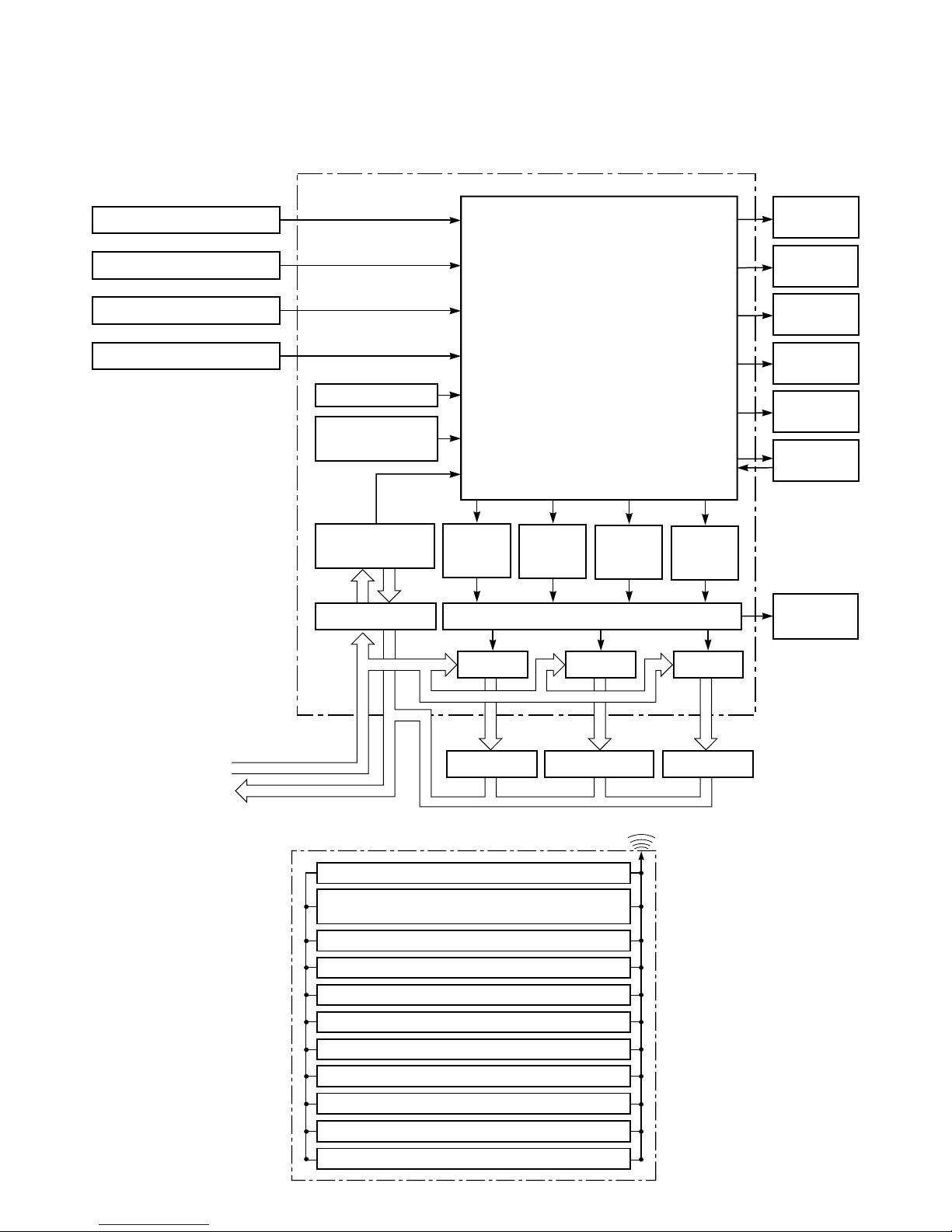
6. CONTROL BLOCK DIAGRAM
6-1. RAS-13UKHP-E / RAS-13UAH-E, RAS-10UKHP-E / RAS-10UAH-E,
RAS-07UKHP-E / RAS-07UAH-E
Heat Exchanger Sensor
Thermo. Sensor
Infrared Rays Signal Receiver
Initiallizing Circuit
Clock Frequency
Oscillator Circuit
Power Supply
Circuit
Noise Filter
220-240 V~, 50Hz
Functions
• Louver Control
• 3-minutes Delay at Restart for
Compressor
• Motor Revolution Control
• Processing
(Temperature Processing)
• Timer
Louver
ON/OFF
Signal
Relay Driver, Louver Driver
Operation
Display
Timer
Display
Filter Sign
Display
PRE DEF.
Sign Display
Indoor Fan
Motor
Hi Power
Sign Display
Louver
Motor
M.C.U.Main Unit Control Panel
Compressor
ON/OFF
Signal
Outdoor Fan
ON/OFF
Signal
4-Way Valve
ON/OFF
Signal
Relay Relay Relay
Compressor
Outdoor Fan Motor
4-Way Valve
Remote Control
Operation (START/STOP)
Operation Mode Selection
AUTO, COOL, DRY, HEAT, FAN ONLY
Temperature Setting
Fan Speed Selection
ON TIMER Setting
OFF TIMER Setting
Louver Auto Swing
Louver Direction Setting
ECO
Hi power
Filter Reset
REMOTE CONTROL
Infrared Rays
RY01 RY03 RY04
Current Sensor
(Compressor Current)
– 21 –
FILE NO. SVM-02001
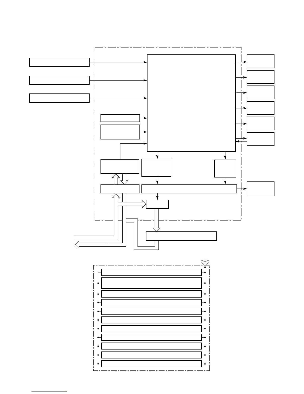
6-2. RAS-13UKP-E / RAS-13UA-E, RAS-10UKP-E / RAS10UA-E, RAS-07UKP-E / RAS-07UA-E
RAS-13UKPX / RAS-13UAX, RAS-10UKPX / RAS-10UAX-1, RAS-07UKPX / RAS-07UAX-1
Remote Control
Operation (START/STOP)
Operation Mode Selection
AUTO, COOL, DRY, FAN ONLY
Temperature Setting
Fan Speed Selection
ON TIMER Setting
OFF TIMER Setting
Louver Auto Swing
Louver Direction Setting
ECO
Hi power
Filter Reset
Infrared Rays
REMOTE CONTROL
Heat Exchanger Sensor
Thermo. Sensor
Infrared Rays Signal Receiver
Initiallizing Circuit
Clock Frequency
Oscillator Circuit
Power Supply
Circuit
Noise Filter
Louver
ON/OFF
Signal
Relay Driver, Louver Driver
Compressor, Outdoor Fan Motor
Operation
Display
Timer
Display
Filter Sign
Display
Fan Only
Sign Display
Indoor Fan
Motor
Hi Power
Sign Display
Louver
Motor
Compressor
ON/OFF
Signal
Functions
• Louver Control
• 3-minutes Delay at Restart for
Compressor
• Motor Revolution Control
• Processing
(Temperature Processing)
• Timer
Main Unit Control Panel M.C.U.
RY01
Relay
220-240 V~, 50Hz
– 22 –
FILE NO. SVM-02001
7. OPERATION DESCRIPTION
7-1-1. Louver Control
(1) Vertical air flow louver
Position of veritcal air flow louver is automatically
controlled according to the operation mode.
Besides, position of vertical air flow louver can be
arbitrarily set by pressing [FIX] button.
The louver position which is set by [FIX] button is
stored in the microcontroller, and the louver is
automatically set at the stored position for the next
operation.
(2) Swing
If [SWING] button is pressed when the indoor unit
is in operation, the vertical air flow louver starts
swinging. When [FIX] button is pressed, it stops
swinging.
7-1-2. Indoor Fan Control (AC Fan Motor)
(1) The indoor fan is operated by the stepless speed
change AC motor.
(2) For air flow level, speed of the indoor fan motor is
controlled in five steps (LOW, LOW
+
, MED, MED
+
and HIGH). If AUTO mode is selected, the fan
motor speed is automatically controlled by the
difference between the preset temperature and
the room temperature.
Table 7-1-1
RAS-07UKHP-E RAS-10UKHP-E RAS-13UKHP-E
Model Motor speed Air flow level Motor speed Air flow level Motor speed Air flow level
(rpm) (m3/h) (rpm) (m3/h) (rpm) (m3/h)
HIGH 1,200 570 1,200 570 1,300 630
Cooling MED+ 1,100 520 1,100 520 1,200 570
and MED 1,000 460 1,000 460 1,100 520
Fan only LOW+ 900 400 900 400 1,020 470
LOW 800 340 800 340 950 430
HIGH 1,250 610 1,250 610 1,350 650
MED+ 1,150 550 1,170 560 1,250 610
Heating MED 1,050 490 1,100 520 1,150 550
LOW+ 980 450 1,000 460 1,100 520
LOW 900 400 900 400 1,050 490
Model
RAS-07UKP-E RAS-10UKP-E RAS-13UKP-E
RAS-07UKPX RAS-10UKPX RAS-13UKPX
HIGH 1,200 570 1,300 630 1,300 630
Cooling MED+ 1,100 520 1,180 560 1,220 600
and MED 1,000 460 1,050 490 1,150 550
Fan only LOW+ 900 400 950 430 1,070 500
LOW 800 340 850 370 1,000 460
7-1. Outline of Air Conditioner Control
This is a fixed capacity type air conditioner, which uses
a AC motor for an indoor fan. The AC motor drive
circuit is mounted in the indoor unit. And electrical
parts which operate the compressor and the outdoor
fan motor, are mounted in the outdoor unit.
The air conditioner is mainly controlled by the indoor
unit controller. The controller operates the indoor fan
motor based upon commands transmitted by the
remote control and transfers the operation commands
to the outdoor unit controller.
The outdoor unit controller receives operation
commands from the indoor unit, and operates the
outdoor fan motor and the compressor.
(1) Role of indoor unit controller
The indoor unit controller receives the operation
commands from the remote control and executes
them.
• Temperature measurement at the air inlet of the
indoor heat exchanger by the indoor temperature sensor
• Temperature setting of the indoor heat exchanger
by the heat exchanger sensor
• Louver motor control
• Indoor fan motor operation control
• LED display control
• Transferring of operation commands to the
outdoor unit
• Receiving of information of the operation status
and judging of the information or indication of
error
LOW+=
MED+=
LOW+MED
2
MED+HIGH
2
– 23 –
FILE NO. SVM-02001
7-2. Description of Operation Circuit
(1) When turning on the breaker, the operation lamp
blinks. This means that the power is on (or the
power supply is cut off.)
(2) When pressing [START / STOP] button on the
remote control, receiving beep sounds from the
indoor unit, and the next operation is performed
together with opening the vertical air flow louver.
(3) Once the operation mode is set, it is memorized in
the microcontroller so that the previous operation
can be effected thereafter simply by pressing
[START / STOP] button.
7-2-1. Fan Only Operation
([MODE] button on the remote control is set
to the fan only operation.)
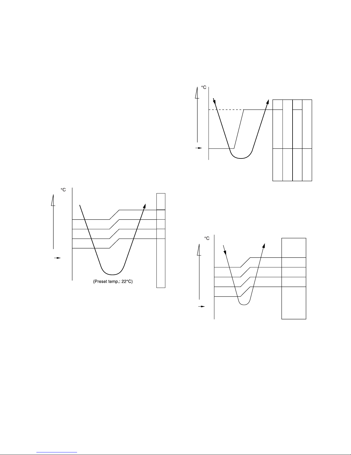
(1) When [FAN] button is set to AUTO, the indoor fan
motor operates as shown in Fig. 7-2-1. When
[FAN] button is set to LOW, LOW
+
, MED, MED+ or
HIGH, the motor operates with a constant air flow.
NOTE :
*1: The values marked with *1 are calculated and
controlled by the difference in motor speed
between M+ and L–.
Fig. 7-2-1 Setting of air flow [FAN:AUTO]
(2) The Hi POWER operation cannot be set.
7-2-2. Cooling Operation
([MODE] button on the remote control is set
to the cooling operation.)
(1) The compressor, 4-way valve, outdoor fan and
operation display on the remote control are
controlled as shown in Fig. 7-2-2.
Fig. 7-2-2
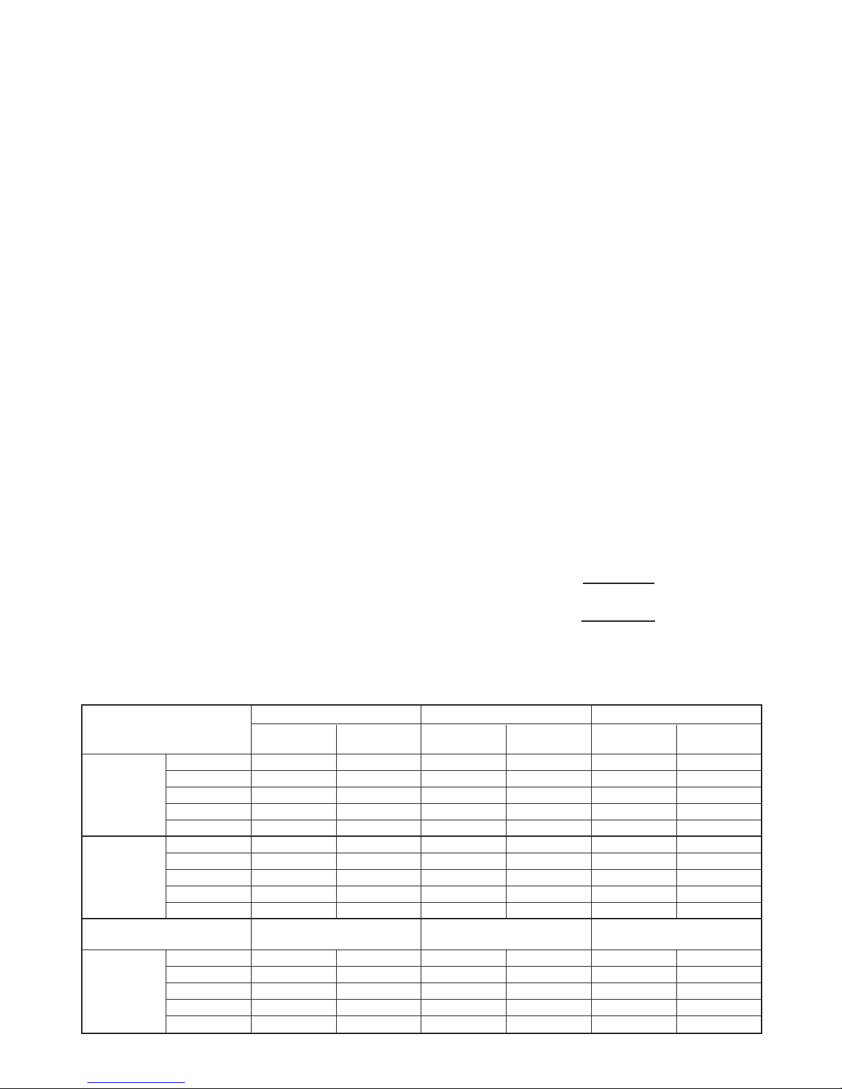
(2) When [FAN] button is set to AUTO, the indoor fan
motor operates as shown in Fig. 7-2-3. When
[FAN] button is set to LOW, LOW+, MED, MED+ or
HIGH, the motor operates with a constant air flow.
NOTE :
*1: The values marked with *1 are calculated and
controlled by the difference in motor speed
between M+ and L–.
Fig. 7-2-3 Setting of air flow [FAN:AUTO]
+2
+2.5
+3
+1.5
+1
+0.5
0
M+
*1
*1
*1
L–
(Room temp.) – (Preset temp.)
Preset
temp.
*1
*1
*1
L–
+3
+2.5
+2
+1.5
+1
+0.5
-0.5
0
M+
(Room temp.) – (Preset temp.)
Preset
temp.
0.5
0
Preset
temp.
ON ON
OFF OFF OFF ON
Compressor
4-way valve
Outdoor fan
OPERATION
display
(Room temp.) — (Preset temp.)
 Loading...