

Toshiba RAS-M18SAH-E, RAS-10SKH-E-1, RAS-10SKH-E-1 x 2, RAS-13SKH-E, RAS-3M31SAH-E-1 Service Manual
...
PRINTED IN JAPAN, Apr.,1998 ToMo
SERVICE MANUAL
FILE NO. A00-9805
AIR-CONDITIONER
MULTI SPLIT WALL TYPE
SUPPLEMENT
RAS-10SKH-E-1
x 2 /
RAS-M18SAH-E
RAS-10SKH-E-1
x
2, RAS-13SKH-E
/
RAS-3M31SAH-E-1
RAS-10SKH-E-1
x 4 /
RAS-4M36SAH-E
x 2 x 3 x 4

– 2 –
CONTENTS
1. DESCRIPTION .................................................................................................................3
2. SPECIFICATIONS............................................................................................................ 4
3. CONSTRUCTION VIEWS .............................................................................................. 11
3-1. Indoor Unit ................................................................................................................................ 11
3-2. Outdoor Unit ............................................................................................................................. 12
4. REFRIGERANT CYCLE DIAGRAMS ............................................................................ 14
5. WIRING DIAGRAM ........................................................................................................ 17
6. SPECIFICATIONS OF ELECTRICAL PARTS ............................................................... 19
6-1. Indoor Unit ................................................................................................................................ 19
6-2. Outdoor Unit ............................................................................................................................. 20
7. MICROCOMPUTER BLOCK DIAGRAMS ..................................................................... 21
8. OPERATION DESCRIPTIONS....................................................................................... 23
8-1. FAN ONLY Operation ............................................................................................................... 23
8-2. COOL Operation....................................................................................................................... 23
8-3. DRY Operation.......................................................................................................................... 24
8-4. HEAT Operation........................................................................................................................ 25
8-5. AUTO Operation ....................................................................................................................... 26
8-6. ECONO. Mode ........................................................................................................................... 27
8-7. Current Limit Control............................................................................................................... 27
8-8. High-Temperature Limit Control............................................................................................. 28
8-9. Low-Temperature Limit Control (Cooling Operation) .......................................................... 28
8-10. Cool Airflow Prevention Control (Heating Operation) ......................................................... 29
8-11. Defrost Operation..................................................................................................................... 29
8-12. Auto Restart Function ............................................................................................................. 3 1
8-13. Operation Control of Following Outdoor Unit....................................................................... 33
9. TROUBLESHOOTING CHART ...................................................................................... 34
9-1. What to be Prechecked First................................................................................................... 3 4
9-2. Primary Judgement of Trouble Sources ................................................................................ 36
9-3. Troubleshooting Flowcharts ................................................................................................... 40
9-4. How to Check the Remote Control (Including the Indoor P.C. Board) ............................... 47
10. PART REPLACEMENT.................................................................................................. 52
10-1. Indoor Unit ................................................................................................................................ 5 2
10-2. Microcomputer ......................................................................................................................... 54
10-3. Outdoor Unit ............................................................................................................................. 55
11. CAUTIONS ON REPLACEMENT OF P.C. BOARD ASSEMBLY ................................... 64
12. EXPLODED VIEWS AND PARTS LIST ......................................................................... 65
12-1. Indoor Unit (1) ........................................................................................................................... 65
Indoor Unit (2)........................................................................................................................... 66
Indoor Unit (3)........................................................................................................................... 67
12-2. Outdoor Unit ............................................................................................................................. 68

– 3 –
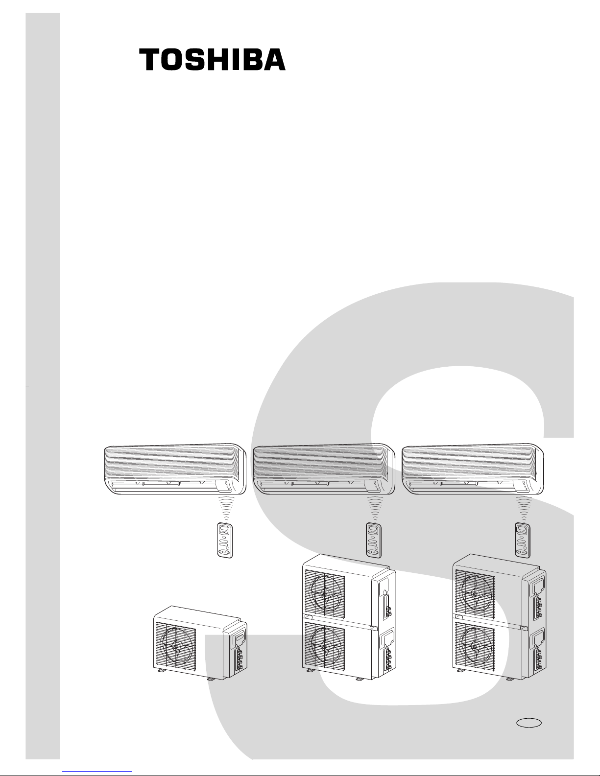
1. DESCRIPTION
RAS-M18SAH-E
RAS-M18SAH-E can be used alone with two indoor units RAS-10SKH-E-1.
RAS-3M31SAH-E-1
in a combination of two outdoor units
RAS-13SAH-E (upper unit, one compressor)
RAS-M18SAH-E (lower unit, two compressors)
The upper unit can be used with one indoor unit RAS-13SKH-E and the lower
unit with two indoor units RAS-10SKH-E-1.
RAS-4M36SAH-E
The lower unit RAS-M18SAH-E can be used as a double decker under the
combination name RAS-4M36SAH-E with four indoor units RAS-10SKH-E-1.
– 4 –
2. SPECIFICATIONS
RAS-10SKH-E-1 x 2 / RAS-M18SAH-E
Model
Item
Capacity *1 kW
Phase
Power source V
Hz
Power consumption kW
Power factor %
Running current
A
Indoor/Outdoor
Starting current A
Moisture removal lit/h
Noise
Indoor (H/M/L) dB
Outdoor (220/230/240V) dB
Refrigerant
Name of refrigerant
Rated volume kg
Refrigerant control
Gas side size mm
Connection type
Liquid side size mm
Interconnection pipe
Connection type
Maximum length (One way) m *2
Maximum height difference
Indoor unit
m
Outdoor unit
Condensate drain pipe Outer diameter mm
INDOOR UNIT
Height mm
Dimensions Width mm
Depth mm
Net weight kg
Evaporator type
Indoor fan type
High fan m3/h
Air volume Medium fan m3/h
Low fan m3/h
Fan motor output W
Air filter
OUTDOOR UNIT
Height mm
Dimensions Width mm
Depth mm
Net weight kg
Condenser type
Outdoor fan type
Airflow volume (220/230/240V) m3/h
Fan motor output W
Compressor Model
Output W
Safety device
Auto louver
Usable outdoor temperature range °C
RAS-10SKH-E-1 x 2 / RAS-M18SAH-E
Cooling Heating
220V 230V 240V 220V 230V 240V
5,0 5,0 5,0 5,6 5,6 5,6
Single
220/230/240
50
2,04/2,10/2,18 1,78/1,86/1,96
95/92/89 94/91/87
220V 230V 240V 220V 230V 240V
0,22/9,54 0,22/9,7 0,22/9,96 0,22/8,38 0,22/8,66 0,22/9,16
19
1,2
41/36/31
52/53/54
R-22
1,4 (0,7+0,7)
Capillary tube
9,52
Flare connection
6,35
Flare connection
15
5
16
RAS-10SKH-E-1
265
790
174
8
Finned tube
Cross flow fan
600
500
400
19
Polypropylene net filter (Washable)
RAS-M18SAH-E
538
830
300
55
Finned tube
Propeller
1830/1920/2010
28
PH120T1-4C x 2
750W x 2
Fuse, Overload relay
Yes
21 ~ 43 – 5 ~ 21
Specifications are subject to change without notice.
– 5 –
RAS-10SKH-E-1 / RAS-M18SAH-E
Cooling Heating
220V 230V 240V 220V 230V 240V
2,50 2,50 2,50 2,80 2,80 2,80
Single
220/230/240
50
1,02/1,05/1,09 0,89/0,93/0,98
95/92/89 94/91/87
220V 230V 240V 220V 230V 240V
0,11/4,77 0,11/4,85 0,11/4,98 0,11/4,19 0,11/4,33 0,11/4,58
Model
Item
Capacity *1 kW
Phase
Power source V
Hz
Power consumption kW
Power factor %
Running current
A
Indoor/Outdoor

– 6 –
Model
Item
Capacity *1 kW
Phase
Power source V
Hz
Power consumption kW
Power factor %
Running current
A
Indoor/Outdoor
Starting current A
Moisture removal lit/h
Noise
Indoor (H/M/L) dB
Outdoor (220/230/240V) dB
Refrigerant
Name of refrigerant
Rated volume kg
Refrigerant control
Gas side size mm
Connection type
Liquid side size mm
Interconnection pipe
Connection type
Maximum length (One way) m *2
Maximum height difference
Indoor unit
m
Outdoor unit
Condensate drain pipe Outer diameter mm
INDOOR UNIT
Height mm
Dimensions Width mm
Depth mm
Net weight kg
Evaporator type
Indoor fan type
High fan m3/h
Air volume Medium fan m3/h
Low fan m3/h
Fan motor output W
Air filter
OUTDOOR UNIT
Height mm
Dimensions Width mm
Depth mm
Net weight kg
Condenser type
Outdoor fan type
Airflow volume (220/230/240V) m3/h
Fan motor output W
Compressor Model
Output W
Safety device
Auto louver
Usable outdoor temperature range °C
RAS-10SKH-E-1 x 2, RAS-13SKH-E / RAS-3M31SAH-E-1
Specifications are subject to change without notice.
RAS-10SKH-E-1 x 2, RAS-13SKH-E / RAS-3M31SAH-E-1
Cooling Heating
220V 230V 240V 220V 230V 240V
8,45 8,50 8,50 9,60 9,65 9,70
Single
220/230/240
50
3,30/3,38/3,48 2,97/3,09/3,23
96/93/90 94/93/89
220V 230V 240V 220V 230V 240V
0,37/15,24 0,37/15,36 0,37/15,71 0,37/13,92 0,37/14,14 0,37/14,70
19+19+25
1,2+1,2+2,0
RAS-10SKH-E-1 : 41/36/31 RAS-13SKH-E : 44/39/36
52/53/54
R-22
2,28 (0,7+0,7+0,88)
Capillary tube
RAS-10SKH-E-1 : 9,52 RAS-13SKH-E : 12,7
Flare connection
6,35
Flare connection
15
RAS-10SKH-E-1 : 5 RAS-13SKH-E : 6
16
RAS-10SKH-E-1 RAS-13SKH-E
265
790
174
8
Finned tube
Cross flow fan
600 650
500 560
400 510
19
Polypropylene net filter (Washable)
RAS-3M31SAH-E-1
1125
830
300
106
Finned tube
Propeller
1830/1920/2010
28
PH120T1-4C x 2 + PH170T2-4L2
750W x 2 + 1100W x 1
Fuse, Overload relay
Yes
21 ~ 43 – 5 ~ 21

– 7 –
RAS-10SKH-E-1, RAS-13SKH-E / RAS-3M31SAH-E-1
Cooling Heating
220V 230V 240V 220V 230V 240V
5,95 6,00 6,00 6,80 6,85 6,90
Single
220/230/240
50
2,28/2,33/2,39 2,08/2,16/2,25
97/94/91 95/93/90
220V 230V 240V 220V 230V 240V
0,26/10,47 0,26/10,51 0,26/10,73 0,26/9,73 0,26/9,81 0,26/10,12
RAS-10SKH-E-1 x 2 / RAS-3M31SAH-E-1
Cooling Heating
220V 230V 240V 220V 230V 240V
5,0 5,0 5,0 5,6 5,6 5,6
Single
220/230/240
50
2,04/2,10/2,18 1,78/1,86/1,96
95/92/89 94/91/87
220V 230V 240V 220V 230V 240V
0,22/9,54 0,22/9,70 0,22/9,96 0,22/8,38 0,22/8,66 0,22/9,16
RAS-13SKH-E / RAS-3M31SAH-E-1
Cooling Heating
220V 230V 240V 220V 230V 240V
3,45 3,50 3,50 4,00 4,05 4,10
Single
220/230/240
50
1,26/1,28/1,30 1,19/1,23/1,27
98/96/92 95/95/93
220V 230V 240V 220V 230V 240V
0,15/5,70 0,15/5,66 0,15/5,75 0,15/5,54 0,15/5,48 0,15/5,54
RAS-10SKH-E-1 / RAS-3M31SAH-E-1
Cooling Heating
220V 230V 240V 220V 230V 240V
2,50 2,50 2,50 2,80 2,80 2,80
Single
220/230/240
50
1,02/1,05/1,09 0,89/0,93/0,98
95/92/89 94/91/87
220V 230V 240V 220V 230V 240V
0,11/4,77 0,11/4,85 0,11/4,98 0,11/4,19 0,11/4,33 0,11/4,58
Model
Item
Capacity *1 kW
Phase
Power source V
Hz
Power consumption kW
Power factor %
Running current
A
Indoor/Outdoor
Model
Item
Capacity *1 kW
Phase
Power source V
Hz
Power consumption kW
Power factor %
Running current
A
Indoor/Outdoor
Model
Item
Capacity *1 kW
Phase
Power source V
Hz
Power consumption kW
Power factor %
Running current
A
Indoor/Outdoor
Model
Item
Capacity *1 kW
Phase
Power source V
Hz
Power consumption kW
Power factor %
Running current
A
Indoor/Outdoor
– 8 –
Specifications are subject to change without notice.
Model
Item
Capacity *1 kW
Phase
Power source V
Hz
Power consumption kW
Power factor %
Running current
A
Indoor/Outdoor
Starting current A
Moisture removal lit/h
Noise
Indoor (H/M/L) dB
Outdoor (220/230/240V) dB
Refrigerant
Name of refrigerant
Rated volume kg
Refrigerant control
Gas side size mm
Connection type
Liquid side size mm
Interconnection pipe
Connection type
Maximum length (One way) m *2
Maximum height difference
Indoor unit
m
Outdoor unit
Condensate drain pipe Outer diameter mm
INDOOR UNIT
Height mm
Dimensions Width mm
Depth mm
Net weight kg
Evaporator type
Indoor fan type
High fan m3/h
Air volume Medium fan m3/h
Low fan m3/h
Fan motor output W
Air filter
OUTDOOR UNIT
Height mm
Dimensions Width mm
Depth mm
Net weight kg
Condenser type
Outdoor fan type
Airflow volume (220/230/240V) m3/h
Fan motor output W
Compressor Model
Output W
Safety device
Auto louver
Usable outdoor temperature range °C
RAS-10SKH-E-1 x 4 / RAS-4M36SAH-E
Cooling Heating
220V 230V 240V 220V 230V 240V
10,0 10,0 10,0 11,2 11,2 11,2
Single
220/230/240
50
4,08/4,20/4,36 3,56/3,72/3,92
95/92/89 94/91/87
220V 230V 240V 220V 230V 240V
0,44/19,08 0,44/19,4 0,44/19,92 0,44/16,76 0,44/17,32 0,44/18,32
19+19+19+19
1,2+1,2+1,2+1,2
41/36/31
54/55/56 55/56/57
R-22
2,8 (0,7+0,7+0,7+0,7)
Capillary tube
9,52
Flare connection
6,35
Flare connection
15
5
16
RAS-10SKH-E-1
265
790
174
8
Finned tube
Cross flow fan
600
500
400
19
Polypropylene net filter (Washable)
RAS-4M36SAH-E
1125
830
300
119
Finned tube
Propeller
1830/1920/2010
28
PH120T1-4C
750W x 4
Fuse, Overload relay
Yes
21 ~ 43 – 5 ~ 21
RAS-10SKH-E-1 x 4 / RAS-4M36SAH-E
– 9 –
RAS-10SKH-E-1 x 3 / RAS-4M36SAH-E
Cooling Heating
220V 230V 240V 220V 230V 240V
7,50 7,50 7,50 8,40 8,40 8,40
Single
220/230/240
50
3,06/3,15/3,27 2,67/2,79/2,94
97/94/91 95/93/90
220V 230V 240V 220V 230V 240V
0,33/14,31 0,33/14,55 0,33/14,94 0,33/12,57 0,33/12,99 0,33/13,74
RAS-10SKH-E-1 x 2 / RAS-M36SAH-E
Cooling Heating
220V 230V 240V 220V 230V 240V
5,0 5,0 5,0 5,6 5,6 5,6
Single
220/230/240
50
2,04/2,10/2,18 1,78/1,86/1,96
95/92/89 94/91/87
220V 230V 240V 220V 230V 240V
0,22/9,54 0,22/9,70 0,22/9,96 0,22/8,38 0,22/8,66 0,22/9,16
RAS-10SKH-E-1 / RAS-4M36SAH-E
Cooling Heating
220V 230V 240V 220V 230V 240V
2,50 2,50 2,50 2,80 2,80 2,80
Single
220/230/240
50
1,02/1,05/1,09 0,89/0,93/0,98
95/92/89 94/91/87
220V 230V 240V 220V 230V 240V
0,11/4,77 0,11/4,85 0,11/4,98 0,11/4,19 0,11/4,33 0,11/4,58
Model
Item
Capacity *1 kW
Phase
Power source V
Hz
Power consumption kW
Power factor %
Running current
A
Indoor/Outdoor
Model
Item
Capacity *1 kW
Phase
Power source V
Hz
Power consumption kW
Power factor %
Running current
A
Indoor/Outdoor
Model
Item
Capacity *1 kW
Phase
Power source V
Hz
Power consumption kW
Power factor %
Running current
A
Indoor/Outdoorr
– 10 –
Cooling
27°C
19°C
35°C
24°C
Heating
20°C
—
7°C
6°C
JIS C9612-1994Condition
(DB)
(WB)
(DB)
(WB)
T emperature
Indoor unit inlet air temperature
Outdoor unit inlet air temperature
Notes : *2
RAS-13SKH-E / RAS-3M31SAH-E-1
• No additional refrigerant required.
• This air conditioner accepts a connection piping length of up to 15m and a head of up to 6m.
• There is no need to add the refrigerant as long as the total length of the connection piping is up to 15m.
RAS-10SKH-E-1 / RAS-M18SAH-E,
RAS-10SKH-E-1 / RAS-3M31SAH-E-1,
RAS-10SKH-E-1 / RAS-4M36SAH-E
• This air conditioner accepts a connection piping length of up to 15m and a head of up to 5m.
• There is no need to add the refrigerant as long as the total length of the connection piping is up to 10m.
• There is need to add the refrigerant 20g/m as long as the each length of the connection piping is up to 11m to
15m.
Note : *1
• Capacity is based on the following temperature conditions .
– 11 –
3. CONSTRUCTION VIEWS
3-1. Indoor Unit
RAS-10SKH-E-1
RAS-13SKH-E
,,,,,,,,,,,,,,,,
,,,,,,,,,,,,,,,,
,,,,,,,,,,,,,,,,
,,,,,,,,,,,,,,,,
,,,,,,,,,,,,,,,,
,,,,,,,,,,,,,,,,
,,,,,,,,,,,,,,,,
,,,,,,,,,,,,,,,,
,,,,,,,,,,,,,,,,
,,,,,,,,,,,,,,,,
,,,,,,,,,,,,,,,,
,,,,,,,,,,,,,,,,
,,,,,,,,,,,,,,,,,
,,,,,,,,,,,,,,,,,
,,,,,,,,,,,,,,,,,
,,,,,,,,,,,,,,,,,
,,,,,,,,,,,,,,,,,
,,,,,,,,,,,,,,,,,
,,,,,,,,,,,,,,,,,
,,,,,,,,,,,,,,,,,
,,,,,,,,,,,,,,,,,
,,,,,,,,,,,,,,,,,
,,,,,,,,,,,,,,,,,
,,,,,,,,,,,,,,,,,
Air filter
790
Heat exchanger
Air inlet
265
Air outlet
47
10
50
174
47
10
50
Wireless
remote
control
55
16
559,6
Remote
control
holder
112,8
136
Knock out system
790
232 326 232
Hanger
321
Drain hose (0,54m)
Connecting pipe (0,39m)
(Flare ø6,35)
13SKH-E
: (Flare ø12,7)
10SKH-E-1: (Flare ø9,52)
Hanger
65965,5
326
450
65,5
For stud bolt
(ø8~ø10)
For stud bolt
(ø6)
Hanger
Minimum
distance to wall
Minimum
distance
to ceiling
265
Knock out system
Front panel
Back body
20 2037
40,5
60,5
790
12626931976
Center line
Installation
plate outline
HangerHanger
40,5
3,5
Hanger
Minimum
distance
to wall
17 20
46
120 or more 120 or more
66 or more
2,5
Connecting pipe (0,49m)
– 12 –
3-2. Outdoor Unit
RAS-M18SAH-E
325
23
301
325
325
538
54545491
100 or more
100 or more
600 or more
600 or more
Installation dimension
4x
φ
11x14
for
φ
8-
φ
10
anchor bolt
600
Air inlet
Air inlet
Air outlet
φ
11x14 hole
φ
6 hole
R10
600
Detail Drawing
50
36
300
90 600 90 50
830 60 344
A
6-
φ
11x14 hole
(for
φ
8-
φ
10 anchor bolt)
8-
φ
6 hole
(for fixing outdoor unit)
Liquid side
(Flare
φ
6,35)
Gas side
(Flare
φ
9,52)
A
Handle
φ
420
Fan guard
Electric
parts cover
Service
port
FOR UNIT B
FOR UNIT A
52
120
φ25 Drain outlet
– 13 –
RAS-3M31SAH-E-1
RAS-4M36SAH-E
325
23
52,5
311
325
325
54545491
100 or more
100 or more
600 or more
600 or more
Mounting dimension of anchor bolt
4-φ11x14
for φ8-φ10
anchor bolt
600
Air inlet
Air inlet
Air outlet
φ11x14 hole
φ 6 hole
R12
600
Detail Drawing
36
120
50
90
29
600 90 55
835 60 342
A
4-φ11x14 hole
(for φ8 φ10 anchor bolt)
8-φ6 hole
(for fixing outdoor unit)
φ25 Drain outlet
Liquid side
(Flare φ6,35)
Gas side
(Flare φ9,52)
A
Drain outlet
Electrical
parts cover
Handle
Service
port
Liquid side
(Flare φ6,35)
Gas side (Flare)
Electrical
parts cover
54677,5
1125
60
300
186
325 (pitch)(8,5) (8,5)
Service
port
Model name
RAS-3M31SAH-E-1
RAS-4M36SAH-E
Size
φ12,7
φ9,52
– 14 –
4. REFRIGERANT CYCLE DIAGRAMS
RAS-10SKH-E-1 x 2 / RAS-M18SAH-E
Note :
• Measure the heat exchanger temperature at the center of U-bend. (By means of TC sensor.)
*
1 • During heating overload, the high temperature limit control operation is included.
Surface temp. of heat
exchanger interchanging
pipe T1 (°C)
10SKH-E-1
40,0
52,0 ~ 59,0
35,0
12,0
15,0
2,0
Standard pressure
P
(kg/cm²G)
10SKH-E-1
15,0
19 ~ 23
12,5
6,0
6,5
4,0
Heating
Cooling
Ambient temp.
conditions DB/WB
(°C)
Fan speed
(indoor)
High
Low
High
High
High
Low
Indoor
20/–
27/–
20/–
27/19
32/23
21/15
Outdoor
7/6
21/15
–10/–10
35/24
43/26
21/15
50Hz
Standard
High temperature*1
Low temperature
Standard
High temperature
Low temperature
4-way valve
Accumulator
PH120T1-4C
Cooling
Heating
Dryer
Capillary
for heating
ø1,7x300
Capillary
for cooling & heating
ø1,7x800
Outdoor heat exchanger
Outdoor Unit
Packed valve Packed valve
(3/8) (1/4)
Indoor heat exchanger A
Indoor Unit
Check
valve
CompressorCompressor
PH120T1-4C
Indoor heat exchanger B
T1
P
– 15 –
RAS-10SKH-E-1 x 2, RAS-13SKH-E / RAS-3M31SAH-E-1 (Upper and Lower Unit)
Note :
• Measure the heat exchanger temperature at the center of U-bend. (By means of TC sensor.)
*
1 • During heating overload, the high temperature limit control operation is included.
Heating
Cooling
50Hz
Standard
High temperature*1
Low temperature
Standard
High temperature
Low temperature
Ambient temp.
conditions DB/WB
(°C)
Fan speed
(indoor)
High
Low
High
High
High
Low
Indoor
20/–
27/–
20/–
27/19
32/23
21/15
Outdoor
7/6
21/15
–10/–10
35/24
43/26
21/15
Standard pressure
P
(kg/cm²G)
13SKH-E
10SKH-E-1
15,0
19 ~ 23
12,5
5,0 6,0
6,0 6,5
4,0
Surface temp. of heat
exchanger interchanging
pipe T1 (°C)
13SKH-E 10SKH-E-1
43,0 40,0
52,0 ~ 59,0
35,0
10,0 12,0
14,0 15,0
2,0
Heat exchanger
RAS-13SKH-E
Indoor Unit
Cross flow fan
Gas container connection (Reinstall etc.)
Heating
4-way valve
Heating
Cooling
Accumulator
Heat exchanger
Propeller fan
Outdoor Unit
Capillary tube
ø1,2x400
Capillary tube
ø0,6x1500
Cooling
Cooling
Mark ( ) means check points of Gas Leak
O.D.:
12,7mm
O.D.:
6,35mm
Cooling
Heating
Packed valve
(ø12,7)
Packed valve
(ø6,35)
0,49m
(Connecting
pipe)
ø12,7
0,39m
(Connecting
pipe)
ø6,35
T1
P
Capillary tube
ø1,7x400
Heating
Refrigerant
R-22 0,88kg
PH170T2-4L2
4-way valve
Accumulator
Cooling
Heating
Dryer
Capillary
for heating
ø1,7x300
Capillary
for cooling
& heating
ø1,7x800
Outdoor heat
exchanger
Outdoor Unit
Packed
valve
Packed
valve
(3/8) (1/4)
RAS-10SKHE-1 x 2
Indoor Unit
Check
valve
Comp-
ressor
PH120T1-4C
Indoor heat
exchanger B
Comp-
ressor
PH120T1-4C
Indoor heat
exchanger A
Compressor
T1
P
– 16 –
RAS-10SKH-E-1 x 4 / RAS-4M36SAH-E (Upper and Lower Unit)
Note :
• Measure the heat exchanger temperature at the center of U-bend. (By means of TC sensor.)
*
1 • During heating overload, the high temperature limit control operation is included.
Surface temp. of heat
exchanger interchanging
pipe T1 (°C)
10SKH-E-1
40,0
52,0 ~ 59,0
35,0
12,0
15,0
2,0
Standard pressure
P
(kg/cm²G)
10SKH-E-1
15,0
19 ~ 23
12,5
6,0
6,5
4,0
Heating
Cooling
50Hz
Standard
High temperature*1
Low temperature
Standard
High temperature
Low temperature
Ambient temp.
conditions DB/WB
(°C)
Fan speed
(indoor)
High
Low
High
High
High
Low
Indoor
20/–
27/–
20/–
27/19
32/23
21/15
4-way valve
Accumulator
Cooling
Heating
Dryer
Capillary
for heating
ø1,7x300
Capillary
for cooling
& heating
ø1,7x800
Outdoor heat
exchanger
Outdoor Unit
Packed
valve
Packed
valve
(3/8) (1/4)
Indoor Unit
Check
valve
Comp-
ressor
PH120T1-4C
Indoor heat
exchanger B
Comp-
ressor
PH120T1-4C
Indoor heat
exchanger A
4-way valve
Accumulator
Cooling
Heating
Dryer
Capillary
for heating
ø1,7x300
Capillary
for cooling
& heating
ø1,7x800
Outdoor heat
exchanger
Outdoor Unit
Packed
valve
Packed
valve
(3/8) (1/4)
Indoor Unit
Check
valve
Compressor
PH120T1-4C
Indoor heat
exchanger B
Comp-
ressor
PH120T1-4C
Indoor heat
exchanger A
T1
P
T1
P
Outdoor
7/6
21/15
–10/–10
35/24
43/26
21/15
1
2
3
4
567 8 9
1
2
3
4
567 8 9
1
2 3
4
567 8 9
1
2
1
2
1
2
1
2
L
N
1
2
3
4
4 4
3
2
11
1
2
346
5
IC
FAN MOTOR
BLK
WHI
PNK
WHI
BLK
BLK
BLK
BRW
RED
SOLENOID
COIL
RED
CAPACITOR
CAPACITOR
OVERLOAD RELAY
TERMINALS
GRN & YEL
CHASSIS
INDOOR UNIT
OUTDOOR UNIT
BLK
WHI
RED
BLU
GRN&YEL
CN27
GRN&YEL
P04
BLK
BRW
BLU
PNK
YEL
ORN
RED
BRW
GRY
GRY
BLU
CN04
CN07
CN10
BLU
CN03 CN01
CN13
CN25
BLK
BLK
BLK
BLK
IC01
IC02
C06
DC 35V
DC 12V
DC 7V
DC 0V
T01
MAIN P.C. BOARD
MCC-713
C02
DB01
R01
C01
L01
C15
IC04
R109
F01 FUSE
T3,15A
250V
R21
RY01
RY02
WHI
BLK
343
4
T02
C.T.
RY03
RY04
POWER
TERMINAL
BLOCK
INDOOR
TERMINAL
BLOCK
INFRARED RAYS RECEIVE
AND INDICATION PARTS
THERMO
SENSOR
(TA)
HEAT
EXCHANGER
SENSOR
(TC)
LOUVER
MOTOR
FAN MOTOR
THERMAL FUSE
77°C × 2
VARISTOR
3
1
1
2
346
5
1
2
3
4
5
1
2
3
4
5
3
1
DC
MOTOR
SG01
DSA
CR01
CR02
BLU
BLU
BLU
BLU
BLU
PNK
BLK
WHI
R116
COMPRESSOR
BRW
RED
BLU
YEL
BLK
RED
WHI
THERMOSTAT FOR
COMPRESSOR
2
3
4
1
2
3
4
567 8 9
1
2
3
4
567 8 9
1
2 3
4
567 8 9
1
2
1
2
1
2
1
2
L
N
4 4
3
2
11
1
2
346
5
IC
BLK
WHI
RED
GRN & YEL
CN27
GRN&YEL
P04
BLK
BRW
BLU
PNK
YEL
ORN
RED
BRW
GRY
GRY
BLU
CN04
CN07
CN10
BLU
CN03
CN01
CN13
CN25
BLK
BLK
BLK
BLK
IC01
IC02
C06
DC35V
DC12V
DC7V
DC0V
T01
MAIN P.C. BOARD
MCC-713
C02
DB01
R01
C01
L01
C15
IC04
R109
F01 FUSE
T3,15A
250V
R21
RY01
RY02
WHI
BLK
343
4
T02
C.T.
RY03
RY04
POWER
TERMINAL
BLOCK
INDOOR
TERMINAL
BLOCK
INFRARED RAYS RECEIVE
AND INDICATION PARTS
THERMO
SENSOR
(TA)
HEAT
EXCHANGER
SENSOR
(TC)
LOUVER
MOTOR
FAN MOTOR
THERMAL FUSE
77°C × 2
VARISTOR
3
1
1
2
346
5
1
2
3
4
5
1
2
3
4
5
3
1
DC
MOTOR
SG01
DSA
CR01
CR02
BLU
BLU
BLU
BLU
BLU
PNK
BLK
WHI
R116
1
2
3
4
BLU
YEL
BLK
RED
WHI
1
2
3
4
567 8 9
1
2
3
4
567 8 9
1
2 3
4
567 8 9
1
2
1
2
1
2
1
2
L
N
4 4
3
2
11
1
2
346
5
IC
CN27
GRN&YEL
P04
BLK
BRW
BLU
PNK
YEL
ORN
RED
BRW
GRY
GRY
BLU
CN04
CN07
CN10
BLU
CN03
CN01
CN13
CN25
BLK
BLK
BLK
BLK
IC01
IC02
C06
DC35V
DC12V
DC7V
DC0V
T01
MAIN P.C. BOARD
MCC-713
C02
DB01
R01
C01
L01
C15
IC04
R109
F01 FUSE
T3,15A
250V
R21
RY01
RY02
WHI
BLK
343
4
T02
C.T.
RY03
RY04
POWER
TERMINAL
BLOCK
INFRARED RAYS RECEIVE
AND INDICATION PARTS
THERMO
SENSOR
(TA)
HEAT
EXCHANGER
SENSOR
(TC)
LOUVER
MOTOR
FAN MOTOR
THERMAL FUSE
77°C × 2
VARISTOR
3
1
1
2
346
5
1
2
3
4
5
1
2
3
4
5
3
1
DC
MOTOR
SG01
DSA
CR01
CR02
BLU
BLU
BLU
BLU
BLU
PNK
BLK
WHI
R116
1
2
3
4
BLU
YEL
BLK
RED
WHI
4 3
1
3
4 3
1
3
1
3
5
1
2
3
4
5
6
7
8
L
N
1
3
1
3
1
3
1
3
5
1
3
131
3
2 2
1
3
1
3
5
5
1 3 1 3
1 2
1
2
3
4
1
2
3
4
BLK
RED
RY01
BLK
OVERLOAD
RELAY
WHI
PNK
RED
COMPRESSOR
CAPACITOR
BLK
OVERLOAD
RELAY
WHI
PNK
RED
COMPRESSOR
CAPACITOR
BLK
RED
CN09
CN04
CN10
CN05
RY02
BLK
RED
YEL & GRN
F01
Fuse
R01
R02
C01 C02
SG01
300V
CN11
RED
WHI
BLU
YEL
ORN
RY06
RY04
RY03
CR04 CR02 CR01
CN01
CN08 CN07 CN06
TRANSFORMER
FAN MOTOR
CAPACITOR
WHI
RED
BLK
BLK RED
RED
BLK BLK
UNIT B
COIL FOR
4 WAY
VALVE
UNIT A
COIL FOR
4 WAY
VALVE
CN02
CN
03
1
:
:
:
:
:
:
:
:
:
:
BROWN
RED
WHITE
YELLOW
BLUE
BLACK
GRAY
PINK
ORANGE
GREEN &
YELLOW
BRW
RED
WHI
YEL
BLU
BLK
GRY
PNK
ORN
GRN&YEL
COLOR IDENTIFICATION
DSA : Surge absorbor
C.T : Current trans
WHI
BLK
TERMINALS
BLK
WHI
TERMINALS
MAIN P.C. BOARD (MCC-738)
DSA : Surge absorbor
C.T : Current trans
BLU
BLK
WHI
RED
GRN & YEL
BLU
5. WIRING DIAGRAM
1
2
313
HEAT
EXCHANGER
SENSOR
(TE)
BLK
BLK
CN13
1
2
313
HEAT
EXCHANGER
SENSOR
(TE)
BLK
BLK
CN12
RAS-13SKH-E / RAS-3M31SAH-E-1 (Upper Unit)
INDOOR UNIT
RAS-10SKH-E-1x2/RAS-M18SAH-E
RAS-10SKH-E-1x2/RAS-3M31SAH-E-1 (Lower Unit)
RAS-10SKH-E-1x2/RAS-4M36SAH-E
(Upper and Lower Unit)
– 17 – – 18 –

– 19 –
6. SPECIFICATIONS OF ELECTRICAL PARTS
6-1. Indoor Unit
RAS-10SKH-E-1
RAS-13SKH-E
– 19 –
Specifications
DC 35V, 19W
10kΩ at 25°C
DC390V, Secondary DC35V, 12V, 7V
Coil : DC12V 75mA, Rated AC250V 20A
10kΩ at 25°C
10mH, AC 0,6A
4A, 600V
100µF, 450V
T3,15A, 250V
Coil DC12V, 33mA, Rated 1A 250V AC
4A, 600V
560V
5,6 Ω, 5W
Output (Rated) 2W, 10 poles, 1 phase DC 12V
No.
1
2
3
4
5
6
7
8
9
10
11
12
13
14
15
16
Type
ICF-35-19-3
or
TICF-35-19-3
(microprocessor)
SWT-34
TMP87CK40F
DI1U
(microprocessor)
RF-103YOR6
RBV-406
CEAUF2W101M20
MT3
AJQ1341
MA2830-FJ
15G561K
ERF-5TK5R6
CT422920S-01
MP35EA7
Parts name
Fan motor (for indoor)
Thermo. sensor
(TA-sensor)
DC-DC transformer (T01)
Microcomputer
Power relay (RY01),
Common relay (RY02)
Heat exchanger sensor
(TC-sensor)
Line filter (L01)
Diode (DB01)
Capacitor (C02)
Fuse (F01)
Relay (for outdoor fan motor,
solenoid coil) (RY03, RY04)
Power supply IC (IC01)
Varistor (R21, R109)
Resistor (R01)
Current trans (T02)
Louver motor

– 20 –
No. Parts name Type
1 Compressor PH170T2-4L2
2 Fan motor (for outdoor) AF-230-28P
3
Running capacitor
SK-50FMP
(for fan motor)
4
Running capacitor
SK-40CMP35U1
(for compressor)
5
Solenoid coil
LB60012
(for 4-way valve)
6 Overload relay J-MRA99257-9200
7 Thermostat for Compressor CS-7
6-2. Outdoor Unit
RAS-3M31SAH-E-1 (Upper Unit)
Specifications
Output (Rated) 1100W, 2 pole, 1 phase, 220/230/240V, 50Hz
Winding resistance (Ω)
Red-Black White-Black
(at 20°C)
2,22 3,04
Output (Rated) 28W, 6 pole, 1 phase, 220/230/240V, 50Hz
Winding resistance (Ω)
Red-Black White-Black
(at 20°C)
198 160
500V AC, 1,5µF
400V AC, 35µF
AC : 200/240V
UT 8,0A (80°C), OPEN 145±5°C, CLOSE 75±11°C
130°C OFF, 70°C ON
No. Parts name Type
1 Compressor PH120T1-4C
2 Fan motor (for outdoor) AF-230-28P
3
Running capacitor
SK-45FMP
(for fan motor)
4
Running capacitor
SK-40CMP30U1
(for compressor)
5
Solenoid coil
LB60012
(for 4-way valve)
6 Overload relay J-MRA99269-9200
7 Transformer FT-70
8 Outdoor P.C. board MCC-738
9
Heat exchanger sensor
(microprocessor)
(TE-sensor)
Specifications
Output (Rated) 750W, 2 pole, 1 phase, 220/230/240V, 50Hz
Winding resistance (Ω)
Red-Black White-Black
(at 20°C)
4,53 8,73
Output (Rated) 28W, 6 pole, 1 phase, 220/230/240V, 50Hz
Winding resistance (Ω)
Red-Black White-Black
(at 20°C)
198 160
450V AC, 2µF
400V AC, 30µF
AC : 200/240V
U/T 6,8A (90°C), OPEN 135±5°C, CLOSE 69±11°C
AC : 220/240V
10kΩ at 25°C
RAS-M18SAH-E
RAS-3M31SAH-E-1 (Lower Unit)
RAS-4M36SAH-E (Upper and Lower Unit)
– 21 –
7. MICROCOMPUTER BLOCK DIAGRAMS
RAS-13SKH-E / RAS-3M31SAH-E-1 (Upper Unit)
Infrared Rays Signal Receiver
Current Sensor
Thermo. Sensor
Functions
• Louver Control
• 3-minutes Delay at Restart for Compressor
• Motor Revolution Control
• Processing
(Temperature Processing)
• Timer
ECONO.
Louver Direction Setting
Louver AUTO Swing
OFF TIMER Setting
ON TIMER Setting
Fan Speed Selection
Thermo. Setting
Operation Mode Selection
AUTO, COOL, DRY, HEAT, FAN ONLY
Operation (START/STOP)
Relay Driver, Louver Driver
Clock Frequency
Oscillator Circuit
Heat Exchanger Sensor
Infrared
Rays
Initializing Circuit
C. P. U
Main Unit Control Panel
AC220/230/240V ~
50Hz
Remote Control
Operation
Display
Timer
Display
ECONO.
Sign Display
PRE-DEF.
Sign Display
Indoor
Fan Motor
Louver
ON/OFF
Signal
4-Way Valve
ON/OFF
Signal
Outdoor Fan
ON/OFF
Signal
Compressor
ON/OFF
Signal
Relay
Relay
Louver
Motor
(Compressor Current)
Relay
RY02
RY01 RY03 RY04
Noise Filter
Power
Supply
Circuit
Relay
4-Way ValveOutdoor Fan MotorCompressor
– 22 –
RAS-10SKH-E-1
/
RAS-M18SAH-E
RAS-10SKH-E-1
/
RAS-3M31SAH-E-1 (Lower Unit)
RAS-10SKH-E-1
/
RAS-4M36SAH-E (Upper and Lower Unit)
Note:
If unit (A) and (B) operation modes are different (as Cool, Heater Auto), operating priority is
given f or “Heat” mode unit, and “Cool” mode unit will be stopped due to o verload relay actuate.
C. P. U
Indoor
Unit (A)
Indoor
Unit (B)
• Compressor (A), (B) Control
• 4-Way Valve (A), (B) Control
• Outdoor Fan Control
• Defrost Control
Relay
Driver
Compressor (A)
ON/OFF Signal
Compressor (B)
ON/OFF Signal
4-Way Valve (A)
ON/OFF Signal
4-Way Valve (B)
ON/OFF Signal
Outdoor Fan
ON/OFF Signal
RY06
Initializing
Circuit
4-Way
Valve (B)
Outdoor
Fan Motor
Clock Frequency
Oscillator Circuit
Power Supply
Circuit
Transformer
AC 220/230/240V
50Hz
Compressor (A)
ON/OFF Signal
4-Way Valve (A)
ON/OFF Signal
Outdoor Fan
ON/OFF Signal
Compressor (B)
ON/OFF Signal
4-Way Valve (B)
ON/OFF Signal
Outdoor Fan
ON/OFF Signal
Compressor (A)
Compressor (B)
4-Way
Valve (A)
RY02
RY01
RY04
RY03
Relay
Relay
Relay
Relay
Relay
Heat Exchanger Sensor (A)
Heat Exchanger Sensor (B)
– 23 –
HIGH Air volume (m3/h)
13SKH-E 10SKH-E-1
510 400
560 500
650 600
8. OPERATION DESCRIPTIONS
8-1. FAN ONLY Operation
(MODE of the remote control : FAN ONLY)
(1) During this mode, the relay RY01 is always turned
off so that only the indoor fan is operated. RY02
is always turnd on.
1) When the FAN is set to AUTO, the indoor fan
motor operates as shown in Fig. 8-1-1.
2) When the FAN is set to LOW, MED, or HIGH,
the indoor fan motor operates with a constant
in volume as listed in Table 8-1-1.
8-2. COOL Operation
(MODE of the remote control : COOL)
(1) Compressor, 4-way valve, outdoor fan and
operation display are controlled as shown in Fig.
8-2-1.
Fig. 8-2-2
(3) Once the setting is made, the operation mode is
memorized in the microcomputer so that the same
operation can be effected thereafter simply by
pushing the START/STOP button.
Fig. 8-1-1 Auto setting of air volume
Table 8-1-1 Manual setting of FAN SPEED
Indication of
FAN SPEED
LOW
MED
HIGH
(2) Once the setting is made, the operation mode is
memorized in the microcomputer so that the same
operation can be effected thereafter simply by
pushing the START/STOP button.
Fig. 8-2-1
(2) Relays RY01 and RY02 are turned on to energize
the outdoor unit, and a cool operation is carried
out.
1) When the FAN is set to AUTO, the indoor fan
motor operates as shown in Fig. 8-2-2.
2) When the FAN is set to LOW, MED, or HIGH,
the indoor fan motor operates with a constant
in volume as listed in Table 8-1-1.
(Room temp. – Set temp.)
+1
0
Set
temp.
ON
OFF
4-way valve
(RY04)
Outdoor fan
(RY03)
OPERATION
display
ON
OFF
OFF
ON ON
Compressor
(RY01)
Common relay
(RY02)
(Room temp. – Set temp.)
MED
LOW(+)
LOW
LOW
(continuous)
+4
+3
+2
+1
0
RY01
OFF
Set
temp.
Manual
FAN
According
to the set
position
HIGH
AUTO
HIGH
MED
LOW(+)
LOW
LOW
28
27
26
25
24
Room temp.
 Loading...