

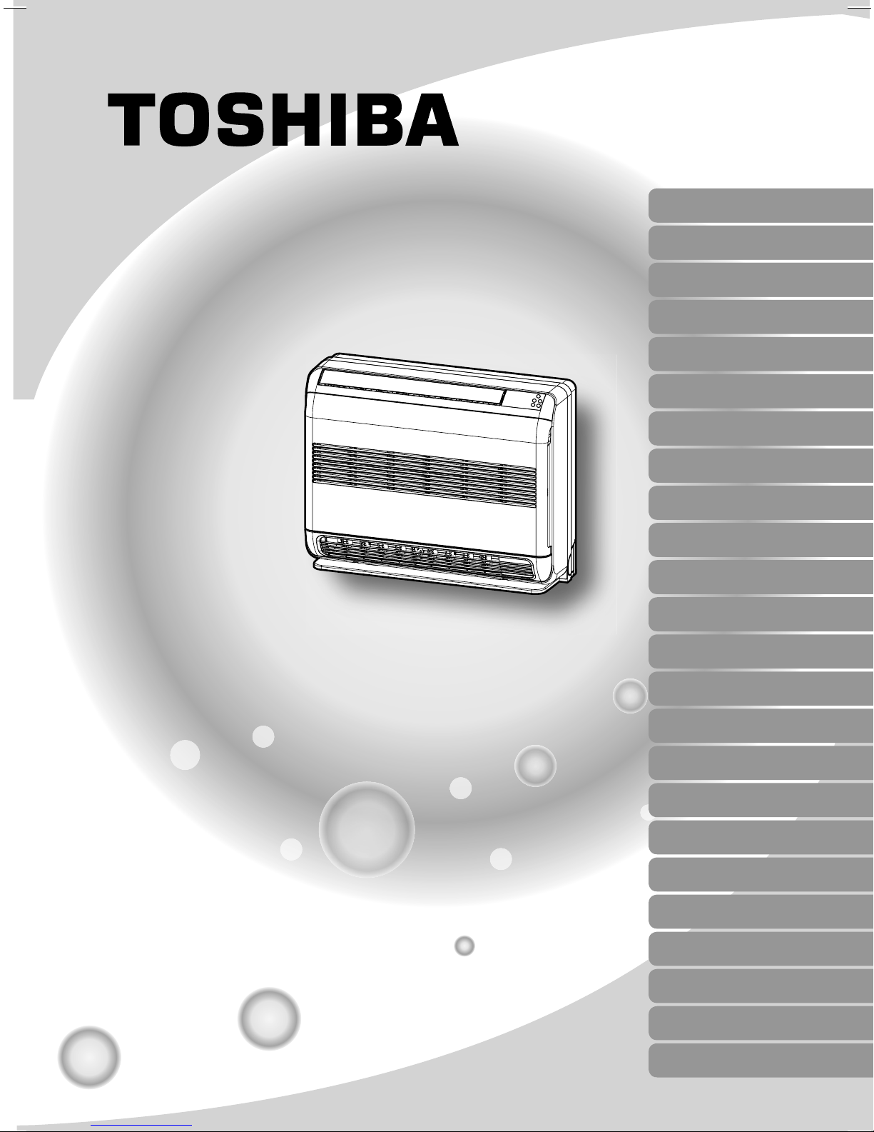
Toshiba RAS-10SAV, RAS-13SAV, RAS-18SAV,RAS-M14GAV-E, RAS-M18GAV-,RAS-3M18SAV-E,RAS-3M26GAV-E1, RAS-4M23SAV-E,RAS-4M27GAV-E1,RAS-5M34UAV-E Installation Manual
INSTALLATION MANUAL
AIR CONDITIONER (SPLIT TYPE)
ENGLISH
ESPAÑOL
FRANÇAIS
ITALIANO
DEUTSCH
PORTUGUÊS
POLSKI
ČESKY
PУCСКИЙ
HRVATSKI
MAGYAR
Indoor unit
RAS-(B) 10, 13, 18UFV Series
Outdoor unit
RAS-10, 13, 18SAV Series
RAS-M14GAV-E
RAS-M18GAV-E
RAS-3M18SAV-E
RAS-3M26GAV-E1
RAS-4M23SAV-E
RAS-4M27GAV-E1
RAS-5M34UAV-E
TÜRKÇE
NEDERLANDS
ΕΛΛΗΝΙΚΑ
SVENSKA
SUOMI
NORSK
DANSK
ROMÂNĂ
БЪЛГАРСКИ
EESTI
LATVISKI
SLOVENČINA
SLOVENŠČINA

CONTENTS
EN
PRECAUTIONS FOR SAFETY ....................................................1
INSTALLATION DIAGRAM OF INDOOR AND OUTDOOR
UNITS ...........................................................................................3
n Optional Installation Parts ....................................................... 3
INDOOR UNIT ..............................................................................4
n Installation Place ..................................................................... 4
n Cutting a Hole and Mounting Installation Plate ....................... 4
n How to Install Indoor Unit ........................................................5
n Concealed Installation .............................................................6
OUTDOOR UNIT ..........................................................................7
n Installation Place ..................................................................... 7
n Precautions about Installation in Regions with Snowfall and
Cold Temperatures ..................................................................7
n Draining off the Water from the Outdoor Unit ..........................7
n Refrigerant Piping Connection ................................................ 7
n Evacuating ..............................................................................8
n Wiring Connection ...................................................................8
n Electrical Work ........................................................................8
OTHERS ....................................................................................... 9
n Gas Leak Test .........................................................................9
n Setting of Remote Control Selector Switch .............................9
n Remote Control A-B Selection ................................................ 9
n Test Operation ........................................................................9
n Auto Restart Setting ...............................................................9
CONTENIDOS
ES
PRECAUCIONES SOBRE SEGURIDAD ....................................1
DIAGRAMA DE INSTALACIÓN DE LA UNIDAD
INTERIOR Y EXTERIOR .............................................................. 3
n Piezas de Instalación Opcional ..............................................3
UNIDAD INTERIOR .....................................................................4
n Lugar de Instalación ................................................................4
n Corte de un Orifi cio y Montaje de la Placa de Instalación ......4
n Cómo Instalar la Unidad Interior .............................................. 5
n Instalación Empotrada .............................................................6
UNIDAD EXTERIOR ....................................................................7
n Lugar de Instalación ................................................................7
n Precauciones sobre Instalación en Regiones con Nieve y
Temperaturas Frías .................................................................7
n Drenaje del Agua de la Unidad Exterior ..................................7
n Conexión de la Tubería Refrigerante ......................................7
n Evacuación .............................................................................8
n Conexión de Cables ................................................................8
n Trabajo Eléctrico ....................................................................8
OTROS .........................................................................................9
n Comprobación de Fugas .........................................................9
n Confi guración del Interruptor de Selección del Mando
a Distancia ...............................................................................9
n Mando a Distancia A-B Selección ...........................................9
n Prueba de Operación .............................................................9
n Ajuste de Reinicio Automático ................................................ 9
SOMMAIRE
FR
MESURES DE SÉCURITÉ ........................................................... 1
PLAN D’INSTALLATION DES UNITÉS INTÉRIEURE ET
EXTÉRIEURE ............................................................................... 3
n Pièces d’Installation en Option ...............................................3
UNITÉ INTÉRIEURE .................................................................... 4
n Endroit d’Installation ................................................................4
n Ouverture du Trou et Montage de la Plaque d’Installation .....4
n Installation de l’unité intérieure ................................................5
n Installation Dissimulée .............................................................6
UNITÉ EXTÉRIEURE ...................................................................7
n Endroit d’Installation ................................................................7
n Précautions à Prendre pour l’Installation dans les Régions
Sujettes aux Chutes de Neige et aux Températures
Froides ....................................................................................7
n Drainage de l’eau Dans l’unité Extérieure ...............................7
n Connexion du Tuyau Réfrigérant ............................................ 7
n Evacuation ..............................................................................8
n Connexion des Câbles ............................................................8
n Travaux Electriques ................................................................8
AUTRES .......................................................................................9
n Test de Fuite Gaz ....................................................................9
n Réglage du Sélecteur de Télécommande ...............................9
n Sélection de Télécommande A-B ............................................9
n Opération du Test ................................................................... 9
n Réglage de la Remise en Marche Automatique .....................9
INDICE
IT
PRECAUZIONI PER LA SICUREZZA ......................................... 1
SCHEMA DI INSTALLAZIONE DELL’ UNITÀ INTERNA
E DELL’ UNITÀ ESTERNA .......................................................... 3
n Componenti di Installazione Opzionali ...................................3
UNITÀ INTERNA ......................................................................... 4
n Luogo per l’Installazione .......................................................... 4
n Apertura di un Foro e Installazione della Lastra di
Installazione ............................................................................4
n Come Installare l’unità Interna ................................................. 5
n Installazione Incassata ............................................................6
UNITÀ ESTERNA ........................................................................7
n Luogo per l’Installazione .......................................................... 7
n Precauzioni sull’Installazione nelle Regioni Soggette a
Nevicate e Basse Temperature ...............................................7
n Scarico di Acqua dall’unità Esterna .........................................7
n Collegamento dei Tubi del Refrigerante ..................................7
n Evacuazione ...........................................................................8
n Collegamento dei Cavi ............................................................8
n Lavori Elettrici ..........................................................................8
ALTRI ...........................................................................................9
n Test per Perdite di Gas ........................................................... 9
n Impostazione del Selettore del Telecomando .........................9
n Selezione A-B del Telecomando .............................................9
n Funzionamento di Prova ......................................................... 9
n Impostazione per la Rimessa in Funzione Automatica ........... 9
PL
SPIS TREŚCI
ZASADY BEZPIECZEŃSTWA ....................................................1
SCHEMAT INSTALACYJNY URZĄDZENIA
WEWNĘTRZNEGO I ZEWNĘTRZNEGO ....................................3
n Dodatkowe Części Instalacyjne ............................................... 3
URZĄDZENIE WEWNĘTRZNE ...................................................4
n Miejsce Instalacji ..................................................................... 4
n Wycinanie Otworu oraz Montaż Płyty Instalacyjnej .................4
n Instalacja jednostki wewnętrznej .............................................5
n
Instalacja ukryta .........................................................................6
URZĄDZENIE ZEWNĘTRZNE ....................................................7
n Miejsce Instalacji ..................................................................... 7
n Zalecenia Dotyczące Instalacji Urządzenia w Rejonach z
Występowaniem Obfi tych Opadów Śniegu i Niskich
Temperatur ..............................................................................7
n Odprowadzanie wody z Jednostki Zewnętrznej ......................7
n Łączenie Instalacji Rurowej Czynnika Chłodniczego ..............7
n Usuwanie Powietrza ................................................................8
n Podłączenie Okablowania .......................................................8
n Prace Elektryczne ...................................................................8
INNE .............................................................................................9
n Próba Gazoszczelności ...........................................................9
n Ustawianie Przełącznika Wyboru Pilota ..................................9
n Ustawienia Przełącznika A-B Wyboru Pilota ...........................9
n Próba Działania .......................................................................9
n Włączanie Funkcji Automatycznego Wznawiania Pracy
(Auto Restart) .......................................................................... 9
CR
SADRŽAJ
MJERE SIGURNOSTI ..................................................................1
SHEMA UGRADNJE UNUTARNJIH I VANJSKIH JEDINICA .... 3
n Dodatni Dijelovi za Ugradnju Prema Izboru ............................ 3
UNUTARNJA JEDINICA .............................................................4
n Mjesto Ugradnje ...................................................................... 4
n Izrezivanje Rupe i Postavljanje Ploče za Ugradnju .................4
n Kako Ugraditi Unutarnju Jedinicu ............................................5
n
Skrivena Montaža.......................................................................6
VANJSKA JEDINICA ................................................................... 7
n Mjesto Ugradnje ...................................................................... 7
n Mjere Opreza za Montažu u Područjima s Jakim Snijegom i
Niskim Temperaturama ........................................................... 7
n Ispuštanje Vode iz Vanjske Jedinice .......................................7
n Sklop Cijevi Rashladnog Sredstva ..........................................7
n Pražnjenje ...............................................................................8
n Žičana Veza ............................................................................8
n Električni Radovi ......................................................................8
OSTALO ....................................................................................... 9
n Proba Isticanja Plina ................................................................ 9
n Položaji Prekidača za Odabir Daljinskog Upravljača ...............9
n Odabir A-B Pomoću Daljinskog Upravljača .............................9
n Probni Rad ..............................................................................9
n Postava za Automatsko Ponovno Pokretanje .........................9
INHALT
DE
SICHERHEITSVORKEHRUNGEN ..............................................1
EINBAUZEICHNUNGEN FÜR INNEN- UND
AUSSENGERÄT ..........................................................................3
n Zusätzlich erhältliche Installationsteile ...................................3
INNENGERÄT ..............................................................................4
n Aufstellungsort .........................................................................4
n Mauerdurchbruch und Befestigung der Montageplatte ..........4
n Installieren des Innengeräts ....................................................5
n Verborgene Montage ...............................................................6
AUSSENGERÄT ..........................................................................7
n Aufstellungsort .........................................................................7
n Vorsichtsmaßnahmen beim Einbau in Regionen mit
Schneefall und kalten Temperaturen ......................................7
n Ablassen des Wassers aus dem Außengerät .........................7
n Anschluß der Kühlmittelleitungen ............................................7
n Entleeren ................................................................................8
n Kabelanschlüsse ..................................................................... 8
n Elektrische Anschlüsse ..........................................................8
SONSTIGES ................................................................................. 9
n Überprüfung auf Gas-Undichtigkeit .........................................9
n Einstellen des Fernbedienungs-Wahlschalters .......................9
n Fernbedienung A-B Wahl ........................................................9
n Probelauf .................................................................................9
n Automatische Wiedereinschaltung ..........................................9
CZ
OBSAH
BEZPEČNOSTNÍ OPATŘENÍ ......................................................1
SCHÉMA INSTALACE VNITŘNÍ A VENKOVNÍ JEDNOTKY ..... 3
n Volitelné Doplňky pro Instalaci ................................................3
VNITŘNÍ JEDNOTKA ..................................................................4
n Místo Instalace ........................................................................ 4
n Vyvrtání Otvoru a Montáž Instalační Desky ............................4
n Montáž Vnitřní Jednotky ..........................................................5
n
Montáž Zapuštěné Jednotky ......................................................6
VENKOVNÍ JEDNOTKA .............................................................. 7
n Místo Instalace ........................................................................ 7
n Pokyny pro Instalaci v Oblastech, kde Padá Sníh a Jsou
Nízké Teploty ..........................................................................7
n Vypouštění Vody z Venkovní Jednotky ...................................7
n Spojování Chladivového Potrubí .............................................7
n Vyčerpávání Vzduchu .............................................................8
n Zapojení Vodičů ......................................................................8
n Elektrické Práce ......................................................................8
OSTATNĺ ......................................................................................9
n Zkouška Úniku Plynu ............................................................... 9
n Nastavení Přepínače Dálkového Ovládání ............................. 9
n Volba A-B na Dálkovém Ovládání ...........................................9
n Zkušební Provoz .....................................................................9
n Nastavení Automatického Znovuspuštění ...............................9
HU
TARTALOMJEGYZÉK
BIZTONSÁGI ELŐÍRÁSOK ......................................................... 1
BELTÉRI ÉS KÜLTÉRI EGYSÉGEK ÜZEMBE HELYEZÉSE .... 3
n Külön Rendelhető Alkatrészek ................................................3
BELTÉRI EGYSÉG ...................................................................... 4
n A Felszerelés Helye ................................................................ 4
n Lyuk Kivágása és a Felszerelése ............................................4
n A Beltéri Egység Felszerelése ................................................ 5
n
Rejtett Felszerelés......................................................................6
KÜLTÉRI EGYSÉG ......................................................................7
n A Felszerelés Helye ................................................................ 7
n Az Olyan Helyeken Történő Felszerelésre Vonatkozó
Óvintézkedések, Ahol Havazásra és Hidegre Lehet
Számítani ................................................................................7
n A Víz Elvezetése a Kültéri Egységből .....................................7
n Hűtőközegcső-Csatlakozások .................................................7
n Légtelenítés ............................................................................8
n Kábelezés ................................................................................8
n Elektromos Munka ...................................................................8
EGYEBEK ....................................................................................9
n Tömítettségvizsgálat ...............................................................9
n A Távirányító Kiválasztó Kapcsolójának Beállítása ................. 9
n A Távirányítón az A-B Állás Kiválasztása................................ 9
n Tesztüzem ...............................................................................9
n Automatikus Újraindítás Beállítás ............................................ 9
ÍNDICE
PT
PRECAUÇÕES RELATIVAS A SEGURANÇA ...........................1
ESQUEMA DE INSTALAÇÃO DAS UNIDADES INTERIOR
E EXTERIOR ................................................................................3
n Peças de Instalação Opcionais ...............................................3
UNIDADE INTERIOR ................................................................... 4
n Local de Instalação ................................................................. 4
n Cortar um Orifício e Montar a Placa de Instalação.................. 4
n Como Instalar a Unidade Interior ............................................ 5
n Instalação Oculta .....................................................................6
UNIDADE EXTERIOR ..................................................................7
n Local de Instalação ................................................................. 7
n Precauções na Instalação em Regiões com Queda de
Neve e Temperaturas Negativas .............................................7
n Drenar a Água da Unidade Exterior ........................................7
n Ligação das Condutas de Refrigeração ..................................7
n Purga de Ar .............................................................................8
n Ligações Eléctricas .................................................................8
n Trabalhos de Electricidade ......................................................8
OUTROS ......................................................................................9
n Teste de Fugas de Gás ...........................................................9
n Defi nição do Interruptor do Telecomando ...............................9
n Selecção A-B do Telecomando ...............................................9
n Execução do Teste .................................................................. 9
n Defi nindo de Reiniciação Automática ...................................... 9
RU
СОДЕРЖАНИЕ
MEPЫ БEЗOПACHOCTИ ...........................................................1
СХЕМА УСТАНОВКИ ВНУТРЕННЕГО И НАРУЖНОГО
БЛОКОВ......................................................................................3
n Oпционaльныe Уcтaновочныe Чacти ...................................3
BHУTPEHHИЙ БЛOК ................................................................. 4
n Mecто Уcтaновки ...................................................................4
n Пpоpeзaниe Отвepcтия и Монтaж Уcтaновочной
Плacтины ................................................................................4
n Установка внутреннего блока ............................................. 5
n Скрытая установка ...............................................................6
HAPУЖHЫЙ БЛOК ....................................................................7
n Mecто Уcтaновки ...................................................................7
n Меры предосторожности при установке в регионах с
вероятностью снегопада и низкими температурами .........7
n Слив воды из внешнего блока .............................................7
n Подcоeдинeниe Tpyбопpоводa для Xлaдaгeнтa ................ 7
n Удaлeниe Воздyxa .................................................................8
n Элeктpичecкиe Cоeдинeния ................................................8
n Элeктpомонтaжныe Рaботы .................................................8
ДPУГИE .......................................................................................9
n Пpовepкa Отcyтcтвия Утeчки Гaзa ..................................... 9
n Уcтaновкa положeния пepeключaтeля
диcтaнционного Упpaвлeния ................................................9
n Выбор А-В на пульте ДУ .......................................................9
n Пpобнaя Экcплyaтaция .........................................................9
n Уcтaновкa Aвтомaтичecкого Повтоpного Пycкa ................9
TR
İÇİNDEKİLER
GÜVENLİK ÖNLEMLERİ ............................................................1
İÇ VE DIŞ ÜNITENIN MONTAJ ŞEMASI ....................................3
n İsteğe Bağlı Montaj Parçaları ..................................................3
İÇ ÜNİTE ......................................................................................4
n Montaj Yeri .............................................................................. 4
n Bir Delik Açılması ve Montaj Plakasının Yerleştirilmesi........... 4
n Dış ünitenin monte edilmesi ....................................................5
n
Gizli yalıtım ................................................................................. 6
DIŞ ÜNİTE ....................................................................................7
n Montaj Yeri .............................................................................. 7
n Karlı ve Soğuk Bölgelerde Montaj İle İlgili Önlemler................ 7
n Dış üniteden suyun Tahliye Edilmesi ...................................... 7
n Soğutma Maddesi Boru Bağlantısı ..........................................7
n Boşaltma .................................................................................8
n Kablo Bağlantısı ...................................................................... 8
n Elektrik İşi ................................................................................8
DİĞERLERİ ..................................................................................9
n Gaz Kaçağı Testi .....................................................................9
n Uzaktan Kumanda Seçici Düğmesinin Ayarlanması ...............9
n Uzaktan Kumanda ile A-B Seçimi ........................................... 9
n Test İşlemi ...............................................................................9
n Otomatik Yeniden Başlama Ayarı ........................................... 9

INHOUDSOPGAVE
NL
VEILIGHEIDSVOORZORGEN .....................................................1
INSTALLATIESCHEMA VOOR BINNEN- EN
BUITENMODULES ......................................................................3
n Optionele Onderdelen ............................................................. 3
BINNENMODULE ........................................................................4
n Installatieplaats ........................................................................4
n Gat Boren en Montageplaat Bevestigen ................................. 4
n De binnenmodule installeren ...................................................5
n Verborgen installatie ................................................................6
BUITENMODULE ......................................................................... 7
n Installatieplaats ........................................................................7
n Voorzorgsmaatregelen voor Installatie in Gebieden met
Sneeuwval en Lage Temperaturen .........................................7
n Het water van de Buitenmodule Afvoeren ...............................7
n Koelleidingsaansluiting ............................................................7
n Afvoeren .................................................................................8
n Bedrading ................................................................................8
n Elektriciteit ...............................................................................8
OVERIGE .....................................................................................9
n Gaslektest ...............................................................................9
n De Keuzeschakelaar van de Afstandsbediening Instellen ...... 9
n Afstandsbediening Keuze A-B ................................................. 9
n Testwerking .............................................................................9
n Automatische Herstart Instellen .............................................. 9
ΠΕΡΙΕXOΜΕΝΑ
GR
ΠΡOΦΥΛΑΞΕΙΣ ΑΣΦΑΛΕΙΑΣ ......................................................1
ΔΙΆΓΡΑΜΜΑ ΕΓΚΑΤΆΣΤΑΣΗΣ ΤΗΣ ΕΣΩΤΕΡΙΚΉΣ ΚΑΙ
ΕΞΩΤΕΡΙΚΉΣ ΜOΝΆΔΑΣ ..........................................................3
n Προαιρετικά Eξαρτήµατα Eγκατάστασησ ...........................3
ΕΣΩΤΕΡΙΚΉ ΜOΝΆΔΑ ...............................................................4
n Σηµείο Eγκατάστασησ ..........................................................4
n
Κψιµο Τρύπασ και Τοποθέτηση Πλάτησ Εγκατάστασησ
n Πώσ να Eγκαταστήσετε την Eσωτερική µονάδα.................. 5
n Κρυφή Εγκατάσταση ............................................................... 6
ΕΞΩΤΕΡΙΚΉ ΜOΝΆΔΑ ...............................................................7
n Σηµείo Εγκατάστασησ ..........................................................7
n Προφυλάξεισ Σχετικά µε την Εγκατάσταση σε Περιέσ
µε Χιονπτωση και Χαµηλέσ Θερµοκρασίεσ ......................7
n Απoστράγγιση τoυ νερoύ απ την Eξωτερική µoνάδα ..... 7
n Σύνδεση Ψυκτικών Σωληνώσεων ........................................7
n Εκκένωση ...............................................................................8
n Σύνδεση Καλωδίωσησ ...........................................................8
n Ηλεκτρικέσ Εργασίεσ ............................................................8
ΛOΙΠΑ ..........................................................................................9
n Έλεγχoσ ∆ιαρρoήσ Αερίoυ ...................................................9
n Ρύθµιση τoυ ∆ιακπτη Eπιλoγήσ Τηλεχειριστηρίoυ .........9
n Επιλογή Α-Β τoυ Τηλεχειριστηρίoυ.....................................9
n ∆oκιµή Λειτoυργίασ .............................................................. 9
n Auto Restart Ρύθµιση ...........................................................9
...4
INNEHÅLL
SV
SÄKERHETSANVISNINGAR ......................................................1
INSTALLATIONSSCHEMA FÖR INOMHUS- OCH
UTOMHUSENHETEN ..................................................................3
n Valfria Installationskomponenter ............................................. 3
INOMHUSENHETEN ...................................................................4
n Plats för Montering ..................................................................4
n Skära ut ett Hål och Fästa Monteringsplåten ..........................4
n Så här monteras inomhusenheten ..........................................5
n Dold montering ........................................................................6
UTOMHUSENHETEN ..................................................................7
n Plats för Montering ..................................................................7
n Försiktighetsåtgärder vid Installation i Områden med Snöfall
och Kalla Temperaturer ...........................................................7
n Dränering av Vatten Från Utomhusenheten ............................ 7
n Anslutning av Köldmedierör .................................................... 7
n Vakuumsugning .......................................................................8
n Ledningsdragningar .................................................................8
n Elarbeten .................................................................................8
ÖVRIGT ........................................................................................9
n Kontrollera Gasläckor ..............................................................9
n Inställning av Fjärrkontrollens Omkopplare .............................9
n Fjärrkontroll A-B Val ................................................................9
n Testkörning ..............................................................................9
n Inställning av Omstart .............................................................. 9
SISÄLLYSLUETTELO
FI
VAROTOIMENPITEET ................................................................. 1
SISÄ- JA ULKOYKSIKKÖJEN ASENNUSKAAVIO ...................3
n Lisävarusteena Saatavat Asennusosat ...................................3
SISÄYKSIKKÖ .............................................................................4
n Asennuspaikka ........................................................................4
n Aukon Tekeminen ja Asennuslevyn Kiinnittäminen ................. 4
n Sisäyksikön asennus ...............................................................5
n Piilotettu asennus ....................................................................6
ULKOYKSIKKÖ ...........................................................................7
n Asennuspaikka ........................................................................7
n Huomiot Asennuksesta Alueille, Joissa on Lumisadetta ja
Kylmiä Lämpötiloja ..................................................................7
n Veden Poistaminen Ulkoyksiköstä ..........................................7
n Kylmänesteputkien Liittäminen ................................................7
n Tyhjentäminen .........................................................................8
n Johtoliitännät ........................................................................... 8
n Sähkötyöt ................................................................................8
MUUT ...........................................................................................9
n Kaasuvuototesti .......................................................................9
n Kauko-ohjaimen Valitsinkytkimen Säätäminen........................ 9
n Kauko-ohjaimen A-B Valinta ................................................... 9
n Koekäyttö ................................................................................9
n Automaattisen Uudelleenkäynnistyksen Asettaminen ............. 9
RO
CUPRINS
MĂSURI DE SIGURANŢĂ ........................................................... 1
SCHEMA DE INSTALARE A UNITĂŢILOR INTERIOARĂ
ŞI EXTERIOARĂ .......................................................................... 3
n Piese de Instalare Opţionale ...................................................3
UNITATE INTERIOARĂ ............................................................... 4
n Locul de Instalare ....................................................................4
n Executarea unei Găuri şi Montarea Plăcii de Instalare............ 4
n Cum se Instalează Unitatea Interioară ....................................5
n
Instalarea Mascată ..................................................................... 6
UNITATEA EXTERIOARĂ ...........................................................7
n Locul de Instalare ....................................................................7
n Măsuri de Precauţie privind Instalarea în Regiuni cu
ninsori Abundente şi Temperaturi Scăzute .............................7
n Drenarea Apei din Unitatea Exterioară .................................... 7
n Racordarea Ţevilor de lichid Refrigerent .................................7
n Evacuarea .............................................................................. 8
n Racordarea Cablurilor ............................................................. 8
n Lucrările Electrice ....................................................................8
ALTELE ........................................................................................ 9
n Verifi carea Scurgerilor de Gaz ................................................9
n Setarea Butonului Selector al Telecomenzii ............................ 9
n Alegerea Telecomenzii A-B .....................................................9
n Verifi carea Funcţionării ............................................................9
n Setarea Auto Restart (Repornirea Automată) .........................9
INNHOLD
NO
SIKKERHETSREGLER ...............................................................1
KOBLINGSSKJEMA FOR INNE- OG UTENDØRSENHETEN ...3
n Ekstrautstyr .............................................................................3
INNENHETEN ..............................................................................4
n Plassering ................................................................................4
n Lage et Hull og Montere Montasjeplaten ................................. 4
n Slik Monterer du Innendørsenheten ........................................5
n Skjult Montering .......................................................................6
UTENDØRSENHET .....................................................................7
n Montasjested ...........................................................................7
n Forholdsregler ved Installasjon i Områder med Snø og Lave
Temperaturer ...........................................................................7
n Drenere Vannet fra Utendørsenheten .....................................7
n Tilkobling av Kjølerørene ......................................................... 7
n Evakuering ..............................................................................8
n Tilkobling av Ledninger ........................................................... 8
n Elektrisk Arbeid .......................................................................8
ANNET .........................................................................................9
n Gasslekkasjetest ..................................................................... 9
n Stille Fjernkontrollbryteren .......................................................9
n Fjernkontroll A-B Valg ............................................................. 9
n Testdrift ...................................................................................9
n Innstillinger for Auto Restart ....................................................9
BG
СЪДЪРЖАНИЕ
ПРЕДПАЗНИ МЕРКИ ЗА БЕЗОПАСНОСТ ..............................1
ДИАГРАМА ЗА ИНСТАЛИРАНЕ НА ВЪТРЕШНИЯТ И
ВЪНШНИЯТ МОДУЛ..................................................................3
n Допълнителни Eлементи за Mонтаж ...................................3
ВЪТРЕШЕН МОДУЛ ..................................................................4
n Място за Mонтаж .................................................................. 4
n Пробиване На Отвор и Монтиране Намонтажната
Планка ....................................................................................4
n Как се Монтира Вътрешното Тяло ......................................5
n Скрит монтаж ........................................................................6
ВЪНШЕН МОДУЛ.......................................................................7
n Място за Mонтаж .................................................................. 7
n Предпазни Mерки при Mонтиране в Pегиони
със Cнеговалеж и Hиски Tемператури ...............................7
n Източване на Водата от Външното Тяло ............................ 7
n Свързване на Tръбите за Хладилния Агент....................... 7
n Създаване на Bакуум ..........................................................8
n Свързване на Kабелите ........................................................ 8
n Работа по Eлектрическата Cистема ...................................8
ИДРУГИ .......................................................................................9
n Тест за Hаличие на Газови Tечове ..................................... 9
n Настройване на Избиращия Превключвател за
Дистанционно Управление ................................................... 9
n Избиране на Hастройки „А” или „В” на
Дистанционното Управление ...............................................9
n Тестов Pежим ........................................................................9
n Настройка за Aвтоматично Pестартиране ........................ 9
INDHOLD
DK
SIKKERHEDSFORHOLDSREGLER ...........................................1
INSTALLATIONSDIAGRAM FOR INDDØRS OG UDENDØRS
ENHED .........................................................................................3
n Valgfrie Installationsdele .........................................................3
INDENDØRS ENHED ..................................................................4
n Installationssted .......................................................................4
n Skæring af et Hul og Montering af Installationspladen ............4
n Sådan Installeres den Indendørs Enhed .................................5
n Skjult Installation .....................................................................6
UDENDØRS ENHED ...................................................................7
n Installationssted .......................................................................7
n Forholdsregler ved Installation i regioner, Hvor der Falder
Sne og Hvor der er Lave Temperaturer ..................................7
n Dræning af vand fra den Udendørs enhed ..............................7
n Kølerørsforbindelsen ...............................................................7
n Evakuering ..............................................................................8
n Tilslutning af Kabel ..................................................................8
n Elektrisk Arbejde .....................................................................8
ANDET .........................................................................................9
n Gaslækagekontrol ................................................................... 9
n Indstilling af Fjernbetjeningskontakten ....................................9
n Valg af Fjernbetjening A-B ...................................................... 9
n Testdrift ..................................................................................9
n Auto-Omstartsindstilling ..........................................................9
SISUKORD
EE
OHUTUSABINÕUD ...................................................................... 1
SISE- JA VÄLISSEADMETE PAIGALDUSSKEEM .................... 3
n Valikulised Paigaldusdetailid ...................................................3
SISESEADE .................................................................................4
n Paigalduskoht ..........................................................................4
n Augu Tegemine ja Paigaldusplaadi Monteerimine ..................4
n Siseseadme Paigaldamine ......................................................5
n Peidetud Paigaldamine ...........................................................6
VÄLISSEADE ............................................................................... 7
n Paigalduskoht ..........................................................................7
n Ettevaatusabinõud Seadme Paigaldamiseks Madalate
Temperatuuridega ja Lumistes Piirkondades .......................... 7
n Vee Väljutamine Välisseadmest ..............................................7
n Jahutussegu Torustiku Ühendamine .......................................7
n Tühjendamine .........................................................................8
n Kaablite Ühendamine ..............................................................8
n Elektrilised Tööd ......................................................................8
MUU .............................................................................................9
n Gaasilekke Test .......................................................................9
n Kaugjuhtimispuldi Valija Seadistamine .................................... 9
n Kaugjuhtimispuldi A- ja B-Sätted .............................................9
n Testfunktsioon .........................................................................9
n Automaatse Taaskäivitamise Säte ..........................................9
LV
SATURS
PROFILAKTISKIE DROŠĪBAS PASĀKUMI ...............................1
IEKŠTELPAS UN ĀRA AGREGĀTA MONTĀŽAS SHĒMA ....... 3
n Papildaprīkojuma Montāžas Daļas ..........................................3
IEKŠTELPAS AGREGĀTS .......................................................... 4
n Montāžas Vieta ........................................................................4
n Cauruma Izveide un Montāžas Plāksnes Uzstādīšana ...........4
n Kā Uzstādīt Iekštelpu Ierīci ...................................................... 5
n
Uzstādīšana zem apmetuma......................................................6
ĀRA AGREGĀTS ........................................................................7
n Montāžas Vieta ........................................................................7
n Drošības Norādījumi Par Iekārtas Uzstādīšanu Reģionos,
Kuros Pastāv Snigšanas un Zemas Temperatūras Iespēja ....7
n Ūdens Novadīšana no Ārējās Ierīces ......................................7
n Aukstumaģenta Cauruļu Savienojumi .....................................7
n Izsūknēšana ............................................................................ 8
n Kabeļu Savienojumi .................................................................8
n Elektroinstalācijas Darbi ..........................................................8
PAPILDINFORMĀCIJA ...............................................................9
n Gāzes Noplūdes Pārbaude .....................................................9
n Tālvadības Pults Selektorpārslēga Iestatīšana .......................9
n Tālvadības Pults Režīma A/B Izvēle .......................................9
n Darbības Pārbaude ................................................................. 9
n Darbības Automātiskās Atsākšanas Funkcijas Iestatīšana .....9
SK
OBSAH
BEZPEČNOSTNÉ ZÁSADY ........................................................1
INŠTALAČNÁ SCHÉMA VNÚTORNEJ A VONKAJŠEJ JEDNOTKY
n Voliteľné Inštalačné Diely ........................................................3
VNÚTORNÁ JEDNOTKA ............................................................4
n Miesto Inštalácie ......................................................................4
n Zhotovenie Diery a Montáž Inštalačnej Lišty ...........................4
n Inštalácia Vnútornej Jednotky ................................................. 5
n
Skrytá Montáž ............................................................................6
VONKAJŠIA JEDNOTKA ............................................................7
n Miesto Inštalácie ......................................................................7
n Upozornenie pre Inštaláciu v Oblastiach so Snežením a
Nízkymi Teplotami ...................................................................7
n Odvádzanie Vody z Vonkajšej Jednotky .................................7
n Spájanie Chladiacich Rúrok ....................................................7
n Vyčerpanie Vzduchu ...............................................................8
n Pripojenie Vodičov ...................................................................8
n Elektroinštalačná Práca ...........................................................8
INÉ ................................................................................................ 9
n Test Unikania Plynu ................................................................ 9
n Nastavenie Prepínača na Diaľkovom Ovládači .......................9
n Voľba A-B na Diaľkovom Ovládači ..........................................9
n Testovacia Prevádzka .............................................................9
n Nastavenie Automatického Reštartu .......................................9
....3
VSEBINA
SI
VARNOSTNI UKREPI ..................................................................1
NAMESTITVENA SHEMA NOTRANJE IN ZUNANJE ENOTE
n Izbirni Namestitveni Deli ..........................................................3
NOTRANJA ENOTA .................................................................... 4
n Mesto za Namestitev ...............................................................4
n Rezanje Luknje in Montaža Namestitvene Plošče ..................4
n Kako Namestiti Notranjo Enoto ...............................................5
n Vgradna Namestitev ................................................................6
ZUNANJA ENOTA .......................................................................7
n Mesto za Namestitev ...............................................................7
n Opozorila pri Namestitvi na Območjih s Snežnimi
Padavinami in Nizkimi Temperaturami .................................... 7
n Odvajanje Vode iz Zunanje Enote ...........................................7
n Priključitev Hladilnih Cevi ........................................................7
n Izčrpavanje .............................................................................8
n Priključitev Napeljave .............................................................. 8
n Električarsko Delo ...................................................................8
DRUGO ........................................................................................9
n Preizkus Uhajanja Plina .......................................................... 9
n Nastavitev Izbirnega Stikala Daljinskega Upravljalnika ...........9
n Izbira Nastavitve A-B na Daljinskem Upravljalniku ..................9
n Preizkus Delovanja ..................................................................9
n Nastavitev za Samodejni Ponovni Zagon ................................ 9
....3
PRECAUTIONS FOR SAFETYPRECAUTIONS FOR SAFETY
Be sure to read this installation manual carefully before installing.
Recommend to the owner to perform maintenance periodically when using over long periods of time.
Be sure to follow the precautions provided here to avoid safety risks. The symbols and their meanings are shown below.
DANGER : It indicates that incorrect use of this unit can result in a high possibility of severe injury (*1) or death.
WARNING : It indicates that incorrect use of this unit may cause severe injury or death.
CAUTION : It indicates that incorrect use of this unit may cause personal injury (*2), or property damage (*3).
*1 : A severe injury refers to blindness, injury, burns (hot or cold), electrical shock, bone fracture, or poisoning that leaves aftereffects and
requires hospitalization or extended out-patient treatment.
*2 : Personal injury means a slight accident, burn, or electrical shock which does not require admission or repeated hospital treatment.
*3 : Property damage means greater damage which affects assets or resources.
For general public use
Power supply cord of parts of appliance for outdoor use shall be at least polychloroprene sheathed fl exible cord (design H07RN-F) or cord designation
60245 IEC66 (1.5 mm
2
or more) (Shall be installed in accordance with national wiring regulations).
CAUTION
• THIS AIR CONDITIONER USES THE NEW HFC REFRIGERANT (R410A), WHICH DOES NOT DESTROY THE OZONE LAYER.
R410A refrigerant is apt to be affected by impurities such as water, oxidizing membranes, and oils because the pressure of R410A refrigerant is approx.
1.6 times of refrigerant R22. As well as the adoption of this new refrigerant, refrigerating machine oil has also been changed. Therefore, during installation
work, be sure that water, dust, former refrigerant, or refrigerating machine oil does not enter the refrigeration cycle of a new-refrigerant air conditioner.
To avoid mixing refrigerant and refrigerating machine oil, the sizes of charging port connecting sections on the main unit are different from those for the
conventional refrigerant, and different size tools are also required. For connecting pipes, use new and clean piping materials with highpressure withstand
capabilities, designed for R410A only, and ensure that water or dust does not enter. Moreover, do not use any existing piping as its pressure withstand
may be insuffi cient and may contain impurities.
New refrigerant air conditioner installation
DANGER
• FOR USE BY QUALIFIED PERSONS ONLY.
• MEANS FOR DISCONNECTION FROM THE SUPPLY HAVING A CONTACT SEPERATION OF AT LEAST 3 mm IN ALL POLES MUST BE
INCORPORATED IN THE FIXED WIRING.
• TURN OFF MAIN POWER SUPPLY BEFORE ATTEMPTING ANY ELECTRICAL WORK. MAKE SURE ALL POWER SWITCHES ARE OFF.
FAILURE TO DO SO MAY CAUSE ELECTRIC SHOCK.
• CONNECT THE CONNECTING CABLE CORRECTLY. IF THE CONNECTING CABLE IS CONNECTED WRONGLY, ELECTRIC PARTS MAY BE
DAMAGED.
• CHECK THE EARTH WIRE THAT IT IS NOT BROKEN OR DISCONNECTED BEFORE INSTALLATION.
• DO NOT INSTALL NEAR CONCENTRATIONS OF COMBUSTIBLE GAS OR GAS VAPORS. FAILURE TO FOLLOW THIS INSTRUCTION CAN
RESULT IN FIRE OR EXPLOSION.
• TO PREVENT OVERHEATING THE INDOOR UNIT AND CAUSING A FIRE HAZARD, PLACE THE UNIT WELL AWAY (MORE THAN 2 M) FROM
HEAT SOURCES SUCH AS RADIATORS, HEATERS, FURNACE, STOVES, ETC.
• WHEN MOVING THE AIR CONDITIONER FOR INSTALLING IT IN ANOTHER PLACE AGAIN, BE VERY CAREFUL NOT TO GET THE SPECIFIED
REFRIGERANT (R410A) WITH ANY OTHER GASEOUS BODY INTO THE REFRIGERATION CYCLE. IF AIR OR ANY OTHER GAS IS MIXED IN
THE REFRIGERANT, THE GAS PRESSURE IN THE REFRIGERATION CYCLE BECOMES ABNORMALLY HIGH AND IT RESULTINGLY CAUSES
BURST OF THE PIPE AND INJURIES ON PERSONS.
• IN THE EVENT THAT THE REFRIGERANT GAS LEAKS OUT OF THE PIPE DURING THE INSTALLATION WORK, IMMEDIATELY LET FRESH AIR
INTO THE ROOM. IF THE REFRIGERANT GAS IS HEATED BY FIRE OR SOMETHING ELSE, IT CAUSES GENERATION OF POISONOUS GAS.
• WHEN INTALLING OR RE-INSTALLING THE AIR CONDITIONER, DO NOT INJECT AIR OR OTHER SUBSTANCES BESIDES THE DESIGNATED
REFRIGERANT “R410A” INTO THE REFRIGERATING CYCLE. IF AIR OR OTHER SUBSTANCES ARE MIXED, AN ABNORMAL PRESSURE CAN
OCCUR IN THE REFRIGERATING CYCLE, AND THIS CAN CAUSE AN INJURY DUE TO A PIPE RUPTURE.
1

WARNING
• Installation work must be requested from the supplying retail dealership or professional vendors. Self-installation may cause water leakage, electrical
shock, or fi re as a result of improper installation.
• Specifi ed tools and pipe parts for model R410A are required, and installation work must be done in accordance with the manual. HFC type refrigerant
R410A has 1.6 times more pressure than that of conventional refrigerant (R22). Use the specifi ed pipe parts, and ensure correct installation, otherwise
damage and/or injury may be caused. At the same time, water leakage, electrical shock, and fi re may occur.
• Be sure to install the unit in a place which can suffi ciently bear its weight. If the load bearing of the unit is not enough, or installation of the unit is
improper, the unit may fall and result in injury.
• Electrical work must be performed by a qualifi ed electrical engineer in accordance with the code governing such installation work, internal wiring
regulations, and the manual. A dedicated circuit and the rated voltage must be used. Insuffi cient power supply or improper installation may cause
electrical shock or fi re.
• Use a cabtyre cable to connect wires in the indoor/outdoor units. Midway connection, stranded wire, and single-wire connections are not allowed.
Improper connection or fi xing may cause a fi re.
• Wiring between the indoor unit and outdoor units must be well shaped so that the cover can be fi rmly placed. Improper cover installation may cause
increased heat, fi re, or electrical shock at the terminal area.
• Be sure to use only approved accessories or the specifi ed parts. Failure to do so may cause the unit to fall, water leakage, fi re or electrical shock.
• After the installation work, ensure that there is no leakage of refrigerant gas. If the refrigerant gas leaks out of the pipe into the room and is heated by
fi re or something else from a fanheater, stove or gas range, it causes generation of poisonous gas.
• Make sure the equipment is properly earthed. Do not connect the earth wire to a gas pipe, water pipe, lightning conductor, or telephone earth wire.
Improper earth work may be the cause of electrical shock.
• Do not install the unit where fl ammable gas may leak. If there is any gas leakage or accumulation around the unit, it can cause a fi re.
• Do not select a location for installation where there may be excessive water or humidity, such as a bathroom. Deterioration of insulation may cause
electrical shock or fi re.
• Installation work must be performed following the instructions in this installation manual. Improper installation may cause water leakage, electrical shock
or fi re. Check the following items before operating the unit.
- Be sure that the pipe connection is well placed and there are no leaks.
- Check that the service valve is open. If the service valve is closed, it may cause overpressure and result in compressor damage. At the same time, if
there is a leak in the connection part, it may cause air suction and overpressure, resulting burst or injury.
• In pump down operations, ensure to perform the following procedures.
- Do not inject air into the refrigeration cycle.
- Be sure to close both service valves and stop the compressor before removing the refrigerant pipe. If removing the refrigerant pipe while the
compressor is operating with the service valves opened, it may cause to air absorbed and abnormal high pressure inside the refrigeration cycle and
resulting burst or injury.
• Do not modify the power cable, connect the cable midway, or use a multiple outlet extension cable. Doing so may cause contact failure, insulation
failure, or excess current, resulting in fi re or electrical shock.
• If you detect any damage, do not install the unit. Contact your supplying dealer immediately.
• Never modify this unit by removing any of the safety guards or bypassing any of the safety interlock switches.
EN
ES
FR
IT
DE
PT
PL
CZ
RU
CAUTION
• Please read this installation manual carefully before installing the unit. It contains further important instructions for proper installation.
• Exposure of unit to water or other moisture before installation could result in electric shock. Do not store it in a wet basement or expose to rain or water.
• After unpacking the unit, examine it carefully for possible damage.
• Do not install in a place that can increase the vibration of the unit. Do not install in a place that can amplify the noise level of the unit or where noise and
discharged air might disturb neighbors.
• This appliance must be connected to the main power supply by means of a circuit breaker depending on the place where the unit is installed. Failure to
do so may cause electrical shock.
• Follow the instructions in this installation manual to arrange the drain pipe for proper drainage from the unit. Ensure that drained water is discharged.
Improper drainage can result in water leakage, causing water damage to furniture.
• Tighten the fl are nut with a torque wrench using the prescribed method. Do not apply excess torque. Otherwise, the nut may crack after a long period of
usage and it may cause the leakage of refrigerant.
• Wear gloves (heavy gloves such as cotton gloves) for installation work. Failure to do so may cause personal injury when handling parts with sharp
edges.
• Do not touch the air intake section or the aluminum fi ns of the outdoor unit. It may cause injury.
• Do not install the outdoor unit in a place which can be a nest for small animals. Small animals could enter and contact internal electrical parts, causing a
failure or fi re.
• Request the user to keep the place around the unit tidy and clean.
• Make sure to conduct a trial operation after the installation work, and explain how to use and maintain the unit to the customer in accordance with the
manual. Ask the customer to keep the operation manual along with the installation manual.
REQUIREMENT OF REPORT TO THE LOCAL POWER SUPPLIER
Please make absolutely sure that the installation of this appliance is reported to the local power supplier before installation. If you experience any problems
or if the installation is not accepted by the supplier, the service agency will take adequate countermeasures.
CR
HU
TR
NL
GR
SV
FI
NO
DK
RO
BG
EE
LV
SK
SI
2

INSTALLATION DIAGRAM OF INDOOR AND OUTDOOR UNITSINSTALLATION DIAGRAM OF INDOOR AND OUTDOOR UNITS
Do not allow the drain hose to get
Air fi lter
1 Installation plate
slack.
50 mm or more
6 Filter
5 Filter
3 Batteries
2 Wireless remote control
7 Mounting screw 9 Insulation sheet
8 Pan head
wood screw
100 mm or more
4 Remote control holder
600 mm or more only
when unobstructed
to the front and both
sides.
70 mm or more
Vinyl tape
Apply after carrying
out a drainage test.
(D)
100 mm or more
50 mm or more
Shield pipe
Saddle
Cut the piping
hole sloped
slightly.
Make sure to run the drain hose
sloped downward.
The auxiliary piping can be
connected to the left, rear left, rear
right, right, bottom right or bottom
left.
Right
Rear right
Bottom right
Rear left
Left
Bottom left
Insulate the refrigerant pipes
separately with insulation, not
together.
8 mm thick heat resisting
polyethylene foam
Optional Installation Parts
Part
code
Refrigerant piping
Liquid side : ∅6.35 mm
Gas side : ∅9.52 mm
A
(RAS-(B) 10, 13UFV Series)
: ∅12.7 mm
(RAS-(B) 18UFV Series)
Pipe insulating material
B
(polyethylene foam, 8 mm thick)
Putty, PVC tapes
C
Parts name Q’ty
(C)
600 mm or more
One
each
1
One
each
(B)
Extension
drain hose
(Not available,
provided by installer)
600 mm or more
In case of right or left piping
Cut dot-line area
(A)
Fixing bolt arrangement of outdoor unit
RAS-10, 13, 18SAV Series
• Secure the outdoor unit with fi xing bolts and nuts if the unit is likely to be exposed
to a strong wind.
• Use ∅8 mm or ∅10 mm anchor bolts and nuts.
• If it is necessary to drain the defrost water, attach drain nipple and cap water proof
to the bottom plate of the outdoor unit before installing it.
108 mm
28 mm
86 mm
320 mm
Air outlet
600 mm
X When using a multi-system outdoor unit is used, refer to the installation manual
provided with the model concerned.
25 mm
125 mm
Air inlet
Drain outlet
102 mm
* Drain nipple and cap
water proof are packed
in outdoor unit.
90 mm
3

INDOOR UNITINDOOR UNIT
Installation Place
• A place which provides the spaces around the indoor unit as shown in the
diagram.
• A place where there are no obstacles near the air inlet and outlet.
• A place which allows easy installation of the piping to the outdoor unit.
• A place which allows the front panel to be opened.
CAUTION
• Direct sunlight to the indoor unit’s wireless receiver should be avoided.
• The microprocessor in the indoor unit should not be too close to RF
noise sources.
(For details, see the owner’s manual)
Remote control
• A place where there are no obstacles such as a curtain that may block the
signal from the remote control.
• Do not install the remote control in a place exposed to direct sunlight or
close to a heating source such as a stove.
• Keep the remote control at least 1 m apart from the nearest TV set or
stereo equipment (This is necessary to prevent image disturbances or
noise interference).
• The location of the remote control should be determined as shown below.
(Side view) (Top view)
60
Indoor unit
90
7 m
Reception range
* : Axial distance
Remote
control
7 m
Reception range
7 m
45
45
Remote control
Cutting a Hole and Mounting
Installation Plate
Mounting the installation plate and screw position
(205)
(600)
15
(700)
150
230
670
15
15
90
15
272
Floor
560
(Unit : mm)
590
Wall
When the installation plate is directly mounted
on the wall
1. Securely fi t the installation plate onto the wall by screwing it in the upper
and lower parts to hook up the indoor unit.
2. To mount the installation plate on a concrete wall with anchor bolts, use
the anchor bolt holes as illustrated in the below fi gure.
3. Install the installation plate horizontally in the wall.
Installation plate
(Keep horizontal direction)
Anchor bolt
Projection
∅5 mm hole
Clip anchor
(local parts)
7 Mounting screw
∅4 mm x 25 s
15 mm or less
EN
ES
FR
IT
DE
PT
PL
CZ
RU
CR
HU
TR
NL
Cutting a hole
(Side piping)(Rear piping)
60100
45
(Bottom piping)
60
100 70
1. After determining the pipe hole position, drill the pipe hole (∅65 mm) at a
slight downward slant to the outdoor side.
45
100
45
45
: Pipe hole (∅65 mm)
NOTE
• When drilling a wall that contains a metal lath, wire lath or metal plate, be
sure to use a pipe hole brim ring sold separately.
CAUTION
Failure to fi rmly install the unit may result in personal injury and property
damage if the unit falls.
• In case of block, brick, concrete or similar type walls, make ∅5 mm holes
in the wall.
• Insert clip anchors for appropriate mounting screws 7.
4
GR
SV
FI
NO
DK
RO
BG
EE
LV
SK
SI

How to Install Indoor Unit
2. Put water in the drain pan and make sure that the water is drained out of
doors.
3. When connecting extension drain hose, insulate the connecting part of
1. Remove the air inlet grille. Open the air inlet grille and remove the strap.
extension drain hose with shield pipe.
2. Remove the front panel (Remove the 4 screws).
Front panel
Hook
Drain hose
CAUTION
Arrange the drain pipe for proper drainage from the unit.
Improper drainage can result in dew-dropping.
Air inlet grille
Wiring connection
Wiring of the connection cable is necessary to remove the front panel.
1. Remove the terminal cover and cord clamp.
2. Insert the connecting cable (according to the local rule) into the pipe hole
Layout of connection piping
100
66
85
49
108
542 58
29
64
40
120
R45
4085
112
148
on the wall.
3. Take out the connecting cable through the cable slot on the rear panel so
that it protrudes about 50 cm from the front.
4. Insert the connecting cable fully into the terminal block and secure it
tightly with screws.
5. Tightening torque : 1.2 N·m (0.12 kgf·m)
6. Secure the connecting cable with the cord clamp.
7. Fix the terminal cover, install the front panel and grille inlet.
CAUTION
• Be sure to refer to the wiring system diagram labeled inside the front
panel.
• Check local electrical cords and also any specifi c wiring instructions or
limitations.
Shield pipe
Extension drain hose
Inside the room
Connection piping
210
163
47
49
Treatment of piping connection
1) Check the fl are nut connections for the gas leak with a gas leak detector
or soap water.
2) To prevent gap in slit, fasten top and bottom with tape.
3) Slit is covered with tape.
4) Fasten with supplied Insulate sheet to prevent gap on the top of slit.
Gas leak check
Tape
Slit
Tape
9 Insulation sheet
Drainage
1. Run the drain hose sloped downwards.
NOTE
• The hole should be made at a slight downward slant on the outdoor side.
Do not form the
Do not rise the
drain hose.
drain hose into
a wavy shape.
Hook
Terminal cover
Screw
Screw
Cord clamp
Earth screw
20 mm
430 mm
Stripping length of the connecting cable
NOTE
• Use stranded wire only.
• Wire type : H07RN-F or 60245 IEC66 (1.0 mm
110 mm
10 mm
50 mm
2
or more)
Terminal
block
Earth line
Earth line
Do not put the
drain hose end
into water.
Do not put the
drain hose end in
the drainage ditch.
5

2
Mounting directly on the fl oor.
1) Fix the leg of indoor unit on the fl oor with 2 mounting screws.
2) Fix the upper part of indoor unit on the wall with 4 mounting screws.
(Floor installation)
Slit
6 screw
(M4 x 25L)
NOTE
• In case the plinth is fi xed to the wall, please make sure to cut out the slit
on the left and right side of the main part.
Cut dot-line area
For prevent dewfall
Wall burying mode
2. Wall hole size
Wall hole size should be enough to keep the distance with indoor unit as
shown in the following fi gure.
(Front view)
70 or more
800 or more
Wall
(700)
(600)
Floor
670 or more
(Side view)(Unit : mm)
240 to 250
0 to 30
Wall
EN
ES
FR
IT
DE
PT
PL
Installation on the wall
1) Fix the installation plate on the wall with 4 mounting screws.
2) Hook the indoor unit on the installation plate.
3) Fix the upper part of indoor unit on the wall with 4 mounting screws.
(Wall installation)
4 screw
(M4 x 25L)
4 screw
(M4 x 25L)
150
40
15
288
230
670
CAUTION
Make sure to fi x it at a designated position with the screws.
Failure may result the damage of piping by the turning over of a set.
10
15
1000 mm or less
50 or more Indoor unit 50 or more
3. Installation using the supporting plate
• To install into the existing wall hole, if it is impossible to keep 20-30 mm
of depth, use the supporting plate for securing the distance.
• Arrange the screw positions and supporting plate as shown in the
fi gure.
• Be sure to switch to wall burying mode.
(Rear screws potion)
(Field supply)
560
670
: Screw holes
4. In case of lattice establishment
• Follow the following fi gure, make sure to keep enough distance
between lattice, frame and wall.
• Be sure to switch to wall burying mode.
• The lattice should be make of wood.
• Between the air inlet and outlet, should be devided with partition board.
• Be sure to establish the open part for RECEIVER.
• The open part of lattice must be opens 70 % or more of the wall hole.
• The open part of lattice must be arranged uniformly.
(Top view)
272
Floor
(Side view)
(Unit : mm)
(Unit : mm)
240 340
CZ
RU
CR
HU
TR
(Field supply)
NL
GR
SV
FI
NO
DK
RO
Concealed Installation
The special method to install the indoor unit bury in the wall is shown here.
Please make sure to change to wall burying mode.
1. To switch to the wall burying mode
To switch to the wall burying mode, press and hold AIR OUTLET
SELECT button for 20 seconds.
- When the operation set up and 5 beep sounds. Then indication at
Temperature indicator will light up for 5 seconds.
- To cancel, press AIR OUTLET SELECT button for 20 seconds then, 5
beep sounds. Then indication at Temperature indicator will blinks for 5
seconds.
- To prevent dewfall, above plate angle should be narrow.
BG
Partition board
EE
LV
SK
SI
6

(Front view)
800 or more
70 or more
(Side view)
Opening for receiver
Opening for receiver
20 to 30
Partition board
670 or more
50 or more 50 or more
OUTDOOR UNITOUTDOOR UNIT
• When using a multi-system outdoor unit refer to the installation manual
provided with the model concerned.
Installation Place
• A place which provides enough spaces around the outdoor unit as shown
in the diagram.
• A place which can bear the weight of the outdoor unit and does not allow
an increase in noise level and vibration.
• A place where the operation noise and discharged air do not disturb your
neighbors.
• A place which is not exposed to a strong wind.
• A place free of a leakage of combustible gases.
• A place which does not block a passage.
• When the outdoor unit is to be installed in an elevated position, be sure to
secure its feet.
• This air conditioner accepts a connection piping length from 2 m to 20 m.
• There is no need to add refrigerant as long as the length of the
connection piping is 15 m or less.
• You will need to add 20 g of refrigerant per meter of added connection
piping for installation requiring connection piping to be between 16 m to
20 m.
• An allowable height level is up to 10 m.
• A place where the drain water does not cause any problems.
500 140
Partition board
Draining off the Water
from the Outdoor Unit
• If it is necessary to drain off the water from the outdoor unit, install two
water-proofi ng rubber caps and a drain nipple.
Water-proof rubber caps
(supplied with the outdoor unit)
Base plate
Drain nipple
Precautions about Installation in Regions
with Snowfall and Cold Temperatures
• Do not use the supplied drain nipple for draining water. Drain the water from
all the drain holes directly.
• To protect the outdoor unit from snow accumulation, install a holding frame,
and attach a snow protection hood and plate.
* Do not use a double-stacked design.
Snow protection plate
Front
Anchor bolts
Snow protection hood
At least 50 cm
Snow accumulation line
Holding frame
CAUTION
1. Install the outdoor unit in a location where there are no obstructions
near its air intake or air outlet.
2. When the outdoor unit is installed in a place that is always exposed to
strong winds like on the coast or on a high story of a building, secure
the normal fan operation using a duct or a wind shield.
3. Especially in windy areas, install the unit to prevent the admission of
wind.
4. Installation in the following places may result in trouble.
Do not install the unit in such places.
• A place full of machine oil.
• A saline-place such as the coast.
• A place full of sulfi de gas.
• A place where high-frequency
waves are likely to be generated,
such as from audio equipment, welders, and medical equipment.
Install at least 50 cm
above the snow
accumulation line.
Strong
wind
Refrigerant Piping Connection
Flaring
1. Cut the pipe with a pipe cutter.
2. Deburr the inside of the pipe at its end.
Take steps to ensure that the removed burrs will not enter the pipe.
3. Remove the fl are nuts provided with the indoor and outdoor units, and
insert them into the pipe.
4. Flare the pipe.
The projection margin of the pipe must be checked.
5. Check that the fl are has the appropriate shape.
90
A
Die
Pipe A B Flare Nut
Outside
diameter
mm mm mm mm mm mm N·m kgf·m
6.35 0.8 0 to 0.5 1.5 to 2.0 9.1 17 14 to 18 1.4 to 1.8
9.52 0.8 0 to 0.5 1.5 to 2.0 13.2 22 33 to 42 3.3 to 4.2
12.7 0.8 0 to 0.5 2.0 to 2.5 16.6 26 50 to 62 5.0 to 6.2
Thickness
Pipe
(clutch type)
R410A tool
Rigid
Obliquity Roughness Warp
BC
Imperial
(wing nut
type)
R410A tool
C Tighten torque
7

• Tightening torque for connection of fl are pipe
4 mm
The pressure of R410A is higher than R22
(Approx. 1.6 times). Therefore securely
tighten the fl are pipes which connect the
outdoor unit and the indoor unit with the
specifi ed tightening torque using a torque
wrench. If any fl are pipe is incorrectly
Flare at
indoor unit side
connected, it may cause not only
a gas leakage but also trouble in the
refrigeration cycle.
Flare at
outdoor unit side
Evacuating
After the piping has been connected to the indoor unit, you can perform
vacuuming together at once.
VACUUMING
Evacuate the air in the connecting pipes and in the indoor unit using a
vacuum pump. Do not use the refrigerant in the outdoor unit. For details,
see the manual of the vacuum pump.
Using a vacuum pump
Be sure to use a vacuum pump with counter-fl ow prevention function so
that inside oil of the pump does not fl ow backward into pipes of the air
conditioner when the pump stops.
(If oil inside of the vacuum pump enters the air conditioner, which use
R410A, refrigeration cycle trouble may happen.)
1. Connect the charge hose from the manifold valve to the service port of the
packed valve at gas side.
2. Connect the charge hose to the port of the vacuum pump.
3. Open fully the low pressure side handle of the gauge manifold valve.
4. Operate the vacuum pump to start evacuating. Perform evacuating for
about 15 minutes if the piping length is 20 meters
meters) (assuming a pump capacity of 27 liters per minute). Then confi rm
that the compound pressure gauge reading is –101 kPa (–76 cmHg).
5. Close the low pressure side valve handle of the gauge manifold valve.
6. Open fully the valve stem of the packed valves (both gas and liquid
sides).
7. Remove the charging hose from the service port.
8. Securely tighten the caps on the packed valves.
Compound pressure gauge
–101 kPa (–76 cmHg)
Handle Lo
Charge hose
(For R410A only)
Connecting pipe
Service port (Valve core (Setting pin))
Packed valve at liquid side
Packed valve at gas side
Pressure gauge
CAUTION
• KEEP IMPORTANT 5 POINTS FOR PIPING WORK.
(1) Take away dust and moisture (inside of the connecting pipes).
(2) Tighten the connections (between pipes and unit).
(3) Evacuate the air in the connecting pipes using a VACUUM PUMP.
(4) Check gas leak (connected points).
(5) Be sure to fully open the packed valves before operation.
Packed valve handling precautions
• Open the valve stem until it touches the stopper. Once it is in contact with
the stopper, refrain from applying any more force than is necessary.
• Securely tighten the valve stem cap with torque in the following table:
(15 minutes for 20
Manifold valve
Handle Hi
(Keep full closed)
Charge hose
(For R410A only)
Vacuum pump adapter for
counter-fl ow prevention
(For R410A only)
Vacuum
pump
Gas side
(∅12.70 mm)
Gas side
(∅9.52 mm)
Liquid side
(∅6.35 mm)
Service port
50 to 62 N·m
(5.0 to 6.2 kgf·m)
33 to 42 N·m
(3.3 to 4.2 kgf·m)
14 to 18 N·m
(1.4 to 1.8 kgf·m)
14 to 18 N·m
(1.4 to 1.8 kgf·m)
Hexagon wrench
is required.
Wiring Connection
1. Remove the valve cover, the electric parts cover and the cord clamp from
the outdoor unit.
2. Connect the connecting cable to the terminal as identifi ed by the matching
numbers on the terminal block of indoor and outdoor unit.
3. Insert the power cord and the connecting cable fully into the terminal
block and secure it tightly with screws.
4. Use vinyl tape, etc. to insulate the cords which are not going to be used.
Locate them so that they do not touch any electrical or metal parts.
5. Secure the power cord and the connecting cable with the cord clamp.
6. Attach the electric parts cover and the valve cover on the outdoor unit.
Electrical Work
1. The supply voltage must be the same as the rated voltage of the air
conditioner.
2. Prepare the power source for exclusive use with the air conditioner.
Model
Power source
Maximum running
current
Plug socket & fuse
rating
Power cord H07RN-F or 60245 IEC66 (1.5 mm
Connecting cable H07RN-F or 60245 IEC66 (1.0 mm
RAS-(B)10UFV
series
220–240V ~ 50Hz
220–230V ~ 60Hz
8.5A 11.0A 12.0A
X When using a multi-system outdoor unit is used, refer to the installation
manual provided with the model concerned.
Stripping length of the connecting cable
Terminal
block
Connecting cable Power cord Connecting cable Power cord
RAS-10SAVR-A, RAS-18SAV-E
Terminal
block
123 LN
Connecting cable Power cord Connecting cable Power cord
CAUTION
• Wrong wiring connection may cause some electrical parts burn out.
• Be sure to comply with local rule on running the wire from indoor unit
to outdoor unit (size of wire and wiring method, etc.).
• Every wire must be connected fi rmly.
• If incorrect or incomplete wiring is carried out, it will cause an ignition
or smoke.
• Prepare the power supply for exclusive use with the air conditioner.
• This product can be connected to the mains.
Connection to fi xed wiring : A switch which disconnects all poles and
has a contact separation of at least 3 mm must be incorporated in the
fi xed wiring.
8
RAS-(B)13UFV
series
220–240V ~ 50Hz
220–230V ~ 60Hz
16A
3
2
1
10
30
3
2
1
10
30
10
40
Earth line
10
40
Earth line
RAS-(B)18UFV
series
220–240V ~ 50Hz
220–230V ~ 60Hz
2
or more)
2
or more)
L
N
10
30
L
N
10
30
EN
ES
FR
IT
DE
PT
PL
CZ
RU
CR
HU
TR
NL
10
40
GR
SV
FI
NO
10
40
DK
RO
BG
EE
LV
SK
SI

OTHERSOTHERS
Gas Leak Test
Check places for fl are nut connection
(Indoor unit)
Valve cover
• Check the fl are nut
connections for the gas
leak with a gas leak
detector or soap water.
Check places for the outdoor unit.
Setting of Remote Control
Selector Switch
When two indoor units are installed in the separated rooms, it is not
necessary to change the selector switches.
Remote control selector switch
• When two indoor units are installed in the same room or adjacent two
rooms, if operating a unit, two units may receive the remote control
signal simultaneously and operate. In this case, the operation can
be preserved by setting either one indoor unit or remote control to B
setting (Both are set to A setting in factory shipment).
• The remote control signal is not received when the settings of indoor
unit and remote control are different.
• There is no relation between A setting/B setting and A room/B room
when connecting the piping and cables.
Unit B setup.
Press and hold MODE button for more than 20 seconds.
When A setup changed to B setup : 5 beeps will sound and operation
lamp blinks for 5 seconds.
When B setup changed to A setup : 5 beep will sound.
Test Operation
To switch the TEST RUN (COOL) mode, press OPERATION button for 10
seconds (The beeper will make a short beep).
Auto Restart Setting
This product is designed so that, after a power failure, it can restart
automatically in the same operating mode as before the power failure.
Information
The product are shipped with Auto Restart function in the off position.
Turn it on as required.
How to set the Auto Restart
1.
Press and hold
the operation (3 beep sound and OPERATION lamp blink 5 time/sec for 5
seconds).
2. Press and hold
cancel the operation (3 beep sound but OPERATION lamp does not blink).
•
In case of ON timer or OFF timer are set, it dose not activate.
OPERATION
OPERATION
button on the indoor unit for 3 seconds to set
button on the indoor unit for 3 seconds to
Remote Control A-B Selection
To separate using of remote control for each indoor unit in case of 2 air
conditioners are installed nearly.
Remote Control B Setup.
1. Push and hold
“00” will be shown on the display.
2. Press
disappear and the air conditioner will turn OFF. The Remote Control B is
memorized.
Note : 1. Repeat above step to reset Remote Control to be A.
2. Remote Control A has not “A” display.
3. Default setting of Remote Control from factory is A.
button on the Remote Control by the tip of the pencil.
during pushing . “B” will show on the display and “00” will
“B” Display
“00” Display
PRESET FAN
9

1112150201-1
 Loading...