

Toshiba RAS-13N2AX, RAS-13N2AH-E, RAS-13NKPX-V, RAS-13NKP-E2, RAS-13NAX-V Service Manual
...
SERVICE MANUAL
AIR CONDITIONER
SPLIT WALL TYPE
RAS-13NKHP-E2 / RAS-13N2AH-E
RAS-13NKP-E2 / RAS-13N2A-E
FILE NO. SVM-06001
RAS-13NKPX / RAS-13N2AX
RAS-12NKPX-V / RAS-12NAX-V
RAS-13NKP-HX / RAS-13N2A-HX
RAS-10NKP-HX / RAS-10N2A-HX
May, 2006

CONTENTS
1. SPECIFICATIONS
2. CONSTRUCTION VIEWS
2-1 Indoor Unit
2-2 Outdoor Unit
3. WIRING DIAGRAM
3-1 RAS-13NKHP-E2 / RAS-13N2AH-E
3-2 RAS-13NKP-E2 / RAS-13N2A-E
3-3 RAS-13NKPX / RAS-13N2AX
RAS-12NKPX-V / RAS-12NAX-V
RAS-13NKP-HX / RAS-13N2A-HX
3-4
RAS-10NKP-HX / RAS-10N2A-HX
3-5
4. SPECIFICATION OF ELECTRICAL PARTS
4-1 Indoor Unit (RAS-13NKHP-E2)
4-2 Outdoor Unit (RAS-13N2AH-E)
4-3 Indoor Unit (RAS-13NKP-E2, RAS-13NKPX, RAS-12NKPX-V,
RAS-13NKP-HX, RAS-10NKP-HX)
4-4 Outdoor Unit (RAS-13N2A-E, RAS-13N2AX, RAS-12NAX-V)
4-5 Outdoor Unit (RAS-13N2A-HX)
4-6 Outdoor Unit (RAS-10N2A-HX)
FILE NO. SVM-06001
5. REFRIGERATION CYCLE DIAGRAM
5-1 RAS-13NKHP-E2 / RAS-13N2AH-E
5-2 RAS-13NKP-E2 / RAS-13N2A-E, RAS-13NKPX / RAS-13N2AX,
RAS-12NKPX-V / RAS-12NAX-V
5-3 RAS-13NKP-HX / RAS-13N2A-HX
5-4 RAS-10NKP-HX / RAS-10N2A-HX
6. CONTROL BLOCK DIAGRAM
6-1 RAS-13NKHP-E2 / RAS-13N2AH-E)
6-2 RAS-13NKP-E2 / RAS-13N2A-E, RAS-13NKPX / RAS-13N2AX,
RAS-12NKPX-V / RAS-12NAX-V, RAS-13NKP-HX / RAS-13N2A-HX,
RAS-10NKP-HX / RAS-10N2A-HX
7. OPERATION DESCRIPTION
7-1 Outline of Air Conditioner Control
7-2 Description of Operation Circuit
7-3 Hi POWER Mode
7-4 High-Temperature Limit Control
7-5 Low-Temperature Limit Control
7-6 Defrost Operation
7-7 Current Limit Control
7-8 Auto Restart Function
7-9 Filter Check Lamp
7-10 Self-Cleaning function
7-11 QUIET Mode
7-12 COMFORT SLEEP mode
- 1 -

8. INSTALLATION PROCEDURE
8-1 Safety Cautions
8-2 Installation Diagram of Indoor and Outdoor Units
8-3 Installation
8-4 Indoor Unit
8-5 Outdoor Unit
8-6 How to Set Remote Control Selector Switch
8-7 Others
9. TROUBLESHOOTING CHART
9-1 Troubleshooting Procedure
9-2 Basic Check Items
9-3 Primary Judgement
9-4 Self-Diagnosis by Remote Control (Check Code)
9-5 Troubleshooting Flowcharts
9-6 Troubleshooting for Remote Control
10. PART REPLACEMENT
10-1 Indoor Unit
10-2 Outdoor Unit
FILE NO. SVM-06001
11. EXPLODED VIEWS AND PARTS LIST
11-1 Indoor Unit (E-Parts Assy for RAS-13NKHP-E2)
11-2 Indoor Unit (E-Parts Assy for RAS-13NKP-E2)
11-3 Indoor Unit (E-Parts Assy for RAS-13NKPX, RAS-12NKPX-V,
RAS-13NKP-HX, RAS-10NKP-HX)
11-4 Indoor Unit (RAS-13NKHP-E2, RAS-13NKP-E2)
11-5 Indoor Unit (RAS-13NKPX, RAS-12NKPX-V,
RAS-13NKP-HX, RAS-10NKP-HX)
11-6 Outdoor Unit (RAS-13N2AH-E)
11-7 Outdoor Unit (RAS-13N2A-E, RAS-13N2AX, RAS-12NAX-V,
RAS-13N2A-HX, RAS-10N2A-HX)
- 2 -
FILE NO. SVM-06001
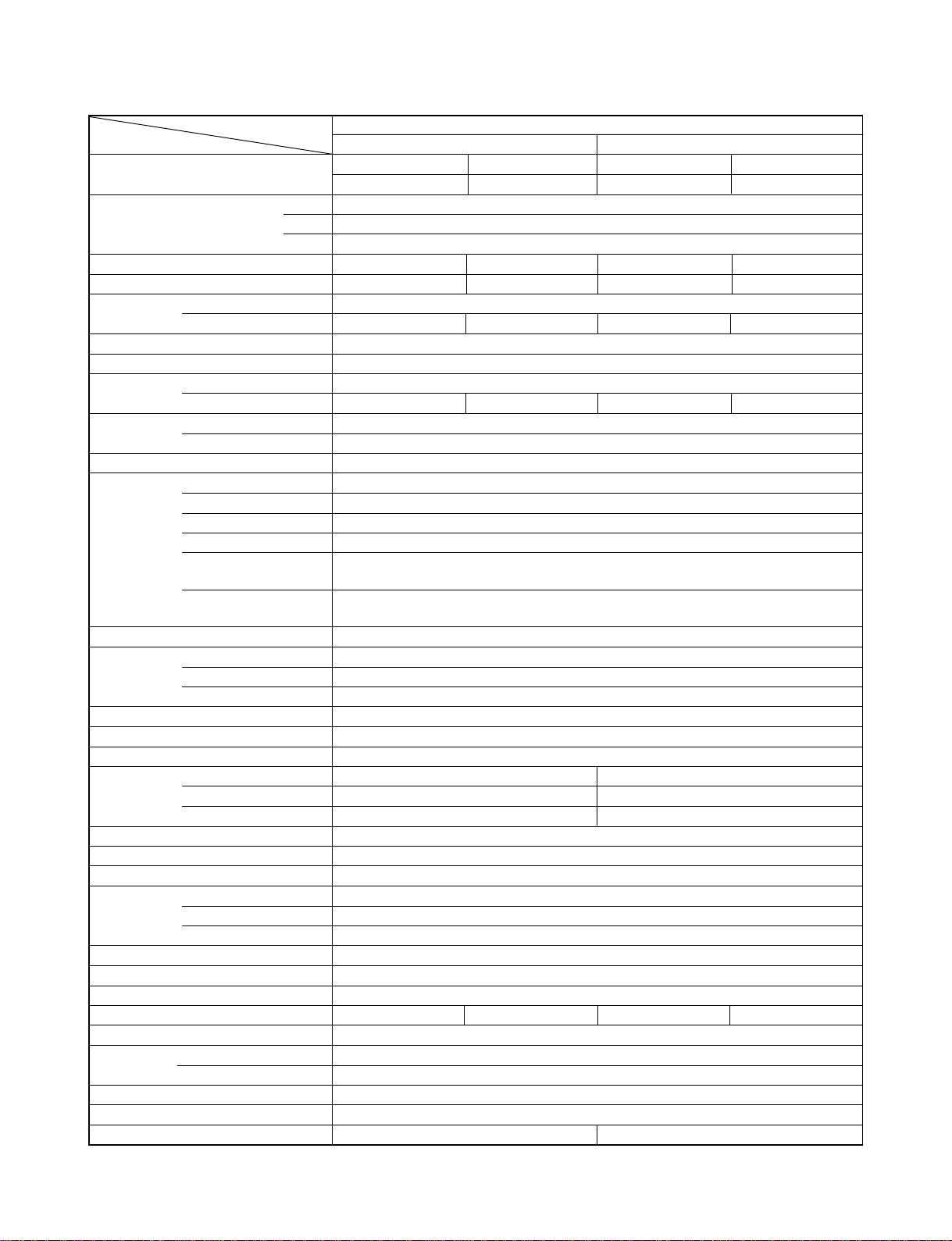
1. SPECIFICATIONS
MODEL RAS-13NKHP-E2 / RAS-13N2AH-E
ITEM Cooling Heating
Capacity
Power source V 220 - 240
Power consumption kW 1.23 1.27 1.26 1.33
Power factor % 99 97 98 96
Running Indoor A 0.15
current Outdoor A 5.50 5.30 5.35 5.15
Starting current A 25
Moisture removal lit/h 2.0
Noise
Refrigerant
Refrigerant control Capillary tube
Interconnection
pipe
INDOOR UNIT RAS-13NKHP-E2
Dimensions Width mm 790
Net weight kg 10
Evaporator type Finned tube
Indoor fan type Cross flow fan
Air-flow volume Medium fan m
Fan motor output W 20
Air filter Honeycomb woven filter with PP frame
OUTDOOR UNIT RAS-13N2AH-E
Dimensions Width mm 780
Net weight kg 37
Condenser type Finned tube
Outdoor fan type Propeller fan
Air-flow volume m
Fan motor output W
Compressor
Safety device Fuse, Overload relay
Louver type Automatic louver
Usable outdoor temperature range °C 15 ~ 43 -10 ~ 24
Indoor (H/M/L) dB 41/35/31
Outdoor (220 - 240 V) dB 49 51 49 51
Name of refrigerant R22
Rated amount kg 1.00
Gas side size mm Æ12.7
Connection type Flare connection
Liquid side size mm Æ6.35
Connection type Flare connection
Maximum length
(One way)
Maximum height
difference
Height mm 275
Depth mm 218
High fan m3/h 630 650
Low fan m3/h 430 490
Height mm 550
Depth mm 270
Model
Output W 1100
kW 3.55
Phase 1Æ
Hz 50
m
m
3
/h 520 550
3
/h 2120
220 V 240 V 240 V 220 V
3.60 4.10 4.15
1
15*
6
2200
42
PH225X2C-4FT
2120 2200
– 3 –

FILE NO. SVM-06001
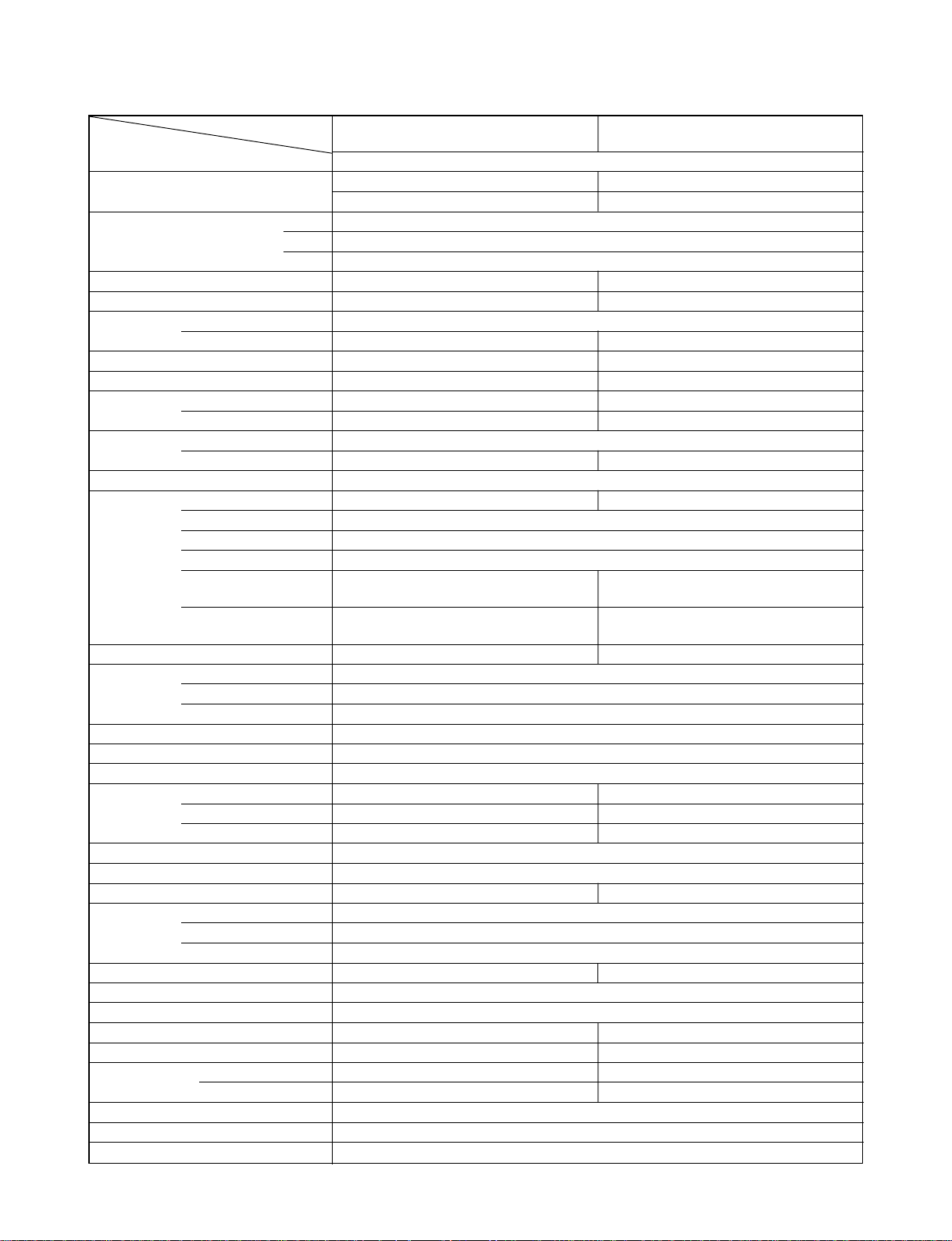
MODEL RAS-13NKP-E2 / RAS-13N2A-E RAS-13NKPX / RAS-13N2AX RAS-12NKPX-V / RAS-12NAX-V
ITEM
Capacity
Power source V 220 - 240
Power consumption kW 1.24 1.28 1.24 1.28 1.24 1.28
Power factor % 98 95 98 95 98 95
Running Indoor A 0.15
current Outdoor A 5.75 5.60 5.75 5.60 5.75 5.60
Starting current A 24
Moisture removal lit/h 2.0
Noise
Refrigerant
Refrigerant control Capillary tube
Interconnection
pipe
INDOOR UNIT
Dimensions Width mm 790
Net weight kg 10
Evaporator type Finned tube
Indoor fan type Cross flow fan
Air-flow volume Medium fan m3/h 520
Fan motor output W 20
Air filter Honeycomb woven filter with PP frame
OUTDOOR UNIT
Dimensions Width mm 780
Net weight kg 34
Condenser type Finned tube
Outdoor fan type Propeller fan
Air-flow volume m3/h 2030
Fan motor output W
Compressor
Safety device Fuse, Overload relay
Louver type Automatic louver
Usable outdoor temperature range °C 15 ~ 43 21 ~ 43
Indoor (H/M/L) dB 41/35/31
Outdoor (220 - 240 V) dB 47 48 47 48 47 48
Name of refrigerant R22
Rated amount kg
Gas side size mm Æ12.7
Connection type Flare connection
Liquid side size mm Æ6.35
Connection type Flare connection
Maximum length
(One way)
Maximum height
difference
Height mm 275
Depth mm 218
High fan m3/h 630
Low fan m3/h 430
Height mm 550
Depth mm 270
Model
Output W 1100
kW 3.70 3.75 3.70 3.75 3.40 3.48
Phase 1Æ
Hz 50
m
m
220 V 240 V 220 V 240 V 220 V 240 V
RAS-13NKP-E2
RAS-13N2A-E RAS-13N2AX
2150
Cooling
0.80
1
15*
6
RAS-13NKPX RAS-12NKPX-V
RAS-12NAX-V
2030 2150 2030 2150
30
PH225X2C-4FT
– 4 –
FILE NO. SVM-06001
MODEL
RAS-13NKP-HX / RAS-13N2A-HX
RAS-10NKP-HX / RAS-10N2A-HX
ITEM Cooling
Capacity
kW 3.65 2.70
220 V 220 V
Phase 1∅
Power source V 220
Hz 50
Power consumption kW 1.05 0.80
Power factor % 98 96
Running Indoor A 0.15
current Outdoor A 4.70 3.65
Starting current A 25 16
Moisture removal lit/h 2.0 1.2
Noise
Refrigerant
Indoor (H/M/L) dB 41/35/31 39/33/26
Outdoor dB 49 46
Name of refrigerant R22
Rated amount kg 0.85 0.75
Refrigerant control Capillary tube
Gas side size mm ∅12.7 ∅9.52
Connection type Flare connection
Liquid side size mm ∅6.35
Interconnection
pipe
INDOOR UNIT
Connection type Flare connection
Maximum length
(One way)
Maximum height
difference
m 15*
m 6 5
1
RAS-13NKP-HX
10*
RAS-10NKP-HX
Height mm 275
Dimensions Width mm 790
Depth mm 218
Net weight kg 10
Evaporator type Finned tube
Indoor fan type Cross flow fan
High fan m3/h 630 610
Air-flow volume Medium fan m
3
/h 520 460
Low fan m3/h 430 340
Fan motor output W 20
Air filter Honeycomb woven filter with PP frame
OUTDOOR UNIT
RAS-13N2A-HX
RAS-10N2A-HX
Height mm 550
Dimensions Width mm 780
Depth mm 270
Net weight kg 36 30
Condenser type Finned tube
Outdoor fan type Propeller fan
Air-flow volume m
3
/h 2120 2030
Fan motor output W 42 30
Compressor
Model RM5515FNE96 RM5510GNE94
Output W 1100 750
Safety device Fuse, Overload relay
Louver type Automatic louver
Usable outdoor temperature range °C 21 ~ 43
1
– 5 –
Note : 1
·
Capacity is based on the following temperature conditions.
FILE NO. SVM-06001
Temperature
Indoor unit inlet air temperature
Outdoor unit inlet air temperature
Note : 2
*1 No need to charge extra refrigerant.
Condition
Cooling Heating
(DB) 27°C20°C
(WB) 19°C15°C
(DB) 35°C7°C
(WB) 24°C6°C
JIS B8615-1
- 6 -
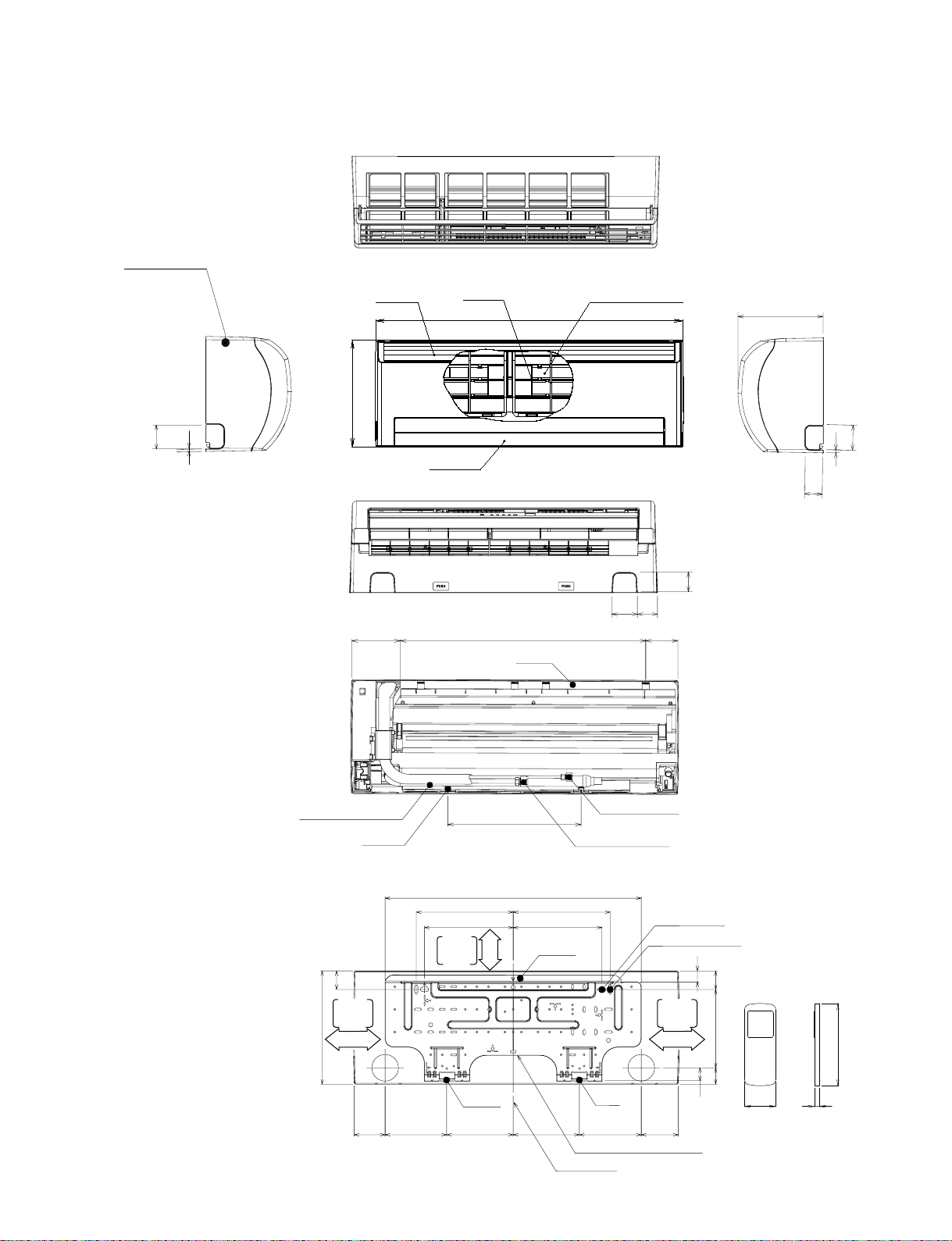
2-1. Indoor Unit
Front panel
FILE NO. SVM-06001
2. CONSTRUCTION VIEWS
60
6
Knock out system
Air inlet
Air filter
Heat exchanger
790
275
Air outlet
64
120 80
590
Hanger
218
60
6
48
Knock out system
48
53
Drain hose (0.54m)
Hanger
45
Minimum
distance
to ceiling
275
170 or more
320
620
235 235
215 215
Minimum
distance
to ceiling
65 or more
Hanger
– 7 –
Connecting pipe (0.43m)
(Flare ∅6.35)
Connecting pipe (0.33m)
(For 10 series ; Flare ∅9.52
For 12,13 series ; Flare ∅12.7)
For stud bolt
(∅8~∅10)
Hanger
For stud bolt (∅6)
Hanger
150150 160160
9090
Installation plate outline
Center line
Minimum
distance
to ceiling
170 or more
26
4519040
32
57 18
Wireless remote control
160
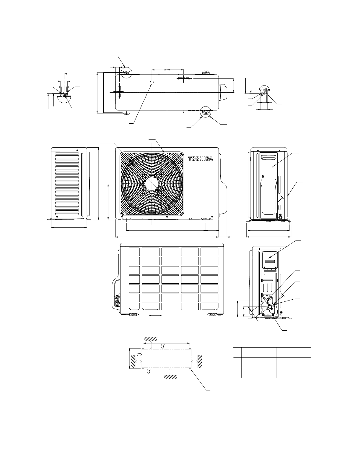
2-2. Outdoor Unit
FILE NO. SVM-06001
A
A
Detail Drawing (Back Leg)
6 Hole
∅
302
310
32.5
600
52
36
270
R15
R5.5
310
302
30 Drain outlet
∅
436
∅
550
265
FAN GUARD
115
125
∅
11 x 14 Hole
2-
∅8-∅
(For
10 anchor bolt)
90
600
780
62
102
∅6 Hole
∅11 x 14 Hole
B
B Detail Drawing (Front Leg)
310
302
36
52
R15
310
330
COVER PV
Z
Electrical
part cover
Installation dimension
B or more
325
100 or more
Z
Air outlet
View
600
Air inlet
A or more
600 or more
120
54
75
∅
11 Long holes (For ∅8-∅10 anchor bolt)
4 x
12,
13 Series
600 mm 400 mm
A
B 100 mm 45 mm
Liquid side
(Flare ∅6.35)
Gas side
(Flare ∅9.52)
10 Series
Gas side
(Flare ∅12.7)
12, 13 Series
Service port
10 Series
– 8 −
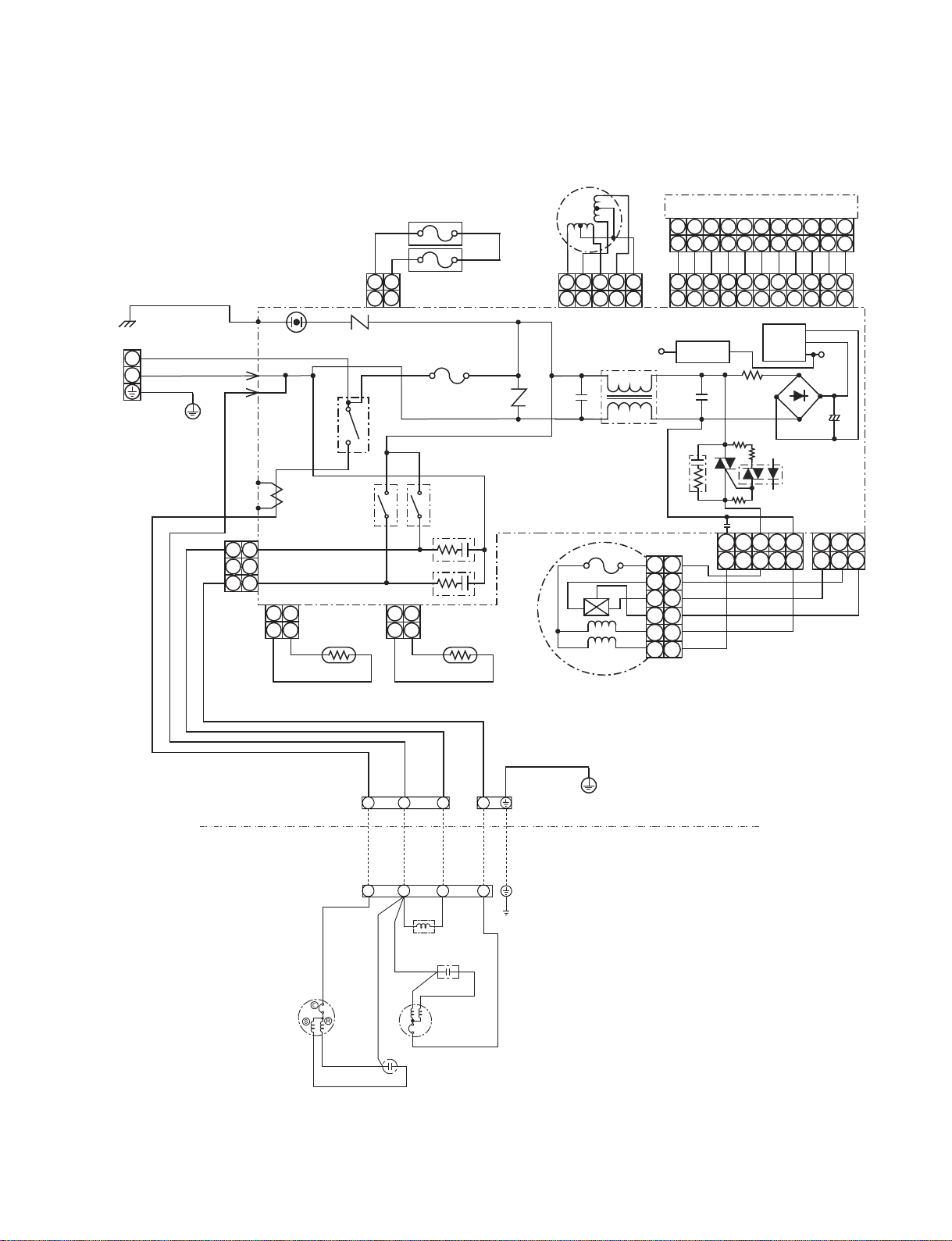
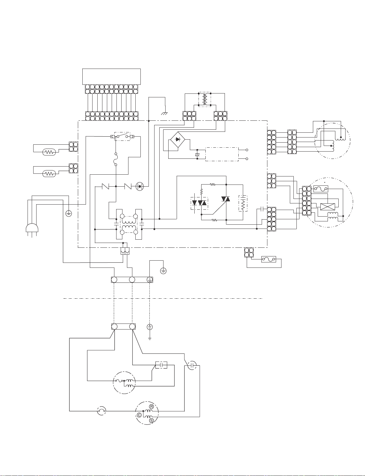
3. WIRING DIAGRAM
3-1. RAS-13NKHP-E2 / RAS-13N2AH-E
FILE NO. SVM-06001
BRW(L)
L
BLU(N)
N
GRN & YEL
Single Phase
220-240V~, 50Hz
BLK
P04
T02
C.T.
131
CN27
73°Cx2
THERMAL FUSE
Louver
Motor
CN25
PNK
SG01
DSA
VARISTOR
BLK
R22
3
4
PNK
112
RY01
2
CN04
T6.3A 250VAC
FUSE F01
MAIN P.C. BOARD
YEL
54321
54321
C01
R21
VARISTOR
YEL
CN07
YEL
YEL
WHI
DC5V
L01
WP-003
RY04RY03
CR01
150°C
1 1
3
CN03
112
BLK
2
BLK
THERMO
SENSOR (TA)
CN01
112
HEAT EXCHANGER
2
BLK
BLK
CR02
SENSOR (TC)
2 2
3 3
4 4
5 5
6 6
INFRARED RAYS RECEIVE
AND INDICATION PARTS
345
1
2
345
1
2
BLU
BLU
BLU
345
2
345
2
Voltage
Regulator
IC03
BLU
R319
R26
BLU
1
1
C02
CR03
C15
5
CN10
BLK
5
GRY
YEL
BRW
RED
WHI
789
6
789
6
BLU
BLU
789
6
789
6
Micro
Power
Module
R25
R27
3 1
3 1
10
11
10
11
BLU
BLU
BLU
10
11
10
11
CN14
DC12V
+
DB01 C63
CN11
1 2 3
1 2 3
WHI
INDOOR
TERMINAL
BLOCK
OUTDOOR
TERMINAL
BLOCK
COMPRESSOR
BLK
BLK
WHI
2
1 4
(L)2(N)
1
BLK
SOLENOID COIL
RED
RED
RED
PNK
WHI
CAPACITOR
BLU
RED
3
3
BLU
CAPACITOR
FAN
MOTOR
BLU
4
WHI
AC FAN MOTOR
GRN&YEL
INDOOR
OUTDOOR
CHASSIS
BLK
− 9 −
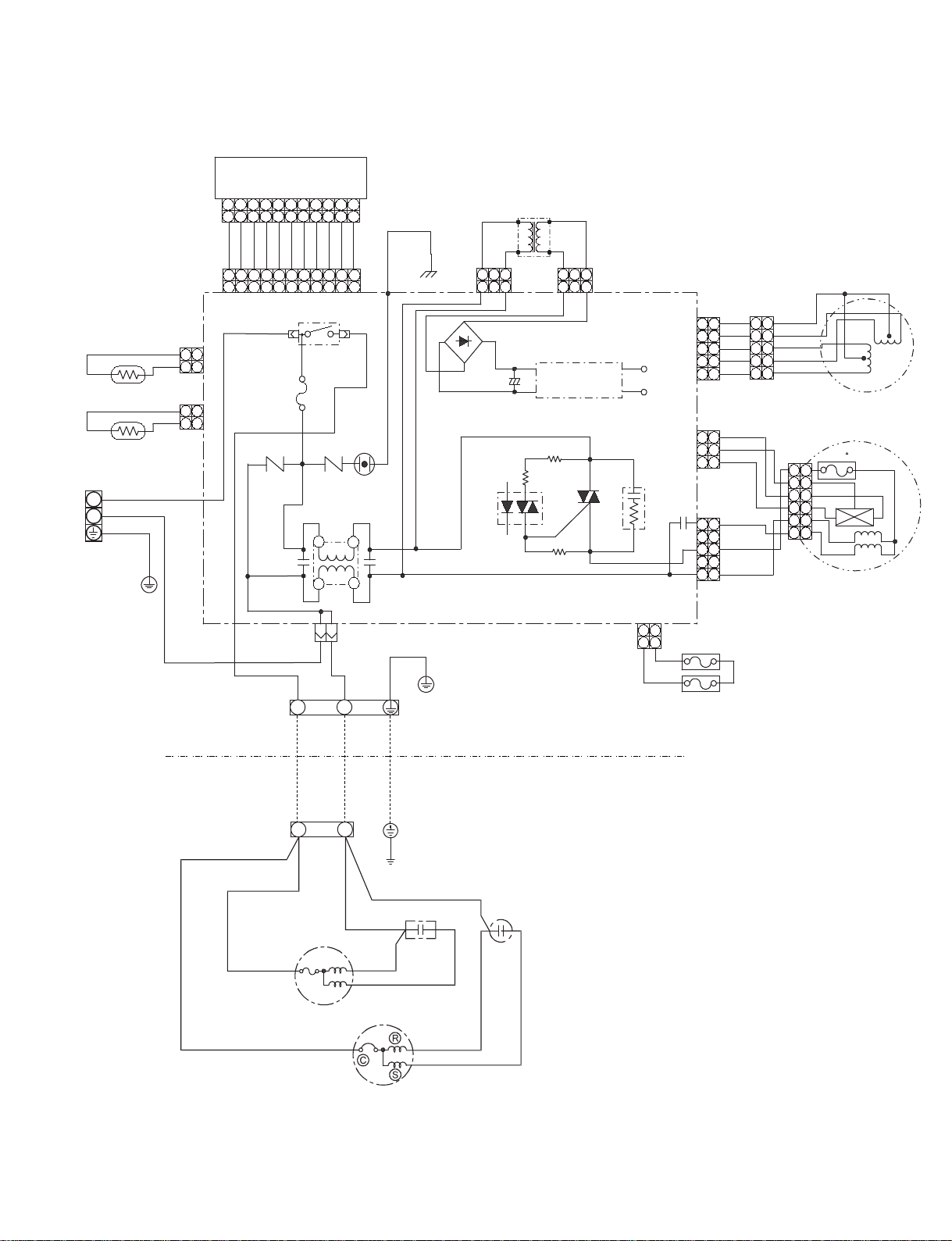
3-2. RAS-13NKP-E / RAS-13N2A-E
Infrared rays receiver
and indication parts.
Heat Exchanger
Sensor (TC)
Thermo Sensor (TA)
BRW(L)
L
BLU(N)
N
GRN & YEL
Single Phase
220-240V~, 50Hz
CN01
121
CN03
121
CN25
CN14
2
2
1
1
BLU
1
1
2
BLU
2
43
432
BLU
BLU
432
43
F01
T6.3 A
250 VAC
8
6
7
5
8
6
7
5
BLU
BLU
BLU
BLU
BLU
8
6
7
5
6587
3
RY01
R21 R22
2
2
C15
3
10
9 11
10
9
BLU
10
9
10
9
L01
FILE NO. SVM-06001
RED
TRANS (T T-10)
WHI
113
CN05 CN06
3
DB50
C50
+
IC03
R46
BLU
113
Regulator
circuit
R47
R48
GRY
3
MCC-920
DC 12 V
DC 5 V
CN07
1
2
3
4
5
WHI
1
YEL
YEL
YEL
YEL
1
2
2
3
3
4
4
5
5
1
2
3
4
5
Louver motor
CN11
YEL
1
1
GRY
2
2
D38
CR03
C58
3
CN10
5
3
1
BRW
3
WHI
5
BLK
3
RED
1
1
2
3
4
5
6 6
150 C
1
2
3
4
5
Indoor FAN motor
11
WHI
11
BLK
11
P04
4
SG01
DSA
1
C01
4
CN31
INDOOR
TERMINAL
BLK
1
BLOCK
OUTDOOR
TERMINAL
BLOCK
BLK BLK RED
1(L) 2(N)
FAN MOTOR
WHI
2
RED
WHI
COMPRESSOR
GRN&YEL
CHASSIS
CAPACITOR
RED
PNK
WHI
INDOOR
OUTDOOR
CAPACITOR
CN04
PNK
112
2
PNK
73 °Cx2
TEMP FUSE
− 10 −

3-3. RAS-13NKPX / RAS-13N2AX
RAS-12NKPX-V / RAS-12NAX-V
Infrared rays receiver
and indication parts.
2
43
6
7
432
BLU
BLU
BLU
432
2
43
F01
T6.3 A
250 VAC
R21 R22
5
6
7
5
BLU
BLU
BLU
6
7
5
6587
3
C15
Heat Exchanger
Sensor (TC)
Thermo Sensor (TA)
BRW (L)
BLU (N)
GRN&YEL
Single Phase
220-240V~, 50Hz
CN01
121
CN03
121
CN25
CN14
2
2
1
1
BLU
1
1
8
8
BLU
8
RY01
2
3
9 11
9
BLU
9
9
L01
2
FILE NO. SVM-06001
10
10
11
BLU
WHI
10
11
10
BLK
11
P04
4
SG01
DSA
1
C01
4
RED
TRANS (T T-10)
WHI
113
CN05 CN06
3
DB50
C50
+
IC03
R46
BLU
113
Regulator
circuit
R47
R48
GRY
3
MCC-920
DC 12 V
DC 5 V
CN07
1
2
3
4
5
WHI
1
YEL
YEL
YEL
YEL
1
2
2
3
3
4
4
5
5
1
2
3
4
5
Louver motor
CN11
YEL
1
1
GRY
2
2
D38
CR03
C58
3
CN10
5
3
1
BRW
3
WHI
5
BLK
3
RED
1
1
2
3
4
5
6 6
150 C
1
2
3
4
5
Indoor FAN motor
CN31
INDOOR
TERMINAL
BLK
1
BLOCK
OUTDOOR
TERMINAL
BLOCK
BLK BLK RED
1(L) 2(N)
FAN MOTOR
WHI
2
RED
WHI
COMPRESSOR
GRN&YEL
CHASSIS
CAPACITOR
RED
PNK
WHI
INDOOR
OUTDOOR
CAPACITOR
CN04
PNK
112
2
PNK
TEMP FUSE
73 °C
− 11 −

3-4. RAS-13NKP-HX / RAS-13N2A-HX
Infrared rays receiver
and indication parts.
Heat Exchanger
Sensor (TC)
Thermo Sensor (TA)
Single Phase
220-240V~, 50Hz
GRN&YEL
BLU (N)
BRW (L)
CN01
121
CN03
121
CN25
CN14
2
2
2
1
1
BLU
BLU
BLU
1
2
1
250 VAC
INDOOR
TERMINAL
BLOCK
43
432
BLU
432
43
F01
T6.3 A
8
6
7
5
8
6
7
5
BLU
BLU
BLU
BLU
BLU
8
6
7
5
6587
3
RY01
R21 R22
2
2
C15
3
CN31
BLK
1
10
9 11
10
9
BLU
10
9
10
9
L01
WHI
2
4
11
WHI
11
11
1
4
SG01
DSA
BLK
P04
C01
GRN&YEL
TRANS (T T-10)
RED
WHI
113
3
DB50
C50
IC03
INDOOR
OUTDOOR
GRY
BLU
113
CN05 CN06
+
3
Regulator
circuit
R47
R46
D38
R48
CN04
PNK
FILE NO. SVM-06001
MCC-920
CR03
112
DC 12 V
DC 5 V
2
PNK
CN07
1
2
3
4
5
CN11
1
2
3
CN10
C58
5
3
1
TEMP FUSE
73 °C
WHI
1
YEL
YEL
YEL
YEL
YEL
GRY
BRW
WHI
BLK
RED
1
2
2
3
3
4
4
5
5
1
2
3
4
5
1
2
3
5
3
1
Louver motor
150 C
1
1
2
2
3
3
4
4
5
5
6 6
Indoor FAN motor
OUTDOOR
TERMINAL
BLOCK
BLK BLK RED
OVERLOAD RELAY
1(L) 2(N)
FAN MOTOR
BLK
CAPACITOR
RED
WHI
COMPRESSOR
CHASSIS
RED
CAPACITOR
PNK
WHI
− 12 −
3-5. RAS-10NKP-HX / RAS-10N2A-HX
Infrared rays receiver
and indication parts.
Heat Exchanger
Sensor (TC)
Thermo Sensor (TA)
Single Phase
220-240V~, 50Hz
GRN&YEL
BLU (N)
BRW (L)
CN01
121
CN03
121
CN25
CN14
2
2
2
1
1
BLU
BLU
BLU
1
2
1
250 VAC
INDOOR
TERMINAL
BLOCK
43
432
BLU
432
43
F01
T6.3 A
8
6
7
5
8
6
7
5
BLU
BLU
BLU
BLU
BLU
8
6
7
5
6587
3
RY01
R21 R22
2
2
C15
3
CN31
BLK
1
10
9 11
10
9
BLU
10
9
10
9
L01
WHI
2
4
11
WHI
11
11
1
4
SG01
DSA
BLK
P04
C01
GRN&YEL
TRANS (T T-10)
RED
WHI
113
3
DB50
C50
IC03
INDOOR
OUTDOOR
GRY
BLU
113
CN05 CN06
+
3
Regulator
circuit
R47
R46
D38
R48
CN04
PNK
FILE NO. SVM-06001
MCC-920
CR03
112
DC 12 V
DC 5 V
2
PNK
CN07
1
2
3
4
5
CN11
1
2
3
CN10
C58
5
3
1
TEMP FUSE
73 °C
WHI
1
YEL
YEL
YEL
YEL
YEL
GRY
BRW
WHI
BLK
RED
1
2
2
3
3
4
4
5
5
1
2
3
4
5
1
2
3
5
3
1
Louver motor
150 C
1
1
2
2
3
3
4
4
5
5
6 6
Indoor FAN motor
OUTDOOR
TERMINAL
BLOCK
BLK BLK RED
OVERLOAD RELAY
1(L) 2(N)
FAN MOTOR
BLK
CAPACITOR
RED
WHI
COMPRESSOR
CHASSIS
RED
CAPACITOR
PNK
WHI
− 13 −
FILE NO. SVM-06001
4. SPECIFICATION OF ELECTRICAL PARTS
4-1. Indoor Unit (RAS-13NKHP-E2)
No. Parts name Type Specifications
1 Fan motor (for indoor) SKF-220-20-4A-1 AC Motor with 150 C thermo fuse
2 Thermo sensor (TA-sensor) 10k at 25 C
3 Micro Power Module (M01)
4 Microcontroller unit (IC30) TMP87CM40AN
5 Heat exchanger sensor
(TC-sensor)
6 Line filter (L01) LC*SS11V-06270 27mH, 600mA
7 Bridge rectifier (DB01) D3SBA60 4A, 600 V
8 Capacitor (C63) KMH400VSSN47M22S 47mF, 400 V
9 Fuse (F01) BET 6.3A T6.3A, 250VAC
10 Varistor (R21, R22) TND15G561K 560 V
11 Resistor (R319) RF-2TK5R6 5.6 , 2 W
12 Louver motor MP24Z 12VDC
13 Relay (Comp., RY01) DI1U Rating 25A/AC250 V, 3-48VDC
14 Relay (Fan, RY03) G5NB-1A Rating 3A/AC250 V, 12VDC
15 Relay (Solenoide, RY04) G5NB-1A Rating 3A/AC250 V, 12VDC
µRM1260V
W
DC 390V, Secondary DC 12V
W
10k at 25 C
W
°
°
°
4-2. Outdoor Unit (RAS-13N2AH-E)
No. Parts name Type Specifications
Output (Rated) 1100 W, 2 poles, 1 phase, 220 - 240 V, 50Hz
1 Compressor PH225X2C-4FT Winding resistance ( ) C-R C-S
°
(at 20 C) 2.35 3.22
Output (Rated) 42 W, 6 poles, 1 phase, 220 - 240 V, 50Hz
2 Fan motor (for outdoor) HF-240-42A Winding resistance ( ) Red-Black White-Black
°
(at 20 C) 176.2 290.5
Running capacitor
3
(for fan motor)
Running capacitor
4
(for compressor)
DS451155NPQB AC 450 V, 1.5mF
RS44B356U0125S AC 440 V, 35mF
W
W
- 14 -
FILE NO. SVM-06001
4-3. Indoor Unit (RAS-13NKP-E2, RAS-13NKPX, RAS-12NKPX-V,
RAS-13NKP-HX, RAS-10NKP-HX)
No. Parts name Type Specifications
1 Fan motor (for indoor) SKF- 220-20-4A-1 AC Motor with 150 C thermo fuse
2 Thermo sensor (TA-sensor) 10k at 25 C
3 Transformer
4 Microcontroller unit (IC30) TMP87CM40AN
5 Heat exchanger sensor
(TC-sensor)
6 Line filter (L01) *SS11V-06270 27mH, 600mA
7 Bridge rectifier (DB50) KBP06M/51 1.5A, 600 V
8 Capacitor (C50) PF1E222MNN1625 2200mF, 25 V
9 Fuse (F01) BET6.3A T6.3A, 250VAC
10 Varistor (R21, R22) TND15G561K 560 V
11 Louver motor MP24Z 12VDC
12 Relay (Comp., RY01) DI1U Rating 25A/AC250 V, 3~48VDC
TT-10
W
10k at 25 C
W
°
°
°
4-4. Outdoor Unit (RAS-13N2A-E, RAS-13N2AX, RAS-12NAX-V)
No. Parts name Type Specifications
Output (Rated) 1100 W, 2 poles, 1 phase, 220 - 240 V, 50Hz
1 Compressor
2 Fan motor (for outdoor)
Running capacitor
3
Running capacitor
4
(for compressor)
PH225X2C-4FT
HF-240-30B
or
WLF-240-30A
DS451155NPQB AC 450 V, 1.5µ
RS44B356U0125S AC 440 V, 35 F
Winding resistance (W) C-R C-S
°
(at 20 C) 2.35 3.22
Output (Rated) 30 W, 6 poles, 1 phase, 220 - 240 V, 50Hz
Winding resistance (W) Red-Black White-Black
°
(at 20 C) 245 or 237 388 or 380
m
- 15 -
4-5. Outdoor Unit (RAS-13N2A-HX)
FILE NO. SVM-06001
No.
1 Compressor RM5515FNE96 Winding resistance (W) C-R C-S
2 Fan motor (for outdoor)
Running capacitor
3
(for fan motor)
Running capacitor
4
(for compressor)
Overload relayP
5
ar
ts name Type Specifications
Output (Rated) 1100 W, 2 poles, 1 phase, 220 - 240 V, 50Hz
(at 20°C) 2.43 3.78
HF-240-42A
DS451155NPQB AC 450 V, 1.5 F
RS44B256U0213S AC 440 V, 25 F
LPAP960B
Output (Rated) 20 W, 6 poles, 1 phase, 220 - 240 V, 50Hz
Winding resistance (W) Red-Black White-Black
(at 20°C) 290.5
m
m
U/T : 6.1A (80°C), OPEN : 135±5°C, CLOSE : 78±11°C
176.2
4-6. Outdoor Unit (RAS-10N2A-HX)
No.
1 Compressor RM5510GNE94 Winding resistance (W) C-R C-S
2 Fan motor (for outdoor)
Running capacitor
3
(for fan motor)
Running capacitor
4
(for compressor)
Overload relayP
5
ar
ts name Type Specifications
Output (Rated) 750 W, 2 poles, 1 phase, 220 - 240 V, 50Hz
(at 20°C) 3.710 4.099
HF-240-30B
DS451155NPQB AC 450 V, 1.5 F
RS44B256U0213S AC 440 V, 25 F
LPAP960B
Output (Rated) 20 W, 6 poles, 1 phase, 220 - 240 V, 50Hz
Winding resistance (W) Red-Black White-Black
(at 20°C) 388
m
m
U/T : 6.1A (80°C), OPEN : 135±5°C, CLOSE : 78±11°C
245
- 16 -
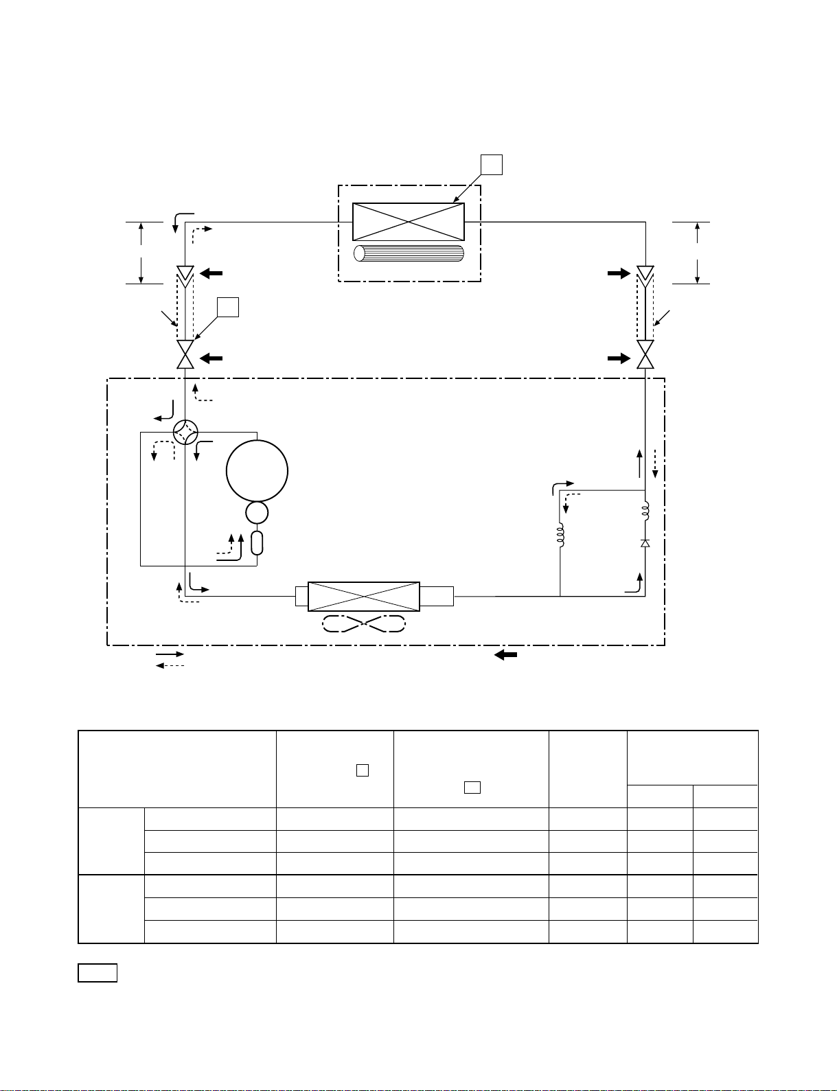
5. REFRIGERATION CYCLE DIAGRAM
5-1. RAS-13NKHP-E2 / RAS-13N2AH-E
FILE NO. SVM-06001
Indoor unit
Cooling
0.39 m
(Connecting pipe)
Æ12.7
O.D.:12.7 mm O.D.:6.35 mm
Cooling
Heating
Heating
P
Packed valve
(Æ12.7)
Heating
4-way valve
Cooling
Compressor
PH225X2C-4FT
Accumulator
Heat exchanger
Cross flow fan
T1
Capillary tube
Æ1.5 x 900
Packed valve
(Æ6.35)
Capillary tube
Æ1.0 x 800
l
0.49 m
(Connecting pipe)
Æ6.35
l
Heat exchanger
Refrigerant
R22 : 1.00 kg.
Cooling
Heating
Propeller fan
Outdoor unit
Mark ( ) means check points of Gas Leak.
Ambient temp.
50Hz
Standard
pressure
(MPaG)
P
Surface temp. of heat
exchanger interchanging
pipe
T1
(°C)
Fan speed
(indoor)
conditions DB/WB
(°C)
Indoor Outdoor
Standard 1.84 46.0 High 20/15 7/6
Heating Overload*1 2.00 ~ 2.42 52.0 ~ 59.0 Low 27/- 24/18
Low temperature 1.50 38.0 High 20/
-
-10/-10
Standard 0.49 10.0 High 27/19 35/24
Cooling Overload 0.60 15.0 High 32/23 43/26
Low temperature 0.45 2.0 Low 21/15 21/15
Note
Measure the heat exchanger temperature at the center of U-bend. (By means of TC sensor)
·
·
*1 During heating overload operation, a value for the high temperature limit control operation is included.
- 17 -
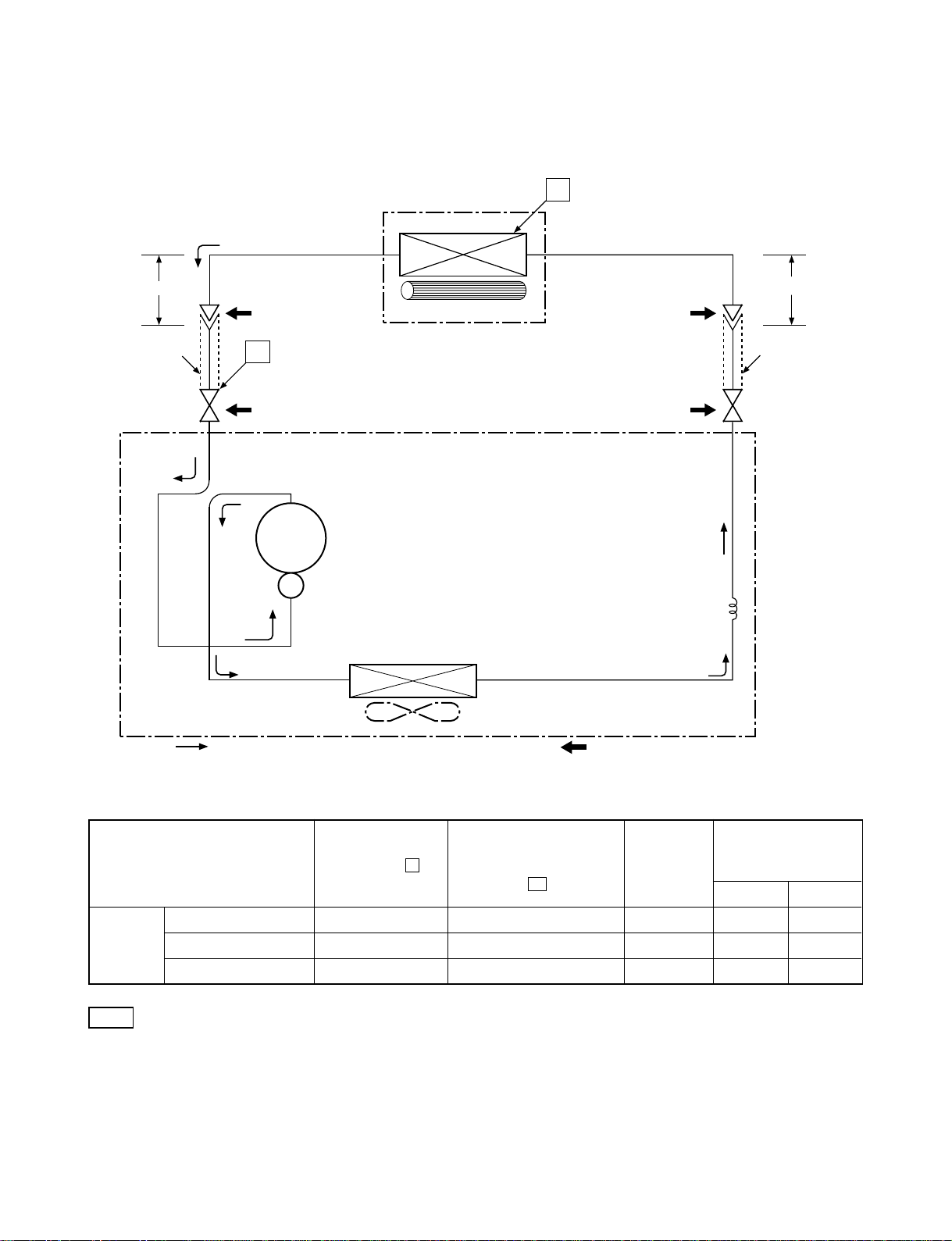
5-2. RAS-13NKP-E2 / RAS-13N2A-E
RAS-13NKPX / RAS-13N2AX
RAS-12NKPX-V / RAS-12NAX-V
FILE NO. SVM-06001
Indoor unit
Cooling
0.39 m
(Connecting pipe)
Æ12.7
O.D.:12.7 mm O.D.:6.35 mm
Cooling
Packed valve
Cooling
P
(Æ12.7)
Compressor
PH225X2C-4FT
Heat exchanger
Cross flow fan
T1
Packed valve
(Æ6.35)
Capillary tube
Æ1.7 x 1000
0.49 m
(Connecting pipe)
Æ6.35
l
Heat exchanger
Refrigerant
R22 : 0.80 kg.
Cooling
Propeller fan
Outdoor unit
Mark ( ) means check points of Gas Leak.
Ambient temp.
50Hz
Standard
pressure
(MPaG)
P
Surface temp. of heat
exchanger interchanging
pipe
T1
(°C)
Fan speed
(indoor)
conditions DB/WB
(°C)
Indoor Outdoor
Standard 0.48 9.0 High 27/19 35/24
Cooling Overload 0.59 15.0 High 32/23 43/26
Low temperature 0.45 2.0 Low 21/15 21/15
Note
· Measure the heat exchanger temperature at the center of U-bend. (By means of TC sensor)
− 18 −

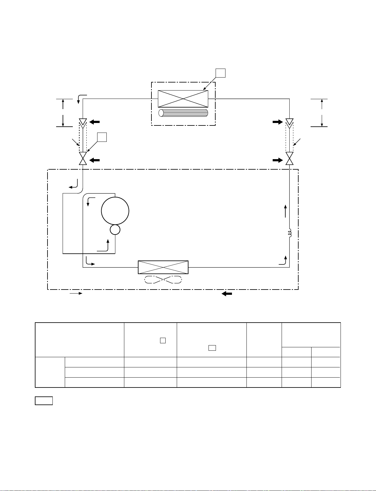
5-3. RAS-13NKP-HX / RAS-13N2A-HX
FILE NO. SVM-06001
Indoor unit
Cooling
0.39 m
(Connecting pipe)
∅12.7
O.D.:12.7 mm O.D.:6.35 mm
Cooling
Cooling
P
Packed valve
∅
( 12.7)
Compressor
RM5515FNE96
Heat exchanger
Cross flow fan
T1
0.49 m
(Connecting pipe)
∅6.35
Packed valve
(∅6.35)
Capillary tube
∅1.7 x 800l
Heat exchanger
Refrigerant
R22 : 0.85 kg.
Cooling
Propeller fan
Outdoor unit
Mark ( ) means check points of Gas Leak.
Ambient temp.
50Hz
Standard
pressure
(MPaG)
P
Surface temp. of heat
exchanger interchanging
pipe
T1
(°C)
Fan speed
(indoor)
conditions DB/WB
(°C)
Indoor Outdoor
Standard 0.48 9.0 High 27/19 35/24
Cooling Overload 0.59 15.0 High 32/23 43/26
Low temperature 0.45 2.0 Low 21/15 21/15
Note
•Measure the heat exchanger temperature at the center of U-bend. (By means of TC sensor)
− 19 −
5-4. RAS-10NKP-HX / RAS-10N2A-HX
FILE NO. SVM-06001
Indoor unit
Cooling
0.39 m
(Connecting pipe)
9.52
∅
O.D.:9.52 mm O.D.:6.35 mm
Cooling
Packed valve
Cooling
P
(∅9.52)
Compressor
RM5510GNE94
Heat exchanger
Cross flow fan
T1
Packed valve
(∅6.35)
Capillary tube
1.5 x 1000l
∅
0.49 m
(Connecting pipe)
6.35
∅
Heat exchanger
Refrigerant
R22 : 0.75 kg.
Cooling
Propeller fan
Outdoor unit
Mark ( ) means check points of Gas Leak.
Ambient temp.
50Hz
Standard
pressure
(MPaG)
P
Surface temp. of heat
exchanger interchanging
pipe
T1
(°C)
Fan speed
(indoor)
conditions DB/WB
(°C)
Indoor Outdoor
Standard 0.56 12.0 High 27/19 35/24
Cooling Overload 0.68 17.0 High 32/23 43/26
Low temperature 0.48 5.0 Low 21/15 21/15
Note
•Measure the heat exchanger temperature at the center of U-bend. (By means of TC sensor)
− 20 −
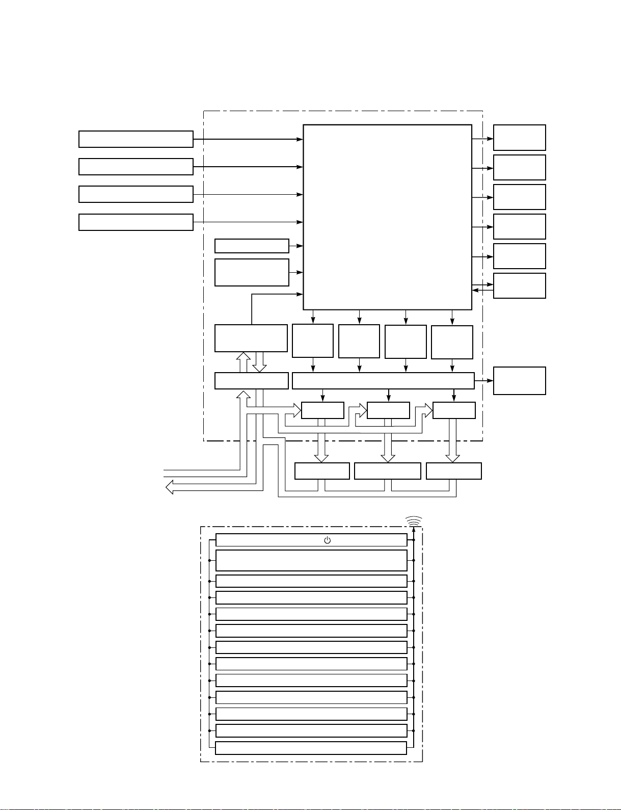
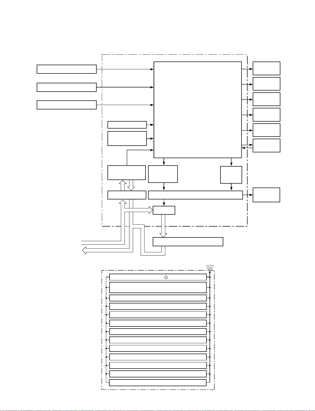
6. CONTROL BLOCK DIAGRAM
6-1. RAS-13NKHP-E2 / RAS-13N2AH-E
FILE NO. SVM-06001
Heat Exchange sensor
Thermo. Sensor
Current Sensor
(Compressor Current)
Infrared Rays Signal Reciver
Main Unit Control Panel
Functions
• Louver Control
•3-minutes Delay at Restart
for Compressor
Initiallizing Circuit
Clock Frequency
Oscillator Circuit
Power Supply
Circuit
Noise Filter Relay Driver, Louver Driver
•Motor Revolution Control
•Processing
(Temperature Processing)
•Timer
Compressor
ON/OFF
Signal
Outdoor Fan
Relay
RY01
M.C.U.
ON/OFF
Signal
Relay
4-Way Valve
ON/OFF
Signal
RY03
Operation
Display
Timer
Display
Filter Sign
Display
Hi Power
Sign Display
PRE DEF.
Sign Display
Indoor Fan
Motor
Louver
ON/OFF
Signal
Louver
Motor
Relay
RY04
220-240 V~, 50Hz
REMOTE CONTROL
Compressor 4-Way Valve
Remote Control
Outdoor Fan Motor
Operation ( )
Operation Mode Selection
AUTO, COOL, DRY, HEAT, FAN ONLY
Temperature Setting
Fan Speed Selection
ON TIMER Setting
OFF TIMER Setting
Louver Auto Swing
Louver Direction Setting
ECO
Hi power
TIMER 1.3.5.9H
COMFORT SLEEP
QUIET
Infrared Rays
− 21 −
FILE NO. SVM-06001
6-2. RAS-13NKP-E2 / RAS-13N2A-E, RAS-13NKPX / RAS-13N2AX, RAS-12NKPX-V / RAS-12NAX-V
RAS-13NKP-HX / RAS-13N2A-HX, RAS-10NKP-HX / RAS-10N2A-HX
Main Unit Control Panel M.C.U.
Heat Exchange sensor
Thermo. Sensor
Infrared Rays Signal Reciver
Initiallizing Circuit
Clock Frequency
Oscillator Circuit
Functions
• Louver Control
•3-minutes Delay at Restart
for Compressor
•Motor Revolution Control
•Processing
(Temperature Processing)
•Timer
Operation
Display
Timer
Display
Filter Sign
Display
Hi Power
Sign Display
Fan Only
Sign Display
Indoor Fan
Motor
220-240 V~, 50Hz
REMOTE CONTROL
Power Supply
Circuit
Noise Filter Relay Driver, Louver Driver
Operation Mode Selection
AUTO, COOL, DRY, FAN ONLY
Louver Direction Setting
Compressor
ON/OFF
Signal
Relay
RY01
Compressor, Outdoor Fan Motor
Remote Control
Operation ( )
Operation ( )
Temperature Setting
Fan Speed Selection
ON TIMER Setting
OFF TIMER Setting
Louver Auto Swing
ECO
Hi power
TIMER 1.3.5.9H
Infrared Rays
Louver
ON/OFF
Signal
Louver
Motor
COMFORT SLEEP
QUIET
− 22 −
7. OPERATION DESCRIPTION
FILE NO. SVM-06001
7-1. Outline of Air Conditioner Control
This is a fixed capacity type air conditioner, which uses
AC motor for an indoor fan. The AC motor drive
circuit is mounted in the indoor unit. And electrical
parts which driving the compressor and the outdoor
fan motor, are mounted in the outdoor unit.
The air conditioner is controlled by the controller
mounted in the indoor unit. The controller operates all
components based on the commands transmitted from
the remote control and the feedback data of the sensor
is as follow:
• The temperature measurement at the air inlet of
the indoor heat exchanger by the indoor
temperature sensor
•The temperature measurement at the indoor
heat exchanger by the indoor heat exchanger
temperature sensor
• Indoor fan motor operation control
• Louver motor control
• LED display control
• Outdoor fan motor operation control
• 4-WAYS-VALVE operation control
(Heat pump model only)
• Compressor operation control
• Receiving the information of the operation
status and judging the information or the
indication of errors
Table 7-1-1
7-1-1. Louver control
(1) Vertical air flow louver
Position of veritcal air flow louver is automatically
controlled according to the operation mode.
Besides, position of vertical air flow louver can be
arbitrarily set by pressing [FIX] button.
The louver position which is set by [FIX] button is
stored in the microcontroller, and the louver is
automatically set at the stored position for the next
operation.
(2) Swing
If [SWING] button is pressed when the indoor unit
is in operation, the vertical air flow louver starts
swinging. When [SWING] button is pressed again,
it stops swinging.
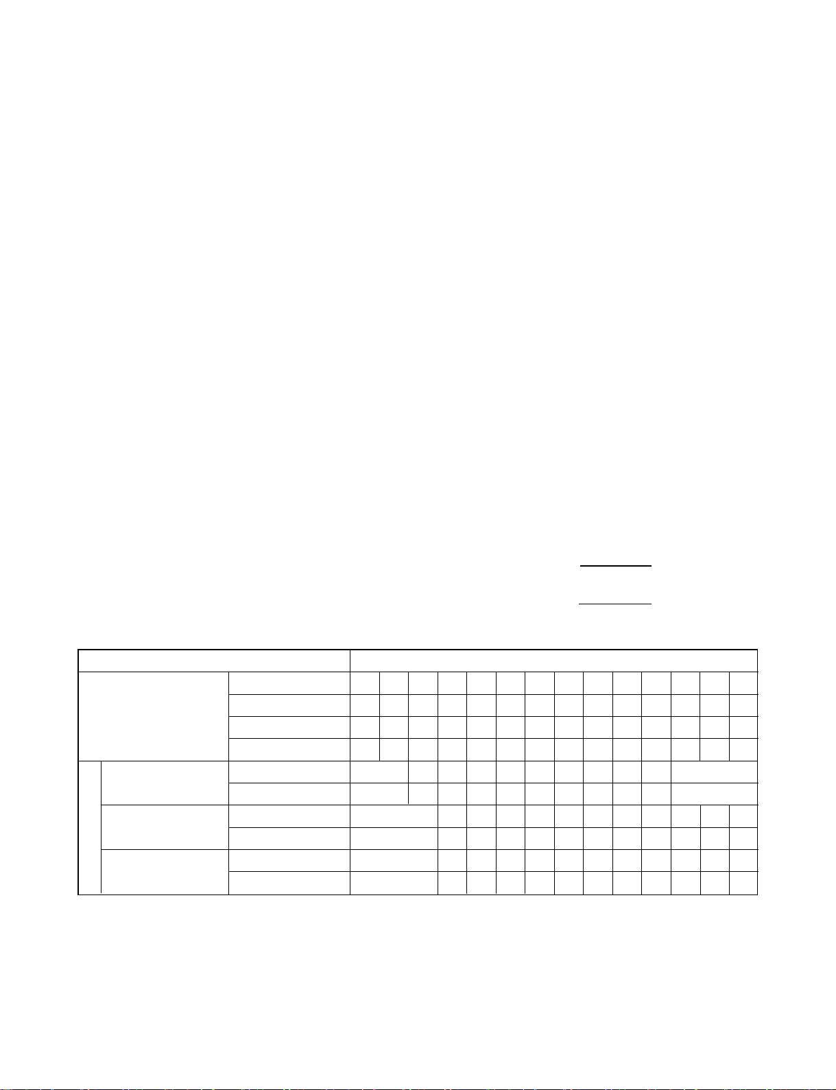
7-1-2. Indoor fan control (AC Fan motor)
(1) The indoor fan is operated by the stepless speed
change AC motor.
(2) For air flow level, speed of the indoor fan motor is
controlled in five steps (LOW, LOW
+
, MED, MED
and HIGH). If AUTO mode is selected, the fan
motor speed is automatically controlled by the
difference between the preset temperature and
the room temperature.
LOW
=
LOW+MED
+
2
MED+=
MED+HIGH
2
+
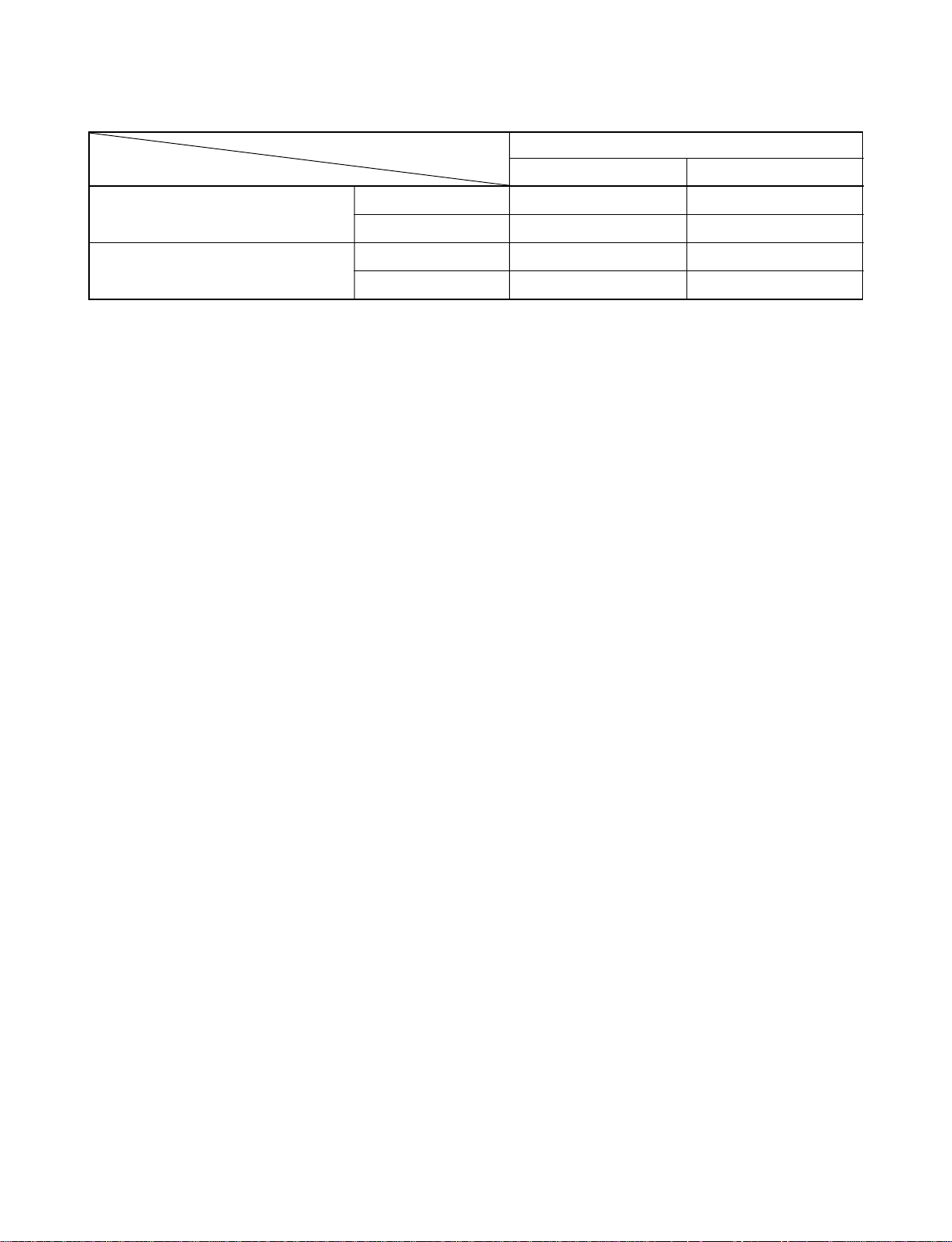
OPERATION
MODE
RAS-10NK Series
RAS-13NK Series
RAS-12NK Series
Model
RAS-13NKH Series
FAN TA P
Cooling UH H M L L- UL SL
Fan only H M L L-
Dry M L L- UL SL
Heat UH H M L L- UL SL
rpm 1350 1250 1050 1000 950 900 800 750 700 650
Air flow volume (m3/h) 650 610 490 460 430 400 340 310 280 250
rpm
Air flow volume (m3/h)
rpm
Air flow volume (m3/h)
1300
630
1350 1300 1150 1100 1050 1000 950 900 850 750
650 630 550 520 490 460 430 400 370 310
1350 1300 1150 1100 1050 1020 950 900 850 750
650 630 550 520 490 470 430 400 370 310
800
340
800
340
700
280
700
280
− 23 −
 Loading...