

Toshiba RAS-13G2KVP-E, RAS-13G2AVP-E, RAS-10G2KVP-E, RAS-10G2AVP-E, RAS-16G2KVP-E Service Manual
...
SERVICE MANUAL
Indoor Unit Outdoor Unit
<High Wall, Heat Pump Type> <Heat Pump Type>
FILE NO. SVM-14017
SPLIT TYPE
RAS-10G2KVP-E / RAS-10G2AVP-E
RAS-13G2KVP-E / RAS-13G2AVP-E
RAS-16G2KVP-E / RAS-16G2AVP-E
R410A
May, 2014

FILE NO. SVM-14017
CONTENTS
1. SAFETY PRECAUTIONS .......................................................................... 2
2. SPECIFICATIONS ..................................................................................... 5
3. REFRIGERANT R410A ............................................................................. 7
4. CONSTRUCTION VIEWS ........................................................................ 15
5. WIRING DIAGRAM .................................................................................. 17
6. SPECIFICATIONS OF ELECTRICAL PARTS ......................................... 18
7. REFRIGERANT CYCLE DIAGRAM ........................................................ 19
8. CONTROL BLOCK DIAGRAM ................................................................ 22
9. OPERATION DESCRIPTION................................................................... 24
10.
11.
12.
13.
INSTALLATION PROCEDURE ................................................................ 62
HOW TO DIAGNOSE THE TROUBLE...................................................... 79
HOW TO REPLACE THE MAIN PARTS.................................................. 104
EXPLODED VIEWS AND PARTS LIST .................................................. 122
– 1 –
FILE NO. SVM-14017
1. SAFETY PRECAUTIONS
Installing, staring up, and servicing air-conditioning equipment can be hazardous due to system pressures, electrical
components, and equipment location (roofs, elevated structures, etc.).
Only trained, qualified installers and service mechanics should install, start-up, and service this equipment.
Untrained personnel can perform basic maintenance functions such as cleaning coils. All other operations should be
performed by trained service personnel.
When working on the equipment, observe precautions in the literature and on tags, stickers, and labels attached to the
equipment.
Follow all safety codes, Wear safety glasses and work gloves. Keep quenching cloth and fire extinguisher near by
when brazing. Use care in handling, rigging, and setting bulky equipment.
Read these instructions thoroughly and follow all warnings or cautions included in literature and attached to the unit.
Consult local building codes and National Electrical Code (NEC) for special requirements. Recognize safety information.
This is the safety-alert symbol
potential for personal injury. Understand these signal words : DANGER, WARNING, and CAUTION. These words are
used with the safety-alert symbol.
DANGER identifies the most serious hazards which will result in severs personal injury or death. WARNING signifies
hazards which could result in personal injury or death. CAUTION is used to identify unsafe practices which may result
in minor personal injury or product and property damage. NOTE is used to highlight suggestions which will result in
enhanced installation, reliability, or operation.
! . When you see this symbol on
the unit and in instructions or manuals, be alert to the
• Before installation, please read these precautions for safety carefully.
• Be sure to follow the precautions provided here to avoid safety risks. The symbols and their meanings are shown below.
WARNING : It indicates that incorrect use of this unit may cause severe injury or death.
CAUTION : FAILURE TO FOLLOW THIS CAUTION may result in equipment damage or improper operation and
personal injury.
CAUTION
New refrigerant air conditioner installation
• THIS AIR CONDITIONER USES THE NEW HFC REFRIGERANT (R410A), WHICH DOES NOT DESTROY THE
OZONE LAYER.
R410A refrigerant is affected by inpurities such as water and oils because the pressure of R410A refrigerant is approx.
1.6 times of refrigerant R22.
ALSO NEW OILS ARE USED WITH R410A, THUS ALWAYS USE NEW REFRIGERANT PIPING AND DO NOT
ALLOW MOISTURE OR DUST TO ENTER THE SYSTEM.
To avoid mixing refrigerant and refrigerant machine oil, the sizes of charging port on the main unit is different than
those used on R22 machines and different tools will be required.
• EQUIPMENT DAMAGE HAZARD
Failure to follow this caution may result in equipment damage or improper operation.
Do not bury more than 36 in. (914 mm) of refrigerant pipe in the ground. If any section of pipe is buried, there must
be a 6 in. (152 mm) vertical rise to the valve connections on the outdoor units. If more than the recommended length
is buried, refrigerant may migrate to the cooter buried section during extended periods of system shutdown. This
causes refrigerant slugging and could possibly damage the compressor at start-up.
− 2 −
FILE NO. SVM-14017
DANGER
• FOR USE BY QUALIFIED PERSONS ONLY.
• TURN OFF MAIN POWER SUPPLY BEFORE.ATTEMPTING ANY ELECTRICAL WORK. MAKE SURE ALL POWER
SWITCHES ARE OFF. FAILURE TO DO SO MAY CAUSE ELECTRIC SHOCK.
• CONNECT THE CONNECTING CABLE CORRECTLY. IF THE CONNECTING CABLE IS CONNECTED WRONGLY,
ELECTRIC PARTS MAY BE DAMAGED.
• CHECK THE EARTH WIRE THAT IT IS NOT BROKEN OR DISCONNECTED BEFORE INSTALLATION.
• DO NOT INSTALL NEAR CONCENTRATIONS OF COMBUSTIBLE GAS OR GAS VAPORS.
FAILURE TO FOLLOW THIS INSTRUCTION CAN RESULT IN FIRE OR EXPLOSION.
• TO PREVENT OVERHEATION THE INDOOR UNIT AND CAUSING A FIRE HAZARD, PLACE THE UNIT WELL AWAY
(MORE THAN 2 M) FROM HEAT SOURCES SUCH AS RADIATORS, HEATERS, FURNACE, STOVES, ETC.
• WHEN MOVING THE AIR CONDITIONER FOR INSTALLING IT IN ANOTHER PLACE AGAIN, BE VERY CAREFUL NOT
TO GET THE SPECIFIED REFRIGERANT (R410A) WITH ANY OTHER GASEOUS BODY INTO THE REFRIGERATION
CYCLE. IF AIR OR ANY OTHER GAS IS MIXED IN THE REFRIGERANT, THE GAS PRESSURE IN THE REFRIGERATION
CYCLE BECOMES ABNORMALLY HIGH AND IT RESULTINGLY CAUSES BURST OF THE PIPE AND INJURIES ON
PERSONS.
• IN THE EVENT THAT THE REFRIGERANT LEAK, DURING INSTALLATION WORK, IMMEDIATELY ALLOW FRESH AIR
INTO THE ROOM. IF THE REFRIGERANT GAS IS HEATED BY FIRE OR SOMETHING ELSE, IT CAUSE GENERATION
OF POISONOUS GAS.
WARNING
• ELECTRICAL SHOCK HAZARD
Failure to follow this warning could result in personal injury or death.
Before installing, modifying, or servicing system, main electrical disconnect switch must be in the OFF position. There may
be more than 1 disconnect switch. Lock out and tag switch with a suitable warning label.
• Never modify this unit by removing any of the safety guards or bypassing any of the safety interlock switches.
• Installation work must be purformed by qualified personnel only.
• Specified tools and pipe parts for model R410A are required, and installation work must be done in accordance with the
manual. HFC type refrigerant R410A has 1.6 times more pressure than that of conventional refrigerant (R22). Use the
specified pipe parts, and ensure correct installation, otherwise damage and/or injury may be caused. At the same time,
water leakage, electrical shock, and fire may occur.
• Be sure to install the unit in a place which can sufficiently bear its weight. If the load bearing of the unit is not enough, or
installation of the unit is improper, the unit may fall and result in injury.
• Electrical work must be performed by trained, qualified installers and service mechanics in accordance with the code governing
such installation work, internal wiring regulations, and the manual. A dedicated circuit and the rated voltage must be used.
Insufficient power supply or improper installation may cause electrical shock or fire.
• Use a cabtyre cable to connect wires in the indoor/outdoor units. Midway connection is not allowed. Improper connection or
fixing may cause a fire.
• Wiring between the indoor unit and outdoor units must be well shaped so that the cover can be firmly placed. Improper
cover installation may cause increased heat, fire, or electrical shock at the terminal area.
• Be sure to use only approved accessories or the specified parts. Failure to do so may cause the unit to fall, water leakage,
fire or electrical shock.
• After the installation work. ensure that there is no leakage of refrigerant gas. If the refrigerant gas leaks out of the pipe into
the room and is heated by fire or something else from a fanheater, stove or gas range, it causes generation of poisonous gas.
• Make sure the equipment is properly grounded. Do not connect the ground wire to a gas pipe, water pipe, lightning
conductor, or telephone earth wire. Improper earth work may be the cause of electrical shock.
• Do not install the unit where flammable gas may leak. If there is any gas leakage or accumulation around the unit, it can
cause a fire.
• Do not select a location for installation where there may be excessive water or humidity, such as a bathroom. Deterioration
of insulation nay cause electrical shock or fire.
• Installation work must be performed following the instructions in this installation manual. Improper installation may cause
water leakage, electrical shock or fire. Check the following items before operating the unit.
- Be sure that the pipe connection is well placed and there are no leaks.
- Check that the service valve is open. If the service valve is closed, it may cause overpressure and result in compressor
damage. At the same time, if there is a leak in the connection part, it may cause air suction and overpressure, resulting
in damage to the unit or injury.
• In a pump-down operation, be sure to stop the compressor unit before removing the refrigerant pipe. If removing the
refrigerant pipe while the compressor is operating with the service valve opened, it may cause air suction and overpressure,
resulting in damage to the unit or injury.
• Do not modity the power cable, connect the cable midway, or use a multiple outlet extension cable. Doing so may cause
contact failure, insulation failure, or excess current, resulting in fire or electrical shock.
• If you detect any damage, do not install the unit. Contact your dealer immediately.
− 3 −

FILE NO. SVM-14017
CAUTION
CAUTION
• Exposure of unit to water or other moisture before installation could result in electric shock. Do not store it in a wet
basement or expose to rain or water.
• After unpacking the unit, examine it carefully for possible damage. Report any damages to your distributor.
• Do not install in a place that can increase the vibration of the unit. Do not install in a place that can amplify
the noise level of the unit or where noise and discharged air might disturb neighbors.
• Please read this installation manual carefully before installing the unit. It contains further important instructions
for proper installation.
• This appliance must be connected to the main power supply by means of a circuit breaker depending on the
place where the unit is installed. Failure to do so may cause electrical shock.
• Follow the instructions in this installation manual to arrange the drain pipe for proper drainage from the unit.
Ensure that drained water is discharged. Improper drainage can result is water leakage, causing water damage
to furniture.
• Tighten the flare nut with a torque wrench using the prescribed method. Do not apply excess torque. Otherwise,
the nut may crack after a long period of usage and it may cause the leakage of refrigerant.
• Wear gloves (heavy gloves such as cotton gloves) for installation work. Failure to do so may cause personal
injury when handling parts with sharp edges.
• Do not touch the air intake section or the aluminum fins of the outdoor unit. It may cause injury.
• Do not install the outdoor unit in a place which can be a nest for small animals. Small animals could enter and
contact internal electrical parts, causing a failure or fire.
• Request the user to keep the place around the unit tidy and clean.
• Make sure to conduct a trial operation after the installation work, and explain how to use and maintain the unit
to the customer in accordance with the manual. Ask the customer to keep the operation manual along with the
installation manual.
− 4 −
FILE NO. SVM-14017
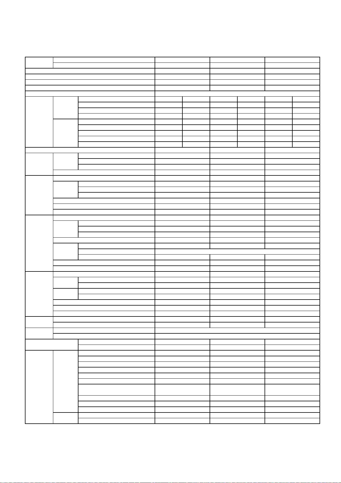
2. SPECIFICATIONS
2-1. Specifications
Unit model Indoor
Outdoor
Cooling capacity (kW)
Cooling capacity range (kW)
Heating capacity (kW)
Heating capacity range (kW)
Power supply
Electric Indoor Operation mode Cooling Heating Cooling Heating Cooling Heating
characteristic Running current (A) 0.24-0.22 0.28-0.26 0.24-0.22 0.28-0.26 0.24-0.22 0.28-0.26
Power consumption (W) 25 30 25 30 25 30
Power factor (%) 47 48 47 48 47 48
Outdoor Operation mode Cooling Heating Cooling Heating Cooling Heating
Running current (A) 2.58-2.36 3.10-2.84 4.03-3.70 3.84-3.52 6.24
Power consumption (W) 485 580 820 800 1300 1370
Power factor (%) 78 78 87 88 91 93
Starting current (A)
COP
Operating Indoor High (Cooling/Heating) (dB-A)
noise Medium (Cooling/Heating) (dB-A)
Low (Cooling/Heating) (dB-A)
Outdoor (Cooling/Heating) (dB-A)
Indoor unit Unit model
Dimension Height (mm)
Width (mm)
Depth (mm)
Net weight (kg)
Fan motor output (W)
Air flow rate (Cooling/Heating) (m3/min)
Outdoor unit Unit model
Dimension Height (mm)
Width (mm)
Depth (mm)
Net weight (kg)
Compressor Motor output (W)
Type
Model
Fan motor output (W)
Air flow rate (Cooling/Heating) (m3/min)
Piping Type
connection Indoor unit Liquid side (mm)
Gas side (mm)
Outdoor unit Liquid side (mm)
Gas side (mm)
Maximum length (m)
Maximum chargeless length (m)
Maximum height difference (m)
Refrigerant Name of refrigerant
Weight (kg)
Wiring Power supply
connection Interconnection
Usable temperature range Indoor (Cooling/Heating) (°C)
Outdoor (Cooling/Heating) (°C)
Accessory Indoor unit Installation plate
Wireless remote controller
Batteries
Remote controller holder
Toshiba IAQ-Filter
Mounting screw
Remote controller holder
Pan head wood screw
Plasma ionizer purifier
Installation manual
Owner's manual
Outdoor unit Drain nipple
Water-proof rubber cap
RAS-10G2KVP-E
RAS-10G2AVP-E
2.50
0.55-3.50
3.20
0.45-5.80
2.82-2.58 3.3
5.15/5.52
42/43
33/33
24/24
46/47
RAS-10G2KVP-E
293
831
270
14
30
10.8-11.3
RAS-10G2AVP-E
630
800
300
42
750
DA111A1F-24F
43
31.2/31.2
Flare connection
∅6.35
9.52
∅
∅6.35
∅9.52
25
15
10
R410A
1.05
21-32/ 0-28
-10-46/-15-24
1
1
2
1
1
6(∅4x25L) 6(∅4x25L) 6(∅4x25L)
2(∅3.1x16L)
1
1
1
1
2
1 Ph, 220-240V, 50Hz & 1 Ph, 220V, 60Hz
8-3.10
Twin rotary type with DC-inverter variablespeed control
RAS-13G2KVP-E
RAS-13G2AVP-E
3.50
0.63-4.10
4.00
0.65-6.30
4.27-3.92 4.12
4.27/5.00
RAS-13G2KVP-E
11.2-12.1
RAS-13G2AVP-E
DA150A1T-21F
36.0/36.0
Flare connection
∅6.35
∅9.52
∅6.35
∅9.52
R410A
3Wires:includes earth (Outdoor)
4Wires:includes earth
21-32/ 0-28
-10-46/-15-24
2(∅3.1x16L)
-3.78
43/44
34/34
25/25
48/49
293
831
270
14
30
630
800
300
42
750
43
25
15
10
1.05
1
1
2
1
1
1
1
1
1
2
6.48-5.94 6.69-6.13
RAS-16G2KVP-E
RAS-16G2AVP-E
4.50
0.63-5.00
5.50
0.65-6.80
-5.72 6.41-5.87
3.46/4.01
44/45
35/35
26/26
49/50
RAS-16G2KVP-E
293
831
270
14
30
11.6-12.4
RAS-16G2AVP-E
630
800
300
42
750
DA150A1T-21F
43
42.4/42.4
Flare connection
∅6.35
∅12.7
∅6.35
∅12.7
25
15
10
R410A
1.05
21-32/ 0-28
-10-46/-15-24
1
1
2
1
1
2(∅3.1x16L)
1
1
1
1
2
– 5 –
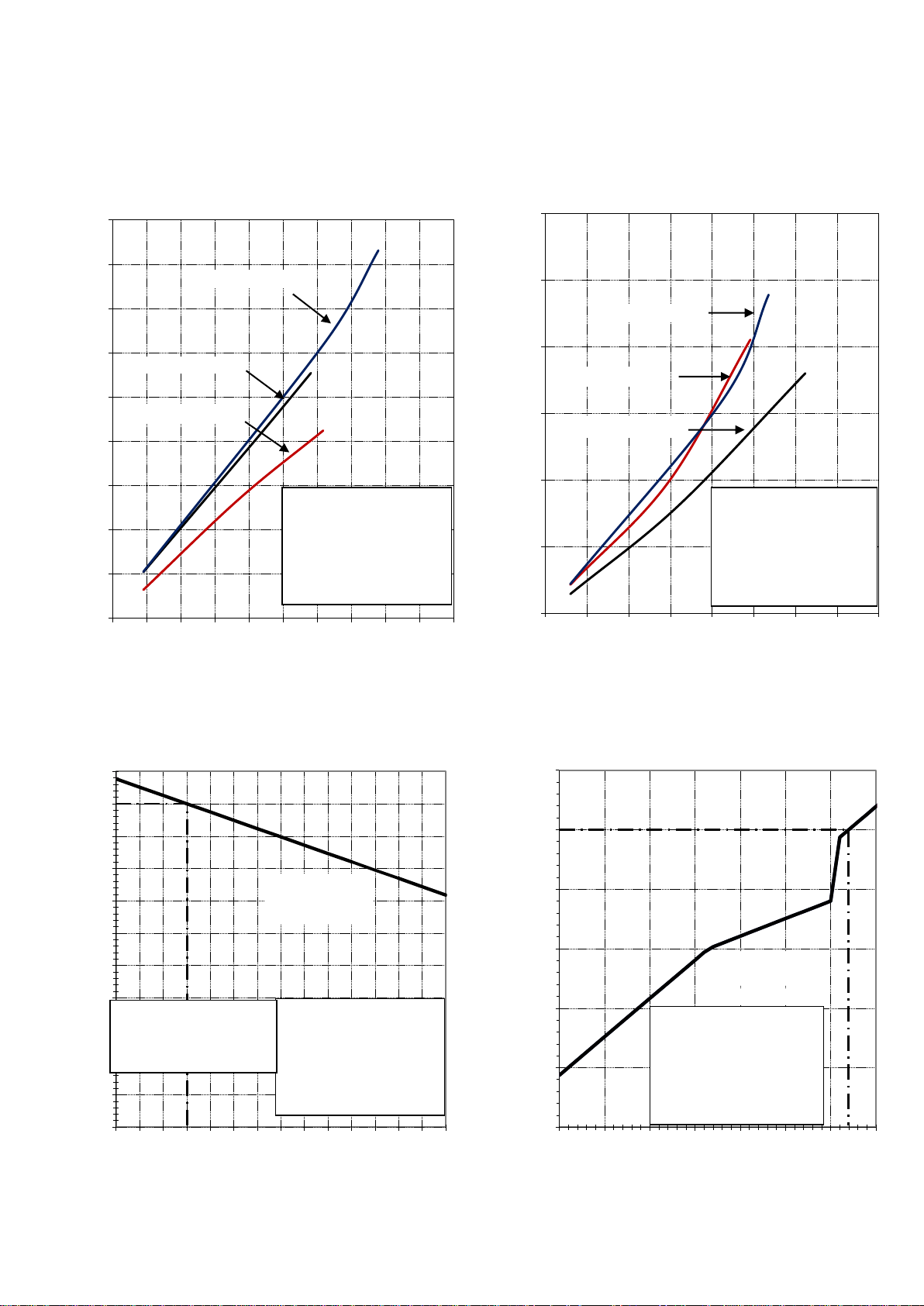
2-2. Operation Characteristic Curve
<Cooling> <Heating>
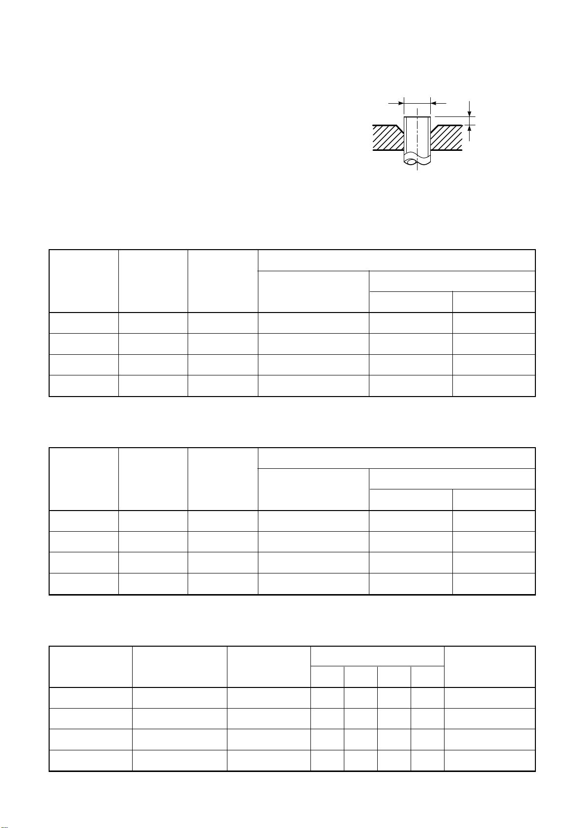
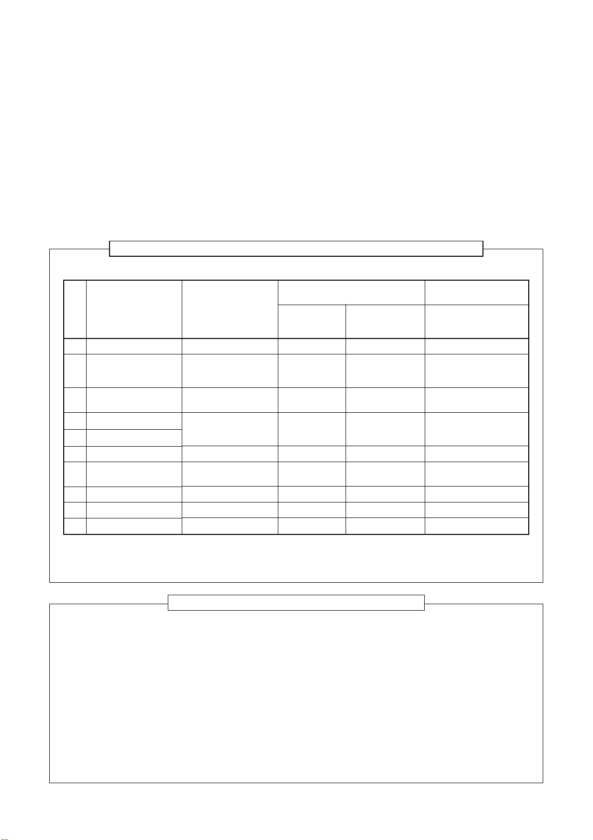
2-3. Capacity Variation ratio According to Temperature.
<Cooling> <Heating>
0
1
2
3
4
5
6
7
8
9
0 10 20 30 40 50 60 70 80 90 100
Current (A)
Compressor Speed (RPS)
0
2
4
6
8
10
12
0 15 30 45 60 75 90 105 120
Current (A)
Compressor Speed (RPS)
RAS-16G2KVP-E
RAS-13G2KVP-E
Conditions
Indoor : DB 27oC/WB 19oC
Outdoor : DB 35oC/WB 24oC
Indoor Air Flow : High
Pipe Length : 5m
Voltage : 230V
Conditions
Indoor : DB 20oC/WB 15oC
Outdoor : DB 7oC/WB 6oC
Indoor Air Flow : High
Pipe Length : 5m
Voltage : 230V
RAS-10G2KVP-E
0.0
20.0
40.0
60.0
80.0
100.0
120.0
-25 -20 -15 -10 -5 0 5 10
Heating Capacity ratio (%)
Outside Temperature ( ºC)
RAS-10G2KVP-E
RAS-13G2KVP-E
RAS-16G2KVP-E
RAS-10G2KVP-E
RAS-13G2KVP-E
50.0
55.0
60.0
65.0
70.0
75.0
80.0
85.0
90.0
95.0
100.0
105.0
32 33 34 35 36 37 38 39 40 41 42 43 44 45 46
Cooling Capacity ratio (%)
Outside Temperature ( oC)
Conditions
Indoor : DB 27oC/WB 19oC
Outdoor : DB 35oC/WB 24oC
Indoor Air Flow : High
Pipe Length : 5m
Voltage : 230V
Capacity ratio : 100 %=
2.50kW(RAS-10G2KVP-E)
3.50kW(RAS-13G2KVP-E)
4.50kW(RAS-16G2KVP-E)
RAS-16G2KVP-E
RAS-13G2KVP-E
Conditions
Indoor : DB 20oC/WB 15oC
Outdoor : DB 7oC/WB 6oC
Indoor Air Flow : High
Pipe Length : 5m
Voltage : 230V
RAS-10G2KVP-E
RAS-16G2KVP-E
FILE NO. SVM-14017
– 6 –

3. REFRIGERANT R410A
FILE NO. SVM-14017
This air conditioner adopts the new refrigerant HFC
(R410A) which does not damage the ozone layer.
The working pressure of the new refrigerant R410A
is 1.6 times higher than conventional refrigerant
(R22). The refrigerating oil is also changed in
accordance with change of refrigerant, so be careful
that water, dust, and existing refrigerant or refrigerating oil are not entered in the refrigerant cycle of the
air conditioner using the new refrigerant during
installation work or servicing time.
The next section describes the precautions for air
conditioner using the new refrigerant. Conforming to
contents of the next section together with the
general cautions included in this manual, perform
the correct and safe work.
3-1. Safety During Installation/Servicing
As R410A’s pressure is about 1.6 times higher than
that of R22, improper installation/servicing may
cause a serious trouble. By using tools and materials exclusive for R410A, it is necessary to carry out
installation/servicing safely while taking the following
precautions into consideration.
1. Never use refrigerant other than R410A in an air
conditioner which is designed to operate with
R410A.
If other refrigerant than R410A is mixed, pressure
in the refrigeration cycle becomes abnormally
high, and it may cause personal injury, etc. by a
rupture.
2. Confirm the used refrigerant name, and use tools
and materials exclusive for the refrigerant R410A.
The refrigerant name R410A is indicated on the
visible place of the outdoor unit of the air conditioner using R410A as refrigerant. To prevent
mischarging, the diameter of the service port
differs from that of R22.
3. If a refrigeration gas leakage occurs during
installation/servicing, be sure to ventilate fully.
If the refrigerant gas comes into contact with fire,
a poisonous gas may occur.
4. When installing or removing an air conditioner, do
not allow air or moisture to remain in the refrigeration cycle. Otherwise, pressure in the refrigeration cycle may become abnormally high so
that a rupture or personal injury may be caused.
5. After completion of installation work, check to
make sure that there is no refrigeration gas
leakage.
If the refrigerant gas leaks into the room, coming
into contact with fire in the fan-driven heater,
space heater, etc., a poisonous gas may occur.
6. When an air conditioning system charged with a
large volume of refrigerant is installed in a small
room, it is necessary to exercise care so that,
even when refrigerant leaks, its concentration
does not exceed the marginal level.
If the refrigerant gas leakage occurs and its
concentration exceeds the marginal level, an
oxygen starvation accident may result.
7. Be sure to carry out installation or removal
according to the installation manual.
Improper installation may cause refrigeration
trouble, water leakage, electric shock, fire, etc.
8. Unauthorized modifications to the air conditioner
may be dangerous. If a breakdown occurs
please call a qualified air conditioner technician
or electrician.
Improper repair’s may result in water leakage,
electric shock and fire, etc.
3-2. Refrigerant Piping Installation
3-2-1. Piping Materials and Joints Used
For the refrigerant piping installation, copper pipes
and joints are mainly used. Copper pipes and joints
suitable for the refrigerant must be chosen and
installed. Furthermore, it is necessary to use clean
copper pipes and joints whose interior surfaces are
less affected by contaminants.
1. Copper Pipes
It is necessary to use seamless copper pipes
which are made of either copper or copper alloy
and it is desirable that the amount of residual oil
is less than 40 mg/10 m. Do not use copper
pipes having a collapsed, deformed or discolored
portion (especially on the interior surface).
Otherwise, the expansion valve or capillary tube
may become blocked with contaminants.
As an air conditioner using R410A incurs pressure higher than when using R22, it is necessary
to choose adequate materials.
Thicknesses of copper pipes used with R410A
are as shown in Table 3-2-1. Never use copper
pipes thinner than 0.8 mm even when it is
available on the market.
– 7 –
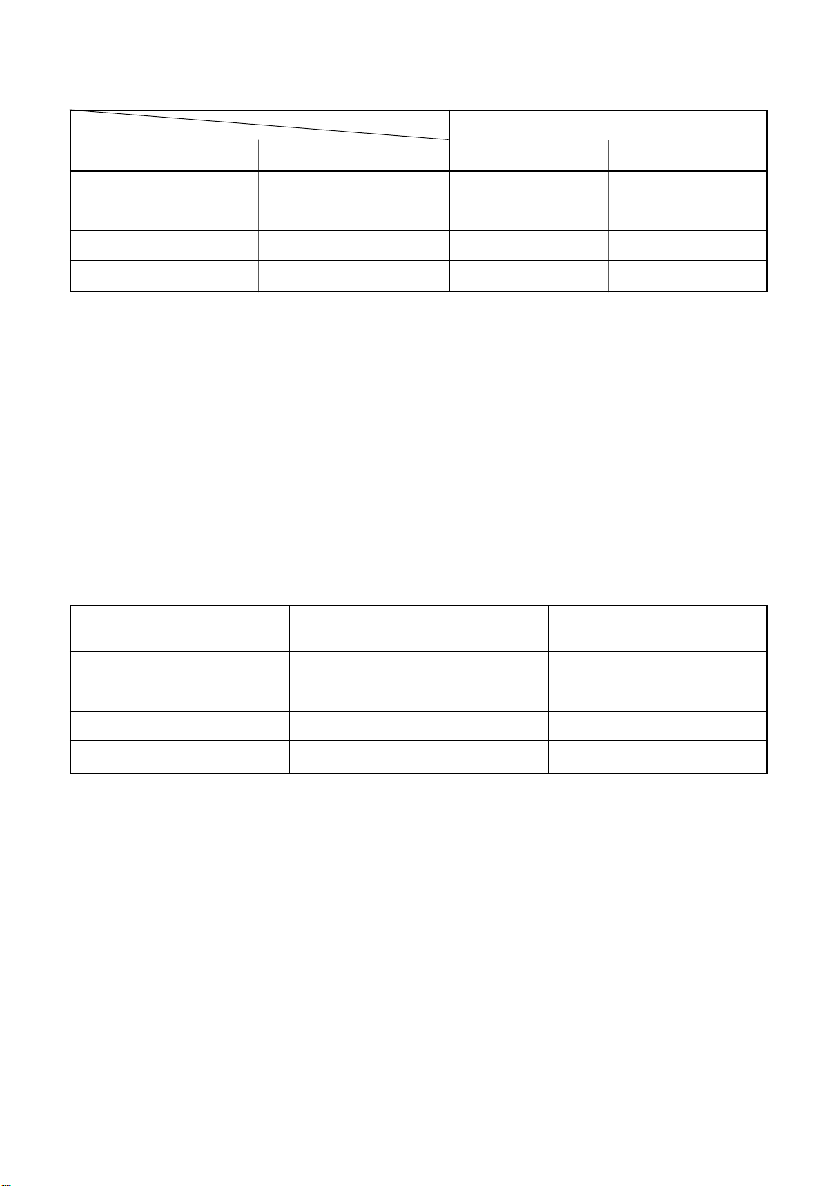
Table 3-2-1 Thicknesses of annealed copper pipes
Thickness (mm)
FILE NO. SVM-14017
Nominal diameter
1/4
3/8
1/2
5/8
Outer diameter (mm)
6.35
9.52
12.70
15.88
R410A R22
0.80 0.80
0.80 0.80
0.80 0.80
1.00 1.00
2. Joints
For copper pipes, flare joints or socket joints are used. Prior to use, be sure to remove all contaminants.
a) Flare Joints
Flare joints used to connect the copper pipes cannot be used for pipings whose outer diameter exceeds
20 mm. In such a case, socket joints can be used.
Sizes of flare pipe ends, flare joint ends and flare nuts are as shown in Tables 3-2-3 to 3-2-6 below.
b) Socket Joints
Socket joints are such that they are brazed for connections, and used mainly for thick pipings whose
diameter is larger than 20 mm.
Thicknesses of socket joints are as shown in Table 3-2-2.
Table 3-2-2 Minimum thicknesses of socket joints
Nominal diameter
1/4
3/8
1/2
5/8
Reference outer diameter of
copper pipe jointed (mm)
6.35
9.52
12.70
15.88
Minimum joint thickness
(mm)
0.50
0.60
0.70
0.80
3-2-2. Processing of Piping Materials
When performing the refrigerant piping installation, care should be taken to ensure that water or dust does not
enter the pipe interior, that no other oil than lubricating oils used in the installed air-water heat pump is used,
and that refrigerant does not leak. When using lubricating oils in the piping processing, use such lubricating oils
whose water content has been removed. When stored, be sure to seal the container with an airtight cap or any
other cover.
1. Flare processing procedures and precautions
a) Cutting the Pipe
By means of a pipe cutter, slowly cut the pipe so that it is not deformed.
b) Removing Burrs and Chips
If the flared section has chips or burrs, refrigerant leakage may occur.
Carefully remove all burrs and clean the cut surface before installation.
c) Insertion of Flare Nut
– 8 –
d) Flare Processing
Make certain that a clamp bar and copper
pipe have been cleaned.
By means of the clamp bar, perform the flare
processing correctly.
Use either a flare tool for R410A or conventional flare tool.
Flare processing dimensions differ according
to the type of flare tool. When using a conventional flare tool, be sure to secure “dimension A” by using a gauge for size adjustment.
Table 3-2-3 Dimensions related to flare processing for R410A
Nominal
diameter
Outer
diameter
(mm)
Thickness
(mm)
Fig. 3-2-1 Flare processing dimensions
Flare tool for R410A
clutch type
FILE NO. SVM-14017
ØD
A
A (mm)
Conventional flare tool
Clutch type Wing nut type
1/4
3/8
1/2
5/8
Nominal
diameter
1/4
3/8
1/2
5/8
6.35
9.52
12.70
15.88
Table 3-2-4 Dimensions related to flare processing for R22
Outer
diameter
(mm)
6.35
9.52
12.70
15.88
0.8
0.8
0.8
1.0
Thickness
(mm)
0.8
0.8
0.8
1.0
0 to 0.5
0 to 0.5
0 to 0.5
0 to 0.5
Flare tool for R22
clutch type
0 to 0.5
0 to 0.5
0 to 0.5
0 to 0.5
1.0 to 1.5 1.5 to 2.0
1.0 to 1.5 1.5 to 2.0
1.0 to 1.5 2.0 to 2.5
1.0 to 1.5 2.0 to 2.5
A (mm)
Conventional flare tool
Clutch type Wing nut type
0.5 to 1.0 1.0 to 1.5
0.5 to 1.0 1.0 to 1.5
0.5 to 1.0 1.5 to 2.0
0.5 to 1.0 1.5 to 2.0
Nominal
diameter
1/4
3/8
1/2
5/8
Table 3-2-5 Flare and flare nut dimensions for R410A
Outer diameter
(mm)
6.35
9.52
12.70
15.88
Thickness
(mm)
0.8
0.8
0.8
1.0
Dimension (mm)
ABCD
9.1 9.2 6.5 13
13.2 13.5 9.7 20
16.6 16.0 12.9 23
19.7 19.0 16.0 25
– 9 –
Flare nut width
(mm)
17
22
26
29

Table 3-2-6 Flare and flare nut dimensions for R22
FILE NO. SVM-14017
Nominal
diameter
1/4
3/8
1/2
5/8
3/4
Outer diameter
(mm)
6.35
9.52
12.70
15.88
19.05
45° to 46°
Thickness
(mm)
0.8
0.8
0.8
1.0
1.0
B A
Dimension (mm)
ABCD
9.0 9.2 6.5 13
13.0 13.5 9.7 20
16.2 16.0 12.9 20
19.7 19.0 16.0 23
23.3 24.0 19.2 34
D
C
43° to 45°
Flare nut width
(mm)
17
22
24
27
36
Fig. 3-2-2 Relations between flare nut and flare seal surface
2. Flare Connecting Procedures and Precautions
a) Make sure that the flare and union portions do not have any scar or dust, etc.
b) Correctly align the processed flare surface with the union axis.
c) Tighten the flare with designated torque by means of a torque wrench. The tightening torque for R410A is
the same as that for conventional R22. Incidentally, when the torque is weak, the gas leakage may occur.
When it is strong, the flare nut may crack and may be made non-removable. When choosing the tightening torque, comply with values designated by manufacturers. Table 3-2-7 shows reference values.
NOTE :
When applying oil to the flare surface, be sure to use oil designated by the manufacturer.
If any other oil is used, the lubricating oils may deteriorate and cause the compressor to burn out.
Table 3-2-7 Tightening torque of flare for R410A [Reference values]
Nominal
diameter
Outer diameter
(mm)
Tightening torque
N•m (kgf•cm)
Tightening torque of torque
wrenches available on the market
N•m (kgf•cm)
1/4
3/8
1/2
5/8
6.35
9.52
12.70
15.88
14 to 18 (140 to 180)
33 to 42 (330 to 420)
50 to 62 (500 to 620)
63 to 77 (630 to 770)
– 10 –
16 (160), 18 (180)
42 (420)
55 (550)
65 (650)
FILE NO. SVM-14017
3-3. Tools
3-3-1. Required Tools
The service port diameter of packed valve of the outdoor unit in the air-water heat pump using R410A is
changed to prevent mixing of other refrigerant. To reinforce the pressure-resisting strength, flare processing
dimensions and opposite side dimension of flare nut (For Ø12.7 copper pipe) of the refrigerant piping are
lengthened.
The used refrigerating oil is changed, and mixing of oil may cause a trouble such as generation of sludge,
clogging of capillary, etc. Accordingly, the tools to be used are classified into the following three types.
1. Tools exclusive for R410A (Those which cannot be used for conventional refrigerant (R22))
2. Tools exclusive for R410A, but can be also used for conventional refrigerant (R22)
3. Tools commonly used for R410A and for conventional refrigerant (R22)
The table below shows the tools exclusive for R410A and their interchangeability.
Tools exclusive for R410A (The following tools for R410A are required.)
Tools whose specifications are changed for R410A and their interchangeability
air-water heat pump installation
No.
1
2
3
4
5
6
7
8
9
10
(Note 1) When flaring is carried out for R410A using the conventional flare tools, adjustment of projection
(Note 2) Charging cylinder for R410A is being currently developed.
Used tool
Flare tool
Copper pipe gauge for
adjusting projection
margin
Torque wrench
(For Ø12.7)
Gauge manifold
Charge hose
Vacuum pump adapter
Electronic balance for
refrigerant charging
Refrigerant cylinder
Leakage detector
Charging cylinder
margin is necessary. For this adjustment, a copper pipe gauge, etc. are necessary.
Pipe flaring
Flaring by
conventional flare tool
Connection of flare nut
Evacuating, refrigerant
charge, run check, etc.
Vacuum evacuating
Refrigerant charge
Refrigerant charge
Gas leakage check
Refrigerant charge
Usage
Existence of
new equipment
for R410A
Ye s
Ye s
Ye s
Ye s
Ye s
Ye s
Ye s
Ye s
(Note 2)
R410A
Whether conventional equipment
can be used
*(Note 1)
*(Note 1)
×
×
×
×
×
×
×
Conventional air-water
heat pump installation
Whether new equipment
can be used with
conventional refrigerant
¡
*(Note 1)
×
×
¡
¡
×
¡
×
General tools (Conventional tools can be used.)
In addition to the above exclusive tools, the following equipments which serve also for R22 are necessary
as the general tools.
1. Vacuum pump
Use vacuum pump by attaching
vacuum pump adapter.
2. Torque wrench (For Ø6.35, Ø9.52)
3. Pipe cutter
4. Reamer
5. Pipe bender
6. Level vial
7. Screwdriver (+, –)
8. Spanner or Monkey wrench
9. Hole core drill (Ø65)
10. Hexagon wrench
(Opposite side 4mm)
11. Tape measure
12. Metal saw
Also prepare the following equipments for other installation method and run check.
1. Clamp meter
2. Thermometer
3. Insulation resistance tester
4. Electroscope
– 11 –
FILE NO. SVM-14017
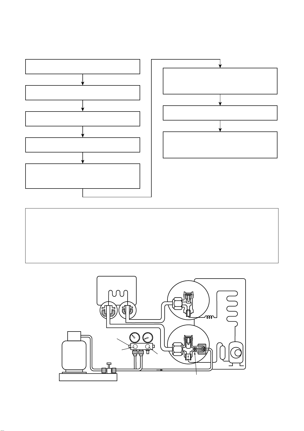
3-4. Recharging of Refrigerant
When it is necessary to recharge refrigerant, charge the specified amount of new refrigerant according to the
following steps.
Recover the refrigerant, and check no refrigerant
remains in the equipment.
Connect the charge hose to packed valve service
port at the outdoor unit’s gas side.
Connect the charge hose to the vacuum pump
adapter.
Open fully both packed valves at liquid and gas
sides.
When the compound gauge’s pointer has indicated
–0.1 Mpa (–76 cmHg), place the handle Low in the
fully closed position, and turn off the vacuum pump’s
power switch.
Keep the status as it is for 1 to 2 minutes, and ensure
that the compound gauge’s pointer does not return.
Set the refrigerant cylinder to the electronic balance,
connect the connecting hose to the cylinder and the
connecting port of the electronic balance, and charge
liquid refrigerant.
Place the handle of the gauge manifold Low in the
fully opened position, and turn on the vacuum pump’s
power switch. Then, evacuating the refrigerant in the
cycle.
(For refrigerant charging, see the figure below.)
1. Never charge refrigerant exceeding the specified amount.
2. If the specified amount of refrigerant cannot be charged, charge refrigerant bit by bit in COOL mode.
3. Do not carry out additional charging.
When additional charging is carried out if refrigerant leaks, the refrigerant composition changes in the
refrigeration cycle, that is characteristics of the air conditioner changes, refrigerant exceeding the
specified amount is charged, and working pressure in the refrigeration cycle becomes abnormally high
pressure, and may cause a rupture or personal injury.
(Indoor unit)
Opened
(Outdoor unit)
Refrigerant cylinder
(with siphon)
Check valve
Opened
Open/close
valve for charging
Electronic balance for refrigerant charging
Fig. 3-4-1 Configuration of refrigerant charging
Opened
Closed
Service port
– 12 –
FILE NO. SVM-14017
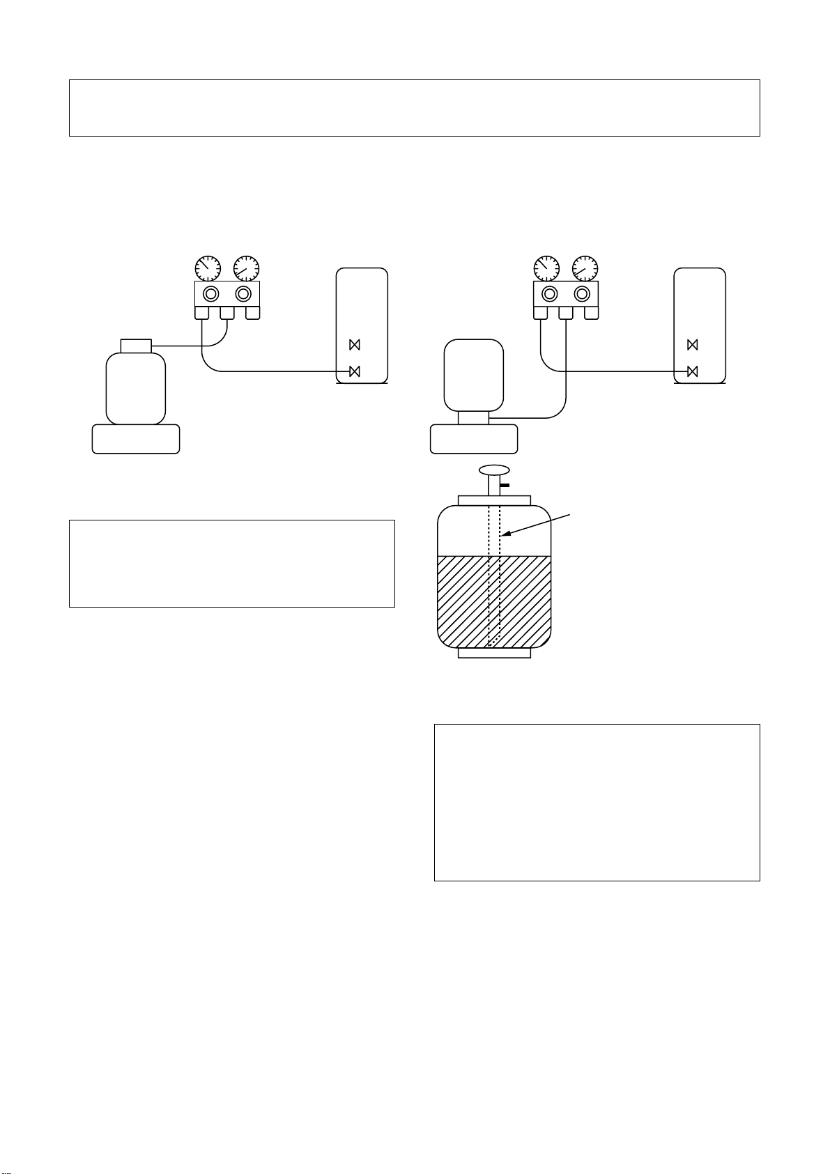
1. Be sure to make setting so that liquid can be charged.
2. When using a cylinder equipped with a siphon, liquid can be charged without turning it upside down.
It is necessary for charging refrigerant under condition of liquid because R410A is mixed type of refrigerant.
Accordingly, when charging refrigerant from the refrigerant cylinder to the equipment, charge it turning the
cylinder upside down if cylinder is not equipped with siphon.
[ Cylinder with siphon ] [ Cylinder without siphon ]
Gauge manifold
OUTDOOR unit
Refrigerant
cylinder
Gauge manifold
OUTDOOR unit
cylinder
Refrigerant
Electronic
balance
R410A refrigerant is HFC mixed refrigerant.
Therefore, if it is charged with gas, the composition of the charged refrigerant changes and the
characteristics of the equipment varies.
3-5. Brazing of Pipes
3-5-1. Materials for Brazing
1. Silver brazing filler
Silver brazing filler is an alloy mainly composed
of silver and copper. It is used to join iron, copper
or copper alloy, and is relatively expensive though
it excels in solderability.
2. Phosphor bronze brazing filler
Phosphor bronze brazing filler is generally used
to join copper or copper alloy.
Electronic
balance
Siphon
Fig. 3-4-2
1. Phosphor bronze brazing filler tends to react
with sulfur and produce a fragile compound
water solution, which may cause a gas
leakage. Therefore, use any other type of
brazing filler at a hot spring resort, etc., and
coat the surface with a paint.
2. When performing brazing again at time of
servicing, use the same type of brazing filler.
3-5-2. Flux
3. Low temperature brazing filler
Low temperature brazing filler is generally called
solder, and is an alloy of tin and lead. Since it is
weak in adhesive strength, do not use it for
refrigerant pipes.
1. Reason why flux is necessary
• By removing the oxide film and any foreign
matter on the metal surface, it assists the flow
of brazing filler.
• In the brazing process, it prevents the metal
surface from being oxidized.
• By reducing the brazing filler’s surface tension,
the brazing filler adheres better to the treated
metal.
– 13 –
2. Characteristics required for flux
• Activated temperature of flux coincides with the
brazing temperature.
• Due to a wide effective temperature range, flux
is hard to carbonize.
• It is easy to remove slag after brazing.
• The corrosive action to the treated metal and
brazing filler is minimum.
• It excels in coating performance and is harmless to the human body.
As the flux works in a complicated manner as
described above, it is necessary to select an
adequate type of flux according to the type and
shape of treated metal, type of brazing filler and
brazing method, etc.
3. Types of flux
• Noncorrosive flux
Generally, it is a compound of borax and boric
acid.
It is effective in case where the brazing temperature is higher than 800°C.
• Activated flux
Most of fluxes generally used for silver brazing
are this type.
It features an increased oxide film removing
capability due to the addition of compounds
such as potassium fluoride, potassium chloride
and sodium fluoride to the borax-boric acid
compound.
4. Piping materials for brazing and used
brazing filler/flux
FILE NO. SVM-14017
3-5-3. Brazing
As brazing work requires sophisticated techniques,
experiences based upon a theoretical knowledge, it
must be performed by a person qualified.
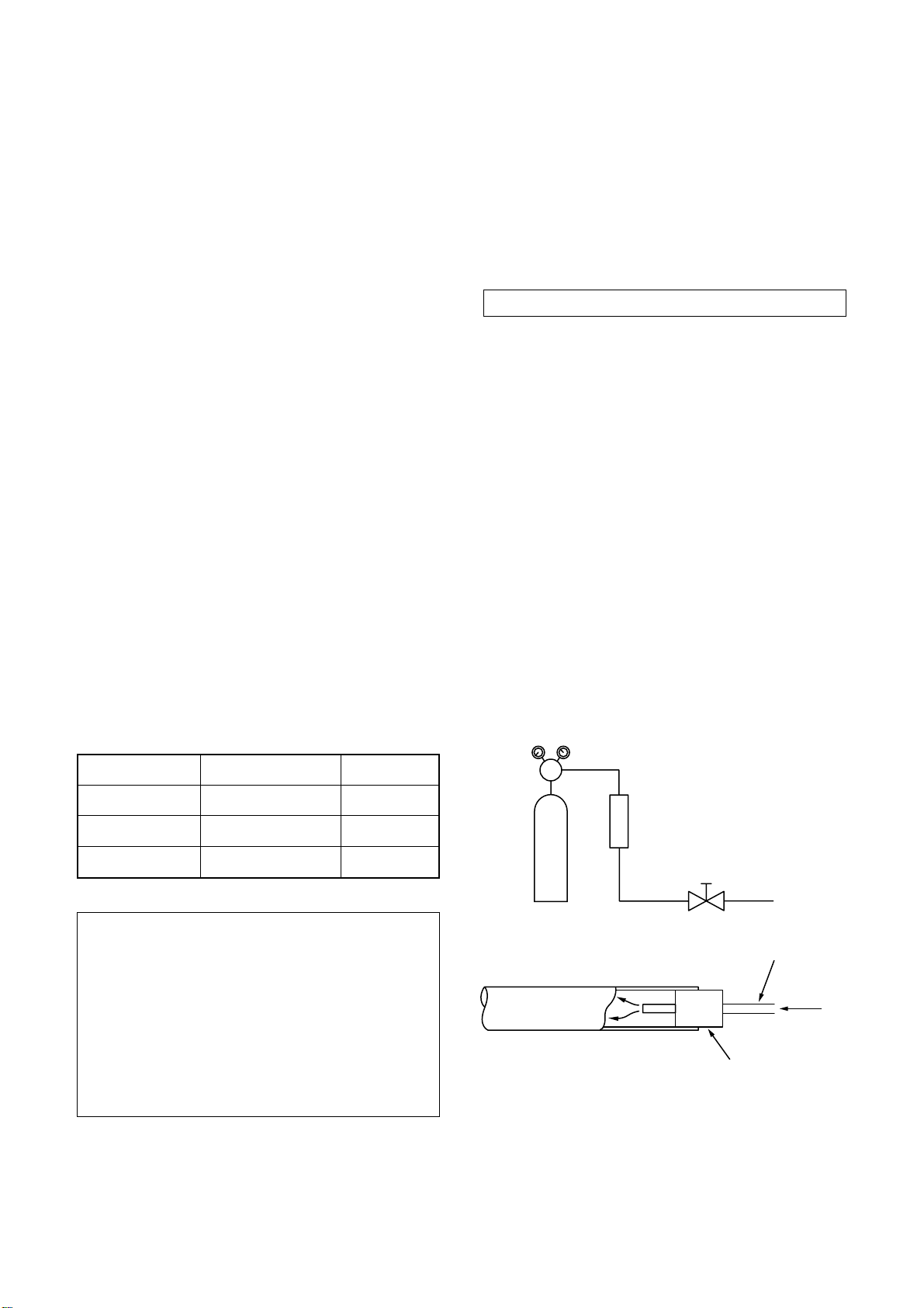
In order to prevent the oxide film from occurring in
the pipe interior during brazing, it is effective to
proceed with brazing while letting dry Nitrogen gas
(N2) flow.
Never use gas other than Nitrogen gas.
1. Brazing method to prevent oxidation
1) Attach a reducing valve and a flow-meter to
the Nitrogen gas cylinder.
2) Use a copper pipe to direct the piping material, and attach a flow-meter to the cylinder.
3) Apply a seal onto the clearance between the
piping material and inserted copper pipe for
Nitrogen in order to prevent backflow of the
Nitrogen gas.
4) When the Nitrogen gas is flowing, be sure to
keep the piping end open.
5) Adjust the flow rate of Nitrogen gas so that it
is lower than 0.05 m3/Hr or 0.02 MPa
(0.2kgf/cm2) by means of the reducing valve.
6) After performing the steps above, keep the
Nitrogen gas flowing until the pipe cools down
to a certain extent (temperature at which
pipes are touchable with hands).
7) Remove the flux completely after brazing.
Piping material
Copper - Copper
Copper - Iron
Iron - Iron
Used brazing filler
Phosphor copper
Silver
Silver
Used flux
Do not use
Paste flux
Vapor flux
1. Do not enter flux into the refrigeration cycle.
2. When chlorine contained in the flux remains
within the pipe, the lubricating oil deteriorates.
Therefore, use a flux which does not contain
chlorine.
3. When adding water to the flux, use water
which does not contain chlorine (e.g. distilled
water or ion-exchange water).
4. Remove the flux after brazing.
M
Flow meter
Stop valve
Nitrogen gas
cylinder
From Nitrogen cylinder
Pipe
Nitrogen
gas
Rubber plug
Fig. 3-5-1 Prevention of oxidation during brazing
– 14 –
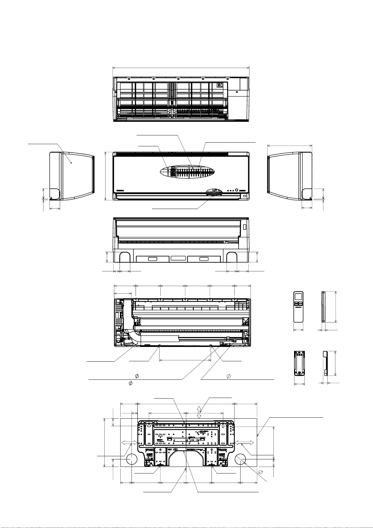
4-1. Indoor Unit
FILE NO. SVM-14017
4. CONSTRUCTION VIEWS
831
Front panel
64
62
6
Knock out system
Heat exchanger
Air filter
Plasma ion charger
(Air purifier)
293
Picoion generator
62
64 64
131.5 99
150 150 150 150
104.3
270
62
6 64
Knock out system
62
70.5 38
188
Drain hose
(0.6m)
Hanger
Connecting pipe(0.62m)
(For 10,13k : Flare 9.52mm)
(For 16k : Flare 12.7mm)
35
45
190mm
or more
293
Minimum distance
to wall
46
69
174
Center line
Hanger
156 156
312
Connecting pipe(0.66m)
Flare
Minimum distance
to wall 52mm
or more
590
225 225
HangerHanger
Installation plate outline
Hanger
6.35mm
137 104
225mm
or more
102 174
Outline of indoor unit
65
198
46
Minimum distance
to wall
57
20
Wiress remote controller
149
63
26
Remote controller holder
– 15 –
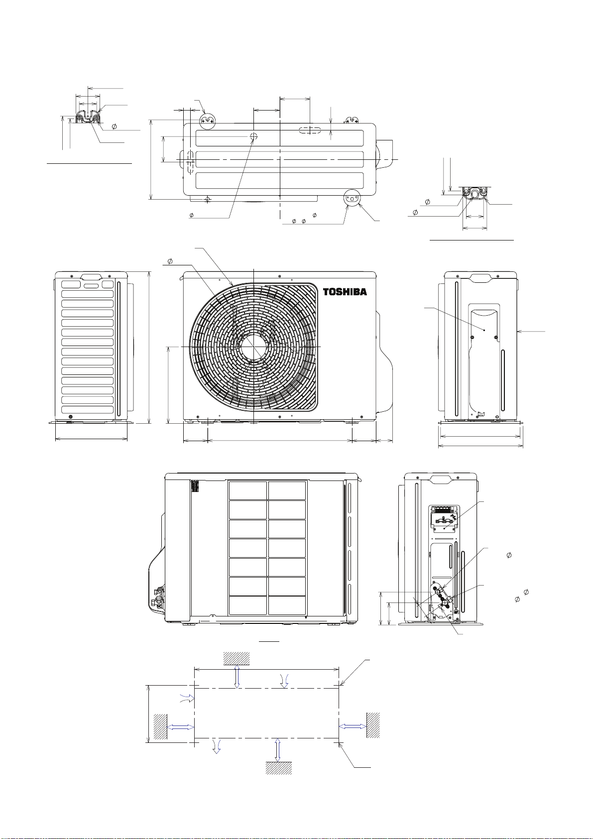
4-2. Outdoor Unit
600
50
36
R
15
6
hole
R
316
330
A detail drawing (Back leg)
5.5
106
330
FAN-GUARD
440
A
29
25 Drain outlet
108
(For
125
8-
29
2-
11x14 Hole
10 anchor bolt)
B
COVER-PV
FILE NO. SVM-14017
330
316
R
6
hole
11
x14 hole
B detail drawing (Front leg)
36
50
15
View Z
299
630
318
View Z
69100 600
99
137
92
54
330
351
Electrical part
Liquid side
(Flare
Gas side
(10,13 : Flare
(16 : Flare
Service port
6.35)
9.52)
12.70)
100 or more
320
100 or more
Air outlel
Installation dimension
600
– 16 −
Air intlel
600 or more
2 - R5-5 x 17L Ushape
(For ∅8 - ∅10 anchor bolt)
600 or more
2 - ∅11 x 14 Long holes (For ∅8- ∅10 anchor bolt)
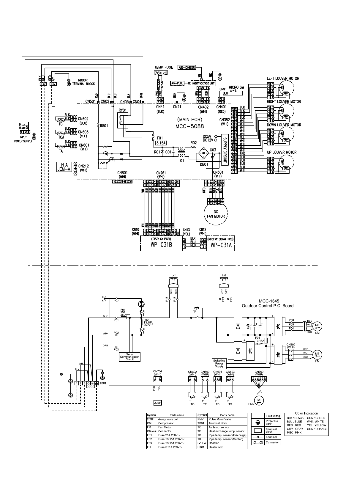
5. WIRING DIAGRAM
FILE NO. SVM-14017
– 17 –
6-1. Indoor Unit
FILE NO. SVM-14017
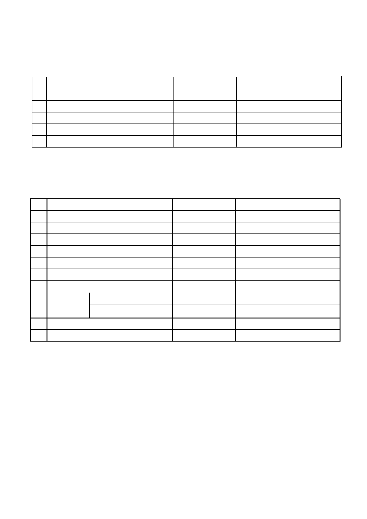
6. SPECIFICATIONS OF ELECTRICAL PARTS
No.
1
Fan motor (for indoor)
2 Room temp. sensor (TA-sensor)
3 Heat exchanger temp. sensor (TC-sensor)
Heat exchanger temp. sensor (Tcj-sensor)
4
5
Louver motor
Parts n ame
MF-340-30-3 DC250~370, 30W
( - )
( - )
( - )
24BYJ48-HT
10kΩ at 25°C
10kΩ at 25°C
10kΩ at 25°C
Output (Rated) 1W, 16 poles, DC12V
6-2. Outdoor Unit
No.
1 Reactor L = 10mH, 16A
2 Outdoor fan motor DC140V, 43W
3 Suction temp. sensor (TS sensor)
4 Discharge temp. sensor (TD sensor)
Parts name Model na me Rating
CH-57-Z-T ; R
ICF-140-43-4R
(Inverter attached)
(Inverter attached)
10k
62k
Ω(25°C)
Ω(20°C)
Specif icationsType
5 Outside air temp. sensor (TO sensor)
6 Heat exchanger temp. sensor (TE sensor)
7 Terminal block (6P) 20A, AC250V
10k
Compressor
8
9 Coil for PMV DC12V
10 Coil for 4-way valve
3-phases 4-poles 750W
13k, 16k
3-phases 4-poles 1100W
(Inverter attached)
(Inverter attached)
JX0-6B
DA111A1F-24F
DA150A1T-21F
CAM-MD12TCTH-5
STF-H01AZ1724A1
10k
Ω (25°C)
10k
Ω(25°C)
DC12V
– 18 −
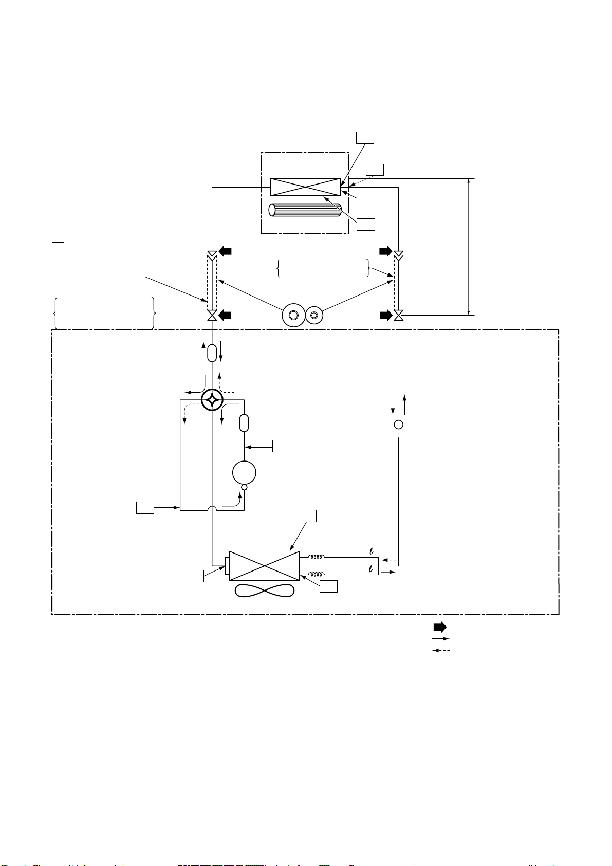
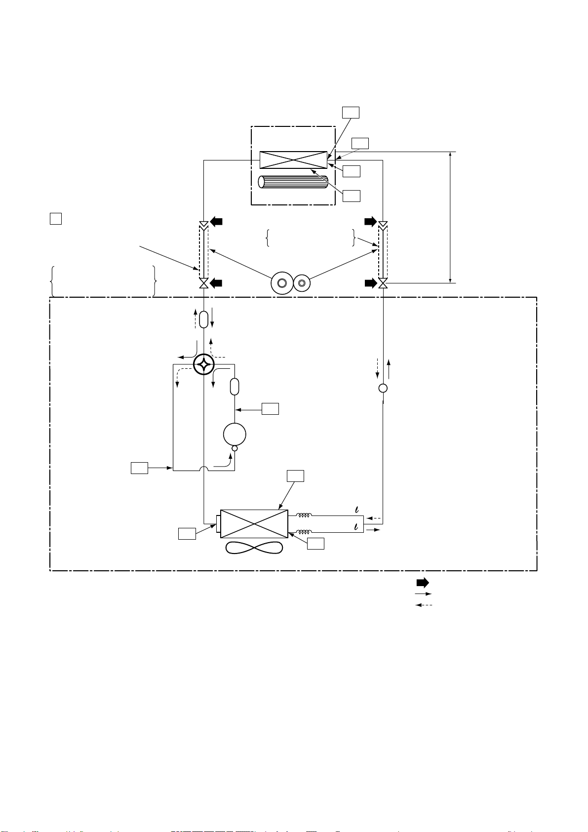
7. REFRIGERANT CYCLE DIAGRAM
7-1. Refrigerant Cycle Diagram
RAS-10G2KVP-E / RAS-10G2AVP-E
INDOOR UNIT
Indoor heat
exchanger
T1
Temp. measurement
Tcj
TC
FILE NO. SVM-14017
P
Pressure measurement
Gauge attaching port
Vacuum pump connecting port
Deoxidized copper pipe
Outer dia. : 9.52mm
Thickness : 0.8mm
4-way valve
TS
Muffler
Muffler
Compressor
DA111A1F-24F
Outdoor heat
exchanger
Cross flow fan
Deoxidized copper pipe
Outer dia. : 6.35mm
Thickness : 0.8mm
Sectional shape
of heat insulator
TD
TO
Split capillary
Ø1.2 x 80
TA
Allowable height
difference : 10m
Pulse Modulating
valve at liquid side
Max. : 25m
Min. : 2m
Chargeless : 15m
Charge : 20g/m
(16 to 25m)
Allowable pipe length
Temp. measurement
T2
Propeller fan
OUTDOOR UNIT
Ø1.2 x 80
TE
NOTE :
Refrigerant amount : 1.05kg
Gas leak check position
Refrigerant flow (Cooling)
Refrigerant flow (Heating)
NOTE :
• The maximum pipe length of this air conditioner is 25 m. When the pipe length exceeds 15m, the additional
charging of refrigerant, 20g per 1m for the part of pipe exceeded 15m is required. (Max. 200g)
– 19 –
RAS-13G2KVP-E / RAS-13G2AVP-E
RAS-16G2KVP-E / RAS-16G2AVP-E
INDOOR UNIT
Indoor heat
exchanger
T1
Temp. measurement
Tcj
TC
FILE NO. SVM-14017
P
Pressure measurement
Gauge attaching port
Vacuum pump connecting port
Deoxidized copper pipe
Outer dia. : 9.52mm(13)
Thickness : 0.8mm
: 12.7mm(16)
4-way valve
TS
Muffler
Muffler
Compressor
DA150A1T
Outdoor heat
exchanger
Cross flow fan
Deoxidized copper pipe
Outer dia. : 6.35mm
Thickness : 0.8mm
Sectional shape
of heat insulator
TD
-21F
TO
Split capillary
Ø1.2 x 80
TA
Allowable height
difference : 10m
Pulse Modulating
valve at liquid side
Max. : 25m
Min. : 2m
Chargeless : 15m
Charge : 20g/m
(16 to 25m)
Allowable pipe length
Temp. measurement
T2
Propeller fan
OUTDOOR UNIT
Ø1.2 x 80
TE
NOTE :
Refrigerant amount : 1.05kg
Gas leak check position
Refrigerant flow (Cooling)
Refrigerant flow (Heating)
NOTE :
• The maximum pipe length of this air conditioner is 25 m. When the pipe length exceeds 15m, the additional
charging of refrigerant, 20g per 1m for the part of pipe exceeded 15m is required. (Max. 200g)
– 20 −
FILE NO. SVM-14017
7-2. Operation Data
<Cooling>
Tempeature Model name Standard Heat exchanger Indoor Outdoor Compressor
condition(°C) RAS- pressure pipe temp. fan mode fan mode revolution
Indoor Outdoor P (MPa) T1 (°C) T2 (°C) (rps)
27/19 35/- 10G2KVP-E 1.0 to 1.2 13 to 15 40 to 42 High High 37
13G2KVP-E 0.9 to 1.1 12 to 14 41 to 43 High High 42
16G2KVP-E 0.8 to 1.0 11 to 13 42 to 44 High High 62
<Heating>
Tempeature Model name Standard Heat exchanger Indoor Outdoor Compressor
condition(°C) RAS- pressure pipe temp. fan mode fan mode revolution
Indoor Outdoor P (MPa) T1 (°C) T2 (°C) (rps)
20/- 7/6 10G2KVP-E 2.3 to 2.5 33 to 35 2 to 3 High High 48
13G2KVP-E 2.5 to 2.7 36 to 38 2 to 3 High High 44
16G2KVP-E 2.7 to 2.9 39 to 41 1 to 2 High High 64
NOTES :
1. Measure surface temperature of heat exchanger pipe around center of heat exchaner path U bent.
(Thermistor themometer)
2. Connecting piping condition : 5 m
– 21 –
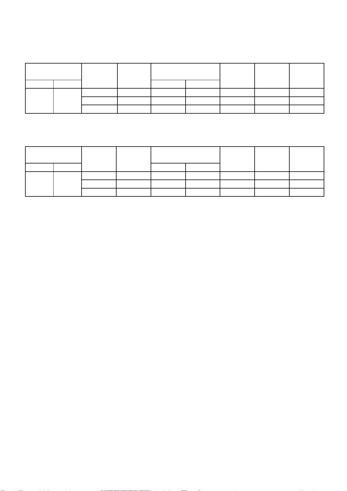
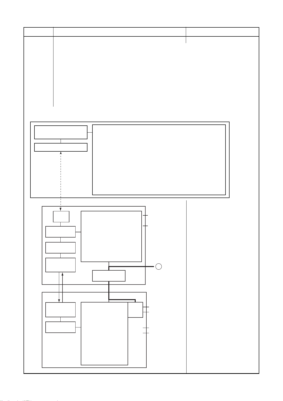
8-1. Indoor Unit
FILE NO. SVM-14017
8. CONTROL BLOCK DIAGRAM
Heat Exchanger Sensor (TCJ)
Heat Exchanger Sensor (TC)
Room Temperature Sensor (TA)
Infrared Rays Signal Receiver
and Indication
Initializing Circuit
Clock Frequency
Oscillator Circuit
Power Supply
Circuit
Converter
(D.C circuit)
Noise Filter
M.C.U.
Functions
Indoor Unit Control Unit
· Cold draft preventing Function
· 3-minute Delay at Restart for Compressor
· Fan Motor Starting Control
· Processing
(Temperature Processing)
· Timer / Weekly Timer
· Serial Signal Communication
· Clean Function
· Power Selection
Serial Signal Transmitter/Receiver
Louver Motor
Drive Control
Indoor Fan
Motor Control
Louver
Motor
Indoor
Indoor
Fan Motor
Air purifier
unit
Micro Switch
Power Supply
REMOTE CONTROLLER
Serial Signal Communication
(Operation Command and Information)
Remote Controller
Operation ( )
Operation Mode Selection
AUTO, COOL, DRY, HEAT
Thermo. Setting
Fan Speed Selection
ON TIMER Setting
OFF TIMER Setting
Louver AUTO Swing
Louver Direction Setting
ECO
Hi-POWER
COMFORT SLEEP
Infrared Rays, 36.7kHz
COMFORT SLEEPPOWER-SEL
PURE
WEEKLY ON / OFF
– 22 −
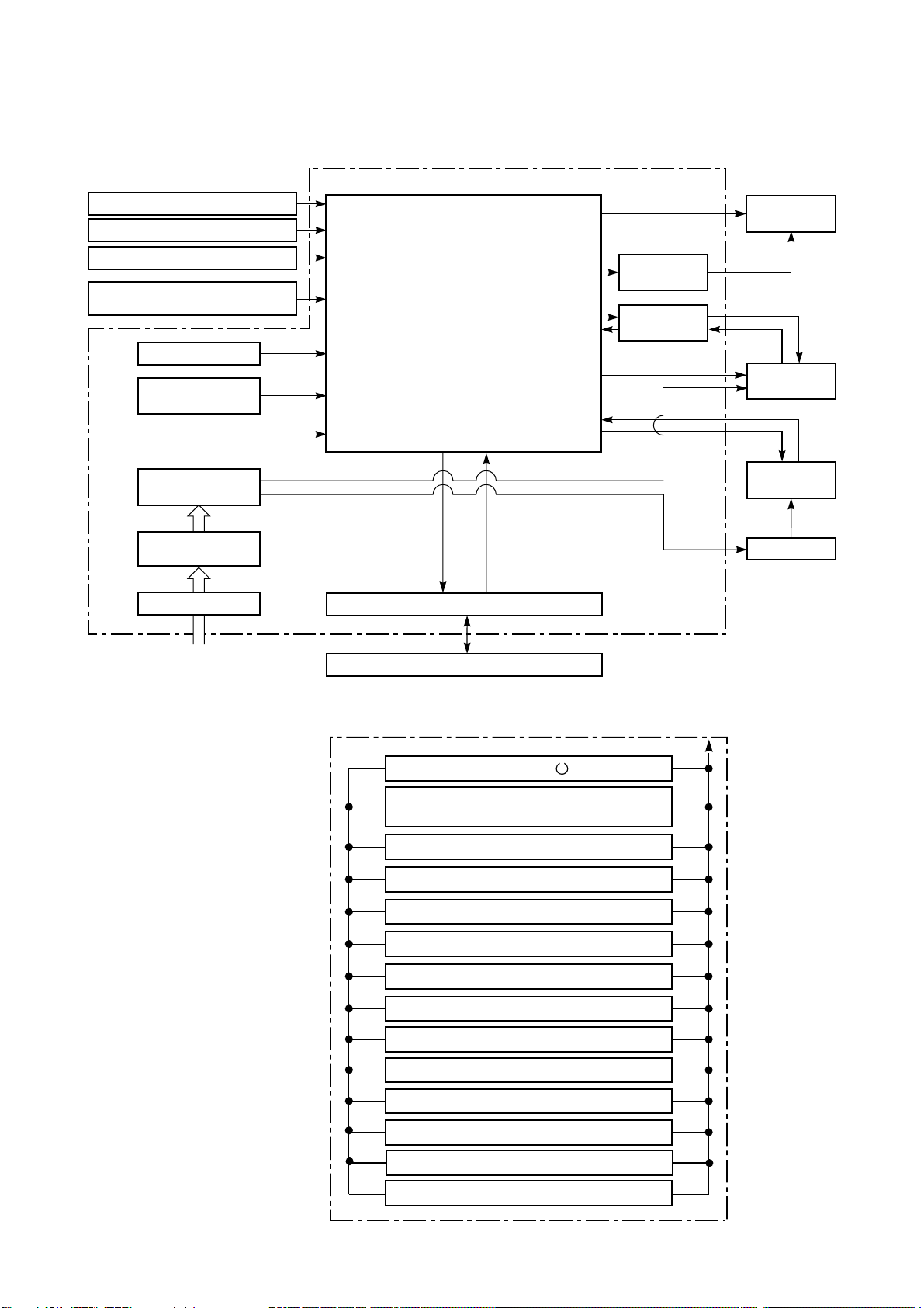
8-2. Outdoor Unit (Inverter Assembly)
detect
Current
circuit
Gate drive
detect
Current
FILE NO. SVM-14017
Compressor
Outdoor
Fan motor
Inverter
(DC → AC)
P.M.V. : Pulse Motor Valve
M.C.U. : Micro Control Unit
MICRO-COMPUTER BLOCK DIAGRAM
M.C.U
MCC-5088 (P.C.B) OUTDOOR UNIT
PWM synthesis function
Input current release control
IGBT over-current detect control
·
·······
circuit
Indoor unit
send/receive
circuit
Gate drive
Outdoor fan control
High power factor correction control
Inverter output frequency control
A/D converter function
P.M.V. control
Discharge temp. control
4-way valve control
Signal communication to indoor unit
···
Demand control function
·
4MHz
Clock
frequency
circuit
High Power
factor Correction
Converter
(AC → DC)
sensor
Input current
Filter
Noise
Inverter
(DC → AC)
Relay
circuit
of P.M.V.
Driver circuit
valve
4-way
P.M.V.
220–240 V ~50Hz
For INDOOR UNIT
Discharge
temp. sensor
Outdoor air
temp. sensor
Suction temp.
– 23 –
sensor
temp.sensor
Heat exchanger

9. OPERATION DESCRIPTION
FILE NO. SVM-14017
9-1. Outline of Air Conditioner Control
This air conditioner is a capacity-variable type air
conditioner, which uses AC or DC motor for the indoor
for motor and the outdoor fan motor. And the capacityproportional control compressor which can change the
motor speed in the range from 11 to 96 rps is
mounted. The DC motor drive circuit is mounted to the
indoor unit. The compressor and the inverter to control
fan motor are mounted to the outdoor unit.
The entire air conditioner is mainly controlled by the
indoor unit controller.
The indoor unit controller drives the indoor fan motor
based upon command sent from the remote controller,
and transfers the operation command to the outdoor
unit controller.
The outdoor unit controller receives operation command from the indoor unit side, and controls the
outdoor fan and the pulse Modulating valve. (P.M.V)
Besides, detecting revolution position of the compressor motor, the outdoor unit controller controls speed of
the compressor motor by controlling output voltage of
the inverter and switching timing of the supply power
(current transfer timing) so that motors drive according
to the operation command.
And then, the outdoor unit controller transfers reversely
the operating status information of the outdoor unit to
control the indoor unit controller.
As the compressor adopts four-pole brushless
DC motor, the frequency of the supply power
from inverter to compressor is two-times cycles
of the actual number of revolution.
1. Role of indoor unit controller
The indoor unit controller judges the operation
commands from the remote controller and assumes
the following functions.
• Judgment of suction air temperature of the indoor
heat exchanger by using the indoor temp. sensor.
(TA sensor)
• Judgment of the indoor heat exchanger temperature by using heat exchanger sensor (TC sensor)
(Prevent-freezing control, etc.)
• Louver motor control
• Indoor fan motor operation control
• LED (Light Emitting Diode) display control
• Transferring of operation command signal (Serial
signal) to the outdoor unit
• Reception of information of operation status
(Serial signal including outside temp. data) to the
outdoor unit and judgment/display of error
• Air purifier operation control
2. Role of outdoor unit controller
Receiving the operation command signal (Serial
signal) from the indoor unit controller, the outdoor
unit performs its role.
• Compressor operation control
• Operation control of outdoor fan motor
• P.M.V. control
• 4-way valve control
Operations followed to judgment
of serial signal from indoor side.
• Detection of inverter input current and current
release operation
• Over-current detection and prevention operation
to IGBT module (Compressor stop function)
• Compressor and outdoor fan stop function when
serial signal is off (when the serial signal does not
reach the board assembly of outdoor control by
trouble of the signal system)
• Transferring of operation information (Serial
signal) from outdoor unit controller to indoor unit
controller
• Detection of outdoor temperature and operation
revolution control
• Defrost control in heating operation (Temp.
measurement by outdoor heat exchanger and
control for 4-way valve and outdoor fan)
3. Contents of operation command signal
(Serial signal) from indoor unit controller to
outdoor unit controller
The following three types of signals are sent from
the indoor unit controller.
• Operation mode set on the remote controller
• Compressor revolution command signal defined
by indoor temperature and set temperature
(Correction along with variation of room temperature and correction of indoor heat exchanger
temperature are added.)
• Temperature of indoor heat exchanger
• For these signals ([Operation mode] and [Com-
pressor revolution] indoor heat exchanger temperature), the outdoor unit controller monitors the
input current to the inverter, and performs the
followed operation within the range that current
does not exceed the allowable value.
4. Contents of operation command signal
(Serial signal) from outdoor unit controller
to indoor unit controller
The following signals are sent from the outdoor unit
controller.
• The current operation mode
• The current compressor revolution
• Outdoor temperature
• Existence of protective circuit operation
For transferring of these signals, the indoor unit
controller monitors the contents of signals, and
judges existence of trouble occurrence.
Contents of judgment are described below.
• Whether distinction of the current operation
status meets to the operation command signal
• Whether protective circuit operates
When no signal is received from the outdoor
unit controller, it is assumed as a trouble.
– 24 –

9-2. Operation Description
1. Basic operation ........................................................................................................... 26
1. Operation control ................................................................................................... 26
2. Cooling/Heating operation ..................................................................................... 27
3. AUTO operation .....................................................................................................
4. DRY operation........................................................................................................ 28
2. Indoor fan motor control ............................................................................................. 29
3. Outdoor fan motor control........................................................................................... 31
4. Capacity control .......................................................................................................... 32
5. Current release control ............................................................................................... 32
6. Release protective control by temperature of indoor heat exchanger........................ 33
7. Defrost control (Only in heating operation) ................................................................ 34
8. Louver control ............................................................................................................. 36
1) Louver position....................................................................................................... 36
2) Air direction adjustment ......................................................................................... 34
3) Swing ..................................................................................................................... 34
FILE NO. SVM-14017
28
9. ECO operation ............................................................................................................ 39
10. Temporary operation................................................................................................... 40
11.
Plasma ionizer purifier control [Detection of abnormality] ......................................... 40
12. Discharge temperature control ................................................................................... 41
13. High pressure control.................................................................................................. 42
14. Pulse Modulating valve (P.M.V.) control ..................................................................... 42
15. Self-Cleaning function ................................................................................................ 43
16. Remote-A or B selection ............................................................................................ 44
17. QUIET mode ............................................................................................................. 45
18. COMFORT SLEEP mode ......................................................................................... 45
19. Short Timer ................................................................................................................ 45
20. Hi-POWER Mode ..................................................................................................... 46
21. POWER
22. Outdoor Quiet Control
F
CU Display lamp rightness control .....................................................................48
23.
O
4
2
peration mode setecable
.
selection mode
9-3. Auto Restart Function ..
....................................................................................47
.........................................................................................47
.......................................................
.............
..............49
9-3-1. How to Set the A uto Restart Function .............................. ........................................ 50
9-3-2. How to Cancel the Au to Restar t Function ................................................................ 51
9-3-3. Power Failure During Timer Operation ................................................................... 51
9-4. Remote Controller and Its Fuctions
9-4-1. Parts Name of Remote Contr oller .............................................................................. 52
9-4-2. Operation of remote control ...................................................................................... 52
9-4-3. Name and Functions of Indications on Remote Contr oller ........................................ 61
– 25 −
FILE NO. SVM-14017
Item
1. Basic
operation
1. Operation control
Receiving the user’s operation condition setup, the operation statuses of indoor/outdoor units are
controlled.
1) The operation conditions are selected by the remote controller as shown in the below.
2) A signal is sent by ON button of the remote controller.
The signal is received by a sensor of the indoor unit and processed by the indoor controllers as
3)
shown in the below. The power relay is tumed ON and power supply to the outdoor unit.
4) The indoor controller controls the indoor fan motor and louver motor.
5) The indoor controller sends the operation command to the outdoor controller, and sends/receives
the control status with a serial signal.
The outdoor controller controls the operation as shown in the below, and also controls the
6)
compres-sor, outdoor fan motor, 4-way valve and pulse Modulating valve are controlled
Selection of operation
conditions
ON/OFF
Operation flow and applicable data, etc.
Remote controller
Control contents of remote controller
• ON/OFF (Air conditioner/Air purifier)
• Operation select (COOL/HEAT/AUTO/DRY)
• Temperature setup
• Air direction
• Swing
Air volume select (AUTO/QUIET/LOW/LOW+/MED/MED+/HIGH)
•
Contront air flow (wide angle/Right wide/Left wide/spot front/spot right/spot lift)
•
•
ECO
• ON timer setup
• OFF timer setup
• Hi-POWER
COMFORT SLEEP
•
QUIET
•
PRESET
•
ONE-TOUCH
•
•
POWER-SELECTION
A/B Selection function
•
Description
Indoor unit
Indoor unit control
Operation command
transmission
Outdoor unit
Transmission
Signal
receiving
signal Serial
signalSerial
Indoor unit control
• Command signal generating function for
indoor unit operation
• Calculation function (temperature
calculation)
• 3 minute delay function for compressor
reactivation
• Activation compensation function for indoor
fan
• Cold draft preventive function
•
Timer function
• Indoor heat exchanger release control
Power relay
Outdoor unit control
• Inverter output frequency
control
• Waveform composite function
•
Calculation function
(temperature calculation)
• AD conversion function
• Quick heating function
• Compressor reactivation delay
function
• Current release function
• GTr overload protective function
• Defrost operation function
• Outdoor temperature estimation
Inverter
• Indoor fan motor
• Louver motor
〜
Compressor•
• Outdoor fan motor
•
Pulse modulating valve
•
Four-way valve
– 26 –

FILE NO. SVM-14017
Item
1. Basic
operation
Operation flow and applicable data, etc.
Description
2. Cooling/Heating operation
The operations are performed in the following parts by controls according to cooling/heating conditions.
1) Receiving the operation ON signal of the remote controller, the cooling or heating operation signal
starts being transferred form the indoor controller to the outdoor unit.
2) At the indoor unit side, the indoor fan is operated according to the contents of “2. Indoor fan
motor control” and the louver according to the contents of “9. Louver control”, respectively.
3) The outdoor unit controls the outdoor fan motor, compressor, pulse Modulating valve and
4-way valve according to the operation signal sent from the indoor unit.
Remote control
settings
Operation ON
Indoor unit control
Indoor fan motor
revolution control
Power relay ON
Operation command
signal transmission
Outdoor unit control
Compressor revolution control
Outdoor fan motor revolution
control
Pulse modulating valve control
Four-way valve control
− 27 −
FILE NO. SVM-14017
Item
1. Basic
operation
Operation flow and applicable data, etc.
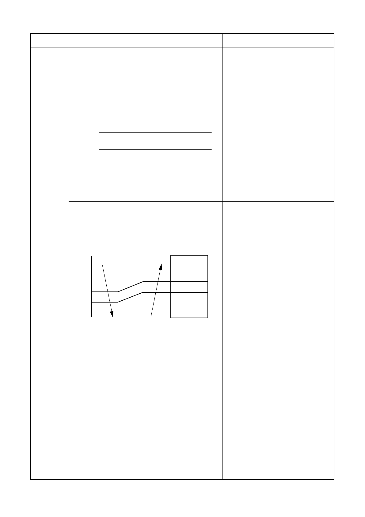
3. AUTO operation
Selection of operation mode
As shown in the following figure, the operation starts by
selecting automatically the status of room temperature
(Ta) when starting AUTO operation.
*1. When reselecting the operation mode, the fan
speed is controlled by the previous operation mode.
Ta
Cooling operation
Ts + 1
Monitoring (Fan)
Ts – 1
Heating operation
4. DRY operation
DRY operation is performed according to the difference
between room temperature and the setup temperature as
shown below.
In DRY operation, fan speed is controlled in order to
prevent lowering of the room temperature and to avoid air
flow from blowing directly to persons.
[°C]
+
+
Ta
1.0
0.5
L– (W5)
(W5+W3) / 2
SUL (W3)
Tsc
Fan speed
Description
Detects the room temperature (Ta) when
1)
the operation started.
2) Selects an operation mode from Ta in
the left figure.
3) Fan operation continues until an
operation mode is selected.
4) When AUTO operation has started
within 2 hours after heating operation
stopped and if the room temperature is
20°C or more, the fan operation is
performed with ”Super Ultra LOW” mode
for 3 minutes.
Then, select an operation mode.
In AUTO mode, either cooling or heating
5)
operation will be selected. When room
temperature reach set temperature
commpressor will stop. In case that the
compressor stops for 15 minutes, the
AUTO mode will reselect cooling or
heating operation.
1) Detects the room temperature (Ta) when
the DRY operation started.
2) Starts operation under conditions in the
left figure according to the temperature
difference between the room temperature and the setup temperature (Tsc).
Setup temperature (Tsc)
= Set temperature on remote controller
(Ts) + (0.0 to 1.0)
3) When the room temperature is lower
1°C or less than the setup temperature,
turn off the compressor.
− 28 −
FILE NO. SVM-14017
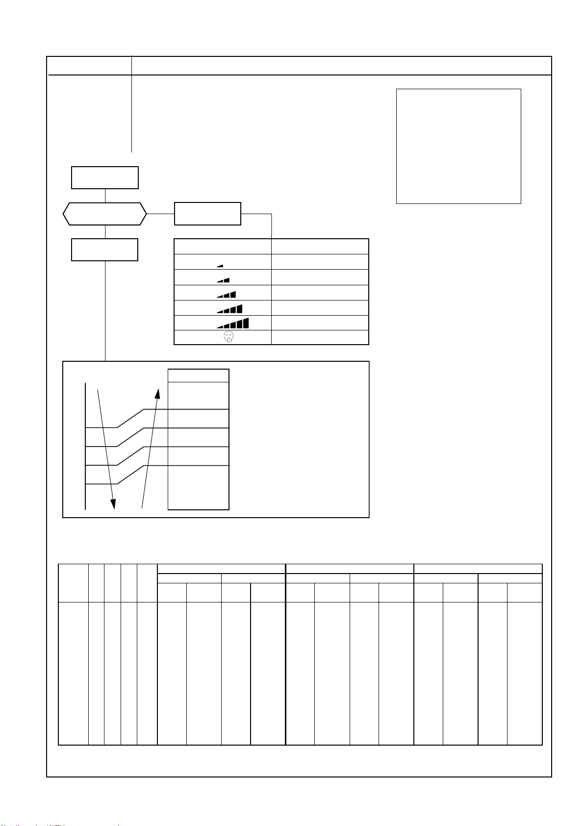
Item
2. Indoor fan
motor control
COOL ON
Fan speed setup
AUTO
Ta
[°C]
+2.5
a
+2.0
b
+1.5
c
+1.0
Operation flow and applicable data, etc.
<In cooling operation>
(This operation controls the fan speed at indoor unit side.)
The indoor fan (cross flow fan) is operated by the phase-
control induction motor. The fan rotates in 5 stages in
MANUAL mode, and in 5 stages in AUTO mode, respectively. (Table 1)
MANUAL
(Fig. 1)
Indication
L
L+
M
M+
H
Quiet
Fan speed
W7
(L + M) / 2
WA
(M + H) / 2
WD
W5
(Fig. 2)
Air volume AUTO
M+(WC)
*3
*4
*5
*3 : Fan speed = (M + –L) x 3/4 + L
*4 : Fan speed = (M + –L) x 2/4 + L
*5 : Fan speed = (M + –L) x 1/4 + L
Description
* Symbols
UH : Ultra High
H : High
M+ : Medium+
M : Medium
L+ : Low+
L: Low
L- : Low–
UL : Ultra Low
SUL : Super Ultra Low
* The values of fan speed and air flow
volume indicate on the table are
measured when the louver is inclined
downward. Fan speed and air flow
volume broadly vary with position
of louver.
1) When setting the fan speed to L,
L+, M, M+,H or Quiet on the
remote controller, the operation is
performed with the constant
speed shown in Fig. 1.
2) When setting the fan speed to
AUTO on the remote controller,
revolution of the fan motor is
controlled to the fan speed level
shown in Fig. 2 and Table 1
according to the setup temperature, room temperature, and heat
exchanger temperature.
d
+0.5
Tsc
e
L(W7)
(Table 1) Indoor fan air flow rate
Fan speed
Level
WF
WE
WD
WC
WB
WA
W9
W8
W7
W6
W5
W4
W3
W2
W1
Cool Heat PAP Dry
UH UH/H
UH H
H M+ UH
M+ M+ H
M M+
M M/L+ M
L+
L+ L L+
L L- L
L- L
UL UL L- L-
SUL UL
SUL SL
SUL/SL-
SL-
UL
Cooling Heating Cooling Heating Cooling Heating
Fan speed Air Flow rate Fan speed Air Flow rate Fan speed Air Flow rate Fan speed Air Flow rate Fan speed Air Flow rate Fan speed Air Flow rate
(rpm)
1060 661 1080 676 1100 690 1140 731 1120 713 1160 746
1060 661 1080 676 1100 698 1140 731 1120 713 1160 746
1040 647 930 551 1080 676 990 611 1100 690 1010 621
900 527 930 551 930 551 990 611 950 567 1010 621
900 527 780 423 930 551 840 475 950 567 860 493
760 409 780 423 780 423 840 475 800 442 860 493
760 409 710 368 780 423 750 401 800 442 770 416
690 349 640 305 710 368 660 322 730 384 680 338
620 287 560 243 640 305 600 274 660 322 620 287
520 205 560 243 560 243 600 274 580 255 620 287
500 187 540 224 540 224 580 255 560 243 600 274
480 173 500 187 520 205 560 243 540 224 580 255
460 155 480 173 500 187 540 224 520 205 560 243
450 147 460 155 480 173 520 205 500 187 540 224
440 142 440 142 440 142 440 142 440 142 440 142
(Linear approximation
from M+ and L)
RAS-10G2KVP-E RAS-13G2KVP-E RAS-16G2KVP-E
(m3/h)
(rpm)
(m3/h)
(rpm)
(m3/h)
(rpm)
(m3/h)
(rpm)
(m3/h)
(rpm)
(m3/h)
– 29 –

d
O
ol
y.
c
e
C
[C]
b
5
c
5.5
)
)
U
.
)
ON
t
FILE NO. SVM-14017
Item
2. Indoor fan
motor control
HEAT
Fan speed setup
AUTO
TC ≥ 42°C
NO
Operation flow and applicable data, etc.
<In heating operation>
MANUAL
Indication Fan speed
L
L+
M
M+
H
Quiet
YES
Tc
51
50
(Fig. 3)
(L + M) / 2
(M + H) / 2
W
Min air flow rate control
M+ (WC)
W8
WB
WE
Description
1) When setting the fan speed to L,
L+, M, M+, H or Quiet on the remote
controller
, the operation is performed with the constant speed
shown in Fig. 3 and Table 1.
2) When setting the fan speed to
AUTO on the remote controller,
revolution of the fan motor is
controlled to the fan speed level
shown in Fig. 5 according to the set
temperature and room temperature.
3) Min air flow rate is controlled by
temperature of the indoor heat
exchanger (Tc) as shown in Fig. 4.
4) Cold draft prevention, the fan
speed is controlled by temperature
of the indoor heat exchanger (Tc)
5
as shown in Fig. 6.
5) In order to prevent Cold draft when
compressor step during heating
operation. Then louver will move to
upper position and fan speed will
reduce or off.
* Fan speed=
(Fig. 4)
Basic fan contr
A
TS
–0.
d
–1.0
e
–1.5
f
–2.0
g
–2.5
–5.0
*
1: Fan speed = (M + -L+) x 1 5 + L+
2: Fan speed = (M + -L+) x 2 5 + L+
*
3: Fan speed = (M + -L+) x 3 5 + L+
*
4: Fan speed = (M + -L+) x 4 5 + L+
*
(TC – (41+a)) / (51 − 41) x (M+ −L ) + L
Fan spee
AUT
L+ (W9)
*1
*2
*3
*
4
H (WE
(Calculated with linear approximation from M+ and L+)
(Fig. 5)
No limi
Cold draft preventive control
Tc
45
44 32
33 21
32 20
*A+4 *A+4
*A-4 *
* No limitation while fan speed MANUAL mode is in stabilit
* A: When Tsc 24, A is 24, and when Tsc < 24, A is Ts
Tsc: Set valu
33
A-8
Fan speed MANUAL in starting
Fan speed AUTO in stability and stability
H (WE
Line-approximate
H and S
SUL (W2
Stop
L with Tc
(Fig. 6)
[[In starting and in stability]
In starting In stability
FAN AUTO
FAN Manual •
Until 12 minutes
•
When
12 to 25 minutes passed after operation
•
passed aft
start and room temperature is 3°C or lower than
set temperature.
Room temperature < Set temperature –4°C
er
operation
star
t
•
When 12 to 25 mi nutes passed after operation start
and room temperature is higher than (set temperature
–3°C)
• When 25 minutes or more passed after operation start
• Room temperature ≥ Set temperat ure –3.5°C
– 30 –

FILE NO. SVM-14017
Item
3. Outdoor fan
motor control
1) Outdoor unit
Operation flow and applicable data, etc.
The blowing air volume at the outdoor unit side is controlled.
Receiving the operation command from the controller of
indoor unit, the controller of outdoor unit controls fan speed.
* For the fan motor, a DC motor with non-stage variable
speed system is used. However, it is limited to 8 stages for
reasons of controlling.
Air conditioner ON
(Remote controller)
Indoor unit controller
operation command
(Outdoor fan control)
2) Fan speed ≥ 400.
when the motor OFF.
(by strong wind)
YES
Fan motor OFF continues
(Use wind for heat
exchanging)
NO
Fan motor ON
Description
1) The operation command sent
from the remote controller is
processed by the indoor unit
controller and transferred to the
controller of the outdoor unit.
2) When strong wind blows at
outdoor side, the operation of air
conditioner continues with the
fan motor stopped.
3) Whether the fan is locked or not
is detected, and the operation of
air conditioner stops and an
alarm is displayed if the fan is
locked.
4) According to each operation
mode, by the conditions of
outdoor temperature (To) and
compressor revolution, the speed
of the outdoor fan shown in the
table is selected.
3) Fan lock
YES
Air conditioner
OFF
NO
4)
Motor operates as shown in the table below.
In Cooling operation In Heating operation
Compressor speed (Hz)
To ≥ 38°C W6 WB W8 WE WA WE To ≥ 5 °C W9 WB WE
To ≥ 29°C W5 WA W7 WE W9 WE To ≥ -3°C WE WE WE
To
When To is abnormal OFF WB OFF WE W1 WE
To ≥ 15°C W3 W7 W5 W9 W7 WB To ≥ -10°C WE WE WE
To ≥ 5°C W2 W5 W4 W7 W6 W9 To < -10°C WE WE WE
To ≥ 0°C W1 W3 W3 W5 W4 W7 When To is abnormal WE WE WE
To ≥ -4°C W1 W2 W2 W4 W3 W5
To < -4°C OFF OFF OFF W3 W1 W4
Hz < 13.8 13.8 ≤ Hz ≤ 32.4 32.4 < Hz
MIN MAX MIN MAX MIN MAX
Compressor speed (Hz)
TO
Outdoor fan speed (rpm)
Ta
RAS-10G2AVP-E
p
RAS-13G2AVP-E
W0 0 0 0
W1
W2
W3
W4
W5
W6
W7
W8
250 250 250
310 300 310
380 350 380
430 450 430
470 500 470
550 560 550
610 600 610
610 650 640
RAS-16G2AVP-E
Tap
W9
WA
WB
WC
WD
WE
WF
Alarm
display
Hz < 16.8
To≥10°C W7 W8 W9
RAS-10G2AVP-E
610 700 700
610 700 750
610 700 800
610 700 800
610 700 800
610 700 800
700 850 800
16.8 ≤
RAS-13G2AVP-E
Hz ≤ 47.4
RAS-16G2AVP-E
47.4 < Hz
– 31 –

FILE NO. SVM-14017
Item
4. Capacity
control
Remote controller
The cooling or heating capacity depending on the load is
adjusted.
According to difference between the setup value of temperature and the room temperature, the capacity is adjusted by
the compressor revolution.
Set temp. (Ts)
Detection of motor speed (Operation Hz)
Correction value of Hz signal- Operating Hz
Operation flow and applicable data, etc.
Indoor unit
Room temp. (Ta)
Ts −Ta
Correction value of Hz signal
Detection of electromotive force
of compressor motor winding
and rotor position
Inverter output change
Commutation timing change
Description
1) The difference between set
ature on remote controller
temper
(Ts) and room temperature (Ta)
is calculated.
2) According to the temperature
difference, the correction value of
Hz signal which determines the
compressor speed is set up.
3) The rotating position and speed
of the motor are detected by the
electromotive force occurred on
the motor winding with operation
of the compressor.
4) According to the difference
resulted from comparison of the
correction value of Hz signal with
the present operation Hz, the
inverter output and the commutation timing are varied.
5) Change the compressor motor
speed by outputting power to the
compressor.
* The contents of control
operation are same in cooling
operation and heating
operation
5. Current release
control
This function prevents troubles on the electronic parts of the
compressor dr
This function also controls dr
speed so that electric power of the compressor drive circuit
does not exceed the specified value.
Outdoor unit inverter main
circuit control current
Operating current ≤
Setup value
Low
Capacity control continues.
Outdoor temp.
45ºC
40ºC
16ºC
11ºC
44ºC
15.5ºC
10.5ºC
Change of compressor speed
iving inverter.
High
Cooling current release value
RAS-10G2AVP-E
4.6A
6.0A
39ºC
6.6A
ive circuit of the compressor
Outdoor temp. To
Setup of current release point
Reduce compressor speed
Current decrease
Heating current release value
RAS-13G2AVP-E
RAS-16G2AVP-E
6.5A
6.8A
8.5A
RAS-10G2AVP-E
10.8A
1) The input current of the outdoor
unit is detected in the inverter
section of the outdoor unit.
According to the detected
2)
outdoor temperature, the
specifice value of the current is
selected.
3) Whether the current value
exceeds the specifice value or
not is judged.
4) If the current value exceeds the
specified value,
this function
reduces the compressor speed
and controls speed up to the
closest one commanded from the
indoor unit within the range
which does not exceed the
specified value.
RAS-13G2AVP-E
RAS-16G2AVP-E
10.8A
– 32 –

FILE NO. SVM-14017
Item
6. Release protective
control by temperature of indoor heat
exchanger
7°C
6°C
5°C
Indoor heat exchanger temperature
Operation flow and applicable data, etc.
<In cooling/dry operation>
(Prevent-freezing control for indoor heat exchanger)
In cooling/dry operation, the sensor of indoor heat
exchanger detects evaporation temperature and
controls the compressor speed so that temperature of
the heat exchanger does not exceed the specified
value.
Usual cooling capacity control
R
When the value is
in Q zone, the
Q
compressor speed
is kept.
P
Reduction of compressor speed
Description
1) When temperature of the indoor
heat exchanger drops below 5°C,
the compressor speed is
reduced. (P zone)
2) When temperature of the indoor
heat exchanger rises in the
range from 6°C to under 7°C, the
compressor speed is kept.
(Q zone)
3) When temperature of the indoor
heat exchanger rises to 7°C or
higher, the capacity control
operation returns to the usual
control in cooling operation.
(R zone)
55°C
52°C
48°C
Indoor heat exchanger temperature
<In heating operation>
(Prevent-overpressure control for refrigerating cycle)
In heating operation, the sensor of indoor heat ex-
changer detects condensation temperature and controls
the compressor speed so that temperature of the heat
exchanger does not exceed the specified value.
Reduction of compressor speed
P
When the value is
Q
in Q zone, the
compressor speed
is kept.
R
Usual heating capacity control
1) When temperature of the indoor
heat exchanger rises in the
range from 52°C to 55°C, the
compressor speed is kept.
(Q zone)
When temperature of the indoor
heat exchanger drops in the
range from 48°C to under 55°C,
the compressor speed is kept.
(Q zone)
2) When temperature of the indoor
heat exchanger rises to 55°C or
higher, the compressor speed is
reduced. (P zone)
3) When temperature of the indoor
heat exchanger does not rise to
52°C, or when it drops below to
48°C, the capacity control
operation returns to the usual
control in heating operation.
(R zone)
– 33 –

FILE NO. SVM-14017
Item Operation flow and applicable data, etc. Description
7. Defrost control
(Only in heating
operation)
Start of heating operation
-3°C
-7°C
-13°C
-25°C
Outdoor heat exchanger temperature
Table 1
A zone
B zone
C zone
D zone
(This function removes frost adhered to the outdoor
heat exchanger.)
The temperature sensor of the outdoor heat exchanger (Te sensor) judges the frosting status of the
outdoor heat exchanger and the defrost operation is
performed with 4-way valve reverse defrost system.
Operation time
(Minute)
0' 10' 15'
*
29'
35'
B Zone
C Zone
70'
A Zone
D Zone
* The minimum value of Te sensor 10 to 15 minutes
after start of operation is stored in memory as Te0.
When (TE0 - TE) - (TO0 - TO) ≥ 3°C and SH-SHO ≤ 2
in A zone, defrost operation starts.
When (TE0 - TE) - (TO0 - TO) ≥ 2°C and SH-SHO ≤ 2
in B zone, defrost operation starts.
When TE ≤ -25°C and SH-SHO ≤ 2 in C zone,
defrost operation starts.
More than 70 minutes accumulated heating
operation time condition TE < -13°C
The necessity of defrost operation is
detected by the outdoor heat exchanger
temperature. The conditions to detect the
necessity of defrost operation differ in A,
B, or C zone each. (Table 1)
<Defrost operation>
• Defrost operation in A to C zones
1) Stop operation of the compressor for
20 seconds.
2) Invert (ON) 4-way valve 10 seconds
after stop of the compressor.
3) The outdoor fan stops at the same time
when the compressor stops.
4) When temperature of the indoor heat
exchanger becomes 38°C or lower,
stop the indoor fan.
<Finish of defrost operation>
• Returning conditions from defrost
operation to heating operation
Temperature of outdoor heat exchanger
1)
rises to +8°C or higher.
Temperature of outdoor heat exchanger is
2)
kept at +5°C or higher for 80 seconds.
3)
Defrost operation continues for
15 minutes.
<Returning from defrost operation>
1) Stop operation of the compressor for
approx. 50 seconds.
2) Invert (OFF) 4-way valve approx. 40
seconds after stop of the compressor.
3) The outdoor fan starts rotating at the
same time when the compressor starts.
•
Strong defrost
Upgrade defrost ability when normal defrost ability
is not enough by increase defrosting finished
operation.
•
Do cut the jumper J803 on CDU PCB
J804
Finish of defrost operation for strong
<
defrost
•
>
Returning conditions from defrost
operation to heating operation
1)
Temperature of outdoor heat exchanger
rises to +13°C or higher.
2)
Temperature of outdoor heat exchanger is
kept at +10°C or higher for 80 seconds.
Defrost operation continues for
3)
20 minutes.
– 34 –

FILE NO. SVM-14017
Item
7. Defrost control
(Only in heating
operation)
Operation flow and applicable data, etc. Description
On demand defrost
•
In certain extreme condition, one can manually
defrost at any time by pressing button on the
remote controller.
<On demand defrost setting>
In AUTO or Heat mode, pass SET
button and hold for 5 seconds
this function activate, DF will be shown
on display.
PRESET
PURE
TEMP.
C
SET
. When
− 35−

FILE NO. SVM-14017
Item
8. Louver control
1) Louver
position
This function controls the air direction of the indoor unit.
• The position is automatically controlled according to the operation
mode (COOL/HEAT).
Operation flow and applicable data, etc.
• The set louver position is stored in memory by the microcomputer,
and the louver returns to the stored position when the next operation
is performed. (Cooling/Heating memory position)
The angle of the louver is indicated as the louver closes fully is 0°.
1) Louver position in cooling operation
Manual and automatic operation HI-POWER operation
Initial setting is directs downward (13.4°) Default setting is directs downward (26.1°)
Wide air direction
Description
Wide-angle Right wide Left wide
Left side lover setting is left facing (45.9°)
Right side lover setting is right facing (45.9°)
Wide front Sport right Spot left
Wide position is directs downward (13.4°)
Left side lover setting is front facing (0°)
Right side lover setting is right facing (45.9°)
Spot air direction
Spot position is directs downward (43.1°)
Left side lover setting is left facing (45.9°)
Right side lover setting is front facing (0°)
Left side lover setting is front facing (0°)
Right side lover setting is front facing (0°)
Left side lover setting is right facing (45.9°)
Right side lover setting is right facing (45.9°)
– 36 –
Left side lover setting is left facing (45.9°)
Right side lover setting is left facing (45.9°)

FILE NO. SVM-14017
Item
8. Louver control
Manual and automatic operation HI-POWER operation
Initial setting is directs downward (43.1°) Default setting is directs downward (26.1°)
2) Louver position in heating operation
Wide-angle Right wide Left wide
Operation flow and applicable data, etc. Description
Wide air direction
Wide position is directs downward (43.1°)
Left side lover setting is left facing (45.9°)
Right side lover setting is right facing (45.9°)
Wide front Sport right Spot left
Left side lover setting is front facing (0°)
Right side lover setting is front facing (0°)
Left side lover setting is front facing (0°)
Right side lover setting is right facing (45.9°)
Spot air direction
Spot position is directs downward (43.1°)
Left side lover setting is right facing (45.9°)
Right side lover setting is right facing (45.9°)
Left side lover setting is left facing (45.9°)
Right side lover setting is front facing (0°)
Left side lover setting is left facing (45.9°)
Right side lover setting is left facing (45.9°)
– 37 –

FILE NO. SVM-14017
Item
8. Louver control
Wind direction adjustment
2)
Horizotal blowing Inclined blowing
Inclined blowing Blowing downward
Operation flow and applicable data, etc. Description
The Up-Down louver
•
position can be
arbitrarily set up by
pressing [FIX
The Left-Right louver
•
] button.
position can be
arbitrarily set
up by
pressing [FIX ] button.
3) Swing
Front blowing Left blowing
Right blowing Front blowing
• Swing operation is perfor in range 35° with the Fixed position as
the center.
• If the swing range exceeded either upper or lower limit position,
swing operation is perfomed in range 35° from the limit.
Upper Limit
Position.
Swing
o
range 35
Fixed Position
before start
swing.
o
17.5
17.5
Lower Limit
Position.
o
Upper Limit
Position.
Fixed
Position
before start
swing
Swing
range 35
o
5
o
30
o
Lower Limit
Position
Swing
•
When pressing
[SWING] button during
operation, the louver
starts swinging.
Up-Down and Left-Right
•
louver are same setting.
– 38 –

FILE NO. SVM-14017
A
Item
9. ECO
operation
°C
6.5
6.0
5.5
5.0
4.5
4.0
3.5
3.0
2.5
2.0
1.5
1.0
0.5
TSC
(Room temp. – Set temp.)
-0.5
-1.0
-2.0
Operation flow and applicable data, etc.
When pressing [ECO] button on the remote controller, a
Economic operation is performed.
<Cooling operation>
This function operates the air conditioner with the difference
between the set and the room temperature as shown in the
following figure.
Frequency
Zone
12
Dry Max
11
*12
*11
10
*10
9
*
9
8
7
*8
6
5
4
3
2
Min
1
Hz
OFF
Description
<Cooling operation>
1) The control target temperature
increase 0.5ºC per hour up to 2ºC
starting from the set temperature
when ECONO has been received.
2) The indoor fan speed is depend
on presetting and can change
every speed after setting ECO
FAN
operation.
3) The compressor speed is
controlled as shown in the left
figure.
during the ECO operation.
The indoor fan speed is not controlled and can be selected
1H 2H
3H
* 12 (DRY max - COOL min) /6 x 5 + COOL min
* 11 (DRY max - COOL min) /6 x 4 + COOL min
* 10 (DRY max - COOL min) /6 x 3 + COOL min
*9 (DRY max - COOL min) /6 x 2 + COOL min
* 8 (DRY max - COOL min) /6 x 1 + COOL min
Hz 10G2KVP-E 13G2KVP-E 16G2KVP-E
Cool min 10 9 9
DRY max 30 30 30
< Heating Operation >
°C
0.0
1.0
2.0
3.0
4.0
5.0
6.0
7.0
8.0
Room temp. - Set temp.
9.0
10.0
11.0
12.0
ECO Start 30 minutes Time
Zone
B Zone
C Zone
Compressor stop
A Zone
B Zone
4H
C Zone
Time
<Heating operation>
1) The difference of room temperature
and set temperature are separated
in to A zone, B zone and C zone.
Three zone will changed again 30
minutes after ECO operation start.
2) The compressor speed is
controlled as shown on the table.
3) The indoor fan speed is not
controlled and can be selected
during the ECO operation.
Hz 10G2KVP-E 13G2KVP-E 16G2KVP-E
a (Heating min Hz) 9 9 9
c (HEATING Quiet) 30 30 30
– 39 –

FILE NO. SVM-14017
Item
10. Temporary
operation
Operation flow and applicable data, etc.
Pressing [RESET] button starts the temporary operation of [AUTO] operation. When keeping [RESET]
button pressed for 10 seconds or more, the temporary
[COOL] operation is performed.
Filter lamp ON
NO
Did you press [RESET] button
for 3 seconds or more?
YES
Did you press [RESET] button
for 10 seconds or more?
NO
Switch to [AUTO RESTART] control.
11.
Plasma
ionizer
purifier
control
This function generates nagative ion while cleaning the air in the room.
If plasma ionizer purifier-ON signal is received while the air conditioner stops, the plasma ionizer
purifier starts operation, and if it is received while the air conditioner operates, the air conditioner
and the plasma ionizer purifier start operation.
YES
NO
Press RESET button.
Temporary [AUTO] operation
YES
Temporary [COOL] Operation
Description
1) When pressing [RESET] button, the
temporary [AUTO] operation starts.
2) When keeping [RESET] button pressed
for 3 seconds or more, Pi, Pi, Pi sound is
heard and [AUTO RESTART] control is
changed.
3) When keeping [RESET] button pressed
for 10 seconds or more, “Pi” sound is
heard and the temporary [COOL]
operation starts.
4) If the filter lamp goes on, press [RESET]
button to go off the filter lamp, and then
press [RESET] button again.
5) To stop the temporary operation, press
the button again.
Present status
Stop
Plasma ionizer purifier only
Air conditioner
Joint use of AC and plasma ionizer purifier
Plasma ionizer purifier operation
AC + Plasma ionizer purifie operation
Sending plasma ionizer-ON
1
Air conditioner stops
Operation lamp ON
Memory position of
louver/COOL
1,2
*1
Operation button
PURE button Air conditioner
Plasma ionizer purifier
Stop (All)
AC + Plasma ionizer purifier
AC operation All stop
Louver*1
Cooling position
Follows to AC operation
2
Air conditioner operates
Start of plasma ionizer purifier-ON
Air conditioner + Plasma
ionizer purifier operate
AC operation*
AC + Plasma ionizer purifier
All stop
Fan speed *2
AUTO, L, L+, M, M+, H
Follows to AC operation
Plasma ionizer purifier
Operation lamp OFF Filter-OFF
* When the previous operation was the
operation of air conditioner + plasma
ionizer purifier, an operation of air
conditioner + plasma ionizer purifier starts
by pushing AC button on the remote
controller.
(Operation of air conditioner + plasma
ionizer purifier is stored in memory.)
*1 Swing is available
*2 Fan speed is Fan Auto mode varies in
order, (M + 1) → (L) → (L–) → (SL).
Sending plasma ionizer purifier-OFF
,
3
3
operates
Fan stop
4
Plasma ionizer purifier
Air conditioner operates
4
Air conditioner +
operate
*2
Fan ON
Plasma ionizer purifier ON
Plasma ionizer purifier operation
Plasma ionizer purifier-OFF
Louver close
All stop
– 40 –

FILE NO. SVM-14017
Item Operation flow and applicable data, etc. Description
11. Plasma ionizer purifier control [Detection of abnormality]
Plasma ionizer purifier operation
Plasma ionizer purifier power ON
Error input
Plasma ionizer purifier
power ON 1 minute or
less
Plasma ionizer purifier
lamp brink
Plasma ionizer purifier
power OFF
NO
NO
Plasma ionizer purifier
Plasma ionizer purifier
Plasma ionizer purifier
power ON after 10
minutes from the error
Error input 5 times
Plasma ionizer purifier
lamp
power OFF
input.
power OFF
Reset
Reset by RESET button or by the stop direction
from the remote controller.
NO
1. Purpose
The air purifying control function is to
alert the user to trouble in the ionizing or
plasma ionixer purifier operation.
2. Description
Trouble is determined to have occurred
(indicated by the plasma ionizer purifier
lamp indicator) in the following
two cases.
1) When the panel switch has been set to
OFF by the opening of the air inlet
grile, etc.
2) When an abnormal discharge caused
by a symptom such as the build-up of
dirt has been detected while the air
purifier is ON
*
Trouble case are deemed to have
occurred when the action
concerned continues for more than
one second.
3. Operation
The sequence that plasma ionizer
purifier lamp indicator is turned on are
described in the left flowchart.
1) A trouble detected within 1 minute
after activation of the air is
immedi-ately judged as an error
and the plasma ionizer purifier
lamp indicator goes on.
2) In case that 1 minute passed after
activation of the plasma ionizer
purifier, it is turned off while the
PURE indicator keeps ON. After 10
minutes passed, restart the plasma
ionizer purifier and an error is judged
again.
When the breaker is turned [ON] (In restart time
*
after power failure) or RESET button is pressed
the air purifier is not turned on until the integrated
operation time of the indoor fan exceeds 1 hour
after operation start (It is nor the Plasma ionizer
purifier operation time).
It is the safety measures considering an incomplete drain when electric dust collector has been
cleaned with water.
12. Discharge temperature control
Td value
117°C
105°C
103°C
100°C
93°C
Judges as an error and stops the compressor.
Reduce the compressor speed.
Reduce slowly compressor speed.
Keeps the compressor speed.
If the operation is performed with lower speed than one
commanded by the serial signal, speed is slowly raised
up to the commanded speed.
Operates with speed commanded by the serial signal.
Control operation
1. Purpose
This function detects error on the
refrigerating cycle or error on the compressor, and performs protective control.
2. Operation
Control of the compressor speed
The speed control is performed as
described in the left table based upon
the discharge temperature.
– 41 –

FILE NO. SVM-14017
Item Operation flow and applicable data, etc.
13. High pressure control 1. Purpose
This function detects error on the
Cooling
(TE)
63°C
63°C
61°C
59°C
55°C
Pulse
14.
Modulating
valve (P.M.V.)
control
SH control
Heating
(TC)
52°C
57°C
55°C
53°C
49°C
Control operation
This function controls throttle amount of the
refrigerant in the refrigerating cycle.
According to operating status of the air conditioner,
this function also controls the open degree of valve
with an expansion valve with pulse Modulation.
Starting up
Initialize
Move to
initial position
Compressor ON
Td, high pressure
release control
refrigerating cycle or error on the compressor, and performs protective control.
2. Operation
Control of the compressor speed The
speed control is performed as described in
the left table
exchanger temperature (TE, TC).
1) When starting the operation, move the
valve once until it fits to the stopper.
(Initialize)
* In this time, “Click” sound may be
heard.
2) Adjust the open degree of valve by super
heat amount. (SH control)
3) If the discharge temperature was excessively up, adjust the open degree of valve
so that it is in the range of set temperature. (Discharge temp. control)
4) When defrost operation is performed, the
open degree of valve is adjusted according to each setup conditions during
preparation for defrost and during defrost
operation (4-way valve is inversed.).
5) When operation is OFF by the remote
controller or when compressor is OFF by
room temperature control, the open
degree of valve is adjusted to the stop
position.
Description
based upon the heat
PMV open degree control
Turn OFF by
remote controller
Compressor Stop by
"Room Temperature
Control"
Move to "Stop
Position" (Setup
from factory)
* SH (Super Heat amount) =
Ts (Temperature of suction pipe of the compressor) –
Tc or Te (Heat exchanger temperature at evaporation side)
* PMV: Pulse Modulating Valve
Defrosting
operation
Move to "Defrost
Position" (Setup
from factory)
– 42 –

FILE NO. SVM-14017
Item
Operation flow and applicable data, etc.
15. Self-Cleaning
function
Unit now performing cooling or dry operation
Press “STOP” button
Only timer indicator lights, and Self Cleaning operation starts
Time set now elapses
Operation stops
Description
1. Purpose
The Self-Cleaning operation is to minimize the
growth of mold, bacteria etc. by running
the fan and drying so as to keep the
inside of the air conditioner clean.
Self-Cleaning operation
When the cooling or dry operation shuts
down, the unit automatically starts the Self-
Cleaning operation which is then performed
for the specified period based on duration
of the operation which was performed
prior to the shutdown, after which the
Self-Cleaning operation stops.
(The Self-Cleaning operation is not
performed after a heating operation.)
2. Operation
1) When the stop signal from the remote
controller or timer-off function is received,
only the timer indicator light.
2) The period of the Self-Cleaning operation
is determined by the duration of the
operation performed prior to the
reception of the stop code.
3) After the Self-Cleaning operation has
been performed for the specified period,
the unit stops operating.
• During Self-Cleaning operations: The louver opens
slightly. The indoor fan operates continuously at
a speed of 500 rpm.
Self-Cleaning operation times
Self-Cleaning operation time
No Self-Cleaning operation
performed (0 minutes)
30 mins.
operation performed
Cooling: Auto (cooling) Dry
Heating: Auto (heating)
Auto (fan only)
Shutdown
Operation time
Up to 10 minutes
10 minutes
or longer
No Self-Cleaning
• To stop an ongoing Self-Cleaning operation at any time
Press the start/stop button on the remote controller twice during the Self-Cleaning
operation. (After pressing the button for the first time, press it for the
second time without delay (within 10 minutes).)
– 43 –

FILE NO. SVM-14017
Item
Self-Cleaning
15.
function
15-1-1. Self-Cleaning diagram
Operation display ON OFF OFF
FCU fan
FCU louver OPEN OPEN (12.7º) CLOSE
Timer display
Compressor
CDU fan ON or OFF
depend on presetting of timer function. depend on presetting of timer function.
depend on presetting per room temperature.
depend on presetting per room temperature.
Operation flow and applicable data, etc.
rpm is depend on presetting. (500RPM)
Cool mode or dry mode
operation more than 10 mins.
ON ON
ON or OFF
ON or OFF
Self-Cleaning mode
Turn off by remote controller or
timer-off function.
ON
OFF OFF
OFF OFF
operate 30 mins.
Description
ON or OFF
Automatically turn-off.
OFF
Operation time
15-1-2. Self-Cleaning function release
How to set/cancel Self-Cleaning function
To set/cancel the Self-Cleaning function, proceed as
follows:
•
Setting diagnosis code "06" on remote controlle
(See detail of setting diagnosis code in 11-4-1)
• Turn on the power supply to air conditioner,
after that press [RESET] button on air conditioner
1 time to turn on the air conditioner (The LED
display will show in operation LED) (Fig. 15-1-1)
Take the remote controller to direction of LED
•
display on air conditioner, press button up
( ) at ON of the remote controller
(Fig. 15-1-2) 1 time to send the code "07"
(within 3 sec. after press [RESET] buton), then
air conditioner will shutdown automatically. Also,
LED display will show flash follow the able
below.
Self-cleaning
function
ON
OFF
Operation LED
flash 1 Hz
flash 1 Hz
Timer LED
not flash
Flash 1 Hz
•
Set or Cancel Self-Cleaning function by push
the RESET button on air conditioner.
When setting is changed, the sound warning will
alarm "Beep". The setting is changed following
below.
ON
OFF
ON
OFF
• Turn on air conditioner again by remote controller
to confirm setting.
Temporary switch
Fig. 15-1-1
Note) Table above will show current status of
Self-Cleaning function
Fig. 15-1-2
− 44 −

FILE NO. SVM-14017
Item
16.
Remote-A or B
selection
Operation flow and applicable data, etc.
Setting the remote controller
To separate using of remote control for each indoor
unit in case of 2 air conditioner are installed nearly.
Remote Control B Setup.
1) Press RESET button on the indoor unit to turn
the air conditioner ON.
2) Point the remote control at the indoor unit.
3) Push and hold CHK • button on the Remote
Control by the tip of the pencil. "00" will be shown
shown on the display.
4) Press MODE • during pushing CHK • . "B" will
show on the display and "00" will disappear and
the air conditioner will turn OFF. The Remote
Control B is memorized.
Note : 1. Repeat above step to reset Remote Control
to be A.
2. Remote Control A has not "A" display.
3. Default setting of Remote Control from
factory is A.
"00" display
"B" display
Description
1. Purpose
This operation is to operate only one
indoor unit using one remote controller.
2. Description
When operating one indoor unit in a
situation where two indoor units have
been installed in the same room or
nearby rooms, this operation prevents the
remote controller signal from being
received simultaneously by both units,
thus preventing both units from operating.
3. Operation
The indoor unit on which the remote
controller selection has been set to B
receives the signal of the remote controller also set to B.
(At the factory the remote controller
selection is set to A on all the indoor
units. There is no A setting display.)
17.
QUIET mode
18. COMFORT
SLEEP
When the [QUIET] selected form [Fan] button, the
fan of the indoor unit will be restricted the revolving
speed at speed UL until the [Fan] button is selected
other speed (cancel Quiet mode).
Cooling mode
• The preset temperature will increase as
show on ECO operation (Item No. 9)
• Press the [COMFORT SLEEP] button to
choose the operating hours. Repeat
pressing to select the hours.
(1hr, 3hr, 5hr or 9hr)
• If the [COMFORT SLEEP] button is pressed
again means cancel comfort sleep mode.
Heating mode
• The preset temperature will drop down as
show on ECO operation (Item No. 9)
• Press the [COMFORT SLEEP] button to
choose the operating hours. Repeat
pressing to setect thehours.
(1hr, 3hr, 5hr or 9 hr)
• If the [COMFORT SLEEP] button is pressed
again means cancel comfort sleep mode.
Quiet mode is the system which, control the
revolving speed of indoor fan to work
constantly at lower than speed L. In addition,
noise level of indoor unit is less than usual.
Remarks :
1. Quiet mode is unable to work in dry mode.
2. Quiet mode is appropriate to work with less
cooling load and less heating load condition.
Because of the fan speed may not enough
the cooling capacity or heating capacity.
The principles of comfort sleep mode are:
• Quietness for more comfortable. When
room temperature reach setting temperature
• Save energy by changing room temperature
automatically.
• The air condition can shut down by itself
automatically.
Remarks:
1. Comfort sleep mode will not operate in dry
mode and fan only mode.
− 45 −

FILE NO. SVM-14017
19.
Short Timer
Item
Operation flow and applicable data, etc.
In the normal condition, after switching one circuit
breaker, 3-minute delay time for compressor and
1 hour for plasma air purifier are set for the
maintenance of the unit.
PRESET
TEMP.
4
3
Description
Purpose
To start the unit immediately for the purpose of
testing, trial...etc, short timer can be used.
maintenance of the unit.
Short Timer Setting
j
Press [ ] button to turn the unit OFF.
k Set the operation mode or plasma air
purifier on the remote control without
sending the signal to the unit.
l Use the tip of the pencil to push the
[CHK] button and hold, "00" will show
on display, them press [SET] button
to make "00" disappear.
m
Press [ ] button to turn the unit ON.
n When short timer is activated, all
setting on the remote operates
immediately, besides, all indicatiors on
front panel turns ON continuously for
3 seconds.
Hi-POWER
20.
Mode
([Hi-POWER] button on the remote controller
is pressed)
When [Hi-POWER] button is pressed while the indoor
unit is in Auto, Cooling or Heating operation, HiPOWER mark is indicated on the display of the remote
controller and the unit operates as follows.
1. Automatic operation
• The indoor unit operates in according to the
current operation.
2. Cooling operation
The preset temperature drops 1ºC
•
(The value of the preset temperature on the
remote controller does not change.)
The indoor unit's fan speed level increase 1 tap
3. Heating operation
The preset temperature increases 2ºC
•
(The value of the preset temperature on the
remote controller does not change.)
The indoor unit's fan speed level increase 1 tap
4. The Hi-POWER mode can not be set in Dry
operation
∗ The Hi-POWER operation will be cancelled
when press [Hi-POWER] button again.
− 46 −

FILE NO. SVM-14017
21.
POWER
Selection
Mode
22.
Outdoor
Quiet
control
Item
Operation flow and applicable data,etc
([POWER-SEL] button on the remote controller
is pressed)
− Power Selection 75% is 75% of maximum
current.
− Power Selection 50% is 50% of rate maximum
current.
POWER-SELECTION OPERATION
POWER SEL
[100%] [75%] [50%] [100%]
<With Quiet control/Non-select method>
Select "Conrol" or "No conrol" by keeping
[RESET] button pushed for 20 seconds.
("No control" at shipment from the factory.)
Exchanging from "No control" to "Control" :
Beep sound is heard (Pi, Pi, Pi, Pi, Pi) and
the operation LED 5Hz flashes for 5
seconds.
Exchanging from "Control" to "No control" :
Beep sound is heard.
(Operation LED does not flash.)
POWER SEL
POWER SEL
POWER SEL
Description
1. Purpose
The function is used when its circuit
breaker is shared with other electrical
appliances. It limits the maximum
current/ power consumption to 100%,
75% or 50%.
The lower the percentage, the higher
the saving and also the longer the
compressor lifetime.
2. Description
When the level is selected, Power-SEL
level flashes on LCD display for 3
seconds. In case of 75% and 50%
level, number "75" or "50" also flashes
for 2 seconds.
Note :
Due to the reason that POWER
SELECT FUNCTION limits the
maximum current, inadequate
capacity may occur.
1. Purpose
For the users who concern about noise
of the outdoor unit, this control controls
the max. revolutions of the compressor
to reduce the noise.
2. Description
To reduce noise, [RESET] button of the
indoor unit is kept pushed for 20
seconds.
The number of revolution for the indoor
fan motor and the seup temp value are
kept as they are.
3. Operation
As shown in the table, the maximum
revolution number of indoor unit
compressor can be reduced.
As the maximum number of revolution
of the compressor is restricted, the rise-
up performance at the start time is
weakened.
.
<Maximum number of revolution of compressor at normal time and Quiet control time>
RAS-10G2KVP-E RAS-13G2KVP-E RAS-16G2KVP-E
Outside temp. Normail time Ouiet controlled Normail time Ouiet controlled Normail time Ouiet controlled
(TO) (rps) (rps) (rps) (rps) (rps) (rps)
COOL 61
~ 5°C 93 73 73 73 80 76
HEAT ~ 10°C-5°C
- 10°C ~ 93 73 73 73 80 76
93 73 73 73 80 76
53 58 58 78 64
− 47 −

FILE NO. SVM-14017
Item
Operation flow and applicable data,etc
23.FCU Display lamp brighness control
LAMP BRIGHTNESS ADJUSTMENT
While operating (Auto, Cool, Heat or Dry), select .
Rise
Press
Rremote control
LCD
or
Decrease
Lamp illuminates an operation with full brightness.
Lamp
illuminatesan
to adjust brightness which can be set at 4 levels or
to turn it off.
Operation display Brightness
operationwith50%brightness.
100%
50%
Description
Purpose
1.
It is necessary to decrease the
display lamp brightness or turn it
off.
.
In the examples of
•
Lamp
illuminatesan
operation mode lamp is turned off.
All lamps are turned off.
and
operationwith50%brightnessandthe
, the lamp illuminates for 5 seconds before going off.
50%
All turned off
− 48 −

FILE NO. SVM-14017
Operation
24.
mode
setectable
Item
Operation flow and applicable data,etc
Operating system setting
J804
•
Do cut J804 for cooling only systemp
•
Do cut J805 for heating only systemp
•
Do cut both of J804 and J805 for return
to factory default.
Description
1.
Purpose
Choosing the operating system as
appropriate in real condition
2.
Operation
Factory default setting prefer
"Heat pump" system. Through it is
able to cooling only system heating
only system or return to factory
default.
.
– 49 –

FILE NO. SVM-14017
9-3. Auto Restart Function
This indoor unit is equipped with an automatic restarting function which allows the unit to restart operating with
the set operating conditions in the event of a power supply being accidentally shut down.
The operation will resume without warning three minutes after power is restored.
This function is not set to work when shipped from the factory. Therefore it is necessary to set it to work.
9-3-1. How to Set the Auto Restart Function
To set Auto Restart Function, proceed as follows:
1. The power supply to the unit must be ON ; The function will not set or reset if the power supply is OFF.
2. Press the [RESET] button located on the front panel of the indoor unit for more than 3 seconds.
3. After 3 seconds, the unit beeps three times and the indicator blinks for 5 seconds.
• When the unit is standby (Not operating)
Operation
Press [RESET] button for more than
three seconds. (Less than 10 seconds)
Temporary switch
• When the unit is in operation
Operation
Press [RESET] button for more than
three seconds. (Less than 10 seconds)
Motions
The unit is on standby.
↓
The unit starts to operate. The green indicator is on.
↓ After approx. three seconds,
The unit beeps three times The green indicator flashes
and continues to operate. for 5 seconds.
If the unit is not required to operate at this time, press [RESET]
button once more or use the remote controller to turn it off.
Motions
The unit is in operation. The green indicator is on.
↓
The unit stops operating. The green indicator is turned off.
↓ After approx. three seconds,
The unit beeps three times. The green indicator flashes
for 5 seconds.
If the unit is required to operate at this time, press [RESET] button
once more or use the remote controller to turn it on.
Temporary switch
• While the filter check indicator is on, the RESET button has the function of filter reset betton.
– 50 –

FILE NO. SVM-14017
9-3-2. How to Cancel the Auto Restart Function
To cancel Auto Restart Function, proceed as follows.
1. The power supply to the unit must be ON ; The function will not set or reset if the power supply is OFF.
2. Press the [RESET] button located on the front panel of the indoor unit for more than 3 seconds.
3. After 3 seconds, the unit beeps three times.
• When the system is on stand-by (not operating)
Operation
Press [RESET] button for more than
three seconds. (Less than 10 seconds)
Temporary switch
• When the system is operating
Operation
Press [RESET] button for more than
three seconds. (Less than 10 seconds)
Motions
The unit is on standby.
↓
The unit starts to operate. The green indicator is on.
↓ After approx. three seconds,
The unit beeps three times and continues to operate.
If the unit is not required to operate at this time, press [RESET]
button once more or use the remote controller to turn it off.
Motions
The unit is in operation. The green indicator is on.
↓
The unit stops operating. The green indicator is turned off.
↓ After approx. three seconds,
The unit beeps three times.
If the unit is required to operate at this time, press [RESET] button
once more or use the remote controller to turn it on.
Temporary switch
9-3-3. Power Failure During Timer Operation
• If Timer operation is set and the power supply shut down accidentally, the previous Timer setting
will be cancelled.
• Daily-Timer operation will be not affected by power supply failure, if the remote controller is
located on the position which it can send the command signal to the indoor unit. It is because the remote
controller will send signal every 30 minutes and Daily-Timer operation will be restore.
– 51 –

9-4. Remote control
9-4-1. Remote control and its functions
1
Infrared signal emitter
2
Memory and preset button (PRESET) Start/Stop
3
button
4
Temperature up/down and Timer
or clock up/down button (TEMP.)
5
button (MODE)
6
Swing louver button (SWING)
7
Fan speed button (FAN)
8
Wide air flow, spot air flow (AIR FLOW)
9
Set louver button for vertical direction (FIX )
10
Set louver button for Horizontal divection (FIX )
11
8 degree celcius operation button (8°C) Economy
12
button (ECO)
13
High power button (Hi-POWER)
14
Plasma ionizer purifier button (PURE)
15
Comfort sleep button (COMFORT SLEEP)
16
Power selection button (POWER-SEL)
17
On timer button (ON)
18
Off timer button (OFF)
19
Setup button (SET)
20
Clear button (CLR)
21
Clock setup button (CLOCK)
22
Check button (CHECK)
23
Filter reset button (FILTER)
24
Reset button (RESET)
25
Weekly ON/OFF button ( )
Day button ( )
26
27
Temp for weekly timer button ( )
28
Program P1-P4 button ( )
-
Mode select
TEMP
FILE NO. SVM-14017
1
2
3
5
8
12
11
14
25
26
27
21
22
PRESET
TEMP.
TEMP
17
4
6
7
10
9
13
16
15
28
19
20
18
24
23
9-4-2. Operation of remote control
Weekly timer operation
1.
4 programs for each day in the week can be set in WEEKLY TIMER. The
following items can be set in WEEKLY TIMER operation.
a. Operation time (ON timer for Start and OFF timer for Stop operation)
b. Operation mode (COOL, DRY, HEAT, FAN ONLY)
c. Temperature setting.
d. Fan speed setting.
e. Special operation (8°C, ECO, Hi-POWER)
– 52 –

PRESET
8C
PURE
TEMP.
How to set WEEKLY TIMER
Press to enter WEEKLY TIMER setting.
1
Press to select desired day in sequence.
2
ThesequenceofdaysymbolappearsontheLCD
SU MO TU WE TH
WEEKLY SUMO
TUWETHFRSA
(All day)
FILE NO. SVM-14017
Blink
FR SA
3
4
Press to select the program number.
The program 1 is ready for setting while
•
LCD.
Press
•
Press
The time can be set between 0:00 and 23:50 in 10 minute intervals.
•
Press and hold the button to change setting time for 1 hr.
•
Only one of ON or OFF timer can be set on each program.
•
tochangetheprogramnumberinthesequenceprogram1toprogram4.
PG-1
PG- 2
PG- 3
PG- 4
or to select the desired time.
ispressedPG-1appearsonthe
ON timer display OFF timer display*
* OFF timer is used to stop the air conditioner only. The display does not
show Operation mode, Temperature, Fan speed and others.
– 53 –

5
FILE NO. SVM-14017
Press to select desired operation.
6
7
8
9
!
Press
The temperature can be set between 17°C and 30°C.
•
Press to select the desired fan speed.
Add operations, if required.
Press
•
Press
•
Press
•
Adding or editing the program.
Theprogramcanbesettoperformonalltherequireddaysuntil
confirm the setting !.
Ifaddingoreditingaprogramisrequired,pleaserepeatsteps2 - 8 before setting
confirmation.
After adding or editing, press to confirm the setting*.
or
TEMP.
to select desired temperature.
to use 8°C operation.
to use ECO operation
to use Hi-POWER operation.
Operating Mode
is pressed to
Weekly timer running
Next program
Timer ON or OFF
Next operation
time
*Point remote control at air conditioner receiving module then, press SET button until
you hear the “PiPi” sound. This means the setting operation has been completed.
As the air conditioner is receiving the signal, you will hear separate “Pi” sounds
corresponding to the number of days in the selected setting.
An incomplete setting is indicated if the TIMER lamp is blinking. Press
Notes
1. Place the remote control where the indoor unit can receive the signal. This will increase the accuracy of the timing between the remote control and the air
conditioning unit.
2. The ON/OFF timer can be set during the WEEKLY TIMER operation. In this situation, the air conditioner will first follow the normal timer until it is complete;
then, it will return to the WEEKLY TIMER function.
3. During WEEKLY TIMER operation, all of operation such as MODE, TEMP, FAN, Hi-POWER, ECO and etc., can be adjusted but when the clock reaches
the program setting, the operation will return to the set items in the program.
4. When the remote control is sending a signal to the air conditioner, avoid interference from objects that can block the signal.
Operating Temperature
and Fan speed
Display after
pressing SET
button
twice.
– 54 –

Edit Weekly timer program
FILE NO. SVM-14017
PRESET
8C
PURE
TEMP.
on below.
1
2
Page 21
Press
The day of the week and the program number of the current day will be displayed.
•
Press
Resetting the operation.
•
Press
.
to select the day of the week and press
to select program number to be confirmed.
to exit confirming mode.
, follow steps 1 - 3To edit the program after conflrming the weekly timer setting
3
Deactivating WEEKLY TIMER operation
Press while “WEEKLY” is displayed on the LCD.
The “WEEKLY” indicator will disappear from the LCD. However, the program will remain in the
•
remote control.
The TIMER lamp goes off.
•
To reactivate the WEEKLY TIMER operation again, press
•
program. The program, after reactivation, is related to the clock
time.
again, LCD shows the next
– 55 –

PRESET
TEMP.
To delete programs
The individual program
Press .
1
The day of the week and the program number is displayed.
•
Select the day to delete the program.
•
Press to select the program number to be deleted.
2
Press .
ON or OFF timer will be cleared and the LCD will blink.
3
•
FILE NO. SVM-14017
8C
PURE
Press
4
All programs
1
2
Make sure the remote control receiving module on the air conditioner receives the signal
from the remote control.
Press
•
Press .
The day of the week and the program number will be displayed.
•
Press and hold for 3 seconds.
All programs will be deleted and LCD displays current operation.
•
Notes
to delete the program.
while the LCD is blinking. The program has now been deleted.
– 56 –

2. AUTOMATIC OPERATION
To automatically select cooling, heating, or fan only operation.
1. PressPress : Sele
2. Press : Select the desired temperaPress
Press : Select AUTO, LOW , LOW+ , MED , MED+ , HIGH or Quiet
3. Press
3.
8°C OPERAT
1.1. P1. Press button to change to 8°C set temperature heating
2. Pre2. Press to adjust setting temperature from 5°C
Note: 8°C will operate in Heating mode only. If Air conditioner performs in cooling
operation (including automatic cooling) or dry operation it will change to
heating operation.
COOLING / HEATING / FAN ONLY OPERATION
4.
1. : Select Cool , Heat , or Fan only PressPress
2. : Set the desired temperaPressPress
Cooling: Min. 17°C, Heating : Max, 30°C, Fan Only: No temperature indication
: Select AUTO, LOW , LOW+ , MED , MED+
Press HIGH or Quiet
3.
Press
FILE NO. SVM-14017
Note :
QUIET is ultra low fan speed for quiet operation.
DRY OPERATION (COOLING ONL
5.
For dehumidification, a moderate cooling performance is controlled automatically.
. Pre1.1. Press : Select D
ss : Set the desired temperature.. Pre2.
PLASMA IONIZER PURIFIER OPERATION
6.
During air conditioner operation
Press PURE to start and plasma ionizer purifier operation.
The plasma air purifier and plasma ionizer purifier can be activated or deactivated during
air conditioner is stopped and the plama ionizer purifier starts in conjunction with plasma
plasma ionizer purifier operation.
Hi-POWER OPERATI
7.
To automatically control room temperature and airflow for faster cooling or heating
operation (except in DRY and FAN ONLY mode)
: Start and stop the operaPressPress
8. ECO OPERATION
To automatically control room to save energy (except in DRY and FAN ONLY mode)
Press : Start and stop the operation.
Note: Cooling operation; the set temperature will increase automatically 1 degree/
hour for 2 hours (maximum 2 degrees increase). For heating operation the
set temperature will decrease.
– 57 –

9.
AIR VOLUME, AIR DIRECTION AND SWING LOUVERS
•
Changing the air volume, press FAN button
•
Changing the air direction, press FIX button
FILE NO. SVM-14017
When changing the air to the
vertical direction, release the
left side at the desired position.
(
•
Changing the air direction, press FIX button
•
Movement of vertical air direction louvers
at the lower limit).
PiPi
Every time...
Pi
Vertical
(Up-Down)
Swing
Swing direction changes.
Cooling operation
Horizontal
(Left-Right)
Swing
When changing the air to the
horizontal position, release
the right side at the desired
position.
(
PiPi
Pi PiPi
Up-Down
Left-Right
Swing
(Default setting)
sounds at the front).
Swing
off
The shows
the range of air
flow direction
operation.
The range of
swing operation.
Louver for
air flow direction
up and down
Heating operation
Louver for
air flow
direction up
and down
(Default setting)
– 58 –

10.
COMFORT AIR FLOW
•
Wide air flow : Air flows around the room.
Spot air flow : Air flow is concentrated at one point.
•
While operating (Auto, Cool, Heat, Dry and these modes with PURE), Select
Every time...
•
When pressed, the air flow direction changes.
FILE NO. SVM-14017
Wide
center
Spot left
Cancel Air
Flow
Wide right
Spot right Spot
Wide left
center
11. TIMER OPERATION
Setting the ON Timer Setting the OFF Timer
Press for enter ON timer setting
1
Press for select desired ON
2
3
Press for set timer. Press for set timer.
4
Press for cancel timer. Press for cancel timer.
timer.
Press
Press for select desired OFF
for enter OFF timer setting
timer.
Daily timer allows the user to set both the ON & OFF timers and will be
activated on a daily basis.
Setting Daily T imer
1
Press for enter ON timer setting
Press for select desired
2
3
Press
ON timer.
for enter OFF timer setting
Press for select desired OFF
4
5
Press
Press again during the
6
( or ) blink.
timer.
• During the daily timer is activating, both arrows ( , ) are indicated.
Note:
· Keep the remote control in accessible transmission to the indoor unit
otherwise, the time lag of up to 15 minutes will occur.
· The setting will be saved for the next same operation
PRESET OPERAT
12.
Set your preferred operation for future use. The setting will be memorized by the
unit for future operation (except air flow direction).
Select your preferred operation.
1.
2. Press and ho
ld for 3 seconds to memorize the setting. The
displays.
3.
Press : Operate the preset operation.
mark
P
– 59 –

FILE NO. SVM-14017
13. QUIET OPERATION
To operate at ultra low fan speed for quiet operation (except in DRY mode)
Press [Fan] Button : Start and stop the operation.
Note: Under certain conditions, QUIET operation may not provide adequate
cooling or heating due to low sound features.
14.
POWER-SELECTION OPERATION
This function is used when its circuit breaker is shared with other electrical appliances.
It limits the maximum current/ power consumption to 100%, 75% or 50%.
The lower the percentage, the higher the saving and also the longer the compressor lifetime.
Press : Select: (for 100%), (for 75%), (for 50%)
• When the level is selected, PWR-SEL level flashes on LCD display for 3 seconds.
In case of 75% and 50% level, number "75" or "50" also flashes for 2 seconds.
• Due to the reason that POWER SELECT FUNCTION limits the maximum current,
inadequate capacity may occur.
COMFORT SLEEP OPERATION
15.
To save energy while sleeping, automatically control air flow and automatically turn OFF.
Press : Select 1, 3, 5 or 9 hrs for OFF timer operation.
Note: The cooling operation, the set temperature will increase automatically
1 degree/hour for 2 hours (maximum 2 degrees increase). For heating operation,
the set temperature will decrease.
− 60 −

FILE NO. SVM-14017
( 100%,
75%,
50%)
9-4-3. Name and Functions of Indications on Remote Controller
[Display]
All indications, except for the clock time indicator, are displayed by pressing the button.
1
Transmission mark
This transmission mark
remote controller transmits signals to the indoor
unit.
2
Mode indicator
Indicates the current operation mode.
(AUTO : Automatic control, A : Auto changeover
control,
3
Temperature indicator
Indicates the temperature setting.
(17°C to 30°C)
4
PURE indicator
Shows that the electrical air purifying operation is
in progress.
5
FAN speed indicator
Indicates the selected fan speed.
AUTO or five fan speed levels
(
LOW , LOW+ , MED , MED+ ,
HIGH ) can be shown.
Indicates AUTO when the operating mode is
either AUTO or
: Cool, : D r y, : Heat)
: Dr y.
10
1
indicates when the
12
3
2
9
8
4
6
TIMER and weekly timer indicator
The time setting for timer operation and weekly
timer function is indicated.
The current time is always indicated except
during TIMER operation.
7
Hi-POWER indicator
Indicates when the Hi-POWER operation starts.
Press the Hi-POWER button to start and press it
again to stop the operation.
8
(PRESET) indicator
Flashes for 3 seconds when the PRESET button is
pressed during operation.
The
button for more than 3 seconds while the mark is
flashing.
Press another button to turn off the mark.
9
POWER-SEL
Indicates the selected POWER-SEL level.
10
A, B change indicator remote controller
When the remote controller switching function is
set, “B” appears in the remote controller display.
(When the remote controller setting is “A”, there is
no indication at this position.)
mark is shown when holding down the
11 Comfort sleep
Indicates when comfort sleep is activaled.
Press comfort sleep button to select function.
12 Quiet
Indicates when quiet is activated.
Press Fan button to start and press it again to select
other fan speed for operation.
13
Swing
Indicates when louver is swing.
Press swing button to start the swing operation
and press it again to stop the swing operation.
14
ECO indicator
Indicates when the ECO is in activated.
Press the ECO button to start and press it again
to stop operation.
13
7
11
6
14
5
– 61 –

10. INSTALLATION PROCEDURE
10-1. Installation Diagram of Indoor and Outdoor Units
FILE NO. SVM-14017
(Attach to the front panel.)
Batteries
3
Wireless remote control
2
Remark :
• Detail of accessory and installation parts can
see in the accessory sheet.
• Some pictures might be different from the
actual parts.
190 mm or more
6
Flat head
wood screw
100 mm or more
Air f lter
600 mm or more
Hook
Remote control holder
4
Vinyl tape
Apply after carrying
out a drainage test.
600 mm or more
Hook
52 mm or more
100 mm or more
Installation
1
plate
225 mm or more
Bush body
Shield pipe
Saddle
Extension
drain hose
(Not available,
provided by installer)
600 mm or more
For the rear left and left piping
Wall
Insert the cushion between the indoor
unit and wall, and tilt the indoor unit for
better operation.
Do not allow the drain hose to get slack.
Cut the piping
hole sloped
slightly.
Make sure to run the drain hose sloped
downward.
The auxiliary piping can be connected to
the left, rear right, right or bottom right.
Right
Rear right
Bottom right
Left
Insulate the refrigerant pipes separately
with insulation, not together.
6 mm thick heat resisting
polyethylene foam
Before installing the wireless remote controller
• Loading Batteries
1. Remove the battery cover.
2. Insert 2 new batteries (AAA type)
following the (+) and (
-
) positions.
2 Wireless remote controller
3 Batteries
– 62 –

10-2. Installation
10-2-1. Optional installation parts
FILE NO. SVM-14017
Part
Code
Parts name
Refrigerant piping
Liquid side : ∅6.35 mm
A
Gas side : 9.52 mm
∅
(10,13k Series)
12.70 mm∅
(16k Series)
Pipe insulating material
B
(polyethylene foam, 6 mm thick)
Putty, PVC tapes
C
Fixing bolt arrangement of outdoor unit
29 mm
106 mm
330 mm
Air outlet
108 mm
125 mm
Ø25 mm
Air inlet
121 mm
99 mm600 mm
Drain outlet
Q'ty
One
each
1
One
each
∗ Drain nipple and cap water proof
are packed in outdoor unit.
Fig. 8-3-1
·
Secure the outdoor unit with fixing bolts and nuts if the unit is likely to be exposed to a strong wind.
Use ∅ 8 mm or ∅ 10 mm anchor bolts and nuts.
·
·
If it is necessary to drain the defrost water, attach drain nipple and cap water proof to the
bottom plate of the outdoor unit before installing it.
– 63 −

10-2-2. Accessory and installation parts
Part
No.
Part name (Q’ty)
Part
No.
Part name (Q’ty)
Part
No.
FILE NO. SVM-14017
Part name (Q’ty)
1
Installation plate x 1
2
Wireless remote control x 1
3
Battery x 2
Others
Name
Owner’s manual
Installation manual
4
Remote control holder x 1
5
Mounting screw ∅4 x 25 s x 6
6
Flat head wood screw
∅3.1 x 16 s x 2
Drain nipple* x 1
Cap water proof * x
The part marked with asterisk (*) is packaged with the
outdoor unit.
2
– 64 –

FILE NO. SVM-14017
10-2-3. Installation/Servicing Tools
Changes in the product and components
In the case of an air conditioner using R410A, in order to prevent any other refrigerant from being charged
accidentally, the service port diameter of the outdoor unit control valve (3 way valve) has been changed.
(1/2 UNF 20 threads per inch)
• In order to increase the pressure resisting strength of the refrigerant piping flare processing diameter and size
of opposite side of flare nuts has been changed. (for copper pipes with nominal dimensions 1/2 and 5/8)
New tools for R410A
New tools for R410A
Gauge manifold
Charge hose
Electronic balance
for refrigerant charging
Torque wrench
(nominal diam. 1/2, 5/8)
Flare tool (clutch type)
Gauge for projection
adjustment
Vacuum pump adapter
Applicable to R22 model
×
×
¡
×
¡
——
¡
Changes
As pressure is high, it is impossible to measure by means of
conventional gauge. In order to prevent any other refrigerant from
being charged, each port diameter has been changed.
In order to increase pressure resisting strength, hose materials
and port size have been changed (to 1/2 UNF 20 threads per inch).
When purchasing a charge hose, be sure to confirm the port size.
As pressure is high and gasification speed is fast, it is difficult to
read the indicated value by means of charging cylinder, as air
bubbles occur.
The size of opposite sides of flare nuts have been increased.
Incidentally,
a common wrench is used for nominal diameters 1/4 and 3/8.
By increasing the clamp bar’s receiving hole, strength of spring in
the tool has been improved.
Used when flare is made by using conventional flare tool.
Connected to conventional vacuum pump. It is necessary to use
an adapter to prevent vacuum pump oil from flowing back to the
charge hose. The charge hose connecting part has two ports-one
for conventional refrigerant (7/16 UNF 20 threads per inch) and
one for R410A. If the vacuum pump oil (mineral) mixes with R410A
a sludge may occur and damage the equipment.
Gas leakage detector
• Incidentally, the “refrigerant cylinder” comes with the refrigerant designation (R410A) and protector coating in the
U. S’s ARI specified rose color (ARI color code: PMS 507).
• Also, the “charge port and packing for refrigerant cylinder” require 1/2 UNF 20 threads per inch corresponding to
the charge hose’s port size.
×
Exclusive for HFC refrigerant.
– 65 –

FILE NO. SVM-14017
10-3. Indoor Unit
10-3-1. Installation Place
• A place which provides the spaces around the
indoor unit as shown in the diagram.
• A place where there are no obstacle near the air
inlet and outlet.
• A place which allows easy installation of the piping
to the outdoor unit.
• A place which allows the front panel to be opened.
• The indoor unit shall be installed as top of the
indoor unit comes to at least 2 m height.
Also, it must be avoided to put anything on the top
of the indoor unit.
CAUTION
• Direct sunlight on the indoor unit wireless
receiver should be avoided.
• The microprocessor in the indoor unit should
not be too close to RF noise sources.
(For details, see the owner's manual.)
Remote control
• A place where here are no obstacles such as a
curtain that may block the signal from the indoor unit
• Do not install the remote control in a place exposed
to direct sunlight or close to a heating source such
as a stove.
• Keep the remote control at least 1 m apart from
the nearest TV set or stereo equipment.
(This is necessary to prevent image disturbances or
noise interference.)
• The location of the remote control should be
determined as shown below.
(Side view) (Top view)
Indoor unit
45º
Indoor unit
75º
Reception
range
Remote
control
Fig. 10-3-1
Reception range
45º
Remote
control
10-3-2. Cutting a Hole and Mounting
Installation Plate
Cutting a hole
When installing the refrigerant pipes from the rear.
35
65
Ø
The center of the pipe hole
is above the arrow.
Fig. 10-3-2
1. After determining the pipe hole position on the
installation plate ( ð ) drill the pipe hole (Ø65
mm) at a slight downward slant to the outdoor
side.
NOTE :
• When drilling into a wall that contains a metal lath,
wire lath or metal plate, be sure to use a pipe hole
brim ring sold separately.
Mounting the installation plate
Anchor bolt holes
52
40
225
137
1
Installation
plate
190
104
Pipe hole
Indoor unit
Hook
Hook
Thread
Weight
Hook
Pipe hole
5
Mounting screw
2 m or more from fl oor
– 66 –
Fig. 10-3-3

FILE NO. SVM-14017
When the installation plate is directly
mounted on the wall
1. Securely fit the installation plate onto the wall by
screwing it in the upper and lower parts to hook
up he indoor unit.
2. To mount the installation plate on a concrete wall
with anchor bolts, use the anchor bolt holes as
illustrated in the below figure.
3. Install the installation plate horizontally in the wall.
CAUTION
When installing the installation plate with a
mounting screw, do not use the anchor bolt holes.
Otherwise the unit may fall down and result in
personal injury and property damage.
Installation plate
(Keep horizontal direction.)
Anchor bolt
Projection
15mm or less
Fig. 10-3-4
10-3-3. Piping and Drain Hose Installation
Piping and drain hose forming
• Since condensation results in machine trouble,
make sure to insulate both the connecting pipes
separately.
(Use polyethylene foam as insulating material.)
Rear right
Bottom right
Left
Right
Die-cutting bush body slit
1.
•
For Bottom right
Cut out the slit on bottom right side of bush body
for
bottom right connection with a pair of nippers.
•
For Left or Right
e off Cap and cut out the slit on left or right
Tak
s
ide of bush body for the left or right connection
with a pair
of nippers.
slit
bush body
Die-cutting
body slit
Take off cap
and cut bush
Fig. 10-3-7
hose
drain
Changing
Piping preparation
5 mm dia. hole
5 Mounting screw
Ø4 × 25
Clip anchor
(local parts)
l
Fig. 10-3-5
CAUTION
Failure to firmly install the unit may result in
personal injury and/or property damage if the
unit falls.
• In case of block, brick, concrete or similar type
walls, make 5 mm dia. holes in the wall.
Insert clip anchors for appropriate mounting screws .
•
NOTE :
• Secure four corners and lower parts of the
installation plate with 4 to 6 mounting screws to
install it.
Changing drain hose
2.
For leftward connection's piping,
it is necessary
to change the drain hose and dain cap.
How to remove the drain cap
Clip the drain cap by needle-nose pliers and pull out.
Fig. 10-3-8
– 67 –

FILE NO. SVM-14017
How to remove the drain hose
• The drain hose can be removed by removing the
screw securing the drain hose and then pulling out
the drain hose.
• When removing the drain hose, be careful of any
sharp edges of steel plate. The edges can injuries.
• To install the drain hose, insert the drain hose firmly
until the connection part contacs with heat insulator,
and then secure it with original screw.
Heat insulator
Drain hose
Fig. 10-3-9
How to attach the drain cap
1. Insert hexagonal wrench (4 mm) in a center head.
CAUTION
Firmly insert the drain hose and drain cap;
otherwise, water may leak.
In case of right or left piping
•
Ta
ke off the cap by hand and cut of the slit.
A
•
a
equivalent tool.
In case of bottom right piping
ribing slits of the bush body with a knife or
fter sc
making-off, cut them with
Cap
a pair of nippers or an
Slit
Fig. 10-3-12
4 mm
Fig. 10-3-10
2. Firmly insert drain cap.
No gap
Do not apply lubricating oil
(refrigerant machine oil)
when inserting the drain cap.
Application causes deterioration
Insert a hexagon
wrench (Ø4mm)
and drain leakage of the plug.
Fig. 10-3-11
How to attach the drain hose
Always use the original screw that secured the
drain hose to the unit. If using a different screw
may cause water to leak.
Insert the drain hose firmly until the connector
contacts with the insulation, then secure it in place
using the original screw.
Arter scribing slits of
•
the bush body with a knife or
a making-off pin, cut them with a pair of nippers
or an equivalent tool.
Slit
Fig. 10-3-13
Left-hand connection with piping
Bend the connecting pipe so that it is laid within
43 mm above the wall surface.
If the connecting pipe is laid exceeding 43 mm above
the wall surface, the indoor unit may unstably be set
on the wall.
When bending the connecting pipe, make sure to
use a spring bender so as not crush the pipe.
Refer to the table below for the bending
radius of each connection pipe.
Outer diameter
∅ 6.35 mm
∅ 9.52 mm
∅ 12.7 mm
Bending radius
30 mm
40 mm
50 mm
– 68 –
Bend the connecting pipe within a radius of 30 mm.
To connect the pipe after installation of the unit
(figure)

FILE NO. SVM-14017
Bend the connecting pipe within a radius of 30 mm.
To connect the pipe after installation of the unit
(figure)
To connect the pipe after installation of the unit
(figure)
Reference position of Liquid side and Gas side's
piping on Installation Plate.
Marking label
Gas side
Liquid side
(42 mm)
Outward form of indoor unit
R 30 mm (Use polisin (polyethylene) core
or the like for bending pipe.)
43 mm
80°
Use the handle of screwdriver, etc.
10-3-4. Indoor Unit Fixing
1.Pass the pipe through the hole in the wall and hook
the indoor unit on the installation plate at the upper
hook.
Swing the indoor unit to right and left to confirm that it
is firmly hooked up on the installation plate.
While pressing the indoor unit onto the wall, hook it at
the lower part on the installation plate. Pull the indoor
unit toward you to confirm that it is firmly hooked up
on the installation plate.
Hook here.
1
Installation plate
Hook
Installation plate
Hook
For detaching the indoor unit
•
from the installation plate, pull
the indoor unit toward you
while pushing its bottom up at
the specifi ed parts.
Push
Fig. 10-3-14
NOTE :
If the pipe is incorrectly, the indoor unit may
unstably be set on the wall.
After passing the connecting pipe through the pipe
hole, connect the connecting pipes to the auxiliary
pipes and wrap the facing tape around them.
CAUTION
•
Bind the auxiliary pipes (two) and connecting cable
with facing tape tightly. In case of leftward piping
and rear-leftward piping, bind the auxiliary pipes
(two) only with facing tape.
Indoor
Auxiliary
pipes
Installation
plate
Carefully arrange pipes so that any pipe does not
•
stick out of the rear plate of the indoor unit. Carefully
•
connect the auxiliary
pipes and connecting pipes to
one
another and cut off the insulating tape wound on the
connecting pipe to avoid double-taping at the joint;
moreover, seal the joint with the vinyl tape, etc.
•
Since dewing results in a machine trouble, make
sure to insulate both connecting pipes. (Use
polyethylene foam as insulating material.)
When bending a pipe, carefully do it, not to crush it.
•
unit
Connecting
cable
Push Push
Fig. 10-3-15
10-3-5. In case of Indoor unit is fi xed to
Installation plate with screws
1.
Remove 2 screw caps with flat screwdriver.
2.
Fix them with ∅4x10~14L, 2 screws which are
prepared at the site.
Cover screw caps as previous process.
3.
<How to remove> <How to fix>
Screw cap
Fig. 10-3-16
Flat screwdriver
– 69 –

FILE NO. SVM-14017
10-3-6. Drainage
1. Run the drain hose sloped downwards.
NOTE :
• The hole should be made a slight downward slant
on the outdoor side.
Do not rise the drain hose.
50 mm
or more
Do not put the
drain hose end
into water.
Do not form the drain hose
into the wavy shape.
Do not put the drain
hose end in the
drainage ditch.
Fig. 10-3-17
2. Put water in the drain pan and make sure that the
water is drained out of doors.
3. When connecting extension drain hose, insulate
the connecting part of extension drain hose with
shield pipe.
CAUTION
Arrange the drain pipe for proper drainage from
the unit. Improper drainage can result in
dew-dropping.
This air conditioner has the structure designed
to drain water collected from dew, which forms
on the back of the indoor unit, to the drain pan.
Therefore, do not store the power cord and other
parts at a height above the drain guide.
Wal
l
Drain
guide
Space for pipes
Fig. 10-3-19
Drain hose
Shield pipe
Inside the room
Fig. 10-3-18
Extension drain hose
– 70 –

FILE NO. SVM-14017
10-4. Outdoor Unit
10-4-1. Installation Place
• A place which provides enough space around the
outdoor unit as shown in the diagram.
• A place which can bear the weight of the outdoor
unit and does not allow an increase in noise level
and vibration.
• A place where the operation noise and discharged
air do not disturb neighbors.
• A place which is not exposed to a strong wind.
• A place free of combustible gases.
• A place which does not block a passageway.
• When the outdoor unit is to be installed in an
elev ated position, be sure to secure its feet.
• An allowable length & height, please refer from
1. SPECIFICATIONS.
• An allowable height level is up to 10 m.
• A place where the drain water does not cause any
problems.
10-4-2. Precautions about Installation in
Regions with Snowfall and Cold Temperatures
Do not use the supplied drain nipple for draining water.
•
• Drain the water from all the drain holes directly.
• To protect the outdoor unit from snow accumulation,
install a holding frame, and attach a snow protection
hood and plate.
• Do not use a double-stacked design.
Snow protection plate
Precautions for adding refrigerant
• Use a scale having a precision with at least 10 g
per index line when adding the refrigerant.
Do not use a bathroom scale or similar instrument.
• Use liquid refrigerant when refilling the refrigerant.
Since the refrigerant is in liquid form, it can fill
quickly.
Therefore, perf orm the filling operation carefully
and insert the refrigerant gradually.
CAUTION
1 . Install the outdoor unit without anything
blocking the discharging air.
2. When the outdoor unit is installed in a place
always exposed to strong winds like on the
coast or on a high story of a building, secure
the normal fan operation using a duct or a
wind shield.
3. Especially in windy areas, install the unit to
prev ent the admission of wind.
4. Installation in the following places ma y result
in trouble.
Do not install the unit in such places.
• A place full of machine oil.
• A saline-place such as the coast.
• A place full of sulfide gas.
• A place where high-frequency waves are
likely to be generated, such as from audio
equipment, welders, and medical equipment.
Front
Anchor
bolts
Snow protection hood
At least
50 cm
Snow accumulation line
Holding frame
Fig. 10-4-1
Install at least 50 cm
above the snow
accumulation line.
Strong
wind
Fig. 10-4-2
– 71 –

10-4-3. Draining the Water
• Holes are provided on the base plate of the
outdoor unit to ensure that the defrost water
produced during heating operations is drained off
efficiently.
If a centralized drain is required when installing the
unit on a balcony or wall, follow the steps below to
drain off the water.
1. Proceed with water-proofing by installing the
water-proof rubber caps in the 2 elongated
holes on the base plate of the outdoor unit. [How
to install the water-proof rubber caps]
1) Place four fingers into each cap, and insert
the caps into the water drain holes by pushing
them into place from the underside of the
base plate.
2) Press down on the outer circumferences of
the caps to ensure that they hav e been
inserted tightly.
(Water leaks may result if the caps have not
been inserted properly, if their outer circumferences lift up or the caps catch on or wedge
against something.)
FILE NO. SVM-14017
10-4-4. Refrigerant Piping Connection
Flaring
1. Cut the pipe with a pipe cutter.
90˚
2. Insert a flare nut into the pipe, and flare the pipe.
• Projection margin in flaring : A (Unit : mm)
Rigid (Clutch type)
Outer dia. of
copper pipe
∅6.35
∅9.52
Obliquity Roughness Warp
Fig. 10-4-5
R410A
tool used
0 to 0.5
0 to 0.5
Conventional
tool used
1.0 to 1.5
1.0 to 1.5
Water-proof rubber caps
(supplied with the outdoor unit)
Base plate
Drain nipple
Fig. 10-4-3
2. Install the drain nipple and a commercially
available drain hose (with 16 mm inside diameter), and drain off the water.
(For the position where the drain nipple is
installed, refer to the installation diagr am of the
indoor and outdoor units.)
• Check that the outdoor unit is horizontal, and
route the drain hose at a downward sloped
angle while ensuring that it is connected tautly.
∅12.7
0 to 0.5
Imperial (Wing nut type)
Outer dia. of
copper pipe
∅6.35
∅9.52
∅12.7
R410A
1.5 to 2.0
1.5 to 2.0
2.0 to 2.5
• Flaring size : B (Unit : mm)
Fig. 10-4-7
Outer dia. of copper pipe
∅6.35
∅9.52
1.0 to 1.5
Die Pipe
Fig. 10-4-6
B
+0
B
–0.4
R410A R22
9.1 9.0
13.2 13.0
A
Base plate
Drain nipple
Commercially available
drain hose
Do not use ordinary garden hose, but one can
flatten and prevent water from draining.
Fig. 10-4-4
∅12.7
16.6 16.2
• In case of flaring for R410A with the conv entional
flare tool, pull it out approx. 0.5 mm more than that
of R22 to adjust to the specified flare size.
The copper pipe gauge is useful for adjusting
projection margin size.
– 72 –

Tightening Connection
Align the centers of the connecting pipes and tighten
the flare nut as much as possible with y our fingers.
Then tighten the nut with a wrench and torque
wrench as shown in the figure.
Half union
Externally
threaded side
Flare nut
Internally
threaded side
FILE NO. SVM-14017
10-4-5. Evacuating
After the piping has been connected to the indoor
unit, perform the air purge.
AIR PURGE
Evacuate the air in the connecting pipes and in
the indoor unit using a vacuum pump.
Do not use the refrigerant in the outdoor unit.
For details, see the vacuum pump manual.
Use a wrench
to secure.
Use a torque wrench
to secure.
Fig. 10-4-8
CAUTION
• Do not apply excessive force .
Otherwise, the nut may break.
(Unit : N·m)
Outer dia. of copper pipe
Ø6.35 mm
Ø9.52 mm
Ø12.7 mm
• Tightening torque for connection of flare pipe
The pressure of R410A is higher than R22.
(Approx. 1.6 times.) Therefore securely tighten the
flare pipes which connect the outdoor unit and the
indoor unit with the specified tightening torque
using a torque wrench.
If any flare pipe is
incorrectly connected,
it may cause not only
a gas leakage but also
trouble in the
refrigeration cycle.
Tightening torque
14 to 18 (1.4 to 1.8 kgf•m)
33 to 42 (3.3 to 4.2 kgf•m)
50 to 62 (5.0 to 6.2 kgf•m)
Flare at
indoor unit
side
Use a vacuum pump
Be sure to use a vacuum pump with counter-flow
prevention function so that oil inside the pump does
not flow back into the air conditioner pipes when the
pump stops. (If oil inside the vacuum pump enters
into the air conditioner circuit which uses R410A,
trouble with the refrigeration system may develop.)
1. Connect the charge hose from the manifold valve
to the service port of the gas side packed valve.
2. Connect the charge hose to the port of the
vacuum pump.
3. Open fully the low pressure side handle of the
gauge manifold valve.
4 . Operate the vacuum pump to begin evacuating.
Perform evacuating for about 15 minutes if the
piping length is 20 meters (15 minutes for 20
meters) (assuming a pump capacity of 27 liters
per minute).
Confirm that the compound pressure gauge
reading is –101 kPa (
5. Close the low pressure valve handle of gauge
manifold.
6. Open fully the valve stem of the packed valves
(both sides of Gas and Liquid).
7. Remove the charging hose from the service port.
8. Securely tighten the caps on the packed valves.
Compound pressure gauge
76 cmHg).
Pressure gauge
• Shaping pipes
1. How to shape the pipes
Shape the pipes along the incused
line on the outdoor unit.
2. How to fit position of the
pipes
Put the edges of the pipes
to the place with a distance
of 85 mm from the incused line.
Flare at
outdoor unit
side
Fig. 10-4-9
Incused line
– 73 –
-101 kPa (-76 cmHg)
Handle Lo
ge hose
Char
(For R410A only)
Connecting pipe
Service port
(Valve core (Setting pin))
Packed valve at liquid side
Charge hose
(For R410A only)
Packed valve at gas side
Fig. 10-4-10
Manifold valve
Handle Hi
(Keep full closed)
Vacuum pump
adapter for
counter-flow
prevention
(For R410A only)
Vacuum
pump

CAUTION
• KEEP IMPORTANT 5 POINTS FOR PIPING WORK
(1) Take away dust and moisture (Inside of the
connecting pipes.)
(2) Tight the connection (between pipes and unit)
(3) Evacuate the air in the connecting pipes using
a VACUUM PUMP.
(4) Check gas leak (connected points)
(5) Be sure to fully open the packed valves
before operation.
<Packed valve handling precautions>
• Open the valve stem all the way out, but do not try
to open it beyond the stopper.
Pipe size of Packed Valve Size of Hexagon wrench
12.70 mm and smallers A = 4 mm
15.88 mm A = 5 mm
• Securely tighten the valve cap with torque in the
following table
FILE NO. SVM-14017
Cap Torque
Valve Rod
Cap
Service
Port Cap
Cap Size (H)
H17 - H19
H22 - H30
H14
H17
Service Port Cap
Valve Rod Cap
14~18 N.m
(1.4 to 1.8 kgf·m)
(3.3 to 4.2 kgf·m)
(0.8 to 1.2 kgf·m)
(1.4 to 1.8 kgf·m)
Hexagon wrench
is required.
H
33~42 N.m
8~12 N.m
14~18 N.m
A
Fig. 10-4-11
– 74 –

FILE NO. SVM-14017
10-5. Electrical works
The power supply can be selected to connect to indoor unit or outdoor unit. Choose proper way and connect the power supply and connecting cable by
follow the instruction as following.
Model
Power source
Maximum running current
Circuit breaker rating 15A
RAS-10,13,16G2KVP Series
50Hz, 220-240V Single phase
60Hz, 220-230V Single phase
11A
Wire type : Power
supply cable More than H07RN-F or 60245 IEC66 (1.5 mm2 or more)
Connecting cable More than H07RN-F or 60245 IEC66 (1.5 mm2 or more)
10-5-1. Wiring Connection
Indoor unit
Wiring of the cable can be carried out without removing the main panel.
1. Remove the front panel.
Pull and lift up front panel until it stops, move arms on left and right
side to outward direction then pull toward you to remove front panel.
w Beware front panel fall down that may cause of injure or part
damage.
Arm
Arm
Fig. 10-5-1
Main panel
Guide
Arm
Gap between main
panel and front panel
should be even.
2. Remove the terminal cover and cord clamp.
3. Insert the cable (according to the local cords) into the pipe hole on the
wall.
4. Take out the cable protrudes about 20 cm from the front.
5. Insert the cable fully into the terminal block and secure it tightly with
screws.
6. Tightening torque : 1.2 N·m (0.12 kgf·m)
7. Secure the cable with the cord clamp.
8. Fix the terminal cover and attach front panel to the indoor unit.
Front panel
Cable
Terminal cover
about 20 cm
Terminals block
Main panel
Fig. 10-5-2
Front panel
Fig. 10-5-3
CAUTION
• Be sure to refer to the wiring system diagram labeled inside the
main panel.
• Check local electrical cords and also any specifi c wiring instructions or
limitations.
Outdoor unit
1. Remove the valve cover from the outdoor unit.
2. Connect the cable to the terminals as identifi ed with their respective
matched numbers on the terminal block of indoor and outdoor unit.
3. When connecting the cable to the outdoor unit terminals, make a loop as
shown in the installation diagram of indoor and outdoor unit to
prevent water coming in the outdoor unit.
4. Insulate the unused cords (conductors) from any water coming in the
outdoor unit. Proceed them so that they do not touch any electrical
or metal parts.
Terminals block
How to attach the front panel
Carry out attaching in the reverse order to removal.
Keep front panel horizontally and put both arms into guides.
Make sure both arms are inserted completely.
If the gap between main panel and front panel isn’t even, remove and
attach again.
–
Valve cover
Fig. 10-5-4
75 –

10-5-2. Power Supply and Connecting Cable Connection
Power Supply Input at Indoor Unit Terminal Block (Recommend)
FILE NO. SVM-14017
Indoor Unit
Power supply cable
Cord clamp
Screw
Connecting CABLE
Power supply terminal block (L, N, )
Plastic wire guide
Power supply cord
Stripping length of the connecting cable
Earth line
50 mm
10 mm
Connecting cable
Stripping length of the
power supply cable
100 mm
10 mm
N
L
Connecting terminal
block
Earth line
Connecting cable cord
10 mm
(1, 2, 3, )
90 mm
Earth line
Outdoor Unit
Connecting cable connect to
terminal block (1, 2, 3, )
Terminal block
Connecting cable
10
30
Connecting cable
123 LN
3
2
1
Earth line
10
40
3
45 mm
about 20 cm
Power Supply Input at Outdoor Unit Terminal Block (Optional)
Indoor Unit
Connecting CABLE
Connecting cable connect
to terminal block (L, N)
Stripping length of the connecting cable
Earth line
50 mm
10 mm
3
N
L
10 mm
90 mm
10 mm
45 mm
Connecting cable
about 20 cm
Connecting cable connect to
terminal block (3, )
Outdoor Unit
Connecting
cable
3
2
able
21 3 LN
Power cord
10
40 40
Earth line
Connecting c
connect to terminal
block (1, 2, 3, )
Terminal block
1
10
30 30
Connecting cable
Power supply
terminal block
(L, N, )
L N
10
Power cord
10
Earth line
–
76 –

10-5-3. Power Supply input Wiring Diagram
Power supply input at Indoor unit Terminal Block (Recommend)
Indoor
Terminal
Block
Power supply input
Outdoor
Terminal
Block
Power supply input at Outdoor unit Terminal Block (Optional)
FILE NO. SVM-14017
Indoor
Terminal
Block
Outdoor
Terminal
Block
Power supply input
CAUTION
1. The power supply must be same as the rated of air conditioner.
2. Prepare the power source for exclusive use with air conditioner.
3. Circuit breaker must be used for the power supply line of this air conditioner.
4. Be sure to comply power supply and connecting cable for size and wiring method.
5. Every wire must be connected fi rmly.
6. Perform wiring works so as to allow a general wiring capacity.
7. Wrong wiring connection may cause some electrical part burn out.
8. Incorrect or incomplete wiring is carried out, it will cause an ignition or smoke.
9. This product can be connected to main power supply.
Connection to fixed wiring : A switch which disconnects all poles and has a contact separation at least 3mm must be
incorporated in the fixed wiring.
–
77 –

FILE NO. SVM-14017
10-6. Others
10-6-1. Gas leak test
Check places for
indoor unit (Flarenut
connection)
Check places
for outdoor unit
Fig. 10-6-1
• Check the flare nut connections for the gas leak with
a gas leak detector or soap water.
Note :
1.
Repeat above step to reset Remote Control
to be A.
2. Remote Control A has not “A” display.
3.
Default setting of Remote Control from
factory is A.
Fig. 10-6-2
10-6-3. Test operation
To switch the TEST RUN (COOL) mode, press
Temporary switch for 10 sec.
(The unit will make a short Pi sound.)
10-6-2. Remote Control A-B Selection
• When two indoor units are installed in the same room
or adjacent two rooms, if operating a unit, two units
may receive the remote control signal simultaneously
and operate. In this case, the operation can be
preserved by setting either one remote control to B
setting. (Both are set to A setting in factory shipment.)
• The remote control signal is not received when the
settings of indoor unit and remote control are different.
•
There is no relation between A setting/B seting and
A room/B room when connecting the piping and
cables.
To separate using of remote control for each indoor
unit in case of 2 air conditioner are installed near.
Remote Control B Setup.
Press RESET button on the indoor unit to turn the air
1.
conditioner ON.
2. Point the remote control at the indoor unit.
3.
Push and hold button on the Remote Control by
the tip of the pencil. "00" will be shown on the display.
4.
Press during pushing "B" will show on
the display and "00" will disappear and the air
conditioner will turn OFF. The Remote Control B
is memorized.
Temporary switch
Fig. 10-6-3
10-6-4. Auto restart setting
This product is designed so that, after a power failure,
it can restart automatically in the same operating mode
as before the power failure.
Information
The product was shipped with Auto Restart function
in the off position. Turn it on as required.
<How to set the auto restart>
1.
Press and hold the Temporary switch on the indoor unit
for 3 seconds to set the operation. (3 Pi sound and
OPERATION lamp blink 5 time/sec for 5 seconds)
2.
Press and hold the Temporary switch on the indoor
unit for 3 seconds to cancel the operation. (3 Pi
sound but OPERATION lamp does not blink)
•
In case of ON timer or OFF timer are set, AUTO
RESTART OPERATION dose not activate.
– 78 –

FILE NO. SVM-14017
11. HOW TO DIA GNOSE THE TROUBLE
The pulse motor circuits are mounted to both indoor and outdoor units.
Therefore, diagnose troubles according to the trouble diagnosis procedure as described below.
(Refer to the check points in servicing written on the wiring diagrams attached to the indoor/outdoor units.)
Table 11-1
No.
1
2
3
4
5
6
7
8
9
10
Precautions when handling the new inverter
First Confirmation
Primary Judgment
Judgment by Flashing LED of Indoor Unit
Self-Diagnosis by Remote Controller (Check Code)
Judgment of Trouble by Every Symptom
Check Code 18 and 1E
Troubleshooting
How to Diagnose Trouble in Outdoor Unit
How to Check Simply the Main Parts
How to Simply Judge Whether Outdoor Fan Motor is Good or Bad
T roub leshooting Procedure
CAUTION: HIGH VOLT A GEN
The high voltage circuit is incorporated.
Be careful to do the check service, as the electric shock may be caused in case of touching parts on the
P.C. board by hand.
The new inverter will be incorporated starting with this unit.
The control cir cuitry has an uninsulated construction.
SPM
Shared potential
MCU
Driver
Comparator
FET × 6
Driver
Amplifier
Fig. 11-1
Compressor
Fan motor
– 79 –

FILE NO. SVM-14017
CAUTION
A high voltage (equivalent to the supply voltage) is also energized to ground through the
sensors, PMV and other low-voltage circuits. The sensor leads and other wires are covered
with insulated tubes for protection. Nevertheless, care must be taken to ensure that these
wires are not pinched.
Take sufficient care to avoid directly touching any of the circuit parts without first turning off
the power.
At times such as when the circuit board is to be replaced, place the circuit board assembly in
a vertical position.
Laying the board flat on an electrically conductive object (such as the top panel of the air conditioner's
outdoor unit) while a charge is still retained by the electrolytic capacitors of the inverter's main circuit may
cause short-circuiting between the electrolytic capacitors and secondary circuit components and result in
damage to the components.
Fig. 11-2
Do NOT lay the circuit board assembl y flat.
K Precautions when inspecting the control section of the outdoor unit
NOTE :
A large-capacity electrolytic capacitor is used in the outdoor unit controller (inverter). Therefore, if the power
supply is turned off, charge (charging voltage DC280 to 380V) remains and discharging takes a lot of time.
After turning off the power source, if touching the charging section before discharging, an electrical shock may
be caused. Discharge the electrolytic capacitor completely by using soldering iron, etc.
< Discharging method >
1. Remove the inverter cover (plating) by opening four mounting claws.
2. As shown below, connect the discharge resistance (approx. 100Ω40W) or plug of the soldering iron to
voltage between + – terminals of the C10 (“CAUTION HIGH VOLTAGE” is indicated.) electrolytic capacitor
(760µF/400V) on P.C. board, and then perform discharging.
Inverter cover
P. C. board
(Soldered surface)
– 80 –
Fig. 11-3

FILE NO. SVM-14017
11-1. First Confirmation
11-1-1. Confirmation of Power Supply
Confirm that the power breaker operates (ON) normally.
11-1-2. Confirmation of Power Voltage
Confirm that power voltage is AC 220–230–240 ± 10%.
If power voltage is not in this range, the unit may not operate normally.
11-1-3. Operation Which is not a Trouble (Program Operation)
For controlling the air conditioner, the program operations are built in the microcomputer as described in the
following tabl e.
If a claim is made for running operation, check whether or not it meets to the contents in the following table.
When it does, we inform you that it is not trouble of equipment, but it is indispensable for controlling and main-
taining of air conditioner.
Table 11-1-1
No.
1
2
3
4
In HEAT mode, the compressor motor
5
speed does not increase up to the maximum speed or decreases before the
temperature arrives at the set temperature.
Operation of air conditioner
When power breaker is turned “ON”, the
operation indicator (white) of the indoor
unit flashes.
Compressor may not operate even if the
room temperature is within range of
compressor-ON.
In Dry and ECO mode, F AN (air flow)
display does not change even though FAN
(air flow select) button is operated.
In AUTO mode, the operation mode is
changed.
Description
The OPERATION lamp of the indoor unit flashes when
power source is turned on. If [ ] button is
operated once, flashing stops.
(Flashes also in power failure)
The compressor does not operate while compressor
restart delay timer (3-minutes timer) operates.
The same phenomenon is found after power source has
been turned on because 3-minutes timer operates.
The air flow indication is fixed to [AUTO].
After selecting Cool or Heat mode, select an operation
mode again if the compressor keeps stop status for 15
minutes.
The compressor motor speed may decrease by hightemp. release control (Release protective operation by
temp.-up of the indoor heat exchanger) or current
release control.
– 81 –

FILE NO. SVM-14017
11-2. Primary Judgment
To diagnose the troubles, use the following methods.
1) Judgment by flashing LED of indoor unit
2) Self-diagnosis by service check remote controller
3) Judgment of trouble by every symptom
Firstly use the method 1) for diagnosis. Then, use the method 2) or 3) to diagnose the details of troubles.
11-3. Judgment by Flashing LED of Indoor Unit
While the indoor unit monitors the operation status of the air conditioner, if the protective circuit operates, the
contents of self-diagnosis are displayed with block on the indoor unit indication section.
Table 11-3-1
Indoor indication
lamp flashes.
Which lamp
does flash?
Item
A
B
C
D
E
Check
code
Block display Description for self-diagnosis
OPERATION (white)
Flashing display (1 Hz)
OPERATION (white)
Flashing display (5 Hz)
OPERATION (white)
TIMER (white)
Flashing display (5 Hz)
OPERATION (white)
FILTER (white)
Flashing display (5 Hz)
OPERATION (white)
TIMER (white)
Flashing display (5 Hz)
• When turn ON power supply.
• Power supply ON after failure or OFF.
• This flashing display is not air conditioner failure.
Protective circuit operation for indoor P.C. board
Protective circuit operation for connecting cable
and serial signal system
Protective circuit operation for outdoor P.C. board
Protective circuit operation for others
(including compressor)
NOTES :
1. Some check code will flash display of the indoor unit, when the air conditioner operates with some limitation.
2. Some check code will flash display of the indoor unit and stop operation of the air conditioner.
3. When item B and C or item B and apart of item E occur concurrently, priority is given to the block of item B.
4. The check codes can be confirmed on the remote controller for servicing.
– 82 –

FILE NO. SVM-14017
11-4. Self-Diagnosis by Remote Controller (Check Code)
1. If the lamps are indicated as shown B to E in Table 11-4-1, execute the self-diagnosis by the remote controller.
2. When the remote controller is set to the service mode, the indoor controller diagnoses the operation condition
and indicates the information of the self-diagnosis on the display of the remote controller with the check
codes. If a fault is detected, all lamps on the indoor unit will flash at 5Hz and it will beep for 10 seconds
(Beep, Beep, Beep ... ). The timer lamp usually flashes (5Hz) during self-diagnosis.
11-4-1. How to Use Remote Controller in Service Mode
1
Press [CHECK] button with a tip of pencil to set the
remote controller to the service mode.
• “ ” is indicated on the display of the remote
controller.
2
Press [ON/OFF ] button
If there is no fault with a code, the indoor unit will beep
PRESET
TEMP
once (Beep) and the display of the remote controller will
change as follows :
• • •
• The TIMER indicator of the indoor unit flashes continuously.
(5 times per 1 sec.)
• Check the unit with all 52 check codes ( to )
as shown in Table-11-4-1.
• Press [ON/OFF ] button to change the check
code backward.
If there is a fault, the indoor unit will beep for 10
seconds (Beep, Beep, Beep...).
Note the check code on the display of the remote
controller.
• 2-digits alphanumeric will be indicated on the display.
• All indicators on the indoor unit will flash.
(5 times per 1 sec.)
3
Press [CHECK] then [CLR] button. After service finish for clear
service code in memory.
• "7F" is indicated on the display of the remote
control.
Alphanumeric characters are
used for the check codes.
is 5. is 6.
is A. is B.
is C. is D.
4
Press [ ] button to release the service mode.
• The display of the remote controller returns to as it
was before service mode was engaged.
83 –
–

FILE NO. SVM-14017
11-4-2 Caution at Servicing
1. After using the service mode of remote controller finished, press the [ ] button to reset the remote controller to
normal function.
2. After finished the diagnosis by the remote controller, turn OFF power supply and turn its ON again to reset the air
conditioner to normal operation. However, the check codes are not deleted from memory of the microcomputer.
3. After servicing finished, press [CHECK] then [CLR] button of remote controller under service mode status to send code "7F" to the
indoor unit. The check code stored in memory is cleared.
Table 11-4-1
Block distinction Operation of diagnosis function
Check
code
Block
Indoor P.C. TA sensor ; The room Operation Flashes when 1. Check the sensor TA and connection.
board. temperature sensor is continues. error is detected. 2. In case of the sensor and its
Check
code
Cause of operation
short-Circuit or disconnection. connection is normal, check the
Air
conditioner
status
Display flashing
error
Action and Judgment
P.C. board.
TC sensor ; The heat Operation Flashes when 1. Check the sensor TC and connection.
exchanger temperature continues. error is detected. 2. In case of the sensor and its
sensor of the indoor unit connection is normal, check the
is out of place, disconnection, P.C. board.
short-circuit or migration.
Fan motor of the indoor unit All OFF Flashes when 1. Check the fan motor and connection.
is failure, lock-rotor, short- error is detected. 2. In case of the motor and its
circuit, disconnection, etc. connection is normal, check the
Or its circuit on P.C. board P.C. board.
has problem.
Other trouble on the indoor Depend on Depend on Replace P.C. board.
P.C. board. cause of cause of
failure. failure.
– 84 –

FILE NO. SVM-14017
Block distinction Operation of diagnosis function
Check
code
Block
Serial signal 1) Defective wiring of the Indoor unit Flashes when 1) to 3) The outdoor unit never
and connecting connecting cable or operates error is detected. operate.
cable. miss-wiring. continue. Flashing stop Check connecting cable and correct
Check
code
Cause of operation
2) Operation signal has not Outdoor unit and outdoor unit if defective wiring.
send from the indoor unit stop. start to operate Check 25A fuse of inverter P.C. board.
when operation start. when the return Check 3.15A fuse of inverter
3) Outdoor unit has not signal from the P.C. board.
send return signal to the outdoor unit is Check operation signal of the indoor
indoor unit when operation normal. unit by using diode. Measure voltage
started. at terminal block of the indoor unit
4) Return signal from the between No.2 and No.3 (or L2 and S)
outdoor unit is stop during If signal is varied 15-60V continuously,
operation. replace inverter P.C. board.
Some protector If signal is not varied, replace indoor
(hardware, if exist) of the P.C. board.
outdoor unit open 4) The outdoor unit abnormal stop at
circuit of signal. some time.
Signal circuit of indoor If the other check codes are found
P.C. board or outdoor concurrently, check them together.
P.C. board is failure Check protector (hardware) such
in some period. as Hi-Pressure switch,
Note : Operation signal of the indoor unit shall be measured in the sending period as
picture below.
Sending signal of the indoor unit when have not return
VDC
signal from the outdoor unit.
60
3 minutes Delay, start
counting from power
supply ON or remote
OFF.
*
3 minutes stop
Voltage variation stop
or have not voltage
output.
**
conditioner
***
Air
status
Display flashing
error
Thermal-Relay, etc.
Check refrigerant amount or any
possibility case which may caused
high temperature or high pressure.
Check operation signal of the indoor
unit by using diode. Measure voltage
at terminal block of the indoor unit
between No.2 and No.3 (or L2 and S)
If signal is varied 15-60V continuously,
replace inverter P.C. board.
If signal is not varied, replace indoor
P.C. board.
15
Action and Judgment
Measured signal voltage by apply diode
0
34 78
Time (Min)
* Signal send only 1 minute and stop. Because of return signal from outdoor unit has not received.
** Signal resend again after 3 minutes stop. And the signal will send continuously.
*** 1 minute after resending, the indoor unit display flashes error.
– 85 –

Block distinction Operation of diagnosis function
Check
code
Block
Outdoor P.C. Current on inverter circuit All OFF Flashes after 1. Remove connecting lead wire of the
board is over limit in short time. error is detected compressor, and operate again.
Check
code
Cause of operation
Inverter P.C. board is 8 times*. 2. If outdoor fan does not operate or
failure, IGBT shortage, etc. operate but stop after some period,
Compressor current is replace the inverter P.C. board.
higher than limitation, 3. If outdoor fan operates normally,
lock rotor, etc. measure 3-Phase output of inverter
Air
conditioner
status
Display flashing
error
FILE NO. SVM-14017
Action and Judgment
P.C. board (150-270VAC) at the
connecting lead wire of compressor.
4. If 3-Phase output is abnormal, replace
inverter P.C.Board.
5. If 3-Phase output is normal, replace
compressor. (lock rotor, etc.)
Compressor position-detect All OFF
circuit error or short-circuit error is detected
between winding of 8 times*. 2. If outdoor fan does not operate or
compressor. operation but stop after some period,
Current-detect circuit of All OFF Flashes after Even if trying to operate again, all
inverter P.C. board error. error is detected operations stop, replace inverter
TE sensor ; The heat All OFF Flashes after 1. Check sensors TE, TS and connection.
exchanger temperature error is detected 2. In case of the sensors and its
sensor of the outdoor unit 4 times*. connection is normal, check the
either TS sensor ; Suction inverter P.C. board.
pipe temperature sensor,
out of place, disconnection
or shortage.
Flashes after 1. Remove connecting lead wire of the
compressor, and operate again.
replace the inverter P.C. board.
3. If outdoor fan operates normally,
measure resistance of compressor
winding. If circuit is shortage, replace
the compressor.
4 times*. P.C. board.
TD sensor ; Discharge pipe All OFF Flashes after 1. Check sensors TD and connection.
temperature sensor is error is detected 2. In case of the sensor and its
disconnection or shortage. 4 times*. connection is normal, check the
inverter P.C. board.
Outdoor fan failure or its All OFF Flashes after 1. Check the motor, measure winding
drive-circuit on the inverter error is detected resistance, shortage or lock rotor.
P.C. board failure. 8 times*. 2. Check the inverter P.C. board.
TO sensor ; The outdoor Operation Record error 1. Check sensors TO and connection.
temperature sensor is continues. after detected 2. In case of the sensor and its
disconnection or shortage. 4 times*. connection is normal, check the
But does not inverter P.C. board.
flash display.
– 86 –

Block distinction Operation of diagnosis function
Check
code
Block
Check
code
Cause of operation
Compressor drive output error. All OFF Flashes after 1. Check installation conditions such as
(Relation of voltage, current error is detected packed valve opening, refrigerant
and frequency is abnormal) 8 times*. amount and power supply (rate +
Overloading operation of both of operation and non operation
compressor caused by condition).
over-charge refrigerant, 2. Check P.M.V. by measure the
P.M.V. failure, etc. resistance of the coil and confirm its
Compressor failure (High operation (sound of initial
current). operation, etc.)
Air
conditioner
status
Display flashing
error
FILE NO. SVM-14017
Action and Judgment
10%,
3. Observe any possibility cause which
may affect operation load of
compressor.
4. Operate again. If compressor
operation is failure when 20 seconds
passed (count time from operation
starting of compressor), replace
compressor.
* 4 or 8 times ; When first error is detected, error is count as 1 time, then once operation is stop and re-started.
After re-starting operation within 6 minutes, if same error is detected, error count is add (count become 2 times)
When error count comes 4 or 8 times, record error to check code. But after re-starting operation, if no error is
detected and air conditioner can operate more than 6 minutes, error count is cleared.
The others Return signal of the outdoor Indoor unit Flashes when 1. Check power supply (Rate +
(including unit has been sent when operates error is detected. 2. If the air conditioner repeat operates
compressor) operation start. But after continue. Flashing stop and stop with interval of approx. 10
that, signal is stop some time. Outdoor unit and outdoor unit to 40 minutes.
Instantaneous power stop. start to operate Check protector (hardware) such
failure. when the return as Hi-Pressure switch,
Some protector signal from the Thermal-Relay, etc.
(hardware) of the outdoor unit is Check refrigerant amount, packed
outdoor unit open normal. valve opening and any possibility
circuit of signal. cause which may affect high
Signal circuit of indoor temperature or high pressure.
P.C. board or outdoor 3. Check operation signal of the indoor
P.C. board is failure unit by using diode. Measure voltage
in some period. at terminal block of the indoor unit
between No.2 and No.3 (or L2 and S)
If signal is varied 15-60V continuously,
replace inverter P.C. board.
If signal is not varied, replace indoor
P.C. board.
10%)
– 87 –

Block distinction Operation of diagnosis function
Check
code
Block
Check
code
Cause of operation
Compressor does not rotate. All OFF Flashes after 1. Remove connecting lead wire of the
Because of missed wiring, error is detected compressor, and operate again.
missed phase or shortage. 8 times*. 2. If outdoor fan does not operate or
Discharge temperature All OFF Flashes after 1. Check sensors TD.
o
exceeded 117
C.
Air
conditioner
status
FILE NO. SVM-14017
Display
flashing error
3. If outdoor fan operates normally,
4. If 3-Phase output is abnormal, replace
5. If 3-Phase output is normal, measure
6. If winding is shortage, replace the
error is detected 2. Check refrigerant amount.
4 times*. 3. Check P.M.V. by measure the
4. Observe any possibility cause which
Action and Judgment
operation but stop after some period,
replace the inverter P.C. board.
measure 3-Phase output of inverter
P.C. board (150-270VAC) at the
connecting lead wire of compressor.
inverter P.C.Board.
resistance of compressor winding.
compressor.
resistance of the coil and confirm its
operation (sound of initial
operation, etc.)
may affect high temperature of
compressor.
Compressor is high current All OFF Flashes after 1. Check installation conditions such as
though operation Hz is error is detected packed valve opening, refrigerant
decreased to minimum limit. 8 times*. amount and power supply (rate +
Installation problem. both of operation and non operation
Instantaneous power condition).
failure. 2. Check P.M.V. by measure the
Refrigeration cycle resistance of the coil and confirm its
problem. operation (sound of initial
Compressor break down. operation, etc.)
Compressor failure (High
current).operation, etc.)
* 4 or 8 times ; When first error is detected, error is count as 1 time, then once operation is stop and re-started.
After re-starting operation within 6 minutes, if same error is detected, error count is add (count become 2 times)
When error count comes 4 or 8 times, record error to check code. But after re-starting operation, if no error is
detected and air conditioner can operate more than 6 minutes, error count is cleared.
3. Observe any possibility cause which
may affect high current of compressor.
4. If 1, 2 and 3 are normal, replace
compressor.
10%,
– 88 –

11-5. Judgement of Trouble by Every Symptom
11-5-1. Indoor unit (Including remote controller)
(1) Indoor unit is not operated.
FILE NO. SVM-14017
Operation
Check Item
Considerable principle cause
Turn off power supply once, and
5 second later, turn it on again.
Is OPERATION indicator flashing?
NO
Is fuse (F01)
of indoor control
board blown?
NO
Is voltage
DC15V pin 4(+)
and pin 3(GND)
on
CN301?
NO
YES
Is it possible to turn on
A/C by pushing
[ ] button
on remote controller?
YES YES
Unit operates normally.
YES
YES
Does connection
between PC Board
and reciver PCB
are connect properly?
Reconnect housing
Does transmission mark
NO NO
on remote controller flash
normally,and is its signal
transmitted properly?
Point remote to digital
camera. Can see infrared
ray at sending LED
on camera monitor
when push [ ] button?
YES
YES
YES
NO
motor connector
between CN301 1
3 short-circuit?
Microcomputer
NO
Does fan
is defective.
Measures
Item by symptoms
Remote controller is defective.
Refer to (5) “Troubleshooting
for remote controller”.
Replace remote control
YES
–
NO
Replace main
P.C. board
(2) Operation is not turned on though Indoor P.C. board is replaced
<Confirmation procedure>
Turn on power supply.
Does OPERATION indicator flash?
NO
Is wired correctly to white and
black lead wires of terminal block?
YES
– 89 –
Replace fan
motor.
NO
Correct wiring
To item of
“Indoor unit is not operated”.

FILE NO. SVM-14017
(3) Only the indoor motor fan does not operate
<Primary check>
1. Is it possible to detect the power supply voltage (AC220–240V) between and
2. Does the indoor fan motor operate in cooling operation?
(In heating operation, the indoor fan motor does not operate for approximately 10 minutes after it is turned
on, to prevent a cold air from blowing in.)
Turn off power
supply once, and
turn it on again.
L
on the terminal block?
N
Does fan motor
continue to operate?
NO
Does check
operation LED flash?
YES
Start to operate
indoor unit in cooling
operation at airflow
level “LOW”.
Does indoor
fan operate?
YES
YES
Is it possible to detect
DC 1V or more between
+ and
5
motor connector (CN301)
3
YES
Does check connecting
NO
cable or power supply
cord complely?
YES
Does check
5V at display unit?
YES
Is it possible to detect
NO
DC 310–340V between
1
+ and 3 – of motor
connector (CN301).
YES
(Motor connection condition)
Is it possible to detect DC 15V
between 4 + and 3 – of
motor connector (CN301).
YES
– of
.
NO
NO
NO
Reconnecting the
interconnection cable
and terminal block
Does check 5V
at main P.C board?
Replace
display unit
NO
Turn off indoor unit and remove
NO
connector from motor.
Then push [ ] button
on remote controller to stop
flashing lamp on indoor unit.
YES
NO
Peplace indoor
fan motor.
Change airflow level
to “HIGH”.
A
Start to operate the
indoor unit in except
heating operation.
At this time, is it possible to
detect DC 1V or more between
5 + and 3 – of motor
connector (CN301)?
YES
B
Is it possible to detect
DC 15V between 4 +
and 3 – of motor
connector (CN301).
Turn off indoor unit and
NO
remove connector from motor.
Then start to operate indoor
unit with remote controller.
Start to operate the
indoor unit in except
heating operation.
At this time, is it possible
to detect DC 1V or more
between
of motor connector (CN301)?
within 15 seconds after
5
(Check this condition
starting unit.)
– 90 –
YES
+ and 3 –
YES
NO
NO
Peplace main
P.C. board.

FILE NO. SVM-14017
A
Is it possible to
change airflow level
to “HIGH”?
YES
Fan motor
operates normally.
NO
B
Is it possible to
rotate cross-flow fan by
hand properly?
YES
Turn off indoor unit
and rotate cross-flow
fan by hand when the
unit is on standby.
At this time, is it possible to
detect DC 1V or more
between 5 + and 3 –
of motor connector
(CN
301).
YES
Does check display
on remote show high?
YES
Change the new PC
board. Does fan speed
change?
YES
NO
Does check cross-flow
NO
NO
NO
fan bearing normal
condition?
YES
NO
Replace
remote
Replace
motor
Replace bearing
of cross-flow fan.
Replace indoor
fan motor.
Peplace main
P.C. board.
–
91 –

FILE NO. SVM-14017
(4) Indoor fan motor automatically starts to rotate by turning on power supply
<Cause>
The IC is built in the indoor fan motor. Therefore the P.C. board is also mounted to inside of the motor.
If the P.C. board is soldered imperfectly or the IC is defective, the fan motor may automatically rotate by turning
on power supply.
<Inspection procedure>
1. Turn on breaker.
2. After Fan motor operate, off A/C by remote controller.
3. Turn off breaker for a while, then turn it ON.
3.1. If fan motor not operate, it means an unit in Auto-restart operation. (see more detail in P. 45-46)
3.2. If Fan motor still operate, follow the below.
3.2.1. Remove the grille.
3.2.2. Remove the cover terminal by release one screw.
3.2.3. Remove right panel and remove E-box coner.
3.2.4. Check DC voltage with CN301 connector while the fan motor is rotating.
NOTE :
• Do not disconnect the connector while the fan motor is rotating.
• Use a thin test rod.
Indoor fan starts rotating when power supply is turned on.
(Check output DC voltage of fan motor on P.C. board.)
Measure voltage between 3 (GND : BLACK)
and 5 (V line : YELLOW) of motor connector (CN301)
while indoor fan motor is rotating.
DC 1.0V or more
P.C. board is defective.
Under DC 1.0V
Motor is defective.
Yellow
Black
DC
P.C. board
CN301
6 (Blue)
5 (Yellow)
4 (White)
3 (Black)
2 –
1 (Red)
Replace P.C. board. Replace motor.
– 92 –

FILE NO. SVM-14017
(5) Troubleshooting for remote controller
<Primary check>
Check that A or B selected on the main unit is matched with A or B selected on the remote controller.
Is there direct
sunlight on the
receptor of the air
conditioner?
YES
NO
Is there any
thyristor
fluorescent light
nearly?
YES
YES
NO NO
Push the [ ] button.
Does the transmission
indicator blink?
Is operation
possible when the
transmitter is moved
nearer to the infrared
signal receiver of the
air conditioner?
YES
Battery life
There is no beep from the indoor unit
The OPERATION lamp of the
air conditioner main unit does not light
NO
Press RESET button
on remote control
with tip of pencil
Push the [ ]
button
Avoid direct
sunlight.
NO
Keep the air
conditioner away
from thyristor
fluorescent light.
Is operation possible
when setting the
temporary switch of the
air conditioner main unit
to “TEST RUN” or
“TEMPORARY AUTO”?
YES
Can any signal tone
be heard in a transistor
radio when transmitting
within 5 cm distance
from the radio?
YES
P.C. board is failure.
Replace
P.C. board
NO
Replace the
batteries
NO
indicator light?
Normal
Dose the
transmission
YES
Is there any
beep and
operation?
YES
NO
Remote control
is failure.
Replace remote
control.
– 93 –

FILE NO. SVM-14017
11-5-2. Wiring Failure (Interconnecting and Serial Signal Wire)
(1) Outdoor unit does not operate
1) Is the voltage between R and S of the indoor terminal block varied?
Confirm that transmission from indoor unit to outdoor unit is correctly performed based upon the follow-
ing diagram.
NOTE:
• Measurement should be performed 2 minutes and 30 seconds after starting of the operation.
• Be sure to prepare a diode for judgment.
Terminal block at indoor side
Red
Blue
3
2
Terminal block
1
S5277G
S5277G or equivalent
(Diode with rated voltage of 400V
or more is acceptable.)
Tester
Normal time : Voltage s wings between DC15 and 60V. ...................Inverter Assembly check (11-8-1.)
Abnormal time : V oltage does not vary.
(2) Outdoor unit stops in a little while after operation started
<Check procedure> Select phenomena described below.
1) The outdoor unit stops 10 to 20 minutes after operation started, and 10 minutes or more are required to
restart the unit.
Gas circulation amount is down.
Measure gas pressure.
Thermo. operation of compressor
Gas shortage
Gas leak
Pipe clogging
2) If the unit stops once, it does not operate until the power will be turned on again.
To item of Outdoor unit does not operate.
3) The outdoor unit stops 10 minutes to 1 hour after operation started, and an alarm is displayed.
(Discharge temp. error check code 03, 1E Sensor temp. error check code 02, 1C)
Gas leak
P.M.V. is defective.
Miswiring of connecting wires of indoor/outdoor units
Clogging of pipe and coming-off of TC sensor
Refer to the chart in 11-6.
– 94 –

11-6. Check Code 1C (Miswiring in indoor/outdoor units) and 1E
<Check procedure>
1C 1E
Gas leakage,
disconnection of TS/TC
sensors (Check code 02, 1C)
Valve drive check
Discharge temp. error,
gas leakage
(Check code 03, 1E)
FILE NO. SVM-14017
Is coil of the pulse motor valve
(P.M.V.) correctly set?
YES
Is connecter of coil connected to inverter?
YES
Disconnect PMV connector then check coil resistance.
(white-Red, Red-Orange, Yellow-Red, Blue-Red)?
Are temp. sensors of indoor/outdoor units correctly set to the holder?
NOTE :
The temperature sensors which are used to control pulse motor valve
include indoor heat exchanger sensor (TC), outdoor heat exchanger temp.
sensor (TE), outdoor suction temp. sensor (TS) and outdoor sensor (TO).
Is it 46±4Ω/Phase
YES
YES
NO
NO
NO
NO
Set it correctly.
Set it correctly.
Replace coil valve.
Set it correctly.
Gas amount check and valve clogging check
Remove TC sensor connector from the P.C. board in indoor unit.
(Remove connector from the P.C. board.)
Operate the air conditioner in COOL mode by RESET button on indoor unit
(“Beep” sound is heard if keeping pushed RESET button for 10 seconds.).
The operation enters temporary operation mode which fixes opening degree of compressor speed.
Check condensation at outlet of PMV, and then check operating pressure from the service port.
If there is condensation at outlet (1/4 inch=Ø6.35mm valve side),
Check the operating pressure from service port, and add gas if pressure is low.
Existence of condensation at outlet of P.M.V.
the valve is clogged.
–
95 –
YES
Replace valve.
Add gas.

11-7. How to Diagnose Trouble in Outdoor Unit
FILE NO. SVM-14017
Check Power Supply
(Voltage Rate ±10%)
YES
Turn OFF power
supply.
Remove connector
of compressor.
Check 25A
fuse (F01)
failure?
YES
• Connect discharge
resistance (approx. 100Ω,
40W) or soldering iron
(plug) between +, –
terminals of the electrolytic
capacitor (760µF)
of C10 (with printed
CAUTION HIGH VOLTAGE)
on P.C. board.
NO
Turn ON power
Supply.
NO
Replace
control board.
Check component
parts of control board
assembly by visual.
(damage, burn,.. Etc.)
YES
Replace
fuse.
Check terminal
Voltage of electrolytic
capacitor are in
(Voltage Rate
±10%) x 1.414?
YES
Turn ON the unit
by remote controller
and wait for 3 min.
(Cooling : 17°C)
A
NO
Replace
control board.
– 96 –

FILE NO. SVM-14017
A
Compressor
is normal
YES
Does outdoor fan
operate normally?
YES
Does compresser
operate normally?
NO
Turn OFF power
supply.
Check compressor
winding resistance
correct?
YES
NO
NO
Replace outdoor
fan motor.
NO
Turn OFF power
supply.
Remove connector CN300 of
outdoor fan motor.
Check winding resistance by
ohmmeter are correct?
Check rotor locking by rotate
with hand. Can it rotate?
YES
Replace control
board.
Turn ON power
supply.
Check voltage of the
compressor connector
is in rate.
(AC150V-270V)?
YES
Replace
compressor.
Replace
compressor.
NO
Replace control
board.
–97 –

FILE NO. SVM-14017
11-8. Troubleshooting
11-8-1. How to Check Whether the Air Purifier and Minus Ion Gerneration are Good or NG
Turn off the power breaker once,
and turn on again after 10 seconds.
Does the OPERATION indicator flash?
YES
Turn off the power breaker and remove
CN401 (Micro switch connector).
Short-circuit between and pin
of CN401 at PC side, and turn on the
power breaker after 10 seconds.
Short Timer and then check,
Is DC12V applied between (DC12V)
(GND) of CN1 of the
2
Primary checkOperation c heck
high-voltage generator?
Is there conduction of
micro-switch connector under
OFF status of the micro-switch
(Front panel opened)?
Is there conduction of
micro-switch connector under
ON status of the micro-switch
(Front panel closed)?
1) Check operation while short-circuiting CN401 of the main P.C. board.
2) Perform air purifying operation by the remote controller.
• In this time, check that the remote controller is in status which is shortened by time on
the reactivation preventive timer and all display indicators go on for approx. 3 seconds
when a signal is received.
If time on the reactivation preventive timer is not shortened,
( )
the high-voltage is not applied to electrode of the air purifier for approx. 1 hour.
• While the air purifier operates, check that the fan speed [AUTO] is not displayed.
(Because the power ON/OFF is controlled on the program)
3) Be sure not to touch the electric dust collector, ionizer, or ionized wire unit with the human body.
1 2
1
YES
NO
YES
NO
NO NO
YES
NO
Is DC12V applied
between (+) and (–)
1 2
of CN402 of the main
P.C. board ?
YES
Micro-switch is stuck
Micro-switch malfunction
To item “Power supply is not turned on”
Replace the main P.C. board.
Replace micro-switch.
• Conduction check of micro-switch
Push the switch
ON
ON
Release the switch
OFF
Tester
Does the indoor fan rotate?
YES
Does the PURE indicator (white)
collector and ionizer dried?
Refer to items, cleaning and check
for the electric dust collector/ionizer/
ionized wire units.
When the ionized wire is
disconnected or when dirt is
( )
not cleaned even cleaned,
replace each unit.
go on?
YES
Are the electric dust
(Electrode check)
YES
NO
NO
NO
Is DC-5V to DC-10V
applied between
(Negative voltage)
4
and (GND)
of CN402 of the main
P.C. board?
Dry the electric
dust collector
and ionizer.
Referring to the right figure, check the
high-output voltage of the air filter unit.
(NOTE)
Use an exclusive high voltage tester;
otherwise the tester may be broken.
Is output of the ionizer
approx. -5.7 kV to -6.5 kV?
Is output of the collector
approx. -2.7 kV to -3.4 kV?
Are the electric dust
YES
collector/ionizer/ionized
wire units dirty?
Is an abnormal sound
(cracking noise) heard
from the electrode?
To item “Only indoor fan does not operate”
2
NO
Check High Voltage output Short to GND?
• How to check output of the air purifier
<Caution on High Voltage!!>
YES
Be sure not to come
to contact to the gray
part or not to touch
the ionized cables.
YES
NO
YES
NO
Replace the high-voltage generator.
No trouble
–
98 –

FILE NO. SVM-14017
11-9. How to Check Simply the Main Parts
11-9-1. How to check the P.C. board (Indoor unit)
(1) Operating precautions
1) When removing the front panel or the P.C.
board, be sure to shut off the power supply
breaker.
2) When removing the P.C. board, hold the edge
of the P.C. board and do not apply force to the
parts.
3) When connecting or disconnecting the connectors on the P.C. board, hold the whole housing.
Do not pull at the lead wire.
11-9-2. How to shorten time for start the compressor.
1. Turn on remote.
2. Setting requirment operation.
3. Push off remote.
4. Press [SET] button while pressing [CHECK] button
with a tip of a pencil.
5. Then press [ ] button to transmit the signal to the
indoor unit.
(2) Inspection procedures
1) When a P.C. board is judged to be defective,
check for disconnection, burning, or discoloration of the copper foil pattern or this P.C. board.
2) The P.C. board consists of the following 3 parts
a. Main P.C. board part:
DC power supply circuit (5 V, 12 V, 15V)
Indoor fan motor control circuit, CPU and
peripheral circuits, buzzer, and Driving circuit
of louver.
b. Indication unit circuit
c. Infrared ray receiving circuit
PRESET
TEMP
5
This setting helps to shortern a compressor waiting period when operate cool, heat or dry mode.
A compressor suddenly starts one order of Remote controller is received.
4
–99 –
 Loading...