

Page 1

TOSHIBA
DIGITAL TRANSISTOR INVERTER
LOW ACOUSTICAL NOISE SERIES
o-nomavEn n
OPERATION MANUAL
October, 1995
Part #36933-000
dì) #
Page 2

NOTE
The instructions contained in this manual are not intended to cover all of the
details or variations in equipment, nor to provide for every possible contingency
to be met in connection with installation, operation, or maintenance. Should further
information be desired or should particular problems arise which are not covered
sufficiently for the purchaser's purposes, the matter should be referred to the local
Toshiba sales office.
The contents of this instruction manual shall not become a part of or modify any
prior or existing agreement, commitment, or relationship. The sales contract
contains the entire obligation of Toshiba International Corporation's Inverter
Division. The warranty contained in the contract between the parties is the sole
warranty of Toshiba International Corporation's Inverter Division and any
statements contained herein do not create new warranties or modify the existing
warranty.
Any electrical or mechnical modification to this equipment,
without prior written consent of Toshiba International
Corporation, will void all warranties and may void UL listing
and/or CSA certification.
TOSHIBA
AC ADJUSTABLE SPEED DRIVE
Please complete the Extended Warranty Card supplied with this inverter and return
it by prepaid mail to Toshiba. This activates the extended warranty. If additional
information or technical assistance is required call Toshiba's marketing department
toll free at (800) 231-1412 or write to: Toshiba International Corporation, 13131 W.
Little York Road, Houston, TX 77041-9990.
Please complete the following information for your records and to remain within this
equipment manual:
Model Number:
Serial Number:
Date of Installation:
Inspected By:
Reference Number:
Page 3

TOSHIBA
INTRODUCTION
Thank you for purchasing the Q-FLOWSAVER II. This adjustable frequency solid state AC drive features
low acoustical noise, pulse width modulation, digital control, and user programmability. The very latest
microprocessor and insulated gate bipolar transistor technology is used. This, combined with Toshiba's
high performance software, gives unparalleled motor control and reliability.
It is the intent of this operation manual to provide a guide for safe/y installing, operating, and maintaining
the drive. This operation manual contains a section of general safety instructions and is marked
throughout with warning symbols. Read this operation manua/thoroughly before installation and opera
tion of this electrical equipment.
All safety warnings must be followed to ensure personal safety.
Follow all precautions to attain proper equipment performance and longevity.
The manual is divided into major sections of interest. All of the initial inspection, storage, installation and
operating precautions can be found in Sections 1 and 2 with Section 3 and 4 containing all of the
standard specifications and information on grounding, wiring, and cable sizes.
Section 5 contains information about the printed circuit board layouts, connectors, wiring jumpers, and
connector functions.
Section 6 shows layout information about the keypad panel and readouts.
Sections 7, 8, 9, 10, and 11 are devoted to the functional parameter groups, functional parameter
access and operation, status monitoring, and input and output terminal functions.
Section 12 contains a major component list with recommended spare parts along with a problem sheet
showing the necessary information for after sales service.
Section 13 contains shipping weights, dimensional data, component layouts, and schematics.
We hope that you find this operation manual informative and easy to use. If additional information or
technical assistance is needed, please call toll free (800) 231-1412 or write to: Toshiba International
Corporation, 13131 W. Little York Road, Houston, TX 77041-9990.
Again thank you for the purchase of this product.
TOSHIBA INTERNATIONAL CORPORATION
Page 4

GENERAL SAFETY INSTRUCTIONS
Warnings in this manual appear in either of two ways:
1) Danger warnings - The danger warning symbol is an exclamation mark enclosed in a
triangle which precedes the 3/16" high letters spelling the word "DANGER". The
Danger warning symbol is used to indicate situations, locations, and conditions that
can cause serious injury or death:
!\ DANGER
2) Caution warnings - The caution warning symbol is an exclamation mark enclosed in a
triangle which precedes the 3/16" high letters spelling the word "CAUTION". The
Caution warning symbol is used to indicate situations and conditions that can cause
operator injury and/or equipment damage:
!\ CAUTION
TOSHIBA
Other warning symbols may appear along with the Danger and Caution symbol and are used to specify
special hazards. These warnings describe particular areas where special care and/or procedures are
required in order to prevent serious injury and possible death:
1) Electricai warnings - The electrical warning symbol is a lighting bolt mark enclosed in
a triangle. The Electrical warning symbol is used to indicate high voltage locations and
conditions that may cause serious injury or death if the proper precautions are not
observed:
A
2) Explosion warnings - The explosion warning symbol is an explosion mark enclosed in
a triangle. The Explosion warning symbol is used to indicate locations and conditions
where molten, exploding parts may cause serious injury or death if the proper
precautions are not observed:
III
Page 5

TOSHIBA
CONTENTS
SECTION PAGE
Disclaimer ....................................................................................................i
introduction..................................................................................................ii
Generai Safety instructions.........................................................................iii
Contents ...................................................................................................iv-vi
1.0 inspection/Storage/Disposai.....................................................................1-1
1.1 Inspection of the New Unit.............................................................1-1
1.2 Storage
1.3 Disposal.........................................................................................1-1
..........................................................................................
1-1
2.0 Safety in Instaiiation and Operation..........................................................2-1
2.1 Installation Precautions
.................................................................
2-1
2.2 Operating Precautions....................................................................2-2
2.3 Confirmation of Wiring....................................................................2-4
2.4 Start-up and Test............................................................................2-4
3.0 Standard Specifications............................................................................3-1
4.0 Wiring ........................................................................................................4-1
4.1 Simple Connection Diagrams........................................................4-1
4.2 Selection of Main Circuit Wiring Equipment and
Standard Cable Sizes.....................................................................4-3
4.3 Grounding.......................................................................................4-4
5.0 PWB Layout, Jumpers, and Terminai Connections
5.1 Control/Driver Board for 02-2035 through 02-2330
5.2 Control/Driver Board for 02-4055 through 02-4330
5.3 Control Board for 02-4400 through O2-420K
5.4 Driver Board for 02-4400 through Q2-420K
.................................
......................
......................
.................................
...................................
5-1
5-1
5-2
5-3
5-4
5.5 Jumper Details................................................................................5-5
5.6 Control/Driver Board Terminal Block Details
.................................
5-5
5.7 Jumper/Terminal Connections and Functions................................5-6
5.8 Terminal Connections and Functions.............................................5-7
IV
Page 6

CONTENTS (confd)
TOSHIBA
SECTION
PAGE
6.0 Operating Panel..........................................................................................6-1
6.1 Operating Panel Layout...................................................................6-1
6.2 Operating Panel Keys and Functions
6.3 LED Display and Display Monitoring
..............................................
...............................................
6-1
6-3
6.4 Display Alphanumerics....................................................................6-4
7.0 Parameter Groups.......................................................................................7-1
7.1 Definitions of Setup and Group Parameters....................................7-1
7.2 System Parameters Adjustment Range and Factory Settings
.......
7-2
8.0 System Status Monitoring........................................................................... 8-1
8.1 Normal Status Monitoring................................................................8-1
8.2 Automatic Status Monitoring............................................................8-2
8.3 Tripped Status Monitoring
...............................................................
8-3
8.4 Input Terminal Status Code.............................................................8-4
8.5 Output Terminal Status Code..........................................................8-5
9.0 Keypad Operating Functions
......................................................................
9-1
9.1 Setup Parameters............................................................................9-1
9.2 User Group Parameters
.................................................................
9-3
9.3 Communication Group Parameters.................................................9-5
9.4 Jump Frequency Group Parameters
...............................................
9-7
9.5 Display Group Parameters..............................................................9-8
9.6 Speed Group Parameters................................................................9-9
9.7 Pattern Frequency Group Parameters
...........................................
9-10
9.8 Emergency Stop.............................................................................9-12
10.0 Input Terminal Operating Functions..........................................................10-1
10.1 Input Terminal Selection Function
.................................................
10-1
10.2 Starting/Stopping-Remote Control................................................ 10-2
10.3 Emergency Stop From a Remote Location...................................10-2
10.4 Remote Control Frequency Setting................................................10-2
10.5 Jog ................................................................................................. 10-3
10.6 Resetting After a Trip......................................................................10-3
10.7 Pattern Run.................................................................................... 10-4
10.8 PID Set Point Control
.....................................................................
10-5
Page 7

TOSHIBA
CONTENTS (cont'd)
SECTION PAGE
11.0 Output Terminal Operating Functions
11.1 Selectable Outputs
.......................................................................
11.2 Inverter to Relay/PC Connections
.........................................................
...............................................
11.3 Fault Detection Output Terminals................................................ 11-2
11.4 Calibration of Remote Meters...................................................... 11-3
12.0 Spare Parts List/After Saies Service
.......................................................
12.1 Requesting After Sales Service................................................... 12-1
12.2 Recommended Spare Parts......................................................... 12-2
12.3 Parts Service Life......................................................................... 12-5
13.0 Dimensions/Weights/Component Layouts/Schematics
13.1 Basic Dimensions.........................................................................13-1
13.2 Operating Panel Assembly........................................................... 13-3
13.3 Shipping Weights
..........................................................................
13.4 Component Layouts......................................................................13-5
13.5 Schematics...................................................................................13-14
..............................
11-1
11-1
11-2
12-1
13-1
13-4
VI
Page 8

1.0 Inspection/Storage
1.1 Inspection of the New Unit
Upon receipt of the Q-FLOWSAVER II, a careful inspection for shipping damage should
be made. After uncrating:
1) Check the unit for loose, broken, bent or otherwise damaged parts due to
shipping.
2) Check to see that the rated capacity and the model number specified on the
nameplate conform to the order specifications.
1.2 Storage
1) Store in a well ventilated location and preferably in the in the original carton if
the inverter will not be used immediately after purchase.
2) Avoid storage in locations with extreme temperatures, high humidity, dust, or
metal particles.
1.3 Disposal
Please contact your state environmental agency for details on disposal of electrical
components and packaging in your particular area.
TOSHIBA
1 - 1
Page 9

TOSHIBA
2.0 Safety in Installation and Operation
2.1 Installation Precautions /!\ CAUTION
2)
3)
4)
5)
6)
7)
8)
1)
Install in a secure and upright position in a well ventilated location where the
ambient temperature is between -10 deg C and 40 deg C (up to 50 deg C when
not enclosed in a cabinet). Do not allow direct sunlight to shine on the unit or
obstruct ventilating openings.
Allow a clearance space of 4 inches (10 cm) for the top and bottom and
2 inches (5 cm) on both sides. This space will insure adequate ventilation.
Avoid installation in areas where vibration, heat, humidity, dust, steel particles,
or sources of electrical noise are present.
Adequate working space should be provided for adjustment, inspection and
maintenance.
Adequate lighting should be available for troubleshooting and maintenance.
A noncombustible insulating floor or mat should be provided in the area
immediately surrounding the electrical system where maintenance is required.
Use separate metal conduits for routing the input power, output power,
and control circuits.
Always ground the unit to prevent electrical shock and to help reduce
electrical noise. A separate ground cable should be run inside of the
A
the conduit is not an acceptable ground.
conduit with the input, output, and control power cables. The metal of
9)
10)
11)
12)
13)
Connect three phase power of the correct voltage to input terminals LI, L2, L3
(R, S, T) and connect three phase power from output terminals T1, T2, T3
(U, V, W) to a motor of the correct voltage and type for the application. Size
the conductors in accordance with Article 310 of the National Electrical Code.
If conductors of a smaller than recommended size are used in parallel to share
current then the conductors should be kept together in as sets i.e. U1, VI, W1
in one conduit and U2, V2, W2 in another. National and local electrical codes
should be checked for possible cable derating factors if more than three power
conductors are run in the same conduit.
Install a molded case circuit breaker (MCCB) between the power source and the
inverter. Size the MCCB to clear the available fault current of the power source.
Installation of inverter systems should conform to the National Electrical Code,
regulations of the Occupational Safety and Health Administration, all national
codes, and all regional or industry codes and standards.
If a secondary Magnetic Contactor (MC) is used between the inverter output
and the load, it should be interlocked so the ST-CC terminals are disconnected
before the output contactor is opened. If the output contactor is used for bypass
operation, it must also be interlocked so that commercial power is never applied
to the inverter output terminals (U,V,W).
2 -1
Page 10

2.2 Operating Precautions /!\ CAUTION
TOSHIBA
2)
3)
4)
5)
6)
1)
Do not apply power and attempt to use the inverter until this entire operation
manual has been carefully reviewed.
The input voltage must be within +/-10% of the specified input voltage. Voltages
outside of this permissible tolerance range may cause internal protection
devices to turn on or can cause damage to the unit. Also, the input frequency
should be within +1-2 Hz of the specified input frequency.
Do not use this inverter with a motor whose rated input is greater than the rated
inverter output.
This inverter is designed to operate NEMA B motors. Consult the factory before
using the inverter for special applications such as an explosion proof motor or
one with a repetitive type piston load.
Kdanger/^
remove the source power and check that the charge and power LED's are out.
Do not touch any internal part with
power applied to the inverter. First
A hazard exists temporarily for electrical shock even if the source power
Is removed.
Do not apply commercial power to the output terminals T1 (U), T2 (V), or T3 (W)
even if the inverter source power is off. Disconnect the inverter from the motor
before applying a test or bypass voltage to the motor.
7)
8)
9)
10) Interface problems can occur when this inverter is used in conjunction with
Use caution when setting output frequency. Overspeeding of the motor can
cause serious damage to the motor and/or the driven load equipment.
Use caution when setting the acceleration and/or deceleration time.
Unnecessarily short acc/dec time can cause undue stress and tripping of the
drive.
some types of process controllers. Signal isolation may be required to
Do not operate this unit with the cabinet door open.
prevent controller and/or inverter damage.
Contact Toshiba or the process controller manufacturer for further
information about compatibility and signal isolation.
11) When operating the inverter in the PWM high carrier frequency mode (those
frequencies above 12 kHz), the electronic thermal protection /eve/function
parameter [:tHr] should be changed from the factory setting of 100% to 90%
(see Setup Parameters ITEM 9 page 7-2). This is to compensate for the 10%
derating factor required at 16 kHz operation. Follow the general procedures for
changing function parameters. Further derating may be required for cable runs
of greater than 100 feet. Contact Toshiba for more information.
12) Personnel who have access to the adjustments and operation of this equipment
should be familiar with these drive operating instructions and with the machinery
being driven.
2-2
Page 11

TOSHIBA
2.2 Operating Precautions (cont'd) /!\ CAUTION
2.3 Confirmation of Wiring /!\ CAUTION
13) Do not open and then re-close a secondary magnetic contactor (MC) between
the inverter and the load until the Inverter has been turned OFF (output frequency
has dropped to zero) and the motor has stopped rotating. Abrupt re-application
of the load while inverter is ON or motor is rotating can cause inverter
damage.
14) The operator of the drive equipment should be properly trained In the operation
of the equipment.
15) Follow all warnings and precautions; do not exceed equipment ratings.
Make the following final checks before applying power to the unit:
1)
2)
3)
4)
Confirm that source power is connected to terminals LI, L2, L3 (R, S, T).
Connection of incoming source power to any other terminals will damage
the inverter.
The 3-phase source power should be within the correct voltage and frequency
tolerances.
The motor leads must be connected to terminals T1, T2, T3 (U, V, W).
Make sure there are no short circuits or inadvertent grounds and tighten any
loose connector terminal screws.
2.4 Start-Up and Test /!\ CAUTION
Prior to releasing an electrical drive system for regular operation after installation,
the system should be given a start-up test by competent personnel. This assures
correct operation of the equipment for reasons of reliable and safe performance. It is
important to make arrangements for such a check and that time is allowed for It.
When power Is applied for the first time the inverter will come up in the factory settings
(See section 7.2). If these settings are incorrect for the application trial run then the
correct settings should be programmed from the control panel before activating the run
button. The inverter can be operated with no motor connected. Operation with no
motor connected or use with a small trial motor Is recommended for initial adjustment or
for learning to adjust and operate the inverter.
2.5 Maintenance A CAUTION
1)
2)
3)
Periodically check the operating inverter for cleanliness.
Keep the heatsink free of dust and debris.
Periodically check electrical connections for tightness
A
power is off and locked out).
2-3
(make sure
Page 12
3.0 Standard Specifications
TOSHIBA
RATINGS
MODEL RATED
KVA
*02-2035 3.5 9.6
*02-2055 5.5
*02-2080 8
*02-2110
*02-2160 16
*02-2220
*02-2270
*02-2330 33
*02-4055 5.5 7.6
*02-4080 8
*02-4110
*02-4160 16
*02-4220
*02-4270
*02-4330 33 40
*02-4400 40 55
*02-4500 50 65
*02-4600 60
*02-4800 80
*02-41 OK
**02-412K
**02-415K
**Q2-420K
11
22
27
11
22
27
100
125
150
200 240
OUTPUT
CURRENT
AMPS
15.2 3-PHASE
14.5
28.5
36.5
104
124
162
194
OUTPUT
VOLTAGE
3-PHASE
200-230V
22 (MAX
28
42 VOLTAGE
56
68
84
11 3-PHASE 400-460V@60Hz
21 OUTPUT Hz +/-2HZ
84
OUTPUT
UNDER NO
LOAD)
380-460V 380V@50Hz or
(MAX
VOLTAGE
UNDER NO
LOAD)
OVERLOAD
CURRENT
120% FOR
60 SEC.
110% VOLT ±10%
CONTINUOUS
MAIN CIRCUIT
INPUT VOLTAGE
200V@50Hz or NO EXTERNAL
200-230V@60Hz CONTROL
VOLT+/-10%
3-PHASE
Hz ±2Hz REQUIRED
CONTROL
CIRCUIT
SINGLE PHASE
SOURCE
This unit is UL (Underwriters Laboratories Inc.'
Association) certified.
This unit is UL (Underwriters Laboratories Inc.) listed and CUL (Canadian Underwriters
Laboratories Inc.) listed.
listed and CSA (Canadian Standards
3-1
Page 13
TOSHIBA
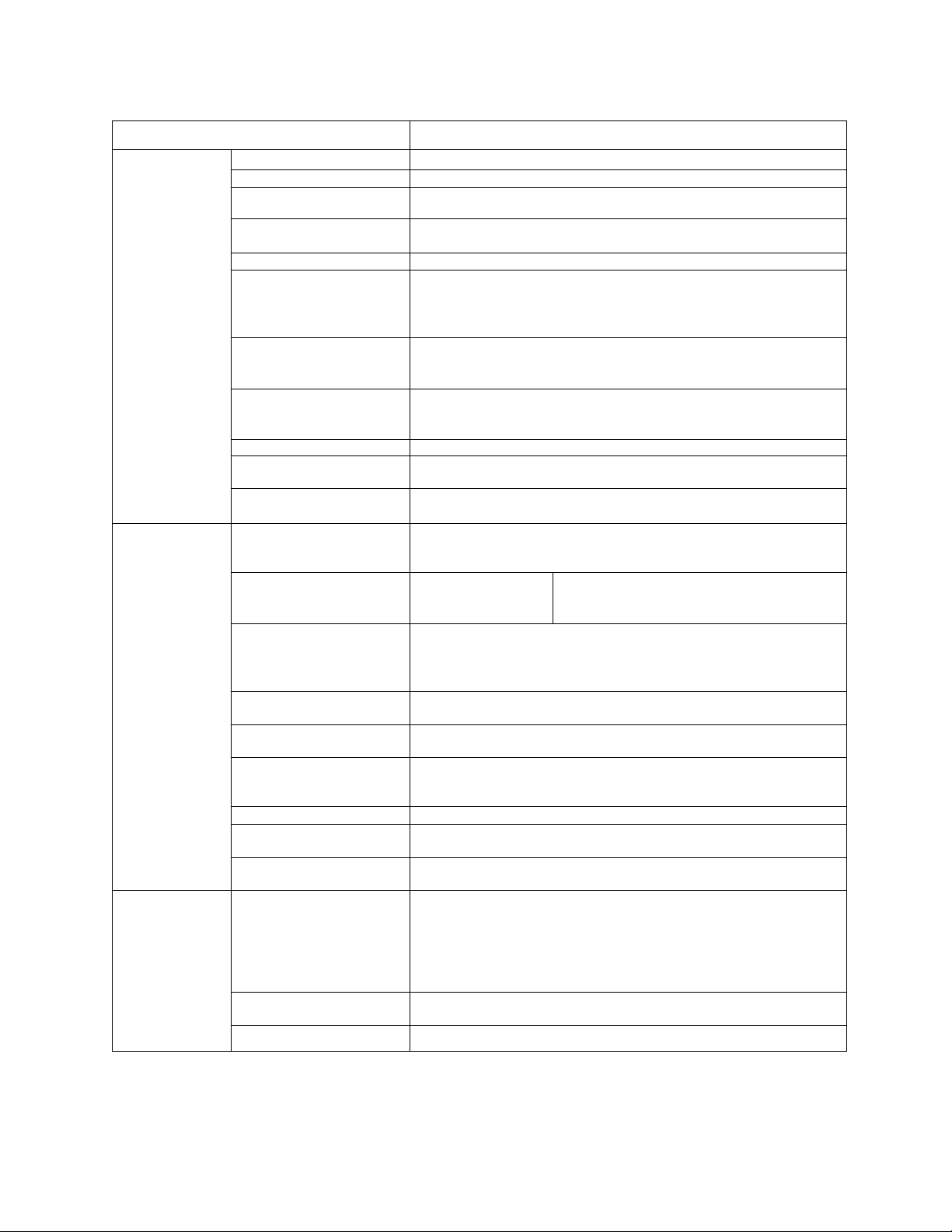
3.0 Standard Specifications (cont'd)
ITEM STANDARD SPECIFICATIONS
Control Control Method Sinusoidal PWM control
Output voltage regulation Same as power line.
Output frequency 0.0 to 160.0 Hz (0.0 to 60 Hz setting when shipped); maximum
frequencv ranqe is 30 to 160 Hz *1
Operating
functions
Protection
Frequency setting
resolution
Frequency accuracy ±0.5% (at 25°C; ±10°C) aqainst the maximum frequency
Voltage/frequency
characteristics
Frequency setting signals
Output frequency
characteristics of IV
terminal input signal
Frequency jump
Upper/lower limit
frequencies
PWM carrier frequency
switching
Acceleration/deceleration
time
Electrical braking
Forward or reverse run Forward run when F-CC closed; reverse run when R-CC closed;
Jogging run
Multispeed run By opening and closing different combinations of CC, SSI, SS2,
Automatic fault latch reset When a protective function is activated, the system checks main
Soft stall Sustains a run in overload mode (set at ON when shipped)
Automatic restart
Programmable RUN
patterns
Protective functions Stall prevention, current limit, overcurrent, overvoltage, short-
Electronic thermal
characteristics
Reset Resets inverter when N.O. contact is closed.
0.1Hz: Operating panel input; 0.03 Hz: Analog input; 0.01Hz:
Input throuqh computer interface (aqainst a 60 Hz)
Second-order nonlinear mode for variable torque.
"Max voltage" frequency adjustment (25 to 160 Hz), torque
boost adjustment (0 to 30 %), start-up frequency adjustment
(Oto 10 Hz)
3k ohms potentiometer (a 1 k to 10k ohms-rated potentiometer can
be connected). 0 to 10 Vdc (input impedance: 30k ohms), 0 to
5 Vdc (15k ohms), 4 to 20 mAdc (250 ohms)
Can be set to an arbitrary characteristic by setting 2 points.
3-point setting; setting jump frequency and band width
Upper limit frequency: 0.0 Hz to maximum frequency
Lower limit frequency: 0.0 Hz to upper limit frequency
Adjusted in the range of 5 kHz to 16 kHz (12 kHz setting when
shipped)
0.1 to 1200 seconds, switching of acceleration time 1 or 2,
selection of S-shaped 1 or 2, or selection of acceleration/
deceleration patterns
DC injection braking
reverse run when both F-CC and R-CC closed; coasting stop
when ST-CC open; emergency coast stop by a command from
operating panel
Jogging run engaged when N.O. contact is closed, (adjustment
range 0.0 to 20.0 Hz)
and SS3, the set speed or seven preset speeds can be selected.
circuit devices, and attempts the restart up to 5 times (activated
when shipped)
Smoothly recovers a normal run of a free-running motor utilizing
motor speed detection control.
Allows setting of 7 different patterns of automatic operation
circuit at load, load-end ground fault, undervoltage, momentary
power interrupt, electronic thermal overload, main circuit over
current at start-up, load-end overcurrent at start-up, cooling
fin overheat, and emergency stop. Provisions for external
fault signal.
Standard motor/constant torque V/f motor switching, and
electronic thermal stall prevention activating level adjustment
Start-up frequency adjustment (0 to 10 Hz),
braking voltage adjustment (0 to 20 %),
braking time adjustment (0 to 5 seconds)
Consult the factory for applications above 80 Hz.
3-2
Page 14
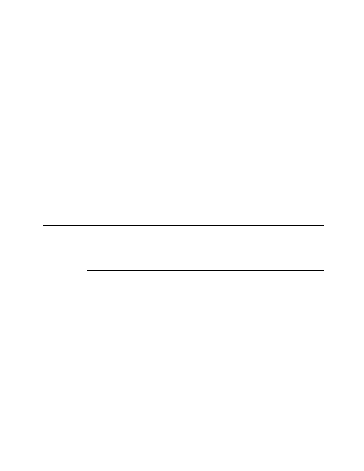
3.0 Standard Specifications (cont'd)
ITEM STANDARD SPECIFICATIONS
Display (4) 7-segment red LED
digits with colon and
decimal points
(4) discrete green LED's
(1) discrete red LED
(located inside enclosure)
Output signals Fault detection signal One form C contact (250 AC / 30 Vdc)
Low speed/reach signals Open collector output (24 Vdc, 50 mA maximum)
Upper limit/lower limit
frequency signals
Frequency meter output
and ammeter output
Enclosure type NEMAType 1 (standard)
Cooling method
Color Sherwin Williams Precision Tan #F63H12
Service
conditions
Service environment Indoor, altitude 1000m (3,300 ft) maximum. Must not be exposed
Ambient temperature From -10 to 40°C (contact Toshiba about operation above 40°C)
Relative humidity
Vibration
Output
frequency/
OFF
Warning
indications
Fault
indications
Data and
status
Speed
scaling
Data
storage
DC charge
indicator
Open collector output (24 Vdc, 50 mA maximum)
Ammeter rated at 1 mAdc at full scale, or voltmeter rated at
7.5 Vdc, 1 mA
Convection-cooled 02-2035 and 02-4055
Fan-cooled 02-2055 thru 02-2330 and 02-4080 thru Q2-420K
to direct sunlight, or subjected to corrosive or explosive gas
or mists.
95 % maximum (no condensation allowed)
Acceleration at 0.5 G maximum (20 to 50 Hz), amplitude at
0.1 mm maximum (50 to 100 Hz)
Frequency range 0.0 to 160 Hz and OFF state
Stall preventive warning, overvoltage limit
warning, overload warning, power-end undervoltage
warning, DC main circuit undervoltage warning,
setting errors, EEPROM abnormality, and data
transfer abnormality warnings
Overcurrent, overvoltage, load-end ground fault,
overload, armature overcurrent at start-up, load-end
overcurrent at start-up, heat sink overheat.
Inverter status (forward/reverse run, frequency set
value, output current, etc.) and each set value
An arbitrary unit (revolution speed, linear velocity or
the like) as well as output frequency can be displayed
by use of an arbitrary multiplication factor
A number is assigned to each inverter (for 0 to 31
inverters).
Main DC bus circuit capacitors charge indicator
TOSHIBA
3-3
Page 15
TOSHIBA
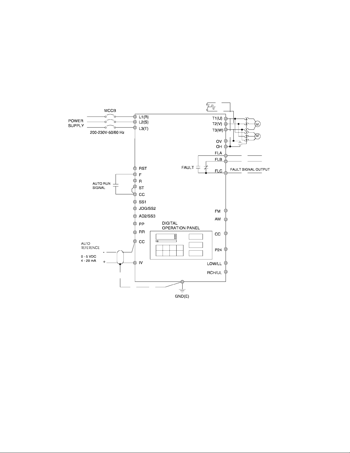
4.0 Wiring
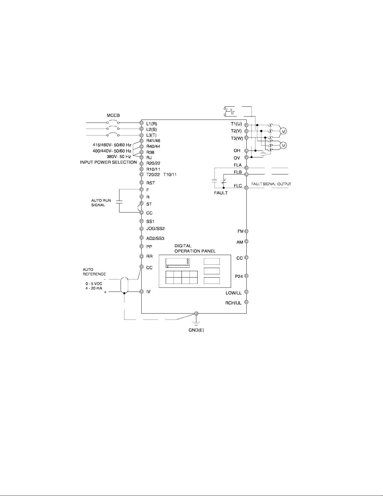
4.1 Simple Connection Diagrams
Q-FLOWSAVER II
STANDARD CONNECTION
MODEL 2035 TO 2330
Notes:
1) For control/driver terminal block layout see Page 5-5.
2) For recommended wire sizes see Page 4-3.
3) For terminal connections and functions see Page 5-6 through 5-8.
4) Contact Toshiba when interfacing with a process controller.
4 -1
Page 16
4.1 Simple Connection Diagrams (cont'd)
Q-FLOWSAVER II
STANDARD CONNECTION
MODEL 4055 TO 420K
POWER
SUPPLY
TOSHIBA
Notes:
1) For control/driver terminal block layout see Page 5-5.
2) For recommended wire sizes see Page 4-3.
3) For terminal connections and functions see Page 5-6 through 5-8.
4) Contact Toshiba when interfacing with a process controller.
4-2
Page 17

TOSHIBA
4.2 Selection of Main Circuit Wiring Equipment and Standard Cable Sizes
Inverter
Type form
•Molded case
circuit breaker
(MCCB)
Amp
rating
(A)
Q2-2035 20 13.8
Q2-2055 30 21.9
Q2-2080 50 31.6 #10
Q2-2110 70 40 #8
Q2-2160 90 60 #6
Q2-2220 100 78
Q2-2270 125 98 #3
Q2-2330 150 115
Q2-4055 15 10.9
Q2-4080 30 15.8
Q2-4110 30 20.1
Q2-4160 40
Q2-4220 50 38.8 #8
Ampacity
(FLA X 1.25) •'Typical cable size (AWG)
Main power
(A)
motor load
30.2
and
#14
#12
#4
#2
#14
#14
#12 #14
#10
230Vac and
460Vac control
power source
Frequency
command input,
frequency meter,
ammeter
3-core shield cable
(speed reference)
2-core shield cable
#20
Other
signal
circuits
#18
Q2-4270 70 48.8 #8
Q2-4330 90 57.5 #6
Q2-4400 100 74.8
Q2-4500 100
Q2-4600 125
Q2-4800 175 138 #1/0
Q2-410K
Q2-412K
Q2-415K
Q2-420K
200 178.3 #3/0
225 223 #4/0
300 268 ••• 2(#2/0)
350 330 ••• 2(#4/0)
93.4
110.7 #2
See next page for notes and precautions.
#4
#3
4-3
Page 18

4.2 Selection of Main Circuit Wiring Equipment and Standard Cable Sizes (cont'd)
* The customer supplied Molded Case Circuit Breaker (MCCB) or Magnetic Circuit
Protector (MCP) should be coordinated with the available short circuit current. The units
are rated for output short circuit faults of 5000A (1 - 50 HP), lO.OOOA (51 - 200 HP), and
18,000A (201 - 400 HP) according to the UL 508C "Power Conversion Equipment",
Table 58.2 or CSA Standard C22.2 No.14-M1987 "Industrial Control Equipment"
Table 24. The selection of breakers for this table is in accordance with 1990 NEC
Article 430. The selection of these breakers takes into consideration motor starting
at the low end of the output voltage specifications but does not consider the use of
high efficiency motors.
* For multiple motor applications, the magnetic only MCP should be replaced by a thermal
magnetic MCCB. The MCCB should be sized according to 1.25 X (largest motor Full
Load Amps) + (sum of all other motor Full Load Amps) to meet National Electric Code
(NEC) or Canadian Electrical Code (CEC) requirements. An individual overload relay
must be provided for each motor in multiple motor applications.
** Wire sizing is based upon NEC table 310-16 or CEC Table 2 using 75 deg C cable, an
ambient of 30deg C, cable runs for less than 200 FT., and copper wiring for not more
than three conductors in raceway or cable or earth (directly buried). The customer should
consult the NEC or CEC wire Tables for his own particular application and wire sizing.
TOSHIBA
** For cable runs greater than 200 FT. between the motor and inverter, consult the factory
before installing.
*** Use two parallel conductors instead of a single conductor (this will allow for the proper
wire bending radius within the cabinet). Use separate conduits for routing parallel
conductors. This prevents the need for conductor derating (see note 3 this page).
Use separate conduits for routing incoming power, power
CAUTION to motor, and control conductors. Use no more than three
K
Notes:
1. ) Auxiliary relays used to switch inverter signals should be capable of switching
low current signals (i.e. 5mA).
2. ) The inverter has internal overload protection, but the Local, National, or
Canadian Electrical Codes may require external motor overload protection.
3. ) When wiring with parallel conductors, the conductors should be kept together in
phase sets with U1, VI, W1 in one conduit and parallel conductors U2, V2, W2
in another conduit. The ground conductor should be in one of these conduits.
4) Twisted pair wiring should be used for external meters connected to AM and FM
terminals.
power conductors and a ground conductor per conduit.
4.3 Grounding
The inverter should be grounded in accordance with Article 250 of the National Electrical
Code or Section 10 of the Canadian Electrical Code, Part I and the grounding conductor
should be sized in accordance with NEC Table 250-95 or CEC, Part I Table 16.
!\ CAUTION Conduit is not a suitable ground for the inverter.
4-4
Page 19
TOSHIBA
5.0 PWB Layout, Jumpers, and Terminal Connections
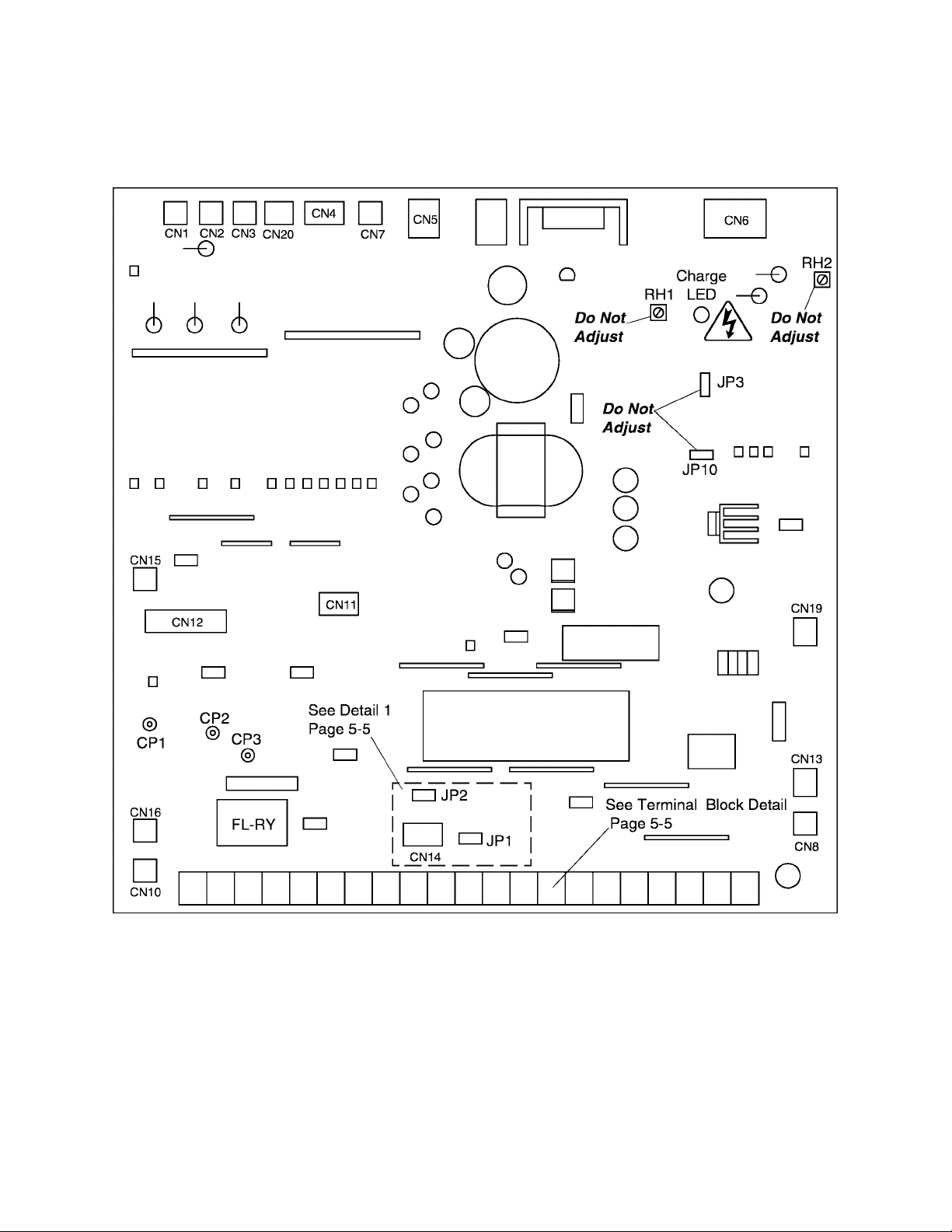
5.1 Control/Driver Board for Q2-2035 through Q2-2330
The following pictorial shows a layout of the major components located on the
control/dhver board VF3B-0100.
Note:
1) Potentiometer RH1 is used for control power supply stabilization. This adjustment is
factory set and any ADJUSTMENT BY THE USER SHOULD NOT BE ATTEMPTED.
2) Potentiometer RH2 is used for voltage detection level bias. This adjustment is factory
set and any ADJUSTMENT BY THE USER SHOULD NOT BE ATTEMPTED.
3) CPI, CP2,and CP3 are service testpoints.
4) Do not adjust JP3 and JP10.
5) Charge LED indicates charged capacitors. DO NOT TOUCH internal parts if lighted.
5-1
Page 20
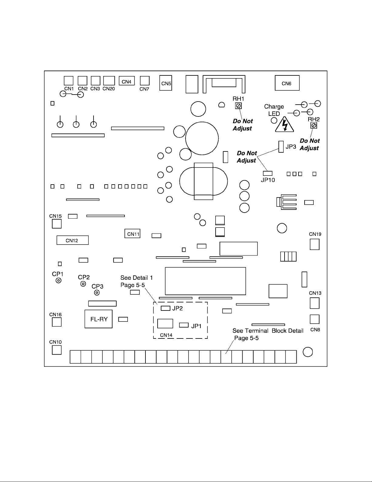
5.2 Control/Driver Board for Q2-4055 through Q2-4330
The following pictorial shows a layout of the major components located on the
control/dhver board VF3B-0101.
TOSHIBA
Note:
1) Potentiometer RH1 is used for control power supply stabilization. This adjustment is
factory set and any ADJUSTMENT BY THE USER SHOULD NOT BE ATTEMPTED.
2) Potentiometer RH2 is used for voltage detection level bias. This adjustment is factory
set and any ADJUSTMENT BY THE USER SHOULD NOT BE ATTEMPTED.
3) CP1, CP2, and CP3 are service testpoints.
4) Do not adjust JP3 and JP10.
5) Charge LED indicates charged capacitors. DO NOT TOUCH internal parts if lighted.
5-2
Page 21
TOSHIBA
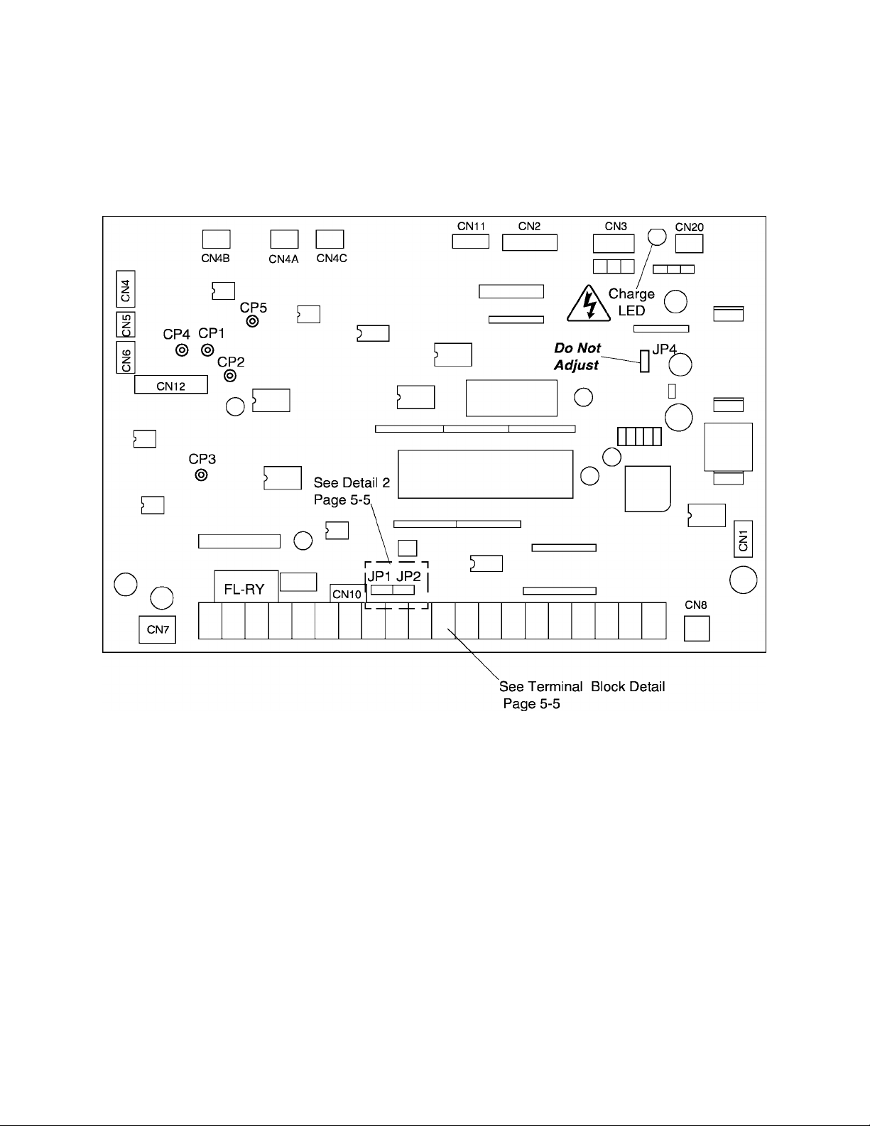
5.3 Control Board for Q2-4400 through Q2-420K
The following pictorial shows a layout of the major components located on the
control board VF3C-1200.
Note:
1) CPI, CP2, CP3, CP4, and CPS are service testpoints.
2) Do not adjust JP4.
3) Charge LED indicates charged capacitors. DO NOT TOUCH internal parts if lighted.
5-3
Page 22
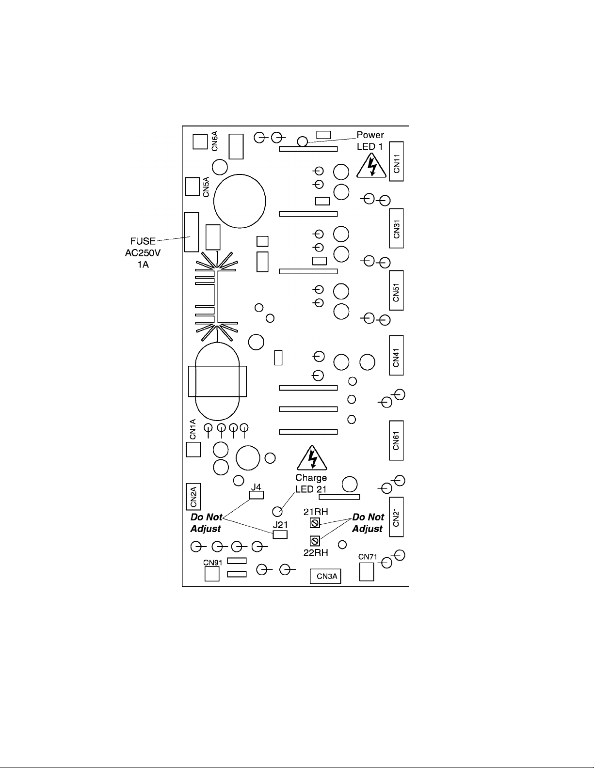
5.4 Driver Board for Q2-4400 through Q2-420K
The following pictorial shows a layout of the major components located on the
driver board 35589.
TOSHIBA
Note:
1) Potentiometer 21RH (OP) is the main circuit overvoltage detection trip set. This
adjustment is factory set and any ADJUSTMENT BY THE USER SHOULD NOT BE
ATTEMPTED.
2) Potentiometer 22RH (MUV) is the main circuit undervoltage detection trip set. This
adjustment is factory set and any ADJUSTMENT BY THE USER SHOULD NOT BE
ATTEMPTED.
3) Do not adjust J4 and J21.
5) Charge LED indicates charged capacitors. DO NOT TOUCH internal parts if lighted.
5-4
Page 23

TOSHIBA
5.5 Jumper Details
10V 5V
IQ OlO
The jumper connections for each of the printed wiring boards on Pages 5-1 through
5-3 are shown in the enlarged details below. Only jumpers JP1 and JP2 should be
adjusted by the user. See Page 5-6 for jumper adjustments.
JP2
o in ni
Detail 1 (Reference pages 5-1 and 5-2)
1 1
1 1
IV 1 1
1 1
1
I V 10V 5V
lO OlO OlO OI
IP1
Detail 2 (Reference page 5-3)
JP2
Note:
Jumper settings as shown in these illustrations are for reference purposes only and do
not necessarily reflect factory settings nor correct settings for a particular application.
5.6 Control/Driver Board Terminal Block Details
The control/driver board terminal block is shown in detail below. Each of the twenty-one
terminals is functionally labeled. See Pages 5-7 and 5-8 for a list of terminal functions.
Control/Driver Board Terminal Block Detail (Reference pages 5-1,5-2, and 5-3)
© © © © © © © © © © © © © © © © © © © © ©
FLA FLB FLC P24 RCH LOW FM AM PP RR IV CC ST F R CC SSI JOG AD2 RST CC
(UL) (LL) (SS2) (SS3)
5-5
Page 24
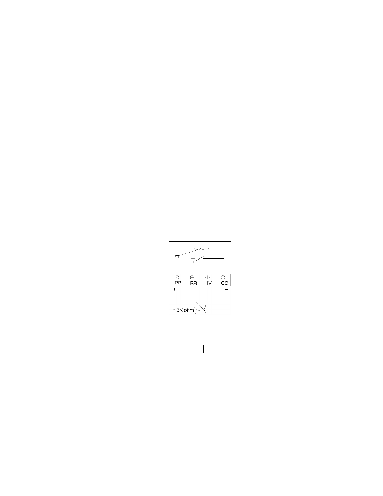
5.7 Jumper/Terminal Connections and Functions
The following table shows how jumpers JP1 and JP2 are set for use with the analog
input terminal connections RR and IV. Jumper numbers and settings which are shown in
this table are applicable to all printed wiring boards (see page 5-5 for terminal block
and jumper details).
Terminal/Jumper Connections for Input Reference Signals
TOSHIBA
JP1
i V
0 olo
I V
N/A
I V
JP2
10V 5V
I 'vJ I 'v.3
N/A
O
N/A
N/A
10V 5V
I 0.") 'vJ I 00
Terminal Connections
No external connections; JP1 and
JP2 should be set as shown for
keypad operation (normal factory
settinoV
_______________________
0
PP
0-20mA
(4-20mA)
PP
0
PP0RR0IV
15Koh
RR IV
RR IV
0-5Vdc
+
CC
0
CC
0
CC
0-1 OVdc
Use when not inputting any external
reference signals into terminal RR or
IV. P.PrG parameter #2 "priority of
RR terminal input" is N/A.
Use when inputting a 4(0)-20mA
external reference signal to terminal IV.
P.PrG parameter #2 "priority of RR
terminal input" should be set to 0 "on".
See page 7-5.
Use when inputting 0-5Vdc external
reference signal to terminal IV.
P.Prg parameter #2 " priority of RR
terminal input" should be set to 0 "on"
See page 7-5.
Use when inputting 0-1 OVdc external
reference signal to terminal RR.
—
P.Prg parameter #2 " priority of RR
terminal input" should be set to 1 "on".
See page 7-5.
Use when inputting 0-1 OVdc external
reference signal to terminal RR.
P.Prg parameter #2 " priority of RR
terminal input" should be set to 1 "on".
See page 7-5.
Function
10V 5V
0 ('<\ ('i
PP
+
o
SW
c
+
•
.
-r0
s.„
0 o
RR IV CC
f
r-
A
---
y'“
0-20mA
(4-20mA)
Use when inputting a 4(0)-20mA
external reference signal to terminal IV
and a 0-1 OVdc reference signal to
terminal RR.
P.PrG parameter #2 "priority of RR
terminal input" should be set to 1 "on".
Terminal RR will override "have priority
over" terminal IV when switch (SW) is
closed.
See page 7-5.
3K ohm pot divides voitage between terminal PP and CC return. Any pot value between 1K to 10K ohms
can be used but makes adjustment more sensitive.
5-6
Page 25

TOSHIBA
5.8 Terminal Connections and Functions
Terminal
name
LI, L2, L3
(R, S, T)
T1, T2, T3
(U, V, W)
OH
ov
FLA, FLB, FLC
P24
RCH(UL)
Terminal functions Terminal
Input power terminals. Connect to either a 3-phase 50Hz, 200Vac
power supply or to a 3-phase 60Hz, 200 to 230Vac power supply
for models Q2-2035 to Q2-2330.
Input power terminals. Connect to either a 3-phase 50HZ, 380Vac
power supply or to a 3-phase 60HZ, 400 to 460Vac power supply
for models Q2-4055 to Q2-420K.
Output load terminals. Connect these terminals to a 3-phase
induction motor of the proper voltage.
Input terminal for external fault signal.
This is the return terminal for OH.
Output terminals of form C contact changes state when a protective
function has been activated (250Vac - 2A).
Output terminal for unregulated 24Vdc power supply
(100mA maximum output current).
Output terminal (open collector). Provides an output signal ground
(50 mAdc max) when the upper limit frequency is reached, when an
acc/dec is complete, or when the output frequency is within a specified
range. The choice is determined by settings of the Output Terminal
Selection function (:0.tb).
location
Bus bar
or
power
terminal
block
A
Terminal
block
LOW(LL)
FM
AM
PP
RR
IV
CC
(one of three)
Output terminal (open collector). Provides an output signal ground
(50 mAdc max) when a preset low speed or a preset lower limit is
reached. The choice is determined by settings of the Output Terminal
Selection function (:0.tb).
Output terminal for an external analog frequency meter.
Use either an ammeter rated at 1 mAdc at full scale or a voltmeter
rated at 7.5Vdc at full scale.
Output terminal for an external analog ammeter.
Use either an ammeter rated at 1 mAdc at full scale or a voltmeter
rated at 7.5Vdc at full scale.
Regulated 10Vdc power supply to be used with terminal RR for
remote terminal input.
Analog input terminal for a 0 - 5Vdc (JP2 @ 5V) or 0 -10Vdc
(JP2 @ 10V) external reference signal. Also used for wiring a Ik - 10k
ohm (3k ohm recommended) potentiometer to allow for remote speed
control operation.
Analog input terminal for a 0 - 5Vdc (JP1
(JP1 @ I) external reference signal.
This is the common return for PP,RR, and IV terminals.
Do not connect to GND(E).
V) or 4 (0) - 20mAdc
Control
PWB
terminal
block
5-7
Page 26

5.8 Terminal Connections and Functions (cont'd)
TOSHIBA
Terminal
name
ST
CC
(one of three)
SSI
JOG(SS2)
AD2(SS3)
Terminal functions Terminal
location
Input terminal for run interlock. When ST is shorted to CC, the inverter
is ready to run. With ST-CC open the unit will not run and if opened
while running a coasting stop begins.
Input terminal for forward run. When F is shorted to CC, a forward
run starts. With F-CC open, the unit decelerates to a complete stop.
Input terminal for reverse run. When R is shorted to CC, a reverse run
starts. With R-CC open, the unit decelerates to a complete stop.
If terminals F-CC and R-CC are shorted simultaneously, a reverse
run occurs.
This is the common return for ST terminal.
Do not connect to GND(E).
Input terminal for multi-speed run frequencies. Depends on setting of
function [1 .tb], JOG/SS2 and AD2/SS3 terminals. (See Page 10-1)
Input terminal for jogging run or multi-speed run frequencies. Depends
on setting of function [l.tb], SSI, AD2(SS3) terminals. (See Page 10-1)
Input terminal for multispeed run frequencies. Depends on setting of
function [l.tb], SSI, JOG/SS2 terminals. (See Page 10-1)
Control
PWB
terminal
block
RST
CC
(one of three)
GND(E)
(three provided)
R41/46
R40/44 *
R38
RJ *
R20/22
R10/11 *
With RST-CC shorted, the inverter's protective function resets.
This is the common return for ST, F, R, SSI, JOG(SS2), AD2(SS3),
and RST terminals. S
The inverter earth ground terminal.
o not connect to GND(E).
Do not connect to common return terminal (CC).
Jumper to RJ when using 415V-50Hz/460V-60Hz incoming power.
Do not jumper to R40/44 or R38.
Jumper to RJ when using 400V-50Hz/440V-60Hz incoming power.
Do not jumper to R41/46 or R38.
Jumper to RJ when using 380V-50Hz incoming power.
Do not jumper to R41/46 or R40/44.
Common for input power selection. Jumper to either R41/46, R40/44,
or R38. Do not jumper to more than one terminal at a time.
Output power terminal. Supplies 1-phase 200V-50Hz or 1-phase
220V-60HZ @ 40VA maximum.
Output power terminal. Supplies 1-phase 100V-50Hz or 1-phase
110V-60HZ @ 40VA maximum.
Frame
screw or
lug
Terminal
block
A
T10/11 T20/22
Supplied only on the Q2-4055 through Q2-420K units.
Output power return terminal for either 1-phase 200V-50Hz/220V-60Hz
@ 40VA or 1-phase 100V-50Hz/110V-60Hz @ 40VA.
5-8
Page 27
TOSHIBA
6.0 Operating Panel
6.1 Operating Panel Layout
The operating panel enables the user to enable or disable the keypad, input commands
from the keypad, and monitor the inverter operation on the LED displays. The panel
consists of the keypad and LED displays. The illustration below shows the operating
panel layout. See the following section for a description of each key and function.
See page 6-3 for a functional description of the LED display.
O M AN UAL CON TRO L
CLEAR
A
RESET
OH z
O %
OS LO
PRG
RUN
MANUAL
OFF
READ
V
WRITE
SETUP STOP
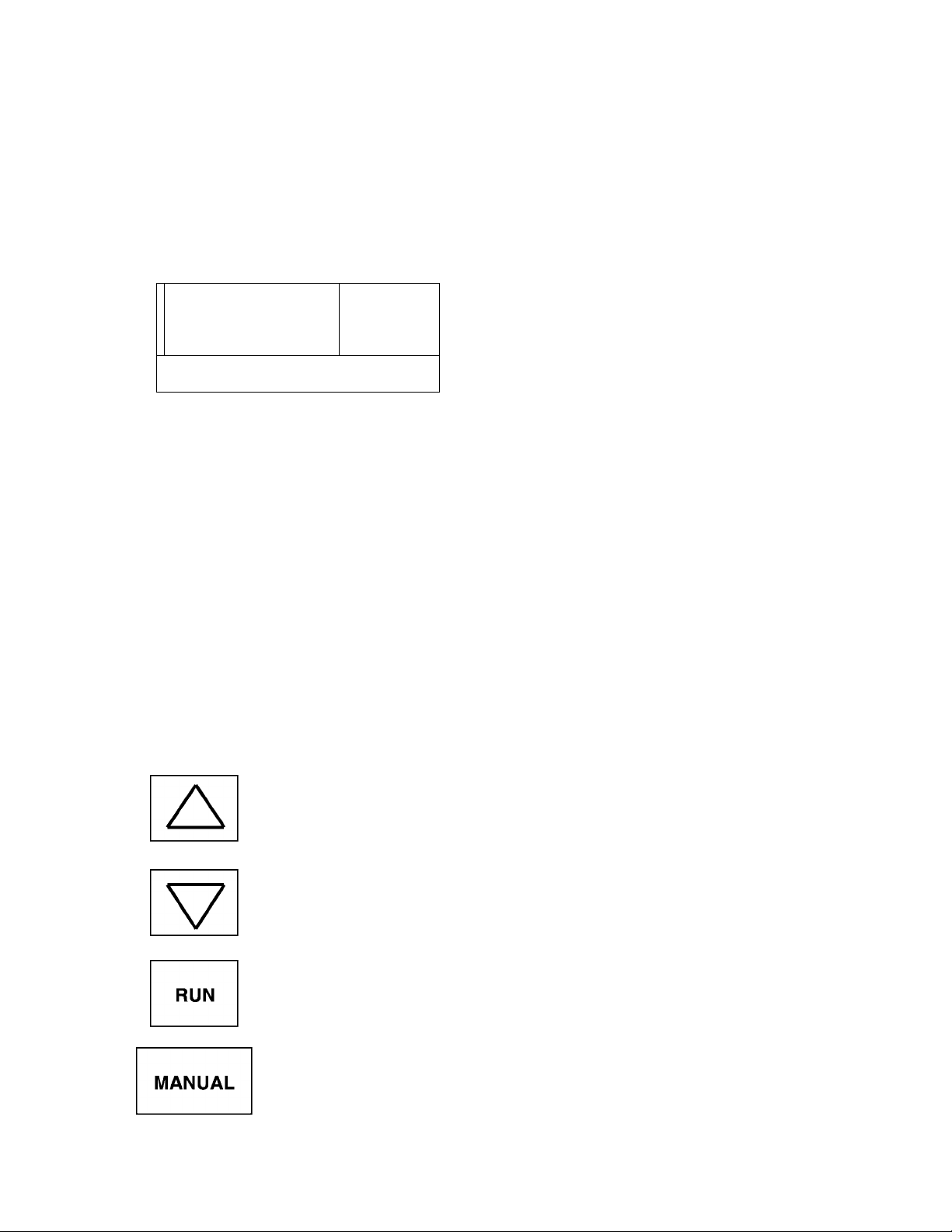
6.2 Operating Panel Keys and Functions
The following chart explains each of the key functions on the keypad
Keys and Functions
Key
Up scroll key used for increasing frequency or data values, scrolls parameter to
parameter, or upwards scaling of remote meters (FM, AM).
Down scroll key used for decreasing frequency or data values, scrolls parameter
to parameter, or downwards scaling of remote meters (FM, AM).
Used to start a normal forward/reverse run (only in manual mode), manual LED
will flash in run mode even at frequency = 0 Hz.
AUTO
Function
Key enables the manual control mode and allows commands to be entered from
either the keypad or a computer terminal. The Manual control LED is on when
operating in the manual control mode. When switching to auto mode, first press
"off" key; otherwise inverter must be at 0 Hz. If "auto" key is pressed while still
running in manual mode, an ":Err. 7" will flash.
6-1
Page 28
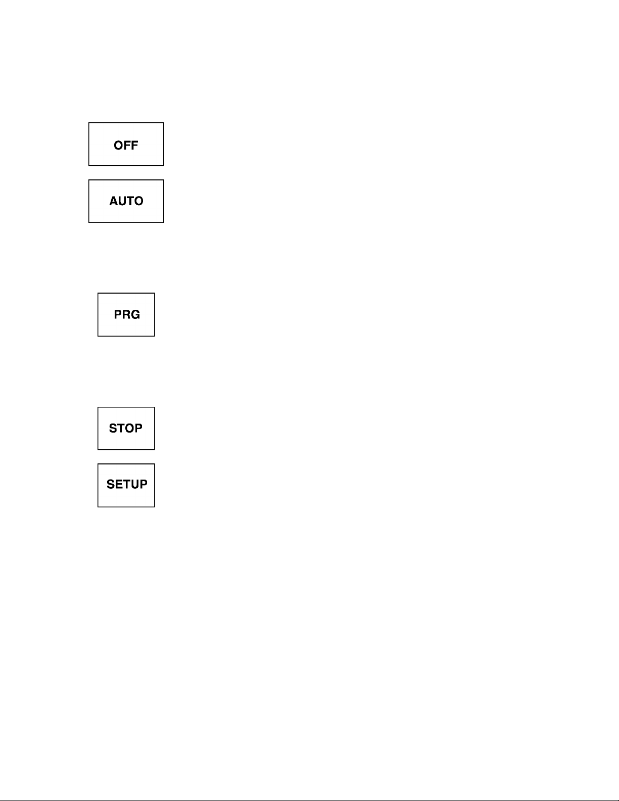
6.2 Operating Panel Keys and Functions (cont'd)
Keys and Functions
Key disables RUN or STOP commands until either the AUTO or MANUAL
key is pressed. Display reads "OFF". Motor coasts to a stop if key is pressed
while motor is running
Disables manual control and turns the manual control LED off; drive will accept
commands from terminal strip connector or computer input only.
This key is used to scroll through the system parameters (see page 7-2), read
READ
WRITE
data from within the group or setup parameters, write data changes into the
non-volatile memory. System status information is available while drive is
running.
Key used to scroll through the parameter groups and returns to frequency
setting if in any other mode.
TOSHIBA
CLEAR
RESET
When data changes have been made in error, this key will allow user to clear
data back to data = 0 (if allowed). Also resets trips, or returns to frequency
mode.
This key stops the drive in manual mode. The manual mode stop can be
programmed to coast or decelerate to a stop. Will cause the drive to trip and
coast in any other mode. Can be used as an emergency stop in any mode.
Allows access to setup parameters only and will automatically return to
frequency mode after all parameters have been stepped through.
6-2
Page 29
TOSHIBA
6.3 LED Display and Display Monitoring
The LED display provides the user with the operating frequency, function settings, and
status information necessary to easily monitor and set the operating parameters. The
individual LED's are identified and explained in the following chart.
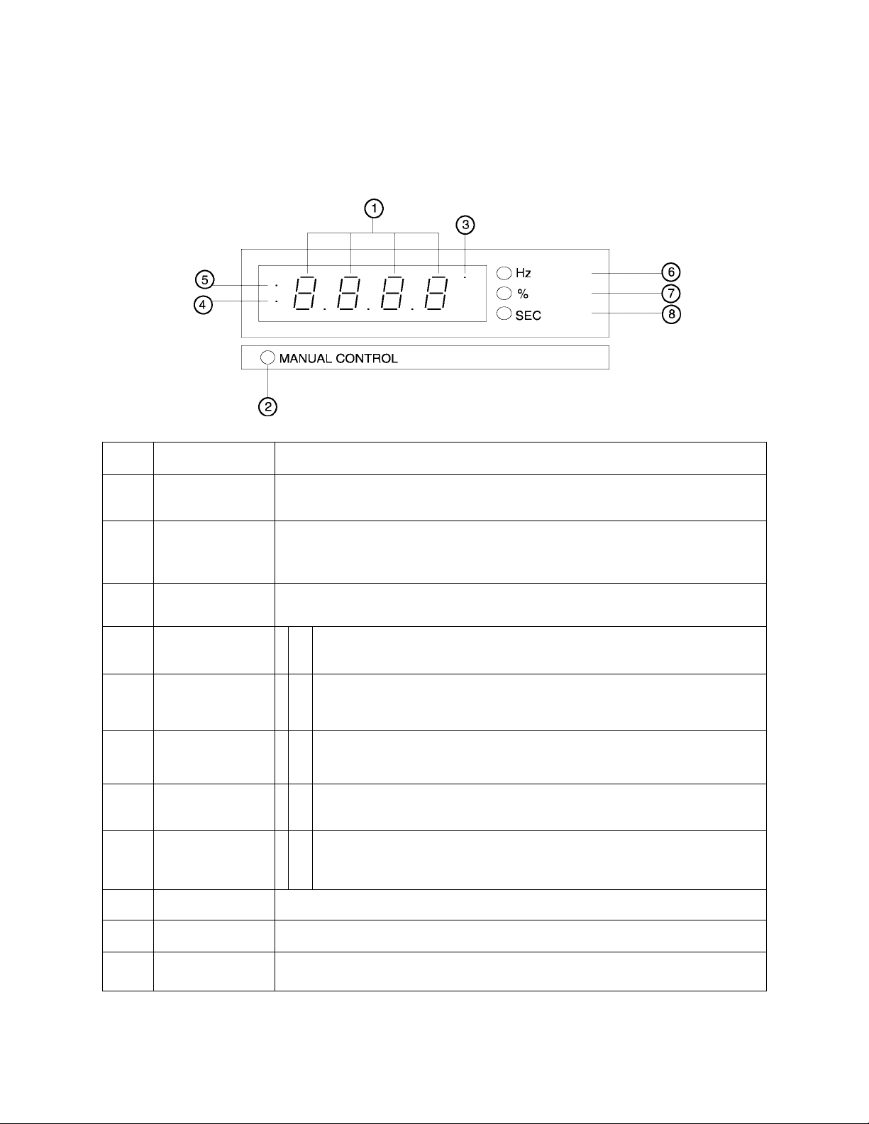
Display Monitoring
Item Name Function/status
o
©
©
©
©
Monitor display 7-segment, 4-column LED
Displays frequency, title, data, etc.
Panel control LED ON when the unit Is In the manual control mode
OFF when the unit Is In the auto (remote) control mode
FLASHING when the unit is in the manual control mode and the motor is running
Option mode LED ON when the computer interface option is enabled. (Contact Toshiba
for information.)
Both LED's are normally OFF when the monitor is displaying operating
Monitor display
o
frequency or scaled operating frequency from the display scaler.
o
'•
LED 5 is ON and LED 4 is OFF when unit is in a patterned run sequence.
o
Both LED's are ON when the unit is in the parameter setting mode using
the operating panel keypad and the motor is not running.
•
Both LED's are FLASHING when the unit is in the parameter setting mode
~0
using the operating panel keypad and the motor is running.
0
LED 4 is ON and LED 5 is OFF when the unit is in the parameter setting
o'
mode and the operating panel keypad is disabled.
•
(Computer Command Mode)
©
©
©
Hz display LED ON when the display is indicating frequency.
% display LED ON when the display is indicating a percentage.
Time display LED ON when displaying time in seconds.
6-3
Page 30

6.4 Display Alphanumerics
The 7 segment LED display is able to display all of the numerals but is unable to
properly form all of the characters of the alphabet. Therefore some characters of the
alphabet will appear as special symbols and others are not used at all. The tables
below show the numbers and characters that are used and how each appears on the
7 segment display.
TOSHIBA
Numerics LED display
0
1
2
3
4
5
6
7
8
9
/_/
l_
1 1
/_/
/_/
_l
n
/
/
~l
~l
1
l~
_f
l~
1
1
n
n
Characters LED display
A
b
C
d
E
F
G
H
1
1
J
L
M
n
1 1
1
u
r
l_
1
u
r
l_
r
1
r
u
1 1
1 1
1
1
1
u
1
l_
n
1 1
6-4
O
u
y
n
n
LI or U
P
r
S
t
V
-
n
1
r
1
1 1
u
LI
1 1
J
-
r
J
l_
Page 31

TOSHIBA
7.0 Parameter Groups
7.1 Definitions of Setup and Group Parameters
SETUP PARAMETERS
This parameter group is accessed by pressing the dedicated "SETUP" key on the
keypad. This parameter group should not be considered operationally any different
from other parameter groups. This group is assigned a dedicated key because of the
probable need to access It most often and because It contains the adjustable parameters
considered "fundamental" to drive operation and application. This includes parameters
such as acceleration and deceleration times, upper and lower frequency limits, bias and
gain, electronic thermal protection, and stall prevention activation.
USER GROUP PARAMETERS
This parameter group is accessible from the group parameter menu. The menu can be
scrolled by repeated pressing of the "PRG" key. This group contains features such as
assignment of a personal lockout code, options for the Volts per Hertz (V/F) ratios, reset
to factory settings, limiting maximum frequency, setup of automatic torque boost and
level, #2 acceleration and deceleration time and selection of patterns for #1 or #2.
COMMUNICATION GROUP PARAMETERS . l . r r u
This parameter group is accessible from the group parameter menu. The menu can be
scrolled by repeated pressing of the "PRG" key. This group contains features for setting
up the serial communication protocol, carrier frequency selection, input and output
terminal selection, and setting up the unit for power failure control and automatic
restarting.
JUMP FREQUENCY GROUP PARAMETERS . .
This parameter group is accessible from the group parameter menu. The menu can be
scrolled by repeated pressing of the "PRG" key. This group contains features for setting
three different operating patterns jump frequency and jump width. This group also
contains selections for PID control and adjustments.
DISPLAY GROUP PARAMETERS
This parameter group is accessible from the group parameter menu. The menu can be
scrolled by repeated pressing of the "PRG" key. This group contains features for setting
up low speed frequency detection and speed reach selection. It also contains settings
for DC braking.
■ I (
■ u .
L
LI .
I
LI
SPEED GROUP PARAMETERS
This parameter group is accessible from the group parameter menu. The menu can be
scrolled by repeated pressing of the "PRG" key. This group contains features for setting
multispeed run frequencies 1 - 6 and firespeed override frequency.
PATTERN FREQUENCY GROUP PARAMETERS
This parameter group is accessible from the group parameter menu. The menu can be
scrolled by repeated pressing of the "PRG" key. This group contains features for setting
pattern 1 - 7 forward or reverse and run time, number of cycles, jog frequency, jog stop
pattern selection, and setting of hysteresis.
In each of the above group parameters, some of the more important functions have been
mentioned. The following System Parameters Adjustment Range and Factory Setting
tables show all of the group parameters and each of the functions are shown in detail.
The ITEM NO. Is an Identifier used for reference only. It shows the correct numerical
order for each function. This is helpful when locating the function definition in Keypad
Operating Functions (See Section 9.0 page 9-1).
, I I
u
I I
7 -1
Page 32

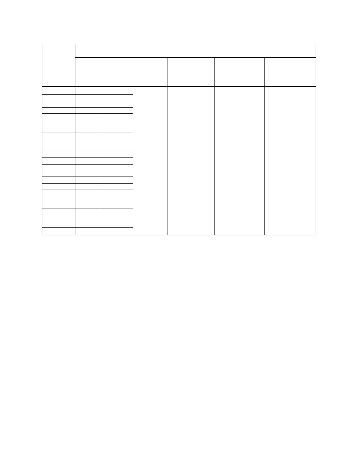
7.2 System Parameters Adjustment Range and Factory Settings
TOSHIBA
PARAMETER
DISPLAY
• I ( / 1 /
.I'LL 1
• 1 r r 1
• LI L L I
•III
• /_i L
• / /
• /_ L
• /~/ (
• 1 1
• r n 1
, / “ 1 1
• /~/ “(
• 1 L
• /“ n 1
. I II-
• 1 II
»1-111
• r 1 1
• _/ L L
• r r 1 II
• _/ L L 1
• M n r
. L' . 1 r LI
• /“ M
. r I I
• n L L
. n . L LI
• / (
• L LI
• / r 1
• LI 1 L
• 1 1 ( n
. L _( 1
• n r r 1
. 1 1 L L L
• 1 r r 1
• LI L L L
• n L 1
.1 L . 1
• n / “1
.1 L . L
•/“LI “1
• _l L L L
• n 1
• 1 L
• L L r r
. 1
_
1, L -1
• r 1 r
• L LI LI L
ITEM
NO.
PARAMETER
DESCRIPTION
ADJUSTMENT
RANGE
FACTORY
SETTING
REFERENCE
SETUP PARAMETERS *
1 Acceleration time #1
2 Deceleration time #1
3 Upper frequency limit
4
5
Lower frequency limit
Terminal IV point #1 setting signal
6 Point #1 output frequency
7
Terminal IV point #2 setting signal 0-100% 100% 9-1
8 Point #2 output frequency
0.1 - 1200 sec 90.0 sec 9-1
0.1 - 1200 sec 120.0 sec 9-1
0.0 Hz - FH
0.0 Hz - UL
60.0 Hz 9-1
0.0 Hz 9-1
0-100% 20% 9-1
0.0 Hz - FH
0.0 Hz - FH
0.0 Hz 9-1
60.0 Hz 9-1
9 Electronic thermal protection level 10-100% 100% 9-1
10
11
Stall prevention activation level
10-120% 120% 9-1
Electronic thermal protection select 0: STD-motor, no soft stall
0
1: STD-motor, soft stall
2: VF-motor, no soft stall
3: VF-motot, soft stall
USER GROUP PARAMETERS **
1
2
Maximum frequency 30 - 160 Hz 60 Hz 9-3
Automatic torque boost 0: Off
0 9-3
1: On
3 Torque boost 0 - 30 % 3% 9-3
4
5
Base frequency of maximum voltage level 25 - 160 Hz 60 Hz 9-3
Standard setting mode selection
0: Factory settings
0 9-3
1: 50 Hz motor
2: 60 Hz motor
3: Reset to factory settings
6
7 Deceleration time # 2
8 Pattern of ACC/DEC #1
Acceleration time #2
0.1 - 1200 sec 10.0 sec 9-3
0.1 - 1200 sec 10.0 sec 9-3
0: Linear
0 9-3
1: S-curve
2: C-curve
9 Pattern of ACC/DEC #2
0: Linear
1 9-4
1: S-Curve
2: C-Curve
10 Selection to use ACC/DEC #1 or #2 0: Acc/Dec #1
0
1: Acc/Dec #2
11 V/F pattern
0: Constant torque
1 9-4
1: Variable torque
12
Timed stop/coast to stop selection
0: Deceleration stop
0
1: Coast to stop
13 Personal lock out code 0 - 255 0
PAGE
9-2
9-4
9-4
9-4
7-2
Page 33

TOSHIBA
7.2 System Parameters Adjustment Range and Factory Settings (cont'd)
PARAMETER
DISPLAY
• r n r
. L . 1 r LI
• n r 1
•III _l L
• _ L (1
. / LI 1
• n r r
• 1 / . L
• 1 r /
, L / . L L
• ( / /
• i . L LI
• ri 1 1
• IJ*L M 6 Output terminal selection
• n n L
• LI 1 L
• ( _ _
• ( . M LI .
• / n 1
, IJ.I II L
ITEM
NO.
1
Automatic restart after Instantaneous power
2
3
Power failure function selection
(This function valid on 230 volt units only)
4 Fault trip data retention selection
5 Input terminal selection 0: SS2, SS3
7
Option card multi-functional selections 0: Off
8
9 Baud rate (RS232/RS485) 0: 150/1200
PARAMETER
DESCRIPTION
COMMUNICATION GROUP PARAMETERS **
failure selection
Automatic reset selection 0: Off
Inverter number
ADJUSTMENT
RANGE
0: Off
1: On
1: On
0: Off
1: On
0: Cleared
1: Saved
1: JOG, SS3
2: SS2, AD2
3: JOG, AD2
0: LL, UL
1: LOW, UL
2: LL, RCH
3: LOW, RCH
1: 12 bit binary absolute
input
2: 12 bit binary relativity
input
3: 3 number BCD input
4: 3 number BCD input
5: Pulse frequency
reference incut
6: Multi-speed input
7: Selection 1 with write
signal
8: Selection 2 with write
signal
9: Selection 3 with write
signal
10:Selection 4 with write
signal
11 :Selection 5 with write
signal
12:Selection 6 with write
signal
0-31 0 9-6
1: 300/2400
2: 600/4800
3: 1200/9600
4: 2400/19200
FACTORY
SETTING
1
1
0 9-6
0 9-6
0 9-6
3 9-6
0 9-6
0 9-6
REFERENCE
PAGE
9-5
9-5
• r LI/
• L , LI 1 L
• r L n
. _/ L , 1 1
• r r
• L 1
10
Communication data bits
0: 7 bits
1: 8 bits
11 Communication parity check and stop bit 0: Even
1: Even
2: N/A
3: N/A
4: Odd
5: Odd
12 PWM carrier frequency
7-3
5 - 16 kHz
0 9-6
0 9-6
12 kHz
9-6
Page 34

7.2 System Parameters Adjustment Range and Factory Settings (cont'd)
PARAMETER
DISPLAY
• 1 n r
. LI • ' 1 l-l
• r II
, I LI 1
• I r II
• LI 1 LI '
• r 11
• ' LI L
• I r 1 “1
• LI 1 U L
• r 1 J
, r LI
• ( r 11
, LI 1 LI J
• L L M 1
.1 LI. r 1
• (1
• LI 1
• r 1
• LI >
• (1
• LI M
• r r r
• LI 1 J
• 1 (1
.(-/.( 1 LI
• J r n 1
. LI J 1 . L
ITEM
NO.
PARAMETER
DESCRIPTION
ADJUSTMENT
RANGE
FACTORY
SETTING
JUMP FREQUENCY GROUP PARAMETERS **
1 Jump frequency #1 0.0 Hz - FH 0.0 Hz 9-7
2 Jump width #1 0.0 Hz - FH 0.0 Hz 9-7
3 Jump frequency #2 0.0 Hz - FH 0.0 Hz 9-7
4 Jump width #2 0.0 Hz - FH 0.0 Hz 9-7
5 Jump frequency #3 0.0 Hz - FH 0.0 Hz 9-7
6 Jump width #3 0.0 Hz - FH 0.0 Hz 9-7
7 PID setpoint control select 0: Off
1: On
8 Proportional gain 0 - 9999 1000 9-7
9 Integral gain 0 - 9999 500 9-7
10 Differential gain 0 - 255 0 9-7
11 Lag time constant 0 - 255 255 9-7
DISPLAY GROUP PARAMETERS **
1 Universal unit multiplication factor 0.00 - 200.0
(0.00 = OFF)
0 9-7
0.00 9-8
TOSHIBA
REFERENCE
PAGE
• 1 r
• L r
• r 1 I
,1 L M
2 Low speed detection 0.0 Hz - FH 0.5 Hz 9-8
3 Speed reach selection 0: Complete ACC/DEC
1 9-8
1: Frequency reach
reference
• r M
.1 1 L M 4 Speed reach detection range 0.0 Hz - FH 2.5 Hz 9-8
• r r 1 1
• 1 / L M
• 1 1 r
• LI LI I
• 11/
, LI LI L
• III
, LI IJ L
• ll nil /
• r.lj LI L
• ll n (“ /“
• Ll 1 J, J
5 Speed reach reference 0.0 Hz - FH 60.0 Hz 9-8
6 DC injection voltage start frequency 0.0 Hz - 10.0 Hz 0.0 Hz 9-8
7 DC injection voltage 0 - 20 % 0 % 9-8
8 DC injection time 0.0 - 5.0 sec 0.0 sec 9-8
9 Output voltage regulation 0 - 100 % 100 % 9-8
10 Overvoltage stall protection select 0: On
0 9-8
1: Off
• r ri /“
.1.1 1 Ll
• r r 1 1 r
. L , L II IJ
1 AC line/inverter transfer signal 0: Off
SPEED GROUP PARAMETERS **
0 9-9
1: On
• r 1
.-If I
• r 1
. -1 I L
• L _ 1
. -1 ' 1
• r II
.-If 1
• r r
.-If -f
• r r
. -1 1 Ll
• r r r
. 1 -f Ll 1
2 Multispeed run frequency #1 LL - UL 0.0 Hz 9-9
3 Multispeed run frequency #2 LL - UL 0.0 Hz 9-9
4 Multispeed run frequency #3 LL - UL 0.0 Hz 9-9
5 Multispeed run frequency #4 LL - UL 0.0 Hz 9-9
6 Multispeed run frequency #5 LL - UL 0.0 Hz 9-9
7 Multispeed run frequency #6 LL - UL 0.0 Hz 9-9
8 Firespeed override frequency (Sr7) LL - UL 0.0 Hz 9-9
7-4
Page 35

TOSHIBA
7.2 System Parameters Adjustment Range and Factory Settings (cont'd)
PARAMETER ITEM PARAMETER ADJUSTMENT FACTORY REFERENCE
DISPLAY
• n n r
•1*1 I IJ
• r
• r r
• ' ' '
• ri r r /
• I • / 1 f
• ("1 / 1
. L , L
• l"l L
• / L . M
• l"l L 1 L
. / . 1 L
• ("1 / 1
. r 1 ,1
• (“1 1 11
. r L.LL
• n L J
•111 11
.1 L.JL
• n L J
• ( 1 L I ( L
. i L . -( L
• (“1 L 1 1
• J 1 • 1
• (“1 1 r 1
. r L.JL
• n L r
• J 1 • 1
• n 1 rl
• 1 1-0 LIL
• 0 L L
•111 11
0 1 1-0 1 L
• 0 L J
NO.
1 Forward/Reverse rotation select 0 Reverse 1 9-10
2 Priority of RR terminal input 0 IV terminal input "on" 0 9-10
3 Mode for pattern run *** 0 Off 0 9-10
4 Time unit for pattern run time seiect *** 0 Seconds 0 9-10
5 Quantity of pattern run cycles *** 0 - 255 0 9-10
6 Pattern #1 run time *** 0 - 8000 0 9-10
7 Pattern #1 drive characteristics *** 0 Fwd run #1 Acc/Dec 0 9-10
8 Pattern #2 run time *** 0 - 8000 0 9-10
9 Pattern #2 drive characteristics *** 0 Fwd run #1 Acc/Dec 0 9-10
10 Pattern #3 run time *** 0 - 8000 0 9-10
11
12 Pattern #4 run time ***
13 Pattern #4 drive characteristics *** 0 Fwd run #1 Acc/Dec 0 9-10
14 Pattern #5 run time ***
15 Pattern #5 drive characteristics *** 0 Fwd run #1 Acc/Dec 0 9-10
Pattern #3 drive characteristics *** 0 Fwd run #1 Acc/Dec 0 9-10
16
17
18
19 Pattern #7 drive characteristics *** 0 Fwd run #1 Acc/Dec 0 9-11
Pattern #6 drive characteristics *** 0 Fwd run #1 Acc/Dec 0 9-11
DESCRIPTION RANGE
PATTERN FREQUENCY GROUP PARAMETERS
1 Forward
1 RR terminal input "on"
1 Terminal
2 Computer
1 Minutes
1 Fwd run #2 Acc/Dec
2 Rev run #1 Acc/Dec
3 Rev run #2 Acc/Dec
1 Fwd run #2 Acc/Dec
2 Rev run #1 Acc/Dec
3 Rev run #2 Acc/Dec
1
Fwd run #2 Acc/Dec
2 Rev run #1 Acc/Dec
Rev run #2 Acc/Dec
3
1
Fwd run #2 Acc/Dec
2 Rev run #1 Acc/Dec
Rev run #2 Acc/Dec
3
1
Fwd run #2 Acc/Dec
2 Rev run #1 Acc/Dec
Rev run #2 Acc/Dec
3
Pattern #6 run time ***
1
Fwd run #2 Acc/Dec
2 Rev run #1 Acc/Dec
Rev run #2 Acc/Dec
3
Pattern #7 run time ***
1
Fwd run #2 Acc/Dec
2 Rev run #1 Acc/Dec
Rev run #2 Acc/Dec
3
SETTING
**
0 - 8000 0 9-10
0 - 8000 0 9-10
0 - 8000 0 9-11
0 - 8000 0 9-11
PAGE
7-5
Page 36

7.2 System Parameters Adjustment Range and Factory Settings (cont'd)
PARAMETER
DISPLAY
• n n r
. r . 1 r U
• 1 n r
• U U LI
• 1 r 1 n
• LI. _/L 1
• r r /
. ' ~ -1 L
• r
, I ,/ IJ 1 1
• r L' U r
. ' ' J J
ITEM
NO.
20 Jog frequency 0.0 - 20.0 Hz 5.0 Hz 9-11
21 Jog stop select 0: Deceleration stop
22 Start-up frequency 0.0 - 10.0 Hz 0.0 Hz 9-11
23 Run frequency 0.0 Hz - FH 0.0 Hz 9-11
24 Run frequency hysteresis 0.0 Hz - FH 0.0 Hz 9-12
PARAMETER
DESCRIPTION
PATTERN FREQUENCY GROUP PARAMETERS (cont'd) **
ADJUSTMENT
RANGE
1: Coast to stop
2: DC Injection stop
FACTORY
SETTING
0 9-11
Parameters are alternately exhibited from setup menu by alternately pressing SETUP
key. Value of parameter can be read by pressing READ/WRITE key. Value can be
changed by continued pressing of "up" or "down" key. When desired value is reached
press the READ/WRITE key to store new value.
TOSHIBA
REFERENCE
PAGE
Group parameters are exhibited from group parameter menu by pressing PRG key.
When the desired group parameter is reached, individual parameters within the group
can be exhibited by alternately pressing the "up" or "down" key. Value of exhibited
parameter can be read by pressing READ/WRITE key.
Value of exhibited parameter
can be changed by continued pressing of "up" or "down" key. When desired value is
reached press the READ/WRITE key to store new value.
When P.SEL (mode for pattern run) is set to 0; pattern run times (Pt.It through Pt.7t)
and pattern run selections (Pt.1 through Pt.7) will be skipped when scrolling through
the Pattern Frequency Group Parameters.
7-6
Page 37

TOSHIBA
8.0 System Status Monitoring
The inverter operates with varying levels of supply voltage and current. A variable output
frequency of voltage and current is generated to drive the motor load. These input and output
levels of operating voltage and current are continually monitored by the inverter. It also monitors
for over temperature, input and output terminal settings, and condition of the microprocessor
with associated memory elements. These operating settings and variables have a certain value
or "status" associated with them and are used for inverter operation. They can also be monitored
by the operator to show the setup and conditions existing at any time. Three types of status
monitoring are used and explained below.
8.1 Normal Status Monitoring
Normal status monitoring occurs during normal operation. The ST-CC terminal must be
closed to run. The following table shows applicable keys, display, and status conditions
for normal status monitoring. The display values are for factory settings where no trips
or errors occurred. The display will change only if a new value is programmed into the
associated group adjustment range or if trips or errors have occurred. Scrolling occurs
by repeatedly pressing the READ/WRITE key after output frequency is displayed. Trips
or errors that have occurred (up to a total of three), will be displayed in order immediately
after the keypad software version display.
Key Display Status Condition
OFF
AUTO
MAN
RUN
STOP
RD/WRT
RD/WRT
RD/WRT
RD/WRT
I I L L
U I I
I I I I
u. u
I I I I
u. u
[Output Frequency]
/ or /
i_ I I II
u u
•
u
I I
u
Inverter is in the off position when ":OFF" is flashing.
Inverter is ready to run from terminal or computer interface.
Inverter is ready to run from keypad and manual control LED
is on.
Displays inverter's output frequency.
Emergency stop executed from keypad while in an automatic
run or while in remote control mode when "E" is flashing.
Indicates a forward (F) or reverse (r) run. If not running,
the display refers to the direction the unit would run.
Displays the frequency which the inverter is set to output
when running (60 FIz is factory setting).
Displays the percentage of the inverter's rated output current
when running (displays "0" when not running).
Displays the percentage of the inverter's rated output voltage
when running (displays "3" when not running).
RD/WRT
RD/WRT
RD/WRT
RD/WRT
RD/WRT
RD/WRT
I u n
I - I u
II III
u - u I
/_ _i
LI .-I.-I
• Ul_ II
.U.i -i.u
’
u
I I .I 1.1- I I
[Output Frequency]
Displays input terminal status code. See page 8-4
Displays output terminal status code. See page 8-5
Displays inverter's software version.
Displays keypad's software version.
Displays 4th error (no error occurred).
Returns to the original display of output frequency.
8-1
Page 38

8.2 Automatic Status Monitoring
Automatic status monitoring displays abnormal status conditions that can occur during
normal inverter operation. These conditions will cause warnings and error messages
to be displayed but will not cause the inverter to trip. The table below shows these
abnormal conditions and the associated display that will appear. These displays usually
appear during the time that the abnormal condition is occurring and will go away when it
is corrected. The abnormal condition should be corrected as soon as possible.
TOSHIBA
Key Display
r L
_( L
U I I i_ i_
I U I I
I I I I L L
I I U I I
I_ [Output Frequency]
p [Output Frequency]
)_ [Output Frequency]
I-
L I I . I
L
I- I I . I
O P P n
__
/
____
I
Status Condition
ST-CC terminal connector is open (must be connected to run).
The main AC supply power is low.
The inverter's DC bus voltage is low.
Stall prevention is activated when flashing "C" appears in
front of output frequency.
Overvoltage limitation is activated when flashing "P" appears
in front of output frequency.
Overload detection is activated when flashing "L" appears in
front of output frequency.
This error occurs while trying to switch from manual to
automatic mode or automatic mode to manual while inverter
is outputting a frequency.
This is a frequency setting signal error. Points 1 and 2 of a
frequency setting signal are to close together. Correct the
setting of points 1 and 2 by providing an adequate distance
between them.
r I I
r r r. u
r I I
crr.i-i
This error can be seen when attempting to set any of the
parameters with incorrect data values.
This error can be seen when attempting to set any of the
parameters with incorrect data values.
8-2
Page 39

TOSHIBA
8.3 Tripped Status Monitoring
Tripped status monitoring displays abnormal status conditions that can occur during
normal inverter operation. The table below shows these abnormal conditions which will
cause the inverter to trip "off" (stop normal operations). They are usually caused by
excessive power dissipation in either the inverter or motor, or by other circuit
abnormalities. A tripped status monitoring display usually appears during the time that
the abnormal condition is occurring and then remains on the display after the inverter
trips off. The inverter will remain off and the tripped status will remain displayed until the
inverter is attended to (reset) by the operator. Most conditions, which cause the inverter
to trip, occur very rapidly and the operator usually will not be aware that the trip
conditions are in process until the inverter has stopped. Each of the trip statuses are
automatically recorded in the non-volatile EEPROM memory of the inverter. An ordered
semi-permanent record of each trip (up to four) is created and can be viewed during the
normal status monitoring "scroll". These recorded trips are viewed immediately after the
keypad's software version, in the order that they occurred, as the READ/WRITE key is
pressed. These trips remain in the memory until replaced by new trips.
Key Display
n r I
U
L
Ill _/
u i_ i_
Ill _i
U
L _/
I l l u
U
L / (
n r I
U
L L
I I u
U I
/_
I I u
U I
n I
U
L
n u
U I I
L L
L
I
- I I .1-
- I I .-I
I I . I
Status Condition
I
Overcurrent occurred during an acceleration.
Overcurrent occurred during a deceleration.
Overcurrent occurred during a run.
Overcurrent detected at start-up (suspect inverter damage).
Overcurrent detected at start-up (suspect load short circuit).
_/
Overvoltage generated during deceleration.
Overvoltage from power supply.
Overload of motor occurred.
Overheat of inverter body or external fault occurred.
Ground fault overcurrent occurred in the load circuit.
Main RAM in main CPU is abnormal.
Main ROM in main CPU is abnormal.
u
RAM in operating panel CPU is abnormal.
I I .u
I I .1-1
L
LI
L
I
L
U -I
L
I I-
L
LI -I
L I -I
I / . L
ROM in operating panel CPU is abnormal.
Key in the operating panel keypad defective.
EEPROM data abnormality.
EEPROM trip data abnormality.
EEPROM setting data abnormality.
Communication data link abnormality.
These faults can be programmed to automatically restart
8-3
Page 40

8.4 Input Terminal Status Code
The table below shows the status codes when contact closures are placed across the
input terminals. JOG(SS2) and AD2(SS3) are multi-functional terminals. The correct
terminal input representation is determined by setting the Input Selection function [:l.tb].
Refer to Item 5 on page 7-3 and Terminal Block details on page 5-5. A reading such as
the example below indicates that terminal ST-CC has a closed contact across it. If input
terminal select [:l.tb]=3 then terminal JOG(SS2)=JOG, terminal AD2(SS3)=AD2, and
they are both open contact.
uII I
TOSHIBA
u
Display RR-CC ST-CC F-CC R-CC
i~i
l_
1 1
1
/_/
1 1
/_/
/
/
~l
~i
1
i~
_i
n
1
n
l~l
n
1
r
l_
1
LI
r
l_
r
1
OFF OFF OFF OFF
OFF OFF OFF ON
OFF OFF ON OFF
OFF OFF ON ON
OFF ON OFF OFF
OFF ON OFF ON
OFF ON ON OFF
OFF ON ON ON
ON OFF OFF OFF
ON OFF OFF ON
ON OFF ON OFF
ON OFF ON ON
ON ON OFF OFF
ON ON OFF ON
ON ON ON OFF
ON ON ON ON
Display SS1-CC JOG-CC
(SS2)
l_
1 1
1
/_/
n
1 1
1
/_/
1
l~l
/
/
~l
~i
1
i~
_i
L
1
n
l~l
r
l_
1
LI
r
L
r
OFF OFF OFF OFF
OFF OFF OFF ON
OFF OFF ON OFF
OFF OFF ON ON
OFF ON OFF OFF
OFF ON OFF ON
OFF ON ON OFF
OFF ON ON ON
ON OFF OFF OFF
ON OFF OFF ON
ON OFF ON OFF
ON OFF ON ON
ON ON OFF OFF
ON ON OFF ON
ON ON ON OFF
ON ON ON ON
AD2-CC
(SS3)
RST-CC
ON: Implies a closed contact or short between terminals.
OFF: Implies an open contact or no connection between terminals.
Terminal
Connections
RR-CC
ST-CC
F-CC
R-CC
Inverter's Status when terminal connections are closed (ON).
(See reference signal terminal connections on page 5-6).
RUN ENABLED {Must be connected to run)
FORWARD RUN ENABLED
REVERSE RUN ENABLED
If both F-CC and R-CC are on then a REVERSE RUN IS ENABLED.
551- CC MULTI-SPEED RUN ENABLED
552- CC MULTI-SPEED RUN OR JOG RUN ENABLED (Dependent upon SS2's usage)
553- CC MULTI-SPEED RUN OR ACC/DEC 2 ENABLED (Dependent upon SS3's usage)
RST-CC RESET MODE ENABLED (Reset occurs after momentary contact closure)
Page 41

TOSHIBA
8.5 Output Terminal Status Code
The table below shows the status codes of the open collector transistor outputs.
RCH(UL) and LOW(LL) are multi-functional terminals. The correct terminal output
representation is determined by setting the Output Selection function [:0.tb]. Refer to
Item 6 on page 7-3 and Terminal Block details on page 5-5. If output terminal select
[:0.tb]=2 then terminal RCH(UL)=RCH and terminal LOW(LL)=LL. A reading such as
the example below indicates that terminals RCH and LL are "on" (collector shorted to
ground).
RCH: Output frequency is within the set reach frequency range or acc/dec is complete.
LOW: Output frequency is equal to or greater than low speed frequency.
UL: Output frequency has reached the upper limit frequency (UL).
LL: Output frequency is equal to or greater than the lower limit frequency (LL).
8-5
Page 42

9.0 Keypad Operating Functions
This section discusses keypad operating functions. All of the functions that can be accessed
through the keypad, are discussed. The functions are listed and discussed in the order in which
they are accessed. The item number identifier following the function is used for ease of location
in the System Parameters Adjustment Range and Factory Settings (see section 7.2).
9.1 SETUP PARAMETERS
ACCELERATION TIME #1 (ITEM 1) - Sets the time required to accelerate from OHz to
the maximum frequency (FH) set by function [:FH]. Setting this time to low can
cause undue stress and over current tripping of the drive.
DECELERATION TIME #1 (ITEM 2) - Sets the time required to decelerate from
maximum frequency (FH) to OHz. Setting this time to low can cause undue stress
and over voltage tripping of the drive.
UPPER FREQUENCY LIMIT (ITEM 3) - Sets the upper frequency limit of applications.
The inverters frequency can be increased up to this upper limit and cannot be increased
any further. The value of the maximum safe frequency (FH) must be equal to or
greater than the upper frequency limit.
TOSHIBA
LOWER FREQUENCY LIMIT (ITEM 4) - Sets the lower frequency limit of applications.
The inverters frequency can be decreased down to this lower limit and cannot be
decreased any further without stopping or resetting the lower limit.
TERMINAL IV REFERENCE POINT# 1 (ITEM 5) - Sets the percentage of the input
signal on terminal IV which is used to reference the # 1 output frequency (PI) designated
by function [F-P1]
POINT # 1 OUTPUT FREQUENCY (ITEM 6) - Sets the output frequency used for
reference point function [FP-1].
TERMINAL IV REFERENCE POINT # 2 (ITEM 7)- Sets the percentage of the input
signal on terminal IV which is used to reference the # 2 output frequency designated
by function [F-P2]
POINT # 2 OUTPUT FREQUENCY (ITEM 8) - Sets the output frequency used for
reference point [FP-2].
ELECTRONIC THERMAL PROTECTION LEVEL (ITEM 9) - Sets the thermal overload
detection level to match the ratings and characteristics of the motor being used (10 to
100% of rated output current). The inverter can run at 110% continuously and may
cause unnecessary motor overheating unless this compensation is used.
STALL PREVENTION ACTIVATION LEVEL (ITEM 10) - Sets the activation level of the
stall protection function (90 to 120% of rated output current). When the stall level is
reached the inverter begins a soft stall procedure by lowering the frequency and voltage
to prevent overcurrent tripping. Once the soft stall procedure starts the output current
will be clocked. If output current is not reduced within a specified time a fault will occur.
The soft stall function is particularly useful Is situations where load current decreases
as the revolution speed decreases (fan and pump equipment). This function is activated
through the Electronic Thermal Protection Select (:SEL4). Instantaneous trip current
limits are factory set and are dependent upon inverter size as well as the motor
ripple current.
9-1
Page 43

TOSHIBA
9.1 SETUP PARAMETERS (cont'd)
ELECTRONIC THERMAL PROTECTION SELECT (ITEM 11) - Select standard motor
or Vf motor with or without soft stall as shown in the following overload detection curves.
Curve for standard motors Curve for Vf motors
HI
>
FREQUENCY FREQUENCY
lU
>
lU
^ 100%
o
s
^ 60%
uj
Q
Q
<
O
_l
cc
u
>
O
Fmax
9-2
Page 44

TOSHIBA
9.2
USER GROUP PARAMETERS
MAXIMUM FREQUENCY (ITEM 1) - This parameter sets the output frequency to a
maximum value. It is very important that this factory setting not be changed without
first checking the maximum operating speed of the motor and load equipment.
Overspeeding of the motor can cause serious damage to the motor and/or the
driven load equipment.
AUTOMATIC TORQUE BOOST (ITEM 2) - Automatically increases the percentage of
voltage boost when starting torque requirements are abnormally high.
TORQUE BOOST (ITEM 3) - Increases the voltage (voltage boost) to the motor for
increased starting torque.
BASE FREQUENCY OF MAXIMUM VOLTAGE LEVEL (ITEM 4) - Sets the base
operating frequency at which the output voltage is 100%.
STANDARD SETTING MODE SELECTION (ITEM 5) - This parameter automatically
enters the optimum settings for operating either a 50Hz or 60Hz motor or factory default
settings. A reset to factory settings can be made from this parameter.
ACCELERATION TIME #2 (ITEM 6) - Sets an alternate time required to accelerate
from OHz to the maximum frequency (FH). Use function [:SEL2] to select either
acceleration time #1 or #2. Setting this time to low can cause undue stress and
over current tripping of the drive.
DECELERATION TIME #2 (ITEM 7) - Sets the time required to decelerate from
maximum safe frequency (FH) to OHz. Use function [:SEL2] to select either deceleration
time #1 or #2. Setting this time to low can cause undue stress and over voltage
tripping of the drive.
PATTERN OF ACC/DEC #1 (ITEM 8) - Select one of three output frequency patterns.
These patterns are shown in the pattern curves below. Use function [:SEL2] to select
either acc/dec pattern #1 or #2.
Linear Pattern
The Linear pattern accelerates linearly.
The S-shaped pattern gradually accelerates a motor in a range where the motor provides
a low torque. This is particularly suited for material handling machinery.
S-shaped Pattern C-shaped Pattern
The C-shaped pattern quickly accelerates a motor in a range where the motor provides
a low torque. This is well suited for a high speed run.
9-3
Page 45

TOSHIBA
9.2 USER GROUP PARAMETERS (cont'd)
PATTERN OF ACC/DEC #2 (ITEM 9) - Select as an alternate one of the three output
frequency patterns. These patterns are the same as those for acc/dec pattern #1 and
are shown in the pattern curves from the previous page. Use function [:SEL2] to select
either acc/dec pattern #1 or #2.
SELECTION TO USE ACC/DEC #1 OR #2 (ITEM 10) - Use this function to select
either acc/dec #1 or acc/dec #2.
V/F PATTERN (ITEM 1 1)- Use this function to select either constant or variable torque.
The V/f characteristic may be set for constant torque loads, resulting in a linear
relationship between output voltage and frequency. The setting for variable torque loads
sometimes results in energy savings and lower motor noise, if the application is suitable.
Fans and centrifugal pumps are the most common types of loads associated with the
variable torque load V/f pattern.
V/f Curve for constant torque V/f Curve for variable torque
Frequency
OUTPUT FREQUENCY
TIMED STOP/COAST TO STOP SELECTION (ITEM 12) - Use this function to select
either a timed deceleration to a stop or a power off coast to a stop.
PERSONAL LOCK OUT CODE (ITEM 13) - Use this function to establish a security
entry code for programming the inverter functions. This function locks out access to the
PRO and SETUP parameters. Removal of power does not remove the security lock
OUTPUT FREQUENCY
feature. Remember the code. In order to clear "personal lock out code" press and
continue to hold the CLEAR key while pressing the "up" arrow key. Press the "up" arrow
key to scroll to the correct code number and then press the WRITE key.
9-4
Page 46

9.3 COMMUNICATION GROUP PARAMETERS
AUTOMATIC RESTART AFTER INSTANTANEOUS POWER FAILURE SELECTION
(ITEM 1) - Use this function to select auto-restart on or off. When selected, the inverter
will automatically restart into a free-rotating motor. This restart will occur only after an
instantaneous power interruption has occurred. The function allows the inverter to
sample the speed of the free-rotating motor at the end of the interruption and output a
matching frequency when power is reapplied. This assures smooth restarts of a freerunning motor when an instantaneous power loss has occurred such as when the
system is switched from a commercial bypass run to an inverter run.
AUTOMATIC RESET SELECTION (ITEM 2) - When this function is selected, the inverter
will automatically try to reset itself and restart the motor when a protective function
activates fault trip. The following chart shows the auto-reset procedure for over-current
and over-voltage fault trips.
AUTO RESET CONDITIONS
Cause of fault Reset Process Reset Failure Conditions
Overcurrent
Overload
Overvoltage Trips, displays OP, sets fault relay until
Tries to restart 5 times In succession
1st restart: 1 sec. after problem occurs.
2nd restart: 2 sec. after 1st restart.
3rd restart: 4 sec. after 2nd restart.
4th restart: 8 sec. after 3rd restart.
5th restart: 16 sec. after 4th restart.
overvoltage condition Is removed.
Fault relay will be cleared after reset.
The reset process follows this chart
unless a fault, other than those listed,
occurs. If this happens the Inverter will
not try to reset.
TOSHIBA
If the inverter is able to reach the original operating speed where the trip occurred, while
trying to restart, then the reset process counter resets to zero. The process now begins
again from 1st restart even if the original overcurrent condition still exists. While
preparing for a reset, the auto-reset function causes the fault code "0.0" to be displayed
alternately on the monitor display. Fault detection signals are not output during the
reset process. If the cause of the failure has not been corrected, then the intervals
before each attempted reset will be prolonged (See above chart). If the load exhibits
an extremely large amount of inertia, automatic restart using the above procedure
may not work.
No restart is tried when any of the following messages are displayed:
"OCA" Overcurrent (transistor short-circuit at start-up)
"OCL"
"EF"
II ^11
"EEP" EEPROM failure
Overcurrent (load end short-circuit at startup)
Ground fault
Emergency stop
Before using the automatic reset function, check to be
certain that the auto-reset procedure wiil not damage or
CAUTION
otherwise cause probiems for the toad equipment when the
restart operations are being executed.
9-5
Page 47

TOSHIBA
9.3 COMMUNICATION GROUP PARAMETERS (cont'd)
POWER FAILURE FUNCTION SELECTION (ITEM 3) - When this function is selected,
the inverter will use the regenerative energy of a running motor to extend the power off
ride through capability during momentary power dropouts (approximately 100mS). There
are some cases when continuous operation is not possible due to the machines's inertia
or load status, so this feature should be used in combination with the retry function.
This function is valid oniy on the 230 voit units.
FAULT TRIP DATA RETENTION SELECTION (ITEM 4) - This function can be set to
store trip data in the EEPROM. The trip status data stored in this manner is available for
observation while occurring or anytime after the drive has tripped. If the trip data is stored
in this manner then the drive can only be started by manually resetting the drive [:typ]=3.
See Tripped Status Monitoring Page 8-3.
INPUT TERMINAL SELECTION (ITEM 5) - Use this parameter to configure the inverter
to recognize functional combinations of terminal inputs SS2, SS3, JOG, and AD2. See
Input Terminal Operation Chart on page 10-1. This chart shows all of the combinations
and the way that operating frequency can be selected by shorts or opens across these
terminal inputs.
OUTPUT TERMINAL SELECTION (ITEM 6) - Use this parameter to configure the
inverter for output functional combinations of terminals LL, UL, LOW, and RCH. See
Output Terminal Operation Chart on page 10-1. This chart shows output configurations
that can be assigned to these terminals.
OPTION CARD MULTI-FUNCTIONAL SELECTIONS (ITEM 7) - Use this function to
select various configurations for the optional "Multi-function Printed Circuit Board".
This is used oniy when the "Multi-Functionai Option Board" is instalied.
INVERTER NUMBER (ITEM 8) - Use this function to select a number between 0 and 31
to assign the inverter. This will electronically "tag" the inverter when operating on a serial
bus with other inverters. This is used oniy when the "Muiti-Functional Option Board"
is instalied.
BAUD RATE (ITEM 9) - Use this function to select the serial communication bit transfer
rate. This is used only when the "Multi-Functional Option Board" is installed.
COMMUNICATION DATA BITS (ITEM 10) - Use this function to select the serial
communication bit word length in the communication protocol. This is used only when
the "Multi-Functional Option Board" is installed.
COMMUNICATION PARITY CHECK AND STOP BIT (ITEM 11) - Use this function to
select the serial communication protocol. This is used only when the "Multi-
Functional Option Board" is installed.
PWM CARRIER FREQUENCY (ITEM 12) - Use this function to select the pulse width
modulated carrier frequency. The acoustic noise of the motor changes when the PWM
carrier frequency is changed. Changing the carrier frequency is usually effective in
quieting the mechanical vibration noise caused when a resonance occurs at the load
machine fan cover. Other system characteristics are also affected by the carrier
frequency. Higher carrier frequencies cause additional heating of the inverter because of
faster transistor switching speeds. Overheating of the inverter may become a
problem at higher carrier frequencies and extremely heavy loads. Consult factory
before changing.
9-6
Page 48

TOSHIBA
9.4
JUMP FREQUENCY GROUP PARAMETERS
JUMP FREQUENCY #1 (ITEM 1) - Use this function to set the beginning point of a
frequency bandwidth to be skipped when running a motor. This function is to be used in
conjunction with the bandwidth which is set by Jump Width #1. This function is to be
used when a certain frequency is to be avoided, such as the resonance frequency of a
loaded machine. Frequency jump does not engage when either accelerating or
decelerating through the programmed frequencies and bandwidths. It does prevent a
frequency setting from running continuously in one of the bandwidths assigned to be
locked out by this procedure.
JUMP WIDTH #1 (ITEM 2) - Use this function to set the bandwidth for Jump
Frequency #1.
JUMP FREQUENCY #2 (ITEM 3) - Use this function to set the beginning point of a
second frequency bandwidth to be skipped when running a motor. This function is to be
used in conjunction with the bandwidth which is set by Jump Width #2. This function
should be used when a second resonant frequency should be avoided.
JUMP WIDTH #2 (ITEM 4) - Use this function to set the bandwidth for Jump
Frequency #2.
JUMP FREQUENCY #3 (ITEM 5) - Use this function to set the beginning point of a
third frequency bandwidth to be skipped when running a motor. This function is to be
used in conjunction with the bandwidth which is set by Jump Width #3. This function
should be used when a third resonant frequency should be avoided.
JUMP WIDTH #3 (ITEM 6) - Use this function to set the bandwidth for Jump
Frequency #3.
PIP SETPOINT CONTROL SELECT (ITEM 7) - Use this function to select proportional,
integral, or differential gain (PIP) either "on" or "off". This function is to be used in
conjunction with the following functions of Proportional Gain, Pifferential Gain, and
Integral Gain.
PROPORTIONAL GAIN (ITEM 8) - Use this function to set the gain of the PIP control
input signal.
INTEGRAL GAIN (ITEM 9) - Use this function to adjust the period of integration when
comparing the set point to the feedback signal.
PIFFERENTIAL GAIN (ITEM 10) - Use this function to adjust the differential gain and
stabilize the system when "hunting" occurs.
LAG TIME CONSTANT (ITEM 11) - Use this function to adjust the time of response
when a change in the feedback signal occurs.
9-7
Page 49

TOSHIBA
9.5 DISPLAY GROUP PARAMETERS
UNIVERSAL UNIT MULTIPLICATION FACTOR (ITEM 1) - The LED display can be
changed to display values other than Hz. Revolution and linear speed such as RPM can
be displayed. Use this function as a multiplication or division (fractional multiplication)
scaler to convert to other units.
LOW SPEED DETECTION (ITEM 2) - Use this function to setup a low speed signal
output. This function allows the drive to signal when the output frequency is greater than
or equal to the selected "low speed frequency". The LOW(LL) terminal (see control/
driver terminal block details on page 5-5) is normally the high impedance state of an
open collector transistor. This terminal will go low (ground) when the low speed detection
frequency is reached.
SPEED REACH SELECTION (ITEM 3) - Selects the option to output a signal when an
acc/dec is complete or when the output frequency is within a selected range. The
RCH(UL) terminal (see control/driver terminal block details on page 5-5) is normally the
high impedance state of an open collector transistor. This terminal will go low (ground)
when the speed reach detection frequency is reached. If a frequency range is selected
then "Speed Reach Detection Range" and "Speed Reach Reference" functions
should also be set.
SPEED REACH DETECTION RANGE (ITEM 4) - Use this function to specify a range of
frequencies, above and below the speed reach reference frequency. When the output
frequency is within this range terminal RCH(UL) will be "on". See functions "Speed
Reach Selection" and "Speed Reach Reference".
SPEED REACH REFERENCE (ITEM 5) - Use this function to set the speed reach
detection frequency in the center of the speed reach detection range. See functions
"Speed Reach Selection" and "Speed Reach Detection Range".
DC INJECTION VOLTAGE START FREQUENCY (ITEM 6) - Use this function to set
the frequency at which DC injection voltage will begin to be applied to a motor during a
decelerating stop. This function is used for precise positioning (inching) of the motor
driven equipment. Use this function in conjunction with functions "DC Injection Voltage"
and "DC Injection Time".
DC INJECTION VOLTAGE (ITEM 7) - Use this function to specify the percentage of total
DC injection to apply during the injection time. Use this function in conjunction with
functions "DC Injection Voltage Start Frequency" and "DC Injection Time".
DC INJECTION TIME (ITEM 8) - Use this function to specify the length of time that the
DC injection voltage is to be applied. Use this function in conjunction with functions "DC
Injection Voltage" and "DC Injection Voltage Start Frequency".
OUTPUT VOLTAGE REGULATION (ITEM 9) - This function allows the V/f
characteristics to be set for a motor with a lower rated voltage by setting the V/f
characteristics for 100% output voltage and then proportionally reducing the output
voltage to the required level. An output voltage greater than the input voltage is not
possible but the output voltage can be reduced proportionally to the input voltage.
OVERVOLTAGE STALL PROTECTION SELECT (ITEM 10) - Use this function to select
an automatic lengthening of the deceleration time. Large inertia loads and/or rapid
deceieration can create motor regeneration overvoitage on the DC bus. This
condition can cause a trip and use of this function should be considered.
9-8
Page 50

9.6 SPEED GROUP PARAMETERS
AC LINE/INVERTER TRANSFER SIGNAL (ITEM 1) - Use this function to setup the
inverter to allow a motor load to be transferred between the inverter and the AC line
power by a signal to the inverter. This is used oniy when the "Muiti-Functionai
Option Board is instaiied.
MULTISPEED RUN FREQUENCY #1 (ITEM 2) - Use this function to set up 1st of 7
preset speed frequencies SRI. This frequency is run by input terminai connections.
See Input Terminal Operations Page 10-1.
MULTISPEED RUN FREQUENCY #2 (ITEM 3) - Use this function to set up 2nd of 7
preset speed frequencies SR2. This frequency is run by input terminai connections.
See Input Terminal Operations Page 10-1.
MULTISPEED RUN FREQUENCY #3 (ITEM 4) - Use this function to set up 3rd of 7
preset speed frequencies SR3. This frequency is run by input terminai connections.
See Input Terminal Operations Page 10-1.
MULTISPEED RUN FREQUENCY #4 (ITEM 5) - Use this function to set up 4th of 7
preset speed frequencies SR4. This frequency is run by input terminai connections.
See Input Terminal Operations Page 10-1.
TOSHIBA
MULTISPEED RUN FREQUENCY #5 (ITEM 6) - Use this function to set up 5th of 7
preset speed frequencies SR5. This frequency is run by input terminai connections.
See Input Terminal Operations Page 10-1.
MULTISPEED RUN FREQUENCY #6 (ITEM 7) - Use this function to set up 6th of 7
preset speed frequencies SR6. This frequency is run by input terminai connections.
See Input Terminal Operations Page 10-1.
FIRESPEED OVERRIDE FREQUENCY (ITEM 8) - Use this function to set up 7th of 7
preset speed frequencies SR7. This frequency is run by input terminai connections.
See Input Terminal Operations Page 10-1.
9-9
Page 51

TOSHIBA
9.7 PATTERN FREQUENCY GROUP PARAMETERS
FORWARD/REVERSE ROTATION SELECT (ITEM 1) - Use this function to select
between a forward or reverse motor rotation.
PRIORITY OF RR TERMINAL INPUT (ITEM 2) - Use this function to activate the
terminal, either IV or RR, into which the analog reference signal will be input.
MODE FOR PATTERN RUN (ITEM 3) - Use this function to select where the start
command will come from.
TIME UNIT FOR PATTERN RUN TIME SELECT (ITEM 4) - Use this function to select
the time units to be used in the pattern run.
QUANTITY OF PATTERN RUN CYCLES (ITEM 5) - Use this function to setup the
number of times that a pattern run is to be repeated.
PATTERN #1 RUN TIME (ITEM 6) - Use this function to set the run time of the preset
speed frequency SR1.
PATTERN #1 DRIVE CHARACTERISTIC (ITEM 7) - Use this function to select the type
of run for preset speed frequency #1. The selection can be a forward or reverse run,
using either ACC/DEC #1 or ACC/DEC #2.
PATTERN #2 RUN TIME (ITEM 8) - Use this function to set the run time of the preset
speed frequency SR2.
PATTERN #2 DRIVE CHARACTERISTIC (ITEM 9) - Use this function to select the type
of run for preset speed frequency #2. The selection can be a forward or reverse run,
using either ACC/DEC #1 or ACC/DEC #2.
PATTERN #3 RUN TIME (ITEM 10) - Use this function to set the run time of the preset
speed frequency SR3.
PATTERN #3 DRIVE CHARACTERISTIC (ITEM 11) - Use this function to select the type
of run for preset speed frequency #3. The selection can be a forward or reverse run,
using either ACC/DEC #1 or ACC/DEC #2.
PATTERN #4 RUN TIME (ITEM 12) - Use this function to set the run time of the preset
speed frequency SR4.
PATTERN #4 DRIVE CHARACTERISTIC (ITEM 13) - Use this function to select the type
of run for preset speed frequency #4. The selection can be a forward or reverse run,
using either ACC/DEC #1 or ACC/DEC #2.
PATTERN #5 RUN TIME (ITEM 14) - Use this function to set the run time of the preset
speed frequency SR5.
PATTERN #5 DRIVE CHARACTERISTIC (ITEM 15) - Use this function to select the type
of run for preset speed frequency #5. The selection can be a forward or reverse run,
using either ACC/DEC #1 or ACC/DEC #2.
9-10
Page 52

9.7 PATTERN FREQUENCY GROUP PARAMETERS (cont'd)
PATTERN #6 RUN TIME (ITEM 16) - Use this function to set the run time of the preset
speed frequency SR6.
PATTERN #6 DRIVE CHARACTERISTIC (ITEM 17) - Use this function to select the type
of run for preset speed frequency #SR6. The selection can be a forward or reverse run,
using either ACC/DEC #1 or ACC/DEC #2.
PATTERN #7 RUN TIME (ITEM 18) - Use this function to set the run time of the preset
speed frequency SR7 (Firespeed Override Frequency).
PATTERN #7 DRIVE CHARACTERISTIC (ITEM 19) - Use this function to select the type
of run for preset speed frequency #SR7 (Firespeed Override Frequency). The selection
can be a forward or reverse run, using either ACC/DEC #1 or ACC/DEC #2.
JOG FREQUENCY (ITEM 20) - Use this function to set the frequency at which the
inverter will operate while in the jog mode. Used for moving in small increments when
precise positioning of motor driven equipment is required.
JOG STOP SELECT (ITEM 21) - Use this function to select between three methods of
stopping during a jog run.
TOSHIBA
START-UP FREQUENCY (ITEM 22) - Use this function to set the frequency at which
the inverter will begin operating. In the manual control mode the frequency display will
change as the "up" and "down" keys are pressed. However, an actual output does not
occur until the start-up frequency is reached. In the terminal input mode the display will
remain at zero until the start-up frequency is reached. This function along with the
voltage boost function, allows the user to obtain an optimum boost level. See the
illustrations below.
Start-Up Frequency
RUN FREQUENCY (ITEM 23) - Use this function to select a frequency to initiate inverter
run/stop control.
Start-Up Frequency with Voltage Boost
OUTPUT FREQUENCY
9-11
Page 53

TOSHIBA
9.7 PATTERN FREQUENCY GROUP PARAMETERS (cont'd)
RUN FREQUENCY HYSTERESIS (ITEM 24) - Use this function to offset the inverter
run frequency. When the frequency reference signal reaches the Frun + Fhys point,
the drive will ramp the motor to that speed. The inverter will continue to follow the
reference signal until it falls below the Frun - Fhys at which time the drive will ramp
the motor to a stop. See the illustration below.
9 -12
Page 54

10.0 Input Terminal Operating Functions
Terminal operations are described as those operational features that can be controlled by
opening or closing relays (switches) across the terminal block (see Control/Driver Board Terminal
Block Details page 5-5). All of the functional combinations which can be accessed by terminal
control are discussed in this section. Remote operations from the terminals are possible even if
the inverter is in the manual control mode, however many of the terminals are multi-functional
(used for more than one function) and must be programmed for a particular application. Also
some of the terminals can be program disabled. Many of the operations that can be performed
by this inverter require program configuration and use of the terminals. Some of these functions
include Jog, Remote preset speeds. Remote meters. Outputting limit signals, and remote
start/stop.
10.1 Input Terminal Selection Function
The following chart shows all of the functional combinations for input terminal selection
function [l.tb]. See ITEM 5 page 7-3.
TOSHIBA
Input terminal
selection
parameter :1 .tb
0: SS2, SS3 OFF ON ON 3rd speed operating frequency
1: JOG, SS3 OFF OFF ON 1st speed operating frequency
2: SS2, AD2 ON/OFF OFF ON 1st speed operating frequency
3: JOG, AD2 ON/OFF ON OFF Jogging run operating frequency
AD2/SS3-CC JOG/SS2-CC SS1-CC
ON/OFF OFF OFF Operating frequency set via PP, IV, RR terminals
ON/OFF ON OFF 2nd speed operating frequency
ON/OFF ON ON 3rd speed operating frequency
ON/OFF OFF OFF Operating frequency set via PP, IV, RR terminals
ON/OFF OFF ON 1st speed operating frequency
Terminal Connection Selected operating
frequency
OFF OFF OFF Operating frequency set via PP, IV, RR terminals
OFF OFF ON 1st speed operating frequency
OFF ON OFF 2nd speed operating frequency
ON OFF OFF 4th speed operating frequency
ON OFF ON 5th speed operating frequency
ON ON OFF 6th speed operating frequency
ON ON ON 7th speed operating frequency
OFF OFF OFF Operating frequency set via PP, IV, RR terminals
OFF ON OFF Jogging run operating frequency
ON OFF OFF 2nd speed operating frequency
ON OFF ON 3rd speed operating frequency
Note: When function [l.tb] is set to 2 or 3 the [AD2] function is activated. This function enables
the user to remotely switch between the ACC/DEC patterns 1 and 2, provided [SEL2]=0.
If [SEL2]=1 then the only pattern available is given by [ACC2], [DEC2], or [Pt.2j. With
AD2-CC terminals shorted (ON) all ACC/DEC patterns are run using the settings of the
[ACC2], [DEC2], or [Pt.2] parameters.
10-1
Page 55

TOSHIBA
10.2 Starting/Stopping-Remote Control
The remote STARTING/STOPPING possibilities are identified in the following
figure and table.
START/STOP Terminals Connections
(see terminal block detail section 5.6)
V.l.y
ST
’ T T
stI R
v.J.y'
F
C:3
R
I •
i •
v.:.y
cc
Remote START/STOP Connections Possibilities
Terminal Connection Action
ST-CC F-CC R-CC
OFF ON/OFF ON/OFF The inverter is OFF. OFF will be displayed. If running
when ST-CC is broken the motor will coast to a stop.
ON OFF OFF The inverter is ON but not running.
ON ON OFF The inverter is ON and will run in a FORWARD direction if an
input signal is applied.
ON OFF ON The inverter is ON and will run in a REVERSE direction if an
input signal is applied.
ON ON ON Same as REVERSE connection above.
ON = dry contact closure, OFF = dry contact opening
Notes:
1) With ST-CC (ON), switching F-CC or R-CC (OFF) will cause the motor to decelerate to a stop.
2) If input power is turned off (with MCCB) while inverter is running, the motor will coast to a stop.
Avoid using the input power switch to start and stop the motor use for an emergency
stop oniy.
3) Acceleration and Deceleration rates are determined by the preset values of function [:ACC1],
[:ACC2] and [:DEC1], [:DEC2].
4) When switching from a forward run to a reverse run the motor will decelerate to a stop then
accelerate in the reverse direction.
10.3 Emergency Stop From a Remote Location
A SPST normally closed latch-in type of switch should be connected between ST-CC.
This switch can then be located in a remote location. When the switch is "toggled" to
latch open, the motor will coast to a stop.
Do not toggie this switch ON again untii the inverter is turned OFF (the
CAUTION
output frequency reads zero) and the motor ioad has stopped rotating.
10.4 Remote control Frequency Setting
The drive can be run at various frequencies by use of external analog voltage and current
control signals applied to terminals IV and RR. The keypad is not used for this operation
other than assignment of values and programming instructions. It may be desirable from
a security standpoint to disable the touchpad, when programming is completed, so that
customer parameters and programming cannot be changed or revised. Use function
[:RR.cc] item 2 on page 7-5 to set the terminals. When the IV input is selected, an
auto-mode is in effect so that voltage sensing terminal RR will override current
sensing terminal IV if a voltage is applied to terminal RR. See Terminal/Jumper
Connections for Input Reference Signals chart on page 5-6.
10-2
Page 56

10.5 Jog
The jogging frequency is immediately output when the remote JOG is activated. The
functions [JOG] and [J.StP] must be preset. In addition, the JOG(SS2) terminal must
be set for "JOG". This is accomplished by setting the function parameter [:l.tb] to 1 or 3.
The terminal connections are shown below:
>o
z
UJ
O Hz
TOSHIBA
Terminal Connections Required For Remote Jog
Terminal
inputs
Notes:
1) A jogging run cannot be engaged by closing the JOG switch during a run.
2) The inverter will decelerate at the selected rate during: deceleration stop, coast to stop, and DC
injection stop.
3) F-CC must be broken for DC injection to be applied; breaking only JOG(SS2)-CC allows the
inverter to accept other input signals and is not a "true" off.
4) See table on next page for terminal inputs and actions.
10.6 Resetting After a Trip
Pressing reset on the keypad resets the inverter faults. Momentarily closing a normally
open dry contact between terminals RST and COM resets the inverter faults remotely.
When the inverter trips due to an emergency stop or the activation of
one or more of its protective functions, the cause of the fauit must be
CAUTION corrected before resetting the inverter. A forced restart with out prior
fauit correction measures couid damage the inverter and connected
devices.
10-3
Page 57

TOSHIBA
10.7 Pattern Run
(Pt.1)
The pattern run enables the user to run up to seven different speeds automatically, in
either forward or reverse directions. It is an extension of the seven preset speeds
described on page 9-9. Unlike the Preset Speed Function, the user can pre-select the
length of time in which the inverter will operate at each frequency (Sri -Sr7), as well as
the acceleration/deceleration pattern used to reach each frequency.
The required preset function parameters are as follows:
1) Actual run frequencies (Sri[:S.PrG] Item 2 through 8.
2) The run time for each of these frequencies in the pattern (Pt.1t~Pt.7t) is
located in Pattern Frequency Group Parameters [:P.PrG] Item 6, 8, 10,
12, 14, 16, and 18.
3) The particular ACC/DEC drive characteristics, including the run direction, to be
used is located in Pattern Frequency Group Parameters [:P.PrG] Item 7, 9, 11,
13, 15, 17, and 19.
The following graph shows a sample of a typical pattern run:
•Sr7) are located in Speed Group Parameter
The run time set for each pattern includes the ACC/DEC time required to reach that
particular run frequency. Therefore, care must be taken when choosing run times. For
example, if the pattern run time is set for 30 seconds and the acceleration time required
to reach the preset frequency is 20 seconds, then the actual run frequency would last
only 10 seconds.
- Time
10-4
Page 58

10.8 PID Set Point Control
All Q-Flowsaver II inverters come standard with set point control. The following
information shows how to install and adjust the inverter using set point control. The
feedback signal should be either 0-5 volts or a 4-20mA current. It is connected to
terminals IV and CC. The set point is adjusted by using a potentiometer. The diagram
below shows how a potentiometer should be connected to terminals PP, RR, and CC
to control the setpoint. Each of these connections are made to the Control/Driver
Board terminal block (see detail Page 5-5). The connection diagram below shows
the necessary wiring.
TOSHIBA
Use the following procedures to adjust the setpoint control parameters:
INITIAL SETUP
1) Remove power and place the jumper connections JP1 and JP2 (See detail 1 or 2
Page 5-5 and Jumper/Terminal Connections and Functions Page 5-6) in the correct
positions for the type of feedback signal used; power can then be applied again.
2) Set acceleration and deceleration times to 5 seconds (see Setup Parameters
Item # 1 and 2).
3) Adjust the bias and gain for the systems feedback signal. For example, typically the
motor slows down when the feedback signal goes above the setpoint. This action
can be reversed by exchanging the data between F-P1 and F-P2 (see Setup
Parameters Item # 6 and 8).
4) Turn on the set point (PID) control (see Jump Frequency Group parameters Item #7).
5) Set proportional gain to 250 (see Jump Frequency Group parameters Item #8).
6) Set integral gain to 100 (see Jump Frequency Group parameters Item #9).
7) Set differential gain to 0 (see Jump Frequency Group parameters Item #10).
8) Set lag-time constant to 255 (see Jump Frequency Group parameters Item #11).
9) Run system.
10-5
Page 59

TOSHIBA
10.8 PID Set Point Control (cont'd)
READJUSTMENT
1) For faster response time set larger proportional gain, shorter integral gain and/or
2) To stabilize the system adjust increase anti-hunting gain, increase lag-time constant
HAVING TROUBLE?
Please check the following list. These are things which will cause the PID loop to operate
Incorrectly.
1) FEEDBACK - Make sure that the feedback signal has the correct polarity. Make
2) SOFTWARE - Make sure that the Inverter main software Is Version 5.3 (see Page 8-1
3) SETPOINT - Make sure that the setpoint potentiometer is connected correctly.
shorter acceleration and deceleration times.
and/or slow the response time.
sure that jumpers JP1 and JP2 (See Detail 1 or 2 on Page 5-5) are correctly set.
"Normal Status Monitoring").
4) START - Make sure that the drive is given a run command by either contact closure
or pressing the keypad flL/A/button.
10-6
Page 60

11.0 Output Terminal Operating Functions
The inverter provides terminals for outputting signals to external components. A number of
selectable "operating" output signals, as well as "fault" output signals, are available. These output
signal terminals are located on the terminal board (See Control/Driver Terminal Block Details on
page 5-5).
11.1 Selectable Outputs
The output terminals RCH(UL) and LOW(LL) are multifunctional and are selectable through
function [:0.tb] (See item 6 on page 7-3). The type of selections are available as shown below:
LL Outputs a signal when frequency is greater than or equal to the LL value.
UL Outputs a signal when frequency is equal to UL value.
LOW Outputs a signal when frequency is greater than or equal to the LOW SPEED
DETECTION VALUE "LF".
RCH Outputs a signal based upon the selection of the RCH parameters rCH, rrCH, FrCH.
All output signals are open-collector with 50mAdc~24Vdc ratings.
The illustrations below show output timing diagrams for the upper and lower frequency limits
and for low speed and speed reach signals.
TOSHIBA
Upper/lower limit frequency signal output
Low speed/speed reach signal output with rCH=1
Low speed/speed reach signal output with [:rCH]=0
Page 61

TOSHIBA
11.2 Inverter to Relay/PC Connections
Terminals RCH (UL) and LOW (LL) of the control circuit terminal block are open collector
outputs which float in an open state. When the predesignated frequency has been
reached the terminals can sink 24Vdc at SOmAdc to ground. P24 supplies 24Vdc through
the relay colls to the RCH (UL) and LOW (LL) terminals for relay activation. Connections
are shown below for either relay logic or programmable controller Inputs. Notice that
there is no difference in the circuits except how the relay outputs are utilized.
Inverter-to-programmable controller
Inverter-to-relay connections
connections
Relay Logic Outputs
* Free-wheeling diode (Use lamp 1000PIV or similiar) to be oriented across load so that it does
not conduct during normal current flow.
(Consult factory for specific applications)
Note:
When an output frequency fluctuates in the vicinity of a frequency to be reached, the reach signal
may alternately turn on and off because of the lack of hysteresis in the reach signal.
11.3 Fault-Detection Output Terminals
When any of the inverter's system protection features are activated and the inverter trips
(See list of probable causes on Page 8-3), the cause of the problem will be displayed
and a fault-detection relay will be activated. This will cause the contacts associated with
the Fault-Detection Output Terminals to change state. Three fault detection terminals
FLA, FLB, and FLC are provided as a NO, NO form C contact rated for a 250Vac/30Vdc
2A output.
NO NO
O I o
FL
FLA FLB FLC
Jj
Terminal Connections
11 -2
Internal To
Inverter
Page 62

11.4 Calibration of Remote Meters
Many times an application requires that a frequency meter (FM) or ammeter (AM) be
remotely located. Attachment and calibration of a remote meter is a easy procedure.
The meter leads should be connected to the appropriate terminals while observing
correct polarity. The calibration of the meter is performed with the inverter keypad while
observing the meter. The meter should be zeroed with the set screw before calibrating.
If the meter is not visible from the inverter site, then the meter should be viewed
periodically as the keypad is adjusted. Also the meter can be connected through a
temporary length of cable for easy viewing. This temporary cable should be the same
size and length as the permanent cable.
Use the following diagram for connecting a Frequency Meter (FM):
Terminal Connection (FM)
TOSHIBA
FM
Frequency
Meter
Use the following procedure to calibrate the (FM) meter:
1)
2)
3)
4)
5) Press the READ/WRITE key to store this setting to non-volatile EEPROM
Start the inverter to output a run frequency such as 60 Hz j j j
Press "down" key while pressing CLEAR/RESET key to display ; /— j j
Press the RUN key to display : qIJ jj
Adjust the analog meter reading to match the digital display reading by pressing
the "up" or "down" keys.
memory.
CC
Zero adjust
screw
Note: Use a 1 mAdc ammeter or
7.5Vdc voltmeter. Connect the meter
across terminals FM-CC. Use shielded
cable (1000 ft. maximum length).
6) Press the CLEAR/RESET key to return to the normal frequency display ¡-¡j j j j
Although the above procedure shows calibration of the remote meter at a running
frequency of 60Hz; better resolution of the meter can be obtained if the inverter is
running at the maximum frequency. The motor load should be disconnected for
FM calibration at the highest frequency.
11 -3
Page 63

TOSHIBA
11.4 Calibration of Remote Meters (cont'd)
Use the following diagram for connecting a Frequency Meter (AM):
Terminal Connection (AM)
AM
Ammeter
Use the following procedure to calibrate the (AM) meter:
1)
2)
3)
4)
5)
6)
Start the inverter to output a run frequency such as 60 Hz /-,/ / j j
Press "down" key while pressing CLEAR/RESET to display ; j— j j
Press either the "up" or "down" key to display : i—i i i
Press the RUN key to display :/ [value]
Adjust the analog meter reading to match the digital display reading by pressing
the "up" or "down" keys.
Press the READ/WRITE key to store this setting to non-volatile EEPROM
memory.
CC
Zero adjust
screw
Note: Use a 1 mAdc ammeter or
7.5Vdc voltmeter. Connect the meter
across terminals AM-CC. Use shielded
cable (1000 ft. maximun length).
I I I I
7)
Press the CLEAR/RESET key to return to the normal frequency display j j j
11 -4
Page 64

12.0 Spare Parts List/After Sales Service
12.1 Requesting After Sales Service
When requesting after-sales service, report the contents of the following PROBLEM
INFORMATION SHEET, which will help repair the system quickly.
Problem Information Sheet
Item
Customer's name
Refer to Person In charge
Address
Telephone No.
Inverter
spec.
Delivery date
Time in service
Date when problem arose
Status of
Use
Phenome
non
Detailed desorlptlon of problem:
Model No.
Serial No.
Test No.
Use
Motor rating
Ambient
condition
Power
souroe
State of
motor when
problem was
found
Frequenoy
of problem
Trouble
Indicator
Poles,
Made by Toshiba?
New?
Alternate? Continuous?
Indoor? Outdoor?
Humidity:
Dust composition and size:
Presenoe of salt and extent of corrosion from It:
Vibrations, In miorometers:
Presenoe of corrosive gas:
Availability of air conditioning:
Number of phases:
Voltage between LI phase and L2 phase:
Voltage between L2 phase and L3 phase:
Voltage between L3 phase and LI phase:
Number of Hz:
Problem ooourredhours after motor had been started. Motor has
been stopped for hours.
Problem occurred during perlodio Inspection?
Problem ooourred when motor was started?
Problem occurred during acoeleratlon?
Problem occurred during deceleration?
Problem ooourred while motor was not running?
First time? Problem ooourred times In the past.
Problem ooours sometimes?
Problem ooours every time motor Is operated?
When did problem first occur?
□ NO DISPLAY □ OC1 □ OC2 □ OC3 □ OCA □ OCL □ OP2 □ OP □ OL □ OH
□ EF □ Err.2 □ Err.3 □ Err.4 □ Err.5 □ Err.6 □ EEP □ EEP2 □ EEP3 □ ERR.t
Number of units?
_H2i.
TOSHIBA
Hz.
Made by another oompany?
Temperature range?
Temporary diagnosis and oorreotive action:
Date defeotlve produot shipped: To:
Deadline for repairs:
12 -1
Page 65

TOSHIBA
12.2 Recommended Spare Parts
RANK B B B B B A A A A B
INVERTER PCB PCB MOV 1-3 REC1-3 R21 FU1-1A FU2 IGBT1 - 6 FU R,S,T DC
UNIT CONTROL DRIVER SURGE BRIDGE SOFT START CONTROL DC SUPPLY AC BUS
Q2-2035
Q2-2055
Q2-2080
Q2-2110
Q2-2160
Q2-2220
Q2-2270
Q2-2330
Q2-4055 USED ATQ 0.8A USED 680uF
Q2-4080 USED ATQ 0.8A 1000 uF
Q2-4110 USED ATQ1.6A 1800 uF
Q2-4160 USED ATQ1.6A 2700 uF
Q2-4220 USED ATQ1.6A 1800 uF
Q2-4270 USED ATQ1.6A 2700 uF
QTY1 NOT QTY3 QTY1 QTY1 NOT
USED
VF3B-0100E
QTY1 NOT QTY3 QTY1 QTY1 NOT
USED
VF3B-0100E
QTY1 NOT QTY3 QTY1 QTY1 NOT
USED
VF3B-0100E
QTY1 NOT QTY3 QTY1 QTY1 NOT
USED
VF3B-0100F
QTY1 NOT QTY3 QTY1 QTY1 QTY1
USED
VF3B-0100F
QTY1 NOT QTY3 QTY1 QTY1 QTY2
USED
VF3B-0100G
QTY1 NOT QTY3 QTY1 QTY2P QTY2
USED
VF3B-0100G2
QTY1 NOT QTY3 QTY3 QTY2P QTY2
USED
VF3B-0100G2
QTY1 NOT QTY3 QTY3 QTY1 QTY2
VF3B-0101E TNR23G102K ME701603 100 OHM-20W SOOVac A070F020 MG2SQ6ES1 400VDC
QTY1 NOT QTY3 QTY3 QTY1 QTY2
VF3B-0101E TNR23G102K ME701603 100 OHM-20W SOOVac A070F02S MG2SQ6ES1 * A050F040 400VDC
QTY1 NOT QTY3 QTY3 QTY1 QTY2
VF3B-0101F TNR23G102K ME701603 40 OHM-30W SOOVac A070F040 MGS0N2YS40 * A050F040 400VDC
QTY1 NOT QTY3 QTY1 QTY1 QTY2
VF3B-0101F TNR23G102K 50U6P43 40 OHM-30W SOOVac A070F060 MGS0N2YS40 * A050F060 400VDC
QTY1 NOT QTY3 QTY1 QTY2S QTY2
VF3B-0101G TNR23G102K 50U6P43 10OHM-30W SOOVac A070F060 MG7SN2YS40 * A050F080 400VDC
QTY1 NOT QTY3 QTY1 QTY2S QTY2
VF3B-0101G1 TNR23G102K 75U6P43 10OHM-30W SOOVac A070F080 MG100Q2YS1 *A050F100 400VDC
ABSORBER RECTIFIER RESISTOR FUSE FUSE FUSE CAP
... QJY 1
TNR23G561K ME400402 20 OHM-20W
TNR23G561K ME400403 20 OHM-20W
TNR23G561K 50L6P43 10OHM-30W
TNR23G561K 75L6P43 10OHM-30W
TNR23G561K 75L6P43 6 OHM-40W AGC3A A050F080 MG100J2YS40 •A02SR100
TNR23G561K 100L6P43 6 OHM-40W AGC3A A050F100 MG1S0J2YS1 •A02SR150
TNR23G561K 100L2G43 10OHM-30W AGC3A A050F12S MG1S0J2YS1 * A02SR200
TNR23G561K 110L2G43 10OHM-30W AGC3A A050F1S0 MG200J2YS1 * A02SR200
USED
6JX20 MG2SJ6ES40
... QJY 1
USED
6JX30 MGS0J6ES40
.... Q JY 1
USED
A050F0S0 MGS0J6YS40 * A02SR040
.... Q JY 1
USED
A050F060 MG75J2YS9 * A02SR080
.... Q JY 1
.. QJY 1
.. QJY 1
.. QJY 1
.. QJY 1
.. QJY 1
.. QJY 1
.. QJY 1
.. QJY 1
.. QJY 1
QTY1 NOT QTY1
USED 1000 uF
400VDC
QTY1 NOT QTY1
USED 1800 uF
400VDC
QTY3 ** QTY 3 QTY1
2700 uF
400VDC
QTY3 ** QTY 3 QTY 2
1800 uF
400VDC
QTY3 ** QTY 3 QTY 2
2700 uF
400VDC
QTY3 ** QTY 3 QTY3
1800 uF
400VDC
QTY3 ** QTY 3 QTY 4
1800 uF
400VDC
QTY3 ** QTY 3 QTY3
3300 uF
400VDC
QTY1 NQT QTY 2
QTY1 ** QTY 3 QTY 2
QTY3 ** QTY 3 QTY 2
QTY3 ** QTY 3 QTY 2
QTY3 ** QTY 3 QTY 4
QTY3 ** QTY 3 QTY 4
12-2
Page 66

TOSHIBA
12.2 Recommended Spare Parts (cont'd)
RANK B B B B B A A A A B
INVERTER PCB PCB MOV 1-3 REC1-3 R21 FU1-1A FU2 IGBT1-6 FU R,S,T DC
UNIT CONTRO L DRIVER SURGE BRIDGE SOFT START CONTROL DC SUPPLY AC BUS
ABSORBER RECTIFIER RESISTOR FUSE FUSE FUSE CAP
Q2-4330
QTY1 NOT
VF3B-0101G2 TNR23G102K
QTY1 QTY1
Q2-4400
VF3C-1200C
QTY1 QTY1
Q2-4500 ATO 2.5A 3300 uF
VF3C-1200C
QTY1 QTY1
Q2-4600 ATO 2.5A 3300 uF
VF3C-1200C
QTY1 QTY1
Q2-4800 ATO 2.5A 2700 uF
VF3C-1200C 355890
QTY1 QTY1
Q2-410K
VF3C-1200C 355890
QTY1 0TY1
Q2-412K
VF3C-1200C 35589
QTY1 0TY1
Q2-415K
VF3C-1200C
USED ATO 1.6A
35589X TNR23G102K
35589X TNR23G102K
35589X TNR23G102K
35589Z TNR23G102K
0TY3
0TY3
0TY3
0TY3 0TY3
0TY3 0TY3
TNR23G102K
0TY3 0TY3
TNR23G102K
0TY3 0TY6
TNR23G102K
0TY3 0TY6
0TY1 OTY 2S OTY 2 ** OTY 1
75U6P43
100U6P43
100U2G43
110U2G43
160U2G43
160U2G43
110U2G43
160U2G43
10 0HM-30W
0TY1 OTY 2S OTY 2 ** OTY 1
6 OHM-40W
0TY1 OTY 2S OTY 2 ** OTY 1
6 OHM-40W
OTY 2S+2P OTY 2 ** OTY 1
6 OHM-40W
OTY 2S+2P OTY 2 ** OTY 1
6 OHM-40W
OTY 2S+2P OTY 2 ** OTY 1
6 OHM-40W
OTY 2S+2P OTY 2 ** OTY 1
6 OHM-40W
OTY 2S OTY 2 OTY 2 OTY 6+6 ** OTY 3 OTY 12
2 OHM-300W
500 Vac A070F100 MG100O2YS1 •A050F100 400VDC
ATO 1.6A
500 Vac A070F100 MG150O2YS1 *A050F125 400VDC
500 Vac A070F150 MG150O2YS1 •A050F150 400VDC
500 Vac A070F150 MG200O1US1 * A050F200 400VDC
500 Vac A070F200 MG200O1US1 * A050F250 400VDC
ATO 2.5A 3300 uF
500 Vac A070F300 MG300O1US1 * A050F300 400VDC
ATO 2.5A 3300 uF
500 Vac A070F400
ATO 6.25A
500 Vac FO400
6.6URD32TT
OTY3
OTY3
OTY 6
OTY 6
OTY 6
OTY 6
OTY 6
MG400O1US41
MG300O1US11
MG30001US21
** OTY 3 OTY 4
** OTY 3 OTY 4
** OTY 3 OTY 4
** OTY 3
** OTY 3
** OTY 3
** OTY 3
* A050F400 400VDC
6.6URD32TT
FO400 400VDC
2700 uF
2700 uF
OTY 6
OTY 8
OTY 8
OTY 10
3900 uF
Q2-420K
QTY1 0TY1
VF3C-1200C
35589Z TNR23G102K
Notes: * Optional components
** Semiconductor fuse with 200K amp interrupting capability
***
Semiconductor fuse with 10OK amp interrupting capability
****
Semiconductor fuse with 50K amp interrupting capability
Rank A signifies parts of relatively higher necessity.
Rank B signifies parts of relatively lower necessity.
0TY3 0TY6
160U2G43
OTY 2P+2P OTY 2 OTY 2 OTY 9+9 ** OTY 3
2 OHM-300W
ATO 6.25A
500 Vac FO550
6.6URD32TT
MG300O1US11
MG30001US21
6.6URD32TT
FO550 400VDC
OTY 16
3900 uF
12-3
Page 67

TOSHIBA
12.2 Recommended Spare Parts (cont'd)
RANK C C A C c C C C C C
INVERTER PCB PCB 4-4B PCB 5-5E HCT HCT LI FAN FOR FAN FOR MS1 MSX
UNIT KEYPAD SNUBBER G-E DC BUS OUTPUT DC HEAT SINK CABINET CO NTACTOR RELAY
CIRCUIT REACTOR
Q2-2035 USED USED HC-S100M4P15E USED 1 mH USED USED USED
Q2-2055 USED USED HC-S100M4P15E USED 0.6 mH USED USED
Q2-2080 USED USED HCS150M4P15N USED 0.4 mH USED USED
Q2-2110 USED USED HC-S100M4P15E USED 0.3 mH USED USED
Q2-2160 USED USED HC-S150M4P15N USED 0.2 mH USED
Q2-2220 USED USED HC-S200M4P15K USED 0.2 mH USED
Q2-2270 USED USED HC-S200M4P15K USED 0.15 mH USED
Q2-2330 USED USED HC-S200M4P15K USED 0.1 mH USED
QTY1 NOT NOT QTY1 NOT QTY1 NOT NOT QTY1 NOT
35751B 45mV/1 OOA 13A JH1a-30A
QTY1 NOT NOT QTY1 NOT QTY1 QTY1 NOT QTY1 NOT
35751B 45mV/1 OOA 21 A 113XN0181 JH1a-30A
QTY1 NOT NOT QTY1 NOT QTY1 QTY2 NOT QTY1 NOT
35751B 45mV/150A 30 A 113XN0181 PC-5
QTY1 NOT NOT QTY1 NOT QTY1 QTY2 NOT QTY1 NOT
35751B 45mV/1 OOA 38 A 129XR0281 PC-5
QTY1 NOT NOT QTY1 NOT QTY1 QTY2 NOT QTY1 QTY1
35751B 45mV/150A 57 A 129XR0281 C25A JCIa-lOA
QTY1 NOT NOT QTY1 NOT QTY1 QTY2 NOT QTY1 QTY1
35751B 45mV/200A 76 A 129XR0281 C35A JCIa-lOA
QTY1 NOT NOT QTY1 NOT QTY1 QTY2 NOT QTY1 QTY1
35751B 45mV/200A 92 A 129XR0281 C50A JCIa-lOA
QTY1 NOT NOT QTY1 NOT QTY1 QTY2 NOT QTY1 QTY1
35751B 45mV/200A 114A 129XR0281 C50A JCIa-lOA
Q2-4055 USED USED HC-S100M4P15E USED 2.5 mH USED USED USED
Q2-4080 USED USED HC-S70M4P15E USED 1.8 mH USED USED
Q2-4110 USED USED HC-S100M4P15E USED 1.3 mH USED USED
Q2-4160 USED USED HC-S70M4P15E USED 0.9 mH USED USED
Q2-4220 USED USED HC-S100M4P15E USED 0.7 mH USED USED
Q2-4270 USED USED HC-S100M4P15E USED 0.5 mH USED
QTY1 NOT NOT QTY1 NOT QTY1 NOT NOT QTY1 NOT
35751B 45mV/1 OOA 11 A JC1aF-15A
QTY1 NOT NOT QTY1 NOT QTY1 QTY1 NOT QTY1 NOT
35751B 45mV/70A 15 A 113XN0181 JH1a-30A
QTY1 NOT NOT QTY1 NOT QTY1 QTY1 NOT QTY1 NOT
35751B 45mV/1 OOA 20 A 113XN0181 JH1a-30A
QTY1 NOT NOT QTY1 NOT QTY1 QTY1, NOT QTY1 NOT
35751B 45mV/70A 29 A 113XN0181 PC-5
QTY1 NOT NOT QTY1 NOT QTY1 QTY2 NOT QTY1 NOT
35751B 45mV/1 OOA 39 A 129XR0181 PC-5
QTY1 NOT NOT QTY1 NOT QTY1 QTY2 NOT QTY1 QTY1
35751B 45mV/1 OOA 50 A 129XR0181 C20A JCIa-lOA
12-4
Page 68

TOSHIBA
12.2 Recommended Spare Parts (cont'd)
RANK C C A C c c C C C C
INVERTER PCB PCB 4-4B PCB 5-5E HCT HCT LI FAN FOR FAN FOR MS1 MSX
UNIT KEYPAD SNUBBER G-E DC BUS OUTPUT DC HEATSINK CABINET CONTACTOR RELAY
CIRCUIT REACTOR
Q2-4330 USED USED HC-S100M4P15E USED 0.5mH USED
Q2-4400 USED USED USED NNC-20CAW(AMO) 0.4 mH
Q2-4500 USED USED USED NNC-20CTW(AMO) 0.3 mH
Q2-4600 USED NNC-20CAW(AMO) 0.2 mH USED
Q2-4800 USED NNC-20CA(AMO) 0.2 mH
Q2-410K USED NNC-20CA(AMO) 0.15 m H
Q2-412K USED NNC-20CA(AMO) 0.23 m H
Q2-415K HEC-IOOA(AMO) HEC-IOOA(AMO) USED McLean
QTY1 NOT NOT QTY1 NOT QTY1 QTY2 NOT QTY1 QTY1
35751B 45mV/1 OOA 55 A 129XR0281 C35A JCIa-lOA
QTY1 NOT NOT NOT QTY1 QTY1 QTY2 QTY1 QTY1 QTY1
35751B 4V/68A 75 A 129XR0281 113XN0181 C35A JCIa-lOA
QTY1 NOT NOT NOT QTY1 QTY1 QTY2 QTY1 QTY1 QTY1
35751B 4V/82A 88 A 129XR0281 113XN0181 C50A JCIa-lOA
QTY1 QTY3 QTY6 NOT QTY1 QTY1 QTY2 NOT QTY1 QTY1
35751B 33251A 34557A 4V/1 OOA 114A 148VK0281 C50A JCIa-lOA
QTY1 QTY3 QTY6 NOT QTY2 QTY1 QTY2 QTY2 QTY1 QTY1
35751B 33251A 34557A 4V/130A 141 A 148VK0281 113XN0181 C65A JCIa-lOA
QTY1 QTY3 QTY6 NOT QTY2 QTY1 QTY2 QTY2 QTY1 QTY1
35751B 33251A 34557D 4V/160A 175 A 148VK0281 113XN0181 C80A JCIa-lOA
QTY1 QTY3 QTY6 NOT QTY1 QTY1 QTY2 QTY2 QTY1 QTY1
35751B 332510 34557D 4V/212A 220 A 148VK0281 113XN0181 C80A JCIa-lOA
QTY1 QTY3 QTY6 QTY1 QTY2 NOT QTY1 Q TY1 QTY1 QTY1
38552B 344650 40651A 4V/230A 4V/230A 4B1212-230 148VK0281 C125A-E-A JCIa-lOA
Q2-420K HEC-IOOA(AMO) HEC-IOOA(AMO) USED McLean
QTY1 QTY3 QTY6 QTY1 QTY2 NOT QTY1 Q TY1 QTY1 QTY1
38552B 344650 40651A 4V/300A 4V/300A 4B1212-230 148VK0281 C180A-E-A JCIa-lOA
Notes: Rank A signifies parts of relatively highest neoessity.
Rank C signifies parts of relatively lowest neoessity.
12.3 Parts Service Life
In order to obtain the best performance and to get the maximum service life from the
inverter it is necessary to perform timely maintenance repairs on some parts of the
system even though the equipment may still be functioning with no apparent problems
Use the following service life chart as a guide for major part periodic replacement when
the equipment is used in a standard installation service environment.
Service Life Replacement Chart
Part Name Service Life Remarks
Large capacity
electrolytic capacitor
Cooling Fan 3 Years
Contact relays 500,000 operations
5 Years To be electrified semiannually in
case of long term disuse.
Connectors 100 operations Replace pin in case of failure.
12-5
Page 69

TOSHIBA
13.0 Dimensions/Weights/Component Layouts/Schematics
13.1 Basic Dimensions
FIGURE 2
_________
DIMENSION CHART
DIMENSIONS ARE IN INCHES(MILLIMETERS)
MODEL FIG A B c D E F G H 1 J K
VT130Q2-2035
VT130Q2-2055 2 8.72(221) 11.38(289) 8.41(214) 7.69(195) 12.00(305) 0.28(7) 0.28(7) NA NA NA 12.63(321)
VT130Q2-2080 1 15.19(386) 18.63(473) 10.88(276) 16.63(422) 12.88(327) 0.59(15) 0.81(21) 17.81(452) 1.25(32) 7.59(193) NA
VT130Q2-2110 1 15.19(386) 18.63(473) 10.88(276) 16.63(422) 12.88(327) 0.59(15) 0.81(21) 17.81(452) 1.25(32) 7.59(193) NA
VT130Q2-2160 1 15.19(386) 18.63(473) 10.88(276) 16.63(422) 12.88(327) 0.59(15) 0.81(21) 17.81(452) 1.25(32) 7.59(193) NA
VT130Q2-2220 1 17.63(448) 22.38(568) 10.88(276) 19.06(484) 14.75(375) 0.59(15) 0.81(21) 20.25(514) 1.25(32) 7.59(193) NA
VT130Q2-2270 1 17.63(448) 22.38(568) 10.88(276) 19.06(484) 14.75(375) 0.59(15) 0.81(21) 20.25(514) 1.25(32) 7.59(193) NA
VT130Q2-2330
VT130Q2-4055
VT130Q2-4080
VT130Q2-4110
VT130Q2-4160
VT130Q2-4220
VT130Q2-4270 1 17.63(448) 22.38(568) 10.88(276) 19.06(484) 14.75(375) 0.59(15) 0.81(21) 20.25(514) 1.25(32) 7.59(193) NA
VT130Q2-4330 1 17.63(448) 22.38(568) 10.88(276) 19.06(484) 14.75(375) 0.59(15) 0.81(21) 20.25(514) 1.25(32) 7.59(193) NA
VT130Q2-4400 1 20.19(513) 25.56(649) 12.38(314) 21.63(549) 19.03(483) 0.59(15) 0.81(21) 22.81 (579) 1.25(32) 8.75(222) NA
VT130Q2-4500 1 20.19(513) 25.56(649) 12.38(314) 21.63(549) 19.03(483) 0.59(15) 0.81(21) 22.81 (579) 1.25(32) 8.75(222) NA
VT130Q2-4600 1 20.19(513) 36.19(919) 13.25(337) 22.06(560) 26.00(660) 0.59(15) 0.81(21) 22.81 (579) 2.06(52) 8.53(217) NA
VT130Q2-4800 1 20.19(513) 36.19(919) 13.25(337) 22.06(560) 26.00(660) 0.59(15) 0.81(21) 22.81 (579) 2.06(52) 8.53(217) NA
VT130Q2-410K 1
VT130Q2-412K 1
2 8.72(221)
1
17.63(448) 22.38(568) 10.88(276)
1
13.69(348) 15.66(398) 8.88(226) 14.78(375) 10.81(275) 0.41(10) 0.59(15) 15.59(396) 1.23(31) 7.13(181)
1
15.19(386) 18.63(473) 10.88(276)
1
15.19(386) 18.63(473) 10.88(276)
1
15.19(386) 18.63(473) 10.88(276)
1
17.63(448) 22.38(568) 10.88(276)
20.19(513) 36.19(919)
20.19(513) 37.44(951)
11.38(289)
8.41(214)
13.25(337)
13.25(337)
7.69(195) 12.00(305)
19.06(484)
16.63(422) 12.88(327)
16.63(422) 12.88(327)
16.63(422) 12.88(327)
19.06(484)
22.06(560) 26.00(660) 0.59(15)
22.06(560) 26.00(660) 0.59(15)
14.75(375) 0.59(15)
14.75(375) 0.59(15)
0.28(7) 0.28(7) NA NA NA 12.63(321)
0.59(15)
0.59(15)
0.59(15)
0.81(21) 20.25(514) 1.25(32)
0.81(21) 17.81(452) 1.25(32)
0.81(21) 17.81(452) 1.25(32)
0.81(21) 17.81(452) 1.25(32)
0.81(21) 20.25(514) 1.25(32)
0.81(21)
0.81(21)
22.81 (579)
22.81 (579)
2.06(52) 8.53(217) NA
2.06(52) 8.53(217) NA
7.59(193)
7.59(193)
7.59(193)
7.59(193)
7.59(193)
NA
NA
NA
NA
NA
NA
y
13-1
Page 70

13.0 Dimensions/Weights/Component Layouts/Schematics
13.1 Basic Dimensions (cont'd)
TOSHIBA
DIMENSIONS
MODEL
VT130Q2-415K 1 59.94(1522) 25.88(657) 14.47(368) 57.00(1448) 58.75(1492) 11.81(300) .69(18) .69(18)
VT130Q2-420K 1 59.94(1522) 25.88(657) 14.47(368) 57.00(1448) 58.75(1492) 11.81(300) .69(18) .69(18)
FIG
A B
c
D E F
G
H
13-2
Page 71

TOSHIBA
13.2 Operating Panel Assembly
(NEMA 4/NEMA 12 Operation Panel - Standard)
7.125
- (181)
3.125(79)
0.094(2)X
Typ. both
sides
-O
-0.344(9)
Typ. both
sides
liX
6.438
(164)
CUTOUT FOR TOUCH-PAD
OPERATION PANEL IN DOOR
(FRONT VIEW)
O
3.313(84)
TYP (4) 0.203(5)
Connect to
terminal CN11
on the controi
board
FRONT VIEW OF
TOUCH-PAD
OPERATION PANEL
DIMENSIONS ARE IN INCHES(MILLIMETERS)
13-3
Page 72

13.3 Shipping Weights
Inverter Shipping Weight
TOSHIBA
Type Pounds Kilograms
Q2-2035 18.0
Q2-2055 19.0 8.6
Q2-2080 54.0 24.5
Q2-2110 56.0
Q2-2160 58.0 26.3
Q2-2220 80.0 36.3
Q2-2270 85.0 38.6
Q2-2330 88.0 39.9
Q2-4055 45.0
Q2-4080 53.0 24.0
Q2-4110 56.0
Q2-4160 58.0 26.3
Q2-4220 98.0 44.5
Q2-4270 100.0
Q2-4330 103.0
Q2-4400 130.0 59.0
8.2
25.4
20.4
25.4
45.4
46.7
Q2-4500 130.0 59.0
Q2-4600 196.0 88.9
Q2-4800 205.0 93.0
Q2-410K
Q2-412K
Q2-415K
Q2-420K
207.0 93.9
223.0
310.0 140.9
440.0 200.0
101.2
13-4
Page 73

TOSHIBA
13.4 Component Layouts Q2-2035 - Q2-2110
MSI
- o I
Q2-2035 Q2-2055
R21
REC1
o>
> <
’o'
3
g g
CONN
If)
E
GND
O o
CDCD
MOTOR
Q2-2080
(O
o
> <
> <
SOURCE
o
O)
’H
Q2-2110
13-5
Page 74

13.4 Component Layouts (cont'd) Q2-2160 - Q2-2330
NK MSX
FU1A
TOSHIBA
CONN
MOTOR ^
GND
Q2-2160
o
► (0>
□
SOURCE
Q2-2220
Q2-2270
Q2-2330
13-6
Page 75

TOSHIBA
13.4 Component Layouts (cont'd) Q2-4055 - Q2-4160
(@
T1
FU1
<§> <§>
FU1A
HCT
CONN
I ]
MSI
<^> <^>
^ IGBT1
° ° ° oV
Q2-4055
(@
LI
<§>
Oi
O
=
GND
13-7
Page 76

13.4 Component Layouts (cont'd) Q2-4220 - Q2-4500
TOSHIBA
Q2-4220 Q2-4270
Г1 MSX
C7)
nl^ T1 Jn
FU 1 & 1A
R21 d1 П R21A d1
IGBT1 I IGBT2^I IGBT3
L] ^ Qy C7A
' PAM 1 ' ' SOURCE
I FAN 111 , I
Й © ©
► <o> <o>
FAN 2
Q2-4330
Q2-4400 - Q2-4500
13-8
Page 77

TOSHIBA
13.4 Component Layouts (cont'd) Q2-4600
13-9
Page 78

13.4 Component Layouts (cont'd) Q2-4800 - Q2-410K
TOSHIBA
13-10
‘Furnished on
Q2-410Konly
Page 79

TOSHIBA
13.4 Component Layouts (cont'd) Q2-412K
13-11
Page 80

13.4 Component Layouts (cont'd) Q2-415K
TOSHIBA
Q2-415K
13 -12
Page 81

TOSHIBA
13.4 Component Layouts (cont'd) Q2-420K
Optional
Msx Reactor
terminals
o o o
GND
cc £ cc cc £ cc
CIA
CiCl
FU2A o
□
MSI
o o o
)C2A “
nnnnnnn
° SOURCE
o o
FUR
PCB 6A
c
c
PCB 6B
PCB 6C ^ PCB 4A
c
c
PCB 6D ^PCB4B
'^PCB4
REC1-3A
^ * * ' r\ r\ —• * r\
o
o o
4^
ZCT
3>
FUS
0
0
n
0
o o
o
Snubber
capacitors
FAN
Q2-420K
13-13
- P»
- Ü O
“ I ik
o o
©
o o
) /
h5-i
) Xn
1
O
o o 0o o
=
0
sQ O
œ
O
0
0
o o
o.. o
Page 82

13.5 Schematics
TOSHIBA
13 -14
Page 83

B
INPUT
SOOV SOHZ
200-S30V £OHZ
D
H
ECN DATE BY
DRAWN!
RB 06/19/9S
CHECKED!
KoL
APPROVED!
TOSHIBA/HOUSTON
INTERNATIONAL CORPORATION
THIS MATERIAL IS THE EXCLUSIVE PROPERTY OF
TOSHIBA INTERNATIONAL CORPORATION ANB SHALL
NOT EC REPROOUCCIl USCA OR DISCLQSO TO OTHERS
UNLESS PRIOR WRITTEN AUTHORIZATION IS OBTAINED.
USA
TITLE!
FLD WQ 2U2 035
REVi
0
DRAWING ND.I
H 1 I 1
Q2-E035
8
J
Page 84

INPUT
EOOV 3QHZ
E00-a30V 60HZ
H
ECNttOSa?!
ECN
B D
08/93
DATE BY
DRAWNi
CHECKED!^
RB
APPRDVEDi
RB 06/19/92
TOSHIBA/HOUSTON
INTERNATIONAL CORPORATION
THIS MATERIAL IS THE EXCLUSIVE PROPERTY OF
TOSHIBA INTERNATIONAL CORPORATION AND SHALL
NOT BE REPRODUCED. USEDl OR DISCLOSED TO OTHERS
UNLESS PRIOR WRITTEN AUTHORIZATION IS OBTAINED.
USA
TITLEi
FLD VQ2 U20 55
REVi
1
DRAWING ND.i
H
Q2-E055
1 I 1 J
8
Page 85

A
INPUT
eoov 50HZ
200-S30V 6QHZ
D
FU/DPT
□PTIDNS
250V 40A
ECNttoeagi 09/93 RB
ECN#0EE34
ECN
07/93 RB
DATE BY
D
DRAVNi
RB 06/19/98
CHECKED.
APPRDVEDi,
TOSHIBA/HOUSTON
TITLEi
INTERNATIONAL CORPORATION
THIS MATERIAL IS THE EXCLUSIVE PROPERTY OF
TOSHIBA INTERNATIONAL CORPORATION AND SHALL
NOT BE REPRODUCED, USED, OR DISCLOSED TO OTHERS
UNLESS PRIOR WRITTEN AUTHORIZATION IS OBTAINEO.
USA
REVi
FLD WQ 2U2 080
2
DRAWING N0,1
H 1 I 1
Q2-a080
8
J
Page 86

A B D
INPUT
2Q0V 50HZ
S00-S30V 60HZ
H
FU/DPT 250V BOA
□PTIDNS
ECN#03334
ECN DATE BY
07/93
DRAWN»
RB 06/19/93
CHECKEDi
RB
D
TOSHIBA/HOUSTON
INTERNATIONAL CORPORATION
TOSHIBA INTERNATIONAL CORPORATION AND SHALL
NOT BE REPRODUCEH USEIk OR DISCLOSED TO OTHERS
UNLESS PRIOR VRITTEN AUTHORIZATION IS OBTAINED.
1 F 1 G 1 H
USA
TITLE.
REVi
FLDWQ2U2110
DRAWING ND.i
1
^ i T-
oa-siio
J
Page 87

INPUT
aoov 50HZ
SQ0*-230V 60HZ
D
H
FU/OPT 250V lOOA
□PTIDNS
ECN
DATE BY
DRAVNf
RB 06/19/92
CHECKED-
JL
APPRDVEDi
TOSHIBA/HOUSTON
TITLEi
INTERNATIONAL CORPORATION
THIS MATERIAL IS THE EXCLUSIVE PROPERTY OF
TOSHIBA INTERNATIONAL CORPORATION AND SHALL
NOT SE REPRODUCEa USEa OR DISCLOSED TO OTHERS
UNLESS PRIOR WRITTEN AUTHORIZATION IS OBTAINED.
USA
REVi
FLD WQ 2U2 160
0
DRAWING N0.1
H
Q3-ai60
J
Page 88

OH
ov
¡OPERATION PANEL I
¡PCB2 CNl-1/6^
I____________I
30C
CN8-1
CN8-3
1
CNI6-I
CN16-3
i i ^
1 ro 04
i i
T T
w -*
CONTROL AND BASE PCB1
0 0
z z
N 10
0»
Q Q
r Y
CM -*
INPUT
200/230 VAC
50/60 HZ
FU OPT
H
250V 150A
H
1 f
L1(R) I
0
L2(S) I
0
L
COMPONENTS
[®1-3
IRf"'
# 02242
# 02211 6/93 MR
ECN
8/93 MR
DATE BY
DRAWNi
MR 6/92
CHEGKEDi
A^DVpi
fllir
Igi 1
TOSHIBA/HOUSTON
№.
TITLEi
INTERNATIONAL CORPORATION
THIS MATERIAL IS THE EXCLUSIVE PROPERTY OF
TOSHIBA INTERNATIONAL CORPORATION AND SHALL
NOT BE REPRDDUCCa USEIX OR OISCLOSEB TO OTHERS
UNLESS PRIOR WRITTEN AUTHORIZATION IS OBTAINED.
USA
REVi
FLOWQ2U2220
DRAWING ND.i
Q2-2220
Page 89

INPUT
200/230 VAC
50/60 HZ
D
H
COMPONENTS
j^A
|),piA
W
PCB 1
EON# 02242 8/93 MR
EON# 02211
ECN
7/93
DATE BY
MR
DRAWNi
MR 6/92
CHI
A^ROVEDi.
TOSHIBA/HOUSTON
INTERNATIONAL CORPORATION
THIS HATERIAL IS THE EXCLUSIVE PROPERTY OF
TOSHIBA INTERNATIONAL CORPORATION AND SHALL
NOT BE REPRODUCEDa USEH OR DISCLOSEO TO OTHERS
UNLESS PRIOR WRITTEN AUTHORIZATION IS OBTAINEO.
USA
A
Igo’m c
TITLEi
FL0WQ2U2270
REVi
DRAWING ND.i
H
Q2-2270
Page 90

INPUT
200/230 VAC
50/60 HZ
OH
ov
CN8-1
Í
CN8-31 3
.CN16-1
1
CNI
6-3
-4cN11-1/6 f f
1 2 g
1 ^
i i
T 1
w -*
(OPERATION panel!
I^PCBZ
CN1-1/6Í
----------
30C
V
tr
LI
C1-C1B
Ft! ftì
11
r fuse"!
' OPTION
L1(R)
o
MOV 1-3
^7
11
II
A
w
M
44
i
R11
CONTROL AND BASE PC81
n 0
z z
M ro
u
5 9
Cl u
1 1
u -*
w
$11$
11
FU1A
U u L M Li M
L3 » ' T3
-m-
R21A
-m-
,-Q.-
__________
r-s—wo.
CN4A-
-€>
HCT
________________________________________Ü
irff
-* ro C4 >
s s
11
8
A B
^1! KllA
EON# 02211 7/93 MR
EON DATE
BY
■TT‘
COMPONENTS
GBT1-3
MOV 1-3
5gMA-1T
600\^ 200A
230VAC MA
ÌM'^2Ì^OHM
TOSHIBA/HOUSTON
INTERNATIONAL CORPORATION
THIS MATERIAL IS THE EXCLUSIVE PROPERTY OF
TOSHIBA INTERNATIDNAL CORPORATION AND SHALL
NOT BE REPRODUCED« USEH OR DISCLOSED TO OTHERS
UNLESS PRIOR WRITTEN AUTHORIZATION IS OBTAINED.
USA
CONTROL AND BASE PCB1
c
TITLEi
REVi
\
OPTIONS
250V 200A
FLOWQ2U2330
DRAWING ND.I
Q2-2330
-0
7;
Page 91

B
D
J
INPUT
4Q0V 50HZ
400-460V 60HZ
j R
CL LH
Sgl
Si
CL d
>h
z
a
460V-60HZ k^rTn
415V-50HZ 1
440V-60HZ K*, im R40/R44 (RED)
■400V-50HZ 1 IHr
3BDV-50HZ
>
eaov-60HZ
2Q0V-50HZ
II5V-60HZ
108V-SOHZ
RJ 1
R41/R46 <GRAY)
1
R3B (BLUE)
1R20/RS2
B
CBRDVN)
ECN
DATE BY
ps.
DRAVNi
RB 06/19/92
CHECKEDi
aPPRDVEDi
tor3|?fe:
CDMPDNENTS
pjBT 1
m
I”
TOSHIBA/HOUSTON
INTERNATIONAL CORPORATION
TOSHIBA INTERNATIONAL CORPORATION ANB SHALL
NOT BE REPRODUCEa USEa OR DISCLOSEB TO OTHERS
UNLESS PRIOR WRITTEN AUTHORIZATION IS OBTAINED.
1 F 1 G 1
USA
OUTPUT
VF
ir
PJ..V.
TITLEi
FLD WQ 2U4 055
REVi
DRAWING ND.1
0
QE-4055
H 1 I 1 J
Page 92

D H
INPUT
4D0V SQHZ
400-460V 60HZ
COMPONENTS
GBT 1
FU/DPT
8
□PTIDNS
500V 40A
ECN DATE
APPRDVEDi
BY
[D^fuia
DRAWNi
RB 06/19/BE
HECKEDi
1
mLt
”
TOSHIBA/HOUSTON
INTERNATIONAL CORPORATION
THIS MATERIAL IS THE EXCLUSIVE PROPERTY OF
TOSHIBA INTERNATIONAL CORPORATION ANO SHALL
NOT BE REPRODUCED. USEDl DR DISCLOSED TO OTHERS
UNLESS PRIOR WRITTEN AUTHORIZATION IS OBTAINED.
lapOyCE 25A
USA
|r Mi
TITLEi
REVi
FLD WQ 2U4 080
DRAWING N0.1
0
OUTPUT
QS-4080
VF
A
B D
H 1 I 1 J
Page 93

A B
D
H
INPUT
4Q0V 50HZ
4Q0-460V 60HZ
< S-
SS0V-60HZ
200V-50HZ
115V-60HZ
1Q8V-50HZ
R40/R44 <RED>
R38 (BLUE) ;
FUl
-I^l-
[op
____________
FU/DPT 50QV 40A
QPTIDNS
ECN#02592
ECN#0S414
ECN
8/94
MR
1/94
RB
DATE BY
-CT=S=ir-
cn Ul Ul u
fi:.
Eli? ifc/ILsT
DRAVNi
RB 06/19/98
CHECKEDi
I so.
APPRDVEDi
— n o o
I I I I
ni CJ A
X&L-ll
IGBT 1-3
HQV 1-3
__________A________
CONTROL AND BASE PCBl
COMPONENTS
ISOOVCE 50A
TOSHIBA/HOUSTON
INTERNATIONAL CORPORATION
THIS MATEMAL IS THE EXaUSIVE PROPERTY OF
TOSHIBA INTERNATIONAL CORPORATION AND SHALL
NOT BE REPROOUCEa USER OR DISCLOSED TO OTHERS
UNLESS PRIOR WRITTEN AUTHORIZATION IS OBTAINED.
USA
IK* '
TITLEi
REVi
ii-
\,
FLD WQ 2U4 110
DRAWING N0.1
a
4o]
E
QE-4110
OUTPUT
VF
B
D
H 1 I 1
J
Page 94

B
D
INPUT
400V 50HZ
400-460V 60HZ
FU/DPT 500V 60A
□PTIDNS
ECNttOSSSE 8/94 MR
ECN«QS414 1/94 RB
ECN
A D
DATE
DRAWNi
CHECKEDi
APPRDVEDi
BY
\S)d^h/(H
RB 06/19/98
iWL
TOSHIBA/HOUSTON
TITLEi
INTERNATIONAL CORPORATION
THIS MATERIAL IS THE EXCLUSIVE PROPERTY OF
TOSHIBA INTERNATIONAL CORPORATION ANB SHALL
NOT BE REPRQDUCEH USEBb OR DISCLDSEB TO OTHERS
UNLESS PRIOR WRITTEN AUTHORIZATION IS OBTAINED.
USA
REVi
FLD WQ 2U4 160
DRAWING ND.i
a
H
1 I 1 J
Qa-4160
OUTPUT
VF
Page 95

INPUT
400V 50HZ _
400- 460V 60HZ LSCT)
460V-60HZ
415V-50HZ
a-M
440V-BOHZ
la
in S
400V-50HZ
55
380V-50HZ
/l°r
RA1/R46
Im
—1
1
(Or
R+O/R+4 (RED) ■)
R38
H
(GRAY)
(BLUE) )
(BROWN)
R20/R22
[IF
R10/RI1 (ORANGE)
&
T20A22 (BROWN)
d}-
T10A11
1I88ÜF
COMPONENTS
HCT
G8T1-3
MOV 1-3
45mV/100A-1T
IMOVCE 75A
82¿№C i&j
to
FU OPT 500V BOA
Mt
Ifc
P
o
220V-60HZ
200V-50HZ
115V-60HZ
108V-50HZ
OV-COM
pi“
TITLEi
FL0WQ2U4220
REV!
DRAWING ND.!
4
Q2-4220
T
MR
IXL
T
DRAWN!
MR 6/92
:edi
APPROVED!
TOSHIBA/HOUSTON
INTERNATIONAL CORPORATION
THIS MATERIAL IS THE EXCLUSIVE PROPERTY OF
TOSHIBA INTERNATIDNAL CORPORATION AND SHALL
NOT BE REPRODUCED, USEDL OR DISCLOSED TO OTHERS
UNLESS PRIOR WRITTEN AUTHORIZATION IS OBTAINED.
USA
ECN# 02569 7/94 DA
ECN# 02380
ECN# 02172
ECN# 0214+
ECN
A
B
12/93
5/93 MR
4/93 MR
DATE BY
Page 96

D
H
OH
INPUT
400V 50HZ
400-460V 60HZ
o ■
o ■
ov
I OPERATION PANEL I
|^PCB2 CNl-l/ef-
DOC
-¿CN8
■|cN8-3
icNl6-1
^CN16-3
1 9 9
•9CN11-1/6 T T
1 ro <M
9 9
T 1
W -*
CONTTÍOL AND BASE PCB1
o o
z z
N to
u -*
9 9
1 1
<ji -*
y y y
1
c
L1(R) 1
L2(S) 1
1
o
T20A22
Tio/rn
ECN# 02172
EON
of, 08A
5/93
DATE
liTw
DRAWN!
CHECKEDi
MR
APPRDVEEi
BY
MR 6/92
K.T)
COMPONENTS
HCT
CTT1-3
MOV 1-3
45mV/100A-1T
mnc
|30VAC 2|A
lit
II i
TOSHIBA/HOUSTON
INTERNATIONAL CORPORATION
THIS NATERIAL IS THE EXCLUSIVE PROPERTY OF
TOSHIBA INTERNATIONAL CORPORATION AND SHALL
NOT BE REPRODUCED, USEDb OR DISCLOSED TO OTHERS
UNLESS PRIOR WRITTEN AUTHORIZATION IS OBTAINED.
USA
RJ OPT I 500V 100A
TITLEi
REVi
B
OPTIONS
FLOWQ2U4270
DRAWING N0,1
Q2-4270
H
Page 97

A
-¿CN
OH
ov
¡OPERATION PANEL I
IPCB2 CN1-1/6f-
I
________________
DOC
I
6
■jcNB 3
■|CN16-1
icNie 3
1
Q g
■ÍCN11-1/6 f 1’
1 ro (M
i i
1 1
w -*
CONTROL AND BASE PC81
o o
z z
OJ -*
S Q
IM u
i
0
<
1
INPUT
400V 50HZ
400-460V 60HZ
FUSE
OPTION
T20A22 (BROMJ)
T10A11
MOV 1-3
^ r±
REC1
1
|,^A
LI
IIP
IMQyjft $.47uF
111A
COMPONENTS
HOT
l(pTl-3
MOV 1-3
!L
45cnV/100A-1T
mic
230VAC 35A
S S 9 S
? T ^ ^
I yt 0»
CONTHOL AND BASE PCB1
I®
Ip
4w^30V^40VA
jggv'p DEG C
y
ñ
9 9
t r
OJ
FU OPT
OPTIONS
500V 100 A
W
H
9 9
t r
\
SCREW
-0
E
ECN# 02172
ECN# 02110
ECN DATE
5/93
3/93
D
MR
MR
BY
DRAWNi
MR 6/92
CHECKEDi
APPRGVEDi,
to
TOSHIBA/HOUSTON
title:«
INTERNATIONAL CORPORATION
THIS MATERIAL IS THE EXCLUSIVE PROPERTY OF
TOSHIBA INTERNATIONAL CORPORATION AND SHALL
NOT BE REPRODUCED, USEU OR DISCLOSED TO OTHERS
UNLESS PRIOR WRITTEN AUTHORIZATION IS OBTAINED.
USA
REVi
FL0WQ2U4330
DRAWING ND.<
Q2-4330
-------
8
^^
Page 98

B
I PCB3 I
I OPERATIDN panel!
! CNl-1/Éi^
D
CN3-1/6 f
1
rf-
1
J —
CNlA-1/3
> CNSA-1/8
'CN3A-1/6
z
S
1
fV
-
---------
BASE
g
ru
O'
—-o
-----
o o
5
s s
O' ró
-
_o-
--
DRIVE
é é
PCBE
9
O'
—
------
COMPONENTS
B
OPTIONS
FU DPT I SOOV 185A
ECN
DATE BY
DRAWNi
MR 6/9E
CHECKEDi
TOSHIBA/HOUSTON
TITLEi
INTERNATIONAL CORPORATION
THIS MATERIAL IS THE EXCLUSIVE PRCPERTY OF
TOSHIBA INTERNATIONAL CORPORATION AND SHALL
NOT BE REPRDDUCCa USEA OR DISCLOSED TO OTHERS
UNLESS PRIOR WRITTEN AUTHORIZATION IS OBTAINED.
USA
REVi DRAWING N0,1
FLD WQ 2U4 400
—^
Q2- 440 0
---------------------
7
Page 99

A
D
J
ECN
OPTIONS
DATE BY
DRAVNi
MR 6/92
CHECKED.
APPROVED.
^3¡?h3
TOSHIBA/HOUSTON
TITLEi
INTERNATIONAL CORPORATION
THIS MATERIAL IS THE EXCLUSIVE PROPERTY OF
TOSHIBA INTERNATIONAL CORPORATION AND SHALL
NOT BE REPRODUCEH USEU DR DISCLOSES TO OTHERS
UNLESS PRIOR WRITTEN AUTHORIZATION IS OBTAINED.
USA
REV.
FLD VQ2 U45 00
DRAWING NO..
Q2- 450 0
j
COMPONENTS
8
B
Page 100

B
H
COMPONENTS
OPTIONS
ru OPT I soov soaA
DRAVNi
MR 6/92
ECN# 03215 7/93
ECN# 02164
8
ECN# 02144 4/93
ECN DATE BY
MR
5/93 MR
MR
CHECKEDi
APPROVED.
TOSHIBA/HOUSTON
INTERNATIONAL CORPORATION
THIS MATE3WAL IS THE EXCLUSIVE PROPERTY OF
TOSHIBA INTERNATIONAL CORPORATOM AND SHALL
NOT BE REPRODUCEU USEH OR DISCLOSED TO OTHERS
UNLESS PRIOR VRITTEN AUTHORIZATION IS OBTAINED.
USA
B
TITLE«
FLD WQ 2U4 600
REVi DRAWING ND.i
Q2- 460 0
--------
\—
J
 Loading...