

Page 1

Q7 Adjustable Speed Drive Installation
and Operation Manual
Document Number: 57246-001
Date: June, 2005
Page 2

Introduction
Congratulations on the purchase of the new Q7 Adjustable Speed Drive (ASD). The Q7 ASD is a solidstate AC drive. The Q7 ASD is ideally suited to drive the variable tor que load of an HVAC system.
Toshiba’s technology, quality, and reliabilit y enables the motor to develop high torque and provide
compensation for motor slip, which results in smooth, quick starts and highly efficie nt operation. The Q7
ASD uses digitally- controlled pulse width modulation. The programmable functions may be accessed via
the easy-to-use menu. These features, combined with Toshiba’s high-performance software, delivers
unparalleled motor control and reliability.
The Q7 ASD is a very powerful too l, yet surprisingl y s im ple to operate. The Q7 ASD has an easy-to-read
LCD screen that provides easy access to the many monitoring and programming features of the Q7 ASD.
The motor control software is menu-driven, which allows for easy acc ess to the motor control parameters
and quick changes when required.
To m aximize the abilities of your new Q7 ASD, a working familiarity with this manual will be requir ed.
This manual has been prepared for the Q7 ASD installer, operator, and maintenance personnel.
Whether you are using the Q7 ASD Powe r Unit or the Q7 Flow, both are truly
Reliability in motion.
Important Notice
The instructions contained in this manu al a r e not intended to cover all details or variations in equipment
types, nor may it provide for every possible contingency concerning the installation, operation, or
maintenance of this equipment. Should additional information be required contact your Toshiba
representative.
The contents of this ma nual shall not become a part of or modify any prior or existing agre ement,
commitment, or relationship. The sales contract contains the entire obligation of Toshiba International
Corporation. The warranty contained in th e cont ract between the partie s is the sole warranty of Toshiba
International Corpora tion and an y statement s containe d herein do not cre ate new warrant ies or modify the
existing warranty.
Any electrical or mechanical modifications to this equipment without prior written consent of Toshiba
International Corporation will void all warranties and may void the UL/CUL listing or other safety
certifications. Unauthorized modifications may also result in a safety hazard or equipment damage.
Misuse of this equipment could result in injury and equipment damage. In no event will Toshiba
Corporation be responsible or liable for direct, indirect, special, or consequential damage or injury that
may result from the misuse of this equipment.
Page 3

About This Manual
This manual was written by the Toshiba Technical Publications Grou p. Th is group is tasked with
providing technical documentation for the Q7 Adjustable Speed Drive. Every effort has been made to
provide accurate and concise informati on to you, our customer.
At Toshiba we’re continuously searching for better ways to meet the constantl y changing needs of our
customers. Email your comments, questions, or concerns about this publication to
Jay.Williams@TIC.TOSHIBA.COM.
Manual’s Purpose and Scope
This manual provides information on how to safely install, operate, maintain, and dispose of your
Q7Adjustable Speed Drive. The information provided in this manual is applicable to the Q7
Adjustable Speed Drive only.
This operation manual provides information on the various features and functions of this powerful c ostsaving device, including
• Installation,
• System operation,
• Configuration and menu options, and
• Mechani cal and electrical specifications.
Included is a section on general safety i ns tructions tha t describe the warning labels and symbols that a r e
used. Read the manual c omple tely be fore ins tal lin g, opera ting, perf orming mai ntena nce, or dispos ing of
this equipment.
This manual and the accompanying drawings should be considered a permanent part of the equipment
and should be readil y available for reference and review. Dimensions shown in the manual are in met ric
and/or the English equivalent.
Because of ou r commit ment to cont inu ous im prov ement, Toshiba Interna ti onal Cor pora tion re serve s the
right, without prior notice, to update information, make product changes, or to discontinue any product
or service identified in this publication.
Toshiba International Corporation (TIC) shall not be liable for direct, indirect, special, or
consequential damages resulting from the use of the information contained within this manual.
This manual is copy righted. No part of this manua l may be photocopied or reproduced in any form
without the pr ior written consent of Toshiba International Corporation.
© Copyright 2005 Toshiba International Corporation.
TOSHIBA is a registered trademark of the Toshiba Corpora tion. All other product or tra de re fere nces
appearing in thi s manual are registered trademarks of their respecti ve owners.
Reliability in m o ti on ™ is a registered trademark of the Toshiba Corporation.
All rights reserved.
Printed in the U.S .A.
Page 4

Contacting Toshiba’s Customer Support
Center
Toshiba’s Customer Support Center can be contacted to obtain help in resolving any Adjustable Speed
Drive system problem that you may experience or to provide application information.
The center is open from 8 a.m. to 5 p.m. (CST), Monday through Friday. The Support Center’s toll free
number is US (800) 231-1412/Fax (713) 466-8773 — Canada (800) 527-1204.
You may also contact Toshiba by writing to:
Toshiba Inte r national Corpor ation
13131 West Little York Road
Houston, Texas 77041-9990
Attn: ASD Product Manager.
For further information on Toshiba’s products and services, plea se visit our website at
www.tic.toshiba.com.
TOSHIBA INTERNATIONAL CORPORATION
Q7 Adjustable Speed Drive
Please complete the Warranty Card supplied with the ASD and return it to Toshiba by prepaid mail. This will
activate the 12 month warranty from the date of installation; but, shall not exceed 18 months from the shipping
date.
Complete the following information and retain for your records.
Model Number: ______________________________________________________________________
Serial Number:_____ ________________________________________________________ _________
Project Number (i f applicable):__________________________________________________________
Date of Installation:
Inspected By:______________________________________________________________________
Name of Application:_________________________________________________________________
__________________________________________________________________
Page 5

Table of Contents
Gener a l Sa fe t y Inf o r ma t i on ..... ... .. ............... .. ... .............. ... .. ............... .. ... .............. ... .. ............1
Safety A le r t Sy m b o l . .. ............... .. .. ............... .. ... .............. ... .. ............... .. ... .............. ... .. 1
Signa l Wo r ds ......... ... .. ...................... .. ... .............. ... .. ...................... .. ... ............... .. .. ... .. 1
Specia l S y mb o ls ........... ... .............. ... .. ............... .. .. ...................... ... .. ............... .. ... .............. 2
Electri cal Hazar d Symbol . ........ .. .. ...................... ... .. ............... .. ... ...................... .. .. ..... 2
Explosion Hazard Symbol .......................................................................................... 2
Equipment Warning Labels ................................................................................................ 2
Qualified Pers onnel .................................. .......... .......... ..................... .......... .......... .............3
Equipment Inspection ......................................................................................................... 3
Handling and Storage ......................................................................................................... 3
Disposa l ....... ....... .......... .......... .......... ....... .......... ......... .......... ....... .......... .......... .......... ......... 4
Install at i on P r ec au ti o n s ... .. .. ............... .. ... .............. ... .. ...................... ... .. ............... .. ... ......... 4
Location and Ambient Requirements ......................................................................... 4
Mounting Requirements .............................................................................................. 5
Conductor Requirements and Grounding ........................... ..................................... ...5
Power Connections .....................................................................................................5
Protection .................................................................................................................... 6
System I n tegrati o n Prec au t io n s .......... .. ... ...................... .. ... .............. ... .. ...................... .. ... .. 6
Personnel Protection ................................ .......... .......... .......... ..................... .......... ......7
System S et u p Req u i re m e n ts ............... .. ... .............. ... .. ...................... ... .. ............... .. ... ......... 7
Opera ti on a l an d Ma in t en ance Precautio n s ................. ... .. ............... .. ... .............. ... .. ............ 8
Service Life Information ............................................................................................. 9
CE Compliance Requirements ............................................................................................. 10
EMC Installation Guidelines ............................................................................................ 10
Gener al EMC G u id el i ne s for Co n si d er at i on ............ ....... ... .. ... ....... .. ... ...................... 10
CE Comp l ia n t I ns ta ll a t io n Gui d el in es .... ............... .. ... .............. ... .. ............... .. ... ....... 10
Motor C h a ra ct e ri s tics ....... ............... .. ... ..................... ... .. ............... .. ... ...................... .. ... ....... 12
Pulse Width Modulation Operation ............. ..................... .................. ........... .......... .........12
Overload Protection Adjustment ...................................................................................... 12
Power F ac to r Co rr ection . .............. ... .. ............... .. .. ...................... ... .. ............... .. ... ............ 12
Light Load Condi tions ............................. ........ ........... ........ .................................... .........12
Load-p ro d uc e d Neg ative Torque ... ....... ... .. ...................... ... .. ...................... .. ... ................. 12
Motor Braking ..................................................................................................................13
ASD Characteristics .............................................................................................................. 13
Over-current Protection .................................................................................................... 13
ASD Capacity ...................................................................................................................13
Instal la t io n a n d Con nectio ns ........... ....... .. ... .............. ... .. ............... .. ... .............. ... .. ............... 14
Install at i on N ot e s ... .. ...................... ... .. ............... .. .. ...................... ... .. ...................... ... .. ..... 14
Mounting the ASD ........................................................................................................... 16
Conne ct in g th e A SD ............... .. ... .............. ... .. ...................... .. ... .............. ... .. .................... 16
System G r o un d i ng . ... ..................... ... .. ............... .. ... ...................... .. .. ............... ... .. ..... 16
Power Connections ...................................................................................................17
Lead Length Specifications ....................................................................................... 18
Q7 ASD Installation and Operation Manual i
Page 6

Startup and Test ........................................................................................................ 18
I/O and Co n tr o l . .. ........ .. ... .............. ... .. ...................... .. ... .............. ... .. ...................... ... .. .....19
I/O Term in a l D escript io n s .......... .. ... .. ........ .. .. ............... .. ... ...................... .. ... ............ 20
Q7 ASD Control ............................................................................................................... 23
CNU1 and CNU2 Pinout ............................. ............................... .................... .......... .24
CNU3 Pinout ............................................................................................................. 24
CN7 Pino u t ....... ... .. ...................... .. ... .............. ... .. ...................... ... .. ............... .. ... ....... 24
I/O Circu i t Configu r a ti o ns ........ .. .. ........ .. ... .............. ... .. ............... .. .. ............... ... .. ..... 25
Typical Connection Diagram ................................................................................................ 26
Q7 ASD Keypad ..................................................................................................................... 27
Q7 Keypad Features ......................................................................................................... 27
Keypad O p eration ... ... ....... .. ... .............. ... .. ...................... ... .. ............... .. .. ...................... ... 28
Keypad Re m o t e M o un t in g ..... .. ........ .. .. ...................... ... .. ............... .. ... ...................... .. .. ... 2 9
Remot e K ey p ad Re q u ir e d H ar d w a re . ........ .. .. ............... .. ... .............. ... .. ............... .. ... 2 9
Keypad I ns ta ll at io n P r ec au ti o n s ....... .. ... .............. ... .. ...................... .. ... ............... .. .. ... 2 9
Keypad Re m o t e M o un t in g w/o th e A S D -M T G -K I T .... .. ... .............. ... .. ............... .. ... 3 0
Keypad Remote Mounting using the ASD-MTG-KIT ............................................. 30
System Operation .................................................................................................................. 32
Opera ti on ( L o ca l) ....... .. ....... ... .. ...................... ... .. ............... .. .. ... ....... ... .. ............... .. ... ....... 32
Default Setting Changes ................................................................................................... 32
Search (for default setting changes) .......................................................................... 33
System Configuration and Menu Options ........................................................................... 34
Root Menus ...................................................................................................................... 34
Outpu t Fr eq u e nc y Sc r ee n .. ............... .. ... .............. ... .. ... ....... .. ... .............. ... .. ............... 34
Setup Screen .............................................................................................................. 34
Progra m M en u .. ... .............. ... .. ...................... .. ... .............. ... .. ...................... ... .. .......... 34
Monit or M o de .. ... .. ...................... .. ... .............. ... .. ...................... ... .. ............... .. ... ....... 35
Menu Navigation ................................................................................................................... 36
Q7 Parameter Descriptions .................................................................................................. 43
Q7 Communications Numbers ........................................................................................... 134
Alarms, Trips, and Troubleshooting .................................................................................. 144
Alarms an d Trips ........ .. ... .............. ... .. ...................... .. ... .............. ... .. ...................... ... .. ... 144
Alarms ............................................................................................................................ 145
User No ti f ic at io n Co d es .. .. .. ............... .. ... .............. ... .. ............... .. ... .............. ... .. ............. 14 7
Trips/Fau lts ..... .. ..... ..... ..... .. ..... ..... ..... .. ..... ..... ..... .. ..... ..... ..... .. ..... ..... .. ..... ..... ..... .. ..... ..... ... 147
Viewi ng Tr i p I nfo r m a ti o n . ............... .. ... ...................... .. .. ...................... ... .. ............. 15 1
Cleari ng a Tr ip .... ...................... .. .. ............... .. ... ...................... .. ... .............. ... .. ........ 151
Enclosure Dimensions and Conduit Plate Information ................................................... 152
Enclosu r e D imensio n s /Weight ...... ...................... .. ... ...................... .. ... .............. ... .. ... ..... 15 3
Conduit Box Information ..... ........................... ........................... ................... .................158
Cable/Termin a l Sp ec if i ca t i o ns .... .............. ... .. ............... .. ... ...................... .. .. ............... ... .. ... 159
Current/Voltage Specifications ........................................................................................... 162
ii Q7 ASD Installation and O peration Manual
Page 7

General Safety Information
DO NOT attempt to install, operate, maintain or dispose of this equipment until you have read and
understood all of the product safety inf orma tion and directions that are contained in this manual.
Safety Alert Symbol
The Safety Alert Symbol indicates that a potential personal injury hazard exists. The symbol is
comprised of an equilateral triangle enclosing an exclamation mark.
Signal Words
Listed below are the signal words that are used throughout this manual followe d by their descriptio ns
and associated symbols. When the words DANGER, WARNING and CAUTION are used in th is
manual they will be followed by important safety information that must be carefully adhered to.
The word DANGER pre ce d ed by th e safety al er t symbol in di ca t es th a t an imminent l y h azardo us
situatio n exis ts that, if not avoided, will result in death or s erious injury to personnel.
DANGER
The word WARNING preceded by the safety alert sym bol indicates that a potentially hazardous
situatio n exis ts that, if not avoided, could result in deat h or ser ious injury to personnel.
WARNING
The word CAUTION preceded by the safety alert symbol indicate s that a potentially hazardous
situation exists which, if not avoided, may result in minor or moderate injury.
CAUTION
The word CAUTION without the safety ale r t symbol indicates a pote ntially hazardous si tuation exists
which, if not avoided, may result in equipment and property damage.
CAUTION
Q7 ASD Installation and Operation Manual 1
Page 8

Special Symbols
To identify special hazards, other symbols may appear in conjunction with the DANGER, WARNING
and CAUTION signal words. Thes e symbols indicate areas that require special and/or strict adherence
to the procedures to prevent serious injury to personnel or death.
Electrical Hazard Symbol
A symbol which indicates a hazard of injury from electrical
shock or burn. It is comprised of an equilateral triangle
enclosing a lightning bolt.
Explosion Hazard Symbol
A symbol which indicates a hazard of injury from exploding
parts. It is comprised of an equilateral triangle enclosing an
explosion image.
Equi pment Warning Labels
DO NOT attempt to insta ll, operate, perform main tenance, or dispose of this equipment until you have
read and understood all of the product labels and user directions that are contained in this ma nual.
Shown below are examples of safety labels tha t may be found attached to the equipment. DO NOT
remove or cover any of the labe ls. If the labels are damaged or if additional labels are required, contact
your Toshiba sales representative for additional labels.
Labels atta ched to the equipment are th ere to provide useful information or to indicate an im mi nently
hazardous s ituation that m ay result in serious injury, severe property a nd equipment damage, or death if
the inst r uctions are not followed.
Figure 1. Examples of labels that may be found on the equipment.
DANGER
DANGER
!
DO NOT REMOVE, DESTROY, OR COVER THIS LABEL.
READ THE INSTRUCTION MANUAL CAREFULLY BEFORE
ENTERING THIS COMPARTM ENT.
HAZARDOUS VOLTAGE Behind These Panels.
Contact With Energized Main Bus Will Cause
Severe Injury, Death, Fire, Explosion, Or
Property Damage.
Turn Off And Lockout Primary And
Control Circuit Power Before Opening
These Panels.
Qualified Operators Only.
CAUTION
!
Excessive Loading of Operat ing Shaft
Can Prevent Contactor From C l osing
Properly Result i ng In Major Dam age.
Do Not Use Contactor Shaft To Drive
Accessories Such As Mechanical Interlocks
Which Require More Than 5 Kgf-cm Of
Torque To Operate.
DO NOT OPEN THIS DOOR WHILE THE UNIT IS RUNNING.
THIS DOOR IS INTERLOCKED WITH ASD OPERATION.
!
DO NOT REMOVE, DESTROY, OR COVER THIS LABEL.
READ THE INSTRUCTION MANUAL CAREFULLY BEFORE
INSTALLING, OPERATING, OR SERVICING THIS EQUIPMENT.
HAZA RD OUS VOLTAGE
Can Cause Severe Injury, Death, Explosion,
Fire, Or Property Damage.
Only Qualified Personnel Should Be Permitted
To Operarate or Service This Equipment.
Disconnect And Lockout Primary And Control
Circuit Power Before Servicing.
Keep All Panels And Covers Securely In Place.
Never Defeat, Modify, Or Bypass Safety
Interlocks.
Foreign Voltage May Be Present At Interface
Terminals. Isolate Before Performing Service
Or Repairs.
Unauthorized Modifications To This Equipment
Will Void The Warranty.
!
DANGER
HAZARDOUS VOLTAGE MAY BE PRESENT .
Capacitors Are Charged. Wait
At Least 5 Minutes Before Entry.
Check For Charged Voltage
To Dissipate To A Safe Level
Before Opening The Equipment.
2 Q7 ASD Installation and Operation Manual
Page 9

Qualified Personnel
Installatio n, ope ratio n, and maint enanc e shal l be perfor med by Qualified Personnel Only. A Qualified
Person is one that has the skills and knowledge relating to the construction, insta llation, operation, and
maintenance of the el ec trical equipment and has received safety training on the hazards involved (Refer
to the latest edition of NFPA 70E for additional saf ety requirements).
Qualified Personnel shall:
• Have carefully rea d the enti re ope ration manual.
• Be familia r with the construction and func tion of the ASD, the equipment bei ng dr iven, and the
hazards involved.
• Able to recognize and properly addres s hazards associated with the application of motor-driven
equipment.
• Be traine d and au thorized to safely energize, de-energize, ground, lockout/tagout circuits and
equipment, and clear faults in accordance with established safety practice s.
• Be trained in the proper care and use of protecti ve eq uipment such as safety shoes, rubber gloves,
hard hats, safety glasses, face shields, flash clothing, etc., in ac cordance with established safety
practices.
• Be trained in rend ering first aid.
For further information on workplace safety visit www.osha.gov.
Equipment Inspection
• Upon receipt of the equipment inspect the packaging and equipment for shipping damage.
• Carefully unpack the equipment and check for parts that m ay have been damaged during shi pping,
missing par ts, o r conce aled da mage. I f any disc repanc ies a re dis covere d, it should be n oted wit h th e
carrier prior to accepting the shipment, if possible. File a claim with the carrier if necessary and
immediately notify your T oshiba sales repres entative.
• DO NOT install or energize equipment that has been damaged. Damaged equipment may fail
during operation resulting in equipment damage or personal injury.
• Check to see that the rated capacity and the model number specified on the nameplate conform to
the order specifi cations.
• Modification of this equipment is dangerous and must not be performed except by factory trained
representat ives. When modifications are required contact your Toshiba sales representative.
• Inspections may be required before and after moving installed equipment.
• Keep the equ ipm ent in an upright position.
• Contact your Toshiba sales representative to report discrepancies or for assistance if required.
Handling and Storage
• Use prope r lifting techniques when moving the ASD; including properl y s izing up the load, getting
assistance, an d usi ng a forklift if required.
• Sto re in a well-ventilated covered location and prefer ably in the original carton if the equipmen t
will not be used upon receipt.
• Store in a cool, clean, and dry location. Avoid storage locations with extreme temperatures, rapid
temperature ch anges, high humidity, moisture, dust, corrosive gase s, or metal particles .
Q7 ASD Installation and Operation Manual 3
Page 10

• The storage temperature range of the Q7 ASD is 14° to 104° F (-10 to 40° C).
• Do not store the unit in pl aces tha t are e xposed to outside we ather c onditi ons (i. e., wi nd, rain , snow,
etc.).
• Store in an upright position.
Disposal
Never dispose of electrical components via incineration. Contact your state environmental age ncy for
details on disposal of electrica l components and packaging in your area.
Installation Precautions
Location and Ambient Requirements
• The Toshiba ASD is intended for permanent installations only.
• Installation should conform to the 2005 National Electr ical Code — Article 110 (NEC)
(Requirements For Electrical Installations), all regulations of the Occupational Safety and
Health Administration, and any other applicable na tional, regional , or industry codes and
standards.
• Select a mounting location that is easily accessible, has adequate personnel working space, and
adequate il lum ination for adjustment, inspection, and maintenance of the equipment (refer to 2005
NEC Article 110-13).
• A noncombustible insulating floor or mat should be provide d in the area immediately s urrounding
the electrical system.
• Do Not mount the ASD in a location that would produce catast rophic results if it were to fall from
its mounting loca tion (equipment damage or injury).
• Do Not mount the ASD in a locati on that would allow it to be exposed to flammable chemicals or
gasses, water, solvents, or other fluids.
• Avoid installation in areas where vibration, heat, humidity, dust, fibers, metal particles, explosive/
corrosive mists or gases, or sources of electrical noise are present.
• The installation location shall not be expose d to direct sunlight.
• Allow proper cl earance spaces for installation. Do not obstruct the ventilation openings . Refer to
the section titled
requirements.
• The ambient operating temperature range of the Q7 ASD is 14° to 104° F (-10 to 40° C).
Installation and Connections on pg. 14 for further information on ventilation
• See th e sec ti on titl ed I nst alla tion an d Conne ctio ns on pg. 14 for a dditio nal informati on on i nsta lling
the drive.
4 Q7 ASD Installation and Operation Manual
Page 11
Mounting Requirements
• Only Qualified Personnel should install this equipment.
• Install the unit in a secure and upright position in a well-ventilated area.
• A noncombustible insulating floor or mat should be provide d in the area immediately s urrounding
the electrical system at t h e p lace where maintenance ope rations are to be perf o rmed.
• As a minimum, the installation of the equipment should conform to the NEC Article 110
Requirements F or Ele ctric al Ins tal latio ns , OSHA, as we ll as any o the r appli cable nati ona l, reg ional,
or industry codes and standards.
• Installation practi ces should conform to the late st revision of NFPA 70E Electrical Safety
Requirements for Employee Workplaces.
• It is the responsibility of the person installing the ASD or the electrical maintenance personnel to
ensure that the unit is installed in to an enclosure that will protect personnel aga ins t electric shock.
Conductor Requirements and Grounding
WARNING
• Use sepa rate me tal c ondui ts fo r rout ing the i nput power, output power, a nd cont rol cir cuits a nd e ach
shall have its own ground cable.
• A separate ground cable should be run inside the conduit with the inp ut power, output power, and
and control circuit s.
• DO NOT connect control terminal strip return marked CC to eart h ground.
• Always ground the unit to prevent electrical shock and to help r educe electrical noise.
• It is the responsibility of the person installing the ASD or the electrical maintenance personnel to
provide proper grounding and branch circuit protection in accordance with the 2005 NEC and any
applicable local codes.
The Metal Of Conduit Is Not An Acceptable Ground.
Power Connections
DANGER
Contact With Energized Wiring Will Cause Severe Injury Or Death.
• Turn off, lockout , and tagout all power source s be fore proceeding to connect the power wiring to
the equ ip ment.
• After ensuring that all power sources are turned off and isolated in ac cordance with established
lockout/ta gout procedures, connect three-phase power source wiring of the correct voltage to the
correct input terminals and connect the output terminals to a motor of the correct voltage and type
for the application (refer to NEC Article 300 – Wiring Methods and Article 310 – Conductors For
General Wiring). Size the branch circuit conductors in acc ordance with NEC Table 310.16.
• Adh er e to the recommended conductor si zes list ed in the section titled Cable/Terminal
Specifications on pg. 159. If multi ple conductors are used in parallel for the input or output power ,
each branch of the parallel set shall have its own conduit and not share its conduit with other
parallel set s (i .e., place U1, V1, and W1 in one conduit and U2, V2, and W2 in anoth er) (re fer to
NEC Article 300. 20 and Article 310.4). National and local electrical codes should be referenced if
Q7 ASD Installation and Operation Manual 5
Page 12

three or more power conductors are run in the same conduit (refer to 2005 NEC Article 310
adjustment factors).
Note: National and local codes should be referenced when running more than three
conductors in the same conduit.
• Ensure that the 3-phase input power is Not connect ed to the output of the ASD. This will damage
the ASD and may cause injury to personnel.
• Do not insta ll the ASD if it is damaged or if it is miss ing any component(s).
• Do Not connect resistors ac ross terminals PA – PC or PO – PC. This may cause a fire.
• Ensure the correct phase sequence and the desired direction of motor rotation in the Bypass mode
(if applicable).
• Turn the power on only after attaching and/or securing the front cover.
Protection
• Ensure that primary protect ion exis ts for the input wiring to the equipm ent. This protect ion must be
able to interru pt the available fault cu rrent from the power line. The equipme nt ma y or may not be
equipped with an in put disconnect (option).
• All cable entry openings must be sealed to reduce the risk of entry by vermin and to allow for
maximum cooling efficiency.
• Follow all warnings and precautions and do not exceed equipment ratings.
• If using multiple motors provide separate overload protection for each motor and use V/f control.
• External dynamic braking resistors must be thermally protected.
• It is the responsibility of the person installing the ASD or the electrical maintenance personnel to
setup the Emergency Off brak ing syste m of the ASD. The function of the Emergency Off braking
function is to remove output power from the drive in the event of an emergency. A supplemental
braking system may also be engaged in the event of an emergency. For further information on
braking systems, see
60.
Note: A supplemental emergency stopping system should be used with the ASD. Emergency
stopping shou ld not be a task of the ASD alone.
• Follow all warnings and precautions and do not exceed equipment ratings.
DC Injection Brak ing Current on pg. 57 and Dynamic Braking Enable on pg.
Syste m Integration Precautions
The following preca utions are provided as general guidelines for the setup of the ASD within the
system.
• The Toshiba ASD is a general-purpose product. It is a system component only and the system
design should take this into consideration. Please conta ct your Tos hiba sales representative for
application-specific information or for training support.
• The Toshiba ASD is part of a larger system and the safe operation of the ASD will depend on
observing certain precautions and perform ing proper system integ ration.
• A detailed system analysis and job safe ty ana lysis should be performed by th e systems designer
and/or syste ms inte grator be fore the i nstal lati on of t he ASD com ponent. Con tact your Toshiba sales
representat ive for opti ons availabilit y and for a pplication-specific system integration information if
required.
6 Q7 ASD Installation and Operation Manual
Page 13

Personnel Protection
• Instal lation, operation, and maintenance shall be performed by Qualified Personnel Only.
• A thorough understanding of the ASD will be required before the installation, operation, or
maintenance of the ASD.
WARNING
• Rotating machinery and live conductors can be hazardous and s hall not come into contact with
humans. Personnel should be protected from all rotating machinery and electrical hazards at all
times.
• Insulat ors , machine guards, and elect rical safeguards may fail or be defea ted by the purposeful or
inadvertent actions of workers. Insulators, machine guards, and electrical safeguards are to be
inspected (and tested where possible) at installation and periodically after installation for potential
hazardous conditions.
• Do not allow personnel near rotating machinery. Warning signs to this effect shall be posted at or
near the machinery.
• Do not all ow pe rsonne l near e lectr ical conduc tors. Human cont act wi th e lect rical conduct ors c an be
fatal. Warning signs to this effect s hall be posted at or near the haza r d.
• Personal protection equipment shall be provided and used to protect employees from any hazards
inherent to system operation.
• Follow all warnings and precautions and do not exceed equipment ratings.
System Setup Requirements
• When using the ASD as an integral part of a larger syste m, it is the responsibi lity of the ASD
installer or maintenanc e p er sonnel to en sure tha t th ere is a fai l-safe in place, i.e., an arr an gement
designed to switch the system to a safe condition if there is a fault or fail ure.
• System safety features should be empl oyed and designed into the integrated system in a manner
such that s ys te m op e r at io n , ev en in th e ev e nt of sy s te m fa i lu r e, wi ll no t cau s e h arm o r res ul t in
personnel injury or system damage (i.e., E-Off, Auto-Restart settings, System Inte rlocks, etc.).
• The programming s etup and system configuration of the ASD may allow it to start the motor
unexpectedly. A familiarity with the Auto-restart settings is a requi rem ent to use this product.
• Improperl y desig ned or impr operly inst al led syst em interl ocks may ren der the m otor unabl e to star t
or stop on command.
• The failure of external or ancillary components may cause intermittent system operation, i.e., the
system may sta rt the motor without warning.
• There may be thermal or physical properties, or ancillary devices integrated into the overall sy stem
that may allow for the ASD to start the motor without warning. Signs at the equipment installation
must be posted to this effect.
• If a secondary magnetic contactor (MC) is use d between the ASD and the load, it should be
interlocke d to halt the ASD before the secondary contact opens. If the output contactor is used for
bypass operati on, it must be interlocked such that commercial power is never appl ied to the ASD
output terminals (U, V, W).
• Power factor improvement capacitors or surge absorbers must not be installed on the output of the
ASD.
Q7 ASD Installation and Operation Manual 7
Page 14

• Use of the built-in system protective fea tures is highly recommended (i.e., E-Off, Overload
Protection, etc.).
• The operating controls and system sta tus indicators should be cl ea rly readable and positioned
where the operator can se e the m wit hout obstruction.
• Additi onal warnings and notifi cations shall be posted at the equipment insta llation location as
deemed required by Qualified Personnel.
• Follow all warnings and precautions and do not exceed equipment ratings.
Operational and Maintenance Precautions
WARNING
• Turn off, lockout, and tagout the main power, the control power, and instrumentation conne ctions
before inspecti ng or servicing the drive, or ope ning the door of the enclosure.
• Turn off, lockout, and tagout the main power, the control power, and instrumentation conne ctions
before proceeding to disconnect or connect the power wiring to the equipment.
• The capac itors of t he ASD mai ntain a resi dual c harge for a pe riod of time after turn ing the ASD off .
The required time for each ASD typef orm is indicated with a cabinet label and a Charge LED.
Wait for at least the minimum time indicated on the enclosure- mounted label and ensure that the
Charge LED has gone out before opening the door of the ASD once the ASD power has been
turned of f.
• Turn the power on only after attaching (or closing) the front cover and Do Not remove the front
cover of the ASD when the power is on.
• Do Not attempt to disassemble, modify, or repair the ASD. Call your Toshiba sales representative
for repair information.
• Do not place any objects inside of the ASD.
• If the ASD should emit smoke or an unusual odor or sound, turn the power off immediately.
• The heat si nk and other components may become ext remel y hot to the t ouch. All ow the unit to cool
before coming in contact with these items.
• Remove power from the ASD during extended periods of non-use.
• The system should be inspected period ically for damaged or improperly functioning parts ,
cleanliness, and to ensure that the connectors are tightened securely.
• Ensure that the Run functions (F, R, Preset Speed, etc.) of the ASD are off before performing a
Reset. The post-rese t settings may allo w the ASD to star t unexpectedly.
• Retry or Reset settings may allow the motor to start unexpectedly. Warnings to this effect should
be clearly poste d near the ASD and motor.
• In the event of a power failure, the motor may restart after power is restored.
• Follow all warnings and precautions and do not exceed equipment ratings.
DO NOT install, operate, perform maintenance, or dispose of this equ ipm ent until you have read and
understood all of the product warnings and user direc tions. Failure to do so may result in equipment
damage, operator injury, or loss of life.
8 Q7 ASD Installation and Operation Manual
Page 15

Service Life Information
Part Name Service Life Remarks
Large Capacity Electrolytic
Capacitor
Cooling Fan 26,00 0 H o urs
CN Connectors 100 Connec ts/Disconnects
On-board Relays 500,000 Actuations
5 Years
When not used for long periods,
charge semi-annually.
Q7 ASD Installation and Operation Manual 9
Page 16

CE Compliance Requirements
In addition to the local and regional safety requirements, this section describes additional criteria that
must be met to qualify for European Conformity (CE) certification. All relevant apparatus placed on
the European market is required to comply to the European Community directive on electromagnet ic
compatibility (EMC). The following ins tructions provide a means of compliance for the Q7 ASD. A
Technical Construction File (TFC) indicates the rationale used to declare comp liance and is on file at
Toshiba International Corporation, Houston, Texas U.S.A.
EMC Installation Guidelines
All systems placed on the Eur o p ean market are requir ed to comply with the European Community
directive regarding electromagnet compatibility (EMC). Toshiba ensures that all systems deployed in
the European market ha ve be en s cre ened and are in 100% compliance with the following standards :
• Radiated Interference: EN 55011 Group 1 Class A
• Mains Interference: EN 55011 Group 1 Class A
• Radiate d S usceptibility: IEC 801-3 1984
• Conducted RFI Susceptibility: prEN55101-4 (prIEC801-6) Doc 90/30270
• Electrostatic Dischar ge: IEC801-2 1991
• Electrical Fast Transient: IEC 801-4 1988
• Surge : IEC1000-4-5 1995 2 KV line-to-line, 4 KV line-to-earth
• Voltage Interruption: IEC 1000-4-11
General EMC Guidelines for Consideration
• Input filters of the appropriate rating shall be used.
• Proper grounding is a requirement.
• Grounds shall be kept to the minimum length to accomplish the connection.
• Grounds shall have low RF impedance.
• A central ground shall employed in a comp lex system.
• Paint or corrosion can hamper good grounding; remove as required.
• Keep control and power cabling separated. Minimize exposed (unscreened) cable.
• Use 360° shielded connection s wher e pos sible.
CE Compliant Installation Guidelines
ASDs should be instal led in accordance with the following guideline s.
1. Filtering — An input f ilter sh al l be us ed with the ASD. A S chaf f ner F N258 seri es in put f ilt er of th e
appropriate rating shall be used and mounted next to the ASD.
2. Mechanical — The ASD and the associated equipment shall be mounted on a flat metallic
backpla ne. A mini mu m spac e of 5 cm (2 in ch es) s hal l ex ist b etw een th e ASD an d the fi lt er to a llo w
for ventilation. The filter output ca ble is to be connected from the bottom of the filter to the ASD
power input and is to be the minimum lengt h required for a connection. See
filter selection assistance.
Table 1 on page 11 for
Units received as an Open Chassis shall not be pla ced into operation until being placed into an
approved enclosure that will protect personnel against electrical shock.
10 Q7 ASD Installation and Operation Manual
Page 17

Opening and closing of enclosures or barriers should be possible only with the use of a key or a
tool.
3. Cabling — The power, filter, and motor cables shall be of the appropriate current rating. The
cables shall be connected in accordance with the guidelines of the manufacturer and the applic able
local and national agencies. A 4-core screened cable (such as RS 379-384) is to be used for the
power and earth connections to minimize RF emissions. Control cabling must be screened using
P/N RS 367-347 or a similar component.
4. Grounding — The mains (input) ground shall be conne cted at the grou nd ter minal provide d on the
filter. The filter and motor shall be grounded at the ground termina ls provided in the ASD.
5. Screening — The mains (input) screen is to be conne cted to the metallic b ac k-plane at the filter;
remove any finish coating as required. The screen over the filter output cables, the motor cable
screen, and the control wire screens must be connected to the ASD case using glands or conduit
connectors. The motor ca ble screen shall be connected to the motor case. When using a braking
resistor, the cabling between the resistor and ASD shall also be screened. This screen shall connect
to both the ASD enclo sure and the resistor enclosure.
See the Q7 Filter Selection below for the recommended input filters for a given typeform.
Table 1.
Q7 Filter Selection Table
230V
VT130Q7U2010B FN258-7 VT130Q7U4015B FN258-7 VT130Q7U6015B FN258-7
VT130Q7U2015B FN258-7 VT130Q7U4025B FN258-7 VT130Q7U6025B FN258-7
VT130Q7U2025B FN258-16 VT130Q7U4035B FN258-7 VT130Q7U6035B FN258-7
VT130Q7U2035B FN258-16 VT130Q7U4055B FN258-16 VT130Q7U6055B FN258-16
VT130Q7U2055B FN258-30 VT130Q7U4080B FN258-16 VT130Q7U6080B FN258-16
VT130Q7U2080B FN258-30 VT130Q7U4110B FN258-30 VT130Q7U6110B FN258-16
VT130Q7U2110B FN258-42 VT130Q7U4160B FN258-30 VT130Q7U6160B FN258-30
VT130Q7U2160B FN258-75 VT130Q7U4220B FN258-42 VT130Q7U6220B FN258-42
VT130Q7U2220B FN258-100 VT130Q7U4270B FN258-55 VT130Q7U6270B FN258-42
VT130Q7U2270B FN258-100 VT130Q7U4330B FN258-55 VT130Q7U6330B FN258-55
VT130Q7U2330B FN258-130 VT130Q7U4400B FN258-75 VT130Q7U6400B FN258-55
VT130Q7U2400B FN258-180 VT130Q7U4500B FN258-100 VT130Q7U6500B FN258-75
VT130Q7U2500B FS5236-180 VT130Q7U4600B FN258-100 VT130Q7U6600B FN258-100
VT130Q7U2600B FS5236-300 VT130Q7U4750B FS5236-130 VT130Q7U6750B FN258-100
VT130Q7U2750B FS5236-300 VT130Q7U410KB FS5236-180 VT130Q7U610KB FN258-130
VT130Q7U210KB FS5236-500 VT130Q7U412KB FS5236-300 VT130Q7U612KB FS5236-180
VT130Q7U212KB FS5236-500 VT130Q7U415KB FS5236-300 VT130Q7U615KB FS5236-180
VT130Q7U215KB FS5236-500 VT130Q7U420KB FS5236-300 VT130Q7U620KB FS5236-300
Filter
Number
460V
VT130Q7U425KB FS5236-500 VT130Q7U625KB FS5236-500
VT130Q7U430KB FS5236-500 VT130Q7U630KB FS5236-500
VT130Q7U435KB FS5236-500 VT130Q7U635KB FS5236-500
VT130Q7U440KB FS5236-500
Filter
Number
600V
Filter
Number
Q7 ASD Installation and Operation Manual 11
Page 18

Motor Characteristics
Listed below are some va riable speed AC motor control concepts with which the user of the
Q7 Adjustable Speed Drive should become familiar.
Pulse Width Modula tio n Op e ration
The Q7 ASD uses a sinusoidal Pulse Width Modulation (PWM) contr o l system. The output current
waveform generated by the ASD approaches that of a perfect sine wave; however, the output waveform
is slightly dis torted. For this reason, the motor may produce more heat, noise, and vibration when
operated by an ASD, rather than directly from commercial power.
Overload Protection Adjustment
The Q7 ASD software monitors the output current of the system and determines when an overload
condition occ urs . The overload current level is a percentage of the rating of the motor. This function
protects the motor from overload.
The default setting for the overload detect ion circuit is set to the maximum ra ted current of the ASD at
the factor y. This sett ing will have to be adj usted to matc h the rating of the motor with which the ASD is
to be used. To change the overload reference level, see
(Electronic) Thermal Protection #1 on pg. 62.
Power Factor Correction
DO NOT connect a power factor correction capacitor or surge absorber to the output of the ASD.
If the ASD is used with a motor that is equipped with a capacitor for power factor correction, remove
the capacitor from the motor.
Connecting e ither of t hese device s to the out put of the ASD may c ause the ASD to mal func tion an d tri p,
or the output device may cause an over-current condition resu lting in damage to the device or the ASD.
Light Load Conditions
When a motor is operated under a continuous light load (i.e., at a load of less than 50% of its rated
capacity) or it drives a load which produce s a very small amou nt of inertia, it may become unstable and
produce abnormal vibration or trips because of an over-current condition. In such a case, the carrier
frequency may be lowered to compensate for this undesirable condition (see Program
Control Parameters
Note: For proper operation, the carrier frequency must be 2.2 kHz or above except whe n
operating in the Constant Torque or Variable Torque modes.
⇒
PWM Carrier Frequency).
Load-pro du ce d Nega tiv e Torque
When the ASD is used wi th a loa d that pro duc es negat ive torq ue (an ove rhauli ng loa d), the over -vol ta ge
or over-current protective functions of the ASD may cause nuisance tripping.
⇒
Special
To minimize the undesi rable effects of negative torque the dynami c braking system may be used. The
dynamic braking system converts the regenerated energy into heat that is dissipated using a braking
12 Q7 ASD Installation and Operation Manual
Page 19

resistor. The braking resistor must be s uitably matched to the load. Dynami c braking is also effective in
reducing the DC bus voltage during a momentary over-voltage condition.
If under extreme conditions the dynamic braking system or a component of this system were to fail, the
dynamic braking resistor may experience an extended over-current co ndition. The DBR circuit was
designed to di ssi pate excessive amou nts of heat and if t he extend ed over -curre nt condit ion were al lowed
to exceed the circuit parameters, this condition could result in a fire hazard.
To combat this condition, the 3-phase input may be connected using contactors that are configured to
open in the event of an extended DBR over-current condition or an interna l circuit failure. Usi ng a
thermal sen sor an d/or overloa d pro tect ion as th e 3- phase input c ont actor driv e sig nal, t he con tact ors wil l
open and remove the 3-phase input power in the event of an extende d DBR over-c urrent or syst em overvoltage condition.
Motor Braking
The motor ma y continue to rotate and coast to a stop after being shut off due to the inertia of the load . If
an immediate stop is required, a braking system shoul d be us ed. The two most common types of motor
braking system s use d with the Q7 ASD are DC Injection Braking and Dynamic Braking.
For further information on braking systems, see DC Injection Braking Current on pg. 57 and
Dynamic Braking Enable on pg. 60.
CAUTION
ASD Characteristics
Over- current Protection
Each Q7 ASD model was designed for a speci f ied operating power range. The ASD will incur a trip if
the design specifications are exceeded.
However, the ASD may be operated at 100% of the specified output-current range continuously or at
110% for a limited time as indicated in the section titled
Also, the Overcurren t Stall Level setting m ay be adjusted to help with nuis ance over-curre nt trips.
When using the ASD for an a pplication that controls a motor which is r ated signifi cantly less than the
maximum current rating of the ASD, the over-c urrent limit (Thermal Overload Protection) setting will
have to be changed to match the application. For further i n fo r mation on this paramete r, see
Thermal Prote ction #1 on pg. 62.
ASD Capacity
The Q7 ASD must not be used with a mot or that has a significantly larger capacity, even if the motor is
operated under a small load. An ASD being used in this way will be susceptible to a high-output peak
current which may result in nuisance trippin g.
Do not apply a level of input voltage to an ASD that is beyond that which the ASD is rated. The input
voltage may be stepped down if require d with the use of a step-down transformer or some other type of
voltage-reduction system.
Current/Voltage Specif ications on pg. 162.
(Electronic)
Q7 ASD Installation and Operation Manual 13
Page 20

Installation and Connections
The Q7 Adjustable Speed Drive may be set up initially by performing a few simple configura tion
settings. To operate properly, the ASD must be securely mounted and connected to a power source (3phase AC input at th e L1/R, L2/S, and L3/T terminals). The control terminals of the ASD may be used
by connecting th e termi nals of the Control T erminal Strip to the proper sensors or si gnal inpu t source s
(see the section titled
The output terminals of the ASD (T1/U, T2/V, and T3/W) must be connected to the motor th at is to be
controlled (see
As a minimum, the installation of the ASD shall conform to Article 110 of the 2005 NEC, the
Occupational Safety and Health Administration requirements, and to any other local and regional
industry code s a nd st andards.
Installation Notes
When a brake-equipped motor i s connected to th e ASD, it is po ssible that the brak e may not rele ase at
startup be cause of i nsuf f icie nt vo ltage . To avoid this, Do Not conn ect t h e b rake or t he b ra ke cont ac to r to
the output of the ASD.
If an output cont actor i s used for byp ass opera tion, it mus t be int erlock ed such tha t commer cial po wer is
never applied to the output terminals of the ASD (T1/U, T2/V, or T3/W).
If a secondary magnetic contact or (MC ) is used between the output o f the ASD and the motor, it should
be interlocked such that the ST – CC connection is disconnected before the output contac tor is opened.
I/O and Control on pg. 19).
Figure 18 on pg. 26).
Do Not open and then close a secondary magnetic c ontactor betwee n the ASD and the motor unless the
ASD is off and the motor is not rotating.
Note: Re-applicat ion of power via a secondary contact while the ASD is on or while the
motor is s t il l turni n g m a y ca u s e ASD dam a g e.
On some devices the ST-to-CC connection is further enhanced by the operation of the MS1 AUX relay
circuit. The MS1 AUX relay circuit is normally open and closes the ST-to-CC connection (via ST1)
only after norma l system pow er is available. The MS1 AUX relay circuit prohibits the ST-to-CC
connection in the event that the MS1 contactor fails to close during start up or if MS1 opens while th e
ASD is running. For the 230 volt ASD this feature is available on the 40 HP and above systems, on the
460 volt ASD this featu re is ava ilable on the 75 HP and above systems , and on the 600 volt ASD it is
available on the 60 HP and above systems.
Figure 2. Alternative ST activation using the MS1 AUX circuit configuration.
The ASD input voltage should remain within 10% of the spec ified input voltage ra nge. Input voltages
approaching the upper or lower limit setti ngs may require that the overvoltage and undervolta ge stall
protection level parameters be adjusted. Voltages outside of the permissible tolerance should be
avoided.
The frequency of the inp ut power should be ±2 Hz of the specified input frequency.
Do not use an ASD with a motor t hat has a power rating that is higher than the rate d output of the ASD.
14 Q7 ASD Installation and Operation Manual
Page 21

The ASD is designed to operate NEMA B motors. Consult with your sales repr es entative before using
Figure 3. Circuit breaker configuration.
the ASD for special applica tions such as with an explosion-proof motor or applications with a piston
load.
Do Not apply commercial power to the output terminals T1/U, T2/V, or T3/W.
Disconnect the ASD from the motor before megging or applying a bypass voltage to the motor.
Interface problems may occur when an ASD is used in conjunction with some types of process
controllers. Signal isolation ma y be req uired to prevent controll er and/or ASD malfunction (contact
your Toshiba sales representative or the process controller manufacturer for additional information
about compatibility and signal isolation).
Use caution when setting the output frequency . Over speeding a motor decreases its ability to deliver
torque and may result in da ma ge to the motor and/or the driven equipment.
All Q7 AS Ds are equipped with inte rnal DC bus fuses. However, not all Q7 ASDs are equipped with
internal primary power input fuses (HP dependent). When connecting two or more drives that have no
internal fuse to the same power line as shown in
Figure 3, it will be necessary to selec t a ci rcuit-
breaking configuration that will ensure that if a short circuit occurs in ASD 1, only MCCB2 trips, not
MCCB1. If it is not feasible to use this conf iguration, inse rt a fuse between MCCB2 and ASD 1 (repeat
for successive ASDs).
Q7 ASD Installation and Operation Manual 15
Page 22

Mounting the ASD
CAUTION
Install the unit securely in a well ventilated area that is out of direct sunlight using the mounting holes
on the rear of the ASD.
The ambient temperature rating for the Q7 ASD is from 14 to 104° F (-10 to 40° C). The process of
converting AC to DC, and then back to AC produces heat. During normal ASD operation, up to 5% of
the inp u t energy to the ASD may be dissipa ted as heat. If installing the AS D i n a cabinet, ensure that
there is adequate ventilation.
Do Not operate the ASD with the enclosure door open or removed.
When ins t alling m ultiple ASDs , ensure th at there is a clearance space of at least 8 inches (20 cm ) from
the top and the bottom of adjacent units. Th ere should be at least 2 inches (5 cm) on either side of
adjacent un its. For the models below 50 HP the top and bot tom clea rance spe cific ations may be reduc ed
to 4 inch es (10 cm ) . Thi s sp ace ensur es th a t ad eq u ate vent ilation is p r ov i d ed (see the se ct io n ti tl e d
Enclosure Dimensions and Conduit Plate Information on pg. 152 for additional information on
mounting space requirements).
Note: Ensure that the ventilation openings are not obstructed.
ASDs produce high-frequency noise — steps must be taken during installa tion to avoid the negative
effects of noise. Listed below are some examples of measures that will help to combat noise problems.
• Separate the input and output power conductors of the main circuit. Do not install the input and
output wires in th e sam e duct or in parallel with each other, and do not bind them together .
• Do not insta ll the input or output powe r conductors of the main circuit and the wires of the control
circuit in the sa me duct or in parallel with each other, and do not bind them together.
• Use shielded wires or twis te d wires for the control circuits.
• Ensure that the grounding terminals (G/E) of the ASD are securely connected to ground.
• Connect a surge suppressor to every electromagnetic contactor and every relay installed near the
ASD.
• Install noise filters as required.
Connecting the ASD
DANGER
Refer to the section titled Installation Precautions on pg. 4 and th e section ti tled Lead Length
Specifications on pg. 18 before attempting to connect the ASD and the motor to electrical power.
System Grounding
Proper grounding helps to prevent electrical shock and to reduce electrical noise. The ASD is designed
to be grounded in accordance with Article 250 of the 2005 NEC or Section 10/Part One of the
Canadian Electrical Code (CEC).
The grounding condu ctor shall be sized in accordan ce with Arti cle 250-122 of the NEC or Part One-
Table
6 of the CEC.
16 Q7 ASD Installation and Operation Manual
Note: The metal of conduit is not an acceptable ground.
The input power, output power, and control lines of the system shall be run in separate metal conduits
and each shall have its own ground conductor.
Page 23
Power Connections
DANGER
L1/R, L2/S, and L3/T are the 3-phase input supply terminals for the ASD. The ASD may be operated
from a single-phase supply. When operating using a single-phase supply, use the L1 and L3 termin a ls.
T1/U, T2/V, and T3/W are the output terminals of the ASD that connect to the motor.
An inductor may be connecte d ac ross terminals PA and PO to provide additional filtering. When not
used, a jumper is connected across these terminals (see
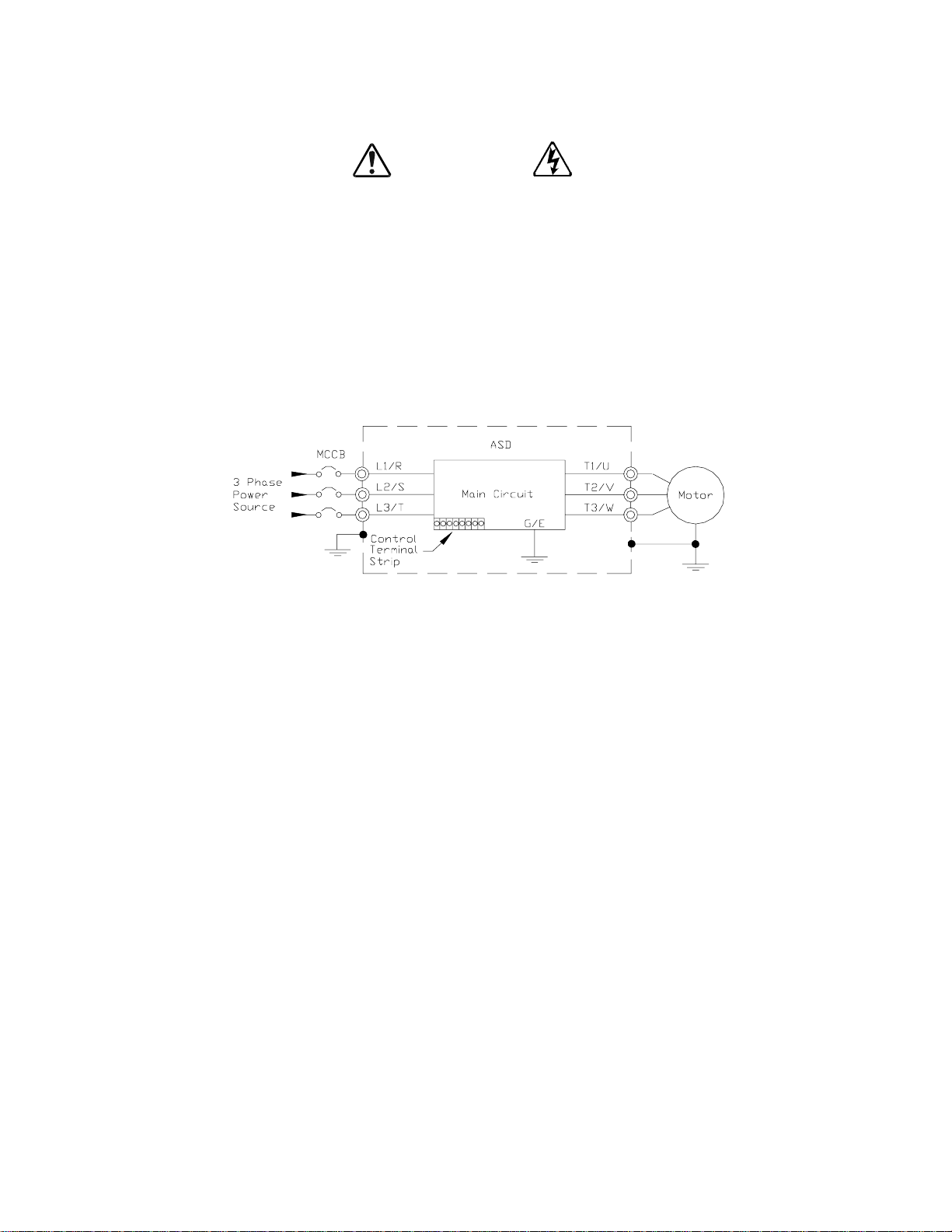
Connect the inpu t and output power lines of the ASD as shown in Figure 4.
Note: In the event that the motor rotates in the wrong direction when pow ered up, reverse
any two of the three A SD output power leads connected to the motor.
Figure 4. ASD/Motor connection diagram.
Figure 18 on pg. 26).
Connect the 3-phase input power to the input terminals of the ASD at L1/R, L2/S, and L3/T. Conne ct
the output of the ASD to the motor from terminals T1/U, T2/V, and T3/W. The input and output
conductors and terminal lugs used shal l be in accordance with the specifications lis ted in the section
titled
Cable/Terminal Specifications on pg. 159.
Install a molded c ase ci rcuit bre aker (MCC B) or fuse bet ween the 3-ph ase power sourc e and th e ASD in
accordance with the fault current setting of the ASD and 2005 NEC Article 430.
CAUTION
For 600 volt ASDs, t he 15 HP or less ASDs (P/N VT1 30Q7U6015 – 616 0) re quire a class -J fuse ra ted a t
600 Volts/30 A.
On some Q7 devices 12-Pulse ope ration is available. A phase-shifting transformer must be suppli ed by
the user when configure d for 12-pulse operation.
External fuses may required on the ASDs that are configured for 12-pulse operation.
Use either the Ferra z Shawmut S em iconductor fuse (P/N A70QS200) an d fuse block P234C, or the
Toshiba ASD-FUSEKIT-12P. The Toshiba kit includes the required fuses and the mounting hardware
for the fuses.
Q7 ASD Installation and Operation Manual 17
Page 24

Lead Length Specifications
Adhere to the NEC and any local co des during the installation of ASD/Motor systems. Exces sive lead
lengths may adversel y ef fec t the p erforma nce of the m otor. Special cables are not r equi red. Lea d leng ths
from the ASD to the motor in excess of those listed in
output of the ASD. Table 2 lists the suggested maximum lead lengths for the listed motor voltages.
Table 2. Suggested max im um le ad lengths.
Table 2 may require filters to be added to the
Model
230 Volt All 1000 feet
460 Volt
600 Volt
Note: Contact Toshiba for application assistance when using lead lengths in excess of those
listed.
PWM Carrier
Frequency
< 5 kHz 600 feet
≥ 5 kHz 300 feet
< 5 kHz 200 feet
≥ 5 kHz 100 feet
NEMA MG-1-1998 Section IV Part 31
Compliant Motors
2
Exceeding the peak voltage rating or the allowable thermal rise time of the motor
insulation will reduce the life expectancy of the motor.
For proper operation, the carrier freq uenc y mus t be 2.2 kHz or above except when
operating in the Constant Torque or Variabl e Torque modes.
Startup and Test
Perform the following checks before turning on the unit:
• L1/R, L2/S, and L3/T are connected to the 3-phase input power.
• T1/U, T2/V, and T3/W are connected to the motor.
• The 3-phase input voltage is within the specified tole rance.
• There are no shorts and all grounds are secured.
18 Q7 ASD Installation and Operation Manual
Page 25

I/O and Control
The Q7 ASD can be controlled by several input types and combinations thereof, as well as operate
within a wide range of output frequency and voltage levels. This section describes the ASD control
methods and supported I/O functions.
Control Terminal Strip
The Control Terminal Strip PCB (P/N 48570) supports discrete and analog I/O functions.
The Control Terminal Strip is shown in Figure 6 on pg. 22. Table 3 and lists the names, the default
settings, and the descriptions of the input and output terminals.
Figure 18 on pg. 26 shows the basi c connection diagram for the Q7 syste m.
Table 3. Control Terminal Strip default assignment terminal names and functions.
Terminal
Name
ST Discret e Input
RES Discr ete Input Reset — Multifunct ional programmable discrete input.
F Discrete Input Forward — Multifunctional programmable discrete input .
R Discret e Input Reverse — Multifunctional programmable discrete input.
S1 Discrete Input
S2 Discrete Input Preset Speed 2 — Mul tifunctional programmable discre te input.
S3 Discrete Input
S4 Discrete Input Emergency Off — Multi functional programmabl e discrete input.
RR Analog Input
RX Analog Input
II Analog Input
VI Analog Input
P24 DC Output 24 VDC @ 50 mA output. Figure 12 on pg. 25.
PP DC Output PP — 10.0 VDC voltage source for the ext ernal potent iometer. Figure 13 on pg. 25.
OUT1 Discrete Output
OUT2 Discrete Output Reach Frequency — Multifunctional programmable discrete output.
FP Output
AM Output
FM Output
FLC Output F a ul t re la y (co m m o n) .
FLA Output F a ul t re la y (N. O .) .
CC — Control common (Do Not connect to Earth Gnd).
Discrete Input Terminals
Analog Input terminals reference CC.
Input/Output
Standby (jumper to CC to operate the unit) — Multifunctional
programmable discre te input (see
inform ation on this termin al).
Fire Speed — Multifunctional programmable discrete input.
Damper Fdbk — Mult ifunction al programmable discrete input (connect
to CC to operate the unit).
RR — Multifunction programmable analog input
(0.0 to 10 volt input — 0 to 80 Hz output). Reference CC.
RX — Multifunctional programmable analog input
(-10 to +10 VDC input — -80 to +80 Hz output). Refere n c e C C .
II — Multifuncti onal programmable analog input (4 [0] to 20 mADC
input — 0 to 80 Hz output) (see
the II terminal). Reference CC.
VI — Multifunctional programmable analog input
(0 to 10 VDC input — 0 to 80 Hz output). Reference CC.
Damper Command — Damper Command — Mu ltifunc tional
programmable output that is used to open/close the 120 VAC damper
motor power circuit when the motor is ASD-driven.
Frequency Pulse — an output pulse train that has a freq uency which is
based on the output frequen cy of the ASD.
Produces an output current that is proportional to the magnitude of the
function assigned to this terminal (see
⇒
On = connected to CC.
Terminal Function
(default setting if pr ogrammable)
Installation Notes on pg. 14 for further
Figure 6 on pg. 22 for the location of
Table 6 on page 48).
Circuit Config.
Figure 8 on pg. 25.
Figure 9 on pg. 25.
Figure 10 on pg. 25.
Figure 11 on pg. 25.
Figure 14 on pg. 25.
Figure 15 on pg. 25.
Figure 16 on pg. 25
Figure 17 on pg. 25.FLB Output Fault re la y (N. C .) .
Q7 ASD Installation and Operation Manual 19
Page 26

I/O Terminal Descriptions
Note: The programmable term inal assignments may be acc es sed and changed from their
default settings as mapped on
ST — The default setting for this terminal is ST. The function of this input as ST is a Sta ndby mode
controller (system is in Standby when on). As the default setting, this terminal must be connected to
CC for normal operation. If not connected to CC, Off is displayed on the LCD screen. This input
terminal may be programm ed to any 1 of the 68 functions that are listed in
RES — The default setting for this terminal is Reset. A momentary connection to CC resets the ASD
and any fault indications from the display. Reset is effect iv e when fau lt ed on l y.
F — The default setting for this terminal is Forward Run. Forward Run runs the motor in the
Forward direction when it is on. This input terminal may be programmed to any 1 of the 68 function s
that are li s t ed in
R — The default setting for th is terminal is Revers e Run. Rever s e Run runs the motor in the Reverse
direction when it is on. This input terminal may be programmed to any 1 of the 68 functions that are
listed in
S1 — The default setting for this terminal is Fire Spee d . The function of this input as Fire Speed is to
run the motor at the Preset Speed #1 setting when it is on (se e
may be activated by a fire alarm signal or fire sensing device. This discrete input terminal may be
programmed to any 1 of the 68 functions that are liste d in
Table 7 on page 130.
Table 7 on page 130.
pg. 36.
Table 7 on page 130.
Preset Speed #1 on pg. 90 ). This t erminal
Table 7 on page 130.
S2 — The default setting for this terminal is S2. The function of this input as S2 is to run the motor at
Preset Speed #2 (see
to any 1 of the 68 functions that are listed in Table 7 on page 130.
S3 — The default setting for this terminal is Damper Feedba ck. The function of this input as Damper
Feedback is to provide an indication that the damper is open. Connecting Damper Feedback to CC is
required for normal sy st em operation. This discre te input terminal may be programmed to any 1 of the
68 functions tha t are listed in
S4 — The default setting for this terminal is Emergency Off (normally closed). The function of this
input as Emergency O ff is to remove power from the output of the AS D and may apply a supplemental
braking system usi ng the method selected at the Emg Off Mode selection paramet er. This input
terminal may be programm ed to any 1 of the 68 functions that are listed in
RR — The default function assigned to this terminal is to carry out the Frequency Mode #1 setting.
The RR terminal accepts a 0 – 10 VDC input s ignal and controls the function assigned to this terminal.
This inpu t terminal may be programmed t o control the speed or torque of the motor. It may also be used
to regulate (li mi t) the speed or torque of the motor. The gain and bias of this t erm inal may be adjusted
for application-specific suitability.
RX — The RX termina l accepts a ±10 VDC input signal and c ontrols the function ass igned to this
terminal. This inp ut term inal m ay b e progr ammed t o con trol the sp ee d, tor que, or dire ct ion of the mo tor.
It may also be used to regulat e (limit) the speed or torque of the moto r. The gain and bias of this
terminal m ay be adjusted for application- specific suitability.
Preset Spee d #2 on pg. 90) when it is on. This input termina l may be programmed
Table 7 on page 130.
Table 7 on page 130.
II — The func tion of the II input is to receive a 4 – 20 mA input signal that controls a 0 – 80 Hz output.
This input te rminal may be progr ammed to cont rol the spee d or torque of the m otor an d may not be used
when using the VI in put. Also, the gain and bias of this terminal may be adjuste d.
20 Q7 ASD Installation and Operation Manual
Page 27

VI — The function of the VI input terminal is to rec eive a 0 – 10 VDC input signal that controls a
0 – 80 Hz output. This input te rm inal may be programmed to control the speed or torque of the motor
and may not be used when using the II input. Also, the gain and bias of this te rminal may be adjusted.
P24 — +24 VDC @ 50 mA power supply for customer use.
PP — The function of output PP is to provide a 10 VDC output that may be divided using a
potentiome ter. The tapped voltage is applied to the RR input to provide manual cont r ol of the RR
programmed functi on.
OUT1 — The default sett ing fo r thi s output te rmina l is Damper Command. This te rmina l may be used
to switch the externally-supplied On/Off power to the damper motor. The OUT1 contacts may be
programmed to provide an indication th at 1 of 60 possib le events has t aken place. This function may be
used to signal ext ernal equipment or to activate the brake. The OUT1 contact is rated at 2A/250 VAC.
OUT2 — The default setting f or this output terminal is ACC/DEC Complete. This output ter minal
may be program me d to provide an indication that 1 of 60 possi ble events ha s taken place. This function
may be u sed to signal ex ternal equipment or to activate the brake. The OUT2 contact is rated at 2A/25 0
VAC.
FP — The default function of this output terminal is to output a series of pulses at a rat e that is a
function of the output frequency of the ASD. As the output frequency of the ASD goes up so does the
FP output pulse rate. This term inal may be programmed to provide output pulses at a rate that is a
function of the output frequency or the magnit ude of any 1 of the 31 the functions listed in
Table 6 on
page 48.
AM — This output te rm inal produces an output curre nt that is proportional to the output frequency of
the ASD or of the magni tu d e of the fun ction assigned to this terminal. The available ass ignment s fo r
this outpu t terminal are listed in
Table 6 on page 48.
FM — This output terminal produces an output current that is proportional to the output frequency of
the ASD or of the magni tu d e of the fun ction assigned to this terminal. The available ass ignment s fo r
this outpu t terminal are listed in
Table 6 on page 48.
FLC — FLC is the middle leg of a single-pole double-throw (rel ay) switch. This FLC contact of the
relay is sw itche d be tween FLB and FLA. This contac t may b e programm ed to sw itch be tween FLB and
FLA as a function of any 1 of the 60 condition s li sted in
Table 8 on page 133.
FLB — One of two contacts that, under user-defined conditions, connect to FLC (see Figure 5).
FLA — One of two contacts that, under user -defined conditions , connect to FLC (see Figure 5).
Note: The FLA and FLC contacts are rated at 2A/250 VAC. The FLB contact is rated at
1A/250 VAC.
CC — Control common (Do Not connect to Earth Gnd).
Figure 5. FLA, FLB, and FLC switching contacts shown in the de-energized state.
Note: T h e rel ay is sho wn in th e Faulted or
de-energized condition. During
normal system oper ation the relay
connection is FLC-to-FLA.
Q7 ASD Installation and Operation Manual 21
Page 28

Figure 6. Control Terminal Strip PCB.
1
SW1 and SW2 may be switched to
change the full-scale reading of the
AM and FM output terminals. See
the AM Terminal Assignment and
the FM Terminal Assignment
descriptions for further information
on SW1 and SW2.
CN7A
{
0–1 mA 4–20 mA
SW1
{
0–1 mA 4–20 mA
SW2
TB
II Terminals
Shown below are the TB1 input and output te rmina ls of the Control Terminal Strip PCB.
For further information on these terminals see pg. 19.
RES
22 Q7 ASD Installation and Operation Manual
RRP24
F
ARS1S2S3S4C CA
OUT1 OUT2
Page 29

Q7 ASD Control
r.
l
The Control PCB (P/N 56000) serves as the primary control source for the Q7 ASD and receives input
from the
Keypad.
The Control PCB has been enhanced to support two new functions: Multiple Protocol Commun ications
and the ability to communicate in either half- or f u ll-duplex mode s.
Using the optional multiple-protocol communications interface: the ASD-NANOCOM, the Control
PCB may be configured for the type of co mmunications protocol being received and respond
appropriate ly to the sending device. The ASD-NANOCOM connect s to the J4 and J5 connectors
(see Figure 7). A jumper PCB (P/N 55365) is required at the J4 connector if not using the ASDNANOCOM.
Control Terminal Strip PCB, an Option Card, RS232/485 Communic ations, or the Q7 ASD
The ASD-NANOCOM must be setup to support the des ired communications protocol via Program
Com m Settings . Consult the ASD-NANOCOM User’s Manual (P/N 10572-1.000-000) for a complete
listing of the setup requirements.
Half or Full duplex communica tions is available when using RS232/485 communications. The jum pers
at the JP1 and the JP2 connectors may be moved from one position to the other to facilitate either halfor full-duplex operation. If no jumpers are used the system will operate in the full duplex mode.
For more information on the Q7 ASD communication requirement s , please visit
WWW.TIC.TOSHIBA.COM to acquire a copy of the 7-Series Communications User Manual and
WWW.ICCDESIGNS.COM to acquire a copy of the ASD-NANOCOM User Manual.
Contact your Toshiba representative if more informat ion is required on the ASD-NANOCOM.
Figure 7. Control Board of the Q7 ASD (P/N 56000).
Keypad
connection (CN8).
Common Serial
(TTL) I/O (CNU2).
RS232/RS485
signal I/O (CN3).
CNU3
CN2
⇒
RS232/RS485
signal I/O (CNU1).
CNU4
JP1 jumpers - Half-/Full-Duplex selection.
Q7 ASD Installation and Operation Manual 23
ASD-NANOCOM.
25-pin D-type connecto
Connects to the Control Termina
Strip PCB (CN7).
Page 30
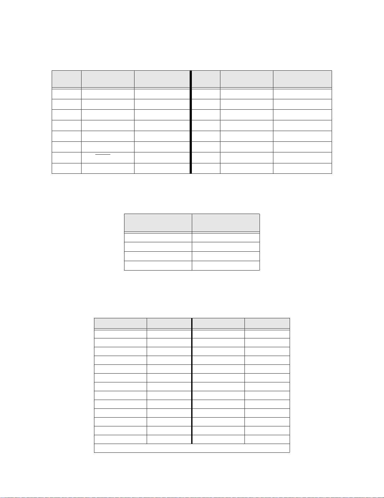
CNU1 and CNU2 Pinout
CNU1 and CNU2 pinout (RJ-45 con nec tors).
Pin #
1 P24 P24 1 P24 P24
2 Gnd Gnd 2 Gnd Gnd
3 Tx (-) RXA 3 Rx Tx
4 Rx (+) TXA 4 Gnd Gnd
5 Rx (-) TXB 5 Tx Rx
6 Tx (+) RXB 6 Gnd Gnd
7 RS232/485 CNU3 Pin-7 7 Open Open
8 Gnd Gnd 8 Gnd Gnd
CNU1 Pinout
(Controller PCB)
TTL/RS232/RS485
Interface
Pin #
CNU2 Pinout
(Controller PCB)
TTL/RS232/RS485
Interface
CNU3 Pinout
CNU3 is used for RS232/485 seri al communications.
Pin Number
1 RS232/485 Signal +
2 RS232/485 Signal 3 RS232/485 Signal Gnd
4 Shield
CNU3 Pinout
(Controller PCB)
CN7 Pinout
CN7 connects to CN7A of the Co nt r o l T e rmina l S tr ip PCBA.
Table 4. CN7 pin out as signments. Programm able terminals are lis ted as their default settings.
Pin Number Function Pin Number Function
1 PP 14 II
2 FL 15 S1
3 VI 16 R
4 RR 17 S3
5 FM 18 S2
6 RX 19 N15
7 FP 20 S4
8 AM 21 P15
9 *OUT1 22 P24
10 *OUT2 23 CC
11 ST 24 CC
12 RES 25 CC
13 F — —
Note: * Open collector output s.
24 Q7 ASD Installation and Operation Manual
Page 31

I/O Circuit Configurations
Figure 8. Discrete Input. Figure 9. RR Input.
Figure 10. RX Input. Figure 11. VI/II Input.
Figure 12. P24 Output. Figure 13. PP Output.
Figure 14. OUT1 /OUT2 Outp ut. Figure 15. FP Output.
Figure 16. AM/FM Output. Figure 17. Fault Relay (active fault).
Q7 ASD Installation and Operation Manual 25
Page 32

Typical Connection Diagram
Figure 18. Q7 ASD typical connection diagram.
Note: When connecting multi ple wire s to th e PA, PB, P C, or PO termi nals, do not con nect a
solid wire and a stranded wire to the same terminal.
26 Q7 ASD Installation and Operation Manual
Page 33

Q7 ASD Keypad
Q7 Keypad Feat ures
The Q7 Keypad is compris ed of an LCD dis play, three system status L EDs, and eight k eys. These i tems
are described below and their locations are provided in
The keypad may be mounted remotely. See pg. 29 for information on re mot e mounting.
Speed Ct rl |L oc a l/R emote Key — Toggles the system to and from the Local and Remote mo des. The
LED is on when the system is in the Local mode. The Local mode allows the Frequency control
functions to be carried out via the Q7 Keypad.
The Remote mode enables the Frequency control functions to be carried out via any one of the
following methods:
• Pulse Input ,
• Motorized Pot,
• Communication Card,
• RS232/485,
• Common TTL,
•Binary/BCD,
•LED Keypad,
• Option Card RX2,
•RX,
•RR, or
• VI/II.
Figure 19 on pg. 28.
The Remote Frequency control mode selection m ay be made via Program ⇒ Utility Group ⇒
Frequency Mode.
Up/Down Arrow Key — Increases /de creas es the value of t he sele cted par am eter o r scro lls u p/do wn the
menu listing (continues during press and hold).
Run Mode|Manual/Auto Key — Allows the Q7 ASD to receive Run commands (i.e. , Stop, Run,
Forward, etc.) from either the Q7 keypad (Manual) or remotely (Auto) (e. g., RS232/485, Option Card
RX2, etc.).
Read/Write Key (R/W) — Selects a menu item to be changed or ac cepts and records the changed data
of the se le ct ed f ie ld .
LCD Display — Displays configuration information, performance data (e.g., motor frequency, bus
voltage, torque, etc.), and diagnos tic information.
Stop|Reset Key — Issu es the Off command (decelerates to Stop at the programmed rate) if pressed
once while in the Manual mode , or i nit iate s an Emergency Off (terminates the ASD output and appl ies
the brake if so configured) if pressed twice quickly from the Manual or Auto mode.
Run Key — Issues the Run command while in the Manual mode.
Local/Run/Manual System Status LEDs — O n w h il e active.
Setup/Progr am/Monitor Key (SP M) — Pro vid es a mea ns to ac ce ss t he r o ot m enus . Pres s ing th e SPM
key repeatedly loops the system through the ac tive root menus (see
Figure 24 on pg. 34).
Q7 ASD Installation and Operation Manual 27
Page 34

Figure 19. The Q7 Keyp ad.
LCD Display
RUN Mode
Manual/Auto key
Speed Ctrl
Local/Remote
Key
Up/Down
Arrow Ke y s
Setup/Pr o gra m/
Monitor (SPM) Key
Keypad Operation
The Q7 Keypad is the primary input/output device for the user. The Q7 Keypad may be used to
monitor syste m functions, input data into the system, or perform diagnos tics.
Press the SPM key to loop through the root menu selections. Use the R/W key and the Up and Down
arrow keys to access and change th e system para meters as descri bed in the sectio n titl ed
Changes on pg. 32.
From any menu, press the SPM key to return to th e root menu.
LOCAL, RUN,
and MANUAL
Status LEDs
Run Key
|
Reset Key
Stop
Read|Write Key
Default Setting
Panel Control Menu
The (Program ⇒) Panel Control menu allows for qu ick access the ASD param eters listed below.
Changes to the listed parameters are effective for commands received via the Q7 Ke ypad only.
Direction — Forward or Reverse.
Ramped PWM — The PWM frequency ramps from 9.99 kHz to 5 kHz as the ASD output frequency
increases.
PID Control — This feature enables/disables the PID feedback function.
Reset Selection — Enables/Disables the a bility to reset the system from the panel.
Accel/Decel Selection — 1 of 4 Accel/Decel profiles may be selected and run.
V/f Group — 1 of 4 V/f profiles may be selected and run.
Stop Pattern — The Decel Stop or Coast Stop settings determines the method used to stop the motor
when using the Stop|Reset key of the keypad.
Note: The Stop Pattern setting has no effect on the Emergency Off settings .
28 Q7 ASD Installation and Operation Manual
Page 35

Keypad Remote Mounting
The Q7 ASD may be controlled from a remotely-mounted keypad. For safety and application-specific
reasons, some ASD instal lations will warrant that the operator not be in the vicinity during operat ion or
that the keypad not be att ached to the ASD housing. The keypad may be mounted either with or without
the optional Remote Mounting Kit (P/N ASD-MTG-KIT). The ease of installation is enhanced by the
Remote Mounting Kit which allows for easier cable routing and keypad placement.
Remote mounting will also allow for multipl e keypad mountings at one location if controlling and
monitoring several AS Ds from a central location is required.
The keypad can operate up to 9 feet away from the ASD. A keypad extender cable is required for remote
mounting. The keypad extender cable is available in a 9-ft. length and may be ordered through your sales
representative.
The optional dust cov er (P/N AS D-BP C) may be us ed to cover the front panel opening of the ASD
housing after removi ng the keypad.
Remote Keypad Required Hardware
Keypad Mounting Hardware
• 6-32 x 5/16” Pan Head Screw — P/N 50595 (4 ea.)
• #6 Split-Lock Wa sher — P/N 01884 (4 ea.)
• #6 Flat Washer — P/N 01885 (4 ea.)
Bezel Plate Mounting Hardware
• Bezel Plate — P/N 52291
• 10-32 Hex Nut — P/N 01922 (4 ea.)
• #10 Split-Lock Wa s her — P/N 01923 (4 ea.)
• #10 Flat Washer — P/N 01924 (4 ea.)
• Dust Cover — P/N ASD-BPC (Optional)
Extender Cable
• ASD-CAB9F-Q7: Cable, 9 ft.
Keypad Installation Precautions
Install the unit secu rely in a well ven til ated a rea tha t is o ut of direc t sunl igh t using the four m ount ing holes
of the keypad. The ambient temperature rating for the keypad is 14 to 104° F (-10 to 40° C).
• Select a mountin g lo cation that is easily accessible by the user.
• Avoid insta llation in areas wher e vibration, heat, humidity, dust, meta l particles, or high levels of
electrical noise (EMI) ar e p resent.
• Do not instal l the keypad where it may be exposed to flamm able chemicals or gases, water, solv ents,
or other fluids.
• Turn the power on only after securing the fron t cove r to the ASD.
Q7 ASD Installation and Operation Manual 29
Page 36

Keypad Remote Mounting w/o the ASD-MTG-KIT
Note: See Figure 20 for the dimensions and the item locations re ferenced in steps 1 through 5.
1. At the keypad mounting location, identify and mark the location of the 3.80” by 3. 29” hole and the
7/32” screw holes.
2. Cut the 3.80” by 3.29 ” rec tangular hole.
3. Drill the four 7/32” screw holes.
4. Attach and secure the keypad to the front side of the mounting location using the four 6-32 x 5/16”
pan head screws, the #6 spl it lock washers, and the #6 flat washers.
5. Connect the extension cable.
Keypa d Dim e ns ions (mountin g)
Figure 20. Keypad Mounting Dimensions.
Keypad Remote Mounting using the ASD-MTG-KIT
Note: See Figures 21 and 22 for the dimensions and the item locations referenced in steps 1
through 6.
1. At the keypad mount ing l ocati on, ide nti fy and mark t he l ocati ons of the 5.00” b y 4.60” ho le and t he
four 11/32” screw holes.
2. Cut the 5.00” by 4.60 ” rec tangular hole.
3. Drill the four 11/32” holes.
4. Attach and secure the Bezel plate to the front s ide of the mounting location using the four 10-32
hex nuts, #10 split lock washers, and the #10 flat washers.
5. Attach and secure the keypad to the front side of the Bezel plate using the four 6-32 x 5/1 6” pan
head screws, #6 split lock washers, and the #6 flat washers.
6. Connect the extension cable.
30 Q7 ASD Installation and Operation Manual
Page 37

Keypa d ASD- MTG-KIT Dimensions ( mo unting)
C
l
a
e
Figure 21. Keypad Bezel Plate Mounting Dimensions.
Mounting Hole
5.00
4.25
11/3 2" Scre w Hole ( 4)
38
SPEED CTRL
LOCAL/REMOTE
RUN MODE
MANUAL /AUTO
SETUP
PROGRAM
MONITOR
READ
WRITE
LOCAL
STOP
RESET
MANUAL
RUN
RUN
4.60
Bezel Plate Bezel Plate
Front View Side View Back View
Figure 22. Screw Length Precaution.
AUTION: Failure to use the correct hardware may result in damage to the outer surface of the keypad pane
nd/or improper s eating of the panel to the bezel plate. Use ca ut ion when mounting the keypad assem bl y t o
nsure that the internal thr ead cl ear ance is maintained.
Correct Incorrect
Q7 ASD Installation and Operation Manual 31
Page 38

System Operation
Operation (Local)
Read and understand all safet y warnings be fore operating this equipmen t!
To run the motor perform the following steps:
1. Press the SPM key until the Output Frequency screen is displayed (see Figure 23).
2. Press the Speed Ctrl|Local/Remote key to enter the Local mode (green Local LED illuminates).
3. Press the Run Mode|Manual/Auto key (green Manual LED illuminates).
4. Press (and hold) the Up/Down arrow key until the displayed Frequency Command value is at the
desired sett ing.
5. Ensure that there are no personnel around or near the motor or the motor-driven equipment.
6. Press the Run key and the motor runs at the Frequency Command value.
Note: The speed of the motor may be changed while the motor is running by using the Up/
Down arrow ke ys to change the Frequency Command value. To chang e th e dire ct ion
press and hold the R/W key and momentarily press the Up or Down arrow key
(Up=Forward/Down=Reverse).
7. Press the Stop|Reset key to stop the motor.
Figure 23. Frequency Command screen.
Default Settin g Chang es
To change a parameter setting from the keypad, go to the Program menu or the Setup menu by
pressing th e SPM key unt il the desired menu is disp layed.
From the Program menu press the Up/Down arrow key until t he desired parameter group is
displayed. Press the R/W key to access the sub- me nu listing. Press the Up/Down arrow keys to
access the parameter to be changed.
From the Setup menu press the R/W key to access the sub-menu items and then use the Up/Down
arrow key to access the par am eter to be changed.
Once a parameter setti ng has bee n accessed, press the R/W key to enter the Edit mode (screen title
flashes). Use the Up or Down arrow keys to change the parame ter setting.
Press the R/W key when done to accept and save the c hanged setting and remain in the active menu, or
press the SPM key to retain the changed sett ing in volatile memory (los t when powered down or reset)
and return to the root menu.
Note: Some parameters use the unsaved changed value until the ASD is Reset or powered
off (e.g., Frequency Command, Accel/Decel, etc.).
Repeated R/W key entrie s loop the men u through its full list of items of the active sub-menu. From any
menu, press the SPM key to return to the root menu. Re peated SPM entries loop the system through the
root menus as shown in
For a complete listing of the Program menu and Setup menu items, see the section titled Menu
Navigation on pg. 36. The menu items are mapped for convenience.
Figure 24 on pg. 34.
32 Q7 ASD Installation and Operation Manual
Page 39

Search (for default setting changes)
A listing of all paramete rs that have bee n changed from the default set tings may be viewed sequentially
by acces si n g th e Search screen (Program
The Search feature allo ws th e u ser t o v i ew (or ch an ge ) th e pa ram eter s t ha t a re di fferen t f rom the fa ct ory
default settings. From the Search screen, press the R/W key to start the Search function. Once started,
the system automat ical ly scrolls through al l of the system para meters and ha lts onc e reaching a changed
parameter.
After stopping at a changed parameter, the Up or Down arrow keys may be pressed once to c ontinue
scrolling forward. Wi th eac h Up or Down arrow key pressed from a stop, the system scrolls and stops at
the next paramet er tha t has been changed.
Press the R/W key while a changed parameter is displayed to access the settings of the changed
parameter. Use the Up or Down arrow keys to change the setting.
Press the R/W key when done to accept and save the c hanged setting and remain in the active menu, or
press the SPM key to retain the changed sett ing in volatile memory (los t when powered down or reset)
and return to the root menu.
Note: Some parameters use the unsaved changed value until the ASD is Reset or powered
off (e.g., Frequency Command, Accel/Decel, etc.).
Pressing the SPM key when done searching or when halted at a changed param eter returns the system
to the primary menu loop.
⇒
Search).
Q7 ASD Installation and Operation Manual 33
Page 40

System Configuration and Menu Options
Root Menus
The SPM ke y ac ce s se s the (a ct i ve ) roo t menus of the Q7: the Output Frequency, Setup, Program,
Monitor, and the Alarm and Fault screens (if active). From either mode, press the SPM key to loop
through to the other modes (see
Figure 24. Root menu mapping.
Output Frequency Screen
Frequency Setting
While operatin g in the Local mode (Local LED is illuminated on the LCD keypad), the running
frequency of the motor may be set from the Output Frequency screen. Using the Up/Down arrow
keys, enter the desired Frequency Command value and then press the Run key. The motor will run at
the Frequency Command speed and, by using the Up/Down arrow keys, may be changed while
running.
Figure 24).
Setup Screen
The Setup screen allows quick-access to th e following commonly used parameters:
• Accel Time #1 (pg. 44),
• Switch-on-the-Fly (pg. 121),
• V/f Pattern (pg. 126),
• Type Reset (pg. 124),
• VI/II Speed Frequency #2 (pg. 126),
• VI/II Speed Reference #2 (pg. 127),
• VI/II Speed Frequency #1 (pg. 126),
• VI/II Speed Reference #1 (pg. 127),
• Lower Limit Freq ue nc y (pg. 72),
• Upper Limit Frequency (pg. 125), and
• Decel Time #1 (pg. 58).
Program Menu
The Program Menu allows the user ac ce ss to parameters that setup the input and output specifications
of the Q7 A S D. Thes e settin gs are usual ly appli catio n-s pecifi c and will re quire setup . The Setup screen
provides easy-access to the most com mon setup parameters. See the section titled
pg. 36 for a complete list ing of the Q7 parameters and menu navigation assistance.
Menu Navigation on
34 Q7 ASD Installation and Operation Manual
Page 41

Monitor Mode
The Monitor mode allows for the monitoring of motor per formance variables, control settings, and
configuration data during motor operat ion. There are 30 items that may be moni tored from this mode.
The items are listed and described below.
Note: The Monitor parameters are read-only.
Trip Hold Frequency — If tripped, this fiel d reco rds the at-trip frequency. Otherwise, the current
output frequency is dis played.
Past Trip #4 — This f eature reads and stores trip records and is the first o f f o u r record ed tr ips.
Past Trip #3 — This f eature reads and stores trip records.
Past Trip #2 — This f eature reads and stores trip records.
Past Trip #1 — This feature reads and stores trip records and is the last of four recorded trips.
Trip Co de— If tripped, this field displays the trip code (e.g., E-Stop). If not tripped No Error is
displayed.
AM Output— Displays the AM output as a percentage of its full range.
FM Output — Displays the FM output as a percen tage of its full range.
RX2 Input — Displays the RX2 input as a percentage of its full range.
RX Input — Displays the RX input as a perc entage of its full range.
*VI/II Input — Displays the VI/II input as a percentage of the full range of the VI/II value.
Note: The VI/II input r epres ents two analog i nput s (and termi nal s). The VI input terminal is
used for a 0 – 10 VDC ana log sig nal an d the II input terminal is used for cur rent l oop
applications, such as with a 4-20 mA signal. Either may be used as a frequency or
torque command source; however, the two cannot function simultaneous ly.
Throughout this manual they will be listed as VI/II.
RR Input — Displays the RR input as a percentage of its full range.
Direction — Displays the Forward/Reverse status .
Peak Current — Shows the high est c urre nt le vel ac hieve d sinc e the last star tup o r re set. Th is va lue is
displayed as a percentage of the full rating of the ASD or as an amperage (se e
Current on pg. 125).
Kilowatt Hours — Displays accumul ated Kilowatt hours. Saved a t 2-hour intervals.
Output Power — Shows the instantaneous output power level of the ASD.
Input Power — Shows the instantaneous input power level to the ASD.
ASD Load — Shows the instantaneous load placed on the ASD.
Motor Load — Shows the instantaneous motor load requirements.
ASD Overload Ratio — Displays the relationship of time to the magnitude of the ASD overload as a
ratio. A higher overload means a shorter run-time in this condition.
Motor Overload Rati o — Displa ys the relationship of time to the magnitude of the motor overload
as a ratio. A higher overload means a shorter run-time in thi s condition.
PID Feedback — Displays the instantaneous PID feedback value.
Post Compensation Frequency — Displays the output frequenc y of the ASD afte r the appl icat ion of
the waveform adjustment compensation for changes in the input voltage.
Run Time — Displays the accumulated run-time since the last reset or power up of the ASD.
Output Terminals — Shows the activ e dis crete output terminals.
Input Terminals — Shows the active discret e input terminals.
Output Vo ltag e — Shows the instant ane ous output voltage as a percentage of the rating of the ASD
or as a voltage (see
DC Voltage — Shows the instantaneous DC bus volt age as a percentage of the rating of the ASD or
as a voltage (see
Output Current — Shows the instantaneous output current as a percentage of the rating of the ASD
or as a current (see
Frequency Command — Displays the current frequency command.
Units f o r Voltage and Cur r en t on pg. 125).
Units for Voltage and Current on pg. 125).
Units for Voltage and Current on pg. 125).
Units for Voltage and
Q7 ASD Installation and Operation Manual 35
Page 42

Menu Navigation
Listed below are the mapped menu items of the Q7 ASD.
Q7 ASD Menu Items
Primary Menu Menu Item Sub-menu Item s Primary Menu Menu Item Sub-menu Items
Output
Frequency
Displays output frequency.
Press Up/Down Arrow key to change setting. Maximum Voltage #2
Display
Setup
Press Up Arrow key to scroll menu
items.
Press R/W key t o acc ess m enu ite ms and
the Up/Down Arrow keys to change
value.
Press SPM key to return to Primary
Menu.
Program
Press Up Arrow
key to scroll
menu items.
Press R/W key to
access menu
items and the Up/
Down Arrow
keys to chan ge
value.
Press SPM key
to return to
Primary Menu.
Search
Press R/W key to
search.
Press Up Arrow
key to go to next.
Press SPM key to
return to Primary
Menu.
Fundamental
#1
Press R/W key to
access displayed
menu item or press
Up Arrow key to
view subsequent
menu items.
Press the Up/Down
Arrow key to
change acce ssed
menu item.
Press SPM key to
exit.
Program
Press Up Arrow
Accel Time #1 Torque Boost #2
Decel Time #1
Upper Limit Frequency Accel #2 Time
Lower Limit Frequency Decel Time #2
VI/II Speed Reference #1 Accel/Decel #2 Pattern
VI/II Speed Frequency #1
VI/II Speed Reference #2
VI/II Speed Frequency #2 Panel Stop Pattern
Type Reset Panel V/f Group
V/f Pattern Panel Acc/Dec Select
Switch-on-the-Fly Panel Reset Select
(Electronic) Thermal
Protection #1
Changed fr om De fault
Parameters
Maximum Output
Frequency
Base Frequency 1 R T ermi nal
Voltage Compensati on for
Dead Time
Maximum Voltage #1 RES Terminal
Disa bl e Forward Run/
Disa bl e R ev erse Run
Upper Limit Frequency S2 Terminal
Lower Limit Frequency S3 Terminal
V/f Pattern S4 Terminal
Torque Boost #1 S5 Terminal
Accel Time #1 S6 Terminal
Decel Time #1 S7 Terminal
Accel/Decel #1 Pattern S8 Terminal
S-Pattern Lower Limit
Adjustment
S-Pattern Upper Limit
Adjustment
key to scroll
menu items.
Press R/W key
to acces s m enu
items and the
Up/Down
Arrow keys to
change val ue.
Press SPM key
to return to
Prim ar y M e nu.
Fundamental
#2
Press R/W key to
acces s displ ay e d
menu item or press
Up Arrow key to
view subsequent
menu items.
Press th e Up/Down
Arrow key to
change accessed
menu item.
Press SPM key to
exit.
Panel
Control
(access method
same as
Fundamental #2)
Input
Terminals
Press R/W key to
acces s displ ay e d
menu item or press
Up Arrow key to
view subsequent
menu items.
Press th e Up/Down
Arrow key to
change accessed
menu item.
Press SPM key to
exit.
Base Frequency 2
(Electronic) Thermal
Protection #2
Accel/Decel #1 Switchin g
Frequency
Panel Direction
Panel PID Control
Ramped PWM
F Terminal
ST T erminal
S1 Terminal
S9 Terminal
S10 Terminal
36 Q7 ASD Installation and Operation Manual
Page 43

Q7 ASD Menu Items
Primary Menu Menu Item Sub-menu Items Primary Menu Menu Item Sub-menu Items
Program
Press Up Arrow
key to scroll
menu items.
Press R/W key
to access menu
items and the
Up/Down
Arrow keys to
change value.
Press SPM key
to return to
Primary Menu.
Input
Terminals
Output
Terminals
Press R/W key to
access displayed
menu item or press
Up Arrow key to
view subsequent
menu items.
Press th e Up/Down
Arrow key to change
access ed menu item.
Press SPM key to
exit.
Terminal
Delays
Press R/W key to
access displayed
menu item or press
Up Arrow key to
view subsequent
menu items.
Press th e Up/Down
Arrow key to change
access ed menu item.
Press SPM key to
exit.
S11 Terminal
S12 Terminal OUT5 On Delay
ON T erminal OUT5 Off Delay
ST Selection OUT6 On Delay
Directi on Pr io ri ty OUT6 Off Delay
Input P riority OUT7 On Delay
OUT1 Terminal OUT7 Off Delay
OUT2 Terminal
FL Terminal End Frequency
OUT4 Terminal Run Fr e quenc y
OUT5 Terminal
OUT6 Terminal Jump Frequency 1
OUT7 Terminal Jump 1 Bandwidt h
Low Signal Frequency Jump Frequency 2
Reach Frequency Jump 2 Bandwidth
Reach Detection Jump Frequency 3
FP Terminal Setting Jump 3 Bandwidt h
FP Terminal Adjustment
F Terminal Delay LCD Contrast
R Terminal Delay Switch-on-the-Fly
ST Terminal Delay
RES Terminal Delay Ramped PWM
S1–S4 Terminal Del ay
S5–S12 Terminal Delay Power Switching
OUT1 On Delay
OUT1 Off Delay
OUT2 On Delay
OUT2 Off Delay
FL On Delay
FL Off Delay
OUT4 On Delay
Program
Press Up Arrow
key to scroll
menu items.
Press R/W key
to acce s s m en u
items an d the
Up/Down
Arrow keys to
change value.
Press SPM key
to return to
Primary Menu.
Terminal
Delays
Special
Controls
Press R/W key to
acces s displ ay e d
menu item or press
Up Arrow key to
view subs equent
menu items.
Press th e Up/Down
Arrow key to
change accessed
menu item.
Press SPM key to
exit.
OUT4 Off Delay
Startup Frequency
Run Fr e quenc y
Hysteresis
PWM Carrier
Frequency
4–20 mA Loss
Selection
4–20 mA Speed
Reference
Power Switching
Frequency
ASD Switching Wait
Time
Commercial Power
Wait Time
Commercial Power
Switching Fr eq. Hold
Time
Q7 ASD Installation and Operation Manual 37
Page 44

Q7 ASD Menu Items
Primary Menu Menu Item Sub-menu It em s Primary Menu Menu Item Sub-menu Items
Program
Press Up Arrow
key to scroll menu
items.
Press R/W key to
access menu items
and the Up/Down
Arrow keys to
change value.
Press SPM key to
return to Primary
Menu.
Preset Speeds
Press R/W key to
access displayed menu
item or press Up
Arrow key to view
subsequen t m enu
items.
Pres s th e Up/Down
Arrow key to change
accessed menu item.
Press SPM key to exit.
Preset Speed #1
Preset Speed #2 DBR Resistance
Preset Speed #3 DBR Capacity
Preset Speed #4
Preset Speed #5
Preset Speed #6
Preset Speed #7
Preset Speed #8 Stall Period
Preset Speed #9 Regen Stall
Preset Speed #10
Preset Speed #11
Preset Speed #12
Program
Press Up Arrow
key t o s croll menu
items.
Press R/W key to
access menu it ems
and the Up/Down
Arrow keys to
change value.
Press SPM key to
return to Primary
Menu.
Protection
Preset Speed #13
Preset Speed #14
Preset Speed #15 Emergency Off Mode
Preset Speed Mode
Control
PS Speed Mode 1 Number o f Retries
PS Speed Mode 2 Speed Sear ch
PS Speed Mode 3 Scan Rate
PS Speed Mode 4 Lock-on Rate
PS Speed Mode 5 Search Meth od
PS Speed Mode 6 Search Inertia
PS Speed Mode 7 Ridethrough Mode
PS Speed Mode 8 Ridethrough Time
PS Speed Mode 9
PS Speed Mode 10 Undervoltage Trip
PS Speed Mode 1 1 Undervoltage Time
PS Speed Mode 12
PS Speed Mode 13
PS Speed Mode 14 Soft Stall (Select)
PS Speed Mode 15 Trip Sa v e
Press R/W key to
acces s di sp layed
menu it em or pr ess
Up Arrow key t o
view subsequent
menu items.
Press t h e Up/
Down Arrow key
to change acc essed
menu item.
Press SPM key to
exit.
Dynamic Braking
Overcurrent Stall
Level
Overvoltage Stall
Level (f ast)
Overvoltage Stall
Level (2)
Overvoltage Stall
Level (1)
DC Injection Braking
Start Frequency
DC Injection Braking
Current
DC Injection Braking
Time
DC Injecti on on at
Dire ct io n C hange
Shaft Stationary
Control
Emergency Off Time
Undervoltage Sta ll
Level
Overload Reduction
Frequency
Motor 150% Run
Time
Cooling Fan Control
Run Time Alarm
Setting
Output Phase Loss
Detection
Low Current Trip
38 Q7 ASD Installation and Operation Manual
Page 45

Q7 ASD Menu Items
Primary Menu Menu Item Sub-menu Items Primary Menu Menu Item Sub-menu Items
Program
Press Up Arrow
key to scroll menu
items.
Press R/W key to
access menu items
and the Up/Down
Arrow keys to
change value.
Press SPM key to
return to Primary
Menu.
Protection
Press R/W key to
access displayed
menu item or press
Up Arrow key to
view subsequent
menu items.
Pres s th e Up/Down
Arrow key to
change accessed
menu item.
Press SPM key to
exit.
Feedback
Settings
(access method
same as Protec tion)
Low Current Setting
Low Current Time TTL Baud Rate
Abnormal Speed Time RS48 5 Baud Rate
Overspeed Frequency Parity
Speed Drop Fre quency
Short Circuit Test
Short Circuit Time
Overtorque Trip RS485 Wir e Count
Overtorque Level
Positive
Overtorque Level
Negative
Overtorque Detecti on
Time
Brake Fault Ti me
Program
Press Up Arrow
key to scroll menu
items.
Press R/W key to
access menu items
and the Up/Down
Arrow keys to
change val ue.
Press SPM key to
return to Primary
Menu.
Comm.
Release Aft er Run Tim er
Inrush Current T ime
MS Relay (status
ANDED) with ST
Adding Input Selection Receive Address
Multiplying Input
Selection
Earth Fault Alarm Level
Earth Fault Alarm Delay
Earth Fault Trip Level
Earth Fault Trip Delay
LED Option Override
Multip lication G a in
Input Feedback Select Station Mode
Proportional (P) Gain S20 Reset
Integral (I) Gain S20 Error Mode
Differe ntial (D) Ga in Error Detect Time
Delay Filter #1 Scan Receive
Upper Deviat ion Limit #2 Scan Receive
Lower Deviation Limit #3 Scan Receive
4–20 mA Loss Selec tion #4 Scan Receive
4–20 mA Speed
Reference
PG Number of Pulses
PG Input Phases
PG Detect Selection
Settings
Press R/W key to
access di splayed
menu item or press
Up Arrow key to
view subse quent
menu items.
Press the Up/Down
Arrow key to
change accessed
menu item.
Press SPM key to
exit.
ASD Number
RS485 Comm
Time-Out Time
RS485 Comm
Time-Out Action
TTL Response
Time
RS485 Respons e
Time
TTL Master Output
RS485 Master
Output
Communications
Reference Select
Communications
Reference #1
Communications
Speed #1
Communications
Reference #2
Communications
Speed #2
Transmit Address
Speed Reference
Station
Speed Reference
Address
Torque Reference
Station
Torque Reference
Address
Fault Detect Station
#5 Scan Receive
#6 Scan Receive
#1 Scan Tr ansmit
#2 Scan Tr ansmit
Q7 ASD Installation and Operation Manual 39
Page 46

Q7 ASD Menu Items
Primary Menu Me nu Item Sub-menu Items Primary Menu Menu Item Sub-menu Items
Program
Press Up Arrow
key to scroll menu
items.
Press R/W key to
access menu items
and the Up/Down
Arrow keys to
change va lue.
Press SPM key to
return to Primary
Menu.
Comm.
Settings
Press R/W key to
access displayed menu
item or press Up
Arrow key to view
subsequ ent menu
items.
Press t he Up/Down
Arrow key to change
accessed menu item.
Press SPM key to exit.
AM/FM
(Same as Co m m .
Settings)
Utility Group
Press R/W key to
access displayed menu
item or press Up
Arrow key to view
subsequ ent menu
items.
Press t he Up/Down
Arrow key to change
accessed menu item.
Press SPM key to exit.
#3 Scan Transmit
#4 Scan Transmit User Unit #3
#5 Scan Transmit User Unit #4
#6 Scan Transmit User Unit #5
Communi cations Da ta
Type
Ext Comm Cfg #1 Maximum Voltage #1
Ext Comm Cfg #2 Torque Boost #1
Ext Comm Cfg #3
Ext Comm Cfg #4 Base Frequency 2
Ext Comm Cfg #5 Maximum Voltage #2
Ext Comm Cfg #6 Torque Boost #2
Ext Comm Cfg #7
Ext Comm Cfg #8 Base Frequency 3
FM Terminal
Assignment
FM Terminal
Adjustment
AM Terminal
Assignment
AM Terminal
Adjustment
Type Reset Maximum Voltage #4
Command Mode Torque Boost #4
Frequen cy Mode
PWM Carr ier
Frequency
Panel Lockout Motor Sl ip Ga in
CPU Version Motor Con s ta nt 1
CPU Revision Motor Con s ta nt 2
Main EEPROM
Version
ASD Typefo rm Motor Con s ta nt 4
Frequency Multiplier Motor C on s ta nt 5
Frequen cy D isplay
Resolution
Accel/Decel Display
Resolution
Program
Utility Group
Press Up Arrow
key to scr ol l men u
items.
Press R/W key to
access menu items
and the Up/Down
Arrow keys to
change va lue.
Press SPM key to
return to Primary
Menu.
Motor Settings
Press R/W key to
access displayed menu
item or press Up
Arrow key to view
subsequ ent menu
items.
Press t he Up/Down
Arrow key to change
accessed menu item.
Press SPM key to exit.
Units for Voltage
and Current
User Unit #1 Autotune Enab le
User Unit #2
Base Frequency 1
(Elect ronic) Therm al
Protection #1
(Elect ronic) Therm al
Protection #2
Maximum Voltage #3
Torque Boost #3
(Elect ronic) Therm al
Protection #3
Base Frequency 4
(Elect ronic) Therm al
Protection #4
Autotun e Control
Motor Con s ta nt 3
Motor Poles
Motor Cap acity
Motor Type
40 Q7 ASD Installation and Operation Manual
Page 47

Q7 ASD Menu Items
Primary Menu Menu Item Sub-menu Items Primary Menu Menu Item Sub-menu Items
Program
Press Up Arrow
key to scroll
menu items.
Press R/W key to
access menu
items and the
Up/Down Arrow
keys to change
value.
Press SPM key
to return to
Primary Menu .
Frequency
Settings
Press R/W key to
access di splayed
menu item or press
Up Arrow key to
view subsequent
menu items.
Press the Up/Down
Arrow key to change
accesse d m enu item.
Press SPM key to
exit.
Reference Priority
Selection
Frequen cy Mode (#2) PG Speed Frequency #1
Mode 1/2 Switching
Frequency
VI/II Speed Refe rence #1 PG Speed Frequency #2
VI/II Sp eed Frequency #1 Jog Run Frequency
VI/II Speed Refe rence #2 Jog St op Control
VI/II Sp eed Frequency #2
RR Speed Reference #1 Delay Filter
RR Speed Frequency #1 Proportional (P) Gain
RR Speed Reference #2 Integral (I) Gain
RR Speed Frequency #2 Upper Devia tion Limit
RR T orque Reference #1 Lower Deviation Limit
RR T orque Reference #2 Differenti al (D) Gain
RX Speed Reference #1 Upper Limit Frequency
RX Speed Frequency #1 Lowe r Limit Frequency
RX Speed Reference #2 Accel Time #1
RX Speed Frequency #2 Decel Ti me #1
RX Torque Reference #1 LOD Input Selection
RX Torque Reference #2 LOD Start Level
RX2 Speed Reference #1 LOD Delay Time
RX2 Speed Frequency #1 LOD Boost Level
RX2 Speed Reference #2 LOD Boost Time
RX2 Speed Frequency #2 LOD Feedback Level
RX2 Torque Reference #1 LOD Restart Delay Time
RX2 Torque Reference #2 4–20 mA Loss Selection
BIN Speed Reference #1
BIN Speed Frequency #1
BIN Speed Reference #2 PID Feedback
BIN Speed Frequency #2
BIN Torque Reference #1
BIN Torque Reference #2
Program
Press Up Arrow
key to scroll
menu items.
Press R/W key to
access menu
items and the
Up/Down Arrow
keys to change
value.
Press SPM key
to retur n to
Primary Menu.
Frequency
Settings
PID Setup
Press R/W key to
access displayed
menu item or pre ss
Up Arrow key to
view subsequent
menu items.
Press the Up/Down
Arrow key to change
accessed menu item.
Press SPM key to
exit.
PG Speed Reference #1
PG Speed Reference #2
Input Feed back Select
4–20 mA Speed
Reference
Frequency Command
Panel
Q7 ASD Installation and Operation Manual 41
Page 48

Monitored Parameters (Read Only)
Monitor
Press R/W k ey to display
monitored items.
Press Up Arrow key to display
subsequent monitored items.
Press SPM key to exit Monitor
menu.
Table 5. Monitor Screen
Trip Hold Frequency
Frequency Command
Output Current
DC Voltage
Output Voltage
Input Te rminals
Output Terminals
Run Time
Post Compensation Frequency
PID Feedback
Motor Overload Ratio
ASD Overload Ratio
Motor Load
ASD Load
Input Power
Output Power
Kilowatt Hours
Peak Current
Direction
RR Input
VI/II Input
RX Input
RX2 Input
FM Output
AM Output
Trip Code
Past Trip #1
Past Trip #2
Past Trip #3
Past trip #4
42 Q7 ASD Installation and Operation Manual
Page 49

4–20 mA Loss Selection Abnormal Speed Time
Q7 Parameter Descriptions
This section lists the parameters of the Q7 ASD alphabetically. The listing includes the access path and
a description of each parameter.
Note: Setup procedures included within this section may requir e a Reset before performing t he
proce dure. Application-specific settings m ay then be performed. The pre-Reset cond itions may be
saved (see Type Reset).
4–20 mA Loss Selection
Program ⇒ Feedback Setting ⇒ 4–20 mA Loss Sel
Parameter Type — Selection List
Provides an alternative refere nce in the event of the loss of the 4–20 mA input
signal.
Settings:
Setting
Max Speed
Min Speed
Hold Last
0 Hz
RS232/485 Control
Common Serial Control
Panel Control
Fault
Disable
4–20 mA Speed Reference
Program ⇒ Feedback Setting ⇒ 4–20 mA Speed Ref
This setting provides a value to be used in the event that Setting is chosen for
the 4–20 mA Loss selectio n .
Factory Default — Disable
Changeabl e During Run — No
Parameter Type — Numerical
Factory Default — 0.0
Changeabl e During Run — No
Minimum — 0.0
Maximum — 80.0
Units — Hz
Abnormal Speed Time
Program ⇒ Protection ⇒ Abnrml Spd Time
This parameter sets the time that an overspeed condition must exist to cause a
trip.
Q7 ASD Installation and Operation Manual 43
Parameter Type — Numerical
Factory Default — 10.0
Changeabl e During Run — No
Minimum — 0.01
Maximum — 100.00
Units — Seconds
Page 50

Accel Time #1 Accel #2 Tim e
Accel Time #1
Program ⇒ Fundamental #1 ⇒ Accel Time #1
Parame te r Type — Numerical
This param eter specifies the programmed time in sec onds for the out put of the
ASD to go from 0.0 Hz to the Maximu m Frequency for the #1 Acceleration
profile. The accel/decel pattern may be set using Accel /De cel #1 Pat te rn. The
minimum and maximum accel/decel time may be set using S-Pattern Lower
Limit Adjustment and the S-Pattern Upper Limit Adjustment.
Note: An acceleration time shorter than the load will allow may
cause nuisance trippin g and m echanical stress to loads.
Stall settings m a y lengthen the acceleration time.
Acceleration
The acceleration rate of a motor is determined by several factors: applied
power, applied load, and the physical prope rties of the mot or (winding
parame te rs , m o to r size, etc. ). T he AS D will contro l th e first of the se fac to rs:
input powe r. The settings of the ASD control the frequency and amp litude of
the applied voltage to the motor.
Under most operating conditions, as the output fr equency of the ASD goes up
so does the output voltage (linear acceleration). The ASD has the abili ty to
modify the relationship between frequency and voltage automatically to
produce smoother operation or increased (starting) torque.
Accel #2 Time
Program ⇒ Fundamental #2 ⇒ Accel #2 Time
This param eter specifies the programmed time in sec onds for the out put of the
ASD to go from 0.0 Hz to the Maximu m Frequency for the #2 Acceleration
profile. The accel/decel pattern may be set using Accel /De cel #2 Pat te rn. The
minimum and maximum accel/decel time may be set using S-Pattern Lower
Limit Adjustment and the S-Pattern Upper Limit Adjustment.
This setting is also used to determine the acceleration rate of the Motorized Pot
function.
Note: An acceleration time shorter than the load will allow may
cause nuisance tripping and m echanical s tress to loads.
Stall settings may lengthen the acceleration time.
Factory D efault — (ASD-dependent)
Changeable During Run — Yes
Minimum — 0.1
Maximum — 6000
Units — Seconds
Parame te r Type — Numerical
Factory D efault — (ASD-dependent)
Changeable During Run — Yes
Minimum — 0.1
Maximum — 6000
Units — Seconds
44 Q7 ASD Installation and Operation Manual
Page 51

Accel/Decel #1 Pattern Accel/Decel #1 Pattern
Accel/Decel #1 Pattern
Program ⇒ Fundamental #1 ⇒ Acc/Dec #1 Pat
Parameter Type — Selection List
This parameter enables a us er-selected preprogr am m ed output prof ile that
controls the accelera tion and deceleration pattern for the #1 Accel/Decel
parameter.
Settings:
Linear
S-Pattern 1
S-Pattern 2
The figures below provide a profile of the available accel/dece l patterns.
Linear acceleration and deceleration is the
default pattern and is used on most
applications.
Factory Default — Linear
Changeabl e During Run — No
S-pattern 1 is used for applications that
require quick acce leration and deceleration.
This setting is also popular for applications that
require shock abs orption at the start of
acceleration or deceleration.
S-pattern 2 acceleration and deceleration
decreases the rat e of change above the base
frequency.
Changeabl e During Run — Yes
Q7 ASD Installation and Operation Manual 45
Page 52

Accel/Decel #1 Switching Frequency Adding Input Selection
Accel/Decel #1 Switching Frequency
Program ⇒ Fundamental #2 ⇒ Acc/Dec #1 Pat
Parame te r Type — Numerical
This param eter sets the frequency at which the accele ration/dec eleration control
is switch ed fro m th e Acc/Dec #1 profile to the Acc/Dec #2 profil e during a
multip le-profile configuration.
Accel/Decel #2 Pattern
Program ⇒ Fundamental #2 ⇒ Acc/Dec #2 Pat
This param eter enable s a user-sel ected prepr ogrammed outpu t profile that
contro ls the acceleration and deceleration pattern for the #2 Accel/Decel
parameter.
See Accel/De cel #1 Patt er n for more information on this parameter.
Settings:
S-Pattern 2
S-Pattern 1
Linear
Accel/Decel Display Resolution
Program ⇒ Utility Group ⇒ Acc/Dec Res
This parameter sets the number of decimal places to be displayed for Accel/
Decel functions.
Factory D efault — 0.0
Changeable During Run — No
Minimum — 0.0
Maximum — 80.0
Units — Hz
Parame te r Type — Numerical
Factory D efault — Linear
Changeable During Run — No
Parame te r Type — Numerical
Factory D efault — 0.1
Changeable During Run — Yes
Adding Input Selection
Program ⇒ Protection ⇒ Adding Input Sel
This para m e ter Enables/Disables the feature that allows for the external
adjust m ent of the Output Fr equency .
Select ing either of the input met hods listed enables this feature. The selected
input is used as a modifie r of the programmed Output Frequency.
Settings:
Pulse Input
Motorized Pot
Communicati on Card
RS232/485
Common Serial (TTL)
Binary/BCD Input
LED Keypad (opti on)
RX2 (option)
RX
RR
VI/II
Disabled
Minimum — 0.01
Maximum — 1
Parame te r Type — Selection List
Factory D efault — Disabled
Changeable During Run — No
46 Q7 ASD Installation and Operation Manual
Page 53

AM Terminal Adjustment AM Terminal Assignment
AM Terminal Adjustment
Program ⇒ AM/FM ⇒ AM Adjustment
Parameter Type — Numerical
This function is used to calibrate the AM analog output terminal.
To calibrate the AM analog output, connect a meter (current or voltage) as
described at the AM Terminal Assignment parameter. With the ASD running
at a known frequency, adjust this parameter until the running frequency
produces t he desired DC level output at the AM terminal.
AM Terminal Assignment
Program ⇒ AM/FM ⇒ AM Assignment
This setting determines the output function of the AM analog output terminal.
This output terminal prod uces an output cu rrent that is proportional to the
magnitude of the function assigned to this terminal. The available assignments
for this output terminal are listed in
Note: To read voltage at this terminal a 100 – 500Ω resistor is
required and must be connected from AM (+) to AM (-). The
voltage is read across the 100 – 500Ω resistor.
Table 6 on page 48.
Curr ent may b e read by co nnect ing an amme te r fr o m AM (+)
to AM (-).
The AM analog ou tput has a maximum resolution of 1/1024. The AM
Terminal Adjustment parameter must be used to calibrate the output signal for
a proper res ponse. SW-1 may be switc hed to allow for the full-range output to
be either 0 – 1 mA or 4 – 20 mA wh en providing an output current, or either
0 – 1 or 1 – 7.5 volts when providing an output voltage at th is terminal.
Factory Default — 512
Changeabl e During Run — Yes
Minimum — 1
Maximum — 1280
Parameter Type — Selection List
Factory Default — Output Current
Changeabl e During Run — Yes
Q7 ASD Installation and Operation Manual 47
Page 54

The magnitude of the AM/FM output signal at full-scale is sele ction-specific and may be
adjus t ed to fi t app l ic ation- sp ecific r eq u ir e m e nt s (s ee th e
Terminal Adjustment parameters).
Tab le 6 shows the default full-scale output setting of the AM/FM terminal for each selection.
AM Te rminal Adjustment and the FM
The column on the right side of Table 6 shows the actual AM/FM output for a keypad dis play
of 100% (default settin g).
Table 6. Output terminal s elections for the AM, FM, FP, and Analog 1&2 terminals.
AM/FM Output Value at
Function
100% Displayed Output at
the Keypad
Output Fre quency
Frequency Reference
Output Current
Output Voltage
Post-c om pensation Frequency
Speed Feedback (1 sec filter)
Torque
Torque Command
Interna l Torque B as e
Torque Current
Excitati on Current
PID Feedback Value Maximum Frequency
Motor O v er lo ad Ra tio Motor Overload Trip Poi n t S etting
ASD Overload Ratio ASD Overload Tr ip Point Setting
DBR Overload Ratio DBR Overload Trip Point Setting
DBR Load Ratio Maximum DBR Duty Cycle
Input Power
Output Power
Peak Output C urrent
Peak DC Bus Voltage
PG Counter
Position Pulse
RR Input
VI/II Input
RX Input
RX2 Input
FM Output (used for factory testing only)
AM Output (used for facto ry testing only)
Meter Adjust Value
Analog Output
Load Torque 150%
Maximum Frequency
150%DC Bus Voltage
Maximum FrequencySpeed Feedback (realtime)
150%
1.73 * input voltage * ASD rated current
150%
32767 Encoder Pulses
100%
48 Q7 ASD Installation and Operation Manual
Page 55

ASD Number Autotune Control
ASD Number
Program ⇒ Comm Settings ⇒ ASD Number
Paramete r Type — Numerical
This parame ter plays a role in the setup of t he communicat ions network by
assigning an identification ( ID ) number to ea ch A S D in the communications
network.
The communicat io ns netw ork inc lu des othe r ASD s and Host/ Cont ro l compu ters
that monitor the status of the ASD(s), transfers commands, and loads or
modifies the parameter settings of the ASD.
Changes made to this parame ter require that the powe r be cycled (Off then On)
for the changes to take e ffect.
Note: Valid address numbers for this paramet er are 1–247. The
default setting is 0. The default setting must be chan g ed to a
valid setting to use this parameter. Otherwise an Invalid
Address error is returned.
ASD Switching Wait Time
Program ⇒ Utility Group ⇒ ASD Typeform
This parame ter determines the amount of time that the drive will wai t before
outputting a signal to the m otor once the switch-to -drive-output criter ia has
been met.
Factory Default — 0
Changeable During Run — Yes
Minimum — 0
Maximum — 255
Paramete r Type — Read-Only
Factory Default — (ASD-dependent)
Changeable During Run — No
ASD Typeform
Program ⇒ Utility Group ⇒ ASD Typeform
This parame ter is read-only and displays the curre nt typeform configurat ion of
the ASD.
Paramete r Type — Read-Only
Factory Default — (ASD-dependent)
Changeable During Run — No
Autotune Control
Program ⇒ Motor S e ttings ⇒ Autotune Control
When enabled via the Autotune Enable parameter, this parameter sets the
Autotune command status.
Settings:
(Aut ot un e) Dis ab le d
Reset (Motor) Defaul ts
Enable (Au totune) on Run Command
Q7 ASD Installation and Operation Manual 49
Paramete r Type — Selection List
Factory Default — Disabled
Changeable During Run — No
Page 56

Autotune Enable Base Frequency 3
Autotune Enable
Program ⇒ Motor Se tt in gs ⇒ Autotune Enable
Parameter Type — Selection List
This parameter Enables/Disables the Autotune function.
Base Frequency 1
Program ⇒ Motor Se tt in gs ⇒ Base Frequency #1
The Base Frequency setting det er m in e s th e frequency at which the output
voltage of the ASD reaches its maximum setting. The maximum voltage setting
cannot be more that the input voltage (see the
parameter ). There are four Base Frequency profil e se ttings: # 1 – #4 .
Note: For proper motor operation, the Base Fre quency is
normal ly set for th e name-plated frequency of the motor.
Maximum Voltage #1
Base Frequency 2
Program ⇒ Motor Se tt in gs ⇒ Base Frequency 2
The Motor #2 Base Frequency settin g det er m in e s th e frequency at which the
output
voltage of the ASD reaches its maximum setti ng. The maximum vol tage
setting cannot be more that the input voltage (see the
parameter ). There are four Base Frequency profil e se ttings: # 1 – #4 .
This parameter is used only when the parameters for motor set #2 are
configured and selecte d. Motor set #2 may be activated via a properly
configured discrete input terminal.
For proper motor operation, the Base Frequency should be set for the name-
plated frequency of the motor.
Maximum Voltage #2
Factory Default — Enabled
Changeabl e During Run — No
Parameter Type — Numerical
Factory Default — 60.0
Changeabl e During Run — Yes
Minimum — 25.0
Maximum — 299.0
Units — Hz
Parameter Type — Numerical
Factory Default — 60.0
Changeabl e During Run — Yes
Minimum — 25.0
Maximum — 299.0
Units — Hz
Base Frequency 3
Program ⇒ Motor Se tt in gs ⇒ Base Frequency 3
The Motor #3 Base Frequency settin g det er m in e s th e frequency at which the
output
voltage of the ASD reaches its maximum setti ng. The maximum vol tage
setting cannot be more that the input voltage (see the
parameter ). There are four Base Frequency profil e se ttings: # 1 – #4 .
This parameter is used only when the parameters for motor set #3 are
configured and selecte d. Motor set #3 may be activated via a properly
configured discrete input terminal.
For proper motor operation, the Base Frequency should be set for the name-
plated frequency of the motor.
Maximum Voltage #3
Parameter Type — Numerical
Factory Default — 60.0
Changeabl e During Run — Yes
Minimum — 25.0
Maximum — 299.0
Units — Hz
50 Q7 ASD Installation and Operation Manual
Page 57

Base Frequency 4 BIN Speed Frequency #1
Base Frequency 4
Program ⇒ Motor Se tti n gs ⇒ Base Frequency 4
Parameter Type — Numerical
The Motor #4 Base Frequency settin g det er m in e s th e frequency at which the
output
voltage of the ASD reaches its maximum setti ng. The maximum vol tage
setting cannot be more that the input voltage (see the
parameter ). There are four Base Frequency profil e se ttings: # 1 – #4 .
This parameter is used only when the parameters for motor set #4 are
configured and selecte d. Motor set #4 may be activated via a properly
configured discrete input terminal.
For proper motor operation, the Base Frequency should be set for the name-
plated frequency of the motor.
Maximum Voltage #4
BIN Speed Frequency #1
Program ⇒ Freq Settings ⇒ BIN Speed Ref 1
This parameter is used to set the direction, gain, and bias of the discrete input
terminals when using the discrete input ter minals as the control input while
operating in the Speed Control mode.
BIN Input Speed/Direction Control Setup
Perform the fo ll ow i n g se tu p to allow the sy st em to rec e i v e Speed control input
at the discrete input terminals:
•Program ⇒ Utility Group ⇒ Command Mode ⇒ Terminal Block.
•Program ⇒ Utility Group ⇒ Frequency Mode ⇒ Use Binary/BCD Input.
•Program ⇒ Input Terminals; select and set the desired disc rete input
terminals to Bin Bit(s) 0 – 7 or 0 – MSB (see table
a listing of the available terminal settings). The binary termi nal input word
will control the direction, speed, and torque of the motor.
• Provide a Run command (F and/or R).
Speed/Direction Control
Perform the fo ll ow i n g se tu p to allow the sy st em to pe rfo r m Speed control from
the BIN input terminal s:
• Set BIN Speed Frequency #1,
• Set the binary input value (% of 255D) (BIN Speed Ref #1) that repr esents
BIN Speed Frequency #1,
•Set BIN Speed Frequency #2, and
• Set the binary input value (% of 255D) (BIN Speed Ref #2) that repr esents
the BIN Speed Fr equency #2.
Table 7 on page 130 for
Factory Default — 60.0
Changeabl e During Run — Yes
Minimum — 25.0
Maximum — 299.0
Units — Hz
Parameter Type — Numerical
Factory Default — 0.0
Changeabl e During Run — Yes
Minimum — -80.0
Maximum — 80.0
Units — Hz
Frequency Settings
Note: 255D is the decimal equivalent of the 8-bit BIN word with all
input terminals set to on e (255 decimal = 11111111 binary).
Once set, as the BIN input word changes, the directional infor m ation and the
output frequency of the ASD will vary in acc ordance with the above settings.
This parameter sets BIN Speed Frequency #1 and is the frequency that is
associated with the setting of BIN Speed Reference 1.
Q7 ASD Installation and Operation Manual 51
Page 58

BIN Speed Frequency #2 BIN Speed Reference #2
BIN Speed Fre qu e ncy # 2
Program ⇒ Freq Settings ⇒ BIN Speed Ref 2
Parame te r Type — Numerical
This para m e te r is use d to se t th e di rection , ga in , an d bia s o f th e discrete inp u t
terminals when using the discrete input terminals as the control input while
operat ing in the Speed Control mode.
See BIN Speed Frequency #1 for further information on this setting.
This para m e ter sets BIN Speed Frequency #2 and is the frequency that is
associ ated with the setting of BIN Speed Reference 2.
BIN Speed Reference #1
Program ⇒ Freq Settings ⇒ BIN Speed Ref 1
This para m e te r is use d to se t th e di rection , ga in , an d bia s o f th e discrete inp u t
terminals when using the discrete input terminals as the control input while
operat ing in the Speed Control or the Torque Contr ol mode.
See BIN Speed Frequency #1 for fur ther information on this setting when used
for Speed control.
See BIN Torque Reference #1 for furthe r in fo r m ation on th is set ti ng w he n
used for Torque control.
This para m e ter sets the BI N input that is associated with BIN Speed
Frequency #1 when operating in the Speed control mode or is associated with
the BIN Torque Reference #1 when operating in the Torque control mode.
This value is entered as 0 to 100% of the binary input word 11111111 (255D).
BIN Speed Reference #2
Program ⇒ Freq Settings ⇒ BIN Speed Freq 2
Factory D efault — 80.0
Changeable During Run — Yes
Minimum — -80.0
Maximum — +80.0
Units — Hz
Parame te r Type — Numerical
Factory D efault — 0.00
Changeable During Run — Yes
Minimum — 0.00
Maximum — 100. 00
Units — %
Parame te r Type — Numerical
This para m e te r is use d to se t th e di rection , ga in , an d bia s o f th e discrete inp u t
terminals when using the discrete input terminals as the control input while
operat ing in the Speed Control or the Torque Contr ol mode.
See BIN Speed Frequency #1 for fur ther information on this setting when used
for Speed control.
See BIN Torque Reference #1 for furthe r in fo r m ation on th is set ti ng w he n
used for Torque control.
This para m e ter sets the BI N input that is associated with BIN Speed
Frequency #2 when operating in the Speed control mode or is associated with
the BIN Torque Reference #2 when operating in the Torque control mode.
This value is entered as 0 to 100% of the binary input word 11111111 (255D).
Factory D efault — 100.00
Changeable During Run — Yes
Minimum — 0.00
Maximum — 100. 0
Units — %
52 Q7 ASD Installation and Operation Manual
Page 59

BIN Torque Reference #1 BIN Torque Reference #2
BIN Torque Reference #1
Program ⇒ Freq Settings ⇒ BIN Torque Ref 1
This parameter is used to set the direction, gain, and bias of the discrete input
terminals when using the discrete input ter minals as the control input while
operating in the Torque Control mode.
Parameter Type — Numerical
Factory Default — 0.0
Changeabl e During Run — Yes
BIN Input T orque Control Setup
Perform the following setup to allow the system to receive Torque con trol in put
from th e di screte in pu t termin al s:
•Program ⇒ Utility Group ⇒ Command Mode ⇒ Terminal Block.
•Program ⇒ Utility Group ⇒ Frequency Mode ⇒ Use Binary/BCD Input.
•Program ⇒ Input Terminals; select and set the desired disc rete input
terminals to Bin Bit(s) 0 – 7 o r 0 – M S B (see
listing of the available terminal settings). The binary ter min al input word
will control the direction, speed, and torque of the motor.
• Provide a Run command (F or R).
To rque Control
When operating in the Torque Control mode , scaling of t he discrete i nput
terminal s is accomplished via the following parameters as described below:
• BIN T orque Reference 1,
• the binary input value (% of 255D) (BIN Speed Ref #1) that represents BIN
Torque Reference 1,
• BIN T orque Reference 2, and
• the binary input value (% of 255D) (BIN Speed Ref #2) that represents BIN
Torque Reference 2.
This is accom plis hed by esta bl ishin g an a sso ciat ed V/f ou tput pa tt ern fo r a g ive n
BIN binary input.
This parameter sets BIN Torqu e R ef erence 1 and is the output torque value
that is as so ci ated with th e setting of BIN Speed Reference 1 when operating in
the Torque control mode.
This value is ent ered as -250% to 250% of the output torque range.
Table 7 on page 130 for a
Minimum — -250.0
Maximum — +250.0
Units — %
Torque Settings
BIN Torque Reference #2
Program ⇒ Freq Settings ⇒ BIN Torque Ref 2
This parameter is used to set the direction, gain, and bias of the discrete input
terminals when using the discrete input ter minals as the control input while
operating in the Torque Control mode.
This is accom plis hed by esta bl ishin g an a sso ciat ed V/f ou tput pa tt ern fo r a g ive n
BIN binary input.
See BIN Torque Reference #1 for further info rmation on th is set tin g .
This parameter sets BIN Torqu e R ef erence 2 and is the output torque value
that is as so ci ated with th e setting of BIN Speed Reference 2 when operating in
the Torque control mode.
This value is ent ered as -250% to 250% of the output torque range.
Q7 ASD Installation and Operation Manual 53
Parameter Type — Numerical
Factory Default — +100.0
Changeabl e During Run — Yes
Minimum — -250.0
Maximum — +250.0
Units — %
Page 60

Brake Fault Time Commercial Power Switching Freq. Hold Time
Brake Fault Time
Program ⇒ Protection ⇒ Brk Fault Time
Parameter Type — Numerical
After a brake failure has occurred, the user-set Brake Fault Time clock setting
will begin to count down. Once this time has elapsed, a signal will be provided
to indicate that the brake ha s failed.
This signal may be used to halt a related system or to notify the user.
Command Mode
Program ⇒ Utility Group ⇒ Command Mode
The Command Mode Selection establishes the source of the command input
for the ASD. Command inputs incl ude Run, Stop, Forward, etc.
Settings:
(Use) Control Terminal Strip) Terminal Block
(Use) LED Keypad
(Use) Common Serial (TTL)
(Use) RS232/485
(Use) Communication Card
Communications Data Type
Program ⇒ Comm Settings ⇒ Comm Data Type
In the event of a communication error during a transmission, the command that
was transmitted may be cleared or held.
Changes made to this parameter require that the power be cycled (Off then On)
for th e ch a ng e s to tak e eff ect.
Factory Default — 0.00
Changeabl e During Run — Yes
Minimum — 0.00
Maximum — 10.00
Units — Seconds
Parameter Type — Selection List
Factory Default — Terminal Block
Changeabl e During Run — No
Parameter Type — Selection List
Factory Default — 0
Changeabl e During Run — No
Settings:
0 — Command Request Cleared
1 — Command Request Held
Commercial Power Switching Freq. Hold Time
Program ⇒ Special Controls ⇒ Comm Hold Time
This parameter determines the amount of time that the connection to
commercial po w e r is ma in ta in e d on c e th e sw i tc h -to-driv e -o u tp ut criteri a ha s
been met.
54 Q7 ASD Installation and Operation Manual
Parameter Type — Selection List
Factory Default — 2.00
Changeabl e During Run — No
Minimum — 0.10
Maximum — 10.00
Units — Seconds
Page 61

Communications Reference #1 Communications Reference Select
Communications Reference #1
Program ⇒ Comm Settings ⇒ Comm Reference 1
Parameter Type — Numerical
When enabled via the Comm unications Reference Select parameter, this
parameter is used to allow the user to set the gain and bias of the speed control
input to the ASD when the speed control signal is received via the source
selected at the Communications Reference Select parame te r.
Gain and Bias Settings
When operating in the Speed Control mode and using one of the co ntrol
sources fr om the Communications Reference Select parameter, the settings
that determ ine the gain and bias properties of the i nput signal are:
• Communications Speed #1 (Hz),
• the communications input signal value that represents Communications
Speed #1 (Hz),
• Communications Speed #2 (Hz), and
• the communications input signal value that represents Communications
Speed #2 (Hz).
Once set, as the input signa l value changes , the output frequency of the ASD
will vary i n accordance w ith the above settings.
This parameter sets the Communicat io ns Refer enc e input value that repres ents
Communication s S p eed #1. This value is ente re d as 0 to 10 0% o f th e
Communication s R e ference input value range.
Changes made to this parameter require that the power be cycled (Off then On)
for th e ch a ng e s to tak e eff ect.
Communications Reference #2
Program ⇒ Comm Settings ⇒ Comm Reference 2
Factory Default — 0.00
Changeabl e During Run — Yes
Minimum — 0.00
Maximum — 100.0
Units — %
Frequency Settings
Parameter Type — Numerical
This parameter is used to set the gain and bias of the Communications
Reference speed control input.
See Communications Reference #1 for further information on this setting.
This parameter sets the Communicat io ns Refer enc e input value that repres ents
Communicat ions Speed #2 (Hz). This value is entered as 0 to 100% of the
Communication s R e ference input value range.
Changes made to this parameter require that the power be cycled (Off then On)
for th e ch a ng e s to tak e eff ect.
Communications Reference Select
Program ⇒ Comm Settings ⇒ Comm Ref Sel
This parameter Enable/Disables speed control via communications. Selecting a
signal source enables this function. Selecting Disable disable s th is fun c ti on .
Settings:
Communications Card
RS232/485
LCD Keypad
Disabled
Factory Default — 100.0
Changeabl e During Run — Yes
Minimum — 0.00
Maximum — 100.0
Units — %
Parameter Type — Selection List
Factory Default — Disabled
Changeabl e During Run — Yes
Q7 ASD Installation and Operation Manual 55
Page 62

Communications Speed #1 CPU Revision
Communications Speed #1
Program ⇒ Comm Settings ⇒ Comm Speed 1
Parameter Type — Numerical
This parameter is used to set the gain and bias of the Communications
Reference speed control input.
See Communications Reference #1 for further information on this setting.
This parameter sets Communicati ons Speed #1.
Changes made to this parameter require that the power be cycled (Off then On)
for th e ch a ng e s to tak e eff ect.
Communications Speed #2
Program ⇒ Comm Settings ⇒ Comm Speed 2
This parameter is used to set the gain and bias of the Communications
Reference speed control input.
See Communications Reference #1 for further information on this setting.
This parameter sets the Communications Speed #2.
Changes made to this parameter require that the power be cycled (Off then On)
for th e ch a ng e s to tak e eff ect.
Commercial Power Wait Time
Program ⇒ Special Controls ⇒ Comm Wait Time
This parameter determines the amount of time that the drive will wait before
allowing commercial power to be applied to the motor once th e switch-t o commercial-power criteria has been met.
Factory Default — 0.00
Changeabl e During Run — Yes
Minimum — 0.00
Maximum — Max. Freq.
Units — Hz
Parameter Type — Numerical
Factory Default — 80.0
Changeabl e During Run — Yes
Minimum — 0.0
Maximum — Max. Freq.
Units — Hz
Parameter Type — Selection List
Factory Default — 0.62
Changeabl e During Run — No
Minimum — 0.37
Cooling Fan Contr ol
Program ⇒ Protection ⇒ Cooling Fan Ctrl
This parameter sets the cooling fan run-time command.
Settings:
Automatic
Always On
CPU Revision
Program ⇒ Utility Group ⇒ CPU Revision
This is a read-only parameter that displays the revision level of the CPU.
Maximum — 10.00
Units — Seconds
Parameter Type — Selection List
Factory Default — Automatic
Changeabl e During Run — Yes
56 Q7 ASD Installation and Operation Manual
Page 63

CPU Version DC Injection Braking Start Frequency
CPU Version
Program ⇒ Utility Group ⇒ CPU Version
This is a read-only parameter that displays the version level of the CPU.
DC Injection Braking Current
Program ⇒ Protection ⇒ DC Inj Current
Parameter Type — Numerical
This parameter sets the percentage of the rated current of the ASD that will be
used for DC Inject ion braking. A la rger load will require a hi gher settin g.
DC Injection Braking
DC Injection Braking is a braking sy stem use d w ith three -phase m o to rs.
Unlike conve ntional brakes, there is no physical contact between the rotating
shaft and a stationary brake pad or drum. When braking is re quired, the ASD
outputs a DC cur rent that is applied to the windings of the motor to quickly
brake the motor. The braking current stops when the time entered in DC
Injection Braking Time times out.
The intensity of the DC curre nt used while braking determines how fast the
motor will come to a stop and may be set at the DC Injection Braking
Current parameter. The intensity setting is entered as a percentage of the full
load current of the ASD.
Note: DC Injection Braking is also used to preheat the motor or to
keep the rotor from spinning freely when no rotation is
required by pro viding a pulsating DC curr en t into th e m o tor
at the Carri er Frequency. This featur e may b e ena bled at th e
Motor Shaf t Stationary Control paramete r.
DC Injection on at Direction Change
Program ⇒ Protection ⇒ DC on Dir Change
This parameter determines if DC Injection braking is to be used during a
change in the direction of the mot or.
Factory Default — 50.00
Changeabl e During Run — Yes
Minimum — 0.00
Maximum — 100.00
Units — %
Parameter Type — Selection List
Factory Default — Disabled
Changeabl e During Run — Yes
DC Injection Braking Start Frequency
Program ⇒ Protection ⇒ DC Inj Start
During deceleration this is the frequency at whic h DC Injection braking will
start.
Q7 ASD Installation and Operation Manual 57
Parameter Type — Numerical
Factory Default — 0.0
Changeabl e During Run — Yes
Minimum — 0.0
Maximum — 120.0
Units — Hz
Page 64

DC Injection Braking Time Differential (D) Gain
DC Injection Braking Time
Program ⇒ Protection ⇒ DC Braking
Parameter Type — Numerical
This parameter is used to set the on-time dur ation of the DC Injection braking.
Decel Time #1
Program ⇒ Fundamental #1 ⇒ Decel Time #1
This parameter specifies the time in seconds for the ASD output to go from the
Maximum Frequency to 0.0 Hz for th e #1 Dec eleration profile. The accel/
decel pattern may be set using Accel/Decel #1 Pattern.
Note: A deceleration time shorter than the load wil l allow may
cause nui sance trippi ng and mechanical stress to loads.
Decel Time #2
Program ⇒ Fundamental #2 ⇒ Decel #2 Time
This parameter specifies the time in seconds for the ASD output to go from the
Maximum Frequency to 0.0 Hz for th e #2 Dec eleration profile. The accel/
decel pattern may be set using Accel/Decel #2 Pattern.
This setting is also used to determine the deceleration rate of the Motorized
Pot function.
Note: A deceleration time shorter than the load wil l allow may
cause nui sance trippi ng and mechanical stress to loads.
Factory Default — 1.00
Changeabl e During Run — Yes
Minimum — 0.00
Maximum — 10.00
Units — Seconds
Parameter Type — Numerical
Factory Default — (ASD-dependent)
Changeabl e During Run — Yes
Minimum — 0.1
Maximum — 6000
Units — Seconds
Parameter Type — Numerical
Factory Default — (ASD-dependent)
Changeabl e During Run — Yes
Minimum — 0.1
Maximum — 6000
Units — Seconds
Delay Filter
Program ⇒ Feedback Setting ⇒ Delay Filter
This parameter determine s the delay in the A SD output response to the motorcontrol feedback signa l.
Parameter Type — Numerical
Factory Default — 0
Changeabl e During Run — Yes
Minimum — 0
Maximum — 255
Differential (D) Gain
Program ⇒ Feedback Setting ⇒ Diff Gain
This parameter determines the degree that the differential function affects the
output signal. The larger the value entered here, the more pronounced the
Differential Gain.
58 Q7 ASD Installation and Operation Manual
Parameter Type — Numerical
Factory Default — 0.00
Changeabl e During Run — Yes
Minimum — 0.00
Maximum — 2.55
Page 65

Direction Priority Disable Forward Run /Dis able Reverse Run
Dire c t ion Priority
Program ⇒ Input Terminals ⇒ Dir Priority
Parame te r Type — Selection List
The Directio n P ri or ity selection determines the operation of the ASD if both
the R and F control terminals are activated simul taneously.
Settings:
Reverse
Suspend
The waveforms below depict the motor response fo r all combinations of the F
and R terminal settings if th e Reverse option is chosen.
The Suspend setting will decelerate the motor to a stop regar d less of the
rotation direct io n wh e n bo th th e F and R control te rm inals are activated.
Disable Forward Run/Disable Reverse Run
Program ⇒ Fundamental #1 ⇒ Disable F/R Run
Factory D efault — Reverse
Changeable During Run — No
Parame te r Type — Selection List
This para m e ter Enables/Disables the Forward Run or Reverse Run mode.
If either direction is disabled, co mmands received for the disabled direction will
not be recognized.
If Command Priority or Off is selected, the received direction command will
determine the direction of the motor rotation.
Settings:
Off
Disable Reverse
Disable Forw ard
Comma n d P rio r ity
Factory D efault — Off
Changeable During Run — No
Q7 ASD Installation and Operation Manual 59
Page 66

Dynamic Braking Enabl e DBR Capacity
Dynamic Braking Enable
Program ⇒ Protection ⇒ Dynamic Braking
Parame te r Type — Selection List
This para m e ter Enables/Disables the Dynamic Braking system.
Settings:
Enabled
Disabled
Dynamic Braking
Dynamic Braking uses the inerti al energy of the load to produce a braking
force or it may be used to redu ce the bus volta ge in an attempt t o preclude an
overvoltage trip during deceleration. The inert ial energy of the load drives the
rotor and induces a current into the stator of the motor.
The induced stator current (energy) is dissipated through a resistive lo ad. The
resistive load is connect ed across terminals PA and PB (non-polarized). Using a
low-value, high-wattage resistance as a load for the generated current, the
resistive load dissipates the induced energy. The dissipated energy is the en ergy
that would otherwise have caused the rotor to continue to rotate.
Dynamic Braking helps to slow the load quickly; it cannot act as a holding
brake.
The Dynamic Braking function may be setup and enabled by connecting a
braking resisto r from terminal PA to PB of the ASD and providing t he proper
information at the DBR parameters: Dynamic Braking Resistor (DBR)
Capacity, Dynamic Braking Resistance, and DC Injection Brak ing Current.
For additional infor mation on selecting the proper resist ance value for a given
application contact Toshiba’s Marketing Department.
Factory D efault — Disabled
Changeable During Run — No
DBR Resistance
Program ⇒ Protection ⇒ DBR Resistance
This parameter is used to input the resistive value of the Dynamic Braking
Resistor.
Note: Using a resistor value that is too low may resul t in system
damage.
DBR Capacity
Program ⇒ Protection ⇒ DBR Capacity
This parameter is used to input the wattage of the Dynamic Braking Res istor .
For addit ional information on selecting the proper resist or wattage value for a
given app lication contact Toshiba’s Marketing Department.
Note: Using a resistor wit h a wattage rating tha t is too low may
result in system dam age.
Parame te r Type — Numerical
Factory D efault — (ASD-dependent)
Changeable During Run — No
Minimum — 1.0
Maximum — 1000. 0
Units — Ω
Parame te r Type — Numerical
Factory D efault — (ASD-dependent)
Changeable During Run — No
Minimum — 0.01
Maximum — 600. 0
Units — kW
60 Q7 ASD Installation and Operation Manual
Page 67

Earth Fault Alarm Delay Earth Fault Trip Level
Earth Fault Al arm Dela y
Program ⇒ Protection ⇒ EF Alarm Delay
Parameter Type — Numerical
In the event that the Earth Fault Alarm activation criteria is m e t, a timer
begins to count down to zero. Upon reaching zero, the Earth Fault Alarm is
activated.
This parameter sets the start-time of the count-down t imer.
Earth Fault Alarm Level
Program ⇒ Protection ⇒ EF Alarm Level
This parameter sets the threshold level (%) that must be exceeded to meet the
Earth Fault Alarm activation criteri a.
Earth Fault Trip Delay
Program ⇒ Protection ⇒ EF Trip Delay
In the event that the Earth Fault Trip acti vation criteria is met, a timer begins
to coun t do w n to ze ro . U p on rea ching ze ro , th e Earth Fault Trip is activated.
This parameter sets the start-time of the count-down t imer.
Factory Default — 1.00
Changeabl e During Run — Yes
Minimum — 0.00
Maximum — 2.50
Units — Seconds
Parameter Type — Numerical
Factory Default — 100
Changeabl e During Run — Yes
Minimum — 0
Maximum — 100
Units — %
Parameter Type — Numerical
Factory Default — 1.0
Changeabl e During Run — Yes
Minimum — 0.00
Earth Fault Trip Level
Program ⇒ Protection ⇒ EF Trip Level
This parameter sets the threshold level (%) that must be exceeded to meet the
Earth Fault Trip acti va ti on cr ite ria.
Maximum — 2.50
Units — Seconds
Parameter Type — Numerical
Factory Default — 1.00
Changeabl e During Run — Yes
Minimum — 0.00
Maximum — 1.00
Units — %
Q7 ASD Installation and Operation Manual 61
Page 68

(Electronic) Thermal Protection #1 (E lectronic) Thermal Protection #4
(Electronic) Thermal Protection #1
Program ⇒ Motor Settings ⇒ Therm Prot #1
Parame te r Type — Numerical
This pa rameter specifies the motor overload curre nt level for motor se t #1. This
value is entered as either a percentage of the full load rating of the ASD or as
the FLA of the motor.
The unit of measurement for t his parameter may be set to Amps or it may be set
as a percentage of the ASD rating. The name-pl ated FLA of the motor ma y be
entere d directly when Amps is selected as the unit of measurement (see
Program
Thermal Protectio n settings will be displayed in Amps if the keypad di splay
units are set to V/I rather than %.
⇒
Util ity G ro u p ⇒ Units for V/I to change the display unit).
(Electronic) Thermal Protection #2
Program ⇒ Motor Settings ⇒ Therm Prot #2
This pa rameter specifies the motor overload curre nt level for motor se t #2. This
value is entered as either a percentage of the full load rating of the ASD or as
the FLA of the motor.
The unit of measurement for t his parameter may be set to Amps or it may be set
as a percentage of the ASD rating. The name-pl ated FLA of the motor ma y be
entere d directly when Amps is selected as the unit of measurement (see
Program
Thermal Protectio n settings will be displayed in Amps if the keypad di splay
units are set to V/I rather than %.
⇒
Util ity G ro u p ⇒ Units for V/I to change the display unit).
(Electronic) Thermal Protection #3
Program ⇒ Motor Settings ⇒ Therm Prot #3
Factory D efault — 100.0
Changeable During Run — Yes
Minimum — 10.0
Maximum — 100. 0
Units — %
Parame te r Type — Numerical
Factory D efault — 100.0
Changeable During Run — Yes
Minimum — 10.0
Maximum — 100. 0
Units — %
Parame te r Type — Numerical
This pa rameter specifies the motor overload curre nt level for motor se t #3. This
value is entered as either a percentage of the full load rating of the ASD or as
the FLA of the motor.
The unit of measurement for t his parameter may be set to Amps or it may be set
as a percentage of the ASD rating. The name-pl ated FLA of the motor ma y be
entere d directly when Amps is selected as the unit of measurement (see
Program
Thermal Protectio n settings will be displayed in Amps if the keypad display
units are set to V/I rather than %.
⇒
Util ity G ro u p ⇒ Units for V/I to change the display unit).
(Electronic) Thermal Protection #4
Program ⇒ Motor Settings ⇒ Therm Prot #4
This pa rameter specifies the motor overload curre nt level for motor se t #4. This
value is entered as either a percentage of the full load rating of the ASD or as
the FLA of the motor.
The unit of measurement for t his parameter may be set to Amps or it may be set
as a percentage of the ASD rating. The name-pl ated FLA of the motor ma y be
entere d directly when Amps is selected as the unit of measurement (see
Program
Thermal Protectio n settings will be displayed in Amps if the keypad di splay
units are set to V/I rather than %.
⇒
Util ity G ro u p ⇒ Units for V/I to change the display unit).
Factory D efault — 100.0
Changeable During Run — Yes
Minimum — 10.0
Maximum — 100. 0
Units — %
Parame te r Type — Numerical
Factory D efault — 100.0
Changeable During Run — Yes
Minimum — 10.0
Maximum — 100. 0
Units — %
62 Q7 ASD Installation and Operation Manual
Page 69

Emergency Off Mode Error Detect Tim e
Emergenc y Of f Mode
Program ⇒ Protection ⇒ Emg Off Mode Sel
Parame te r Type — Selection List
This para m e te r de te rmines th e m et ho d us ed to st op th e m o to r in the even t th at
an Em ergency Off comma nd is received.
This setting may also be associated with the FL terminals to allow the FL relay
to change states when an EOFF condition occurs by setting the FL terminal to
Fault FL (all).
Note: A supplemental emergency stopping system should be used
with the ASD. Emergency stopping should not be a task of
the ASD alone.
Settings:
Deceleration S top
DC Injection Braking Stop
Coast Stop
Emergenc y Of f Tim e
Program ⇒ Protection ⇒ Emg Off Time
When DC Injection is used as a func tion of receiving an Emergency Off
command, this p a rameter determin es the ti m e th at the DC Injection braking is
applied to the motor.
Factory D efault — Coast Stop
Changeable During Run — No
Parame te r Type — Numerical
Factory D efault — 0.10
Changeable During Run — Yes
Minimum — 0.00
Maximum — 10.00
Units — Seconds
End Frequ enc y
Program ⇒ Speci al Controls ⇒ End Frequency
This parameter sets the lowest frequency that the ASD will recognize during
decele ration befor e the ASD goes to 0.0 Hz.
Error Detect Time
Program ⇒ Comm Settings ⇒ Error Det Time
This setting determines the length of time that an ASD is monitored for an
error.
Parame te r Type — Numerical
Factory D efault — 0.0
Changeable During Run — Yes
Minimum — 0.0
Maximum — 80.0
Units — Hz
Parame te r Type — Numerical
Factory D efault — 200
Changeable During Run — Yes
Minimum — 0
Maximum — 1000
Units — Seconds
Q7 ASD Installation and Operation Manual 63
Page 70

Fault Detect Station FL Off Delay
Fault Detect Station
Program ⇒ Comm Settings ⇒ Fault Station
Parameter Type — Selection List
In a multiple-ASD configuration this setting determines the ASD responsibl e
for fault notification.
F T erminal
Program ⇒ Input Terminals ⇒ F Terminal
This pa ra m e te r se lects the fu n ctional ity of the F discrete input terminal.
In addition, the input terminal must be specified as Normally Open or
Normally Closed.
This parameter sets the programmable F terminal to 1 of the 69 possi ble
func ti o ns t ha t ar e listed in
Table 7 on page 130.
F Ter min a l Dela y
Program ⇒ Terminal Delays ⇒ F Delay
This parameter delays the response of the ASD to any change in the F terminal
input by the programmed value.
The delay may be increased to provide ad ditional electrical noise immunity or
to prevent the ASD from respo nding to contac t bounce or chatter.
Factory Default — 0
Changeabl e During Run — Yes
Minimum — 0
Maximum — 64
Parameter Type — Selection List
Factory Default — Forward
Changeabl e During Run — No
Parameter Type — Numerical
Factory Default — 8.0
Changeabl e During Run — No
Minimum — 2.0
Maximum — 200.0
FL Off Delay
Program ⇒ Terminal Delays ⇒ FL Off Delay
This parameter delays the response of the FL output terminals by the
programm ed value.
The on and off delay times of the FL terminals may be adjusted to provide
more response time to the device that is connected to the output terminals.
Units — mS
Parameter Type — Numerical
Factory Default — 2.0
Changeabl e During Run — No
Minimum — 2.0
Maximum — 200.0
Units — mS
64 Q7 ASD Installation and Operation Manual
Page 71

FL On Delay FM Term inal Adjustment
FL On Delay
Program ⇒ Terminal Delays ⇒ FL On Delay
Parameter Type — Numerical
This parameter delays the response of the FL output terminals by the
programm ed value.
The delay may be increased to prevent relay chatter.
FL Terminal
Program ⇒ Output Terminals ⇒ FL Terminal
This parameter sets the functionality of the FL output terminals to 1 of the 58
possible functions th at are listed in
The on and off delay times of the FL terminals may be adjusted to provide
more response time to the device that is connected to the output terminals.
In addition, the output terminals must be specified as Normally Open or
Normally Closed.
Table 8 on page 133.
Factory Default — 2.0
Changeabl e During Run — No
Minimum — 2.0
Maximum — 200.0
Units — mS
Parameter Type — Selection List
Factory Default — Fault (All)
Changeabl e During Run — No
FM Terminal Adjustment
Program ⇒ AM/FM ⇒ FM Adjustment
This function is used to calibrate the FM analog output terminal and is required
for an accurate reading.
To calibrate the FM analog output, connect a meter (current or voltage) as
described below. With t he A S D running at a known frequency, adjust this
parameter until the running frequency produces the desired DC level output at
the FM terminal.
Note: To read voltage at this terminal a 100 – 500Ω resistor is
req uired and it must be connecte d from FM (+) to FM (-).
The voltage is read ac ross the 100 – 500Ω resist or.
Parameter Type — Numerical
Factory Default — 512
Changeabl e During Run — Yes
Minimum — 1
Maximum — 1280
Curr ent may b e read by co nnect ing an amme te r fr o m FM (+)
to FM (-).
Q7 ASD Installation and Operation Manual 65
Page 72

FM Terminal Assignment Frequency Command Panel
FM T erminal Assignment
Program ⇒ Meter Terminal Adjustment Parameters ⇒ FM
Parameter Type — Selection List
This setting determines the output function of the FM analog output terminal.
The FM out put terminal produces an output current tha t is proportional to the
magnitude of the function assigned to this terminal. The available assignments
for this output terminal are listed in
The FM anal og output has a maximum resolution of 1/1024. SW-2 may be
switched t o allow for the full-range output to be eit her 0 – 1 mA or 4 – 20 mA
when providing an output current, or either 0 – 1 or 1 – 7.5 volts when
providing an output voltage at this terminal.
Table 6 on page 48.
FP Terminal Adjustment
Program ⇒ Output Terminals ⇒ FP Termi n al Adj
This parameter sets the full-scale reading of the FP terminal. The full-scale
reading of the monitored variable se lected in FP Te rminal Se tt in g may be set
here.
FP Terminal Setting
Program ⇒ Output Terminals ⇒ FP Termi n al Set
This parameter commands the multifunction programmable FP terminal to
monitor the value of 1 of 31 possible system functions. As the monitored
function changes in magnitude or freq uency, the pulse count of the FP output
pulse train changes in direct proport ion to changes i n the monitored f unction.
As the monitor ed value goes up so does the pulse count of the FP outpu t.
Factory Default — Output Freque ncy
Changeabl e During Run — Yes
Parameter Type — Numerical
Factory Default — 3.840
Changeabl e During Run — Yes
Minimum — 1.000
Maximum — 43.200
Units — kHz
Parameter Type — Selection List
Factory Default — Output Freque ncy
Changeabl e During Run — Yes
Note: The duty cycle of the output pulse train remains at
65
±5. 0 µS.
Possible assignments fo r this out p ut terminal are listed in Table 6 on page 48.
Frequency Command Panel
Program ⇒ PID Setup ⇒ Freq Cmd Pnl
While operating using PID control, this parame ter sets the reference frequency.
66 Q7 ASD Installation and Operation Manual
Parameter Type — Numerical
Factory Default — 0.0
Changeabl e During Run — Yes
Minimum — 0.0
Maximum — Max. Freq.
Units — Hz
Page 73

Frequency Display Resolution Frequency Mode (#2)
Frequency Display Resolution
Program ⇒ Utility Par a m e te rs ⇒ Frequency Display Res
Parameter Type — Numerical
The parameter sets the num ber of decimal pl aces to be displ ayed during nonAccel/Decel functions.
Frequency Mode
Program ⇒ Utility Group ⇒ Frequency Mode
The Frequency Mode (#1) sett ing establishes the sour ce of the frequency-
control input for the ASD .
Settings:
Use VI/II
Use RR
Use RX
Use Option Card RX2
Use LED Keypad Option
Use Binary/BCD Input
Use Common Serial (TTL)
Use RS232/485
Use Communication Card
Use Mo to ri ze d Po t. S im u la tion
Use Pulse Input Option
Factory Default — 0.1
Changeabl e During Run — Yes
Minimum — 1
Maximum — 0.01
Parameter Type — Selection List
Factory Default — Use RR
Changeabl e During Run — No
Frequency Mode (#2)
Program ⇒ Utility Group ⇒ Frequency Mode
This parameter selects the source of the frequency command signal to be used
as Frequency Mode #2 in the event that Frequency Mode #1 is disabled or if
Frequency Mode #2 is set up as the primary control parameter.
See the Reference P ri or ity Sele ction parameter for ad ditional information on
this setting.
The Frequency Mode setting establishes the source of the frequency-control
input for the AS D.
Settings:
Use VI/II
Use RR
Use RX
Use Option Card RX2
Use LED Keypad Option
Use Binary/BCD Input
Use Common Serial (TTL)
Use RS232/485
Use Communication Card
Use Mo to ri ze d Po t. S im u la tion
Use Pulse Input Option
Parameter Type — Selection List
Factory Default — Use RR
Changeabl e During Run — No
Q7 ASD Installation and Operation Manual 67
Page 74

Frequency Multiplier Inrush Current Time
Frequency Multiplier
Program ⇒ Utility Group ⇒ Freq M u ltiplie r
Parame te r Type — Selection List
This para m e te r se tting is us ed as a m u lt ip lie r of the pro gr ammed Output
Frequency.
Input Feedback Select
Program ⇒ Feedback Setting ⇒ Input Fdbk Sel
This para m e ter Enables/Disables PID feedback control. Selecting a feedback
source enables this feature. S electing PID Control Disa ble d disable s th is
feature.
Settings:
PID (Control) Disabled
VI/II
RR
RX
RX2 (option)
Proportional-Integral-Derivative (PID) — A closed-loop control techniqu e
that seeks error minimization by reacting to three values: One that is
proport ional to the error, one that is representative of the error, and one that is
representative of the rate of change of the error.
Factory D efault — 0.00
Changeable During Run — No
Minimum — 0.00
Maximum — 200. 00
Parame te r Type — Selection List
Factory D efault — PID Disabled
Changeable During Run — Yes
Inpu t P r iorit y
Program ⇒ Input Terminals ⇒ Input Priority
This para m e te r is use d to al lo w the Jog or the DC Injection Braking input
signal s to control the ASD when received via the Control Terminal Strip even
though the system is in the Local mode.
With this parameter enabled, a Jog command or a DC Injection Braking
command received from the Control Terminal Strip will receive priority ov er
commands from the keypad.
See Jog Run Frequency for further information on using the Jog funct ion.
See DC Injectio n Braking Current for further information on this parameter.
Settings:
Enabled
Disabled
Inrush Curre nt Time
Program ⇒ Protection ⇒ Inrush T ime
The startup inrush current may be suppressed for up to 2.5 seconds. This
parameter determines the length of the inrush current suppression.
Parame te r Type — Selection List
Factory D efault — Disabled
Changeable During Run — No
Parame te r Type — Numerical
Factory D efault — 0.30
Changeable During Run — No
Minimum — 0.30
Maximum — 2.50
Units — Seconds
68 Q7 ASD Installation and Operation Manual
Page 75

Integral (I) Gain Jog Stop Control
Integral (I) Gain
Program ⇒ Feedback Settings ⇒ Integra l G a in
Parame te r Type — Numerical
This para m e te r de te rmines th e de g re e th at the Integral function affect s the
output signal when using PID feedback to control the ASD output. The smaller
the value here, the more pronounced the effect of the integral function on the
outpu t signal .
Jog Run Frequency
Program ⇒ Freq Settings ⇒ Jog Run Freq
This param eter sets the output frequency of the ASD during a Jog. Jogging is
the term used to describe turning the motor on for small increments of time and
is used whe n precise posi tioning of moto r-driven equipment is required.
The Jog function is initia ted via the Contr ol Terminal Strip or using
Communications (for further information on using Communications for
Jogging see the Communications manual).
To perform a Jog, first se t th is par ameter to th e de s ired Jog frequency.
Jog Using the Control Termin al Strip
To initiate a Jog from the Control Terminal St rip perform the fo llowing:
1. Assign a di screte input terminal to the Jog function (see Table 7 on
page 130).
2. Assign a di screte input terminal to the F (Forward) function (a nd
Reverse if require d ) (s ee
3. Provide a Forward and/or Reverse command from the Control Ter-
minal Strip.
4. Place t h e system in the Remote mode (Local/Remote LED is off).
5. Connect the assigned Jog terminal (from step 1) to CC for the desire d
Jog duration.
Table 7 on page 130).
Factory D efault — 0.10
Changeable During Run — Yes
Minimum — 0.01
Maximum — 100. 0
Parame te r Type — Numerical
Factory D efault — 0.00
Changeable During Run — Yes
Minimum — 0.00
Maximum — 20.00
Units — Hz
Jog S top Contr ol
Program ⇒ Freq Setting ⇒ Jog Settings
This param eter sets the stopping method used while op erating in th e Jog m ode.
Settings:
Deceleration S top
Coast Stop
DC Injection Braking Stop
Q7 ASD Installation and Operation Manual 69
Parame te r Type — Selection List
Factory D efault — Coast Stop
Changeable During Run — Yes
Page 76

Jump 1 Bandwidth Jump Frequency 1
Jump 1 Bandwidth
Program ⇒ Speci al Controls ⇒ Jump 1 Bandwidth
Parame te r Type — Numerical
In conjunction with the Jump Frequency #1 sett in g, this para m e te r es ta b lishes
a user -defined plus-or-m inus frequency range for the Jum p Frequency 1
setting.
During acceleration, the o utput freq uency of the ASD will hold at the f requency
of the low er leve l o f the Jump Frequency (1, 2, or 3) range until the
programmed acceleration ramp reaches the upper level of the Jump Fr equency
range. Th en, the output frequency of the ASD will ac celerate to the upper le vel
of the Jump Frequency range and continue upward as programmed.
During deceleration, the output frequency of the ASD will hold at the frequency
of the upper level of the Jump Frequency range un ti l th e pr o grammed
deceleration ramp reac hes the lo w e r level of the Jump Frequency range. Then,
the outp ut frequency of the ASD will decelerate to th e lower level of the Jump
Frequency range and cont inue downward as programmed.
If overlapping Jump Frequency bandwidths are set up, the system w ill respond
with one bandwidth se tt in g th a t inc lu des the to ta l ra ng e .
Once set up and enabled, it is on in all contr ol modes.
User- selected fr equencies may be jumped to avoid the negative effect s of
mechanical resonance.
Jump 2 Bandwidth
Program ⇒ Speci al Controls ⇒ Jump 2 Bandwidth
This parameter establishes a plus-or-minus value for Jump Frequency 2.
See the Jump 1 Bandwidth parameter for further information on this setting.
Factory D efault — 0.0
Changeable During Run — Yes
Minimum — 0.0
Maximum — 30.00
Units — Hz
Parame te r Type — Numerical
Factory D efault — 0.0
Changeable During Run — Yes
Jump 3 Bandwidth
Program ⇒ Speci al Controls ⇒ Jump 3 Bandwidth
This parameter establishes a plus-or-minus value for Jump Frequency 3.
See the Jump 1 Bandwidth parameter for further information on this setting.
Jump Frequency 1
Program ⇒ Speci al Controls ⇒ Jump Frequency 1
This para m e te r es ta blishes the Jump Frequency 1 setting .
Once set up and enabled, it is on in all contr ol modes.
See the Jump 1 Bandwidth parameter for further information on this setting.
Minimum — 0.0
Maximum — 30.0
Units — Hz
Parame te r Type — Numerical
Factory D efault — 0.0
Changeable During Run — Yes
Minimum — 0.0
Maximum — 30.0
Units — Hz
Parame te r Type — Numerical
Factory D efault — 0.0
Changeable During Run — Yes
Minimum — 0.0
Maximum — Max. Freq.
Units — Hz
70 Q7 ASD Installation and Operation Manual
Page 77

Jump Frequency 2 Lock-on Rate
Jump Frequency 2
Program ⇒ Special Controls ⇒ Jump Frequency 2
Parameter Type — Numerical
This parameter establishes the Jump Frequency 2 setting.
Once set up and en abled, it is on in all control modes.
See the Jump 1 Bandwidth parameter for further information on this setting.
Jump Frequency 3
Program ⇒ Special Controls ⇒ Jump Frequency 3
This parameter establishes the Jump Frequency 3 setting.
Once set up and en abled, it is on in all control modes.
See the Jump 1 Bandwidth parameter for further information on this setting.
LCD Contrast
Program ⇒ Special Controls ⇒ LCD Contrast
Press the Up/Down Arrow keys to increase or de crease the contrast o f the LCD
screen.
Factory Default — 0.0
Changeabl e During Run — Yes
Minimum — 0.0
Maximum — Max. Freq.
Units — Hz
Parameter Type — Numerical
Factory Default — 0.0
Changeabl e During Run — Yes
Minimum — 0.0
Maximum — Max. Freq.
Units — Hz
Parameter Type — Numerical
Factory Default — 4
Changeabl e During Run — Yes
LED Opti on Override Mul tip lic at ion Ga i n
Program ⇒ Protection ⇒ LED Opt Override
This feature adjusts the gain of the external adjustment of the output frequency
(using RR, RX, etc.) while using the LED keypad.
Note: The LED Keypad is under development and is unavailable at
the time of the release of this manual .
Lock- on Ra t e
Program ⇒ Protection ⇒ Lock-on Rate
After a momentary power outa ge, the ASD may have to startup into a spinning
motor. The Lock-on Rate is the difference between the time that the RPM of
the motor is determined by the ASD and the time that the ASD outputs a drive
signal to the motor.
The Speed Search parameter must be enabled to use this feature.
Minimum — 0
Maximum — 7
Parameter Type — Numerical
Factory Default — 0.00
Changeabl e During Run — Yes
Minimum — -100.00
Maximum — 100.00
Parameter Type — Numerical
Factory Default — 1.00
Changeabl e During Run — No
Minimum — 0.50
Maximum — 2.50
Units — Seconds
Q7 ASD Installation and Operation Manual 71
Page 78

Low Current Setting Lower Limit Frequency
Low Current Setti ng
Program ⇒ Protection ⇒ Low Current Set
Parame te r Type — Numerical
The Low-current Trip parameter enables this function. The Low Current
Setting est ablishes t he low-current trip threshold. The threshold value is
entere d as a percentage of the maximum rating of the ASD.
Low Current Tim e
Program ⇒ Protection ⇒ Low Current Time
When the low-current monitor is enabled, this functio n sets th e time that t h e
low-current condition must exist to cause a trip.
Low Current Trip
Program ⇒ Protection ⇒ Low Current Trip
This para m e ter Enables/Disables the low-current trip fea tu re.
When enabled, the ASD will trip on a low-current fault if th e output current of
the ASD falls below the level defined at the Low Current Setti ng parameter
for a duration that exceeds the Low Current Time paramete r setting .
Factory D efault — 0.00
Changeable During Run — Yes
Minimum — 0.00
Maximum — 100. 00
Units — A
Parame te r Type — Numerical
Factory D efault — 0
Changeable During Run — Yes
Minimum — 0
Maximum — 255
Units — Seconds
Parame te r Type — Selection List
Factory D efault — Disabled
Changeable During Run — No
Lower Deviat io n Li m i t
Program ⇒ Feedback Settings ⇒ Lower Dev Limit
This paramete r de termin es the maximum am ou n t th at the feed back may
decrea se the output si gnal.
Lower Limi t Fre qu e ncy
Program ⇒ Fundamental #1 ⇒ Lower Limit Freq
This parameter sets the lowest frequency that the ASD wi ll accept as a
frequency command or frequency setpoint. The ASD will output frequ encies
lower than the Lower Limit Frequency when ac celerating to the lower limit or
decelerating to a stop. Frequencies below the Lower Limit may also be output
when operating in the PID Control mode, Torque Control mode, or the
Vector Control modes (sensorless or feedback).
Parame te r Type — Numerical
Factory D efault — 50.00
Changeable During Run — Yes
Minimum — 0.00
Maximum — 50.00
Units — %
Parame te r Type — Numerical
Factory D efault — 0.0
Changeable During Run — Yes
Minimum — 0.0
Maximum — Upper Limit
Units — Hz
72 Q7 ASD Installation and Operation Manual
Page 79

LOD Boost Level LOD Input Selection
LOD Boost Level
Program ⇒ PID Setup ⇒ LOD Boost Level
Parameter Type — Numerical
The Low Output Disable feature add s the user-i nput frequency value to the
commanded frequency (Hz).
LOD Boost Time
Program ⇒ PID Setup ⇒ LOD Boost Time
The Low Output Disable Boost Time sets the on-tim e timer for the LOD
Boost fu nction.
Once expired, the LOD Boost function ceases.
LOD Delay Time
Program ⇒ PID Setup ⇒ LOD Delay Time
The Low Output Disable Delay Time sets the amount of time that the LOD
Start Level criteria must be met and maintained for the LOD function to be
initiated.
Factory Default — 0.0
Changeabl e During Run — Yes
Minimum — 0.0
Maximum — Max. Freq.
Units — Hz
Parameter Type — Numerical
Factory Default — 0.0
Changeabl e During Run — Yes
Minimum — 0.0
Maximum — 3600.0
Units — Seconds
Parameter Type — Numerical
Factory Default — 0.0
Changeabl e During Run — Yes
Minimum — 0.0
LOD Feedback Level
Program ⇒ PID Setup ⇒ LOD Feedback Lvl
The Low Outp ut Disable Feedback Level sets a fr eq u en c y le ve l th a t , until the
output of the AS D drops below this setting, the Restar t D elay Timer does not
start.
LOD Input Selection
Program ⇒ PID Setup ⇒ LOD Input Sel
Enables/Disables the LOD function and, if enabled, selects a stopping method.
Settings:
Disabled
Enabled — Decel Stop
Enabled — Coast Stop
Maximum — 3600.0
Units — Seconds
Parameter Type — Numerical
Factory Default — 0.0
Changeabl e During Run — Yes
Minimum — 0.0
Maximum — Max. Freq.
Units — Hz
Parameter Type — Selection List
Factory Default — Disabled
Changeabl e During Run — Yes
Q7 ASD Installation and Operation Manual 73
Page 80

LOD Restart Delay Time Maximum Output Frequency
LOD Restart Delay Time
Program ⇒ PID Setup ⇒ LOD Restrt Delay
Parameter Type — Numerical
The Low Output Disable Res tart Delay Time sets th e time that, once expired
and all standard ASD requirements are m et, normal ASD operation res umes.
LOD Start Level
Program ⇒ PID Setup ⇒ LOD Start Level
The Low Output Disable Start Level sets the output frequency threshold that,
if exceeded, will initiate the LOD function if p ro pe r ly con f ig ur e d.
Low Signal Frequency
Program ⇒ Output Terminals ⇒ Low Signal Freq
This parameter sets the low-speed trip threshold.
Factory Default — 0.0
Changeabl e During Run — Yes
Minimum — 0.0
Maximum — 3600.0
Units — Seconds
Parameter Type — Numerical
Factory Default — 0.0
Changeabl e During Run — Yes
Minimum — 0.0
Maximum — Max. Freq.
Units — Hz
Parameter Type — Numerical
Factory Default — 0.0
Changeabl e During Run — Yes
Main EEPROM Version
Program ⇒ Utility Group ⇒ Main EEPROM VER
This is a re ad -only pa ra m e te r th at displa ys the M ai n E E PRO M versio n.
Maximum Output Frequency
Program ⇒ Fundamental #1 ⇒ Max Output Freq
This setting determines the absolute maximum frequency that the ASD can
output. This setting is also referred to as FH.
Accel/decel times are calculated based on the Maximum Frequency setting.
Note: This setting may not be lower than the Upper Limit setting.
Minimum — 0.0
Maximum — Upper Limit
Units — Hz
Parameter Type — Numerical
Factory Default — 80.0
Changeabl e During Run — No
Minimum — 30.0
Maximum — 299.0
Units — Hz
74 Q7 ASD Installation and Operation Manual
Page 81

Maximum Voltage #1 Mode 1/2 Switching Fre quency
Maximum Voltage #1
Program ⇒ Fundamental #1 ⇒ Max Voltage #1
Parameter Type — Numerical
This parame ter sets t he applied output voltage at the Base Freque ncy and is the
maximum value of the output voltage of the ASD for the #1 Motor Set.
Regardless of the programmed value, the output voltage cannot be highe r than
the input voltage.
The actual output voltage will be influenced by the input voltage of the ASD
and the Supply Voltage Compensation parameter se tt in g .
Maximum Voltage #2
Program ⇒ Fundamental #2 ⇒ Max Voltage #2
This parame ter sets t he applied output voltage at the Base Freque ncy and is the
maximum value of the output voltage of the ASD for the #2 Motor Set.
Regardless of the programmed value, the output voltage cannot be highe r than
the input voltage.
The actual output voltage will be influenced by the input voltage of the ASD
and the Supply Voltage Compensation parameter se tt in g .
Maximum Voltage #3
Program ⇒ Motor Se tt in gs ⇒ Max Voltage #3
This parame ter sets t he applied output voltage at the Base Freque ncy and is the
maximum value of the output voltage of the ASD for the #3 Motor Set.
Regardless of the programmed value, the output voltage cannot be highe r than
the input voltage.
The actual output voltage will be influenced by the input voltage of the ASD
and the Supply Voltage Compensation parameter se tt in g .
Factory Default — (ASD dependent)
Changeabl e During Run — Yes
Minimum — 0.0
Maximum — (ASD dep endent)
Units — Volts
Parameter Type — Numerical
Factory Default — (ASD dependent)
Changeabl e During Run — Yes
Minimum — 0.0
Maximum — (ASD dep endent)
Units — Volts
Parameter Type — Numerical
Factory Default — (ASD dependent)
Changeabl e During Run — Yes
Minimum — 0.0
Maximum — (ASD dep endent)
Units — Volts
Maximum Voltage #4
Program ⇒ Motor Se tt in gs ⇒ Max Voltage #4
This parame ter sets t he applied output voltage at the Base Freque ncy and is the
maximum value of the output voltage of the ASD for the #4 Motor Set.
Regardless of the programmed value, the output voltage cannot be highe r than
the input voltage.
The actual output voltage will be influenced by the input voltage of the ASD
and the Supply Voltage Compensation parameter se tt in g .
Parameter Type — Numerical
Factory Default — (ASD dependent)
Changeabl e During Run — Yes
Minimum — 0.0
Maximum — (ASD dep endent)
Units — Volts
Mode 1/2 Switching Frequency
Program ⇒ Freq Settings ⇒ Mode 1/2 SW Freq
This parameter sets the threshold frequency that will be used in the Reference
Priority Selection parameter to de te rmine if Frequency Mode #1 or #2 will
control the output of the ASD.
Q7 ASD Installation and Operation Manual 75
Parameter Type — Numerical
Factory Default — 1.0
Changeabl e During Run — Yes
Minimum — 0.1
Maximum — Max. Freq.
Units — Hz
Page 82

Motor 150% Run Time Motor Constant 3
Motor 150% Run Time
Program ⇒ Protection ⇒ Motor 150% Time
Parame te r Type — Numerical
This parameter est ablishes a time that the motor may oper ate at 150% of its
rated current befor e tripping. Th is setting applies the tim e/150% reference to
the individual settings of each motor (e.g., this setting references 150% of the
Thermal Protection setting for the #1 mo to r) .
The unit will trip sooner than the time entered here if the overload is greater
than 150%.
Motor Capacity
Program ⇒ Motor Settings ⇒ Motor Capacity
This user-input parameter ident ifies the wa ttage rating of the motor.
Motor Con stant 1
Program ⇒ Motor Settings ⇒ Motor Constant 1
This par ameter is the measuremen t of the stator resistance and is considered a
Motor Constant (unchangin g). This value is used in conjunction with other
constants to tune the motor.
To use Vector Control, Auto matic Torque Boost, or A u to m a tic Ener gy -
saving, the Moto r C o ns tant setting (motor tuning) is required.
Factory D efault — 600
Changeable During Run — Yes
Minimum — 10
Maximum — 2400
Units — Seconds
Parame te r Type — Numerical
Factory D efault — (ASD-dependent)
Changeable During Run — No
Minimum — 0.10
Maximum — (ASD-dependent)
Units — kW
Parame te r Type — Numerical
Factory D efault — (ASD-dependent)
Changeable During Run — No
Minimum — 0.0
Maximum — 100,000 MΩ
Units — Ω
Motor Con stant 2
Program ⇒ Motor Settings ⇒ Motor Constant 2
This parameter is t he measurement of the roto r resistance and is consi dered a
Motor Constant (unchangin g). This value is used in conjunction with other
constants to tune the motor.
This setti ng (motor tuni ng) is required to use the Vector Control, Automatic
Torque Boost, or Automati c Energy-saving functions.
Parame te r Type — Numerical
Factory D efault — (ASD-dependent)
Changeable During Run — No
Minimum — 0.00
Maximum — Open
Units — Ω
Motor Con stant 3
Program ⇒ Motor Settings ⇒ Motor Constant 3
This para m e te r is use d to in pu t the exc it at io n induct an c e fo r th e m o to r. This
value is used in conjunction with other constants to tune the motor.
This setti ng (motor tuni ng) is required to use the Vector Control, Automatic
Torque Boost, or Automati c Energy-saving functions.
76 Q7 ASD Installation and Operation Manual
Parame te r Type — Numerical
Factory D efault — (ASD-dependent)
Changeable During Run — No
Minimum — 0.00
Maximum — 6500. 0
Units — µH
Page 83

Motor Constant 4 Motor Type
Motor Constant 4
Program ⇒ Motor Se tt in gs ⇒ Motor Constant 4
Parameter Type — Numerical
This para m eter is used to comp ensate for the af fects of load iner tia during speed
changes.
Accelera tion and deceleration overshoot may be reduced by incr easing this
value.
This setting (motor tuning) is required t o use the Vector Control, Automatic
Torque Boost, or Automatic Energy-saving functions.
Motor Constant 5
Program ⇒ Motor Se tt in gs ⇒ Motor Constant 5
This parameter is used to compensat e for the affects of leak age inductance.
Increases in this setting results in slight increases in the output voltage of the
ASD at the high speed range.
This (motor tuning) sett ing is required to use the Vector Control, Automatic
Torque Boost, or Automatic Energy-saving functions.
Motor Poles
Program ⇒ Motor Se tt in gs ⇒ Motor Poles
This parameter identifies the number of mot or poles.
Factory Default — 1.0
Changeabl e During Run — Yes
Minimum — 0.0
Maximum — 100.0
Parameter Type — Numerical
Factory Default — (ASD-dependent)
Changeabl e During Run — No
Minimum — 0.00
Maximum — 650.0
Units — µH
Parameter Type — Numerical
Factory Default — 4
Changeabl e During Run — No
Motor Slip Gain
Program ⇒ Motor Se tt in gs ⇒ Motor Slip Gain
This parameter provides a degree of slip compensatio n for a given load. A
higher setting here decreases the slip allowed for a given load/ASD output ratio.
Motor Type
Program ⇒ Motor Se tt in gs ⇒ Motor Type
This parameter identifie s the type of motor being used.
Settings:
Toshiba EQP III TEFC
Toshiba EQP III ODP
T oshiba EPACT TEFC
T oshiba EP ACT ODP
Other Motor
Minimum — 2
Maximum — 16
Parameter Type — Numerical
Factory Default — 0.60
Changeabl e During Run — Yes
Minimum — 0.00
Maximum — 2.55
Parameter Type — Selection List
Factory Default — Toshiba EQP III
TEFC
Changeabl e During Run — No
Q7 ASD Installation and Operation Manual 77
Page 84

MS Relay (status ANDED) with ST Number of Retries
MS Relay (status ANDED) with ST
Program ⇒ Protection ⇒ MS Relay with ST
Parameter Type — Selection List
The MS1 AUX relay cir cuit is normal ly open and is in series with the ST-to-
CC connection.
After n ormal sy stem power is available th e MS1 AUX rel a y circui t closes and
comp le te s the ST-to-CC connection.
Settings:
Disabled
Enabled
Mult iply ing Input Selection
Program ⇒ Protection ⇒ Mult Input Sel
This parameter Enables/Disables the feature that allows for the external
adjustment of the Output Frequency.
Selecting either of the input methods listed enables this featur e. The selected
input is use d as a multiplie r o f the pr og r am m e d Output Frequency.
If operating using the LED Keypad Option and Setting is se lected, the value
entered at LED Option O ve r ri de Mu ltiplica tion Gain is us ed as the
multiplier.
Settings:
Disabled
VI/II
RR
RX
RX2 (option )
Setting (LED Keypad Option Only)
Factory Default — Disabled
Changeabl e During Run — Yes
Parameter Type — Selection List
Factory Default — Disabled
Changeabl e During Run — No
Number of Retries
Program ⇒ Protection ⇒ Number Retries
After a trip has occurred, this parameter sets the number of times that an
automatic system restart is attempted for a qualified trip.
The trip conditions listed below will not initiate the Retry function:
• OCA1, 2, or 3 (Arm Short Ckt),
• EPH1 (Input Phase Failure),
• EPH0 (Output Phase Failure),
• OCL (Startup Overcurrent),
• EF1 or 2 (Groun d Fault),
• EMG (Emergency Off),
• EEP1 (EEPROM Fault),
• Err2 through Err9 (Main RAM/ROM Fault),
• E-10 (Sink/Source Error),
• 13 (Speed Error), or
• 17 (Key Error).
See the sect ion titled General Safety Information on pg. 1 for further
inform ation on this setting.
Parameter Type — Numerical
Factory Default — 0
Changeabl e During Run — Yes
Minimum — 00
Maximum — 10
78 Q7 ASD Installation and Operation Manual
Page 85

ON Terminal OUT1 Terminal
ON Term inal
Program ⇒ Input Terminals ⇒ On Terminal
Parameter Type — Selection List
This pa ra m e te r se lects the fu n ctional ity of the ON discrete input virtual
terminal.
As a virtual terminal, the ON control terminal exists only in memory and is
considered to always be in its True (or connected to CC) state.
It is often practical to assign this terminal to a function that the user desires to
be maintai ned regardles s of external conditions or operations.
This parameter sets the programmable ON terminal to 1 of the 69 possible
func ti o ns t ha t ar e listed in
In addition, the input terminal must be specified as Normally Open or
Normally Closed.
Table 7 on page 130.
OUT1 Off Delay
Program ⇒ Terminal Delays ⇒ OUT1 Off Delay
Once th e con d ition is met to chang e th e st ate of the OUT1 (A & C) output
contacts, this parameter delays the response of the contacts by the programmed
value (see waveforms at
The on and off delay times of the OUT1 contacts may be adjusted to provide
more response time to the device that is connected to the output terminals.
FL Off Delay).
OUT1 O n Dela y
Program ⇒ Terminal Delays ⇒ OUT1 On Delay
Factory Default — Unassigned
Changeabl e During Run — No
Parameter Type — Numerical
Factory Default — 2.0
Changeabl e During Run — No
Minimum — 2.0
Maximum — 200.0
Units — mS
Parameter Type — Numerical
Once th e con d ition is met to chang e th e st ate of the OUT1 (A & C) output
contacts, this parameter delays the response of the contacts by the programmed
value (see waveforms at
The delay may be increased to prevent relay chatter.
FL On Delay).
OUT1 Terminal
Program ⇒ Output Terminals ⇒ OUT1 Terminal
This parameter sets the functionality of the OUT1 (A & C) output conta cts to 1
of the 58 possi ble functi ons that are listed in
The on and off delay times of the OUT1 contacts may be adjusted to provide
more response time to the device that is connected to the output terminals.
In addition, the output contacts must be specified as Normally Open or
Normally Closed.
Table 8 on page 133.
Factory Default — 2.0
Changeabl e During Run — No
Minimum — 2.0
Maximum — 200.0
Units — mS
Parameter Type — Selection List
Factory Default — Damper Cmd
Changeabl e During Run — No
Q7 ASD Installation and Operation Manual 79
Page 86

OUT2 Off Delay OUT4 On Delay
OUT2 Off Delay
Program ⇒ Terminal Delays ⇒ OUT2 Off Delay
Parame te r Type — Numerical
Once the condition is me t to change the state of the OUT2 (A & C) output
contacts, this parameter delays the response of the contacts by the programmed
value (see waveforms at
The on and of f delay times of the OUT2 contacts may be adjusted to provide
more response time to the device that is conne cted to the output terminals.
FL Off Delay).
OUT2 On Delay
Program ⇒ Terminal Delays ⇒ OUT2 On Delay
This para meter dela y s th e res po n se of th e OUT2 (A & C) output contacts by
the programmed value (see waveforms at
The delay may be increased to prevent relay chatter.
FL On Delay).
OUT2 Terminal
Program ⇒ Output Terminals ⇒ OUT2 Te rmina l
This parameter sets the functionality of the OUT2 (A & C) output contacts to 1
of the 58 possible functions that are listed in
The on and of f delay times of the OUT2 contacts may be adjusted to provide
more response time to the device that is conne cted to the output terminals.
In addit ion, the output contact s must be spec ified as Normally Open or
Normally Closed.
Table 8 on pa g e 133.
Factory D efault — 2.0
Changeable During Run — No
Minimum — 2.0
Maximum — 200. 0
Units — mS
Parame te r Type — Numerical
Factory D efault — 2.0
Changeable During Run — No
Minimum — 2.0
Maximum — 200. 0
Units — mS
Parame te r Type — Selection List
Factory D efault — Acc/Dec C o m p letion
Changeable During Run — No
OUT4 Off Delay
Program ⇒ Terminal Delays ⇒ OUT4 Off Delay
Once the condition is me t to change the state of the OUT4 ou tput contacts, this
parameter delays the response of the contacts by the programmed value (see
waveforms at
The on and of f delay times of the OUT4 contacts may be adjusted to provide
more response time to the device that is conne cted to the output terminals.
FL Off Delay).
Parame te r Type — Numerical
Factory D efault — 2.0
Changeable During Run — No
Minimum — 2.0
Maximum — 200. 0
Units — mS
OUT4 On Delay
Program ⇒ Terminal Delays ⇒ OUT4 On Delay
This para meter dela y s th e res po n se of th e OUT4 output contacts by the
programmed value (see waveforms at
The delay may be increased to prevent relay chatter.
80 Q7 ASD Installation and Operation Manual
FL On Delay).
Parame te r Type — Numerical
Factory D efault — 2.0
Changeable During Run — No
Minimum — 2.0
Maximum — 200. 0
Units — mS
Page 87

OUT4 Term inal OUT6 Off Delay
OUT4 Terminal
Program ⇒ Output Terminals ⇒ OUT4 Terminal
Parameter Type — Selection List
This parame ter sets t he functiona lity of the OUT4 output contacts t o 1 of the 58
possible functions th at are listed in
The on and off delay times of the OUT4 contacts may be adjusted to provide
more response time to the device that is connected to the output terminals.
In addition, the output contacts must be specified as Normally Open or
Normally Closed.
Table 8 on page 133.
OUT5 Off Delay
Program ⇒ Terminal Delays ⇒ OUT5 Off Delay
Once th e con d ition is met to chang e th e st ate of the OUT5 output contacts, this
parameter delays the response of the contacts by the programmed value (see
waveforms at
The on and off delay times of the OUT5 contacts may be adjusted to provide
more response time to the device that is connected to the output terminals.
FL Off Delay ).
OUT5 On Delay
Program ⇒ Terminal Delays ⇒ OUT5 On Delay
This parameter delays the response of the OUT5 output contacts by the
programm ed value (see waveforms at
The delay may be increased to prevent relay chatter.
FL On Delay).
Factory Default — Lower Limit
Changeabl e During Run — No
Parameter Type — Numerical
Factory Default — 2.0
Changeabl e During Run — No
Minimum — 2.0
Maximum — 200.0
Units — mS
Parameter Type — Numerical
Factory Default — 2.0
Changeabl e During Run — No
Minimum — 2.0
OUT5 Terminal
Program ⇒ Output Terminals ⇒ OUT5 Terminal
This parame ter sets t he functiona lity of the OUT5 output contacts t o 1 of the 58
possible functions th at are listed in
The on and off delay times of the OUT5 contacts may be adjusted to provide
more response time to the device that is connected to the output terminals.
In addition, the output contacts must be specified as Normally Open or
Normally Closed.
Table 8 on page 133.
OUT6 Off Delay
Program ⇒ Terminal Delays ⇒ OUT6 Off Delay
Once th e con d ition is met to chang e th e st ate of the OUT6 output contacts, this
parameter delays the response of the contacts by the programmed value (see
waveforms at
The on and off delay times of the OUT6 contacts may be adjusted to provide
more response time to the device that is connected to the output terminals.
FL Off Delay ).
Maximum — 200.0
Units — mS
Parameter Type — Selection List
Factory Default — Upper Limit
Changeabl e During Run — No
Parameter Type — Numerical
Factory Default — 2.0
Changeabl e During Run — No
Minimum — 2.0
Maximum — 200.0
Units — mS
Q7 ASD Installation and Operation Manual 81
Page 88

OUT6 On Delay OUT7 Terminal
OUT6 On Delay
Program ⇒ Terminal Delays ⇒ OUT6 On Delay
Parame te r Type — Numerical
This para meter dela y s th e res po n se of th e OUT6 output contacts by the
programmed value (see waveforms at
The delay may be increased to prevent relay chatter.
FL On Delay).
OUT6 Terminal
Program ⇒ Output Terminals ⇒ OUT6 Te rmina l
This pa rameter sets the functionality of the OUT6 out put contacts to 1 of the 58
possible functions that are listed in
The on and of f delay times of the OUT6 contacts may be adjusted to provide
more response time to the device that is conne cted to the output terminals.
In addit ion, the output contact s must be spec ified as Normally Open or
Normally Closed.
Table 8 on page 133.
OUT7 Off Delay
Program ⇒ Terminal Delays ⇒ OUT7 Off Delay
Once the condition is me t to change the state of the OUT7 ou tput contacts, this
parameter delays the response of the contacts by the programmed value (see
waveforms at
The on and of f delay times of the OUT7 contacts may be adjusted to provide
more response time to the device that is conne cted to the output terminals.
FL Off Delay).
Factory D efault — 2.0
Changeable During Run — No
Minimum — 2.0
Maximum — 200. 0
Units — mS
Parame te r Type — Selection List
Factory D efault — Reach Speed
Changeable During Run — No
Parame te r Type — Numerical
Factory D efault — 2.0
Changeable During Run — No
Minimum — 2.0
Maximum — 200. 0
OUT7 On Delay
Program ⇒ Terminal Delays ⇒ OUT7 On Delay
This para meter dela y s th e res po n se of th e OUT7 output contacts by the
programmed value (see waveforms at
The delay may be increased to prevent relay chatter.
FL On Delay).
OUT7 Terminal
Program ⇒ Output Terminals ⇒ OUT7 Te rmina l
This pa rameter sets the functionality of the OUT7 out put contacts to 1 of the 58
possible functions that are listed in
The on and of f delay times of the OUT7 contacts may be adjusted to provide
more response time to the device that is conne cted to the output terminals.
In addit ion, the output contact s must be spec ified as Normally Open or
Normally Closed.
Table 8 on page 133.
Units — mS
Parame te r Type — Numerical
Factory D efault — 2.0
Changeable During Run — No
Minimum — 2.0
Maximum — 200. 0
Units — mS
Parame te r Type — Selection List
Factory D efault — OC Alarm
Changeable During Run — No
82 Q7 ASD Installation and Operation Manual
Page 89

Output Phase Loss Detection Overtorque Dete ction Time
Output Phase Loss Detection
Program ⇒ Protection ⇒ Output Phase Los
Parame te r Type — Selection List
This para m e ter Enables/Disables the monito ri ng of each ph as e of the 3-phase
outpu t signal (U , V, or W) of the AS D . If ei t he r li ne is mis si ng , inact ive, or no t
of the specified level, the ASD incurs a trip.
Overcurrent Stall Level
Program ⇒ Protection ⇒ OC Stall Level
This param eter specifies the output current level at which the output frequenc y
is reduc ed in an attempt to prevent a trip. The ove rcurrent level is ente red as a
percentage of the max im um rating of the ASD.
Note: Soft Stall must be enabled to use this feature.
Overload Reduction Frequency
Program ⇒ Protection ⇒ OL Reduct Freq
This parameter is used to reduce the start frequency during very low-speed
motor operation. During very low-speed operation the cooling efficiency of the
motor de creases. Lowe ri ng the start frequ ency aides in min im i zing the
gener ated he a t .
Factory D efault — Disabled
Changeable During Run — No
Parame te r Type — Numerical
Factory D efault — (ASD-dependent)
Changeable During Run — Yes
Minimum — 0.00
Maximum — 200. 0
Units — %
Parame te r Type — Numerical
Factory D efault — 6.00
Changeable During Run — Yes
Minimum — 0.00
Maximum — 30.00
Units — Hz
Overspeed Frequency
Program ⇒ Protection ⇒ Overspeed Freq
This param eter sets the upper level of the Base Frequency range that, once
exceeded, will cau se an Overspeed Detected alert.
Overtorq ue D et ect i on Time
Program ⇒ Protection ⇒ OT Detec Time
This parameter sets the amount of time that the overtorque condition may
exceed t he tripping threshold level set at Overtorque Trip/Alarm Level
(Positive Torque) and Overt orq u e Trip/Ala rm Lev el (Nega t iv e Torque)
before a trip occurs.
Parame te r Type — Numerical
Factory D efault — 0.0
Changeable During Run — Yes
Minimum — 0.0
Maximum — 30.0
Units — Hz
Parame te r Type — Numerical
Factory D efault — 0.50
Changeable During Run — No
Minimum — 0.00
Maximum — 100. 0
Units — Seconds
Q7 ASD Installation and Operation Manual 83
Page 90

Overtorque Trip Overvoltage Stall Level (1)
Overtorque Trip
Program ⇒ Protection ⇒ Overtorque Trip
Parame te r Type — Selection List
This para m e ter Enables/Disables the Over Torque Tripping function.
When enabled, the ASD trips if an output torque larger than the setting of
parameters Overtorque Trip/Alarm Level (Positive Torque) or Overtorque
Trip/Alarm Level (Positive Torque) is de te c te d fo r a time lon ge r th an th e
setting of the Overtorque Detection Time parame te r.
When disabl ed, the ASD does not trip due to overtorque cond itions.
Overtorque Level Negative
Program ⇒ Protection ⇒ OT Level Neg
This parameter sets the torque threshold level that i s used as a setpoint for
overto rque trippi ng during regene ration. Thi s setting is a percentage of t he
maximum rated torque of the ASD.
Overtorque Level Positive
Program ⇒ Protection ⇒ OT Level Pos
This parameter sets the torque threshold level that i s used as a setpoint for
overtorque tripping. This setting is a percentage of the maximum rated torque
of the ASD.
Factory D efault — Disabled
Changeable During Run — No
Parame te r Type — Numerical
Factory D efault — 150.0
Changeable During Run — No
Minimum — 0.00
Maximum — 250. 0
Units — %
Parame te r Type — Numerical
Factory D efault — 150.0
Changeable During Run — No
Minimum — 0.00
Overvoltage Stall Level (1)
Program ⇒ Protection ⇒ Overvolt Stall
This para m e ter Enables/Disables the Overvoltage Stall f unction.
When enabled, this function causes the ASD to extend the decel time when the
DC bus volta ge increases due to transient voltage spikes, regeneration, supply
voltage out of speci fication, etc. in an attempt to reduce the bus voltage.
Settings:
Enabled
Disabled
Enabled (Forced Shorted Dec eleration)
Maximum — 250. 0
Units — %
Parame te r Type — Selection List
Factory D efault — Disabled
Changeable During Run — Yes
84 Q7 ASD Installation and Operation Manual
Page 91

Overvoltage Stall Level (2) Panel PID Control
Overvoltage Stall Level (2)
Program ⇒ Protection ⇒ OvrVolt Level 2
Parameter Type — Numerical
This paramet er sets the upper DC bus voltage threshold that, o nce exceeded,
will cause an Overvoltage Stall. An Overvoltage Stall increases the output
frequency of the ASD during deceleration for a specified time in an attem pt to
prevent an Overvoltage Trip.
If the overvoltage condition persists for over 4 mS, an Overvoltage Trip will
be incurred.
Note: This feature may increase deceleration times.
Overvoltage Stall Level (fast)
Program ⇒ Protection ⇒ OvrVolt Level 1
This paramet er sets the upper DC bus voltage threshold that, o nce exceeded,
will cause an Overvoltage Stall. An Overvoltage Stall increases the output
frequency of the ASD during deceleration for a specified time in an attem pt to
prevent an Overvoltage Trip.
If the overvoltage condition persists for over 250 µS, an Overvoltage Trip will
be incurred.
Note: This feature may increase deceleration times.
Panel Acc/Dec Select
Program ⇒ Pane l C ontrol ⇒ Pnl Acc/Dec Sel
This parameter is used to select 1 of 4 accel/decel profi les that may be
configured and run. Each accel/decel profile is comprised of 3 user settings:
Acceleration, Deceleration, and Pattern.
Factory Default — (ASD-dependent)
Changeabl e During Run — Yes
Minimum — 50.0
Maximum — 250.0
Units — %
Parameter Type — Numerical
Factory Default — (ASD-dependent)
Changeabl e During Run — Yes
Minimum — 50.00
Maximum — 250.0
Units — %
Parameter Type — Selection List
Factory Default — Accel/D ecel #1
Changeabl e During Run — Yes
Panel Direction
Program ⇒ Pane l C ontrol ⇒ Pane l D irection
This parameter sets the motor direction while operating from the keypad.
Panel Lo ckout
Program ⇒ Utility Group ⇒ Panel Lockout
This parameter disables the selected keypad function.
Settings:
Allow All Keys
Allow Emergency Off Only
Panel PID Control
Program ⇒ Pane l C ontrol ⇒ Panel PID Ctrl
Enables/Disables PID control wh ile operating from the keypad.
Parameter Type — Selection List
Factory Default — Forward
Changeabl e During Run — Yes
Parameter Type — Selection List
Factory Default — Allow All Keys
Changeabl e During Run — Yes
Parameter Type — Selection List
Factory Default — Enabled
Changeabl e During Run — Yes
Q7 ASD Installation and Operation Manual 85
Page 92

Panel Reset Select PG Detect Selection
Panel Reset Select
Program ⇒ Pane l C ontrol ⇒ Panel Reset Sel
Parameter Type — Selection List
Enables/Disables the abili ty to reset the system from the keypad.
Panel Stop Pa ttern
Program ⇒ Pane l C ontrol ⇒ Panel Stop Pat
The Decel Stop or Coast Stop settings determine the method used to stop the
motor when using th e Stop|Reset key of the keypad.
The Decel Stop setting enables either the Dynamic Braking system or the DC
Injection Braking system. The Coas t Stop setting allows the motor to stop at
the rate allowed by the inertia of the load.
Panel V/f Group
Program ⇒ Pane l C ontrol ⇒ Panel V/f Group
This parameter is used to select 1 of 4 V/f prof iles may be selec ted and run.
Each V/f prof ile is compris ed of 4 user settings: Base Frequency, Base
Frequency Voltage, Manual Torque Boost, and Ther mal Protec tion.
Parity
Program ⇒ Comm Settings ⇒ Parity
This parameter plays a rol e in the setup of the com m unicatio ns network by
establishin g th e Parity setti ng of the communications link.
The communicat ion s networ k inc ludes ot her ASDs and Host / Cont rol compu te rs
that monitor the status of the ASD(s), transfers com m ands, and loads or
modifies the parameter settings of the ASD.
Changes made to this parameter require that the power be cycled (Off then On)
for th e ch a ng e s to tak e eff ect.
Factory Default — Enabled
Changeabl e During Run — Yes
Parameter Type — Selection List
Factory Default — Decel Stop
Changeabl e During Run — Yes
Parameter Type — Selection List
Factory Default — 1
Changeabl e During Run — Yes
Parameter Type — Selection List
Factory Default — Even Parity
Changeabl e During Run — Yes
Settings:
No Parity
Even Parity
Odd Parity
PG Detect Selection
Program ⇒ Feedback Settings ⇒ PG Detect Sel
This parameter Enables/Disables the system’s monitoring of the PG connection
status whe n u sing encoders with line driver outputs.
Note: The ASD-Multicom -J option board is required to use this feature.
Settings:
Disabled
Enabled
86 Q7 ASD Installation and Operation Manual
Parameter Type — Selection List
Factory Default — Disabled
Changeabl e During Run — Yes
Page 93

PG Number of Pulses PG Speed Frequency #1
PG Number of Pulses
Program ⇒ Feedback Settings ⇒ PG Num of Pulses
Parameter Type — Numerical
This parameter is used to set the end-of-t ravel range when using an encoder on
a motor-driven posi tioning system (e.g., hoist/crane, etc.).
PG Input Phases
Program ⇒ Feedback Settings ⇒ PG Input Phases
This setting determines if motor speed an d direction will be conveyed by t he
encoder.
Settings:
Single-Phase
Two-Phase
PG Speed Frequency #1
Program ⇒ Freq Settings ⇒ PG Speed Freq #1
This parameter is used to set the direction, gain, and bias of the PG input when
the PG input is used as the Speed/Direction control input.
The PG inp ut signal is a pu lse train originating from a shaft-mounted Encoder.
Note:The PG input terminal is available with the ASD-Multicom
option board only.
PG Input Speed/Direction Control Setup
Perform the fo ll ow i n g se tu p to allow the sy st em to rec e i v e Speed/Direction
control input at the PG input:
•Program ⇒ Utility Group ⇒ Frequency Mode ⇒ Use Pulse Input.
•Program ⇒ Utility Group ⇒ Command Mode ⇒ (any setting).
• Provide a Run command (F and/or R).
Factory Default — 500
Changeabl e During Run — No
Minimum — 1
Maximum — 9999
Units — Pulse Count
Parameter Type — Selection List
Factory Default — Two-Phase
Changeabl e During Run — No
Parameter Type — Numerical
Factory Default — 0.0
Changeabl e During Run — Yes
Minimum — -80.0
Maximum — +80.0
Units — Hz
Frequency Settings
Speed/Direction Control
Perform the fo ll ow i n g se tu p to allow the sy st em to pe rfo r m PG Speed/
Direction control:
•Set PG Speed Frequency #1,
•Set the PG input pulse count that r epresents PG Speed Frequency #1,
•Set PG Speed Frequency #2, and
•Set the PG input pulse count that r epresents PG Speed Frequency #2.
Once set, as the PG input pulse co unt changes, t he directio nal information or
the output frequency of the A S D will vary in acco rdance with the above
settings.
This parameter sets the PG inpu t p ul se co un t th a t rep r es ents PG Speed
Frequency #1 (direction /speed ). The rang e of va lu es for this pa rameter is -1 0 0
to +100% of the PG inpu t pulse count ra nge.
Note: Further application-specific PG settin gs may be perfor m e d
from the foll ow i n g pa t h: Prog ra m
Q7 ASD Installation and Operation Manual 87
⇒
Feedback Settings.
Page 94

PG Speed Frequency #2 Power Switching
PG Speed Frequency #2
Program ⇒ Freq Settings ⇒ PG Speed Freq #2
Parameter Type — Numerical
This parameter is used to set the direction, gain, and bias of the PG input
terminal when it is used as the Speed/Direction-Control input.
This parameter sets PG Speed Frequency #2 and is the frequency that i s
associated with the PG Speed Refer ence #2 setting.
See PG Spee d Frequency #1 for further information on this setting.
PG Speed Reference #1
Program ⇒ Freq Settings ⇒ PG Speed Ref #1
This parameter is used to set the direction, gain, and bias of the PG input
terminal when it is used as the Speed/Direction-Control input.
This parameter sets the PG inpu t p ul se co un t th a t rep r es ents PG Speed
Frequency #1 (directi on / sp ee d) and is en te re d as a pe rc e nt ag e of the full ±
range.
The range of values for this parameter is -100 to +100% of t he PG input pulse
count range.
See PG Spee d Frequency #1 for further information on this setting.
PG Speed Reference #2
Program ⇒ Freq Settings ⇒ PG Speed Freq #2
This parameter is used to set the direction, gain, and bias of the PG input
terminal when it is used as the Speed/Direction-Control input.
This parameter sets the PG inpu t p ul se co un t th a t rep r es ents PG Speed
Frequency #2 (directi on / sp ee d) and is en te re d as a pe rc e nt ag e of the full ±
range.
See PG Spee d Frequency #1 for further information on this setting.
Factory Default — 80.0
Changeabl e During Run — Yes
Minimum — -80.0
Maximum — +80.0
Units — Hz
Parameter Type — Numerical
Factory Default — 0.00
Changeabl e During Run — Yes
Minimum — -100.0
Maximum — +100.0
Units — %
Parameter Type — Numerical
Factory Default — +100.00
Changeabl e During Run — Yes
Minimum — -100.0
Maximum — +100.0
Units — %
Power Switching
Program ⇒ Special Controls ⇒ Power Switching
This parameter Enables/Disables the Powerline Switching feature. When
enabled, the syste m is instr ucted to di scontinue using the output of the drive and
to switch to the commercial power in the event of a trip or when reaching a
user-set frequency.
This featur e may also be activated via a disc re te input term i n al (see Table 7 on
page 130 for further information on this feature).
Settings:
Disabled
On Trip
At Frequency
Trip or At Frequency
88 Q7 ASD Installation and Operation Manual
Parameter Type — Selection List
Factory Default — Disabled
Changeabl e During Run — No
Page 95

PID Feedback Power Switching Frequency
PID Feedback
Program ⇒ PID Setup ⇒ PID Feedback
This paramet er is read-only and is provided as a quick reference for the user
during PID setup.
Power Switching Frequency
Program ⇒ Special Controls ⇒ Power Sw Freq
Parameter Type — Numerical
With the Power Switching parameter enabled, thi s param ete r se ts the freq uen cy
at whic h th e At Frequency selection of the Powe r Sw itching parameter is
activated.
If the Power Swi tching function is act ivated vi a a d is crete inp ut ter m in al , th is
setting sets the frequency at which discrete input terminal is enabled for
activation.
Factory Default — 60.0
Changeabl e During Run — Yes
Minimum — 0.00
Maximum — Max. Freq.
Units — Hz
Q7 ASD Installation and Operation Manual 89
Page 96

Preset Speed #1 Preset Speed #2
Preset Speed #1
Program ⇒ Preset S peeds ⇒ Preset Speed #1
Up to 15 output frequency value s that fall within the Lower Limit and the
Upper Limit range may be prog rammed into th e A SD and output as a Preset
Speed. Th is parameter as signs an output frequency to binary number 0001 and
is identified as Pres et Speed #1. The binary number is applied to S1 – S4 of the
Control Terminal Strip to output the Preset Speed.
Encoder
Parameter Type — Numerical
Factory Default — 60.0
Changeabl e During Run — Yes
Minimum — Lower Limit
Perform the fo ll ow i n g se tu p to allow the sy st em to rec e i v e Preset Speed
control input at the S1 – S4 terminals:
1. Program ⇒ Utility Group ⇒ Frequency Mode ⇒ Use Binary/BCD.
2. Program ⇒ Input Terminals ⇒ S1 Terminal (set to Set Speed 1; LSB of 4-
bit count). Repeat for S2 – S4 Terminals (MSB of 4-bit count) as Set
Speed 2 – 4, respectively (all Normally Open).
Note: The default setting of S4 is EOff, but this terminal may be re-
assigned as the MSB.
3. Program ⇒ Preset Speeds ⇒ Preset Spe ed #1 (press the Read|Write key
to set an output frequency for Preset S peed #1; repe at f or Preset S p eed 2 –
15 as required).
4. Program ⇒ Preset Speeds ⇒ PS Spd Mode Ctrl ⇒ Enable/Disable.
When Enabled, the Torque, Speed, Accel/Decel, an d Direction settings for the
configured Preset Speed being run are used (select preset speed configuration
at Program
When Disabled, only the speed se tting of the Preset Speed being run is used.
5. Place the system in the Remote mode (Local|Remote LED Off) .
6. Provide a Run comma nd (connect F and/or R to CC).
Connect S1 to CC to run Preset Speed #1 (S1 to CC = 0001 binary).
With S1 – S4 configured to output Preset Speeds, 0001B – 1111B may be
applied to S1 – S4 of the Control Termina l Strip to run the associated Preset
Speed. If bidirec tional operation is required, F
and PS Spd Mode Ctrl must be Enabled for a given Pr eset Speed being run.
⇒
Preset Speeds ⇒ PS Speed Mode 1, 2, etc.).
and R must be connected to CC,
Maximum — Upper Limit
Units — Hz
Preset Speed Truth Table.
Speed #
10001 PS# 1
2001 0 PS# 2
30011PS# 3
401 00PS# 4
501 0 1 PS# 5
60110 PS# 6
70111PS# 7
8 1 000PS# 8
9 1 001 PS# 9
10 1 0 1 0 PS# 10
11 1 0 11PS# 11
12 1100PS# 12
13 110 1 PS# 13
14 1110 PS# 14
15 1111PS# 15
Note: 1=connected to CC.
S4S3S2S
1
O/P
With S1 being the least significant bit of a binary count, the S1 – S4 settings
will produce the programmed speed settings as indica ted in the table to the
right.
Preset Speed #2
Program ⇒ Preset S peeds ⇒ Preset Speed #2
This parameter assigns an output frequency to binary number 0010 and is
identified as Preset Speed #2. The binary num ber is applied to S1 – S4 of the
Control Terminal Strip to output the Preset Speed (see
furt he r in fo rmatio n on th is pa ra m et er ).
90 Q7 ASD Installation and Operation Manual
Preset Speed #1 for
Parameter Type — Numerical
Factory Default — 0.0
Changeabl e During Run — Yes
Minimum — Lower Limit
Maximum — Upper Limit
Units — Hz
Page 97

Preset Speed #3 Preset Speed #7
Preset Speed #3
Program ⇒ Preset S peeds ⇒ Preset Speed #3
Parameter Type — Numerical
This parameter assigns an o utput frequency to binary number 0011 an d is
identified as Preset Speed #3. The binary num ber is applied to S1 – S4 of the
Control Terminal Strip to output the Preset Speed (see
furt he r in fo rmatio n on th is pa ra m et er ).
Preset Speed #1 for
Preset Speed #4
Program ⇒ Preset S peeds ⇒ Preset Speed #4
This parameter assigns an output frequency to binary number 0100 and is
identified as Preset Speed #4. The binary num ber is applied to S1 – S4 of the
Control Terminal Strip to output the Preset Speed (see
furt he r in fo rmatio n on th is pa ra m et er ).
Preset Speed #1 for
Preset Speed #5
Program ⇒ Preset S peeds ⇒ Preset Speed #5
This parameter assigns an output frequency to binary number 0101 and is
identified as Preset Speed #5. The binary num ber is applied to S1 – S4 of the
Control Terminal Strip to output the Preset Speed (see
furt he r in fo rmatio n on th is pa ra m et er ).
Preset Speed #1 for
Factory Default — 0.0
Changeabl e During Run — Yes
Minimum — Lower Limit
Maximum — Upper Limit
Units — Hz
Parameter Type — Numerical
Factory Default — 0.0
Changeabl e During Run — Yes
Minimum — Lower Limit
Maximum — Upper Limit
Units — Hz
Parameter Type — Numerical
Factory Default — 0.0
Changeabl e During Run — Yes
Minimum — Lower Limit
Preset Speed #6
Program ⇒ Preset S peeds ⇒ Preset Speed #6
This parameter assigns an o utput frequency to binary number 0110 an d is
identified as Preset Speed #6. The binary num ber is applied to S1 – S4 of the
Control Terminal Strip to output the Preset Speed (see
furt he r in fo rmatio n on th is pa ra m et er ).
Preset Speed #1 for
Preset Speed #7
Program ⇒ Preset S peeds ⇒ Preset Speed #7
This parameter assigns an o utput frequency to binary number 011 1 and is
identified as Preset Speed #7. The binary num ber is applied to S1 – S4 of the
Control Terminal Strip to output the Preset Speed (see
furt he r in fo rmatio n on th is pa ra m et er ).
Preset Speed #1 for
Maximum — Upper Limit
Units — Hz
Parameter Type — Numerical
Factory Default — 0.0
Changeabl e During Run — Yes
Minimum — Lower Limit
Maximum — Upper Limit
Units — Hz
Parameter Type — Numerical
Factory Default — 0.0
Changeabl e During Run — Yes
Minimum — Lower Limit
Maximum — Upper Limit
Units — Hz
Q7 ASD Installation and Operation Manual 91
Page 98

Preset Speed #8 Preset Speed #12
Preset Speed #8
Program ⇒ Preset S peeds ⇒ Preset Speed #8
Parameter Type — Numerical
This parameter assigns an output frequency to binary number 1000 and is
identified as Preset Speed #8. The binary num ber is applied to S1 – S4 of the
Control Terminal Strip to output the Preset Speed (see
furt he r in fo rmatio n on th is pa ra m et er ).
Preset Speed #1 for
Preset Speed #9
Program ⇒ Preset S peeds ⇒ Preset Speed #9
This parameter assigns an output frequency to binary number 1001 and is
identified as Preset Speed #9. The binary num ber is applied to S1 – S4 of the
Control Terminal Strip to output the Preset Speed (see
furt he r in fo rmatio n on th is pa ra m et er ).
Preset Speed #1 for
Preset Speed #10
Program ⇒ Preset S peeds ⇒ Preset Speed #10
This parameter assigns an output frequency to binary number 1010 and is
identified as Preset Speed #10. The binary nu mb er is applied to S1 – S4 of the
Control Terminal Strip to output the Preset Speed (see
furt he r in fo rmatio n on th is pa ra m et er ).
Preset Speed #1 for
Factory Default — 0.00
Changeabl e During Run — Yes
Minimum — Lower Limit
Maximum — Upper Limit
Units — Hz
Parameter Type — Numerical
Factory Default — 0.0
Changeabl e During Run — Yes
Minimum — Lower Limit
Maximum — Upper Limit
Units — Hz
Parameter Type — Numerical
Factory Default — 0.00
Changeabl e During Run — Yes
Minimum — Lower Limit
Preset Speed #11
Program ⇒ Preset S peeds ⇒ Preset Speed #1 1
This parameter assigns an o utput frequency to binary number 1011 an d is
identified as Preset Speed #11. The binary number is applied to S1 – S4 of the
Control Terminal Strip to output the Preset Speed (see
furt he r in fo rmatio n on th is pa ra m et er ).
Preset Speed #1 for
Preset Speed #12
Program ⇒ Preset S peeds ⇒ Preset Speed #12
This parameter assigns an o utput frequency to binary number 1100 an d is
identified as Preset Speed #12. The binary nu mb er is applied to S1 – S4 of the
Control Terminal Strip to output the Preset Speed (see
furt he r in fo rmatio n on th is pa ra m et er ).
Preset Speed #1 for
Maximum — Upper Limit
Units — Hz
Parameter Type — Numerical
Factory Default — 0.00
Changeabl e During Run — Yes
Minimum — Lower Limit
Maximum — Upper Limit
Units — Hz
Parameter Type — Numerical
Factory Default — 0.00
Changeabl e During Run — Yes
Minimum — Lower Limit
Maximum — Upper Limit
Units — Hz
92 Q7 ASD Installation and Operation Manual
Page 99

Preset Speed #13 Proportional (P) Gain
Preset Speed #13
Program ⇒ Preset S peeds ⇒ Preset Speed #13
Parameter Type — Numerical
This parameter assigns an o utput frequency to binary number 1101 an d is
identified as Preset Speed #13. The binary nu mb er is applied to S1 – S4 of the
Control Terminal Strip to output the Preset Speed (see
furt he r in fo rmatio n on th is pa ra m et er ).
Preset Speed #1 for
Preset Speed #14
Program ⇒ Preset S peeds ⇒ Preset Speed #14
This parameter assigns an o utput frequency to binary number 11 10 and is
identified as Preset Speed #14. The binary nu mb er is applied to S1 – S4 of the
Control Terminal Strip to output the Preset Speed (see
furt he r in fo rmatio n on th is pa ra m et er ).
Preset Speed #1 for
Preset Speed #15
Program ⇒ Preset S peeds ⇒ Preset Speed #15
This parameter assigns an output frequency to binary num ber 1111 and is
identified as Preset Speed #15. The binary nu mb er is applied to S1 – S4 of the
Control Terminal Strip to output the Preset Speed (see
furt he r in fo rmatio n on th is pa ra m et er ).
Preset Speed #1 for
Factory Default — 0.00
Changeabl e During Run — Yes
Minimum — Lower Limit
Maximum — Upper Limit
Units — Hz
Parameter Type — Numerical
Factory Default — 0.00
Changeabl e During Run — Yes
Minimum — Lower Limit
Maximum — Upper Limit
Units — Hz
Parameter Type — Numerical
Factory Default — 0.00
Changeabl e During Run — Yes
Minimum — Lower Limit
Preset Speed Mode Control
Program ⇒ Preset S peeds ⇒ PS Spd Mode Ctrl
Enables/Disables the use of the Preset Speed Mode control for Preset Speeds
1 – 15.
The Preset Speed Mode cont rol setting determines i f the speed setting only is
used (disa bled) or if (e nabled) stor ed combinat ions of the Torque, Speed,
Accel/Decel, and Direction settings will be used w h ile running a given Preset
Speed.
Proportional (P) Gain
Program ⇒ Feedback Settings ⇒ Prop Gain
This parameter determ ines the degree that the Proportional function affects the
output signal when using PID feedback to control the ASD output. The larger
the value en tered here, the quicker the ASD responds to ch anges in feedback.
Maximum — Upper Limit
Units — Hz
Parameter Type — Selection List
Factory Default — Disabled
Changeabl e During Run — No
Parameter Type — Numerical
Factory Default — 0.10
Changeabl e During Run — Yes
Minimum — 0.01
Maximum — 100.0
Q7 ASD Installation and Operation Manual 93
Page 100

PS Speed Mode 1 PS Speed Mode 7
PS Speed Mode 1
Program ⇒ Preset S peeds ⇒ PS Speed Mode 1
Parameter Type — Selection List
This parameter is enabled by selecting Enable at the Preset Speed Mode
Control pa rameter.
Once enabled, a user- selected combination of Torque Limit, V/f, Accel/Decel,
and Direction settings are used when
If disabled, only the Speed setting is used for Preset Speed #1.
Preset Speed #1 is run.
PS Speed Mode 2
Program ⇒ Preset S peeds ⇒ PS Speed Mode 2
Selecting Enable at the Preset Speed Mode Control param e ter ena bles this
parameter. If disabled, only the Speed setting is used for Preset Speed #2.
Same as Preset Speed #1.
PS Speed Mode 3
Program ⇒ Preset S peeds ⇒ PS Speed Mode 3
Selecting Enable at the Preset Speed Mode Control param e ter ena bles this
parameter. If disabled, only the Speed setting is used for Preset Speed #3.
Same as Preset Speed #1.
PS Speed Mode 4
Program ⇒ Preset S peeds ⇒ PS Speed Mode 4
Selecting Enable at the Preset Speed Mode Control param e ter ena bles this
parameter. If disabled, only the Speed setting is used for Preset Speed #4.
Same as Preset Speed #1.
Factory Default — T1, V1, AD1, Fwd
Changeabl e During Run — Yes
Parameter Type — Selection List
Factory Default — T1, V1, AD1, Fwd
Changeabl e During Run — Yes
Parameter Type — Selection List
Factory Default — T1, V1, AD1, Fwd
Changeabl e During Run — Yes
Parameter Type — Selection List
Factory Default — T1, V1, AD1, Fwd
Changeabl e During Run — Yes
PS Speed Mode 5
Program ⇒ Preset S peeds ⇒ PS Speed Mode 5
Selecting Enable at the Preset Speed Mode Control param e ter ena bles this
parameter. If disabled, only the Speed setting is used for Preset Speed #5.
Same as Preset Speed #1.
PS Speed Mode 6
Program ⇒ Preset S peeds ⇒ PS Speed Mode 6
Selecting Enable at the Preset Speed Mode Control param e ter ena bles this
parameter. If disabled, only the Speed setting is used for Preset Speed #6.
Same as Preset Speed #1.
PS Speed Mode 7
Program ⇒ Preset S peeds ⇒ PS Speed Mode 7
Selecting Enable at the Preset Speed Mode Control param e ter ena bles this
parameter. If disabled, only the Speed setting is used for Preset Speed #7.
Same as Preset Speed #1.
Parameter Type — Selection List
Factory Default — T1, V1, AD1, Fwd
Changeabl e During Run — Yes
Parameter Type — Selection List
Factory Default — T1, V1, AD1, Fwd
Changeabl e During Run — Yes
Parameter Type — Selection List
Factory Default — T1, V1, AD1, Fwd
Changeabl e During Run — Yes
94 Q7 ASD Installation and Operation Manual
 Loading...