

Page 1

User’s Manual
U300 Series
computers.toshiba-europe.com
Page 2

Copyright
U300 Series
© 2007 by TOSHIBA Corporation. All rights reserved. Under the copyright
laws, this manual cannot be reproduced in any form without the prior
written permission of TOSHIBA. No patent liability is assumed, with respect
to the use of the information contained herein.
TOSHIBA U300 Series Portable Personal Computer User's Manual
First edition July 2007
Ownership and copyright of music, video, computer programs, databases,
etc. are protected by the copyright laws. These copyrighted materials may
be copied for private use at home only. If, beyond the limitation above, you
copy (including to transform data formats) or modify these materials,
transfer them or distribute them via the Internet without approval of
copyright owners, you may be subject to claims for compensation for
damage and/or criminal penalties due to infringements of copyrights or
personal rights. Please remember to observe the copyright laws when you
use this product to copy the copyrighted works or perform other actions.
Please note that you may infringe the owner's rights protected by the
copyright laws if you use the screen mode switching functions (e.g. Wide
mode, Wide Zoom mode, etc.) of this product to display enlarged images/
video at coffee shops or hotels for the purposes of profits or providing these
to the public.
This product incorporates copyright protection technology that is protected
by U.S. patents and other intellectual property rights. Use of this copyright
protection technology must be authorized by Macrovision, and is intended
for home and other limited viewing uses only unless otherwise authorized
by Macrovision. Reverse engineering or disassembly is prohibited.
Disclaimer
This manual has been validated and reviewed for accuracy. The
instructions and descriptions it contains are accurate for the TOSHIBA
U300 Series Portable Personal Computer at the time of this manual’s
production. However, succeeding computers and manuals are subject to
change without notice. TOSHIBA assumes no liability for damages incurred
directly or indirectly from errors, omissions or discrepancies between the
computer and the manual.
Trademarks
Intel, Centrino, Intel Core and Celeron are trademarks or registered
trademarks of Intel Corporation or its subsidiaries in the United States and
other countries.
Windows
Corporation.
Photo CD is a trademark of Eastman Kodak.
Other trademarks and registered trademarks not listed above may be used
in this manual.
User’s Manual ii
®
and Microsoft are registered trademark of Microsoft
Page 3

EU Declaration of Conformity
TOSHIBA declares that this product conforms to the following Standards:
Supplementary
Information:
This product is carrying the CE-Mark in accordance with the related
European Directives. Responsible for CE-Marking is TOSHIBA Europe,
Hammfelddamm 8, 41460 Neuss, Germany.
"The product complies with the requirements of
the Low Voltage Directive 73/23/EEC, the EMC
Directive 89/336/EEC and/or the R&TTE Directive
1999/5/EC."
GOST
U300 Series
Modem warning notice
Conformity Statement
The equipment has been approved to [Council Decision 98/482/EC "TBR 21"] for pan-European single terminal connection to the Public
Switched Telephone Network (PSTN).
However, due to differences between the individual PSTNs provided in
different countries/regions the approval does not, of itself, give an
unconditional assurance of successful operation on every PSTN network
termination point.
In the event of problems, you should contact your equipment supplier in the
first instance.
User’s Manual iii
Page 4
Network Compatibility Statement
This product is designed to work with, and is compatible with the following
networks. It has been tested to and found to conform with the additional
requirements conditional in EG 201 121.
Germany ATAAB AN005, AN006, AN007, AN009, AN010
and DE03, 04, 05, 08, 09,12,14,17
Greece ATAAB AN005, AN006 and GR01, 02, 03, 04
Portugal ATAAB AN001, 005, 006, 007, 011 and P03, 04,
08, 10
Spain ATAAB AN005, 007, 012, and ES01
Switzerland ATAAB AN002
All other countries/
regions
Specific switch settings or software setup are required for each network,
please refer to the relevant sections of the user guide for more details.
The hookflash (timed break register recall) function is subject to separate
national type approvals. It has not been tested for conformity to national
type regulations, and no guarantee of successful operation of that specific
function on specific national networks can be given.
ATAAB AN003, 004
Following information is only for EU-member states:
The symbol indicates that this product may not be treated as
household waste. Please ensure this product is properly
disposed as inappropriate waste handling of this product may
cause potential hazards to the environment and human health.
For more detailed information about recycling of this product,
please contact your local city office, your household waste
disposal service or the shop where you purchased the product.
U300 Series
This symbol may not stick depending on the country and region where you
purchased.
Optical disc drive safety instructions
Be sure to check the international precautions at the end of this section.
User’s Manual iv
Page 5
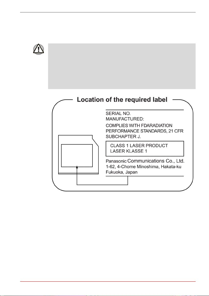
Panasonic
DVD Super Multi UJ-852M/852B
■ The DVD Super Multi drive employs a laser system. To ensure proper
use of this product, please read this instruction manual carefully and
retain for future reference. Should the unit ever require maintenance,
contact an authorized service location.
■ Use of controls, adjustments or the performance of procedures other
than those specified may result in hazardous radiation exposure.
■ To prevent direct exposure to the laser beam, do not try to open the
enclosure.
U300 Series
User’s Manual v
Page 6
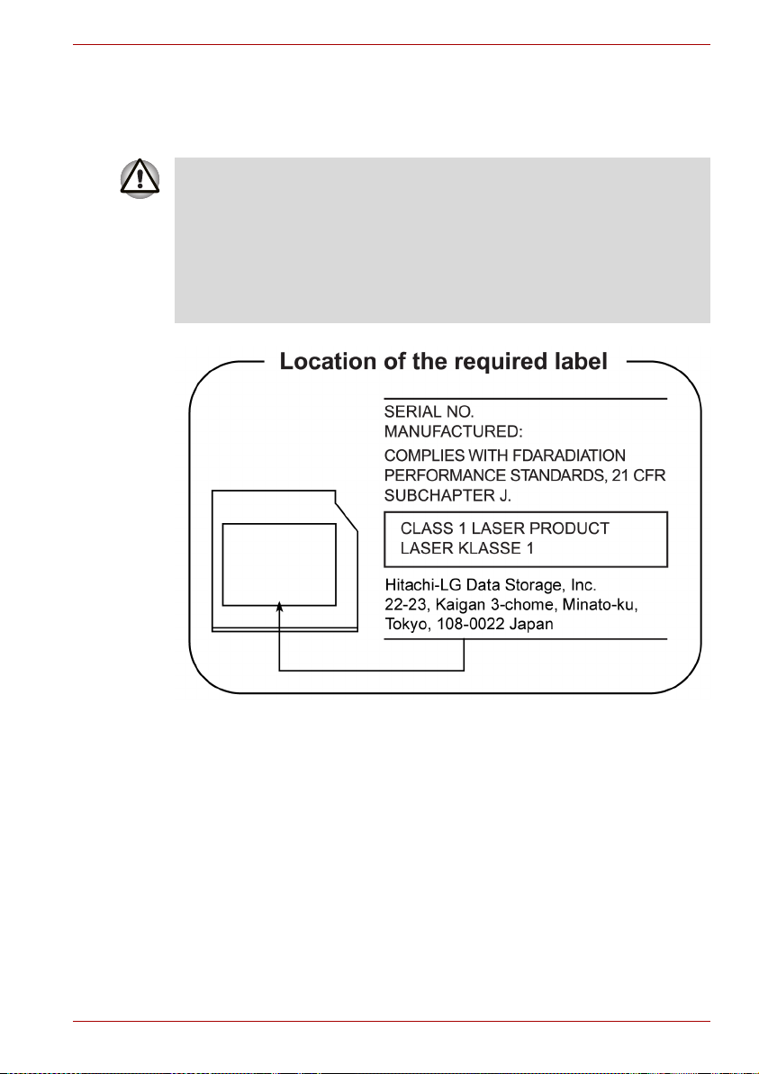
HLDS
DVD Super Multi GSA-U10N
■ The DVD Super Multi drive employs a laser system. To ensure proper
use of this product, please read this instruction manual carefully and
retain for future reference. Should the unit ever require maintenance,
contact an authorized service location.
■ Use of controls, adjustments or the performance of procedures other
than those specified may result in hazardous radiation exposure.
■ To prevent direct exposure to the laser beam, do not try to open the
enclosure.
U300 Series
User’s Manual vi
Page 7

International Precautions
U300 Series
CAUTION: This appliance contains a laser
system and is classified as a "CLASS 1
LASER PRODUCT." To use this model
properly, read the instruction manual
carefully and keep this manual for your
future reference. In case of any trouble
with this model, please contact your
nearest "AUTHORIZED service station."
To prevent direct exposure to the laser
beam, do not try to open the enclosure.
CAUTION: USE OF CONTROLS OR
ADJUSTMENTS OR PERFORMANCE OF
PROCEDURES OTHER THAN THOSE
SPECIFIED IN THE OWNER’S MANUAL
MAY RESULT IN HAZARDOUS
RADIATION EXPOSURE.
User’s Manual vii
Page 8

General Precautions
TOSHIBA computers are designed to optimize safety, minimize strain and
withstand the rigors of portability. However, certain precautions should be
observed to further reduce the risk of personal injury or damage to the
computer.
Be certain to read the general precautions below and to note the cautions
included in the text of the manual.
Creating a computer-friendly environment
Place the computer on a flat surface that is large enough for the computer
and any other items you are using, such as a printer.
Leave enough space around the computer and other equipment to provide
adequate ventilation. Otherwise, they may overheat.
To keep your computer in prime operating condition, protect your work area
from:
■ Dust, moisture, and direct sunlight.
■ Equipment that generates a strong electromagnetic field, such as
stereo speakers (other than speakers that are connected to the
computer) or speakerphones.
■ Rapid changes in temperature or humidity and sources of temperature
change such as air conditioner vents or heaters.
■ Extreme heat, cold, or humidity.
■ Liquids and corrosive chemicals.
U300 Series
Stress injury
Carefully read the Instruction Manual for Safety and Comfort. It contains
information on the prevention of stress injuries to your hands and wrists
that can be caused by extensive keyboard use. Chapter 3, Getting Started,
also includes information on work space design, posture and lighting that
can help reduce physical stress.
User’s Manual viii
Page 9

Heat injury
■ Avoid prolonged physical contact with the computer. If the computer is
used for long periods, its surface can become very warm. While the
temperature will not feel hot to the touch, if you maintain physical
contact with the computer for a long time, for example if you rest the
computer on your lap or if you keep your hands on the palm rest, your
skin might suffer a low-heat injury.
■ If the computer has been used for a long time, avoid direct contact with
the metal plate supporting the various interface ports as this can
become hot.
■ The surface of the AC adaptor can become hot when in use but this
condition does not indicate a malfunction. If you need to transport the
AC adaptor, you should disconnect it and let it cool before moving it.
■ Do not lay the AC adaptor on a material that is sensitive to heat as the
material could become damaged.
Pressure or impact damage
Do not apply heavy pressure to the computer or subject it to any form of
strong impact as this can damage the computer's components or otherwise
cause it to malfunction.
Express Card overheating
Some Express Cards can become hot during prolonged use which may
result in errors or instability in the operation of the device in question. In
addition, you should also be careful when you remove a Express Card that
has been used for a long time.
U300 Series
Mobile phones
Please be aware that the use of mobile phones can interfere with the audio
system. The operation of the computer will not be impaired in any way, but
it is recommended that a minimum distance of 30 cm is maintained
between the computer and a mobile phone that is in use.
Instruction Manual for Safety and Comfort
All important information on the safe and proper use of this computer is
described in the enclosed Instruction Manual for Safety and Comfort. Be
sure to read it before using the computer.
User’s Manual ix
Page 10

Table of Contents
Chapter 1 Introduction
Equipment checklist. . . . . . . . . . . . . . . . . . . . . . . . . . . . . . . . . . . . . . . 1-1
Features. . . . . . . . . . . . . . . . . . . . . . . . . . . . . . . . . . . . . . . . . . . . . . . . . 1-2
Special features . . . . . . . . . . . . . . . . . . . . . . . . . . . . . . . . . . . . . . . . . . 1-7
Utilities. . . . . . . . . . . . . . . . . . . . . . . . . . . . . . . . . . . . . . . . . . . . . . . . . . 1-9
Options . . . . . . . . . . . . . . . . . . . . . . . . . . . . . . . . . . . . . . . . . . . . . . . . 1-11
Chapter 2 The Grand Tour
Front with the display closed . . . . . . . . . . . . . . . . . . . . . . . . . . . . . . . 2-1
Left side. . . . . . . . . . . . . . . . . . . . . . . . . . . . . . . . . . . . . . . . . . . . . . . . . 2-2
Right side . . . . . . . . . . . . . . . . . . . . . . . . . . . . . . . . . . . . . . . . . . . . . . . 2-3
Backside . . . . . . . . . . . . . . . . . . . . . . . . . . . . . . . . . . . . . . . . . . . . . . . . 2-5
Underside . . . . . . . . . . . . . . . . . . . . . . . . . . . . . . . . . . . . . . . . . . . . . . . 2-5
Front with the display open. . . . . . . . . . . . . . . . . . . . . . . . . . . . . . . . . 2-6
Fixed optical media drives. . . . . . . . . . . . . . . . . . . . . . . . . . . . . . . . . . 2-8
AC adaptor . . . . . . . . . . . . . . . . . . . . . . . . . . . . . . . . . . . . . . . . . . . . . 2-10
U300 Series
Chapter 3 Getting Started
Installing the battery pack . . . . . . . . . . . . . . . . . . . . . . . . . . . . . . . . . . 3-1
Connecting the AC adaptor . . . . . . . . . . . . . . . . . . . . . . . . . . . . . . . . . 3-2
Opening the display . . . . . . . . . . . . . . . . . . . . . . . . . . . . . . . . . . . . . . . 3-4
Turning on the power . . . . . . . . . . . . . . . . . . . . . . . . . . . . . . . . . . . . . . 3-4
Start up for the first time . . . . . . . . . . . . . . . . . . . . . . . . . . . . . . . . . . . 3-5
Turning off the power . . . . . . . . . . . . . . . . . . . . . . . . . . . . . . . . . . . . . . 3-5
Restarting the computer . . . . . . . . . . . . . . . . . . . . . . . . . . . . . . . . . . . 3-8
Restoring the preinstalled software . . . . . . . . . . . . . . . . . . . . . . . . . . 3-8
User’s Manual x
Page 11

U300 Series
Chapter 4
Operating Basics
Using the TouchPad . . . . . . . . . . . . . . . . . . . . . . . . . . . . . . . . . . . . . . . 4-1
Using the Web Camera (depends on the model purchased) . . . . . . 4-2
Using the microphone . . . . . . . . . . . . . . . . . . . . . . . . . . . . . . . . . . . . . 4-4
Using the optical media drive . . . . . . . . . . . . . . . . . . . . . . . . . . . . . . . 4-4
Writing CD/DVDs with the DVD Super Multi drive
supporting DVD±R Double layer . . . . . . . . . . . . . . . . . . . . . . . . . . . . . 4-9
TOSHIBA Disc Creator . . . . . . . . . . . . . . . . . . . . . . . . . . . . . . . . . . . . 4-12
Media care . . . . . . . . . . . . . . . . . . . . . . . . . . . . . . . . . . . . . . . . . . . . . . 4-13
Modem . . . . . . . . . . . . . . . . . . . . . . . . . . . . . . . . . . . . . . . . . . . . . . . . . 4-14
Wireless communications . . . . . . . . . . . . . . . . . . . . . . . . . . . . . . . . . 4-17
LAN . . . . . . . . . . . . . . . . . . . . . . . . . . . . . . . . . . . . . . . . . . . . . . . . . . . 4-19
Cleaning the computer. . . . . . . . . . . . . . . . . . . . . . . . . . . . . . . . . . . . 4-20
Moving the computer . . . . . . . . . . . . . . . . . . . . . . . . . . . . . . . . . . . . . 4-21
Using the Hard Disk Drive (HDD) Protection . . . . . . . . . . . . . . . . . . 4-22
Chapter 5 The Keyboard
Typewriter keys. . . . . . . . . . . . . . . . . . . . . . . . . . . . . . . . . . . . . . . . . . . 5-1
F1 … F12 function keys . . . . . . . . . . . . . . . . . . . . . . . . . . . . . . . . . . . . 5-2
Soft keys: Fn key combinations . . . . . . . . . . . . . . . . . . . . . . . . . . . . . 5-2
Hot keys. . . . . . . . . . . . . . . . . . . . . . . . . . . . . . . . . . . . . . . . . . . . . . . . . 5-3
Windows® special keys. . . . . . . . . . . . . . . . . . . . . . . . . . . . . . . . . . . . 5-5
Keypad overlay . . . . . . . . . . . . . . . . . . . . . . . . . . . . . . . . . . . . . . . . . . . 5-5
Generating ASCII characters. . . . . . . . . . . . . . . . . . . . . . . . . . . . . . . . 5-6
Chapter 6 Power and Power-Up Modes
Power conditions . . . . . . . . . . . . . . . . . . . . . . . . . . . . . . . . . . . . . . . . . 6-1
Power indicators. . . . . . . . . . . . . . . . . . . . . . . . . . . . . . . . . . . . . . . . . . 6-2
Battery types. . . . . . . . . . . . . . . . . . . . . . . . . . . . . . . . . . . . . . . . . . . . . 6-2
Care and use of the battery pack . . . . . . . . . . . . . . . . . . . . . . . . . . . . 6-4
Replacing the battery pack . . . . . . . . . . . . . . . . . . . . . . . . . . . . . . . . 6-10
Starting the computer by password . . . . . . . . . . . . . . . . . . . . . . . . . 6-12
Power-up modes. . . . . . . . . . . . . . . . . . . . . . . . . . . . . . . . . . . . . . . . . 6-12
Panel power off/on . . . . . . . . . . . . . . . . . . . . . . . . . . . . . . . . . . . . . . . 6-13
System Auto Off . . . . . . . . . . . . . . . . . . . . . . . . . . . . . . . . . . . . . . . . . 6-13
Chapter 7 HW Setup
Accessing HW Setup . . . . . . . . . . . . . . . . . . . . . . . . . . . . . . . . . . . . . . 7-1
HW Setup Window . . . . . . . . . . . . . . . . . . . . . . . . . . . . . . . . . . . . . . . . 7-1
User’s Manual xi
Page 12

U300 Series
Chapter 8
Optional Devices
Express Card . . . . . . . . . . . . . . . . . . . . . . . . . . . . . . . . . . . . . . . . . . . . 8-1
SD/MMC/MS/MS Pro/xD Memory cards . . . . . . . . . . . . . . . . . . . . . . . 8-3
Memory expansion . . . . . . . . . . . . . . . . . . . . . . . . . . . . . . . . . . . . . . . . 8-6
Additional battery pack . . . . . . . . . . . . . . . . . . . . . . . . . . . . . . . . . . . . 8-9
Additional AC adaptor . . . . . . . . . . . . . . . . . . . . . . . . . . . . . . . . . . . . . 8-9
External monitor . . . . . . . . . . . . . . . . . . . . . . . . . . . . . . . . . . . . . . . . . 8-10
Security lock . . . . . . . . . . . . . . . . . . . . . . . . . . . . . . . . . . . . . . . . . . . . 8-10
Chapter 9 Troubleshooting
Problem solving process. . . . . . . . . . . . . . . . . . . . . . . . . . . . . . . . . . . 9-1
Hardware and system checklist . . . . . . . . . . . . . . . . . . . . . . . . . . . . . 9-3
TOSHIBA support . . . . . . . . . . . . . . . . . . . . . . . . . . . . . . . . . . . . . . . . 9-14
Appendix A Specifications
Appendix B Display Controller and Modes
Appendix C Wireless LAN
Appendix D AC Power Cord and Connectors
Appendix E Legal Footnotes
Appendix F If your computer is stolen
Glossary
Index
User’s Manual xii
Page 13

Preface
Congratulations on your purchase of the TOSHIBA U300 Series computer.
This powerful notebook computer provides excellent expansion capability,
including multimedia devices, and it is designed to provide years of reliable,
high-performance computing.
This manual tells how to set up and begin using your TOSHIBA U300
Series computer. It also provides detailed information on configuring your
computer, basic operations and care, using optional devices and
troubleshooting.
If you are a new user of computers or if you’re new to portable computing,
first read over the Introduction and The Grand Tour chapters to familiarize
yourself with the computer's features, components and accessory devices.
Then read Getting Started for step-by-step instructions on setting up your
computer.
If you are an experienced computer user, please continue reading the
preface to learn how this manual is organized, then become acquainted
with this manual by browsing through its pages. Be sure to look over the
Specifications section of the Introduction, to learn about features that are
uncommon or unique to the computer. If you are going to install PC Cards
or connect external devices such as a monitor, be sure to read Chapter 8,
Optional Devices.
U300 Series
Manual contents
This manual is composed of the following nine chapters, six appendixes, a
glossary and an index.
Chapter 1, Introduction, is an overview of the computer's features,
capabilities, and options.
Chapter 2, The Grand Tour, identifies the components of the computer and
briefly explains how they function.
Chapter 3, Getting Started, provides a quick overview of how to begin
operating your computer and gives tips on safety and designing your work
area.
Chapter 4, Operating Basics, includes instructions on using the following
devices: TouchPad, Sound System, optical media drives, modem, wireless
communication and LAN. It also provides tips on care of the computer, and
CD/DVDs.
User’s Manual xiii
Page 14

Chapter 5, The Keyboard, describes special keyboard functions including
the keypad overlay and hot keys.
Chapter 6, Power and Power-Up Modes, gives details on the computer's
power resources and battery save modes.
Chapter 7, HW Setup explains how to configure the computer using the
HW Setup program.
Chapter 8, Optional Devices, describes the optional hardware available.
Chapter 9, Troubleshooting, provides helpful information on how to perform
some diagnostic tests, and suggests courses of action if the computer
doesn’t seem to be working properly.
The Appendices provide technical information about your computer.
The Glossary defines general computer terminology and includes a list of
acronyms used in the text.
The Index quickly directs you to the information contained in this manual.
Conventions
This manual uses the following formats to describe, identify, and highlight
terms and operating procedures.
Abbreviations
On first appearance, and whenever necessary for clarity, abbreviations are
enclosed in parentheses following their definition. For example: Read Only
Memory (ROM). Acronyms are also defined in the Glossary.
U300 Series
Icons
Icons identify ports, dials, and other parts of your computer. The indicator
panel also uses icons to identify the components it is providing information on.
Keys
The keyboard keys are used in the text to describe many computer
operations. A distinctive typeface identifies the key top symbols as they
appear on the keyboard. For example, Enter identifies the Enter key.
Key operation
Some operations require you to simultaneously use two or more keys. We
identify such operations by the key top symbols separated by a plus
sign (+). For example, Ctrl + C means you must hold down Ctrl and at the
same time press C. If three keys are used, hold down the first two and at
the same time press the third.
ABC When procedures require an action such as
clicking an icon or entering text, the icon’s name
or the text you are to type in is represented in the
type face you see to the left.
User’s Manual xiv
Page 15

Display
U300 Series
ABC
Names of windows or icons or text generated by
the computer that appears on its display screen is
presented in the type face you see to the left.
Messages
Messages are used in this manual to bring important information to your
attention. Each type of message is identified as shown below.
Pay attention! A caution informs you that improper use of equipment or
failure to follow instructions may cause data loss or damage your
equipment.
Please read. A note is a hint or advice that helps you make best use of
your equipment.
Indicates a potentially hazardous situation, which could result in death or
serious injury, if you do not follow instructions.
User’s Manual xv
Page 16

Introduction
This chapter provides an equipment checklist, and it identifies the
computer's features, options and accessories.
Some of the features described in this manual may not function properly if
you use an operating system that was not pre-installed by TOSHIBA.
Equipment checklist
Carefully unpack your computer. Save the box and packing materials for
future use.
Hardware
Check to make sure you have all the following items:
■ TOSHIBA U300 Series Portable Personal Computer
■ Universal AC adaptor and power cord
■ Battery pack (Installed or separate from the computer)
It is necessary to install the battery to use this computer. Refer to Installing
the battery pack section in Chapter 3, Getting Started.
Introduction
Chapter 1
Software
Microsoft® Windows® XP Home Edition/Professional
The following software is preinstalled:
■ Microsoft
■ Microsoft Internet Explorer
■ TOSHIBA Utilities
■ TOSHIBA Hardware Setup
■ TOSHIBA Supervisor Password
■ TOSHIBA Assist
■ TOSHIBA ConfigFree
■ DVD Video Player
User’s Manual 1-1
®
Windows® XP Home Editon/Professional
Page 17

■ TOSHIBA CD/DVD Acoustic Silencer
■ TOSHIBA SD Utilities
■ TOSHIBA Disc Creator
■ Display Driver
■ TouchPad Driver
■ Sound Driver
■ Miscellaneous drivers (depending on the model you purchased:
Modem, Wireless LAN)
Documentation
■ U300 Series Personal Computer User´s Manual
■ U300 Series Quickstart
®
■ Microsoft
Windows® XP manual package (Provided with some
models)
■ Instruction Manual for Safety and Comfort
■ Warranty Information
Backup media and additional Software
■ Product Recovery DVD-ROM
If any of the items are missing or damaged, contact your dealer
immediately.
Introduction
Features
Please visit your region’s web site for the configuration details of the model
that you have purchased.
Processor
Built-in Depend on the model you purchased.
Intel® Core™ 2 Duo Processor
®
Core™ Duo Processor
Intel
Intel® Pentium® Dual Core Processor
®
Celeron® M Processor
Intel
TJ85 Seam CPU support
®
Chipset Mobile Intel
Mobile Intel® 945GM Express Chipset
Mobile Intel
User’s Manual 1-2
GM965 Express Chipset
®
943GML Express Chipset
Page 18

Memory
Introduction
Main Memory
Disclaimer
Part of the main system memory may be used by
the graphics system for graphics performance
and therefore reduce the amount of main system
memory available for other computing activities.
The amount of main system memory allocated to
support graphics may vary depending on the
graphics system, applications utilized, system
memory size and other factors. For PC's
configured with 4 GB of system memory, the full
system memory space for computing activities will
be considerably less and will vary by model and
system configuration.
Slots Up to two 2048 MB memory modules can be
installed in the memory slot for a maximum of
4 GB system memory total.
Video RAM Depending on the model you purchased:
Mobile Intel
®
GM965/GL960/945GM/943GML
Express Chipset, up to 251 MB shared with main
memory.
(for more than 1 GB main memory)
Power
Battery Pack Your computer is powered by a rechargeable
RTC Battery The internal RTC battery backs up the Real Time
AC Adaptor The universal AC adaptor provides power to the
lithium-ion battery pack.
Clock and calendar.
system and recharges the batteries when they
are low. It comes with a detachable power cord.
Because it is universal, it can receive a range of
AC voltage from 100 to 240 volts; however, the
output current varies among different models.
Using the wrong model can damage your
computer. Refer to the AC adaptor section in
Chapter 2, The Grand Tour.
User’s Manual 1-3
Page 19

Disks
Introduction
Hard disk Disclaimer 1 Gigabyte (GB) means 109 =
1,000,000,000 bytes using powers of 10. The
computer operating system, however, reports
storage capacity using powers of 2 for the
definition of 1 GB = 230 = 1,073,741,824 bytes,
and therefore shows less storage capacity.
Available storage capacity will also be less if the
product includes one or more pre-installed
operating systems, such as Microsoft Operating
System and/or pre-installed software applications,
or media content. Actual formatted capacity may
vary.
Hard disk Drive Available in five sizes.
■ 80.0 billion bytes (74.51 GB)
■ 120.0 billion bytes (111.75 GB)
■ 160.0 billion bytes (149.01 GB)
■ 200.0 billion bytes (186.26 GB)
Other hard disk drives may be introduced in the
future.
Computers in this series can be configured with a fixed optical media drive.
The available optical media drives are described below.
User’s Manual 1-4
Page 20

Introduction
DVD Super Multi drive
(Supporting DVD±R
Double Layer)
Some models are equipped with a full-size
DVD Super Multi drive module that lets you
record data to rewritable CD/DVDs as well as run
either 12 cm (4.72") or 8 cm (3.15") CD/DVDs
without using an adaptor. It reads DVD-ROM's at
maximum 8 speed and CD-ROM's at maximum
24 speed. It writes CD-R's at up to 24 speed,
CD-RW's at up to 16 speed, DVD-R's at
maximum 8 speed, DVD-RW's at maximum
6 speed. DVD+R's at maximum 8 speed,
DVD+RW's at maximum 8 speed, DVD+R(DL)
discs at maximum 4 speed and DVD-R(DL) discs
at maximun 4 speed.
DVD-RAM at maximum 5 speed. This drive
supports the following formats in addition to
DVD-ROM & CD-R/RW drive.
■ DVD+R
■ DVD+RW
■ DVD-RAM
■ DVD-R
■ DVD-RW
■ DVD+R (DL)
■ DVD-R (DL)
Display
The computer's LCD panel supports high-resolution video graphics. The
screen can be set at a wide range of viewing angles for maximum comfort
and readability.
Built-In 13.3" WXGA 16 million colors, with the following
Graphics Controller Graphics controller maximizes display
resolution:
1280 horizontal × 800 vertical pixels
performance. Refer to Display Controller and
Modes section in Appendix B, Display Controller
and Modes for more information.
Keyboard
Built-In Between 84 keys and 87 keys, compatible with
IBM enhanced keyboard, embedded numeric
overlay, dedicated cursor control, and
keys. Refer to Chapter 5, The Keyboard, for
details.
User’s Manual 1-5
Page 21

Pointing Device
Introduction
Built-In TouchPad A TouchPad and control buttons in the palm rest
enable control of the on-screen pointer and
scrolling of windows.
Ports
External Monitor Depending on the model you purchased:
15-pin, analog VGA port supports VESA DDC2B
compatible functions.
Universal Serial Bus
(USB 2.0)
i.LINK (IEEE1394a) This port enables high-speed data transfer
The computer has Universal Serial Bus ports that
comply with the USB 2.0 standard, which enables
data transfer speeds 40 times faster than
the USB 1.1 standard. (The ports also support
USB 1.1.)
directly from external devices such as digital
video cameras.
Slots
Express Card The Express Card expansion slot that can
accommodate two standard module formats;
an Express Card/34 module and an Express
Card/54 module. An Express Card module is a
small add-in card technology based on the PCI
Express and Universal Serial Bus (USB)
interfaces.
(Depends on the model purchased.)
Multiple Digital
Media Card Slot
Supports SD, Mini SD(with adaptor), MMS, MS,
MS Pro, xD cards.
Multimedia
Web Camera Record/Send still or video images with this
integrated webcam.
(Depends on the model purchased.)
Sound System A Windows
speakers as well as jacks for an external
microphone and headphones.
Headphone Jack This jack outputs analog audio signals.
Microphone Jack A 3.5 mm mini microphone jack enables
connection of a three-conductor mini jack for
monaural microphone input.
User’s Manual 1-6
®
Sound System that provides
Page 22

Communications
Introduction
Modem The internal modem provides capability for data
LAN The computer has built-in support for Ethernet
Wireless LAN The Wireless LAN feature is not available on all
Security
Password Power-on password protection.
Special features
The following features are either unique to TOSHIBA computers or are
advanced features, which make the computer more convenient to use.
Hot Keys Key combinations let you quickly modify the
Keypad Overlay A ten-key pad is integrated into the keyboard.
Instant Security The hot key function Fn + F1 blanks the screen
and fax communication. It supports V.90 (V.92).
The speed of data transfer and fax depends on
analog telephone line conditions. It has a modem
jack for connecting to a teleohone line. It is
preinstalled as a standard device in some
markets. Both V.90 and V.92 are supported only
in the USA, Canada, U.K., France, Germany and
Australia. V.90 is available in other regions.
LAN (10 megabits per second, 10BASE-T) and
Fast Ethernet LAN (100 megabits per second,
100BASE-TX).
models. Where present, it supports the A,B,G and
N standards but it is compatible with other LAN
systems based on Direct Sequence Spread
Spectrum/Orthogonal Frequency Division
Multiplexing radio technology that complies with
the IEEE 802.11 Standard.
Two level password architecture.
system configuration directly from the keyboard
without running a system configuration program.
Refer to the Keypad overlay section in Chapter 5,
The Keyboard, for instructions on using the
keypad overlay.
and disables the computer, providing data
security.
User’s Manual 1-7
Page 23

Introduction
Display Automatic
Power Off
HDD Automatic
Power Off
*1
*1
System Automatic
Standby Mode/
Hibernation
Intelligent Power
Supply
*1
*1
Battery Save Mode
Panel Power On/Off
Low Battery
Automatic
Hibernation
*1
TOSHIBA HDD
Protection
This feature automatically cuts off power to the
internal display when there is no keyboard input
for a specified time. Power is restored when any
key is pressed.
This can be specified in the Power Options.
This feature automatically cuts off power to the
hard disc drive when it is not accessed for a
specified time. Power is restored when the hard
disc is accessed.
This can be specified in the Power Options.
This feature automatically shuts down the system
into Standby Mode or Hibernation Mode when
there is no input or hardware access for a
specified time.
This can be specified in the Power Options.
A microprocessor in the computer's intelligent
power supply detects the battery’s charge and
calculates the remaining battery capacity. It also
protects electronic components from abnormal
conditions, such as voltage overload from an
AC adaptor.
This can be specified in the Power Options.
*1
This feature lets you save battery power.
This can be specified in the Power Options.
*1
This feature turns power to the computer off when
the display panel is closed and turns it back on
when the panel is opened.
This can be specified in the Power Options.
When battery power is exhausted to the point that
computer operation cannot be continued, the
system automatically enters Hibernation Mode
and shuts down.
This can be specified in the Power Options.
This feature uses the acceleration sensor built in
the computer to detect vibration and shocks, and
automatically moves the hard disk drive's read/
write head to a safe position in order to reduce the
risk of damage that could be caused by headtodisk contact. Refer to the Using the Hard Disk
Drive (HDD) Protection section in Chapter 4,
Operating Basics, for more details.
The TOSHIBA HDD Protection function does not guarantee that the hard
disk drive will not be damaged.
User’s Manual 1-8
Page 24

Introduction
Utilities
Hibernation This feature lets you turn off the power without
Standby Mode If you have to interrupt your work, you can turn off
*1 Click Start, Control Panel, Performance and Maintenance, Power
Options and Alarm tab.
This section describes preinstalled utilities and tells how to start them. For
details on operations, refer to each utility’s online manual, help files or
readme.txt files.
TOSHIBA Power
Saver
TOSHIBA Zooming
Utility
TOSHIBA PC
Diagnostic Tool
TOSHIBA
Accessibility
exiting from your software. The contents of main
memory are saved to the hard disk so that when
you turn on the power again, you can continue
working right where you left off. Refer to the
Turning off the power section in Chapter 3,
Getting Started, for details.
the power without exiting from your software.
Data is maintained in the computer's main
memory so that when you turn on the power
again, you can continue working right where you
left off.
TOSHIBA Power Saver provides you with the
features of more various power supply
managements.
This utility allows you to enlarge or reduce the
icon size on the desktop or the application
window.
To run TOSHIBA Zooming Utility, click Start,
select All Programs followed by TOSHIBA
followed by Utilities and then click Zooming
Utility.
TOSHIBA PC Diagnostic Tool displays the basic
information on the computer's configuration and
allows some of the built-in devices functionality to
be tested. To start the TOSHIBA PC Diagnostic
Tool, click Start, point to All Programs, point to
TOSHIBA, and point to Utilities and click PC
Diagnostic Tool.
The TOSHIBA Accessibility utility provides
support to movement impaired users when they
need to use the TOSHIBA Hot-key functions. In
use, the utility allows you to make the Fn key
'sticky', that is you can press it once, release it,
and then press one of the 'F' keys in order to
access its specific function. When set, the Fn key
will remain active until another key is pressed.
User’s Manual 1-9
Page 25

Introduction
TOSHIBA Assist TOSHIBA Assist is a graphical user interface that
provides easy access to help and services.
HW Setup This program lets you customize your hardware
settings according to the way you work with your
computer and the peripherals you use. To start
the utility, double click the TOSHIBA Assist on
your desktop, select OPTIMIZE tab, and click
TOSHIBA Hardware Settings.
Power On Password Two levels of password security, supervisor and
user, are available to prevent unauthorized
access to your computer.
To register a supervisor password, double click
the TOSHIBA Assist on your desktop select the
SECURE tab and start the Supervisor password
utility.
To set a user password, select the SECURE tab
on TOSHIBA Assist, then start the User
password utility. On the Password tab you can
register a user password.
TOSHIBA DVD Player The DVD Video Player is used to play DVD Video.
It has an on-screen interface and functions. Click
Start, point to All Programs, point to InterVideo
WinDVD, then click InterVideo WinDVD.
TOSHIBA Disc
Creator
You can create CD/DVDs in several formats
including audio CDs that can be played on a
standard stereo CD player and data CDs or DVDs
to store multimedia and/or document files on your
hard disk drive. This software can be used on a
model with the CD-RW/DVD-ROM drive, DVD-R/
-RW drive, DVD±R/±RW drive and DVD Super
Multi drive.
To run TOSHIBA Disc Creator, click Start, select
All Programs, TOSHIBA, CD&DVD
Applications, and then click Disc Creator.
TOSHIBA ConfigFree ConfigFree is a suite of utilities to allow easy
control of communication device and network
connections. ConfigFree also allows you to find
communication problems and create profiles for
easy switching between location and
communication networks.
To run ConfigFree, click Start, select All
Programs followed by TOSHIBA followed by
Networking and then click ConfigFree.
TOSHIBA TouchPad
On/Off Utility
Pressing Fn + F9 enables or disables the
TouchPad function. When you press these hot
keys, the current setting will change and be
displayed as an icon.
User’s Manual 1-10
Page 26

Options
Introduction
You can add a number of options to make your computer even more
powerful and convenient to use. Refer to Chapter 8 Optional Devices, for
details. The following options are available:
Memory expansion Two memory modules can be installed in this
computer.
Use only PC5300* compatible DDRII memory modules. See your
TOSHIBA dealer for details.
* The availability of DDRII depends on the model you purchased.
Battery pack An additional battery pack can be purchased from
your TOSHIBA dealer. Use it as a spare to
increase your computer operating time.
AC Adaptor If you use your computer at more than one site
frequently, it may be convenient to purchase an
additional AC adaptor for each site so you will not
have to carry the adaptor with you.
User’s Manual 1-11
Page 27
The Grand Tour
This chapter identifies the various components of your computer. Become
familiar with each component before you operate the computer.
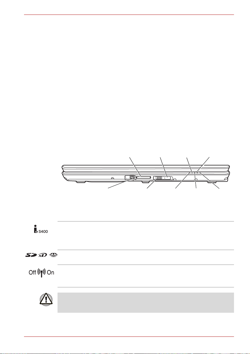
Front with the display closed
The following figure shows the computer's front with its display panel in the
closed position.
Multiple Digital
Media Card Slot
Chapter 2
Wireless
Activity LED
Power
LED
The Grand Tour
Hard Disk
Drive LED
i.LINK
(IEEE 1394a) Port
Front of the computer with display closed
i.LINK (IEEE1394a)
Port
Wireless
Communication
Switch
DC in
LED
This port allows you to connect an external
device, such as a digital video camera, for
Battery
LED
Multiple
Digital Media
Card Slot
LED
highspeed data transfer.
(Depends on the model you purchased.)
Multiple Digital Media
Card Slot
Wireless
Communication
Switch
Supports SD, mini SD (thru adaptor), MMS, MS,
MS PRO, xD media cards.
The Wireless Communication Switch turns on the
wireless networking transceiver.
(Depends on the model you purchased.)
Set the switch to off in airplanes and hospitals. Check the wireless activity
indicator. It will stop glowing when the wireless communication function is
off.
User’s Manual 2-1
Page 28
The Grand Tour
Wireless Activity LED Indicates whether the wireless LAN or Bluetooth
is active or not.
(Depends on the model you purchased.)
DC IN LED The DC IN LED indicates the computer is
connected to the AC adaptor and it is plugged into
an AC power source.
Power LED The Power indicator glows blue when the
computer is on. If you select Standby Mode from
Turn Off Computer, this indicator flashes orange
(one second on, two seconds off) while the
computer enters Standby Mode.
Battery LED The Battery indicator shows the condition of the
battery's charge: Blue indicates a full charge,
orange indicates that the battery is charging and
flashing orange indicates a low battery charge.
Refer to Chapter 6, Power and Power-Up Modes.
Hard Disk Drive LED The Hard Disk Drive LED indicates that the hard
disk drive is being accessed. Every time your
computer runs a program, opens a file, or
performs some other function in which it must
access the hard disk drive, this light will go on.
Multiple Digital Media
Card Slot LED
Multiple Digital Media Card Slot LED lights up
when the Multiple Digital Media Card Slot is
accessed.
(Depends on the model you purchased.)
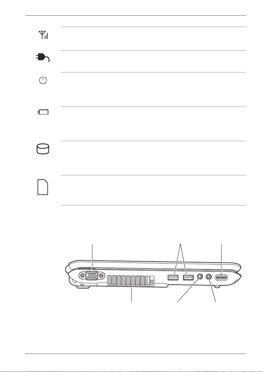
Left side
The following figure shows the computer's left side.
External Monitor Port
Cooling Vents
The left side of the computer
User’s Manual 2-2
USB Ports
Microphone
Jack
Volume Dial
Headphone
Jack
Page 29
The Grand Tour
External Monitor Port This 15-pin port lets you connect an external
video display. The Analog VGA port supports
VESA DDC2B compatible functions.
(Depends on the model you purchased.)
Cooling Vents Cooling vents help prevent the CPU from
overheating.
Do not block the cooling vents. Also ensure that foreign objects are kept
out of the vents as items such as pins or similar objects, which can
damage the computer's circuitry.
Universal Serial Bus
(USB 2.0) ports
Two Universal Serial Bus ports are on the left
side. The ports comply with the USB 2.0
standard, which enable data transfer speeds
40 times faster than the USB 1.1 standard
(The ports also support USB 1.1). Keep foreign
objects out of the USB connectors. A pin or
similar object can damage the computer's
circuitry. Operation of all functions of all USB
devices has not been confirmed. As such, some
untested third-party devices may not function
properly.
Microphone Jack A 3.5 mm mini microphone jack enables
connection of a three-conductor mini jack for
monaural microphone input.
Headphone Jack This jack outputs analog audio signals.
Volu m e D i a l Use this dial to adjust the volume of the stereo
speakers or headphones.
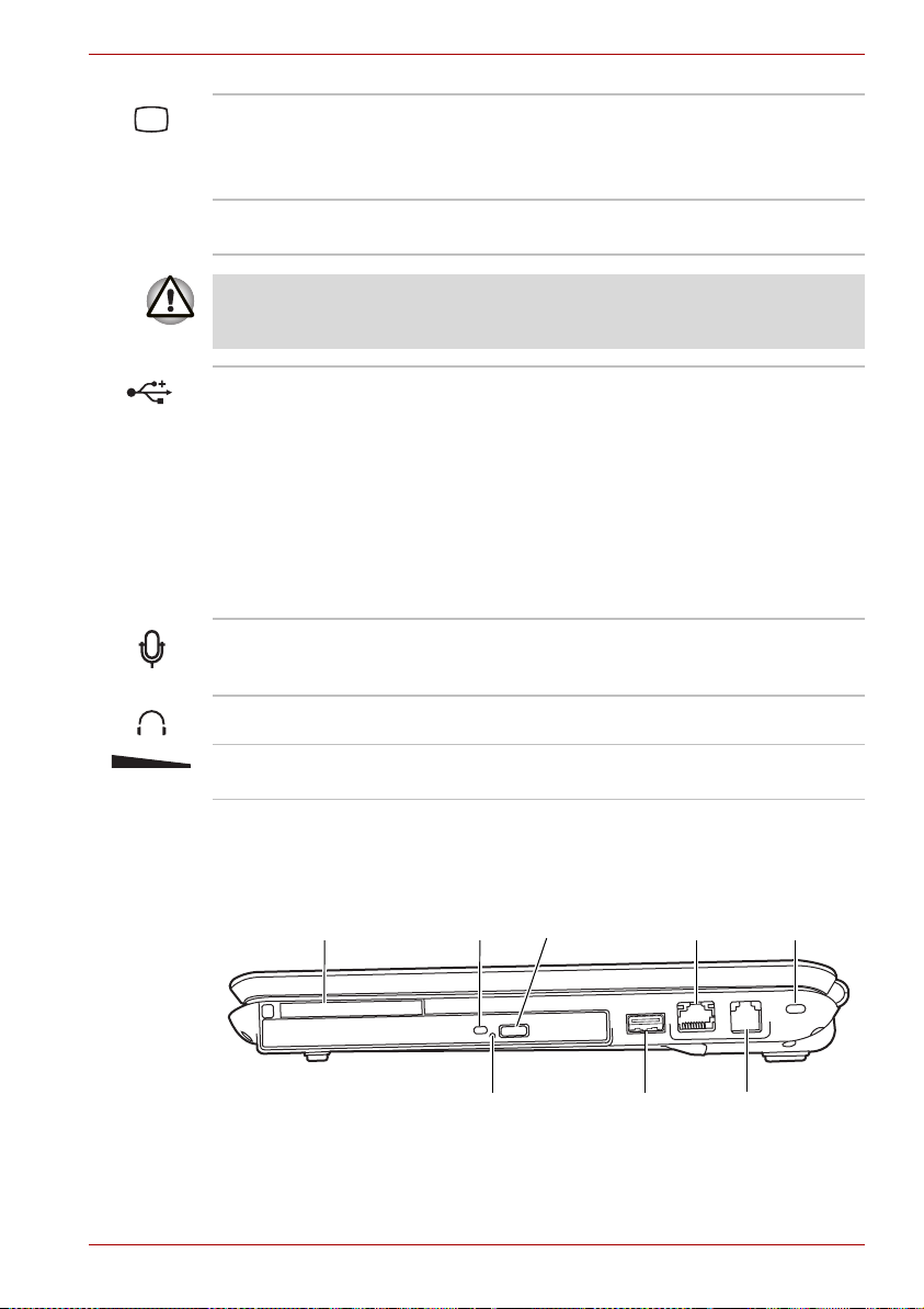
Right side
The following figure shows the computer's right side.
Express
Card Slot
User’s Manual 2-3
ODD
Indicator
Emergency
Eject Hole
The right side of the computer
Eject
Button
USB Port
LAN Jack
Modem
Jack
Security
Lock
Page 30
The Grand Tour
Express Card Slot for
Cardbus Card Slot
This slot allows you to insert an Express Card.
An Express Card is a small, modular add-in card
technology based on PCI Express and the
Universal Serial Bus (USB) interface. The max.
transmission rate is 2.5Gbps. Express Card/34
and Express Card/54 types are supported.
ODD Indicator The ODD indicator glows amber when the
computer accesses the optical disc drive.
Emergency Eject Hole In the event that the disc drive becomes
inexplicably locked or stops responding press this
button to force a manual ejection of the ODD tray.
Eject Button Press this button to open the ODD tray.
Universal Serial Bus
(USB 2.0) port
A single of Universal Serial Bus port is on the right
side. The port complies with the USB 2.0
standard, which enables data transfer speeds
40 times faster than the USB 1.1 standard
(The ports also support USB 1.1). Keep foreign
objects out of the USB connectors. A pin or
similar object can damage the computer's
circuitry. Operation of all functions for all USB
devices has not been confirmed. As such, some
untested third-party devices may not function
properly.
LAN Jack This jack lets you connect to a LAN. The adaptor
has built-in support for Ethernet LAN
(10 megabits per second, 10BASE-T) and Fast
Ethernet LAN (100 megabits per second,
100BASE-TX). Refer to Chapter 4, Operating
Basics, for details.
Modem Jack The modem jack allows you to use a modular
cable to connect the modem directly to a
telephone line.
(Depends on the model you purchased.)
■ In case of a lightning storm, unplug the
modem cable from the telephone jack.
■ Do not connect the modem to a digital
telephone line. A digital line will damage the
modem.
Security Lock A security cable attaches to this port. The optional
security cable anchors your computer to a desk or
other large object to deter theft.
User’s Manual 2-4
Page 31

Backside
The following figure shows the computer's back panel.
Underside
The following figure shows the underside of the computer. Make sure the
display is closed before turning over your computer.
The Grand Tour
DC in 19V Jack
The backside of the computer
DC IN 19V Jack The AC adaptor connects to this socket. Use only
the model of AC adaptor that comes with the
computer. Using the wrong adaptor can damage
your computer.
Battery Pack Battery Release Latch
Battery
Pack
Lock
Memory
Module
and
Wireless
LAN
Cover
Cooling
Vents
Hard Disk Cover
The underside of the computer
Memory Module and
Wireless LAN Cover
This cover protects two memory module sockets -
-one or two modules are pre-installed. Refer to
the Memory expansion section in Chapter 8,
Optional Devices.
Battery Pack Lock Slide this lock to prepare the battery pack for
removal.
User’s Manual 2-5
Page 32

The Grand Tour
Battery Pack The battery pack powers the computer when the
Battery Release Latch Slide and hold this latch to release the battery
Cooling Vents Cooling vents help prevent the CPU from
Hard Disk Cover This cover protects the hard disk.
Front with the display open
This section shows the front of the computer with the display open. Refer to
the appropriate illustration for details. To open the display, lift the front of the
display. Position the display at a comfortable viewing angle.
Web Camera LED
Display
Screen
AC adaptor is not connected. For detailed
information on the battery pack, refer to
Chapter 6, Power and Power-Up Modes.
pack for removal. For detailed information on
removing the battery pack, refer to Chapter 6,
Power and Power-Up Modes.
overheating.
Web Camera
Power Button
Internet Button
CD/DVD Button
Play/Pause Button
Stop Button
Previous Button
Next Button
Speaker
Speaker
TouchPad
Control
TouchPad
The front of the computer with the display open
Buttons
Speakers The speakers emit sound generated by your
software as well as audio alarms, such as low
battery condition, generated by the system.
User’s Manual 2-6
Page 33

The Grand Tour
Display Screen The LCD displays high-contrast text and graphics.
Refer to Appendix B, Display Controller and
Modes. When the computer operates on the
AC adaptor the display screen’s image will be
somewhat brighter than when it operates on
battery power. The lower brightness level is
intended to save battery power.
Web Camera LED Web Camera LED indicates web camera is
working or not.
(Depends on the model you purchased.)
Web Camera Take your picture or send your image to web
contacts.
(Depends on the model you purchased.)
Power Button Turns the computer on and off and puts it into
Hibernation mode and wakes it up from Standby
Mode.
Internet Button Press this button to launch an Internet browser. If
the computer’s power is off, you can press this
button to turn on the computer’s power and
launch the browser automatically in one step.
(Depends on the model you purchased.)
Presentation Button Press this button to switch Windows screen to
clone mode display. Default setting is "clone
mode display 1024 × 768" at internal and external
display. You can also set extended mode at
external display. Press again to switch external
display only.
(Depends on the model purchased.)
CD/DVD Button Pressing this button will launch an application
program that allows for playing of CDs or DVDs.
The application that is launched differs by model:
Windows Media Player/TOSHIBA DVD Player.
(Depends on the model purchased.)
TOSHIBA Assist
Button
Press this button to launch TOSHIBA Assist
application. If the computer’s power is off, you can
press this button to turn on the computer’s power
and launch the TOSHIBA Assist application
automatically in one step.
(Depends on the model purchased.)
Play/Pause Button Press this button to begin playing an audio CD, a
DVD movie or digital audio file. This button also
acts as a Pause button.
(Depends on the model purchased.)
User’s Manual 2-7
Page 34

Stop Button Stops playing of the CD, DVD or digital audio.
Previous Button Skips backwards to the previous track, chapter or
Next Button Skips forward to the next track, chapter or digital
TouchPad A TouchPad located in the centre of the palm rest
TouchPad Control
Buttons
Fixed optical media drives
One of the following optical media drives is installed in the computer, either
a CD-ROM drive or DVD-ROM&CD-R/RW drive or a DVD Super Multi
drive. An ATAPI interface controller is used for CD/DVD operation. When
the computer is accessing a CD/DVD, an indicator on the drive glows.
The Grand Tour
(Depends on the model purchased.)
digital file. Refer to Chapter 4, Operating Basics,
for details.
(Depends on the model purchased.)
file. Refer to Chapter 4, Operating Basics, for
details.
(Depends on the model purchased.)
is used to control the on-screen pointer.
These let you select menu items or manipulate
text and graphics designated by the on-screen
pointer. Refer to the Using the TouchPad section
in Chapter 4, Operating Basics.
Region codes for DVD drive and media
DVD-ROM&CD-R/RW drive and the DVD Super Multi drives and their
associated media are manufactured according to the specifications of six
marketing regions. When you purchase DVD-Video, make sure it matches
your drive, otherwise it will not play properly.
Code Region
1 Canada, United States
2 Japan, Europe, South Africa, Middle East
3 Southeast Asia, East Asia
4 Australia, New Zealand, Pacific Islands, Central
America, South America, Caribbean
5 Russia, Indian Subcontinent, Africa, North Korea,
Mongolia
6 China
User’s Manual 2-8
Page 35

Writable discs
This section describes the types of writable CD discs. Check the
specifications of your drive for the type of discs it can write. Use TOSHIBA
Disc Creator to write compact discs. Refer to Chapter 4, Operating Basics.
CDs
■ CD-R discs can be written only once. The recorded data cannot be
erased or changed.
■ CD-RW discs can be recorded more than once. Use either 1, 2, or
4 multi speed CD-RW discs or high-speed 4- to 10-speed discs. The
write speed of the ultra-speed CD-RW discs (Ultra-speed is available
on the DVD-ROM & CD-R/RW drive only) is a maximum of 24-speed.
Formats
The drives support the following formats:
■ DVD-ROM*
■ CD-DA
■ Photo CD™ (single/multi-session)
■ CD-ROM X A Mode 2 (Form1, Form2)
■ CD-R (Audio CD only)
■ DVD -Video*
■ CD-Text
■ CD-ROM Mode 1, Mode 2
■ Enhanced CD (CD-EXTRA)
■ CD-RW
* Not available on the CD-ROM drive.
The Grand Tour
DVD Super Multi drive (Supporting DVD±R Double Layer)
The full-size DVD Super Multi drive module lets you record data to writable
CD/DVDs as well as run either 12 cm (4.72") or 8 cm (3.15") CD/DVDs
without using an adaptor.
The read speed is slower at the centre of a disc and faster at the outer
edge.
DVD read 8 speed (maximum)
DVD-R write 8 speed (maximum)
DVD-RW write 6 speed (maximum)
DVD+R write 8 speed (maximum)
DVD+RW write 8 speed (maximum)
DVD-R(DL) write 4 speed (maximum)
DVD+R(DL) write 4 speed (maximum)
User’s Manual 2-9
Page 36

DVD-RAM write 5 speed (maximum)
CD read 24 speed (maximum)
CD-R write 24 speed (maximum)
CD-RW write 16 speed (maximum, Ultra-speed media)
AC adaptor
The AC adaptor converts AC power to DC power and reduces the voltage
supplied to the computer. It can automatically adjust to any voltage from
100 to 240 volts and to a frequency of either 50 or 60 hertz, enabling you to
use the computer in almost any country/region.
To recharge the battery, simply connect the AC adaptor to a power source
and the computer. Refer to Chapter 6, Power and Power-Up Modes, for
details.
The Grand Tour
The AC adaptor
■ Use only the AC adaptor that came with the computer or an equivalent
optional adaptor. Use of the wrong adaptor could damage your
computer. TOSHIBA assumes no liability for any damage in such case.
■ Use only the AC Adaptor supplied with your computer or an equivalent
adaptor that is compatible. Use of any incompatible adaptor or other
types of AC Adaptors may have a different voltage which could cause
damage to your computer, computer failure and/or possible data loss.
TOSHIBA assumes no liability for any damage, computer failure and/or
data loss caused by use of an incompatible adaptor.
Use only the AC adaptor supplied as an accessory. Other AC adaptors
have different voltage and terminal polarities and use of them may produce
heat and smoke or even result in fire or rupture.
User’s Manual 2-10
Page 37

Getting Started
This chapter provides basic information to get you started using your
computer. It covers the following topics:
Be sure also to read the Safety Instruction Manual. This guide, which is
included with the computer, explains product liability.
■ Installing the battery pack
■ Connecting the AC adaptor
■ Opening the display
■ Turning on the power
■ Starting up for the first time
■ Turning off the power
■ Restarting the computer
■ Restoring the preinstalled software
All users should be sure to read the section Starting up for the first time.
Getting Started
Chapter 3
Installing the battery pack
To install a battery, follow the steps below.
■ The battery pack is a lithium ion battery, which can explode if not
properly replaced, used, handled or disposed of. Dispose of the battery
as required by local ordinances or regulations. Use only batteries
recommended by TOSHIBA as replacements.
■ Do not touch the latch while holding the computer. Or you may get
injured by the dropped battery by unintentional release of the latch.
■ Please do not push the power button before installing the battery pack.
1. Turn the computer's power off.
2. Disconnect all cables connected to the computer.
3. Insert the battery pack. The Battery Release Latch clicks into place.
User’s Manual 3-1
Page 38

Getting Started
4. Secure the Battery Pack Lock to ensure the battery is locked into place.
Later, when you want to remove the battery you must disengage this
lock first.
Battery Release Latch
Battery
Pack Lock
Securing the battery pack
Refer to Removing the battery pack section in Chapter 5, Power and
Power-Up Modes,for removing the battery pack.
Connecting the AC adaptor
Attach the AC adaptor when you need to charge the battery or you want to
operate from AC power. It is also the fastest way to get started, because
the battery pack will need to be charged before you can operate from
battery power.
The AC adaptor can be connected to any power source supplying from
100 to 240 volts and 50 or 60 hertz. For details on using the AC adaptor to
charge the battery pack, refer to Chapter 5, Power and Power-Up Modes.
Use only the AC adaptor supplied as an accessory. Other AC adaptors
have different voltage and terminal polarities and use of them may produce
heat and smoke or even result in fire or rupture.
User’s Manual 3-2
Page 39

Getting Started
■ Use only the AC adaptor supplied with your computer or an equivalent
adaptor that is compatible. Use of any incompatible adaptor could
damage your computer. TOSHIBA assumes no liability for any damage
caused by use of an incompatible adaptor.
■ When you connect the AC adaptor to the computer, always follow the
steps in the exact order as described in the User's Manual. Connecting
the power cable to a live electrical outlet should be the last step
otherwise the adaptor DC output plug could hold an electrical change
and cause an electrical shock or minor bodily injury when touched. As
a general safety precaution, avoid touching any metal parts.
1. Connect the power cord to the AC adaptor.
Connecting the power cord to the AC adaptor
2. Connect the AC adaptor's DC output plug to the DC IN 19V jack on the
back of the computer.
Connecting the adaptor to the computer
3. Plug the power cord into a live wall outlet.
User’s Manual 3-3
Page 40

Opening the display
The display panel can be rotated in a wide range of angles for optimal
viewing.
1. Lift the panel up and adjust it to the best viewing angle for you.
Use reasonable care when opening and closing the display panel. Opening
it vigorously or slamming it shut could damage the computer.
Getting Started
Opening the display
Turning on the power
This section describes how to turn on the power.
After you turn on the power for the first time, do not turn it off until you have
set up the operating system. Refer to the section Start up for the first time.
Press and hold the computer's power button for two or three seconds.
Turning on the power
User’s Manual 3-4
Page 41

Start up for the first time
When you first turn on the power, the computer's initial screen is the
Windows
During setup, you can click the Back button to return to the previous
screen.
Be sure to read the Windows
Agreement carefully.
®
XP Startup Screen Logo. Follow the on-screen directions.
Turning off the power
The power can be turned off in one of the following modes: Shut down
(Boot), Hibernation or Standby Mode.
Shut Down mode (Boot mode)
When you turn off the power in Shut Down mode no data is saved and the
computer will boot to the operating system’s main screen.
1. If you have entered data, save it to the hard disk.
2. Make sure all disk (disc) activity has stopped, then remove the CD/
DVDs.
Make sure the Built-in HDD/ODD indicators are off. If you turn off the
power while a disk (disc) is being accessed, you can lose data or damage
the disk (disc).
3. Click Start and click Turn off Computer. From the Turn off Computer
dialogue box, choose Turn Off.
4. Turn off the power to any peripheral devices.
Getting Started
®
Operating System End User License
Do not turn the computer or devices back on immediately. Wait a moment
to let all capacitors fully discharge.
Hibernation mode
The hibernation feature saves the contents of memory to the hard disk
when the computer is turned off. The next time the computer is turned on,
the previous state is restored. The hibernation feature does not save the
status of peripheral devices.
1. While entering hibernation mode, the computer saves the contents of
memory to the Hard Disk Drive. Data will be lost if you remove the
battery or disconnect the AC adapter before the save is completed.
Wait for the Built-in Hard Disk Drive indicator to go out.
2. Do not install or remove a memory module while the computer is in
hibernation mode. Data will be lost.
Benefits of Hibernation
The hibernation feature provides the following benefits:
User’s Manual 3-5
Page 42

Getting Started
■ Saves data to the hard disk when the computer automatically shuts
down because of a low battery.
For the computer to shut down in hibernation mode, the hibernation feature
must be enabled in Power Options: Hibernate tab. Otherwise, the
computer will shut down in Standby mode. If battery power becomes
depleted, data saved in Standby will be lost.
■ You can return to your previous working environment immediately when
you turn on the computer.
■ Saves power by shutting down the system when the computer receives
no input or hardware access for the duration set by the System
hibernate feature.
■ You can use the panel power off feature.
Starting Hibernation
You can also enable Hibernation by pressing Fn + F4. See Chapter 5, The
Keyboard, , for details.
To enter Hibernation mode, follow the steps below.
1. Click Start.
2. Select Turn off Computer.
3. Open the Turn off Computer dialog box. If Hibernate is not displayed,
go to step 4. If Hibernate is displayed, go to step 5.
4. Press the Shift key. The Stand By item will change to Hibernate.
5. Select Hibernate.
Automatic Hibernation
The computer will enter Hibernate mode automatically when you press the
power button or close the lid. First, however, make the appropriate settings
according to the steps below.
1. Open the Control Panel.
2. Open Performance and Maintenance and open Power Options.
3. Select the Hibernate tab.
4. Select Enable Hibernation, then click OK button.
Data save in hibernation mode
When you turn off the power in hibernation mode, the computer takes a
moment to save current memory data to the hard disk. During this time, the
Built-in Hard Disk Drive indicator will light.
After you turn off the computer and memory is saved to the hard disk, turn
off the power to any peripheral devices.
Do not turn the computer or devices back on immediately. Wait a moment
to let all capacitors fully discharge.
User’s Manual 3-6
Page 43

Standby mode
In standby mode the power remains on, but the CPU and all other devices
are in Standby mode.
■ If the computer is not used or accessed in any way, including receipt of
e-mail, for approximately 15 or 30 minutes when the AC adapter is
connected, the computer will automatically enter Standby mode (Power
Options default).
■ To restore operation, press the power button.
■ If the computer automatically enters Standby mode while a network
application is active, the application might not be restored when the
computer wakes up from Standby.
■ To prevent the computer from automatically entering Standby mode,
disable Standby in Power Options. That action, however, will nullify the
computer's Energy Star compliance.
Standby precautions
■ Before entering Standby mode, be sure to save your data.
■ Do not remove/install memory or remove power components:
■ Do not remove/install the memory module. The computer or the
module could be damaged.
■ Do not remove the Battery Pack.
In any of the above cases, the standby configuration will not be saved.
■ If you carry the computer on board an aircraft or into a hospital, be sure
to shut down the computer in hibernation mode or in shutdown mode to
avoid radio signal interference.
Getting Started
Benefits of Standby
The standby feature provides the following benefits:
■ Restores the previous working environment more rapidly than does
hibernation.
■ Saves power by shutting down the system when the computer receives
no input or hardware access for the duration set by the System Standby
feature.
■ You can use the panel power off feature.
Enabling Standby
You can also enable Standby by pressing Fn + F3. See Chapter 5, The
Keyboard , for details.
You can enter standby mode in one of three ways:
1. Click Start, click Turn off Computer and click Stand By.
2. Close the display panel. This feature must be enabled. Refer to the
Advanced tab in Power Options described in the Control Panel.
User’s Manual 3-7
Page 44

3. Press the power button. This feature must be enabled. Refer to the
Advanced tab in Power Options described in the Control Panel.
When you turn the power back on, you can continue where you left when
you shut down the computer.
■ When the computer is shut down in standby mode, the power indicator
glows amber.
■ If you are operating the computer on battery power, you can lengthen
the operating time by shutting down in hibernation mode. Standby
mode consumes more power.
Standby limitations
Standby will not function under the following conditions:
■ Power is turned back on immediately after shutting down.
■ Memory circuits are exposed to static electricity or electrical noise.
Restarting the computer
Certain conditions require that you reset the system. For example, if:
■ You change certain computer settings.
■ An error occurs and the computer does not respond to your keyboard
commands.
■ There are three ways to reset the computer system:
1. Select Restart from the Turn Off Computer dialogue from StartMenu.
2. Press Ctrl + Alt + Del to display Windows Task Manager, select
Restart from the "Shut down" options.
3. Press the power button and hold it down for five seconds. Once the
computer has turned itself off, wait between ten and fifteen seconds
before turning it on again with the power button.
Getting Started
Restoring the preinstalled software
If the pre-installed files are damaged, use the Product Recovery DVD-ROM
to restore them.
Restoring the complete system
To restore the operating system and all preinstalled software, follow the
steps below.
When the sound mute feature has been activated by pressing the
Fn + ESC key, be sure to disable this to allow sounds to be heard before
starting the restore process. Please refer to Chapter 5, The Keyboard , for
further details.
You can not use System Recovery Options if restoring the pre-installed
software without System Recovery Options.
User’s Manual 3-8
Page 45

Getting Started
When you reinstall the Windows operating system, the hard disk will be
reformatted and all data will be lost.
1. Load the Recovery Discs into the optical disc drive and turn off the
computer's power.
2. While holding down F12 key on the keyboard, turn on your computer when the In Touch with Tomorrow TOSHIBA logo screen
appears, release the F12 key.
3. Use the left and right cursors key to select the CD-ROM icon from the
menu. Please refer to the Boot Priority section in Chapter 7, HW Setup
for further information.
4. A menu will be displayed from which you should follow the on-screen
instructions.
5. If your computer came with additional software installed, this software
can not be recovered from the Product Recovery DVD-ROM. Re-install
these applications (e.g. Works Suite, Games, etc.) separately from
other media.
User’s Manual 3-9
Page 46

Operating Basics
This chapter gives information on basic operations including using the
TouchPad, optical media drives, sound system, modem, the wireless LAN
and LAN. It also provides tips on caring for your computer.
Using the TouchPad
To use the TouchPad, simply touch and move your finger tip across it in the
direction you want the on-screen pointer to go.
Operating Basics
Chapter 4
TouchPad
TouchPad control buttons
TouchPad and TouchPad control buttons
Two buttons below the keyboard are used like the buttons on a mouse
pointer. Press the left button to select a menu item or to manipulate text or
graphics designated by the pointer. Press the right button to display a menu
or other function depending on the software you are using.
User’s Manual 4-1
Page 47

Operating Basics
Do not press on the TouchPad too hard or press a sharp object such as a
ball point pen against the TouchPad. The TouchPad could be damaged.
For some functions, you can tap the TouchPad instead of pressing a control
button.
Click: Tap the TouchPad once
Double-click: Tap the TouchPad twice
Drag and drop: 1. Hold down the left control button and move the
cursor to drag the item you want to move.
2. Lift your finger to drop the item where you want it.
Scroll: Vertical: Move your finger up or down the right edge of
the TouchPad.
Horizontal: Move your finger left or right along the
bottom edge of the TouchPad.
Using the Web Camera (depends on the model purchased)
This section describes the bundled webcam utility, which can capture still
and video images. The web camera will auto-run when Windows starts.
Web Camera Lens*
Web Camera LED*
Built-in microphone*
* Depends on the model purchased.
Using the software
The web camera software is pre-configured to start when you turn on
Windows XP; if you need to restart it go to Start All Programs
Camera Assistant Software Camera Assistant Software.
User’s Manual 4-2
Page 48

Operating Basics
Capture Still
Images
Effects Mute
Video
Recording
Audio
Recording
Function
Display Window
Camera resolution
Capture Still Images Click to see a preview of the captured image; you
can also e-mail the image.
Video Recording Click to prepare for recording. Click again to start
recording. One more to stop recording and see
preview of the video.
Audio Recording Click to start recording, click again to stop and
listen to a preview of the audio.
Function Access additional functions: About, Player,
Effects, Properties, Settings and Help.
About Displays software manufacturer details.
Player Play video files.
Effects Choose images to be displayed on the capture
screen.
Properties Choose from the Options tab to flip, zoom, flicker
rate, night mode and backlight compensation; in
the Image tab change the color settings; in the
Profiles tab change the lighting conditions.
Settings Choose from the: Options tab to change the tool
bar position; the Picture tab to select picture
output options such as size, export file and save
path; the Video tab to choose output settings
such as Frame Rate, Size, Compression and the
file path; the Audio tab to change the audio
device, audio compressor, audio volume and
save path.
Help Displays the help files for the software.
User’s Manual 4-3
Page 49

Using the microphone
Your computer has a built-in microphone that can be used to record
monaural sounds into your applications. It can also be used to issue voice
commands to applications that support such functions. (Built-in microphone
is provided with some models)
Since your computer has a built-in microphone and speaker, "feedback"
may be heard under certain conditions. Feedback occurs when sound from
the speaker is picked up in the microphone and amplified back to the
speaker, which amplifies it again to the microphone.
This feedback occurs repeatedly and causes a very loud, high-pitched
noise. It is a common phenomenon that occurs in any sound system when
the microphone input is output to the speaker (throughput) and the speaker
volume is too loud or too close to the microphone. You can control
throughput by adjusting the volume of your speaker or through the Mute
function in the Master Volume panel. Refer to your Windows documentation
for details on using the Master Volume panel.
Using the optical media drive
The text and illustrations in this section refer primarily to the optical
CD-ROM drive. However, operation is the same for all other optical media
drives. The full-size drive provides high-performance execution of
CD-ROM-based programs. You can run either 12 cm (4.72") or 8 cm (3.15")
CDs without an adaptor. An ATAPI interface controller is used for CD-ROM
operation. When the computer is accessing a CD-ROM, an indicator on the
drive glows.
If you have a DVD Super Multi drive, refer also to the Writing CD/DVDs with
the DVD Super Multi drive supporting DVD±R Double layer section for
precautions on writing to CDs/DVDs.
Operating Basics
User’s Manual 4-4
Page 50

Loading discs
To load a disc, follow the steps below and refer to the figures.
1. a. When the power is on, press the eject button to open the drawer
slightly.
Eject Button
Pressing the eject button
b. Pressing the eject button will not open the drawer when the disc
drive's power is off. If the power is off, you can open the drawer by
inserting a slender object (about 15 mm) such as a straightened
paper clip into the eject hole just to the right of the eject button.
Operating Basics
Manual release with the eject hole
User’s Manual 4-5
Page 51

2. Grasp the drawer gently and pull until it is fully opened.
Pulling the drawer open
3. Place the disc, label side up, in the drawer.
Operating Basics
Inserting a disc
User’s Manual 4-6
Page 52

Operating Basics
When the drawer is fully opened, the edge of the computer will extend
slightly over the disc tray. Therefore, you will need to turn the disc at an
angle when you place it in the tray. After seating the disc, however, make
sure it lies flat, as shown in the figure above.
■ Do not touch the laser lens. Doing so could cause misalignment.
■ Keep foreign matter from entering the drive. Check the back edge of
the tray to make sure it carries no debris before closing the drive.
4. Press gently at the centre of the disc until you feel it click into place. The
disc should lie below the top of the spindle, flush with the spindle base.
5. Push the center of the drawer to close it. Press gently until it locks into
place.
If the disc is not seated properly when the drawer is closed, the disc might
be damaged. Also, the drawer might not open fully when you press the
eject button.
Closing the disc drawer
User’s Manual 4-7
Page 53

Removing discs
To remove the disc, follow the steps below and refer to the figure.
Do not press the eject button while the computer is accessing the disc
drive. Wait for the optical media drive indicator to go out before you open
the drawer. Also, if the disc is spinning when you open the drawer, wait for
it to stop before you remove it.
1. To pop the drawer partially open, press the eject button. Gently pull the
drawer out until it is fully opened.
■ When the drawer pops open slightly, wait a moment to make sure the
disc has stopped spinning before pulling the drawer fully open.
■ Turn off the power before you use the eject hole. If the disc is spinning
when you open the drawer, the disc could fly off the spindle and cause
injury.
2. The disc extends slightly over the sides of the drawer so you can hold it.
Hold the disc gently by its edges and lift it out.
Operating Basics
Removing a disc
3. Push the centre of the drawer to close it. Press gently until it locks into
place.
User’s Manual 4-8
Page 54

Operating Basics
Writing CD/DVDs with the DVD Super Multi drive supporting DVD±R Double layer
Some models in this series are equipped with Writing CD/DVDs with the
DVD Super Multi drive (Supporting DVD±R Double Layer).
You can use the DVD Super Multi drive to write data to either CD-R/RW or
DVD-R/-RW/+R/+RW/-RAM discs. The following applications for writing are
preinstalled: TOSHIBA Disc Creator and TOSHIBA Direct Disc Writer.
Important message (DVD Super Multi drive supporting DVD±R Double
layer)
Before you write or rewrite to CD-R/RW or DVD-R/-RW/+R/+RW/-RAM
discs, read and follow all setup and operating instructions in this section. If
you fail to do so, the DVD Super Multi drive may not function properly, and
you may fail to write or rewrite, lose data or incur other damage.
Before writing or rewriting
■ Based on TOSHIBA's limited compatibility testing, we suggest the
following manufacturers of CD-R/RW and DVD-R/+R/-RW/+RW/-RAM
discs. However, in no event does TOSHIBA guarantee the operation,
quality or performance of any disc. Disc quality can affect write or
rewrite success rates.
CD-R: TAIYO YUDEN Co., Ltd.
MITSUBISHI KAGAKU MEDIA CO, LTD.
Ricoh Co., Ltd.
Hitachi Maxell Ltd.
CD-RW: MITSUBISHI KAGAKU MEDIA CO, LTD.
High Speed
CD-RW:
Ultra Speed
CD-RW:
DVD-R: DVD Specifications for Recordable disc for
DVD-R(DL): MITSUBISHI KAGAKU MEDIA CO, LTD.
DVD+R: MITSUBISHI KAGAKU MEDIA CO, LTD.
DVD+R(DL): MITSUBISHI KAGAKU MEDIA CO, LTD.
Ricoh Co., Ltd.
MITSUBISHI KAGAKU MEDIA CO, LTD.
Ricoh Co., Ltd.
MITSUBISHI KAGAKU MEDIA CO, LTD.
General Version 2.0
TAIYO YUDEN Co., Ltd.
Matsushita Electric Industrial Co., Ltd.
Ricoh Co., Ltd.
User’s Manual 4-9
Page 55

Operating Basics
DVD-RW: DVD Specifications for Recordable Disc for
Version 1.1 or 1.2
Victor Company of Japan, Ltd. (JVC)
MITSUBISHI KAGAKU MEDIA CO, LTD.
DVD+RW: MITSUBISHI KAGAKU MEDIA CO, LTD.
DVD-RAM: DVD Specifications for DVD-RAM Disc for
Version2.0, 2.1 or 2.2
Hitachi Maxell Ltd.
Matsushita Electric Industrial Co., Ltd.
This drive cannot use discs that allow writing of 8 speeds or more (DVD-R,
DVD+R, DVD+RW), or 6 speeds or more (DVD-RW)
■ If the disc is poor in quality, dirty or damaged, writing or rewriting errors
may occur. Be careful to check the disc for dirt or damage before you
use it.
■ The actual number of rewrites to CD-RW, DVD-RW, DVD+RW or
DVD-RAM is affected by the quality of the disc and the way it is used.
■ There are two types of DVD-R discs: authoring and general use discs.
Do not use authoring discs. Only general use discs can be written to by
a computer drive.
■ We can support only Format1 of DVD-R DL. Therefore you cannot do
the additional writing. If your data is under 4.7 GB, we suggest to use
DVD-R (SL) media.
■ You can use DVD-RAM discs that can be removed from a cartridge and
DVD-RAM discs designed without a cartridge. You can not use a disc
with a 2.6 GB single-sided capacity and 5.2 GB double-sided capacity.
■ Other DVD-ROM drives for computers or other DVD players may not be
able to read DVD-R/-RW or DVD+R/+RW discs.
■ Data written to a CD-R/DVD-R/DVD+R disc cannot be deleted either in
whole or in part.
■ Data deleted (erased) from a CD-RW, DVD-RW, DVD+RW and
DVD-RAM disc cannot be recovered. Check the content of the disc
carefully before you delete it. If multiple drives that can write data to
discs are connected, be careful not to delete data from the wrong drive.
■ In writing to a DVD-R/-RW, DVD+R/+RW or DVD-RAM disc, some disc
space is required for file management, so you may not be able to write
the full capacity of the disc.
■ Since the disc is based on the DVD standard, it might be filled with
dummy data if the written data is less than about 1 GB. Even if you write
only a small amount of data, it might take time to fill in the dummy data.
■ DVD-RAM formatted by FAT32 cannot be read in Windows® 2000
without DVD-RAM Driver Software.
■ When multiple drives that can write data to discs are connected, be
careful not to write to the wrong drive.
■ Be sure to connect the AC adaptor before you write or rewrite.
User’s Manual 4-10
Page 56

■ Before you enter Standby Mode/Hibernation Mode, be sure to finish
DVD-RAM writing. Writing is finished if you can eject DVD-RAM media.
■ Be sure to close all other software programs except the writing
software.
■ Do not run software such as a screen saver, which can put a heavy load
on the CPU.
■ Operate the computer under the power scheme High Performance. Do
not use power-saving features.
■ Do not write while virus check software is running. Wait for it to finish
and then disable virus detection programs including any software that
checks files automatically in the background.
■ Do not use hard disc utilities, including those intended to enhance HDD
access speed. They may cause unstable operation and data damage.
■ Write from the computer's hard disc drive to the CD/DVD. Do not try to
write from shared devices such as a LAN server or any other network
device.
■ Writing with software other than TOSHIBA Disc Creator is not
recommended.
When writing or rewriting
Please observe/consider the following when you write or rewrite to a CD-R/
-RW, DVD-R/-RW/-RAM or DVD+R/+RW disc.
■ Do not perform any of the following actions when writing or rewriting:
■ Change users in the Windows® XP operating system.
■ Operate the computer for any other function, including using a
mouse or TouchPad or closing/opening the LCD panel.
■ Start a communication application such as a modem.
■ Apply impact or vibration to the computer.
■ Install, remove or connect external devices, including the following:
PC Card, USB devices, external display, optical digital devices.
■ Use the audio/video control buttons to reproduce music or voice.
■ Open the DVD Super Multi drive.
■ Do not use shut down/log off and Standby Mode/Hibernation Mode
while writing or rewriting.
■ Make sure writing or rewriting is completed before going into Standby
Mode/Hibernation Mode. Writing is completed if you can open the DVD
Super Multi drive tray.
■ Set the computer on a level surface and avoid places subject to
vibration such as airplanes, trains, or cars. Do not use an unstable
surface such as a stand.
■ Keep mobile phones and other wireless communication devices away
from the computer.
Operating Basics
User’s Manual 4-11
Page 57

■ Always copy data from the hard disk drive to the CD-R/-RW,DVD-R/
-RW/-RAM or DVD+R/+RW disc. Do not use cut-and-paste. The
original data will be lost if there is a write error.
Disclaimer (DVD Super Multi drive supporting DVD±R Double layer)
TOSHIBA does not bear responsibility for the following:
■ Damage to any CD-R/RW or DVD-R/-RW/+R/+RW/-RAM disc that may
be caused by writing or rewriting with this product.
■ Any change or loss of the recorded contents of CD-R/RW or DVD-R/
-RW/+R/+RW/-RAM disc that may be caused by writing or rewriting with
this product, or for any business profit loss or business interruption that
may be caused by the change or loss of the recorded contents.
■ Damage that may be caused by using third party equipment or
software. Given the technological limitations of current optical disc
writing drives, you may experience unexpected writing or rewriting
errors due to disc quality or problems with hardware devices. Also, it is
a good idea to make two or more copies of important data, in case of
undesired change or loss of the recorded contents.
TOSHIBA Disc Creator
Note the following limitations when you use TOSHIBA Disc Creator:
■ DVD-Video cannot be created using TOSHIBA Disc Creator.
■ DVD-Audio cannot be created using TOSHIBA Disc Creator.
■ You cannot use the TOSHIBA Disc Creator "Audio CD" function to
record music to the DVD-R/-RW or DVD+R/+RW media.
■ Do not use the "Disc Backup" function of TOSHIBA Disc Creator to
copy.
■ DVD-Video and DVD-ROM with copyright protection. DVD-RAM media
cannot be backed up with the "Disc Backup" function of TOSHIBA Disc
Creator.
■ You cannot back up a CD-ROM or CD-R/RW to DVD-R/-RW or DVD+R/
+RW using the "Disc Backup" function of TOSHIBA Disc Creator.
■ You cannot back up DVD-ROM, DVD-Video or DVD-R/-RW or DVD+R/
+RW to CD-R/RW using TOSHIBA Disc Creator.
■ TOSHIBA Disc Creator cannot record in packet format.
■ You might not be able to use the Disc Backup function of TOSHIBA
Disc Creator to backup a DVD-R/-RW or DVD+R/+RW disc that
wasmade with other software on a different DVD-R/-RW or DVD+R/
+RW recorder.
Operating Basics
User’s Manual 4-12
Page 58

Operating Basics
■ If you add data to a DVD-R and DVD+R disc that you have already
recorded to, you might not be able to read the added data under some
circumstances. It cannot be read in 16-bit operating systems, such as
Windows 98SE and Windows ME, in Windows NT4 you will need
Service Pack 6 or later to read the data, and in Windows 2000 you will
need Service Pack 2 or later to read it. Some optical media drives
cannot read added data regardless of the operating system.
■ TOSHIBA Disc Creator does not support recording to DVD-RAM discs.
To record to a DVD-RAM, use Explorer or other similar utility.
■ When you back up a DVD disc, be sure the source drive supports
recording to DVD-R/-RW or DVD+R/+RW discs. If the source drive
does not support recording to DVD-R/-RW or DVD+R/+RW discs, it
might not be backed up correctly.
■ When you back up a DVD-R, DVD-RW, DVD+R or DVD+RW, be sure to
use the same type of disc.
■ You cannot partially delete any data written to a CD-RW, DVD-RW or
DVD+RW disc.
Data Verification
To verify that data is written or rewritten correctly, follow the steps below
before you write or rewrite a Data CD/DVD.
1. Display the setting dialog box by one of the following two steps:
■ Click the setting button ( ) for writing on the main toolbar in the
Data Disc mode.
■ In the Settings menu, select Settings for Each Mode, then Data
Disc.
2. Mark the Verify Written Data check box.
3. Select File Open or Full Compare mode.
4. Click the OK button.
Media care
This section provides tips on protecting data stored on your CD/DVDs.
Handle your media with care. The following simple precautions will
increase the lifetime of your media and protect the data stored on them:
CD/DVDs
1. Store your CD/DVDs in the container they came in to protect them and
keep them clean.
2. Do not bend the CD/DVD.
3. Do not write on, apply a sticker to, or otherwise mar the surface of the
CD/DVD that contains data.
4. Hold the CD/DVD by its outside edge or the edge on the centre hole.
Fingerprints on the surface can prevent the drive from properly reading
data.
User’s Manual 4-13
Page 59

Modem
Region selection
Operating Basics
5. Do not expose to direct sunlight, extreme heat or cold. Do not place
heavy objects on your CD/DVDs.
6. If your CD/DVDs become dusty or dirty, wipe them with a clean dry
cloth. Wipe from the centre out, do not wipe in a circular direction
around the CD/DVD. If necessary, use a cloth dampened in water or a
neutral cleaner. Do not use benzine, thinner or similar cleaner.
This section describes how to connect and disconnect the internal modem
to and from a telephone jack.
The internal modem does not support voice functions. All data and fax
functions are supported.
■ In case of a lightning storm, unplug the modem cable from the
telephone jack.
■ Do not connect the modem to a digital telephone line. A digital line will
damage the modem.
Telecommunication regulations vary from one region to another, so you will
need to make sure the internal modem's settings are correct for the region
in which it will be used.
To select a region, follow the steps below.
1. Click Start, point to All Programs, TOSHIBA, Networking, and click
Modem Region Select.
Do not use the Country/Region Select function in the Modem setup utility
in the Control Panel if the function is available. If you change the Country/
Region in the Control Panel, the change may not take effect.
2. The Region Selection icon will appear in the Task Bar. Click the icon
with the primary mouse button to display a list of regions that the
modem supports. A sub menu for telephony location information will
also be displayed. A check will appear next to the currently selected
region and telephony location.
3. Select a region from the region menu or a telephony location from the
sub-menu.
■ When you click a region it becomes the modem's region selection,
and the New Location for telephony will be set automatically.
■ When you select a telephony location, the corresponding region is
automatically selected and it becomes the modem's current region
setting.
User’s Manual 4-14
Page 60

Properties menu
Click the icon with the secondary mouse button to display properties menu
on the screen.
Settings
You can enable or disable the following settings:
AutoRun Mode
The Region Select utility starts automatically when you start up the
operating system.
Open the Dialling Properties dialog box after selecting
region
The dialing properties dialog box will be displayed automatically after you
select the region.
Location list for region selection
A submenu appears displaying location information for telephony.
Open dialog box, if the modem and Telephony Current
Location region code do not match
A warning dialog box is displayed if current settings for region code and
telephony location are incorrect.
Operating Basics
Modem Selection
If the computer cannot recognize the internal modem, a dialog box is
displayed. Select the COM port for your modem to use.
Dialing Properties
Select this item to display the dialing properties.
If you are using the computer in Japan, the Telecommunications Business
Law requires that you select Japan region mode. It is illegal to use the
modem in Japan with any other selection.
User’s Manual 4-15
Page 61

Connecting
To connect the modem cable, follow the steps below.
■ The modular cable that comes with the computer must be used to
connect a modem. Connect the end of the modular cable with the core
to the computer.
■ In case of a lightning storm, unplug the modem cable from the
telephone jack.
■ Do not connect the modem to a digital telephone line. A digital line will
damage the modem.
1. Plug one end of the modular cable into the modem jack.
2. Plug the other end of the modular cable into a telephone jack.
Operating Basics
Connecting the internal modem
Do not pull on the cable or move the computer while the cable is
connected.
If you use a storage device such as an optical drive or hard disk drive
connected to a 16-bit PC Card, you might experience the following modem
problems:
■ Modem speed is slow or communication is interrupted.
■ Skips may occur in sound.
Disconnecting
To disconnect the internal modem cable, follow the steps below.
1. Pinch the lever on the connector in the telephone jack and pull out the
connector.
2. In the same way, pull the cable’s other connector out of the computer.
User’s Manual 4-16
Page 62

Wireless communications
The computer’s wireless communication function supports both Wireless
LAN and Bluetooth devices.
Only some models are equipped with both Wireless LAN and Bluetooth
functions.
■ Do not use the Wireless LAN (Wi-Fi) or Bluetooth functionalities near a
microwave oven or in areas subject to radio interference or magnetic
fields. Interference from a microwave oven or other source can disrupt
Wi-Fi or Bluetooth operation.
■ Turn Wi-Fi and Bluetooth functionalities off when near a person who
may have a cardiac pacemaker implant or other medical electric
device. Radio waves may affect pacemaker or medical device
operation, possibly resulting in serious injury. Follow the instruction of
your medical device when using any Wi-Fi or Bluetooth functionality.
■ Always turn off Wi-Fi or Bluetooth functionality if the computer is near
automatic control equipment or appliances such as automatic doors or
fire detectors. Radio waves can cause malfunction of such equipment,
possibly resulting in serious injury.
■ It may not be possible to make a network connection to a specified
network name using the ad hoc network function.
If this occurs, the new network* will have to be configured for all
computers connected to the same network in order to re-enable
network connections.
* Please be sure to use new network name.
Operating Basics
Wireless LAN
The Wireless LAN feature is not available on all models. Where present, it
supports the A, B, G and N standards but it is compatible with other LAN
systems based on Direct Sequence Spread Spectrum/Orthogonal
Frequency Division Multiplexing radio technology that complies with
IEEE802.11 Wireless LAN standard.
Wake-up on LAN does not function on a Wireless LAN.
Security
■ Be sure to enable the encryption function otherwise you may expose
your computer to illegal access by an outsider across the Wireless LAN
which may cause intrusion, eavesdropping, and the loss or destruction
of stored data. TOSHIBA strongly recommend the customer to enable
the encryption function.
■ TOSHIBA is not liable for the eavesdropping of data due to the use of
Wireless LAN and the damage thereof.
User’s Manual 4-17
Page 63

Bluetooth® Stack for Windows® by TOSHIBA
Please note that this software is specifically designed for the following
operating systems:
■ Microsoft
Detailed information regarding the use with these operating systems is
listed below. Please refer also to the electronic information which is
included with each software.
This Bluetooth® Stack is based on Bluetooth® Version 1.1/1.2/2.0+EDR
specification. TOSHIBA cannot confirm compatibility between any PC
products and/or other electronic devices that use Bluetooth® other than
TOSHIBA notebook computers.
®
Windows XP
Operating Basics
Release Notes related to the Bluetooth® Stack for
Windows
1. Fax application software:
Regarding FAX application software, there are some software that you
cannot use on this Bluetooth
2. Multi User:
On Windows XP, the use of Bluetooth is not supported in a multi-user
environment. This means that, when you use Bluetooth, other users
logged onto the same computer will not be able to use its Bluetooth
functionality.
®
by TOSHIBA
®
Stack.
Product Support:
The latest information regarding Operating System support, Language
Support or available upgrades can be found on our web site
http://www.toshiba-europe.com/computers/tnt/bluetooth.htm in Europe or
http://www.pcsupport.toshiba.com in the United States.
Wireless communication switch
You can enable or disable the Wireless LAN function, with the on/off switch.
No transmissions are sent or received when the switch is off. Slid the
Switch to turn it on and turn it off.
Set the switch to off in airplanes and hospitals. Check the indicator. It will
stop glowing when the wireless communication function is off.
Wireless communication indicator
The wireless communication indicator indicates the status of the wireless
communication functions.
User’s Manual 4-18
Page 64

Operating Basics
LAN
LAN cable types
Indicator status
Indicator off Wireless communication switch is set to off.
Indicator glows Wireless communication switch is on. Wireless
If you used the Task Bar to disable Wireless LAN, you will need to restart
the computer to re-enable it. Alternatively, you can also follow this
procedure:
1. In the Control Panel, click Performance and Maintenance, then
System.
2. Select the Hardware tab.
3. Click the Device Manager. The Device Manager window opens. Click
Network adaptors.
4. Select your preferred Network adaptor, then click the Enable button in
the tool bar.
The computer has built-in support for Ethernet LAN (10 megabits per
second, 10BASE-T) and Fast Ethernet LAN (100 megabits per second,
100BASE-TX). This section describes how to connect/disconnect to a LAN.
Indication
Automatic power down because of overheating.
Power malfunction.
LAN is turned on by an application.
The computer must be configured properly before connecting to a LAN.
Logging onto a LAN using the computer's default settings could cause a
malfunction in LAN operation. Check with your LAN administrator
regarding set-up procedures.
If you are using Fast Ethernet LAN (100 megabits per second,
100BASE-TX), be sure to connect with a CAT5 cable or higher. You cannot
use a CAT3 cable.
If you are using Ethernet LAN (10 megabits per second, 10BASE-T), you
can connect with a CAT3 cable or higher.
User’s Manual 4-19
Page 65

Connecting LAN cable
To connect the LAN cable, follow the steps below.
1. Turn off the power to the computer and to all external devices
connected to the computer.
2. Plug one end of the cable into the LAN jack. Press gently until you hear
the latch click into place.
Connecting the LAN cable
3. Plug the other end of the cable into a LAN hub connector. Check with
your LAN administrator before connecting to a hub.
Operating Basics
Disconnecting LAN cable
To disconnect the LAN cable, follow the steps below.
1. Pinch the lever on the connector in the computer's LAN jack and pull
out the connector.
2. Disconnect the cable from the LAN hub in the same manner. Check
with your LAN administrator before disconnecting from the hub.
Cleaning the computer
To help ensure long, trouble-free operation, keep the computer free of dust
and use care with liquids around the computer.
■ Be careful not to spill liquids into the computer. If the computer does get
wet, turn the power off immediately and let the computer dry completely
before you turn it on again.
■ Clean the computer using a slightly damp (with water) cloth. You can
use glass cleaner on the display. Spray a small amount of cleaner on a
soft, clean cloth and wipe the screen gently with the cloth.
User’s Manual 4-20
Page 66

Never spray cleaner directly onto the computer or let liquid run into any
part of it. Never use harsh or caustic chemical products to clean the
computer.
■ Remove the dust from the cooling vents on the Left side of the
computer regularly with a vacuum cleaner. Refer to Chapter 2, The
Grand Tour, Left side.
Moving the computer
The computer is designed for rugged durability. However, a few simple
precautions taken when moving the computer will help ensure trouble-free
operation.
■ Before moving the computer, it recommends changing the function of
TOSHIBA HDD Protection. Refer to the section, Using the Hard Disk
Drive (HDD) Protection, in this chapter.
■ Make sure all disk activity has ended before moving the computer.
Check the HDD indicator on the computer.
■ If a CD/DVD is in the drives, remove it. Also make sure the disc tray is
securely closed.
■ Turn off (shut down) the computer.
■ Disconnect the AC adaptor and all peripherals before moving the
computer.
■ Close the LCD display panel. Do not pick up the computer by its display
panel.
■ Before carrying your computer, shut down the computer, disconnect the
power cable and wait until the PC cools down. Failure to follow this
instruction could result in minor injury.
■ Always turn off the power when you move the computer. If the power
button has a lock, set it to the lock position. Also be careful not to
subject the computer to impact. Failure to follow this instruction could
result in damage to computer, computer failure or loss of data.
■ Never transport your computer with PC cards installed. This could
cause damage to your computer and/or PC card, resulting in product
failure.
■ Use the carrying case when transporting the computer.
■ When carrying your computer, be sure to hold it securely so that it does
not fall or hit anything.
■ Do not carry your computer by holding protruded portions.
Operating Basics
User’s Manual 4-21
Page 67

Using the Hard Disk Drive (HDD) Protection
This computer has a function for reducing the risk of damage on the hard
disk drive.
Using an acceleration sensor built into the computer, TOSHIBA HDD
Protection detects vibration shocks and similar signs of movement of the
computer, and automatically moves the Hard Disk Drive head to a safe
position to reduce the risk of damage that could be caused by head-to-disk
contact.
This function does not guarantee that the hard disk drive will not be
damaged.
When vibration is detected, a message will be displayed on the screen, and
the icon in the taskbar notification area will change to the protection state.
This message is displayed until the OK button is pressed or 30 seconds
pass. When vibration subsides, the icon returns to the normal state.
Taskbar Icon
State Icon Description
Normal TOSHIBA HDD Protection is enabled.
Protection TOSHIBA HDD Protection is active. The hard
disk drive head is in a safe position.
OFF TOSHIBA HDD Protection is disabled.
Operating Basics
TOSHIBA HDD Protection Properties
You can change the TOSHIBA HDD Protection settings by using the
TOSHIBA HDD Protection Properties window. To open the window, click
Start All Programs TOSHIBA Utilities HDD Protection
Setting. The window can also be started from the icon on the Taskbar or
from the Control Panel.
HDD Protection
You can choose whether to enable or disable TOSHIBA HDD Protection.
Detection Level
This function can be set to four levels. The sensitivity levels in which
vibrations, impacts and their similar signs are detected can be set to OFF,
1, 2 and 3 in ascending order. Level 3 is recommended for better protection
of the computer. However, when the computer is used in a mobile
environment or in other unstable conditions, setting the detection level to 3
could result in frequent execution of TOSHIBA HDD Protection, which will
slow Hard Disk Drive reading and writing. Set a lower detection level when
the speed of Hard Disk Drive reading and writing is a priority.
User’s Manual 4-22
Page 68

Operating Basics
Different detection levels can be set depending on whether the computer is
used as handheld or mobile usages, or whether it is used in a stable
environment such as on a table in the workplace or at home. By setting
different detection levels for the computer depending on whether it runs
with the AC power (desktop) or with batteries (handheld or mobile usage),
the detection level automatically switches according to the power
connection mode.
3D Viewer
This feature displays a 3D object on the screen which moves in according
to tilting or vibration of the computer.
When the TOSHIBA HDD Protection detects computer vibration the Hard
Disk Drive head is parked and the 3D object disk rotation will stop. When
the head is un-parked the disk will begin to rotate again.
The 3D Viewer can be started from the icon in the task tray.
■ This 3D object virtually represents the Computer's internal Hard Disk
Drive. This representation may vary from the actual number of disks,
disk rotation, head movement, part size, shape and direction.
■ This feature may use a large amount of CPU and memory on some
models. The computer may become slow or sluggish when attempting
to run other applications while the 3D Viewer is displayed.
■ Intensely shaking the computer or other subjecting it to strong impacts
may cause damage to the computer.
Details
To open the Details window, click the Setup Detail button in the TOSHIBA
HDD Protection Properties window.
Detection Level Amplification
When the AC adaptor is disconnected or the lid is closed, HDD Detection
assumes that the computer will be carried and sets the detection level to
the maximum for 10 seconds.
TOSHIBA HDD Protection Message
Specify whether to display a message when TOSHIBA HDD Protection is
active.
■ This function does not work when the computer is starting, in Standby
Mode, in Hibernation Mode, in transition to Hibernation Mode,
recovering from Hibernation Mode, or powered off. Be sure to not
subject the computer to vibration or impact while the function is
disabled.
■ This function only operates with Windows XP.
User’s Manual 4-23
Page 69

The Keyboard
The computer's keyboard layouts are compatible with a 101/102-key
enhanced keyboard. By pressing some keys in combination, all the 101/
102-key keyboard functions can be executed on the computer.
The number of keys on your keyboard depends on which country/region’s
keyboard layout your computer is configured with. Keyboards for numerous
languages are available.
There are six types of keys: typewriter keys, keypad overlay, function keys,
soft keys, Windows
Typewriter keys
The typewriter keys produce the upper- and lower-case letters, numbers,
punctuation marks, and special symbols that appear on the screen.
There are some differences, however, between using a typewriter and
using a computer keyboard:
■ Letters and numbers produced in computer text vary in width. Spaces,
which are created by a "space character," may also vary depending on
line justification and other factors.
■ The lowercase l (el) and the number 1 (one) are not interchangeable on
computers as they are on a typewriter.
■ The uppercase O (oh) and the 0 (zero) are not interchangeable.
■ The Caps Lock function key locks only the alphabetic characters in
uppercase while the shift lock on a typewriter places all keys in the
shifted position.
■ The Shift keys, the Tab key, and the BackSpace key perform the same
function as their typewriter counterparts but also have special computer
functions.
Chapter 5
®
special keys, and cursor control keys.
The Keyboard
User’s Manual 5-1
Page 70

F1 … F12 function keys
The function keys (not to be confused with Fn) are the 12 keys at the top of
your keyboard. These keys function differently from other keys.
F1 through F12 are called function keys because they execute
programmed functions when pressed. Used in combination with the Fn key,
keys marked with icons execute specific functions on the computer. Refer
to the section, Soft keys: Fn key combinations, in this chapter. The function
executed by individual keys depends on the software you are using.
Soft keys: Fn key combinations
The Fn (function) is used in combination with other keys to form soft keys.
Soft keys are key combinations that enable, disable or configure specific
features.
Some software may disable or interfere with soft-key operations. Soft-key
settings are not restored by the Standby Mode feature.
Emulating keys on enhanced keyboard
The Keyboard
A 101-key enhanced keyboard layout
The keyboard is designed to provide all the features of the 101-key
enhanced keyboard, shown in figure above. The 101/102-key enhanced
keyboard has a numeric keypad and scroll lock key. It also has additional
Enter and Ctrl keys to the right of the main keyboard. Since the keyboard
is smaller and has fewer keys, some of the enhanced keyboard functions
must be simulated using two keys instead of one on the larger keyboard.
Your software may require you to use keys that the keyboard does not
have. Pressing the Fn key and one of the following keys simulates the
enhanced keyboard's functions.
User’s Manual 5-2
Page 71

Hot keys
The Keyboard
Press Fn + F11 to access the integrated keypad. When activated, the keys
with gray markings on the bottom edge become numeric keypad keys.
Refer to the Keypad overlay section in this chapter for more information on
how to operate these keys. The power on default for both settings is off.
Press Fn + F12 to lock the cursor on a specific line. The power on default is
off.
+
Mute: Turns the volume on and off.
+
Lock: Enters "Lock computer" mode. To restor your desktop, you need to
log on again.
+
Power plan: Displays the power save modes and lets you change the
power settings.
+
Standby: This hot key switches the system to Standby Mode.
+
Hibernate: This hot key switches the system to Hibernate mode.
+
Output: Changes the active display device.
Default resolution for simultaneous mode is set to 1024 × 768. If you
connect an RGB (Monitor) that is not 1024 × 768 resolution, change it in
"Display Properties".
+
Brightness (decreases): Turns the monitor brightness down.
User’s Manual 5-3
Page 72

+
Brightness (increases): Turns the monitor brightness up.
+
Wireless: Switches the active wireless devices if the wireless
communication switch is switched on.
+
TouchPad: Enables or disables the Touch Pad function.
+
Enable Keypad: Enables or disables the Key Pad function.
+
Number Lock: Enables or disables the Number Lock function.
The Keyboard
+
Scroll Lock: Enables or disables the Scroll Lock function.
+
Zoom: Changes the display resolution.
+
TOSHIBA Zooming Utility (reduce): Reduces the icon size on the
desktop or the font size within one of the supported application windows.
+
TOSHIBA Zooming Utility (enlarge): Increases the icon size on the
desktop or the font size within one of the supported application windows.
Before using Fn + 1 and Fn + 2, you must install the TOSHIBA Zooming
Utility. The Utility only supports the following application windows:
Microsoft Internet Explorer, Microsoft Office, Windows Media Player,
Adobe Reader and the icons on the desktop.
User’s Manual 5-4
Page 73

Fn Sticky key (Depends on the model you purchased)
You can use the TOSHIBA Accessibility Utility to make the Fn key sticky,
that is, you can press it once, release it, and then press an "F number" key.
To start the TOSHIBA Accessibility Utility, click Start, point to
All Programs, point to TOSHIBA, point to Utilities and click Accessibility.
Windows® special keys
The keyboard provides two keys that have special functions in Windows®:
Windows
key, has the same function as the secondary mouse button.
This key activates the Windows® Start menu.
This key has the same function as the secondary mouse button.
®
logo key activates the Start menu and the other, the application
Keypad overlay
Your computer's keyboard does not have an independent numeric keypad,
but its numeric keypad overlay functions like one.
The keys in the centre of the keyboard with gray letters make up the
numeric keypad overlay. The overlay provides the same functions as the
numeric keypad on the 101/102-key enhanced keyboard described
previously.
The Keyboard
Turning on the overlays
The numeric keypad overlay can be used for numeric data input.
Numeric mode
To turn on the Numeric mode, press Fn + F11. Now try numeric data entry
using the keys in the following figure. Press Fn + F11 again to turn off the
overlay.
User’s Manual 5-5
Page 74

The numeric keypad overlay
Temporarily using normal keyboard (overlay on)
While using the overlay, you can temporarily access the normal keyboard
without turning off the overlay:
1. Hold Fn and press any other key. All keys will operate as if the overlay
were off.
2. Type upper-case characters by holding Fn + Shift and pressing a
character key.
3. Release Fn to continue using the overlay.
The Keyboard
Generating ASCII characters
Not all ASCII characters can be generated using normal keyboard
operation. But, you can generate these characters using their ASCII codes.
With the overlay on:
1. Hold down Alt.
2. Using the overlay keys, type the ASCII code.
3. Release Alt, and the ASCII character appears on the display screen.
With the overlay off:
1. Hold down Alt + Fn.
2. Using the overlay keys, type the ASCII code.
3. Release Alt + Fn, and the ASCII character appears on the display
screen.
User’s Manual 5-6
Page 75

Power and Power-Up Modes
Chapter 6
Power and Power-Up Modes
The computer's power resources include the AC adaptor and internal
batteries. This chapter gives details on making the most effective use of
these resources including charging and changing batteries, tips for saving
battery power, and power up modes.
Power conditions
The computer's operating capability and battery charge status are affected
by the power conditions: whether an AC adaptor is connected, whether a
battery is installed and what the charge level is for the battery.
Table Power conditions
Power on Power off (no operation)
Universal
AC adaptor
connected
Universal
AC adaptor
not
connected
User’s Manual 6-1
Battery fully
charged
Battery partially
charged or no
charge
No battery
installed
Battery charge is
above low battery
trigger point
Battery charge is
below low battery
trigger point
Battery charge is
exhausted
No Battery
installed
• Operates
• LED: Battery blue
• Operates
• Quick Charge
• LED: Battery orange
• Operates
• No charge
• LED: Battery off
• Operates
• LED: Battery off
• Operates
• LED: Battery flashes
orange
Computer shuts down
• Cannot operates
• LED: Battery off
• LED: Battery blue
• Quick charge
• LED: Battery orange
• No charge
• LED: Battery off
Page 76

Power indicators
As shown in the above table, the Battery. Power indicators on the system
indicator alert you to the computer’s operating capability and battery charge
status.
Battery indicator
Check the Battery indicator to determine the status of the battery pack.
The following indicator lights indicate the battery status:
Flashing orange The battery charge is low. The AC adaptor must
Orange Indicates the AC adaptor is connected and
Blue Indicates the AC adaptor is connected and the
No light Under any other conditions, the indicator does
If the battery becomes too hot while it is being charged, the charge will
stop and the battery indicator will go out. When the battery’s temperature
falls to a normal range, charge will resume. This occurs whether the
computer's power is on or off.
Power and Power-Up Modes
be connected to recharge the battery.
charging the battery.
battery is fully charged.
not light.
Power indicator
Check the Power indicator to determine the power status:
Blue Indicates power is being supplied to the
computer and the computer is turned on.
Blinking orange Indicates power is being supplied to the
No light Under any other conditions, the indicator does
computer while the computer is in Standby
Mode. The indicator turns on for one second
and off for two seconds.
not light.
Battery types
The computer has the following batteries:
■ Battery pack (3cell, 6cell, or 9cell depending on the model.)
■ Real Time Clock (RTC) battery
User’s Manual 6-2
Page 77

Power and Power-Up Modes
■ The battery pack is a lithium ion battery, which can explode if not
properly replaced, used, handled or disposed of. Dispose of the battery
as required by local ordinances or regulations. Use only batteries
recommended by TOSHIBA as replacements.
■ Do not remove the battery pack while the computer is in Standby Mode.
Data is stored in RAM, so if the computer loses power it will be lost.
When the computer is powered off in Standby Mode, and the
AC adaptor is not connected, the main battery pack supplies power to
maintain data and programs in memory. If the battery pack is
completely discharged, Standby Mode does not function and the
computer loses all data in memory.
Battery pack
When the AC adaptor is not connected, the computer's main power source
is a removable lithium ion battery pack, also referred to in this manual as
the main battery. You can purchase additional battery packs for extended
use of the computer away from an AC power source.
Before you remove the battery pack, set the computer to Hibernation Mode
or save your data and shut down the computer. Do not change the battery
pack while the AC adaptor is connected.
Battery pack
To ensure that the battery pack maintains its maximum capacity, operate
the computer on battery power at least once a month until the battery pack
is fully discharged. Refer to Extending battery life in this chapter for
procedures. If the computer is continuously operated on AC power through
an AC adaptor for an extended period, more than a month, the battery may
fail to retain a charge. It may not function efficiently over the expected life of
the battery and the Battery indicator may not indicate a low-battery
condition.
User’s Manual 6-3
Page 78

Power and Power-Up Modes
Real Time Clock battery
The Real Time Clock (RTC) battery provides power for the internal real
time clock and calendar. It also maintains the system configuration.
If the RTC battery becomes completely discharged, the system loses this
data and the real time clock and calendar stop working.
The computer's RTC battery is a lithium ion battery and should be replaced
only by your dealer or by a TOSHIBA service representative. The battery
can explode if not properly replaced, used, handled or disposed of.
Dispose of the battery as required by local ordinances or regulations.
■ You can change the settings of the Real Time Clock by pressing F2 in
POST.
■ After configuring the time and date for the Real Time Clock battery, we
recommend that you turn the power status of your computer to "ON" so
that the Real Time Clock battery is charged. Refer to Chapter 9
Troubleshooting, for details.
If the following message is displayed on the LCD:
ERROR 0271: Check date and time settings.
The charge in the RTC battery is getting low or has been exhausted. You
will need to set the date and time within the BIOS setup using the following
steps:
1. Press F2 key - the BIOS setup screen will be displayed.
2. Set the date in System Date.
3. Set the time in System Time.
4. Press F10 key. Confirmation message will appear.
Press Enter key. BIOS setup will terminate and the computer will be
rebooted.
After configuring the date and time it is recommended that you switch the
computer on and then leave it in this state so that the Real Time Clock
battery can be charged.
WARNING 0251: System CMOS checksum bad-Default
configuration used.
Press [F1] to resume, [F2] to setup.
Care and use of the battery pack
The battery pack is a vital component of portable computing. Taking proper
care of it will help ensure longer operating time on battery power as well as
a longer life for your battery pack. Follow the instructions in this section
carefully to ensure safe operation and maximum performance.
User’s Manual 6-4
Page 79

Power and Power-Up Modes
Safety precautions
Mishandling of batteries can cause death, serious injury or property
damage. Carefully observe the following advisories:
Danger: Indicates an imminently hazardous situation, which could result in
death or serious injury, if you do not follow instructions.
Warning: Indicates a potentially hazardous situation, which could result in
death or serious injury, if you do not follow instructions.
Caution: Indicates a potentially hazardous situation, which if not avoided,
may result in moderate or minor injury or property damage.
Note: Provides important information.
Danger
1. Never try to dispose of the battery pack by burning or expose it to a
heating device such as a microwave oven. The battery pack could
explode and cause bodily injury.
2. Never try to disassemble, repair or otherwise tamper with a battery
pack. The battery pack will overheat and ignite. Leakage of caustic
alkaline solution or other electrolytic substances will cause fire or injury,
possibly resulting in death or serious injury.
3. Never short-circuit the battery pack by contacting the terminals with a
metal object. A short-circuit can cause fire or otherwise damage the
battery pack and possibly cause injury. To avoid accidental short-circuit,
always wrap the battery pack in plastic and cover the terminals with
electrical tape when storing or disposing of the battery pack.
4. Never puncture the battery pack with a nail or other sharp object. Never
strike it with a hammer or other object. Never step on it.
5. Never try to charge the battery pack in any manner other than that
described in the User's manual. Never connect the battery pack to a
plug socket or to an automobile’s cigarette lighter socket. It may rupture
or ignite.
6. Use only the battery pack supplied with the computer or other device or
a battery pack approved by the computer or device’s manufacturer.
Battery packs have different voltages and terminal polarities. Use of an
improper battery could cause smoke, fire or rupture of the battery pack.
7. Never subject a battery pack to heat, such as storage near a heat
source. Exposure to heat can cause the battery pack to ignite, explode
or leak caustic liquid and cause death or serious injury. It could also fail
or malfunction causing data loss.
8. Never expose the battery pack to abnormal shock, vibration or
pressure. The battery pack’s internal protective device will fail, causing
it to overheat, explode, ignite or leak caustic liquids possibly resulting in
death or serious injury.
9. Never let a battery pack become wet. A wet battery pack will overheat,
ignite or rupture possibly resulting in death or serious injury.
User’s Manual 6-5
Page 80

Power and Power-Up Modes
Warning
1. Never allow caustic electrolyte fluid leaked from a battery pack to
contact your eyes, skin or clothing. If caustic electrolyte fluid should
contact your eyes, immediately wash your eyes with large amounts of
running water and seek medical attention, to help prevent eye damage.
If electrolyte fluid should contact your skin immediately wash it under
running water to prevent rash. If it contacts your clothes, promptly
remove them to prevent the fluid from contacting your skin or eyes.
2. Immediately turn off the power, disconnect the AC adaptor and remove
the battery if any of the following events are observed in the battery
pack: offensive or unusual odor, excessive heat, discoloration or
deformation. Never use the computer again until it has been checked
by a TOSHIBA service provider. It might generate smoke or fire, or the
battery pack might rupture.
3. Make sure the battery is securely installed in the computer before
attempting to charge the battery pack. Improper installation could
generate smoke or fire, or cause the battery pack to rupture.
4. Keep the battery pack out of reach of infants and children. It can cause
injury.
Caution
1. Never continue to use a battery pack after its recharging capacity has
become impaired, or after the display of a warning message indicating
that the battery pack’s power is exhausted. Continued use of an
exhausted or impaired battery pack could cause the loss of data.
2. Never dispose of battery packs with normal trash. Bring them to your
TOSHIBA dealer or to another recycling centre to save resources and
prevent environmental damage. Cover the terminals with electrical tape
to prevent short-circuits, which could cause the battery pack to ignite or
rupture.
3. Use only battery packs recommended by TOSHIBA as replacements.
4. Always make sure the battery pack is installed correctly and securely.
Otherwise, a battery pack could fall out and possibly cause injury.
5. Charge the battery pack only in an ambient temperature between 5 and
35 degrees Celsius. Otherwise, the electrolyte solution might leak,
battery pack performance might deteriorate and the battery life might be
shortened.
6. Be sure to monitor the remaining battery power. If the battery pack and
real time clock battery discharge completely, Standby Mode will not
function and data in memory will be lost. Also, the computer might
register an incorrect time and date. In this case, connect the
AC adaptor to recharge the batteries.
7. Never install or remove the battery pack without first turning off the
power and disconnecting the AC adaptor. Never remove the battery
pack while the computer is in Suspend or Standby Mode. Data will be
lost.
User’s Manual 6-6
Page 81

Power and Power-Up Modes
Note
1. Never remove the battery pack while the Wake-up on LAN function is
enabled. Data will be lost. Before you remove a battery pack, disable
the Wake-up on LAN function.
2. After the battery pack is charged, avoid leaving the AC adaptor
connected and the computer turned off for more than a few hours at a
time. Continuing to charge a fully-charged battery pack can damage the
battery.
Charging the batteries
When the power in the battery pack becomes low, the Battery indicator
flashes orange indicating that only a few minutes of battery power remain.
If you continue to use the computer while the Battery indicator flashes, the
computer enables Hibernation Mode (so you don't lose data) and
automatically turns off.
You must recharge a battery pack when it becomes discharged.
Procedures
To recharge a battery pack while it is installed in the computer, connect the
AC adaptor to the DC IN 19V jack and plug the other end into a working
outlet.
The Battery indicator glows orange when the battery is being charged.
Use only the computer connected to an AC power source to charge the
battery pack. Never attempt to charge the battery pack with any other
charger.
Time
The following table shows the approximate time required to fully charge a
discharged battery.
Charging time (hours)
Battery type Power on Power off
Battery pack
(3cell, 6cell, 9cell)
RTC battery About 24 Doesn't charge
The charging time when the computer is on is affected by ambient
temperature, the temperature of the computer and how you use the
computer. If you make heavy use of external devices, for example, the
battery might scarcely charge at all during operation. Refer also to the
section Maximizing battery operating time .
User’s Manual 6-7
About 12 or longer About 4
Page 82

Power and Power-Up Modes
Battery charging notice
The battery may not charge right away under the following conditions:
■ The battery is extremely hot or cold. If the battery is extremely hot, it
might not charge at all. To ensure the battery charges to its full capacity,
charge the battery at room temperature of 10°C to 30°C (50° to 88°F).
■ The battery is nearly completely discharged. Leave the AC adaptor
connected for a few minutes and the battery should begin charging.
The Battery indicator may show a rapid decrease in battery operating time
when you try to charge a battery under the following conditions:
■ The battery has not been used for a long time.
■ The battery has completely discharged and been left in the computer for
a long time.
■ A cool battery is installed in a warm computer.
In such case, follow the steps below.
1. Fully discharge the battery by leaving it in the computer with the power
on until the power automatically shuts off.
2. Plug in the AC adaptor.
3. Charge the battery until the Battery indicator glows blue.
Repeat these steps two or three times until the battery recovers normal
capacity.
Leaving the AC adaptor connected will shorten battery life. At least once a
month, run the computer on battery power until the battery is fully
discharged, then recharge the battery.
Monitoring battery capacity
Remaining battery power can be monitored using the following methods.
■ Clicking the battery icon on the task bar
■ Via the Windows Mobility Center window
■ Wait at least 16 seconds after turning on the computer before trying to
monitor the remaining operating time. The computer needs this time to
check the battery's remaining capacity and to calculate the remaining
operating time, based on the current power consumption rate and
remaining battery capacity. The actual remaining operating time may
differ slightly from the calculated time.
■ With repeated discharges and recharges, the battery’s capacity will
gradually decrease. Therefore, an often used, older battery will not
operate for as long as a new battery even when both are fully charged.
User’s Manual 6-8
Page 83

Power and Power-Up Modes
Maximizing battery operating time
A battery’s usefulness depends on how long it can supply power on a
single charge.
How long the charge lasts in a battery depends on:
■ CPU processing speed (Depends on the model you purchased).
■ Screen brightness.
■ Cooling method (Depends on the model you purchased).
■ System Standby Mode.
■ System Hibernation.
■ Monitor power off.
■ How often and how long you use the hard disk, optical disc.
■ How much charge the battery contained to begin with.
■ How you use optional devices, such as a PC Card, to which the battery
supplies power.
■ Enabling Standby Mode conserves battery power if you are frequently
turning the computer off and on.
■ Where you store your programs and data.
■ Closing the display when you are not using the keyboard saves power.
■ Operating time decreases at low temperatures.
■ The condition of the battery terminals. Make sure the battery terminals
stay clean by wiping them with a clean dry cloth before installing the
battery pack.
Retaining data with power off
When you turn off your computer with fully charged batteries, the batteries
retain data for the following approximate time periods.
Battery pack
(3cell, 6cell, 9cell)
RTC battery Approximately 1 month
User’s Manual 6-9
Approximately 1.5 days
(Standby Mode, 3-cell)
Approximately 3 days
(Standby Mode, 6-cell)
Approximately 5 days
(Standby Mode, 9-cell)
Approximately 1 month
(Shut down mode, All type of battery packs)
Page 84

Power and Power-Up Modes
Extending battery life
To maximize the life of your battery pack:
■ At least once a month, disconnect the computer from a power source
and operate it on battery power until the battery pack fully discharges.
Before doing so, follow the steps below.
1. Turn off the computer's power.
2. Disconnect the AC adaptor and turn on the computer's power. If it does
not turn on go to step 4.
3. Operate the computer on battery power for five minutes. If the battery
pack has at least five minutes of operating time, continue operating until
the battery pack is fully discharged. If the Battery indicator flashes or
there is some other warning to indicate a low battery, go to step 4.
4. Connect the AC adaptor to the computer and the power cord to a power
outlet. The Battery indicator should glow orange to indicate that the
battery pack is being charged. If the Battery indicator does not glow,
power is not being supplied. Check the connections for the AC adaptor
and power cord.
5. Charge the battery pack until the Battery indicator glows blue.
■ If you have extra battery packs, rotate their use.
■ If you will not be using the system for an extended period, more than
one month, remove the battery pack.
■ Store spare battery packs in a cool dry place out of direct sunlight.
Replacing the battery pack
When the battery pack reaches the end of its operating life you will need to
install a new one. The life of the battery pack is generally about
500 recharges. If the Battery indicator flashes orange shortly after fully
recharging the battery, the battery pack needs to be replaced.
You might also replace a discharged battery pack with a charged spare
when you are operating your computer away from an AC power source.
This section explains how to remove and install the battery pack.
User’s Manual 6-10
Page 85

Power and Power-Up Modes
Removing the battery pack
To replace a discharged battery, follow the steps below.
■ When handling battery packs, do not short-circuit the terminals. Also do
not drop, hit or otherwise apply impact; do not scratch or break the
casing and do not twist or bend the battery pack.
■ Do not remove the battery pack while the computer is in Standby Mode.
Data is stored in RAM, so if the computer loses power it will be lost.
■ In Hibernation Mode, data will be lost if you remove the battery or
disconnect the AC adaptor before the save is completed. Wait for the
Built-in HDD indicator to go out.
■ Do not touch the latch while holding the computer. Or you may get
injured by the dropped battery by unintentional release of the latch.
1. Save your work.
2. Turn the computer's power off. Make sure the Power indicator is off.
3. Remove all cables connected to the computer.
4. Turn the computer upside down.
5. Slide and hold the battery release latch to free the battery pack after
moving the battery pack lock into its unlock position - then slide the
battery pack out of the computer.
Battery pack
Battery
Pack
Lock
Releasing the battery pack
Installing the battery pack
To install a battery, follow the steps below.
■ The battery pack is a lithium ion battery, which can explode if not
properly replaced, used, handled or disposed of. Dispose of the battery
as required by local ordinances or regulations. Use only batteries
recommended by TOSHIBA as replacements.
■ Do not touch the latch while holding the computer. Or you may get
injured by the dropped battery by unintentional release of the latch.
1. Turn the computer's power off.
2. Disconnect all cables connected to the computer.
Battery Release Latch
User’s Manual 6-11
Page 86

3. Insert the battery pack.
4. Ensure the battery pack lock is moved into its locked position.
Battery pack
Battery
Pack
Lock
Securing the battery pack
Starting the computer by password
To start up the computer with the user password, follow these steps:
1. Turn on the power as described in Chapter 3, Getting Started. The
following message appears:
Password=
Power and Power-Up Modes
At this point, the hotkeys Fn + F1 to F9 do not work. They will function after
you enter the password.
2. Enter the password.
3. Press Enter.
If you enter the password incorrectly three times in a row, the computer
shuts off. In this case, you must turn the computer back on to retry
password entry.
Power-up modes
The computer has the following power-up modes:
■ Boot Mode: Computer shuts down without saving data. Always save
your work before you turn the computer off in boot mode.
■ Hibernation Mode: Data in memory is saved to the hard disk.
■ Standby Mode: Data is maintained in the computer's main memory.
Refer also to the sections Turning on the power and Turning off the power
in Chapter 3, Getting Started.
User’s Manual 6-12
Page 87

Hot keys
You can use hot keys Fn + F3 to enter Standby Mode and Fn + F4 to enter
Hibernation Mode. Refer to Chapter 5, The Keyboard of your online manual
for details.
Panel power off/on
You can set up your computer so that power turns off automatically when
you close the display panel. When you open the panel, power turns on in
Standby Mode or Hibernation Mode but not in boot mode.
Power and Power-Up Modes
If the panel power off function is enabled and you use Shut down
Windows
completed.
System Auto Off
This feature turns the system off automatically if it is not used for a set
duration. The system shuts down in Standby Mode or Hibernation Mode in
Windows
®
, do not close the display until the shut down function is
®
.
User’s Manual 6-13
Page 88

HW Setup
This chapter explains how to use TOSHIBA HW Setup program to
configure your computer. TOSHIBA HW Setup lets you configure settings
for General, Password, Display, Boot Priority, Keyboard, LAN, and USB.
Accessing HW Setup
To run HW Setup, click Start, click Control Panel, click Printers and
Other Hardware and select TOSHIBA HW Setup.
HW Setup Window
The HW Setup window contains the following tabs: General, Password,
Display, Boot Priority, Keyboard, USB and LAN.
There are also these three buttons:
HW Setup
Chapter 7
OK Accepts your changes and closes the HW Setup
Cancel Closes the window without accepting your
Apply Accepts all your changes without closing the
window.
changes.
HW Setup window.
General
This window displays the BIOS version and contains two buttons:
Default Return all HW Setup values to the factory
settings.
About Display the HW Setup version.
Setup
This field displays BIOS Version and date.
User’s Manual 7-1
Page 89

HW Setup
Password
This tab allows you to set or reset the user password for power on.
User Password
Lets you register a new password or un-register an existing password.
Not Registered Un-registers an existing password
Registered Register a new password by following the on
screen instructions
Owner String
This blank field is used to display a message when the password field is
displayed on startup. If a password is not registered the message will not
be shown. The maximum length is 256 characters.
Display
This tab lets you select the internal LCD and/or external monitor when the
computer boots up.
Power On Display
Lets you select the display to be used when the computer is booted (This
setting is only available on Standard VGA mode and not available on
Windows
Auto-Selected Selects an external monitor if one is connected.
LCD + Analog RGB Selects both the internal LCD and external
®
Desktop).
Otherwise, it selects the internal LCD (Default).
monitor for simultaneous display.
Boot Priority
Boot Priority Options
This option sets the priority for booting the computer.
To select the boot drive you want, follow the steps below.
1. Boot-up your computer and press F12 to enter the boot menu.
2. The boot select screen will be displayed: Hard disk Drive, CD/DVD,
FDD and LAN.
3. Use the upper/lower cursor keys to highlight the boot device you want
and apply.
User’s Manual 7-2
Page 90

HW Setup
Keyboard
Wake-up on Keyboard
When this feature is enabled and the computer is in Standby Mode, you
can turn on the computer by pressing any key. It is effective only for the
internal keyboard and only when the computer is in Standby Mode.
Enabled Enables the Wake-up on Keyboard function.
Disabled Disables the Wake-up on Keyboard function
(Default).
USB
USB Keyboard/Mouse/FDD Legacy Emulation
Use this option to enable or disable Legacy USB support. If your operating
system does not support USB, you can still use a USB mouse, keyboard,
and FDD by setting the Legacy USB Support to enable.
LAN
Built-in LAN
This feature enables or disables the Built-in LAN.
Enabled Enables Built-in LAN function (Default).
Disabled Disables Built-in LAN function.
User’s Manual 7-3
Page 91

Optional Devices
Optional devices can expand the computer's capabilities and its versatility.
This chapter describes connection or installation of the following devices,
which are available from your TOSHIBA dealer:
Cards/memory
■ Express Card
■ SD (Secure Digital)/MMC (Multi Media Card)/MS (Memory Stick)/MS
Pro (Memory Stick Pro)/xD (xD-Picture Card) cards
■ Memory expansion
Power devices
■ Additional battery pack
■ Additional AC adaptor
Optional Devices
Chapter 8
Peripheral devices
■ External monitor
Other
■ Security lock
Express Card
The Express Card expansion slot can accommodate two standard module
formats; anExpress Card/34 module and an Express Card/54 module. An
Express Card module is a small, modular add-in card technology based on
PCI Express and Universal Serial Bus (USB) interfaces.
Inserting Express Card
One Express Card connector is located on the right side of the computer.
The computer's hot-install feature lets you install Express Card while the
computer's power is on.
User’s Manual 8-1
Page 92

To install an Express Card, follow the steps below.
1. Insert the Express Card.
2. Press gently to ensure a firm connection.
®
Windows
hot-install feature lets you insert Express Card while the
computer’s power is on.
Optional Devices
Express Card
Inserting the Express Card
After inserting the card, refer to the card’s documentation and check the
configuration in Windows
®
to make sure it is appropriate for your card.
Removing Express Card
■ Before removing a Card, make sure that any applications or system
services do not use the card.
■ Be sure to disable the Card prior to removing it. Otherwise, the system
may be fatally damaged.
To remove the Express Card, follow the steps below.
1. Click the Safety Remove Hardware icon on the Task Bar.
2. Click the Card you want to remove.
3. Press the Card once to extend it.
User’s Manual 8-2
Page 93

4. Grasp the extended Card, and remove it.
Eject button
Optional Devices
Express Card
Removing the Express Card
SD/MMC/MS/MS Pro/xD Memory cards
The computer is equipped with a multiple digital media card slot that can
accommodate SD/MMC/MS/MS Pro/xD memory cards. These memory
cards let you easily transfer data from devices, such as digital cameras and
Personal Digital Assistants, which use flash-memory.
Card Type Capacities
SD up to 2 GB
MMC up to 2 GB
MS up to 128 MB, 256 MB (128 MB × 2)
MS Pro up to 2 GB
xD up to 2 GB
Keep foreign objects out of the memory card slot. A pin or similar object
can damage the computer's circuitry.
User’s Manual 8-3
Page 94

Do not format a memory card with Windows® as it might result in that card
not being able to be used with some peripheral devices.
Memory Stick Duo/PRO Duo and the Memory Stick adaptor are not
compatible with the Multiple Digital Media Card Slot. Do not insert Memory
Stick Duo/PRO Duo into the slot. Data may be lost or damaged if you use
any card other than those supported.
The card is designed so that it can be inserted only one way. Do not try to
force the card into the slot.
For more details on using memory cards, see manuals accompanying the
cards.
The Logo of SD memory card is .
Installing a memory card
To install a memory card:
1. Insert the memory card.
2. Press gently to ensure a firm connection.
Optional Devices
Inserting a memory card
Be sure the memory card is oriented properly before you insert it. If
Windows
®
fails to read the card, remove it then re-insert it.
The multiple digital media card slot only accepts one type of card at a time.
Do not attempt to install more than one card as you risk damaging either
the cards themselves or the computer.
User’s Manual 8-4
Page 95

Removing a memory card
To remove a memory card, follow the steps below:
1. Click the Safely Remove Hardware icon on the Taskbar.
2. Select a device, then click the Stop button. A confirmation dialog may
appear, depending on how the device is registered with the system; if
so, confirm that you want to remove the device.
3. Gently press the memory card inside the socket to eject it.
4. Grasp the card and remove it.
Removing a memory card
■ Make sure the memory card indicator is out before you remove the
card or turn off the computer's power. If you remove the card or turn off
the power while the computer is accessing the card you may lose data
or damage the card.
■ Do not remove the card while the computer is in standby or Hibernation
mode. The computer could become unstable or data in the memory
card could be lost.
■ Do not turn off or place the computer into either Standby Mode or
Hibernation Mode while data is being transferred to or from the memory
card. The system may become unstable or data in the memory card
may be lost.
Optional Devices
Memory card care
Set the write-protect switch to the lock position, if you do not want to record
data.
1. Do not write to a memory card if the battery power is low. Low power
could affect writing accuracy.
2. Do not remove a memory card while read/write is in progress.
3. The memory card is designed so that it can be inserted only one way.
Do not try to force the card into the slot.
4. Do not leave a memory card partially inserted in the slot. Press the
memory card until you hear it click into place.
User’s Manual 8-5
Page 96

5. Do not twist or bend memory cards.
6. Do not expose memory cards to liquids or store in humid areas or lay
media close to containers of liquid.
7. After using a memory card, return it to its case.
8. Do not touch the metal part or expose it to liquids or let it get dirty.
Memory expansion
You can install additional memory in the computer's memory module socket
to increase the amount of RAM. This section describes how to install and
remove a memory module.
■ Use only memory modules approved by TOSHIBA.
■ Do not try to install or remove a memory module under the following
conditions. You can damage the computer and the module. Also, data
will be lost.
a. The computer is turned on.
b. The computer was shut down using the Standby Mode or
Hibernation Mode.
■ When incorrect memory is inserted, please refer to Memory expansion
section in Chapter 9, Troubleshooting, for details.
■ Expansion memory is a precision electronic component that may be
fatally damaged by static electricity. Since the human body has slight
static electricity, be sure to discharge static electricity from your body
before installing an expansion memory module. To discharge your
body's static electricity, simply touch any metal close to you with bare
hands.
Optional Devices
Use a point size 1 Phillips screwdriver to remove and fasten the screws.
Use of an incorrect screwdriver can damage the screw heads.
Installing a memory module
Follow the steps below to install a memory module.
1. Set the computer to boot mode and turn off the power.
2. Remove all cables connected to the computer.
3. Turn the computer upside down and remove the battery pack (refer to
Chapter 6, Power and Power-Up Modes).
4. Loosen the screws securing the memory module cover.
5. Slide your fingernail or a thin object under the cover and lift it off.
User’s Manual 8-6
Page 97

Optional Devices
Memory
Module Cover
Removing the memory module cover
6. Lift one side of the insulator sheet and fit the module's connectors into
the computer's connectors at about a 45 degree angle. Press the
module carefully to ensure a firm connection.
Do not touch the connectors on the memory module or on the computer.
Debris on the connectors may cause memory access problems.
Slot A is reserved for main memory. Use slot B for expanded memory. If
only one card is installed use slot A.
7. Push the module down so it lies flat. Latches on either side will click into
place to secure the module.
Slot B
Slot A
Installing the memory module
8. Seat the cover and secure it with the screws.
User’s Manual 8-7
Page 98

9. Replace the battery pack as described in Chapter 6, Power and Power-
Up Modes.
10. Turn the power on and make sure the added memory is recognized.
Open System in the Control Panel and click the General tab.
Points to note about memory module error
If you install a memory module that is not compatible with the computer, the
Power indicator will flash (on for 0.5 seconds, off for 0.5 seconds) in the
following ways:
■ If there is only an error in Slot A: repeatedly flashes orange twice, then
blue.
■ If there is only an error in Slot B: repeatedly flashes orange, then blue
twice.
■ If there is an error in Slot A and in Slot B: repeatedly flashes orange
twice, then blue twice.
In all instances you should shut down the computer and remove the
incompatible module(s).
Removing a memory module
To remove the memory module, make sure the computer is in boot mode
then:
1. Be sure the power is off and all cables are disconnected from the
computer.
2. Turn the computer upside down and remove the battery and the screws
securing the memory module cover.
3. Slide your fingernail or a thin object under the cover and lift it off.
4. Lift one side of the insulator and push the latches to the outside to
release the module. A spring will force one end of the module up.
5. Grasp the module by the sides and pull it out.
■ If you use the computer for a long time, the memory modules will
become hot. In this case, let the memory modules cool to room
temperature before you replace them. Or you will get burnt if you touch
any of them.
■ Do not touch the connectors on the memory module or on the
computer. Debris on the connectors may cause memory access
problems.
Optional Devices
User’s Manual 8-8
Page 99

Latches
Optional Devices
1
2
1
Removing the memory module
6. Seat the cover and secure it with screws and replace the battery pack.
Additional battery pack
You can increase the portability of the computer with additional battery
packs. If you’re away from an AC power source and your battery runs low,
you can replace it with a freshly charged battery. Refer to Chapter 6, Power
and Power-Up Modes.
Additional AC adaptor
If you frequently transport the computer between different sites such as
your home and office, purchasing an AC adaptor for each location will
reduce the weight and bulk of your carrying load.
User’s Manual 8-9
Page 100

External monitor
An external analog monitor can be connected to the external monitor port
on the computer. The computer supports several video modes. Refer to
Appendix B, Display Controller and Modes. To connect a monitor, follow the
steps below.
1. Turn the computer off.
2. Connect the monitor to the external monitor port.
3. Turn the monitor's power on.
4. Turn the computer on.
When you turn on the power, the Windows
Logo) appears on the display device.
However, the Windows
used last time to shut down your PC, if the display device exists when you
turn on the power.
To change the display settings, press Fn + F5. If you disconnect the
monitor before you turn the computer off, be sure to press Fn + F5 to
switch to the internal display. Refer to Chapter 5, The Keyboard, for details
on using hot keys to change the display setting.
Security lock
Security locks enable you to anchor your computer to a desk or other heavy
object to help prevent unauthorized removal of the computer.
The computer has a security lock slot on the left side. Attach one end of the
cable to a desk and the other end to the security lock slot.
1. Turn the computer so the left side faces you.
2. Align the holes for the security lock and attach the lock.
Optional Devices
®
Bootup screen (Windows®
®
Desktop appears on a display device that you
Security lock
User’s Manual 8-10
 Loading...