

Page 1

PROGRAMMABLE CONTROLLERS
UG-TS02∗∗∗-E022
PROSEC T2-Series
USERS MANUAL
− Modbus Module −
TOSHIBA CORPORATION
Page 2

Important Information
Misuse of this equipment can result in property damage or human injury.
Because controlled system applications vary widely, you should satisfy yourself
as to the acceptability of this equipment for your intended purpose.
In no event will Toshiba Corporation be responsible or liable for either indirect
or consequential damage or injury that may result from the use of this equipment.
No patent liability is assumed by Toshiba Corporation with respect to use of
information, illustrations, circuits, equipment or examples of application in this
publication.
Toshiba Corporation reserves the right to make changes and improvements to this
publication and/or related products at any time without notice. No obligation shall be
incurred other than as noted in this publication.
This publication is copyrighted and contains proprietary material. No part of this book
may be reproduced, stored in a retrieval system, or transmitted, in any form or by any
means ⎯ electrical, mechanical, photocopying, recording, or otherwise ⎯ without
obtaining prior written permission from Toshiba Corporation.
© TOSHIBA Corporation 1998. All rights reserved
PROSEC and TOSLINE are registered trademarks of TOSHIBA Corporation.
Publication number: UG-TSxx∗∗∗-Exxx
1st edition August 1992
2nd edition March 1999
Page ii
Page 3

Safety Precautions
This application guide is prepared for users of Toshiba programmable controller PROSEC
T2-Series and EX100 Series (hereafter called T2).
Read this guide and your PLC's manual thoroughly to use the PLC system safely.
Hazard Classifications
In this guide, the following two hazard classifications are used to explain the safety
precautions.
!
WARNING
!
CAUTION
Even if a precaution is classified as CAUTION, it may cause serious results
depending on the situation. Observe all the safety precautions described on this
guide.
Safety Precautions
• Read the Safety Precautions described in your PLC's User's Manual before
using the PLC.
• Carefully design a fail-safe system in order to avoid an unsafe situation caused
by PLC failure. When the PLC detects an error in its self-diagnostics, the PLC
goes into the error mode. In the error mode, all the PLC outputs turn OFF and
the analog outputs go to 0 (zero).
Indicates a potentially hazardous situation which, if not avoided,
could result in death or serious injury.
Indicates a potentially hazardous situation which, if not avoided,
may result in minor or moderate injury. It may also be used to
alert against unsafe practices.
!
CAUTION
Page iii
Page 4

About This Guide
This guide describes how to setup and use the Toshiba EX10-MML11 Modbus module. When
used in a Modbus network, the EX10-MML11 module allows any Modbus master to write
to/read from the registers in an EX100 or T2 PLC using standard Modbus RTU protocol.
Page iv
Page 5

Contents
Important Information................................................................................................................ii
Safety Precautions................................................................................................................... iii
About This Guide.....................................................................................................................iv
Contents ...................................................................................................................................v
1. Overview..............................................................................................................................1
2. System Configuration...........................................................................................................2
3. External Features and Switch Settings................................................................................4
4. Specifications.......................................................................................................................5
5. Modbus Module Operation....................................................................................................6
5.1. Modbus Commands......................................................................................................6
5.2. Modbus Data Types and T2 Register Mapping.............................................................7
5.3. Restricted Registers......................................................................................................8
6. Modbus Module Setup..........................................................................................................9
6.1. Modbus Module DIP Switch Settings ............................................................................9
6.2. Wiring Connection to the Modbus Module...................................................................14
7. CPU Setup for the Modbus Module...................................................................................15
8. Trouble Shooting ...............................................................................................................16
9. Additional References........................................................................................................17
Page v
Page 6

Page 7

1. Overview
The Modbus module (ML11) is used to connect T2E, T2N, or EX100 PLCs to a Modbus
Master. The addition of the EX10-MML11 (MODBUS Module) allows the T2E, T2N or EX100
PLC to communicate via standard MODBUS RTU protocol. This allows quick and easy
access to the PLC registers by a standard MODBUS Master.
Using the ML11 Modbus module any Modbus Master can read the status of registers in the
PLC and write to registers in the PLC. This allows the Modbus Master to know the status of
inputs to the PLC (both digital and analog) and to control the outputs of the PLC (also both
digital and analog).
The ML11 Modbus module cannot be a Modbus master, only a modbus slave. It has one
RS485 port for connection to the Modbus master. The preferred location of the EX10-MML11
is next to the CPU. However, the module may be located in any slot to the right of the CPU.
The CPU module can be any of the following:
EX10-MPU11 EX100 CPU, now obsolete
EX10-MPU12A EX100 CPU, now obsolete
TPU215—S T2 CPU now obsolete
TPU224--S T2 CPU, now obsolete
TPU234E-S T2E CPU (replaces all obsolete CPUs)
TPU215N-S T2N CPU, basic
TPU235N-S T2N CPU, with Ethernet
TPU245N-S T2N CPU, with Ethernet and Tosline S20
The ML11 Modbus module is also used to connect a T2 or EX100 PLC into the Toshiba
ECBUS. The ECBUS allows the PLCs to share data with Toshiba’s EC300 series loop
controllers. The ECBUS is a LAN (local area network) which allows multiple EC300s and
T2/EX100 PLCs to share data. For more information on the ECBUS, please refer to ECBUS
Transmission Interface Manual, see Additional References.
Page 1
Page 8
y
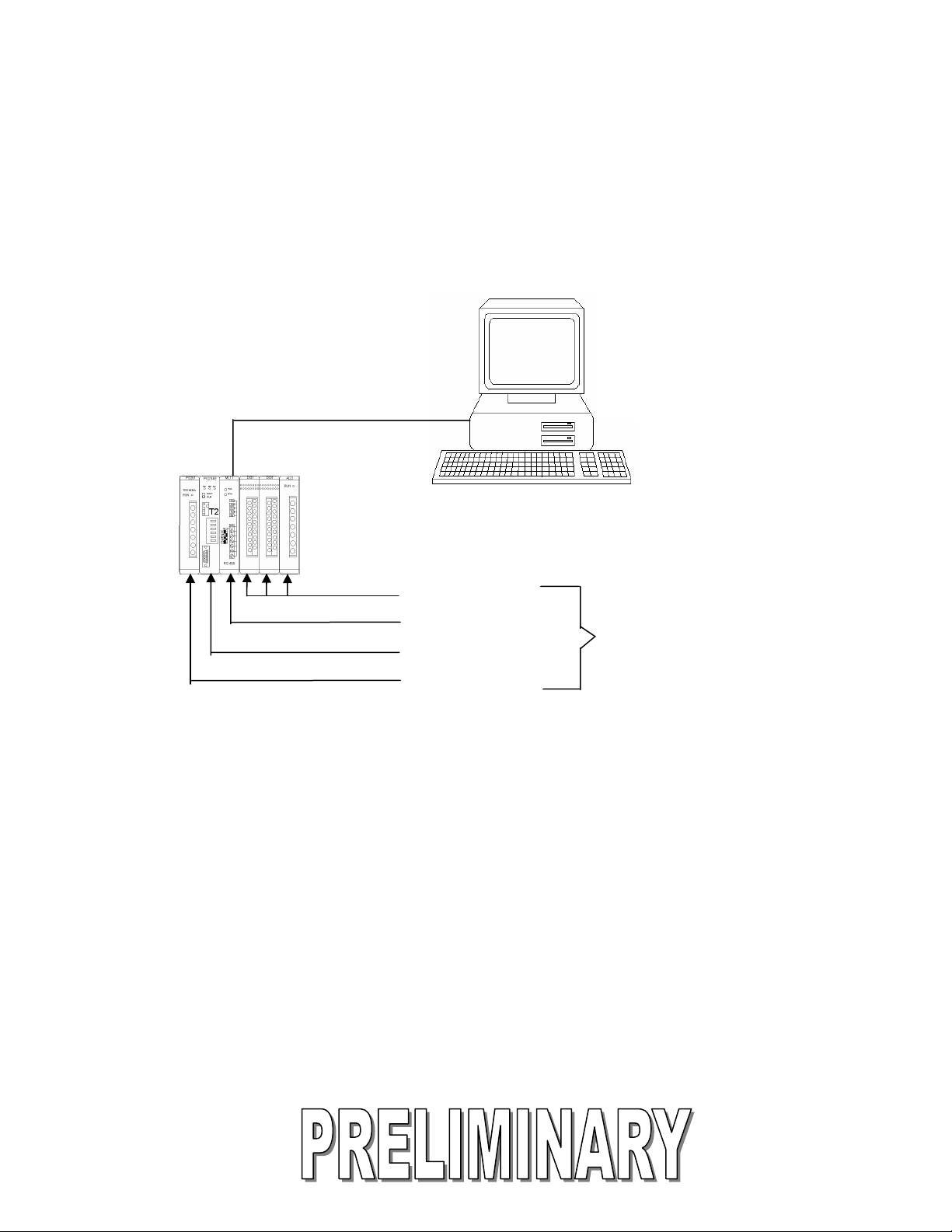
2. System Configuration
From 1 to 32 T2E or T2N PLCs can be connected to a Modbus master using the Modbus
module.
1 to 1 Configuration
Modbus Master
1. Higher Level PLC
2. Distributed Control System
3. Computer with SCADA or
RS485
T2E PLC
HMI Program
I/O Modules
Modbus Module
T2E CPU
Power Suppl
T2 Minimum
Configuration
Page 2
Page 9

1 to N Configuration
RS485
Modbus Master
1. Higher Level PLC
2. Distributed Control System
3. Computer with SCADA or
HMI Program
T2 Maximum Configuration
1 Main Unit
3 Exp. Units
Up to 32 Stations
For high-speed data transfer, one of
Toshiba’s Tosline Data Highway
modules is recommended.
Page 3
Page 10

3. External Features and Switch Settings
Page 4
Page 11

4. Specifications
ITEM SPECIFICATION
INTERFACE TERMINAL BLOCK
COMMUNICATION STYLE HALF-DUPLEX
SIGNAL CONFIGURATION TXA/RXA TXB/RXB
SYNCHRONIZATION START-STOP
NETWORK TOPOLOGY PARTY LINE (MULTIDROP)
COMMUNICATION SPEED 300, 600, 1200, 2400, 4800, 9600, 19200 bps
TRANSMISSION DISTANCE 1 KM MAX
COMMUNICATION MODE RTU MODE
DATA LENGTH 8 BITS
STOP BITS 1 BIT
PARITY EVEN, ODD, NONE
STATION NUMBER 1 TO 31 (DO NOT SELECT 0 OR 32)
ERROR CHECK PARITY CRC
NUMBER OF CHANNELS 1 CHANNEL
Page 5
Page 12

5. Modbus Module Operation
5.1. Modbus Commands
When a MODBUS command is used, the Modbus module translates it to the
corresponding T2 register access protocol.
MODBUS FUNCTION CODE
01 Read Coil Status
02 Read Input Status
03 Read Holding Register
04 Read Input Register
05 Force Single Coil
06 Force Single Register
08 Loop Back Diagnostic test
15 Force Multiple Coils
16 Preset Multiple Registers
For more information on the Modbus protocol, please refer to the Modbus Protocol Reference
Guide, see Additional References.
For more information on the T2 register access protocol, please refer to the Computer Link
Function Operation Manual, see Additional References.
T2 COMMAND
DR Read Device/Register
DR Read Device/Register
DR Read Device/Register
DR Read Device/register
DW Write Device Register
DW Write Device/Register
**** Not Supported by EX10-MML11
DW Write Device/register
DW Write Device/register
Page 6
Page 13

5.2. Modbus Data Types and T2 Register Mapping
This table shows how the different Modbus data types are mapped into T2 registers. In other
words, a Modbus master would reference the following Modbus register ranges to access the
corresponding T2 PLC registers.
For example, Modbus Holding Register 4352 will map to T2 register D000, and Input Register
0000 will map to XW00.
Data Type
Coils
Input
Status
Input
Register
Holding
Registers
Attribute Modbus No. Offset Reg/Device Address (T2)
Read/Write 0**** 0000 to 0511
0512 to 4095
4096 to 5112
7936 to 8447
Read only 1**** 0000 to 0511
0512 to 4095
Y
R
Z
Y000 to Y31F
Y320 to Y63F
R000 to R63F
Z000 to Z31F
X X000 to X31F
X320 to X63F
Read only 3**** 0000 to 0063 XW XW00 to XW63
Read/Write 4**** 0000 to 0063
0768 to 0831
1280 to 1311
3328 to 3455
3840 to 3967
4352 to 5887
YW
RW
ZW
T
C
D
YW00 to YW63
RW00 to RW63
ZW00 to ZW31
T000 to T127
C000 to C095
D000 to D1405
Page 7
Page 14

Modbus – T2 Address mapping Example:
Input module
(XW000)
Output Module
(YW001)
In this example, the T2 is being used
As a Modbus Remote Terminal Unit
slave. A Modbus master can access
The I/O or data registers in the T2.
See the following table for a Modbus to
T2 address mapping example.
T2E CPU Modbus Module
Modbus Address T2 Address T2 Data Type
30000 XW000 Input Register
40001 YW001 Output Register
44352 D0000 Data Register
Note: When dealing with I/O registers, make sure that the Modbus master is attempting to
access only the I/O points that physically exist in the T2 system. For example, Holding
Register 0 (40000) does not exist in the above example because there is no YW000 in the T2
system. In the above system, only have Holding Register 1 (40001) exists.
5.3. Restricted Registers
Registers D1406 to D1535 are reserved for “raw” data transmission with the EC300 loop
controllers on the ECBUS network. These registers are not available when the EX10-MML11
is used as a Modbus slave module. Do not use these registers.
Page 8
Page 15

6. Modbus Module Setup
The Toshiba Modbus module has been used reliably as a Modbus slave for several years.
First it was used on Toshiba’s EX100 Series PLCs and now on the T2 Series PLCs. Before it
can function as intended however, all the DIP switches must be properly set and all wiring
connections must be correct.
6.1. Modbus Module DIP Switch Settings
The following items are setup by DIP switches on the Modbus module:
• Station number
• Transmission rate (Baud rate)
• Parity
Station Number:
The station numbers identify the controllers and must be different from each other in
the network. If the EX10-MML11 address is less than 15, then set the third switch
(HAD) to the "off" position. If the EX10-MML11 address is higher than 16, set the
switch to the "on" position. Using the "STATION" dial switch (numbered in
hexadecimal) carefully set the station number. Do not set the dial switch to 0 with the
HAD switch off.
Page 9
Page 16

Transmission Rate (Baud Rate):
Select the combination of the three switches "BR2", "BR1", and "BRO" for the desired
communication speed. These are the 4th, 5th, and the 6th switches.
Baud Rate
BR2
19200
9600
ON
ON
4800
ON
2400
ON
1200
OFF
600
OFF
300
OFF
RESERVED
OFF
BR1
ON
ON
OFF
OFF
ON
ON
OFF
OFF
BR0
ON
OFF
ON
OFF
ON
OFF
ON
OFF
Page 10
Page 17

Parity Check:
Select the parity check as odd, even or none. Use switches 7 and 8 to set the parity.
PARITY
NONE
ODD
EVEN
ASY and DLY switches:
The ASY and DLY switches are not used on the EX10-MML11, and should be set to
the “Off” position.
PEN (7)
EVN (8)
OFF
----
ON
OFF
ON
ON
Page 11
Page 18

Example Configuration Settings:
This section shows how to set the card up for network station address 2, 9600 baud,
and no parity.
1) “ASY and DLY”
Set these to the Off position.
2) "Station Address"
•Set the Station number on the rotary switch to 2.
• Set the HAD switch to OFF because our address is less than 16.
3) "Communication speed"
For 9600 baud, the following settings are required.
• BR2 is on
• BR1 is on
• BR0 is off
Page 12
Page 19

4) "Parity check"
For No Parity, the following settings are required.
• PEN is off.
• EVN is off.
OFF ON
ASY
DLY
HAD
BR2
BR1
BR0
PEN
EVN
Switch settings for 9600 baud, no parity, and address less than 16.
Page 13
Page 20

6.2. Wiring Connection to the Modbus Module
Sometimes it is necessary to convert from the standard RS485 to RS232 for connection to a
Personal Computer. The wiring between the Modbus module and the converter must be set
as follows:
RS485 Converter Modbus Module
TXA RXA
RXA TXA
TXB RXB
RXB TXB
SG SG
Note: Different RS485 converters have different connections. For example, when one
commonly available converter is used, TXA connects to RXB, TXB connects to RXA, etc.
Please refer to the converter manufacturer’s instructions.
Page 14
Page 21

7. CPU Setup for the Modbus Module
Two lines of ladder logic are necessary to configure a T2 CPU for use with the Modbus
module.
1 Communications Priority: To insure uninterrupted communications between the CPU
and the Modbus module, the communications priority bit S0158 must be set ON.
2. Initialization: To initialize the Modbus module, write the initialization parameter into
data register D1470. Register D1470 must be set to H5555 (21845 Decimal) before the
Modbus module will start communicating.
When using the Modbus module, the above logic should be placed in Block 1, Rung 1 and
Rung 2 of the PLC program.
Page 15
Page 22

8. Trouble Shooting
The communication status LEDs can be used to verify correct operation of the Modbus
module. During normal operation, the LED indicators flash as follows:
• RXD LED: Flashes when the Modbus master sends a message to the EX10
-MML11. On a multi slave network, this can also flash when when the
master polls other slaves, or when other slaves respond to the master. In
general, it indicates activity on the network.
• TXD LED: Flashes when that specific EX10-MML11 responds to the master.
This LED is only relevant to the module on which it is being viewed,
regardless of how many slaves are on the network. It indicates that the
module has received a message that is uniquely addressed to it, and the
EX10-MML11 is responding. This LED is usually on longer than the RXD
LED because the responses have more data than the requests.
If the LED indicators are not flashing, check the following:
1) Wiring connections
2) Resistance at terminals
3) Baud rate setting
4) Station Number
5) HAD Switch
6) Parity selection
7) Modbus master is using standard Modbus RTU format
If the LED indicators are on solid:
The polarity has been reversed on the network wiring. For example, the “A” terminals
are wired to the “B” lines, the “+” terminals are wired to the “-“ lines, etc. Correct the
connections to the EX10-MML11.
Page 16
Page 23

9. Additional References
Toshiba Corporation, Instruction Manual - EC300 Series Controller – ECBUS Transmission
Interface Module – ML11. 6F8A0613 4th ed. Feb 1995. Tokyo, Japan.
Toshiba Corporation, Computer Link Function Operation Manual. UM-TS03-E008, 3rd ed.
Aug. 1977. Tokyo, Japan.
Gould Modicon, Modbus Protocol Reference Guide. PI-MBUS-300 Rev B. Jan 1985.
Andover, MA.
Page 17
Page 24

TOSHIBA
TOSHIBA INTERNATIONAL (EUROPE) LTD.
1 Roundwood Avenue
Stockley Park, Uxbridge
Middlesex UB11 1AR, UNITED KINGDOM
Tel: 081 848 4466 Fax: 081 848 4969
E_mail nigels@toshibai.co.uk
TOSHIBA INTERNATIONAL CORPORATION
Industrial Equipment Division
13131 West Little York Road
Houston, TX. 77041 U.S.A.
Tel: 713-466-0277 Fax: 713-466-8773
E_mail: plc@tic.toshiba.com
TOSHIBA do BRASIL, S.A.
Estrade dos Alvarengas 5500
Sao Bernardo do Campo
Sao Paulo 0985-5500, Brazil
Tel: 55-11-7689-7199
Fax: 55-11-7689-7189
antoneli@tbb.toshiba.com.br
TOSHIBA INTERNATIONAL
CORPORATION PTY. LTD.
Unit 1, 9 Orion Road Lane Cove
N.S.W. 2066, AUSTRALIA
Tel: 02-428-2077 Telex: AA25192
E_mail: preston@toshiba.co.au
TOSHIBA CORPORATION
Industrial Equipment Department
1-1, Shibaura 1-chome, Minato-ku
Tokyo 105, JAPAN
Tel: 03-3457-4900 Cable: Toshiba Tokyo
E_mail: osamu.seki@toshiba.co.jp
Toshiba Asia Pacific PTE. LTD
200 Cantonment Rd. #12-01
Southpoint, 089763 Singpore
Ph: 65-324-1048
Fax: 65-324-5286
Page 2
 Loading...