

Page 1

TOSHIBA
Satellite L350/
Satellite Pro L350/
Satellite L350D/
Satellite Pro L350D series
User’s Manual
Page 2

Copyright
Disclaimer
© 2008 by TOSHIBA Corporation. All rights reserved. Under the copyright
laws, this manual cannot be reproduced in any form without the prior written permission of TOSHIBA. No patent liability is assumed, with respect to
the use of the information contained herein.
TOSHIBA Satellite L350/Satellite Pro L350/Satellite L350D/Satellite Pro
L350D series Portable Personal Computer User’s Manual
First edition April 2008
Copyright authority for music, movies, computer programs, data bases and
other intellectual property covered by copyright laws belongs to the author
or to the copyright owner. Copyrighted material can be reproduced only for
personal use or use within the home. Any other use beyond that stipulated
above (including conversion to digital format, alteration, transfer of copied
material and distribution on a network) without the permission of the copyright owner is a violation of copyright or author’s rights and is subject to civil
damages or criminal action. Please comply with copyright laws in making
any reproduction from this manual.
This manual has been validated and reviewed for accuracy. The
instructions and descriptions it contains are accurate for the TOSHIBA
Satellite L350/Satellite Pro L350/Satellite L350D/Satellite Pro L350D series
Portable Personal Computer at the time of this manual’s production.
However, succeeding computers and manuals are subject to change
without notice. TOSHIBA assumes no liability for damages incurred directly
or indirectly from errors, omissions or discrepancies between the computer
and the manual.
T rademarks
IBM is a registered trademark, and IBM PC and PS/2 are trademarks of
International Business Machines Corporation.
Intel, Intel SpeedStep and Intel Core and Centrino are trademarks or registered trademarks of Intel Corporation or its subsidiaries in the United States
and other countries/regions.
AMD, the AMD Arrow logo, AMD Athlon, AMD Turion, Radeon, and combinations thereof, ATI Mobility Radeon are trademarks of Advanced Micro
Devices, Inc.
Windows and Microsoft are registered trademarks and Windows Vista is a
trademark of Microsoft Corporation.
Photo CD is a trademark of Eastman Kodak.
Memory Stick is a registered trademark of SonyCorporation.
DVD Movie Factory is a trademark of Ulead Systems Inc.
Labelflash™ is a trademark of YAMAHA CORPORATION.
User’s Manual i
Page 3

Manufactured under license from Digital Theater Systems, Inc. U.S. Pat.
No's. 5,451,942; 5,956,674; 5,974,380; 5,978,762; 6,226,616; 6,487,535
and other U.S. and world-wide patents issued and pending. "DTS" and
"DTS Digital Surround" are registered trademarks of Digital Theater Systems, Inc. Copyright 1996, 2003 Digital Theater Systems, Inc. All Rights
Reserved.
Other trademarks and registered trademarks not listed above may be used
in this manual.
Macrovision License of Notice
For RTLA(Restricted Technology License Agreement)
This product incorporates copyright protection technology that is protected
by U.S. patents and foreign patents, including patent numbers 5,315,448
and 6,836,549, and other intellectual property rights. The use of
Macrovision's copy protection technology in the product must be authorized
by Macrovision. Reverse engineering or disassembly is prohibited. The
copyright protection technology availability depends on the model you
purchased.
Safety instructions
Use the following safety guidelines to help to protect yourself and your
computer.
When using your computer
Do not operate your portable computer for an extended period of time with
the base resting directly on your body. With extended operation, heat can
potentially build up in the base. Allowing sustained contact with the skin
could cause discomfort or, eventually, a burn
■ Do not attempt to service the computer yourself. Always follow
installation instructions closely.
■ Do not carry a battery in your pocket, purse, or other container where
metal objects (such as car keys) could short-circuit the battery
terminals. The resulting excessive current follow can cause extremely
high temperatures and may result in damage from burns.
■ Be sure that nothing rests on your AC adaptor’s power cable and that
the cable is not located where it can be tripped over or stepped on.
■ Place the AC adaptor in a ventilated area, such as a desk top or on the
floor, when you use it to run the computer or to charge the battery. Do
not cover the AC adaptor with papers or other items that will reduce
cooling; also, do not use the AC adaptor while it is inside a carrying
case.
User’s Manual ii
.
Page 4

■ Use only the AC adaptor and batteries that are approved for use with
this computer. Use of another type of battery or AC adaptor may risk fire
or explosion.
■ Before you connect the computer to a power source, ensure that the
voltage rating of the AC adaptor matches that of the available power
source. 115 V/60 Hz in most of North and South America and some Far
Eastern countries such as Taiwan. 100 V/50 Hz in eastern Japan and
100 V/60 Hz in western Japan. 230 V/50 Hz in most of Europe, the
Middle East, and the Far East.
■ If you use an extension cable with your AC adaptor, ensure that the total
ampere rating of the products plugged in to the extension cable does
not exceed the ampere rating of the extension cable.
■ To remove power from the computer, turn it off, remove the battery, and
disconnect the AC adaptor from the electrical outlet.
■ To help avoid the potential hazard of electric shock, do not connect or
disconnect any cables or perform maintenance or reconfiguration of this
product during an electrical storm.
■ When setting up the computer for work, place it on a level surface.
FCC information
FCC notice “Declaration of Conformity Information”
This equipment has been tested and found to comply with the limits for a
Class B digital device, pursuant to part 15 of the FCC rules. These limits
are designed to provide reasonable protection against harmful interference
in a residential installation. This equipment generates, uses and can radiate
radio frequency energy and, if not installed and used in accordance with the
instructions, may cause harmful interference to radio communications.
However, there is no guarantee that interference will not occur in a
particular installation. If this equipment does cause harmful interference to
radio or television reception, which can be determined by turning the
equipment off and on, the user is encouraged to try to correct the
interference by one or more of the following measures:
■ Reorient or relocate the receiving antenna.
■ Increase the separation between the equipment and receiver.
■ Connect the equipment into an outlet on a circuit different from that to
which the receiver is connected.
■ Consult the dealer or an experienced radio/TV technician for help.
User’s Manual iii
Page 5
Only peripherals complying with the FCC class B limits may be attached to
this equipment. Operation with non-compliant peripherals or peripherals
not recommended by TOSHIBA is likely to result in interference to radio
and TV reception. Shielded cables must be used between the external
devices and the computer’s external monitor port, USB port, and
microphone jack. Changes or modifications made to this equipment, not
expressly approved by TOSHIBA or parties authorized by TOSHIBA could
void the user’s authority to operate the equipment.
FCC conditions
This device complies with part 15 of the FCC Rules. Operation is subject to
the following two conditions:
1. This device may not cause harmful interference.
2. This device must accept any interference received, including
interference that may cause undesired operation.
Contact
Address: TOSHIBA America Information Systems, Inc.
9740 Irvine Boulevard
Irvine, California 92618-1697
Telephone: (949) 583-3000
EU Declaration of Comformity
Supplementary Information: The product complies with the requirements
Of the Low Voltage Directive 2006/95/EC,the EMC Directive 2004/108/EC
and/or the R&TTE Directive 1999/5/EC.”
This product is carrying the CE-Mark in accordance with the related
European Directives. Responsible for CE-Marking is TOSHIBA Europe,
Hammfelddamm 8, 41460 Neuss, Germany.
VCCI Class B Information
User’s Manual iv
Page 6

Canadian regulatory information (Canada only)
This digital apparatus does not exceed the Class B limits for radio noise
emissions from digital apparatus as set out in the Radio Interference
Regulation of the Canadian Department of Communications.
Note that Canadian Department of Communications (DOC) regulations
provide, that changes or modifications not expressly approved by
TOSHIBA Corporation could void your authority to operate this equipment.
This Class B digital apparatus meets all requirements of the Canadian
Interference-Causng Equipment Regulations.
Cet appareil numérique de la class B respecte toutes les exgences du
Règlement sur le matériel brouileur du Canada.
Modem warning notice
Conformity statement
The equipment has been approved to [Commission Decision “CTR21”] for
pan-European single terminal connection to the Public Switched T elephone
Network (PSTN).
However, due to differences between the individual PSTNs provided in
different countries/regions the approval does not, of itself, give an
unconditional assurance of successful operation on every PSTN network
termination point.
In the event of problems, you should contact your equipment supplier in the
first instance.
Network compatibility statement
This product is designed to work with, and is compatible with the following
networks. It has been tested to and found to conform with the additional
requirements conditional in EG 201 121.
Germany ATAAB AN005,AN006,AN007,AN009,AN010
and DE03,04,05,08,09,12,14,17
Greece ATAAB AN005,AN006 and GR01,02,03,04
Portugal ATAAB AN001,005,006,007,011 and
P03,04,08,10
Spain ATAAB AN005,007,012, and ES01
Switzerland ATAAB AN002
All other countries/regions ATAAB AN003,004
Specific switch settings or software setup is required for each network,
please refer to the relevant sections of the user guide for more details.
The hookflash (timed break register recall) function is subject to separate
national type approvals. It has not been tested for conformity to national
type regulations, and no guarantee of successful operation of that specific
function on specific national networks can be given.
User’s Manual v
Page 7

Japan regulations
Region selection
If you are using the computer in Japan, technical regulations described in
the Telecommunications Business Law require that you select the Japan
region mode. It is illegal to use the modem in Japan with any other
selection.
Redial
Up to two redial attempts can be made. If more than two redial attempts are
made, the modem will return
problems with the Black Listed code, set the interval between redials at one
minute or longer.
Japan’s Telecommunications Business Law permits up to two redials on
analogue telephones, but the redials must be made within a total of three
minutes.
The internal modem is approved by Japan Approvals Institute for
Telecommunications Equipment.
A05-0413001
A05-0025001
A05-5016201
Black Listed. If you are experiencing
Pursuant to FCC CFR 47, Part 68:
When you are ready to install or use the modem, call your local telephone
company and give them the following information:
■ The telephone number of the line to which you will connect the modem
■ The registration number that is located on the device.
US: AGSMD01BDELPHI
S56MD01B13054
CXSMM01BRD02D330
The FCC registration number of the modem will be found on either the
device which is to be installed, or, if already installed, on the bottom of
the computer outside of the main system label.
■ The Ringer Equivalence Number (REN) of the modem, which can vary.
For the REN of your modem, refer to your modem’s label.
The modem connects to the telephone line by means of a standard jack
called the USOC RJ11C.
User’s Manual vi
Page 8

Type of service
Your modem is designed to be used on standard-device telephone lines.
Connection to telephone company-provided coin service (central office
implemented systems) is prohibited. Connection to party lines service is
subject to state tariffs. If you have any questions about your telephone line,
such as how many pieces of equipment you can connect to it, the
telephone company will provide this information upon request.
Telephone company procedures
The goal of the telephone company is to provide you with the best service it
can. In order to do this, it may occasionally be necessary for them to make
changes in their equipment, operations, or procedures. If these changes
might affect your service or the operation of your equipment, the telephone
company will give you notice in writing to allow you to make any changes
necessary to maintain uninterrupted service.
If problems arise
If any of your telephone equipment is not operating properly, you should
immediately remove it from your telephone line, as it may cause harm to
the telephone network. If the telephone company notes a problem, they
may temporarily discontinue service. When practical, they will notify you in
advance of this disconnection. If advance notice is not feasible, you will be
notified as soon as possible. When you are notified, you will be given the
opportunity to correct the problem and informed of your right to file a
complaint with the FCC. In the event repairs are ever needed on your
modem, they should be performed by TOSHIBA Corporation or an
authorized representative of TOSHIBA Corporation.
Disconnection
If you should ever decide to permanently disconnect your modem from its
present line, please call the telephone company and let them know of this
change.
Fax branding
The Telephone Consumer Protection Act of 1991 makes it unlawful for any
person to use a computer or other electronic device to send any message
via a telephone fax machine unless such message clearly contains in a
margin at the top or bottom of each transmitted page or on the first page of
the transmission, the date and time it is sent and an identification of the
business, other entity or individual sending the message and the telephone
number of the sending machine or such business, other entity or individual.
In order to program this information into your fax modem, you should
complete the setup of your fax software before sending messages.
Use only NO. 26 AWG or larger telecommunication line cord.
User’s Manual vii
Page 9

Instructions for IC CS-03 certified equipment
1 The Industry Canada label identifies certified equipment. This certifica-
tion means that the equipment meets certain telecommunications network protective, operational and safety requirements as prescribed in
the appropriate Terminal Equipment Technical Requirements document(s). The Department does not guarantee the equipment will operate to the user’s satisfaction.
Before installing this equipment, users should ensure that it is permissible to be connected to the facilities of the local telecommunications
company. The equipment must also be installed using an acceptable
method of connection.
The customer should be aware that compliance with the above conditions may not prevent degradation of service in some situations.
Repairs to certified equipment should be coordinated by a representative designated by the supplier. Any repairs or alterations made by the
user to this equipment, or equipment malfunctions, may give the telecommunications company cause to request the user to disconnect the
equipment.
Users should ensure for their own protection that the electrical ground
connections of the power utility, telephone lines and internal metallic
water pipe system, if present, are connected together. This precaution
may be particularly important in rural areas.
Users should not attempt to make such connections themselves, but
should contact the appropriate electric inspection authority, or electrician,
as appropriate.
2 The user manual of analog equipment must contain the equipment’s
Ringer Equivalence Number (REN) and an explanation notice similar
to the following:
The Ringer Equivalence Number (REN) of the modem, which can vary . For
the REN of your modem, refer to your modem’s label
.
The Ringer Equivalence Number (REN) assigned to each terminal device
provides an indication of the maximum number of terminals allowed to be
connected to a telephone interface. The termination on an interface may
consist of any combination of devices subject only to the requirement that
the sum of the Ringer Equivalence Numbers of all the devices does not
exceed 5.
3 The standard connecting arrangement (telephone jack type) for this
equipment is jack type(s): USOC RJ11C.
The IC registration number of the modem is shown below.
Canada: 4005B-DELPHI
109AH-ML3054
3652B-RD02D330
User’s Manual viii
Page 10

Notes for users in Australia and New Zealand
Modem warning notice for Australia
Modems connected to the Australian telecoms network must have a valid
Austel permit. This modem has been designed to specifically configure to
ensure compliance with Austel standards when the country/region selection
is set to Australia. The use of other country/region setting while the modem
is attached to the Australian PSTN would result in you modem being operated in a non-compliant manner. To verify that the country/region is correctly set, enter the command ATI which displays the currently active
setting.
To set the country/region permanently to Australia, enter the following command sequence:
AT%TE=1
ATS133=1
AT&F
AT&W
AT%TE=0
ATZ
Failure to set the modem to the Australia country/region setting as shown
above will result in the modem being operated in a non-compliant manner.
Consequently, there would be no permit in force for this equipment and the
Telecoms Act 1991 prescribes a penalty of $12,000 for the connection of
non-permitted equipment.
Notes for use of this device in New Zealand
■ The grant of a Telepermit for a device in no way indicates Telecom
acceptance of responsibility for the correct operation of that device
under all operating conditions. In particular the higher speeds at which
this modem is capable of operating depend on a specific network
implementation which is only one of many ways of delivering high
quality voice telephony to customers. Failure to operate should not be
reported as a fault to Telecom.
■ In addition to satisfactory line conditions a modem can only work
properly if:
(a) it is compatible with the modem at the other end of the call and
(b) the application using the modem is compatible with the applica-
tion at the other end of the call - e.g., accessing the Internet
requires suitable software in addition to a modem.
■ This equipment shall not be used in any manner which could constitute
a nuisance to other Telecom customers.
User’s Manual ix
Page 11

■ Some parameters required for compliance with Telecom’s PTC
Specifications are dependent on the equipment (PC) associated with
this modem. The associated equipment shall be set to operate within
the following limits for compliance with Telecom Specifications:
(a) There shall be no more than 10 call attempts to the same number
within any 30 minute period for any single manual call initiation,
and
(b) The equipment shall go on-hook for a period of not less than 30
seconds between the end of one attempt and the beginning of the
next.
(c) Automatic calls to different numbers shall be not less than 5 sec-
onds apart.
■ Immediately disconnect this equipment should it become physically
damaged, and arrange for its disposal or repair.
■ The correct settings for use with this modem in New Zealand are as
follows:
ATB0 (CCITT operation)
AT&G2 (1800 Hz guard tone)
AT&P1 (Decadic dialing make-break ratio = 33%/67%)
ATS0=0 (not auto answer)
A TS10=less than 150 (loss of carrier to hangup delay , factory default of
15 recommended)
ATS11=90 (DTMF dialing on/off duration=90 ms)
ATX2 (Dial tone detect, but not (U.S.A.) call progress detect)
■ When used in the Auto Answer mode, the S0 register must be set with a
value of 3 or 4. This ensures:
(a) a person calling your modem will hear a short burst of ringing
before the modem answers. This confirms that the call has been
successfully switched through the network.
(b) caller identification information (which occurs between the first
and second ring cadences) is not destroyed.
■ The preferred method of dialing is to use DTMF tones (ATDT...) as this
is faster and more reliable than pulse (decadic) dialing. If for some
reason you must use decadic dialing, your communications program
must be set up to record numbers using the following translation table
as this modem does not implement the New Zealand “Reverse Dialing”
standard.
Number to be dialed: 0 1 2 3 4 5 6 7 8 9
Number to program into computer: 0 9 8 7 6 5 4 3 2 1
Note that where DTMF dialing is used, the numbers should be entered
normally.
User’s Manual x
Page 12

■ The transmit level from this device is set at a fixed level and because of
this there may be circumstances where the performance is less than
optimal. Before reporting such occurrences as faults, please check the
line with a standard Telepermitted telephone, and only report a fault if
the phone performance is impaired.
■ It is recommended that this equipment be disconnected from the
Telecom line during electrical storms.
■ When relocating the equipment, always disconnect the Telecom line
connection before the power connection, and reconnect the power first.
■ This equipment may not be compatible with Telecom Distinctive Alert
cadences and services such as FaxAbility.
NOTE THAT FAULT CALLOUTS CAUSED BY ANY OF THE ABOVE
CAUSES MAY INCUR A CHARGE FROM TELECOM
General conditions
As required by PTC 100, please ensure that this office is advised of any
changes to the specifications of these products which might affect compliance with the relevant PTC Specifications.
The grant of this Telepermit is specific to the above products with the marketing description as stated on the T elepermit label artwork. The Telepermit
may not be assigned to other parties or other products without Telecom
approval.
A Telepermit artwork for each device is included from which you may prepare any number of Telepermit labels subject to the general instructions on
format, size and colour on the attached sheet.
The Telepermit label must be displayed on the product at all times as proof
to purchasers and service personnel that the product is able to be legitimately connected to the Telecom network.
The Telepermit label may also be shown on the packaging of the product
and in the sales literature, as required in PTC 100.
The charge for a Telepermit assessment is $337.50. An additional charge
of $337.50 is payable where an assessment is based on reports against
non-Telecom New Zealand Specifications. $112.50 is charged for each variation when submitted at the same time as the original.
An invoice for $NZ1237.50 will be sent under separate cover.
User’s Manual xi
Page 13

Following information is only for EU-member States
The symbol indicates that this product may not be treated as household
waste. Please ensure this product is properly disposed as inappropriate
waste handling of this product may cause potential hazards to the environment and human health.
For more detailed information about recycling of this product, please
contact your local city office, your household waste disposal service or the
shop where you purchased the product.
This symbol may not be displayed depending on the country and region
where you purchased.
ENERGY STAR
®
Program
Y our computer model may be ENERGY ST AR
purchased is compliant, it is labeled with the ENERGY STAR
®
Compliant. If the model you
®
logo on the
computer and the following information applies.
TOSHIBA is a partner in the Environmental Protection Agency's (EPA)
ENERGY STAR
latest ENERGY STAR
®
Program and has designed this computer to meet the
®
guidelines for energy efficiency. Your computer
ships with the power management options preset to a configuration that will
provide the most stable operating environment and optimum system
performance for both AC power and battery modes.
To conserve energy, your computer is set to enter the low-power Sleep
mode which shuts down the system and display within 15 minutes of
inactivity in AC power mode. We recommend that you leave this and other
energy saving features active, so that your computer will operate at its
maximum energy efficiency. You can wake the computer from Sleep mode
by pressing the power button.
According to the EPA, a computer meeting the new ENERGY STAR
®
specifications will use between 20% and 50% less energy depending on
how it is used. If all U.S. household and businesses replaced old computers
with new ENERGY ST AR
®
qualified models, we would save more than $1.8
billion in energy costs over the next five years and avoid greenhouse gas
emissions equivalent to more than 2.7 million cars.
If every computer purchased by businesses next year met the new
ENERGY STAR
®
requirements, businesses would save more than $210
million over the lifetime of those models. That is equivalent to lighting 120
million square feet of U.S. commercial building space each year.
Visit http://www.energystar.gov
or
http://www.energystar.gov/powermanagement
for more information regarding the ENERGY STAR® Program.
User’s Manual xii
Page 14

Optical disc drive standards
TOSHIBA Satellite L350/Satellite Pro L350/Satellite L350D/Satellite Pro
L350D series computer is shipped with one of the following drives
preinstalled:CD-RW/DVD-ROM, DVD Super Multi (+-R DL), or DVD Super
Multi (+-R DL) /w Label Flash drive.
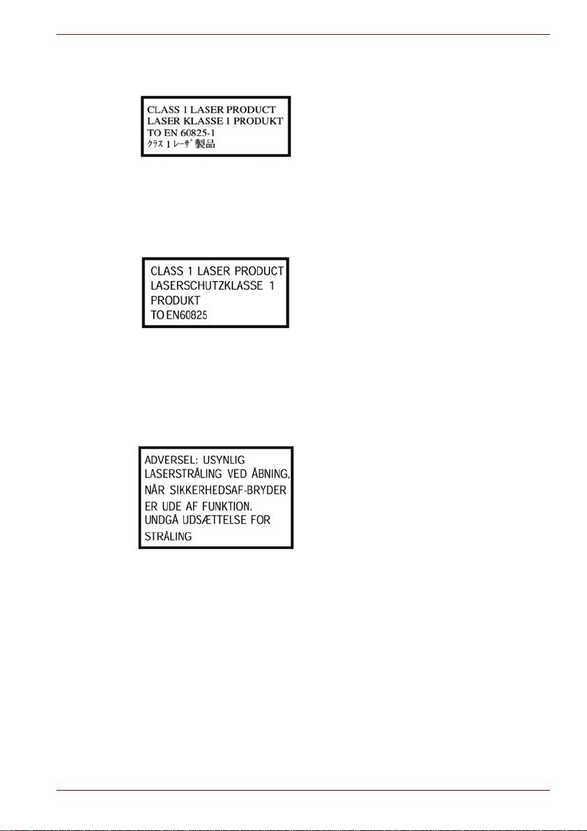
The drive has one of the following labels:
CLASS 1 LASER PRODUCT
LASER KLASSE 1
LUOKAN 1 LASERLAITE
APPAREIL A LASER DE CLASSE1
KLASS 1 LASER APPARAT
Before it is shipped, the Class 1 Laser is certified to meet the United States
Chapter 21 Standards of the Department of Health and Human Services
(DHHS 21 CFR).
For any other country, the drive is certified to meet the Class 1 Laser
standards of IEC825 and EN60825.
Optical disc drive safety instructions
■ The drive employs a laser system. To ensure proper use of this
product, please read this instruction manual carefully and retain for
future reference.
Should the unit ever require maintenance, contact an authorized
service location.
■ Use of controls, adjustments or the performance of procedures other
than those specified may result in hazardous radiation exposure
■ To prevent direct exposure to the laser beam, do not try to open the
enclosure.
User’s Manual xiii
Page 15
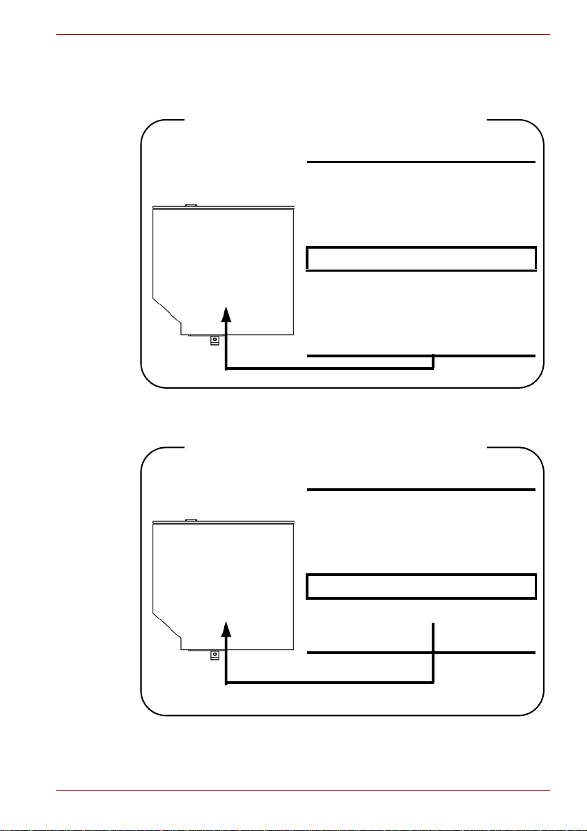
CD-RW/DVD-ROM drive
Toshiba Samsung TS-L462D/TS-L463A
Location of the required label
PRODUCT IS CERTIFIED BY THE
MANUFACTURER TO COMPLY WITH
DHHS RULES 21 CFR SUBCHAPTER
J APPLICABLE AT THE DATE OF
MANUFACTURE.
MANUFACTURED
Toshiba Samsung Strage Technology
Korea corporation
416, Maetan-3Dong, Yeongtong-Gu
Suwon City, Gyeonggi-Do, 443-742,
Korea
TEAC DW-224E/DW-224S
Location of the required label
PRODUCT IS CERTIFIED BY THE
MANUFACTURER TO COMPLY WITH
DHHS RULES 21 CFR SUBCHAPTER
J APPLICABLE AT THE DATE OF
MANUFACTURE.
MANUFACTURED
TEAC CORPORATION
1-47 OCHIAI, TAMA-SHI,
TOKYO, JAPAN
User’s Manual xiv
Page 16
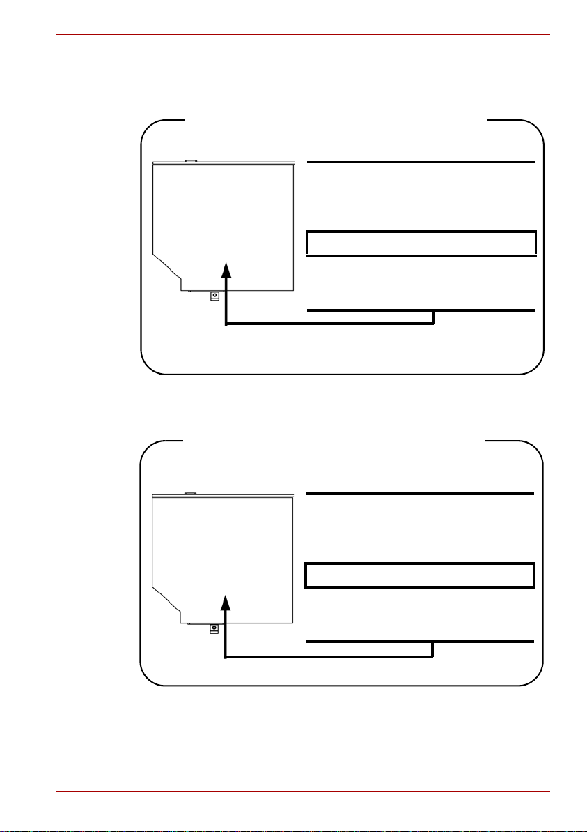
DVD Super Multi (+-R DL) drive
Panasonic UJ-870B/UJ-870F/UJ-870AB/UJ-870EB
Location of the required label
COMPLIES WITH FDA RADIATION
PERFORMANCE STANDARDS, 21
CFR SUBCHAPTER J.
MANUFACTURED
Panasonic Communications Co., Ltd.
1-62, 4-Chome Minoshima
Hakata-ku Fukuoka, Japan
HLDS GSA-T40N/GSA-T40F/GSA-T50N/GSA-T50F
Location of the required label
COMPLIES WITH FDA RADIATION
PERFORMANCE STANDARDS, 21
CFR SUBCHAPTER J.
MANUFACTURED
Hitachi-LG Data Storage, Inc.
22-23, Kaigan 3-chome, Minato-Ku,
Tokyo, 108-0022 Japan
User’s Manual xv
Page 17

Pioneer DVR-KD08TBM/DVR-KD08TBF/
DVR-TD08TBM/DVR-TD08TBF
Location of the required label
COMPLIES WITHFDA RADIATION
PERFORMANCE STANDARDS, 21
CFR SUBCHAPTER J
MANUFACTURED
PIONEER CORPORATION
4-1, MEGURO 1-CHOME, MEGUROKU TOKYO 153-8654, JAPAN
Toshiba Samsung TS-L632H/TS-L632P/TS-L633A/TS-L633P
Location of the required label
PRODUCT IS CERTIFIED BY THE
MANUFACTURER TO COMPLY WITH
DHHS RULES 21 CFR CHAPTER 1,
SUBCHAPTER J, APPLICABLE AT
THE DATE OF MANUFACTURE.
MANUFACTURED
Toshiba Samung Storage Technology
Korea Corporation
416, Maetan-3Dong, Yeongtong-Gu,
Suwon City, Gyeonggi-Do, 443-742,
Korea
User’s Manual xvi
Page 18
International precautions
CAUTION: This appliance contains a
laser system and is classified as a
“CLASS 1 LASER PRODUCT.” To use
this model properly, read the instruction
manual carefully and keep this manual
for your future reference. In case of any
trouble with this model, please contact
your nearest “AUTHORIZED service
station.” T o prevent direct exposure to the
laser beam, do not try to open the
enclosure.
VORSICHT: Dieses Gerät enthält ein
Laser-System und ist als
“LASERSCHUTZKLASSE 1 PRODUKT”
klassifiziert. Für den richtigen Gebrauch
dieses Modells lesen Sie bitte die
Bedienungsanleitung sorgfältig durch
und bewahren diese bitte als Referenz
auf. Falls Probleme mit diesem Modell
auftreten, benachrichtigen Sie bitte die
nächste “autorisierte Service-Vertretung”.
Um einen direkten Kontakt mit dem
Laserstrahl zu vermeiden darf das Gerät
nicht geöffnet werden.
User’s Manual xvii
ADVARSEL: Denne mærking er anbragt
udvendigt på apparatet og indikerer, at
apparatet arbejder med laserstråler af
klasse 1, hviket betyder, at der anvendes
laserstrlier af svageste klasse, og at man
ikke på apparatets yderside kan bilve
udsat for utilladellg kraftig stråling.
APPARATET BOR KUN ÅBNES AF
FAGFOLK MED SÆRLIGT KENDSKAB
TIL APPARATER MED
LASERSTRÅLER!
Indvendigt i apparatet er anbragt den her
gengivne advarselsmækning, som
advarer imod at foretage sådanne
indgreb i apparatet, at man kan komme til
at udsatte sig for laserstråling.
Page 19

Important notice
OBS! Apparaten innehåller
laserkomponent som avger laserstråining
överstigande gränsen för laserklass 1.
VAROITUS. Suojakoteloa si saa avata.
Laite sisältää laserdiodin, joka lähetää
näkymätöntä silmilie vaarallista
lasersäteilyä.
CAUTION: USE OF CONTROLS OR
ADJUSTMENTS OR PERFORMANCE
OF PROCEDURES OTHER THAN
THOSE SPECIFIED IN THE OWNER’S
MANUAL MAY RESULT IN
HAZARDOUS RADIATION EXPOSURE.
VORSICHT: DIE VERWENDUNG VON
ANDEREN STEUERUNGEN ODER
EINSTELLUNGEN ODER DAS
DURCHFÜHREN VON ANDEREN
VORGÄNGEN ALS IN DER
BEDIENUNGSANLEITUNG
BESCHRIEBEN KÖNNEN
GEFÄHRLICHE
STRAHLENEXPOSITIONEN ZUR
FOLGE HABEN.
Copyrighted works including, but not limited to music, video, computer program, databases are protected by copyright laws. Unless specifically permitted under applicable copyright laws, you cannot copy, modify, assign,
transmit or otherwise dispose of any copyrighted work with the consent of
the owner of the copyright. Please take notice that unauthorized copying,
modification, assignment, transmission and disposition may be subject to
claims for damages and penalties.
■ Avoid using a telephone (other than a cordless type) during an electrical
storm. There may be a remote risk of electric shock from lightning.
■ Do not use the telephone to report a gas leak in the vicinity of the leak.
■ Use only the power cord indicated in this manual.
■ Replace only with the same or equivalent type battery recommended by
the manufacturer.
■ Dispose of used batteries according to the manufacturer’s instructions.
Use only the battery pack that came with the computer or an optional
battery pack. Use of wrong battery could damage your computer.
TOSHIBA assumes no liability for any damage in such case.
User’s Manual xviii
Page 20

Table of Contents
Preface
General Precautions
Chapter 1 Introduction
Equipment checklist. . . . . . . . . . . . . . . . . . . . . . . . . . . . . . . . . . . . . . . 1-1
Hardware . . . . . . . . . . . . . . . . . . . . . . . . . . . . . . . . . . . . . . . . . . . . . 1-1
Software . . . . . . . . . . . . . . . . . . . . . . . . . . . . . . . . . . . . . . . . . . . . . . 1-2
Documentation . . . . . . . . . . . . . . . . . . . . . . . . . . . . . . . . . . . . . . . . . 1-2
Features. . . . . . . . . . . . . . . . . . . . . . . . . . . . . . . . . . . . . . . . . . . . . . . . . 1-2
Processor . . . . . . . . . . . . . . . . . . . . . . . . . . . . . . . . . . . . . . . . . . . . . 1-2
Memory. . . . . . . . . . . . . . . . . . . . . . . . . . . . . . . . . . . . . . . . . . . . . . . 1-3
Disks. . . . . . . . . . . . . . . . . . . . . . . . . . . . . . . . . . . . . . . . . . . . . . . . . 1-4
Keyboard. . . . . . . . . . . . . . . . . . . . . . . . . . . . . . . . . . . . . . . . . . . . . . 1-5
Pointing device . . . . . . . . . . . . . . . . . . . . . . . . . . . . . . . . . . . . . . . . . 1-6
Power . . . . . . . . . . . . . . . . . . . . . . . . . . . . . . . . . . . . . . . . . . . . . . . . 1-6
Ports . . . . . . . . . . . . . . . . . . . . . . . . . . . . . . . . . . . . . . . . . . . . . . . . . 1-6
Slots . . . . . . . . . . . . . . . . . . . . . . . . . . . . . . . . . . . . . . . . . . . . . . . . . 1-6
Multimedia. . . . . . . . . . . . . . . . . . . . . . . . . . . . . . . . . . . . . . . . . . . . . 1-7
Communications. . . . . . . . . . . . . . . . . . . . . . . . . . . . . . . . . . . . . . . . 1-7
Security. . . . . . . . . . . . . . . . . . . . . . . . . . . . . . . . . . . . . . . . . . . . . . . 1-7
Software . . . . . . . . . . . . . . . . . . . . . . . . . . . . . . . . . . . . . . . . . . . . . . 1-8
Special features . . . . . . . . . . . . . . . . . . . . . . . . . . . . . . . . . . . . . . . . . . 1-8
TOSHIBA Value Added Package. . . . . . . . . . . . . . . . . . . . . . . . . . . . 1-10
Utilities and applications. . . . . . . . . . . . . . . . . . . . . . . . . . . . . . . . . . 1-11
Options . . . . . . . . . . . . . . . . . . . . . . . . . . . . . . . . . . . . . . . . . . . . . . . . 1-13
Chapter 2 The Grand Tour
Front with the display closed . . . . . . . . . . . . . . . . . . . . . . . . . . . . . . . 2-1
Left side. . . . . . . . . . . . . . . . . . . . . . . . . . . . . . . . . . . . . . . . . . . . . . . . . 2-3
Right side . . . . . . . . . . . . . . . . . . . . . . . . . . . . . . . . . . . . . . . . . . . . . . . 2-4
Back side. . . . . . . . . . . . . . . . . . . . . . . . . . . . . . . . . . . . . . . . . . . . . . . . 2-5
Underside . . . . . . . . . . . . . . . . . . . . . . . . . . . . . . . . . . . . . . . . . . . . . . . 2-6
Front with the display open. . . . . . . . . . . . . . . . . . . . . . . . . . . . . . . . . 2-7
Function Button . . . . . . . . . . . . . . . . . . . . . . . . . . . . . . . . . . . . . . . . . . 2-8
System indicators. . . . . . . . . . . . . . . . . . . . . . . . . . . . . . . . . . . . . . . . . 2-9
User’s Manual xix
Page 21

Keyboard indicators. . . . . . . . . . . . . . . . . . . . . . . . . . . . . . . . . . . . . . 2-11
Optical disc drive . . . . . . . . . . . . . . . . . . . . . . . . . . . . . . . . . . . . . . . . 2-11
Region codes for DVD drives and media . . . . . . . . . . . . . . . . . . . . .2-11
Writable discs . . . . . . . . . . . . . . . . . . . . . . . . . . . . . . . . . . . . . . . . . 2-12
CD-RW/DVD-ROM drive. . . . . . . . . . . . . . . . . . . . . . . . . . . . . . . . . 2-12
DVD Super Multi (+-R DL) drive . . . . . . . . . . . . . . . . . . . . . . . . . . . 2-13
AC adaptor . . . . . . . . . . . . . . . . . . . . . . . . . . . . . . . . . . . . . . . . . . . . . 2-14
Chapter 3 Getting Started
Connecting the AC adaptor. . . . . . . . . . . . . . . . . . . . . . . . . . . . . . . . . 3-2
Opening the display. . . . . . . . . . . . . . . . . . . . . . . . . . . . . . . . . . . . . . . 3-3
Turning on the power. . . . . . . . . . . . . . . . . . . . . . . . . . . . . . . . . . . . . . 3-3
Starting up for the first time . . . . . . . . . . . . . . . . . . . . . . . . . . . . . . . . 3-4
Turning off the power. . . . . . . . . . . . . . . . . . . . . . . . . . . . . . . . . . . . . . 3-4
Shut down mode (Boot mode) . . . . . . . . . . . . . . . . . . . . . . . . . . . . . 3-4
Hibernation mode . . . . . . . . . . . . . . . . . . . . . . . . . . . . . . . . . . . . . . . 3-4
Sleep mode . . . . . . . . . . . . . . . . . . . . . . . . . . . . . . . . . . . . . . . . . . . . 3-6
Restarting the computer . . . . . . . . . . . . . . . . . . . . . . . . . . . . . . . . . . . 3-7
System recovery options. . . . . . . . . . . . . . . . . . . . . . . . . . . . . . . . . . . 3-7
System recovery options. . . . . . . . . . . . . . . . . . . . . . . . . . . . . . . . . . 3-7
Create optical recovery discs . . . . . . . . . . . . . . . . . . . . . . . . . . . . . . 3-8
Restoring the preinstalled software from the recovery HDD. . . . . . . 3-8
Restoring the preinstalled software from your creating recovery
media . . . . . . . . . . . . . . . . . . . . . . . . . . . . . . . . . . . . . . . . . . . . . . . . 3-9
Chapter 4 Operating Basics
Using the touchpad . . . . . . . . . . . . . . . . . . . . . . . . . . . . . . . . . . . . . . . 4-1
Using optical disc drives. . . . . . . . . . . . . . . . . . . . . . . . . . . . . . . . . . . 4-2
Loading discs . . . . . . . . . . . . . . . . . . . . . . . . . . . . . . . . . . . . . . . . . . 4-3
Removing discs. . . . . . . . . . . . . . . . . . . . . . . . . . . . . . . . . . . . . . . . . 4-5
Function Button. . . . . . . . . . . . . . . . . . . . . . . . . . . . . . . . . . . . . . . . . 4-6
Writing CDs on CD-RW/DVD-ROM drive. . . . . . . . . . . . . . . . . . . . . . . 4-7
Important message (CD-RW/DVD-ROM drive). . . . . . . . . . . . . . . . . 4-7
Before writing or rewriting. . . . . . . . . . . . . . . . . . . . . . . . . . . . . . . . . 4-7
When writing or rewriting . . . . . . . . . . . . . . . . . . . . . . . . . . . . . . . . . 4-8
Disclaimer (CD-RW/DVD-ROM drive) . . . . . . . . . . . . . . . . . . . . . . . 4-9
Writing CD/DVDs on DVD Super Multi (+-R DL) drive. . . . . . . . . . . . 4-9
Important message (DVD Super Multi (+-R DL) drive). . . . . . . . . . . . 4-9
Before writing or rewriting. . . . . . . . . . . . . . . . . . . . . . . . . . . . . . . . . 4-9
When writing or rewriting . . . . . . . . . . . . . . . . . . . . . . . . . . . . . . . . 4-12
Disclaimer (DVD Super Multi (+-R DL) drive) . . . . . . . . . . . . . . . . . 4-13
TOSHIBA Disc Creator. . . . . . . . . . . . . . . . . . . . . . . . . . . . . . . . . . . . 4-13
Data verification . . . . . . . . . . . . . . . . . . . . . . . . . . . . . . . . . . . . . . . 4-14
How to learn more about TOSHIBA Disc Creator. . . . . . . . . . . . . . 4-14
Video . . . . . . . . . . . . . . . . . . . . . . . . . . . . . . . . . . . . . . . . . . . . . . . . . . 4-15
User’s Manual xx
Page 22

When Using Ulead DVD Movie Factory® for TOSHIBA. . . . . . . . . 4-15
Media care. . . . . . . . . . . . . . . . . . . . . . . . . . . . . . . . . . . . . . . . . . . . . . 4-17
CD/DVD . . . . . . . . . . . . . . . . . . . . . . . . . . . . . . . . . . . . . . . . . . . . . 4-17
Using the web camera . . . . . . . . . . . . . . . . . . . . . . . . . . . . . . . . . . . . 4-18
Using the software . . . . . . . . . . . . . . . . . . . . . . . . . . . . . . . . . . . . . 4-19
Using the microphone . . . . . . . . . . . . . . . . . . . . . . . . . . . . . . . . . . . . 4-20
Using the TOSHIBA Face Recognition. . . . . . . . . . . . . . . . . . . . . . . 4-20
Note on Use . . . . . . . . . . . . . . . . . . . . . . . . . . . . . . . . . . . . . . . . . . 4-20
Disclaimer. . . . . . . . . . . . . . . . . . . . . . . . . . . . . . . . . . . . . . . . . . . . 4-21
How to register the Face Recognition Data . . . . . . . . . . . . . . . . . . 4-21
How to Delete the Face Recognition Data . . . . . . . . . . . . . . . . . . . 4-22
How to launch the help file . . . . . . . . . . . . . . . . . . . . . . . . . . . . . . . 4-22
Windows Logon via TOSHIBA Face Recognition. . . . . . . . . . . . . . 4-23
Modem. . . . . . . . . . . . . . . . . . . . . . . . . . . . . . . . . . . . . . . . . . . . . . . . . 4-24
Region selection . . . . . . . . . . . . . . . . . . . . . . . . . . . . . . . . . . . . . . . 4-24
Properties menu . . . . . . . . . . . . . . . . . . . . . . . . . . . . . . . . . . . . . . . 4-25
Connecting . . . . . . . . . . . . . . . . . . . . . . . . . . . . . . . . . . . . . . . . . . . 4-25
Disconnecting . . . . . . . . . . . . . . . . . . . . . . . . . . . . . . . . . . . . . . . . . 4-26
Wireless communications. . . . . . . . . . . . . . . . . . . . . . . . . . . . . . . . . 4-26
Wireless LAN . . . . . . . . . . . . . . . . . . . . . . . . . . . . . . . . . . . . . . . . . 4-26
Wireless communication switch . . . . . . . . . . . . . . . . . . . . . . . . . . . 4-27
LAN . . . . . . . . . . . . . . . . . . . . . . . . . . . . . . . . . . . . . . . . . . . . . . . . . . . 4-28
Connecting LAN cable . . . . . . . . . . . . . . . . . . . . . . . . . . . . . . . . . . 4-28
Disconnecting LAN cable . . . . . . . . . . . . . . . . . . . . . . . . . . . . . . . . 4-29
Cleaning the computer. . . . . . . . . . . . . . . . . . . . . . . . . . . . . . . . . . . . 4-29
Moving the computer. . . . . . . . . . . . . . . . . . . . . . . . . . . . . . . . . . . . . 4-30
Heat dispersal. . . . . . . . . . . . . . . . . . . . . . . . . . . . . . . . . . . . . . . . . . . 4-30
Chapter 5 The Keyboard
Typewriter keys. . . . . . . . . . . . . . . . . . . . . . . . . . . . . . . . . . . . . . . . . . . 5-1
Function keys: F1 … F9. . . . . . . . . . . . . . . . . . . . . . . . . . . . . . . . . . . . 5-2
Soft keys: FN key combinations . . . . . . . . . . . . . . . . . . . . . . . . . . . . . 5-2
Hot keys . . . . . . . . . . . . . . . . . . . . . . . . . . . . . . . . . . . . . . . . . . . . . . 5-2
FN sticky key. . . . . . . . . . . . . . . . . . . . . . . . . . . . . . . . . . . . . . . . . . . 5-4
Windows special keys . . . . . . . . . . . . . . . . . . . . . . . . . . . . . . . . . . . . . 5-4
Generating ASCII characters. . . . . . . . . . . . . . . . . . . . . . . . . . . . . . . . 5-5
Chapter 6 Power and Power-up Modes
Power conditions . . . . . . . . . . . . . . . . . . . . . . . . . . . . . . . . . . . . . . . . . 6-1
Power indicators. . . . . . . . . . . . . . . . . . . . . . . . . . . . . . . . . . . . . . . . . . 6-2
Battery indicator . . . . . . . . . . . . . . . . . . . . . . . . . . . . . . . . . . . . . . . . 6-2
DC IN indicator . . . . . . . . . . . . . . . . . . . . . . . . . . . . . . . . . . . . . . . . . 6-3
Power indicator. . . . . . . . . . . . . . . . . . . . . . . . . . . . . . . . . . . . . . . . . 6-3
Battery types. . . . . . . . . . . . . . . . . . . . . . . . . . . . . . . . . . . . . . . . . . . . . 6-3
Battery. . . . . . . . . . . . . . . . . . . . . . . . . . . . . . . . . . . . . . . . . . . . . . . . 6-3
User’s Manual xxi
Page 23

Real Time Clock battery . . . . . . . . . . . . . . . . . . . . . . . . . . . . . . . . . . 6-4
Care and use of the battery pack . . . . . . . . . . . . . . . . . . . . . . . . . . . . 6-5
Safety precautions . . . . . . . . . . . . . . . . . . . . . . . . . . . . . . . . . . . . . . 6-5
Charging the batteries. . . . . . . . . . . . . . . . . . . . . . . . . . . . . . . . . . . . 6-7
Monitoring battery capacity. . . . . . . . . . . . . . . . . . . . . . . . . . . . . . . . 6-9
Maximizing battery operating time . . . . . . . . . . . . . . . . . . . . . . . . . . 6-9
Retaining data with power off . . . . . . . . . . . . . . . . . . . . . . . . . . . . . 6-10
Extending battery life . . . . . . . . . . . . . . . . . . . . . . . . . . . . . . . . . . . 6-10
Replacing the battery pack . . . . . . . . . . . . . . . . . . . . . . . . . . . . . . . . 6-11
Removing the battery pack. . . . . . . . . . . . . . . . . . . . . . . . . . . . . . . .6-11
Installing the battery pack. . . . . . . . . . . . . . . . . . . . . . . . . . . . . . . . 6-12
Starting the computer by password . . . . . . . . . . . . . . . . . . . . . . . . . 6-13
Power-up modes. . . . . . . . . . . . . . . . . . . . . . . . . . . . . . . . . . . . . . . . . 6-13
Windows utilities . . . . . . . . . . . . . . . . . . . . . . . . . . . . . . . . . . . . . . . 6-13
Hot keys . . . . . . . . . . . . . . . . . . . . . . . . . . . . . . . . . . . . . . . . . . . . . 6-14
Panel power on/off . . . . . . . . . . . . . . . . . . . . . . . . . . . . . . . . . . . . . 6-14
System auto off. . . . . . . . . . . . . . . . . . . . . . . . . . . . . . . . . . . . . . . . 6-14
Chapter 7 HW Setup and Passwords
HW Setup. . . . . . . . . . . . . . . . . . . . . . . . . . . . . . . . . . . . . . . . . . . . . . . . 7-1
Accessing HW Setup . . . . . . . . . . . . . . . . . . . . . . . . . . . . . . . . . . . . 7-1
HW Setup window. . . . . . . . . . . . . . . . . . . . . . . . . . . . . . . . . . . . . . . 7-1
Chapter 8 Optional Devices
Cards/Memory . . . . . . . . . . . . . . . . . . . . . . . . . . . . . . . . . . . . . . . . . 8-1
Power devices. . . . . . . . . . . . . . . . . . . . . . . . . . . . . . . . . . . . . . . . . . 8-1
Peripheral devices . . . . . . . . . . . . . . . . . . . . . . . . . . . . . . . . . . . . . . 8-1
Other. . . . . . . . . . . . . . . . . . . . . . . . . . . . . . . . . . . . . . . . . . . . . . . . . 8-1
ExpressCard . . . . . . . . . . . . . . . . . . . . . . . . . . . . . . . . . . . . . . . . . . . . . 8-2
Installing an ExpressCard. . . . . . . . . . . . . . . . . . . . . . . . . . . . . . . . . 8-2
Removing an ExpressCard. . . . . . . . . . . . . . . . . . . . . . . . . . . . . . . . 8-3
Multiple digital media card slot . . . . . . . . . . . . . . . . . . . . . . . . . . . . . . 8-4
Installing a SD/SDHC/MS/MS Pro/MMC card. . . . . . . . . . . . . . . . . . 8-4
Removing a SD/SDHC/MS/MS Pro/MMC card. . . . . . . . . . . . . . . . . 8-5
Memory expansion. . . . . . . . . . . . . . . . . . . . . . . . . . . . . . . . . . . . . . . . 8-6
Installing memory module. . . . . . . . . . . . . . . . . . . . . . . . . . . . . . . . . 8-6
Removing memory module. . . . . . . . . . . . . . . . . . . . . . . . . . . . . . . . 8-8
Additional battery pack (6 Cell and 9 Cell). . . . . . . . . . . . . . . . . . . . . 8-9
Additional AC adaptor . . . . . . . . . . . . . . . . . . . . . . . . . . . . . . . . . . . . . 8-9
USB FDD Kit . . . . . . . . . . . . . . . . . . . . . . . . . . . . . . . . . . . . . . . . . . . . . 8-9
External monitor. . . . . . . . . . . . . . . . . . . . . . . . . . . . . . . . . . . . . . . . . 8-10
HDMI . . . . . . . . . . . . . . . . . . . . . . . . . . . . . . . . . . . . . . . . . . . . . . . . . . 8-10
Setting for display video on HDMI. . . . . . . . . . . . . . . . . . . . . . . . . . .8-11
Settings for audio on HDMI. . . . . . . . . . . . . . . . . . . . . . . . . . . . . . . .8-11
Security lock . . . . . . . . . . . . . . . . . . . . . . . . . . . . . . . . . . . . . . . . . . . . 8-12
User’s Manual xxii
Page 24

Chapter 9 Troubleshooting
Problem solving process. . . . . . . . . . . . . . . . . . . . . . . . . . . . . . . . . . . 9-1
Preliminary checklist. . . . . . . . . . . . . . . . . . . . . . . . . . . . . . . . . . . . . 9-2
Analyzing the problem . . . . . . . . . . . . . . . . . . . . . . . . . . . . . . . . . . . 9-2
Hardware and system checklist . . . . . . . . . . . . . . . . . . . . . . . . . . . . . 9-3
System start-up. . . . . . . . . . . . . . . . . . . . . . . . . . . . . . . . . . . . . . . . . 9-3
Self test. . . . . . . . . . . . . . . . . . . . . . . . . . . . . . . . . . . . . . . . . . . . . . . 9-4
Power . . . . . . . . . . . . . . . . . . . . . . . . . . . . . . . . . . . . . . . . . . . . . . . . 9-4
Password . . . . . . . . . . . . . . . . . . . . . . . . . . . . . . . . . . . . . . . . . . . . . 9-7
Keyboard. . . . . . . . . . . . . . . . . . . . . . . . . . . . . . . . . . . . . . . . . . . . . . 9-7
LCD panel. . . . . . . . . . . . . . . . . . . . . . . . . . . . . . . . . . . . . . . . . . . . . 9-7
Hard disk drive . . . . . . . . . . . . . . . . . . . . . . . . . . . . . . . . . . . . . . . . . 9-8
CD-RW/DVD-ROM, DVD Super Multi(+-R DL) drive. . . . . . . . . . . . 9-8
Diskette drive . . . . . . . . . . . . . . . . . . . . . . . . . . . . . . . . . . . . . . . . . . 9-9
Pointing device . . . . . . . . . . . . . . . . . . . . . . . . . . . . . . . . . . . . . . . . 9-10
ExpressCard. . . . . . . . . . . . . . . . . . . . . . . . . . . . . . . . . . . . . . . . . . .9-11
SD/SDHC/MS/MS Pro/MMC card. . . . . . . . . . . . . . . . . . . . . . . . . . 9-12
External monitor . . . . . . . . . . . . . . . . . . . . . . . . . . . . . . . . . . . . . . . 9-12
Sound system. . . . . . . . . . . . . . . . . . . . . . . . . . . . . . . . . . . . . . . . . 9-13
USB. . . . . . . . . . . . . . . . . . . . . . . . . . . . . . . . . . . . . . . . . . . . . . . . . 9-13
Modem . . . . . . . . . . . . . . . . . . . . . . . . . . . . . . . . . . . . . . . . . . . . . . 9-14
Sleep/Hibernation . . . . . . . . . . . . . . . . . . . . . . . . . . . . . . . . . . . . . . 9-15
LAN. . . . . . . . . . . . . . . . . . . . . . . . . . . . . . . . . . . . . . . . . . . . . . . . . 9-15
Wireless LAN . . . . . . . . . . . . . . . . . . . . . . . . . . . . . . . . . . . . . . . . . 9-15
Recovery discs . . . . . . . . . . . . . . . . . . . . . . . . . . . . . . . . . . . . . . . . 9-16
TOSHIBA support. . . . . . . . . . . . . . . . . . . . . . . . . . . . . . . . . . . . . . . . 9-17
Before you call . . . . . . . . . . . . . . . . . . . . . . . . . . . . . . . . . . . . . . . . 9-17
Where to write . . . . . . . . . . . . . . . . . . . . . . . . . . . . . . . . . . . . . . . . . 9-18
Chapter 10 Disclaimers
CPU . . . . . . . . . . . . . . . . . . . . . . . . . . . . . . . . . . . . . . . . . . . . . . . . . . . 10-1
Memory (main system). . . . . . . . . . . . . . . . . . . . . . . . . . . . . . . . . . . . 10-2
Battery life. . . . . . . . . . . . . . . . . . . . . . . . . . . . . . . . . . . . . . . . . . . . . . 10-3
HDD drive capacity. . . . . . . . . . . . . . . . . . . . . . . . . . . . . . . . . . . . . . . 10-3
LCD . . . . . . . . . . . . . . . . . . . . . . . . . . . . . . . . . . . . . . . . . . . . . . . . . . . 10-3
Graphics Processor Unit (GPU) . . . . . . . . . . . . . . . . . . . . . . . . . . . . 10-3
Wireless LAN . . . . . . . . . . . . . . . . . . . . . . . . . . . . . . . . . . . . . . . . . . . 10-4
Non-applicable icons . . . . . . . . . . . . . . . . . . . . . . . . . . . . . . . . . . . . . 10-4
Copy protection . . . . . . . . . . . . . . . . . . . . . . . . . . . . . . . . . . . . . . . . . 10-4
Images . . . . . . . . . . . . . . . . . . . . . . . . . . . . . . . . . . . . . . . . . . . . . . . . . 10-4
LCD brightness and eye strain . . . . . . . . . . . . . . . . . . . . . . . . . . . . . 10-4
Appendix A Specifications
Appendix B Display Controller
User’s Manual xxiii
Page 25

Appendix C V.90/V.92
Appendix D Wireless LAN
Appendix E AC Power Cord and Connectors
Glossary
Index
User’s Manual xxiv
Page 26

Preface
Congratulations on your purchase of the TOSHIBA Satellite L350/Satellite
Pro L350/Satellite L350D/Satellite Pro L350D series computer. This powerful, lightweight notebook computer is designed to provide years of reliable,
high-performance computing.
This manual tells you how to set up and begin using your Satellite
L350/Satellite Pro L350/Satellite L350D/Satellite Pro L350D series
computer. It also provides detailed information on configuring your
computer, basic operations and care, using optional devices and
troubleshooting.
If you are a new user of computers or if you’re new to portable computing,
first read over the Introduction and The Grand Tour chapters to familiarize
yourself with the computer’s features, components and accessory devices.
Then read Getting Started for step-by-step instructions on setting up your
computer.
If you are an experienced computer user, please continue reading the
preface to learn how this manual is organized, then become acquainted
with this manual by browsing through its pages. Be sure to read the Special
features section of the Introduction, to learn about features that are
uncommon or unique to the computers and carefully read HW Setup and
Passwords, If you are going to install ExpressCards or connect external
devices such as a printer, be sure to read Chapter 8,Optional Devices.
Manual contents
This manual is composed of the following chapters, appendixes, a glossary
and an index.
Chapter 1, Introduction, is an overview of the computer’s features,
capabilities, and options.
Chapter 2, The Grand T our, identifies the components of the computer and
briefly explains how they function.
Chapter 3, Getting Started, provides a quick overview of how to begin
operating your computer.
Chapter 4, Operating Basics, includes tips on care of the computer and on
using the touchpad, optical disc drive, external diskette drive, Wireless
LAN, LANs, Audio/Video controls, and internal modem.
Chapter 5, The Keyboard, describes special keyboard functions including
the keypad overlay and hot keys.
User’s Manual xxv
Page 27

Chapter 6, Power and Power-up Modes, gives details on the computer’s
power resources and battery save modes.
Chapter 7, HW Setup and Passwords, explains how to configure the
computer using the HW Setup program. It also tells how to set a password.
Chapter 8, Optional Devices, describes the optional hardware available.
Chapter 9, Troubleshooting, provides helpful information on how to perform
some diagnostic tests, and suggests courses of action if the computer
doesn’t seem to be working properly.
Chapter 10 Disclaimers, provides Legal Footnotes information related to
your computer.
The Appendixes provide technical information about your computer.
The Glossary defines general computer terminology and includes a list of
acronyms used in the text.
The Index quickly directs you to the information contained in this manual.
Conventions
This manual uses the following formats to describe, identify, and highlight
terms and operating procedures.
Abbreviations
On first appearance, and whenever necessary for clarity, abbreviations are
enclosed in parenthesis following their definition. For example: Read Only
Memory (ROM). Acronyms are also defined in the Glossary .
Preface
Icons
Icons identify ports, dials, and other parts of your computer. The indicator
panel also uses icons to identi fy th e co mp onents it is providing information
on.
Keys
The keyboard keys are used in the text to describe many computer
operations. A distinctive typeface identifies the key top symbols as they
appear on the keyboard. For example, ENTER identifies the Enter key.
Key operation
Some operations require you to simultaneously use two or more keys. We
identify such operations by the key top symbols separated by a plus sign
(+). For example, CTRL + C means you must hold down CTRL and at the
same time press C. If three keys are used, hold down the first two and at
the same time press the third.
ABC When procedures require an action such as clicking an icon
User’s Manual xxvi
or entering text, the icon’s name or the text you are to type
in is represented in the typeface you see to the left.
Page 28

Display
ABC Names of windows or icons or text generated by the
computer that appear on its display screen are presented in
the typeface you see to the left.
Messages
Messages are used in this manual to bring important information to your
attention. Each type of message is identified as shown below.
Pay attention! A caution informs you that improper use of equipment or
failure to follow instructions may cause data loss or damage your
equipment.
Please read. A note is a hint or advice that helps you make best use of
your equipment.
Terminology
This term is defined in this document as follows:
Preface
Start
The word “Start” refers to the “ ” button in
®
Microsoft
Windows Vista™.
User’s Manual xxvii
Page 29

General Precautions
TOSHIBA computers are designed to optimize safety, minimize strain and
withstand the rigors of portability. However, certain precautions should be
observed to further reduce the risk of personal injury or damage to the
computer.
Be certain to read the general precautions below and to note the cautions
included in the text of the manual.
Creating a computer-friendly environment
Place the computer on a flat surface that is large enough for the computer
and any other items you are using, such as a printer.
Leave enough space around the computer and other equipment to provide
adequate ventilation. Otherwise, they may overheat.
T o keep your computer in prime operating condition, protect your work area
from:
■ Dust, moisture, and direct sunlight.
■ Equipment that generates a strong electromagnetic field, such as
stereo speakers(other than speakers that are connected to the
computer) or speakerphones.
■ Rapid changes in temperature or humidity and sources of temperature
change such as air conditioner vents or heaters.
■ Extreme heat, cold, or humidity.
■ Liquids and corrosive chemicals.
Stress injury
Carefully read the Instruction Manual for Safety and Comfort. It contains
information on the prevention of stress injuries to your hands and wrists
that can be caused by extensive keyboard use.
User’s Manual xxviii
Page 30

Heat injury
■ Avoid prolonged physical contact with the computer. If the computer is
used for long periods, its surface can become very warm. While the
temperature will not feel hot to the touch, if you maintain physical
contact with the computer for a long time, for example if you rest the
computer on your lap or if you keep your hands on the palm rest, your
skin might suffer a low-heat injury.
■ If the computer has been used for a long time, avoid direct contact with
the metal plate supporting the various interface ports as this can
become hot.
■ The surface of the AC adaptor can become hot when in use but this
condition does not indicate a malfunction. If you need to transport the
AC adaptor, you should disconnect it and let it cool before moving it.
■ Do not lay the AC adaptor on a material that is sensitive to heat as the
material could become damaged.
Pressure or impact damage
Do not apply heavy pressure to the computer or subject it to any form of
strong impact as this can damage the computer’s components or otherwise
cause it to malfunction.
ExpressCard overheating
General Precautions
Some ExpressCards can become hot during prolonged use which may
result in errors or instability in the operation of the device in question. In
addition, you should also be careful when you remove an ExpressCard that
has been used for a long time.
Mobile phones
Please be aware that the use of mobile phones can interfere with the audio
system. The operation of the computer will not be impaired in any way, but
it is recommended that a minimum distance of 30cm is maintained between
the computer and a mobile phone that is in use.
Instruction Manual for Safety and Comfort
All important information on the safe and proper use of this computer is
described in the enclosed Instruction Manual for Safety and Comfort.
Be sure to read it before using the computer.
User’s Manual xxix
Page 31

Introduction
This chapter provides an equipment checklist, and it identifies the
computer’s features, options and accessories.
Some of the features described in this manual may not function properly if
you use an operating system that was not preinstalled by TOSHIBA.
Equipment checklist
Carefully unpack your computer. Save the box and packaging materials for
future use.
Hardware
Check to make sure you have all the following items:
■ Satellite L350/Satellite Pro L350/Satellite L350D/Satellite Pro L350D
series Portable Personal Computer
■ Universal AC adaptor and power cord
■ Modular cable (Provided with some models)
■ Cleaning cloth (Provided with some models)
■ The computer includes a cleaning cloth which can be used to wipe
away dust and fingerprints from the keyboard and palm rest area of
your computer.
■ When wiping the keyboard, palm rest and display panel, do so gently
without using excessive pressure.
■ Do not use the cleaning cloth when it is dirty or wet.
■ Do not use the cleaning cloth soaked with water, detergents or volatile
organic solvents.
Chapter 1
■ It is recommended to wash the cloth when getting soiled by using a
gentle, mild detergent and rinse it well. Make the cloth air dry
completely before using again on your computer.
User’s Manual 1-1
Page 32

Software
Microsoft
■ The following software is preinstalled:
■ Microsoft® Windows Vista™
■ Modem Driver (Can be used only for Modem models)
■ Display Drivers for Windows
■ LAN Driver
■ Pointing Device Driver
■ TOSHIBA Face Recognition(Is preinstalled with some models)
■ Sound Driver for Windows
■ Ulead DVD Movie Facotry
■ Wireless LAN driver (Can be used only for Wireless LAN models)
■ TOSHIBA Assist
■ TOSHIBA CD/DVD Drive Acoustic Silencer
■ TOSHIBA ConfigFree
■ TOSHIBA Disc Creator
■ TOSHIBA DVD PLAYER (Is preinstalled with CD-RW/DVD-ROM
■ TOSHIBA User’s Manual
■ TOSHIBA Value Added Package
®
Windows Vista™
drive model or DVD Super Multi (+-R DL) drive model)
®
for TOSHIBA
Introduction
Documentation
■ User Information Guide
■ Microsoft® Windows Vista™ manual package (Provided with some
models)
■ Instruction Manual for Safety and Comfort
■ End User License Agreement
Features
This computer incorporates the following features and benefits:
Processor
Built-in Please visit your region’s website for the
configuration details of th e mo de l tha t yo u have
purchased.
User’s Manual 1-2
Page 33

Memory
Slots PC2-5300 512 MB, 1 GB or 2 GB memory
modules can be installed in the two memory slots
of all models.
PC2-6400 512 MB, 1 GB, 2 GB or 4 GB memory
modules can only be installed in the two memory
slots of below models:
Mobile Intel® GM45 Express Chipset model
®
Mobile Intel
ATI Radeon™ 3100 Graphics model model
ATI Radeon™ HD 3200 Graphics model
Maximum system memory size and speed
depend on the model you purchased.
■ PC2-6400/PC2-5300 memory modules work as PC2-4200 speed on
GL960 Express chipset.
■ PC2-6400 memory module works as PC2-5300 speed on GL40
Express chipset / GM965 Express chipset.
GL40 Express Chipset model
Introduction
Video RAM Depending on the model you purchased.
Mobile Intel
Mobile Intel
®
GM965 Express Chipset:
®
GL960 Express Chipset:
Video RAM capacity shares with main memory,
and the proportion depends on Dynamic Video
Memory Technology.
®
Mobile Intel
Mobile Intel
GM45 Express Chipset:
®
GL40 Express Chipset:
Video RAM capacity shares with main memory,
and the proportion depends on Dynamic Video
Memory Technology.
ATI Radeon™ X1250 model:
ATI Radeon™ 3100 Graphics model:
ATI Radeon™ HD 3200 Graphics model:
Video RAM capacity shares with main memory,
and the proportion depends on ATI
HyperMemory™.
User’s Manual 1-3
Page 34

Disks
Introduction
Hard disk drive
(HDD)
CD-RW/DVD-ROM
drive
The computer has one or two integrated, 2 1/2"
hard disk drive(s) for nonvolatile storage of data
and software(depending on the model you
purchased). It comes in the following sizes.
■ 80 GB
■ 120 GB
■ 160 GB
■ 200 GB
■ 250 GB
■ 300 GB
■ 320 GB
■ 400 GB
■ 500 GB
Disclaimer (Hard disk drive capacity)
For more information on the Disclaimer regarding
Hard disk drive capacity, please refer to the
Disclaimers section in Chapter 10.
Some models are equipped with a full-size, CDRW/DVD-ROM drive module that allows you to
run CD/DVDs without using an adaptor. It reads
DVD-ROMs at maximum 8 speed and CD-ROMs
at maximum 24 speed. It writes CD-R at up to 24
speed and CD-RW at up to 24 speed. See
Chapter 4, Operating Basics, for details.
■ CD-DA
■ CD-Text
■ CD-ROM Mode 1, Mode 2
■ CD-ROM XA Mode 2 (Form1, Form2)
■ CD-G (Audio CD only)
■ Photo CD (single/multi-session)
■ Enhanced CD (CD-EXTRA)
■ Addressing Method 2
■ CD-R
■ CD-RW
User’s Manual 1-4
Page 35

Introduction
DVD Super Multi (+-R
DL) drive
Some models are equipped with a full-size DVD
Super Multi (+- R DL) drive module that allows
you to record data to rewritable CD/DVDs as well
as run CD/DVDs without using an adaptor. It
reads DVD-ROMs at maximum 8 speed and CDROMs at maximum 24 speed. It writes CD-R at
up to 24 speed, CD-RW at up to 16 speed, DVDR at up to 8 speed, DVD-RW at up to 6 speed,
DVD-RAM at up to 5 speed, DVD+R at up to 8
speed, DVD+RW at up to 8 speed, DVD+R DL at
up to 4 speed and DVD-R DL at up to 4 speed.
This drive supports the following formats:
■ DVD-ROM
■ DVD-Video
■ DVD-R
■ DVD-RW
■ DVD+R
■ DVD+RW
■ DVD-RAM
■ DVD+R DL
■ DVD-R DL
■ CD-DA
■ CD-Text
■ CD-ROM Mode 1, Mode 2
■ CD-ROM XA Mode 2 (Form1, Form2)
■ CD-R
■ CD-RW
■ CD-G (Audio CD only)
■ Photo CD (single/multi-session)
■ Enhanced CD (CD-EXTRA)
■ Addressing Method 2
Keyboard
Built-in 104 keys or 105 keys, compatible with IBM®
enhanced keyboard, and keys. See
Chapter 5, The Keyboard, for details.
User’s Manual 1-5
Page 36

Pointing device
Introduction
Built-in
A touchpad and control buttons in the palm rest
enable control of the on-screen pointer.
Power
Battery pack
RTC battery
AC adaptor
The computer is powered by one rechargeable
lithium-ion battery pack.
The internal RTC battery backs up the Real Time
Clock (RTC) and calendar.
The universal AC adaptor provides power to the
system and recharges the batteries when they
are low. It comes with a detachable power cord.
Because it is universal, it can receive a range of
AC voltage between 100 and 240 volts.
Ports
Headphone Enables connection of a stereo headphone.
Microphone Enables connection of a microphone.
External monitor 15-pin, analog VGA port.
Universal Serial Bus
(USB 2.0)
HDMI This HDMI jack allows you to connect external
Three Universal Serial Bus (USB) enable a chain
connection of USB-equipped devices to your
computer through the ports.
display/audio devices. (Provided with some
models)
Slots
Multiple digital media
card slot
ExpressCard slot
User’s Manual 1-6
This slot allows you to easily transfer data from
devices, such as digital cameras and Personal
Digital Assistants, that use flash memory
(SD/SDHC/MS/MS Pro/MMC memory cards).
(Provided with some models)
ExpressCard slot allows you to install an
ExpressCard™/34 or Expres Card™/54 to
expand functionality. See Chapter 8, Optional
Devices, for details.
Page 37

Multimedia
Web camera Record/Send still or video images with this
integrated web camera. (Provided with some
models)
Sound system
Windows Sound System compatible sound system provides internal speaker as well as jacks for
an external microphone and headphone. It also
has a volume control dial.
Communications
Introduction
LAN
Wireless LAN
Modem The internal modem provides capability for data
Wireless
communication
switch
The computer is equipped with a LAN card that
supports Ethernet LAN (10 Mbit/s, 10BASE-T) or
Fast Ethernet LAN (100 Mbit/s, 100BASE-TX). It
is preinstalled as a standard device in some
markets.
A Wireless LAN mini card is equipped with other
LAN systems based on Direct Sequence Spread
Spectrum/Orthogonal Frequency Division
Multiplexing radio technology that complies with
the IEEE 802.11 Standard (Revision A, B, G and
draft N).
Roaming over multiple channels.
(Provided with some models)
and fax communication. It supports V.90 (V.92).
Refer to V.90 section in. The speed of date
transfer and fax depends on analog telephone
line conditions. It has a modem jack for
connecting to a telephone line. It is preinstalled
as a standard device in some markets. Both of
V.90 and V.92 are supported only in USA and
Canada. Only V.90 is available in other regions.
(Provided with some models)
This switch turns wireless devices RF
transmission(Wireless LAN) function on and off.
(Provided with some models)
Security
Security lock slot Connects a security lock to anchor the computer
to a desk or other large object.
User’s Manual 1-7
Page 38

Software
Introduction
Operating system
TOSHIBA Utilities A number of utilities and drivers are preinstalled
Plug and Play When you connect an external device to the
Special features
The following features are either unique to TOSHIBA computers or are
advanced features which make the computer more convenient to use. To
access the Power Options, click Start → Control Panel → System and
Maintenance → Power Options.
Hot keys Key combinations allow you to quickly modify the
Display automatic
power off
®
Microsoft
the preinstalled Software section at the front of
this chapter.
to make your computer more convenient to use.
Refer to the Utilities and applications section in
this chapter.
computer or when you install a component, Plug
and Play capability enables the system to
recognize the connection and make the
necessary configurations automatically.
system configuration directly from the keyboard
without running a system configuration program.
This feature automatically cuts off power to the
internal display when there is no keyboard input
for a time specified. Power is restored when any
key is pressed. This can be specified in the
Power Options.
Windows Vista™ is available. Refer to
HDD automatic
power off
System automatic
Sleep/Hibernation
Power-on password Two levels of password security, supervisor and
Instant security A hot key function blanks the screen and
User’s Manual 1-8
This feature automatically cuts off power to the
hard disk drive when it is not accessed for a time
specified. Power is restored when the hard disk
is accessed. This can be specified in the Power
Options.
This feature automatically shuts down the system
in sleep mode or hibernation mode when there is
no input or hardware access for a time specified.
This can be specified in the Power Options.
user, are available to prevent unauthorized
access to your computer.
disables the computer providing data security.
Page 39

Introduction
Intelligent power
supply
A microprocessor in the computer’s intelligent
power supply detects the battery’s charge and
calculates the remaining batter y capacity. It also
protects electronic components from abnormal
conditions, such as voltage overload from an AC
adaptor. This can be specified in the Power
Options.
Battery save mode This feature allows you to configure the computer
in order to save battery power. This can be
specified in the Power Options.
Panel power on/off This feature turns power to the computer off
when the display panel is closed and turns it
back on when the panel is opened. This can be
specified in the Power Options.
Low battery
automatic
hibernation mode
When battery power is exhausted to the point
that computer operation cannot be continued, the
system automatically enters hibernation and
shuts down. This can be specified in the Power
Options.
Heat dispersal To protect from overheating, the CPU has an
internal temperature sensor. If the computer’s
internal temperature rises to a certain level, the
cooling fan is turned on or the processing speed
is lowered. This can be specified in the Power
Options.
Maximum
Performance
Turns on fan first, then if
necessary lowers CPU
processing speed.
Battery
Optimized
Lowers the CPU processing
speed first, then if necessary
turns on the fan.
Hibernation This feature allows you to turn off the power
without exiting from your software. The contents
of main memory are saved to the hard disk, when
you turn on the power again, you can continue
working right where you left off. Refer to the
Turning off the power section in Chapter 3,
Getting Started, for details
Sleep If you have to interrupt your work, you can turn
off the power without exiting from your software.
Data is maintained in the computer’s main
memory. When you turn on the power again, you
can continue working right where you left off.
User’s Manual 1-9
Page 40

TOSHIBA Value Added Package
This section describes the TOSHIBA Component features preinstalled on
the computer.
Introduction
TOSHIBA Power
Option
TOSHIBA Button
Support
TOSHIBA Zooming
Utility
TOSHIBA PC
Diagnostic Tool
TOSHIBA Flash
Cards
■ When you start or resume your computer, the TOSHIBA Flash Cards
may take a moment to become available and may display several times
before completely activating. The hot key functions will be available
once the TOSHIBA Flash Cards are completely active.
■ If your system is busy and you see a [Not Responding] message,
allow TOSHIBA Flash Cards to completely activate before you continue
to use the utility and hot keys.
TOSHIBA Power Option provides you with the
features of more various power supply
managements.
This utility controls the following computer button
functions.
■ Mute button
■ CD/DVD button
The starting application from the button can be
changed.
This utility allows you to enlarge or reduce the
icon size on the Windows Desktop, or the zoom
factor associated with specific supported
applications.
The TOSHIBA PC Diagnostic Tool will display
basic system configuration information and allow
the functionality of some of the computer’s
built-in hardware devices to be tested.
This utility supports the following functions.
■ Hot key function
■ TOSHIBA utility launcher function
TOSHIBA
Accessibility
User’s Manual 1-10
The TOSHIBA Accessibility utility provides
support to movement impaired users when they
need to use the TOSHIBA hot key functions. In
use, the utility allows you to make the FN key
"sticky", that is you can press it once, release it,
and then press one of the "F" keys in order to
access its specific function. When set, the FN
key will remain active until another key is
pressed.
Page 41

Utilities and applications
This section describes preinstalled utilities and tells how to start them. For
details on operation, refer to each utility’s online manual, help files or
readme.txt files
TOSHIBA Assist TOSHIBA Assist is a graphical user interface that
HW Setup utility To start the utility, click the Windows Start button,
TOSHIBA
DVD PLAYER
TOSHIBA
Disc Creator
TOSHIBA
DVD-RAM utility
Ulead DVD Movie
Factory
®
for TOSHIBA
Introduction
provides easy access to help and services.
point to All Programs, click TOSHIBA, click
Utilities, and select HWSetup icon.
This software is provided for playback of DVD
Video.
(This software is preinstalled with CD-RW/DVDROM drive model or DVD Super Multi (+-R DL)
drive model.)
You can create CD/DVDs in several formats
including audio CDs that can be played on a
standard stereo CD player and data CD/DVDs to
store the files and folderson your hard disk drive.
This software can be used on a model with CDRW/DVD-ROM drive and DVD Super Multi (+-R
DL) drive.
You can boot TOSHIBA Disc Creator from the
menu bar as follows.
Start
→
All Programs→TOSHIBA→CD&DVD
Applications→Disc Creator
TOSHIBA DVD-RAM Utility has the function of
Physical Format and Write-Protect to DVD-RAM.
This utility is contained the setup module of
TOSHIBA Disc Creator.
You can boot TOSHIBA DVD-RAM Utility from
the menu bar as follows.
→
Start
Applications
Y ou can edit digital video and make a DVD-Video
and support Labelflash function.
All Programs→TOSHIBA→CD&DVD
→
DVD-RAM Utility
User’s Manual 1-11
Page 42

Introduction
TOSHIBA ConfigFree
TOSHIBA Face
Recognition
Windows
Mobility Center
ConfigFree is a suite of utilities to allow easy
control of communication devices and network
connections. ConfigFree also allows you to find
communication problems and create profiles for
easy switching between location and
communication networks.
You can boot ConfigFree from the menu bar as
follows.
Start
→
All Programs→TOSHIBA→ConfigFree
TOSHIBA Face Recognition uses a face
verification library to verify the face data of users
when they log into Windows. If the verification is
successful, user will logged into Windows
automatically, and thus avoid having to enter a
password or the like, which makes the login
process easier.
This section describes the Windows Mobility
Center.
Mobility Center is a utility for accessing several
mobile PC settings quickly in one window. A
default maximum of eight tiles are provided by the
operating system, and the additional two tiles are
added to your Mobility Center.
■ Lock Computer: This can be used to lock your
computer without turning it off. This has the
same function as the Lock button at the
bottom of the right pane in the start menu.
■ TOSHIBA Assist: This can be used to open
TOSHIBA Assist if it is already installed in
your computer.
User’s Manual 1-12
Page 43

Options
Introduction
You can add a number of options to make your computer even more
powerful and convenient to use. The following options are available:
Memory expansion PC2-5300 512 MB, 1 GB or 2 GB memory
modules can be installed in the two memory slots
of all models.
PC2-6400 512 MB, 1 GB, 2 GB or 4 GB memory
modules can only be installed in the two memory
slots of below models:
Mobile Intel
Mobile Intel
®
GM45 Express Chipset model
®
GL40 Express Chipset model
ATI Radeon™ 3100 Graphics model model
ATI Radeon™ HD 3200 Graphics model
Maximum system memory size and speed
depend on the model you purchased.
■ PC2-6400/PC2-5300 memory modules work as PC2-4200 speed on
GL960 Express chipset.
■ PC2-6400 memory module works as PC2-5300 speed on GL40
Express chipset / GM965 Express chipset.
Battery Pack An additional battery pack 6 cell Type (PA3536U-
1BRS/ PA3536U-1BAS) and 9 cells Type
(PA3537U-1BRS/ PA3537U-1BAS) can be
purchased from your TOSHIBA dealer. The
battery pack is identical to the one that came with
your computer. Use it as a spare or replacement.
AC adaptor If you use your computer at more than one site, it
may be convenient to purchase an additional AC
adaptor for each site so you will not have to carry
the adaptor with you.
User’s Manual 1-13
Page 44

Introduction
USB FDD The USB floppy disk drive accommodates either
a 1.44 MB or 720 KB floppy disk through
connection to one of the computer’s USB ports.
In use, please be aware that, while you cannot
format 720 KB floppy disks under Windows
Vista™, you are able to read and write to disks
that have already been formatted.
Security lock A slot is available to attach a security cable to the
computer to deter theft.
User’s Manual 1-14
Page 45

The Grand Tour
This chapter identifies the various components of your computer. Become
familiar with each component before you operate the computer.
Front with the display closed
Figure 2-1 shows the computer’s front with its display panel in the closed
position.
Chapter 2
FRONT EDGE LOGO*
W
IRELESS COMMUNICATION SWITCH*
*DEPENDING ON THE MODEL YOU PURCHASED
Figure 2-1 Front of the computer with display closed
User’s Manual 2-1
DISPLAY LATCH
VOLUME CONTROL
HEADPHONE JACK
MICROPHONE JACK
MULTIPLE DIGITAL
MEDIA CARD SLOT*
Page 46

The Grand Tour
Front edge logo
Wireless
communication
switch
Front edge logo indicates the computer series you
bought. (Depends on the model you purchased.)
Slide this switch toward the right of the computer to
turn on Wireless communication. Slide it toward the
left of the computer to turn off the functions.
(Provided with some models)
Set the switch to turn off in airplanes and hospitals. Check the Wireless
communication indicator. It stops glowing when the wireless
communication is terminated.
Multiple digital
media card slot
This slot allows you to easily transfer data from
devices, such as digital camera and PDA, that use
flash memory (SD/SDHC/MS/MS Pro/MMC memory
cards)(Provided with some models).
Display latch
Microphone jack
This latch secures the LCD panel in its closed
position. Slide the latch to open the display.
A standard 3.5 mm mini microphone jack enables
connection of a monaural microphone or other
device for audio input.
Headphone jack
A standard 3.5 mm mini headphone jack enables
connection of a stereo headphone (16 ohm
minimum) or other device for audio output. When
you connect headphones, the internal speaker is
automatically disabled.
Volume control
Use this dial to adjust the volume of the system
speaker and headphones.
User’s Manual 2-2
Page 47

Left side
The Grand Tour
Figure 2-2 shows the computer’s left side.
FAN VENT
EXTERNAL MONITOR PORT
*DEPENDING ON THE MODEL YOU PURCHASED
Figure 2-2 The left side of the computer
External monitor
port
Fan vent
This 15-pin port allows you to connect an external
monitor.
Provides air flow for the fan.
LAN JACK
USB
EXPRESS CARD SLOT*
PORTS
HDMI OUT PORT*
Be careful not to block the fan vent. Also be careful to keep foreign objects
out of the vents. A pin or similar object can damage the computer’s
circuitry.
HDMI out port
HDMI out port can connect with Type A connector
HDMI cable. One HDMI cable can send and receive
video, audio and control signals.(Provided with
some models)
LAN jack
This jack allows you to connect to a LAN. The
adaptor has built-in support for Ethernet LAN (10
Mbit/s, 10BASE-T) or Fast Ethernet LAN (100
Mbit/s, 100BASE-TX). The LAN has two indicators.
See Chapter 4, Operating Basics, for details.
User’s Manual 2-3
Page 48

The Grand Tour
Right side
Universal serial
bus (USB 2.0)
ports
The two universal serial bus (USB) ports comply
with USB Serial 2.0 standards, which enables data
transfer speeds 40 times faster than the USB 1.1
standards. (The ports also support USB 1.1)
Keep foreign objects out of the USB connectors. A pin or similar object can
damage the computer’s circuitry.
Operation of all functions of all USB devices has not been confirmed. some
functions might not execute properly.
ExpressCard slot
The computer provides an Express Card slot on its
left side, which allows you to install an additional
Express card.(Provided with some models)
Keep foreign objects out of the Express Card slot. A pin or similar object
can damage the computer’s circuitry.
Figure 2-3 shows the computer’s right side.
SECURITY LOCK SLOT
USB PORT
Universal serial
bus (USB 2.0)
ports
OPTICAL DISC DRIVE
Figure 2-3 The right side of the computer
The one universal serial bus (USB) port complies
with USB Serial 2.0 standards, which enables data
transfer speeds 40 times faster than the USB 1.1
DC IN 19V
standards. (The port also supports USB 1.1)
User’s Manual 2-4
Page 49

The Grand Tour
Keep foreign objects out of the USB connector. A pin or similar object can
damage the computer’s circuitry.
Operation of all functions of all USB devices has not been confirmed. some
functions might not execute properly.
Optical disc drive A CD-RW/DVD-ROM drive, or a DVD super multi
drive.
DC IN 19V The AC adaptor connects to this socket. Use only
the model of AC adaptor that comes with the
computer. Using the wrong adaptor can damage
your computer.
Back side
Security lock slot A security cable attaches to this slot. The optional
security cable anchors your computer to a desk or
other large object to deter theft.
Figure 2-4 shows the computer’s back side.
MODEM
*DEPENDING ON THE MODEL YOU PURCHASED
*
JACK
Figure 2-4 The computer’s back side
Modem jack In areas where an internal modem is installed as
standard equipment, there is a modem jack that
allows you to use a modular cable to connect the
modem directly to a telephone line. The modem is
not supported in some marketing regions. (Provided
with some models)
User’s Manual 2-5
Page 50

Underside
Figure 2-5 shows the underside of the computer. Make sure the display is
closed before turning over your computer.
BATTERY PACK LOCK
BATTERY PACK
MEMORY MODULE COVER
Figure 2-5 The underside of the computer
BATTERY RELEASE LATCH
The Grand Tour
Battery pack The battery pack powers the computer when the AC
adaptor is not connected. The Batteries section in
Chapter 6, Power and Power-up Modes, describes
how to access the battery pack. Additional battery
packs can be purchased from your TOSHIBA dealer
to extend the computer’s battery operating time.
Battery release
latch
Slide this latch to release the battery pack.
This latch moves only when the computer is upside
down.
Battery pack lock Slide the battery pack lock to unlocked position to
free the battery latch.
Memory module
cover
User’s Manual 2-6
This cover protects two memory modul e sockets.
One or two modules are preinstalled.
Page 51

Front with the display open
Figure 2-6 shows the front of the computer with the display open. To open
the display, lift the display up and position the display at a comfortable
viewing angle.
BUILT-IN MICROPHONE*
FUNCTION
BUTTON*
POWER BUTTON
STEREO SPEAKER (LEFT)
WEB CAMERA LED*
The Grand Tour
WEB CAMERA*
DISPLAY SCREEN
STEREO SPEAKER (RIGHT)
TOUCH PAD
CONTROL BUTTONS
*PROVIDED WITH SOME MODELS
Figure 2-6 The front with the display open
T
OUCH PAD
SYSTEM INDICATORS
Display screen The full-color LCD displays high-contrast text and
graphics The computer’s LCD is 17" WXGA+, 1440
horizontal x 900 vertical pixels.
The computer has a Thin-Film Transistor (TFT)
display. Refer to Appendix B.
When the computer operates on power through the
AC adaptor, the display screen’s image will be
somewhat brighter than when it operates on battery
power. The lower brightness level is intended to
save battery power.
Stereo speaker The speaker emits sound generated by your
software as well as audio alarms, such as low
battery condition, generated by the system.
User’s Manual 2-7
Page 52

The Grand Tour
Touch pad Moves the pointer and selects or activates items on
the screen. Can be set to perform other mouse
functions, such as scrolling, selecting, and doubleclicking.
Touch pad
control buttons
Function like the left and right buttons on an external
mouse.
System
indicators
Function button Six buttons allow you to manage audio/video, run
Power button
Web camera Record/Send still or video images with this
Web camera LED The web camera indicator glows blue when the web
Built-in
microphone
Please handle your computer carefully to avoid scratching or damaging the
surface.
Function Button
Five LEDs allow you to monitor the DC IN, power
status, main battery, disk and multiple digital media
card. Details are in the system indicators section.
applications and access utilities. Details are in the
Function button section.(Provided with some
models)
Press the power button to turn the computer’s
power on and off. The power button LED indicates
the status.
integrated web camera. (Provided with some
models)
camera software is used. (Provided with some
models)
Record monaural sounds into your applications.
(Provided with some models)
Six buttons are provided with some models.
Available for use: Mute, CD/DVD, Play/Pause, Stop, Previous, Next.
These buttons allow you to manage audio/video, run applications and
access utilities. Refer to the Function Button section in Chapter 4,
Operating Basics for details.
User’s Manual 2-8
Page 53

The Grand Tour
Mute button
CD/DVD button
Play/Pause
button
Stop
Previous button
Next button
System indicators
Press this button to turn off the sound.
Press this button to launch an application program
that allows Windows Media Player / DVD PLAYER.
Press this button to begin playing an audio CD, a
DVD movie or digital audio files. This button also acts
as a Pause button.
Press this button to stop play.
Press this button to advance to the previous track,
chapter or data.
Press this button to advance to the next track,
chapter or data.
Figure 2-7 shows the system indicators, which light when various computer
operations are in progress.
MULTIPLE DIGITAL
MEDIA CARD
HDD/ODD
MAIN
P
BATTERY
OWER
DC IN
Figure 2-7 System indicators
User’s Manual 2-9
Page 54

The Grand Tour
DC IN The DC IN indicator glows green when DC power is
supplied from the AC power adaptor. If the adaptor’s
output voltage is abnormal or if the power supply
malfunctions, this indicator shows no light.
Power
Main battery
HDD/ODD
Multiple digital
media card
The Power indicator glows green when the
computer is on. If you turn off the computer in Sleep
mode, this indicator blinks orange. If the computer
shuts down, this indicator shows no light.
The Main battery indicator shows the condition of
the charge. Green means fully charged and orange
means being charged. Refer to Chapter 6, Power
and Power-up Modes.
The HDD/ODD indicator glows green when the
computer is accessing a Hard Disk Drive or an
Optical Disc Drive.
The Multiple digital media card indicator glows
green when the computer is accessing the multiple
digital media card.
User’s Manual 2-10
Page 55

Keyboard indicators
The figures below show the position of the CAPS LOCK indicator.
When the CAPS LOCK indicator glows the keyboard is in all-caps mode.
CAPS LOCK This indicator glows green when letter keys are
Optical disc drive
A CD-RW/DVD-ROM drive,or a DVD Super Multi (+-R DL) drive is
configured in your computer. When the computer is accessing a CD/DVD,
an indicator on the drive glows.
The Grand Tour
CAPS LOCK INDICATOR
Figure 2-8 CAPS LOCK indicator
locked into their uppercase format.
Region codes for DVD drives and media
Optical disc drive and media are manufactured according to the
specifications of six marketing regions. When you purchase DVD-Video,
make sure it matches your drive, otherwise it will not play properly.
Code Region
1 Canada, United States
2 Japan, Europe, South Africa, Middle East
3 Southeast Asia, East Asia
4 Australia, New Zealand, Pacific Islands, Central America,
South America, Caribbean
5 Russia, Indian Subcontinent, Africa, North Korea,
Mongolia
6 China
User’s Manual 2-11
Page 56

Writab le discs
This section describes the types of writable CD/DVD discs. Check the
specifications for your drive to for the type of discs it can write. Use
TOSHIBA Disc Creator to write compact discs. Refer to Chapter 4,
Operating Basics.
CDs
■ CD-R discs can be written only once. The recorded data cannot be
erased or changed.
■ CD-RW discs can be recorded more than once. Use either 1, 2, or 4
multi speed CD-RW discs or high-speed 4 to 10 speed discs. The write
speed of the ultra-speed CD-RW discs for CD-RW/DVD-ROM drive is
maximum 24 speed, for DVD Super Multi(+-R DL) drive is maximum 16
speed.
DVDs
■ DVD-R, DVD+R, DVD-R DL and DVD+R DL discs can be written only
once. The recorded data cannot be erased or changed.
■ DVD-RW, DVD+RW and DVD-RAM discs can be recorded more than
once.
CD-RW/DVD-ROM drive
The full-size CD-RW/DVD-ROM drive module allows you to record data to
rewritable CDs as well as run either 12 cm (4.72") or 8 cm (3.15") CD/DVDs
without using an adaptor.
The Grand Tour
The read speed is slower at the center of a disc and faster at the outer
edge.
DVD read 8 speed (maximum)
CD read 24 speed (maximum)
CD-R write 24 speed (maximum)
CD-RW write 10 speed (maximum,
high-speed media)
24 speed (maximum,
Ultra-speed media)
User’s Manual 2-12
Page 57

DVD Super Multi (+-R D L ) drive
The full-size DVD Super Multi drive module allows you to record data to
rewritable CDs as well as run either 12 cm (4.72") or 8 cm (3.15") CD/DVDs
without using an adaptor.
The read speed is slower at the center of a disc and faster at the outer
edge.
DVD write 8 speed (maximum)
DVD-R write 8 speed (maximum)
DVD-RW write 6 speed (maximum)
DVD+R write 8 speed (maximum)
DVD+RW write 8 speed (maximum)
DVD+R DL write 4 speed (maximum)
DVD-R DL write 4 speed (maximum)
DVD-RAM write 5 speed (maximum)
CD read 24 speed (maximum)
CD-R write 24 speed (maximum)
CD-RW write 16 speed (maximum,
Ultra-speed media)
The Grand Tour
User’s Manual 2-13
Page 58

AC adaptor
The AC adaptor converts AC power to DC power and reduces the voltage
supplied to the computer. It can automatically adjust to any voltage from
100 to 240 volts and to a frequency of either 50 or 60 hertz, enabling you to
use the computer in almost any region.
To recharge the battery, simply connect the AC adaptor to a power source
and the computer. See Chapter 6 Power and Power-up Modes for details.
The Grand Tour
Figure 2-9 The AC adaptor (2-pin plug)
Figure 2-10 The AC adaptor (3-pin plug)
■ Use of the wrong adaptor could damage your computer. TOSHIBA
assumes no liability for any damage in such case. The output rating for
the computer is 19 volts DC.
■ Please use only the AC adaptor supplied with the computer or an AC
adaptor certified by TOSHIBA.
User’s Manual 2-14
Page 59

Getting Started
This chapter provides basic information to start using your computer.
It covers the following topics:
Be sure also to read Instruction Manual for Safety and Comfort. This guide,
which is included with the computer, explains product liability.
■ Connecting the AC adaptor
■ Opening the display
■ Turning on the power
■ Starting up for the first time
■ Turning off the power
■ Restarting the computer
■ System Recovery Options
If you are a new user, follow the steps in each section of this chapter as you
prepare to operate your computer
All users should be sure to carefully read the sections Windows Vista
setup, which describe actions to take when you turn on the power for the
first time.
Chapter 3
User’s Manual 3-1
Page 60

Connecting the AC adaptor
Attach the AC adaptor when you need to charge the battery or you want to
operate from AC power. It is also the fastest way to get started, because
the battery pack will need to be charged before you can operate from
battery power.
The AC adaptor can be connected to any power source supplying from
100 to 240 volts and 50 or 60 hertz. For details on using the AC adaptor to
charge the battery pack, refer to Cha pt er 6, Power and Power-up Modes.
Use of the wrong adaptor could damage your computer. TOSHIBA
assumes no liability for any damage in such case. The output rating for the
computer is 19 volts DC.
1. Connect the power cord to the AC adaptor.
Getting Started
Figure 3-1 Connecting the power cord to the AC adaptor
2. Connect the AC adaptor’s DC output plug to the DC IN 19V jack on the
right side of the computer.
DC IN JACK
Figure 3-2 Connecting the adaptor to the computer
3. Plug the power cord into a live wall outlet - the Battery and DC IN
indicators on the front of the computer should glow.
User’s Manual 3-2
Page 61

Opening the display
The display panel can be rotated in a wide range of angles for optimal
viewing.
To open the display, slide the latch to the right side and lift the panel up to
the best viewing angle.
Getting Started
When you open the display, be sure to hold the base firmly and lift up the
monitor slowly.
Turning on the power
This section describes how to turn on the power
After you turn on the power for the first time, do not turn it off until you have
set up the operating system (OS) and the OS has started up
1. If the external diskette drive is connected, make sure it is empty. If a
diskette is in the drive, press the eject button and remove the diskette.
2. Open the display panel.
3. Press and hold the computer’s power button for two or three seconds.
Figure 3-3 Opening the display panel
.
POWER BUTTON
Figure 3-4 Turning on the power
User’s Manual 3-3
Page 62

Starting up for the first time
Getting Started
When you first turn on the power, the computer’s initial screen is the
Microsoft
Follow the on-screen directions.
®
Windows Vista™ Startup Screen Logo.
Turning off the power
The power can be turned off in one of three modes:shut down (Boot) ,
hibernation mode or sleep mode.
Shut down mode (Boot mode)
When you turn off the power in shut down mode, no data is saved and the
computer will boot to the operating system’s main screen.
1. If you have entered data, save it to the hard disk or to a diskette.
2. Make sure all disk(disc) activities are terminated, then remove any
CD/DVDs or diskette.
Make sure the disk’s indicator is off. If you turn off the power while a
disk(disc) is being accessed, you can lose data or damage the disk(disc).
3. Click Windows Start button, point to , and then select Shut Down.
4. Turn off the power to any peripheral devices.
Do not turn the computer or devices back on immediately. Wait a moment
to let all capacitors fully discharge.
Hibernation mode
The hibernation feature saves the contents of memory to the hard disk
when the computer is turned off. The next time the computer is turned on,
the previous state is restored. The hibernation feature does not save the
status of peripheral devices.
■ While entering hibernation mode, the computer saves the contents of
memory to the HDD. Data will be lost if you remove the battery or
disconnect the AC adaptor before the save is completed. Wait for the
Disk indicator to go out.
■ Do not install or remove a memory module while the computer is in
hibernation mode. Data will be lost.
Benefits of
The hibernation feature provides the following benefits:
■ Saves data to the hard disk when the computer automatically shuts
down because of a low battery.
User’s Manual 3-4
hibernation
mode
Page 63

Getting Started
For the computer to shut down in hibernation mode, the hibernation feature
must be enabled in the Hibernate tab in Power Options. Otherwise, the
computer will shut down in sleep mode. If battery power becomes
depleted, data saved in sleep mode will be lost.
■ Y ou can return to your previous working environment immediately when
you turn on the computer.
■ Saves power by shutting down the system when the computer receives
no input or hardware access for the duration set by the system
hibernation feature.
■ You can use the panel power off feature.
Starting hibernation mode
To enter hibernation mode, follow the steps below.
Windows Vista™
1. Click Windows Start button.
2. Point to .
3. Select Hibernate.
Automatic hibernation mode
The computer will enter hibernation mode automatically when you press
the power button or close the lid. First, however, make the appropriate
settings according to the steps below.
1. Open the Control Panel.
2. Open Mobile PC and open Power Options.
3. Select Choose what the power button does.
4. Enable the desired hibernation settings for When I press the power
button and When I close the lid.
5. Click the Save changes button.
You can also enable hibernation mode by pressing FN + F4 - please refer
to Chapter 5, The Keyboard, for further details.
Data save in hibernation mode
When you turn off the power in hibernation mode, the computer takes a
moment to save current memory data to the hard disk. During this time, the
Disk indicator will light.
After you turn off the computer and memory is saved to the hard disk, turn
off the power to any peripheral devices.
Do not turn the computer or devices back on immediately. Wait a moment
to let all capacitors fully discharge.
User’s Manual 3-5
Page 64

Sleep mode
In sleep mode the power remains on, but the CPU and all other devices are
in sleep mode.
■ Before entering sleep mode, be sure to save your data.
■ Do not install or remove a memory module while the computer is in
sleep mode. The computer or the module could be damaged.
■ Do not remove the battery pack while the computer is in sleep mode
(unless the computer is connected to an AC power source). Data in
memory will be lost.
Benefits of sleep mode
The sleep feature provides the following benefits:
■ Restores the previous working environment more rapidly than
hibernation feature.
■ Saves power by shutting down the system when the computer receives
no input or hardware access for the duration set by the system sleep
feature.
■ You can use the panel power off feature.
Executing sleep mode
You can also enable sleep mode by pressing FN + F3. See Chapter 5, The
Keyboard
, for details.
Getting Started
You can enter sleep mode in one of three ways:
1. Click Windows Start button, point to , and then click Sleep.
2. Close the display panel. This feature must be enabled. Refer to the
Power Options in the Control Panel.
3. Press the power button. This feature must be enabled. Refer to the
Power Option in the Control Panel.
When you turn the power back on, you can continue where you left when
you shut down the computer.
■ When the computer is shut down in sleep mode, the power indicator
glows orange.
■ If you are operating the computer on battery power, you can lengthen
the operating time by shutting down in hibernation mode. Sleep mode
consumes more power.
Sleep mode limitations
Sleep mode will not function under the following conditions:
■ Power is turned back on immediately after shutting down.
■ Memory circuits are exposed to static electricity or electrical noise.
User’s Manual 3-6
Page 65

Restarting the computer
Certain conditions require that you reset the computer, for example, if:
■ You change certain computer settings.
■ An error occurs and the computer does not respond to your keyboard
commands.
If you need to restart the computer, there are three ways this can be
achieved:
1. Click Start then click the arrow button ( ) in the power management buttons ( ) and select Restart from the menu.
2. Press CTRL, ALT and DEL simultaneously (once) to display the
menu window, then click the arrow button in the lower right corner of
the screen, then select Restart.
3. Press the power button and hold it down for five seconds. Once the
computer has turned itself off, wait between ten and fifteen seconds
before turning the power on again by pressing the power button.
System recovery options
About 1.5 GB hidden partition is allocated on the hard disk drive for the
system recovery options. This partition stores files which can be used to
repair the system in the event of a problem.
System recovery options
The system recovery options feature is installed on the hard disk when
shipped from the factory. The system recovery options menu includes
some tools to repair startup problems, run diagnostics or restore the
system.
You can see the more information about Startup Repair in Windows Help
and Support content.
The System Recovery Options can also be run manually to repair
problems.
1. Turn off the computer.
2. While holding the F8 key, turn the computer on again.
3. The Advanced Boot Options menu will be displayed. Use the arrow
keys to select Repair Your Computer and press ENTER.
4. Follow the on-screen instructions from this point onward.
Getting Started
The Window Vista Complete PC Backup feature can be used on Windows
Vista™ Business Edition and Ultimate Edition.
User’s Manual 3-7
Page 66

Create optical recovery discs
A recovery image of your computer is stored on the hard disk. You may use
this image to create CD or DVD recovery discs using the following steps:
1. Select either blank CDs or DVDs media.
2. The application will allow you to choose a type of media to create
recovery CDs/DVD including: CD-R, CD-RW, DVD-R, DVD-RW,
DVD+R and DVD+RW.
Some media may not be compatible with optical drive of your computer.
Please verify your optical drive supports the blank media you choose.
3. Turn on your computer to open Windows Vista™.
4. Insert the (first) blank media into the tray of the optical drive.
5. Double click the Recovery Disc Creator icon on the Windows Vista™
desktop, or select the application from Start menu.
6. After Recovery Disc Creator starts, select the type of media and the
title you wish to copy to the media then click the Burn.
If your optical drive can only write to CDs, select CD as the Disc Set on
Recovery Disc Creator. If your Optical Drive of your computer can write to
either CD or DVDs, select the one you are using as the Disc Set on
Recovery Disc Creator.
Restoring the preinstalled software from the recovery HDD
A portion of the total hard disk drive space is configured as a hidden
recovery partition. This partition stores files which can be used to restore
preinstalled software in the event of a problem.
When re-setting up your hard disk, do not change, delete or add partition in
a manner other than specified in the manual. Otherwise, space for software
may be destroyed.
In addition, if you use a third-party partitioning program to reconfigure
partitions on your hard disk, it may become impossible to re-setup your
computer.
You can not use System Recovery Options if restoring th e preinstalled
software without System Recovery Options.
1. Turn off your computer.
2. While holding down 0 (zero) key on the keyboard, turn on your computer.
3. A menu appears. Follow the on-screen instructions.
Getting Started
User’s Manual 3-8
Page 67

Getting Started
Restoring the preinst a lled software from your creating recovery
media
If preinstalled files are damag ed , u se th e your creating Recovery Media or
using HDD Recovery to restore them. To restore the operating system and
all preinstalled software, follow the steps below.
You can not use System Recovery Options if restoring th e preinstalled
software without System Recovery Options.
■ When the sound mute feature has been activated by pressing the
FN+ESC key, be sure to disable this to allow sounds to be heard before
staring the restore process. Please refer to Chapter 5, The Keyboard,
for further details.
■ You can not use System Recovery Options if restoring the preinstalled
software without System Recovery Options.
■ When you reinstall the Windows operating system, the hard disk will be
reformatted and all data will be lost.
1. Load the Recovery Media in the optional optical disc drive and turn off
the computer's power.
2. Hold down the F12 key and turn on the power. When TOSHIBA
Leading Innovation
3. Use the up or down cursor key to select CD/DVD in the display menu.
For details, refer to the Boot Priority section in Chapter 7, HW Setup
and Passwords.
4. A menu appears. Follow the on-screen instructions.
>>> appears, release the F12 key.
When drivers Utilities are installed, you can setup the respective drivers
and utilities from the following folder. C: \ TOSAPINS\***
When removing pre-installed drivers/utilities or when installing, you can
setup the respective drivers/utilities from the following folder.
C:\TOSAPINS\***
User’s Manual 3-9
Page 68

Operating Basics
This chapter gives information on basic operations including using the
touchpad, optical disc drives, Audio/Video controls, the web camera, the
microphone, the internal modem, wireless communication and LAN. It also
provides tips on caring for your computer, and CD/DVDs.
Using the touchpad
To use the touchpad, simply touch and move your finger tip across it in the
direction you want the on-screen pointer to go.
Two buttons below the touchpad are used like the buttons on a mouse
pointer.
Press the left button to select a menu item or to manipulate text or graphics
designated by the pointer. Press the right button to display a menu or other
function depending on the software you are using.
You can also tap the touchpad to perform functions similar to those of the
left button on a standard mouse.
Click: T ap the touchpad once.
Double-click: Tap twice
Drag and drop: Tap to select the material you want to move. Leave
your finger on the touchpad after the second tap and move the
material.
Chapter 4
User’s Manual 4-1
Page 69

TOUCHPAD
Figure 4-1 Touchpad
Using optical disc drives
Operation is the same for all optical disc drives. The full-size drive provides
high-performance execution of CD/DVDs-based programs. You can run
CD/DVDs without an adaptor. When the computer is accessing a
CD/DVDs, an indicator on the drive glows.
Use the TOSHIBA DVD PLAYER application to view DVD-Video
discs.(CD-RW/DVD-ROM drive model or DVD Super Multi (+-R DL) drive
model)
TOUCHPAD CONTROL BUTTONS
and touchpad control buttons
Operating Basics
If you have a CD-RW/DVD-ROM drive, refer to the Writing CDs on CD-
RW/DVD-ROM drive section for precautions on writing to CDs.
If you have a DVD Super Multi (+-R DL) drive, refer also to theWriting
CD/DVDs on DVD Super Multi (+-R DL) drive section for precautions on
writing to CD/DVDs.
User’s Manual 4-2
Page 70

Loading discs
To load CD/DVDs, follow the steps below and refer to figures.
1. a. When the power is on, press the eject button to open the drawer
slightly.
Figure 4-2 Pressing the eject button
b. Pressing the eject button will not open the drawer when the drive’s
power is off. If the power is off, you can open the drawer by inserting a slender object (about 15 mm) such as a straightened paper
clip into the eject hole just to the right of the eject button.
Operating Basics
EJECT BUTTON
EJECT HOLE
Figure 4-3 Manual release with the eject hole
User’s Manual 4-3
Page 71

2. Grasp the drawer gently and pull until it is fully opened.
Figure 4-4 Pulling the drawer open
3. Lay the CD/DVD, label side up, in the drawer.
Operating Basics
Figure 4-5 Inserting a CD/DVD
When the drawer is fully opened, the edge of the computer will extend
slightly over the CD/DVD tray. Therefore, you will need to turn the CD/DVD
at an angle when you place it in the tray. After seating the CD/DVD,
however, make sure it lies flat, as shown in above figure.
■ Do not touch the laser lens. Doing so could cause misalignment.
■ Do not keep foreign matter from entering the drive. Check the back
edge of the tray to make sure it carries no debris before closing the
drive.
User’s Manual 4-4
Page 72

Operating Basics
4. Press gently at the center of the CD/DVD until you feel it click into
place. The CD/DVD should lie below the top of the spindle, flush with
the spindle base.
5. Push the center of the drawer to close it. Press gently until it locks into
place.
If the CD/DVD is not seated properly when the drawer is closed, the
CD/DVD might be damaged. Also, the drawer might not open fully when
you press the eject button.
Figure 4-6 Closing the drawer
Removing discs
To remove the CD/DVD, follow the steps below and refer to below
figure.
Do not press the eject button while the computer is accessing the drive.
Wait for the optical disc drive indicator to go out before you open the
drawer. Also, if the CD/DVD is spinning when you open the drawer, wait for
it to stop before you remove it.
1. To pop the drawer partially open, press the eject button. Gently pull
the drawer out until it is fully opened.
■ When the drawer pops open slightly, wait a moment to make sure the
CD/DVD has stopped spinning before pulling the drawer fully open.
■ Turn off the power before you use the eject hole. If the CD/DV D is
spinning when you open the drawer, the CD/DVDcould fly off the
spindle and cause injury.
2. The CD/DVD extends slightly over the sides of the drawer so you can
grasp it. Hold the CD/DVD gently and lift it out.
User’s Manual 4-5
Page 73

Figure 4-7 Removing a CD/DVD
3. Push the center of the drawer to close it. Press gently until it locks into
place.
Function Button
This section describes a button function.
Six buttons are provided with some models.
Operating Basics
Figure 4-8 Function Button
Icon Function
DVD *CD/None
Button
Mute Mute Mute
CD/DVD Launch DVD PLAYER Launch Windows Media
Player
Play/Pause Play/Pause Play/Pause
Stop Stop Stop
Previous Previous chapter Previous tune
Next Next chapter Next tune
*Windows Media Player 11
User’s Manual 4-6
Page 74

Writing CDs on CD-RW/DVD-ROM drive
Some models are equipped with CD-RW/DVD-ROM drive which can be
used to write data to either CD-R or CD-RW discs. The following
applications for writing are supplied: TOSHIBA Disc Creator.
CD-R discs can be written to only once. CD-RW discs can be rewritten
many times.
Important messa ge (CD-RW/DVD-ROM drive)
Before you write or rewrite to CD-R/RW disc, read and follow all setup and
operating instructions in this section.
If you fail to do so, the CD-RW/DVD-ROM drive may not function properly,
and you may fail to write or rewrite, lose data or incur other damage.
Before writing or rewriting
Please observe the following points when you write or rewrite the data.
■ We recommend the following manufacturers of CD-R and CD-RW
media. Media quality can affect write or rewrite success rates.
CD-R:
TAIYO YUDEN CO., LTD.
MITSUBISHI KAGAKU MEDIA CO., L TD
Ricoh Co., Ltd.
Operating Basics
CD-RW:
MITSUBISHI KAGAKU MEDIA CO., L TD
■ TOSHIBA has confirmed the operation of CD-R and CD-RW media of
the manufacturers above. Operation of other media cannot be
guaranteed.
■ CD-RW can generally be rewritten about 1,000 times. However, the
actual number of rewrites is affected by the quality of the media and the
way it is used.
■ Be sure to connect the AC adaptor when you write or rewrite.
■ Be sure to close all other software programs except the writing
software.
■ Do not run software such as a screen saver which can put a heavy load
on the CPU.
User’s Manual 4-7
Page 75

■ Operate the computer at full power. Do not use power-saving features.
■ Do not write while virus check software is running. Wait for it to finish,
then disable virus detection programs including any software that
checks files automatically in the background.
■ Do not use hard disk utilities, including those intended to enhance HDD
access speed. They may cause unstable operation and damage data.
■ Write from the computer’s HDD to the CD. Do not try to write from
shared devices such as a LAN server or any other network device.
■ Writing with software other than TOSHIBA Disc Creator has not been
confirmed. Therefore, operation with other software cannot be
guaranteed.
When writing or rew riting
Note the following when you write or rewrite a CD-R or CD-RW.
■ Always copy data from the HDD to the CD. Do not use cut-and-paste.
The original data will be lost if there is a write error.
■ Do not perform any of the following actions:
■ Change users in the Windows Vista™ operating system.
■ Operate the computer for any other function, including use of a
mouse or Touch Pad, closing/opening the LCD panel.
■ Start a communication application such as a modem.
■ Apply impact or vibration to the PC.
■ Install, remove or connect external devices, including the following:
ExpressCard, USB devices, external display, optical digital devices.
■ Open the optical disc drive.
■ Do not use shut down/log off and sleep/hibernation while writing or
rewriting.
■ If the media is poor in quality, dirty or damaged, writing or rewriting
errors may occur.
■ Set the computer on a level surface and avoid places subject to
vibration such as airplanes, trains, or cars. Do not use an unstable
surface such as a stand.
■ Keep mobile phones and other wireless communication devices away
from the computer.
Operating Basics
User’s Manual 4-8
Page 76

Disclaimer (CD-RW/DVD-ROM drive)
TOSHIBA does not bear responsibility for the following:
■ Damage to any CD-R/RW disc that may be caused by writing or
rewriting with this product.
■ Any change or loss of the recorded contents of CD-R/RW disc that may
be caused by writing or rewriting with this product, or for any business
profit loss or business interruption that may be caused by the change or
loss of the recorded contents.
■ Damage that may be caused by using third party equipment or
software. Given the technological limitations of current optical disc
writing drives, you may experience unexpecte d writing or rewriting
errors due to disc quality or problems with hardware devices. Also, it is
a good idea to make two or more copies of important data, in case of
undesired change or loss of the recorded contents.
Writing CD/DVDs on DVD Super Multi (+-R DL) drive
Some models are equipped with a full-size DVD Super Multi (+-R DL ) drive
which can be used to write data to either CD-R/RW or DVD-R/RW/+R/+RW/-RAM/+R DL/-R DL discs. The following applications for
writing are supplied: TOSHIBA Disc Creator. Ulead DVD Movie Factory
for TOSHIBA, which is a product of Ulead Systems, Inc.
Important message (DVD Super Multi (+-R DL) drive)
Before you write or rewrite to CD-R/RW or DVD-R/-RW/+R/+RW/-RAM/+R
DL/-R DL disc, read and follow all setup and operating instructions in this
section.
If you fail to do so, the DVD Super Multi (+-R DL) drive may not function
properly, and you may fail to write or rewrite, lose data or incur other
damage.
Operating Basics
®
Before writing or rewriting
■ Based on TOSHIBA’s limited compatibility testing, we suggest the
following manufacturers of CD-R/RW and DVD-R/+R/-RW/+RW/RAM/+R DL/-R DL disc.
However, in no event does TOSHIBA guarantee the operation, quality or
performance of any disc. Disc quality can affect write or rewrite success
rates
User’s Manual 4-9
Page 77

.
CD-R:
TAIYO YUDEN CO., LTD.
MITSUBISHI KAGAKU MEDIA CO., L TD
Ricoh Co., Ltd.
CD-RW: (High-Speed, Multi-Speed)
MITSUBISHI KAGAKU MEDIA CO., L TD
CD-RW: (Ultra-Speed)
MITSUBISHI KAGAKU MEDIA CO., L TD
DVD-R:
DVD Specifications for DVD-R Disc for General Version 2.0
Matsushita Electric Industrial Co., Ltd.
TAIYO YUDEN CO., LTD.
Hitachi Maxell Ltd.
DVD+R:
MITSUBISHI KAGAKU MEDIA CO., L TD
Ricoh Co., Ltd.
DVD-RW:
DVD Specifications for DVD-RW Disc for General Version 1.2
MITSUBISHI KAGAKU MEDIA CO., L TD
Victor Company of Japan, LTD
Operating Basics
DVD+RW:
MITSUBISHI KAGAKU MEDIA CO., L TD
DVD-RAM:
DVD Specifications for DVD-RAM Disc for Version 2.0, Version 2.1 or
Version 2.2
Matsushita Electric Industrial Co., Ltd.
Hitachi Maxell Ltd.
DVD+R DL:
MITSUBISHI KAGAKU MEDIA CO., L TD.
Ricoh Co., Ltd.
DVD-R DL:
MITSUBISHI KAGAKU MEDIA CO., LTD.
DVD-R for Labelflash™:
FUJIFILM Corporation.
DVD+R for Labelflash™:
FUJIFILM Corporation.
User’s Manual 4-10
Page 78

Operating Basics
This DVD Super Multi (+-R DL) drive cannot use discs that allow writing
faster than 8x speed (DVD-R, DVD+R and DVD+RW media), 6x speed
(DVD-RW media), 5x speed (DVD-RAM media) and 4x speed (DVD-R DL
and DVD+R DL media).
■ If the disc is poor in quality, dirty or damaged, writing or rewriting errors
may occur. Be careful to check the disc for dirt or damage before you
use it.
■ The actual number of rewrites to CD-RW, DVD-RW, DVD+RW or DVD-
RAM is affected by the quality of the disc and the way it is used.
■ There are two types of DVD-R discs: authoring and general use discs.
Do not use authoring discs. Only general use discs can be written to by
a computer drive.
■ We can support only format 1 of DVD-R DL. Therefore you can not do
the additional writing. If your data is under DVD-R(SL) capacity, we
suggest to use DVD-R(SL) media.
■ Y ou can use DVD-RAM discs that can be removed from a cartridge and
DVD-RAM discs designed without a cartridge. You cannot use a disc
with a 2.6 GB single-sided capacity or 5.2 GB double-sided capacity.
■ Other DVD-ROM drives for computers or other DVD PLAYERS may not
be able to read DVD-R/-R DL/-RW or DVD+R/+R DL/+RW discs.
■ Data written to a CD-R/DVD-R/DVD+R disc cannot be deleted either in
whole or in part.
■ Data deleted (erased) from a CD-RW and DVD-RW, DVD+RW and
DVD-RAM disc cannot be recovered. Check the content of the disc
carefully before you delete it. If multiple drives that can write data to
discs are connected, be careful not to delete data from the wrong drive.
■ In writing to a DVD-R/-R DL/-RW, DVD+R/+R DL/+RW or DVD-RAM
disc, some disc space is required for file management, so you may not
be able to write the full capacity of the disc.
■ Since the disc is based on the DVD standard, it will be filled with dummy
data if the written data is less than about 1 GB. Even if you write only a
small amount of data, it might take time to fill in the dummy data.
■ DVD-RAM formatted by FAT32 cannot be read in Windows 2000
without DVD-RAM Driver Software.
■ When multiple drives that can write data to discs are connected, be
careful not to write to the wrong drive.
■ Be sure to connect the universal AC adaptor before you write or rewrite.
■ Before you enter sleep/hibernation mode, be sure to finish DVD-RAM
writing. Writing is finished if you can eject DVD-RAM media.
■ Be sure to close all other software programs except the writing
software.
■ Do not run software such as a screen saver, which can put a heavy load
on the CPU.
■ Operate the computer in the full-power mode. Do not use power-saving
features.
User’s Manual 4-11
Page 79

■ Do not write while virus check software is running. Wait for it to finish,
and then disable virus detection programs including any software that
checks files automatically in the background.
■ Do not use hard disk utilities, including those intended to enhance HDD
access speed. They may cause unstable operation and data damage.
■ Write from the computer’s HDD to the CD/DVD. Do not try to write from
shared devices such as a LAN server or any other network device.
■ Writing with software other than TOSHIBA Disc Creator is not
recommended.
When writing or rew riting
Please observe/consider the following when you write or rewrite to a CDR/RW, DVD-R/-R DL/-RW/-RAM or DVD+R/+R DL/+RW disc.
■ Do not perform any of the following actions:
■ Change users in the Windows Vista™ operating system.
■ Operate the computer for any other function, including use of a
mouse or touchpad, closing/opening the LCD panel.
■ Start a communication application such as a modem.
■ Apply impact or vibration to the PC.
■ Install, remove or connect external devices, including items such
as SD/SDHC memory card, ExpressCard, Memory Stick/Memory
Stick Pro, card, MultiMediaCard, USB device, external monitor, or
an optical digital device.
■ Use the Audio/Video control button to reproduce music or voice.
■ Open the optical disc drive.
■ Do not use shut down/log off and sleep/hibernation while writing or
rewriting.
■ Make sure writing or rewriting is completed before going into
sleep/hibernation. Writing is completed if you can open the DVD Super
Multi (+-R DL) drive tray.
■ Set the computer on a level surface and avoid places subject to
vibration such as airplanes, trains, or cars. Do not use an unstable
surface such as a stand.
■ Keep mobile phones and other wireless communication devices away
from the computer.
■ Always copy data from the HDD to the optical disc. Do not use cut-and-
paste. The original data will be lost if there is a write error.
Operating Basics
User’s Manual 4-12
Page 80

Disclaimer (DVD Super Multi (+-R DL) drive)
■ TOSHIBA does not bear responsibility for the following:
■ Damage to any CD-R/RW or DVD-R/-R DL/-RW/+R/+R DL/+RW/DVD-
RAM disc that may be caused by writing or rewriting with this product.
■ Any change or loss of the recorded contents of CD-R/RW or DVD-R/-R
DL/-RW/+R/+R DL/+RW/DVD-RAM disc that may be caused by writing
or rewriting with this product, or for any business profit loss or business
interruption that may be caused by the change or loss of the recorded
contents.
■ Damage that may be caused by using third party equipment or
software. Given the technological limitations of current optical disc
writing drives, you may experience unexpecte d writing or rewriting
errors due to disc quality or problems with hardware devices. Also, it is
a good idea to make two or more copies of important data, in case of
undesired change or loss of the recorded contents.
TOSHIBA Disc Creator
Note the following limitations when you use TOSHIBA Disc Creator:
■ DVD-Video cannot be created using TOSHIBA Disc Creator.
■ DVD-Audio cannot be created using TOSHIBA Disc Creator.
■ You cannot use TOSHIBA Disc Creator's 'Audio CD for Car or Home
CD Player' function to record music to DVD-R, DVD-R DL,DVD-RW,
DVD+R, DVD+R DL,or DVD+RW media.
■ Do not use the 'Disc Backup' function of TOSHIBA Disc Creator in order
to copy DVD Video, or DVD-ROM material that has copyright
protection.
■ DVD-RAM discs cannot be backed up using the 'Disc Backup'
functionof TOSHIBA Disc Creator.
■ You cannot back up CD-ROM, CD-R or CD-RW media to DVD-R, DVD-
R DL,or DVD-RW media using the 'Disc Backup' function of TOSHIBA
Disc Creator.
■ You cannot back up CD-ROM, CD-R or CD-RW media to DVD+R,
DVD+R DL or DVD+RW media using the 'Disc Backup'function of
TOSHIBA Disc Creator.
■ You cannot back up DVD-ROM, DVD Video, DVD-R, DVD-R DL, DVD-
RW, DVD+R , DVD+R DL, or DVD+RW to CD-R or CD-R W media using
the 'Disc Backup' function of TOSHIBA Disc Creator.
■ TOSHIBA Disc Creator cannot record in packet format.
■ You might not be able to use the 'Disc Backup' function of TOSHIBA
Disc Creator to back up a DVD-R, DVD-R DL, DVD-RW, DVD+R,
DVD+R DL, or DVD+RW disc that was made with other software on a
different optical media recorder.
■ If you add data to a DVD-R, DVD-R DL, DVD+R, or DVD+R DLdisc that
you have already recorded to,you might not be able to read the added
data under some circumstances. For example, it cannot be read under
Operating Basics
User’s Manual 4-13
Page 81

16-bit operating systems, such as Windows 98SE and Windows Me,
while in Windows NT4 you will need Service Pack 6 or later, and in
Windows 2000, you will need Service Pack 2. In addition to this, some
DVD-ROM and DVD-ROM / CD-R/RW drives cannot read this added
data regardless of the operating system.
■ TOSHIBA Disc Creator does not support recording to DVD-RAM discs -
to achieve this you should use Windows Explorer or another similar
utility.
■ When you back up a DVD disc, be sure that the source drive supports
recording to DVD-R, DVD-R DL, DVD-RW, DVD+R, DVD+R DL or
DVD+RW media - if this is not the case then the source disc might not
be backed up correctly.
■ When you back up a DVD-R, DVD-R DL, DVD-RW, DVD+R,DVD+R
DL, or DVD+RW disc, be sure to use the same type of disc.
■ You cannot partially delete any data written to a CD-RW, DVD-RW,
DVD+RW disc.
Data verification
To verify that data has been written or rewritten correctly to a data CD/DVD
you should follow the steps below before you begin the write/rewrite
process:
1. Display the setting dialog box by one of the following two steps:
■ Click the setting button ( ) for writing on the main toolbar in the
Data CD/DVD mode.
→
■ Select Setting for writing
2. Mark the Verify written data check box.
3. Select File Open or Fu ll Compare mode.
4. Click the OK button .
Data CD/DVD in the Setting menu.
Operating Basics
How to learn more about TOSHIBA Disc Creator
Please refer to the Help files for additional TOSHIBA Disc Creator
information.
User’s Manual 4-14
Page 82

Video
You can record video using Ulead DVD Movie FactoryMovie Factory® for
TOSHIBA.
When Using Ulead DVD Movie Factory® for TOSHIBA
How to make a Labelflash DVD
Simplified steps for making a Labelflash DVD:
1. Insert a Labelflash disc in DVD drive.
Set PRINTING SIDE for underside.
Operating Basics
2. Click Start→All Programs→DVD Movie Factory for T OSHIBA
Ulead DVD Movie Factory for TOSHIBA Laucher to launch DVD
Movie Factory.
3. Click Print Disc Label→Label Printing. Ulead Label@Once is
started.
4. Click the General tab.
5. Choose DVD Drive for Printer. e.g.<E:> PIONEER DVD....
6. Add and customize the look of your images and text.
7. Click Labelflash setting and choose Draw Quality.
8. Click Print.
→
How to make a DVD-Video
Simplified steps for making a DVD-Video from video data captured from a
DV-Camcorder:
→
1. Click St art
Ulead DVD Movie Factory for TOSHIBA Launcher to launch DVD
Movie Factory.
2. Insert a DVD-RW or DVD+RW disc in Burner.
3. Click Video Disc
dialog box ,choose DVD-Video/+VR to invoke Straight Capture to
Disc Page.
4. Choose DVD-Video format.
5. Choose the capture source is DV.
6. Press Capture button.
Simplified steps for making a DVD-Video from adding video source:
1. Click St art
Ulead DVD Movie Factory for TOSHIBA Launcher to launch DVD
Movie Factory.
2. Click V i deo Di sc→ New Project to invoke 2nd Launcher, choose your
project type, then invoke DVD Movie Factory.
All Programs→DVD Movie Factory for TOSHIBA
→
Burn Video to Disc to launch Direct Recording
→
All Programs→DVD Movie Factory for TOSHIBA→
→
User’s Manual 4-15
Page 83

Operating Basics
3. Add source from HD Disk by click Add Video files button to invoke
browser dialog box.
4. Choose the source video then go to Next page to apply Menu.
5. After choose the menu template, press Next button to go to Burning
Page.
6. Choose the output type then press Burn button.
How to learn more about Ulead DVD Movie Factory
®
Please refer to the Help and Manual files for additional Ulead DVD Movie
Factory information.
Important information for use
Note the following limitations when you write Video DVD:
1. Editing digital video
■ Log in with Administrator rights to use DVD Movie Factory.
■ Make sure that your computer is running on AC power when using
DVD Movie Factory.
■ Operate the computer at Full Power. Do not use power-saving
features.
■ While you are editing DVD, you can display preview. However,
if another application is running. The preview might not display
properly.
■ DVD Movie Factory cannot edit or play copy protected content.
■ Do not enter sleep or hibernation mode while using DVD Movie
Factory.
■ Do not operate DVD Movie Factory immediately after turning on the
computer. Please wait until all Disc Drive activity has stopped.
■ When recording to a DV-Camcorder, to ensure you capture all of
your data, let the camcorder record for a few seconds before you
begin recording your actual data.
■ CD recorder, JPEG functions, DVD-Audio, mini DVD and Video CD
functions are not supported in this version.
■ While recording video to DVD, please close all other programs.
■ Do not run software like a screen saver because it can put a heavy
load on the CPU.
■ Do not support mp3 decode and encode.
2. Before recording the video to DVD
■ When you record DVD disc, please use only discs recommended by
the Drive manufacturer.
■ Do not set the working drive to a slow device like a USB1.1 hard
disk drive or it will fail to write DVD.
■ Do not perform any of the following actions:
■ Operate the computer for any other function, including using a
mouse or touchpad, or closing/opening the display panel.
User’s Manual 4-16
Page 84

Operating Basics
■ Bump or cause vibration to the computer.
■ Use the Mode control button and Audio/Video control button to
reproduce music or voice.
■ Open the DVD drive.
■ Install, remove or connect external devices, including items
such as a SD/SDHC memory card, ExpressCard, Memory
Stick/Memory Stick Pro card, MultiMediaCard, USB device,
external monitor, or an optical digital device.
■ Please verify your disc after recording important data.
■ DVD-R/+R/+RW disc cannot be written in VR format.
■ Not support to output VCD and SVCD format.
3. About Straight to Disc
■ Not support to record on DVD-R/+R disc
■ Not support to record DVD+VR format by HDV
■ HDV support to burn DVD-Video only
■ DVD-VR format not support to add Menu
4. About recorded DVDs
■ Some DVD-ROM drives for personal computers or other DVD
PLAYERS may not be able to read DVD-R/+R/-RW/-RAM discs.
■ When playing your recorded disc on your computer , please use
InterVideo WinDVD software application.
■ If you use an over-used rewritable disc, the full formatting might be
locked. Please use a brand new disc.
Media care
This section provides tips on protecting data stored on your CD/DVD.
Handle your media with care. The following simple precautions will
increase the lifetime of your media and protect the data stored on them:
CD/DVD
1. Store your CD/DVD in the container they came in to protect them and
keep them clean.
2. Do not bend the CD/DVD.
3. Do not write on, apply a sticker to, or otherwise mark the surface of
the CD/DVD that contains data.
4. Hold the CD/DVD by its outside edge or the edge on the center hole.
Fingerprints on the surface can prevent the drive from properly reading data.
5. Do not expose to direct sunlight, extreme heat or cold. Do not place
heavy objects on your CD/DVD.
6. If your CD/DVDs become dusty or dirty, wipe them with a clean dry
cloth. Wipe from the center out, do not wipe in a circular direction
around the CD/DVD. If necessary, use a cloth dampened in water or
a neutral cleaner. Do not use benzine, thinner or similar cleaner
User’s Manual 4-17
Page 85

Operating Basics
Using the web camera
Built-in web camera is provided with some models.
This section describes the bundled webcam utility, which can capture still
and video images. The web camera will auto-run when Windows starts.
Please unstick the protective plastic-film before using the Web Camera.
BUILT-IN MICROPHONE
WEB CAMERA LED
WEB CAMERA LENS
Figure 4-9 Web camera
User’s Manual 4-18
Page 86

Using the software
The web camera software is pre-configured to start when you turn on
Windows Vista; if you need to restart it go to Start → All Programs →
Camera Assistant Software → Camera Assistant Software.
VIDEO RECORDING
Operating Basics
AUDIO RECORDING
CAPTURE STILL IMAGES
EFFECTS
MUTE
Figure 4-10 Using the Software
FUNCTION
DISPLAY WINDOW
CAMERA RESOLUTION
Capture Still Image Click to see a preview of the captured image; you
can also e-mail the image.
Video Recording Click to prepare for recording. Click again to start
recording. One more to stop recording and see
preview of the video.
Audio Recording Click to start recording, Click again to stop and
listen to a preview of the audio.
Function Accesses additional functions: About, Player,
Effects, Properties, Settings and Help.
About Displays software manufacturer details.
Player Plays video files.
Effects Chooses images to be displayed on the capture
screen.
Properties Chooses from the Options tab to flip, zoom,
flicker rate, night mode and backlight
compensation; in the Image tab change the
colour settings; in the profile tab change the
lighting conditions.
User’s Manual 4-19
Page 87

Settings Chooses from the : Options tab to change the
Help Displays the help files for the software.
Using the microphone
You can use the built-in or an external microphone that connects to the
microphone jack to record monaural sounds into your applications. It can
also be used to issue voice commands to applications that support such
functions.(Built-in microphone is provided with some models)
Since your computer has a microphone and speaker, “feedback” may be
heard under certain conditions. Feedback occurs when sound from the
speaker is picked up in the microphone and amplified back to the speaker,
which amplifies it again to the microphone.
This feedback occurs repeatedly and causes a very loud, high-pitched
noise. It is a common phenomenon that occurs in any sound system when
the microphone input is output to the speaker (throughput) and the speaker
volume is too loud or too close to the microphone. You can control
throughput by adjusting the volume of your speaker or through the Mute
function in the Master Volume panel. Refer to your Windows documentation
for details on using the Master Volume panel.
Operating Basics
tool position; the Picture tab to select picture
output options such as size, export file and saving
location; the Video tab to choose output settings
such as Frame Rate, Size, Compression and the
file save path; the Audio Device,
Compression,Volume and file save path.
Using the TOSHIBA Face Recognition
TOSHIBA Face Recognition uses a face verification library to verify the
face data of users when they log in to Windows. The user can thus avoid
having to enter a password or the like, which makes the login process
easier. This software is preinstalled with some models.
Note on Use
■ TOSHIBA Face Recognition does not guarantee the correct
identification of a user. Changes to the likeness of a registrant, such as
hair style changes, wearing a cap, or wearing glasses may effect the
recognition rates when such changes occur after the registrant had
registered.
■ TOSHIBA Face Recognition may incorrectly recognize faces that are
similar to a registrant.
■ For high security purposes, TOSHIBA Face Recognition is not a
suitable substitute for Windows passwords. When security is a high
priority, use your established Windows passwords to log in.
■ Bright background light and/or shadows may prevent a registrant from
being recognized correctly. In that case, log in using your Windows
password. If recognition of a registrant fails repeatedly, refer to your
computer documentation to learn ways to improve recognition
performance.
User’s Manual 4-20
Page 88

Disclaimer
Toshiba does not guarantee that the face recognition utility technology will
be completely secure or error-free. Toshiba does not guarantee that the
face recognition utility will accurately screen out unauthorized users at all
times. Toshiba is not liable for any failure or damage that might arise out of
the use of the face recognition software or utility.
TOSHIBA, ITS AFFILIATES AND SUPPLIERS SHALL HAVE NO
RESPONSIBILITY FOR DAMAGE TO OR LOSS OF ANY BUSINESS,
PROFITS, PROGRAMS, DATA, NETWORK SYSTEMS OR REMOVABLE
STORAGE MEDIA ARISING OUT OF OR RESULTING FROM THE USE
OF THE PRODUCT, EVEN IF ADVISED OF THE POSSIBILITY
THEREOF.
How to register the Face Recognition Data
Take a picture for facial verification purposes, and register the data needed
when you log in. To register the data needed when you log in, follow the
steps as described below:
1. To launch this utility, click Start
→
TOSHIBA Face Recognition.
■ The Registration screen is displayed for a logged-in user whose
face has not been registered.
■ The Management screen is displayed for a logged-in user whose
face has already been registered.
2. Click the Register face button in the Management screen. The
Registration screen is displayed.
■ If you wish to practice, click on the Next button in the Registration
screen.
■ If you do not wish to practice, click on the Skip button in the
Registration screen.
3. Click the Next button to start the guide.
4. First, take a picture while moving your neck slightly to the left and right.
5. Now take a picture while moving your neck down and up.
■ Click the Back button to practice the guide once more.
6. Click the Next button to start image-capturing process. Adjust the
position of your face so that it fits within the face-shaped frame.
7. Once your face has been positioned properly, the recording will
commence. Start moving your neck very slightly to the left and right,
and then move your neck down and up.
8. Registration will end after you have repeatedly moved your neck left,
right, down and up. When the register succeeds, below message will
be displayed on the screen:
Registration successful. Now we'll do
the verificatin test. Click the Next
button.
→
All Programs→TOSHIBA→ Utilities
Operating Basics
User’s Manual 4-21
Page 89

Click the Next button to perform the verification test.
9. Perform the verification test. Face the screen as you do when you
register.
■ If verification fails, click the Back button and re-register. Please refer
to step 8 from step 6.
10.If verification is successful, click the Next button and register an
account.
11. Register the account. Fill in the account registration fields.
■ Fill in the User Name, User Full name, Log on to, Password, and
Re-enter password fields;
When you have finished it, click Next button.
12.The Management screen is displayed. The registered account name
will be displayed. Clicking on it will cause the captured image of your
face to be displayed on the left.
How to Delete the Face Recognition Data
Delete image data, account information, and personal record data created
during registration. To delete the Face Recognition Data, follow the steps
as described below:
1. To launch this utility, click Start→All Programs→TOSHIBA→ Utilities
→
TOSHIBA Face Recognition. The Management screen is
displayed.
2. Select a user which is deleted in the Management screen.
3. Click the Delete button.
user data. Would you like to continue?
displayed on the screen
■ If you do not want the data to be deleted, click the No button and
you will then be returned to the Management screen.
■ Clicking on the Yes button will remove the selected user from the
Management screen.
You are about to delete the
Operating Basics
" will be
How to launch the help file
For further information on this utility, please refer to help file.
→
■ To launch the help file, click Start
→
Utilities
User’s Manual 4-22
TOSHIBA Face Recognition Help.
All Programs→TOSHIBA→
Page 90

Windows Logon via TOSHIBA Fa ce Recognition
This section explains how to login to Windows with TOSHIBA Face
Recognition. Two authentication modes are provided.
■ AUTO Mode Login screen : If the face authentication tile is selected
by default, you can log in without using the keyboard or mouse.
■ 1:1 Mode Login screen : This mode is essentially the same as AUTO
mode, but the Select Account screen will appear before the Display
Captured Image screen, and you will need to select the user account
to be authenticated in order to start the authentication process.
AUTO Mode Login screen
1. Turn on the computer.
2. The Select Tiles screen will be displayed.
3. Select Start face recognition.
Please turn your face to the camera" will be dis-
4. "
played.
5. Verification will be performed. If the authentication is successful, the
image data taken in step 4 will be faded in and placed over one
another.
■ If an error occurs during authentication, you will be returned to the
Select Tiles screen.
6. Windows Welcome screen will be displayed, and will be logged in
automatically to Windows.
Operating Basics
1:1 Mode Login screen
1. Turn on the computer.
2. The Select Tiles screen will be displayed.
3. Select Start face recognition.
4. The Select Account screen will be displayed.
5. Select the account, and click the arrow button.
Please turn your face to the camera" will be dis-
6. "
played.
7. Verification will be performed. If the authentication is successful, the
image data taken in step 6 will be faded in and placed over one
another.
■ If an error occurs during authentication, you will be returned to the
Select Tiles screen.
8. Windows Welcome screen will be displayed, and will be logged in
automatically to Windows.
■ If authentication was successful, but an authentication error
subsequently occurred during the login to Windows, you will be
asked to provide your account information.
User’s Manual 4-23
Page 91

Modem
Region selection
Operating Basics
The availability of this feature is depending on the model you purchased.
This section describes how to connect and disconnect the internal modem
to and from a telephone jack.
The internal modem does not support voice functions. All data and fax
functions are supported.
■ In case of a lightning storm, unplug the modem cable from the
telephone jack
■ Do not connect the modem to a digital telephone line. A digital line will
damage the modem.
Telecommunication regulations vary from one region to another , so you will
need to make sure the internal modem’s settings are correct for the region
in which it will be used.
To select a region, follow the steps below.
1. In Windows Vista™, click start, point to All Programs, point to
TOSHIBA, point to Networking and click Modem Region Select.
Do not use the Country/Region Select function in the Modem setup utility
in the Control Panel if the function is available. If you change the
Country/Region in the Control Panel, the change may not take effect.
2. The Region Selection icon will appear in the Windows Task Bar.
Figure 4-11 The Region Selection icon (Windows Vista™)
3. Click the icon with the primary mouse button to display a list of
regions that the modem supports. A sub menu for telephony location
information will also be displayed. A check will appear next to the currently selected region and telephony location.
4. Select a region from the region menu or a telephony location from the
submenu.
■ When you click a region it becomes the modem’s region selection,
and the New Location for telephony will be set automatically.
■ When you select a telephony location, the corresponding region is
automatically selected and it becomes the modem’s current region
setting.
User’s Manual 4-24
Page 92

Properties menu
Click the icon with the secondary mouse button to display the following
menu.
Figure 4-12 The menu list (Windows Vista™)
Setting
You can enable or disable the following settings:
AutoRun Mode
The Region Select utility starts automatically when you start up the
operating system.
Open the Dialing Properties dialog box after selecting region.
The dialing properties dialog box will be displayed automatically
after you select the region.
Location list for region selection.
A submenu appears displaying location information for telephony.
Open dialog box, if the modem and Telephony Current
Location region code do not match.
A warning dialog box is displayed if current settings for region code
and telephony location are incorrect.
Operating Basics
Modem Selection
If the computer cannot recognize the internal modem, a dialog box is
displayed. Select the COM port for your modem to use.
Dialing Properties
Select this item to display the dialing properties.
If you are using the computer in Japan, the Telecommunications Business
Law requires that you select Japan region mode. It is illegal to use the
modem in Japan with any other selection.
Connecting
To connect the internal modem cable, follow the steps below.
1. Plug one end of the modular cable into the modem jack.
User’s Manual 4-25
Page 93

2. Plug the other end of the modular cable into a telephone jack.
MODEM JACK
TELEPHONE JACK
Figure 4-13 Connecting the internal modem
Do not pull on the cable or move the computer while the cable is
connected.
Disconnecting
To disconnect the internal modem cable, follow the steps below.
1. Pinch the lever on the connector in the telephone jack and pull out the
connector.
2. Disconnect the cable from the computer in the same manner.
Operating Basics
Wireless communications
The computer’s wireless communication function supports Wireless LAN.
Wireless LAN
The Wireless LAN is compatible with other LAN systems based on Direct
Sequence Spread Spectrum/Orthogonal Frequency Division Multiplexing
radio technology that complies with IEEE 802.11 wireless LAN standard
(Revision A, B, G or draft N).
Supported features. It supports the following features:
■ Automatic Transmit Rate Select mechanism in the transmit range of 54,
48, 36, 24, 18, 9 and 6 Mbit/s (Revision A and G).
■ Automatic Transmit Rate Select mechanism in the transmit range of 1 1,
5.5, 2 and 1 Mbit/s (Revision B).
■ Frequency Channel Selection (Revision A/draft N: 5 GHz, Revision
B/G/draft N: 2.4GHz)
■ Roaming over multiple channels
■ Card Power Management
■ Wired Equivalent Privacy (WEP) data encryption, based on the 128 bit
encryption algorithm (Atheros module type).
User’s Manual 4-26
Page 94

■ 1 1a, 11b, 11g and 11n wireless are based on IEEE 802.11a, 802.11b,
802.11g and 802.11n respectively. The IEEE 802.11n specification has
not been finalized and is currently in draft release. The TOSHIBA
1 1a/b/g/n Wireless LAN Adaptors are based on the draft release version
2.0, of the IEEE 802.11n specification. An adaptor with 1 1a/b, 1 1a/b/g or
1 1a/b/g/n can communicate on any of its supported formats; the actual
connection will be based on the access point to which it connects.
■ Connection compatibility with the wireless equipment in draft 11n mode
is not guaranteed.
■ The draft 11n function cannot be used with WEP/TKIP. Draft 11n mode
can be used only with WPA-PSK(AES) mode or no security mode.
Security
■ Be sure to enable encryption function. Otherwise your computer will
allow the illegal access by outsider through wireless LAN to cause
illegal instruction, eavesdropping, and loss or destruction of stored data.
TOSHIBA strongly recommends the customer to enable the encryption
function.
■ TOSHIBA is not liable for the eavesdropping of data due to the use of
Wireless LAN and the damage thereof.
Wireless communication switch
Y ou can enable or disable RF transmission(Wireless LAN) functions on and
off, with this switch (Provided with some models). No transmissions are
sent or received when the switch is off. Slide the switch toward the right of
the computer to turn it on and toward the left of the computer to turn it off.
Operating Basics
Set the switch to off in airplanes and hospitals. Check the indicator. It will
stop glowing when the wireless communication function is off.
Turn the computer off when you enter an airplane and check the carrier’s
regulations before you use a computer on board.
Wireless communication Indicator
The wireless communication indicator indicates the status of the wireless
communication functions.
Indicator status Indication
Indicator off
Indicator glows
If you used the Task Bar to disable Wireless LAN, restart the computer or
follow the procedures below to enable the system to recognize Wireless
LAN. Click Start→Control Panel→System and Maintenance→System→
Device Manager→ Network Adaptors, and right click the wireless device
then choose Enable.
User’s Manual 4-27
Wireless communication switch is set to off.
Wireless communication switch is on.
Wireless LAN is turned on by an application.
Page 95

It may not be possible to make a network connection to a specified network
name using the ad hoc network function.
If this occurs, the new network(*) will have to be configured for all
computers connected to the same network in order to re-enable network
connections.
* Please be sure to use new network name.
LAN
The computer has built-in support for Ethernet LAN (10 megabits per
second, 10BASE-T) or Fast Ethernet LAN (100 megabits per second,
100BASE-TX)(depending on model you purchased). This section describes
how to connect/disconnect to a LAN.
Do not install or remove an optional memory module while Wake-up on
LAN is enabled.
The Wake-up on LAN function consumes power even when the system is
off. Leave the AC adaptor connected while using this feature.
Connecting LAN cable
The computer must be configured properly before connecting to a LAN.
Logging onto a LAN using the computer’s default settings could cause a
malfunction in LAN operation. Check with your LAN administrator
regarding set-up procedures.
Operating Basics
If you are using Fast Ethernet LAN (100 Mbit/s, 100BASE-TX), be sure to
connect with a category 5 cable, CAT5, or higher.
If you are using Ethernet LAN (10 Mbit/s, 10BASE-T), connect with a
category 3 cable, CAT3, or higher.
To connect the LAN cable, follow the steps below.
1. Turn off the power to the computer and to all external devices connected to the computer.
2. Plug one end of the cable into the LAN jack. Press gently until you
hear the latch click into place.
LAN JACK
Figure 4-14 Connecting the LAN cable
User’s Manual 4-28
Page 96

3. Plug the other end of the cable into a LAN hub connector. Check with
your LAN administrator before connecting to a hub.
When the computer is exchanging data with the LAN, the LAN active
indicator glows orange. When the computer is connected to a LAN hub but
is not exchanging data, the link indicator glows green.
Disconnecting LAN cable
To disconnect the LAN cable, follow the steps below.
Make sure the LAN active indicator (orange LED) is out before you
disconnect the computer from the LAN.
1. Pinch the lever on the connector in the computer’s LAN jack and pull
out the connector.
2. Disconnect the cable from the LAN hub in the same manner. Check
with your LAN administrator before disconnecting from the hub.
Cleaning the computer
To help ensure long, trouble-free operation, keep the computer free of dust
and use care with liquids around the computer.
■ Be careful not to spill liquids into the computer. If the computer does get
wet, turn the power off immediately and let the computer dry completely
before you turn it on again.
■ Clean the computer using a slightly damp (with water) cloth. You can
use glass cleaner on the display. Spray a small amount of cleaner on a
soft, clean cloth and wipe the screen gently with the cloth.
Never spray cleaner directly onto the computer or let liquid run into any
part of it. Never use harsh or caustic chemical products to cl ean the
computer.
Operating Basics
User’s Manual 4-29
Page 97

Moving the computer
The computer is designed for rugged durability. However, a few simple
precautions taken when moving the computer will help ensure trouble-free
operation.
■ Make sure all disk activities are terminated before moving the computer.
Check if the Disk indicator and external device indicator are off.
■ If a CD/DVD is in the drive, remove it. Also make sure the drawer is
securely closed.
■ Turn off the power to the computer.
■ Disconnect the AC adaptor and all peripherals before moving the
computer.
■ Close the display. Do not pick up the computer by its display panel.
■ Close all port covers.
■ Use the carrying case when transporting the computer.
■ When carrying your computer, be sure to hold it securely so that it does
not fall or hit anything.
■ Do not carry your computer by holding protruded portions.
Heat dispersal
T o protect from overheating, the CPU has an internal temperature sensor. If
the computer’s internal temperature rises to a certain level, the cooling fan
is turned on or the processing speed is lowered. You can select whether to
control the CPU temperature by turning on the fan first, then if necessary,
lowering the CPU speed. Or, by lowering the CPU speed first, then if
necessary, turning on the fan. These functions are controlled within the
Power Options.
When the CPU temperature falls to a normal range, the fan is turned off
and the CPU operation returns to standard speed.
If the CPU temperature reaches an unacceptably high level with either
setting, the system automatically shuts down to prevent damage. Data in
memory will be lost.
Operating Basics
User’s Manual 4-30
Page 98

The Keyboard
The number of keys on your keyboard depends on which country/region’s
keyboard layout your computer is configured with. Keyboards for numerous
languages are available.
There are four types of keys: typewriter keys, function keys, soft keys, and
Windows special keys.
Typewriter keys
The typewriter keys, produce the uppercase and lowercase letters,
numbers, punctuation marks, and special symbols that appear on the
screen.
There are some differences, however, between using a typewriter and
using a computer keyboard:
■ Letters and numbers produced in computer text vary in width. Spaces,
which are created by a “space character,” may also vary depending on
line justification and other factors.
■ The lowercase l (el) and the number 1 (one) are not interchangeable on
computers as they are on a typewriter.
■ The uppercase O (oh) and the 0 (zero) are not interchangeable.
■ The CAPS LOCK function key locks only the alphabetic characters in
uppercase while the shift lock on a typewriter places all keys in the
shifted position.
■ The SHIF T keys, the TAB key, and the BACK SPACE key perform the
same function as their typewriter counterparts but also have special
computer functions.
Chapter 5
User’s Manual 5-1
Page 99

Function keys: F1 … F9
The function keys, not to be confused with FN, are the 9 keys at the top of
your keyboard. These keys are dark gray, but function differently from the
other dark gray keys.
F1 through F9 are called function keys because they execute programmed
functions when pressed. Used in combination with the FN key, keys
marked with icons execute specific functions on the computer. See the
section, Soft keys: FN key combinations, in this chapter. The function
executed by individual keys depends on the software you are using.
Soft keys: FN key com b in ations
The FN (function) is unique to Toshiba computers and is used in
combination with other keys to form soft keys. Soft keys are key
combinations that enable, disable or configure specific features.
Some software may disable or interfere with soft-key operations. Soft key
settings are not restored by the Resume feature.
Hot keys
Hot keys (pressing FN + a function or ESC key) allow you to enable or
disable certain features of the computer.
The Keyboard
Sound mute
Lock
Power plan
User’s Manual 5-2
Pressing FN + ESC in a Windows environment turns
sound on or off. When you press these hot keys, the
current setting will be displayed as an icon.
Pressing FN + F1 enters “Lock computer” mode. To
restore your desktop, you need to log on again.
Pressing FN + F2 changes the power settings
Page 100

The Keyboard
Sleep
Hibernate
Output
Brightness down
Brightness up
Pressing FN + F3 switches the system to sleep
mode.
Pressing FN + F4 switches the system to hibernation
mode.
Pressing FN + F5 changes the active display device.
Pressing FN + F6 decreases the computer’s display
panel brightness in individual steps.
Pressing FN + F7 increases the computer’s display
panel brightness in individual steps.
Wireless
Pressing FN + F8 switches the active wireless
devices if the wireless communication switch is
switched on.
If your wireless communication device is not installed, a dialog box will not
appear.
Touchpad
User’s Manual 5-3
Pressing FN + F9 enables or disables the touchpad
function.
 Loading...