

Page 1

Parallel Port Flash Card Reader
User's Manual
Page 2

Table of Contents
Proprietary Notice and Disclaimer .................................................................2
Introduction ........................................................................................... 3
Contacting Actiontec Customer Support ............................................ 3
Features ................................................................................................. 4
Getting Started ...................................................................................... 5
Connecting the CameraConnect Pro Hardware .................................. 5
Installing the Driver and Utility Software .............................................7
Windows 95 or 98 ..........................................................................................7
Windows NT 4.0 .......................................................................................... 10
Using the CameraConnect Pro...........................................................13
Front Panel Functions ..................................................................................13
Inserting Devices into the CameraConnect Pro .......................................... 13
Formatting a Card or Smart Media (SSFDC) Device .................................. 15
Viewing, Writing, and Copying Files ............................................................18
Using The CameraConnect Pro With Other Parallel Por t Devices ..............18
Using The CameraConnect Pro Utility ............................................... 20
Error Messages and Troubleshooting ................................................ 22
Appendix A: Uninstalling the CameraConnect Pro........................... 26
Uninstalling in Windows 95 or Windows 98 .................................................26
Windows NT 4.0 .......................................................................................... 27
Appendix B: T echnical Ref erence....................................................... 28
Notices ................................................................................................. 29
Proprietary Notice and Disclaimer
Unless otherwise noted, this document and the information herein disclosed are proprietary to Actiontec Electronics, Inc. Any person or entity to whom this document
is furnished or who otherwise has possession thereof, by acceptance agrees that it will
not be copied or reproduced in whole or in part, nor used in any manner except to
meet the purposes for which it was delivered.
The information in this document is subject to change without notice and should
not be construed as a commitment by Actiontec. Although Actiontec will make every
effort to inform users of substantive errors, Actiontec disclaims all liability for any
loss or damage resulting from the use of this document or any hardware or software
described herein, including without limitation contingent, special or incidental liability.
Note: PC, AT, and PS/2 are trademarks of IBM Corporation. Windows 95, Windows 98, and Windows NT are trademarks of Microsoft, Inc. SmartMedia is a trademark of Toshiba Corporation. CameraConnect and CameraConnect Pro are trademarks of Actiontec Electronics, Inc.
2
Page 3

Introduction
The CameraConnect Pro allows your desktop system to use the same PCMCIA and
CompactFlash storage technology as most notebook and palmtop computers. It also
provides a convenient way to transfer data from Digital Cameras that use ATA Flash
Cards, CompactFlash Cards, or Smart Media (SSFDC) Devices without the bother
and slow transfer rates of serial port downloads.
Contacting Actiontec Customer Support
Actiontec Electronics prides itself on making high-quality, durable, high-performance
products. If you should need assistance, the Actiontec Technical Support Department is available from 7:00 AM to 7:00 PM Pacific Coast Time, Monday through
Friday to provide professional support.
Actiontec Electronics, Inc.
Technical Support
760 N. Mary Avenue
Sunnyvale, CA 94086
Phone: 408-752-7714 (choose option 7)
Fax: 408-732-0097
BBS: 408-732-0112
Email:techsupp@actiontec.com
New drivers are released as need arises to insure maximum compatibility and operation of your new CameraConnect Pro. Find out about these and other new Actiontec
products at the Actiontec web site: http://www.actiontec.com
Don’t forget to register your CameraConnect Pro. Make sure to fill out the registration card and send it in to the address above.
3
Page 4

Features
32 bit drivers for use with Windows 95/98 and Windows NT 4.0.
Hardware acceleration using parallel port EPP mode for faster data transfers
Reads and writes PCMCIA ATA Flash Cards, CompactFlash Association Cards, and
SSFDC (Solid State Floppy Disk Card) Devices.
Reads CompactFlash Cards and SSFDC Devices without an adapter.
Software based Smart Media (SSFDC) management supports up to 64MB devices
for easy future updates.
Does not require additional IRQ or DMA settings. Leaves valuable system resources
available for other hardware to use.
Provides faster digital camera image transfers to your computer so that there is no
need to hook up a serial cable to your camera and wait for images to transfer.
Includes a printer pass-through so that you don’t have to disconnect your printer.
Eject buttons for the PCMCIA and CompactFlash slots for easy removal of cards.
4
Page 5
Getting Started
Before you install your CameraConnect Pro, familiarize yourself with the location
and appearance of your computer system’s printer port connector and keyboard
connector. Determine if you have a “PS/2” keyboard or an “AT” keyboard. The best
resource for this information is your computer system user’s manual.
If you can’t find your computer user’s manual, go to “Appendix B: Technical Reference” at the back of this manual for help. In that appendix are drawings of these
connectors that might help you to identify the correct components. The location of
these ports change from system to system, however, so study the layout of your
computer’s I/O ports carefully to avoid plugging a cable into the wrong connector.
Connecting the CameraConnect Pro Hardware
Turn off the power and unplug the power cord. Although you will not be opening
your computer’s cover, this step is necessary to prevent damage to your computer
system’s motherboard from insertion or removal of connectors with the power on.
Step 1 If your computer is on, shut it down, turn off the power, and unplug the
power cord.
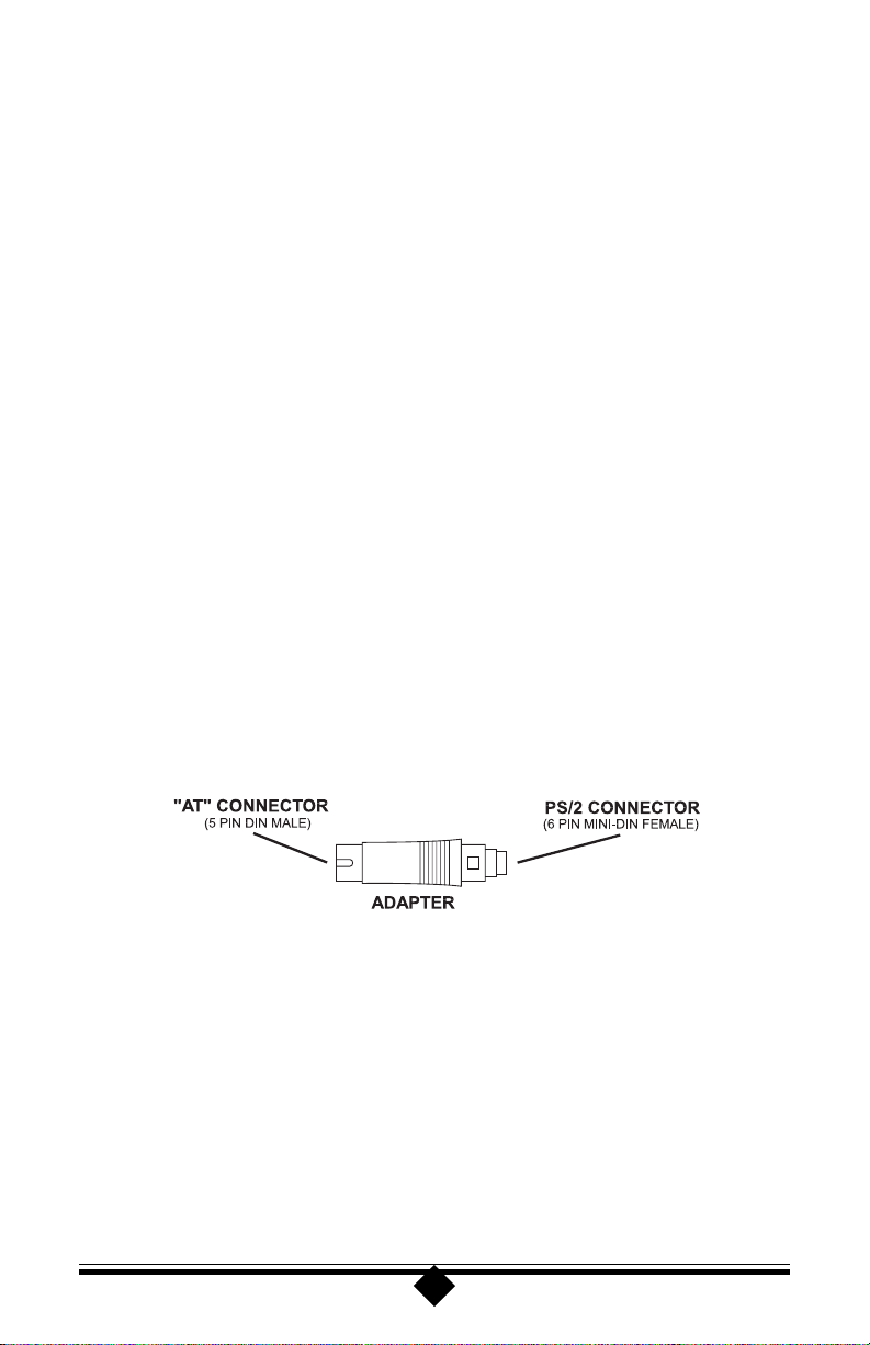
Step 2 Find the keyboard adapter included in the CameraConnect Pro package.
This device allows you to use the CameraConnect Pro in a system with
either an AT or PS/2 keyboard. The following drawing illustrates this device.
Figure 1: Ke yboard Adapter
Step 3 Find the port where your keyboard is connected to your computer. Make a
note of the location of this port, then unplug the keyboard cable. If you
have an AT keyboard, see Figure 2. If you have a PS/2 keyboard, see Figure
3. In both cases the connection of the CameraConnect Pro to the printer
port is the same.
5
Page 6
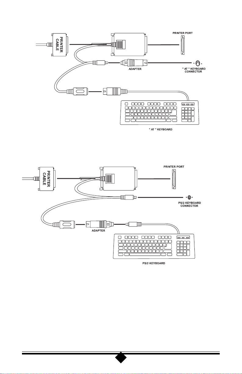
Figure 2: AT Keyboard Assembl y Diagram
Figure 3: PS/2 Ke yboard Assemb ly Dia gram
Notice how the adapter shown in Figure 1 is used in both of the keyboard connection
scenarios. For an AT keyboard, the adapter plugs into the computer. For a PS/2
keyboard, the adapter plugs into the keyboard cable.
Step 4 After you have completed the installation of the CameraConnect Pro, check
your work again to verify that all the connections are correct and that each
connector is firmly inserted and secure.
6
Page 7
Step 5 Reconnect the power cord you disconnected in step 1 and turn on the com-
puter. Look at the front of the CameraConnect Pro during start-up.
Do you see a green light? If the green light is on and you receive no keyboard errors,
you have correctly installed the power-tap to your keyboard. Both the keyboard and
printer pass-through cables on the CameraConnect Pro must be attached to the proper
connectors on your computer. If you do not see a green light on the front of the
CameraConnect Pro, turn off the power and check the method you used to connect
your keyboard and the keyboard adapter.
Installing the Driver and Utility Software
Windows 95 or 98
Step 1 Close any applications you may have running. Insert the installation disk
into your computer’s floppy disk drive. On the Windows taskbar, click Start. On the
Start menu, click Settings, then click Run. In the window that appears, type
A:\setup.exe
and press ENTER.
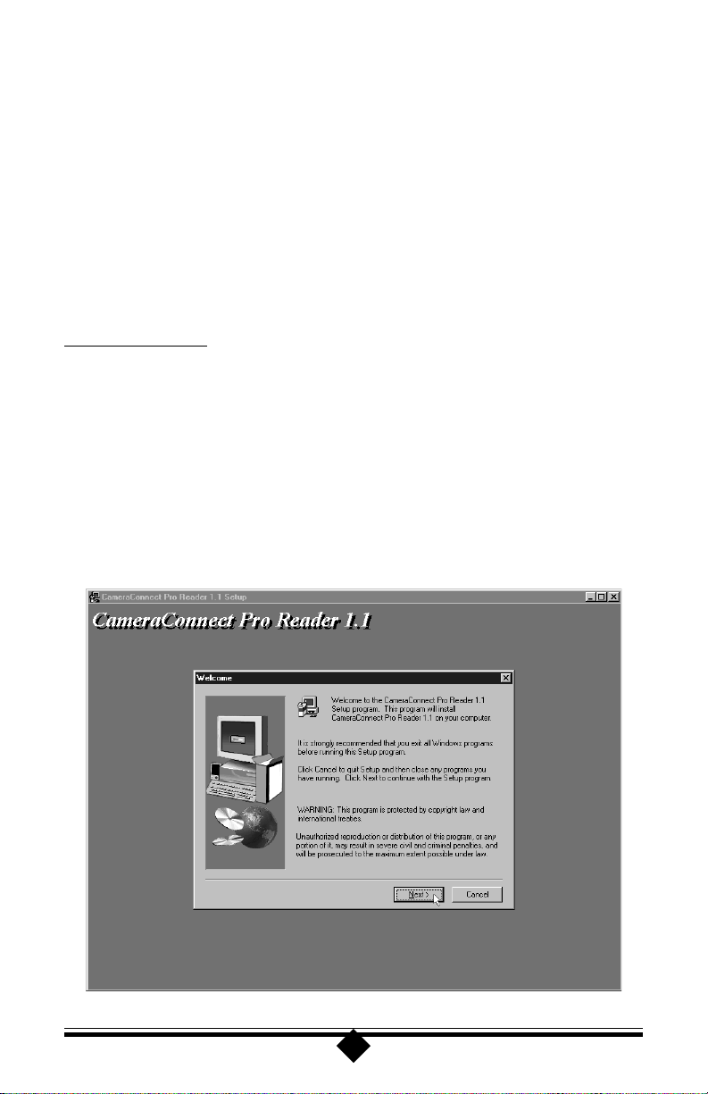
Step 2 The setup utility will display its welcome screen. Click Next.
7
Page 8
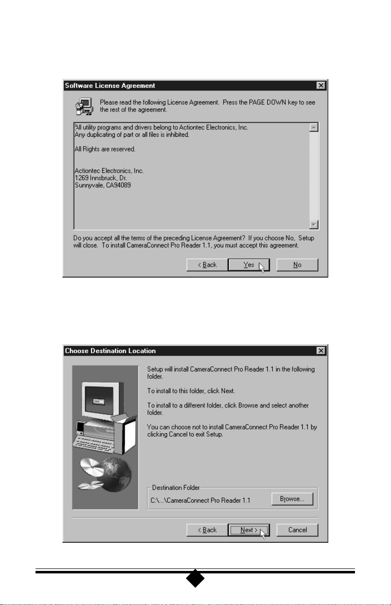
Step 3 The setup utility will display the software license agreement. You must click
Ye s to continue.
Step 4 The Choose Destination Location dialog box will appear next, suggesting
a folder where the drivers will be installed. Click Next to install in the
location displayed, or click Browse to pick a different location.
8
Page 9
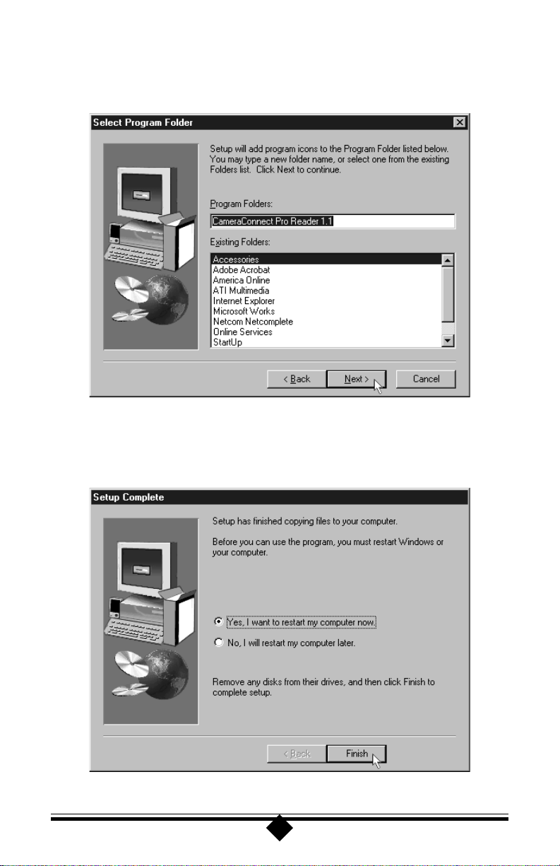
Step 5 The installation program will ask you to confirm the destination folder.
Click Next to continue.
Step 6 When the file has been copied to the location you specified earlier, click
Finish to restart your computer and enable the software.
9
Page 10
Windows NT 4.0
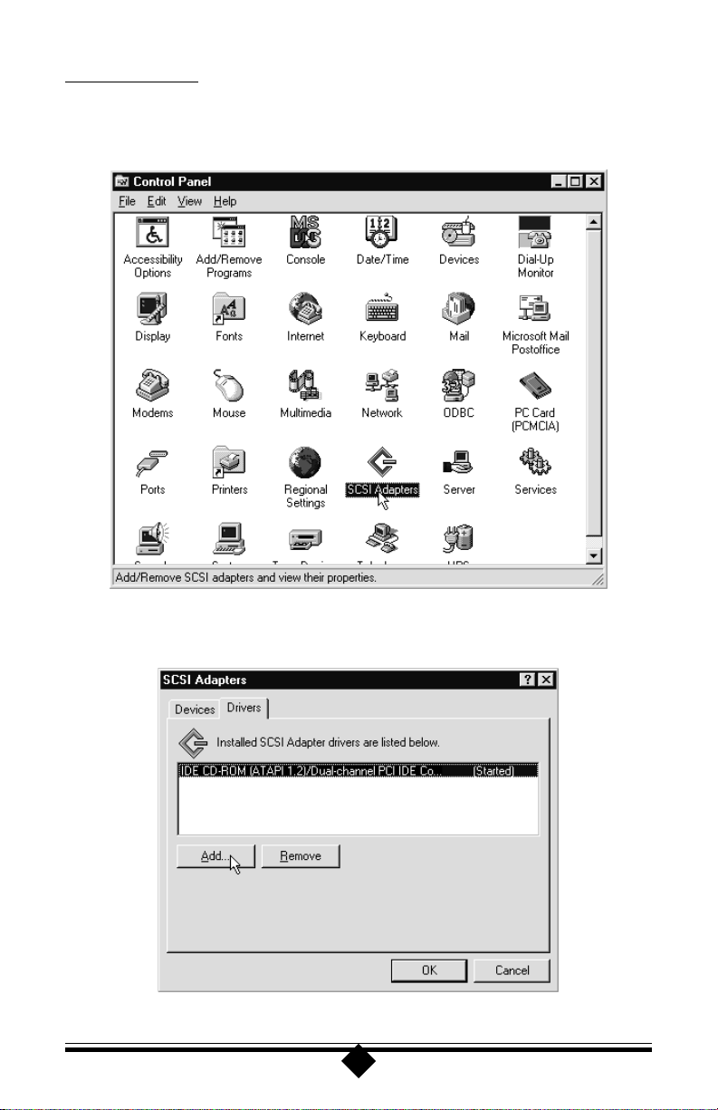
Step 1 On the Windows taskbar, click Start. On the Start menu, click Settings,
then click Control Panel. Double-click on SCSI Adapters.
Step 2 Click the Drivers tab to bring it to the front, then click the Add button.
10
Page 11

Step 3 Next, insert the CameraConnect Pro’s installation disk into the A drive and
click Have Disk.
Step 4 In the next dialog box, be sure that A:\ appears under “Copy manufacturer’s
files from:”. Click Continue.
11
Page 12

Step 5 Window NT will find the CameraConnect Pro driver on the disk. Click
OK. Windows NT 4.0 will copy and install the CameraConnect Pro driver.
Step 7 Allow Windows NT to restart the system and enable the CameraConnect
Pro.
If you had difficulty with the procedure above, place the installation disk in the A
drive. On the Start menu, click Run, then type
a:\setup.exe
and click OK. Follow the on-screen instructions.
12
Page 13

Using the CameraConnect Pro
Front P anel Functions
Figure 4: Front P anel Arrangement
Figure 4 shows the front panel layout of the CameraConnect Pro. There are two
indicator LEDs, three slots, and two eject buttons.
The indicator lights display the power-on and device-busy states of the reader. The
green LED indicates that the unit has power and is ready to function. The amber
LED shows that data is being read from or written to the device. If the unit is properly connected, the green light should always be on. The busy or amber LED light is
on only when the device is accessing a card placed in the CameraConnect Pro.
Inserting Devices into the CameraConnect Pro
The upper slot is designed to accept CompactFlash Association-compliant flash cards.
These storage devices are primarily used in digital cameras and Personal Digital Assistants (PDAs). Figure 5 illustrates the proper method of inserting these devices
into the upper slot. Remember to push the card completely into the slot so that the
CameraConnect Pro’s ejector button comes out.
Figure 5: Inserting a Compact Flash Card
13
Page 14

An inserted card will not be recognized until you perform some relevant action, such
as reading or writing to the device. When you select the CameraConnect Pro’s “Removable Disk” icon in My Computer, your computer system’s speakers will emit a
tone if a card is recognized. If a card is not recognized, an error message will be
displayed.
To eject a card, press the ejector button into the case. This will allow the CompactFlash Card to be easily removed by hand.
The lower slot is designed to accept PCMCIA ATA Flash Cards. It will not work
with any other type of Flash Card, such as Linear Flash Cards, or with non-flash
PCMCIA cards. The reader does not recognize SCSI Cards, Modem Cards, SRAM
Cards, Network Cards or other non-ATA Flash cards. If you attempt to access these
cards, a “device not ready” error message will be displayed. With certain types of
PCMCIA cards, the system will cease responding altogether.
ATA type Flash Cards will not be recognized until you read or write to the device.
When you select the CameraConnect Pro in My Computer, your computer system
will sound a ‘beep’ if the card is recognized. Figure 6 illustrates the proper insertion
of these devices in the lower slot.
Figure 6: Inserting a PCMCIA AT A Flash Car d
Like CompactFlash cards, PCMCIA ATA Cards are also polarized and can only be
inserted in the correct orientation. Remember to push the card completely into the
slot so that the eject button comes out. To release the card, press the eject button into
the case. This will allow the PCMCIA ATA Flash Card to be easily removed by hand.
The small slot in the middle of the CameraConnect Pro’s front panel is used for
SSFDC or “SmartMedia” Devices. These cards are commonly used in modern digital
cameras. The CameraConnect Pro has the hardware necessary to automatically de-
14
Page 15

tect and configure itself to use these devices.
Figure 7: Inserting an Smart Media (SSFDC) Device
Figure 7 shows the correct way to insert an SSFDC device into the CameraConnect
Pro. Notice that the gold pads are facing up. If you attempt to insert the device with
the gold pads facing down, the device will not be recognized by the CameraConnect
Pro.
Note: Insert only one card at a time into the CameraConnect Pro. If two or more
cards are inserted at the same time, none of them will work.
Formatting a Card or Smart Media (SSFDC) Device
Although your Flash Card or SSFDC Device will probably be formatted when you
purchase it, there may be times when you will need to reformat it. Like all other types
of storage media, a Flash Card or SSFDC Device must be formatted before you can
store information on it. This section outlines the procedure for formatting a device
using your operating system and the CameraConnect Pro.
Note: If you are using Windows NT, format cards using the Windows NT FAT
option. Otherwise the card may be unreadable by a computer running a
non-Windows NT operating system.
Step 1 To format a device using the CameraConnect Pro, first insert the card into
the correct slot. Refer to Figure 5, 6, or 7 (depending on the type of card
you are using) for the proper orientation of the card when inserting it into
the CameraConnect Pro.
Remember that ATA Flash Cards and Compact Flash Cards are designed so that they
will not go completely into the slot if inserted upside down. Smart Media (SSFDC)
cards must be inserted with the gold pads facing up as shown in Figure 7. If you
insert this type of card with the gold pads facing down, the card will not be recognized by the CameraConnect Pro.
15
Page 16

Step 2 Double-click the My Computer icon on the Windows desktop as shown
below.
Step 3 The CameraConnect Pro will be identified as a Removable Drive and a
drive letter will be assigned to it in My Computer. Click on its Removable
Drive icon to select it as shown below. Do not double-click the icon.
16
Page 17

Step 4 From the File menu, choose Format.
Step 5 The Format dialog box will appear. You can perform a “full format” or
select options such as Quick (erase.) Below is the Format dialog box for
Windows 98. Windows 95 displays a slightly different dialog box but the
options offered will be the same. Click the Start button in this dialog box to
begin formatting.
Note: Do not use the format function on a computer running Windows NT 4.0.
Computers running other operating systems may not be able to read cards
formatted under Windows NT 4.0.
17
Page 18

Viewing, Writing, and Copying Files
Use My Computer or Windows Explorer to gain access to the files contained on your
flash cards. When the CameraConnect Pro is installed, it is assigned a drive letter like
any other disk drive in your system. You may write to and copy files from your ATA
Flash Cards, Compact Flash Cards, and SmartMedia Devices using standard Windows drag-n-drop copy.
Menu based commands and drive utilities like Scandisk work with the CameraConnect Pro in the same way as with any other drive that appears in My Computer.
Remember, however, that the CameraConnect Pro will not detect a card placed in
one of the slots until you access the device through its drive letter. Once the CameraConnect Pro is accessed, it will read the information on the card and display the files
on screen. It will not automatically detect a card when one is inserted or removed. In
this way, the CameraConnect Pro behaves in much the same way as your floppy disk
drive.
Because it does not remain in its active state all the time, the CameraConnect Pro to
coexist with other peripherals on the parallel port. See “Using the CameraConnect
Pro with Other Parallel Port Devices” for help.
Using The CameraConnect Pro With Other Parallel Port Devices
The CameraConnect Pro’s driver and utility program allow it to share the system
printer port with other devices. However, this does not mean that the other devices
can or will share the printer port. Granted, the parallel port is designed for printers
and there is usually only one printer installed at a time. With this in mind, printer
manufacturers usually are not concerned with any additional, non-printing devices
that might be installed on a parallel port. Listed below are some guidelines for using
the CameraConnect Pro with other peripherals attached to your parallel port.
Printers
The CameraConnect Pro will coexist with most printers available on the market
today. This is also true of older, outdated printers like 9-pin dot matrix printers.
Newer printers with enhanced capabilities may include memory resident programs
which run in the background. These programs can be recognized by looking to the
Windows Taskbar in the lower right-hand corner of the desktop screen. An icon will
be visible that shows the program is active.
Figure 8: Windows Taskbar
18
Page 19

Some resident programs may be shown as minimized applications on the taskbar.
These programs constantly interrogate the printer port and can prevent the CameraConnect Pro from operating. Printers that have residant programs are generally multifunction inkjet printers that have faxing and scanning functions. Some laser printers may also include this type of resident program. They monopolize the port making
it unavailable to other applications.
In order to use the CameraConnect Pro with these printers, you will need to close the
resident printer program. Locate the program’s icon in the lower right hand corner of
the Windows desktop screen. (See Figure 9.) Click once on the icon. There will be an
option to close, or exit, on the menu that appears. Click once on either of these
listings and the program should close.
If you want to use the advanced features of your printer after you have copied the files
from your Flash Card, you can reactivate the printer’s resident program through the
Start-Programs menu. It will be listed in your printer’s program folder.
Other External Devices
The CameraConnect Pro will work with most external parallel devices. The rule to
remember is that only one peripheral device can use the printer port at any one time.
If you have another external device connected to the printer port, make sure it is not
transferring data when you are using the CameraConnect Pro. Trying to use two
devices at once will have unpredictable results which may include Windows becoming non-responsive, making it necessary to restart your computer.
19
Page 20

Using The CameraConnect Pro Utility
When you load the CameraConnect Pro Drivers in Windows 95 or Windows 98, a
utility program is also installed. This utility provides some useful information about
the CameraConnect Pro’s installation parameters and the status of any cards which
are installed in it.
The CameraConnect Pro Utility can be started from Programs menu. On the Start
menu, click Programs, click CameraConnect Pro, then click CameraConnect Utility.
The utility will display the dialog box shown below.
Figure 9: The CameraConnect Utility Screen
Three sections of information are provided in the utility’s dialog box. The first block
gives PC Parallel Port detection information. The port address indicates which LPT
Port the CameraConnect Pro is connected to. The default LPT addresses are listed
below.
0x378 LPT1:
0x278 LPT2:
0x3BC LPT3:
20
Page 21

The Reader Status and Setting block shows the CameraConnect Pro’s current operational mode, as well as indicating if a card is present or the sockets are empty. The
parallel port modes displayed are SPP (standard), PS/2 (simple bidirectional), EPP
(enhanced parallel port), and ECP (extended capabilities port). The PS/2 listing will
be shown by a system with a bidirectional printer port configured in standard mode.
SPP mode is a standard unidirectional printer port. EPP and ECP are the two other
modes for parallel ports.
EPP mode is the preferred setting for the CameraConnect Pro. Your printer port
mode can be configured through your system BIOS setup utility. See your computer
system user’s manual for information on setting your printer port mode through the
system BIOS setup.
Note: Setting your printer port to EPP or ECC/EPP mode will also facilitate the
best transfer speeds in most cases.
The Card Information block will show the type of card inserted (SmartMedia or
ATA Flash/CF), its size in Megabytes, and if write protection is enabled. The card
you have may not offer this feature and the Card Write protection area will always
show “No.”
Remember that the utility screen will not automatically update when you insert or
remove a card from one of the CameraConnect Pro’s slots. If you insert or remove a
card, be sure to click on the Refresh button to update the screen.
21
Page 22

Error Messages and Troubleshooting
This section lists some common error messages and operational problems that might
be encountered when using the CameraConnect Pro and offers suggestions for their
correction. If you have difficulties when trying to share the printer port with several
external devices, it is suggested that you obtain a separate parallel port card for some
of your devices. Generally, two external parallel port peripherals can share the same
port with little difficulty but if there are three, four, or five external devices on one
printer port, problems are much more likely. The only solution in this case is to
remove as many devices as possible and move them to a separate printer port.
Some Common Error Messages
The above error message is likely to be issued when the card placed in the CameraConnect Pro is not recognized. This message can also be seen when there is no card in
the CameraConnect Pro. Likely causes are: The card is not formatted, has no CIS
(Card Information Structure), or the card is not an ATA Flash Card (the CameraConnect Pro will only operate with ATA Flash, Compact Flash, or SmartMedia devices).
The message shown above is issued by Windows NT 4.0 when a SmartMedia device
is removed from the CameraConnect Pro after the copy process appeared to end. The
‘busy’ light had stopped flashing and the copy process looked to be finished. However, Windows NT had not finished writing to the device. When using Windows NT
4.0, wait 10 seconds after the ‘busy’ light stops flashing before removing a device
from the CameraConnect Pro.
22
Page 23

Some Common Problems
When I insert a card into the CameraConnect Pro, nothing happens.
You must access the CameraConnect Pro through Windows My Computer or Windows Explorer before you can view or copy files.
When I double-click the Remo v able Drive icon in My Computer, I can
see my picture files. Ho w do I vie w them with my picture program?
You can copy your files into your hard drive and open them from there, or you can
open them directly from the card. Just specify the removable drive as the source for
your files in your application’s Open dialog box. They will load directly from the
CameraConnect Pro into your program.
When I insert a SmartMedia Card into the CameraConnect Pro, I can’t
read the files. Windows returns a “not accessib le” error.
See “Inserting Devices into the CameraConnect Pro” for the correct way to insert an
SSFDC device.
When I copy files from the CameraConnect Pro, my printer pauses
printing for a few seconds.
When you access the CameraConnect Pro, be sure no other device is using the printer
port. See ”Using The CameraConnect Pro With Other Parallel Port Devices” for
help.
When I try to use a card formatted by a computer running Windows
NT 4.0, my camera ref ormats it.
Do not format cards in Windows NT 4.0. Cards formatted in Windows NT 4.0 will
not be readable in other operating systems and may be automatically reformatted by
certain cameras and other devices.
I installed the CameraConnect Pro in my office system, but it is not
listed as a drive in My Computer.
If you are connected to a network, be sure you have enough drive letters assigned to
your system. See your MIS department or System Administrator for help in modifying your lastdrive statement.
23
Page 24

The CameraConnect Pro will not install. (No Drive Letter Assigned)
You may not have enough drive letters available to your system. In Windows 95 or
Windows 98, right-click the My Computer icon on the desktop and choose Proper-
ties from the menu that appears. In the System Properties window, click on the
Device Manager tab. Double-click the Disk Drives icon in the device tree to show
what drives are installed in the system. Click once on Parallel Flash Drive to select it,
then click Properties to display the Properties Window. Now click the Settings tab to
access the drive letter information. The information below should be displayed.
At the bottom of the window there will be an option selection box for Reserved drive
letters. Click once on the Start drive letter box as shown in the picture. The start
drive letter must be greater than the total number of disk drives and CD-ROM
drives in your system. After you have set the start drive letter, set the End drive letter
to Z. Restart your system and check My Computer. Your CameraConnect Pro should
be listed as a Removable Drive.
Note: Never select “Int 13 unit”. Your system will stop responding.
You may need to do a “clean” installation of the CameraConnect Pro software in your
system. See Appendix A for instructions on how to uninstall the software. When the
softwaere has been uninstalled, remove the parallel port from the Device Manager
listing (it can be found under the heading “Ports.”) Shut down, rather than restart,
your computer, then turn it back on again and reinstall the software.
24
Page 25

The green light on the CameraConnect Pro never comes on and the
computer’s light is also off.
If both the computer system’s power light and the green light on the CameraConnect
Pro are off, you should turn off the power and disconnect the CameraConnect Pro. If
your system is functioning normally, not be allowing power sharing from the keyboard connector. Contact your computer’s manufacturer for assistance.
25
Page 26

Appendix A: Uninstalling the CameraConnect Pr o
Uninstalling in Windows 95 or Windows 98
Step 1 On the Start menu, click Settings, then click Control Panel. In Control
Panel, double-click Add/Remove Programs.
Step 2 Click CameraConnect Pro Reader to select it. Then click Add/Remove.
Step 3 A warning message will ask you to confirm the removal of the CameraCon-
nect Pro Reader from the system. Click the Yes button.
Step 4 After the files have been removed, click OK.
26
Page 27

Windows NT 4.0
Step 1 On the Start menu, click Settings, then click Control Panel. In Control
Panel, double-click on SCSI Adapters.
Step 2 Click on the Drivers tab. In the list, click to select CameraConnect Pro
Reader. Then click Remove.
Step 3 A warning message will ask you to confirm the removal of the CameraCon-
nect Pro Reader from the system. Click the Yes button.
Step 4 The driver will be removed from your system. Click Cancel.
27
Page 28

Appendix B: Technical Reference
External Port Connectors
Figure 10: Printer (LPT) P ort Connector - Front View
Figure 11: AT Keyboard Connector - Fr ont View
Figure 12: PS/2 Keyboar d Connector - Fr ont View
28
Page 29

CAUTION: CHANGES OR MODIFICATIONS NOT
EXPRESSLY APPROVED BY THE PARTY RESPONSIBLE
FOR COMPLIANCE COULD VOID THE USER’S AU-
THORITY TO OPERATE THE EQUIPMENT.
Notices
Declaration of Conformity
This equipment has been tested and found to comply with the limits for a Class B
digital device, pursuant to Part 15 of the FCC Rules. These limits are designed to
provide reasonable protection against harmful interference in a residential installation. This equipment generates, uses and can radiate radio frequency energy and, if
not installed and used in accordance with the instructions, may cause harmful interference to radio communications. However, there is no guarantee that interference
will not occur in a particular installation. If this equipment does cause harmful
interference to radio and television reception, the user is encouraged to try to correct
the interference by one or more of the following measures:
Reorient the receiving antenna.
Increase the separation between the equipment and receiver.
Connect the equipment into an outlet on a circuit different from that to which the
receiver is connected.
Consult the dealer or an experienced radio/TV technician for help.
Notice for the European Community
The product CameraConnect Pro (PC805) complies with the European Directives
89/336/EEC, “Electromagnetic Compatibility” (EMC) and 73/23/EEC “Low Voltage Directive”.
29
Page 30

303132
Page 31

Page 32

Page 33

33
 Loading...