

Toshiba PA3541U-2PRP dynadock VGA, PA3542U-2PRP dynadock DVI, dynadock User Manual

User’s Manual
dynadock™

dynadock™
Contents
Introduction . . . . . . . . . . . . . . . . . . . . . . . . . . . . . . . . . . . . . . . . . . . . . . . 7
Features . . . . . . . . . . . . . . . . . . . . . . . . . . . . . . . . . . . . . . . . . . . . . . . . 7
Front panel . . . . . . . . . . . . . . . . . . . . . . . . . . . . . . . . . . . . . . . . . . . . . . 8
Back panel . . . . . . . . . . . . . . . . . . . . . . . . . . . . . . . . . . . . . . . . . . . . . . 9
Package contents . . . . . . . . . . . . . . . . . . . . . . . . . . . . . . . . . . . . . . . . 10
System Requirements . . . . . . . . . . . . . . . . . . . . . . . . . . . . . . . . . . . . 10
Assembly . . . . . . . . . . . . . . . . . . . . . . . . . . . . . . . . . . . . . . . . . . . . . . . . 11
Installation . . . . . . . . . . . . . . . . . . . . . . . . . . . . . . . . . . . . . . . . . . . . . . . 13
Connecting the dynadock to the Computer . . . . . . . . . . . . . . . . . . . . 13
Installing the Drivers . . . . . . . . . . . . . . . . . . . . . . . . . . . . . . . . . . . . . . 14
Uninstalling. . . . . . . . . . . . . . . . . . . . . . . . . . . . . . . . . . . . . . . . . . . . . . . 22
Uninstalling - Windows Vista Operations . . . . . . . . . . . . . . . . . . . . . . 22
Uninstalling - Windows XP Operations. . . . . . . . . . . . . . . . . . . . . . . . 24
Using the dynadock . . . . . . . . . . . . . . . . . . . . . . . . . . . . . . . . . . . . . . . . 26
USB 2.0 Ports (Front and Back Panel). . . . . . . . . . . . . . . . . . . . . . . . 26
Ethernet Port (Back Panel). . . . . . . . . . . . . . . . . . . . . . . . . . . . . . . . . 26
Serial Port (Back Panel) . . . . . . . . . . . . . . . . . . . . . . . . . . . . . . . . . . . 27
Front Panel Audio Port (Microphone) . . . . . . . . . . . . . . . . . . . . . . . . . 28
Front Panel Audio Port (Headphones or Speakers) . . . . . . . . . . . . . . 28
Video Port (VGA or DVI). . . . . . . . . . . . . . . . . . . . . . . . . . . . . . . . . . . 32
How Standby/Sleep or Hibernate Mode Affects Devices Attached
to the dynadock . . . . . . . . . . . . . . . . . . . . . . . . . . . . . . . . . . . . . . . . 37
Disconnecting the dynadock . . . . . . . . . . . . . . . . . . . . . . . . . . . . . . . . 39
Eject Dock . . . . . . . . . . . . . . . . . . . . . . . . . . . . . . . . . . . . . . . . . . . . . 39
Eject Dock and Sleep . . . . . . . . . . . . . . . . . . . . . . . . . . . . . . . . . . . . . 40
Eject by use of command line. . . . . . . . . . . . . . . . . . . . . . . . . . . . . . . 41
Removing Settings . . . . . . . . . . . . . . . . . . . . . . . . . . . . . . . . . . . . . . . 41
Select Audio Device . . . . . . . . . . . . . . . . . . . . . . . . . . . . . . . . . . . . . . 44
Specifications. . . . . . . . . . . . . . . . . . . . . . . . . . . . . . . . . . . . . . . . . . . . . 45
EN-2 User’s Manual

Regulatory Compliance
FCC Information
Product Name: dynadock
Model number: PA3541*, PA3542*
FCC notice “Declaration of Conformity Information”
This equipment has been tested and found to comply with the limits for a
Class B digital device, pursuant to part 15 of the FCC rules. These limits
are designed to provide reasonable protection against harmful interference
in a residential installation. This equipment generates, uses and can radiate
radio frequency energy and, if not installed and used in accordance with the
instructions, may cause harmful interference to radio communications.
However, there is no guarantee that interference will not occur in a
particular installation. If this equipment does cause harmful interference to
radio or television reception, which can be determined by turning the
equipment off and on, the user is encouraged to try to correct the
interference by one or more of the following measures:
■ Reorient or relocate the receiving antenna.
■ Increase the separation between the equipment and receiver.
■ Connect the equipment into an outlet on a circuit different from that to
which the receiver is connected.
■ Consult the dealer or an experienced radio/TV technician for help.
WARNING: Changes or modifications made to this equipment, not
expressly approved by TOSHIBA or parties authorized by TOSHIBA could
void the user’s authority to operate the equipment.
FCC Conditions
This equipment has been tested and found to comply with Part 15 of the
FCC Rules. Operation is subject to the following two conditions:
(1) This device may not cause harmful interference
(2) This device must accept any interference received. Including
interference that may cause undesired operation.
Contact
Address: TOSHIBA America Information Systems, Inc.
9740 Irvine Boulevard
Irvine, California 92618-1697
Telephone: (949) 583-3000
User’s Manual EN-3
dynadock™
EU Declaration of Conformity
TOSHIBA declares, this product conforms to the following Standards:
Supplementary
Information:
This product is carrying the CE-Mark in accordance with the related
European Directives. Responsible for CE-Marking is TOSHIBA Europe,
Hammfelddamm 8, 41460 Neuss, Germany.
“This product complies with the requirements of the
EMC Directive 89/336/EEC and/or the Low Voltage
Directive 73/23/EEC.”
WEEE Information
For EU (European Union) member users: According to the WEEE (Waste
electrical and electronic equipment) Directive, do not dispose of this
product as household waste or commercial waste. Waste electrical and
electronic equipment should be appropriately collected and recycled as
required by practices established for your country. For information on
recycling of this product, please contact your local authorities, your
household waste disposal service or the shop where you purchased the
product.
Safety Instructions
Always read the safety instructions carefully:
■ Keep this User’s Manual for future reference
■ Keep this equipment away from humidity
■ If any of the following situations arise, get the equipment checked by a
service technician:
■ The equipment has been exposed to moisture.
■ The equipment has been dropped and damaged.
■ The equipment has obvious sign of breakage.
■ The equipment has not been working well or you cannot get it to
work according to the User’s Manual.
EN-4 User’s Manual

Copyright Statement
No part of this publication may be reproduced in any form by any means
without the prior written permission. Other trademarks or brand names
mentioned herein are trademarks or registered trademarks of their
respective companies.
Disclaimer
Information in this document is subject to change without notice. The
manufacturer does not make any representations or warranties (implied or
otherwise) regarding the accuracy and completeness of this document and
shall in no event be liable for any loss of profit or any commercial damage,
including but not limited to special, incidental, consequential, or other
damage.
January 2007, Rev2.0
Trademarks
Intel, Intel Core, Pentium and Celeron are trademarks or registered
trademarks of Intel Corporation.
Microsoft, Microsoft Office, Windows and Windows Vista are either
registered trademarks or trademarks of Microsoft Corporation in the United
States and/or other countries.
AMD, AMD K6, Athlon and Duron are trademarks of Advanced Micro
Devices Incorporated.
Ethernet is a registered trademark and Fast Ethernet is a trademark of
Xerox Corporation.
Adobe and Reader are either registered trademarks or trademarks of
Adobe Systems Incorporated in the United States and/or other countries.
Other trademarks and registered trademarks not listed above may be used
in this manual.
Precautions
The Fn + F5 functionality detailed in the electronic User’s Guide for your
TOSHIBA computer only controls the internal video controller of your
computer.
The TOSHIBA dynadock utilizes an advanced video graphics controller to
display the video on the external monitor connected to it. However, due to
USB 2.0 transfer speed limitations, some or all portions of DVD playback
may appear slow or choppy. This is not a malfunction of the dynadock.
Move the video playback from the external monitor to your computer
display for optimal video performance when viewing DVDs.
User’s Manual EN-5

dynadock™
The playback of DVD is not supported in the mirror mode.
The 3D screensavers (3D FlowerBox and so on) do not work in either
mirror or extended mode.
This product does not support 3D programs.
Unable to enter full screen DOS mode in the mirror mode.
Google Earth does not work in the mirror mode.
The video driver passes 24-bit data to the device if you have selected 32-bit
color quality. This is for more efficient data transfer.
When recording audio, it is recommended that you manually configure the
microphone volume settings.
Precautions for Windows Vista™ only
The dynadock only supports the mirror mode for display.
When the dynadock is connected, the screens of your computer and
external device will become BASIC mode automatically. The screen of your
computer will return to AERO mode automatically when the dynadock is
disconnected.
The games in OpenGL such as Quake3 will not be supported in the mirror
mode. If you want to play these kinds of games, we suggest you disconnect
the dynadock.
USB, CPU resources and other devices may be affected when playing
movies or transferring large amounts of data via the dynadock
The external monitor will not turn off automatically by the operating system
power management.
The sound may be distorted or delayed when you play MIDI/MPG files. If
it’s a MIDI file, please try to change your media player visualization
settings. If it’s a MPG file, we suggest you play it without connecting the
dynadock.
.
EN-6 User’s Manual

Introduction
The Toshiba dynadock with Video utilizes a single USB port to extend your
computer to your desktop environment with one easy connection, enabling
you to connect all of your peripherals, including six USB devices, Ethernet
network, serial device, headphones, speakers and microphone plus an
external monitor and digital audio equipment. It’s ideal for the computers
having extra connectivity demands.
The upright slim design of the dynadock saves your desktop space while
the two USB ports on the front panel give you easy accessibility. The
dynadock is hot swappable; you can add or remove any device without
rebooting the computer. With all these features, the dynadock is a perfect
accessory whether you are at home or at the office.
With the video port, your computer can be connected to an external
monitor, LCD or projector at native display resolutions of up to 1600 x 1200
pixels (DVI version only). The connected monitor can be configured to
either mirror your primary screen or extend (in Windows XP only) the
Windows
No more stacking windows within the confines of a single display.
An additional feature is the S/PDIF digital audio output. It directly outputs
the digital sound source from the computer to your home audio receiver
without the loss of high quality sound. If you are using 2 channel speakers
or headphones via the conventional audio port, you can still enjoy the 7.1
surround sound, which is achieved by the virtual multi-channel audio
function.
®
desktop allowing visibility of more applications at the same time.
Introduction
NOTE: The dynadock is available in two video support versions, either a
VGA video port or a DVI video port. This user manual contains information
for both versions of the dynadock. Please pay attention to and follow the
instructions for the version you have.
Features
■ Single USB plug connecting to your computer
■ Upright slim design saves desktop space
■ Easily accessible ports located on the front
■ Supports notebook-quality video on external monitor
■ VGA resolution up to SXGA (1280 x 1024), 16/32-bit color
■ DVI resolution up to UXGA (1600 x 1200), 16/32-bit color
■ Hot swappable; add or remove devices without rebooting the computer
■ Virtual 7.1 channel surround sound
■ All video and audio drivers included
User’s Manual EN-7
dynadock™
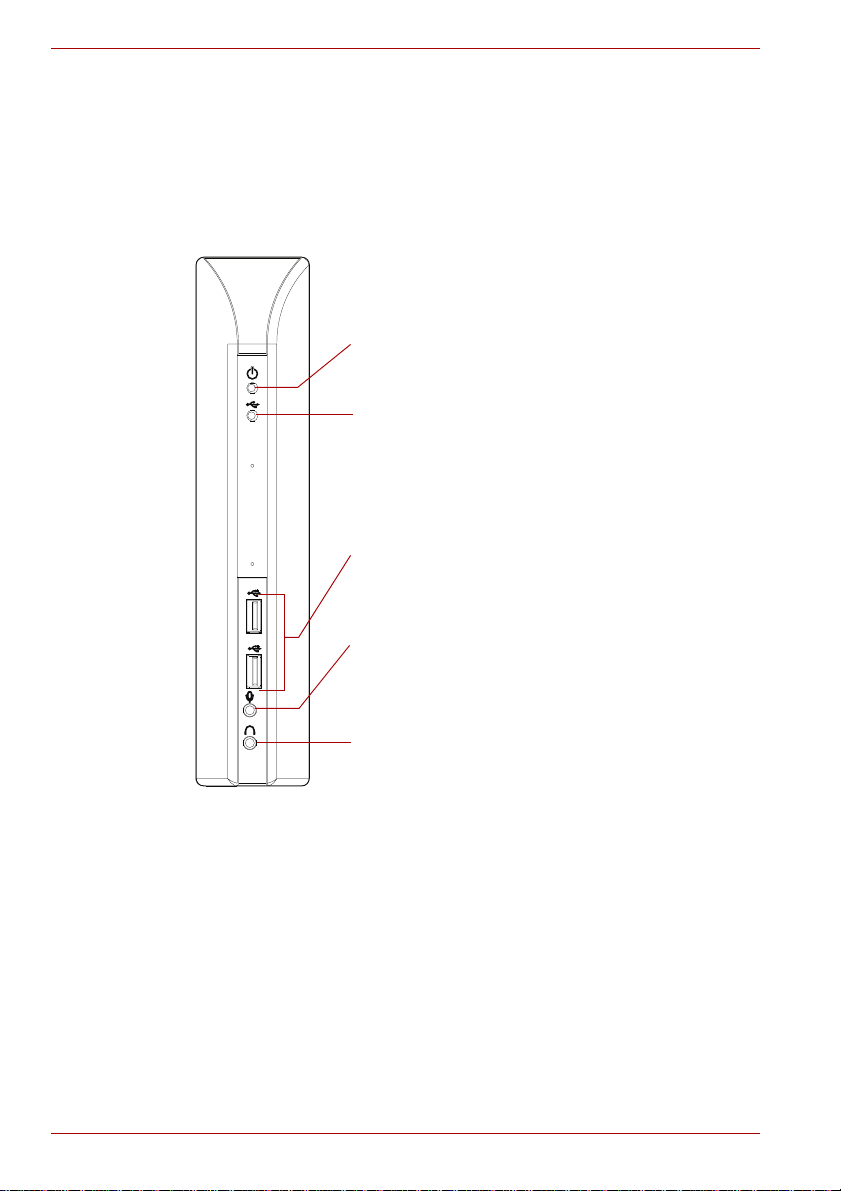
Power LED: Glows blue when the dynadock is
powered on.
USB Hub LED: Glows green when any of the six USB
ports are connected to a USB device.
2 USB 2.0 powered ports: For connection to USB
peripherals.
3.5 mm mono microphone input port: For
connection to an external mono microphone for
recording.
3.5 mm stereo audio output port: For connection to
stereo headphones or speakers.
■ Provides TOSHIBA dynadock Utility to remove all the devices at one
time
■ Power is always provided by the front USB ports, even though the
computer is off
Front panel
(Sample Illustration) Indicators and connectors on the front of the dynadock
EN-8 User’s Manual
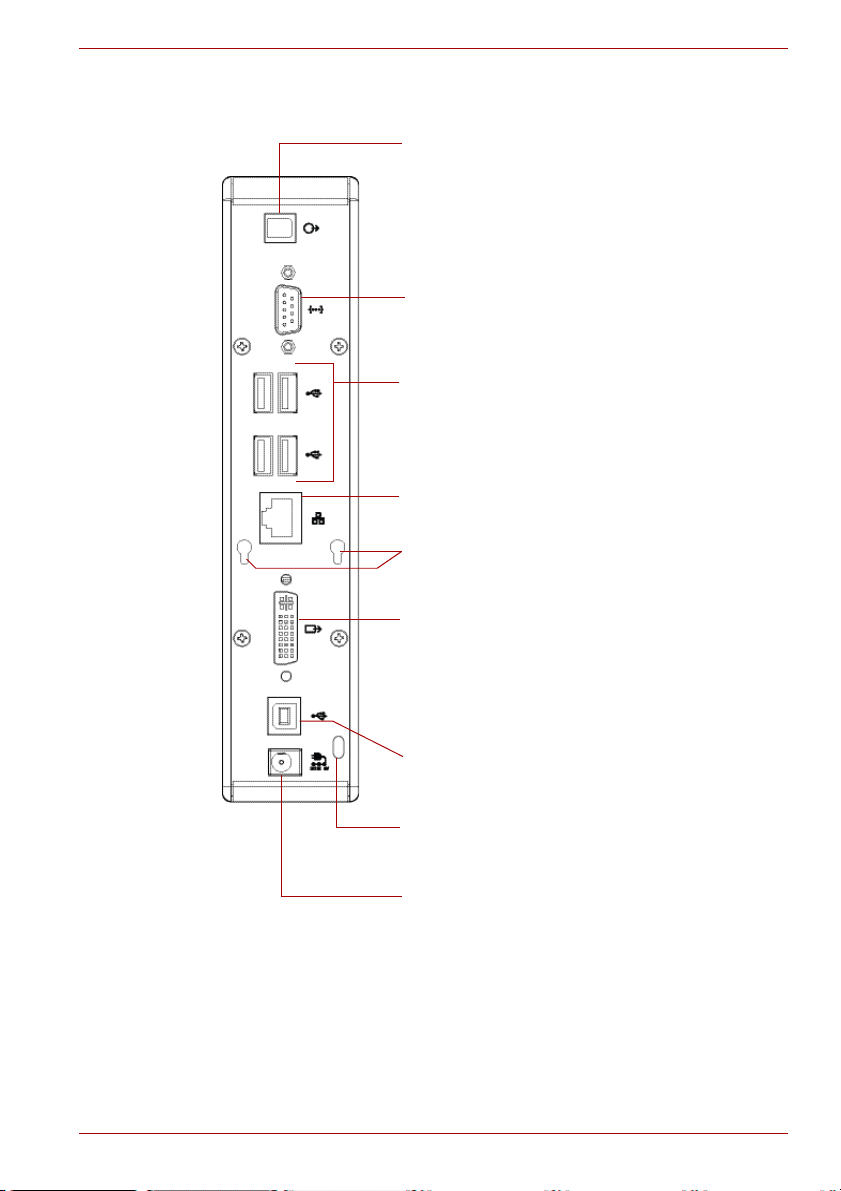
Back panel
Optical S/PDIF digital out port: Use an optical
S/PDIF cable (not provided) to connect to your
digital audio equipment, e.g., Dolby Digital
Surround Sound receiver and speaker system
To use this connection, your receiver must have
an optical S/PDIF input.
DB9 Serial port: For connection to the serial device
you want to control.
4 USB 2.0 ports (A type female connector): For
connection to USB peripherals.
10/100 Mbps Ethernet port: For connection to the
Ethernet network via a network cable (not provided).
USB port: For connection to the USB port of the
host computer.
DVI video output port: For connection to a DVI
monitor (shown).
- or VGA video output port: For connection to a VGA
monitor (not shown).
Cable Lock Slot: Allows you to connect a cable lock
to help prevent theft (not provided).
Power jack: For connection to the provided AC
adaptor. The dynadock always needs an external
power supply for operation, as it does not take
power from the USB bus.
Cable holder holes: Allows you to hook the cable
holder once all of your devices are attached.
Introduction
(Sample Illustration) Connections on the back of the dynadock
User’s Manual EN-9

dynadock™
Package contents
■ dynadock (VGA or DVI video interface)
■ Base plate
■ Cable Holder
■ USB 2.0 Cable
■ AC Power Adaptor
■ AC Power Cord/cable
■ CD (User Manual, Driver and Utility)
■ Quick Installation Guide
■ DVI to VGA video adapter (DVI version only)
System Requirements
■ 1.2GHz or higher processor. Intel Pentium/Celeron family, or AMD K6/
Athlon/Duron family, or compatible processor recommended (Core™ 2
Duo 2.0 GB or higher processor recommended for optimal video
performance)
■ 512 MB memory or higher (1 GB memory or higher recommended)
■ USB 2.0 port
■ 30 MB of available disk space
■ Windows® XP with SP2/Windows Vista™ (32-bit edition)
■ For optimal results the display resolution should be configured to
800 x 600 with 16-bit color.
EN-10 User’s Manual
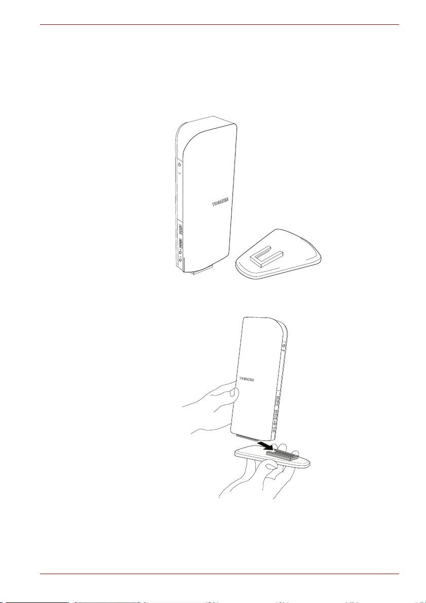
Assembly
Remove the base and dynadock from the packaging. You will need to
assemble the two pieces.
Slide the dynadock onto the base as shown below.
Assembly
(Sample Illustration) The dynadock and base before assembly
(Sample Illustration) Assembling the dynadock and base
User’s Manual EN-11
dynadock™
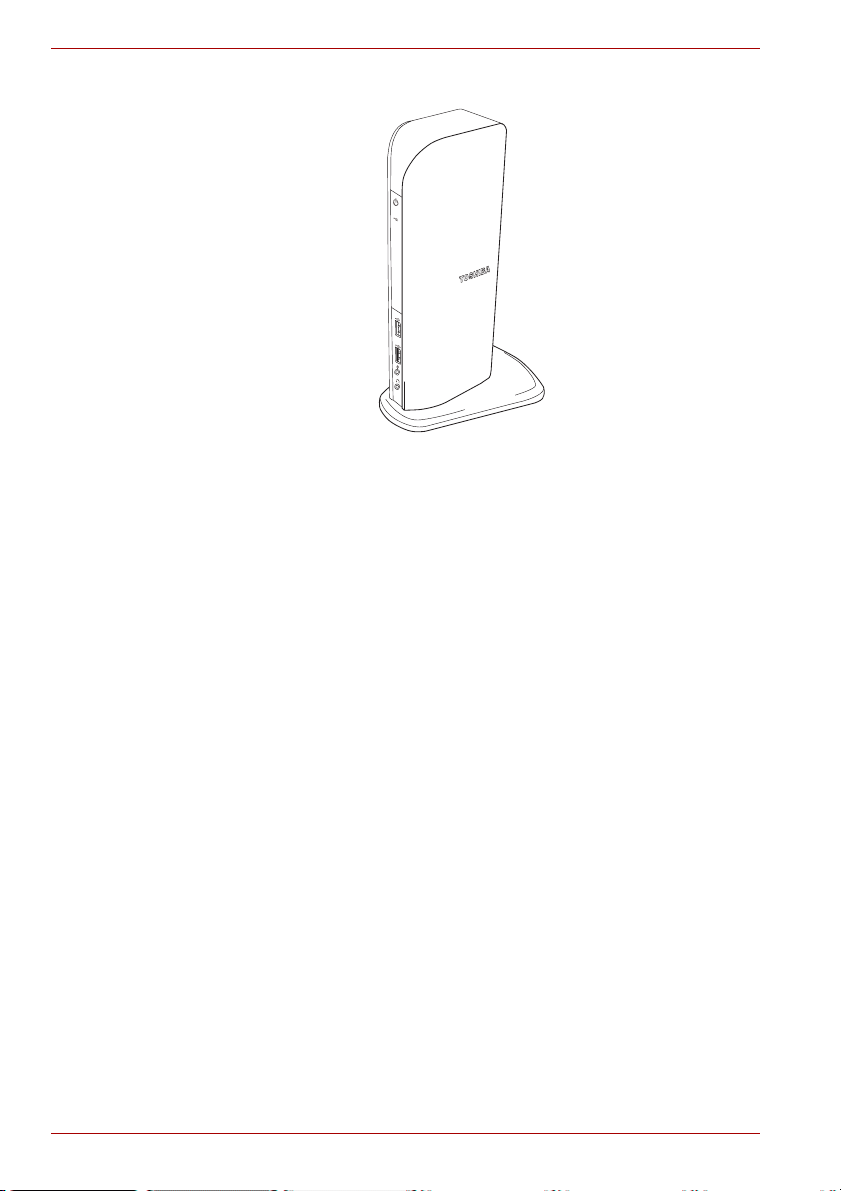
When assembled, the dynadock is a self-standing, easy to place unit.
(Sample Illustration) The assembled dynadock
EN-12 User’s Manual
Installation
Connecting the dynadock to the Computer
Before installation, it is recommended to connect the dynadock to your PC
first. Please follow the steps to connect it correctly:
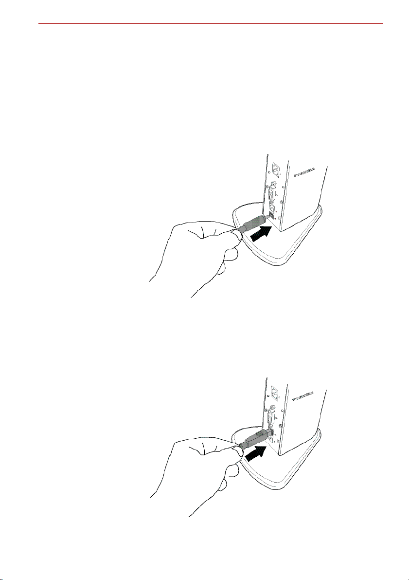
1. Plug the AC adaptor into the DC-IN on the back of the dynadock.
Installation
(Sample Illustration) Connecting the power to the dynadock
2. Connect the AC adaptor with the power cord/cable, and then connect
the power cord/cable to a live electrical outlet. The power indicator on
the front panel glows blue when the dynadock is powered on.
3. Plug the square end of the USB cable into the USB upstream connector
on the back of the dynadock.
(Sample Illustration) Connecting the USB cable to the dynadock
User’s Manual EN-13
dynadock™
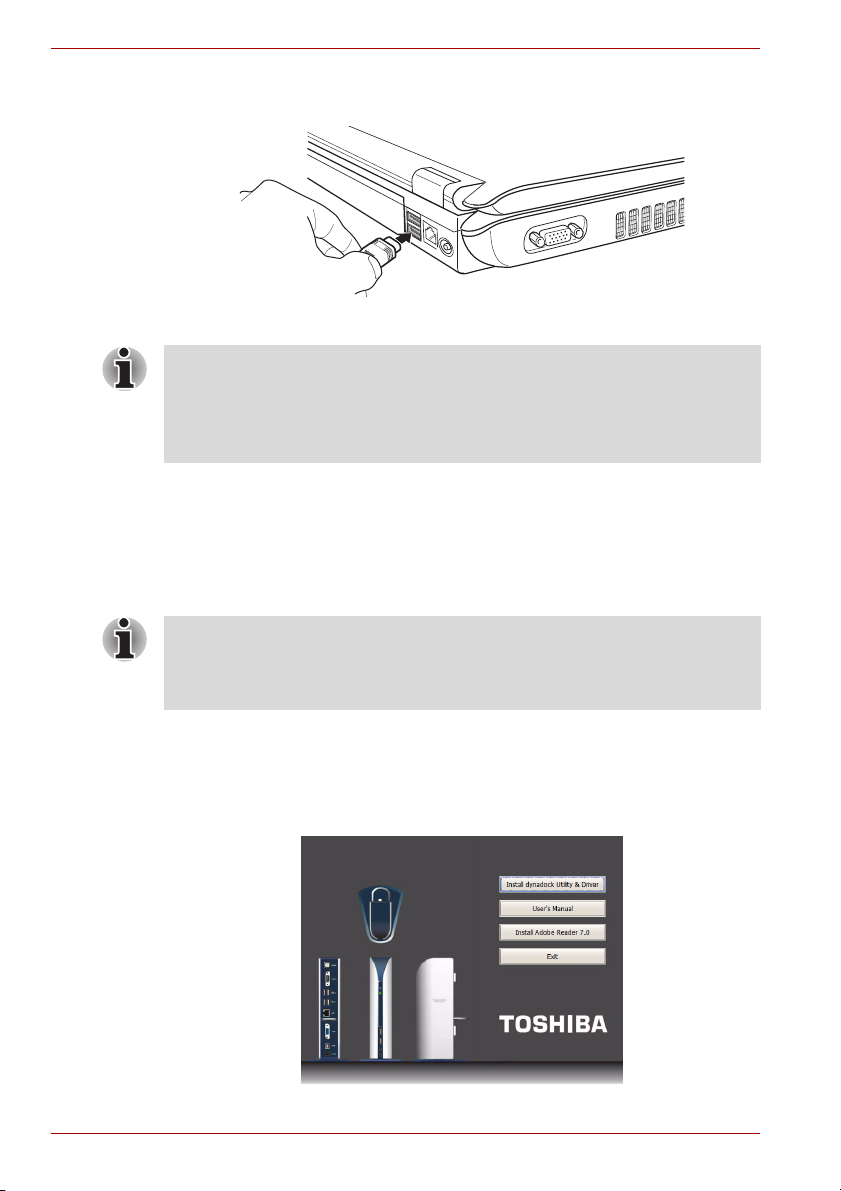
4. Plug the other end of the USB cable into an available USB 2.0 port on
your computer.
(Sample Illustration) Connecting the USB cable to your computer
NOTE: Be sure to remember which USB port is used for the driver
installation and always plug the dynadock into the same USB port,
otherwise, Windows® will treat the dynadock as a new device and ask to
install the drivers again. Only one dynadock can be operated on one PC at
a time.
5. Connect your notebook computer to a power source and turn it on. For
more information on connecting your computer to a power source, read
the documentation for your computer.
Installing the Drivers
NOTE: The following installation steps are for both Windows Vista™ and
Windows XP operating systems. Although most steps are similar, there are
some differences between the two operating systems so please follow the
steps for your operating system where indicated.
1. Insert the provided Installation CD into your optical disc drive. It will run
automatically and the dialog box will appear.
If the auto-run function is disabled on your system, the program will fail
to load automatically. Please open the disk in explorer, and double click
“AutoRun.exe”.
(Sample Illustration) Initial Screen
EN-14 User’s Manual
Installation
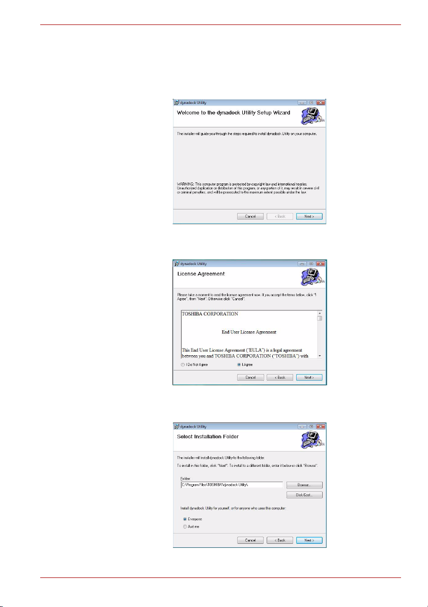
2. Click on “Install dynadock Utility & Driver”, the program will begin
installing the dynadock Utility and all drivers necessary for the
dynadock device. Follow the screen directions to finish the utility
installation.
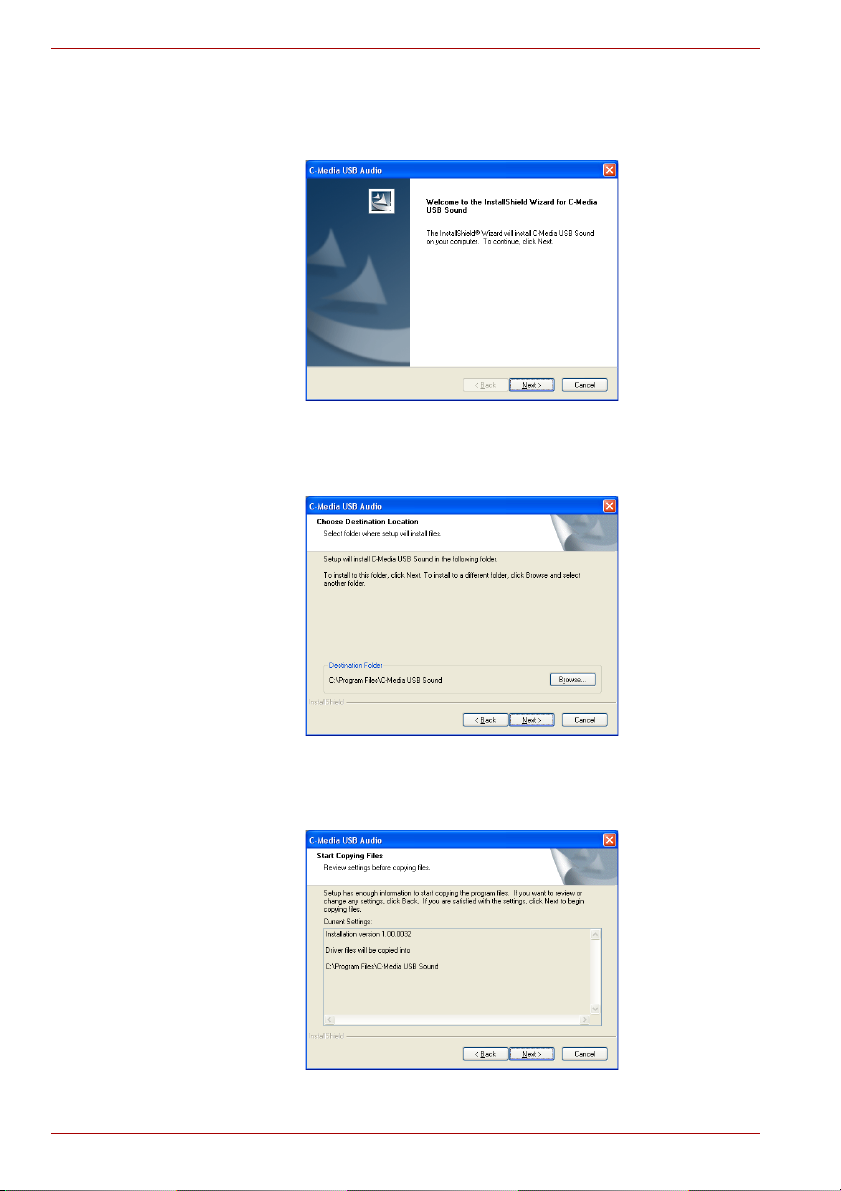
Step 1: When the welcome screen appears, click Next.
(Sample Image) Welcome screen
Step 2: Select “I Agree” and click Next.
(Sample Illustration) License Agreement screen
Step 3: Choose the destination folder.
(Sample Image) Choose Destination Location screen
User’s Manual EN-15
dynadock™
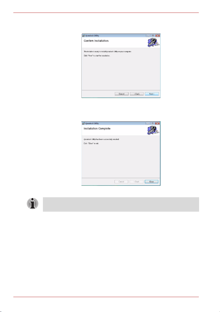
Step 4: Click Next to start the installation. This may take several
minutes.
(Sample Image) Ready to Install screen
Step 5: Click Close when the “Installation Complete” dialog box shown
below appears.
(Sample Image) Finish screen
NOTE: There are slight differences in the installation between Windows
Vista and Windows XP. Please follow the steps for your operating system.
EN-16 User’s Manual
Installation
Windows Vista Operations:
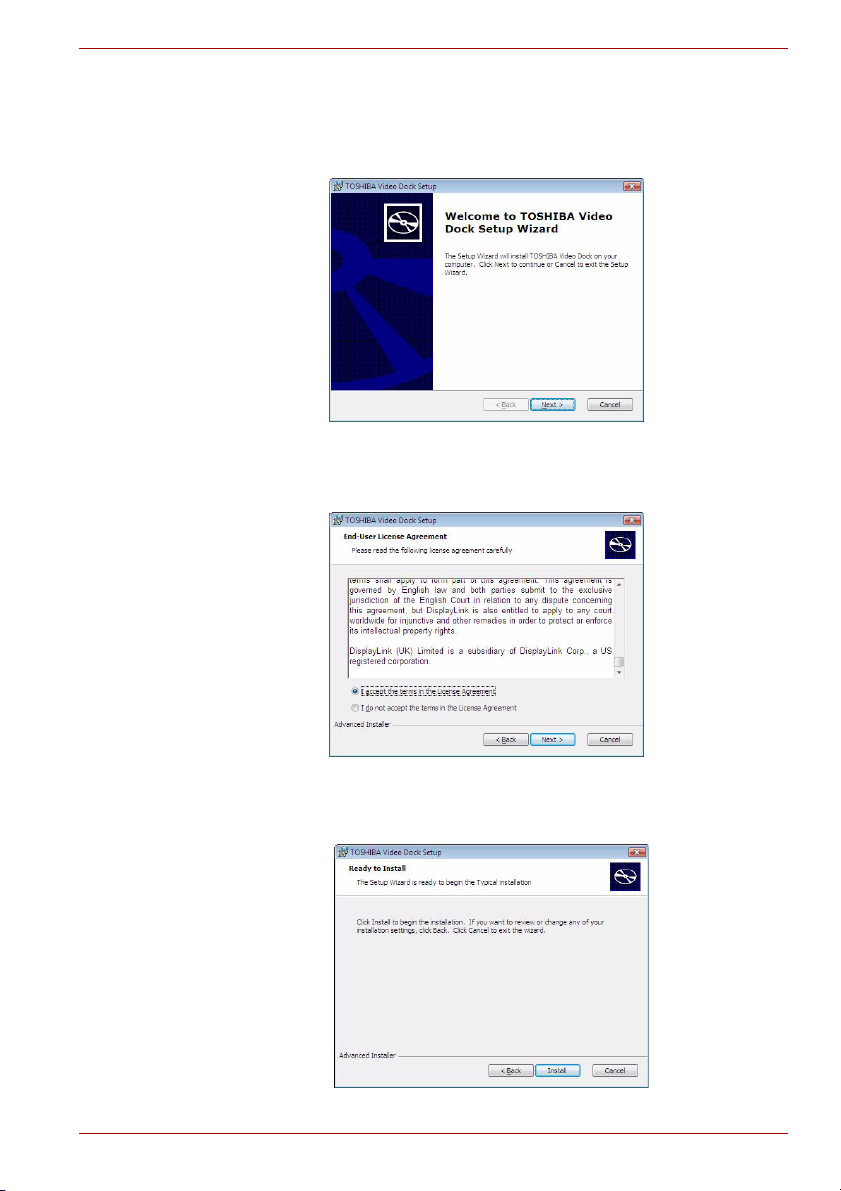
3. After the utility installation is completed, the “Video” driver will be
installed.
Step 1: When the welcome screen appears, click Next.
(Sample Image) Welcome screen
Step 2: Select “I accept the terms in the License Agreement” and click
Next.
(Sample Illustration) License Agreement screen
Step 3: Click Install to start the installation. This may take several
minutes.
(Sample Image) Ready to Install screen
User’s Manual EN-17
dynadock™
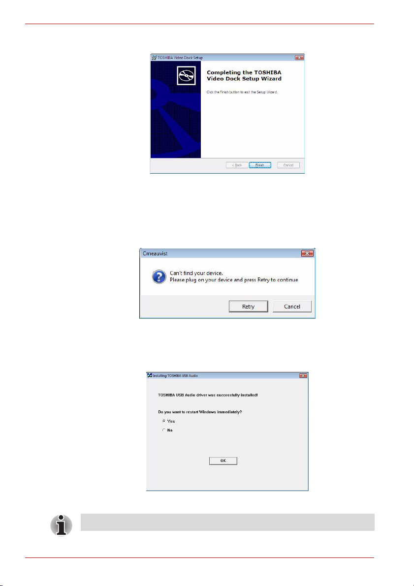
Step 4: Click Finish when the dialog box shown below appears.
(Sample Image) Finish screen
4. Once the video drivers are installed, the “Audio” driver will be installed
automatically. This step requires the dynadock to be connected to your
computer. If the dynadock is not detected, the following message will
appear. Please connect the dynadock to your computer and click Retry
to proceed.
(Sample Image) Not detected the dynadock screen
5. After finishing the installation, the program will request you to restart the
computer. Choose “Yes” and click OK to finish the setup. All devices will
take effect after restarting.
(Sample Image) Restart computer screen
NOTE: This completes the installation for Windows Vista.
EN-18 User’s Manual
Installation
Windows XP Operations:
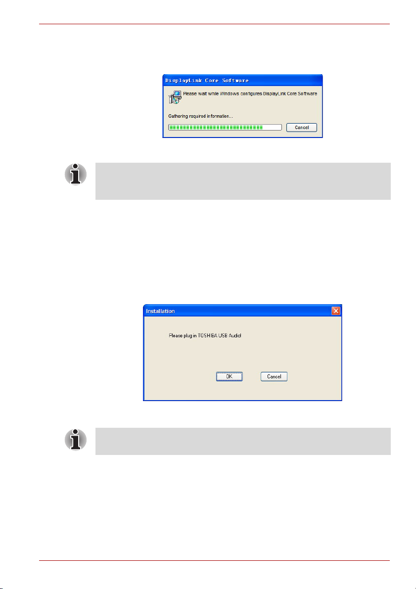
3. After the utility installation is completed, the “Video” driver will be
installed automatically.
(Sample Image) Video driver Install screen
NOTE: During the installation, the screen will flicker a couple of times. This
is normal. A dialog box may prompt to restart the computer. Please do not
restart at this time in order to install additional drivers.
4. Once the video drivers are installed, a message will prompt you to
install the “Audio” driver. This step requires the dynadock to be
connected to your computer. Click OK to proceed or connect the
dynadock to your computer now by referring to the Connecting the
dynadock to the Computer section.
If the dynadock is not detected, the message will appear again. Please
make sure the dynadock is connected correctly.
If you click Cancel, the program will exit the installation of the audio
driver.
(Sample Image) Not detected the dynadock screen
NOTE: Installation of the “Audio” driver will fail if the dynadock is not
connected to the PC.
User’s Manual EN-19
dynadock™
5. Install drivers.
Follow the screen directions to finish the driver installation.
Step 1: When the welcome screen appears, click Next.
(Sample Image) Setting selection screen
Step 2: Choose a destination location for the installation or just use the
default location. Then click Next.
(Sample Image) Choose Destination Location screen
Step 3: Click Next to start copying the program files to your computer.
This step may take a few minutes to install.
(Sample Image) Installation files copying screen
EN-20 User’s Manual
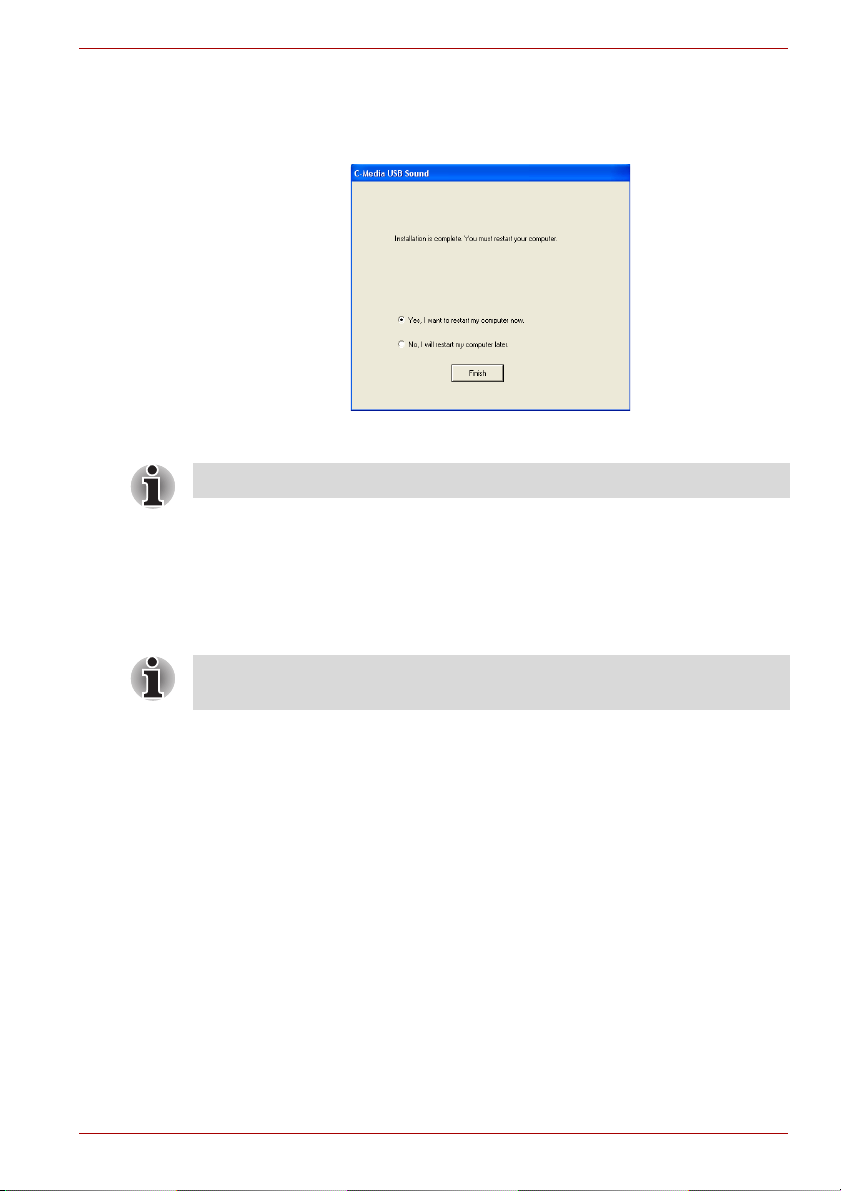
6. After finishing the installation, the program will request that you restart
the computer. Choose “Yes, I want to restart my computer now” and
click Finish to finish the setup. All devices will take effect after
restarting.
(Sample Image) Restart computer screen
NOTE: This completes the installation for Windows XP.
Background Utility Program
After the dynadock utility is installed, a program named ‘TOSHIBASvr.exe’
will run automatically in the background. It can be viewed in the Windows
Task Manager. The program can detect the insertion and removal of the
dynadock.
Installation
NOTE: The utility program does not impact any other programs on your
PC. Please do not turn it off.
User’s Manual EN-21
dynadock™
Uninstalling
To remove the dynadock Utility and all the drivers from your computer,
please follow the following procedures to remove the Utility, the Video
driver and the Audio driver one by one.
Uninstalling - Windows Vista Operations
Uninstalling the Utility
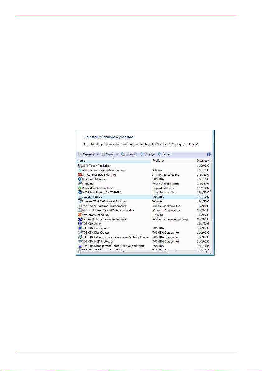
1. To remove the dynadock utility from your computer, open Uninstall a
program from the Control Panel. Choose “dynadock Utility” from the
list, and click the Uninstall button.
(Sample Illustration) Uninstall the program
2. Follow the screen directions to finish the uninstalling.
EN-22 User’s Manual
Uninstalling the Video Driver
1. To remove the Video driver completely, open Uninstall a program from
the Control Panel, then choose “TOSHIBA Video Dock” and click the
Uninstall button.
(Sample Illustration) Uninstall TOSHIBA Video Dock
2. Follow the screen directions to finish the uninstalling.
Uninstalling
User’s Manual EN-23
dynadock™
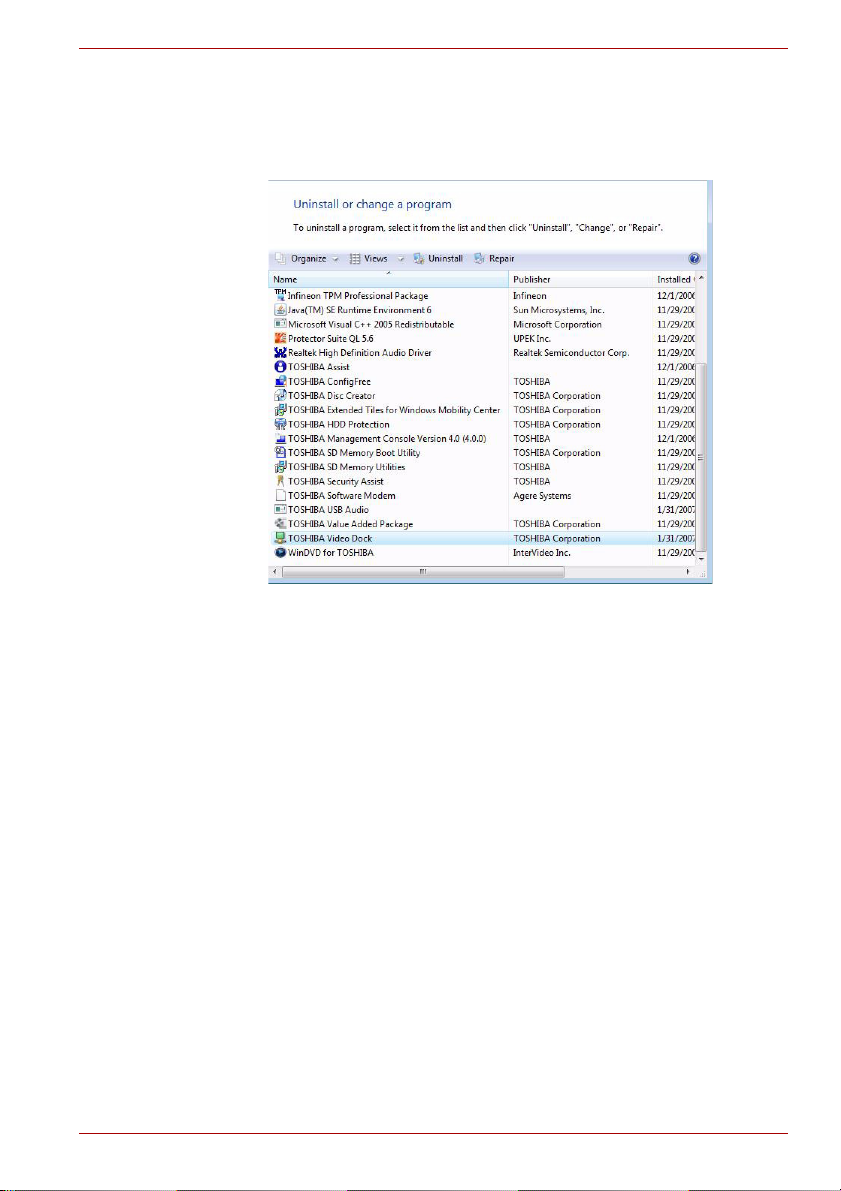
Uninstall the Audio Driver
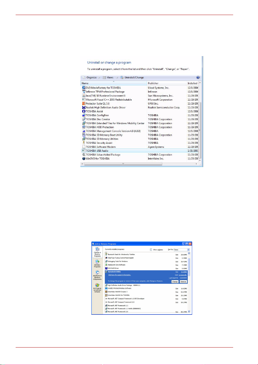
1. To remove the Audio driver completely, open Uninstall a program from
the Control Panel, then choose “TOSHIBA USB Audio” and click the
Uninstall/Change button.
2. Follow the screen directions to finish the uninstalling.
(Sample Illustration) Uninstall TOSHIBA USB Audio
Uninstalling - Windows XP Operations
Uninstalling the Utility
1. To remove the dynadock utility from your computer, open Add/Remove
Programs from the Control Panel. Choose “dynadock Utility” from the
list, and click the Remove button.
(Sample Illustration) Remove the program
2. Follow the screen directions to finish the uninstalling.
EN-24 User’s Manual
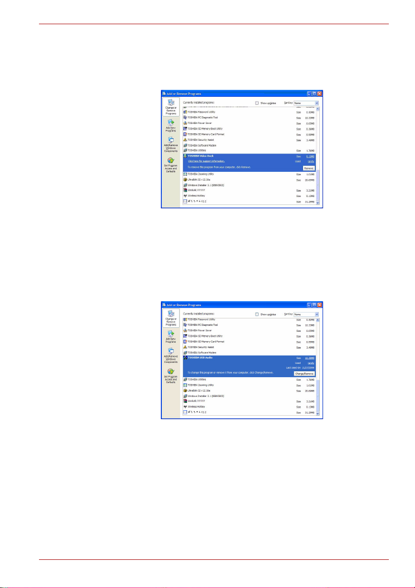
Uninstalling the Video Driver
1. To remove the Video driver completely, please open Add/Remove
Programs from the Control Panel, then choose “TOSHIBA Video
Dock” and click the Remove button.
(Sample Illustration) Remove TOSHIBA Video Dock
2. Follow the screen directions to finish the uninstalling.
Uninstall the Audio Driver
1. To remove the Audio driver completely, please open Add/Remove
Programs from the Control Panel, then choose “TOSHIBA USB
Audio” and click the Change/Remove button.
Uninstalling
(Sample Illustration) Remove TOSHIBA USB Audio
2. Follow the screen directions to finish the uninstalling.
User’s Manual EN-25

dynadock™
Using the dynadock
You may connect devices to the appropriate ports on the dynadock while
your computer is running. A slight delay and display flickering is normal
before the computer recognizes the new device. Please be patient.
USB 2.0 Ports (Front and Back Panel)
Connect any USB device to one of the dynadock’s six USB ports.
■ When no device is connected to the port, the indicator light is off.
■ If a device is connected to the port and the connection works properly,
the indicator light glows green (on).
■ If your USB device, such as a printer or optical drive, etc., came with its
own AC adaptor, make sure that it is plugged into the device and a live
electrical outlet.
NOTE: Only the front two USB ports provide power when the computer is
either off, suspended or disconnected.
Ethernet Port (Back Panel)
Connect one end of a network cable (not provided) to the Ethernet port (RJ-
45) on the dynadock and the other end to your network for high
performance network access. To configure the network properties of the
Ethernet adapter:
In Windows Vista, select Start > Control Panel > View network status
and tasks > Manage network connections.
In Windows XP, select Start > Settings > Network Connections.
In the Network Connections folder, double-click the connection icon for
the dynadock’s Ethernet adapter, which is indicated by ASIX AX88772
USB2.0 to Fast Ethernet Adapter.
(Sample Image) Network Connection icon
EN-26 User’s Manual
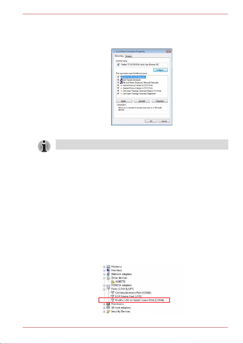
This will open the Local Area Connection Properties window for you to
configure the network settings as required according to your network
environment. If you are unsure about the settings, consult your network
administrator for assistance.
(Sample Image) Local Area Connection Properties
NOTE: The LAN port does not support Wake-On-LAN.
Serial Port (Back Panel)
Using the dynadock
To connect a serial device, attach the serial cable (not provided) to the
serial port on the dynadock and your serial device. Then install the software
driver according to the instructions that come with the device. When
prompted to select the port, choose COMx, where x is the COM port
number assigned by your operating system.
To see the COM port number assigned by your operating system:
1. In Windows Vista, please open Manage by right-clicking Computer and
select Device Manager.
In Windows XP, please open Device Manager by right-clicking My
Computer and select Properties. Then click Hardware > Device
Manager.
2. Under the Ports (COM & LPT) group, you should be able to find
Prolific USB-to-Serial Comm Port. The com port number will appear
next to the string.
(Sample Image) Locating the Serial Comm Port
User’s Manual EN-27
dynadock™
Windows Vista Windows XP
Front Panel Audio Port (Microphone)
To connect a microphone, plug the 3.5 mm mono microphone jack into the
microphone input port.
Front Panel Audio Port (Headphones or Speakers)
After installing the provided audio software, a USB 3D 106 Sound
Configuration utility is installed in your computer. It can be accessed by
double-clicking the USB 3D 106 Sound Configuration icon on the system
tray.
(Sample Image) USB 3D 106 Sound Configuration
NOTE: If the audio software has been properly installed and the icon is not
on the system tray, it means the dynadock is connected to a different USB
port from the one originally connected for installation. Re-plug the
dynadock into the original USB port and the icon will appear again.
The utility comes with a friendly graphic user interface to optimize your
audio effects. Most of the settings can be adjusted using the available
sliders, images or buttons. Just make the adjustments to suit your personal
preferences.
Using Virtual 7.1CH Function on 2CH Speakers/headphones
The audio output port on the front panel is used to connect stereo speakers
or headphones. Although 2CH speakers may be connected, a virtual 7.1CH
surround sound experience is possible using the software’s virtual multichannel function.
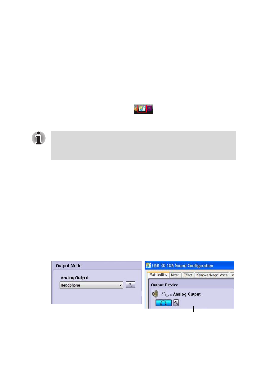
To enable the virtual 7.1CH audio function on 2CH speakers or
headphones:
1. In the Analog Output section, select headphone (or the headphone
icon in Windows XP).
(Sample Image) Select headphone
EN-28 User’s Manual
Using the dynadock
Windows Vista Windows XP
Windows Vista Windows XP
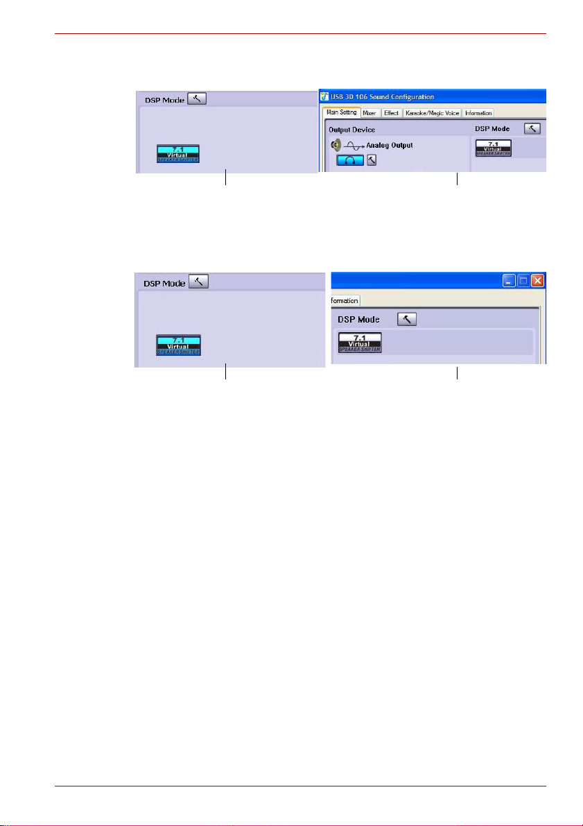
2. On the panel, click the 7.1 Virtual SPEAKER SHIFTER button to
enable the virtual multi-channel function.
(Sample Image) 7.1 Virtual SPEAKER SHIFTER button
3. The button next to DSP Mode string allows you to switch between the
SHIFTER control and basic control window.
(Sample Image) DSP button
Launch the USB 3D 106 Sound Configuration utility from the System
Tray. Click on the Virtual Speaker Shifter button to open the Shifter
controls.
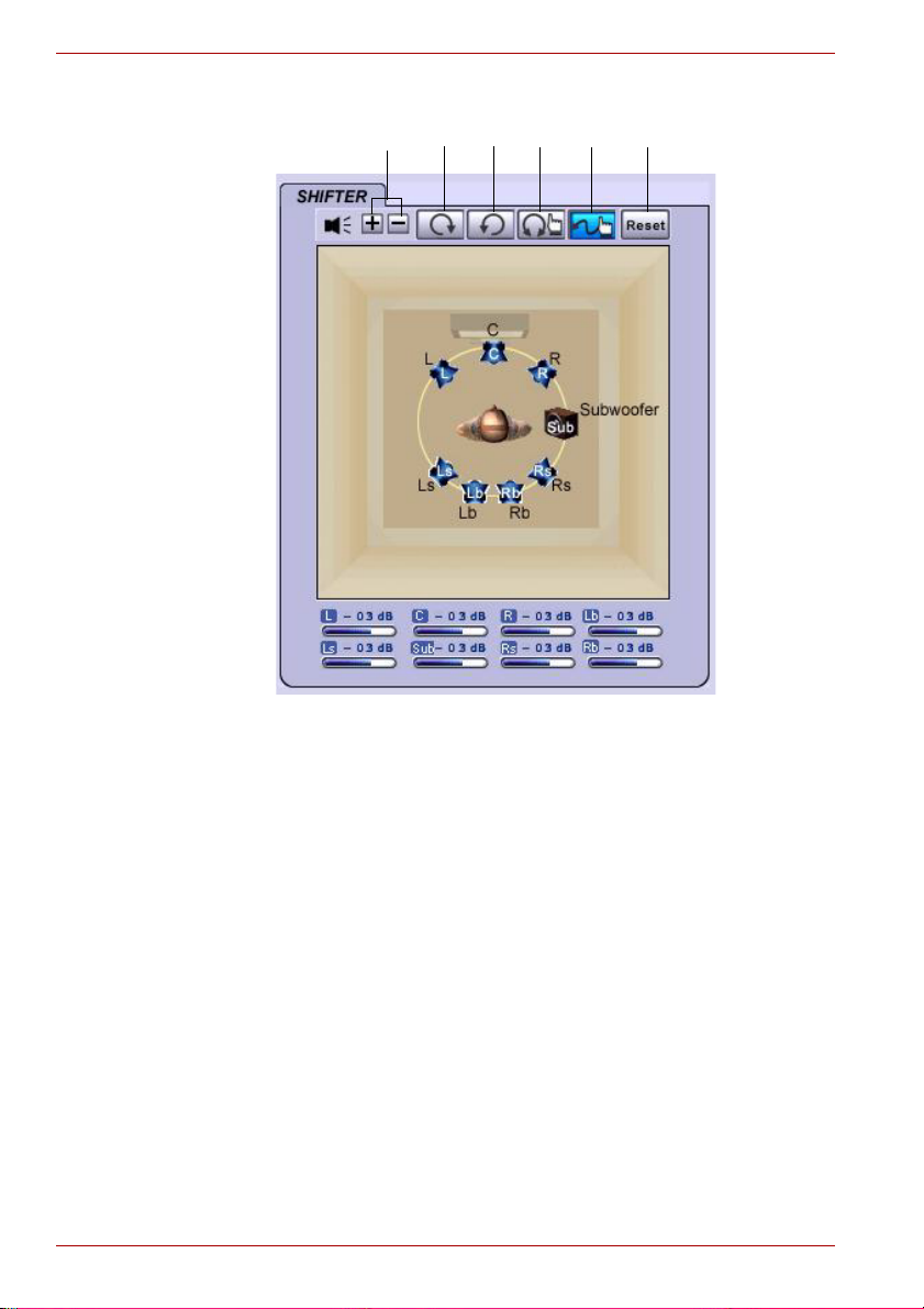
Using the Virtual Speaker Shifter Controls
1. Volume control
2. Rotate all the virtual speakers clockwise
3. Rotate all the virtual speakers counterclockwise
4. Manually rotate all the virtual speakers
5. Manual shifting function. You can drag a specific virtual speaker to the
preferred position to enhance an individual channel output. For
example, a low-volume center (for dialog) can be enhanced by being
dragged closer to you
User’s Manual EN-29
dynadock™
2
1
3
4
5
6
6. Reset the speakers to default settings
(Sample Image) Shifter Controls
Using the Basic Controls
1. To adjust/reset the volume of the left and right channel of your
speakers/headphones
2. To test the left and right channel of your speakers/headphones
EN-30 User’s Manual
 Loading...