

Page 1

NB300 series User's Manual
TOSHIBA
NB300 series
User's Manual
Page 2

Copyright
Disclaimer
© 2009 by TOSHIBA Corporation. All rights reserved. Under the copyright
laws, this manual cannot be reproduced in any form without the prior
written permission of TOSHIBA. No patent liability is assumed, with respect
to the use of the information contained herein.
TOSHIBA NB300 series User’s Manual
First edition October 2009
Copyright authority for music, movies, computer programs, databases and
other intellectual property covered by copyright laws belongs to the author
or to the copyright owner. Copyrighted material can be reproduced only for
personal use or use within the home. Any other use beyond that stipulated
above (including conversion to digital format, alteration, transfer of copied
material and distribution on a network) without the permission of the
copyright owner is a violation of copyright or author's rights and is subject to
civil damages or criminal action. Please comply with copyright laws in
making any reproduction from this manual.
This manual has been validated and reviewed for accuracy. The
instructions and descriptions it contains are accurate for the TOSHIBA
NB300 Portable Personal Computers at the time of this manual’s
production. However, succeeding computers and manuals are subject to
change without notice. TOSHIBA assumes no liability for damages incurred
directly or indirectly from errors, omissions or discrepancies between the
computer and the manual.
Trademarks
IBM is a registered trademark and IBM PC is a trademark of International
Business Machine Corporation.
Intel, Intel Atom are registered trademarks or trademarks of Intel
Corporation.
Microsoft, Windows and Windows logo are either registered trademarks or
trademarks of Microsoft Corporation.
DirectX, ActiveDesktop, DirectShow, and Windows Media are registered
trademarks of Microsoft Corporation.
Adobe is either a registered trademark or trademark of Adobe Systems
Incorporated in the United States.
Bluetooth is a registered trademark owned by its proprietor and used by
TOSHIBA under license.
ConfigFree is a trademark of TOSHIBA Corporation,
Wi-Fi is a registered trademark of the Wi-Fi Alliance.
Secure Digital and SD are trademarks of the SD Card Association.
User’s Manual ii
Page 3

MultiMediaCard and MMC are trademarks of the MultiMediaCard
Association.
Other trademarks and registered trademarks not listed above may be used
in this manual.
FCC information
FCC notice "Declaration of Conformity Information"
This equipment has been tested and found to comply with the limits for a
Class B digital device, pursuant to part 15 of the FCC rules. These limits
are designed to provide reasonable protection against harmful interference
in a residential installation. This equipment generates, uses and can radiate
radio frequency energy and, if not installed and used in accordance with the
instructions, may cause harmful interference to radio communications.
However, there is no guarantee that interference will not occur in a
particular installation. If this equipment does cause harmful interference to
radio or television reception, which can be determined by turning the
equipment off and on, the user is encouraged to try to correct the
interference by one or more of the following measures:
■ Reorient or relocate the receiving antenna.
■ Increase the separation between the equipment and receiver.
■ Connect the equipment into an outlet on a circuit different from that to
which the receiver is connected.
■ Consult the dealer or an experienced radio/TV technician for help.
Only peripherals complying with the FCC class B limits may be attached to
this equipment. Operation with non-compliant peripherals or peripherals
not recommended by TOSHIBA is likely to result in interference to radio
and TV reception. Shielded cables must be used between the external
devices and the computer’s external monitor port, Universal Serial Bus
(USB 2.0) ports and microphone jack. Changes or modifications made to
this equipment, not expressly approved by TOSHIBA or parties authorized
by TOSHIBA could void the user’s authority to operate the equipment.
FCC conditions
This device complies with part 15 of the FCC Rules. Operation is subject to
the following two conditions:
1. This device may not cause harmful interference.
2. This device must accept any interference received, including
interference that may cause undesired operation.
User’s Manual iii
Page 4
Contact
Address: TOSHIBA America Information Systems, Inc.
9740 Irvine Boulevard
Irvine, California 92618-1697
Telephone: (949) 583-3000
EU Conformity Statement
This product and - if applicable - the supplied accessories too are marked
with "CE" and comply therefore with the applicable harmonized European
standards listed under the Low Voltage Directive 2006/95/EC, the EMC
Directive 2004/108/EC and/or R&TTE Directive 1999/5/EC
Responsible for CEmarking:
Manufacturer: Toshiba Corporation, 1-1 Shibaura 1-chome,
The complete official EU CE Declaration can be obtained on following
internet page:
http://epps.toshiba-teg.com/
Regulatory and agency labels may be located on the computer bottom or under
battery.
VCCI Class B Information
TOSHIBA EUROPE GMBH, Hammfelddamm 8,
41460 Neuss, Germany
Minato-ku, Tokyo, 105-8001, Japan
User’s Manual iv
Page 5

Canadian regulatory information (Canada only)
This digital apparatus does not exceed the Class B limits for radio noise
emissions from digital apparatus as set out in the Radio Interference
Regulation of the Canadian Department of Communications.
Note that Canadian Department of Communications (DOC) regulations
provide, that changes or modifications not expressly approved by
TOSHIBA Corporation could void your authority to operate this equipment.
This Class B digital apparatus meets all requirements of the Canadian
Interference Causing Equipment Regulations.
Cet appareil numérique de la class B respecte toutes les exgences du
Règlement sur le matériel brouileur du Canada.
Following information is only for EU-member states:
Disposal of products
The crossed out wheeled dust bin symbol indicates that products must be
collected and disposed of separately from household waste. Integrated
batteries and accumulators can be disposed of with the product. They will
be separated at the recycling centres.
The black bar indicates that the product was placed on the market after
August 13, 2005.
By participating in separate collection of products and batteries, you will
help to assure the proper disposal of products and batteries and thus help
to prevent potential negative consequences for the environment and human
health.
For more detailed information about the collection and recycling
programmes available in your country, please visit our website
(http://eu.computers.toshiba-europe.com) or contact your local city office or
the shop where you purchased the product.
User’s Manual v
Page 6

Disposal of batteries and/or accumulators
The crossed out wheeled dust bin symbol indicates that batteries and/or
accumulators must be collected and disposed of separately from household
waste.
If the battery or accumulator contains more than the specified values of lead
3E+J&G
(Pb), mercury (Hg), and/or cadmium (Cd) defined in the Battery Directive
(2006/66/EC), then the chemical symbols for lead (Pb), mercury (Hg) and/or
cadmium (Cd) will appear below the crossed out wheeled dust bin symbol.
By participating in separate collection of batteries, you will help to assure
the proper disposal of products and batteries and thus help to prevent
potential negative consequences for the environment and human health.
For more detailed information about the collection and recycling
programmes available in your country, please visit our website
(http://eu.computers.toshiba-europe.com) or contact your local city office or
the shop where you purchased the product.
This symbol may not be displayed depending on the country and region
where you purchased.
ENERGY STAR® Program
Your Computer model may be ENERGY STAR
®
compliant. If the model you
purchased is compliant, it is labeled with the ENERGY STAR logo on the
computer and the following information applies.
TOSHIBA is a partner in the ENERGY STAR Program and has designed
this computer to meet the latest ENERGY STAR guidelines for energy
efficiency. Your computer ships with the power management options preset
to a configuration that will provide the most stable operating environment
and optimum system performance for both AC power and battery modes.
To conserve energy, your computer is set to enter the low-power Sleep
mode which shuts down the system and display within 15 minutes of
inactivity in AC power mode. TOSHIBA recommends that you leave this
and other energy saving features active, so that your computer will operate
at its maximum energy efficiency. You can wake the computer from Sleep
mode by pressing the power button.
Products that earn the ENERGY STAR prevent greenhouse gas emissions
by meeting strict energy efficiency guidelines set by the US EPA and the EU
Commission. According to the EPA, a computer meeting the new ENERGY
STAR specifications will use between 20% and 50% less energy depending
on how it is used.
Visit http://www.eu-energystar.org or http://www.energystar.gov for more
information regarding the ENERGY STAR Program.
User’s Manual vi
Page 7

Disposing of the computer and the computer’s batteries
■ Discard this computer in accordance with applicable laws and
regulations. For further information, contact your local government.
■ This computer contains rechargeable batteries. After repeated use, the
batteries will finally lose their ability to hold a charge and you will need
to replace them. Under certain applicable laws and regulation, it may be
illegal to dispose of old batteries by placing them in the trash.
■ Please be kind to our shared environment. Check with your local
government authority for details regarding where to recycle old batteries
or how to dispose of them properly. This product contains mercury.
Disposal of this material may be regulated due to environmental
considerations. For disposal, reuse or recycling information, please
contact your local government.
User’s Manual vii
Page 8

Table of Contents
Copyright. . . . . . . . . . . . . . . . . . . . . . . . . . . . . . . . . . . . . . . . . . . . . . . . . . ii
Disclaimer . . . . . . . . . . . . . . . . . . . . . . . . . . . . . . . . . . . . . . . . . . . . . . . . . ii
Trademarks . . . . . . . . . . . . . . . . . . . . . . . . . . . . . . . . . . . . . . . . . . . . . . . . ii
FCC information . . . . . . . . . . . . . . . . . . . . . . . . . . . . . . . . . . . . . . . . . . . iii
EU Conformity Statement . . . . . . . . . . . . . . . . . . . . . . . . . . . . . . . . . . . iv
VCCI Class B Information . . . . . . . . . . . . . . . . . . . . . . . . . . . . . . . . . . . iv
Canadian regulatory information (Canada only) . . . . . . . . . . . . . . . . . . v
Following information is only for EU-member states: . . . . . . . . . . . . . v
ENERGY STAR® Program . . . . . . . . . . . . . . . . . . . . . . . . . . . . . . . . . . . vi
Preface
Manual contents . . . . . . . . . . . . . . . . . . . . . . . . . . . . . . . . . . . . . . . . . . . xii
Conventions . . . . . . . . . . . . . . . . . . . . . . . . . . . . . . . . . . . . . . . . . . . . . xiii
General Precautions
Provide adequate ventilation. . . . . . . . . . . . . . . . . . . . . . . . . . . . . . . . . xv
Creating a computer-friendly environment . . . . . . . . . . . . . . . . . . . . xvi
Stress injury . . . . . . . . . . . . . . . . . . . . . . . . . . . . . . . . . . . . . . . . . . . . . xvi
Heat injury . . . . . . . . . . . . . . . . . . . . . . . . . . . . . . . . . . . . . . . . . . . . . . . xvi
Pressure or impact damage. . . . . . . . . . . . . . . . . . . . . . . . . . . . . . . . . xvii
Mobile phones . . . . . . . . . . . . . . . . . . . . . . . . . . . . . . . . . . . . . . . . . . . xvii
Instruction Manual for Safety and Comfort . . . . . . . . . . . . . . . . . . . . xvii
Chapter 1 Introduction
Equipment checklist. . . . . . . . . . . . . . . . . . . . . . . . . . . . . . . . . . . . . . . 1-1
Features. . . . . . . . . . . . . . . . . . . . . . . . . . . . . . . . . . . . . . . . . . . . . . . . . 1-3
Special features . . . . . . . . . . . . . . . . . . . . . . . . . . . . . . . . . . . . . . . . . . 1-8
TOSHIBA Value Added Package . . . . . . . . . . . . . . . . . . . . . . . . . . . . 1-11
Utilities and Applications. . . . . . . . . . . . . . . . . . . . . . . . . . . . . . . . . . 1-12
Options . . . . . . . . . . . . . . . . . . . . . . . . . . . . . . . . . . . . . . . . . . . . . . . . 1-13
Chapter 2 The Grand Tour
Front with the display closed . . . . . . . . . . . . . . . . . . . . . . . . . . . . . . . 2-1
System indicators. . . . . . . . . . . . . . . . . . . . . . . . . . . . . . . . . . . . . . . . . 2-1
Left side. . . . . . . . . . . . . . . . . . . . . . . . . . . . . . . . . . . . . . . . . . . . . . . . . 2-3
User’s Manual viii
Page 9

Right side . . . . . . . . . . . . . . . . . . . . . . . . . . . . . . . . . . . . . . . . . . . . . . . 2-5
Back side. . . . . . . . . . . . . . . . . . . . . . . . . . . . . . . . . . . . . . . . . . . . . . . . 2-6
Underside . . . . . . . . . . . . . . . . . . . . . . . . . . . . . . . . . . . . . . . . . . . . . . . 2-6
Front with the display open. . . . . . . . . . . . . . . . . . . . . . . . . . . . . . . . . 2-8
AC adaptor . . . . . . . . . . . . . . . . . . . . . . . . . . . . . . . . . . . . . . . . . . . . . 2-11
Chapter 3 Getting Started
Connecting the AC adaptor . . . . . . . . . . . . . . . . . . . . . . . . . . . . . . . . . 3-3
Opening the display . . . . . . . . . . . . . . . . . . . . . . . . . . . . . . . . . . . . . . . 3-5
Turning on the power . . . . . . . . . . . . . . . . . . . . . . . . . . . . . . . . . . . . . . 3-7
Starting up for the first time . . . . . . . . . . . . . . . . . . . . . . . . . . . . . . . . 3-7
Turning off the power. . . . . . . . . . . . . . . . . . . . . . . . . . . . . . . . . . . . . . 3-8
Restarting the computer . . . . . . . . . . . . . . . . . . . . . . . . . . . . . . . . . . 3-11
System Recovery Options . . . . . . . . . . . . . . . . . . . . . . . . . . . . . . . . . 3-11
Chapter 4 Operating Basics
Using the Touch Pad . . . . . . . . . . . . . . . . . . . . . . . . . . . . . . . . . . . . . . 4-1
USB Sleep and Charge function . . . . . . . . . . . . . . . . . . . . . . . . . . . . . 4-2
TOSHIBA Disc Creator . . . . . . . . . . . . . . . . . . . . . . . . . . . . . . . . . . . . . 4-4
Using the web camera . . . . . . . . . . . . . . . . . . . . . . . . . . . . . . . . . . . . . 4-6
Using TOSHIBA Web Camera Application . . . . . . . . . . . . . . . . . . . . . 4-7
Using the microphone . . . . . . . . . . . . . . . . . . . . . . . . . . . . . . . . . . . . . 4-8
Wireless communications . . . . . . . . . . . . . . . . . . . . . . . . . . . . . . . . . . 4-8
LAN . . . . . . . . . . . . . . . . . . . . . . . . . . . . . . . . . . . . . . . . . . . . . . . . . . . 4-11
Cleaning the computer. . . . . . . . . . . . . . . . . . . . . . . . . . . . . . . . . . . . 4-12
Moving the computer . . . . . . . . . . . . . . . . . . . . . . . . . . . . . . . . . . . . . 4-13
Heat dispersal . . . . . . . . . . . . . . . . . . . . . . . . . . . . . . . . . . . . . . . . . . . 4-14
Using the Hard Disk Drive (HDD) Protection . . . . . . . . . . . . . . . . . . 4-14
Chapter 5 The Keyboard
Typewriter keys. . . . . . . . . . . . . . . . . . . . . . . . . . . . . . . . . . . . . . . . . . . 5-1
Function keys: F1 … F12 . . . . . . . . . . . . . . . . . . . . . . . . . . . . . . . . . . 5-2
Soft keys: FN key combinations . . . . . . . . . . . . . . . . . . . . . . . . . . . . . 5-2
Hot keys. . . . . . . . . . . . . . . . . . . . . . . . . . . . . . . . . . . . . . . . . . . . . . . . . 5-3
Windows special keys . . . . . . . . . . . . . . . . . . . . . . . . . . . . . . . . . . . . . 5-6
Keypad overlay . . . . . . . . . . . . . . . . . . . . . . . . . . . . . . . . . . . . . . . . . . . 5-6
Generating ASCII characters. . . . . . . . . . . . . . . . . . . . . . . . . . . . . . . . 5-8
Chapter 6 Power and Power-up Modes
Power conditions . . . . . . . . . . . . . . . . . . . . . . . . . . . . . . . . . . . . . . . . . 6-1
Power indicators. . . . . . . . . . . . . . . . . . . . . . . . . . . . . . . . . . . . . . . . . . 6-2
Battery types. . . . . . . . . . . . . . . . . . . . . . . . . . . . . . . . . . . . . . . . . . . . . 6-3
Care and use of the battery pack . . . . . . . . . . . . . . . . . . . . . . . . . . . . 6-5
Replacing the battery pack . . . . . . . . . . . . . . . . . . . . . . . . . . . . . . . . . 6-9
TOSHIBA Password Utility. . . . . . . . . . . . . . . . . . . . . . . . . . . . . . . . . 6-12
Power-up modes. . . . . . . . . . . . . . . . . . . . . . . . . . . . . . . . . . . . . . . . . 6-13
User’s Manual ix
Page 10

Chapter 7 HW Setup and Passwords
HW Setup. . . . . . . . . . . . . . . . . . . . . . . . . . . . . . . . . . . . . . . . . . . . . . . . 7-1
Accessing HW Setup . . . . . . . . . . . . . . . . . . . . . . . . . . . . . . . . . . . . . . 7-1
HW Setup Window . . . . . . . . . . . . . . . . . . . . . . . . . . . . . . . . . . . . . . . . 7-1
Chapter 8 Optional Devices
Bridge media slot . . . . . . . . . . . . . . . . . . . . . . . . . . . . . . . . . . . . . . . . . 8-2
Additional memory module . . . . . . . . . . . . . . . . . . . . . . . . . . . . . . . . . 8-4
Battery Packs . . . . . . . . . . . . . . . . . . . . . . . . . . . . . . . . . . . . . . . . . . . . 8-7
Universal AC Adaptor . . . . . . . . . . . . . . . . . . . . . . . . . . . . . . . . . . . . . 8-7
USB floppy diskette drive . . . . . . . . . . . . . . . . . . . . . . . . . . . . . . . . . . 8-7
USB optical disc drive . . . . . . . . . . . . . . . . . . . . . . . . . . . . . . . . . . . . . 8-7
External monitor . . . . . . . . . . . . . . . . . . . . . . . . . . . . . . . . . . . . . . . . . . 8-8
Security lock . . . . . . . . . . . . . . . . . . . . . . . . . . . . . . . . . . . . . . . . . . . . . 8-8
Chapter 9 Troubleshooting
Problem solving process. . . . . . . . . . . . . . . . . . . . . . . . . . . . . . . . . . . 9-1
Hardware and system checklist . . . . . . . . . . . . . . . . . . . . . . . . . . . . . 9-3
TOSHIBA support . . . . . . . . . . . . . . . . . . . . . . . . . . . . . . . . . . . . . . . . 9-14
Chapter 10 Legal Footnotes
CPU*1. . . . . . . . . . . . . . . . . . . . . . . . . . . . . . . . . . . . . . . . . . . . . . . . . . 10-1
Memory (Main System)*2 . . . . . . . . . . . . . . . . . . . . . . . . . . . . . . . . . . 10-2
Battery Life*3 . . . . . . . . . . . . . . . . . . . . . . . . . . . . . . . . . . . . . . . . . . . 10-2
HDD drive capacity*4 . . . . . . . . . . . . . . . . . . . . . . . . . . . . . . . . . . . . . 10-2
LCD . . . . . . . . . . . . . . . . . . . . . . . . . . . . . . . . . . . . . . . . . . . . . . . . . . . 10-3
Graphics Processor Unit (GPU) . . . . . . . . . . . . . . . . . . . . . . . . . . . . 10-3
Wireless LAN*7 . . . . . . . . . . . . . . . . . . . . . . . . . . . . . . . . . . . . . . . . . . 10-3
Non-applicable Icons . . . . . . . . . . . . . . . . . . . . . . . . . . . . . . . . . . . . . 10-3
Copy Protection . . . . . . . . . . . . . . . . . . . . . . . . . . . . . . . . . . . . . . . . . 10-3
USB Sleep and Charge. . . . . . . . . . . . . . . . . . . . . . . . . . . . . . . . . . . . 10-3
Appendix A Specifications
Physical Dimensions . . . . . . . . . . . . . . . . . . . . . . . . . . . . . . . . . . . . . . A-1
Environmental requirements . . . . . . . . . . . . . . . . . . . . . . . . . . . . . . . . A-1
Appendix B Display Controller
Display controller . . . . . . . . . . . . . . . . . . . . . . . . . . . . . . . . . . . . . . . . . B-1
Appendix C Wireless LAN
Card Specifications . . . . . . . . . . . . . . . . . . . . . . . . . . . . . . . . . . . . . . . C-1
Radio Characteristics. . . . . . . . . . . . . . . . . . . . . . . . . . . . . . . . . . . . . . C-1
Supported frequency sub-bands . . . . . . . . . . . . . . . . . . . . . . . . . . . . C-2
Appendix D AC Power Cord and Connectors
Certification agencies . . . . . . . . . . . . . . . . . . . . . . . . . . . . . . . . . . . . . D-2
User’s Manual x
Page 11

Appendix E TOSHIBA PC Health Monitor
Starting the TOSHIBA PC Health Monitor. . . . . . . . . . . . . . . . . . . . . . E-2
If a TOSHIBA PC Health Monitor message is displayed . . . . . . . . . . E-2
Glossary
Index
User’s Manual xi
Page 12

Preface
Congratulations on your purchase of the TOSHIBA NB300 computer. This
powerful notebook computer provides excellent expansion capability,
includes multimedia functionality, and is designed to provide years of
reliable, high-performance computing.
This manual tells how to set up and begin using your TOSHIBA NB300
computer. It also provides detailed information on configuring your
computer, basic operations and care, using optional devices and
troubleshooting.
If you are a new user of computers or if you’re new to portable computing,
first read over the Introduction and The Grand Tour chapters to familiarize
yourself with the computer’s features, components and accessory devices.
Then read Getting Started for step-by-step instructions on setting up your
computer.
If you are an experienced computer user, please continue reading the
preface to learn how this manual is organized, then become acquainted
with this manual by browsing through its pages. Be sure to read the Special
features section of the Introduction, to learn about features that are
uncommon or unique to this computer and carefully read HW Setup and
Passwords, If you are going to connect external devices such as a printer,
be sure to read Chapter 8, Optional Devices.
Manual contents
This manual is composed of the following chapters, appendixes, a glossary
and an index.
Chapter 1, Introduction, is an overview of the computer’s features,
capabilities, and options.
Chapter 2, The Grand Tour, identifies the components of the computer and
briefly explains how they function.
Chapter 3, Getting Started, provides a quick overview of how to begin
operating your computer.
Chapter 4, Operating Basics, includes tips on care of the computer and on
using the Touch Pad, the web camera, the microphone, wireless
communication and LAN.
User’s Manual xii
Page 13

Chapter 5, The Keyboard, describes special keyboard functions including
the keypad overlay and hot keys.
Chapter 6, Power and Power-up Modes, gives details on the computer’s
power resources and battery save modes.
Chapter 7, HW Setup and Passwords, explains how to configure the
computer using the HW Setup program. It also tells how to set a password.
Chapter 8, Optional Devices, describes the optional hardware available.
Chapter 9, Troubleshooting, provides helpful information on how to perform
some diagnostic tests, and suggests courses of action if the computer
doesn’t seem to be working properly.
Chapter 10, Legal Footnotes, provides Legal Footnotes information related
to your computer.
The Appendixes provide technical information about your computer.
The Glossary defines general computer terminology and includes a list of
acronyms used in the text.
The Index quickly directs you to the information contained in this manual.
Conventions
This manual uses the following formats to describe, identify, and highlight
terms and operating procedures.
Abbreviations
On first appearance, and whenever necessary for clarity, abbreviations are
enclosed in parentheses following their definition. For example: Read Only
Memory (ROM). Acronyms are also defined in the Glossary.
Preface
Icons
Icons identify ports, dials, and other parts of your computer. The indicator
panel also uses icons to identify the components it is providing information
on.
Keys
The keyboard keys are used in the text to describe many computer
operations. A distinctive typeface identifies the key top symbols as they
appear on the keyboard. For example, ENTER identifies the ENTER key.
Key operation
Some operations require you to simultaneously use two or more keys. We
identify such operations by the key top symbols separated by a plus sign
(+). For example, CTRL + C means you must hold down CTRL and at the
same time press C. If three keys are used, hold down the first two and at
the same time press the third.
User’s Manual xiii
Page 14
Preface
ABC
When procedures require an action such as
clicking an icon or entering text, the icon's name
or the text you are to type in is represented in the
typeface you see to the left.
Display
ABC
Names of windows or icons or text generated by
the computer that appear on its display screen
are presented in the type face you see to the left.
Messages
Messages are used in this manual to bring important information to your
attention. Each type of message is identified as shown below.
Pay attention! A caution informs you that improper use of equipment or
failure to follow instructions may cause data loss or damage your
equipment.
Please read. A note is a hint or advice that helps you make best use of
your equipment.
Indicates a potentially hazardous situation, which could result in death or
serious injury, if you do not follow instructions.
Terminology
This term is defined in this document as follows:
Start
User’s Manual xiv
The word "Start" refers to the " " button in
®
Windows
7.
Page 15

General Precautions
TOSHIBA computers are designed to optimize safety, minimize strain and
withstand the rigors of portability. However, certain precautions should be
observed to further reduce the risk of personal injury or damage to the
computer.
Be certain to read the general precautions below and to note the cautions
included in the text of the manual.
Provide adequate ventilation
Always make sure your computer and AC adaptor have adequate
ventilation and are protected from overheating when the power is turned on
or when an AC adaptor is connected to a power outlet (even if your
computer is in Sleep Mode). In this condition, observe the following:
■ Never cover your computer or AC adaptor with any object.
■ Never place your computer or AC adaptor near a heat source, such as
an electric blanket or heater.
■ Never cover or block the air vents including those located at the base of
the computer.
■ Always operate your computer on a hard flat surface. Using your
computer on a carpet or other soft material can block the vents.
■ Always provide sufficient space around the computer.
■ Overheating your computer or AC adaptor could cause system failure,
computer or AC adaptor damage or a fire, possibly resulting in serious
injury.
User’s Manual xv
Page 16

Creating a computer-friendly environment
Place the computer on a flat surface that is large enough for the computer
and any other items you are using, such as a printer.
Leave enough space around the computer and other equipment to provide
adequate ventilation. Otherwise, they may overheat.
To keep your computer in prime operating condition, protect your work area
from:
■ Dust, moisture, and direct sunlight.
■ Equipment that generates a strong electromagnetic field, such as
stereo speakers (other than speakers that are connected to the
computer) or speakerphones.
■ Rapid changes in temperature or humidity and sources of temperature
change such as air conditioner vents or heaters.
■ Extreme heat, cold, or humidity.
■ Liquids and corrosive chemicals.
Stress injury
Carefully read the Instruction Manual for Safety and Comfort. It contains
information on the prevention of stress injuries to your hands and wrists
that can be caused by extensive keyboard use.
General Precautions
Heat injury
■ Avoid prolonged physical contact with the computer. If the computer is
used for long periods, its surface can become very warm. While the
temperature will not feel hot to the touch, if you maintain physical
contact with the computer for a long time, for example if you rest the
computer on your lap or if you keep your hands on the palm rest, your
skin might suffer a low-heat injury.
■ If the computer has been used for a long time, avoid direct contact with
the metal plate supporting the various interface ports as this can
become hot.
■ The surface of the AC adaptor can become hot when in use but this
condition does not indicate a malfunction. If you need to transport the
AC adaptor, you should disconnect it and let it cool before moving it.
■ Do not lay the AC adaptor on a material that is sensitive to heat as the
material could become damaged.
User’s Manual xvi
Page 17

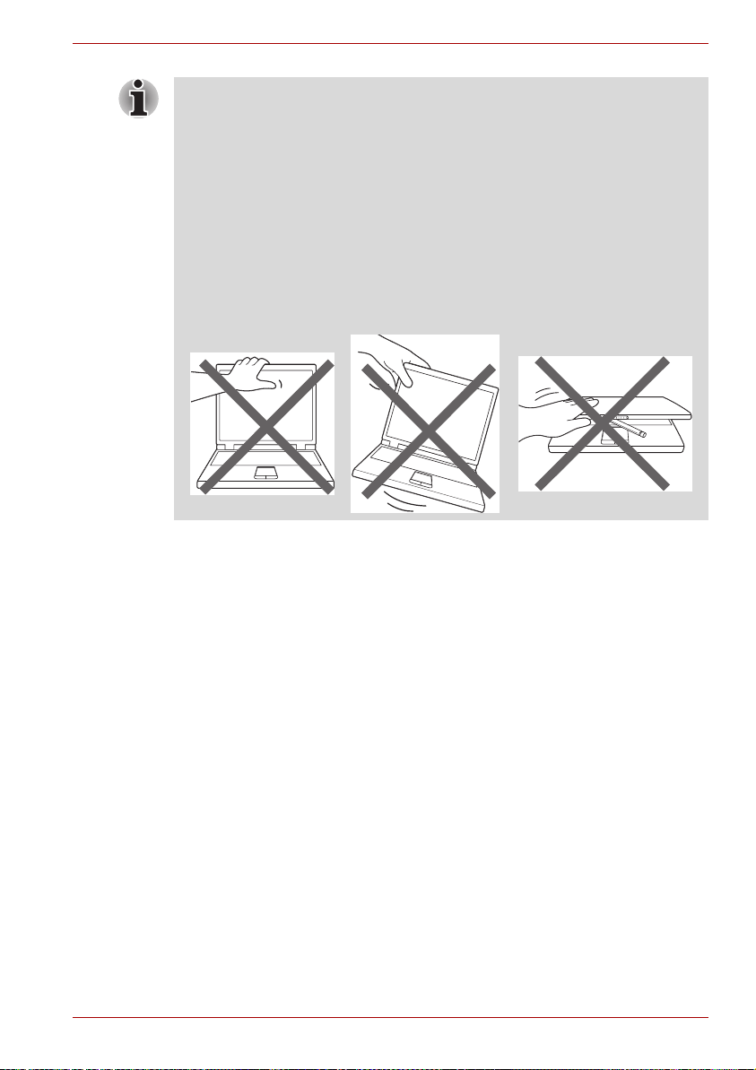
Pressure or impact damage
Do not apply heavy pressure to the computer or subject it to any form of
strong impact as this can damage the computer's components or otherwise
cause it to malfunction.
Mobile phones
Please be aware that the use of mobile phones can interfere with the audio
system. The operation of the computer will not be impaired in any way, but
it is recommended that a minimum distance of 30cm is maintained between
the computer and a mobile phone that is in use.
Instruction Manual for Safety and Comfort
All important information on the safe and proper use of this computer is
described in the enclosed Instruction Manual for Safety and Comfort. Be
sure to read it before using the computer.
General Precautions
User’s Manual xvii
Page 18

Introduction
This chapter provides an equipment checklist, and it identifies the
computer’s features, options and accessories.
Some of the features described in this manual may not function properly if
you use an operating system that was not pre-installed by TOSHIBA.
Equipment checklist
Carefully unpack your computer, taking care to save the box and packaging
materials for future use.
Hardware
Check to make sure you have all the following items:
■ TOSHIBA NB300 Portable Personal Computer
■ AC adaptor and power cord (2-pin plug or 3-pin plug)
■ Battery pack
Chapter 1
User’s Manual 1-1
Page 19

Software
The following Windows® operating system and utility software are
pre-installed.
■ Windows
■ Bluetooth Driver
■ Display Drivers for Windows
■ TOSHIBA HWSetup
■ TOSHIBA Supervisor Password
■ LAN Driver
■ Pointing Device Driver
■ Sound Driver for Windows
■ Wireless LAN Driver (Can be used only for Wireless LAN models)
■ TOSHIBA Disc Creator
■ TOSHIBA Recovery Media Creator
■ TOSHIBA ConfigFree
■ TOSHIBA PC Health Monitor
■ TOSHIBA Assist
■ TOSHIBA eco Utility
■ Online Manual
■ TOSHIBA NB300 series User's Manual (This manual)
®
7
TM
Introduction
Documentation
■ TOSHIBA NB300 Series User Information Guide
■ Instruction Manual for Safety and Comfort
If any of the items are missing or damaged, contact your dealer
immediately.
User’s Manual 1-2
Page 20

Features
Introduction
This computer incorporates the following features and benefits:
Processor
Built-in Your computer is equipped with one processor
and processor type varies depending on model.
To check which type of processor is included in
your model, open the TOSHIBA PC Diagnostic
Tool Utility by clicking Start
TOSHIBA
J
Utilities J PC Diagnostic Tool.
J
All programs J
Legal Footnote (CPU)*1
For more information on the CPU, please refer to the Legal Footnotes
section in Chapter 10 or click the *1 above.
Chipset
Chipset Intel® NM10 Express Chipset .
Memory
Slot PC2-5300 (DDR2-667) or compatible 1GB or
2GB memory module can be installed in the
memory slot.
Maximum system memory size is 2GB.
Video RAM Video RAM capacity is shared with main memory
with the proportion being allocated using
Dynamic Video Memory Technology.
Legal Footnote (Memory (Main System))*2
For more information regarding Memory (Main System), please refer to the
Legal Footnotes section in Chapter 10 or click the *2 above.
User’s Manual 1-3
Page 21
Disks
Introduction
Hard disk drive This computer supports SATA 3.0Gbps and is
■ Additional hard disk drive sizes may be introduced.
equipped with one of the following hard disk drive
(HDD) types. The capacity of each hard disk
drive model is different.
■ HDD
■ 160GB
■ 250GB
Please note that part of the hard disk drives
overall capacity is reserved as administration
space. Additional Hard Disk drive sizes may be
introduced.
Legal Footnote (Hard Disk Drive (HDD) Capacity)*4
For more information regarding Hard Disk Drive (HDD) Capacity, please
refer to the Legal Footnotes section in Chapter 10 or click the *4 above.
Keyboard
Built-in The internal keyboard provides the embedded
numeric overlay keys, dedicated cursor control
overlay keys, and Keys. The keyboard
is compatible with the IBM
Refer to Chapter 5, The Keyboard, for details.
®
enhanced keyboard.
Pointing Device
Built-in Touch Pad The integrated Touch Pad and control buttons in
the palm rest allow control of the on-screen
pointer and support functions such as the
scrolling of windows.
Power
Battery pack The computer is powered by one rechargeable
lithium-ion battery pack.
Legal Footnote (Battery life) *3
For more information regarding Battery life, please refer to the Disclaimer
section in Chapter 10 or click the *3 above.
User’s Manual 1-4
Page 22

Introduction
RTC battery The internal RTC battery backs up the Real Time
AC adaptor The AC adaptor provides power to the system
Clock (RTC) and calendar.
and recharges the batteries when they are low. It
comes with a detachable power cord which will
either have a 2-pin or 3-pin plug enclosure.
As the AC adaptor is universal, it can receive a
range of AC voltages from 100 to 240 volts,
however you should note that the output current
varies among different models. Using the wrong
adaptor can damage your computer. Refer to the
AC adaptor section in Chapter 2, The Grand Tour.
Ports
External monitor This port provides 15-pin, analog VGA port. This
port allows you to connect an external monitor to
the computer.
Universal Serial Bus
(USB 2.0)
The computer supports multiple Universal Serial
Bus ports that comply with the USB 2.0 standard.
The port with the ( ) has a USB Sleep and
Charge function.
Slots
Bridge media This slot lets you insert an SD™/SDHC™
memory card and MultiMediaCard™. Refer to
Chapter 8, Optional Devices.
Multimedia
Sound system The integrated sound system provides support
for the computer's internal speakers and
microphone, also allowing an external
microphone and headphones to be connected
via the appropriate jacks.
Web Camera Web Camera is a device that allows you to
record video or take photographs with your
computer. You can use it for video chatting or
video conferences using a communication tool
such as Windows Live Messenger. TOSHIBA
Web Camera Application will help you to add
various video effects to your video or photograph.
User’s Manual 1-5
Page 23

Introduction
Headphone jack This jack lets you connect speakers or a stereo
headphone. When you connect an external
speaker or headphones, the internal speaker is
automatically disabled.
Microphone jack A 3.5mm mini microphone jack enables
connection of a three-conductor mini jack for
stereo microphone input, and connection of a
stereo device for audio input.
Communications
LAN The computer has built-in support for Ethernet
LAN (10 megabits per second, 10BASE-T) and
Fast Ethernet LAN (100 megabits per second,
100BASE-TX).
Bluetooth
TM
Wireless LAN Some models are equipped with a Wireless LAN
Some models are equipped with Bluetooth
wireless communication function which
eliminates the need for cables between
electronic devices such as computers and
printers and mobile phones. When it is enabled,
Bluetooth provides the wireless personal area
network environment which is safe and
trustworthy, that is quick and easy to use.
module that is compatible with other LAN
systems based on Direct Sequence Spread
Spectrum/Orthogonal Frequency Division
Multiplexing radio technology that complies with
the IEEE 802.11 Standard.
■ The transmission speed over the wireless LAN, and the distance over
which the wireless LAN can reach, may vary depending on surrounding
electromagnetic environment, obstacles, access point design and
configuration, client design and software/hardware configurations. The
transmission rate described is the theoretical maximum speed as
specified under the appropriate standard - the actual transmission
speed will be lower than the theoretical maximum speed.
■ To enable or disable wireless communication, use the Hot Key FN+F8.
For more information see the Hot keys section in Chapter 5.
Legal Footnote (Wireless LAN)*7
For more information regarding Wireless LAN, please refer to the Legal
Footnotes section in Chapter 10 or click the *7 above.
User’s Manual 1-6
Page 24

Security
Introduction
Security lock slot Allows the connection of a security lock to anchor
the computer to a desk or other large object.
Software
The computer's internal display panel supports high-resolution video
graphics and can be set to a wide range of viewing angles for maximum
comfort and readability.
Operating system Windows
Software section at the front of this chapter.
TOSHIBA Utilities A number of utilities and drivers are preinstalled
to make your computer more convenient to use.
Refer to the Utilities and Applications section in
this chapter.
Plug and Play When you connect an external device to the
computer or when you install a component, Plug
and Play capability enables the system to
recognize the connection and make the
necessary configurations automatically.
®
7 is available. Refer to the preinstalled
User’s Manual 1-7
Page 25

Special features
The following features are either unique to TOSHIBA computers or are
advanced features which make the computer more convenient to use.
Access each function using the following procedures.
*1 To access the Power Options, click Start J Control Panel J System
and Security
Hot keys Hot keys are specific key combinations that let
J
Power Options.
you quickly change the system configuration
directly from the keyboard without running a
system program.
Introduction
Monitor automatic
power off
*1
This feature automatically cuts off power to the
computer's display panel when there is no
keyboard input for a specified time, with power
being restored the next time a key is pressed.
This can be specified in the Power Options.
HDD automatic
power off
*1
This feature automatically cuts off power to the
hard disk drive when it is not accessed for a
specified time, with power being restored when
the hard disk drive is next accessed. This can be
specified in the Power Options.
System automatic
Sleep/Hibernation
*1
Mode
This feature automatically shuts down the system
into either Sleep Mode or Hibernation Mode when
there is no input or hardware access for a
specified time. This can be specified in the Power
Options.
Keypad overlay A ten-key numeric keypad is integrated into the
keyboard. Please refer to the Keypad overlay
section in Chapter 5, The Keyboard, for
information on using this feature.
Power on password Two levels of password security, supervisor and
user, are available to prevent unauthorized
access to your computer.
Instant security A specific hot key function automatically locks the
system providing data security.
Intelligent power
supply
*1
A microprocessor in the computer's intelligent
power supply detects the battery's charge,
automatically calculates the remaining battery
capacity and protects electronic components
from abnormal conditions such as a voltage
overload from the AC adaptor. This can be
specified in the Power Options.
User’s Manual 1-8
Page 26

Battery save mode
*1
This feature lets you configure the computer in
order to save battery power. This can be
specified in the Power Options.
Introduction
Low battery
automatic
Hibernation Mode
When battery power is exhausted to the point that
computer operation cannot be continued, the
*1
system automatically enters Hibernation Mode
and shuts itself down. This can be specified in the
Power Options.
Heat dispersal
*1
To protect against overheating, the processor has
an internal temperature sensor so that, if the
computer's internal temperature rises to a certain
level, the cooling fan is turned on or the
processing speed is lowered. This can be
specified in the Power Options.
If the processor's temperature reaches an unacceptably high level with
either setting, the computer will automatically shut down to prevent any
damage - in this instance all unsaved data in memory will be lost.
TOSHIBA HDD
Protection
This feature which is for the hard disk drive
models uses the acceleration sensor built in the
computer to detect vibration, falls and shocks,
and automatically moves the hard disk drive’s
read/write head to a safe position in order to
reduce the risk of damage that could be caused
by head-to-disk contact. Refer to the Using the
Using the Hard Disk Drive (HDD) Protection
section in Chapter 4, Operating Basics for details.
The TOSHIBA HDD Protection function does not guarantee that the hard
disk drive will not be damaged.
User’s Manual 1-9
Page 27

Introduction
Hibernation Mode This feature lets you turn off the power to the
computer without exiting from your software. The
contents of main memory are automatically
saved to the hard disk drive so that when you
next turn the power on again, you can continue
working right where you left off. Refer to the
Turning off the power section in Chapter 3,
Getting Started, for more details.
Sleep Mode If you have to interrupt your work, you can use
this feature to allow you to turn off power to the
computer without exiting from your software. Data
is maintained in the computer's main memory so
that when you next turn on the power, you can
continue working right where you left off.
USB Wakeup
function
This function restores the computer from Sleep
Mode depending on the external devices
connected to the USB ports.
For example, if a mouse or USB keyboard is
connected to a USB port, moving the
mouse/keyboard will wakeup the computer.
The "USB Wakeup function" operates under
Windows
®
7 operating system and it works for all
USB ports.
TOSHIBA PC Health
Monitor
The TOSHIBA PC Health Monitor software
program monitors computer system functions
such as power consumption, the cooling system
and HDD Drop sensor. It alerts users of specific
system conditions via pop-up messages. It also
tracks the usage of the computer and related
devices, logging the service relevant information
on the computer's hard disk drive. Please refer to
the TOSHIBA PC Health Monitor section in
Appendix E.
TOSHIBA HDD/SSD
Alert
The TOSHIBA HDD/SSD Alert includes wizard
functions to monitor the Disk Drive operating
status.
HW Setup This utility allows you to customize your hardware
settings according to the way you work with the
computer and the peripherals you use.
User’s Manual 1-10
Page 28

TOSHIBA Value Added Package
Introduction
TOSHIBA Flash
Cards
TOSHIBA Power
Saver
TOSHIBA Zooming
Utility
TOSHIBA PC
Diagnostic Tool
The TOSHIBA Flash Cards provide a quick way
to modify selected system functions and to
launch applications.
■ Hot key function
■ TOSHIBA utility launcher function
TOSHIBA Power Saver provides you with the
features of more various power supply
managements.
This utility allows you to enlarge or reduce the
icon size on the Windows Desktop, or the zoom
factor associated with specific supported
applications.
The TOSHIBA PC Diagnostic Tool will display
basic system configuration information and allow
the functionality of some of the computer's built-in
hardware devices to be tested.
User’s Manual 1-11
Page 29

Utilities and Applications
This section describes the pre-installed utilities that come with the
computer and details how to start them. For further information on their
operation, please refer to each utility's online manual, help files or
README.TXT file.
Introduction
TOSHIBA ConfigFree TOSHIBA ConfigFree is a suite of utilities that
TOSHIBA Disc
Creator
TOSHIBA eco Utility TOSHIBA eco Utility helps you monitor your
improve the ease and control of communication
devices and network connections, help in the
identification of communication problems and
allow the creation of profiles if you need to switch
between different locations and communication
networks. To access this utility, click Start
Programs J TOSHIBA J ConfigFree.
You can create CD's and DVD's in a number of
formats including audio CD's that can be played
on a standard CD player, and data CD's/DVD's
which can store copies of the files and folders on
your computer's hard disk drive. This software
can be used on models with a DVD Super Multi
drive.
To start this utility, click Start J All Programs J
TOSHIBA
Creator.
power savings by showing approximate real time
power consumption. Furthermore, it shows
approximate accumulated power consumption
and approximate accumulated power savings
when using eco mode daily, weekly, and monthly.
You can track power savings by using eco mode
continuously.
J
CD&DVD Applications J Disc
J
All
User’s Manual 1-12
Page 30

Options
Introduction
You can add a number of options to make your computer even more
powerful and convenient to use. The following options are available:
Memory kit PC2-5300 (DDR2-667) or compatible 1GB or
2GB memory module can easily be installed in
the computer.
Battery Pack An additional battery pack can be purchased for
use as either a spare or replacement. Please
refer to Chapter 6, Power and Power-up Modes
for futher information.
AC Adaptor If you frequently use your computer at more than
one site, it may be convenient to purchase an
additional AC adaptor to be kept at each site in
order to remove the need to always carry the
adaptor with you.
USB FDD The USB floppy diskette drive accommodates
either a 1.44MB or 720KB floppy diskette through
connection to one of the computer's USB ports.
In use, please be aware that, while you cannot
format 720KB floppy diskettes under Windows
®
7, you are able to read and write to diskettes that
have already been formatted.
USB Optical Disc
The USB Optical Disc Drive can run CD/DVDs.
Drive
User’s Manual 1-13
Page 31

The Grand Tour
This chapter identifies the various components of your computer. Become
familiar with each component before you operate the computer.
Front with the display closed
The following figure shows the computer’s front with its display panel in the
closed position.
1. System indicators
Figure 2-1 Front of the computer with display closed
Chapter 2
1
System indicators
The LED system indicators for specific computer operations glow when
those operations are in progress.
Figure 2-2 System indicators
User’s Manual 2-1
Page 32

The Grand Tour
DC IN The DC IN indicator normally glows green when
power is being correctly supplied from the AC
power adaptor. However, If the output voltage
from the adaptor is abnormal, or if the computer's
power supply malfunctions, this indicator will go
out.
Power The Power indicator normally glows green when
the computer is turned on. However, if you turn
the computer off into Sleep Mode, this indicator
will flash amber - approximately two seconds on,
one second off - both while the system is shutting
down and while it remains in Sleep Mode.
Battery The Battery indicator shows the condition of the
battery's charge - green indicates the battery is
fully charged, amber indicates the battery is
charging, and flashing amber indicates a low
battery condition. Please refer to Chapter 6,
Power and Power-up Modes for more information
on this feature.
HDD The HDD indicator glows green whenever the
computer is accessing the built-in hard disk drive.
Bridge media slot The Bridge media slot indicator glows green
when the computer is accessing the Bridge
media slot.
Wireless
communication
The Wireless communication indicator glows
amber when the Bluetooth and Wireless LAN
functions are turned on. Only some models are
equipped with Bluetooth and Wireless LAN
functions.
Wireless WAN
communication
The Wireless WAN communication indicator
glows or blinks blue when the Wireless WAN
function is on. The indicator will glow or blink in
order to indicate the connection status of the
Wireless WAN function. A Wireless WAN module
must be installed to use this function. Some
models are equipped with a Wireless WAN
module.
User’s Manual 2-2
Page 33
The Grand Tour
Left side
Arrow Lock
When the Arrow indicator lights green, you can
use the dark gray labeled keys on the keypad
overlay as cursor keys.
Numeric Lock
When the Numeric Lock indicator glows green,
you can use the dark gray labelled keys on the
keypad overlay for numeric input.
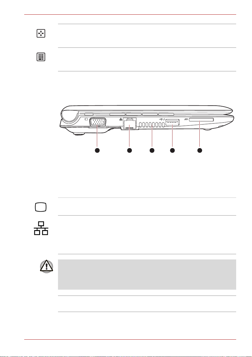
The following figure shows the computer's left side.
1 2 3 4 5
1. External monitor port
2. LAN jack
3. Thermal vent holes
4. Universal Serial Bus(USB2.0) port
5. Bridge media slot
Figure 2-3 The left side of the computer
External monitor
port
This port allows you to connect an external
monitor to the computer.
LAN jack This jack lets you connect to a LAN. The adaptor
has built-in support for Ethernet LAN (10
megabits per second, 10BASE-T) and Fast
Ethernet LAN (100 megabits per second,
100BASE-TX). Refer to Chapter 4, Operating
Basics, for details.
■ Do not connect any cable other than a LAN cable to the LAN jack. It
could cause damage or malfunction.
■ Do not connect the LAN cable to a power supply. It could cause
damage or malfunction.
Thermal vent holes The thermal vent holes help keep the processor
from overheating.
User’s Manual 2-3
Page 34

The Grand Tour
Do not block the thermal vent holes. Keep foreign metal objects, such as
screws, staples and paper clips, out of the cooling vents. Foreign metal
objects can create a short circuit, which can cause damage and fire,
possibly resulting in serious injury.
Universal Serial Bus
(USB 2.0) port
The Universal Serial Bus port, which complies
with the USB 2.0 standard, is provided on the left
hand side of the computer. The port with the icon
() has USB Sleep and Charge function.
Keep foreign metal objects, such as screws, staples and paper clips, out of
the USB connectors. Foreign metal objects can create a short circuit,
which can cause damage and fire, possibly resulting in serious injury.
Please note that it is not possible to confirm the operation of all functions of
all USB devices that are available. In view of this it may be noted that
some functions associated with a specific device might not operate
properly.
Bridge media slot
This slot lets you insert an SD™/SDHC™
memory card and MultiMediaCard™. Refer to
Chapter 8, Optional Devices.
Keep foreign metal objects, such as screws, staples and paper clips, out of
the Bridge media slot. Foreign metal objects can create a short circuit,
which can cause damage and fire, possibly resulting in serious injury.
User’s Manual 2-4
Page 35
Right side
The Grand Tour
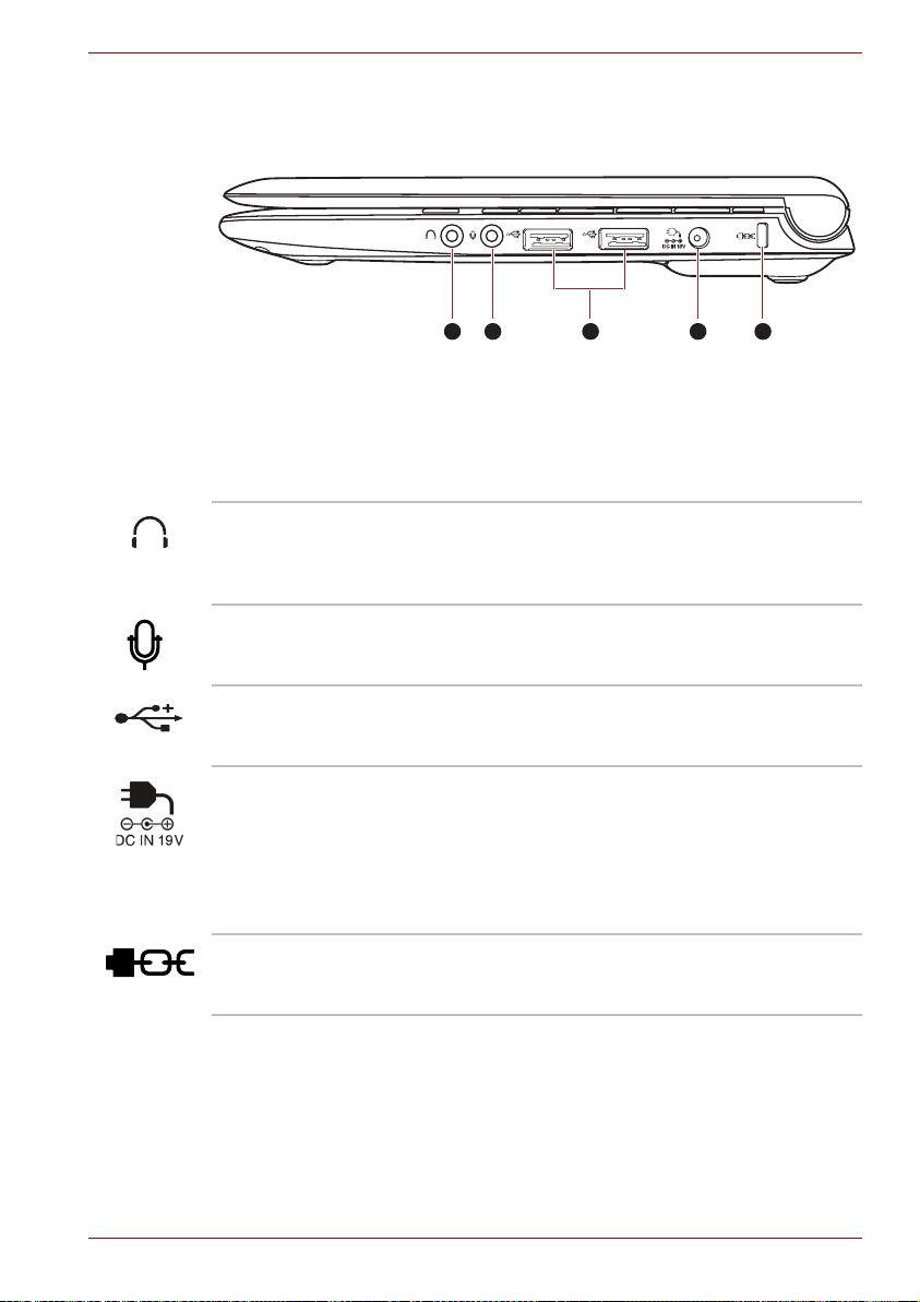
The following figure shows the computer’s right side.
3 421 5
1. Headphone jack
2. Microphone jack
3. Universal Serial Bus (2.0) port
4. DC IN 19V jack
5. Security lock slot
Figure 2-4 The right side of the computer
Headphone jack A standard 3.5 mm mini headphone jack enables
connection of stereo headphones or other device
for audio output. When you connect headphones,
the internal speaker is automatically disabled.
Microphone jack A standard 3.5 mm mini microphone jack enables
connection of a microphone or other device for
audio input.
Universal Serial Bus
(USB 2.0) port
Two Universal Serial Bus ports, which comply
with the USB 2.0 standard, are provided on the
right side of the computer.
DC IN 19V jack The AC adaptor connects to this jack in order to
power the computer and charge its internal
batteries. Please note that you should only use
the model of AC adaptor supplied with the
computer at the time of purchase - using the
wrong AC adaptor can cause damage to the
computer.
Security lock slot A security cable can be attached to this slot and
then connected to a desk or other large object in
order to deter theft of the computer.
User’s Manual 2-5
Page 36
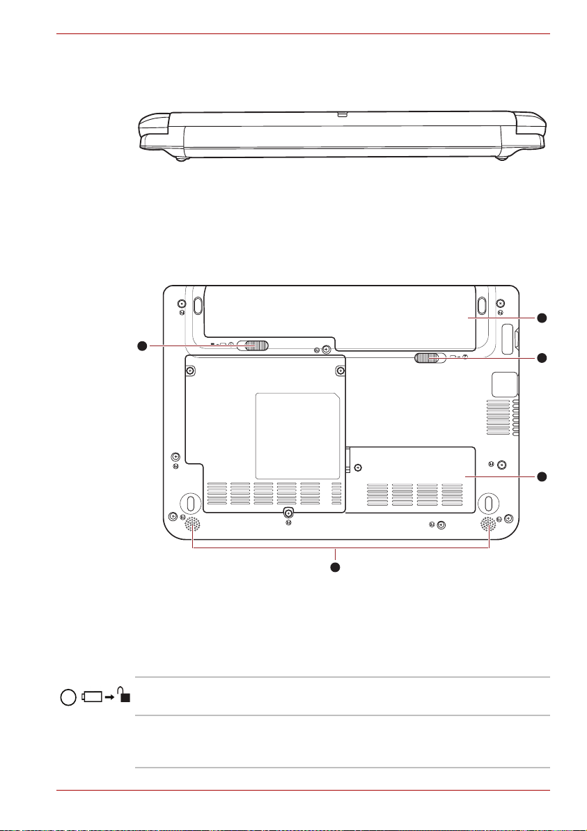
Back side
Figure 2-5 shows the computer’s back side.
Underside
The following figure shows the underside of the computer. You should
ensure that the display is closed before the computer is turned over to
avoid causing any damage.
The Grand Tour
Figure 2-5 The computer’s back side.
5
1
2
1. Battery safety lock
2. Speaker
3. Memory module slot
4. Battery release latch
5. Battery pack
Figure 2-6 The underside of the computer
1
Battery safety lock Slide this latch into its 'Unlock' position in order to
release the battery pack ready for removal.
4
3
Speaker The speaker emits sound generated by your
software as well as audio alarms, such as low
battery condition, generated by the system.
User’s Manual 2-6
Page 37

The Grand Tour
Memory module slot The memory module slot is located here. The
memory module slot allows for the replacement
with an additional memory module. Please refer
to the Additional memory module section in
Chapter 8, Optional Devices for more
information.
2
in order to release the battery pack ready for
removal.
For more detailed information on removing the
battery pack please refer to Chapter 6, Power
and Power-up Modes.
Battery pack The battery pack provides power to the computer
when the AC adaptor is not connected. For more
detailed information on the use and operation of
the battery pack please refer to Chapter 6, Power
and Power-up Modes.
Battery release latch Slide and hold this latch into its 'Unlock' position
User’s Manual 2-7
Page 38
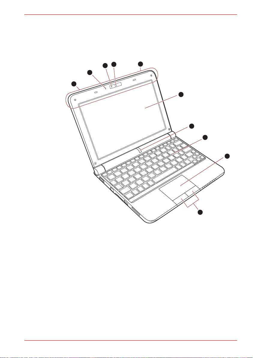
Front with the display open
This section shows the computer with the display panel open. In order to
open the display, lift the display panel up and position it at a comfortable
viewing angle for you.
The Grand Tour
3
2
1
9
1. Microphone
2. Web Camera LED
3. Web Camera
4. Display Screen
5. Power Button
*6. Keyboard
7. Touch Pad
8. Touch Pad control buttons
9. Wireless LAN antenna (Not shown)
Wireless WAN antenna (for some models) (Not shown)
* Appearance of the Keyboard may be different among models.
Figure 2-7 The front of the computer with display open
9
4
5
6
7
8
User’s Manual 2-8
Page 39

The Grand Tour
Microphone A built-in microphone allows you to import and
record sounds for your application - please refer
to the Sound system section in Chapter 4,
Operating Basics for more information.
Web Camera LED
The Web Camera LED glows blue when the Web
Camera is working.
Web Camera Web Camera is a device that allows you to
record video or take photographs with your
computer. You can use it for video chatting or
video conferencing using a communication tool
such as Windows Live Messenger. TOSHIBA
Web Camera Application will help you to add
various video effects to your video or photograph.
Enables the transmission of video and use of
video chat via the internet using specialized
applications.
Ensure that you remove the protective plastic film
that covers the Web Camera before using it.
Display screen Please be aware that, when the computer is
operating on the AC adaptor, the image
displayed on the internal screen will be
somewhat brighter than when it operates on
battery power. This difference in brightness
levels is intended to save power when operating
on batteries. For more information on the
computer's display, please refer to the Display
Controller section in Appendix B.
Power button Press this button to turn the computer's power on
and off.
The power button is disabled while the display
panel is closed.
Touch Pad The Touch Pad mouse control device located in
the center of the palm rest is used to control the
movement of the on-screen pointer. For more
information, please refer to the Using the Touch
Pad section in Chapter 4, Operating Basics.
Touch Pad control
buttons
The control buttons located below the Touch Pad
allow you to select menu items or manipulate text
and graphics as designated by the on-screen
pointer.
User’s Manual 2-9
Page 40
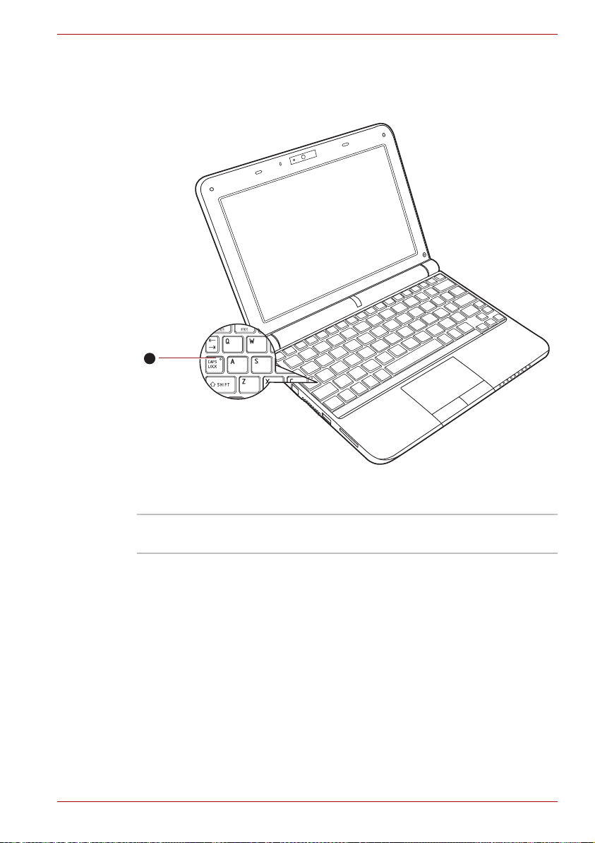
Keyboard indicators
When the CAPS LOCK indicator glows, the keyboard will produce capitals
when any letter is typed.
1
The Grand Tour
1. CAPS LOCK indicator
Figure 2-8 Keypad indicators
CAPS LOCK This indicator glows green when letter keys are
locked into their uppercase format.
User’s Manual 2-10
Page 41

AC adaptor
The AC adaptor can automatically adjust to any voltage ranging from 100 to
240 volts volts and to a frequency of either 50 or 60 hertz, enabling you to
use this computer in almost any country/region. The adaptor converts AC
power to DC power and reduces the voltage supplied to this computer.
To recharge the battery, simply connect the AC adaptor to a power source
and to the computer. Please refer to Chapter 6, Power and Power-up
Modes for further information.
The Grand Tour
Figure 2-9 The AC adaptor (2-pin plug)
Figure 2-10 The AC adaptor (3-pin plug)
■ Depending on the model in question, either a 2-pin or 3-pin
adaptor/power lead will be bundled with the computer.
■ Do not use a 3-pin to 2-pin conversion plug.
■ The supplied power cord conforms to safety rules and regulations in
the region the product is bought and should not be used outside of this
region. In order to use the adaptor/computer in other regions, you
should buy a power cord that conforms to the safety rules and
regulations in that particular region.
Always use the TOSHIBA AC adaptor that was included with your
computer, or use AC adaptors specified by TOSHIBA to avoid any risk of
fire or other damage to the computer. Use of an incompatible AC adaptor
could cause fire or damage to the computer possibly resulting in serious
injury.
User’s Manual 2-11
Page 42

Getting Started
This chapter provides basic information to start using your computer. It
covers the following topics:
■ All users should be sure to read the section Starting up for the first time.
■ Be sure to read the enclosed Instruction Manual for Safety and Comfort
for information on the safe and proper use of this computer. It is
intended to help you be more comfortable and productive while using a
notebook computer. By following the recommendations in it you may
reduce your chance of developing a painful or disabling injury to your
hand, arms, shoulders or neck.
■ Connecting the AC adaptor
■ Opening the display
■ Turning on the power
■ Starting up for the first time
■ Turning off the power
■ Restarting the computer
■ System Recovery Options
■ Creating Recovery Media
■ Restoring the pre-installed software from the Recovery hard disk drive
■ Restoring the pre-installed software from your created Recovery Media
Chapter 3
User’s Manual 3-1
Page 43

Getting Started
■ Use a anti-virus software and make sure it is updated regularly.
■ Never format storage media without checking its content - formatting
destroys all stored data.
■ It is a good idea to periodically back up the internal hard disk drive or
other main storage device to external media. General storage media is
not durable or stable over long periods of time and under certain
conditions may result in data loss.
■ Before you install a device or application, save any data in memory to
the hard disk drive or other storage media. Failure to do so may result
in the loss of data.
User’s Manual 3-2
Page 44

Connecting the AC adaptor
Attach the AC adaptor when you need to charge the battery or you want to
operate from AC power. It is also the fastest way to get started, because
the battery pack will need to be charged before you can operate from
battery power.
The AC adaptor can be connected to any power source supplying from 100
to 240 volts and 50 or 60 hertz. For details on using the AC adaptor to
charge the battery pack, refer to Chapter 6, Power and Power-up Modes.
■ Always use the TOSHIBA AC adaptor that was included with your
computer or use AC adaptors specified by TOSHIBA to avoid any risk
of fire or other damage to the computer. Use of an incompatible AC
adaptor could cause fire or damage to the computer possibly resulting
in serious injury. TOSHIBA assumes no liability for any damage caused
by use of an incompatible adaptor.
■ Never plug the AC adaptor into a power source that does not
correspond to both the voltage and the frequency specified on the
regulatory label of the unit. Failure to do so could result in a fire or
electric shock, possibly resulting in serious injury.
■ Always use or purchase power cables that comply with the legal
voltage and frequency specifications and requirements in the country of
use. Failure to do so could result in a fire or electric shock, possibly
resulting in serious injury.
■ The supplied power cord conforms to safety rules and regulations in
the region the product is bought and should not be used outside this
region. For use in other regions, please buy power cords that conform
to safety rules and regulations in the particular region.
■ Do not use a 3-pin to 2-pin conversion plug.
■ When you connect the AC adaptor to the computer, always follow the
steps in the exact order as described in the User’s Manual. Connecting
the power cable to a live electrical outlet should be the last step
otherwise the adaptor DC output plug could hold an electrical charge
and cause an electrical shock or minor bodily injury when touched. As
a general safety precaution, avoid touching any metal parts.
■ Never place your computer or AC adaptor on a wooden surface,
furniture, or any other surface that could be marred by exposure to heat
since the computer base and AC adaptor's surface increase in
temperature during normal use.
■ Always place your computer or AC adaptor on a flat and hard surface
that is resistant to heat damage.
Refer to the enclosed Instruction Manual for Safety and Comfort for
detailed precautions and handling instructions.
Getting Started
User’s Manual 3-3
Page 45

Getting Started
1. Connect the power cord to the AC adaptor.
Figure 3-1 Connecting the power cord to the AC adaptor (2-pin plug)
Figure 3-2 Connecting the power cord to the AC adaptor (3-pin plug)
Either a 2-pin or 3-pin adaptor/cord will be included with the computer
depending on the model.
2. Connect the AC adaptor's DC output plug to the DC IN 19V jack on the
right side of the computer.
Figure 3-3 Connecting the adaptor to the computer
3. Plug the power cord into a live wall outlet - the Battery and DC IN
indicators on the front of the computer should glow.
User’s Manual 3-4
Page 46

Opening the display
The display panel can be opened to a wide range of angles for optimal
viewing.
While holding down the palm rest with one hand so that the main body of
the computer is not raised, slowly lift the display panel - this will allow the
angle of the display panel to be adjusted to provide optimum clarity.
1
Getting Started
1. Display panel
Figure 3-4 Opening the display
Use reasonable care when opening and closing the display panel. Opening
it vigorously or slamming it shut could damage the computer.
User’s Manual 3-5
Page 47
Getting Started
■ When opening the panel, please be careful not to force it beyond the
point where it moves easily.
■ Be careful not to open the display panel too far as this could put stress
on the display panel’s hinges and cause damage.
■ Do not press or push on the display panel.
■ Do not lift the computer by the display panel.
■ Do not close the display panel with pens or any other objects left in
between the display panel and the keyboard.
■ When opening or closing the display panel, place one hand on the
palm rest to hold the computer in place and use the other hand to
slowly open or close the display panel (Do not use excessive force
when opening or closing the display panel).
User’s Manual 3-6
Page 48

Turning on the power
This section describes how to turn on the power - the Power indicator will
then indicate the status. Please refer to the Monitoring of power condition
section in Chapter 6, Power and Power-up Modes for more information.
■ After you turn on the power for the first time, do not turn it off until you
have set up the operating system. Please refer to the section Starting
up for the first time for more information.
■ The power button is disabled while the display panel is closed.
■ Volume cannot be adjusted during Windows Setup.
1. Open the computer's display panel.
2. Press the computer's power button.
Getting Started
1
1. Power button
Figure 3-5 Turning on the power
Starting up for the first time
The Windows® 7 Welcome screen will be the first screen displayed when
you turn on the power. Follow the on-screen instructions on each screen in
order to properly install the operating system.
When it is displayed, be sure to read the Software License Terms
carefully.
User’s Manual 3-7
Page 49
Turning off the power
The power can be turned off in one of three modes, either Shut Down
Mode, Hibernation Mode or Sleep Mode.
Shut Down Mode
When you turn off the power in Shut Down Mode no data will be saved and
the computer will boot to the operating system's main screen the next time
it is turned on.
1. If you have entered data, either save it to the hard disk drive or to other
storage media.
■ Make sure the Hard Disk Drive indicator is off. If you turn off the power
while a disk (disc) is being accessed, you may lose data or damage the
disk.
■ Never turn off the power while an application is running. Doing so could
cause loss of data.
■ Never turn off the power, disconnect an external storage device or
remove storage media during data read/write. Doing so can cause data
loss.
2. Click Windows Start button, then click the Shut down button .
3. Turn off any peripheral devices connected to your computer.
Do not turn the computer or peripheral devices back on immediately - wait
a short period to avoid any potential damage.
Getting Started
Hibernation Mode
The Hibernation Mode feature saves the contents of memory to the hard
disk drive when the computer is turned off so that, the next time it is turned
on, the previous state is restored. Please note that the Hibernation Mode
feature does not save the status of any peripheral devices connected to the
computer.
■ Save your data. While entering Hibernation Mode, the computer saves
the contents of memory to the hard disk drive. However, for safety
sake, it is best to save your data manually.
■ Data will be lost if you remove the battery or disconnect the AC adaptor
before the save is completed. Wait for the Hard Disk Drive indicator to
go out.
■ Do not install or remove a memory module while the computer is in
Hibernation Mode. Data will be lost.
Benefits of Hibernation Mode
The Hibernation Mode feature provides the following benefits:
■ Saves data to the hard disk drive when the computer automatically
shuts down because of a low battery condition.
User’s Manual 3-8
Page 50

Getting Started
■ You can return to your previous working environment immediately when
you turn on the computer.
■ Saves power by shutting down the system when the computer receives
no input or hardware access for the time period set by the System
Hibernate feature.
■ Allows the use of the panel power off feature.
Starting Hibernation Mode
You can also enable Hibernation Mode by pressing FN + F4 - please refer
to Chapter 5, The Keyboard, for further details.
To enter Hibernation Mode, follow the steps below.
1. Click Windows Start button.
2. Point to .
3. Select Hibernate.
Automatic Hibernation Mode
The computer can be configured to enter Hibernation Mode automatically.
In order to define these settings, you can follow the steps as described
below:
1. Open the Control Panel.
2. Open System and Security and open Power Options.
3. Select Choose what the power button does.
4. Enable the desired hibernation settings for When I press the power
button and When I close the lid.
5. Click the Save changes button.
Data save in Hibernation Mode
When you turn off the power in Hibernation Mode, the computer will take a
moment to save the current data in memory to the hard disk drive. During
this time, the Hard Disk Drive indicator will glow.
After you turn off the computer, and the content of memory has been saved
to the hard disk drive, turn off the power to any peripheral devices.
Do not turn the computer or peripheral devices back on immediately - wait
a short period to avoid any potential damage.
Sleep Mode
In Sleep mode the power remains on, but the processor and all other
devices are in Sleep mode.
User’s Manual 3-9
Page 51

Getting Started
Turning Off Your Computer where Electronic Devices are Regulated or
Controlled.
When you have to turn off your computer aboard an aircraft or in places
where electronic devices are regulated or controlled, always shut down the
computer completely or put the computer into Hibernation mode instead of
allowing it to go into Sleep mode. Also ensure that you disable wireless
communication and turn off any wireless communication devices. while in
Sleep mode the computer operating system may reactivate itself to run
pre-programmed tasks or to preserve unsaved data, and might interfere
with aviation or other systems, possibly causing serious injury.
■ Before entering Sleep Mode, be sure to save your data.
■ Do not install or remove a memory module while the computer is in
Sleep Mode. The computer or the memory module could be damaged.
■ Do not remove the battery pack while the computer is in Sleep Mode
(unless the computer is connected to an AC power source). Data in
memory could be lost.
■ To enable or disable wireless communication, use the Hot Key FN+F8.
For more information see the Hot keys section in Chapter 5.
■ You can disable Wireless communication in BIOS Setup or HW Setup.
After disabling the wireless communication function, confirm the
Wireless communication indicator is turned off. If the Wireless
communication indicator is turned on, the wireless communication is
enabled and radio waves from the computer may affect electronic
devices. For details of BIOS Setup and HW Setup, please refer to
Chapter 7.
Benefits of Sleep Mode
The Sleep Mode feature provides the following benefits:
■ Restores the previous working environment more rapidly than does the
Hibernation Mode feature.
■ Saves power by shutting down the system when the computer receives
no input or hardware access for the time period set by the System
Sleep Mode feature.
■ Allows the use of the panel power off feature.
Executing Sleep Mode
You can also enable Sleep Mode by pressing FN + F3 - please refer to
Chapter 5, The Keyboard, for further details.
You can enter Sleep Mode in one of three ways:
1. Click Windows Start button, point to , and then click Sleep.
2. Close the display panel. This feature must be enabled. Refer to the
Power Options in the Control Panel.
User’s Manual 3-10
Page 52

3. Press the power button. This feature must be enabled. Refer to the
Power Options in the Control Panel.
When you turn the power back on, you can continue where you left when
you shut down the computer.
■ When the computer is in Sleep Mode, the Power indicator will blink
amber.
■ If you are operating the computer on battery power, you can lengthen
the overall operating time by turning it off into Hibernation Mode - Sleep
Mode will consume more power while the computer is off.
Sleep Mode limitations
Sleep Mode will not function under the following conditions:
■ Power is turned back on immediately after shutting down.
■ Memory circuits are exposed to static electricity or electrical noise.
Restarting the computer
Certain conditions require that you reset the computer, for example if:
■ You change certain computer settings.
■ An error occurs and the computer does not respond to your keyboard
commands.
If you need to restart the computer, there are two ways this can be
achieved:
1. Click Start then click the arrow button and select Restart from the
menu.
2. Press CTRL, ALT and DEL simultaneously (once) to display the menu
window, then click th arrow button in the lower right corner of the
screen, then select Restart.
3. Press the power button and hold it down for five seconds. Once the
computer has turned itself off, wait between ten and fifteen seconds
before turning the power on again by pressing the power button.
Getting Started
System Recovery Options
A hidden partition is allocated on the hard disk drive for the System
Recovery Options.
This partition stores files which can be used to repair the system in the
event of a problem.
The System Recovery Options feature will be unusable if this partition is
deleted.
User’s Manual 3-11
Page 53

System Recovery Options
The System Recovery Options feature is installed on the hard disk when
shipped from the factory. The System Recovery Options menu includes
tools to repair startup problems, run diagnostics or restore the system.
See the Windows Help and Support content for more information about
Startup Repair.
The System Recovery Options can also be run manually to repair
problems.
The procedure is as follows. Follow the instructions shown on the
on-screen menu.
1. Turn off the computer.
2. While holding the F8 key, turn on the computer.
3. The Advanced Boot Options menu will be displayed.
Use the arrow keys to select Repair Your Computer and press
ENTER.
4. Follow the on-screen instructions.
Getting Started
The Windows® 7 Create a System Image feature can be used on all
versions of Windows
location, the edition has to be either Professional or Ultimate.
®
7. However, to save the backup on a network
Creating Recovery Media
This section describes how to create Recovery Media.
■ Be sure to connect the AC adaptor when you create Recovery Media.
■ Be sure to close all other software programs except the Recovery
Media Creator.
■ Do not run software such as screen savers which can put a heavy load
on the CPU.
■ Operate the computer at full power.
■ Do not use power-saving features.
■ Do not write to the media when the anti-virus software is running. Wait
for it to finish, then disable virus detection programs including any
software that checks files automatically in the background.
■ Do not use utilities, including those intended to enhance hard disk drive
access speed. They may cause unstable operation and damage data.
■ Do not shut down/log off or Sleep/Hibernate while writing or rewriting
the disc.
■ Set the computer on a level surface and avoid places subjected to
vibrations such as airplanes, trains, or cars.
■ Do not use on unstable tables or other any other unstable surfaces.
■ You can use DVD media when you connect the external ODD.
User’s Manual 3-12
Page 54

Getting Started
A recovery image of the software on your computer is stored on the hard
disk drive, and can be copied to either DVD or USB Flash Memory by using
the following steps:
1. Select either blank DVD or USB Flash Memory.
2. The application will allow you to choose from a variety of different media
onto which the recovery image can be copied including DVD-R, DVD-R
DL, DVD-RW, DVD+R, DVD+R DL, DVD+RW and USB Flash Memory.
■ Please note that some of the above media may not be compatible with
the optical disc drive installed into your computer. You should therefore
verify the optical disc drive supports the blank media you have chosen
before proceeding.
■ USB Flash Memory will be formatted and all the data in the USB Flash
Memory will be lost when proceeding.
3. Turn on your computer and allow it to load the Windows® 7 operating
system from the hard disk drive as normal.
4. Insert the media.
■ Insert the first blank DVD into the optical disc drive tray, or
■ Insert the blank USB Flash Memory into one available USB port.
®
5. Double click the Recovery Media Creator icon on the Windows
desktop, or select the application from Start Menu.
6. After Recovery Media Creator starts, select the type of media and the
title you wish to copy, and then click the Create button.
7
Restoring the pre-installed software from the Recovery hard disk
drive
A portion of the total hard disk drive space is configured as a hidden
recovery partition. This partition stores files which can be used to restore
pre-installed software in the event of a problem.
If you subsequently set up your hard disk drive again, do not change,
delete or add partitions in a manner other than specified in the manual,
otherwise you may find that space for the required software is not available.
In addition, if you use a third-party partitioning program to reconfigure the
partitions on your hard disk drive, you may find that it becomes impossible
to setup your computer.
When the sound mute feature has been activated by pressing the Mute
panel (Fn+ESC), be sure to disable this to allow sounds to be heard before
starting the restore process. Please refer to Chapter 5, The Keyboard, for
further details.
You can not use System Recovery Options if restoring the pre-installed
software without System Recovery Options.
User’s Manual 3-13
Page 55

Getting Started
When you reinstall the Windows operating system, the hard disk will be
reformatted and all data will be lost.
1. Turn off your computer.
2. While holding down 0 (zero) key on the keyboard, turn on your
computer.
3. A menu will be displayed from which you should follow the on-screen
instructions.
Restoring the pre-installed software from your created Recovery
Media
If the pre-installed files are damaged, you are able to either use the
Recovery Media you have created or the hard disk drive recovery process
to restore the computer to the state it was in when you originally received it.
To perform this restoration, follow the steps below:
When the sound mute feature has been activated by pressing the FN +
ESC key, be sure to disable this to allow sounds to be heard before starting
the restore process. Please refer to Chapter 5, The Keyboard, for further
details.
You can not use System Recovery Options if restoring the pre-installed
software without System Recovery Options.
When you reinstall the Windows operating system, the hard disk will be
reformatted and all data will be lost.
1. Load the Recovery Media into the optical disc drive or USB port and
turn off the computer's power.
2. While holding down F12 key on the keyboard, turn on your computer -
when TOSHIBA Leading Innovation>>> appears, release the F12
key.
3. Use the up and down cursor keys to select either "optical disc drive" or
"USB Flash Memory" from the menu. Please refer to the Boot Priority
section in Chapter 7, HW Setup and Passwords for further information.
4. A menu will be displayed from which you should follow the on-screen
instructions.
When drivers/utilities are installed, you can setup the respective
drivers/utilities from the following place.
To open the setup files, Click Start
Applications and Drivers.
User’s Manual 3-14
J
All Programs J TOSHIBA J
Page 56

Operating Basics
This chapter describes the basic operations of your computer and
highlights the precautions that should be taken when using it.
Using the Touch Pad
To use the Touch Pad, simply touch and move your fingertip across it in the
direction you want the on-screen pointer to go.
Chapter 4
1
2
1. Touch Pad
2. Touch Pad control buttons
Figure 4-1 Touch Pad and Touch Pad control buttons
User’s Manual 4-1
Page 57

The two buttons below the Touch Pad are used like the buttons on a
standard mouse - press the left button to select a menu item or to
manipulate text or graphics designated by the pointer, and press the right
button to display a menu or other function depending on the software you
are using.
You can also tap the Touch Pad to perform functions similar to those of the
left button on a standard mouse.
Click: Tap onc e
Double-click: Tap twice
Drag and drop: Tap to select the item(s) you want to move, leave your
finger on the Touch Pad after the second tap and then move the item(s)
to their new destination.
Scroll:
Vertical: Move your finger up or down the right edge of the TouchPad.
Horizontal: Move your finger left or right along the bottom edge of the
TouchPad.
USB Sleep and Charge function
Your computer can supply USB bus power (DC5V) to the USB port even
when the power of the computer is turned OFF. "Power OFF" includes
Sleep mode, hibernation mode or shutdown state.
This function can only be used for ports that support the USB Sleep and
Charge function (hereinafter called "compatible ports").
Compatible ports are USB ports that have the ( ) symbol icon.
You can use the USB Sleep and Charge function to charge certain USB
compatible external devices such as mobile phones or portable digital
music players.
However, the USB Sleep and Charge function may not work with certain
external devices even if they are compliant with the USB specification. In
those cases, turn the power of the computer ON to charge the device.
Operating Basics
User’s Manual 4-2
Page 58

Operating Basics
■ The USB Sleep and Charge function only works for compatible ports.
This function is disabled in the default setting.
■ When USB Sleep and Charge function is set to [Enabled], USB bus
power (DC5V) will be supplied to compatible ports even when the
power of the computer is turned OFF.
USB bus power (DC5V) is similarly supplied to the external devices
which are connected to the compatible ports. However, some external
devices cannot be charged solely by supplying USB bus power
(DC5V).
As for the specifications of the external devices, please contact the
device manufacturer or check the specifications of the external devices
thoroughly before use.
■ Using the USB sleep and charge function to charge external devices
will take longer than charging the devices with their own chargers.
■ If USB Sleep and Charge function is enabled, the computer’s battery
will discharge during hibernation or when the computer is turned off. It
is recommended that you connect the AC adaptor to the computer
when enabling the USB Sleep and Charge function.
■ External devices connected to the USB bus power (DC5V) function that
interfaces with the power ON/OFF of the computer may always be in
an operational state.
■ When there is a current overflow of the external devices connected to
the compatible ports, USB bus power (DC5V) supply may be stopped
for safety reasons.
Metal paper clips or hair pins/clips will generate heat if they come into
contact with USB ports. Do not allow USB ports to come into contact with
metal products, for example when carrying the computer in your bag.
Starting the USB Sleep and Charge Utility
To start the utility, click Start J All Programs J TOSHIBA J Utilities J
USB Sleep and Charge.
You can set Typical Mode/Alternate Mode/Disable USB sleep and charge
function also in BIOS Setup menu. Please refer to Accessing HW Setup in
Chapter 7 for how to start BIOS Setup Menu.
Enabling USB Sleep and Charge
This utility can be used to enable and disable the USB Sleep and Charge
function.
Check the "USB Sleep and Charge" check box. In the default state this
function is disabled.
User’s Manual 4-3
Page 59

Power supply mode settings
Your PC has multiple charging modes so that many different USB devices
can be supported for USB Sleep and Charge function. Typical Mode
(Default) is suitable for a wide range of digital audio players.
However, determining which mode is suitable for your USB device is
unknown without trying. Try each mode, using the following procedure,
from Typical Mode to Alternate Mode(*1) to find the suitable mode for your
USB device to charge.
This function may not be able to be used with some connected external
devices even if the appropriate mode is selected. In this situation, clear the
"USB Sleep and Charge" check box and stop using this function.
*1. Some computers may not support all modes.
Battery Settings
This utility can be used to specify the lower limit of remaining battery life for
USB Sleep and Charge. Move the slider bar to specify the lower limit. If the
remaining battery life falls below the setting, the "USB Sleep and Charge
function" will be stopped. Unchecking the "Enable under Battery Mode"
check box sets the utility to only charge when the AC adaptor is connected.
TOSHIBA Disc Creator
You can use TOSHIBA Disc Creator when you connect External ODD.
Operating Basics
Please be aware of the following limitations when you use the TOSHIBA
Disc Creator:
■ DVD Video cannot be created using TOSHIBA Disc Creator.
■ DVD Audio cannot be created using TOSHIBA Disc Creator.
■ You cannot use TOSHIBA Disc Creator's 'Audio CD for Car or Home
CD Player' function to record music to DVD-R, DVD-R (Dual Layer),
DVD-RW, DVD+R, DVD+R (Double Layer) or DVD+RW media.
■ Do not use the 'Disc Backup' function of TOSHIBA Disc Creator in order
to copy DVD Video or DVD-ROM material that has copyright protection.
■ DVD-RAM discs cannot be backed up using the 'Disc Backup' function
of TOSHIBA Disc Creator.
■ You cannot back up CD-ROM, CD-R or CD-RW media to DVD-R, DVD-
R (Dual Layer) or DVD-RW media using the 'Disc Backup' function of
TOSHIBA Disc Creator.
■ You cannot back up CD-ROM, CD-R or CD-RW media to DVD+R,
DVD+R (Double Layer) or DVD+RW media using the 'Disc Backup'
function of TOSHIBA Disc Creator.
■ You cannot back up DVD-ROM, DVD Video, DVD-R, DVD-R (Dual
Layer), DVD-RW, DVD+R, DVD+R (Double Layer) or DVD+RW to CDR or CD-RW media using the 'Disc Backup' function of TOSHIBA Disc
Creator.
User’s Manual 4-4
Page 60

Operating Basics
■ TOSHIBA Disc Creator cannot record in packet format.
■ You might not be able to use the 'Disc Backup' function of TOSHIBA
Disc Creator to back up a DVD-R, DVD-R (Dual Layer), DVD-RW,
DVD+R, DVD+R (Double Layer) or DVD+RW disc that was made with
other software on a different optical media recorder.
■ If you add data to a DVD-R, DVD-R (Dual Layer), DVD+R or DVD+R
(Double Layer) disc that you have already recorded to, you might not be
able to read the added data under some circumstances. For example, it
cannot be read under 16-bit operating systems, such as Windows 98SE
and Windows Me, while in Windows NT4 you will need Service Pack 6
or later, and in Windows 2000, you will need Service Pack 2. In addition
to this, some DVD-ROM and DVD-ROM / CD-R/RW drives cannot read
this added data regardless of the operating system.
■ TOSHIBA Disc Creator does not support recording to DVD-RAM discs -
to achieve this you should use Windows Explorer or another similar
utility.
■ When you back up a DVD disc, be sure that the source drive supports
recording to DVD-R, DVD-R (Dual Layer), DVD-RW, DVD+R, DVD+R
(Double Layer) or DVD+RW media - if this is not the case then the
source disc might not be backed up correctly.
■ When you back up a DVD-R, DVD-R (Dual Layer), DVD-RW, DVD+R,
DVD+R (Double Layer) or DVD+RW disc, be sure to use the same type
of disc.
■ You cannot partially delete any data written to a CD-RW, DVD-RW or
DVD+RW disc.
Data Verification
To verify that data has been written or rewritten correctly to a data CD/DVD
you should follow the steps below before you begin the write/rewrite
process:
1. Display the setting dialog box by one of the following two steps:
■ Click the settings button ( ) for writing on the main toolbar in the
Data Disc mode.
■ Select Setting for Each Mode Data Disc in the Setting menu.
2. Mark the Verify Written Data check box.
3. Select File Open or Full Compare mode.
4. Click the OK button.
How to learn more about TOSHIBA Disc Creator
Please refer to the Help files for additional TOSHIBA Disc Creator
information.
■ Opening the TOSHIBA Disc Creator Manual
User’s Manual 4-5
J
All Programs J TOSHIBA J CD&DVD Applications J Disc
Start
Creator Help
Page 61

Using the web camera
Built-in web camera is provided with some models. This section describes
the bundled webcam utility, which can capture still and video images. The
web camera will auto-run when Windows starts.
Ensure that you remove the protective plastic film that covers the Web
Camera before using it.
1
Operating Basics
3
2
1. Microphone
2. Web Camera LED
3. Web Camera
Figure 4-2 Web Camera
User’s Manual 4-6
Page 62

Using TOSHIBA Web Camera Application
Operating Basics
TOSHIBA Web Camera Application is pre-configured to start when you turn
on Windows
®
7; if you need to restart it go to Start → All Programs →
TOSHIBA → Utilities → Web Camera Application.
5
6
1. Capture Still Images
2. Open/Close Preview Area
3. Delete Recorded File
4. Video Recording
5. Camera Resolution
6. Capture Settings
Figure 4-3 Using the Software
1
2
3
4
Capture Still Image Click to capture a still image, and see a preview
of the captured image in preview area.
Open/Close Preview
Area
Click to open Preview Area. One more to close
Preview Area.
Delete Recorded File Choose a thumbnail of recorded file and click this
button to delete this file from hard disk.
Video Recording Click to start recording. One more to stop
recording and see preview of the video in
preview area.
Camera Resolution Choose resolution for Preview, Capture and
Record.
Capture Settings Open Capture Settings dialog box.
Chooses from the Basic tab to select photo and
video saving location, select Capture Format and
Video Quality.
User’s Manual 4-7
Page 63

Using the microphone
You can use the built-in or an external microphone that connects to the
microphone jack to record sounds into your applications. It can also be
used to issue voice commands to applications that support such functions.
Since your computer has a microphone and speaker, “feedback” may be
heard under certain conditions. Feedback occurs when sound from the
speaker is picked up in the microphone and amplified back to the speaker,
which amplifies it again to the microphone.
This feedback occurs repeatedly and causes a very loud, high-pitched
noise. It is a common phenomenon that occurs in any sound system when
the microphone input is output to the speaker (throughput) and the speaker
volume is too loud or too close to the microphone. You can control
throughput by adjusting the volume of your speaker or through the Mute
function in the Master Volume panel. Refer to your Windows documentation
for details on using the Master Volume panel.
Wireless communications
The computer's wireless communication function supports both Wireless
LAN and Bluetooth devices.
Wireless LAN
The Wireless LAN is compatible with other LAN systems based on Direct
Sequence Spread Spectrum/Orthogonal Frequency Division Multiplexing
radio technology that complies with the IEEE802.11 Wireless LAN
standard.
■ Frequency Channel Selection of 2.4GHz for 802.11b,g and n
■ Roaming over multiple channels
■ Card power management
■ Wired Equivalent Privacy (WEP) data encryption based on an 128-bit
encryption algorithm
■ Wi-Fi Protected Access™ (WPA™) support
■ Advanced Encryption Standard (AES) data encryption
Operating Basics
■ The transmission speed over the wireless LAN, and the distance over
which the wireless LAN can reach, may vary depending on surrounding
electromagnetic environment, obstacles, access point design and
configuration, client design and software/hardware configurations. The
transmission rate described is the theoretical maximum speed as
specified under the appropriate standard - the actual transmission
speed will be lower than the theoretical maximum speed.
■ To enable or disable wireless communication, use the Hot Key FN+F8.
For more information see the Hot keys section in Chapter 5.
User’s Manual 4-8
Page 64

Security
■ TOSHIBA strongly recommend that you enable encryption functionality,
otherwise your computer will be open to illegal access by an outsider
using a wireless connection. If this occurs, the outsider may illegally
access your system, eavesdrop, or cause the loss or destruction of
stored data.
■ TOSHIBA is not liable for the loss of data due to eavesdropping or
illegal access through the wireless LAN and the damage thereof.
Bluetooth wireless technology
Bluetooth™ wireless technology eliminates the need for cables between
your PC and other electronic devices, for example, printers and mobile
phones.
You cannot use the computer's built-in Bluetooth functions and an external
Bluetooth adaptor simultaneously.
For reference, Bluetooth wireless technology has the following features:
Worldwide operation
The Bluetooth radio transmitter and receiver operate in the 2.4GHz band,
which is license-free and compatible with radio systems in most countries
in the world.
Radio links
You can easily establish links between two or more devices, with these
links being maintained even if the devices are not within a line-of-sight of
each other.
Operating Basics
Security
Two advanced security mechanisms ensure a high level of security:
■ Authentication prevents access to critical data and makes it impossible
to falsify the origin of a message.
■ Encryption prevents eavesdropping and maintains link privacy.
User’s Manual 4-9
Page 65

Enable/Disable Wireless communication with hot key
You can enable or disable Wireless communication (Wireless LAN, Bluetooth)
functions, with hot keys (FN + F8). No transmissions are sent or received
when wireless communication is turned off.
■ Do not use the Wireless LAN (Wi-Fi) or Bluetooth functionalities near a
microwave oven or in areas subject to radio interference or magnetic
fields. Interference from a microwave oven or other source can disrupt
Wireless LAN or Bluetooth operation.
■ Turn Wireless LAN and Bluetooth functionalities off when near a
person who may have a cardiac pacemaker implant or other medical
electric device. Radio waves may affect pacemaker or medical device
operation, possibly resulting in serious injury. Follow the instruction of
your medical device when using any Wireless LAN or Bluetooth
functionality.
■ Always turn off Wireless LAN or Bluetooth functionality if the computer
is near automatic control equipment or appliances such as automatic
doors or fire detectors. Radio waves can cause malfunction of such
equipment, possibly resulting in serious injury.
■ It may not be possible to make a network connection to a specified
network name using the ad hoc network function.
If this occurs, the new network (*) will have to be configured for all
computers connected to the same network in order to re-enable
network connections.
* Please be sure to use new network name.
Operating Basics
Wireless communication indicator
The wireless communication indicator shows the status of the computer's
wireless communication functions.
Indicator status Indication
Indicator off The wireless communication is set to off - no
Indicator glows Wireless communication is set to on. Wireless
If you used the Task Bar to disable Wireless LAN functionality, restart the
computer or follow the procedures below to enable the system to recognize
Wireless LAN. Click Start J Control Panel J System and Security J
System
wireless device then choose Enable.
User’s Manual 4-10
J
Device Manager J Network adaptors and right click the
wireless functionality is available.
LAN or Bluetooth is turned on by an application.
Page 66

LAN
LAN cable types
Operating Basics
The computer has built-in support for Ethernet LAN (10 megabits per
second, 10BASE-T) and Fast Ethernet LAN (100 megabits per second,
100BASE-TX). This section describes how to connect/disconnect to a LAN.
Do not install or remove a memory module while Wake-up on LAN is
enabled.
■ The Wake-up on LAN function consumes power even when the system
is off. Leave the AC adaptor connected while using this feature.
■ The Link speed (10/100 megabits per second) changes automatically
depending on the network conditions (connected device, cable or noise
and so on).
The computer must be configured properly before connecting to a LAN.
Logging onto a LAN using the computer's default settings could cause a
malfunction in LAN operation. Check with your LAN administrator
regarding set-up procedures.
If you are using Fast Ethernet LAN (100 megabits per second, 100BASETX), be sure to connect with a CAT5 cable or higher. You cannot use a
CAT3 cable.
If you are using Ethernet LAN (10 megabits per second, 10BASE-T), you
can connect with a CAT3 or higher cable.
Connecting the LAN cable
To connect the LAN cable, follow the steps as detailed below:
■ Connect the AC adaptor before connecting the LAN cable. The AC
adaptor must remain connected during LAN use. If you disconnect the
AC Adaptor while the computer is accessing a LAN, the system may
hang.
■ Do not connect any other cable to the LAN jack except the LAN cable
otherwise malfunctions or damage may occur.
■ Do not connect any power supplying device to the LAN cable that is
connected to the LAN jack otherwise malfunctions or damage may
occur.
1. Turn off the power to the computer and to all external devices
connected to the computer.
2. Plug one end of the cable into the LAN jack. Press gently until you hear
the latch click into place.
User’s Manual 4-11
Page 67

1
2
1. LAN jack
2. LAN cable
Figure 4-4 Connecting the LAN cable
3. Plug the other end of the cable into a LAN hub connector or router.
Check with your LAN administrator and hardware or software vendor
before using or configuring a network connection.
Disconnecting the LAN cable
To disconnect the LAN cable, follow the steps as detailed below:
1. Pinch the lever on the connector in the computer’s LAN jack and pull
out the connector.
2. Disconnect the cable from the LAN hub or router in the same manner.
Check with your LAN administrator and hardware or software vendor
before disconnecting from the hub.
Operating Basics
Cleaning the computer
To help ensure long, trouble-free operation, keep the computer free of dust
and dirt, and use care with all liquids around it.
■ Be careful not to spill liquids into the computer. If the computer does get
wet, turn the power off immediately and let the computer dry completely in these circumstance you should get the computer inspected by an
authorized service provider in order to assess the scope of any damage.
■ Clean the plastics of the computer using a slightly water dampened
cloth.
■ You can clean the display screen by spraying a small amount of glass
cleaner onto a soft, clean cloth and then wiping the screen gently with
the cloth.
User’s Manual 4-12
Page 68

Using the cleaning cloth
The cleaning cloth can be used to wipe away dust and fingerprints from the
keyboard and palm rest area of your computer.
■ When wiping the keyboard, palm rest and display panel, do so gently
without using excessive pressure.
■ Do not use the cleaning cloth when it is dirty or wet.
■ Do not use the cleaning cloth soaked with water, detergents or volatile
organic solvents.
It is recommended that you wash the cloth if it gets soiled using a gentle,
mild detergent and rinse it well. Allow it to air dry completely before using it
again on your computer.
Never spray cleaner directly onto the computer or let liquid run into any
part of it. Never use harsh or caustic chemical products to clean the
computer.
Moving the computer
While the computer is designed for rugged durability you should exercise a
few simple precautions when moving it in order to help ensure trouble-free
operation.
■ Make sure all disk activity has ended before moving the computer -
check that the HDD and other indicators on the front of the computer
are off.
■ Turn off (shut down) the computer.
■ Disconnect the AC adaptor and all peripherals before moving the
computer.
■ Close the display panel.
■ Do not pick up the computer by its display panel.
■ Before carrying your computer, shut it down, disconnect the AC adaptor
and allow it to cool down - a failure to follow this instruction may result in
minor heat injury.
■ Be careful not to subject the computer to impact or shock - a failure to
follow this instruction could result in damage to the computer, computer
failure or loss of data.
■ Always use a suitable carry case when transporting the computer.
■ When carrying your computer, be sure to hold it securely so that it does
not fall or hit anything.
■ Do not carry your computer by holding any of its protruding elements.
Operating Basics
User’s Manual 4-13
Page 69

Heat dispersal
To protect from overheating, the processor has an internal temperature
sensor. If the computer’s internal temperature rises to a certain level, the
cooling fan is turned on or the processing speed is lowered. You can select
whether to control the processor temperature by turning on the fan first,
then if necessary, lowering the processor speed. Or, by lowering the
processor speed first, then if necessary, turning on the fan. These functions
are controlled within the Power Options.
When the processor temperature falls to a normal range, the fan is turned
off and the processor operation returns to standard speed.
If the processor temperature reaches an unacceptably high level with
either setting, the system automatically shuts down to prevent damage.
Data in memory will be lost.
Using the Hard Disk Drive (HDD) Protection
The hard disk drive models have a function for reducing the risk of damage
on the hard disk drive.
Using an acceleration sensor built into the computer, TOSHIBA HDD
Protection detects vibration, falls, shocks and similar signs of movement of
the computer, and automatically moves the Hard Disk Drive head to a safe
position to reduce the risk of damage that could be caused by head-to-disk
contact.
Operating Basics
The TOSHIBA HDD Protection function does not guarantee that the hard
disk drive will not be damaged.
When vibration is detected, a message will be displayed on the screen, and
the icon in the Taskbar notification area will changed to the protection state.
This message is displayed until the OK button is pressed or 30 seconds
pass. When vibration subsides, the icon returns to the normal state.
User’s Manual 4-14
Page 70

Taskbar icon
State Icon Description
Normal TOSHIBA HDD Protection is enabled.
Protection TOSHIBA HDD Protection is active. The hard disk
drive head is in a safe position.
OFF TOSHIBA HDD Protection is disabled.
TOSHIBA HDD Protection Properties
You can change the TOSHIBA HDD Protection settings by using the
TOSHIBA HDD Protection window. To open the window, click Start J All
Programs J TOSHIBA J Utilities J HDD Protection Settings. The
window can also be started from the icon on the Taskbar or from the
Control Panel.
HDD Protection
You can choose whether to enable or disable TOSHIBA HDD Protection.
Detection Level
This function can be set to four levels. The sensitivity levels in which
vibrations, impacts and their similar signs are detected can be set to OFF,
1, 2 and 3 in ascending order. Level 3 is recommended for better protection
of the computer. However, when the computer is used in a mobile
environment or in other unstable conditions, setting the detection level to 3
could result in frequent execution of TOSHIBA HDD Protection, which will
slow Hard Disk Drive reading and writing. Set a lower detection level when
the speed of Hard Disk Drive reading and writing is a priority.
Different detection levels can be set depending on whether the computer is
used as handheld or mobile usages, or whether it is used in a stable
environment such as on a table in the workplace or at home. By setting
different detection levels for the computer depending on whether it runs
with the AC power (desktop) or with batteries (handheld or mobile usage),
the detection level automatically switches according to the power
connection mode.
Operating Basics
User’s Manual 4-15
Page 71

3D Viewer
This feature displays a 3D object on the screen which moves in according
to tilting or vibration of the computer.
When the TOSHIBA HDD Protection detects computer vibration the Hard
Disk Drive head is parked and the 3D object disk rotation will stop. When
the head is un-parked the disk will begin to rotate again.
The 3D Viewer can be started from the icon in the task tray.
■ This 3D object virtually represents the Computer’s internal Hard Disk
Drive. This representation may vary from the actual number of disks,
disk rotation, head movement, part size, shape and direction.
■ This feature may use a large amount of CPU and memory on some
models. The computer may become slow or sluggish when attempting
to run other applications while the 3D Viewer is displayed.
■ Intensely shaking the computer or other subjecting it to strong impacts
may cause damage to the computer.
Details
To open the Details window, click the Setup Detail button in the TOSHIBA
HDD Protection Properties window.
Detection Level Amplification
When the AC adaptor is disconnected or the lid is closed, HDD Detection
assumes that the computer will be carried and sets the detection level to
the maximum for 10 seconds.
Operating Basics
TOSHIBA HDD Protection Message
Specify whether to display a message when TOSHIBA HDD Protection is
active.
This function does not work when the computer starts up, in Sleep Mode,
in hibernation mode, in transition to hibernation mode, recovering from
hibernation mode, or power off. Be sure to not subject the computer to
vibration or impact while the function is disabled.
User’s Manual 4-16
Page 72

The Keyboard
The computer's keyboard layouts are compatible with a 104/105-key
enhanced keyboard - by pressing some keys in combination, all of the
104/105-key enhanced keyboard functions can be performed on the
computer.
The number of keys available on your keyboard will depend on which
country/region your computer is configured for, with keyboards being
available for numerous languages.
In use there are six different types of keys, specifically typewriter keys,
function keys, soft keys, Hot keys, Windows special keys and the keypad
overlay.
Typewriter keys
The typewriter keys produce the upper-case and lower-case letters,
numbers, punctuation marks, and special symbols that appear on the
screen. However, there are some differences between using a typewriter
and using a computer keyboard:
■ Letters and numbers produced in computer text vary in width. Spaces,
which are created by a 'space character' may also vary depending on
line justification and other factors.
■ The lowercase l (el) and the number 1 (one), together with the
uppercase O (oh) and the 0 (zero), are not interchangeable on
computers as they are on a typewriter.
■ The CAPS LOCK function key locks only the alphabetic characters into
upper-case while the Shift Lock function on a typewriter places all keys
in the shifted position.
■ The SHIFT keys, the Tab key, and the BACK SPACE key perform the
same function as their typewriter counterparts but also have special
computer functions.
Chapter 5
Never remove the key caps on your keyboard. Doing so could cause
damage to the parts under the key caps.
User’s Manual 5-1
Page 73
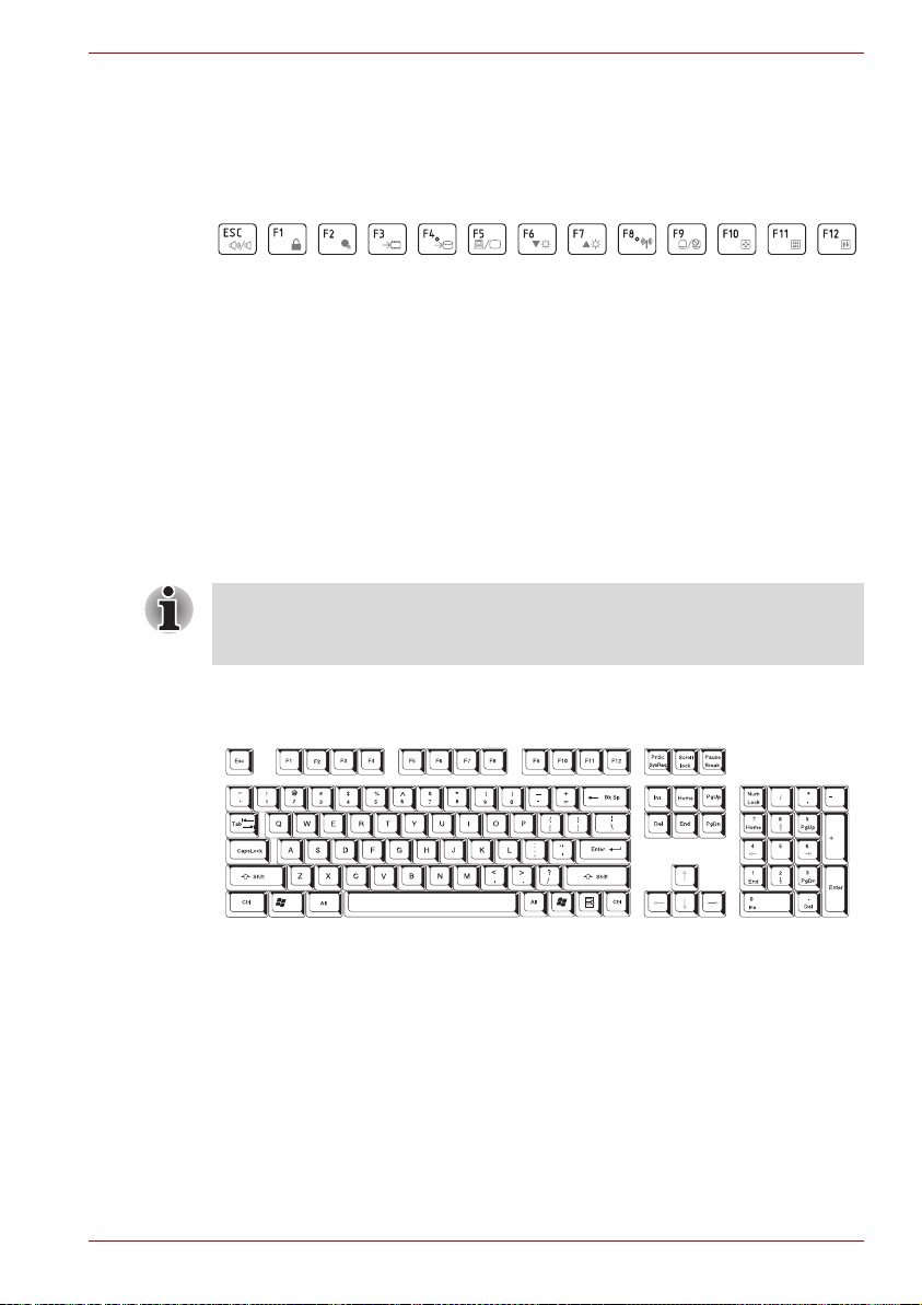
Function keys: F1 … F12
The function keys (not to be confused with the special FN key) are the
twelve keys at the top of your keyboard - these keys function differently
from other keys.
F1 through F12 are called function keys because they execute
programmed functions when pressed and, when used in combination with
the FN key, those keys marked with icons also execute specific functions
on the computer. Please refer to the section, Soft keys: FN key
combinations, in this chapter for further information, taking care to note that
the function executed by individual keys will depend on the software you
are using.
Soft keys: FN key combinations
The FN (function) is unique to TOSHIBA computers and is used in
combination with other keys to form soft keys. Soft keys are key
combinations that enable, disable or configure specific features.
Please note that some software may disable or interfere with soft-key
operations, and that the soft-key settings are not restored when the
computer returns from Sleep Mode.
The Keyboard
Emulating keys on an enhanced keyboard
Figure 5-1 A 104-key enhanced keyboard layout
This computer's keyboard is designed to provide all the features of the 104key enhanced keyboard.
Since the keyboard is smaller and has fewer keys, some of the enhanced
keyboard functions must be simulated using two keys instead of one on the
larger keyboard.
The FN key can be combined with the following keys to simulate functions
similar to those of keys on the 104/105 key enhanced keyboard which are
not on this computer's keyboard.
User’s Manual 5-2
Page 74

Hot keys
The Keyboard
Press FN + F10 or FN + F11 to access the computer's integrated keypad.
When activated, the keys with grey markings on their bottom edge become
either numeric keypad keys (FN + F11) or cursor control keys (FN + F10).
Please refer to the Keypad overlay section in this chapter for more
information on how to operate these keys, taking care to note that the
power on default for both settings is off.
Press FN + F12 (ScrLock) to lock the cursor on a specific line. The power
on default is off.
Press FN + ENTER to simulate ENTER on the enhanced keyboard’s
numeric keypad.
Hot keys (pressing FN + a function or ESC key) let you enable or disable
certain features of the computer.
Mute: Pressing FN + ESC turns the volume on and off.
Lock: Pressing FN + F1 enters ''Lock computer mode''. To restore your
desktop, you need to log on again.
Power Plan: Pressing FN + F2 changes the power settings.
User’s Manual 5-3
Page 75

The Keyboard
Sleep: Pressing FN + F3 switches the system to Sleep mode.
Hibernate: Pressing FN + F4 switches the system to Hibernation mode.
Output: Pressing FN + F5 changes the active display device.
Brightness (Down): Pressing FN + F6 decreases the computer's display
panel brightness in individual steps.
Brightness (Up): Pressing FN + F7 increases the computer's display panel
brightness in individual steps.
Wireless: Pressing FN + F8 switches the active wireless devices.
■ If no wireless communication device is installed, no dialog box will
appear.
■ This hot key is available only when the wireless communication is set
to enabled in BIOS Setup or HW Setup.
User’s Manual 5-4
Page 76

The Keyboard
Touch Pad: Pressing FN + F9 enables or disables the Touch Pad function.
Zoom: Pressing FN + Space changes the display resolution.
TOSHIBA Zooming Utility (reduce): Pressing FN + 1 reduces the icon
size on the desktop or the font sizes within one of the supported application
windows.
TOSHIBA Zooming Utility (enlarge): Pressing FN + 2 enlarges the icon
size on the desktop or the font sizes within one of the supported application
windows.
Volume down: Pressing FN + 3 to decrease the volume in increments.
Volume up: Pressing FN + 4 to increase the volume in increments.
FN Sticky key
You can use the TOSHIBA Accessibility Utility to make the FN key sticky,
that is, you can press it once, release it, and then press an "F Number"
key. To start the TOSHIBA Accessibility utility, click Start
J
TOSHIBA J Utilities J Accessibility.
User’s Manual 5-5
J
All Programs
Page 77

Windows special keys
The keyboard provides two keys that have special functions in Windows:
Windows Start Button activates the Start menu and the other, the
application key, has the same function as the secondary mouse button.
This key activates the Windows Start menu.
This key has the same function as the secondary (right) mouse button.
Keypad overlay
Your computer's keyboard does not have a separate numeric keypad but
includes a numeric keypad overlay which functions like one - this is located
in the center of the keyboard with the relevant keys having grey letters at
their front edge. The overlay provides the same functions as the numeric
keypad on a standard 104/105-key enhanced keyboard.
Turning on the overlays
The numeric keypad overlay can be used for numeric data input or cursor
and page control.
The Keyboard
Arrow mode
To turn on Arrow Mode, press FN + F10 - the Arrow mode indicator lights
and you are able to access cursor and page control functions by using the
keys. You are able to press FN + F10 again to turn off this overlay function.
Numeric mode
To turn on Numeric Mode, press FN + F11 - the Numeric Mode indicator
lights and you are able to access numeric characters by using the keys.
You are able to press FN + F11 again to turn off this overlay function.
User’s Manual 5-6
Page 78

Figure 5-2 The numeric keypad overlay
Temporarily using normal keyboard (overlay on)
While using the overlay, you can temporarily access the normal keyboard
functions without having to turn the overlay off:
1. Hold FN and press any other key - this key will operate as if the overlay
were off.
2. Type upper-case characters by holding FN + SHIFT and pressing a
character key.
3. Release FN to continue using the selected overlay function.
The Keyboard
Temporarily using overlay (overlay off)
While using the normal keyboard function, you can temporarily use the
keypad overlay without having to turn it on:
1. Press and hold down FN.
2. Check the keyboard indicators as pressing the FN key will turn on the
most recently used overlay function - if the Numeric Mode indicator
lights you can use the overlay for numeric entry, while if the Arrow Mode
indicator lights, you can use the overlay for cursor and page control
function.
3. Release FN to return to normal keyboard operation.
Temporarily changing modes
If the computer is in Numeric Mode, you can switch temporarily to Arrow
Mode by pressing a SHIFT key, while if it is in Arrow Mode, you can switch
temporarily to Numeric Mode by also pressing a SHIFT key.
User’s Manual 5-7
Page 79

Generating ASCII characters
Not all ASCII characters can be generated using normal keyboard
operation, but you are able to generate these characters using their specific
ASCII codes.
With the overlay on:
1. Hold down ALT.
2. Using the overlay keys, type the ASCII code of the character you
require.
3. Release ALT - the ASCII character will appear on the display screen.
With the overlay off:
1. Hold down ALT + FN.
2. Using the overlay keys, type the ASCII code of the character you
require.
3. Release ALT + FN - the ASCII character will appear on the display
screen.
The Keyboard
User’s Manual 5-8
Page 80

Chapter 6
Power and Power-up Modes
The computer's power resources include the AC adaptor and internal
batteries. This chapter gives details on making the most effective use of
these resources including charging and changing batteries, tips for saving
battery power, and power-up modes.
Power conditions
The computer's operating capability and battery charge status are affected
by different power conditions, including whether an AC adaptor is
connected, whether a battery pack is installed and what the charge level is
for that battery.
Table 6-1 Power conditions
Power on
AC
adaptor
connected
User’s Manual 6-1
Battery fully
charged
Battery partially
charged or no
charge
No battery
installed
• Operates
• LED: Battery green and
solid on
DC IN green
• Operates
• Charge
• LED: Battery amber and
solid on
DC IN green
• Operates
• No charge
• LED: Battery off
DC IN green
Power off
(no operation)
• LED: Battery green and
solid on
DC IN green
• Charge
• LED: Battery amber and
solid on
DC IN green
• No charge
• LED: Battery off
DC IN green
Page 81

AC
adaptor
not
connected
Battery charge
is above low
battery trigger
point
Battery charge
is below low
battery trigger
point
Battery charge
is exhausted
No battery
installed
Power indicators
Power and Power-up Modes
Table 6-1 Power conditions continued
Power on Power off
(no operation)
• Operates
• LED: Battery off
DC IN off
• Operates
• LED: Battery amber and
Computer goes into Sleep
Mode and shuts down
• Cannot operate
• LED: Battery off
blinking
DC IN off
off
DC IN
As shown in the below table, the Battery, DC IN and Power indicators on
the system indicator alert you to the computer’s operating capability and
battery charge status.
Battery indicator
Check the Battery indicator to determine the status of the battery pack the following indicator conditions should be noted:
Blinking amber
Amber
Green
No light
If the battery pack becomes too hot while it is being charged, the charge
will stop and the Battery indicator will go out. When the battery pack's
temperature falls to a normal range, charging will resume - this process will
occur regardless of whether the computer's power is on or off.
User’s Manual 6-2
The battery charge is low, the AC adaptor must
be connected in order to recharge the battery.
Indicates the AC adaptor is connected and the
battery is charging.
Indicates the AC adaptor is connected and the
battery is fully charged.
Under any other conditions, the indicator does
not light.
Page 82

Power and Power-up Modes
DC IN indicator
Check the DC IN indicator to determine the power status with the AC
adaptor connected - the following indicator conditions should be noted:
Green
No light
Power indicator
Check the Power indicator to determine the power status of the computer -
the following indicator conditions should be noted:
Green
Blinking Amber
No light
Battery types
The computer has two different types of batteries:
■ Battery pack
■ Real Time Clock (RTC) battery
Indicates the AC adaptor is connected and is
correctly supplying power to the computer.
Under any other conditions, the indicator does not
light.
Indicates power is being supplied to the computer
and the computer is turned on.
Indicates that the computer is in Sleep Mode and
that there is sufficient power available (AC
adaptor or battery) to maintain this condition. In
Sleep Mode, this indicator will turn on for two
seconds and off for one second.
Under any other conditions, the indicator does
not light.
Battery pack
When the AC adaptor is not connected, the computer's main power source
is a removable lithium ion battery pack, also referred to in this manual as
the battery. You can purchase additional battery packs for extended use of
the computer away from an AC power source although you should not
change the battery pack while the AC adaptor is connected.
Before you remove the battery pack, save your data and shut down the
computer, or place the computer into Hibernation Mode. Please be aware
that, when placing the computer into Hibernation Mode, the contents of
memory will be saved to the hard disk drive, although for safety sake, it is
best to also save your data manually.
User’s Manual 6-3
Page 83

Power and Power-up Modes
■ The battery pack is a lithium ion battery, which can explode if not
properly replaced, used, handled or disposed of. Dispose of the battery
as required by local ordinances or regulations. Use only batteries
recommended by TOSHIBA as replacements.
■ Do not remove the battery pack while the computer is in Sleep Mode. In
this mode data is stored in memory, so if the computer loses power, it
will be lost.
■ Battery type (depending on the model you purchased)
Real Time Clock battery
The Real Time Clock (RTC) battery provides power for the internal real
time clock and calendar function and also maintains the system
configuration while the computer is turned off. If the RTC battery becomes
completely discharged, the system will lose this information and the real
time clock and calendar will stop working - in this instance the following
message will be displayed when you turn on the power:
ERROR 0271: Check date and time settings.
S
The computer's RTC battery is a lithium battery and should be replaced
only by your dealer or by a TOSHIBA service representative. The battery
can explode if not properly replaced, used, handled or disposed of.
Dispose of the battery as required by local ordinances or regulations.
WARNING 0251: System CMOS checksum bad - Default
configuration used.
Press <F1> to resume, <F2> to Setup.
When this error appears, the following action is recommended.
1. Connect the AC adaptor and let the battery charge for 24-hours.
2. Press F2 to enter BIOS setup menu.
3. Set correct time and date.
If you still see the error message after performing the above actions,
please contact your TOSHIBA service representative.
User’s Manual 6-4
Page 84

Care and use of the battery pack
The battery pack is a vital component of portable computing and, as such,
taking proper care of it will help ensure a longer operating time on battery
power as well as deliver a longer life for your battery pack. The instructions
detailed in this section will help to ensure safe operation and maximum
performance.
Refer to the enclosed Instruction Manual for Safety and Comfort for
detailed precautions and handling instructions.
■ Make sure the battery is securely installed in the computer before
attempting to charge the battery pack. Improper installation could
generate smoke or fire, or cause the battery pack to rupture.
■ Keep the battery pack out of reach of infants and children. It can cause
injury.
■ The battery pack is lithium ion battery, which can explode if not
replaced, used, handled or disposed of properly. Dispose of the battery
as required by local ordinances or regulations. Use only batteries
recommended by TOSHIBA as replacements.
■ Charge the battery pack only in an ambient temperature between 5 and
35 degrees Celsius. Otherwise, the electrolyte solution might leak,
battery pack performance might deteriorate and the battery life might
be shortened.
■ Never install or remove the battery pack without first turning off the
power and disconnecting the AC adaptor. Never remove the battery
pack while the computer is in Sleep Mode. Data will be lost.
Power and Power-up Modes
■ Never remove the battery pack while the Wake-up on LAN function is
enabled. Data will be lost. Before you remove a battery pack, disable
the Wake-up on LAN function.
Charging the batteries
When the power in the battery pack becomes low, the Battery indicator will
flash amber to indicate that only a few minutes of battery power remain. If
you continue to use the computer while the Battery indicator flashes, the
computer will enable Hibernation Mode so that you do not lose any data,
and automatically turn itself off.
You must recharge a battery pack when it becomes discharged.
Procedures
To recharge a battery pack while it is installed in the computer, connect the
AC adaptor to the DC IN 19V jack and plug the other end into a working
outlet - the Battery indicator will glow amber while the battery is being
charged.
User’s Manual 6-5
Page 85

Power and Power-up Modes
Use only the computer connected to an AC power source to charge the
battery pack. Never attempt to charge the battery pack with any other
charger.
Time
The following table shows the approximate time required to fully charge a
discharged battery.
Charging time (hours)
Battery type Power on Power off
Battery Pack
(3 cell)
Battery Pack
(6 cell)
RTC battery about 24 about 24 with AC or
Please be aware that the charging time when the computer is on is
affected by ambient temperature, the temperature of the computer and
how you are using the computer - if you make heavy use of external
devices for example, the battery might scarcely charge at all during
operation. Please refer to the section Maximizing battery operating time for
further information.
about 12 or longer about 4 or longer
about 12 or longer about 6 or longer
Battery pack
Battery charging notice
The battery may not begin charging immediately under the following
conditions:
■ The battery is extremely hot or cold (if the battery is extremely hot, it
might not charge at all). To ensure the battery charges to its full capacity,
you should charge it at room temperature of between 5° to 35°C (41° to
95°F).
■ The battery is nearly completely discharged. In this instance you should
leave the AC adaptor connected for a few minutes and the battery
should begin charging.
The Battery indicator may show a rapid decrease in battery operating time
when you try to charge a battery under the following conditions:
■ The battery has not been used for a long time.
■ The battery has completely discharged and been left in the computer for
a long time.
■ A cool battery is installed in a warm computer.
User’s Manual 6-6
Page 86

Power and Power-up Modes
In such cases you should follow the steps as detailed below:
1. Fully discharge the battery by leaving it in the computer with the power
on until the system automatically turns itself off.
2. Connect the AC adaptor to the DC IN 19V jack of the computer, and to
a wall outlet that is supplying power.
3. Charge the battery until the Battery indicator glows green.
Repeat these steps two or three times until the battery recovers normal
capacity.
Monitoring battery capacity
Remaining battery power can be monitored in Power Options.
■ You should wait at least 16 seconds after turning on the computer
before trying to monitor the remaining operating time. This is because
the computer needs this time to check the battery's remaining capacity
and then calculate the remaining operating time, based on this together
with the current power consumption.
■ Please be aware that the actual remaining operating time may differ
slightly from the calculated time.
■ With repeated discharges and recharges, the battery's capacity will
gradually decrease. In view of this it will be noted that an often used,
older battery will not operate for as long as a new battery even when
both are fully charged.
Maximizing battery operating time
A battery's usefulness depends on how long it can supply power on a
single charge, while how long the charge lasts in a battery depends on:
■ Processor speed
■ Screen brightness
■ System Sleep Mode
■ System Hibernation Mode
■ Display power off period
■ Hard disk drive power off period
■ How often and for how long you use the hard disk drive, optical disc and
floppy diskette drives.
■ How much charge the battery contained to begin with.
■ How you use optional devices, such as a USB device, to which the
battery supplies power.
■ Whether you enable Sleep Mode, which can conserve battery power if
you are frequently turning the computer off and on.
■ Where you store your programs and data.
■ Whether you close the display panel when you are not using the
keyboard - closing the display saves power.
User’s Manual 6-7
Page 87

Power and Power-up Modes
■ The environmental temperature - operating time decreases at low
temperatures.
■ The condition of the battery terminals - you should always ensure the
terminals stay clean by wiping them with a clean dry cloth before
installing the battery pack.
Retaining data with power off
When you turn off your computer with fully charged batteries, the batteries
retain data for the following approximate time periods.
Retention Time
Battery type State and Retention Time
Battery pack 1 day for 6 cell, 0.5 day for 3 cell
RTC battery 30 days
(Sleep mode)
30 days for 3 cell, 60 days for 6 cell
(shut down mode)
Extending battery life
To maximize the life of your battery packs:
■ At least once a month, disconnect the computer from a power source
and operate it on battery power until the battery pack fully discharges.
Before doing so, follow the steps as detailed below.
1. Turn off the computer's power.
2. Disconnect the AC adaptor and turn on the computer's power - if it
does not turn on then go to Step 4.
3. Operate the computer on battery power for five minutes. If you find
that the battery pack has at least five minutes of operating time,
continue operating until the battery pack is fully discharged,
however, if the Battery indicator flashes or there is some other
warning to indicate a low battery condition, go to Step 4.
4. Connect the AC adaptor to the DC IN 19V jack of the computer, and
to a wall outlet that is supplying power. The DC IN indicator should
glow green, and the Battery indicator should glow amber to indicate
that the battery pack is being charged, however, in the event that
DC IN indicator does not glow this indicates that power is not being
supplied - check the connections for the AC adaptor and the power
cord.
5. Charge the battery pack until the Battery indicator glows green.
■ If you have extra battery packs, rotate their use.
■ If you will not be using the system for an extended period, for example
for more than one month, remove the battery pack from the computer.
User’s Manual 6-8
Page 88

■ Disconnect the AC adaptor when the battery is fully charged -
overcharging will make the battery hot and can shorten its operating life.
■ If you are not going to use the computer for more than eight hours,
disconnect the AC adaptor.
■ Store spare battery packs in a cool dry place out of direct sunlight.
Replacing the battery pack
Please be aware that the battery pack is classified as a consumable item.
The operating life of the battery pack will gradually reduce through
repeated charging and discharging, and will need to be replaced when it
reaches the end of its operating life. In addition to this, you might also
replace a discharged battery pack with a charged spare when you are
operating your computer away from an AC power source for an extended
period of time.
This section explains how to remove and install the battery pack, and
begins with the removal process which is detailed through the following
steps.
■ Do not remove the battery pack while the computer is in Sleep Mode.
Data is stored in RAM, so if the computer loses power it will be lost.
■ In Hibernation Mode, data will be lost if you remove the battery pack or
disconnect the AC adaptor before the save is completed. Wait for the
Hard Disk Drive indicator to go out.
■ Do not touch the battery release latch while holding the computer or the
battery pack might fall out due to the unintentional release of the
battery release latch and cause injuries.
Power and Power-up Modes
To remove a discharged battery, follow the steps as detailed below:
1. Save your work.
2. Turn the computer's power off - ensure that the Power indicator is off.
3. Remove all cables and peripherals that are connected to the computer.
4. Close the display panel and turn the computer upside down.
User’s Manual 6-9
Page 89

Power and Power-up Modes
5. Slide the battery safety lock towards the release ( ) position to make
the battery release latch movable.
1
1. Battery safety lock
2. Battery release latch
3. Battery pack
Figure 6-1 Releasing the battery pack (1)
6. Slide and hold the battery release latch (1) to disengage the battery
pack and then remove it from the computer (2).
3
2
1
Figure 6-2 Releasing the battery pack (2)
User’s Manual 6-10
Page 90

Power and Power-up Modes
To install a battery, follow the steps as detailed below:
1. Insert the battery pack as far as it will go into the computer (1).
2. Ensure that the battery pack is securely in place and the battery safety
lock (2) is in its position.
2
1. Battery Pack
2. Battery safety lock
Figure 6-3 Securing the battery pack
3. Turn your computer over.
1
User’s Manual 6-11
Page 91

TOSHIBA Password Utility
The TOSHIBA Supervisor Password Utility allows you to maintain an
additional level of security and provides two levels of password security:
User and Supervisor.
Power and Power-up Modes
Passwords set in TOSHIBA Supervisor Password Utility are different from
the Windows
®
login password.
User Password
To start the utility, point to or click the following items:
Launch TOSHIBA Assist J SECURE J User Password
■ Registered
Click to register a password of up to 8 characters. After a password is
set, you will be prompted to enter it when you start the computer.
■ Not Registered
Click to delete a registered password. Before you can delete a
password, you must first enter the current password correctly.
■ Owner String (text box)
You can use this box to associate text with the password. After you
enter text, click Apply or OK, then, each time the computer is switched
on, this text will be displayed along with the prompt for the password.
Supervisor password
If you set a supervisor password, some functions will be restricted when a
user logs on with the user password. To set a supervisor password:
TOSHIBA Assist J SECURE J Supervisor password
This utility lets you do the following:
■ Register or delete the supervisor password.
■ Specify restrictions for general users.
Starting the computer by password
If you have already registered a password, there is one way to start the
computer:
■ Enter the password manually.
The password is necessary if the computer was shut down in boot mode
and Hibernation mode, not in Sleep mode.
To enter a password manually, follow these steps:
1. Turn on the power as described in Chapter 3, Getting Started. The
following message will appear in the LCD:
Enter Password [xxxxxxxx]
2. Enter the Password.
3. Press Enter.
User’s Manual 6-12
Page 92

If you enter the password incorrectly three consecutive times, the
computer shuts down. You must turn on the computer again and re-enter
the password.
Power-up modes
The computer has three power-up modes:
■ Boot: Computer shuts down without saving data. Always save your
work before you turn the computer off in boot mode.
■ Hibernation: Data in memory is saved to the hard disk.
■ Sleep: Data is maintained in the computer’s main memory.
Refer also to the section Turning off the power in Chapter 3, Getting
Started.
Windows utilities
You can configure various settings associated with both Sleep Mode and
Hibernation Mode within the Power Options. To access it, Start
Panel
J
System and Security J Power Options.
Hot keys
You can use the FN + F3 hot key to enter Sleep Mode or FN + F4 to enter
Hibernation Mode - please refer to Chapter 5, The Keyboard for further
details.
Power and Power-up Modes
J
Control
Panel power on/off
You can set up your computer so that power is turned off automatically
when you close the display panel, and turned on again when you open it.
Please note that this function is only available for Sleep Mode or
Hibernation Mode, not for Boot Mode.
If the panel power off function is enabled, and you manually shut down
Windows, do not close the computer's display panel until the shut down
process has been completed.
System auto off
This feature turns the system off automatically if it is not used for a set
duration. The system shuts down in Sleep Mode or Hibernation Mode.
User’s Manual 6-13
Page 93

HW Setup and Passwords
This chapter explains how to use TOSHIBA HW Setup program to
configure your computer and how to set passwords.
HW Setup
TOSHIBA HW Setup allows you to configure settings for General,
Password, Display, Boot Priority, Keyboard, USB, LAN.
If the supervisor password is set, access to the TOSHIBA HW Setup
program can be prevented when the user password is used to log on to the
computer.
Accessing HW Setup
Click on Start → All Programs → TOSHIBA → Utilities and click
HWSetup.
Chapter 7
HW Setup Window
The HW Setup window contains the following tabs: General, Password,
Display, Boot Priority, Keyboard, LAN, USB.
OK Accepts your changes and closes the HW Setup
Cancel Closes the window without accepting your
Apply Accepts all your changes without closing the HW
General
User’s Manual 7-1
window.
changes.
Setup window.
Page 94

HW Setup and Passwords
This window displays the BIOS version and contains two buttons:
Default Return all HW Setup values to the factory
About Display the HW Setup version.
settings.
Setup
This field displays BIOS Version and date.
When finish BIOS update, please restart your computer and press F2 into
BIOS setup manual and load BIOS default one time.
Password
User Password
This option allows you to set or reset the user password for power on.
Not Registered Changes or remove the password. (Default)
Registered Sets the password. A dialogue box will appear to
To enter a user password:
1. Select Registered to display the following prompt:
Enter Password:
Enter a password of up to 8 characters. The character string you enter
is displayed as a string of asterisks. For example, if you enter a
password consisting of four characters, the display is shown as:
Enter Password: ****
2. Click the OK button. The following message appears, allowing you to
verify the password.
Verify Password:
3. If character strings match, the password is registered click OK button. If
they do not match, the following message appears. You must repeat
from step 1.
Entry Error!!!
To delete a user password:
1. Select Not Registered to display the following prompt:
Enter Password:
2. Enter the currently registered password. The character string you enter
is displayed as a string of asterisks.
Enter Password: ****
3. Click the OK button. If the character string you enter matches the
registered password, the password option is reset and the display
changes to:
Not registered
allow you to set the password.
User’s Manual 7-2
Page 95

HW Setup and Passwords
If they do not match, the following message appears. You must repeat step 1.
Incorrect Password!!!
If you enter the password incorrectly three times in a row, the computer will
shut down.
You will not be able to access the password option in the HW Setup. In this
case you must turn the power off and back on to retry the procedure.
4. Follow the same procedures described in the earlier section to set a
new user password.
Display
This tab allows you to customize your computer’s display settings for either
the internal LCD screen or for an external monitor.
Power On Display
Allows you to set the display to be used when the computer is booted.
Auto-Selected If any external display is connected, the power on
display will be in external display only mode.
Otherwise it will be in LCD only mode.
System LCD only Irrespective of external display connection, the
power on display will be in integrated LCD only
mode.
Boot Priority
Boot Priority Options
This option sets the priority for booting the computer. Select the boot
priority from the drop down list.
Keyboard
Wake-up on Keyboard
When this feature is enabled and the computer is in Sleep mode, you can
turn on the computer by pressing any key. It is effective only for the internal
keyboard and only when the computer is in Sleep mode.
Enabled Enables the Wake-up on Keyboard feature.
Disabled Disables the Wake-up on Keyboard function
(Default).
USB
Legacy USB Support
Use this option to enable or disable USB Legacy Emulation. If your
operating system does not support USB, you can still use a USB mouse
and keyboard by setting the USB Legacy Emulation item to enabled.
User’s Manual 7-3
Page 96
HW Setup and Passwords
Enabled Enables the USB Legacy Emulation. (Default)
Disabled Disables the USB Legacy Emulation.
LAN
Wake-up on LAN
This feature lets the computer’s power be turned on from shutdown when it
receives awake-up packet ( Magic packet ) from the LAN.
Regarding Wake-up on LAN from sleep or hibernation, you must check the
"Allow the device to wake the computer" check box within the LAN Device
properties. ( This feafure does not affect the Wake-up on LAN from sleep or
hibernation. )
Enabled Enables Wake-up on LAN from shutdown.
Disabled Disables Wake-up on LAN. from shutdown.
(Default)
The Wake-up on LAN function consumes power even when the system is
off. Leave the AC adaptor connected while using this feature.
Do not install or remove an optional memory module while Wake-up on
LAN is enabled.
Built-in LAN
This feature enables or disables the Built-in LAN.
Enabled Enables Built-in LAN function (Default).
Disabled Disables Built-in LAN function.
Wireless Communication Switch
This feature enables or disables the Wireless Communication Switch.
On Enable Wireless Communication Switch function.
Off Disable Wireless Communication Switch
function.
To access BIOS setup menu, press F2 when booting up the computer.
User’s Manual 7-4
Page 97

Optional Devices
Optional devices can expand the computer's capabilities and its versatility.
This chapter describes the connection or installation of the following
devices:
To connect optional devices (such as USB device or External monitor) to
the computer, be sure to check the shape and orientation of the connector
before connecting.
Cards/memory
■ Bridge media slot
■ Secure Digital
miniSD Card, microSD Card)
■ MultiMediaCard
■ Additional memory module
Power devices
■ Battery packs
■ Universal AC Adaptor
TM
(SD) Card (SD memory card, SDHC memory card,
Chapter 8
Peripheral devices
■ USB floppy diskette drive
■ USB optical disc drive
■ External monitor
Other
■ Security lock
User’s Manual 8-1
Page 98
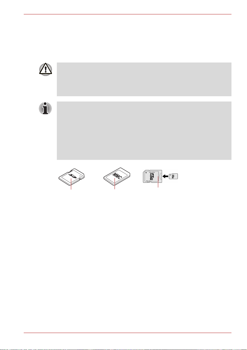
Bridge media slot
The computer is equipped with a Bridge media slot that can accommodate
some kinds of memory media with various memory capacities so that you
can easily transfer data from devices, such as digital cameras and
Personal Digital Assistants.
■ Keep foreign objects out of the Bridge media slot. Never allow metal
objects, such as screws, staples and paper clips, to enter the computer
or Keyboard. Foreign metal objects can create a short circuit, which
can cause computer damage and fire, possibly resulting in serious
injury.
■ This Bridge media slot supports the following memory media.
■ Secure Digital (SD) Card (SD memory card, SDHC memory card,
miniSD Card, microSD Card).
■ MultiMediaCard (MMC)
■ To use a micro or mini SD card, an SD adaptor is required.
■ Please note that not all memory media have been tested and verified to
work correctly. Therefore, it is not possible to guarantee that all
memory media will operate properly.
Optional Devices
Secure Digital
(SD) Card
MultiMediaCard
(MMC)
Figure 8-1 Examples of memory media
microSD card
and adaptor
Memory media
This section provides the important safety precautions in order to handle
your memory media.
Points to note about the SD/SDHC memory card
SD/SDHC memory cards comply with SDMI (Secure Digital Music
Initiative), which is a technology adopted to prevent unlawful copy or
playback of digital music. For this reason, you cannot copy or playback
protected material on another computer or other device, and you may not
reproduce any copyrighted material except for your personal enjoyment.
Below is a simple explanation for distinguishing SD memory cards from
SDHC memory cards.
■ SD and SDHC memory cards appear the same externally.
■ The logo on SD and SDHC memory cards is different, so pay careful
attention to the logo when purchasing.
User’s Manual 8-2
Page 99

Optional Devices
■ The SD memory card logo is ( ).
■ The SDHC memory card logo is ( ).
■ The maximum capacity of SD memory cards is 2GB. The maximum
capacity of SDHC memory cards is 32GB.
Card Type Capacities
SD 8MB, 16MB, 32MB, 64MB, 128MB, 256MB,
SDHC 4GB, 8GB, 16GB, 32GB
512MB, 1GB, 2GB
Memory media format
New media cards are formatted according to specific standards. If you wish
to reformat a media card, be sure to do so with a device that uses media
cards.
Formatting an SD/SDHC memory card
SD/SDHC memory cards are sold already formatted in conformity to
specific standards. If you reformat an SD/SDHC memory card, be sure to
reformat it with a device such as digital camera or digital audio player that
uses the SD/SDHC memory cards, not with the format command provided
within Windows.
Should you need to format all areas of the memory card, including the
protected area, you will need to obtain an appropriate application that
applies the copy protection system.
User’s Manual 8-3
Page 100

Additional memory module
You can replace with an additional memory in order to increase the amount
of system memory that is available.
This section describes how to install and remove optional memory
modules.
■ You should place a mat beneath the computer in order to prevent the
computer's lid from becoming scratched or damaged when you are
installing/replacing the memory module. In this instance you should
avoid mats that are made of materials that hold or generate static
electricity.
■ When installing or removing a memory module, you must ensure that
you do not touch any other internal areas of the computer.
■ Use only memory modules approved by TOSHIBA.
■ Do not try to install or remove a memory module under the following
conditions.
a. The computer is turned on.
b. The computer was shut down in either Sleep or Hibernation Mode.
c. Wake-up on LAN is enabled.
d. The wireless communication is enabled.
e. USB Sleep and Charge function is enabled.
■ Be careful not to let screws or other foreign matter fall into the
computer. It could cause malfunction or electric shock.
■ Additional memory modules are precision electronic components that
may be fatally damaged by static electricity. Since the human body can
carry static electricity, it is important that you discharge yourself before
touching or installing any additional memory modules. To discharge
your body’s static electricity, simply touch any metal close to you with
bare hands.
■ Turn off the power and disconnect the AC adaptor when installing or
replacing a memory module.
■ If you use the computer for an extended period of time, the memory
modules and the circuits located close to the memory modules will
become hot. Allow then to cool to room temperature before you replace
them.
Optional Devices
Installing a memory module
To install a memory module:
1. Shut down the computer - make sure the Power indicator is off (refer to
the Turning off the power section in Chapter 3, Getting Started if
required).
2. Remove the AC adaptor and all cables and peripherals connected to
the computer.
User’s Manual 8-4
 Loading...