

Page 1

STACK FEED BYPASS
MY-1016
File No. 31100017
Page 2

General Precautions for Installation/Servicing/Maintenance for the MY-1016
The installation and service should be done by a qualified service technician.
1. When installing the MY-1016 to the Plain Paper Copier, be sure to follow the instructions described in
the “Unpacking/Set-Up Procedure for the MY-1016” booklet which comes with each unit of the
MY-1016.
2. The MY-1016 should be installed by an authorized/qualified person.
3. Before starting installation, servicing or maintenance work, be sure to turn off and unplug the copier
first.
4. When servcing or maintaining the MY-1016, be careful about the rotating or operation sections such
as gear, pulleys, sprockets, cams, belts, etc.
5. When parts are disassembled, reassembly is basically the reverse of disassembly unless otherwise
noted in this manual or other related materials. Be careful not to reassemble small parts such as
screws, washers, pins, E-rings, toothed washers to the wrong places.
6. Basically, the machine should not be operated with any parts removed or disassembled.
7. Delicate parts for preventing safety hazard problems (such as breakers, thermofuses, fuses, door
switches, sensors, etc. if any) should be handled/installed/adjusted correctly.
8. Use suitable measuring instruments and tools.
9. During servicing or maintenance work, be sure to check the serial No. plate and other cautionary
labels (if any) to see if they are clean and firmly fixed. If not, take appropriate actions.
10. The PC board must be stored in an anti-electrostatic bag and handled carefully using a wristband,
because the ICs on it may be damaged due to static electricity. Before using the wrist band, pull out
the power cord plug of the copier and make sure that there is no uninsulated charged objects in the
vicinity.
11. For the recovery and disposal of used MY-1016, consumable parts and packing materials, it is rec-
ommended that the relevant local regulations/rules should be followed.
12. After completing installation, servicing and maintenance of the MY-1016, return the MY-1016 to its
original state, and check operation.
Copyright 2000
TOSHIBA TEC CORPORATION
Page 3

CONTENTS
1. SPECIFICATIONS ...................................................................................................... 1-1
2. OUTLINE .................................................................................................................... 2-1
2.1 Names of Various Components ......................................................................................... 2-1
2.2 Layout of Electrical Parts .................................................................................................. 2-2
2.3 Harness Connection Diagram ............................................................................................ 2-3
3. OPERATIONAL DESCRIPTION ................................................................................ 3-1
3.1 General Operation ............................................................................................................. 3-1
3.2 Block Diagram .................................................................................................................. 3-1
3.3 Detection of Abnormal Status ........................................................................................... 3-2
3.3.1 Paper jam detection ............................................................................................... 3-2
3.4 Flow Charts ...................................................................................................................... 3-3
4. MECHANICAL DESCRIPTION .................................................................................. 4-1
4.1 Paper Feed System .......................................................................................................... 4-1
4.2 Drive System .................................................................................................................... 4-2
5. CIRCUIT DESCRIPTION ........................................................................................... 5-1
5.1 Meaning of Signals ...........................................................................................................5-1
5.2 Timing Chart ..................................................................................................................... 5-2
6. DISASSEMBLY AND REPLACEMENT ..................................................................... 6-1
October 2000 © TOSHIBA TEC 1 MY-1016 CONTENTS
Page 4

1. SPECIFICATIONS
Function : Pickup roller drop and paper feed roller method
Paper : Continuous feed64 to 80g/m2 (17 to 21 lbs)
: Single sheet feed 80 to 163g/m2 (21 to 43 lbs)
Transport speed : 260 mm/sec.
Max. capacity : 11 mm (100 sheets)
Dimensions : 120 (W) x 485 (D) x 227 (H) mm
Weight : Approx. 2.5 kg
Power supply : 5VDC, 24VDC (Supplied from copier)
October 2000 © TOSHIBA TEC 1 - 1 MY-1016 SPECIFICATIONS
Page 5
2. OUTLINE
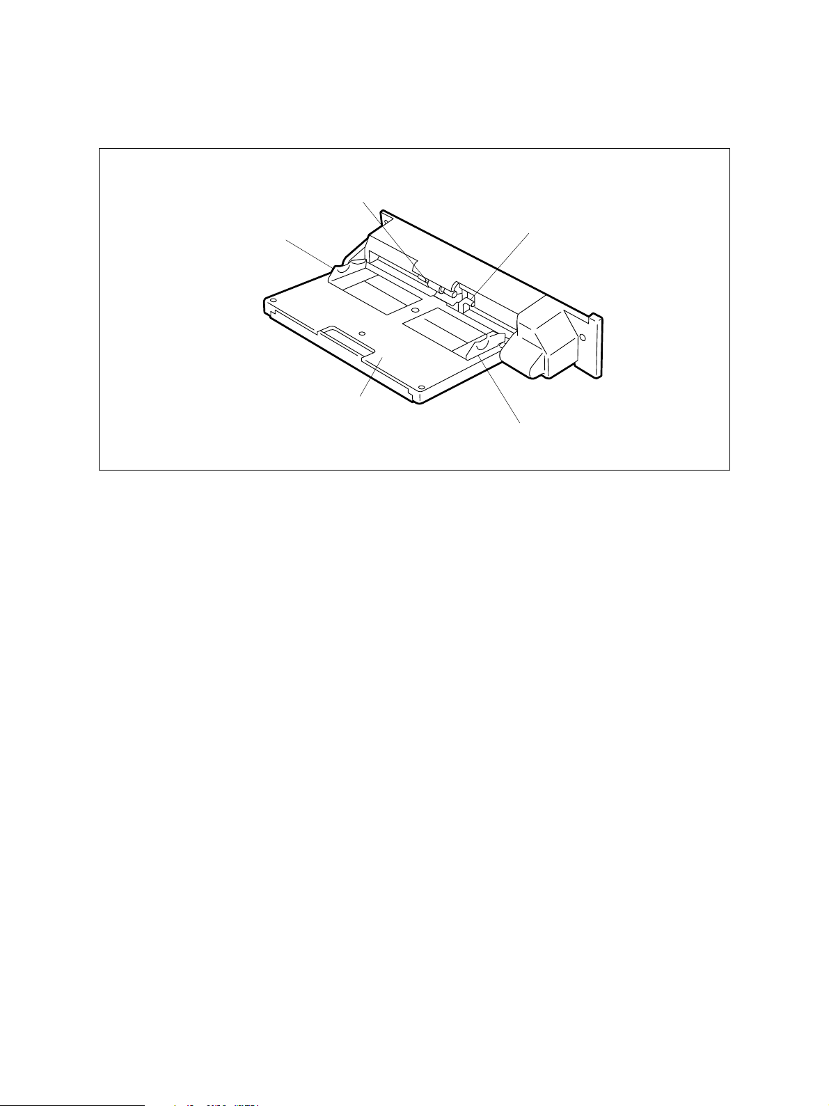
2.1 Names of Various Components
SFB pickup roller
SFB document guide F
SFB document tray
SFB feed sensor (Arm)
SFB document guide R
SFB 02-01-01
October 2000 © TOSHIBA TEC 2 - 1 MY-1016 OUTLINE
Page 6
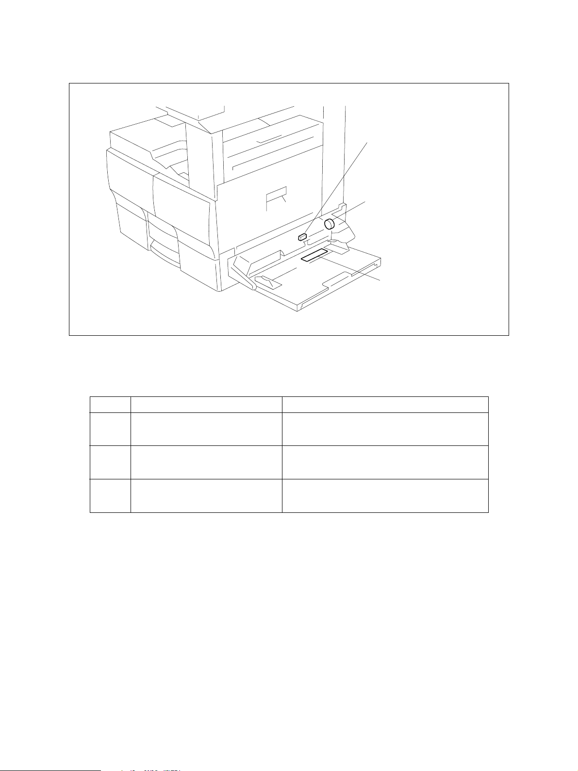
2.2 Layout of Electrical Parts
SEN1
CL1
PSS
SFB 02-02-01
Symbols and functions of various devices
Symbol
SEN1
SET-SEN
Name
SFB feed sensor
CL1
MPU-CLT
SFB clutch
PSS
PSS-PWA
SFB paper size sensor
Function
Detects the loading of paper.
Transmits driving force to the rollers to pick up
and transport the paper.
Paper size detection.
MY-1016 OUTLINE 2 - 2 October 2000 © TOSHIBA TEC
Page 7
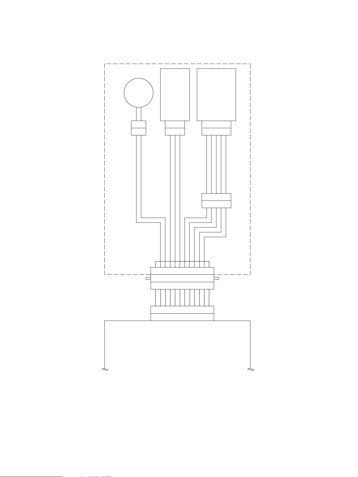
2.3 Harness Connection Diagram
SFB clutch
SFB feed sensor
SFB paper size sensor
SFB
CN303
2
1
CN304
321
CN302
123456789
987654321
121110
5
CN300
12345
54321
CN301
101112
4
321
123456789
2
4
6
SG 1
SG
CN31
MPFCON1
+5V
24VSW 3
MPESON 5
MPSS3ON 78MPSS1ON 9
10
10MPSS0ON
MPSS2ON
11
12
12MCONECT
SG 11
Relay PWA
SFB 02-03-01
October 2000 © TOSHIBA TEC 2 - 3 MY-1016 OUTLINE
Page 8

3. OPERATIONAL DESCRIPTION
3.1 General Operation
The SFB is a bypass feed unit mounted on the right side of the copier. This unit has no PWA and the
operation and detection signals are sent to the MAIN PWA through the RELAY PWA. The unit is con-
trolled by the MAIN PWA.
3.2 Block Diagram
SFB
Relay PWA
CN31
MPES
MPFCON
SSIZE0-3
SFB feed sensor
SFB clutch
SFB paper size sensor
SFB 03-02-01
The SFB consists of the one switch, one magnetic clutch, and paper size sensor. These signals connect
to the MAIN PWA through the relay cable and RELAY PWA. When the bypass feed is selected on the
copier side and paper is placed in the SFB, printing by the bypass feed is enabled.
October 2000 © TOSHIBA TEC 3 - 1 MY-1016 OPERATIONAL DESCRIPTION
Page 9

3.3 Detection of Abnormal Status
3.3.1 Paper jam detection
The SFB has the SFB feed sensor to detect that the paper has been placed. When you press the Start
key on the copier after this sensor detects the presence of paper, the SFB clutch turns ON to start
feeding. If the paper has not reached the feed sensor on the copier side for a fixed time after feeding
begins, the program will judge it to be paper jamming and stop feeding. To reset the error state, once
remove the paper and turn the SFB feed sensor OFF.
MY-1016 OPERATIONAL DESCRIPTION 3 - 2 October 2000 © TOSHIBA TEC
Page 10

3.4 Flow Charts
Start button ON
Main motor ON
Polygon motor ON
Process unit fan motor high speed rotation
Development bias ON
Separation bias ON
Charge bias ON
Discharge lamp ON
Process system control Optical system control
Transfer system control
Retraction of carriage
Polygon motor
OK?
YES
Laser ON
Transfer bias ON
NO
Service call
"CA1"
Main motor
OK?
YES
SFB clutch ON
SFB feed sensor
NO
Service call
"C01"
NG
Black shading
Exposure lamp ON
Stop of carriage
check
Transfer guide bias ON
Laser OFF
OK
SFB clutch OFF
Paper jam
"E12"
Advance of carriage
White shading
Registration roller
Transfer bias OFF
Transfer guide bias OFF
clutch ON
Registration roller
Scanning of document
Stop of carriage
clutch OFF
Exposure lamp OFF
Retraction of carriage
Stop of carriage
NO
HSYNC
OK
YES
Remaining
copy count 0?
NO
Service call
"CA2"
NO
Remaining
copy count 0?
YES
Exit sensor
NG
check 1
YES
Polygon motor OFF
End of process
system control
OK
Exit sensor
check 2
OK
Paper jam
"E01"
NG
Paper jam
"E02"
End of optical
system control
A
October 2000 © TOSHIBA TEC 3 - 3 MY-1016 OPERATIONAL DESCRIPTION
Page 11

A
Charge bias OFF
Main motor OFF
Development bias OFF
Separation bias OFF
Discharge lamp OFF
Process unit fan motor low speed rotation
Standby
MY-1016 OPERATIONAL DESCRIPTION 3 - 4 October 2000 © TOSHIBA TEC
Page 12

4. MECHANICAL DESCRIPTION
4.1 Paper Feed System
Flow of paper
SFB feed sensor
SFB pickup roller
SFB 04-01-01
Paper Pickup Operation
When you place the paper, the arm of the SFB feed sensor is pushed in causing the sensor to turn
ON (paper present). When you press the Start button on the copier to turn the gear on the copier
side, the gear of the SFB also turns and the SFB clutch turns ON, causing the SFB pickup roller to
lower and pull in the paper.
October 2000 © TOSHIBA TEC 4 - 1 MY-1016 MECHANICAL DESCRIPTION
Page 13

4.2 Drive System
Flow of paper
SFB clutch
SFB 04-02-01
The SFB is driven from the copier through the gear. When the SFB clutch turns ON, the rotation on the
copier side is transmitted to the SFB feed roller. The SFB pickup roller is connected to the SFB feed roller
through the belt. When the SFB feed roller turns, the SFB pickup roller lowers and starts picking up.
When the paper is pulled in, the SFB clutch turns OFF and the SFB pickup roller returns to its original
position.
MY-1016 MECHANICAL DESCRIPTION 4 - 2 October 2000 © TOSHIBA TEC
Page 14

5. CIRCUIT DESCRIPTION
5.1 Meaning of Signals
Signal name Part name Functional description Status Note
MPESON SFB feed sensor Detects the loading of paper Photo sensor
MPFCON SFB clutch Transmits driving force to Low: ON Magnetic
the rollers to pick up and clutch
transport the paper
MPSS 0-3 ON SFB paper size Paper size detection Low: Detection PWA pattern
sensor
The SFB feed sensor is a photo sensor which detects that the paper has been placed in the bypass tray.
The signal is usually at “High” level (no paper present) and goes LOW when the paper is placed. This
signal is sent to the MAIN PWA through the relay cable and RELAY PWA.
SFB clutch is an operation signal for the clutch to transmit driving from the copier to the SFB. The signal
output from IC36 (MFPCON) on the MAIN PWA connects to the transistor (Q16) on the RELAY PWA.
When the signal is at “High” level, Q16 turns ON to drive the clutch, causing the pickup roller to lower and
pull in the paper.
The SFB paper size sensor detects the width of the paper placed in the tray of the SFB. The brush
attached to the paper width guide is touching the pattern on the PWA, and one of the MPSS0 - 3 signals
is detected according to the position to which the paper width guide is slid. MPSS0 goes LOW at the
narrowest position, and MPSS3 at the widest position. (When each width sensor is at “Low” level, that
width is detected.) Since the detection areas overlap as shown below, two signals may be detected at
the same time depending on the position of the paper width guide
A4 Series LT Series MPSS 0 MPSS 1 MPSS 2 MPSS 3
A4 LT H H H L
A4-R LT-R H H L H
A5-R ST-R H L H H
A6 - L L H H
B4 COMP H H L L
B5-R - H L L H
B6 - L L H H
October 2000 © TOSHIBA TEC 5 - 1 MY-1016 CIRCUIT DESCRIPTION
Page 15

5.2 Timing Chart
2.65s
1.84s
610ms
The values are data (reference values) applicable when the A4 size paper is used.
SFB clutch
MY-1016 CIRCUIT DESCRIPTION 5 - 2 October 2000 © TOSHIBA TEC
SFB feed sensor
Feed sensor
SFB 05-02-01
Page 16

6. DISASSEMBLY AND REPLACEMENT
[A] SFB assembly/SFB cover
1. Remove 2 screws and detach SFB cover.
SFB cover
2. Remove one screw and detach harness fixing
plate.
3. Detach one connector, remove one screw, and
detach the ground wire.
4. Remove 2 screws, release 2 hooks, and remove
SFB assembly.
Screw
Ground wire
Screw
SFB assembly
Fig. 6-1
Screw
Fig. 6-2
245-1
Connector
Harness
fixing plate
245-2
Screw
Hook
Fig. 6-3
246
[B] SFB hinge unit
1. Remove SFB cover. (See Fig. 6-1)
2. Release one clamp and detach the harness.
Harness
3. Remove 2 screws, slide SFB hinge unit in the
direction of the arrow, release one hook, and
remove SFB hinge unit.
Screw
Clamp
SFB hinge unit
247
Fig. 6-4
October 2000 © TOSHIBA TEC 6 - 1 MY-1016 DISASSEMBLY AND REPLACEMENT
Page 17

Notes: For installation, follow the procedure de-
scribed below.
1 Insert SFB hinge shaft into SFB docu-
ment tray assembly.
2 Turn SFB hinge unit by 180 degrees,
hook it to SFB, and fix it with 2 screws.
[C] SFB document tray assembly
1. Remove SFB cover. (See Fig. 6-1)
2. Detach one connector and release 2 clamps.
3. Remove SFB hinge unit. (See Fig. 6-4)
4. Release the stud and remove SFB document
tray assembly.
SFB document
tray assembly
[D] SFB document tray upper/SFB document tray lower/
SFB document tray support/SFB PWA plate/
SFB document guide flange
1. Remove SFB document tray assembly.
(See Fig. 6-6)
Hook
2. Remove 3 screws, release 7 hooks, and de-
tach SFB document tray upper.
Hook
Screw
SFB hinge unit
248
Fig. 6-5
Stud
Connector
249
Fig. 6-6
SFB document tray upper
Screw
Screw
SFB document
tray support
Hook
3. Remove SFB document tray support.
SFB document
tray lower
250-1
Fig. 6-7
4. Release 4 hooks and detach the SFB docu-
ment tray 2nd support.
250-2
Fig. 6-8
MY-1016 DISASSEMBLY AND REPLACEMENT 6 - 2 October 2000 © TOSHIBA TEC
Page 18

5. Remove one screw and remove SFB pinion
plate.
6. Remove one screw and remove SFB PWA plate.
7. Remove SFB document guide flange.
Notes: 1. Put 0.2 grams of silicon oil (TSF451) on
the side of the guide rail.
Never put silicon oil on the paper feed
side.
2. Put 0.05 grams of silicon oil (TSF451)
inside the SFB document guide rack.
Screw
SFB document
guide flange
SFB pinion plate
SFB PWA plate
Screw
250-3
Fig. 6-9
Note: Set SFB document guide flange so that the
convexity of SFB PWA plate is positioned
as shown right when SFB PWA plate is
mounted.
[E] SFB cover/SFB brake pad assembly
1. Remove SFB hinge unit. (See Fig. 6-1 to 6-4)
2. Remove SFB document tray assembly.
(See Fig. 6-6)
3. Remove 4 screws, release 2 tabs, and remove
SFB document
guide flange
Screw
Fig. 6-10
Fig. 6-11
Screw
250-5
SFB PWA plate
250-4
SFB brake pad assembly.
Note: For reassembly, mount the screws in the
order shown right.
SFB brake pad
assembly
251
Fig. 6-12
October 2000 © TOSHIBA TEC 6 - 3 MY-1016 DISASSEMBLY AND REPLACEMENT
Page 19

4. Release SFB pad spring and remove SFB
brake.
Note: Clean the SFB brake pad with a cloth moist-
ened with alcohol by pressing hard, and go-
ing back and forth on the brake pad more
than 20 times.
SFB brake
SFB brake pad
5. Remove 2 screws, release 2 tabs, and detach
SFB feed cover.
[F] SFB clutch pulley/SFB flange wheel
1. Remove SFB hinge unit. (See Fig. 6-1 to 6-4)
2. Remove SFB document tray assembly.
(See Fig. 6-6)
3. Detach SFB feed cover.
(See Fig. 6-12 and 6-14)
4. Detach stop ring and remove bushing.
SFB pad spring
252
Fig. 6-13
SFB feed cover
Screw
SFB feed assembly
Screw
253
Fig. 6-14
Clamp
Stop ring
Harness
5. Release 3 clamps and detach the harness.
6. Remove one screw and detach the ground wire.
Sop ring
MY-1016 DISASSEMBLY AND REPLACEMENT 6 - 4 October 2000 © TOSHIBA TEC
Bushing
Bushing
Screw
Ground wire
01/12
Screw
Ground wire
Clamp
Clamp
Fig. 6-15
Clamp
Fig. 6-15-1
Clamp
Harness
Harness
254-1
254
Page 20

7. Remove 2 screws, release 2 tabs, slide SFB
feed roller assembly in the direction of the ar-
row, and remove SFB clutch pulley assembly.
Notes: 1. SFB feed roller fixing plate type
Before attaching the SFB feed roller as-
sembly, loosen 2 screws securing the
SFB feed roller fixing plate. Attach the
SFB brake pad assembly (See Fig.6-12),
then fix the SFB feed roller fixing plate in
place.
2. SFB feed roller adjusting plate type
Attach the SFB feed roller adjusting plate
so that the edge of the tray holder is
placed at a center of the marking.
SFB feed roller
adjusting plate
SFB clutch motor
SFB feed roller
fixing plate
SFB clutch
pulley assembly
Fig. 6-16
SFB clutch
motor
Screw
SFB feed roller
assembly
Bushing
255
Screw
SFB feed roller
assembly
[G] SFB feed roller shaft assembly
1. Remove SFB hinge unit. (See Fig. 6-1 to 6-4)
2. Remove SFB document tray assembly.
(See Fig. 6-6)
3. Detach SFB feed cover.
(See Fig. 6-12 and 6-14)
4. Remove SFB feed roller assembly.
(See Fig. 6-15 to 6-16-1)
5. Detach one connector, loosen one screw, and
remove SFB clutch motor.
6. Remove one screw and remove guide plate R.
Marking
Connector
SFB clutch motor
Guide plate R
Fig. 6-16-1
Screw
Fig. 6-17
Bushing
SFB clutch
pulley assembly
255-1
256
Screw
257-1
Fig. 6-18
October 2000 © TOSHIBA TEC 6 - 5 MY-1016 DISASSEMBLY AND REPLACEMENT
01/12
Page 21

7. Remove one screw and remove roller bracket.
8. Detach E-ring and remove bushing.
(SFB feed roller fixing plate type)
9. Remove SFB feed roller shaft assembly.
Screw
Note: Be sure to attach the spring when attach-
ing the SFB feed roller shaft assembly.
[H] SFB feed roller
1. Remove SFB assembly. (See Fig. 6-1 to 6-3)
2. Remove the screw and detach the guide plate
F.
3. Detach stop ring, and remove clutch and SFB
feed roller.
SFB feed
roller shaft assembly
Guide plate F
Clutch
Bushing
Fig. 6-19
Fig. 6-20
SFB feed roller
E-ring
Spring
257-2
Screw
258
[I] SFB pickup roller
1. Remove the stop ring and take out the pickup
roller shaft.
2. Detach the pickup roller by releasing the timing
belt 142.
Stop ring
Stop ring
Fig. 6-21
Pickup roller
Fig. 6-22
259
Pickup roller shaft
260
MY-1016 DISASSEMBLY AND REPLACEMENT 6 - 6 October 2000 © TOSHIBA TEC
01/12
Page 22

1-1, KANDA NISHIKI-CHO, CHIYODA-KU, TOKYO, 101-8842 JAPAN
 Loading...