

Page 1

PAPER FEED UNIT
MY-1015
File No. 31100016
Page 2

General Precautions for Installation/Servicing/Maintenance for the MY-1015
The installation and service should be done by a qualified service technician.
1. When installing the MY-1015 to the Plain Paper Copier , be sure to f ollow the instructions described in
the “Unpacking/Set-Up Procedure for the MY-1015” booklet which comes with each unit of the
MY-1015.
2. The MY-1015 should be installed by an authorized/qualified person.
3. Before starting installation, servicing or maintenance work, be sure to turn off and unplug the copier
first.
4. When servcing or maintaining the MY-1015, be careful about the rotating or operation sections such
as gear, pulleys, sprockets, cams , belts, etc.
5. When parts are disassembled, reassembly is basically the reverse of disassemb ly unless otherwise
noted in this manual or other related materials. Be careful not to reassemble small parts such as
screws, washers, pins , E-rings, toothed washers to the wrong places.
6. Basically, the machine should not be operated with any parts removed or disassembled.
7. Delicate parts for preventing safety hazard problems (such as breakers, thermofuses, fuses, door
switches, sensors, etc. if any) should be handled/installed/adjusted correctly.
8. Use suitable measuring instruments and tools.
9. During servicing or maintenance work, be sure to check the serial No. plate and other cautionary
labels (if any) to see if they are clean and firmly fixed. If not, take appropriate actions.
10. The PC board must be stored in an anti-electrostatic bag and handled carefully using a wristband,
because the ICs on it may be damaged due to static electricity. Bef ore using the wrist band, pull out
the power cord plug of the copier and make sure that there is no uninsulated charged objects in the
vicinity.
11. For the recovery and disposal of used MY-1015, consumable parts and packing materials, it is recommended that the relevant local regulations/rules should be f o llow ed.
12. After completing installation, servicing and maintenance of the MY-1015, return the MY-1015 to its
original state, and check operation.
Copyright 2000
TOSHIB A TEC CORPORATION
Page 3

CONTENTS
1. SPECIFICATIONS ...................................................................................................... 1-1
2. OUTLINE .................................................................................................................... 2-1
2.1 Names of Various Components .........................................................................................2-1
2.2 Layout of Electrical Parts.................................................................................................. 2-2
2.3 Harness Connection Diagram............................................................................................ 2-3
3. OPERATIONAL DESCRIPTION................................................................................ 3-1
3.1 General Operation ............................................................................................................. 3-1
3.2 Block Diagram .................................................................................................................. 3-1
3.3 Detection of Abnormal Status ........................................................................................... 3 -2
3.3.1 Cover open/Close detection ................................................................................... 3-2
3.3.2 Paper empty detection........................................................................................... 3-2
3.3.3 Paper jam detection ............................................................................................... 3-2
3.3.4 T r ay-up motor f ailure .............................................................................................. 3-2
3.4 Flow Charts ...................................................................................................................... 3-3
4. MECHANICAL DESCRIPTION .................................................................................. 4-1
4.1 P aper Feed System .......................................................................................................... 4-1
4.2 Drive System.................................................................................................................... 4-2
5. CIRCUIT DESCRIPTION ........................................................................................... 5-1
5.1 Meaning of Signals ........................................................................................................... 5-1
5.2 Timing Chart ..................................................................................................................... 5-2
6. DISASSEMBLY AND REPLACEMENT ..................................................................... 6-1
October 2000 © TOSHIBA TEC 1 MY-1015 CONTENTS
Page 4

1. SPECIFICATIONS
Function : Automatic paper feed Single cassette front loading
Paper : Size A3 to A5-R/LD to ST-R
: Thickness Normal paper 64 to 80g/m2 (17 to 21 lbs)
Transport speed : 258.18 mm/sec.
Cassette capacity : Paper height 60.5 mm (Approx. 550 sheets)
Dimensions : 530 (W) x 536 (D) x 112 (H) mm
Weight : Approx. 7.7 kg
Pow er supply : 5VDC, 24VDC (Supplied from copier)
October 2000 © TOSHIBA TEC 1 - 1 MY-1015 SPECIFICATIONS
Page 5
2. OUTLINE
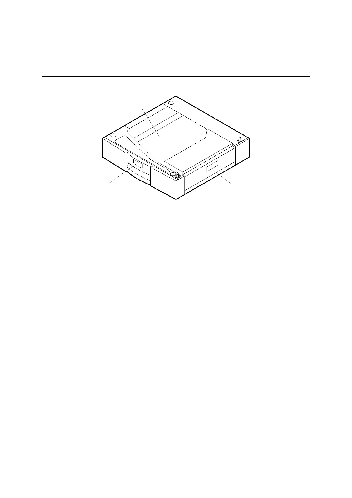
2.1 Names of Various Components
Cassette tray
Paper cassette
PFU open cover
PFU 02-01-01
October 2000 © TOSHIBA TEC 2 - 1 MY-1015 OUTLINE
Page 6
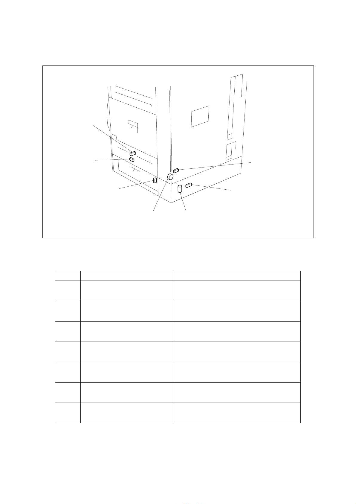
2.2 Layout of Electrical Parts
SEN2
SEN1
SW1
CL1
Symbols and functions of various devices
Symbol
SW1
2COV-SW
Name
PFU cover open switch
SW2
2CST-SW
PFU cassette switch
SEN1
2T-UP-SEN
SEN3
SW2
M1
PFU 02-02-01
Function
Detects the open/close state of the cover during
jam processing, etc.
Detects the open/close state of the cassette.
Detects the lift-up of the tray.
PFU tray-up sensor
SEN2
SEN3
CL1
M1
2PE-SEN
PFU paper empty sensor
2PNE-SEN
PFU paper near empty sensor
2PU-CLT
PFU pickup clutch
2T-UP-MOT
Detects the presence or absence of paper placed
in the PFU cassette.
Detects a paper near empty state of the PFU
cassette. (option)
Transmits driving force to the rollers to pick up
and transport the paper.
Lifts up the tray of the PFU cassette.
PFU tray-up motor
MY-1015 OUTLINE 2 - 2 October 2000 © TOSHIBA TEC
Page 7
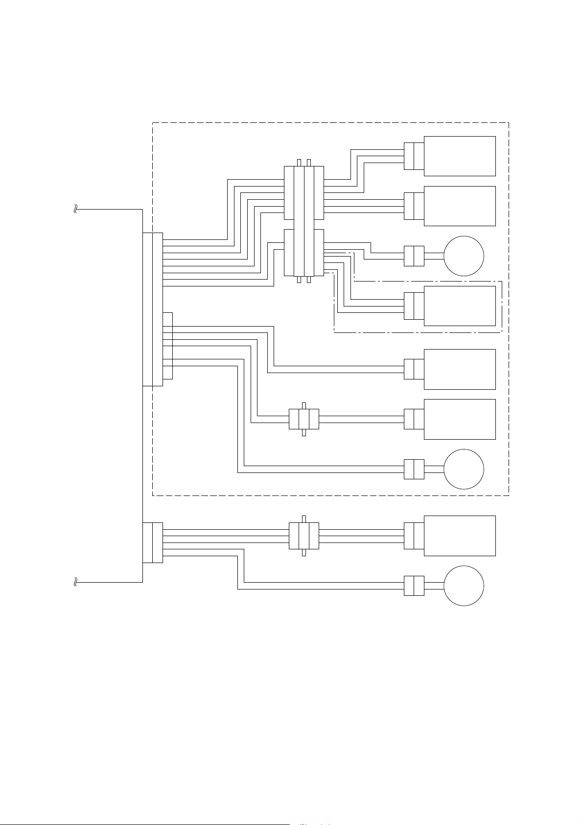
2.3 Harness Connection Diagram
PFU
CN208
PFUPEMP
PFUTUP A5
PFUPCLT A7
PFUTRM-A B8
GND A1
VDD A3
GND
VDD
+24V
VDD A9
GND A11
NC B2
GND B6
1
2
A2
3
4
A4
5
6
A6
7
8
A8
9
10
A10SIZPFU1
11
B1PFUCNT
12
B3SIZUPFU0
B4GND
B5PFUCOV
B7NC
B9PFUTRM-B
B10NC
B11GND
CN316A
CN316B
CN315
3
2
1
7
6
5
4
3
2
1
6
5
4
3
2
1
1
2
3
4
5
6
7
1
2
3
4
5
6
CN314
CN318
CN344
3
2
1
2
1
3
2
1
PFU
paper empty sensor
PFU
pickup sensor
PFU
pickup clutch
PFU
paper near empty
sensor
Not used
CN334
2
PFU cassette switch
1
PFC PWA
CN205
GND 1
PFUFD-SW
VDD 3
PFUFDCLT
+24V 5
CN317
211
2
CN165
1
2
2
3
4
4
1
3
2
2
3
1
CN345
CN319
CN154
CN163
2
PFU cover open switch
1
1
2
3
2
1
2
1
tray-up motor
2nd feed sensor
PFU
2nd feed
clutch
PFU 02-03-01
October 2000 © TOSHIBA TEC 2 - 3 MY-1015 OUTLINE
Page 8

3. OPERATIONAL DESCRIPTION
3.1 General Operation
The PFU is an additional paper feed unit (2nd cassette) and installed under the standard cassette (copier).
This unit has no PWA and its transport operation and detection are performed through the PFC PWA.
3.2 Block Diagram
PFU
PFC
PWA
CN208
PFUTRM-A,B
PFUPEMP
PFUTUP
PFUPCLT
SIZEPFU0
PFUCOV
PFU tray-up motorM
PFU paper empty sensor
PFU pickup sensor
PFU pickup clutch
PFU cassette switch
PFU cover open switch
PFU 03-02-01
The PFU consists of the paper feed cassette, four sensors, one magnetic clutch, and one tray-up motor.
October 2000 © TOSHIBA TEC 3 - 1 MY-1015 OPERATIONAL DESCRIPTION
Page 9

3.3 Detection of Abnormal Status
3.3.1 Cover open/Close detection
When the PFU cover open switch detects the open state of the cover, the copier detects it to stop the
transport of paper.
3.3.2 Paper empty detection
When there is no paper in the cassette tray or the PFU paper empty sensor detects the absence of paper
during printing, the operation is stopped. The absence of paper is detected only when the cassette is
closed.
3.3.3 Paper jam detection
The PFU itself has no feed sensor but installation of the PFU allo ws the sensor (2nd cassette f eed sensor)
on the copier side to be effectiv e . When transporting the paper, if the 2nd cassette f eed sensor does not
detect the passing of paper or the paper is left detected for a fix ed time, the progr am will judge it to be paper
jamming and stop the operation. The error state is reset b y opening and then closing the cover.
3.3.4 Tr a y-up motor failure
If no paper is detected or the tray-up upper limit is not reached even if a specified amount of time has
elapsed after the cassette is mounted, a tray-up motor failure will be assumed. To reset the error state,
once draw out the cassette.
MY-1015 OPERATIONAL DESCRIPTION 3 - 2 October 2000 © TOSHIBA TEC
Page 10

3.4 Flow Charts
Start button ON
Main motor ON
Polygon motor ON
Process unit fan motor high speed rotation
Development bias ON
Separation bias ON
Charge bias ON
Discharge lamp ON
Process system control Optical system control
Transfer system control
Retraction of carriage
Polygon motor
OK?
YES
Laser ON
Transfer bias ON
NO
Service call
"CA1"
Main motor
OK?
YES
PFU pickup clutch ON
2nd feed
NO
Service call
"C01"
NG
Black shading
Exposure lamp ON
Stop of carriage
sensor check
Transfer guide bias ON
Laser OFF
OK
Feed sensor
Paper jam
"E14"
NG
Advance of carriage
White shading
check
Transfer bias OFF
Transfer guide bias OFF
OK
PFU pickup clutch OFF
Paper jam
"E31"
Scanning of document
Stop of carriage
HSYNC
NO
2nd feed clutch ON
Exposure lamp OFF
OK
NO
Remaining
copy count 0?
Polygon motor OFF
End of process
YES
YES
Service call
"CA2"
2nd feed clutch OFF
NO
Remaining
copy count 0?
A
YES
Retraction of carriage
Stop of carriage
End of optical
system control
system control
October 2000 © TOSHIBA TEC 3 - 3 MY-1015 OPERATIONAL DESCRIPTION
Page 11

A
Exit sensor
NG
check 1
Paper jam
OK
Exit sensor
"E01"
NG
check 2
Paper jam
OK
"E02"
Charge bias OFF
Main motor OFF
Development bias OFF
Separation bias OFF
Discharge lamp OFF
Power supply unit fan motor low speed rotation
Standby
MY-1015 OPERATIONAL DESCRIPTION 3 - 4 October 2000 © TOSHIBA TEC
Page 12

4. MECHANICAL DESCRIPTION
4.1 Paper Feed System
PFU pickup clutch
PFU cassette tray
PFU feed roller
PFU pickup roller
PFU tray-up motor (cupling)
Flow of paper
PFU 04-01-01
The PFU pickup clutch is used to turn ON and OFF the driving force of the main motor . It turns ON when
picking up the paper and transmits the driving force to the f eed roller and pickup roller through the shaft and
belt. When the pickup clutch is turned ON to transport the paper, the feed roller and pickup roller turn and
the pickup roller begins to pick up the paper . When pic ked up , the paper is transported by the feed roller and
pulled into the transport path on the copier side.
The separate roller prevents the multi-feed of paper and contains a spring clutch. The roller separates
sheets of paper to prevent the feeding of multiple sheets of paper at a time.
October 2000 © TOSHIBA TEC 4 - 1 MY-1015 MECHANICAL DESCRIPTION
Page 13

4.2 Drive System
PFU pickup roller
PFU pickup clutch
Cupling
PFU tray-up motor
PFU 04-02-01
The PFU has no motor for transporting paper. Paper is transported by transmitting the driving force of the
main motor of the copier to the gear. The driving force from the copier side is transmitted to the PFU pickup
clutch through the gears (four pcs.). Installing the cassette causes the pickup roller to lower. The PFU
pickup clutch turns ON and OFF the gear driving force from the copier . When picking up the paper , it turns
ON to transmit the driving force to the feed roller and pickup roller through the shaft and belt. When the
pickup roller turns, the paper is picked up from the cassette and brought to the tr ansport path.
The tray-up operation is perf ormed by the PFU tra y-up motor . Consisting of the DC motor , w orm gear, gear,
coupling, etc., the PFU tray-up motor is housed within a case as a unit. When the cassette is installed, the
coupling of this motor unites with the coupling of the cassette to transmit the motor rotation to the arm
under the cassette and lift the cassette tray.
MY-1015 MECHANICAL DESCRIPTION 4 - 2 October 2000 © TOSHIBA TEC
Page 14

5. CIRCUIT DESCRIPTION
5.1 Meaning of Signals
Signal Name
PFUCOV
SIZPFU0
PFUTUP
PFUPEMP
PFUPCLT
PFUTRM-A, B
Part Name
PFU cover open
switch
PFU cassette
switch
PFU pickup
sensor
PFU paper
empty sensor
PFU pickup
clutch
PFU tray-up
motor
Functional Description
Detects the open/close
state of the cover during
jam processing, etc.
Detects the open/close
state of the cassette.
Detects the lift-up of the
cassette.
Detects the presence or
absence of paper placed
in the PFU cassette.
Operation signal for feed
clutch.
Lifts up the tray of the PFU
cassette.
Status
High: Open
Low: Cassette present
High: Paper feed
enabled
High: Paper absent
Low: ON
Low, High = Up
Note
Push switch
Push switch
Photo sensor
Photo sensor
Magnetic clutch
Brush motor
The PFU cover open switch detects the open or close state of the cover. A push switch is used for the
switch. The signal goes LOW when the cover is closed, and HIGH when it is open.
The PFU cassette switch is a s witch which detects the open or close state of the cassette. A push switch
is used for the switch. The signal goes LOW when the cassette is mounted, and HIGH when it is open.
The PFU pickup sensor is a switch which detects the lift-up of the cassette . A photo sensor is used for the
switch. Paper feed is enabled when the signal is at “High” level.
The PFU paper empty sensor detects the presence or absence of paper. A photo sensor is used for the
sensor. There is no paper when the signal is at “High” level.
PFU pickup clutch is an operation signal for the feed clutch and drives the magnetic clutch. Driving f orce
is transmitted to the pickup roller when the signal is at “Low” le vel.
The PFU tray-up motor lifts the tray of the cassette. The combination of the two signals permits setting of
lifting, braking, and OFF.
October 2000 © TOSHIBA TEC 5 - 1 MY-1015 CIRCUIT DESCRIPTION
Page 15

5.2 Timing Chart
2.67s
1.88s
810ms
750ms
350ms
20ms
PFU pickup
clutch
MY-1015 CIRCUIT DESCRIPTION 5 - 2 October 2000 © TOSHIBA TEC
Option cassette
340ms
feed clutch
Option cassette
feed sensor
Feed sensor
The values are data (reference v alues) applicab le when the A4 siz e paper is used.
PFU 05-02-01
Page 16

6. DISASSEMBLY AND REPLACEMENT
[A] PFU rear cover
1. Remove 3 screws, release 2 hooks, and detach
PFU rear cover.
PFU right cover
Screw
Hook
[B] PFU right cover F
2. Open PFU open cover, remove 2 screws, and
detach PFU right cover F.
[C] PFU right cover R
1. Remove 2 screws and detach PFU right cover
R.
PFU right cover F
Fig. 6-1
Fig. 6-2
Hook
Screw
Screw
193
PFU open
cover
194
PFU right cover R
Screw
195
Fig. 6-3
[D] PFU blind cover
Note: This cover cannot be used with PFP-1 in-
stalled.
1. Detach PFU right cover R. (See Fig. 6-3)
2. Release 2 hooks and detach PFU blind cov er.
PFU blind cover
196
Fig. 6-4
October 2000 © TOSHIBA TEC 6 - 1 MY-1015 DISASSEMBLY AND REPLACEMENT
Page 17

[E] PFU open cover
1. Detach PFU right cover F. (See Fig. 6-2)
2. Release 2 hooks and detach PFU switch co ver.
3. Release 2 hook, detach one connector , and remove PFU open cover switch.
PFU switch cover
PFU open cover switch
Connector
Hook
197
Fig. 6-5
Hook
4. Remove one scre w , release brac ket hook F, and
detach PFU open cover.
[F] PFU left cover R
1. Detach PFU rear cov er. (See Fig. 6-1)
2. Release 5 hooks and detach PFU left cover R.
Bracket hook F
Hook
PFU left
cover R
Fig. 6-6
Screw
Fig. 6-7
198
PFU open cover
199
Hook
200
Fig. 6-8
MY-1015 DISASSEMBLY AND REPLACEMENT 6 - 2 October 2000 © TOSHIBA TEC
Page 18

[G] PFU left cover
1. Detach PFU rear cover. (See Fig. 6-1)
2. Remove paper cassette of PFU and paper cassette of the copier.
Paper cassette
201
Fig. 6-9
3. Remove 17 scre ws and detach rear co ver.
4. Detach 3 harnesses from PFC PWA (CN206/
CN207/CN208).
5. Remove one screw and detach the ground wire
from the copier.
Screw
Ground wire
Rear cover
Screw
Fig. 6-10
CN206
Screw
Screw
202
PFC PWA
CN207
Fig. 6-11
CN208
203
6. Remove 2 screws and remove fixing plate R.
Fixing plate R
Screw
204
Fig. 6-12
October 2000 © TOSHIBA TEC 6 - 3 MY-1015 DISASSEMBLY AND REPLACEMENT
Page 19

7. Remov e 4 screws and remove fixing plate F.
8. Remov e PFU from the copier.
Fig. 6-13
Screw
ScrewFixing plate F
205
Copier
PFU
9. If a PFP-1 (KD-1009) or the LCF (KD-1010) is a
attached to the copier, detach it.
10. Detach PFU rear cover (See Fig. 6-1)
11. Detach PFU left cover R. (See Fig. 6-8)
12. Remove 10 screws, release 10 tabs, and detach PFU left cover.
[H] Tray-up assembly
1. Detach PFU rear cov er. (See Fig. 6-1)
2. Remov e paper cassette of PFU. (See Fig. 6-9)
3. Remove 2 screws, detach the relay connector,
and remove tray-up assembly.
Screw
Screw
Fig. 6-14
Fig. 6-15
206
Screw
Screw
PFU left cover
207
Connector
Tray-up
assembly
Screw
Fig. 6-16
MY-1015 DISASSEMBLY AND REPLACEMENT 6 - 4 October 2000 © TOSHIBA TEC
208
Page 20

[I] PFU joint gear assembly
1. Detach PFU rear cover. (See Fig. 6-1)
2. Remove paper cassette of PFU. (See Fig. 6-9)
3. Remov e tray-up assembly. (See Fig. 6-16)
4. Release the clamp.
5. Remove 2 scre ws , release the tab , and remov e
PFU joint gear assembly.
[J] PF separate roller
1. Remove paper cassette of PFU and paper cassette of the copier. (See Fig. 6-9)
2. Remove one screw and remove PF pickup assembly.
3. Remove one screw and remove PF separate
holder assembly.
PFU joint gear
assembly
Screw
Fig. 6-17
PF pickup assembly
Fig. 6-18
Screw
Clamp
Screw
209
210
PF separator
holder assembly
211
Fig. 6-19
4. Pull up and take out separate roller lever.
5. Remove arbor F, draw out shaft, and remove
separate roller, separate spring, arbor R, and
Separator spring
Separator roller
Shaft
spring cover in this order.
Notes: 1. To detach/attach the separate roller from/
to the separate spring, rotate the separate roller in the direction of the arrow.
2. Since the separate spring is coated with
Spring cover
Arbor R
Spring
Arbor F
212
oil, the separate roller should not to be
touched by the separate spring.
October 2000 © TOSHIBA TEC 6 - 5 MY-1015 DISASSEMBLY AND REPLACEMENT
Fig. 6-20
Page 21

[K] Pickup feed roller
1. Remove paper cassette of PF and paper cassette of the copier. (See Fig. 6-9)
2. Remov e PF pic kup assembly. (See Fig. 6-18)
3. Remov e PF separate holder assemb ly.
(See Fig. 6-19)
4. Detach stop ring and remove pickup feed roller.
[L] Pickup roller
1. Remove paper cassette of PFU and paper cassette of the copier. (See Fig. 6-9)
2. Remov e PF pic kup assembly. (See Fig. 6-18)
3. Release the two hooks.
4. Release the timing belt and remove the pickup
roller shaft assembly.
Stop ring
Pickup feed
roller
Clutch
213
Fig. 6-21
Pickup roller shaft
assembly
5. Detach the E-ring and remove pickup roller gear
and clutch.
Hook
E-ring
Clutch
Pulley
Fig. 6-22
Fig. 6-23
Timing belt
214
Pickup roller
215
MY-1015 DISASSEMBLY AND REPLACEMENT 6 - 6 October 2000 © TOSHIBA TEC
Page 22

1-1, KANDA NISHIKI-CHO, CHIYODA-KU, TOKYO , 101-8842 JAPAN
 Loading...