

Page 1
SUPER MODULAR MULTI
R410A
Quick reference
FILE NO : A04-004
Page 2
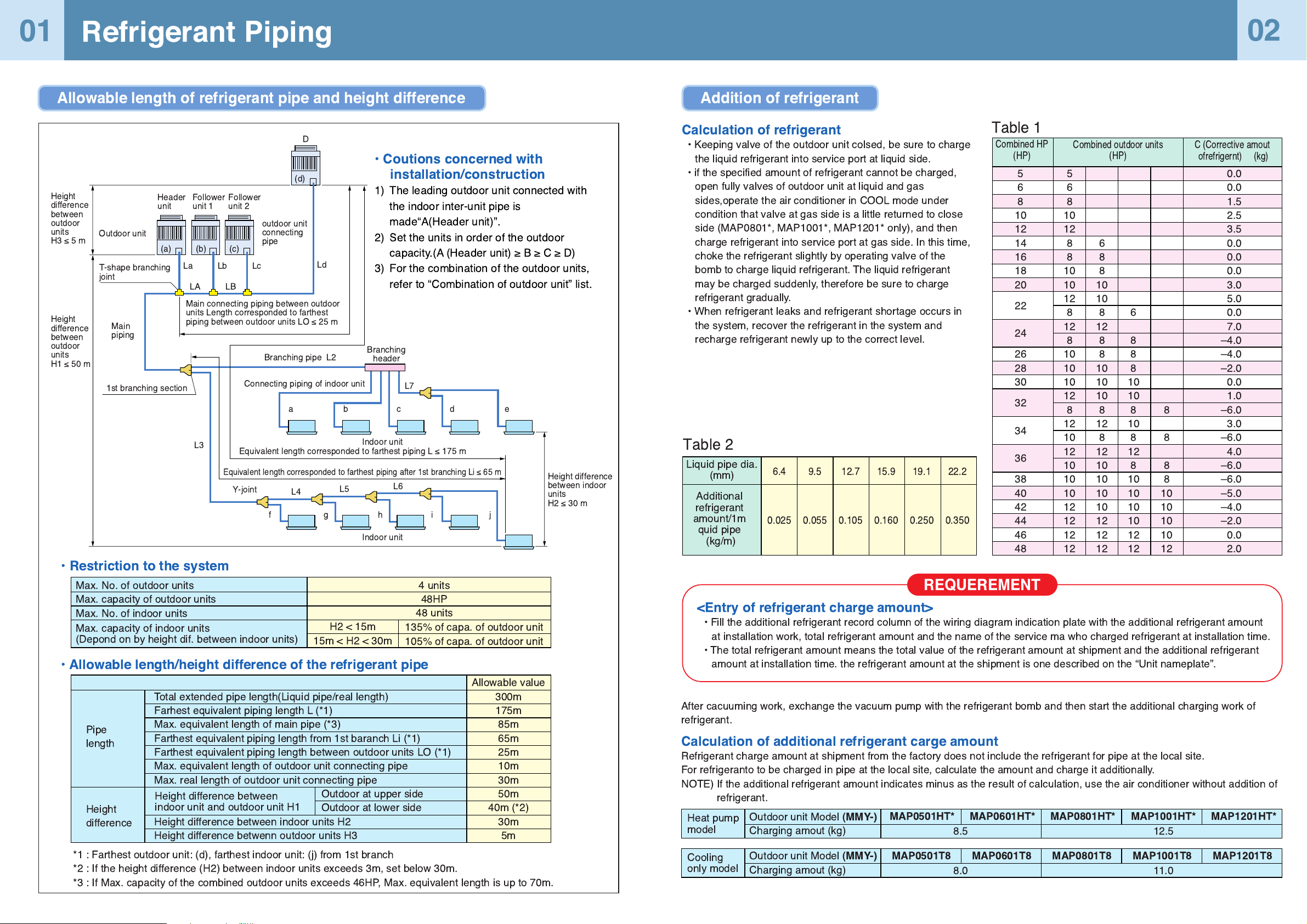
Pipe
length
Height
difference
Total extended pipe length(Liquid pipe/real length)
Farhest equivalent piping length L (*1)
Max. equivalent length of main pipe (*3)
Farthest equivalent piping length from 1st baranch Li (*1)
Farthest equivalent piping length between outdoor units LO (*1)
Max. equivalent length of outdoor unit connecting pipe
Max. real length of outdoor unit connecting pipe
Outdoor at upper side
Outdoor at lower side
Height difference between indoor units H2
Height difference betwenn outdoor units H3
Allowable value
300m
175m
85m
65m
25m
10m
30m
50m
40m (*2)
30m
5m
Height difference between
indoor unit and outdoor unit H1
*1 : Farthest outdoor unit: (d), farthest indoor unit: (j) from 1st branch
*2 : If the height difference (H2) between indoor units exceeds 3m, set below 30m.
*3 : If Max. capacity of the combined outdoor units exceeds 46HP, Max. equivalent length is up to 70m.
Calculation of refrigerant
¥ Keeping valve of the outdoor unit colsed, be sure to charge
the liquid refrigerant into service port at liquid side.
¥ if the specified amount of refrigerant cannot be charged,
open fully valves of outdoor unit at liquid and gas
sides,operate the air conditioner in COOL mode under
condition that valve at gas side is a little returned to close
side (MAP0801*, MAP1001*, MAP1201* only), and then
charge refrigerant into service port at gas side. In this time,
choke the refrigerant slightly by operating valve of the
bomb to charge liquid refrigerant. The liquid refrigerant
may be charged suddenly, therefore be sure to charge
refrigerant gradually.
¥ When refrigerant leaks and refrigerant shortage occurs in
the system, recover the refrigerant in the system and
recharge refrigerant newly up to the correct level.
<Entry of refrigerant charge amount>
¥ Fill the additional refrigerant record column of the wiring diagram indication plate with the additional refrigerant amount
at installation work, total refrigerant amount and the name of the service ma who charged refrigerant at installation time.
¥ The total refrigerant amount means the total value of the refrigerant amount at shipment and the additional refrigerant
amount at installation time. the refrigerant amount at the shipment is one described on the ÒUnit nameplateÓ.
After cacuuming work, exchange the vacuum pump with the refrigerant bomb and then start the additional charging work of
refrigerant.
Calculation of additional refrigerant carge amount
Refrigerant charge amount at shipment from the factory does not include the refrigerant for pipe at the local site.
For refrigeranto to be charged in pipe at the local site, calculate the amount and charge it additionally.
NOTE) If the additional refrigerant amount indicates minus as the result of calculation, use the air conditioner without addition of
refrigerant.
Combined HP
(HP)
Combined outdoor units
(HP)
C (Corrective amout
ofrefrigernt) (kg)
Table 1
Table 2
5
6
8
10
12
14
16
18
20
22
24
26
28
30
32
34
36
38
40
42
44
46
48
5
6
8
10
12
8
8
10
10
12
8
12
8
10
10
10
12
8
12
10
12
10
10
10
12
12
12
12
6
8
8
10
10
8
12
8
8
10
10
10
8
12
8
12
10
10
10
10
12
12
12
6
8
8
8
10
10
8
10
8
12
8
10
10
10
10
12
12
8
8
8
8
10
10
10
10
12
0.0
0.0
1.5
2.5
3.5
0.0
0.0
0.0
3.0
5.0
0.0
7.0
Ð4.0
Ð4.0
Ð2.0
0.0
1.0
Ð6.0
3.0
Ð6.0
4.0
Ð6.0
Ð6.0
Ð5.0
Ð4.0
Ð2.0
0.0
2.0
Liquid pipe dia.
(mm)
Additional
refrigerant
amount/1m
quid pipe
(kg/m)
6.4
0.025
9.5
0.055
12.7
0.105
15.9
0.160
19.1
0.250
22.2
0.350
Heat pump
model
Outdoor unit Model
(MMY-)
Charging amout (kg)
MAP0501HT* MAP0601HT* MAP0801HT* MAP1001HT* MAP1201HT*
8.5 12.5
Cooling
only model
Outdoor unit Model
(MMY-)
Charging amout (kg)
MAP0501T8 MAP0601T8 MAP0801T8 MAP1001T8 MAP1201T8
8.0 11.0
REQUEREMENT
01
Refrigerant Piping
Allowable length of refrigerant pipe and height difference Addition of refrigerant
Max. No. of outdoor units
Max. capacity of outdoor units
Max. No. of indoor units
¥ Coutions concerned with
installation/construction
1) The leading outdoor unit connected with
the indoor inter-unit pipe is
madeÒA(Header unit)Ó.
2) Set the units in order of the outdoor
capacity.(A (Header unit) ³ B ³ C ³ D)
3) For the combination of the outdoor units,
refer to ÒCombination of outdoor unitÓ list.
02
D
(d)
(c)
(b)
(a)
La Lc
Ld
Lb
LA LB
Y-joint
aedcb
L7
L4
L6
L5
Outdoor unit
outdoor unit
connecting
pipe
Main connecting piping between outdoor
units Length corresponded to farthest
piping between outdoor units LO ² 25 m
T-shape branching
joint
Main
piping
1st branching section
L3
Indoor unit
Indoor unit
Height difference
between indoor
units
H2 ² 30 m
Equivalent length corresponded to farthest piping L ² 175 m
Equivalent length corresponded to farthest piping after 1st branching Li ² 65 m
Connecting piping of indoor unit
Branching pipe L2
Branching
header
Header
unit
Follower
unit 1
Follower
unit 2
Height
difference
between
outdoor
units
H3²5m
Height
difference
between
outdoor
units
H1 ² 50 m
¥ Restriction to the system
¥ Allowable length/height difference of the refrigerant pipe
Max. capacity of indoor units
(Depond on by height dif. between indoor units)
H2 < 15m
15m < H2 < 30m
135% of capa. of outdoor unit
105% of capa. of outdoor unit
4 units
48HP
48 units
fjihg
Page 3
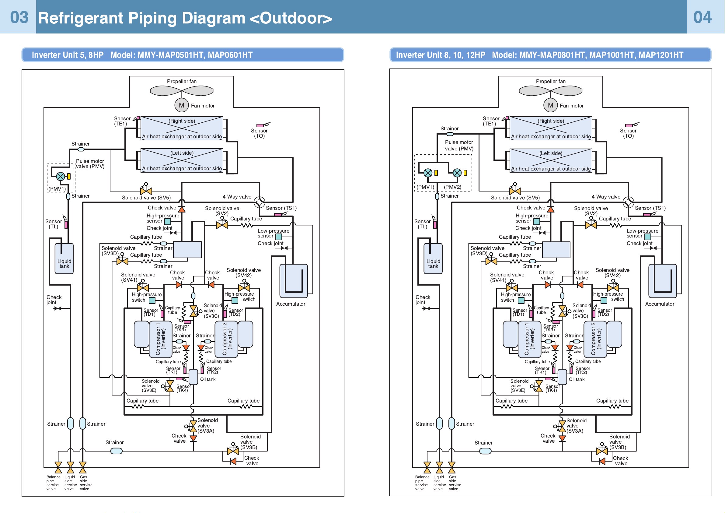
Refrigerant Piping Diagram <Outdoor>
Inverter Unit 5, 8HP Model: MMY-MAP0501HT, MAP0601HT
03
04
Capillary tube
Capillary
tube
Capillary tube
Propeller fan
Fan motor
Sensor
(TO)
Sensor (TS1)
Sensor
(TL)
Sensor
(TE1)
(Right side)
(Left side)
Solenoid valve
(SV2)
Solenoid valve (SV5)
Solenoid valve
(SV41)
Solenoid
valve
(SV3A)
Solenoid
valve
(SV3E)
Solenoid
valve
(SV3B)
Solenoid valve
(SV3D)
Solenoid
valve
(SV3C)
4-Way valve
Check joint
Low-pressure
sensor
Accumulator
Check joint
Check
joint
High-pressure
sensor
High-pressure
switch
Oil
separator
Check valve
Check
valve
Check
valve
Check
valve
Check
valve
Compressor 1
(Inverter)
Strainer
Strainer
Sensor
(TK1)
Sensor
(TK4)
Sensor
(TK3)
Capillary tube
Capillary tube
Capillary tube
Strainer
Strainer
Strainer
(PMV1)
Strainer
StrainerStrainer
Capillary tube
Capillary tube
Solenoid valve
(SV42)
High-pressure
switch
Check
valve
Check
valve
Compressor 2
(Inverter)
Strainer
Sensor
(TK2)
Sensor
(TD2)
Sensor
(TD1)
Liquid
tank
Oil tank
Balance
pipe
servise
valve
Liquid
side
servise
valve
Gas
side
servise
valve
Pulse motor
valve (PMV)
Air heat exchanger at outdoor side
Air heat exchanger at outdoor side
M
Inverter Unit 8, 10, 12HP Model: MMY-MAP0801HT, MAP1001HT, MAP1201HT
Capillary tube
Capillary
tube
Capillary tube
Propeller fan
Fan motor
Sensor
(TO)
Sensor (TS1)
Sensor
(TL)
Sensor
(TE1)
(Right side)
(Left side)
Solenoid valve
(SV2)
Solenoid valve (SV5)
Solenoid valve
(SV41)
Solenoid
valve
(SV3A)
Solenoid
valve
(SV3E)
Solenoid
valve
(SV3B)
Solenoid valve
(SV3D)
Solenoid
valve
(SV3C)
4-Way valve
Check joint
Low-pressure
sensor
Accumulator
Check joint
Check
joint
High-pressure
sensor
High-pressure
switch
Oil
separator
Check valve
Check
valve
Check
valve
Check
valve
Check
valve
Compressor 1
(Inverter)
Strainer
Strainer
Sensor
(TK1)
Sensor
(TK4)
Sensor
(TK3)
Capillary tube
Capillary tube
Capillary tube
Strainer
Strainer
Strainer
Strainer
StrainerStrainer
Capillary tube
Capillary tube
Solenoid valve
(SV42)
High-pressure
switch
Check
valve
Check
valve
Compressor 2
(Inverter)
Strainer
Sensor
(TK2)
Sensor
(TD2)
Sensor
(TD1)
Liquid
tank
Oil tank
Balance
pipe
servise
valve
Liquid
side
servise
valve
Gas
side
servise
valve
Pulse motor
valve (PMV)
Air heat exchanger at outdoor side
Air heat exchanger at outdoor side
M
(PMV1) (PMV2)
Page 4
Continued
Check Code List
05
06
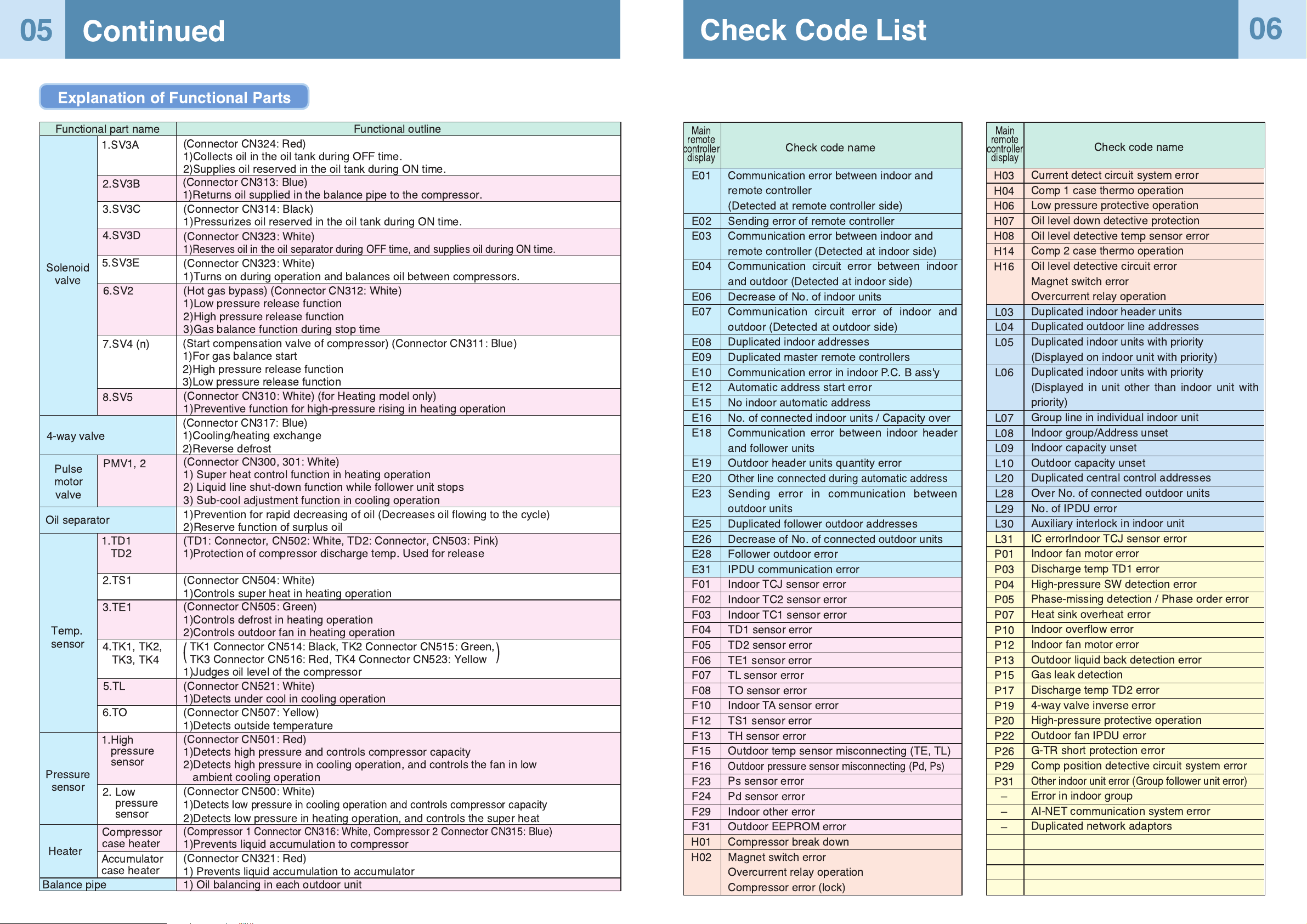
Explanation of Functional Parts
Functional outline
Solenoid
valve
Functional part name
4-way valve
Pulse
motor
valve
Oil separator
Temp.
sensor
Pressure
sensor
Heater
Balance pipe
(Connector CN324: Red)
1)Collects oil in the oil tank during OFF time.
2)Supplies oil reserved in the oil tank during ON time.
(Connector CN313: Blue)
1)Returns oil supplied in the balance pipe to the compressor.
1.SV3A
2.SV3B
3.SV3C
4.SV3D
6.SV2
5.SV3E
7.SV4 (n)
8.SV5
PMV1, 2
2.TS1
3.TE1
4.TK1, TK2,
TK3, TK4
5.TL
6.TO
2. Low
pressure
sensor
Compressor
case heater
1.TD1
TD2
1.High
pressure
sensor
Accumulator
case heater
(Connector CN314: Black)
1)Pressurizes oil reserved in the oil tank during ON time.
(Connector CN323: White)
1)Reserves oil in the oil separator during OFF time, and supplies oil during ON time.
(Connector CN323: White)
1)Turns on during operation and balances oil between compressors.
(Hot gas bypass) (Connector CN312: White)
1)Low pressure release function
2)High pressure release function
3)Gas balance function during stop time
(Start compensation valve of compressor) (Connector CN311: Blue)
1)For gas balance start
2)High pressure release function
3)Low pressure release function
(Connector CN310: White) (for Heating model only)
1)Preventive function for high-pressure rising in heating operation
(Connector CN317: Blue)
1)Cooling/heating exchange
2)Reverse defrost
(Connector CN300, 301: White)
1) Super heat control function in heating operation
2) Liquid line shut-down function while follower unit stops
3) Sub-cool adjustment function in cooling operation
1)Prevention for rapid decreasing of oil (Decreases oil flowing to the cycle)
2)Reserve function of surplus oil
(TD1: Connector, CN502: White, TD2: Connector, CN503: Pink)
1)Protection of compressor discharge temp. Used for release
(Connector CN504: White)
1)Controls super heat in heating operation
(Connector CN505: Green)
1)Controls defrost in heating operation
2)Controls outdoor fan in heating operation
TK1 Connector CN514: Black, TK2 Connector CN515: Green,
TK3 Connector CN516: Red, TK4 Connector CN523: Yellow
1)Judges oil level of the compressor
(Connector CN521: White)
1)Detects under cool in cooling operation
(Connector CN507: Yellow)
1)Detects outside temperature
(Connector CN501: Red)
1)Detects high pressure and controls compressor capacity
2)Detects high pressure in cooling operation, and controls the fan in low
ambient cooling operation
(Connector CN500: White)
1)
Detects low pressure in cooling operation and controls compressor capacity
2)Detects low pressure in heating operation, and controls the super heat
(Compressor 1 Connector CN316: White, Compressor 2 Connector CN315: Blue)
1)Prevents liquid accumulation to compressor
(Connector CN321: Red)
1) Prevents liquid accumulation to accumulator
1) Oil balancing in each outdoor unit
()
Communication error between indoor and
remote controller
(Detected at remote controller side)
Sending error of remote controller
Communication error between indoor and
remote controller (Detected at indoor side)
Communication circuit error between indoor
and outdoor (Detected at indoor side)
Decrease of No. of indoor units
Communication circuit error of indoor and
outdoor (Detected at outdoor side)
Duplicated indoor addresses
Duplicated master remote controllers
Communication error in indoor P.C. B ass'y
Automatic address start error
No indoor automatic address
No. of connected indoor units / Capacity over
Communication error between indoor header
and follower units
Outdoor header units quantity error
Other line connected during automatic address
Sending error in communication between
outdoor units
Duplicated follower outdoor addresses
Decrease of No. of connected outdoor units
Follower outdoor error
IPDU communication error
Indoor TCJ sensor error
Indoor TC2 sensor error
Indoor TC1 sensor error
TD1 sensor error
TD2 sensor error
TE1 sensor error
TL sensor error
TO sensor error
Indoor TA sensor error
TS1 sensor error
TH sensor error
Outdoor temp sensor misconnecting (TE, TL)
Outdoor pressure sensor misconnecting (Pd, Ps)
Ps sensor error
Pd sensor error
Indoor other error
Outdoor EEPROM error
Compressor break down
Magnet switch error
Overcurrent relay operation
Compressor error (lock)
Current detect circuit system error
Comp 1 case thermo operation
Low pressure protective operation
Oil level down detective protection
Oil level detective temp sensor error
Comp 2 case thermo operation
Oil level detective circuit error
Magnet switch error
Overcurrent relay operation
Duplicated indoor header units
Duplicated outdoor line addresses
Duplicated indoor units with priority
(Displayed on indoor unit with priority)
Duplicated indoor units with priority
(Displayed in unit other than indoor unit with
priority)
Group line in individual indoor unit
Indoor group/Address unset
Indoor capacity unset
Outdoor capacity unset
Duplicated central control addresses
Over No. of connected outdoor units
No. of IPDU error
Auxiliary interlock in indoor unit
IC errorIndoor TCJ sensor error
Indoor fan motor error
Discharge temp TD1 error
High-pressure SW detection error
Phase-missing detection / Phase order error
Heat sink overheat error
Indoor overflow error
Indoor fan motor error
Outdoor liquid back detection error
Gas leak detection
Discharge temp TD2 error
4-way valve inverse error
High-pressure protective operation
Outdoor fan IPDU error
G-TR short protection error
Comp position detective circuit system error
Other indoor unit error (Group follower unit error)
Error in indoor group
AI-NET communication system error
Duplicated network adaptors
E01
E02
E03
E04
E06
E07
E08
E09
E10
E12
E15
E16
E18
E19
E20
E23
E25
E26
E28
E31
F01
F02
F03
F04
F05
F06
F07
F08
F10
F12
F13
F15
F16
F23
F24
F29
F31
H01
H02
H03
H04
H06
H07
H08
H14
H16
L03
L04
L05
L06
L07
L08
L09
L10
L20
L28
L29
L30
L31
P01
P03
P04
P05
P07
P10
P12
P13
P15
P17
P19
P20
P22
P26
P29
P31
Ð
Ð
Ð
Check code name
Check code name
Main
remote
controller
display
Main
remote
controller
display
Page 5
SW04 SW05 SW15
D600 D601 D602 D603 D604
1
SW011SW021SW03
Header unit interface P.C. board
U1 U2 U3 U4 U5 U6
Header unit interface P.C. board
1 2 3 4
ON
SW11
1 2 3 4
ON
SW12
1 2 3 4
ON
SW06
1 2 3 4
ON
SW07
1 2 3 4
ON
SW09
1 2 3 4
ON
SW10
1
ON
SW08
1 2 3 4
ON
SW13
1 2 3 4
ON
SW14
UNIT
SET
CL
UNIT
SET
CL
For internal
wiring between
indoor and
outdoor
For wiring of
central control
system
For internal
wiring between
outdoor units
Address Setup
07
08
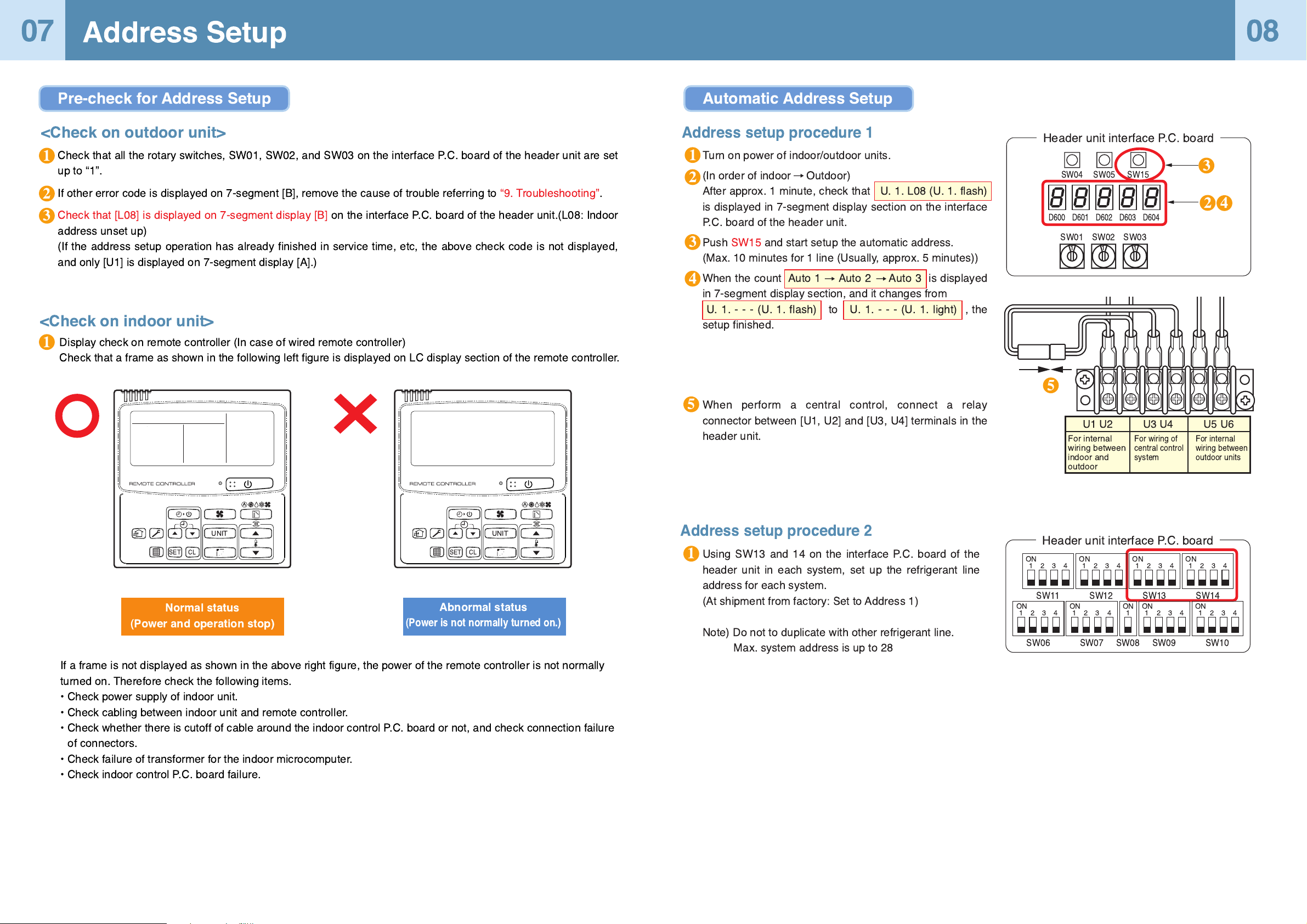
Check that all the rotary switches, SW01, SW02, and SW03 on the interface P.C. board of the header unit are set
up to Ò1Ó.
If other error code is displayed on 7-segment [B], remove the cause of trouble referring to Ò9. TroubleshootingÓ.
Check that [L08] is displayed on 7-segment display [B] on the interface P.C. board of the header unit.(L08: Indoor
address unset up)
(If the address setup operation has already finished in service time, etc, the above check code is not displayed,
and only [U1] is displayed on 7-segment display [A].)
<Check on outdoor unit>
Display check on remote controller (In case of wired remote controller)
Check that a frame as shown in the following left figure is displayed on LC display section of the remote controller.
<Check on indoor unit>
1
1
3
2
1
3
4
2
1
5
5
If a frame is not displayed as shown in the above right figure, the power of the remote controller is not normally
turned on. Therefore check the following items.
¥ Check power supply of indoor unit.
¥ Check cabling between indoor unit and remote controller.
¥ Check whether there is cutoff of cable around the indoor control P.C. board or not, and check connection failure
of connectors.
¥ Check failure of transformer for the indoor microcomputer.
¥ Check indoor control P.C. board failure.
Abnormal status
(Power is not normally turned on.)
Normal status
(Power and operation stop)
Pre-check for Address Setup Automatic Address Setup
Turn on power of indoor/outdoor units.
(In order of indoor Outdoor)
After approx. 1 minute, check that U. 1. L08 (U. 1. flash)
is displayed in 7-segment display section on the interface
P.C. board of the header unit.
Push SW15 and start setup the automatic address.
(Max. 10 minutes for 1 line (Usually, approx. 5 minutes))
When the count Auto 1 Auto 2 Auto 3 is displayed
in 7-segment display section, and it changes from
U. 1. - - - (U. 1. flash) to U. 1.---(U.1.light) , the
setup finished.
When perform a central control, connect a relay
connector between [U1, U2] and [U3, U4] terminals in the
header unit.
Address setup procedure 1
Address setup procedure 2
Using SW13 and 14 on the interface P.C. board of the
header unit in each system, set up the refrigerant line
address for each system.
(At shipment from factory: Set to Address 1)
Note) Do not to duplicate with other refrigerant line.
Max. system address is up to 28
3
4
2
Page 6
Ñ NOTE Ñ
Never connect a relay connector until address setup for all the refrigerant lines finishes;
otherwise address cannot be correctly set up.
After address setup
SW13, 14
(Line address)
SW30-2
Terminal-end resistance
of indoor/outdoor communi
cation line/central control
communication line
Relay connector
Indoor side (Automatic setup)
Line address
Indoor unit address
Group address
1
1
0
1
2
0
2
1
1
2
2
2
3
1
0
Connect short
after
address setup
Connect short
after
address setup
Connect short
after
address setup
Setup at shipment
from factory
U3 U4
U1 U2 U5 U6
U1 U2
A B
Header
unit
Header unit Header unit
Individual Group
Remote
controller
U3 U4
21
SW30
ON
OFF
U1 U2 U5 U6
U1 U2
A B
Follower unit
Remote
controller
Relay
connector
U3 U4
U1 U2 U5 U6
U1 U2
A B
Remote
controller
U3 U4
U1 U2 U5 U6
U1 U2
A B
Follower unit
U3 U4
U1 U2 U5 U6
U1 U2
A B
Remote
controller
Relay
connector
Relay
connector
Open
ON
1
2
12 3
3
1
Header unit Follower unit Follower unitHeader unit Header unit
ON
Open Open
OFF after
address setup
OFF after
address setup
(Setup is
unnecessary.)
(Setup is
unnecessary.)
(Setup is
unnecessary.)
(Setup is
unnecessary.)
Outdoor interface
P.C. board
21
SW30
ON
OFF
21
SW30 SW30
ON
OFF
21
SW30
ON
OFF
21
ON
OFF
Point
Relay connector
U1 U2
For internal
wiring between
indoor and
outdoor
U3 U4
For wiring of
central control
system
U5 U6
For internal
wiring between
outdoor units
SW04 SW05 SW15
D600 D601 D602 D603 D604
1
SW011SW021SW03
1 2 3 4
ON
SW11
1 2 3 4
ON
SW12
1 2 3 4
ON
SW06
1 2 3 4
ON
SW07
1 2 3 4
ON
SW09
1 2 3 4
ON
SW10
1
ON
SW08
1 2 3 4
ON
SW13
1 2 3 4
ON
SW14
12
ON
SW30
Header unit interface P.C. board
Continued
09
10
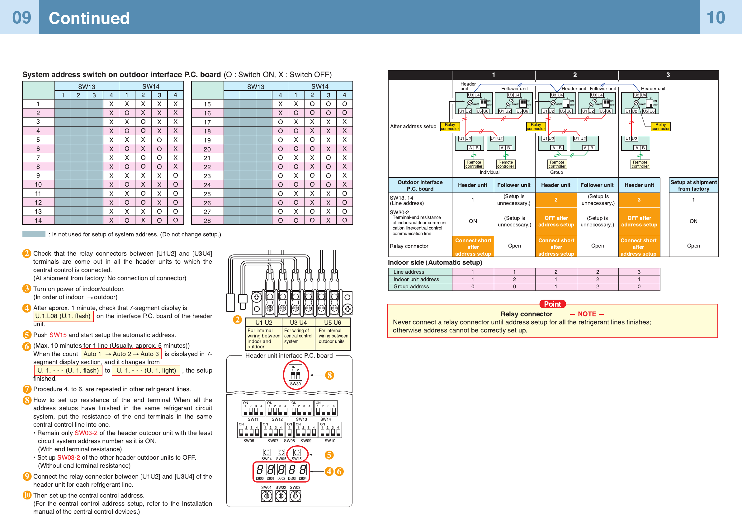
Check that the relay connectors between [U1U2] and [U3U4]
terminals are come out in all the header units to which the
central control is connected.
(At shipment from factory: No connection of connector)
Turn on power of indoor/outdoor.
(In order of indoor outdoor)
After approx. 1 minute, check that 7-segment display is
U.1.L08 (U.1. flash) on the interface P.C. board of the header
unit.
Push SW15 and start setup the automatic address.
(Max. 10 minutes for 1 line (Usually, approx. 5 minutes))
When the count Auto 1 Auto 2 Auto 3 is displayed in 7-
segment display section, and it changes from
U.1.---(U.1.flash) to U. 1.---(U.1.light) , the setup
finished.
Procedure 4. to 6. are repeated in other refrigerant lines.
How to set up resistance of the end terminal When all the
address setups have finished in the same refrigerant circuit
system, put the resistance of the end terminals in the same
central control line into one.
¥ Remain only SW03-2 of the header outdoor unit with the least
circuit system address number as it is ON.
(With end terminal resistance)
¥ Set up SW03-2 of the other header outdoor units to OFF.
(Without end terminal resistance)
Connect the relay connector between [U1U2] and [U3U4] of the
header unit for each refrigerant line.
Then set up the central control address.
(For the central control address setup, refer to the Installation
manual of the central control devices.)
1
2
3
4
5
6
7
8
9
10
11
12
13
14
SW13
4
X
X
X
X
X
X
X
X
X
X
X
X
X
X
12 3
SW14
1
X
O
X
O
X
O
X
O
X
O
X
O
X
O
2
X
X
O
O
X
X
O
O
X
X
O
O
X
X
3
X
X
X
X
O
O
O
O
X
X
X
X
O
O
4
X
X
X
X
X
X
X
X
O
O
O
O
O
O
15
16
17
18
19
20
21
22
23
24
25
26
27
28
SW13
4
X
X
O
O
O
O
O
O
O
O
O
O
O
O
SW14
1
X
O
X
O
X
O
X
O
X
O
X
O
X
O
2
O
O
X
X
O
O
X
X
O
O
X
X
O
O
3
O
O
X
X
X
X
O
O
O
O
X
X
X
X
4
O
O
X
X
X
X
X
X
X
X
O
O
O
O
System address switch on outdoor interface P.C. board
(O : Switch ON, X : Switch OFF)
: Is not used for setup of system address. (Do not change setup.)
5
3
4
7
8
9
10
8
6
2
2
5
4 6
Page 7

1 2 3 4
8
9
10 11
5 6 7
UNIT
SET
CL
UNIT No.
CODE No.
SET DATA
R.C. No.
Data Item code
11
1
4 7
10
3 6 9
2 5 8
Operation procedure
Wiring example in 2 lines Group address
end
1
2
3
4
5
6
7
8
9
10
11
++
11
12
Manual address setup from remote controller
Continued
Line address
Indoor address
Group address
Arrange one indoor unit and one remote controller set to 1 by 1.
Note 1)
When setting the line address from the remote controller, do not use address 29 and 30.
The address 29 and 30 cannot be set up in the outdoor unit. Therefore if they are incorrectly set
up, a check
code [E04] (Indoor/outdoor communication circuit error) is output.
Push simultaneously
buttons for 4 seconds or more.
LCD changes to flashing.
(Line address)
Using the setup temp.
buttons, set to the item code.
Using the timer time buttons, set
up the line address.
(Match it with the line address on the interface P.C. board
of the header unit in the identical refrigerant line.)
Push button.
(OK when display goes on.)
(Indoor address)
Using the setup temp.
buttons, set to the item code.
Using the timer time buttons, set
up the indoor address.
Push button.
(OK when display goes on.)
(Group address)
Using the setup temp.
buttons, set to the item code.
Using the timer time buttons, set
Individual = , Header unit = ,
Follower unit = .
Push button.
(OK when display goes on.)
Push button.
Setup operation finished.
(Status returns to normal stop status.)
In case to decide an address of the indoor unit prior to finish of indoor
cabling work and unpracticed outdoor cabling work
(Manual setup from
remote controller)
Turn on the power.
Outdoor
Header
#1
Indoor Indoor Indoor
Line address 1
Indoor address
1
Group address
1
Outdoor
#2
Indoor Indoor
Terminal
1
2
2
1
3
2
2
1
2
2
2
2
Remote
controller
In the above example, under condition of
no inter-unit wire of the remote controller,
set the address after individual connect-
ing of the wired remote controller.
Individual : 0000
Center unit : 0001
Terminal unit : 0002
} In case of group control
Page 8

13
14
Clearance of address (Return to status (Address undecided) at shipment from factory)
Method 1
Method 2
An address is individually cleared from a wired remote controller.
Point
Relay connector
SW30
left : SW30-1
right : SW30-2
MCU
Relay connector
Clearance of Indoor's Address
address Clear
SW01
2
2
1
2
2
2
After ÒA.d. c.L.Ó has been displayed on 7-degment display, return SW01/SW02/SW03 to 1/1/1.
When the address clearing has correctly finished, ÒU.1.L08Ó is displayed on 7-degment display after a while. If
ÒA.d. n.G.Ó is displayed on 7-degment display, there is a possibility which is connected with the other refrigerant
line. Check again the relay connector between [U1U2] and [U3U4] terminals.
NOTE) Be careful that the other refrigerant line address may be also cleared if clearing operation is not correctly
executed.
After clearing of the address, set up an address again.
Address which can be clearedSW04SW03SW02
Turn on the indoor/outdoor power of which address is to be cleared. After approx. 1 minute, check that ÒU.1.---Óis
displayed, and then execute the following operation on the interface P.C. board of the header unit of which address is
to be cleared in the refrigerant line.
1
3
2
Clear the indoor addresses in the same refrigerant line from the outdoor unit.
Item
code
line addoress
12
indoor address
13
group address
14
central address
03
<0099>
Turn off the power of the refrigerant line to be returned to the status at shipment, and change
the header unit to the following status.
1) Remove the relay connector between [U1U2] and [U3U4].(If it has been already removed,
leave it as it is.)
2) Turn on SW30-2 on the interface P.C. board of the header unit if it is OFF.(If it has been
already ON, leave it as it is.)
U3 U4
U1 U2 U5 U6
U1 U2
A B
Header unit
Remote
controller
U3 U4
U1 U2 U5 U6
U1 U2
A B
Follower unit
Remote
controller
U3 U4
U1 U2 U5 U6
U1 U2
A B
Remote
controller
U3 U4
U1 U2 U5 U6
U1 U2
A B
Follower unit
U3 U4
U1 U2
U1U3U2
U4
U5 U6
U1 U2
A B
Remote
controller
Center unitCenter unit Center unitCenter unitHeader unit Header unit
Central control
device
Unit of which address is to be returned to the initial status
After checking that ÒA.d.buSÓ is displayed on 7-
degment display, and then push SW04 for 5
seconds or more.
After checking that ÒA.d.nEtÓ is displayed on 7-
degment display, and then push SW04 for 5
seconds or more.
Line + Indoor + Group address
Central address
Page 9

Check code
displayed on
remote controller
E04
E16
E25
E26
L04
L05 (*)
L06
L08
Center unit
7-segment
display
E19-00
L08
E08-XX
E07
E06
E16-XX
E25
E26-XX
L04
L06
L08
Cause
Outdoor power is formerly turned on.
There is none of outdoor terminal resistance, or
there are two or more resistances.
(After address setup)
After address was decided, all the
indoor units do not correctly response
after power-ON in outdoor unit.
Address setup error
¥ Only line addresses of the connected indoor units
are undefined.
¥ The outdoor line address and the line addresses in
all indoor units do not match.
¥ The indoor addresses are duplicated.
(Units except those displaying E04 are duplicated.)
¥ A header unit is not set up in a group.
(Except group displaying E04)
Duplication of indoor addresses.
(Address No in which sub-code of the check code
are duplicated)
There is none of outdoor terminal
resistance, or there are two or more
resistances.
(After address setup, when terminal
resistance setup is changed after
power-ON.)
Transmission circuit error at interface side
(P.C. board failure)
After address setup, communication from all the
indoor units interrupted under condition that a
normal operation can be performed.
Exceeded No of connected indoor units or
exceeded capacity.
Duplication of outdoor addresses.
(Only when outdoor address was manually set up)
No. of connected outdoor units decreased.
¥ When setting outdoor backup
¥ The power of follower unit is not turned on.
Duplication of outdoor line addresses
¥ Line address setup error, occurred after connec-
tion between U1, U2 and U3, U4 connectors
Duplicated of indoor units with priority
There are two or more indoor units set up with
priority.
Address setup error
¥ Only indoor addresses of all the connected indoor
units are undefined.
( * )[L05]: Displayed on the indoor unit set up with priority
[L06]: Displayed on the indoor unit except one set up with priority
Countermeasures
Turn on the power again.
(In order of Indoor Outdoor)
Check SW30 bit 2 of the header unit.
No connection between multiple refrigerant lines:
SW30 bit 20N
Connection between multiple refrigerant lines:
SW30 bit 2 of the connected header unit is turned
on only in one line.
Check and modifies disconnection of indoor/outdoor
communication line.(Communication line between
center unit and the leading indoor unit)
Check influence of communication noise.
Set up address again.
Set up address again.
Check SW30 bit 2 of the header unit.
No connection between multiple refrigerant lines:
SW30 bit 20N
Connection between multiple refrigerant lines:
SW30 bit 2 of the connected header unit is turned
on only in one line.
Replace the interface P.C. board.
Check and correct disconnection of indoor/outdoor
communication line.(Communication line between
header unit and the leading indoor unit)
Check influence of communication noise.
Adjust No of connected indoor units or capacity.
Do not use a manual setup for outdoor address.
Correct of cause of error occurrence
¥ If it occurred when setting backup, clear the error
after setup finish.
¥ If the power of follower unit is not turned on, turn
on the power.
Modify line address setup of the header unit
between lines. (Set up SW 13 and 14 on the
interface P.C. board.)
Set up priority to only one indoor unit.
Set up address again.
ON
1
SW30
2
ON
1
SW30
2
In check for No. of connected outdoor units and connected Indoor units
after address setup, diminished No. of connected units displayed.
(There are outdoor/indoor units which do not operate in a test operation.)
There is no display of a check code on 7-segment display on the interface
P.C. board of the header unit though there is indoor unit which does not
accept the operation from the remote controller.
Remote
controller status
No response
No display on
remote controller
(No line is output.)
7-segment
display of
center unit
Remote
controller status
7-segment
display of
center unit
None
None
Cause
Communication line is not connected between indoor and outdoor.
Line and indoor addresses are unset.
(Unit which does not response to remote controller)
The power of the header unit of the group is not turned on in indoor
group control.(Unit which does not response to remote controller)
Group address is set up to follower unit in the individual control.
(Unit which does not response to remote controller)
The power is not turned on.
(Unit which is not displayed on remote controller)
Remote controller is not connected with cable.
(Unit which is not displayed on remote controller)
Miscabling of remote controller
(Unit which is not displayed on remote controller)
Remote controller communication circuit error
(Unit which is not displayed on remote controller)
If 230V is incorrectly applied to the remote controller terminal, the
remote controller communication circuit fails.
Countermeasures
Modify cabling.
Set up address.
Turn on the power.
Set [0] to group address in case of individual
control.
Turn on the power.
Correct cabling.
Correct cabling.
Remove FASTON terminal connected to
remote controller terminals (A/B), and check
the voltage. If voltage is not applied, replace
P.C. board. (15 to 18V usually)
No response L08
E19-00
E19-02
E20-01
Cause
Line addresses and indoor addresses of all the connected indoor
units are unset.
There is no header unit of group control.
Indoor unit power is not turned on.
Indoor/outdoor communication line is not correctly
connected to the header unit. (Fig. 1)
(Indoor/outdoor cannot
communicate before address setup.)
There is none of outdoor terminal resistance, or there are two or
more resistances. (Before address setup)
When connecting indoor/outdoor communication line between
outdoor units under condition of connected communication line
between outdoor units (Fig. 2)
SW08 setup error
Address setup is performed with connecting indoor/outdoor
communication line between outdoor units. (Fig. 3)
Address setup is performed under condition of connecting between
multiple refrigerant lines. (Fig. 3)
Countermeasures
Set up addresses.
Set up group address.
Turn on the power again.
(In order of indoor outdoor)
Correct cabling.
Check SW30 bit 2 of the header unit.
No connection between multiple refrigerant
lines: SW30 bit 2 0N
Connection between multiple refrigerant lines:
SW30 bit 2 of the connected header unit is
turned on only in one line.
Correct cabling.
Turn all SW08 to OFF side.
Correct cabling.
Correct cabling.
Status
Number of connected
outdoor units is short.
Number of connected
indoor units is short.
Number of outdoor
units connected to
group is short in
group operation from
remote controller.
Cause
Miswiring of communication line between
outdoor units or unconnected cable (Fig. 4)
(Address setup operation has finished without
recognition of miswired follower unit.)
Miswiring of communication line between
indoor units or unconnected cable (Fig. 5)
(Address setup operation has finished without
recognition of miswired indoor unit.)
Remote controller is not connected with cable.
Miscabling of remote controller
Remote controller communication circuit error
If 230V is incorrectly applied to the remote
controller terminal, the remote controller
communication circuit fails.
Countermeasures
After modification of wiring, set up address again and check No. of the
connected outdoor units.
After modification of wiring, set up address again and check No. of the
connected indoor units.
Using the main remote controller connected to a group, start a test operation,
specify the unit which does not operate (Unit unconnected to group), and
then check cabling.
Using the main remote controller connected to a group, start a test operation,
specify the unit which does not operate (Unit unconnected to group).
Remove Fasten receptacle connected to remote controller terminals (A/B),
and check the voltage If voltage is not applied, replace P.C. board.
(15 to18V in normal time).
ON
1
SW30
2
15
16
A check Code is Displayed on the Remote Controller
1
Operation from remote controller is not accepted and a check code is dis-
played on 7-segment display of the interface P.C. board of the header unit.
2
3
4
Troubleshooting in Test Operation
Page 10

UNIT
SET
CL
UNIT No.
CODE No.
SET DATA
R.C. No.
UNIT
SET
CL
UNIT No.
CODE No.
SET DATA
R.C. No.
UNIT No.
CODE No.
UNIT
SET
CL
Operation procedure
1 2
1
2
2
4
3
1 2 3
End
End
End
1
2
Operate
1
3
2
UNIT
1
3
2
UNIT
5
6
4
Operation procedure
6
521 3
4
Operation procedure
SET
CL
UNIT
17
18
When using a remote controller with the model name RBC-ATM21E, the following
monitor functions can be used.
Monitor Function of Remote Controller Switch
Confirmation of indoor unit address and position by using the remote controller
Confirmation of indoor unit address and the position
When you want to know the indoor address
though position of the indoor unit itself can be
recognized;
(NOTE 1)
Only a part of indoor unit types is installed with
the discharge temperature sensor.This tempera-
ture is not displayed for other types.
(NOTE 2)
When the units are connected to a group, data
of the header indoor unit only can be displayed.
(NOTE 3)
01 : Compressor 1 only is ON.
10 : Compressor 2 only is ON.
11 : Both compressor 1 and 2 are ON.
Indoor unit data (NOTE 2)
System data
Item
code
00
01
02
03
04
05
06
08
0A
0b
0C
0d
Data name
Room temp (During control)
Room temp (Remote controller)
Indoor suction temp (TA)
Indoor coil temp (TCJ)
Indoor coil temp (TC2)
Indoor coil temp (TC1)
Indoor discharge temp (Tf) (NOTE 1)
Indoor PMV opening
No. of connected indoor units
Total HP of connected indoor units
No. of connected outdoor units
Total HP of indoor units
Unit
¡C
¡C
¡C
¡C
¡C
¡C
¡C
pulse
unit
HP
unit
HP
Display
format
X1
X1
X1
X1
X1
X 1/10
X10
X10
Outdoor unit individual data (NOTE 4, 5)
Item
code
10
11
12
13
14
15
16
17
18
19
1A
1b
1d
1E
1F
Data name
Compressor 1 discharge temp (Td1)
Compressor 2 discharge temp (Td2)
High-pressure sensor detention
pressure (Pd)
Low-pressure sensor detention
pressure (Ps)
Suction temp (TS)
Outdoor heat exchanger temp (TE)
Temp at liquid side (TL)
Outside ambient temp (TO)
Low-pressure saturation temp (TU)
Compressor 1 current (I1)
Compressor 2 current (I2)
PMV1 + 2 opening
Compressor 1, 2 ON/OFF
Outdoor fan mode
Outdoor unit HP
Unit
¡C
¡C
MPa
MPa
¡C
¡C
¡C
¡C
¡C
A
A
pulse
Ñ
Ñ
HP
Display
format
X1
X1
X 100
X 100
X1
X1
X1
X1
X1
X10
X10
X 1/10
(NOTE 3)
0to31
X1
(NOTE 4)
For item code, an example of the header unit is
described.
(NOTE 5)
The upper digit of the item code indicates the
outdoor unit No.
1 : Header unit (A)
2 : Follower unit (B)
3 : Follower unit (C)
4 : Follower unit (D)
Push + buttons simultaneously for 4 seconds or more to call up the service monitor mode.
Pushing button returns the display to the normal display.
If it stops, push button.
Push UNIT button.
(Operation while the air conditioner operates)
The unit NO is displayed on the LCD.
(Disappears after several seconds) The displayed
unit No indicates the line address and indoor address. (If
there is other indoor unit connected to the same remote
controller (Group control unit), other unit No is displayed
every pushing UNIT button.)
¥ To confirm the unit numbers in a group control;
(Operation while the air conditioner stops)
¥ To confirm all the unit numbers from an arbitrary wired
remote controller;
[To select another line address]
When you want to know position of the indoor unit
using the address
Procedure
Procedure
The indoor unit numbers in a group control are successively
displayed, and the corresponding indoor fan is turned on. (Operation
while the air conditioner stops)
(Operation while the air conditioner stops)
Procedure
The indoor unit No and position in the same refrigerant piping
can be confirmed. An outdoor unit is selected, the indoor unit
numbers in the same refrigerant piping are successively
displayed, and then its indoor unit fan is turned on.
Push + buttons simultaneously for 4 seconds
or more.
¥ Unit No is displayed.
¥ The fans of all the indoor units in a group control are
turned on.
Every pushing button, the indoor unit
numbers in the group control are successively
displayed.
¥ The firstly displayed unit No indicates the address of the
header unit.
¥ Only fan of the selected indoor unit is turned on.
Push button to finish the procedure.
All the indoor units in group control stop.
Push the timer time + buttons simultaneously
for 4 seconds or more.
Firstly, the line 1, item code (Address Change) is
displayed. (Select outdoor unit.)
Using + buttons, select the line
address.
Using button, determine the selected line address.
¥ The indoor unit address, which is connected to the
refrigerant pipe of the selected outdoor unit is displayed
and the fan is turned on.
Push button to return to procedure 2 ).
¥ The indoor address of another line can be succes- sively confirmed.
Push button to finish the procedure.
Every pushing button, the indoor unit numbers in the identical pipe are successively displayed.
¥ Only fan of the selected indoor unit operates.played and the fan is turned on.
1
53
6
1
2
UNIT
UNIT
Page 11

UNIT
SET
CL
UNIT No.
CODE No.
SET DATA
R.C. No.
UNIT
SET
CL
UNIT No.
CODE No.
SET DATA
R.C. No.
UNIT
SET
CL
UNIT No.
CODE No.
SET DATA
R.C. No.
4
1 2 3 4
8
End
5
6 7
1 2 3 4
8
End
End
5
6 7
2
3
4
5
4 6
6
7
8
Operation procedure
1
2
3
4
Operation procedure
5
6
1
3
2
4 6
7
8
Operation procedure
UNIT
SET
CL
UNIT No.
CODE No.
R.C. No.
19
20
Continued
Change of indoor address from remote controller
Here, if the unit No is not called up, the outdoor
unit in this line does not exist.
Push button, and then select a line
according to procedure .
Error in the indoor unit is cleared by button on the remote controller.
(Only error of the indoor unit connected with operating remote controller is cleared.)
Error Clearing Function
Clearing from the main remote controller
The status returns to
the normal status.
1 2 3
1
3
2
Section A
[Error clearing in outdoor unit]
(Operation while the air conditioner stops)
Procedure
(Operation while the air conditioner stops)
Procedure
Push simultaneously + + buttons for 4
seconds or more.
(The firstly displayed unit No indicates the header unit in
group control.)
In group control, select an indoor unit No to be changed
by button.
(The fan of the selected indoor unit is turned on.)
Using the setup temp. buttons,
set to the item code.
Using the timer time buttons, change
the displayed setup data to a data which you
want to change.
Using the button, select the unit No. to
be changed at the next time. Repeat the procedure
to and change the indoor address so that it is not
duplicated.
Push button.
Change of indoor address from wired remote controller
SET
CL
UNIT
¥ To change the indoor address in individual operation (Wired
remote controller : Indoor unit=1:1)orgroup control
(When the setup operation with automatic address has finished,
this change is available.)
¥ To change all the indoor addresses from an arbitrary wired
remote controller;
(When the setup operation with automatic
address has finished, this change is available.)
Contents :
Using an arbitrary wired remote controller, the indoor
unit address can be changed for each same refrigerant piping line
Change the address in the address check/change mode.
SET
UNIT
After the above change, push button to confirm
the changed contents.
Push the timer time + buttons simultaneously for 4
seconds or more.
Firstly, the line 1, item code (Address Change) is displayed.
Push button.
¥ The indoor unit address, which is connected to the refrigerant
pipe of the selected outdoor unit is displayed and the fan is
turned on.
First the current indoor address is displayed on the setup data.
(Line address is not displayed.)
Using + buttons, select the line address.
If it is acceptable, push button to finish confirmation.
UNIT
UNIT
SET
The indoor address of the setup data moves up/down by the
timer time buttons.
Change the setup data to a new address.
Push button.
(All the displays on LCD go on.)
Every pushing button, the indoor unit numbers in
the identical pipe are successively
displayed. Only fan of the selected indoor unit operates.
Repeat the procedure to and change all the indoor
addresses so that they are not duplicated.
Change the mode to service monitor mode by pushing
+ buttons simultaneously for 4 seconds or more.
Using buttons, set Ò Ó to item code.
The display in Section A in the following figure is counted
with interval of 5 seconds as
When the count arrives Ò Ó, the error is cleared.
*However, counting from Ò Ó is repeated on the display.
Push button to determine the setup data.
SET
CL
UNIT
SET
Push button to finish the procedure.
[Error clearing in indoor unit]
Error of the outdoor unit is cleared by the unit of one refrigerant circuit system to which the indoor
units operated by the remote controller. (Error of the indoor unit is not cleared.)
For clearing errors, the service monitor function of the remote controller is used.
Method
CL
When button is pushed, the status returns to the normal
status.
ÒÓÒÓÒÓÒÓÒÓÒÓ
5
2
1
3
4
8
5
6 7
1
2
3
Cancel of line selection
To finish the setup
8
6
7
1
2
Page 12

TYPE
Item code [10]
Type
1-way Air Discharge Cassette
4-way Air Discharge Cassette
2-way Air Discharge Cassette
1-way Air Discharge Cassette (Compact type)
Concealed Duct Standard
Concealed Duct High Static Pressure
Under Ceiling
High Wall
Floor Standing Cabinet
Floor Standing Concealed
Floor Standing
Ñ
Abbreviated Model name
MMU-AP XXX SH
MMU-AP XXX H
MMU-AP XXX WH
MMU-AP XXX YH
MMD-AP XXX BH
MMD-AP XXX H
MMC-AP XXX H
MMK-AP XXX H
MML-AP XXX H
MML-AP XXX BH
MMF-AP XXX H
Setup data
0001
0003
0005
0007
0009
0011
0012
0013
0015
0017
0018
0021
0023
~
Model
007
009
012
015
018
024
027
030
036
048
056
072
096
Ñ
Setup data
0000
0001
0002
0003
0004
0006
0007
0008
0010
0011
0013
~
Indoor unit capacity
Item code [11]
UNIT
SET
CL
UNIT No.
CODE No.
SET DATA
R.C. No.
21
22
Continued
Applied control
Table: Function selecting item numbers (DN)
(Items necessary to perform the applied control at the local site are described.)
DN
01
02
03
04
06
0d
0F
10
11
12
13
14
19
1E
28
29
2A
2E
30
31
32
33
40
5d
60
62
92
Item
Filter sign lighting
time
Dirty state of filter
Central control
address
Specific indoor unit
priority
Heating temp shift
Existence of
automatic cool/heat
mode
Cooling only
Type
Indoor unit capacity
Line address
Indoor unit address
Group address
Flap type
(Adjustment of air
direction)
Temp difference of
automatic cooling/
heating mode
selection COOL
HEAT,HEAT, COOL
Automatic reset of
power failure
Operation condition
of humidifier
Selection of option/
error input (CN70)
HA terminal (CN61)
select
Automatic elevating
grille
Ventilating fan
control
TA sensor selection
Temperature unit
select
Control for humidifier
(+ drain pump control)
High ceiling selection
(Air volume selection)
Timer set
(Wired remote
controller)
Smudging-proof
control clear
Outside interlock
release condition
Description
0000 : None 0001 : 150H
0002 : 2500H 0003 : 5000H
0004 : 10000H
0000 : Standard 0001 : High degree of dirt
(Half of standard time)
0001 : No.1 unit to 0064 : No.64 unit
0099 : Unfixed
0000 : No priority 0001 : Priority
0000 : No shift 0001 : +1¡C
0002 : +2¡C to 0010 : +10¡C
(Up to +6 recommended)
0000 : Provided 0001 : Not provided
(Automatic selection from
connected outdoor unit)
0000 : Heat pump 0001 : Cooling only
(No display of [AUTO] [HEAT])
0000 : (1-way air discharge cassette)
0001 : (4-way air discharge cassette) to 0037
0000 : Unfixed 0001 to 0034
0001 : No.1 unit to 0030 : No.30 unit
0001 : No.1 unit to 0064 : No.64 unit
0000 : Individual 0001 : Header unit of group
0002 : Follower unit of group
0000 : Not provided 0001 : Swing only
0004 : [4-way Air Discharge Cassette type] and [Under Ceiling type]
0000 : 0 deg to 0010 : 10deg
(For setup temperature, reversal of COOL/HEAT by ± (Data value)/2)
0000 : None 0001 : Reset
0000 : Usual 0001 : Condition ignored
(Detection control for heat exchanger temperature)
0000 : Filter input 0001 : Alarm input (Air washer, etc.)
0002 : Humidifier input
0000 : Usual 0001 : Leaving-ON prevention control
0000 : Unavailable 0001 : Available
(Standard, (Auto grille, Oil guard,
Oil guard panel) Auto grille panel)
0000 : Unavailable 0001 : Available
0000 : Body TA sensor 0001 : Remote controller sensor
0000 : ¡C (at factory shipment) 0001 : ¡F
0000 : None 0001 : Humidifier + Vaporizing system
(Pump ON)
0002 : Humidifier + Ultrasonic system
(Pump ON after specified time passed) (Unused)
0003 : Humidifier + Natural drain system (Pump OFF)
[4-way Air Discharge Cassette type] and [Under Ceiling type]
0000 : Standard filter
0001 : Super-long life
[Concealed Duct Standard type]
0000 : Standard static pressure 0001 : High static pressure 1
(40Pa) (70Pa)
0003 : High static pressure 2 0005 : Correspond to quiet sound
(100Pa) 0006 : Low static pressure (20Pa)
0000 : Available (Operable) 0001 : Unavailable(Operation prohibited)
0000 : Clear
0000 : Operation stop 0001 : Release communication signal
receive
At shipment
According to type
0000 : Standard
0099 : Unfixed
0000 : No priority
0002 : +2¡C
(Floor type 0000: 0¡C)
0001 : Not provided
0000 : Heat pump
According to model type
According to capacity type
0099 : Unfixed
0099 : Unfixed
0099 : Unfixed
According to type
0003 : 3 deg
(Ts±1.5)
0000 : None
0000 : Usual
0002 : Humidifier
0000 : Usual
(HA terminal)
0000 : Unavailable
0000 : Unavailable
0000 : Body TA sensor
0000 : ¡C
0003 : Humidifier ON,
Pump OFF
0000 : Standard
0000 : Available
4- way Air Discharge
Cassette type only
0000 : Operation stop
Push , ,and buttons simultaneously for 4
seconds or more.
The firstly displayed unit No. indicates the header indoor
unit address in the group control.
In this time, the fan of the selected indoor unit is turned on.
SET
CL
1
Every pushing button, the indoor unit numbers
in the group control are successively displayed. In this
time, the fan of the selected indoor unit only is turned
on.
2
UNIT
Select the setup data using the timer time and
buttons.
(When selecting the DN code to Ò33Ó, change the
temperature indication of the unit from Ò¡CÓ to Ò¡FÓ on
the remote controller.)
4
Specify the item code (DN) using the setup temperature
and buttons.
3
Push button. (OK if display goes on.)
¥ To change the selected indoor unit, return to procedure .
¥ To change the item to be set up, return to procedure .
5
SET
2
3
Pushing button returns the status to normal stop
status.
6
2
1
3
4
6
5
Execute the setup operation while the unit stops.
Procedure
Page 13

NOTE 1) This start/stop function only sends the signals from the outdoor unit to the indoor unit, such as start, stop,
operation mode, etc. It does not resend the signals even if the indoor unit does not follow the sent signals.
NOTE 2) The above controls are not used during abnormal stop.
SW01
1
SW02
1
2
3
4
5
6
7
8
9
SW03
3
Display contents
Refrigerant name Displays refrigerant name. A B
Model with refrigerant R410A r4 10A
Model with refrigerant R407C r4 07C
System capacity A [ 5] to [48] :5 to 48HP
B [HP]
[P]
No. of outdoor units A [ 1] to [ 4] :1 to 4 units
B
No. of connected indoor units/ A [ 0] to [48] : 0 to 48 units (No. of connected units)
No. of units with cooling thermo ON
B [C0] to [C48]:0to48units (No. of units with cooling thermo ON)
No. of connected indoor units/ A [ 0] to [48] : 0 to 48 units (No. of connected units)
No. of units with heating thermo ON
B [H0] to [H48] :0 to 48 units (No. of units with heating thermo ON)
Compressor command A Data is displayed with hexadecimal notation
correction amount
B
Release control A Normal time :[ r], During release control: [r1]
BÑ
Oil-equalization control A Normal time :[oiL-0]
B During oil equation : [oiL-1]
Oil-equalization request A Displays with segment LED lighting pattern
B
10
11
12
13
14
15
16
Refrigerant/oil recovery operation A During sending of cooling refrigerant oil recovery signal : [C1].
Normal time :[C ]
B During sending of heating refrigerant oil recovery signal : [H1].
Normal time :[H ]
Automatic address A [Ad]
B Automatic addressing : [FF], Normal time : [ ]
Demand operation A [dU]
B Normal time :[ ]. In 50% to 90% : [ 50 to 90]
When controlling by communication line input : [E50 to E90]
Optional control (P.C. board input) Displays optioned control status A B
Operation mode selection : In heating with priority (Normal)
h.*
Priority on cooling
c.*
Heating only
H.*
Cooling only
C.*
Priority on No of operating indoor units.
n.*
Priority on specific indoor unit
U.*
Batch start/stop :Normal
Start input
Stop input
Night low-noise operation : Normal
Operation input
Snow fan operation : Normal
Operation input
*. *.
*.1.*.
*.ááá.*.
1.*.*.
ááá.*.*.
*.*.*.
*.*.*.
*.*.*.
*.*.*.
*.*.*.
*.*.*.
*.*.*.
*.*.*.
*.*.*.
*. *.
*. *.
Option control (BUS line input) Same as above
Unused
ÑA Ñ
BÑ
G
A
D
FB
EC
Dp
Display A Display B
F in the left figure goes on:
Header requests oil equalization.
C in the left figure goes on:
Follower requests oil-equalization.
(Outdoor unit number)
U2 U3 U4
*mark: Indicates none on display
*. *.
*.ááá.
*.1.
*.0.
No.
1
2
3
4
Function
Cooling test
operation
Heating test
operation
Batch start
Batch stop
Individual
start
Individual stop
Individual test
operation
Outline
Changes the mode of all the connected indoor
units collectively to cooling test operation.
Note) Control operation same as usual test
operation from remote control is
performed.
Changes the mode of all the connected indoor
units collectively to heating test operation.
Note) Control operation same as usual test
operation from remote control is
performed.
Starts all the connected indoor units collec-
tively.
Note) The contents follow to the setup of
remote controller.
Stops all the connected indoor units collec-
tively.
Starts the specified indoor unit.
Notes)
¥ The contents follow to the setup of remote
controller.
¥ The other indoor units keep the status as
they are.
Stops the specified indoor unit.
Note) The other indoor units keep the status
as they are.
Operates the specified indoor unit.
Note) The other indoor units keep the status
as they are.
Setup/Release
[Setup]
Push SW04 for 2 seconds or more
with SW01Ó2Ó, SW02Ó5Ó, SW03Ó1Ó.
[Release]
Return SW01, SW02, SW03 to Ò1Ó.
[Setup]
Push SW04 for 2 seconds or more
with SW01Ó2Ó, SW02Ó6Ó, SW03Ó1Ó.
[Release]
Return SW01, SW02, SW03 to Ò1Ó.
[Setup]
Push SW04 for 2 seconds or more
with SW01Ó2Ó, SW02Ó7Ó, SW03Ó1Ó.
[Release]
Return SW01, SW02, SW03 to Ò1Ó.
[Setup]
Push SW05 for 2 seconds or more
with SW01Ó2Ó, SW02Ó7Ó, SW03Ó1Ó.
[Release]
Return SW01, SW02, SW03 to Ò1Ó.
[Setup]
Push SW04 for 2 seconds or more set
SW01 Ò16Ó and set SW02 and SW03
to address No. (1 to 64) to be started.
[Release]
Return SW01, SW02, SW03 to Ò1Ó.
[Setup]
Push SW05 for 2 seconds or more set
SW01 Ò16Ó and set SW02 and SW03
to address No. (1 to 64) to be stopped.
[Release]
Return SW01, SW02, SW03 to Ò1Ó.
[Setup]
Push SW04 for 10 seconds or more
set SW01 Ò16Ó and set SW02 and
SW03 to address No. (1 to 64) to be
operated.
[Release]
Return SW01, SW02, SW03 to Ò1Ó.
7-segment display
Section A Section B
[C ] [ ÐC]
Section A Section B
[H ] [ ÐH]
Section A Section B
[CH] [ 11]
[ 11] is displayed on
Section B for 5 seconds.
Section A Section B
[CH] [ 00]
[ 00] is displayed on
Section B for 5 seconds.
Section A Section B
[] []
Section A:
Displays the corresponding
indoor address.
Section B:
Displays [ 11] for 5 seconds
from operation-ON.
Section A Section B
[] []
Section A:
Displays the corresponding
indoor address.
Section B:
Displays [ 00] for 5 seconds
from operation-OFF.
Section A Section B
[] []
Section A:
Displays the corresponding
indoor address.
Section B:
Displays [ FF] for 5 seconds
from test operation-ON.
23
24
SW04 SW05
7-segment display[B]
Interface P.C. board
Service Support Function
Indoor unit Start/Stop by Outdoor unit
Function to Start/Stop (ON/OFF) Indoor Unit from Outdoor Unit
1
The following functions of the indoor unit can start or stop by the switches on the interface P.C. board of the header unit.
SW01
Data display of system information (Displayed on the header outdoor unit only)
7-segment display[A]
<Rotary swich>
SW03SW02
Page 14

SW01
1
SW02
1
2
3
4
5
6
7
8
9
10
11
12
13
14
15
16
SW03
1
Display contents
Error data A Displays outdoor unit number: [U1] to [U4]
B Displays check code (Latest code only is displayed.)
There is no check code: [Ð Ð Ð]
There is sub-code: Check code [* * *] for 3 seconds,
sub-code [Ð * *] for 1 second alternately
<SW04> push function : Fan of unit with error only drives. 7-segment A: [E1]
<SW04 + SW05> push function : Fan of normal unit only drives. 7-segment A: [E0]
<SW05> push function : Interruption of fan operation function
ÑA Ñ
BÑ
Operation mode A Stop: [ ]
Normal cooling: [ C], Normal heating: [ H], Normal defrost: [ J]
BÑ
Outdoor unit HP A 5HP: [ 5], 6HP: [ 6], 8HP: [ 8], 10HP: [10], 12HP: [12]
B [HP]
Compressor operation command A No.1 compressor operation command is displayed.
Data display with Hexadecimal notation: [00 to FF]
B No.2 compressor operation command is displayed.
Data display with Hexadecimal notation: [00 to FF]
<SW04> push function : Inverter frequency is exchanged to decimal notation.
7-segment display (A/B) : [** ] [** H] (Normal display by pushing <SW05>)
Outdoor fan step A [FP]
B Step0to31:[0to31]
Compressor backup A Displays No.1 compressor setup status
Normal: [ ], Backup setup: [C1]
B Displays No.2 compressor setup status
Normal: [ ], Backup setup: [C2]
ÑA Ñ
BÑ
Control valve output data Displays control output status of solenoid valve A B
4-way valve: ON
H. 1
H. 0
2. 1
3. 1
2. 0
3. 0
3. 0
3. 0
4. ááá
4. ááá
ááá ááá
ááá ááá
4-way valve: OFF
SV2: ON / SV5: OFF
ááá 5. 0
ááá 5. 1
SV2: OFF / SV5: ON
SV3A: ON / SV3B: OFF / SV3C: OFF /SV3D: OFF
SV3A: OFF / SV3B: ON / SV3C: OFF /SV3D: OFF
SV3A: OFF / SV3B: OFF / SV3C: ON /SV3D: OFF
SV3A: OFF / SV3B: OFF / SV3C: OFF /SV3D: ON
SV41: ON / SV42: OFF
SV41: OFF / SV42: ON
Ñ
Ñ
PMV1 /PMV2 opening Displays opening data (Decimal) (Total opening)
**.P
ÑÑ
**.P
Oil level judgment status A [oL]
<SW05> push SW function: The following data is displayed for 2 seconds.
* During oil shortage in compressor 1: [Lááá ],
during oil shortage in compressor 2: [ááá L]
B Initial display: [ááá ááá ááá], Oil level judgment result: [A. #. * ]
Judgment result of compressor 1 in [#], compressor 2 in [*]
(0: Normal, 1, 2: Shortage) is displayed.
**
ááá *1
ááá ááá ááá
ááá ááá ááá
ááá ááá ááá
ááá ááá ááá
000
001
010
100
1 0 ááá
0 1 ááá
25
26
Data display of outdoor unit information (Displayed on each outdoor unit)
2
3
Data display of outdoor cycle (Displayed on each outdoor unit)
4
Data display of outdoor cycle (Displayed on the header unit)
Continued
* This method is used when information of the follower unit is displayed on 7-segment display of the header unit.
SW01
1
SW02
1
2
3
4
5
6
7
8
9
10
11
12
13
14
SW03
2
Display contents
Pd pressure data Pd pressure (MPaG) is displayed with decimal data.
(MPaG: Approx. 1/10 value of kg/cm
2
G data)
Ps pressure data Ps pressure (MPaG) is displayed with decimal data.
PL pressure conversion data
Estimated pressure of liquid line (MPaG) is displayed with decimal data.
TD1 sensor data Temperature sensor data (¡C) is displayed
with decimal notation.
TD2 sensor data
¥ Symbol displayfor 1 sec. and data display for 3 sec. are
alternately displayed.
TS sensor data
¥ Data is displayed in[*].
¥ Negative data is displayed as [Ð****].
TE sensor data
Ð
TL sensor data
TO sensor data
TK1 sensor data
TK2 sensor data
TK3 sensor data
TK4 sensor data
AB
Pd.
PS.
PL.
td
*
td
*
tS
*
tE
*
Ð
Ð
tL
*
to
*
F1
*
F2
*
F3
*
F4
*
Symbol
Data
Symbol
Data
Symbol
Data
Symbol
Data
Symbol
Data
Symbol
Data
Symbol
Data
Symbol
Data
Symbol
Data
Symbol
Data
Symbol
Data
SW01
3
SW02
1
2
3
4
5
6
7
SW03
1to3
Display contents
Error data A [U.*] * : SW03 setup number + 1 number (Outdoor unit number U2 to U4)
B Check code is displayed. (Latest check code only)
No check code: [Ð Ð Ð]
Installed compressor type A [U.*] * : SW03 setup number + 1 number (Outdoor unit number U2 to U4)
B
Outdoor unit capacity A [U.*] * : SW03 setup number + 1 number (Outdoor unit number U2 to U4)
B 8HP: [ááá ááá 8]. 10HP: [ááá 1 0], 5 to 12HP
Compressor operation command A [U.*] * : SW03 setup number + 1 number (Outdoor unit number U2 to U4)
B No.1 compressor ON: [C10], No.2 compressor ON: [C01]
For unconnected compressor ,ÒÐÓisdisplayed.
Fan operation mode A [U.*] * : SW03 setup number + 1 number (Outdoor unit number U2 to U4)
B Stop time: [F ááá 0], Mode 31: [F 3 1]
Release signal A [U.*] * : SW03 setup number + 1 number (Outdoor unit number U2 to U4)
B Normal time: [r ááá ááá ], Release received: [r ááá 1]
Oil level judgment A [U.*] * : SW03 setup number + 1 number (Outdoor unit number U2 to U4)
B Normal time: [ááá ááá ááá], Oil shortage: [ááá ááá L]
NOTE) The follower unit is setup by changing SW03.
SW03
7-segment display A
123
U2 U3 U4
*.**
*.**
*.**
1
**.*
2
**.*
**.*
**.*
Ð
Ð
**.*
**.*
**.*
**.*
**.*
**.*
Page 15

SW03
1
2
3
SW02
1to16
1to16
1to16
Indoor address
SW02 setup number
SW02 setup number + 16
SW02 setup number + 32
7-segment display A
[01] to [16]
[17] to [32]
[33] to [48]
I/F P.C. board
Check connector
CN30
Check connector
CN31
SW01
1
SW02
1
2
3
4
SW03
16
Display contents
The latest error code of the header unit 1 (U1)
The latest error code of the follower unit 1 (U2)
The latest error code of the follower unit 2 (U3)
The latest error code of the follower unit 3 (U4)
7-segment display
AB
E.r 1.ÐÐ
E.r 2.ÐÐ
E.r 3.ÐÐ
E.r 4.ÐÐ
27
28
Continued
Data display of indoor unit information (Displayed on the header unit only)
5
8
6
NOTE) Indoor address No. is chosen by changing SW02 and SW03.
Outdoor EEPROM write-in error code display (Displayed on the header unit only)
7
The latest error code written in EEPROM of each outdoor unit is displayed.
(It is used when confirming the error code after power supply has been reset.)
Set SW01 to 03 as shown in the following table, and the push SW04 for 5 seconds or more to display an error code.
Service support function list
Pulse Motor Valve (PMV) Forced Open Fully/Close fully Function in Outdoor Unit
9
Solenoid Valve Forced Open/Close Function in Outdoor Unit
[Open fully]
Short-circuit for CN30 on the outdoor interface P.C.
board.
[Close fully]
Short-circuit for CN31 on the outdoor interface P.C.
board.
[Clear]
After 2 minutes, the opening returns to the normal
opening.
Be sure to remove the short-circuited (as short pin,
etc.) after confirmation.
This function is provided to forcedly open or close fully P.M.V. (PMV1/PMV2) used in the outdoor unit for 2 minutes.
This function is provided to forcedly open each solenoid valve mounted in the outdoor unit by the switch operation on
the interface P.C. board in the outdoor unit to using this function, check there is no refrigerant clogging with ON/OFF
operation of the solenoid valve.
1. Set the switch on the interface P.C. board SW01 to[2],SW02 to[1],SW03 to[3].
2. When [H. ] is displayed in 7-segment display [A], keep pushing the switch SW04 for 2 seconds or more.
3. From when [ 2 ] is displayed in 7-segment display [B], SV2 is turned on.
4. After then, ON and OFF of each solenoid valve are exchanged by changing the setup number of the switch SW02.
(ON/OFF output pattern of each solenoid valve is as below.)
NOTE 1) Display in 7-segment display [B] is exchanged just when the number of SW02 has been changed, on the
other hand, the solenoid valve output is exchanged when SW02 has kept with the same number for 5
seconds or more.
NOTE 2) The mark [ ] in the table indicates the corresponding solenoid valve is forcedly turned on.
NOTE 3) The mark[Ð]inthetable indicates ON/OFF of the solenoid valve is controlled based upon the
specifications of the air conditioner.
NOTE 4) The mark [ ] in the table indicates the corresponding solenoid valve is forcedly turned off with this
operation.
NOTE 5) The case heater outputs heat air for both compressor and accumulator heaters.
[Clear]
Return numbers of SW01, SW02, and SW03 on the interface P.C. board to [1/1/1] each.
NOTE) As this function is not based on the specified general control, be sure to release this mode after operation.
SW01
4
5
6
7
8
9
10
11
12
13
SW02
1to16
SW03
1to3
Display contents
Receiving status of B Receiving time: [ááá ááá 1], Not received: [ááá ááá ááá]
indoor BUS communication
Indoor check code B No check code: [Ð Ð Ð]
Indoor capacity B 0. 2, 0. 5, 0. 8, ááá 1, 1. 2, 1. 7, ááá 2, 2. 5, ááá 3, 3. 2, ááá 4, ááá 5,
(HP) horse power ááá 6, ááá 8, 1 0, 1 6, 2 0
Indoor request command B Data is displayed with Hexadecimal notation [ááá ááá 0 to ááá ááá F] : Heating
(S code)
Indoor PMV opening data B Data is displayed with Hexadecimal notation
Indoor TA sensor data B Data is displayed with Hexadecimal notation
Indoor TF sensor data B Data is displayed with Hexadecimal notation
Indoor TCJ sensor data B Data is displayed with Hexadecimal notation
Indoor TC1 sensor data B Data is displayed with Hexadecimal notation
Indoor TC2 sensor data B Data is displayed with Hexadecimal notation
SW01
2
2
2
2
16
SW01
1
SW02
1
2
3
4
5
6
7
11
16
1to16
1to16
SW-2
1
SW03
1
3
4to5
15
1
2
3
4
SW03
1
7-segment display [A]
[JC]
[JH]
[P]
[A1]
[C]
[H]
[CH]
[rd]
[Er]
[Hr]
[Fd]
[to]
[0 1] to [1 6]
[1 7] to [3 2]
[3 3] to [4 8]
[4 9] to [6 4]
7-segment display [A/B]
[U 1] [ E28 ]
Function contents
Refrigerant circuit and control communication line check function (Cooling operation)
Refrigerant circuit and control communication line check function (Heating operation)
Indoor PMV forced full open function
Indoor remote controller discriminating function
Cooling test operation function
Heating test operation function
Indoor collective start/stop (ON/OFF) function
Outdoor refrigerant recovery operation function (Pump down function)
Error clear function
Solenoid valve forced open/close function
Fan forced operation function
Outside temp sensor manual adjustment function
Indoor No. 1 to 16 unit
Indoor No.17 to 32 unit
Indoor individual start/stop (ON/OFF) function
Indoor No.33 to 48 unit
Indoor No.49 to 64 unit
Function contents
Follower unit error / Corresponding unit fan operation function
Operation
SW02
7-segment display
[B]
Operation pattern of solenoid valve
SV2 SV5 SV41 SV42 SV3A SV3B SV3C SV3D SV3E
Case heater
output relay
Ñ
Ñ
Ñ
Ñ
Ñ
Ñ
Ñ
Ñ
Ñ
Ñ
Ñ
Ñ
Ñ
Ñ
Ñ
Ñ
Ñ
Ñ
Ñ
Ñ
Ñ
Ñ
Ñ
Ñ
Ñ
Ñ
Ñ
Ñ
Ñ
Ñ
Ñ
Ñ
Ñ
Ñ
Ñ
Ñ
Ñ
Ñ
Ñ
Ñ
Ñ
Ñ
Ñ
Ñ
Ñ
Ñ
Ñ
Ñ
Ñ
Ñ
Ñ
Ñ
Ñ
Ñ
Ñ
Ñ
Ñ
Ñ
Ñ
Ñ
Ñ
Ñ
Ñ
Ñ
Ñ
Ñ
Ñ
Ñ
Ñ
Ñ
1
2
3
4
5
6
7
8
9
10 to 15
16
[2 ]
[5 ]
[4Ð ]
[3A ]
[3b]
[3C]
[3d]
[3E]
[3Ð]
[]
[ ALL ]
Page 16

Outdoor unit No.
[A] [B]
Error code display
7-segment display
29
30
Backup OperationContinued
Method of the backup operation differs by the contents of the trouble. Refer to the following table.
Trouble contents Backup operation method Setup procedure
Compressor backup To item 2
Outdoor unit backup or
outdoor unit backup
during cooling season
(Note 2)
To item 3
or
item 4
Before Backup Operation
Compressor Backup Setup
SW06
Bit1
OFF
ON
OFF
Bit2
OFF
OFF
ON
Bit3
OFF
OFF
OFF
Bit4
OFF
OFF
OFF
Initial setup at shipment from factory
No.1 compressor (Left side) is defective.
No.2 compressor (Right front side) is defective.
When a trouble occurred at an outdoor unit or at one of the compressors in outdoor unit, the troubled unit or troubled
compressor stops and a backup operation (emergency operation) is available by other outdoor units and the
compressors. Set up a backup operation following to the procedure below.
When a trouble occurred on one of the two compressors, follow the procedure below if it is necessary to perform a
backup operation by the other normal compressor.
This function is provided to forcedly operate the fan of the outdoor unit in which an error occurred or the fan of the
normal outdoor unit by the switch operation on the interface P.C. board in the header unit.
To specify which one of the follower units connected to the system was faulty, use this function for the system stop
due to a follower unit fault (Check code [E28]).
<In case to operate the fan in the erroneous outdoor unit only>
1. Check all the switches, SW01, SW02, and SW03 on the interface P.C. board in the header unit are set to [1].
2. Push the push-switch SW04 for 2 seconds or more.
3. ÒE 1Ó is displayed on 7-segment display [A].
4. The fan of the outdoor unit in which error occurred starts operation within approx. 10 seconds when ÒE 1Ó was
displayed.
<In case to operate the fans in all the normal outdoor units>
1. Check all the switches, SW01, SW02, and SW03 on the interface P.C. board are set to [1/1/1].
2. Push the push-switches SW04 and SW05 at the same time for 2 seconds or more.
3. ÒE 0Ó is displayed on 7-segment display [A].
4. The fans of all the normal outdoor units start operation with the Max. fan speed within approx. 10 seconds when ÒE
0Ó was displayed.
[Release]
Push the push-switch SW05 on the interface P.C. board in the header unit for 2 seconds or more.
The outdoor fan which was operated stops.
* Check [U. 1] is displayed on 7-segment display [A], and then finish the work.
Abnormal Outdoor Unit Discrimination Method
<By Fan Operating Function>
(Note 1) When a trouble of compressor coil, etc occurred, deterioration of the oil is heavy.
Therefore do not perform a backup operation; otherwise a trouble of the other outdoor units may be caused.
(Note 2) The outdoor unit to be processed with a backup operation should be restricted to one unit in the system of 1
system.
Operation
Outline
Work procedure
This function is provided to open or close forcedly PMV for 2 minutes in all the indoor units by the switch operation on
the interface P.C. board of the header unit.
This function is also used to open PMV fully when turning off the power and executing an operation.
[Open fully]
Set the switch SW01 on the interface P.C. board of the header unit to [2], SW02 to [3], SW03 to [1], and push
SW04 for 2 seconds or more.
(Display appears on 7-segment display for 2 minutes as follows.) [P ] [ FF]
[Close fully]
Set the switch on the interface P.C. board of the header unit SW01 to [2], SW02 to [3], SW03 to [1], and push
SW05 for 2 seconds or more.
(Display appears on 7-segment display for one minute as follows.) [P ] [ 00]
[Clear]
After 2 minutes (1 minutes for ÒClose fullyÓ ) passed when setup has finished, the opening automatically
returns to the normal opening.
Pulse Motor Valve (PMV) Forced Open/Close Function in Indoor Unit
Operation
3. Turn on the main power supplies of all the units connected to the system.
Then setup operation for the compressor backup finishes.
When a trouble occurred on one of the compressors in the same
unit (Note 1)
When troubles occurred on the both compressors in the same
unit
Trouble of compressor coil
(Such as defect of compressor coil)
When a trouble occurred on refrigerating system parts, fan
system parts, or electoric system parts
When a trouble occurred on temperature sensor or pressure
sensor
1. Turn off the main power supplies of all the units connected to the system.
2. Set up the switch SW06 on the interface P.C. board of the outdoor unit with failure compressor as shown below.
Page 17

Interface P.C. board of the header unit
31
32
Push-SW04
Rotary SW01/02/03
Segment display
Continued
All the backup setup for the header unit has completed. Check the operation.
Set rotary SW01/02/03 to 1/1/1.
[U1] [E26] are displayed.
Set rotary SW01/02/03 to 2/16/1.
[Er] [ ] are displayed.
Push the push-SW04 for 5 seconds or more.
[Er] [ CL] are displayed.
Return rotary SW01/02/03 to 1/1/1.
[U1] [Ð Ð Ð] are displayed.
[Setup for the header unit]
7. Error clear is set up from the header unit.
1) Check [U1] [E26] (Decrease of No. of connected outdoor units) is displayed on 7-segment display under condition
that the rotary switches SW01/02/03 are set to 1/1/1 on the interface P.C. board.
2) Set the rotary switches SW01/02/03 on the interface P.C. board to 2/16/1, and then push the push SW04 for 5
seconds or more after [Er] [ ] have been displayed on 7-segment display.
3) [Er] [ CL] are displayed on 7-segment display. (Error clear completes.)
4) Return SW01/02/03 to 1/1/1. (It is normal if [U1] [Ð Ð Ð] are displayed.)
Setup for outdoor unit with trouble
Against a case that a trouble occurs on the outdoor unit, backup operation can be set up to either header unit or
follower unit. For the multiple outdoor unit system (Failure of compressor coil), perform an outdoor unit backup
operation if the following error modes occurred.
¥ Trouble on compressor
¥ Trouble on pressure sensor (Pd, Ps) /temperature sensor (TD1, TD2, TS1, TE1, TK1, TK2, TK3, TK4, TL)
Note: Backup of the outdoor unit should be restricted to one unit in one system.
In case of Trouble on Follower Outdoor Unit
(Backup setup for follower outdoor unit)
1
5. Turn on Bit 2 of Dip SW09.
7
Interface P.C. board of the header unit
Outdoor Unit Backup Setup
4. Remove communication
connector [CN03] on the
interface P.C. board only
when a trouble occurred on
the refrigerant circuit parts
system.
3. Service valves of the liquid and the balance pipe are kept opened.
(However close the liquif valve when a leakage occurred on the
outdoor PMV.)
1. Turn off the main power supplies of all the units connected to the system.
[Setup for outdoor unit with trouble]
2. Close fully the gas side service valve of the unit with trouble.
3. Leave service valve of the balance pipe of the liquid pipe opened. (To prevent refrigerant stagnation in the unit)
However close fully service valve of the liquid pipe when there is PMC leakage in outdoor unit (PMV does not
close.).
4. <In case of trouble on the compressor or electric parts system (Compressor, electric system parts, I/F P.C. board,
IPDU P.C. board)>
After then, keep OFF for the main power supply of the unit with trouble.
<In case of trouble on the refrigerant circuit parts system (Pressure sensor, temperature sensor, refrigerat circuit
parts,fan system parts)>
Remove the communication (BUS2) connector [CN03] between outdoor units on the interface P.C. board.
[Setup for header unit]
5. Turn on Bit 2 of the Dip SW09 on the interface P.C. board of the header unit.
(Setup not to detect the indoor capacity over)
6. Turn on the power supplies of all the units other than the unit with trouble.
As for power supply of the unit with trouble, follow the procedure below.
<In case of trouble on the compressor or electric parts system (Compressor, electric system parts, I/F P.C. board,
IPDU P.C. board)> Keep OFF for the main power supply of the unit.
<In case of trouble on the refrigerant circuit parts system (Pressure sensor, temperature sensor, refrigerant circuit
parts, fan system parts> Turn on the power supply to protect the compressor. (Case heater ON) (Although [E19]
(Outdoor header unit quantity error) is displayed on 7-segment display after turning on the power supply of the
unit, it is not a problem because it is only interruption of communication with the header unit.)
Outline
Work procedure
2. Close service valve of gas
pipe fully.
Page 18

Setup for outdoor unit with trouble
Continued
33
34
Outdoor interface P.C. board of the unit selected as the header unit
Outdoor unit selected
as the header unit
Header unit with trouble
Central control system
communication line (U3/U4 terminals)
Communication line between
indoor and outdoor units
(U1/U2 terminals)
10.When a central control device is connected,
change the connection of communication line
of the central control system from the unit with
trouble to the terminals (U1/U2) of the unit
selected as the header unit.
[Connection change of the communication line]
9. Change the communication line between outdoor and indoor from [U1, U2] terminal of the header unit with trouble
to [U1/U2] of the unit selected as the header unit.
10. If a central control device is connected, connect the communication line [U3/U4] of the central control system to
the communication line [U3/U4] terminal of the unit selected as the header unit, and connect a relay connector
between [U1/U2] and [U3/U4] terminals.
11. Turn on the power supplies of each outdoor unit.
Turn on the main power supplies of all the units other than the unit with trouble. As for power supply of the unit
with trouble, follow the procedure below.
Leave the main power supply of the unit with trouble as it is.
<In case of trouble on the compressor or electric parts system (Compressor, electric system parts, I/F P.C. board,
IPDU P.C. board)> Keep OFF for the main power supply of the unit.
< In case of trouble on the refrigerant circuit parts system (Pressure sensor, temperature sensor, refrigerat circuit
parts, fan system parts)> Turn on the main power supply to protect the compressor. (Case heater ON) (Although
[E19] (Outdoor header unit quantity error) is displayed on 7-segment display after turning on the power supply of
the unit, it is not a problem because it is only interruption of communication with the header unit.)
Then all the backup setup for the header unit has finished. Check the operation.
In Case of Trouble on Header Unit (Backup setup for header unit)
2
2. Close service valve of gas pipe fully.
4. Remove communication
connector [CN03] on the
interface P.C. board only
when a trouble occurred
on the refrigerant circuit
parts system.
3. Service valves of the liquid and the balance
pipe are kept opened.
(However close the liquif valve when a
leakage occurred on the outdoor PMV.)
6. Set SW13 and
SW14 to same
values as those of
the unit with
trouble.
9. Change the connection of communication
line between indoor and outdoor from the
unit with trouble to the terminals (U1/U2) of
the unit selected as the header unit.
7. Turn on Bit 2 of SW09.
8. Set Bit 1, 2 of SW30 to same values
as those of the unit with trouble.
Work procedure
1. Turn off the main power supplies of all the units connected to the system.
[Setup for outdoor unit with trouble]
2. Close fully the gas side service valve of the unit with trouble.
3.
Leave service valve of the balance pipe and the liquid pipe fully opened. (To prevent refrigerant stagnation in the unit)
However close fully service valve of the liquid pipe when there is PMV leakage in outdoor unit
(When PMV can not be closed fully)
4. <In case of trouble on the compressor or electric parts system (Compressor, electric system parts, I/F P.C. board,
IPDU P.C. board)>
After then, keep OFF for the main power supply of the unit with trouble.
<In case of trouble on the cycle parts system (Pressure sensor, temperature sensor, refrigerat circuit parts, fan system parts)>
Remove the communication (Refrigerant circuit) connector [CN03] between outdoor units on the interface P.C. board.
[Selection of header unit]
5. Select a header unit among the follower units based upon the following criteria.
¥ If only one follower unit is connected, select it as the header unit.
¥ When two or more follower units are connected, select an outdoor unit nearest to the header unit as the header unit.
[Setup for the unit selected as the header unit]
6. Match the setup of SW13 and SW14 on the interface P.C. board with SW setup of the unit with trouble.
(Refrigerant system address setup)
7. Turn on Bit 2 of SW09 on the interface P.C. board. (Setup not to detect the indoor capacity over)
8. Match the setup of SW30 Bit 1 and 2 on the interface P.C. board with SW setup of the unit with trouble.
(Setup for end terminal resistance of communication)
Communication line between
outdoor units (U5/U6)
 Loading...