

Page 1
INSTALLATION MANUAL
Heat Reco very Type
FILE NO. A04-002
R410A
Indoor Unit
<4-way Air Discharge Cassette Type>
MMU-AP0091H, AP0121H, AP0151H,
MMU-AP0181H, AP0241H, AP0271H,
MMU-AP0301H, AP0361H, AP0481H
MMU-AP0561H
<2-way Air Discharge Cassette Type>
MMU-AP0071WH, AP0091WH, AP0121WH,
MMU-AP0151WH, AP0181WH, AP0241WH,
MMU-AP0271WH, AP0301WH, AP0481WH*
* CHINA market only
<1-way Air Discharge Cassette Type>
MMU-AP0071YH, AP0091YH, AP0121YH,
MMU-AP0151SH, AP0181SH, AP0241SH
<Concealed Duct Standard Type>
MMD-AP0071BH, AP0091BH, AP0121BH,
MMD-AP0151BH, AP0181BH, AP0241BH,
MMD-AP0271BH, AP0301BH, AP0361BH,
MMD-AP0481BH, AP0561BH
<Concealed Duct High Static Pressure Type>
MMD-AP0181H, AP0241H, AP0271H,
MMD-AP0361H, AP0481H
Outdoor Unit
<Inverter Unit>
MMY-MAP0801FT8
MMY-MAP1001FT8
MMY-MAP1201FT8
FS unit
RBM-Y1121FE
RBM-Y1801FE
<Under Ceiling Type>
MMC-AP0151H, AP0181H, AP0241H,
MMC-AP0271H, AP0361H, AP0481H
<High Wall Type>
MMK-AP0071H, AP0091H, AP0121H,
MMK-AP0151H, AP0181H, AP0241H
<Floor Standing Cabinet Type>
MML-AP0071H, AP0091H, AP0121H,
MML-AP0151H, AP0181H, AP0241H
<Floor Standing Concealed Type>
MML-AP0071BH, AP0091BH, AP0121BH,
MML-AP0151BH, AP0181BH, AP0241BH
<Floor Standing Type>
MMF-AP0151H, AP0181H, AP0241H
MMF-AP0271H, AP0361H, AP0481H
MMF-AP0561H
PRINTED IN JAPAN, Aug, 2004 ToMo
Page 2
WARNINGS ON REFRIGERANT LEAKAGE
Check of Concentration Limit
The room in which the air conditioner is to be
installed requires a design that in the event of
refrigerant gas leaking out, its concentration will
not exceed a set limit.
The refrigerant R410A which is used in the air
conditioner is safe, without the toxicity or
combustibility of ammonia, and is not restricted by
laws to be imposed which protect the ozone layer.
However, since it contains more than air, it poses the
risk of suffocation if its concentration should rise
excessively. Suffocation from leakage of R410A is
almost non-existent. With the recent increase in the
number of high concentration buildings, however, the
installation of multi air conditioner systems is on the
increase because of the need for effective use of floor
space, individual control, energy conservation by
curtailing heat and carrying power etc.
Most importantly, the multi air conditioner system is
able to replenish a large amount of refrigerant
compared with conventional individual air conditioners.
If a single unit of the multi conditioner system is to be
installed in a small room, select a suitable model and
installation procedure so that if the refrigerant
accidentally leaks out, its concentration does not
reach the limit (and in the event of an emergency,
measures can be made before injury can occur).
In a room where the concentration may exceed the
limit, create an opening with adjacent rooms, or install
mechanical ventilation combined with a gas leak
detection device.
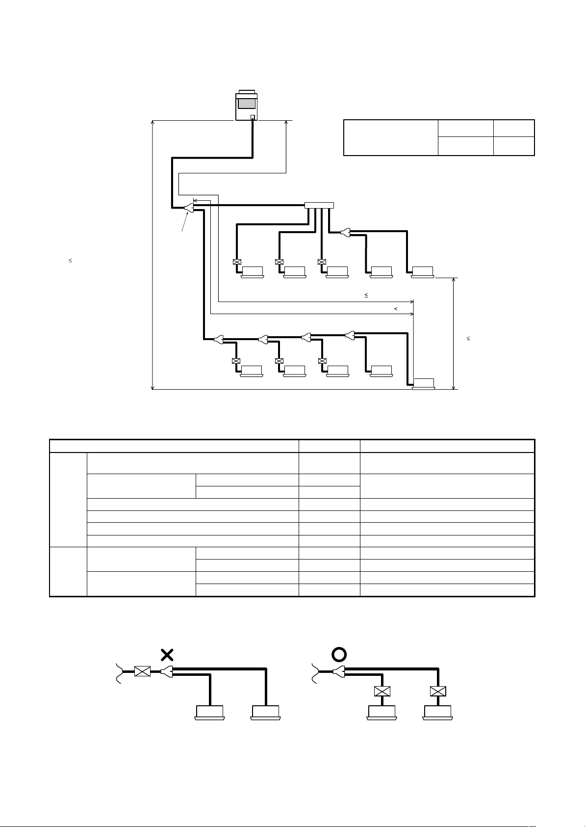
The concentration is as given below.
Total amount of refrigerant (kg)
Min. volume of the indoor unit installed room (m³)
≤ Concentration limit (kg/m³)
The concentration limit of R410A which is used in multi
air conditioners is 0.3kg/m³.
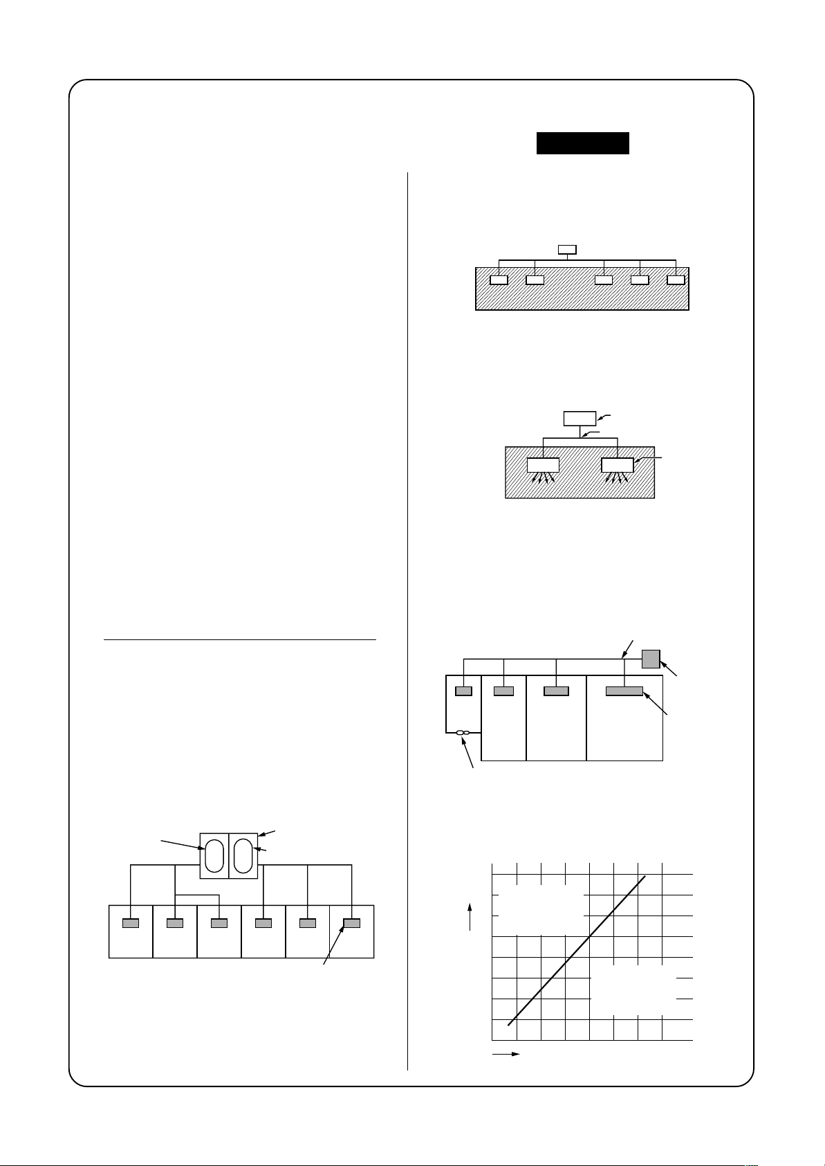
NOTE 1 :
If there are 2 or more refrigerating systems in a single
refrigerating device, the amounts of refrigerant should
be as charged in each independent device.
e.g., charged
amount (10kg)
Room A Room B Room C Room D Room E Room F
For the amount of charge in this example:
The possible amount of leaked refrigerant gas in
rooms A, B and C is 10kg.
The possible amount of leaked refrigerant gas in
rooms D, E and F is 15kg.
Outdoor unit
e.g.,
charged amount (15kg)
Indoor unit
Important
NOTE : 2
The standards for minimum room volume are as
follows.
(1) No partition (shaded portion)
(2) When there is an effective opening with the
adjacent room for ventilation of leaking refrigerant
gas (opening without a door, or an opening 0.15%
or larger than the respective floor spaces at the
top or bottom of the door).
Outdoor unit
Refrigerant piping
Indoor unit
(3) If an indoor unit is installed in each partitioned
room and the refrigerant tubing is interconnected,
the smallest room of course becomes the object.
But when a mechanical ventilation is installed
interlocked with a gas leakage detector in the
smallest room where the density limit is exceeded,
the volume of the next smallest room becomes the
object.
Refrigerant piping
Outdoor unit
Very
small
room
Small
room
Mechanical ventilation device - Gas leak detector
Medium
room
Large room
NOTE 3 :
The minimum indoor floor area compared with the
amount of refrigerant is roughly as follows:
(When the ceiling is 2.7m high)
40
Range below the
35
m²
density limit
of 0.3 kg/m³
30
(countermeasures
not needed)
25
20
15
10
5
Min. indoor floor area
0
10 20 30
Total amount of refrigerant
Range above
the density limit
of 0.3 kg/m³
(countermeasures
needed)
Indoor unit
kg
Page 3
NOTE
A direct current motor is adopted for indoor fan motor in the Concealed Duct Standard Type air conditioner.
Caused from its characteristics, a current limit works on the direct current motor. When replacing the highperformance filter or when opening the service panel, be sure to stop the fan. If an above action is executed
during the fan operation, the protectiv e control works to stop the unit operation, and the check code “P12”
may be appear. However it is not a trouble. When the desired operation has finished, be sure to reset the
system to clear “P12” error code using the electric leak breaker of the indoor unit. Then push the operation
ON/OFF button of the remote controller to return to the usual operation.
CONTENTS
1. SELECTING A LOCATION FOR INSTALLATION ..................................... 4
2. SAFETY NOTES......................................................................................... 8
3. CHECK POINTS......................................................................................... 9
4. KEY POINTS OF AIR CONDITIONER INSTALLATION .......................... 10
5. REFRIGERANT PIPE INSTALLATION .................................................... 11
6. INDOOR UNIT INSTALLATION................................................................ 41
7. FLOW SELECTOR UNIT INSTALLATION ............................................... 77
8. OUTDOOR UNIT INSTALLATION............................................................ 81
9. ELECTRIC WIRING .................................................................................. 87
10. INDOOR UNIT TERMINAL BOARD PLACEMENT AND WIRING ......... 102
11. DRAIN PIPE INSTALLATION................................................................. 107
12. ADJUSTMENT OF AIR DIRECTION...................................................... 115
13. APPLIED CONTROL.............................................................................. 119
14. ADDRESS SETUP.................................................................................. 123
15. TEST OPERATION ................................................................................. 136
16. SUPPORT FUNCTION IN TEST OPERATION ....................................... 143
17. TROUBLESHOOTING............................................................................ 165
18. AIR SPEED CHARACTERISTICS.......................................................... 170
19. FAN CHARACTERISTICS...................................................................... 175
Page 4
CAUTION New Refrigerant Air Conditioner Installation
• THIS AIR CONDITIONER ADOPTS THE NEW HFC REFRIGERANT (R410A) WHICH DOES
NOT DESTROY OZONE LAYER.
The characteristics of R410A refrigerant are ; easy to absorb water, oxidizing membrane or oil, and its
pressure is approx. 1.6 times higher than that of refrigerant R22. Accompanied with the new refrigerant,
refrigerating oil has also been changed. Therefore, during installation work, be sure that water, dust, former
refrigerant, or refrigerating oil does not enter the refrigerating cycle.
To prevent charging an incorrect refrigerant and refrigerating oil, the sizes of connecting sections of charging
port of the main unit and installation tools are charged from those for the conventional refrigerant.
Accordingly the exclusive tools are required for the new refrigerant (R410A).
For connecting pipes, use new and clean piping designed for R410A, and please care so that water or dust
does not enter. Moreover, do not use the existing piping because there are problems with pressureresistance force and impurity in it.
1. SELECTING A LOCATION FOR INSTALLATION
WARNING
Install the air conditioner certainly at a location to sufficiently withstand the weight.
If the strength is insufficient, the unit may fall down resulting in human injury.
Perform a specified installation work to guard against a great wind such as typhoon or an
earth quake.
An incomplete installation can cause accidents by the units failing and dropping.
The following models must be installed at height 2.5m or more from the floor.
(Concealed type duct type and cassette type air conditioners)
If you insert your hands or others directly into the unit while the air conditioner operates, it is dangerous
because you may contact with revolving fan or active electricity.
Installation Location Selection for Outdoor unit
Obtain permission from the customer to install the unit in a location that satisfies the
following requirements :
• A location that permits level installation of the unit.
• A location that provides enough space to service the unit safety
• A location where water draining from the unit will not pose a problem
Avoid installing in the following places.
• Place exposed to air with high salt content (seaside area), or place exposed to large quantities of sulfide
gas (hot spring). (Should the unit be used in these places, special protective measures are needed.)
• Place exposed to oil, vapor, oil smoke or corrosive gas.
• Place where organic solvent is used nearby.
• Place close to a machine generating high frequency.
• Place where the discharged air blows directly into the window of the neighboring house. (For outdoor unit)
• Place where noise of the outdoor unit is easily transmitted.
(When installing the air conditioner on the boundary with the neighbor, pay due attention to the level of noise.)
• Place with poor ventilation.
(Especially in Concealed duct type indoor unit, before air ducting work, check whether value of air volume,
static pressure and duct resistance are correct.)
4
Page 5
Equipments
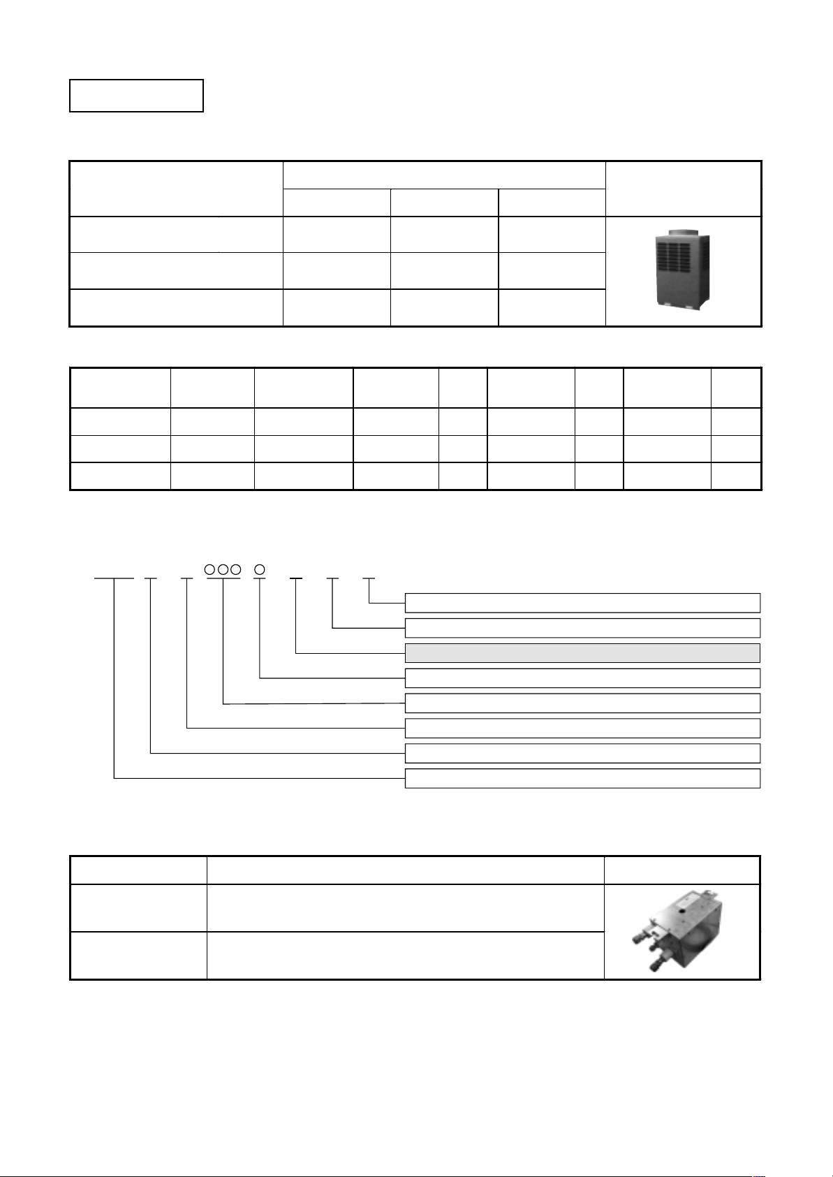
1. Outdoor units
Corresponding HP
Model name MMY- MAP0801FT8 MAP1001FT8 MAP1201FT8
Cooling capacity (kW) 22.4 28.0 33.5
Heating capacity (kW) 25.0 31.5 35.5
HP
(Capacity code)
8 HP ( 8) MAP0801HT8 1 MAP0801FT8 1
10 H P (10) MAP1001HT8 1 MAP1001FT8 1
12 H P (12) MAP1201HT8
Model name
MMY-
combined units
8 HP 10 HP 12 HP
No. of
1
Inverter 8HP
Inverter unit
MMY-
Used
Q’ty
Inverter 10HP
MMY-
Allocation atandard of model name
MMY– MAP T 8
F
Used
Q’ty
Appearance
Inverter 12HP
MMY-
MAP1201FT8
Used
Q’ty
1
Power supply specifications, 3Ø 380–415 V, 50Hz ....... 8
T : Capacity variable unit
F : Heat recovery
Development series No.
Capacity rank HP x 10
New refrigerant R410A
M : Single module unit, No mark : Combined Model name
Modular Multi
2. FS units (Flow selector units)
Model name Inverter unit Appearance
RBM-Y1121FE Capacity rank f or indoor unit : Type 007 to 030
RBM-Y1801FE Capacity rank f or indoor unit : Type 036 to 056
∗ Accessory part : Connection cable kit (RBC-CBK15FE), up to 15m.
5
Page 6
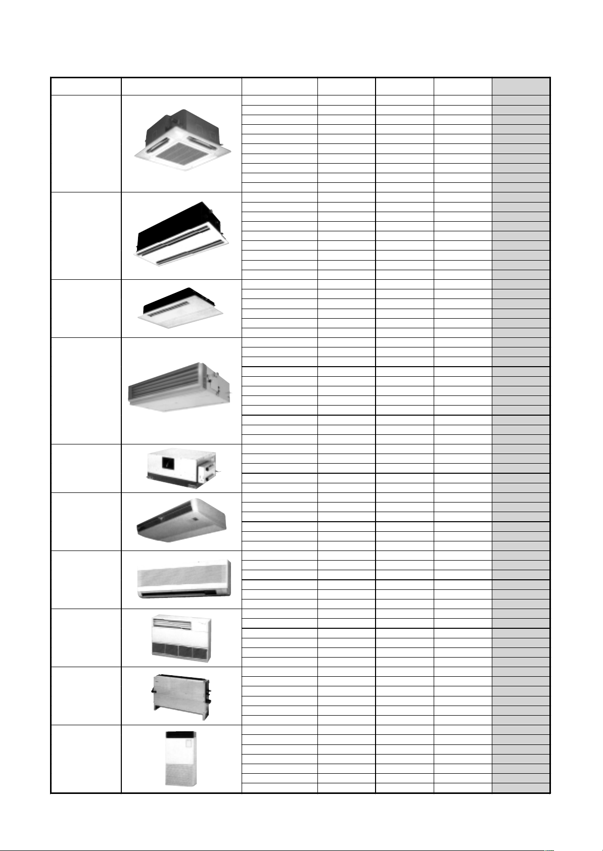
3. Indoor units
Type Appearance Model name Capacity rank Capaci t y code
009 type 1 2.8
012 type 1.25 3.6
015 type 1.7 4.5
018 type 2 5.6
024 type 2.5 7.1
027 type 3 8.0
030 type 3.2 9.0
036 type 4 11.2
048 type 5 14.0
056 type 6 16.0
007 type 0.8 2.2
009 type 1 2.8
012 type 1.25 3.6
015 type 1.7 4.5
018 type 2 5.6
024 type 2.5 7.1
027 type 3 8.0
030 type 3.2 9.0
1)
048 type 5 14.0 16.0
007 type 0.8 2.2
009 type 1 2.8
012 type 1.25 3.6
015 type 1.7 4.5
018 type 2 5.6
024 type 2.5 7.1
007 type 0.8 2.2
009 type 1 2.8
012 type 1.25 3.6
015 type 1.7 4.5
018 type 2 5.6
024 type 2.5 7.1
027 type 3 8.0
030 type 3.2 9.0
036 type 4 11.2
048 type 5 14.0
056 type 6 16.0
018 type 2 5.6
024 type 2.5 7.1
027 type 3 8.0
036 type 4 11.2
048 type 5 14.0
015 type 1.7 4.5
018 type 2 5.6
024 type 2.5 7.1
027 type 3 8.0
036 type 4 11.2
048 type 5 14.0
007 type 0.8 2.2
009 type 1 2.8
012 type 1.25 3.6
015 type 1.7 4.5
018 type 2 5.6
024 type 2.5 7.1
007 type 0.8 2.2
009 type 1 2.8
012 type 1.25 3.6
015 type 1.7 4.5
018 type 2 5.6
024 type 2.5 7.1
007 type 0.8 2.2
009 type 1 2.8
012 type 1.25 3.6
015 type 1.7 4.5
018 type 2 5.6
024 type 2.5 7.1
015 type 1.7 4.5
018 type 2 5.6
024 type 2.5 7.1
027 type 3 8.0
036 type 4 11.2
048 type 5 14.0
056 type 6 16.0
4-way Air Discharge
Cassette Type
2-way Air Discharge
Cassette Type
1-way Air Discharge
Cassette Type
Concealed Duct
Standard Type
Concealed Duct
High Static
Pressure Type
Under Ceiling Type
High Wall Type
Floor Standing
Cabinet Type
Floor Standing
Concealed Type
Floor Standing Ty pe
MMU-AP0091H
MMU-AP0121H
MMU-AP0151H
MMU-AP0181H
MMU-AP0241H
MMU-AP0271H
MMU-AP0301H
MMU-AP0361H
MMU-AP0481H
MMU-AP0561H
MMU-AP0071WH
MMU-AP0091WH
MMU-AP0121WH
MMU-AP0151WH
MMU-AP0181WH
MMU-AP0241WH
MMU-AP0271WH
MMU-AP0301WH
MMU-AP0481WH*
MMU-AP0071YH
MMU-AP0091YH
MMU-AP0121YH
MMU-AP0151SH
MMU-AP0181SH
MMU-AP0241SH
MMD-AP0071BH
MMD-AP0091BH
MMD-AP0121BH
MMD-AP0151BH
MMD-AP0181BH
MMD-AP0241BH
MMD-AP0271BH
MMD-AP0301BH
MMD-AP0361BH
MMD-AP0481BH
MMD-AP0561BH
MMD-AP0181H
MMD-AP0241H
MMD-AP0271H
MMD-AP0361H
MMD-AP0481H
MMC-AP0151H
MMC-AP0181H
MMC-AP0241H
MMC-AP0271H
MMC-AP0361H
MMC-AP0481H
MMK-AP0071H
MMK-AP0091H
MMK-AP0121H
MMK-AP0151H
MMK-AP0181H
MMK-AP0241H
MML-AP0071H
MML-AP0091H
MML-AP0121H
MML-AP0151H
MML-AP0181H
MML-AP0241H
MML-AP0071BH
MML-AP0091BH
MML-AP0121BH
MML-AP0151BH
MML-AP0181BH
MML-AP0241BH
MMF-AP0151H
MMF-AP0181H
MMF-AP0241H
MMF-AP0271H
MMF-AP0361H
MMF-AP0481H
MMF-AP0561H
*1) China only
Cooling
capacity (kW)
Heating
capacity (kW)
3.2
4.0
5.0
6.3
8.0
9.0
10.0
12.5
16.0
18.0
2.5
3.2
4.0
5.0
6.3
8.0
9.0
10.0
2.5
3.2
4.0
5.0
6.3
8.0
2.5
3.2
4.0
5.0
6.3
8.0
9.0
10.0
12.5
16.0
18.0
6.3
8.0
9.0
12.5
16.0
5.0
6.3
8.0
9.0
12.5
16.0
2.5
3.2
4.0
5.0
6.3
8.0
2.5
3.2
4.0
5.0
6.3
8.0
2.5
3.2
4.0
5.0
6.3
8.0
5.0
6.3
8.0
9.0
12.5
16.0
18.0
6
Page 7
Tools
Required Tools
The used refrigerating oil is changed, and mixing of oil may cause a trouble such as generation of sludge,
clogging of capillary, etc. Accordingly, the tools to be used are classified into the following three types.
(1) Tools exclusive for R410A (Those which cannot be used for conventional refrigerant (R22))
(2) Tools exclusive for R410A, but can be also used for conventional refrigerant (R22)
(3) Tools commonly used for R410A and for conventional refrigerant (R22)
The table below shows the tools exclusive for R410A and their interchangeability.
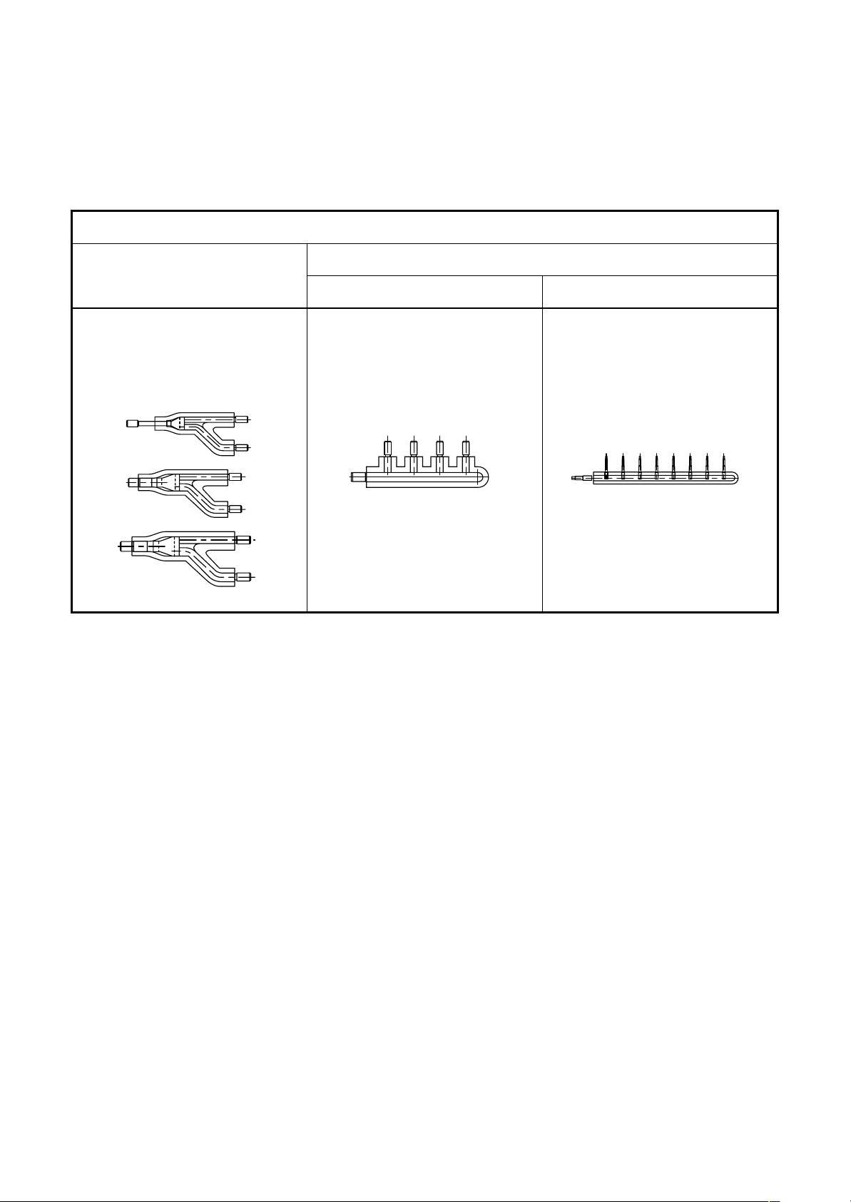
Tools exclusive for R410A (The following tools for R410A are required.)
Tools whose specifications are changed for R410A and their interchangeability
Conventional air
conditioner installation
Whether new equipment
can be used with
conventional refrigerant
¡
*(Note 1)
×
×
¡
¡
×
¡
×
No.
Used tool
Flare tool
Copper pipe gauge for
adjusting projection
margin
Torque wrench
Gauge manifold
Charge hose
Vacuum pump adapter
Electronic balance for
refrigerant charging
Refrigerant cylinder
Leakage detector
Charging cylinder
Usage
Pipe flaring
Flaring by conventional
flare tool
Connection of flare nut
Evacuating, refrigerant
charge, run check, etc.
Vacuum evacuating
Refrigerant charge
Refrigerant charge
Gas leakage check
Refrigerant charge
air conditioner installation
Existence of
new equipment
for R410A
Yes
Yes
Yes
Yes
Yes
Yes
Yes
Yes
(Note 2)
R410A
Whether conventional
equipment can be
used
*(Note 1)
*(Note 1)
×
×
×
Yes
×
×
×
(Note 1) When flaring is carried out for R410A using the conventional flare tools, adjustment of projection
margin is necessary. For this adjustment, a copper pipe gauge, etc. are necessary.
(Note 2) Charging cylinder for R410A is being currently developed.
General tools (Conventional tools can be used.)
In addition to the above exclusive tools, the following equipments which serve also for R22 are necessary
as the general tools.
(1) Vacuum pump
Use vacuum pump by
attaching vacuum pump adapter.
(2) Torque wrench
(3) Pipe cutter
(4) Reamer
(5) Pipe bender
(6) Level vial
(7) Screwdriver (+, –)
(8) Spanner or Monkey wrench
(9) Hole core drill
(10) Hexagon wrench
(Opposite side 4mm)
(11) Tape measure
(12) Metal saw
Also prepare the following equipments for other installation method and run check.
(1) Clamp meter
(2) Thermometer
(3) Insulation resistance tester
(4) Electroscope
7
Page 8
2. SAFETY NOTES
• Ensure that all Local, National and International regulations are satisfied.
• Read this “SAFETY NOTES” carefully before Installation.
• The precautions described below include the important items regarding safety. Observe them without fail.
• After the installation work, perform a trial operation to check for any problem.
Follow the Owner’s Manual to explain how to use and maintain the unit to the customer.
• Turn off the main power supply switch (or breaker) before the unit maintenance.
• Ask the customer to keep the Installation Manual together with the Owner’s Manual.
WARNING
• Ask an authorized dealer or qualified installation professional to install/maintain the air
conditioner.
Inappropriate installation may result in water leakage, electric shock or fire.
• Turn off the main power supply switch or breaker before attempting any electrical work.
Make sure all power switches are off. Failure to do so may cause electric shock.
• Connect the connecting wire correctly.
If the connecting wire is connected in a wrong way, electric parts may be damaged.
• When moving the air conditioner for the installation into another place, be very careful not to enter
any gaseous matter other than the specified refrigerant into the refrigeration cycle.
If air or any other gas is mixed in the refrigerant, the gas pressure in the refrigeration cycle becomes abnormally
high and it as a result causes pipe burst and injuries on persons.
• Do not modify this unit by removing any of the safety guards or by by-passing any of the safety
interlock switches.
• Exposure of unit to water or other moisture before installation may cause a short-circuit of
electrical parts.
Do not store it in a wet basement or expose to rain or water.
• After unpacking the unit, examine it carefully if there are possible damage.
• Do not install in a place that might increase the vibration of the unit.
• To avoid personal injury (with sharp edges), be careful when handling parts.
• Perform installation work properly according to the Installation Manual.
Inappropriate installation may result in water leakage, electric shock or fire.
• When the air conditioner is installed in a small room, provide appropriate measures to ensure that
the concentration of refrigerant leakage occur in the room does not exceed the critical level.
• Install the air conditioner securely in a location where the base can sustain the weight adequately.
• Perform the specified installation work to guard against an earthquake.
If the air conditioner is not installed appropriately, accidents may occur due to the falling unit.
• If refrigerant gas has leaked during the installation work, ventilate the room immediately.
If the leaked refrigerant gas comes in contact with fire, noxious gas may generate.
• After the installation work, confirm that refrigerant gas does not leak.
If refrigerant gas leaks into the room and flows near a fire source, such as a cooking range, noxious gas might
generate.
• Electrical work must be performed by a qualified electrician in accordance with the Installation
Manual. Make sure the air conditioner uses an exclusive power supply.
An insufficient power supply capacity or inappropriate installation may cause fire.
• Use the specified wires for wiring connect the terminals securely fix. To prevent external forces
applied to the terminals from affecting the terminals.
• Conform to the regulations of the local electric company when wiring the power supply.
Inappropriate grounding may cause electric shock.
• Do not install the air conditioner in a location subject to a risk of exposure to a combustible gas.
If a combustible gas leaks, and stays around the unit, a fire may occur.
8
Page 9
3. CHECK POINTS
Check before operation
• Turn on the main power switch 12 hours or more before starting the operation.
• Check whether earth wire is disconnected or out of place.
• Check that air filter is installed to the indoor unit.
Heating capacity
• For heating operation, a heat pump type which absorbs the outdoor heat and deliver the heat in the room is adopted.
If the outdoor temperature lowers, the heating capacity decreases.
• When the outdoor temperature is low, common use with other heating devices is recommended.
Defrost operation in heating operation
• If frost is found on the outdoor unit during heating operation, the defrost operation starts automatically (for approx. 2 to 10
minutes) so as to increase the heating effect.
• During defrost operation, the fans of both indoor and outdoor units stop.
Protection for 3 minutes
• The outdoor unit does not operate for approx. 3 minutes after air conditioner has been immediately restarted after stop, or
power switch has been turned on. This is to protect the system.
Main power failure
• If a power failure occurs during operation, all operations stop.
• When the power is turned on after power failure, the operation lamp of the remote controller flashes to notify.
• When restarting the operation, push ON/OFF button again.
Fan rotation of stopped unit
• While other indoor units operate, the fan on indoor units on “stand-by” rotates to protect the machine once per approx. 1
hour for several minutes.
Protective device (High pressure switch)
The high pressure switch operate the air conditioner automatically stops when excessive load is applied to the air
conditioner. If the protective device works, the operation lamp keeps lit but the operation stops.
When the protective device works, “CHECK” characters in the remote controller display section flash.
The protective device may work in the following cases.
Cooling
• When air inlet or outlet of the outdoor unit is closed.
• When strong wind blows continuously against air outlet of the outdoor unit.
Heating
• When much dust or dirt is excessively adhered to air filter of the indoor unit.
• When air outlet of the indoor unit is blocked.
NOTE
If the protective device works, turn off the main power switch, remove the cause, and then restart the operation.
Cooling/ heating operation of Multi system air conditioner
• When COOL or HEAT mode is fixed by the manager of the air conditioner, other operation than the set mode is
unavailable. If other operation than the set mode has been performed, [
operation part goes on and the operation stops.
Operating temperature of Super HRM
• When outdoor temperature goes out of specified range, “ or ” mark is indicated on the remote controller display and
required operation will stop. “
[Notice]
• This indication is not failure.
• When outdoor temperature goes back to specified range, “
• Operation stops because concurrent operation can not be kept in the condition of out of specification for Super HRM.
(Outdoor temp. (DB) < –5°C : Cooling, > 21°C : Heating)
• Do not use “Super HRM” for other than personal usage where the ambient temperature may go down below –5°C.
(For example, OA equipment/Electric device/Food/Animals and plants/Art object)
& ” : When heating operation. “ ” : When cooling operation.
or ” disappear and start normal operation.
Characteristics of heating operation
• Air does not blow out immediately after start of the operation. When the indoor heat exchanger has been heated after 3 to
5 minutes passed (differs according to temperature of indoor/outdoor temperature), hot air starts blowing.
• During operation, the outdoor unit may stop when outdoor temperature becomes high.
• When other indoor unit performs heating operation during fan operation, fan operation may be stopped temporarily to
prevent discharge of hot air.
9
PRE-HEAT] or [ Operation ready] on the
Page 10

4.
g
KEY POINTS OF AIR CONDITIONER INSTALLATION
In order to prevent problems before they arise, carefully read (1) the Installation Manual provided with the
equipment, and (2) the Owner’s Manual before installing the air conditioner.
4-1. Flow of Air Conditioner Installation Work
[Step] [Key Points]
(Prior to Installation)
Determination of extent of installation work
Drafting of diagrams
(Installation)
Sleeve/insert installation
Indoor unit and flow selector unit installation
Refrigerant pipe installation
(to outdoor outlet)
Drain pipe installation
Duct installation
Insulation work
Clearly determine the extent of the installation work.
Draft :
• Control wiring system diagram
• Refrigerant line system diagram
• Power wiring system diagram
Pay careful attention to the downward slope of the drain pipe.
Be sure to check the name of the model in order to avoid any
installation mistakes. If the model has an installation pattern, attach
the pattern to the ceiling to mark the position of the ceiling openings
and to keep dust away.
Make sure that the pipe system is dry, clean, and airtight.
When brazing pipes, blow out the system with nitrogen gas.
Do not forget the system indications.
Pipes should have downward slope (of at least 1/100).
Make sure the duct is lar
Be careful not to make any errors in the external static pressure
calculations.
Be especially careful to close off all gaps where connections are m ade
to the indoor unit, and at joints in the branching kit. Do not forget the
drain pipes.
e enough to carry the desired volume of air.
Use two-core shielded wires for the control wires, and use separate
(control wires and power wires)
Electrical work
Various s witc h setting s
Outdoor unit base installation
Outdoor unit installation
Outside circulation, refrigerant pipe instal lation
Gas-leak test
Vacuum suction
Addition of refrigerant
Ceiling panel installation
Test operation and adjustment
Owner’s Manual transfer
power supplies for the indoor and outdoor units. For connecting the
flow selector unit, be sure to use the attached cable or connection
cable kit sold separately.
Set the switches correctly, as indicated in the control wiring system
diagram.
Make sure that the base is level.
Provide for adequate air flow and service space around the outdoor
unit. Indicate the system names clearly.
From outside outlet to outdoor unit.
In the final test, the system must be pressurized at 3.73MPa
(38kg/cm²G) for 24 hours with no decrease in pressure.
Use a vacuum pump with reverse flaw prevention adaptor with a large
output volume and that can achieve a high level of vacuum.
Record the amount of refrigerant that was added to the system on
both the outdoor unit and on the pre-test operation checklist.
Make sure that the ceiling panel is attached to the ceiling material
tightly, with no gaps.
Operate the indoor units one by one, making sure that all wiring and
pipes are connected correctly, and fill out the checklist.
Explain how to operate the system clearly and concisely.
The procedure described above presents only the general sequence of steps; the sequence of steps may have
to be altered according to the circumstances of any specific installation job.
10
Page 11
5. REFRIGERANT PIPE INSTALLATION
5-1. Work Procedure
Indoor unit
installation
Sizing
the pipes
Preliminary
installation
Nitrogen gas blow
Flaring
Flushing
Brazing
Leak test
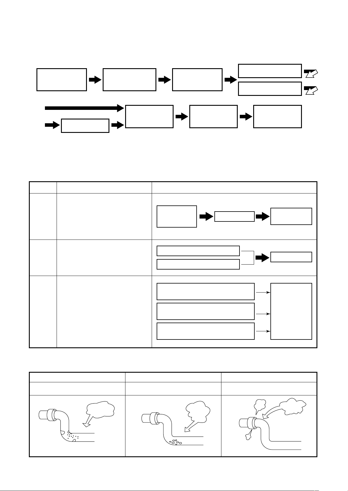
5-2. Three Principles of Refrigerant Pipes
<Observe the three principles of refrigerant pipes>
Causes of Problems Preventing Problems
• Moisture (in the form of
Dry
Clean
rainwater or water used during
installation, for example)
getting inside of the pipes
• Moisture from condensation
forming or seeping into the pipes
• Oxidation inside pipes during
brazing
• Dirt, dust, or foreign matter
getting inside pipes
Careful
handling
of pipes
Nitrogen gas blow
Careful handling of pipes
Flushing
Vacuum
suction
Vacuum
suction
Flushing
Use of suitable materials
(copper pipes, solder, etc.)
Air-
tight
• Poor brazing
• Poor flaring
Perform basic work
of brazing carefully
Perform basic work
of flaring carefully
<Three principles of refrigerant pipes>
Dry
Make sure there is no moisture
inside of the pipes
Moisture
Make sure there is no dirt
Clean Airtight
Make sure the refrigerant
inside of the pipes
Dirt
Not good Not good Not good
Leak test
does not leak
Leak
11
Page 12
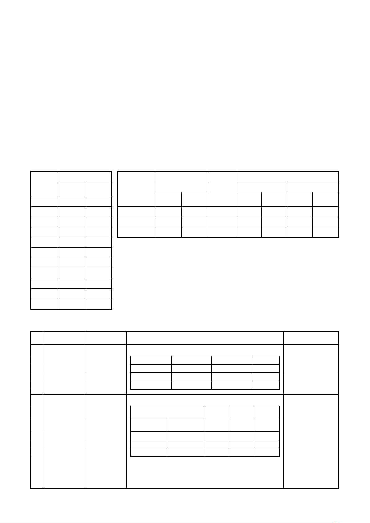
5-3. Selecting the Refrigerant Line Material
q
q
• Refrigerant pipes
• Material: Phosphoric deoxidized seam-less pipe
• Capacity code of outdoor unit / indoor unit
• For each indoor unit, the capacity code is determined for every capacity rank.
• For each outdoor unit, the capacity code is determined for every capacity rank. The Max. number of the
connectable indoor units and the total capacity code value of the indoor units are also determined.
Against the capacity code of the outdoor unit, the total capacity codes of the connectable indoor units differ
according to the height difference between indoor units.
• When the height difference between indoor units is 15m or less : Up to 135%* of capacity code of outdoor unit
(* For 12HP system, up to 120%.)
• When the height difference between indoor units is 15m or more : Up to 105% of capacity code of outdoor unit
Table 1 Table 2
Indoor unit
capacity rank
007 type 0.8 2.2
009 type 1 2.8
012 type 1.25 3.6
015 type 1.7 4.5
018 type 2 5.6
024 type 2.5 7.1
027 type 3 8
030 type 3.2 9
036 type 4 11.2
048 type 5 14
056 type 6 16
Capacity code
E
uivalent toHPEquivalent to
capacity
Outdoor unit
model name
MMY-MAP0801FT8 8 22.4 13 5.6 15.7 10.8 30.2
MMY-MAP1001FT8 10 28.0 16 7.0 19.6 13.5 37.8
MMY-MAP1201FT8 12 33.5 16 8.4 23.5 14.4 40.3
Capacity code
E
uivalent toHPEquivalent to
capacity
No. of
indoor units
Total capacity code of connectable indoor units
Min Max.
Equivalent
to HP
Equivalent
to capacity
Equivalent
to HP
Table 3
No. Piping parts Name Selection of pipe size Remarks
Outdoor unit
↓
1st branching joint
Outdoor unit
main pipe
1) Connecting pipe outdoor unit
Model name Suction gas side Discharge gas side Liquid side
MMY-MAP0801FT8 Ø22.2 Ø19.1 Ø12.7
MMY-MAP1001 FT8 Ø22.2 Ø19.1 Ø12.7
MMY-MAP1201 FT8 Ø28.6 Ø19.1 Ø12.7
Same to connecting
pipe size of outdoor unit
Equivalent
to capacity
Branching section
Branching pipe
2) Pipe size betw een branching sections
Pipe size differs based
on total capacity code
↓
Branching section
Total capacity codes of indoor units
at downstream side
Equivalent to
capacity
Below 18.0 Below 6.4 Ø15.9 Ø12.7 Ø9.5
18.0 to below 34.0 6.4 to below 12.2 Ø22.2 Ø19.1 Ø12.7
34.0 to below 45.5 12.2 to below 16.2 Ø28.6 Ø22.2 Ø15.9
∗
If exceeding the main pipe size, decide the size same to main pipe
Equivalent
to HP
Suction
gas side
Discharge
gas side
Liquid side
value of indoor units at
downstream side.
If the total value
exceeds the capacity
code of the outdoor unit,
apply capacity code of
the outdoor unit.
(See tables 1 and 2.)
size.
∗
When two pipes are used for the circuits exclusive to cooling, use
pipes at liquid and suction gas sides.
12
Page 13
No. Piping parts Name Selection of pipe size
g
g
End branching
section
↓
Flow selector unit
Branching section
or flow selector
unit
↓
Indoor unit
Branching section
Connecting pipe
of flow selector
unit
Connecting pipe
of indoor unit
Branchin
header
of Y-shape
branching joint
3) Pipe size between end branching section and flow selector unit
To tal capac ity codes of indoo r units
at downstream side
Equivale nt to capacity Equivalent to HP
Below 4.5 Below 1.7 Ø12.7 Ø9.5 Ø6.4
4.5 to below 18.0 1.7 to below 6.4 Ø15.9 Ø12.7 Ø9.5
Suction
gas side
Discharge
gas side
Liquid side
4) Connecting pipe size of indoor unit
Capacity rank Gas side Liqu id side
007 to 012 type
∗
When pipe len
Real length: Below 15m Ø9.5
Real length: Over 15m
015 to 018 type Ø12.7
024 to 056 type Ø15.9 Ø9.5
∗
Ø12.7
Ø6.4
th between the end branching section and cooling-only indoor unit exceeds 15m,
decide pipe size at gas side to the bigger one with Ø12.7.
5) Selection of branching joint/header
To tal capac ity codes of indoo r units Model name RBM-
Equivalent to
capacity
Y-shape branching joint
∗
1, 2
Branching header
∗
1, 2, 3
∗
1 For branching pipe of the 1st branching section, select one by the outdoor unit capacity code.
∗
2 When total capacity codes of indoor units exceed capacity code of outdoor unit, select one by
Below 18.0 Below 6.4 BY53FE BY53E
18.0 to below 40.0 6.4 to below 14.2 BY103FE BY103E
Below 40.0 Below 14.2 HY1043 FE HY1043E
Below 40.0 Below 14.2 HY1083 FE HY1083E
Equivalent to HP
For 3
pipes piping
For 2
pipes piping
capacity code of outdoor unit.
∗
3 1 line after header branching is connectable up to total maximum capacity codes 6.0
(Equivalent to HP).
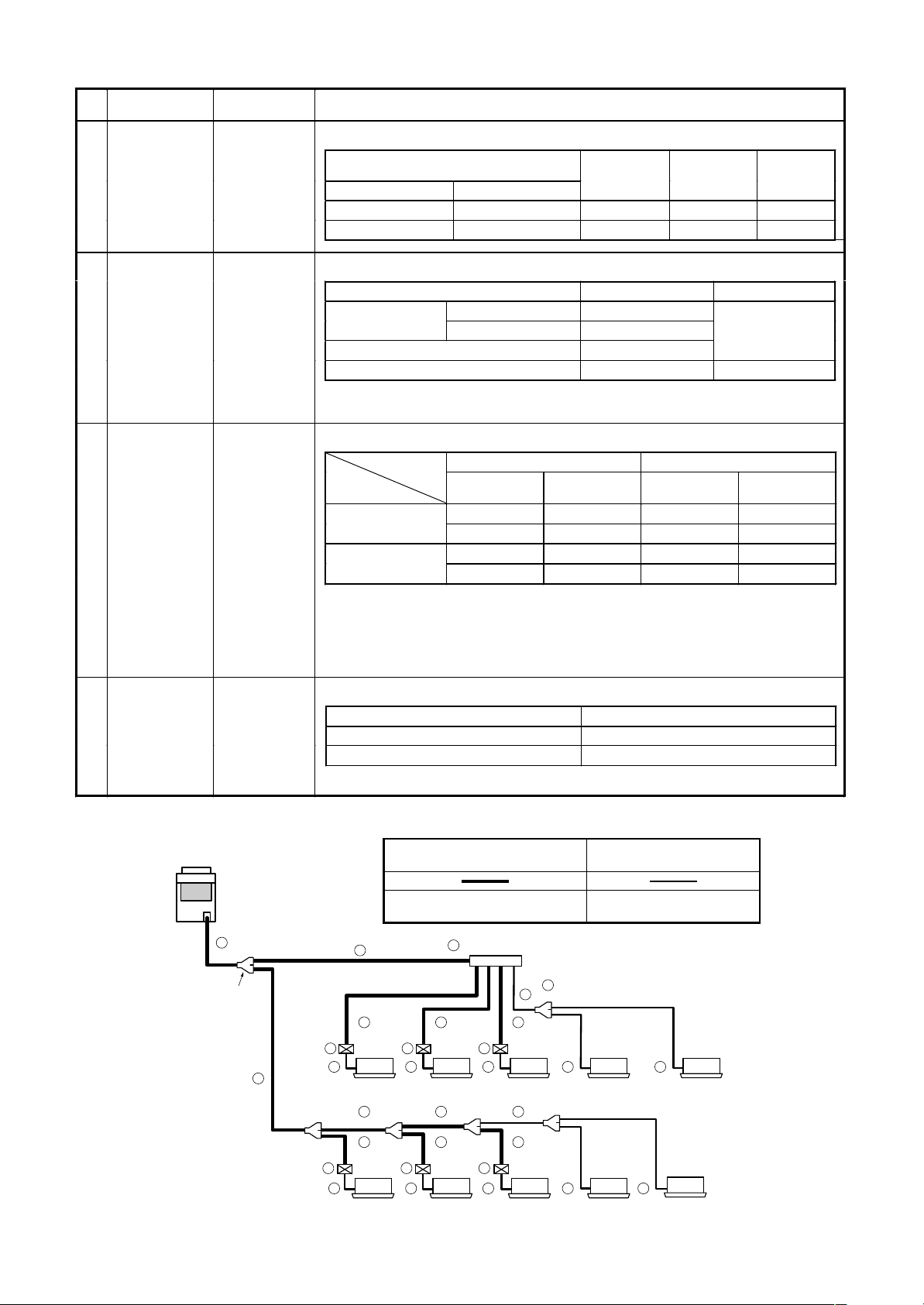
Branching Flow selector unit
Outdoor unit
1 Main piping
1st branching
section
6) Selection of flow selector unit
Model name Capacity rank of connectable indoor unit
RBM-Y1121FE 007 to 030 type
RBM-Y1801FE 036 to 056 type
∗
Confirm also Installation Manual of flow selector unit.
(Liquld,discharge gas,suction gas)
3 piping
Outdoor unit to FS unit
2
3
6 6 6
FS unit
2
4 4 4 4 4
Indoor unit
2 2 2
5 Header branching
3
5 Y-shape branching joint
2
3
FS unit to indoor unit
Branching section indoor unit
< Cooling only > < Cooling only >
2 piping
(Liquld, gas pipe)
3 3 3
6 6 6
FS unit
4 4 4 4 4
Indoor unit
< Cooling only > < Cooling only >
13
Page 14
5-4. Allowable Length/Height Difference of Refrigerant Piping
Height difference between outdoor
and indoor units
H1
50m
1st branching
section
Main
piping
Outdoor unit
L1
• System restrictions
∗ For 12HP system, up to 120%
Branching
Branching piping L2
Connecting piping of indoor unit
L3
FS unit
a
ghi j
Indoor unit
Equivalent length corresponded to farthest piping L 125m
Equivalent length corresponded to farthest piping after 1st branching Li 50m
L4 L5 L6
def
lmn
header
L7
bc
FS unit
Max. capacity of
combined indoor unit
k
< Cooling only >
o
< Cooling only >
< Cooling only >
p
< Cooling only >
H2 ≤ 15m
H2 > 15m
Height difference between
indoor units
35m
H2
135%
105%
• Allowable length and height difference of refrigerant piping
Allowable value Piping section
Total extension of pipe (Liquid pipe, real length) 250 m
Pipe
Length
Height
difference
1 The farthest indoor unit from the 1st Branch to be named as (p).
*
2 Attached connection cable can be used up to 5 m in pipe length between indoor and FS unit. When the pipe length
*
Farthest piping length L (*1)
Max. equivalent length of main piping 85 m L1
Equivalent length of farthest piping from 1st branching Li (*1) 50 m L3 + L4 + L5 + L6 + p
Max. real length of indoor unit connecting piping 30 m a + g, b + h, c + l, d + l, e + m, f + n, j, k, o, p
Max. real length between FS unit and indoor unit (
Height between indoor
and outdoor units H1
Height between indoor units H2
Real length 100 m
Equivalent length 125 m
2) 15 m g, h, i, l, m, n
Upper outdoor unit 50 m ——
Lower outdoor unit 30 m ——
Upper outdoor unit 35 m ——
Lower outdoor unit 15 m ——
*
between indoor and FS unit exceeds 5 m, be sure to use the connection cable kit (RBC-CBK15FE). (Sold separately)
FS unit
L1 + L2 + L3 + L4+ L5 + L6 + L7 + a + b + c +
d + e + f + g + h + i + j + k + l + m + n + o + p
L1 + L3 + L4 + L5 + L6 + p
FS unit
Indoor unit Indoor unit
[NOTE] :
Don’t connect two or more indoor units to one FS unit. Arrange one indoor unit and one FS unit set to 1 by 1.
14
Page 15
• Brazed couplings and special branches
• Use suitable parts for typical elbow couplings and socket couplings.
(Consider the size, material, thickness, etc.)
• Special branches
Use deoxidized parts sold separately.
Branching at indoor unit side
Branch header
Branching jo int
4 branching 8 branching
RBM-BY53E
RBM-BY103E
RBM-BY53FE
RBM-BY103FE
RBM-HY1043E
RBM-HY1043FE
RBM-HY1083E
RBM-HY1083FE
• Solder
Because only “copper-to-copper” connections are made in the multi type air conditioning system, use the hard
solder “phosphor copper solder.”
15
Page 16
5-5. Careful Handling
Careful handling is the most important step in preventing moisture, dirt, and dust from getting inside of the pipes.
Moisture in pipes has caused major problems in numerous instances in the past. Therefore, it is important to be
as careful as possible in order to prevent problems before they occur.
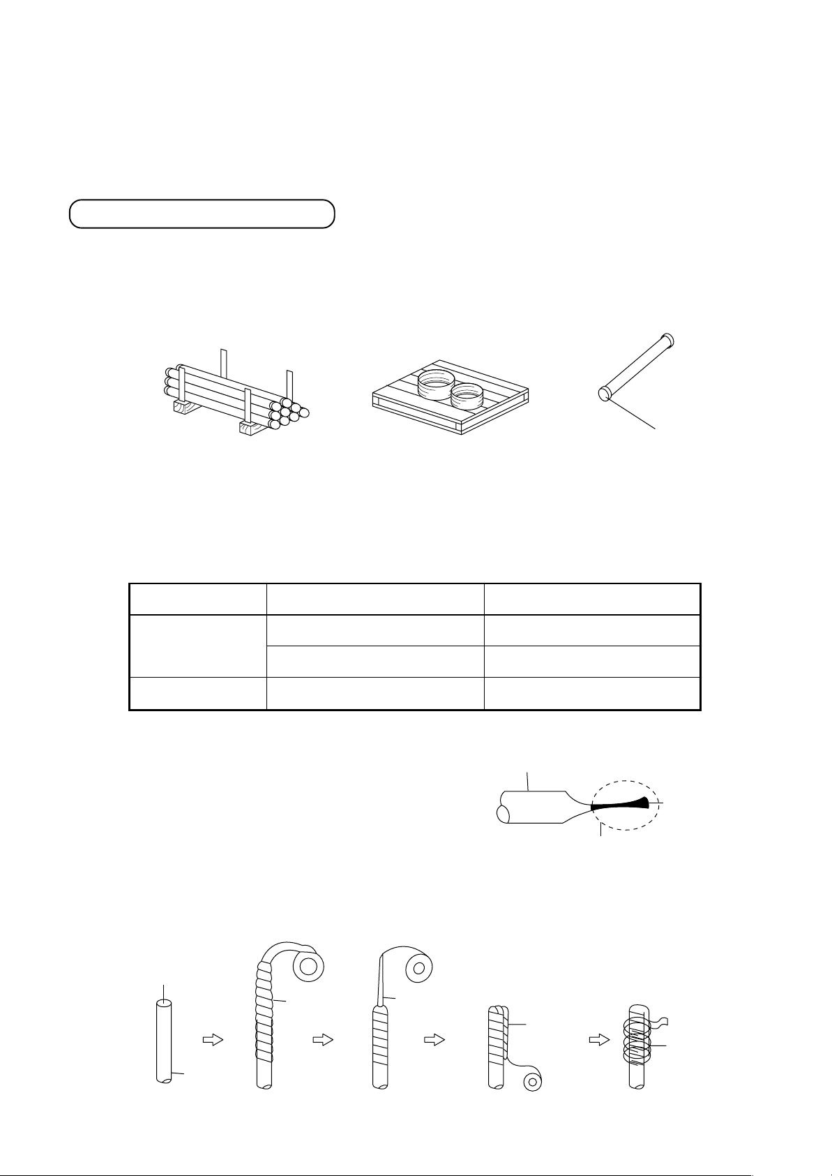
Pipe delivery and storage
When pipes are delivered, care should be taken to prevent it from becoming bent or deformed, and the ends of
the pipes should be capped in order to prevent dirt, mud, rain, etc., from getting inside. Build a wooden frame to
hold the pipes securely, and store the pipes in the specified location.
Delivery of copper pipes without caps to a work site is not acceptable.
Cap
Frame for careful handling
and to prevent rolling
Careful handling on a pallet
Pipe caps
The ends of all pipes must be sealed. The most reliable method is the “pinch method,” but the taping method
can be selected in some circumstances.
Location
Outdoors
Indoors
Time for installation
One month or more
Less than one month
Does not matter
Careful handling method
Pinch method
Pinch or taping method
Pinch or taping method
n Pinch method
Pinch the end of the copper pipe closed,
and braze any opening closed.
Copper pipe
Solder
Braze here
n Taping method
Cover the end of the copper pipe with vinyl tape.
[Taping method]
Opening
Copper
pipe
Vinyl tape
Flatten
Fold over
Tape again
16
Page 17
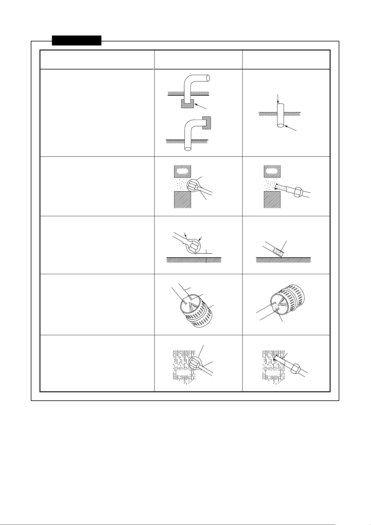
CAUTIONS
1) Do not allow dirt or moisture
inside of the pipes.
• Keep the open ends of all pipes
capped until all pipes have been
connected.
• Pipe openings should face
horizontally or downwards if at all
possible.
GOOD NOT GOOD
Dirt and moisture get inside
Cap
Pipe
2) When passing a pipe through an
opening in a wall, always keep
the end of the pipe capped.
3) Do not place pipes directly on
the ground. Do not scrape pipes
on the ground.
4) When deflashing (removing
burrs from) a pipe, point the
opening downwards so that no
scraps fall inside of the pipe.
5) When installing pipes on a rainy
day, always keep the ends of the
pipes capped.
Cap or
Wall
plastic bag
Rubber band
Rubber
Cap or
band
plastic bag
Do not allow
pipe to touch
ground
Ground Ground
Pipe
Burrs
Deflasher
Cap or
plastic bag
Rubber
band
Rain
Wall
Dirt gets inside of pipe
Scraps get inside of pipe
Rain
Particles of
the wall get
inside the pipe
Rain gets
inside of pipe
17
Page 18
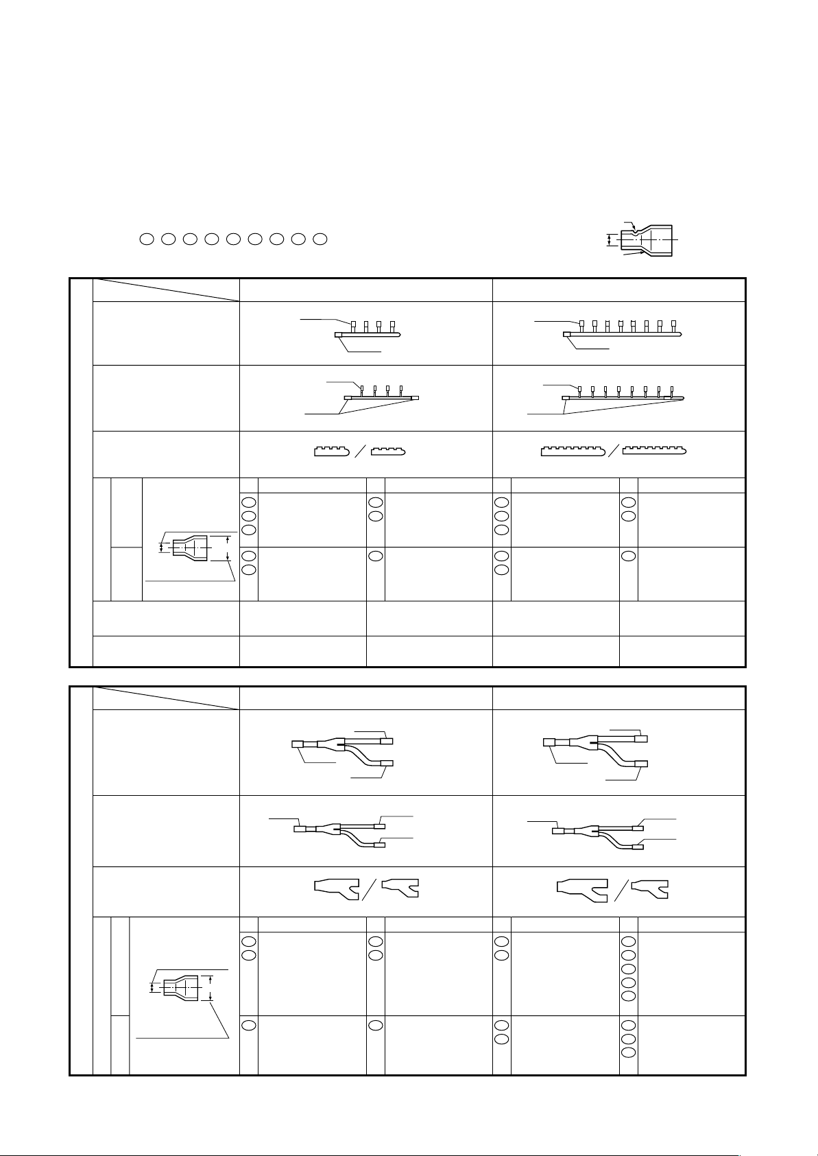
5-6. Parts of Branching Header/Joint
Branching Header : RBM-HY1043E / HY1083E
Branching Joint : RBM-BY53E / BY103E
• Check the following parts in the package.
• For piping material and size of the refrigerant pipes, refer to the Installation Manual of the Air Conditioner.
NOTE : 1. All dimensions are in millimeters. In the following tables, ( ) indicates diameter of the indicated position, and
others indicate diameter of the connecting pipe.
2. Please connect pipe to the side with a projection of the socket.
( 51 , 52 , 54 , 58 , 59 , 61 , 62 , 70 , 89 : without projection)
Diameter of the
connecting pipe
projection
socket
NAME
MODEL
Branching header
gas side
Branching header
liquid side
Heat insulator
(gas side/liquid side)
side
diameter of the
connected pipe
Gas
Branching Header
Socket
Outlet sealed pipe at gas side
Header sealed pipe at liquid side
Outlet sealed pipe at liquid side
external diameter
of socket
side
Liquid
No.
Ø15.9 x (Ø22.2) 1pc
14
Ø19.1 x (Ø22.2) 1pc
18
Ø28.6 x (Ø22.2) 1pc
70
( )
06
Ø12.7 x (Ø15.9) 1pc
09
Ø15.9
Ø15.9
Ø9.5
Ø22.2
No.
Ø 9.5 x (Ø15.9) 4pcs
06
Ø12.7 x (Ø15.9) 4pcs
09
Ø 6.4 x (Ø 9.5) 4pcs01Ø 9.5 x (Ø15.9) 1pc
(Ø15.9) 1pc
(Ø15.9) 1pc
(Ø 9.5) 1pc
1pc
1pc
1pc each
Ø15.9
Ø9.5
Ø15.9
No.
Ø15.9 x (Ø22.2) 1pc
14
Ø19.1 x (Ø22.2) 1pc
18
Ø28.6 x (Ø22.2) 1pc
70
06
Ø12.7 x (Ø15.9) 1ps
09
RBM-HY1083ERBM-HY1043E
Ø22.2
No.
Ø 9.5 x (Ø15.9) 8pcs
06
Ø12.7 x (Ø15.9) 8pcs
09
Ø 6.4 x (Ø 9.5) 8pcs01Ø 9.5 x (Ø15.9) 1ps
1pc
1pc
1pc each
(Ø15.9) 3pcs
(Ø15.9) 1pc
(Ø 9.5) 3pcs
NAME
Branching joint
gas side
Branching joint
liquid side
Heat insulator
(gas side/liquid side)
Branching Joint
diameter of the
connected pipe
Gas side
Socket
external diameter
of socket
Liquid side
MODEL
( )
Ø12.7
No.
Ø12.7 x (Ø15.9) 1pc
09
Ø19.1 x (Ø15.9) 1pc
51
RBM-BY53E
Ø12.7
Ø15.9
Ø12.7
Ø9.5
Ø9.5
No.
05
54
1pc
1pc
1pc each
Ø 9.5 x (Ø12.7) 2pcs
Ø15.9 x (Ø12.7) 2pcs
Ø 6.4 x (Ø 9.5) 2pcs01Ø 9.5 x (Ø12.7) 1pc05
Ø15.9
No.
Ø19.1 x (Ø22.2) 1pc
18
Ø28.6 x (Ø22.2) 1pc
70
Ø 9.5 x (Ø15.9) 1pc
06
Ø12.7 x (Ø15.9) 1pc
09
RBM-BY103E
Ø19.1
Ø22.2
Ø19.1
Ø12.7
Ø12.7
No.
Ø 9.5 x (Ø19.1) 1pc
07
Ø12.7 x (Ø19.1) 1pc
10
Ø15.9 x (Ø19.1) 2pcs
13
Ø22.2 x (Ø19.1) 2pcs
52
Ø28.6 x (Ø19.1) 1pc
89
Ø 6.4 x (Ø12.7) 1pc
02
Ø 9.5 x (Ø12.7) 2pcs
05
Ø15.9 x (Ø12.7) 1pc
54
1pc
1pc
1pc each
18
Page 19
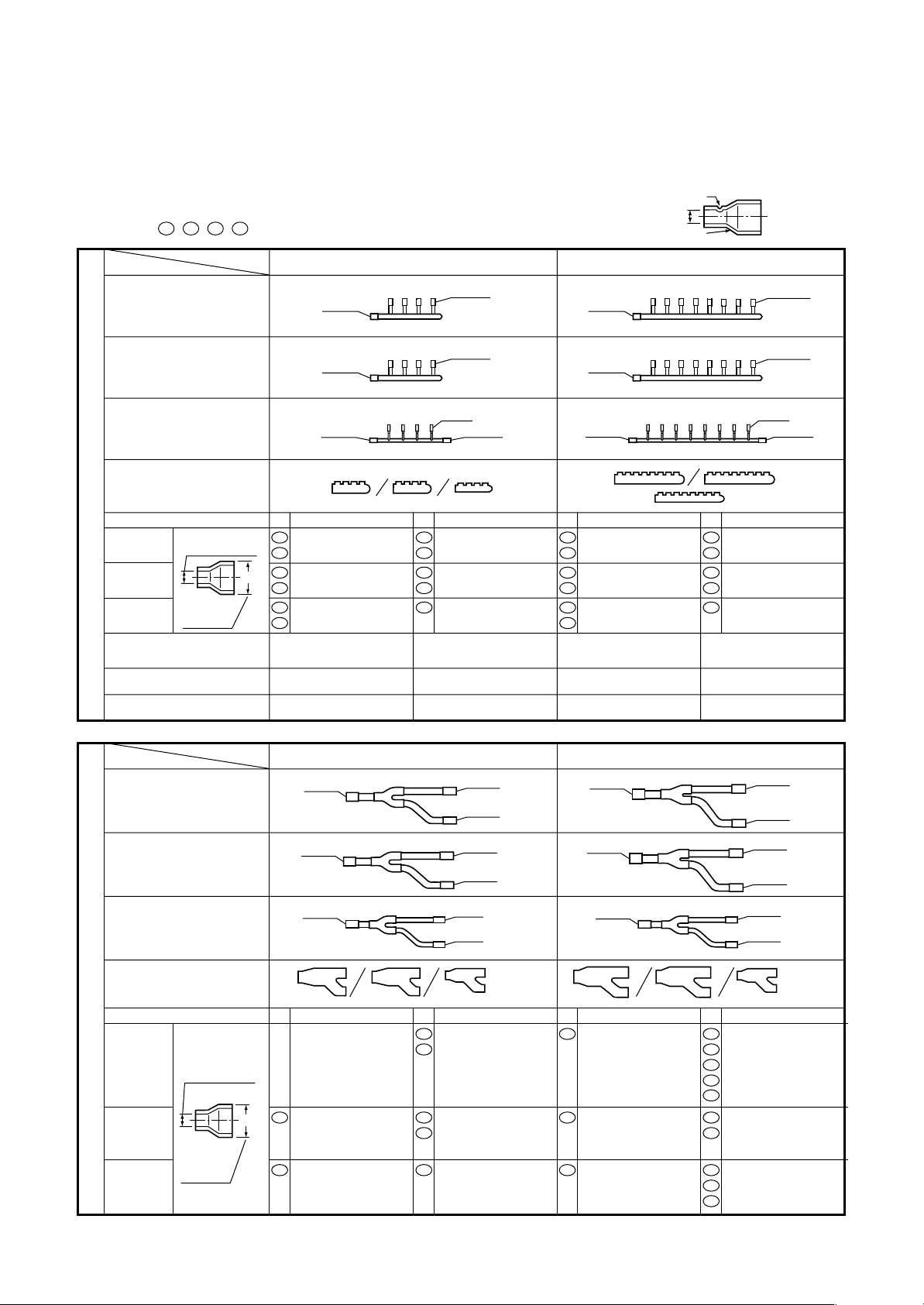
Branching Header : RBM-HY1043FE / HY1083FE
Branching Joint : RBM-BY53FE / BY103FE
• Check the following parts in the package.
• For piping material and size of the refrigerant pipes, refer to the Installation Manual of the Air Conditioner.
NOTE : 1. All dimensions are in millimeters. In the following tables, ( ) indicates diameter of the indicated position, and
others indicate diameter of the connecting pipe.
2. Please connect pipe to the side with a projection of the socket.
( 52 , 54 , 70 , 89 : without projection)
Diameter of the
connecting pipe
projection
socket
NAME
MODEL
Suction gas side
Discharge gas side
Liquid side
Heat insulator
(suction gas side/
discharge gas side/liquid side)
Socket
Suction
gas side
Discharge
gas side
Branching Header
Liquid
side
Outlet sealed pipe at suction gas side
Outlet sealed pipe at discharge gas side
Outlet sealed pipe at liquid side
Header sealed pipe at liquid side
diameter of the
connected pipe
external
diameter
of socket
No. No. No. No.
14
70
85
( )
18
06
09
Ø22.2
Ø22.2
Ø15.9
Ø15.9 x (Ø22.2) 1pc
Ø28.6 x (Ø22.2) 1pc
Ø12.7 x (Ø22.2) 1pc
Ø19.1 x (Ø22.2) 1pc
Ø 9.5 x (Ø15.9) 1pc
Ø12.7 x (Ø15.9) 1pc
Ø15.9
Ø15.9
Ø9.5
Ø15.9
06
Ø 9.5 x (Ø15.9) 3pcs
09
Ø12.7 x (Ø15.9) 4pcs
06
Ø 9.5 x (Ø15.9) 4pcs
09
Ø12.7 x (Ø15.9) 4pcs
01
Ø 6.4 x (Ø 9.5) 4pcs
(Ø15.9) 1pc
(Ø15.9) 3pcs
(Ø 9.5) 1pc
(Ø15.9) 1pc
RBM-HY1083FERBM-HY1043FE
Ø22.2
1pc 1pc
Ø22.2
1pc 1pc
Ø15.9
1pc 1pc
1pc each 1pc each
14
Ø15.9 x (Ø22.2) 1pc
70
Ø28.6 x (Ø22.2) 1pc
85
Ø12.7 x (Ø22.2) 1pc
18
Ø19.1 x (Ø22.2) 1pc
06
Ø 9.5 x (Ø15.9) 1pc
09
Ø12.7 x (Ø15.9) 1pc
06
09
06
09
01
Ø15.9
Ø15.9
Ø9.5
Ø15.9
Ø 9.5 x (Ø15.9) 7pcs
Ø12.7 x (Ø15.9) 8pcs
Ø 9.5 x (Ø15.9) 8pcs
Ø12.7 x (Ø15.9) 8pcs
Ø 6.4 x (Ø 9.5) 8pcs
(Ø15.9) 3pcs
(Ø15.9) 7pcs
(Ø 9.5) 3pcs
(Ø15.9) 1pc
NAME
MODEL
Suction gas side
Discharge gas side
Liquid side
Heat insulator
(suction gas side/
discharge gas side/liquid side)
Socket
Suction
gas side
Branching Joint
Discharge
gas side
Liquid
side
diameter of the
connected pipe
( )
external
diameter
of socket
RBM-BY103FERBM-BY53FE
Ø
Ø
15.9
Ø
15.9
Ø
12.7
No. No. No. No.
05
54
09
Ø12.7 x (Ø15.9) 1pc
05
Ø 9.5 x (Ø12.7) 1pc
05
54
01
12.7
Ø
12.7
Ø
12.7
Ø
12.7
Ø
9.5
Ø
9.5
Ø 9.5 x (Ø12.7) 2pcs
Ø15.9 x (Ø12.7) 2pcs
Ø 9.5 x (Ø12.7) 2pcs
Ø15.9 x (Ø12.7) 1pc
Sealed pipe
x (Ø19.1) 1pc
Ø 6.4 x (Ø 9.5) 2pcs
1pc 1pc
1pc 1pc
1pc 1pc
1pc each 1pc each
Ø
22.2
Ø
22.2
Ø
15.9
70
Ø28.6 x (Ø22.2) 1pc
18
Ø19.1 x (Ø22.2) 1pc
09
Ø12.7 x (Ø15.9) 1pc
07
10
13
52
89
10
52
02
05
54
Ø
19.1
Ø
19.1
Ø
19.1
Ø
19.1
Ø
12.7
Ø
12.7
Ø 9.5 x (Ø19.1) 1pc
Ø12.7 x (Ø19.1) 1pc
Ø15.9 x (Ø19.1) 2pcs
Ø22.2 x (Ø19.1) 2pcs
Ø28.6 x (Ø19.1) 1pc
Ø12.7 x (Ø19.1) 2pcs
Ø22.2 x (Ø19.1) 1pc
Sealed pipe
x (Ø19.1) 1pc
Ø 6.4 x (Ø12.7) 1pc
Ø 9.5 x (Ø12.7) 2pcs
Ø15.9 x (Ø12.7) 1pc
19
Page 20
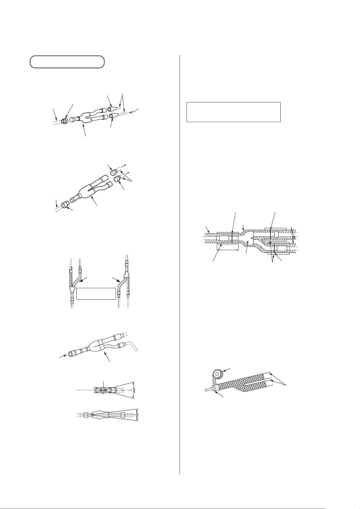
5-7. Branching Kit Connection Method
[1] Branch joint
<Suction gas/Discharge gas side>
Socket
Pipe in use
on the site
Inlet
To outdoor unit
Socket
Gas side branch joint
Outlet (2)
Outlet (1)
<Liquid side>
Socket
Outlet (1)
Pipe in use
on the site
Inlet
To outdoor unit
Socket
• Installation direction of branch pipe
Install the branching pipes so that it branch either
vertically or horizontally.
Outlet (2)
Gas/Liquid side branch joint
Both directions
are possible.
Pipe in use on the site
To other branching
pipe or indoor unit
Socket
To other branching pipe or indoor
unit
Pipe in use
on the site
Socket
NOTE :
Install the branch pipes horizontally or vertically so
that they branch evenly.
Install the branching joint within ± 15 degrees.
Heat insulating for pipes
(Branching Joint)
• In order to prevent dripping at the place where the
insulation provided with the branching kit meets the
insulating material obtained on the site, butt the two
types of insulation up against each other, and then
wrap the seam between the two types of insulation
in at least 10mm of the insulating material (in use
on the site).
<Suction gas/Discharge gas/Liquid side>
Heat insulator
for piping
(in use on the site)
Heat insulator (in use on the site)
by 10mm or more thickness.
Butt together
150
Branching joint
Heat insulator
in package
Butt together
Heat insulator for piping
(in use on the site)
Butt together
In case of vertical
installation
<Suction gas/Discharge gas/Liquid side>
A
B
(Horizontal line)
(A view)
(Horizontal line)
(B view)
<In case of horizontal installation>
NOTE :
• Install the branch pipes horizontally or vertically so
that they are branched evenly.
• Install the branching joint within ±15 degrees.
Within
± 15
Within
± 15
degrees
degrees
• On the gas-side pipe, use insulation that can
withstand heat of 120°C or higher. For the branch
pipe, either use a commercially available coupling
cover (for T-shape) that is at least 10mm thick, or
else insulate the pipe as shown in the figure at
below.
• After applying insulation as outlined above, tape the
insulation in place.
Taping (in use on the site)
Heat insulator
Heat insulator
(in use on the site)
(in use on the site)
20
Page 21
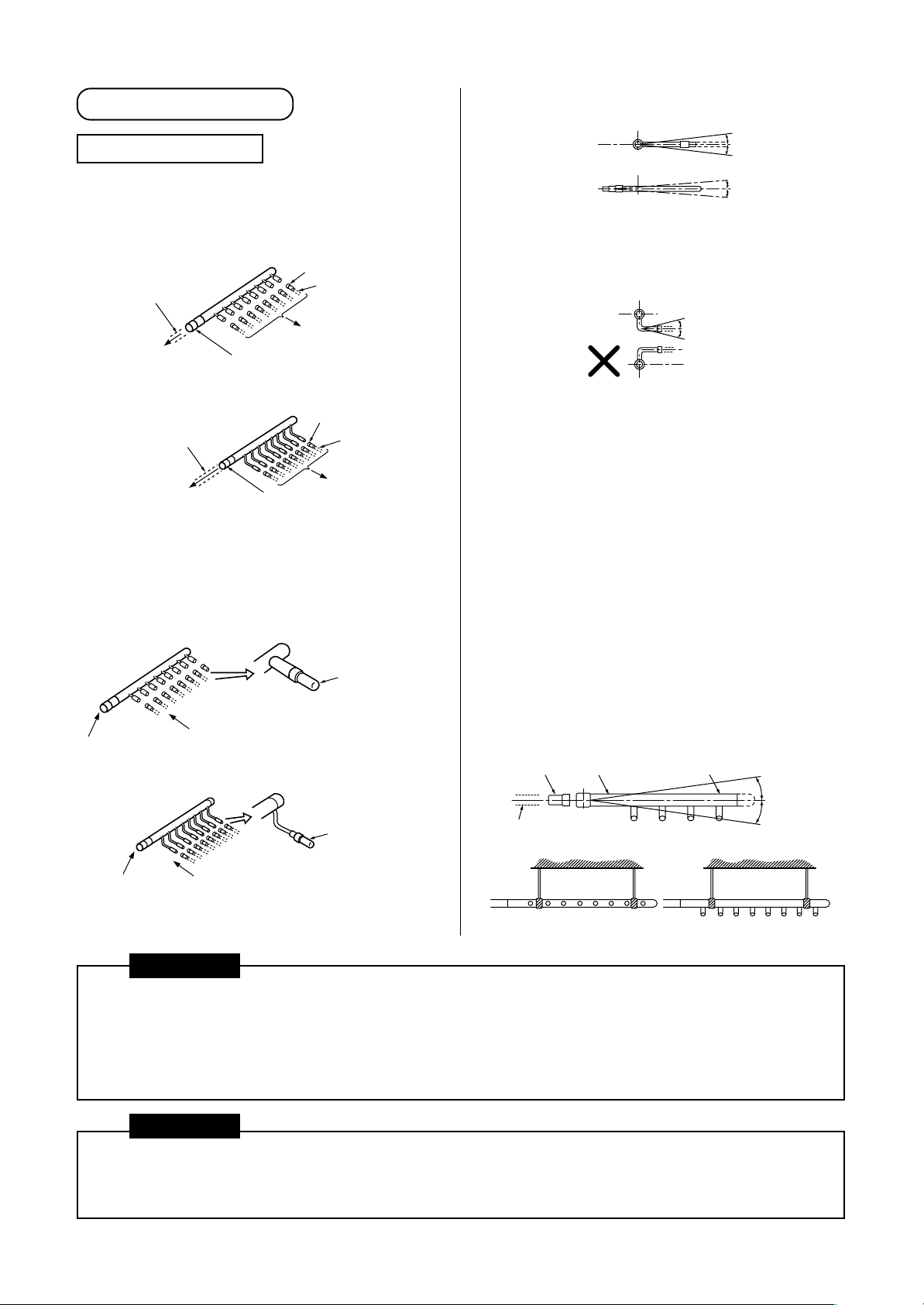
[2] Branch header
<Suction gas/Discharge gas side>
Branching Header
Select and install the socket that matches the
diameter of a pipe to be connected to the indoor unit.
<Suction gas/Discharge gas side branch
header>
Pipe in use on the site
To outdoor unit
Socket
Socket
Pipe in use on the site
To indoor unit
<Liquid-side branch header>
Socket
Pipe in use on the site
To outdoor unit
Socket
Pipe in use
on the site
To indoor unit
• If the number of indoor units to be connected is
fewer than the maximum number of units that can
be connected to the branch header, attach a sealed
pipe to the unused connectors.
<Suction gas/Discharge gas side branch
header>
Outlet sealed pipe
(Provided with
branch header)
A
B
<Liquid-side branch header>
Outlet sealed pipe
(Provided with
branch header)
C
• Install the branch header so that it branches
horizontally. It cannot be used in a vertical position.
D
(Horizontal line)
(Horizontal line)
(A view)
(B view)
Within
± 15
Within
± 10
degrees
degrees
<Liquid-side>
(Horizontal line)
(C view)
When arranging the branching header at the liquid
side, attach a header sealed pipe on the sealing side
of the header as shown in the fiqure at below.
Be sure to install the branch pipe downward.
Horizontal viewed from D point should be within ± 10
degrees same as view B.
• Supporting branching header
After applying the insulation, set the hanging metals
as support. (in use on the site).
NOTE :
1. Install the branching header so that it branches
horizontally. It cannot be used in a vertical
position.
2. Do not use T-type pipe for the branching section.
Inlet socket
Pipe in use
on the site
Branching Header
(D view) Sealing side
Within
degrees
± 15
Header sealed pipe
Within
± 10
degrees
CAUTION
1. On the inlet side of a Y-type branch joint or branch header, allow for at least 300mm of straight pipe.
2. A Y-type branch joint can be installed so that it branches either vertically or horizontally; if branching
horizontally, it should be within an angle of ± 15°.
3. A branch header should be installed so that it branches horizontally.
4. Do not use T-type branch joints.
CAUTION
In the multi air conditioning system, because the refrigerant pipes congregate at the rooftop pipeshaft outlet
in the vertical pipeshaft, it is necessary to attach “labels” to each pipe in order to make clear to which system
a given pipe belongs so as to prevent pipes from being connected incorrectly.
21
Page 22
How to connect “Cooling Only” indoor unit
Branch joint
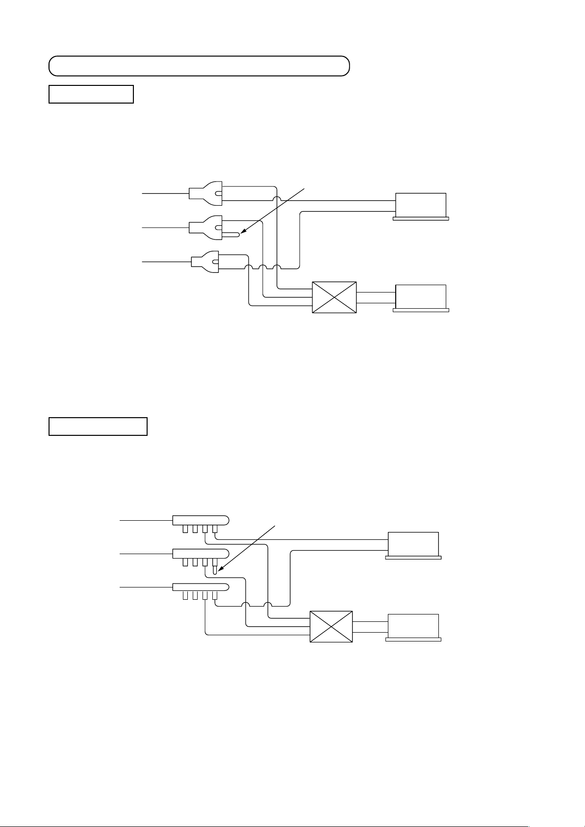
• When connecting a Cooling Only indoor unit, attach a sealed pipe to the unused connectors of the branching
pipe of discharge gas side.
Suction gas side
* Discharge gas side
Liquid side
∗ Refer to above. There is the method of connecting without using branching joint pipe of discharge gas side.
For details, refer to the Installation Manual of the Air Conditioner.
Connect sealed pipe.
Flow selector unit
Indoor unit
Cooling only
Indoor unit
Heating and Cooling
Branch header
• When connecting a Cooling Only indoor unit, attach a sealed pipe to the unused connectors of the branching
pipe of discharge gas side.
Suction gas side
Connect sealed pipe.
Discharge gas side
Liquid side
Flow selector unit
Indoor unit
Cooling only
Indoor unit
Heating and Cooling
[NOTE]
For cooling only indoor unit in Super-HRM system, item code (DN) setting from the wired remote controller is
necessary. (Refer to the section “13-1.”)
22
Page 23
5-8. External Dimensions of Branch Connectors
y
y
y
y
y
(Outline drawings are shown on the following pages.)
Branching joints and headers
Model name Usage Appearance
RBM-BY53FE
RBM-BY103FE
Y-shape branching joint (*2)
RBM-BY53E
RBM-BY103E
RBM-HY1043FE
4-branching header (*3)
RBM-HY1043E
RBM-HY1083FE
8-branching header (*3)
RBM-HY1083E
1 If total capacity code value of indoor unit exceeds that of outdoor unit, apply capacity code of outdoor unit.
*
2 When using Y-shape branching joint for 1st branching, select according to capacity code of outdoor unit.
*
3 Max. 6.0 capacity code in total can be connected.
*
4 This is used for branching to “cooling only” indoor unit.
*
5 Model names for outdoor and indoor units described in this guide are shortened because of the space constraint.
*
Indoor unit capacit
Total below 6.4
Indoor unit capacit
Total below 14.2
Indoor unit capacit
Total below 6.4
Indoor unit capacity code
Total below 14.2
Indoor unit capacit
Total below 14.2
Indoor unit capacity code
Total below 14.2
Indoor unit capacit
Total below 14.2
Indoor unit capacity code
Total below 14.2
code
code
code
code
code
For 3 piping
For 2 piping (*4)
For 3 piping
For 2 piping (
For 3 piping
For 2 piping (
4)
*
4)
*
5-9. Nitrogen Gas Blow Method (During Brazing)
• If nitrogen gas is not passed through the pipes during brazing, a film of oxidized material will form on the inner
surfaces of the pipes. The presence of a such a film in the system will adversely affect the operation of the
valves and compressor in the refrigerant system, and will prevent the system from operating normally.
• In order to prevent this from occurring, nitrogen gas is passed through the pipes while brazing is in progress.
This process of replacing the air in the pipes with nitrogen is called the “nitrogen gas blow.”
This is the basic method that is used for brazing work.
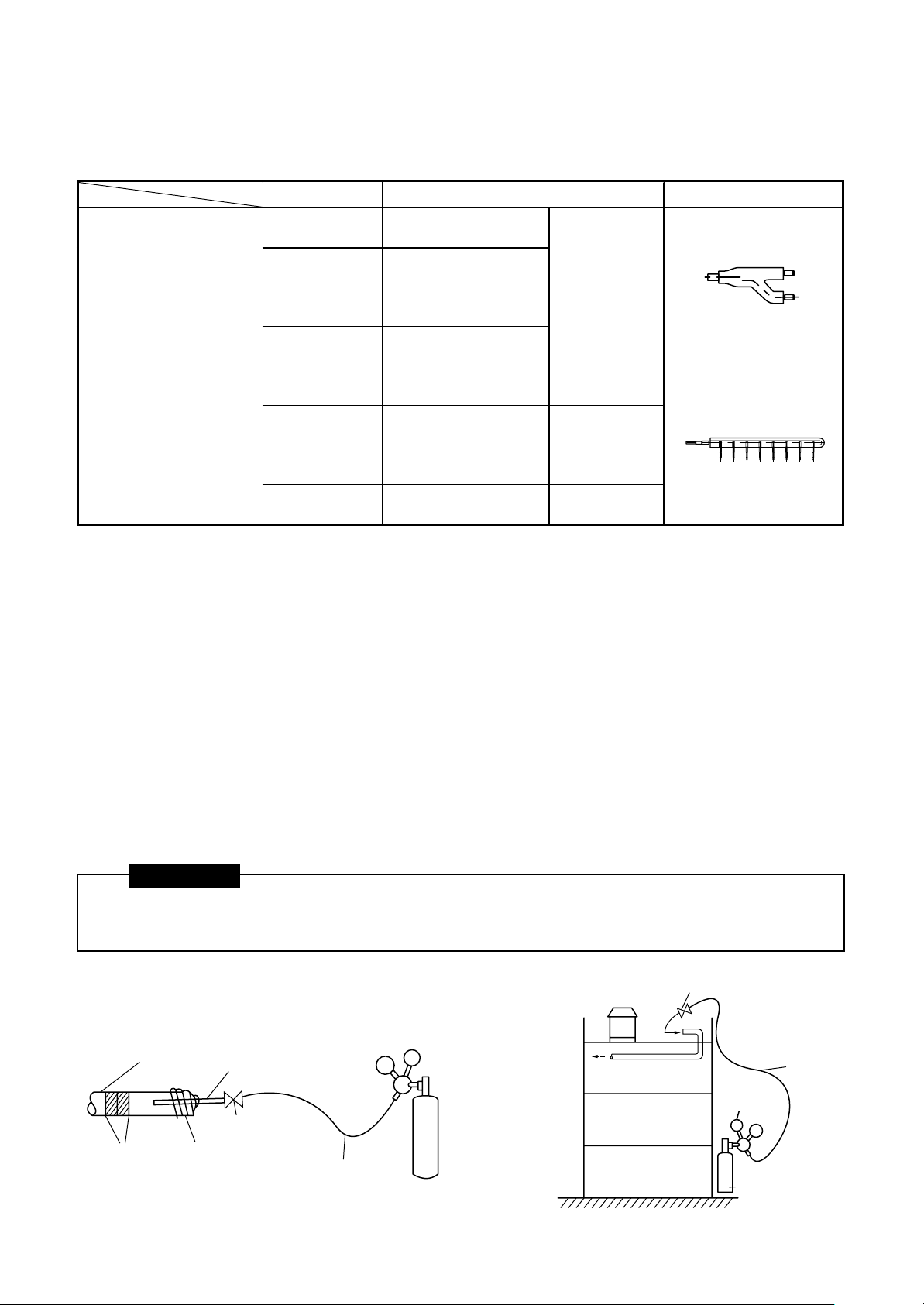
CAUTION
1. Nitrogen gas must be used. (Oxygen, carbon dioxide, and fluorocarbons cannot be used.)
2. Always be sure to use a pressure-reducing valve.
Piping
Valve
Hose
Reducing
valve
Nitrogen
gas bomb
Piping at site
Brazing
position
Copper pipe Ø6.4
Valve
Taping
Reducing valve
Pressure
tight hose
Outside
Nitrogen
gas bomb
23
Page 24
5-10. Brazing Work
1. Brazing work should be performed downwards or
(Recommended brazing)
sideways. Avoid brazing upwards (in order to
avoid incomplete brazing). (Recommendation)
2. Always used the specified piping materials for
liquid pipes and gas pipes, and make sure that
Brazing material
they are installed in the proper direction and at
the proper angle.
3. The “nitrogen gas blow” method should be used
when brazing.
(Direction downward) (Direction upward)
Lateral direction
Brazing
material
Brazing
material
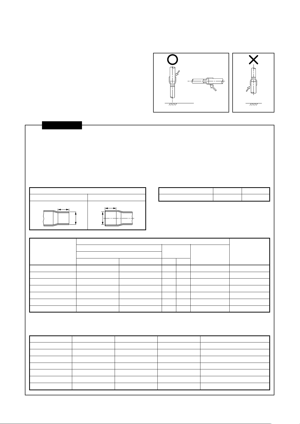
CAUTIONS
1. Pay attention to fire prevention concerns. (Take preventative measures in the area where brazing work is
to be performed, such as keeping a fire extinguisher or water handy.)
2. Be careful not to burn yourself.
3. Make sure that any gaps between pipes and couplings are appropriate. (Do not miss brazing any joints.)
4. Make sure that pipes are adequately supported.
• The following table provides basic guidelines for the interval between supports for horizontal copper pipe.
Coupling size of brazed pipe
Connected section
External size Internal size
K
ØC
G
ØF
Interval between supports for copper pipe
Nominal dia.
Max. interval (m)
• Avoid securing copper pipes with metal brackets
directly.
20 or less 25 to 40
1.0 1.5
(Unit: mm)
Connected section
Standard outer dia. of
connected copper pipe
6.35
9.52
12.70
15.88
19.05
22.22
28.58
External size Internal size
Standard outer dia. (Allowable difference)
CF
6.35 (±0.03) 6.45 ( )
9.52 (±0.03) 9.62 ( )
12.70 (±0.03) 12.81 ( )
15.88 (±0.03) 16.00 ( )
19.05 (±0.03) 19.19 ( )
22.22 (±0.03) 22.36 ( )
28.58 (±0.04) 28.75 ( )
+0.04
–0.02
+0.04
–0.02
+0.04
–0.02
+0.04
–0.02
+0.03
–0.03
+0.03
–0.03
+0.06
–0.02
Min. depth
of insertion
KG
76
87
98
98
11 10
11 10
13 12
Oval value
0.06 or less
0.08 or less
0.10 or less
0.13 or less
0.15 or less
0.16 or less
0.20 or less
Min. thickness
of coupling
0.50
0.60
0.70
0.80
0.80
0.82
1.00
∗ Gas brazing of refrigerant pipes must be performed by personnel qualified to do so under local ordinances.
Minmum wall thickness for R410A application
Soft (Coil)
¡
¡
¡
¡
NG
NG
NG
Hard or Half hard
¡
¡
¡
¡
¡
¡
¡
OD (Inch)
1/4
3/8
1/2
5/8
3/4
7/8
1.1/8
OD (mm)
6.35
9.52
12.70
15.88
19.05
22.20
28.58
Minium wall thickness
0.80
0.80
0.80
1.00
1.00
1.00
1.00
24
Page 25
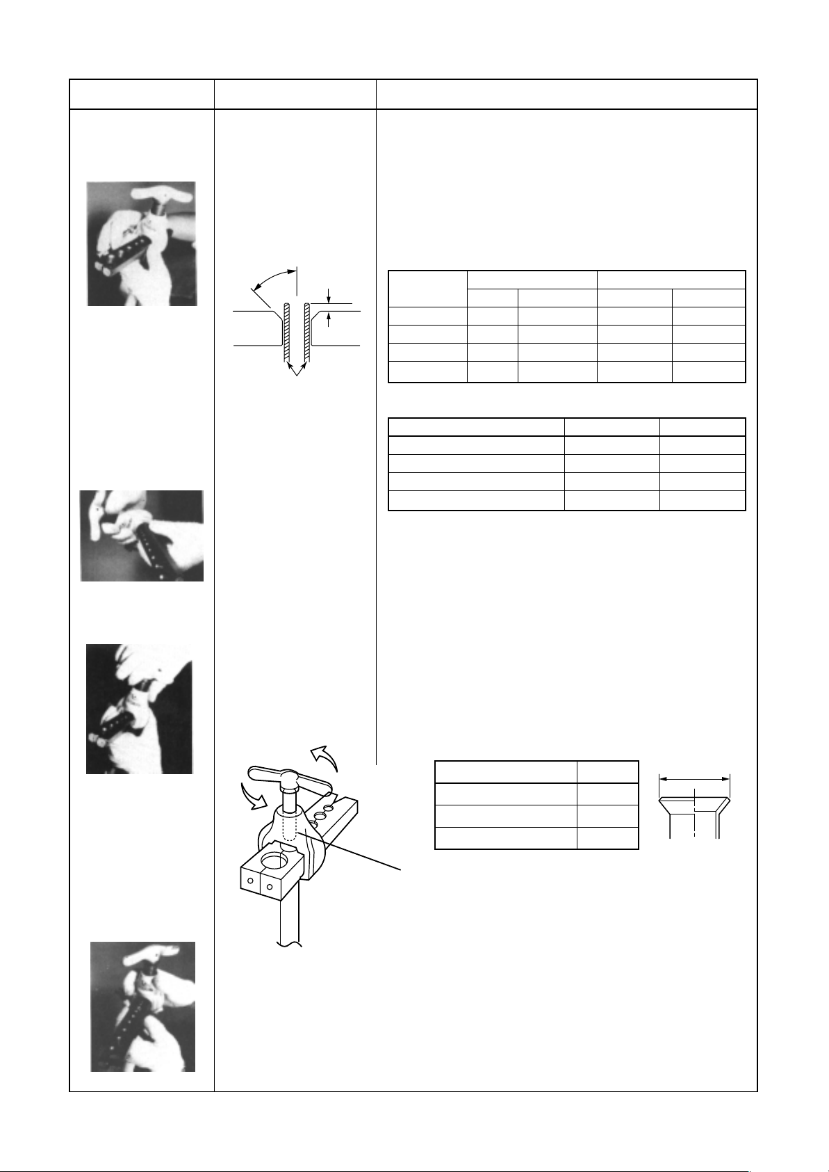
5-11. Flare Processing
Flare processing procedure
Parts and material : Copper pipe, flare nut. Flare nut shallbe of attached on the indoor unit or R410A exclusive.
Tools : Flare tool (“Rigid” type), reamer, pipe cutter
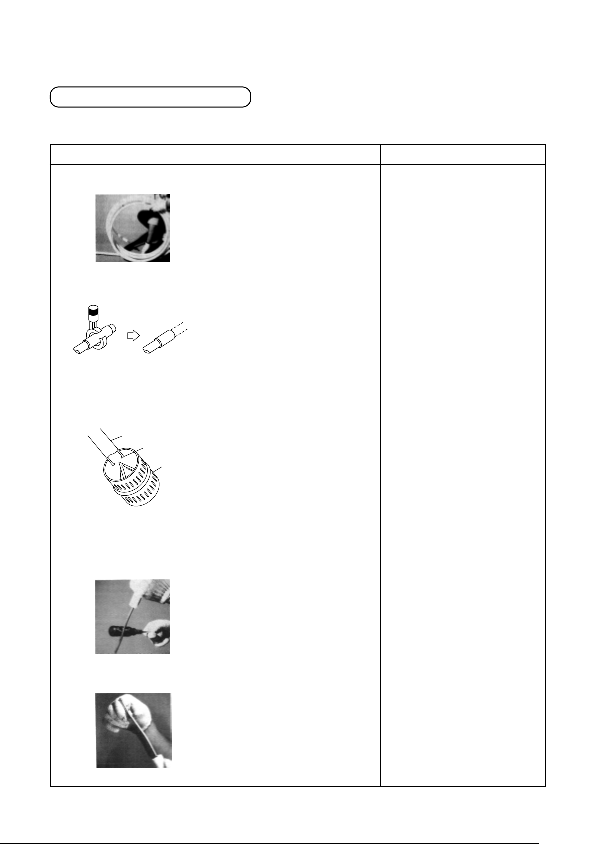
Work procedure
Straighten the coiled copper pipe.
Cut the pipe with the pipe cutter.
Use the reamer to remove burrs
from the cut surface of the pipe.
Pipe
Burr
Deburring
Key point
Uncoil the pipe.
1. Position the blade of the cutter
so that it will cut the pipe at a
perpendicular angle.
2. Rotate the pipe cutter to the
left to cut the pipe.
3. Move the pipe cutter slowly.
1 . Keep the opening of the pipe
facing downwards.
2. Be careful not to scratch the
inner surface of the pipe.
(Reason)
• It is difficult to cut the coiled pipe
correctly, which increases the
chance of failure.
• The cut surface will be at an
angle.
• The cutter will bite too tightly.
• The copper pipe will be
deformed.
• Scraps will get inside of the
pipe.
• A gas leak could result.
Clear out the inside of the pipe by
tapping on the end with a
screwdriver.
Insert the flare nut.
Make sure that all scraps of metal
are out of the tube by lightly
tapping on the tube while the
opening is pointing down.
Be certain to insert the flare nut
before beginning the flare
process.
25
• Metal scraps in the tube can
damage the compressor.
• If the scraps adhere to the
flared region, a gas leak may
result.
• The flare nut will not fit inside
the copper pipe after the flare
process.
Page 26
Work procedure
Key point
(Reason)
Attach the (“Rigid”)
flare tool to the
copper pipe.
Align the punch.
(Align the arrow with
the line adjacent to
the next hole.)
1. Make sure that the
inner surfaces of the
flare tool are clean.
2. Determine the
dimensions of the
copper pipe in
accordance with the
flare tool.
45˚
A
Flare tool
Copper pipe
Align the arrow on the
punch with the
prescribed position on
the flare tool.
• The copper pipe will slip out while the flaring process is in
progress.
• The flared dimensions vary.
Dimensions to end of copper tube when flared with one tool
surface
• Projection margin in flaring : A (Unit : mm)
Rigid (Clutch type)
Outer dia. of
copper pipe
6.4
9.5
12.7
15.9
R410A tool used
R410A R22
0 t o 0 .5 (Same as left)
0 t o 0 .5 (Same as left)
0 t o 0 .5 (Same as left)
0 t o 0 .5 (Same as left)
Conventional tool used
R410A R22
1.0 to 1.5 0.5 to 1.0
1.0 to 1.5 0.5 to 1.0
1.0 to 1.5 0.5 to 1.0
1.0 to 1.5 0.5 to 1.0
Imperial (Wing nut type)
Outer dia. of copper pipe
6.4
9.5
12.7
15.9
R410A R22
1.5 to 2.0 1.0 to 1.5
1.5 to 2.0 1.0 to 1.5
2.0 to 2.5 1.5 to 2.0
2.0 to 2.5 1.5 to 2.0
Flare the pipe.
Remove the flare tool
and check the flared
surface.
Slowly and carefully turn
the flare tool handle
while it clicks, until it
turns freely. Turn the
handle to the left and
raise it to the top.
If the handle is not raised to the
top, the flare tool will scratch the
extended portion of the pipe
(the cone-shaped portion).
• If the “A” dimension is small, the flared contact surface is
smaller and a gas leak becomes more likely.
• The pipe will not be flared fully.
• The extended portion of the pipe (the cone-shaped portion)
will be scratched.
• Extruding margin of copper pipe
with flare machining : A (Unit: mm)
Copper pipe outer dia.
9.5
12.7
15.9
A
13.2
16.6
19.7
+0.0
–0.4
A
Check list :
• Is the inner surface of the flared portion equal in width and shiny?
• Is the thickness of the flared portion equal?
• Is the flared portion of a suitable size?
26
Page 27
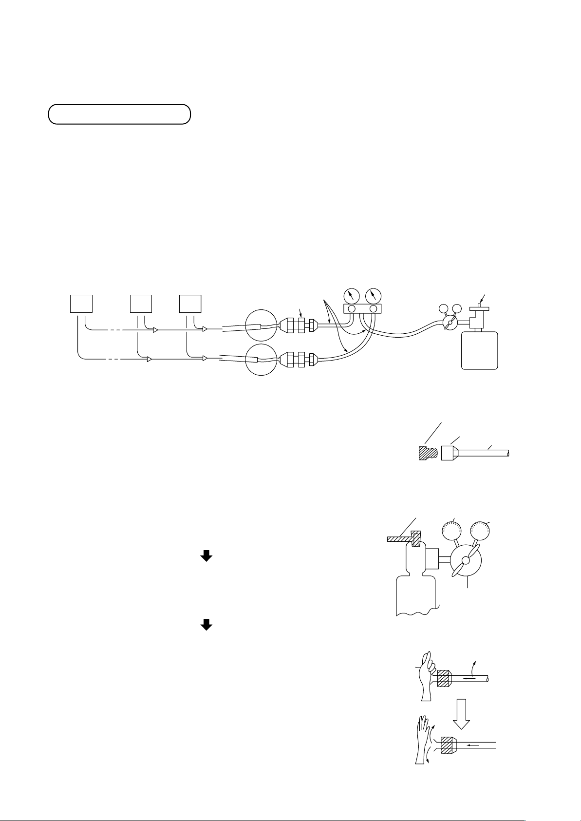
5-12. Flushing
The flushing process uses gas pressure to remove foreign matter from the inside of pipes.
Three major effects
(1) Removes oxidation that formed inside of the pipe during brazing as a result of an inadequate “nitrogen gas
blow” procedure.
(2) Removes foreign matter and moisture that has gotten inside of pipes due to improper handling.
(3) Checks the connections in the pipe system between the indoor unit and the outdoor unit.
[Example work procedure]
1. Install a pressure reducing valve on a nitrogen cylinder. (Fluorocarbon gases and carbon dioxide carry a risk
of promoting condensation, while oxygen causes explosion.)
2. Connect the pressure reducing valve to a gauge manifold and then to the gas-side pipe and the liquid-side
pipe on the outdoor unit.
Indoor unit
Ø6.4 copper pipe
N21
Diff. size union
3. On the indoor unit side, plug all gas-side pipes except those for the
indoor units that are to be flushed.
4. Open the source valve on the nitrogen cylinder and increase the
pressure on the secondary side of the pressure reducing valve until it
reaches 0.5MPa (5kg/cm2G), and then open the valve on the gauge
manifold connected to the gas-side pipe.
5. Flushing
Press down on the end of the indoor-side gas pipe with your palm.
VLV
H
Gauge
manifold
valve
Source
valve
Reducing
valve
Nitrogen gas bomb
Plug (Brass)
1st side
Source valve
Flare nut
Copper pipe
2nd side
0.5MPa
(5kg/cm²G)
When the pressure becomes so great that you can no longer hold it
against the end of the pipe, remove your hand from the pipe. (This is
the first flush.) Press down against the end with your hand again.
Flush the pipe a second time.
(When flushing, place a piece of gauze, etc., on the end of the pipe,
and then check the gauze for debris or moisture. Repeat the flushing
process until nothing more comes out of the pipe.)
6. Close the gauge manifold valve, and repeat the above process for
next indoor unit (No. 2 to No. N). Close the gauge manifold valve,
open the valve on the gauge manifold that is connected to the liquidside pipe to allow the nitrogen to flow, and flush that liquid-side pipe.
27
Nitrogen
Hand
gas
Reducing valve
Pressure
0.5MPa (5kg/cm²G)
Page 28
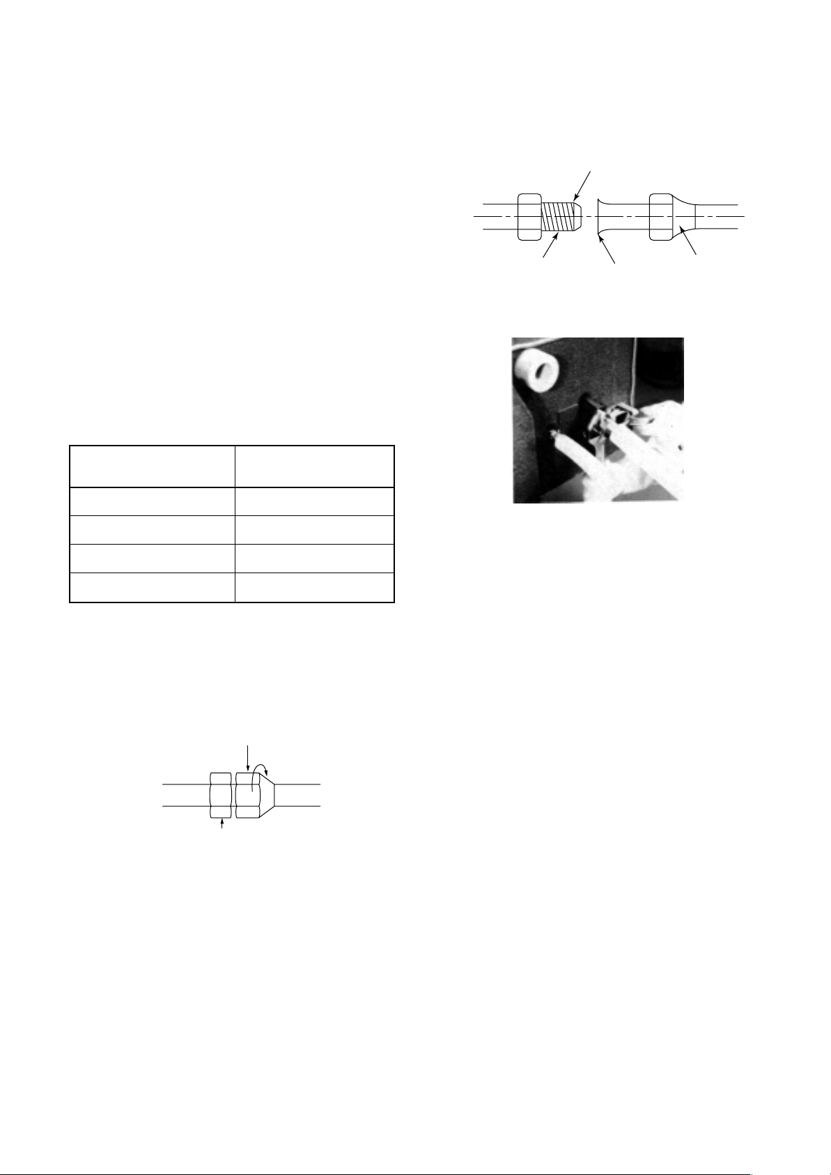
5-13. Pipe Connections to the Indoor Unit
1. Once you remove the flare nut from the pipe on
the indoor unit (always use a torque wrench), a
small amount of gas will escape, but this is simply
nitrogen gas with atmospheric pressure that was
sealed inside to prevent corrosion, and does not
indicate a problem.
2. Flare the pipe according to the procedure
described previously.
3. Centering
Center the pipes be seating the tapered portion of
the half union in the flared portion of the pipe.
4. Tightening the flare nut
First hand-tighten the flare nut as much as
possible, and then use a torque wrench to tighten
the nut completely.
<Indoor unit> <Pipe>
Center
Brazing union
(half union)
Tapered portion
Flared portion
Flare nut
Connecting pipe outer dia.
(mm)
Ø6.4
Ø9.5
Ø12.7∗
Ø15.9∗
Tightening torque
(N•m)
14 to 18 (1.4 to 1.8 kgf•m)
34 to 42 (3.4 to 4.2 kgf•m)
50 to 62 (5.0 to 6.2 kgf•m)
68 to 82 (6.8 to 8.2 kgf•m)
∗ : R410A torque wrench required.
<Two spanners>
Turn flare nut with a wrench
<Indoor unit> <Pipe>
Secure half union in place with a wrench
Tightening the flare nut with a torque wrench
* Avoid initially tightening the nut with a wrench.
* When tightening a 6.4mm-diameter pipe, tighten the nut lightly with a wrench, and then tighten the nut about
90° to 120° (1.5 to 2 corners of the nut) with a torque wrench.
28
Page 29
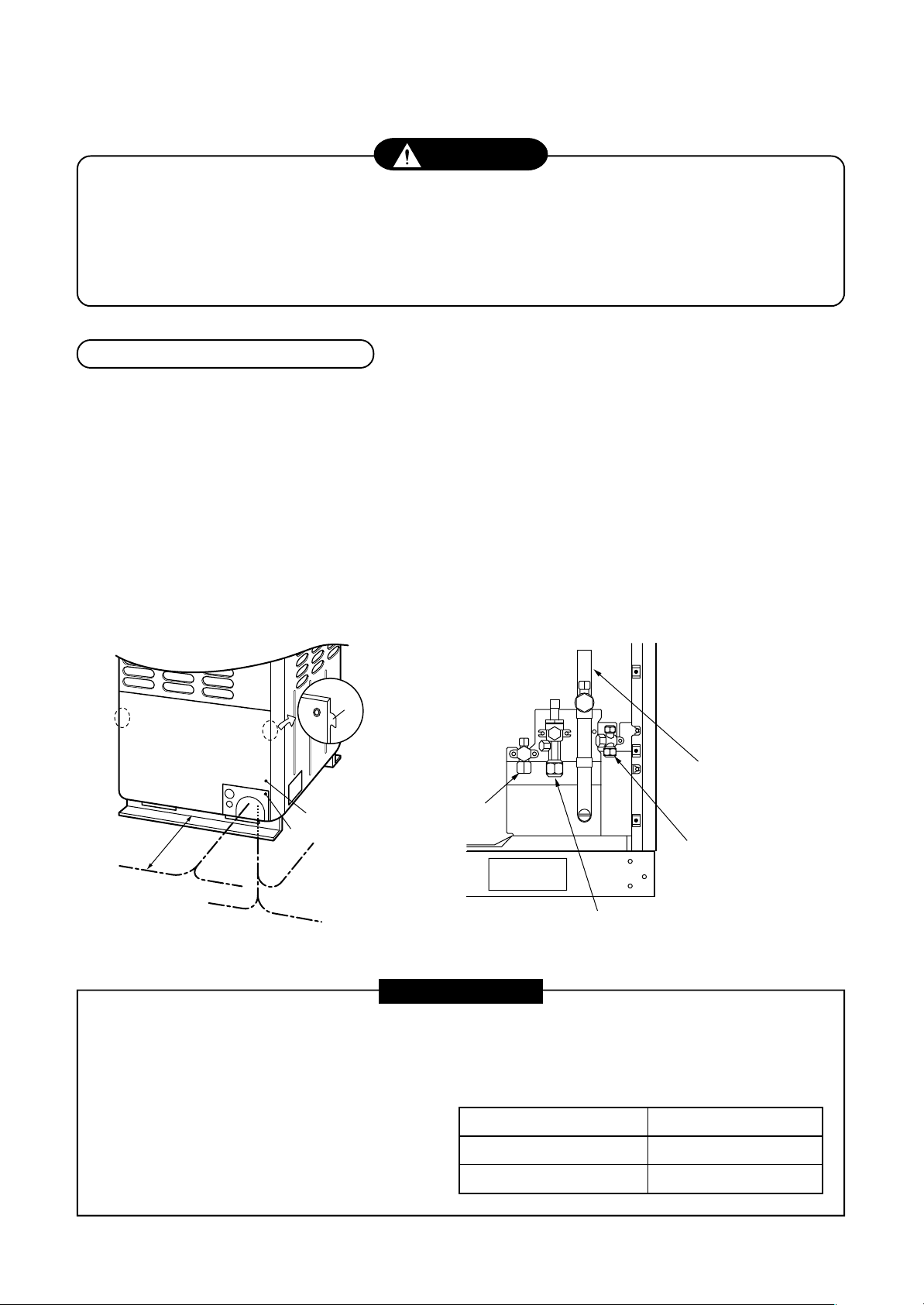
5-14. Pipe Connection to the Outdoor Unit
WARNING
If the refrigerant gas leaks during installation work, ventilate the room.
If the leaked refrigerant gas comes to contact with a fire, the noxious gas may generate.
After installation work, check that the refrigerant gas does not leak.
If the refrigerant gas leaks in the room and comes to contact with a fire such as fan heater, stove, or kitchen
range, the noxious gas may generate.
Connection of refrigerant pipe
1. The refrigerant pipe connecting section is set in the outdoor unit. Remove the front panel and the piping/wiring
panel. (M5: 9 pcs.)
• As shown in the right figure, the hooking hooks are attached at right and left sides each on the front panel.
Lift up and remove the front panel.
2. Pipes can be drawn out forward and downward from the outdoor unit.
3. When drawing out the pipe forward, draw out the pipe to outside via piping/wiring panel, and keep space of
500mm or more from the main pipe connecting the outdoor unit with the indoor unit, considering service work,
etc. (For replacing the compressor, 500mm or more space is required.)
4. When drawing out the pipe downward, remove the knockout of the base plate of the outdoor unit, apply the
pipe to outside of the outdoor unit, and perform piping at right/left or rear side. Leading pipe of the balancing
should be within 4m.
Hook
Packed valve at
suction gas side
(Left piping)
500mm
or more
Drawing out
forward
(Left piping)
(Right
piping)
Drawing out
downward
Front panel
Piping/wiring panel
(Rear piping)
(Right piping)
Packed valve
at liquid side
Packed valve at balance side
(It is not used in this model.)
Ball valve at discharge gas side
REQUIREMENT
For brazing, be sure to use nitrogen gas to avoid oxidation of pipe inside.
1. In a welding work for the refrigerant pipes, be sure to use the nitrogen gas in order to prevent oxidation
inside of the pipes; otherwise clogging of the refrigerating cycle due to oxidized scale generates.
2. Use clean and new pipes for the refrigerant pipes and perform piping work so that water or dust is not
mixed.
3. Be sure to use a double spanner to loosen
or tighten the flare nut. If a single spanner is
used, a required tightening cannot be obtained.
Tighten the flare not with the specified torque.
Outer dia. of copper pipe
12.7 mm
15.9 mm
Tightening torque (N•m)
50 to 62 (5.0 to 6.2 kgf-m)
68 to 82 (6.8 to 8.2 kgf-m)
29
Page 30
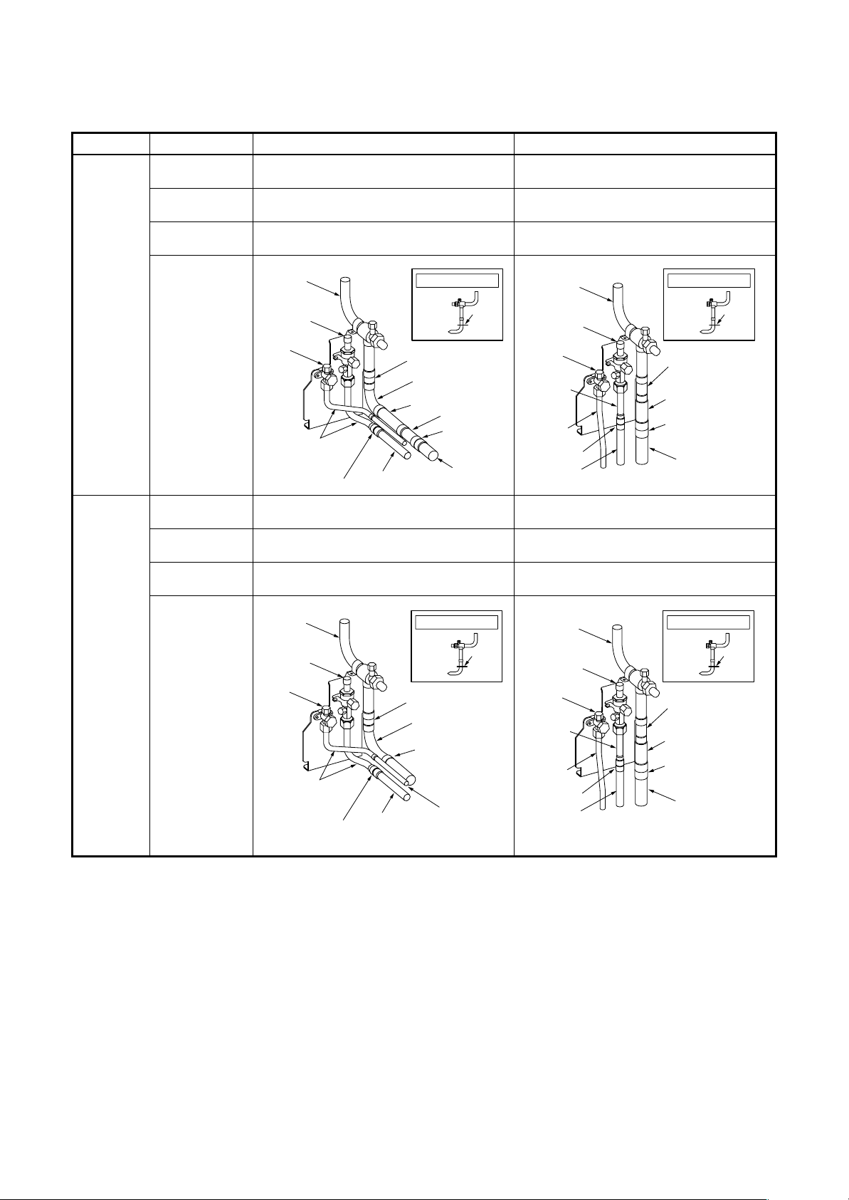
Pipe connecting method of valve (Example)
Using the attached pipes as shown in the following figure, braze elbows, sockets, and pipes which are procured locally.
MMY- Drawing out forward Drawing out downward
Liquid pipe Use the attached pipe for connection.
Discharge gas pipe
Suction gas pipe
Use the attached pipe (L-shape) and connect it
with socket.
Cut L-shape pipe and connect it with elbow,
attached pipe and socket.
Pipe connection at the local site
(Bend rightward slightly.)
Use the attached pipe (Straight pipe) and connect
it with socket.
Cut L-shape pipe and connect it with attached pipe
and socket.
MAP0801FT8
MAP1001FT8
MAP1201FT8
Suction gas pipe
Discharge
gas pipe
Liquid pipe
Attached pipe
Socket
Pipe
Suction gas pipe
L-shape pipe
Attached pipe
Pipe
Attached pipe
Socket
Pipe
Cut
Liquid pipe Use the attached pipe for connection.
Discharge gas pipe Use the attached pipe and connect it with socket.
Suction gas pipe
Cut L-shape pipe and connect it with attached
pipe.
Suction gas pipe
Discharge
gas pipe
Liquid pipe
Attached pipe
Socket
Pipe
Suction gas pipe
Cut
L-shape pipe
Attached pipe
Pipe
Pipe
Suction gas pipe
Discharge
gas pipe
Liquid pipe
Attached
pipe
Pipe
Socket
Pipe
Suction gas pipe
Cut
L-shape pipe
Attached pipe
Socket
Pipe
Pipe connection at the local site
(Bend rightward slightly.)
Use the attached pipe (Straight pipe) and connect
it with socket.
Cut L-shape pipe and connect it with attached pipe
and socket.
Suction gas pipe
Discharge
gas pipe
Liquid pipe
Attached
pipe
Pipe
Socket
Pipe
Suction gas pipe
Cut
L-shape pipe
Attached pipe
Socket
Pipe
30
Page 31

5-15. Leak Test
A leak test must be performed when connecting pipes to the refrigerant pipes in use at a site.
[1] Leak test pressure
For Super HRM air conditioner systems: 3.73MPa (38kg/cm2G)
[2] Test method
After the refrigerant piping has finished, execute an airtight test. For an airtight test, connect a nitrogen gas bomb as
shown in the figure below, and apply pressure.
• Be sure to apply pressure from the service ports of the packed valves (or ball valves) at liquid side, discharge gas
side, and suction gas side.
• An airtight test can be only performed to the service ports at liquid side, discharge gas side, and suction gas side of the
outdoor unit.
• Close fully valves at liquid side, discharge gas side, and suction gas side. As there is possibility that nitrogen gas
enters in the refrigerant cycle, re-tighten the valve rods before applying pressure. (Re-tightening of the valve rods
are unnecessary for valves at discharge gas side because they are ball valves.)
• For each refrigerant line, apply pressure gradually with steps at liquid side, discharge gas side, and suction gas side.
Be sure to apply pressure to suction gas side, discharge gas side, and liquid side.
REQUIREMENT
Never use “Oxygen”, “Flammable gas” and “Noxious gas” in an airtight test.
Connected to indoor unit
Packed valve fully closed
(Suction gas side)
Brazed
Fully
closed
Fully
closed
Detailed drawing of packed valve
To gauge manifold
Discharge gas side
service port
Discharge gas side
ball valve
Liquid side
service port
Liquid side
packed valve
Piping at site
To
outdoor
unit
Piping
at site
To outdoor unit
Main pipe
Suction gas side
service port
Suction gas side
packed valve
To outdoor
unit
Piping
at site
STEP 1 : Apply pressure 0.3MPa (3.0kg/cm2G) for 3 minutes or more.
STEP 2 : Apply pressure 1.5MPa (15kg/cm
STEP 3 : Apply pressure 3.73MPa (38kg/cm
2
G) for 3 minutes or more.
2
G) for approx. 24 hours. Available to detect slow leakage
Lowpressure
gauge
Outdoor unit
Service
port
Service port
Ball valve fully closed
(Discharge gas side)
Packed valve fully closed
(Liquid side)
Available to detect a gross leakage
Ø6.4
Copper pipe
VLV
Ø6.4
Copper
pipe
Highpressure
gauge
Gauge
H
manifold
Reducing
valve
Nitrogen
gas
• Check pressure down.
No pressure down: Accepted Pressure down: Check the leaked position.
However, if there is difference of ambient temp. between when pressure has been applied and when
24 hours passed, pressure changes by approx. 0.01MPa (0.1kg/cm²G) per 1°C. Correct the pressure.
Leaked position check
When a pressure-down is detected in STEP 1, STEP 2, or STEP 3, check the leakage at the connecting points.
Check leakage with hearing sense, feeler, foaming agent, etc, and perform re-brazing or re-tightening of flare if
leakage is detected.
31
Page 32

NOTES
If piping is long, an airtight test is performed for each divided block.
1) Indoor side + vertical pipe
2) Indoor side + vertical pipe + outdoor side
[3] Air purge
For the air purge at installation time (Discharge of air in connecting pipes), use “Vacuum pump method” from
viewpoint of protection of earth environment.
• For protection of earth environment, do not discharge the flon gas in the air.
• Using a vacuum pump, eliminate the remained air (nitrogen gas, etc.) in the unit. If gas remains, an absence of
faculties may be caused.
After the airtight test, discharge nitrogen gas. Then connect the gauge manifold to the service ports at liquid, suction
gas, and discharge gas sides, and connect the vacuum pump as shown in the following figure. Be sure to perform
vacuuming for liquid, suction gas and discharge gas sides.
• Be sure to perform vacuuming from both liquid and gas sides.
• Be sure to use a vacuum pump with counter-flow preventive function so that oil in the pump does not back up in the
pipe of the air conditioner while the pump stops. (If oil in the vacuum pump enters in the air conditioner with R410A
refrigerant, a trouble is caused in the refrigerating cycle.)
Connected to indoor unit
Main pipe
Packed valve fully closed
(Suction gas side)
Outdoor unit
Lowpressure
gauge
VL VH
Highpressure
gauge
Gauge
manifold
Detailed drawing of packed valve
To gauge manifold
Discharge gas side
service port
Discharge gas side
ball valve
Liquid side
service port
Liquid side
packed valve
Piping at site
Suction gas side service port
Suction gas side
packed valve or
ball valve
To outdoor
unit
To
outdoor
unit
Piping
at site
To outdoor unit
Piping
at site
Brazed
Fully
closed
Fully
closed
Service
port
Service port
Ball valve fully closed
(Discharge gas side)
Packed valve fully closed
(Liquid side)
P
Vacuum pump
• Use a vacuum pump having a high vacuuming degree (below -755mmHg) and a large exhaust gas amount (over
40L/minute).
• Perform vacuuming for 2 or 3 hours though time differs due to pipe length. In this time, check all packed valves at
liquid, suction gas, and discharge gas sides are fully closed.
• If vacuuming valve amount is not decreased to below -755mmHg even after vacuuming for 2 hours or more,
continue vacuuming for 1 hour or more. If -755mmHg or less cannot be obtained by 3 hours or more vacuuming,
check the leaked position.
• When vacuuming valve reached to -755mmHg or less after vacuuming for 2 hours or more, close valves VL and VH
of the gauge manifold fully, stop the vacuum pump, leave it as it is for 1 hour, and then check the vacuuming
degree does not change. If it changed, there may be a leaked position. Check the leaked position.
• After the above procedure of vacuuming has finished, exchange the vacuum pump with a refrigerant cylinder and
advance to the additional charging of refrigerant.
32
Page 33

5-16. Charging Requirement with Additional Refrigerant
After the system has been vacuumed, replace the vacuum pump with a refrigerant cylinder and charge the
system with additional refrigerant.
Calculating the amount of additional refrigerant required
Refrigerant in the system when shipped from the factory
R410A
8HP 10HP 12HP
Refrigerant amount charged in factory Heat recovery model
When the system is charged with refrigerant at the factory, the amount of refrigerant needed for the pipes at the
site is not included. Calculate the additional amount needed, and add that amount to the system.
(Calculation)
Additional refrigerant charge amount is calculated from size of liquid pipe at site and its real length.
[Additional refrigerant charge amount at site] =
[Real length of liquid pipe] × [Additional refrigerant charge amount per liquid pipe 1m (Table 1)] × 1.3
Example : Additional charge amount R (kg) ={(L1 x 0.025kg/m) + (L2 x 0.055kg/m) + (L3 x 0.105kg/m)} × 1.3
L1 : Real total length of liquid pipe Ø6.4 (m)
L2 : Real total length of liquid pipe Ø9.5 (m)
L3 : Real total length of liquid pipe Ø12.7 (m)
System : 10HP
14.0kg 14.0kg 14.0kg
Table 1
Pipe dia. at liquid side
Additional refrigerant amount/1m
Ø6.4 Ø9.5 Ø12.7
0.025kg 0.055kg 0.105kg
33
Page 34

Refrigerant charging
• Keeping valve of the outdoor unit closed, be sure to charge liquid refrigerant from service port at liquid side.
• If the specified amount of refrigerant cannot be charged, open fully valves of outdoor unit at liquid, suction gas,
and discharge gas sides, perform cooling operation under condition that valve at suction gas side returns to
close side a little, and then charge refrigerant into service port at suction gas side. In this time, choke the
refrigerant slightly by operating valve of the bomb to charge refrigerant. The liquid refrigerant may be charged
suddenly, therefore be sure to charge refrigerant gradually.
• When refrigerant leaks and shortage of refrigerant generates, recover refrigerant in the system and recharge
new refrigerant up to the correct level.
<Example of calculation>
MMY-MAP1001FT8
Ø9.5 (4m)
Liquid pipe
Ø12.7 (30m)
FS unit
Ø12.7 (10m)
Ø9.5 (7m) Ø9.5 (7m) Ø6.4 (3m) Ø9.5 (5m) Ø6.4 (5m)
Ø9.5 (3m)
Ø9.5 (10m)
Ø9.5 (3m) Ø6.4 (2m) Ø9.5 (5m)
Indoor unit
Liquid pipe :
024 024 009 024 009
<Cooling only>
Ø6.4 = 3 + 2 + 5 = 10m
Ø9.5 = 10 + 4 + 7 + 3 + 7 + 3 + 5 + 5 = 44m
Ø12.7 = 30 + 10 = 40m
R = {(10m x 0.025kg/m) + (44m x 0.055kg/m) + (40m x 0.105kg/m)} × 1.3 = 8.93kg
REQUIREMENT
<Entry of refrigerant charge amount>
• Fill the additional refrigerant record column of the wiring diagram indication plate with the additional
refrigerant amount at installation work, total refrigerant amount and the name of the service man who
charged refrigerant at installation time.
• The total refrigerant amount means the total value of the refrigerant amount at shipment and the additional
refrigerant amount at installation time. The refrigerant amount at the shipment is one described on the “Unit
nameplate”.
34
Page 35

Chart of additional refrigerant charging amount
Unit [kg]
Actual piping
length (m)
1
2
3
4
5
6
7
8
9
10
11
12
Pipe size (Liquid pipe)
Ø6.4 Ø9.5 Ø12.7
0.025 0.055 0.105
0.050 0.110 0.210
0.075 0.165 0.315
0.100 0.220 0.420
0.125 0.275 0.525
0.150 0.330 0.630
0.175 0.385 0.735
0.200 0.440 0.840
0.225 0.495 0.945
0.250 0.550 1.050
0.275 0.605 1.155
0.300 0.660 1.260
Actual piping
length (m)
31
32
33
34
35
36
37
38
39
40
41
42
Pipe size (Liquid pipe)
Ø6.4 Ø9.5 Ø12.7
0.775 1.705 3.255
0.800 1.760 3.360
0.825 1.815 3.465
0.850 1.870 3.570
0.875 1.925 3.675
0.900 1.980 3.780
0.925 2.035 3.885
0.950 2.090 3.990
0.975 2.145 4.095
1.000 2.200 4.200
1.025 2.255 4.305
1.050 2.310 4.410
13
14
15
16
17
18
19
20
21
22
23
24
25
26
0.325 0.715 1.365
0.350 0.770 1.470
0.375 0.825 1.575
0.400 0.880 1.680
0.425 0.935 1.785
0.450 0.990 1.890
0.475 1.045 1.995
0.500 1.100 2.100
0.525 1.155 2.205
0.550 1.210 2.310
0.575 1.265 2.415
0.600 1.320 2.520
0.625 1.375 2.625
0.650 1.430 2.730
43
44
45
46
47
48
49
50
51
52
53
54
55
56
1.075 2.365 4.515
1.100 2.420 4.620
1.125 2.475 4.725
1.150 2.530 4.830
1.175 2.585 4.935
1.200 2.640 5.040
1.225 2.695 5.145
1.250 2.750 5.250
1.275 2.805 5.355
1.300 2.860 5.460
1.325 2.915 5.565
1.350 2.970 5.670
1.375 3.025 5.775
1.400 3.080 5.880
27
28
29
30
0.675 1.485 2.835
0.700 1.540 2.940
0.725 1.595 3.045
0.750 1.650 3.150
35
57
58
59
60
1.425 3.135 5.985
1.450 3.190 6.090
1.475 3.245 6.195
1.500 3.300 6.300
Page 36

<Full opening of the valve>
• Open valve of the outdoor unit fully.
• Using 4mm-hexagonal wrench, open fully the valve rods at liquid side.
• Using a spanner, etc, open fully the valve rod of packed valve at suction gas side.
• Using the pinchers, open fully the handle of the ball valve at discharge gas side.
Be careful that handling of ball valve differs from that of packed valve.
How to open the ball valve at discharge gas side
Charge port
Valve unit
Handle
Pull out the handle and
using cutting pliers, etc.
turn it counterclockwise
by 90˚. (Open fully)
Flare nut
Charge port
Valve unit
Push in handle.
Flare nut
Closed completely
Handle
Opened fully
<Heat insulation for pipe>
• Apply heat insulation of pipe separately at liquid, suction gas, and discharge gas sides.
• Be sure to use thermal insulator with heat-resisting temp. 120°C or more.
CAUTION
• After piping connection work has finished, cover the opening of the piping/wiring panel with the piping
cover, or fill silicon or putty in space of the pipes.
• In case of drawing-out the pipes downward or sideward direction, also close the openings of the base plate
and the side plate.
• Under the opened condition, a trouble may be caused due to entering of water or dust.
Drawing-out
frontward
In case of using pipe cover In case of using no pipe cover
Piping/wiring panel
Drawing-out downward
Drawing-out sideward
Close the opening
with pipe cover.
Drawing-out
frontward
Piping/wiring panel
Drawing-out sideward
Fill silicon or putty in
periphery of the pipes.
Drawing-out downward
36
Page 37

• Check the additional amount of refrigerant.
<Check list>
Calculate the additional amount of refrigerant from the additional amount of refrigerant (A) by the pipe diameter
at liquid side and the pipe length to be connected and multiply the specific number.
Additional amount
of refrigerant pipe length refrigerant per liquid pipe 1m
Firstly enter the total length for each liquid pipe in the following table, and then calculate the additional amount of
refrigerant by pipe length.
<Additional amount of refrigerant by pipe length>
Pipe dia at
liquid side
Ø6.4
Ø9.5
Ø12.7
<Additional amount of refrigerant>
Additional amount of refrigerant by pipe length (A)
Additional amount of refrigerant ((A) × 1.3)
Standard amount of refrigerant
0.025 ×
0.055 ×
0.105 ×
Real liquid
=
kg/m
Additional amount of
×
(A)
Total pipe length at each liquid side
=
=
=
Additional amount of refrigerant by pipe
length (A)
kg
kg
×
1.3
Additional amount of refrigerant pipe
dia at each liquid side kg
Kg
Kg
Kg
Kg
37
Page 38

5-17. Insulation Work
Work procedure
Refrigerant
piping work
Heat insulating work
(Except connecting section)
Airtight test
Heat insulating work
(Connecting section)
Material
Use material withstanding sufficiently to temperature of pipe for the heat insulator.
Example : Heat insulating polyethylene foam (Heat insulating 120°C or more)
Insulation guidelines
All insulation work for brazed joints, flared joints, etc., should be performed only after successfully passing the
leak test. Suction gas pipes, discharge gas pipes and liquid pipes must be insulated separately in Super HRM
air conditioning system.
Examples of Correct Insulation
[Insulating both a gas pipe [Insulating supported
and a liquid pipe] sections]
Insulation Insulation
Discharge
gas pipe
Control wires
Finishing
tape
Insulation
Suction
gas pipe
Liquid
pipe
Copper pipe
• Gas pipes and liquid pipes [Insulating just a gas pipe]
cannot be insulated
simultaneously.
Liquid pipe
Suction
gas pipe
Insulation
Examples of Incorrect Insulation
Discharge
gas pipe
Control
wires
Finishing tape
Liquid pipe
Discharge
gas pipe
Suction gas pipe
Insulation
Control
wires
Insulation
Finishing tape
Insulation
Support
bracket
• Insulate all joints
adequately.
38
This portion is
not insulated.
Page 39

CAUTION
(1) Use the insulating material provided to insulate the indoor unit pipe connection (union and flare nut).
Insulated pipe provided
Wrap with vinyl tape.
(Peel off paper to apply.)
Gas-side pipe
Insulation provided
Gas-side pipe
Seal with vinyl tape.
(2) When insulating branch joints, align the insulating material that was provided with the branch kit with the
pipe on site and tape the insulation in place.
Tape
Insulation (in use on site)
Insulation (in use on site)
Where the insulation that is provided with the branch kit meets the insulation that is in use on the site, butt the
ends of the insulation together so that there is no gap and install the insulation as illustrated below, and then
tape the insulation in place.
Where insulation meets,
butt the insulation together with no gap.
Pipe insulation in use at site
(3) If it is likely that heat will build up in the
ceiling (examples: inside a slate roof, or
inside a ceiling with air that is basically
outside air), refrigerant pipes should be
insulated with 8 to 10 mm of normal
insulation, encased in fiberglass insulation
(16 to 20kg/m3) that is at least 10mm thick.
150
Branch kit insulation
Insulation (in use on site)
Thickness: 10mm or more
Insulating material that is provided for
use on pipe connections at the indoor unit.
39
Page 40

5-18. Reference for Insulation Work
10
0
10
20
30
40
50
60
70
80
90
100
20 30 40
Temperature inside pipe: 5˚C
Relative humidity outside of pipe (%)
Condensation zone
Temperature outside of pipe (˚C)
Safe zone
10mm
thickness
20mm
thickness
Reference
Sometimes, copper pipe with insulated sheathing is used in order to save labor. The following reference applies
to this type of pipe.
n Types and Characteristics of Copper Pipe with Insulated Sheathing
• Insulation: 8 to 10mm
<Pair coil>
Insulation
(chemically cross-linked 30x foam polyethylene)
Outer film
Copper pipe
(phosphoric-deoxidized seamless copper pipe)
(polyethylene)
Heat insulator (mm) Heat insulator (mm)
Outer dia. Thickness Outer dia. Thickness
27 8 51 20
34 10 54 20
37 10
37 10 57 20
Pair coil
Soft
Hard
Half hard
Hard
Half hard
Copper pipe (mm)
(Outer dia. × thickness)
6.35 × 0.8 24 8 48 20
9.52 × 0.8
6.35 × 0.8 24 8
12.70 × 0.8
6.35 × 0.8 24 8
15.88 × 1.0
9.52 × 0.8 27 8
15.88 × 1.0
19.05 × 1.0 ———61 20
22.22 × 1.0 ———64 20
28.6 × 1.0 ———68 20
Coil length
(m)
20
20
20
20
n Condensation characteristics (Temperature inside pipe: 5°C, copper pipe 15.88mm)
• Insulation: 20mm
Insulation
Outer film
(polyethylene)
(chemically cross-linked
30x foam polyethylene)
n Example uses for different
thicknesses of insulation
Insulating
material
10mm
20mm
Copper pipe
(phosphoric-deoxidized
seamless copper pipe)
Example use
When pipe is indoors, and a small
amount of condensation under
certain conditions is acceptable
When pipe is indoors, and even a
small amount of condensation is
unacceptable
n Insulation characteristics
Material
Copper
pipe
Insulation
40
Item
Material
Material
Temperature
range
Phosphoric-deoxidized seamless
copper pipe
Chemically cross-linked 30x foam
polyethylene with textured outer
covering
–40°C to 120°C (shrinkage: 1%)
Specifications
Page 41

6. INDOOR UNIT INSTALLATION
g
WARNING
Install the air conditioner certainly to sufficiently withstand the weight.
If the strength is insufficient, the unit may fall down resulting in human injury.
Perform a specified installation work to guard against strong wind or earthquake.
An incomplete installation can cause accidents by the units falling and dropping.
REQUIREMENT
Strictly comply with the following rules to prevent damage of the indoor units and human injury.
• Do not put a heavy article on the indoor unit. (Even units are packaged)
• Carry in the indoor unit as it is packaged if possible. If carrying in the indoor unit unpacked by necessity, be
sure to use buffering cloth, etc. to not damage the unit.
• To move the indoor unit, hold the hooking metals (4 positions) only.
Do not apply force to the other parts (refrigerant pipe, drain pan, foamed parts, or resin parts, etc.).
• Carry the package by two or more persons, and do not bundle it with PP band at positions other than
specified.
6-1. Before Installation
Before starting installation and before unpacking the air conditioner, check the model name. After unpacking the
unit, check the standard accessories that are packed in plastic bags together with the unit. Be sure not to throw
them away with the box by mistake.
6-2. Standard Accessories
4-way air discharge cassette type
Part name Q’ty Shape Use Part name Q’ty Shape Use
Installation
Manual
Heat
insulating pipe
Installation
pattern
2 —— (Be sure to hand over customers) Heat insulator 1
2
1 ——
For heat insulating of pipe
connecting section
For confirmation of ceiling openin
and main unit position
Washer 8 For hanging down unit
Hose band 1 For connecting drain pipe
For heat insulating of drain
connecting section
Installation
gauge
Pattern fixing
screw
2
4M5
x
For positioning of ceiling position
(united with installation pattern)
16 lFor attaching pattern Heat insulator 1
Flexible hose 1 For centering the drain pipe
41
For sealing the wire connection
opening
Page 42

2-way air discharge cassette type
g
g
l
Part name Q’ty Shape Use Part name Q’ty Shape Use
Installation Manual 1 ——
Heat insulating pipe 2
MMU-AP0301WH
type or lower
pattern
MMU-AP0481WH
Installation
type
1
——
2
(Be sure to hand this
over customers)
For heat insulating pipe
connecting section
For checkin g the
position of the ceiling
openings and the unit
Installation
gauge
Pattern fixing
screw
Fan motor
connector
Heat insulator 1 For seal for wire connecting port
Ceiling panel components (2-way air discharge cassette type)
Name Ceiling pa nel Center panel Air filter
Shape
(Q'ty)
(1 set) (1 pc)
Usage ——— ———
• RBC-UW466PG :
Attached to indoor unit (4 pcs) (2 pcs)
Attached to ceiling
panel, and removes
dust.
1
6M5 x 16
1
Screw installing panel
l
20mm
M5×20
For fixing ceiling
panel
(4 corners)
For positionin
(United with installation pattern)
For attaching the installation
pattern
For changing fan motor r.p.m. to
apply higher ceiling
of ceiling position
Screw installing panel
30mm
M5×30
For tentative hanging
and fixing ceiling panel
(Center part)
l
Part name
Installation
Manual
Heat
Insulating
pipe
Installation
gauge
Installation
pattern
Q’ty Q’ty
AP0071YH
to
AP0121SH
11——
22
— 1
1 ——
AP0151SH
to
AP0241SH
Ceiling panel components (1-way air discharge cassette type)
Part name
RBC-US135PG, 165PG, 265PG type
1-way air discharge cassette type
Shape Usage Part name
(Be sure to hand
over customers)
For heat insulating
of pipe connecting
section
For positioning of
ceiling position
For confirmation of
ceilin
opening and
main unit position
Q’ty
Connector — 1
Banding
band
Drain-up
pipe
Pattern
fixing
screw
AP0091SH
AP0121SH
to
— 10
— 4
5 — M5 x 16
AP0151SH
to
AP0241SH
Shape Usage
Use
For motor speed
up when installed
to high ceiling
Used to fix drain
piping
For drain-up of
discharge port
For attaching
l
pattern
Ceiling panel 1 ———
Intake grille 3 ———
Air filter 1 Installs in the intake grille and remove s dust a nd dirt from the air.
Panel installation screw (M5 x 20) 7 For securing the ceiling panel
Screw head insulation 1 set Prevents condensation from forming on screw heads
42
Page 43

Concealed duct type
Part name Q’ty Shape Use Part name Q’ty Shape Use
Installation
Manual
Insulated
pipe
1 —— —— Washer 8 For hanging down the unit
2
For heat insulating pipe
connecting section
Concealed duct high static pressure type
Part name Q’ty Shape Use Part name Q’ty Shape Use
Installation
Manual
Insulation 1
1 —— —— Insulation 1
For insulating the gas pipe
connection
For insulating the liquid pipe
connection
Under ceiling type
Part name Q’ty Shape Use Part name Q’ty Shape Use
Installation
Manual
Heat
insulating pipe
1
2
This
manual
(Be sure to hand over to
customers)
For heat insulation of pipe
connecting section
Heat
insulator
Washer 4 For hanging-down unit
1
For heat insulation of drain
connecting section
Installation
pattern
Banding band 2 For drain hose forming Drain hose 1 For drain piping
Bushing 1 For power supply cord protection
1 —
For confirmation of ceiling
opening and main unit position
Hose band 2 For connecting drain pipe
Heat
insulator
1 For sealing of piping hole
High wall type
Part name Q’ty Shape Use Part name Q’ty Shape Use
Installation
Manual
Heat
Insulating pipe
Wood screw
Ø5.1 x 45
Installation
plate
l
1
2
12 Used to fix installation plate
1 Used install indoor unit wall unit
This
manual
(Be sure to hand over customers)
For heat insulating of pipe
connecting section
Installation
pattern
Screw cap 4 Cover on fixing screw at side plate
Bundling
band
1 ——
4
Used for drilling holes and
positioning for installation plate
Used to fix attached pipe heat
insulating material
Floor standing cabinet type
Part name Q’ty Shape Use Part name Q’ty Shape Use
Installation
Manual
Heat
insulation
1 —— Bushing 1
2
For insulating the indoor unit pipe
connections
For installation in the wire
knockout
43
Page 44

Floor standing concealed type
g
Part name Q’ty Shape Use Part name Q’ty Shape Use
Installation
Manual
Heat
insulation
Drain pan 1 For water draining
Drain filter 1
1 —— ——
2
For heat insulating the indoor unit
pipe connections
Drain filter
(inside the drain receiver)
Drain receiver
fixing screw
Drain hose 1
Heat insulated
pipe
1 For fix the drain receiver
For water draining
(Attaches to the drain receiver.)
1
For insulatin
(Attaches to the drain receiver.)
Floor standing type
Attached position Part name Q’ty Shape Stored position
Upper part of main unit Bracket for fixing to wall 1
Installation Manual 1 These sheets
Thermal insulator 2
Accessory bag
Screw bolt
Thermal insulator 2
Lower part of main unit Bracket for fixing to floor 2
∗
4 (2)
Base for
transportation
Using 4 (2) screw bolts,
fix to the base.
the drain r eceiver
Indoor unit
∗ Quantities in the parentheses are for MMF-AP0361, AP0481 and AP0561 models.
The brackets for fixing to the floor are already mounted to the indoor unit.
44
Page 45

6-3. 4-Way Air Discharge Cassette Type
Installation space
Secure the specified space in the figure for installation and servicing.
15 or more
1000 or more
A
1000
or more
Obstacle
Selection of installation place
In case of continued operation of the indoor unit under
high-humidity conditions as described below, dew may
condense and water may drop.
Especially, high-humidity atmosphere (dew point
temperature : 23°C or more) may generate dew inside
the ceiling.
1. Unit is installed inside the ceiling with slated roof.
2. Unit is installed at a location using inside of the
ceiling as fresh air take-in path.
3. Kitchen
If installing a unit at such place, put insulating material
(glass wool, etc.) additionally on all the positions of the
indoor unit which come to contact with high-humidity
atmosphere.
1000 or more
Model MMU- A mm
AP0091H to AP0301H
AP0361H to AP0561H
271 or more
334 or more
Advice
Set a service check opening panel at right side of
the unit (size: 450 x 450mm or more) for piping,
maintenance, and servicing.
Ceiling height
Model MMUAP0091H to AP0121H
AP0151H to AP0301H
AP0361H to AP0561H
When the height of the ceiling exceeds the distance
of the item Standard/4-way in Table below, the hot
air is difficult to reach the floor. Therefore, it is
necessary to change the setup value of the high
ceiling switch or discharge direction.
Possible installed ceiling height
Up to 2.7 m
Up to 3.8 m
Up to 4.3 m
REQUIREMENT
• When using the air conditioner with 2-way discharge system with the standard setting (at a shipment), it
may stop abnormally in heating. Therefore, change the setting switch according to the number of discharge
direction and the ceiling height.
• When using the air conditioner with 2-way/3-way discharge system, a strong wind blows directly if the ceiling
height is lower than the standard. Therefore, change the setting switch according to height of the ceiling.
• When using the high ceiling (1) or (2) with 4-way discharge system, the draft is apt to be felt due to drop of
the discharge temperature.
Installable ceiling (Unit : m)
Model MMU-
No. of discharge direction
Standard (at shipment)
High ceiling (1)
High ceiling (2)
AP0091H to AP0121H
4-way 3-way 2-way
2.7 — 3.0
Cannot be installed
to a high ceiling
AP0151H to AP0181H
4-way 3-way 2-way
2.8 3.2 3.5
3.2 3.5 3.8
3.5 3.8 —
45
AP0241H to AP0301H
4-way 3-way 2-way
3.0 3.3 3.6
3.3 3.5 3.8
3.6 3.8 —
AP0361H to AP0561H
4-way 3-way 2-way
3.6 3.9 4.2
3.9 4.1 4.3
4.2 4.3 —
High ceilong setup
Set data
0000
0001
0003
Page 46

External view
254.5
Z
35
35˚
723 hanging bolt pitch
panel external dimension
B
950
840
480
381.6
227
Electric parts box
415
346.5
790 hanging bolt pitch
Hanging bolt
M10 or W3/8 local arrange
Drain discharge port
A
Suction grille (Air suction port)
950
panel external dimension
ceiling open dimension
For branch duct knockout square hole for Ø150
Round duct (2 positions at right side)
210
Air discharge port (4-way)
860 to 910
840
250 70
270
105
105
860 to 910
ceiling open dimension
Refrigerant pipe
connecting port
(Gas) D
Refrigerant pipe
connecting port
(Liquid) C
97
88
130
Bottom face of ceiling Bottom face of ceiling
360
57.5
25
188
Bottom face
of ceiling
Knockout for simple OA
For Ø100
Z view
64
57
Indoor unit Bottom face of ceiling
(NOTE)
As ABS is used for the drain discharge
port of the main unit, the vinyl chloride
paste cannot be used.
Use the flexible hose (Band fix)
included in the package.
Drain-up standing-up size Space required for installation and servicing
Stand-up
Stand-up
640 or less
850 or less
• Wired remote controller (RBC-AMT21E)
4
2.7
30
Model CBAD
AP0091H to AP0121H
AP0151H to AP0181H
AP0241H to AP0301H
AP0361H to AP0561H
1000 or more
15 or more
1000 or more
200
256
319
15 or more
45
113
173
Ø6.4
120
Ø9.5
183
1000 or more
mm
Ø9.5
Ø12.7
Ø15.9
120
120
16
46
Check port
( 450)
Check port
( 450)
200
Page 47

Ceiling opening and installation of hanging bolts
• Considering pipe/wire connecting work inside the ceiling after the indoor unit has been hanged, select an
installation place and determine piping direction.
• After installation place of the indoor unit has been determined, open the installation hole on the ceiling and
install the hanging bolts.
• For the ceiling opening size and the hanging bolt pitch, refer to the external view and the attached installation
pattern.
• If the ceiling has been already set up, draw the drain pipe, refrigerant pipe, indoor/outdoor inter-unit wire, wire
for central control system, and remote controller wire up to the position where pipes and wires are to be
connected before hanging the indoor unit.
Please procure the hanging bolts and nuts for
installation of the indoor unit at local site.
Hanging bolt
Nut
[How to use the attached installation pattern]
The installation pattern is attached inside of the package cap.
<In case of existing ceiling>
Use the pattern for positioning of the ceiling opening hole and the
hanging bolt.
<In case of new ceiling>
Use the pattern for positioning of the opening hole when setting up a
new ceiling.
• Install the indoor unit after installation of the hanging bolts.
• Using the attached pattern fixing screws (M5 × 16L: 4 pieces), attach
the installation pattern to the indoor unit.
(Screwing to installation brackets of the ceiling panel)
• When setting up the ceiling, open a hole along the outside dimension
of the installation pattern.
Opening a ceiling and installation of hanging bolts
M10 or W3/8
M10 or W3/8
Indoor unit
Installation pattern
(Attached)
M5 × 16L screws (Attached)
These screws are exclusive to the
installation pattern. When installing
the ceiling panel, the other exclusive
screws attached to the ceiling panel
(sold separately) are used.)
4 pieces
12 pieces
[Treatment of ceiling]
The ceiling differs according to structure of building. For details, consult your constructor or interior finish
contractor.
In the process after the ceiling board has been removed, it is important to reinforce ceiling foundation (frame) and
to keep horizontal level of installed ceiling correctly in order to prevent vibration of ceiling board.
(1) Cut and remove the ceiling foundation.
(2) Reinforce the cut surface of ceiling foundation, and add ceiling foundation for fixing the end of ceiling board.
[Installation of hanging bolt]
Use M10 hanging bolts (4 pcs, to be local procure).
Matching to the existing structure, set pitch according to size in the unit external view as shown below.
New concrete slab
Install the bolts with insert brackets or anchor
bolts.
Reinforcing
steel
(Blade type
bracket)
(Slide type
bracket)
Anchor bolt
(Pipe hanging
anchor bolt)
Use existing angles or install new
support angles.
Steel flame structure
Hanging bolt
Hanging bolt Support angle
Existing concrete slab
Use a hole-in anchors, hole-in
plugs, or a hole-in bolts.
47
Page 48

Installation of indoor unit
• Attach the nut (M10 or W3/8: Procured locally) and the attached
washer (Ø34mm) to the hanging bolt.
• Put washers at up and down of T-groove of the hanging bracket of
the indoor unit to hang the indoor unit.
• Using a level vial, check that four sides are horizontal.
(Horizontal degree: Within 5mm)
• Cut off the attached installation gauge from the installation pattern.
• Using the installation gauge, check and adjust clearance between the
indoor unit and the ceiling opening hole (1) (10 to 35mm common to
four sides) and hanging-down height (2) (12
(Using direction is printed on the installation gauge.)
+5
mm: 4 corners).
0
Hanging bolt
(W3/8 or M10)
Nut
(W3/8 or M10)
Nut
(W3/8 or M10)
(1)Required those other than M10 flat
washer at site.
(2)To prevent falling-off of bolt (safety), be
sure to set it just under the hanging
bracket as shown in the figure.
(1)
M10 flat washer
(Accessory)
(2)
M10 flat washer
(Accessory)
Level vial (Horizontal: within 5mm)
Indoor unit
Installation
gauge
Hanging bolt
Hanging
metal
10 to 35
mm (2)
12 to 17
mm (1)
Ceiling board
Indoor unit
REQUIREMENT
Before installation of the indoor unit, be sure to
remove the cushion for transportation between
the fan and the bell mouth. Running the unit
without removing the cushion may damage the
fan motor.
Ceiling
board
+5
–0
1) 12
mm
Installation
gauge
2) 10 to
35mm
REQUIREMENT
Connect closely the connecting parts between the
ceiling panel and the ceiling surface or between
the ceiling panel and the indoor unit.
If they are incompletely connected, air leaks
resulted in dewing or water leakage.
First, remove the adjust corner caps (4 corners)
from the ceiling panel and then install the ceiling
panel to the indoor unit.
Be sure to remove the cushion for transportation
between the fan and the bell mouth.
Installation of ceiling panel
(Sold separately)
Install the ceiling panel after piping/wiring work has
finished.
Install the ceiling panel according to attached
Installation Manual.
Check the installation dimensions of the indoor unit
and the ceiling opening are correct, and then install it.
Installation of remote controller
(Sold separately)
For installation of the wired remote controller, follow
the Installation Manual attached with the remote
controller.
For installation of the wireless remote controller,
follow to the Installation Manual attached to the
remote controller.
• Do not put the remote controller on the place where
is exposed to direct sunlight or near a stove, etc.
• Operate the remote controller, check the indoor unit
surely receives the signal, and then install the
remote controller. (Wireless type)
• Install the remote controller 1m apart from the
devices such as TV or stereo. (Image may be
disturbed or noise may be output.) (Wireless type)
48
Page 49

6-4. 2-Way Air Discharge Cassette Type
Lower surface
of ceiling
A mm
or more
5 mm or more
1000mm or more 1000mm or more
Obstacle
1000mm or more
Installation space
Reserve space required to install the indoor unit and for service work.
Keep 5mm or more for clearance between top plate of the indoor unit and the ceiling surface.
<Installation space>
Model MMU-
AP0071WH type to
AP0301WH type
AP0481WH type
Ceiling depth A mm
398 or more
406 or more
Ceiling height
Model MMU-
AP0071WH to AP0121WH type
AP0151WH to AP0301WH type
AP0481WH type
Installable ceiling height
Up to 2.7m
Up to 3.0m
Up to 3.5m
In case of wireless type
The sensor of indoor unit with wireless remote controller
can receive a signal 8m or less. Based upon it, determine
a place where the remote controller is operated and the
installation place of the indoor unit.
• To prevent a malfunction, select a place where is not
influenced by a florescent light or direct sunlight.
• Two or more (Up to 6 units) indoor units with wireless
remote controller can be installed in the same room.
When the ceiling height exceeds 2.7m, the hot
air is difficult to reach the floor. In this case, it is
necessary to exchange number of rotation of the
fan motor by using connector for increase of
number of motor rotation which is attached to the
air conditioner body.
8m or less
• Removal of transport brackets (MMU-AP0151WH type to MMU-AP0301WH type)
• Remove the transport brackets before installation of the indoor unit.
• The transport brackets cannot be removed under condition of ceiling panel installed.
Transport brackets
Remove 4 screws. (Same at opposite side)
Indoor unit
Fan motor
49
Page 50

• External view
U
V
W
8
Ceiling panel
(Sold separately)
Center of air condition
main unit
S
R
Unit external dimension D
Hanging bolt pitch C
Ceiling open dimension B
Panel external dimension A
J
Knockout hole for partial duct
(Provided also at opposite side)
Center of panel
Electric parts box
K
Ø200
T
60
Hanging bolt pitch H
Unit external dimention G
Ceiling open dimension F
b
d
Hanging bolt
4-M10 required at site
L
Under surface
of ceiling
REQUIREMENT
The hanging bolt pitch on longitudinal
direction is not divided at the center with
the ceiling opening size. Therefore, check
the relational position in the following figure.
If relational position is incorrect, the ceiling
Panel external dimension E
panel cannot be installed.
Refrigerant pipe connecting port
(At gas side ØN)
Refrigerant pipe
connecting port
(At liquid side ØM)
Wire connecting port
X
100 56
Q
Ø150
210
Drain pipe connecting port
(Inner dia. Ø32 polyvinyl
chloride pipe VP25)
75
Knockout hole for fresh air
(At opposite side only)
a
Z
Y
Q
Model MMU- A B C D E F G H J K L M N
AP0071WH to AP0121WH type 1000 960 880 830 265 255 Ø9.5
Ø6.4
AP0151WH to AP0181WH type
1520 1480 1400 1350
650 620 550 480
295
—
280
Ø12.7
AP0241WH to AP0301WH type
Ø9.5 Ø15.9
AP0481WH type 1898 1850 1700 1650 680 650 620 510 455 150 288
Model MMU- Q R S T U V W X Y Z a b d
AP0071WH to AP0121WH type
AP0151WH to AP0181WH type
35 30 35 95 398 222 156 78 178 242 348 70 20
AP0241WH to AP0301WH type
AP0481WH type 15 5 95 105 406 230 166 86 186 250 356 80 24
Ceiling opening and installation of hanging bolts
• Considering pipe/wire connecting work inside the ceiling after the indoor unit has been hanged, select an
installation place and determine piping direction.
• After installation place of the indoor unit has been determined, open the installation hole on the ceiling and
install the hanging bolts.
• For the ceiling opening size and the hanging bolt pitch, refer to the external view and the attached installation
pattern.
• If the ceiling has been already set up, draw the drain pipe, refrigerant pipe, indoor/outdoor inter-unit wire, wire
for central control system, and remote controller wire up to the position where pipes and wires are to be
connected before hanging the indoor unit.
Please procure the hanging bolts, washer and nuts
for installation of the indoor unit at local site.
50
Hanging bolt
Nut
Flat washer
M10 or W3/8
M10 or W3/8
M10
4 pcs.
12 pcs.
8 pcs.
Page 51

[How to use the attached installation pattern]
The installation pattern is attached inside of the package cap.
<In case of existing ceiling>
Indoor unit
Use the pattern for positioning of the ceiling opening hole and the hanging bolt.
<In case of new ceiling>
Use the pattern for positioning of the opening hole when setting up a new ceiling.
• Install the indoor unit after installation of the hanging bolts.
• Using the attached pattern fixing screws (M5 × 16L: 6 pcs.),
attach the installation pattern to the indoor unit.
Installation pattern
(Attached)
(Screwing to installation brackets of the ceiling panel)
• When setting up the ceiling, open a hole along the outside
dimension of the installation pattern.
M5 × 16L screws (Attached)
These screws are exclusive to the
installation pattern. When installing
the ceiling panel, the other exclusive
screws attached to the ceiling panel
(sold separately) are used.)
Installation of ceiling panel (Sold separately)
Install the ceiling panel after piping/wiring work has finished.
Install the ceiling panel according to attached Installation Manual.
Check the installation dimensions of the indoor unit and the ceiling opening are correct, and then install it.
REQUIREMENT
Connect closely the connecting parts between the ceiling panel and the ceiling surface or
between the ceiling panel and the indoor unit.
If they are incompletely connected, air leaks resulted in dewing or water leakage.
Installation of indoor unit
• Attach the nut (M10 or W3/8: Procured locally) and the plain washer (M10: Procured locally) to the hanging bolt.
• Put washers at up and down of U-groove of the hanging bracket of the indoor unit to hang the indoor unit.
• Using a level vial, check that four sides are horizontal. (Horizontal degree: Within 5mm)
• Cut off the attached installation gauge from the installation pattern.
• Using the installation gauge, check and adjust clearance between the indoor unit and the ceiling opening hole, and
the check and adjust the hanging-down height of the unit. (Using direction is printed on the installation gauge.)
1) Check distance between the bottom surface of the indoor unit and the bottom surface of the ceiling board is
wider than size A. (4 corners)
2) Check the clearance between the side surface of the indoor unit (longitudinal side) and the ceiling board is
same to size B. (Common to right and left)
3) Check the clearance between front surface (Piping side) of the indoor unit and the ceiling board is size C,
and then check also the clearance between the rear surface (Piping opposite side) of the indoor unit and
the ceiling board is size D.
Hanging bolt
(W3/8 or M10)
Nut
(W3/8 or M10)
Nut
(W3/8 or M10)
M10 flat washer
(Accessory)
M10 flat washer
(Accessory)
Indoor unit
Ceiling board
A
B
Front side
(pipe side)
CD
Lower surface
of ceiling
Installation
gauge
Rear side
(Opposite of pipe side)Indoor unit
Installation gauge
51
Installation gauge
Model MMU-
AP0071WH to AP0301WH type
AP0481WH type
ABCD
53 35 95 35
68 15 105 95
Page 52

REQUIREMENT
• Using a level vial, etc., confirm the horizontal level of the indoor unit.
• Tighten the nut sufficiently, and fix it securely.
Level vial
Fix securely
Installation of ceiling panel (Sold separately)
Install the ceiling panel according to Installation Manual attached with it after piping/wiring work has completed.
Check that installation of indoor unit and ceiling opening part is correct, and then install it.
REQUIREMENT
Connect closely the connecting sections of ceiling panel and ceiling surface, and the ceiling panel and
indoor unit.
If there is clearance, air leakage generates resulting in dewing or water leakage.
52
Page 53

6-5. 1-Way Air Discharge Cassette Type
Installation space
Secure the space required to installation and servicing.
Keep 5mm or more for clearance between top plate of
the indoor unit and the ceiling surface.
<MMU-AP0071YH to AP0121YH>
Ceiling inside height :
Refrigerant piping port
100mm
and more
<MMU-AP0151SH to AP0241SH>
200mm
and
more
245mm or more
100mm
and more
Ceiling
200mm
or more
Removal of transporting rubbers
<MMU-AP0071YH to AP0121YH>
• Before installation of the indoor unit, remove the
two protective rubbers for transportation which are
inserted between the reinforcing bracket for the fan
motor and the casing.
(Hand over the protective rubbers for
transportation to the customers and ask to keep
them because they are used for transportation
such as reinstallation.)
Protective rubbers for transportation
(remove)
Pull upward to
remove.
Reinforcing bracket
Casing
1000mm
and more
(Piping side)
(Discharge port)
Ceiling
1000mm
and more
Obstacle
Height of ceiling
When height of the ceiling exceeds 3.0m, it is difficult
that the hot air reaches up to the floor surface. In this
case, it is necessary to exchange the motor speed-up
by using a connector, which is attached to the air
conditioner unit.
Installable height of ceiling
Up to 3.0m
Considering cabling and cable connecting works in
the ceiling after hanging the indoor unit, select an
installation place and determine drawing direction of
the cables.
• In a case that the ceiling has been already existed,
draw refrigerant cable, drain cable, indoor
connecting cable and remote controller cord up to
the position where pipes and cables are to be
connected in advance when hanging the indoor
unit.
• Check dimension of the indoor unit, determine size
of the indoor unit itself and the ceiling opening and
perform positioning, using the attached installation
pattern.
(The pattern is attached to bottom surface with five
M5 x 20 screws.)
53
Page 54

External view <MMU-AP0071YH to AP0121YH>
Power connecting port
Drain pipe connecting port
(VP25)
225
200
150
100
Panel external dimension
110
120
85
1050
Ceiling open dimension
1010
890
Center of panel
850
850
455395
Hanging bolt
4-M10 Arranged at site
50
2020
140
330
23518
400
43020 20
470
Ceiling open dimension
Support
metal
Panel external dimension
400
Refrigerant pipe connecting port
(Gas side Ø9.5)
Refrigerant pipe connecting port
(Liquid side Ø6.4)
Panel mounting
hole 5 positions
• Wired remote controller
(RBC-AMT21E)
4
2.7
120
470
Ceiling panel
(Sold separately)
Discharge louver
Discharge port
1050
Air suction grille
Space necessary for installation and servicing
100
or more
Ceiling
bottom surface
100
or more
245
or more
200
or more
120
16
54
Page 55

External view <MMU-AP0151SH to AP0241SH>
Z
Panel external dimension A
30 30
65
50 E
60
80
80
Ceiling open dimension B
Center of panelCD
F
125
110
Y
Y view Z view
Pitch 200 × I
Knockout hole for front blow out
H100
A
1010
100
30
655
530
Ceiling open dimension 695
Panel external dimension 755
20 20
30
198
130
10
Power connecting
port
Drain pipe connecting port
(VP25)
620
440
335
Refrigerant pipe
connecting port
(Liquid side) K
Ø150 Knockout hole (For taking in fresh air)
(When take in fresh air, attach a filter,
etc. so that fresh air does not enter directly.)
255
165
160
100
120
Refrigerant pipe
connecting port
(Gas side) J
Ø180
96
G
Note
When using the discharge divided duct and the duct to take in fresh air,
consult your dealer about availability.
• Wired remote controller
(RBC-AMT21E)
4
2.7
120
120
16
755
200 or
Ceiling
AP0151, AP0181
AP0241
Space necessary for installation and servicing
more
1000 or more
254
460
(Air outlet port)
800
100045
Obstacle
1000
or more
(Pipe side)
AModel B C D E F G H I J K
1220
1160
545
485
530
470
1420
1360
645
585
630
570
Ø12.9
Ø15.9
Ø6.4
Ø9.5
55
Page 56

Ceiling opening and installation of hanging bolts
Pattern
sheet
Ceiling panel fixing screw
(Use the attached screws.)
• Considering pipe/wire connecting work inside the ceiling after the indoor unit has been hanged, select an
installation place and determine piping direction.
• After installation place of the indoor unit has been determined, open the installation hole on the ceiling and
install the hanging bolts.
• For the ceiling opening size and the hanging bolt pitch, refer to the external view and the attached installation
pattern.
• If the ceiling has been already set up, draw the
drain pipe, refrigerant pipe, indoor/outdoor interunit cable, cable for central control system, and
remote controller cable up to the position where
pipes and cables are to be connected before
hanging the indoor unit.
Please procure the hanging bolts and nuts for
installation of the indoor unit at local site.
Hanging bolt
Nut
Flat washer
M10 or W3/8
M10 or W3/8
M10
4 pieces
12 pieces
8 pieces
[How to use the attached installation pattern]
The installation pattern is attached inside of the package cap.
<In case of existing ceiling>
Use the installation pattern for positioning of the ceiling opening hole and the hanging bolt.
<In case of new ceiling>
Use the installation pattern for positioning of the opening hole
when setting up a new ceiling.
• Install the indoor unit after installation of the hanging bolts.
• Using the attached installation pattern fixing screws (M5 ×
20L: 4 pieces), attach the installation pattern to the indoor
unit.
(Screwing to installation brackets of the ceiling panel)
• When setting up the ceiling, open a hole along the outside
dimension of the installation pattern.
Installation of indoor unit
CAUTION
This unit is incorporated with drain pump and float switch. Never incline the main unit. Otherwise,
malfunction of the float switch may be caused resulting in water leakage.
• Attach the nut (M10 or W3/8: Procured locally) and the attached washer (Ø34mm) to the hanging bolt.
• Adjust nut position (lower side) so that clearance between (lower side) and the lower side of ceiling board is
137mm.
• Hang up the main unit by hanging nut of hanging bolt to T groove of hanging bracket of the indoor unit.
• Using the level vial, etc., check the horizontal level of the indoor unit.
• Using the installation pattern, check and adjust the positional relation between the indoor unit and ceiling
opening hole, and hanging-up height of the indoor unit.
Hanging bolt
(W3/8 or M10)
Nut
(W3/8 or M10)
Nut
(W3/8 or M10)
(1)Required those other than M10 flat washer at site.
(2)To prevent falling-off of bolt (safety), be sure to set it
just under the hanging bracket as shown in the figure.
(1)
M10 flat washer
(Accessory)
(2)
M10 flat washer
(Accessory)
137mm
Lower surface of ceiling
Hanging bolt
Nut (Upper side)
Washer
(Upper side)
(Hanging bracket
main unit)
Washer
(Lower side)
Nuts (Lower side)
56
Page 57

• The used screws when attaching the installation
pattern are used again to install the panel.
• Using the ceiling panel fixing screws, fix the
installation pattern
under surface of the indoor unit.
• Fit the ceiling opening size to outside of the
installation pattern.
Opening part
2020
(Ceiling opening
dimension)
695
Outline of indoor unit
<MMU-AP0151SH to AP0241SH>
Check lower side of the indoor unit locates at
Q
position 15mm higher than bottom surface of the
ceiling board. (4 corners)
Check clearance between the side of the indoor
R
unit and the ceiling board is 20mm.
(Both left/right)
Check clearance between the front side (piping
S
side) of the indoor unit and the ceiling board is
110mm, and clearance between rear side of
indoor unit and the ceiling board is 50mm.
50110
Indoor unit
P0151, P0181 : 1160
P0241 : 1360
(Ceiling opening dimension)
15
1
Installation gauge
Front side
(Piping side)
110
Ceiling board
Installation gauge
Lower side of
installation pattern
Installation pattern
Lower surface
of ceiling
Rear side
50
3
• Match the bottom surface of ceiling and lower side of installation pattern on the same level.
Indoor unit
Lower side of
installation pattern
Match on the same level.
Lower surface
of ceiling
Indoor unit
Protruding : 0mm or more
Drawing : 3mm or less
Ceiling board
20
2
Indoor unit
• Fix the indoor unit securely by tightening nut at
upper side.
Level vial
Fix securely
REQUIREMENT
• Using a level vial, etc., confirm the horizontal
level of the indoor unit.
• Tighten the nut sufficiently, and fix it securely.
Installation of ceiling panel
(Sold separately)
Install the ceiling panel according to Installation
Manual after piping/wiring work has completed.
Check that installation of indoor unit and ceiling
opening part is correct, and then install it.
REQUIREMENT
Connect the connecting sections of ceiling panel
and ceiling surface, and the ceiling panel and
indoor unit closely.
If there is clearance, air leakage generates
resulting in dewing or water leakage.
57
Page 58

6-6. Concealed Duct Type
Installation space
Reserve space required for maintenance the indoor unit and service work.
700mm *1 700mm *1
Air outlet
Electric parts box
Ceiling opening size C
Air outlet
Check port B
450mm
Air filter
700mm for maintenance of air filter 700mm for
Ceiling opening part
(150mm)
maintenance of air filter
Check port A
450mm
300mm
400mm (Min.)
Electric parts box
Ceiling opening
size D
Air filter
25mm
Notes)
*1 Be sure that space with 700mm or more is
reserved for attachment/detachment at the
taking-out direction of the air filter.
*2 Be sure to set a check port (A) for the refrigerant
piping, drain piping, maintenance of drain pan,
etc; otherwise maintenance for devices is
unavailable.
*3 If the taking-out direction of the air filter is set at
the left side, be sure to set a check port (B) at the
left side of the set for attachment/detachment of
the air filter. If there is no check port (B), the air
filter cannot be attached or detached.
*4 Be sure to set a ceiling opening for maintenance
of the electric ports such as fan motor; otherwise
maintenance for electric parts such as fan motor
is unavailable.
MODEL MMD-AP
Set width (mm)
Air filter width (mm)
Ceiling opening size C
Ceiling opening size D
0071BH to 0121BH 0151BH to 0181BH 0241BH to 0301BH 0361BH to 0561BH
550 700 1000 1350
508 655 960 (480∗2) 1310 (655∗2)
600 750 1050 1400
470 470 470 470
Installation under high-humidity atmosphere
In some cases including the rainy season, especially inside of the ceiling may become high-humidity atmosphere
(dew-point temperature: 23°C or higher).
1. Installation to inside of the ceiling with tiles on the roof
2. Installation to inside of the ceiling with slated roof
3. Installation to a place where inside of the ceiling is used for pathway to intake the outside air
• In the above cases, additionally attach the thermal insulator (Glass wool, etc.) to all positions of the air
conditioner, which come to contact with the high-humidity atmosphere. In this case, arrange the side plate
(Service plate) so
that it is easily removed.
• Apply also a sufficient thermal
insulation to the duct and
connecting part of the duct.
[Reference] Dewing test conditions
Indoor side: 27°C dry bulb temperature
24°C wet bulb temperature
Air volume: Low air volume, operation time 4 hours
58
Page 59

External view
129
110
240
Knock-out hole Ø125
(Air take-in port)
<Air outlet side>
Hanging bolt pitch B
Main unit dimension A
215
Drain pipe connecting port for vinyl chloride pipe
(Inner dia. 32, VP. 25)
Refrigerant pipe
connecting port
(Gas side ØF)
Hanging bolt
4-M10 screw
(Arranged locally)
44
49
Main unit dimension 800
75
41
Hanging bolt pitch 700
50
131
50
393
196
59
174
320
638
498
41
243
6-Ø4 Tapping screw hole Ø160
• Wired remote controller
(RBC-AMT21E)
4
2.7
120
120
Main unit dimension A
16
C
<Air inlet side>
Hanging bolt pitch B
D
AP0071BH, AP0091BH, AP0121BH
AP0151BH, AP0181BH
AP0241BH, AP0271BH, AP0301BH
AP0361BH, AP0481BH, AP0561BH
240
Model MMD-
Refrigerant pipe connecting port
(Liquid side ØG)
Hanging bolt
4-M10 screw
(Arranged locally)
Ø26 Power supply,
remote controller cable take-out port
ABCDFG
550 616 350 470 9.5 6.4
700 766 500 620 12.7 6.4
1000 1066 800 920 15.9 9.5
1350 1416 1150 1270 15.9 9.5
Opening hole on ceiling and placing of hanging bolt
• Considering the indoor unit and the hanged-up piping/wiring work, determine the installation position and
direction.
• After installation position of the indoor unit has been determined, open a hole on the wiring and place the
hanging bolt.
• For opening size of the ceiling and the hanging bolt pitch, see the external view.
• When the ceiling has already boarded, draw the drain pipe, refrigerant pipe, inter-unit wire between indoor and
outdoor units, central control system wire, and remote controller wire up to the position where pipes and wires
are connected before hanged-up the indoor unit.
The hanging bolts and nuts will be procured locally.
Hanging bolt
Nut
M10 or W3/8
M10 or W3/8
4 pieces
12 pieces
Setup of outside static pressure
Be sure to set up a tap change based upon the
resistance (External static pressure) of the duct to be
connected.
To change the external static pressure, setup the
item code (DN) from wired remote controller is
necessary. (Item code = [5d])
For details of procedure, refer to the section of
“13-1”.
<Change on wired remote controller>
Setup data
0000
0001
0003
0006
*1: 65Pa for Model AP0481BH, AP0561BH
*2: 90Pa for Model AP0481BH, AP0561BH
Outside static pressure
40Pa Standard (At shipment)
70Pa *1 High static pressure 1
100Pa *2 High static pressure 2
20Pa High static pressure
59
Page 60

6-7. Concealed Duct High Static Pressure Type
Duct design
1. In order to prevent short circuits, design the duct
work so that the intake and discharge openings
are not adjacent to each other.
2. The indoor unit does not have a built-in air filter.
Always install the air filter (Local procure) in a
location that permits easy maintenance, such as
behind the intake grille. (If no air filter is installed,
dust will collect in the heat exchanger, which may
cause the air conditioner to fail or to leak.)
<Air supply connecting flange>
MMD-AP0181H to AP0241H
12
226
12
4-Ø8 hole
25 25
12
400
426 12
200
25 25
<Overview of duct connection>
NOTE : Parts except air conditioner unit are to be
locally procured.
Canvas joint Canvas joint
(Air conditioner)
Silencer
chamber
Air supply port
Silencer chamber
Check port
Air inlet
Air filter
<Air return connecting flange>
MMD-AP0181H to AP0361H
25 25
6-Ø8 hole
25 275
550
25 25290
275 25
316 1212
MMD-AP0361H
25 25
6-Ø8 hole
12
MMD-AP0481H
25 25
8-Ø8 hole
12
316
670
348
348 12
770
164 316 12
200
25 25
200
25 25
12
226
12
12
226
12
MMD-AP0481H
25 25
8-Ø8 hole
25 300
900
300 300
316 1212
25 25290
25
REQUIREMENT
If the air conditioner unit and the canvas joint are connected with the rivets, the fan and the refrigerating cycle
become unavailable to be checked. Be sure to use the bolts for tightening the flange.
(Fixing bolts M6 × 12 Field-supplied)
60
Page 61

For reference
<Square duct> (Procured locally)
MMD-0071BH to 0561BH
Return Air side
G-Ø5 mm holes G-Ø5 mm holes
Supply Air side
For supply
air side
For return
air side
C
B
A
18 18
2828
25
18
F15
A
Model MMD-
AP0071BH to AP0121BH
Return Air side
(Return filter side)
AP0151BH to AP0181BH
AP0241BH to AP0301BH
AP0361BH to AP0561BH
AP0071BH to AP0121BH
Supply Air side
AP0151BH to AP0181BH
AP0241BH to AP0301BH
AP0361BH to AP0561BH
28
28
D
A
18 18
28
25
25 25
JJ
H
E
I
28
18
2828
25
K
25
18
F15
A
K
25 25
JJ
H
28
25
E
I
28
18
25
JKIHGFEDCBA
—
700
1000
1350
550
850
1200
—
700
1050
455 (65 x 7)
715 (65 x 11)
1105 (65 x 17)
400
430
580
65
65
65
—
—
—
530
830
1180
420
420
420
265
265
265
390
390
390
245
245
245
4
8
8
20
28
40
350
500
675
275
425
600
195
195
195
132.5
132.5
132.5
350
525
227.5
307.5
552.5
—
—
—
130
130
130
External view
Installing the four 10mm-diameter hanging bolts
• Space the hanging bolts according to the dimensions shown in the diagrams below .
• Use 10mm-diameter hanging bolts (Required at the site).
Refrigerant pipe connecting port
MMD-AP0181H to AP0481H
A (Bolt pitch)
4-Ø10
C
D (Bolt pitch)
hanging bolt
(Local procure)
B (Size of main unit)
Drain pipe connecting port
Model MMD-
AP0181H to AP0361H
AP0481H
61
ABCD
800mm 850mm 660mm 700mm
1060mm 1200mm 1288mm 1328mm
(Gas side)
660
(Size of main unit)
105
110 60
4090
380
30
Refrigerant pipe
connecting port
(Liquid side)
Page 62

<Treatment of ceiling>
A ceiling is treated differently according to the structure of the building. For details, contact the constructor or the
interior finish worker.
For treatment of the ceiling board after removal, it is important to reinforce the ceiling (Framework) so as to
prevent the ceiling board from vibration and to keep the level of the existing ceiling correctly.
Installation of hanging bolt
Use M10 hanging bolts (4 pcs, to be local procure).
Matching to the existing structure, set pitch according to size in the unit external view as shown below.
New concrete slab
Install the bolts with insert brackets or anchor
bolts.
Reinforcing
steel
(Blade type
bracket)
(Slide type
bracket)
Anchor bolt
(Pipe hanging
anchor bolt)
Use existing angles or install new
support angles.
Steel flame structure
Hanging bolt
Hanging bolt Support angle
Existing concrete slab
Use a hole-in anchors, holein plugs, or a hole-in bolts.
Installation of remote controller (Sold separately)
For installation of the remote controller, follow to the Installation Manual attached to the remote controller.
• Do not put the remote controller on the place where is exposed to direct sunlight or near a stove, etc.
Wire connection change of fan motor
Connecting wire of the fan motor has been connected to [F2] [External static pressure 14mmAq (137Pa)] at shipment
of the factory.
If it is necessary to change the external static pressure in accordance with duct resistance, change the connection.
MMD-AP0181H to AP0481H
The brown lead wire is attached to AP0481H.
(Pay attention to change the wiring.)
FM
Fan motor
Orange (at shipment of factory)
Lead wire for changing the external static pressure
When changing the external static pressure is
necessary, change connection of this lead wire.
Terminal clock No.
F1
F2
F3
F4
Blue
Black
Orange
Brown
F1 F2 F3 F4
AP0181H to AP0361H AP0481H
Blue (50/60Hz)
Orange (50/60Hz)
Black (50Hz/60Hz) Black (60Hz)
Capacitor
Fan motor wiring
Model MMD-
Brown (50Hz)
Control P.C. board
4P terminal block
Electric parts box
2P terminal block
(Power supply)
If changing the external static
pressure, write the static
pressure after change in the
nameplate of the unit.
External static pressure
(Pa) mmAq
(69) 7
(137) 14
(196) 20
(196) 20
REQUIREMENT
Remarks
——
Setting from factory
——
——
NOTE :
If changing the external static pressure, write the static pressure after change in the nameplate of the unit.
62
Page 63

6-8. Under Ceiling Type
Installation space
Secure the specified space in the
figure for installation and servicing.
Height of ceiling
Set the installable height of the ceiling within 4m,
otherwise the air distribution will become poor.
If height of ceiling exceeds 3.5m, hot air becomes
difficult to reach the floor surface, and then the
change of setup of high ceiling is necessary.
When incorporating a filter sold separately, the
change of setup of high ceiling is also necessary.
For the change method of high ceiling, refer to the
application control, “In case of installation to high
ceiling” and “In case of incorporating filter sold
separately” in this Manual.
List of installable ceiling height
Setup data
0000
0001
According to the conditions of installation, setup time
of turning-on of filter sign (notification of filter
cleaning) of the remote controller can be changed.
When it is difficult to warm up the room due to
installation place or structure of the room, the
detection temperature of heating can be raised.
For change the setup time, refer to the application
control, “Change of filter sign turning-on time” and
“How to increase the heating effect” in this Manual.
In case of wireless type
Decide the position which remote controller is
operated and the installation place.
And then refer to the Installation Manual of the
wireless remote controller kit sold separately.
(The signal of the wireless type remote controller can
be received within approx. 8m. This distance is a
criterion and varies a little according to capacity of
the battery, etc.)
• To prevent malfunction, select a place where is not
affected by a fluorescent lamp or direct sunlight.
• Two or more (up to 6 units) wireless-type indoor
units can be set in a room.
Standard (At shipment)
High ceiling 1
3.5m or less
4.0m or less
250 or more250 or more
500 or more
Before installation
1. Removal of suction grille
Slide the suction grille fixing knobs (two positions)
toward the arrow direction, and then open the
suction grille.
Under the condition of suction grille opened, push
the hook section of hinges (two positions) at the
rear side, and then pull out the suction grille.
Pull out suction grille
while pushing hook.
Hinge
Slide
Suction grille
fixing knob
2. Removal of side panel
After removing the side panel fixing screws (1
each at right and left), slide the side panel forward
and then remove it.
Side panel
Slide forward.
Suction grille
Protector
Level flap
Approx. 8m
3. Removal of protective vinyl
Peel out the protective vinyl on the level flap.
4. Removal of protector
Remove the protectors (2 pcs.) of the fan.
(MMC-AP0241H, AP0271H only)
63
Page 64

External view
REQUIREMENT
Strictly comply with the following rules to prevent damage of the indoor units and human injury.
• Do not put a heavy article on the indoor unit. (Even units are packaged)
• Carry in the indoor unit as it is packaged if possible. If carrying in the indoor unit unpacked by necessity, be
sure to use buffering cloth, etc. to not damage the unit.
• Do not apply force to the other parts (refrigerant pipe, drain pan, foamed parts, or resin parts, etc.).
• Carry the package by two or more persons, and do not bundle it with PP band at positions other than specified.
128
84
170320
(Hanging position)
Hanging bolt
50
Within
Upper pipe draw-out port (Knockout hole)
Power supply cable take-in port (Knockout)
Remote controller cable take- in port
(Knockout hole)
53
Left drain size
B (Hanging position)
Refrigerant pipe (Gas side ØD)
Ceiling surface
Unit
Refrigerant pipe
(Liquid side ØC)
A
216
110
70
75 97
76
50
130
680
Drain pipe connecting port
146
145
Pipe hole on wall (Ø100 hole)
210
167
105
347
262
135 84
Outside air take-in port
(Duct sold separately)(Knockout hole Ø92)
Pipe draw-out port (Knockout hole)
Drain port VP20
(Inner dia. Ø26, hose attached)
114
41
200 (Liquid pipe)
216 (Gas pipe)
Remote controller cable take- in port
Power supply cable take-in port (Knockout hole)
Remote controller cable take- in port
90
32
(Knockout hole)
92
Drain left pipe draw-out port (Knockout hole)
32
171
Wireless sensor
mounting section
Model MMC- A B C D
AP0151H, AP0181H
AP0241H, AP0271H
AP0361H, AP0481H
910
1180
1595
855
1125
1540
Ø6.4 Ø12.7
Ø9.5 Ø15.9
Considering pipe/wire connecting work inside the ceiling after the indoor unit has been hanged, select an
installation place and determine piping direction.
• If the ceiling has already been set before hanging the main unit, prepare refrigerant pipe, drain pipe, indoor
connecting wire, remote controller cord, etc. up to the place where pipe and wire can be connected.
• Check the size of the indoor unit, and match the indoor unit size using the attached installation pattern.
How to use attached installation pattern
Using the pattern, positioning of the hanging bolt and
pipe hole can be performed.
* As an error to some degree may generate on the
pattern size due to temperature and humidity, be
sure to confirm the size.
Installation
pattern
Ceiling surface
Wall face
64
Page 65

Installation of hanging bolts
Rear cover
Grooves
Opened when refrigerant pipe
is taken out from the rear side
Opened when only drain pipe
is taken out from the rear side
100
Pipe knockout hole
Use M10 hanging bolts (4 pcs, to be local procure).
Matching to the existing structure, set pitch
according to size in the unit external view as shown
below.
New concrete slab
Install the bolts with insert brackets or anchor bolts.
Rubber
(Blade type
bracket)
Use existing angles or install new support angles.
(Slide type
bracket)
Steel flame structure
Hanging bolt
Hanging bolt Support angle
Existing concrete slab
Anchor bolt
(Pipe hanging
anchor bolt)
• In case of taking pipe from the rear side
* Cut off the groove section with a plastic cutter,
etc.
• In case of taking pipe from right side
* Cut off the groove section with a metal saw or
plastic cutter, etc.
Groove
Use a hole-in anchors, hole-in plugs, or a hole-in bolts.
Draw-out direction of pipe/cable
• Decide installation place of the unit and draw-out
direction of pipe and cable.
Knockout hole of power cable take-in port
Open the power cable take-in port (Knockout hole)
shown in the external view and then mount the
attached bushing.
Side panel (Right)
• In case of taking pipe from left side
Taking pipe from left side is applied only to the
drain pipe.
The refrigerant pipe cannot be taken out from
the left side.
* Cut off the groove section with a metal saw or
plastic cutter, etc.
Groove
Side panel (Left side))
• In case of taking pipe from upper side
Taking pipe from upper side is applied only to
the refrigerant pipe.
When taking out the drain pipe from the upper
side, use a drain up kit sold separately.
Open the upper pipe draw-out port (Knockout hole)
shown in the external view.
(Knockout hole of thin plate)
After piping, cut off the attached thermal insulator
of the top plate to pipe shape, and then seal the
knockout hole.
65
Page 66

Installation of indoor unit
• Preparation before holding down main unit
* Confirm the presence of the ceiling material
beforehand because the fixing method of
hanging metal when the ceiling material is set
differs from that when the ceiling material is not
set.
<There is ceiling material>
Hanging bolt
(Procured locally)
Ceiling surface
Indoor
unit
Washer (Accessory)
2) Hang the unit to the hanging bolt as shown the
figure below.
Double nut
Hanging
metal
Nut
(Procured locally)
Indoor
unit
Hanging
metal
(Procured locally)
Hanging bolt
(Procured locally)
Ceiling surface
Washer (Accessory)
Double nut
(Procured locally)
* Tighten the hanging metal with upper/lower nuts
as shown in the figure.
<There is no ceiling material>
Hanging bolt
(Procured locally)
Washer
Indoor
unit
(Procured locally)
Washer (Accessory)
Double nut
(Procured locally)
• Holding down of main unit
1) Attach washer and nuts to the hanging bolt.
Ceiling surface
20 to 30
Washer
(Accessory)
Hanging bolt
Double nut
(Procured locally)
3) As shown in the figure below, fix the ceiling
material securely with the double nuts.
REQUIREMENT
• The ceiling surface may not be
horizontal. Be sure to confirm that width
and depth directions are level.
Installation of remote controller
(Sold separately)
For installation of the wired remote controller, follow
the Installation Manual attached with the remote
controller.
• Pull out the remote controller cord together with the
refrigerant pipe or drain pipe.
Be sure to pass the remote controller cord through
upper side of the refrigerant pipe and drain pipe.
• Do not leave the remote controller at a place
exposed to the direct sunlight and near a stove.
• Operate the remote controller, confirm that the
indoor unit receives a signal surely, and then install
it. (Wireless type)
• Keep 1m or more from the devices such as
television, stereo, etc.
(Disturbance of image or noise may generate.)
(Wireless type)
66
Page 67

6-9. High Wall Type
Installation space
Reserve space required to install the indoor unit and
for service work.
Keep 300mm or more for clearance between top
plate of the indoor unit and the ceiling surface.
300 or more
300 or more300 or more
The transport brackets are provided. Following to the table, remove the brackets according to direction of pipe.
(Left, right, center) (For AP0071H to AP0181H, only (left) and (right) transport brackets are provided.)
Pipe side piping
Parts to be removed
Right side piping
Remove transport bracket (right) only.
Rear side piping
Left side piping
Remove all transport brackets.
REQUIREMENT
After removing of the transport brackets, do not
apply force on the lower cabinet. It is to prevent
deformation and breakage.
Pipe connecting position
<Front view>
Top end of installation plate
24
Liquid side
Gas
side
75
50
60
Drain pipe
110
• Remove the installation plate.
Transport bracket
(Right)
(Including installation plate)
368
76
210
Left and
right side piping
(Knockout hole)
77
Transport bracket
(Center)
Installation plate (Accessory)
Refrigerant pipe connecting port
liquid side B
Refrigerant pipe connecting port
gas side A
380
450
480
Installation plate
Ø20
Drain pipe
connecting port
Transport bracket
(Left)
<Bottom view>
Shipping from factory (Left side piping)
Gas pipe 440
Liquid pipe 540
Drain pipe 560
20
67
Model MMK-
AP0071H to AP0121H
AP0151H, AP0181H
AP0241H
AB
Ø9.5 Ø6.4
Ø12.7 Ø6.4
Ø15.9 Ø9.5
Page 68

The lighting time setup of the filter sign (Notification of filter cleaning) of the remote controller can be changed
8m or less
Screen
Good installation place
Cooled well all over.
Bad installation place
: Not cooled well.
according to the condition of installation. If the room is not heated due to the installation place or construction of
the room, the detection temperature of heating can be raised.
For setup method, refer to “Change of lighting time of filter sign” and “To secure better effect of heating” in the
Applicable controls of this Manual.
In case of wireless type
The sensor of indoor unit with wireless remote controller can
receive a signal within approx. 8m. Based upon it, determine
a place where the remote controller is operated and the
installation place of the indoor unit.
• To prevent a malfunction, select a place where is not
influenced by a florescent light or direct sunlight.
• Two or more (Up to 6 units) indoor units with wireless
remote controller can be installed in the same room.
Installation of indoor unit
WARNING
Install the air conditioner certainly to sufficiently withstand the weight.
If the strength is insufficient, the unit may fall down resulting in human injury.
Perform a specified installation work to guard against strong wind or earthquake.
An incomplete installation can cause accidents by the units falling and dropping.
REQUIREMENT
Strictly comply with the following rules to prevent damage of the indoor units and human injury.
• Do not put a heavy article on the indoor unit. (Even units are packaged)
• Carry in the indoor unit as it is packaged if possible. If carrying in the indoor unit unpacked by necessity, be
sure to use buffering cloth, etc. to not damage the unit.
• To move the indoor unit, do not apply force to the refrigerant pipe, drain pan, foamed parts, or resin parts,
etc.
• Carry the package by two or more persons, and do not bundle it with PP band at positions other than specified.
Be careful to the following items when
installing the unit.
• Considering air discharge direction, select
an installation place where discharge air can
circulate evenly in a room. Avoid to install
the unit at place with × mark in the
following figure.
68
Page 69

• To increase effect of drain, confirm the unit is
installed horizontally or slightly lowering rightward
viewed from the front side.
• The mass including installation plate of the indoor
unit is shown in the following table. Check whether
the wall has sufficient intensity.
Lowering rightward viewed
from the front side
Horizontal installation
Lowering leftward viewed
from the front side
• Do not install the unit by plugging in the wall.
Indoor unit
Model MMK0071H to 0121H
0151H to 0181H
0241H
Mass (kg)
20
22
29
• When installing the side plate, check the status that
hook is inserted in square hole. Push in the side
plate until it is stuck closely to the indoor unit.
Hook
Square hole
Screw cap
Side plate fixing screws
Installation of installation plate
• Using the installation pattern, determine the installation position of the indoor unit, and drill the pipe hole
matching with the position indicated in the installation pattern. When passing the refrigerant pipe through wall
using metal mesh, be sure to use insulation sleeve such as polyvinyl chloride pipe.
n In case of wooden construction (Wide wall)
(1) Determine vertical position of the installation plate by interval (height) between the indoor unit and the ceiling.
(2) Determine the position so that screw hole of installation plate locates at the center of pillar or stud by adjust-
ing left/right position without changing height of the installation plate.
(3) Tighten the screws (accessory parts) after bore preholes with a gimlet in the stud to prevent the crack.
n In case of reinforced concrete construction
(1) After drilling holes with interval by 150mm at the
selected positions on the concrete wall, strike in grip
anchor or hole-in anchor.
(2) Fix the installation plate to the anchor with bolt or nut.
However, when using hole-in anchor, adjust drilling
depth so that screw head-out is 10mm or less.
Grip anchor
Bolt
Installation plate
Concrete
wall
Hole-in anchor
Nut
screw
dia. Ø8
Installation
plate
10mm
or less
Concrete
wall
REQUIREMENT
• Conduit tube may be buried in the concrete wall. Ask the constructor it.
• Before installation of the indoor unit, be sure to check whether the installation plate has been completely
installed.
n In case of rear direction piping
Using the installation pattern, determine the pipe hole position, and drill a pipe hole slightly lowering downward.
69
Page 70

Installation of indoor unit
n In case of rear and right direction piping
(1) Pass the drain pipe through the wall hole, and hang the indoor unit
to the top end of the installation plate.
(2) Check that top end of the installation plate is inserted in by moving
the indoor unit to left and right sides.
(3) Fix bottom end of the installation plate and the lower cabinet with
screw so that the indoor unit does not move.
n Removing of indoor unit right side plate
Remove the right side plate as the following procedure.
(1) Remove two side plate fixing screws.
(2) Remove the side plate by turning the gray colored part counter-
clockwise to remove hooks in the square hole of the suction grille.
(3) When piping is in direction from right side, cut off the knockout of
the side plate with knife, etc, and finish the end face.
Hook
2
Hang up
Installation
plate
Screwing
Square hole
Lower cabinet
Screw cap
1
Side plate
fixing screws
n In case of rear direction piping n In case of right direction piping
• Insert the right side plate observing click of the side
plate. (Refer to right side plate installation
Be sure to support A part with
hands while pipe is formed.
A
n In case of left direction piping
Work after removing the lower cabinet.
(1) Remove the left/right side plates.
(2) Remove two screws of the lower cabinet.
(3) Pull the lower cabinet toward you lowering a little.
drawing.)
• Fix the side plate, and cover the screw head with
attached cap.
Be sure to support A part with
hands while pipe is formed.
Knockout of right side plate
Side face
Turn it upward/downward.
Do not turn
horizontally.
Knockout of
left side plate
Open
70
Page 71

6-10. Floor Standing Cabinet Type
Front panel screwsFan guard screws
<Good installation> <Poor installation>
Installation space and service space
500mm or more
Front side
1000mm or more
(In case of right direction piping)
200mm
or more
Front side
<Indoor unit>
• Install an indoor unit as described below.
1. Prior to piping or electric work, remove the air inlet grille.
(Push down the upper part slightly and pull it toward you.)
2. Remove the front panel.
(Fixing screws at right and left sides of the lower side)
3. Remove the fan guard.
(Fixing screws at right, center and left sides)
4. Then start piping and cabling works.
5. Keep the front space of the indoor unit as wider as possible.
A wide space is required for maintenance and service works and then it is useful for distributing cool/hot air in
the room resulted in increase of cooling/heating effect.
6. Install the indoor unit horizontally or slanting a little rightward viewed from the front side.
How to remove the panel before piping and electric wiring
1. Remove the air inlet grille (4 hooks at top and bottom each) and then remove the fan guard (6 screws) for
piping work.
2. Remove the front panel (2 screws) for wiring work
Fan guard
Front panel
Air inlet grile
Hock
Hock
Hock
Hock
71
Page 72

6-11. Floor Standing Concealed Type
700mm 125mm
215mm
133
mm
440mm57
mm
520mm
Tighten the lower two
nuts after the unit has
been mounted.
Mount the upper two
nuts as shown in the
figure below.
Before installation
REQUIREMENT
• A drain filter to prevent drain clogging is attached to the indoor unit. Since the drain filter is attached outside of
the unit, clogging due to dust, foreign matters may occur during work, be sure to clean the strainer before
delivery. Please clean the drain filter in the periodical check.
• The air filter is provided under the main unit. Be sure to clean air filter before delivery.
Installation space
Model MML- A
AP0071BH to AP0121BH 610
AP0151BH to AP0241BH 910
and remove the air filter.
Installation of indoor unit
1. Carry in the indoor unit as packaged up to installation place.
Air filterPull air filter to the arrow mark,
220
or more
Service space
( ) ( )
at power source
2. Remove foamed polystylene cushion for protection during
transportation, which is entered under left/right side plate of the
main unit and electric parts box.
Also, when installing the unit, remove tape for transportation
adhered to the electric parts box.
3. Install the indoor unit before lining the wall.
<Fixing of unit>
Fix the indoor unit to the floor and wall by attaching two or four M8
anchor bolts to the position in the following figure to tighten and fix
Tape for transportation
Electric parts box
Foamed polystylene
cushion
with nut utilizing holes at left/right side plates.
Foamed polystylene cushion
(Both left and right)
In case of fixing the indoor unit to wall
Fix the indoor unit to the wall as described below.
1. Referring to the following figure, fix four M8 anchor bolts to the wall.
2. As shown in the figure, attach the bolts preciously to the upper two anchor bolts.
3. Using a screwdriver, etc, open knockout hole at rear side of the indoor unit.
4. Hang the indoor unit to the anchor bolts.
5. Tighten the nuts to the two lower anchor bolts.
70
A
220 or more
Service space
at pipe side
In case of fixing the indoor unit to floor
To fix the indoor unit to the floor, pass two anchor bolts attached
on the floor through a hole of the bottom plate of the indoor unit,
and then tighten and fix it with the nuts.
1 to 2mm
15mm MAX
Screwdriver
Knockout hole
Anchor bolts (two at left and right)
Rear
150mm
Front
400mm 275mm
72
Page 73

External view
Hole for floor fixing
(2-Ø10)
Lower refrigerant piping port
(50 × 100 knockout hole)
400
120
15024020035
Air outlet port
155
Air inlet port
Space required for service
(Figure shows piping at the right side)
Wall
(Front side)
500
1000 or more
or more
950
300
or more
(Front side)
130
Operation switch section
(Sold separately)
260 230690
630
Refrigerant pipe port
(50 × 100 knockout hole)
(Both sides)
Wall
Drain pipe
connecting port
(Ø20)
10 × 20 long hole
Hole for wall
fixing × 2
(with Ø22
knockout hole)
Power supply
cord hole
(Ø26 knockout)
(Both sides)
35
70
30
130
100
( )
left side
50
Dimensions
Model MML- B
AP0071H, AP0091H, AP0121H
AP0151H, AP0181H
AP0241H
97
35
Refrigerant pipe
connecting port
(Liquid side ØA)
Refrigerant pipe
connecting port
(Gas side ØB)
177
Piping positional drawing
97
Hole for
wall fixing
(2-12 × 25
long hole)
120
Refrigerant pipe port
(Ø130 knockout hole)
A
Ø6.4
Ø6.4
Ø9.5
700
520
13344057
Ø9.5
Ø12.7
Ø15.9
200 18
110
1365
Installation of remote controller (Sold separately)
For installation of the wired remote controller, follow the Installation Manual attached with the remote controller.
For installation of the wireless remote controller, follow to the Installation Manual attached to the remote controller.
• Do not put the remote controller on the place where is exposed to direct sunlight or near a stove, etc.
• Operate the remote controller, check the indoor unit surely receives the signal, and then install the remote
controller. (Wireless type)
• Install the remote controller 1m apart from the devices such as TV or stereo. (Image may be disturbed or noise may
be output.) (Wireless type)
73
Page 74

In case of fixing indoor unit to floor
In case of fixing indoor unit to wall
<Indoor unit viewed from overhead>
(Front side)
A
B
Model MML- A B
AP0071BH to AP0121BH 580 610
AP0151BH to AP0241BH 880 910
110
220
<Indoor unit viewed from front side>
(Floor)
A
B
Model MML- A B
AP0071BH to AP0121BH 580 610
AP0151BH to AP0241BH 880 910
600
140 315
Hole is provided
to rear side.
Attach and fix the electric parts box to the wall under condition that electric parts box to be attached to the side
*
face is removed. Remove the electric parts box as follows.
<How to remove the electric parts box>
1. Remove two mounting screws at upper side of the electric parts box.
2. Slide the electric parts box to the arrow mark, and remove it from the set.
Installation of remote controller (Sold separately)
For installation of the wired remote controller, follow to the Installation Manual attached to the remote controller.
• Pull out the remote controller cord together with the refrigerant pipe or drain pipe. Be sure to pass the remote
controller cord through upper side of the refrigerant pipe and drain pipe.
Electric
parts box
Electric parts box
mounting screws
(2 pcs)
Electric parts box
Side plate
fixing screw
Side plate
74
Page 75

Installation space
(In case of right direction piping)
500mm or more
1000mm
or more
200mm
or more
Front side
Front side
<Installation space>
REQUIREMENT
When using the air conditioner under condition of
high humidity, attach the thermal insulator to the
side face and the rear side of the indoor unit.
Unit fixing bolt
• In case of wooden wall and wooden floor (AP0151 Model to AP0271 Model)
Use the four screw bolts (M8 × L50) for transportation and the two screw bolts attached to inside of the indoor unit.
• In case of wooden wall and wooden floor (AP0361 Model to AP0561 Model)
Use the two screw bolts (M8 × L50) for transportation and the four screw bolts attached to inside of the indoor unit.
• In case of models other than the above
Procure the six anchor bolts (M8 × L50 or longer) at the local site.
In case of fixing the indoor unit to the wall surface
Use the attached wall fixing bracket by inverting it at
upper side of the unit. Fix the indoor unit to the wall
surface using the attached screw bolts, anchor bolts
or etc. at two positions. A many holes for fixing the
indoor unit to wall surface and for fixing the indoor
unit itself are provided on the bracket. Sliding the
bracket right and left sides, select a position which
can securely fix the indoor unit and then fix it.
Screw bolts
Wooden wall
Concrete wall
Anchor bolts
A hole on the wall fixing bracket for the indoor unit is
a long hole. Therefore the indoor unit can be fixed at
any position keeping clearance from 0 to 50mm.
As shown below, it is also possible to fix the indoor
unit without inverting the bracket. (In this case, keep
clearance with length of head of the bolt between the
indoor unit and the wall.)
1770mm
(Fixing height of screw
bolt and anchor bolt)
50mm0mm
1730mm
(Fixing height of screw
bolt and anchor bolt)
Clearance
(Height of head
of fixing bolt)
75
Page 76

In case of fixing the indoor unit to the floor
Use the attached the attached floor fixing bracket to fix the lower right and left sides of the indoor unit to the floor.
To fix to the indoor unit, use the side plate screws and use the screw bolts or anchor bolts for fixing to the floor
respectively, and then fix the indoor unit at total four positions, two positions for right and left each.
Screws bolts
(Total 4 at right and left)
Screws for
side plate
Wooden wall
Screws for
side plate
640mm
Concrete wall
Anchor bolts
(Total 4 at right
and left)
A
Indoor unit fixing figure (Example)
REQUIREMENT
In case of installing the indoor unit to the floor and
the wall other than wooden floor and wall, the six
anchor bolts (M8 × L50 or longer) are required.
Procure them at the local site.
Model MMF-
AP0151H to AP0271H type
AP0361H to AP0561H type
B
A mm
88
258
B mm
42 to 92
52 to 102
Bracket for
fixing to wall
Air inlet grille
Electric
parts cover
Bracket for
fixing to floor
Direction of vertical louver
The direction of the auto turn louver (Vertical louver)
may change during transportation. As shown below,
lift up the vertical louver lightly, turn it matching with
the direction of the plastic coupling rod, insert it into
clearance of the extrusion, and then arrange the
direction of the vertical louver to the desired direction.
Turn the vertical louver
while lifting up lightly,
and then insert it into the
clearance of extrusion of
the coupling rod.
Vertical louver
Extrusion
Coupling rod
Installation of remote controller (Sold separately)
For installation of the wired remote controller, follow the Installation Manual attached with the remote controller.
For installation of the wireless remote controller, follow to the Installation Manual attached to the remote
controller.
• Draw out the remote controller cord together with the refrigerant pipe or drain pipe. Be sure to put the remote
controller cord at upper side of the refrigerant pipe or drain pipe.
• Do not put the remote controller on the place where is exposed to direct sunlight or near a stove, etc.
• Operate the remote controller, check the indoor unit surely receives the signal, and then install the remote
controller. (Wireless type)
• Install the remote controller 1m apart from the devices such as TV or stereo.
(Image may be disturbed or noise may be output.) (Wireless type)
76
Page 77

7. FLOW SELECTOR UNIT INSTALLATION
This SUPER HRM Air Conditioner is a new type which adopts a new refrigerant HFC (R410A) instead of the
conventional refrigerant R22 in order to prevent destruction of the ozone layer.
Be sure to use an indoor or outdoor unit in combination with the new refrigerant.
• This Flow Selector unit is for the new refrigerant HFC (R410A).
• To connect the Flow Selector unit to an outdoor unit with pipes, a branching joint or header is required. Choose
one according to the capacity of the units.
• Nitrogen gas is filled in the selection unit.
Be careful when removing flare nuts.
7-1. Accessory Parts
Part name
Installation Manual 1 1 — (Be sure to hand ov er to custom ers .) Attached pipe 2 —
Attached wire
(For pow er supp ly )
Attached wire
(For control wiring)
Heat insulating pipe 3 3
Heat insulating pipe 2 2
Q'ty RBM- Q'ty RBM-
Y1121FE Y1801FE
11
11
Shape Usage Part name
For pow er su pp ly from indoor u ni t
(3-core, 6m)
For commun icat ion with indoor uni t
(5-core, 6m)
For heat i nsu la ting of su ct ion ga s,
discharge gas, and ga s p ipe
connecting secti ons
For heat i nsu lati ng of liqu id p ipe
connecting secti on
Attached pipe 2 —
Attached pipe 1 —
Attached pipe 1 —
Wire joint 2 2
Y1121FE Y1801FE
Shape Usage
Ø9.5 - Ø6. 4
connection pipe
Ø15.9 - Ø12 .7
connection pipe
Ø15.9 - Ø9.5
connection pipe
Ø12.7 - Ø9.5
connection pipe
For connect io n wi th
certain indoor units
7-2. Installation Space
• Make space for installation and service. (Make space to the electrical parts box cover side for service.)
• When installing the unit inside the ceiling, be sure to create a check port.
The check port is required when the unit is installed and serviced. (Check port: 450*450 or more)
• Keep a clearance of 50 mm or more between the top panel of the unit and the ceiling.
• The length of a connection pipe to the indoor unit should be 5m or less when the attached wires are used.
15m as the maxium length by using the connection cable kit. (RBC-CBK15FE, sold sepalatrly.)
<RBM-Y1121FE (When attached pipes are used)>
(156) (159)
(118)
(159)
300 or more
or
50
more
more
(118)
300 or more
or
50
<RBM-Y1121FE, RBM-Y1801FE>
or
50
more
or
50
more
200 or more200 or more
Outdoor unit side
Refrigerant pipe
connecting port
(Discharge gas)
Refrigerant pipe
connecting port
(Liquid)
Refrigerant pipe
connecting port
(Suction gas)
77
500 or more
Indoor unit side
or
50
more
Refrigerant pipe
connecting port
(Liquid)
Refrigerant pipe
connecting port
(Gas)
Hanging bracket
Electrical parts
box cover
Check port,
450 × 450
Page 78

7-3. Installation of Flow Selector Unit
WARNING
Install the unit securely in the place that
can withstand the weight of the unit.
If the foundation is not sturdy enough, the
unit may fall and cause personal injury.
In case of an earthquake, install the unit
as specified.
Improper installation may cause the
unit to fall.
REQUIREMENT
To prevent damage on the Flow Selector unit or personal injury, follow the instructions below.
• Do not step, or put any heavy object on the packed Flow Selector unit.
• It is recommended that the Flow Selector unit be carried as it is packed.
When carrying the unpacked Flow Selector unit for an unavoidable reason, use a cloth for unit protection.
• When carrying the Flow Selector unit, hold the two hanging brackets and be careful not to apply excessive
force to the refrigerant pipes.
External view
Outdoor unit side
Refrigerant pipe connecting port
(Discharge gas)
Refrigerant pipe connecting
port (Liquid)
320 (Hanging bolt pitch)
250
Indoor unit side
Refrigerant pipe connecting
port (Liquid)
Refrigerant pipe connecting
port (Gas)
Refrigerant pipe connecting port
(Suction gas)
160
57
157
39
21
44
87
190
(94)
(99)
(55)
These coils are
on Y1801FE only .
(99)
(55)Earth screw
Hanging bracket
31
79
54
75
78
Page 79

Installing hanging bolts
• Considering piping and wiring work after hanging the Flow Selector unit, determine the installation position and
direction.
• After determining the installation position of the Flow Selector unit, install the hanging bolts.
• For hanging bolt pitch, see the External View.
• When the ceiling is already installed, draw the pipes to the position where they are to be connected before
hanging the unit.
Procure hanging bolts and nuts locally for installing the unit.
Hanging bolt
M10 or W3/8
2 pieces
Nut
Flat washer
M10 or W3/8
M10
6 pieces
4 pieces
Ceiling preparation
Because ceiling preparation depends on the building structure, consult with the architect or interior finisher.
After removing the ceiling panels, it is important to reinforce the ceiling frames to prevent ceiling panel vibration
and to keep the ceiling horizontal.
Installation of hanging bolt
Use M10 hanging bolts (4 pcs, to be local procure).
Matching to the existing structure, set pitch according to size in the unit external view as shown below.
New concrete slab
Install the bolts with insert brackets or anchor
bolts.
Reinforcing
steel
(Blade type
bracket)
(Slide type
bracket)
Anchor bolt
(Pipe hanging
anchor bolt)
Use existing angles or install new
support angles.
Steel flame structure
Hanging bolt
Hanging bolt Support angle
Existing concrete slab
Use a hole-in anchors, holein plugs, or a hole-in bolts.
Installing Flow Selector unit
• Attach the nuts (M10 or W3/8: local supply) and flat washers (M10: local supply) to the hanging bolts.
• Put the washers over and under the T-groove of the hanging brackets of the Flow Selector unit to hang down
the unit.
• Using a level vial, check that the four sides are horizontal.
(Horizontal degree: Within 5 mm).
Level vial (Horizontal degree: Within 5 mm)
Hanging
bolt
10 to 15mm
Hanging bolt
(M10 or W3/8)
Nut
(M10 or W3/8)
Nut
(M10 or W3/8)
Procure the hanging
bolts, washers, and
nuts locally.
M10 Flat washer
M10 Flat washer
To prevent the bolt
from coming off, attach
the washer just under
the hanging bracket as
shown in the figure.
REQUIREMENT
Install the Flow Selector unit with the
correct direction as shown in the figure.
If installed with incorrect direction, the Flow
Flow Selector unit
Selector unit will not operate properly.
79
Page 80

7-4. Refrigerant Piping
WARNING
If refrigerant gas has leaked during the
installation work, ventilate the room
immediately.
If the leaked refrigerant gas comes in contact with
fire, noxious gas may be generated.
After the installation work, confirm that
refrigerant gas does not leak.
If refrigerant gas leaks into the room and flows
near a fire source, such as a fan heater, cooking
stove or heating unit, noxious gas may be
generated.
Permissible pipe length and permissible height difference
The length of a connection pipe to the indoor unit should be 5 m or less.
For details, refer to the installation manual attached to the outdoor unit.
REQUIREMENT
When the refrigerant pipe is long, set the support brackets to fix the pipe at intervals of 2.5 to 3 m. If the pipe
is not fixed, noise may be generated.
Be sure to use the flare nuts attached to the Flow Selector unit or ones for R410A.
Piping material and dimensions
Material Seamless phosphorus deoxidized copper pipe for air-conditioning
FS unit RBM-Y1121FE RBM-Y1801FE
Indoor unit MM∗-AP
Indoor unit side pipe size (mm)
Outdoor unit side pipe size (mm)
∗
Gas pipe
Liquid pipe
Suction gas pipe
Discharge gas pipe
Liquid pipe
007-012 015-018 024-030 036-056
*Ø9.5 *Ø12.7 Ø15.9 Ø15.9
*Ø6.4 *Ø6.4 Ø9.5 Ø9.5
*Ø12.7 *Ø12.7 Ø15.9 Ø15.9
*Ø9.5 *Ø9.5 Ø12.7 Ø12.7
*Ø6.4 *Ø6.4 Ø9.5 Ø9.5
∗ Use pipes attached with the FS unit. The pipes are not flared. Flare them when using them.
<RBM-Y1121FE (When attached pipes are used)>
Attached pipe
Brazing
Pipe procured locally
Discharge gas pipe
Liquid pipe
Suction gas pipe
Pipe procured locally
Discharge gas pipe
Liquid pipe
Suction gas pipe
Flare
<RBM-Y1121FE, RBM-Y1801FE>
Flare
Flare
Attached pipe
Brazing
Pipe procured locally
Gas pipe
Liquid pipe
Flare
Pipe procured locally
Gas pipe
Liquid pipe
80
Page 81

8. OUTDOOR UNIT INSTALLATION
8-1. Selecting a Location for Installation
CAUTION
Check that it is installed at a place where flammable gas does not leak.
If gas leaks and accumulates on surroundings of the unit, combustion may be caused.
Check that the outdoor unit is fixed to the base.
Otherwise, an accident such as falling may be caused.
REQUIREMENT
• Avoid a location where a machine is generating high frequency.
• Using the air conditioner at a specific location where spray of oil (including machine oil) or steam is
possible, salty location such as seaside, or place where gas sulfide generates such as hot spring may
cause a trouble.
If doing so, a special maintenance is required. For details, contact the dealer which you purchased it.
• Avoid obstruction of inlet port and outlet port of the outdoor unit so there is no restriction of air flow.
• Avoid to installing the air conditioner in a location where strong wind blows against the inlet or outlet port of
the outdoor unit.
• When using the air conditioner at the snow area, mount a snowfall frame or hood to the outdoor unit.
For details, contact the dealer which you purchased the air conditioner.
• Drain water from the outdoor unit to a place having good drainage.
• Set TV or radio 1m or more apart from the main unit of air conditioner or remote controller.
Quality of picture or noise may be affected.
Attention to operation sound
• Select a location with sufficient strength, where operation sound or vibration does not transmit to other entities,
or does not increase.
• If an obstacle is put on the near outlet port of the outdoor unit, operation sound may increase.
• Select a position where neighbors are not affected by discharge air from the discharge port of the outdoor unit
or the operation sound.
Electric wiring
WARNING
Check that earthing practice is correctly performed.
Grounding is necessary. If earthing practice is incomplete, an electric shock may be caused.
CAUTION
Check the electrical leakage breaker is fitted.
It is necessary to fit an electrical leakage breaker. Otherwise, an electric shock may be caused.
Only use fuses with the correct capacity.
Using wire or copper wire may cause a fire or trouble.
For the power source, use a circuit with rated voltage exclusive for air conditioner.
81
Page 82

Installation space
1. Align the servicing surfaces of the outdoor units and connect them for installation.
2. Considering functions, reserve space necessary for construction and servicing.
(The figure at lower right side shows a case that 3 units are installed connectively.
Outdoor unit top view
20mm or more
(A case of 3 units are installed.)
20mm or more
10mm
or more
Air inlet
Air inlet
Installation work/
servicing surface
Square hole for handling
Air outlet
(Rear side)
500mm or more
Air inlet
10mm
or more
Air inlet
500mm or more
(Front side)
NOTES :
(1) If there is an obstacle at upper side of the outdoor unit, reserve space of 2000mm or more up to the top end
of the outdoor unit.
(2) Install the outdoor unit so that height of obstacle surrounding the outdoor unit is kept 800mm or less from the
bottom end of the outdoor unit.
(3) If height of obstacle surrounding the outdoor unit is higher than the outdoor unit, measures such as discharge
duct being installed is required.
[1] Outdoor unit carrying in
Handle the outdoor unit in care with the following items.
1. When using a forklift, etc f or loading/unloading in transportation, insert pawl of the forklift into the square hole
for handling as shown below.
2. When lifting up the unit, insert a rope sufficiently bearable to unit mass into the square hole for handling, and
cord the unit from four sides. (Apply a plaster to position where rope fits outdoor unit itself so that flaw or
deformation does not generate on the outer surface of the outdoor unit.)
(There provided the reinforcing plates on the side surfaces, so the rope cannot be passed.)
Plaster
Forklift Forklift
Square hole for handling
Rope
Plaster
Reinforcing plate
82
Page 83

[2] Installation of outdoor unit
WARNING
• Perform a specified installation work against a strong wind such as typhoon or earthquake.
If the air conditioner is imperfectly installed, an accident by falling or dropping may be caused.
1. Arrange the outdoor units with 20mm or more
intervals. Fix the outdoor unit with M12 anchor
bolts (4 positions/unit). 20mm is appropriate to
length of anchor bolt.
20
• Anchor bolt pitch is as shown below.
700*310 or more
Continuous hole (15 x 20 long hole)
*
310 or more700 700
2. When taking the refrigerant pipe from underside,
set height of the stool by 500mm or more.
20mm or more 20mm or more
M12 anchor bolt
4 positions/unit
However, piping equivalent length should
755
*
not exceed 25m between the outdoor unit
nearest to the indoor unit and the farthest
outdoor unit from the indoor unit on piping
path in one refrigerating cycle system.
3 . Do not use four stools to set the four corners.
500mm or more
4 . Mount the vibration-proof rubber (vibration-proof block etc.) so that it catch whole the clamping leg.
Install the vibration-proof rubber so that
Anchor bolt
Vibration-proof rubber
Bent part of the fixing
leg is not grounded.
bent part of the fixing leg is grounded.
83
Page 84

8-2. Standards for Rooftop Collective Installation
When outer wall is taller than outdoor units
1) When a vent is installed
more
500 or
H
more
600 or
10mm
or more
The aperture ratio should permit an intake velocity Vs through the vent of 1.5m/s.
Q
The height of the air outlet duct is HD = H–h.
R
20 or
more
(front)
20 or
more
20 or
more
20 or
more
HD
h
2) When a vent cannot be installed
Vs
Air outlet duct
1000 or more
Vent
more
500 or
more
600 or
10mm
or more
Install a base so that the height of wall is the same as that of air outlet duct.
Q
20 or
more
(front)
20 or
more
20 or
more
20 or
more
HD
H
h’
500 to 1000
(Height for a base is 500 to 1000mm.)
The height of the air outlet duct is HD = H–h’.
R
84
Air outlet duct
Vs
Base
Page 85

1) One-row installation
more
500 or
more
500 or
2) Two-row installation
500
or more
600
(1000
or more
*
or more)
500
or more
When outer wall is shorter than outdoor units
800 or less
(Front side)
10mm
20 or
20 or
20 or
or more
more
(Front side)
(Front side)
more
more
20 or
more
800 or less
3) Three-row installation
500
or more
600
(1000
or more
*
or more)
600
or more
500
or more
10mm
or more
10mm
or more
20 or
more
20 or
more
20 or
more
(Front side)
(Front side)
(Front side)
(Front side)
20 or
more
20 or
more
20 or
more
20 or
more
20 or
more
800 or less
These examples assume that the refrigerant lines
*
are routed out the front of the units. (When pipes
on the site are run from the outdoor units to the
front horizontally, there should be at least 500mm
of space between the outdoor units and the
horizontal pipes.)
85
Piping
500
or more
Piping
500
or more
Page 86

Floor by floor installation
D
V
V
S
800 or less
(Front)
200
or more
or more
20
or more
200
or more
500 or more20
600 or more
1) Install the air outlet duct for every outdoor unit.
(When a vent is installed, the air outlet duct should be stuck to the vent.)
2) Flap angle of the vent is 20-degree facing down from the horizontal level.
3) Intake velocity VS through the vent is 1.5m/s. or less.
Air discharge velocity VD trough the vent is 4 - 5m/s. or less.
[NOTE]
This installation is applied to the case less than 10th floor to avoid the influence of locally strong wind blowing
along a street of very tall buildings.
86
Page 87

9. ELECTRIC WIRING
WARNING
Using the exclusive circuit, a person qualified for electrician shall work for the electric
work in conformance with the regulations of the local electric company and the Installation
Manual.
If there is capacity shortage of the power circuit or incomplete electric work, a fire or electric shock is caused.
For cabling, use the specified cables and connect them securely so that external force of
cable does not transmit to the terminal connecting section.
If connection or fixing is incomplete, a fire is caused.
Be sure to connect the earth wire.
Grounding work is necessary based upon a law. If the earth grounding is incomplete, an electric shock is
caused.
Do not connect earth wire to gas pipe, lightning rod, or earth wire of telephone.
CAUTION
Be sure to attach an earth leakage breaker; otherwise an electric shock may be caused.
To Disconnect the Appliance from Main Power Supply.
This appliance must be connected to the main power supply by means of a switch with a contact separation
of at least 3 mm.
REQUIREMENT
• Perform wiring of the power supply in conformance with the regulations of the local electric company.
• For wiring of power supply in the indoor unit, refer to the Installation Manual of each indoor unit.
• Never connect the 220–240V power to the terminal block (U1, U2, U3, U4, U5, U6) for control cables.
(Trouble is caused.)
• Arrange the cables so that the electric wires do not come to contact with high-temperature part of the pipe;
otherwise coating melts and an accident may be caused.
• After connecting cable to the terminal block, take off the trap and then fix the cable with cable clamp.
• Store wiring system for control and refrigerant piping system in the same line.
• Do not turn on power of the indoor unit until vacuuming of the refrigerant pipe will finish.
• For cabling of the power supply of the indoor unit and the inter-unit cabling betw een indoor and outdoor units,
refer to the Installation Manual of indoor unit.
87
Page 88

9-1. Power Supply Specifications
• Power supply specifications of outdoor unit
Select the power supply cabling and fuse of outdoor unit from the following specifications:
Cable 5-core, in conformance with Design 60245 IEC 66
9-2. Electrical Wiring Design
3-phase
50Hz 380-415V
Earth leakage breaker
hand switch
Outdoor
power source
Indoor
power source
Single phase
50Hz 220-240V
Earth leakage breaker
power switch
• Unit capacities and power supply wire sizes (Reference)
Earth
FS unit
Indoor unit
FS unit
Indoor unit
Pull box
FS unit
Indoor unit
FS unit
Indoor unit
FS unit
Indoor unit
FS unit
Indoor unit
FS unit
Indoor unit
FS unit
Indoor unit
Model
MMY-
MAP0801FT8 3.5 mm² (AWG #10) Max. 20 m 30 A
MAP1001FT8 5.5 mm² (AWG #10) Max. 28 m 30 A
MAP1201FT8 5.5 mm² (AWG #10) Max. 27 m 30 A
• Determine the wire size for indoor unit according to the number of connected indoor units downstream.
• Observe local regulation regarding wire size selection and installation.
Wire size Field fuse
Power supply wiring
88
Page 89

9-3. Design of Control Wiring
Power supply
Single phase
220-240V 50Hz
[Central remote controller] (Option)
TCB-SC642TLE (For Line 64)
(Open)
Earth
FS unit
Transmission wire for control
between outdoor unit and
indoor unit
FS unitFS unit
FS unit FS unit
Connection of shield wire must be connected
(Connected to all connecting sections in each indoor unit)
FS unit
• Wire specification, quantity, size of crosso ver wiring and remote controller wiring
Name Q’ty
Up to 500m Up to 1000m 1000 to 2000m
Size
Transmission wire for
control between indoor
and FS unit.
FS unit
Transmission wire for
control between indor
and FS unit.
FS unit
Specification
Crossover wiring
(indoor-indoor / indoor-outdoor /
control wiring, central control wiring)
Remote controller wiring 2 cores 0.5 to 2.0mm²— — —
Control wiring between indoor and
FS unit
2 cores 1.25mm² 2.0mm² Shield wire
Be sure to use the attached connection cable (6m). If the length between indoor and FS unit e xceeds
5 m, connect by using the connection cable kit (RBC-CBK15FE). (S ol d separately)
(1) The crossover wiring and central control wiring use 2-core non-polarity transmission wires. Use 2-core
shield wires to prevent noise trouble. In this case, close (connect) the end of shield wires, and perform the
functional grounding for the end of the shield wires which are connected to both indoor and outdoor units.
For the shield wires which are connected between the central remote controller and the outdoor unit,
perform the functional grounding at only one end of central control wiring.
(2) Use 2-core and non-polarity wire for remote controller . (A, B terminals)
Use 2-core and non-polarity wire for wiring of group control. (A, B terminals)
89
Page 90

NOTE
4 or more control wires connected to one terminal is prohibited.
Outdoor unit
U3U4
U1U2 U5U6
NG
Indoor unit
1 2
A B
1 2
A B
1 2
A B
1 2
A B
Remote controller
1 2
A B
1 2
A B
1 2
A B
1 2
A B
1 2
A B
Loop wiring of control wires is prohibited.
Outdoor unit
U3U4
U1U2 U5U6
1 2
A B
1 2
A B
Indoor unit
Remote controller
NOTE
1 2
A B
1 2
A B
1 2
A B
1 2
A B
NG
Wiring which the
transmission line is
formed in loop is
unavailable, Dotted
line is forbidden
1 2
A B
1 2
A B
1 2
A B
90
Page 91

• Specifications of cables for controlling
1 . Connect each cable for controlling as shown below.
Outdoor unit
U4U3U2U1 U5 U6
U3 and U4 terminals are used when a central
control which connects each line is adopted.
Shield wire
earth
Control wiring between
indoor and outdoor units
n Outdoor unit
Model name
MMY-
MAP0801FT8 400-3-50 342 457 5.2 + 5.2 — 0.60 1.0 20.0 30 —
MAP1001FT8 400-3-50 342 457 6.5 + 6.5 — 0.60 1.1 22.5 30 —
MAP1201FT8 400-3-50 342 457 9.5 + 9.5
Nominal voltage
(V-Ph-Hz)
Legend MCA : Minimum Circuit Amps
MOCP : Maximum Overcurrent Protection (Amps)
ICF : Maximum Instantaneous Current Flow Start
RLA : Rated Load Amps
LRA : Locked Rotor Amps
FLA : Full Load Amps
kW : Fan Motor Rated Output (kW)
Voltage range Compressor Fan Motor Power Supply
Min. Max. RLA LRA kW FLA MCA MOCP ICF
—
0.60 1.1 24.5 30
—
NOTE :
RLA is based on the following conditions .
Indoor temperature : 27°C DB/19°C WB
Outdoor temperature : 35°C DB
91
Page 92

9-5. For Indoor Unit Power Supply
(The outdoor unit has a separate power supply.)
Item
Model
All models of indoor units 2.0mm² (AWG#14) Max. 20m 3.5mm² (AWG#12) Max. 50m 15A
FS unit
Be sure to use the attached cable (6m) . If t he leng th between indoor and FS unit ex ceeds 5m ,
connect by using the connection cable kit (RBC-CBK15FE). (Sold separately)
Power supply wiring
Wire size Field fuse
NOTE :
The connecting length indicated in the table represents the length from the pull box to the outdoor unit when the
indoor units are connected in parallel for power, as shown in the illustration below. A v oltage drop of no more
than 2% is also assumed. If the connecting length will exceed the length indicated in the table, select the wire
thickness in accordance with indoor wiring standards.
• Group Control through a Remote Controller
Group control of multiple indoor units (8 units) through a single remote controller switch
Indoor unit No.1
AB AB AB AB AB AB
Remote
controller
(A.B)
No.8No.7No.4No.3No.2
Indoor power source
single phase 220–240V, 50Hz
Earth leakage breaker
Switch
FS unit FS unit FS unit FS unit
FS unit FS unit FS unit FS unit
Pull box
CAUTION
(1) Keep the refrigerant piping system and the indoor-indoor/indoor-outdoor control wiring systems together.
(2) When running power wires and control wires parallel to each other, either run them through separate
conduits, or maintain a suitable distance between them.
(Current capacity of power wires: 10A or less for 300mm, 50A or less for 500mm)
92
Page 93

9-6. System Wiring Diagram
Power supply
3 phase 380-415V 50Hz
Earth leakage breaker
Power swith
Outdoor unit
Earth
terminal
Power supply
Single phase
220-240V
50Hz
Outdoor side
Indoor side
Earth leakage
breaker
Power switch
Earth
terminal
U2 U3 U4 U5 U6
U1
Indoor unit
Earth
terminal
A
B
U1/U2
Earth terminal
LN
Pull
Box
Control
wiring
Power
line
Earth
terminal
Remote
controller
FS unit
CN02
CN01
Earth
terminal
Central remote
controller
U1/U3
U2/U4
U1/U2
Earth terminal
LN
Earth
terminal
Pull
Box
Single phase
220-240V 50Hz
Indoor unit
A
B
Control
CN81
wiring
Power
line
Remote
controller
FS unit
CN02
CN01
Earth
terminal
U1/U2
Earth terminal
LN
terminal
Earth
Indoor unit
A
B
Control
wiring
Power
line
Remote
controller
FS unit
CN02
CN01
Earth
terminal
NOTE :
Control wire and power line wire between FS unit and indoor unit are the accessary parts of FS unit.
(Wire length : 6m)
If the length between indoor and FS unit exceeds 5m, connect b y using the connection cable kit sold separately
(RBC-CBK15FE).
93
Page 94

9-7. Connection of Power Supply Cable with Control Wire
Insert power supply cable and control wire after removing knockout of the piping/wiring panel at front side of the
outdoor unit.
Knockout for power supply cable
Knockout for control wire
Piping/wiring panel
When insert power supply cable
and control wire, protect power supply cable
and control wire from edge after removing knockout.
n Power supply cable
1. Connect the power supply cab les and earthing wire to the terminal block of the power supply through a
notched section at side of the electric parts box, and fix with a clamp.
2. Bundle the power supply cables using the hole so that they are not out of the notched section of the electric
parts box.
n Control wire
1. Connect the control wire between indoor and outdoor units and the control wire between outdoor units to
(U1 to U4) terminal section through a hole at side of the electric parts box, and fix with a clamp.
2. Use the control wire with 2-core shield wire (1.25mm² or more) in order to prevent noise trouble. (Non-
polarity)
NOTE :
1) Be sure to separate the power supply cables and each control cable.
2) Arrange the power supply cables and each control cable so that the y do not contact with the bottom surface
of the outdoor unit.
3) A terminal block (U3, U4 terminal blocks) for connecting an optional part “Central remote controller etc.” is
provided on the inverter unit, so be careful to miswiring.
U
1-U6
Terminal
Power supply
terminal block
L1 L2 L3 N
Earth screw
U1 U2 U3 U4 U5 U6
U1-U2
U3-U4
( )
U5-U6
: For wiring for control wire between indoor/outdoor unit
: For Central remote controller etc.
: Not use this model.
L1 L2 L3 N
10mm
or more
Earth
screw
P.C. board
94
Earth line
Power supply cable
Page 95

9-8. Electrical Wiring of Flow Selector Unit
Wire connections Use the supplied, dedicated wires.
REQUIREMENT
• Check that power is not supplied to the indoor unit before connecting wires.
• For safety, connect wires to the Flow Selector unit first.
• Be sure to put wires through the wire connecting ports on the Flow Selector unit and the indoor unit.
Connection diagram
• Power is supplied from the connected indoor unit.
• Connect the attached wires (power supply / control wiring) between the Flow Selector unit and the indoor unit.
Connect wires as shown in the below figure.
RBM-Y1801FE Only
SVSSVS SVSS
SVDCOM SVS
BLU
ORN
WHI
Flow Selector Unit
SVD
SVDD
SVDD
YEL
SVSS
BRW
1
1
CN01
(RED)
Control P.C. Bord MCC-1431
Earth Screw
113
3
3
CN10
(WHI)
CN02
(GRN)
312
321
45
Attached wire (power supply)
9977553
54
Attached wire (control wiring)
Indoor Unit
Control P.C. Bord
for indoor unit
51234
CN81
45213
(BLK)
11
33
CN67
(BLK)
Power Supply
Single Phase
220-240V 50Hz
S(N)R(L)
Indoor Unit
Earth Screw
Attached connection wire between indoor and FS unit can be used up to 5m in pipe length between indoor and
FS unit. When the pipe length between indoor and FS unit exceeds 5m, be sure to use the connection cable kit
sold separately (RBC-CBK15FE).
Flow Selector unit
• Remove the fixing screws (4 parts) from the cover of the Flow Selector unit.
• Connect the connector (red) of the attached wire (power supply) to CN01 on the FS unit control P.C. board.
• Connect the ring terminal of the attached wire (power supply) to the earth screw.
• Connect the connector (green) of the attached wire (control wiring) to CN02 on the FS unit control P.C. board.
• Secure the two attached wires with the attached cord clamp.
(Be careful not to apply tension to the wires and connectors.)
• Check that the wires are not pinched, and then attach the cover.
Fixing screw (4 parts)
Earth screw
CN01 (Red)
Control P.C. board
95
Cord clamp (Control wiring)
Cord clamp
Attached wire
(Power supply)
Attached wire
(Power supply)
CN02 (Green)
Page 96

Indoor unit
See also the Installation Manual supplied with the indoor unit.
• Remove the electrical parts box cover from the indoor unit.
• Connect the receptacle R(L) and S(N) on the attached wire (power supply) to a free on the R(L) and S(N)
terminal block for power supply.
∗ When the indoor unit is the high wall or concealed duct high static pressure type, connect as follows.
Connect the wire to the lead wires with wire joint on the R(L) and S(N) terminal block for power supply, using
the following procedure:
Cut the wire joint on each lead wire, and cut the receptacle R(L) and S(N) on the attached wire (power
supply). Then check the R(L) and S(N) phases, and connect the wire and the lead wires with the attached
wire joints.
• Connect the ring terminal of the attached wire (power supply) to the earth screw.
• Connect the connector (black) of the attached wire (control wiring) to CN081 on the Indoor P.C. board.
• Secure the two attached wires with the attached cord clamp.
(Be careful not to apply tension to the wires and connectors.)
• Check that the wires are not pinched, and then attach the cover.
n Connections
4-way Air Discharge Cassette Type (MMU-AP
Indoor P.C. board
R(L), S(N) terminal
block for power supply
Earth screw
Receptacle connection
R(L) S(N)
U1 U2 A B
✽✽✽✽
✽✽1H Series)
✽✽✽✽
CN81
Clamp with remote
controller lead wires
Power supply
Attached wire (Control wiring)
Attached wire (Power supply)
96
Page 97

2-way Air Discharge Cassette Type (MMU-AP✽✽1WH Series)
Attached wire
Power supply
R(L) S(N)
Earth screw
(Power supply)
Attached wire
(Control wiring)
Indoor P.C. board
R(L), S(N)
terminal
block for
power supply
FOR INTER-UNIT FOR AI-NET
FOR REMOTE CONTROL
DONT APPLY 220-240V
Receptacle connection
Earth screw
CN081(Black)
1-way Air Discharge Cassette Type (MMU-AP✽✽1YH, SH Series)
Floor Standing Concealed Type (MML-AP✽✽1BH Series)
Floor Standing Type (MMF-AP✽✽1H Series)
Indoor P.C. board
Receptacle connection
Earth screw
Cord clamp
CN081
Cord clamp
Power supply
R(L) S(N)
R(L), S(N) terminal block for
power supply
97
DON T APPLY 220-240V
FOR INTER-UNIT
FOR REMOTE CONTROL
Attached wire
(Power supply)
Attached wire
(Control wiring)
Cord clamp
Page 98

1-way Air Discharge Cassette Type (MMU-AP✽✽1YH Series)
Indoor
P.C. board
CN081
Attached wire
(Control wiring)
Earth screw
Attached wire
(Power supply)
Concealed Duct Standard Type (MMD-AP✽✽1BH Series)
R(L), S(L)
terminal block
for power supply
Corde clamp
Power supply
Indoor P.C. board
R(L), S(L)
terminal block
for power supply
CN081
Earth screw
Receptacle connection
Cord clamp
98
Attached wire
(Control wiring)
Attached wire
(Power supply)
Power supply
Page 99

Concealed Duct High Static Pressure Type (MMD-AP✽✽1H Series)
Wire joint (Attached)Indoor P.C. board
CN081
(Black)
Secure here.
Attached wire
(Control wiring)
Earth screw
Attached wire
(Power supply)
Under Ceiling Type (MMC-AP✽✽1H Series)
R(L), S(N) terminal
Indoor P.C. board
Receptacle connection
block for power supply
Power supply
R(L), S(N) terminal block
for power supply
Connect to the lead wires
(red and white) on R(L) and S(N).
Attached wire
(Control wiring)
Cord clamp
CN081 (Black)
Earth screw
99
R(L) S(N)
Cord clamp
DON’T APPLY 220-240V
FOR INTER-UNIT
FOR REMOTE CONTROL
Attached wire
(Power supply)
Power supply
Page 100

High Wall Type (MMK-AP✽✽1H Series)
CN81 (Black)
Indoor P.C. board
Wire joint (Attached)
Earth screw
R(L) , S(N) terminal
block for power supply
Power supply
Connect to the lead wires
(red and white) on R(L) and S(N).
Cord clamp
Attached wire
(Control wiring)
Attached wire
(Power supply)
100
 Loading...