

Page 1
INSTALLATION MANUAL
MANUEL DINSTALLATION
INSTALLATIONS-HANDBUCH
MANUALE DI INSTALLAZIONE
MANUAL DE INSTALACIÓN
MANUAL DE INSTALAÇÃO
INSTALLATIEHANDLEIDING
ЕГЧЕЙСЙДЙП ЕГКБФБУФБУЗУ
SUPER MODULAR MULTI SYSTEM
SMMS
SMMS
SMMS
SMMS
SMMS
SMMS
CLIMATISEUR
KLIMAGERÄT
CONDIZIONATORE D'ARIA
APARATO DE AIRE ACONDICIONADO
AR CONDICIONADO
AIRCONDITIONER
SMMS КЛЙМБФЙУФЙКП
SMMS
Indoor Unit
Unité intérieure
Raumeinheit
Unità interna
Unidad interior
Unidade interior
Voor commercieel gebruik (niet geschikt voor huishoudelijk gebruik)
Binnenunit
ЕущфесйкЮ mпнЬдб
AIR CONDITIONER
For commercial use (Not accessible to the general public)
Pour usage commercial (Vente interdite au grand public)
Nur für gewerbliche Nutzung (kein öffentlicher Zugang)
Per uso commerciale (Non accessibile a clienti generici)
Para uso comercial (no destinado al público en general)
Para uso comercial (não acessível ao público em geral)
Гйб емрпсйкЮ чсЮуз (Мз дйбиЭуймп уфп ехсэ кпйнь)
<1-way Air Discharge Cassette Type>
<Type cassette à 1 voies de soufflage>
<1-Wege-Belüftungskassette>
<Tipo a cassetta con scarico d'aria a 1 vie>
<Modelo de casete de distribución de aire de 1 vías>
<Descarga de ar tipo cassete de 1 vias>
<Model voor inbouw in plafond met 1 uitblaasopeningen>
<ЕкспЮ бЭсб 1-Дйехиэнуещн Фэрпх КбуЭфбт>
MMU-AP0071YH,
MMU-AP0091YH,
MMU-AP0121YH
<Ceiling Panel>
<Panneau pour plafond>
<Deckenkassette>
<Pannello al soffitto>
<Panel del techo>
<Painel de tecto>
<Plafondpaneel>
<ЦЬфнщмб пспцЮт>
RBC-UY135PG
Page 2
ADOPTION OF NEW REFRIGERANT
This Air Conditioner is a new type which adopts a new
refrigerant HFC (R410A) instead of the conventional
refrigerant R22 in order to prevent destruction of the
ozone layer.
Thank you very much for purchasing TOSHIBA Air Conditioner.
Please read this owner's manual carefully before using your Air
Conditioner.
• Be sure to obtain the “Owner’s manual” and “Installation manual” from
constructor (or dealer).
Request to constructor or dealer
Please clearly explain the contents of the Owner’s manual and hand over it.
UTILISATION DU NOUVEAU REFRIGERANT
Ce climatiseur est d’un type inédit qui utilise le nouveau
réfrigérant HFC (R410A) au lieu du réfrigérant
traditionnel R22, afin d’éviter la destruction de la couche
d’ozone.
EINFÜHRUNG EINES NEUEN KÜHLMITTELS
Dies ist ein neuartiges Klimagerät. Anstatt des
herkömmlichen Kühlmittels R22 verwendet es das neue
ozonschicht-schonende HFC Kühlmittel R410A.
ADOZIONE DI UN NUOVO REFRIGERANTE
Questo condizionatore d'aria è di un tipo nuovo che
adotta un nuovo refrigerate HFC (R410A) al posto del
refrigerante convenzionale R22, per prevenire la
distruzione dello strato di ozono dell'atmosfera terrestre.
ADOPCIÓN DE NUEVO REFRIGERANTE
Este aparato de aire acondicionado es un modelo
reciente que incorpora el nuevo refrigerante HFC
(R410A) en lugar del refrigerante convencional R22
para así evitar daños en la capa de ozono.
Nous vous remercions pour avoir choisi un climatiseur TOSHIBA.
Veuillez lire attentivement ce Manuel du propriétaire avant d’utiliser votre
climatiseur.
• Assurez-vous que le constructeur (ou le revendeur) vous remette le
“Manuel du propriétaire” et le “Manuel d’installation”.
Demande au constructeur ou au revendeur
Veuillez expliquer clairement le contenu du Manuel du propriétaire et le
remettre au client.
Wir danken Ihnen, dass Sie sich für ein TOSHIBA Klimagerät entschieden
haben.
Bitte lesen Sie diese Betriebsanleitung, bevor Sie Ihr Klimagerät benutzen, sorgfältig.
• Lassen Sie sich die “Betriebsanleitung” und das “Installations-Handbuch”
unbedingt vom Installateur oder vom Lief eranten aushändigen.
Eine Bitte an den Installateur oder Lieferanten:
Bitte erklären Sie dem Käufer den Inhalt der Betriebsanleitung und händigen
sie ihm aus.
Grazie di aver acquistato un condizionatore d'aria TOSHIBA.
Prima di usare il condizionatore d'aria, leggere con attenzione questo
manuale del proprietario.
• Si raccomanda di tenere a portata di mano il “Manuale del proprietario”
e il “Manuale di installazione” ricevuti dal produttore (o dal rivenditore).
Richiesta al produttore o al rivenditore
Spiegare chiaramente il contenuto del Manuale del proprietario e
consegnarne una copia all'utente.
Muchas gracias por haber adquirido el aparato de aire acondicionado TOSHIBA.
Lea atentamente este manual del propietario antes de utilizar el aparato de aire
acondicionado.
• Asegúrese de que el fabricante (o distribuidor) le proporcione el “Manual del
propietario” y el “Manual de instalación”.
Solicitud al fabricante o distribuidor
Explique con claridad el contenido del Manual del propietario y entréguelo al
cliente.
ADOPÇÃO DO NOVO REFRIGERANTE
Este ar condicionado é um modelo novo que adopta um
novo refrigerante HFC (R410A) em vez do refrigerante
convencional R22 para evitar a destruição da cama de
ozono.
TOEPASSING VAN EEN NIEUW KOELMIDDEL
Deze airconditioner is een nieuwe type dat werkt met
een nieuw koelmiddel HFC (R410A) in plaats van met
het conventionele koelmiddel R22, als bijdrage om de
aantasting van de ozonlaag te reduceren.
ХЙПИЕФЗУЗ НЕПХ ШХКФЙКПХ
Фп рбсьн Клймбфйуфйкь еЯнбй нЭпт фэрпт рпх хйпиефеЯ нЭп
шхкфйкь HFC (R410A) уфз иЭуз фпх ухмвбфйкпэ
шхкфйкпэ R22 рспкеймЭнпх нб впзиЮуей уфзн рспуфбуЯб
фпх ьжпнфпт.
HFC
R410A R22
Muito obrigada por adquirir o Ar Condicionado TOSHIBA.
Leia atentamente este manual do utilizador antes de utilizar o seu ar
condicionado.
• Não se esqueça de receber o “Manual do utilizador” e o “Manual de
inslatação” do fabricante (ou agente).
Pedido ao fabr icante ou agente
Explique por favor o conteúdo do Manual do utilizador e entregue-o.
Hartelijk dank voor uw keuze voor een airconditioner van TOSHIBA.
Lees deze gebruiksaanwijzing zorgvuldig door voordat u de
airconditioner gaat gebruiken.
• Zorg ervoor dat u zowel de ‘gebruiksaanwijzing’ als de
‘installatiehandleiding’ van de installateur (of leverancier) krijgt.
Verzoek aan de installateur of de leverancier
Leg de inhoud van de gebruiksaanwijzing duidelijk uit en overhandig de
gebruiksaanwijzing nadien aan de klant.
Убт ехчбсйуфпэме рплэ рпх рспфймЮубфе гйб фзн бгпсЬ убт Энб
Клймбфйуфйкь TOSHIBA.
Рбсбкблпэме дйбвЬуфе рспуечфйкЬ фйт пдзгЯет чсЮузт рсйн брь фз чсЮуз
фпх Клймбфйуфйкпэ.
ВевбйщиеЯфе ьфй п кбфбукехбуфЮт (Ю п рщлзфЮт) убт рбсЭдщуе кбй фйт
ПдзгЯет ЧсЮузт кбй фп ЕгчейсЯдйп ЕгкбфЬуфбузт.
РбсЬклзуз гйб фпн кбфбукехбуфЮ Ю фпн рщлзфЮ
Рбсбкблю еозгЮуфе ме убцЮнейб фб ресйечьменб фщн Пдзгйюн ЧсЮузт кбй
рбсбдюуфе фп.
Page 3
CONTENTS
Accessory parts and Parts to be procured locally ...........................1
1
PRECAUTIONS FOR SAFETY .....................................................2
2
SELECTION OF INSTALLATION PLACE..................................... 4
3
INSTALLATION OF INDOOR UNIT............................................... 5
4
DRAIN PIPING WORK ..................................................................9
5
REFRIGERANT PIPING ..............................................................11
SOMMAIRE
Pièces accessoires et pièces non fournies .....................................27
1
MESURES DE SECURITE .......................................................... 28
2
SELECTION DU LIEU D’INSTALLATION ...................................30
3
INSTALLATION DE L’UNITE INTERIEURE ................................ 31
4
INSTALLATION DES TUYAUX D’EVACUATION ......................... 35
5
TUYAUX DE RÉFRIGÉRANT ...................................................... 37
INHALT
Zubehör und bauseits bereitzustellende Teile................................. 53
1
SICHERHEITSVORKEHRUNGEN .............................................. 54
2
AUSWAHL DES AUFSTELLUNGSORTES................................. 56
3
INSTALLATION DER RAUMEINHEIT .........................................57
4
INSTALLATION DES KONDENSWASSER-ABLAUFS ............... 61
5
KÜHLMITTELLEITUNGEN .........................................................63
INDICE
Accessori e parti da acquistare sul posto .......................................79
1
PRECAUZIONI PER LA SICUREZZA......................................... 80
2
SCELTA DEL POSTO D’INSTALLAZIONE .................................82
3
INSTALLAZIONE DELL’UNITÀ INTERNA .................................. 83
4
LAVORO PER TUBAZIONE DI SCARICO ..................................87
5
TUBAZIONI DEL REFRIGERANTE ............................................ 89
6
ELECTRIC WORK ....................................................................... 13
7
APPLICABLE CONTROLS ......................................................... 17
8
TEST RUN ................................................................................... 19
9
TROUBLESHOOTING.................................................................21
10
MAINTENANCE........................................................................... 26
6
TRAVAUX D’ÉLECTRICITÉ ........................................................39
7
COMMANDES UTILISABLES..................................................... 43
8
ESSAI DE FONCTIONNEMENT .................................................45
9
DÉPANNAGE............................................................................... 47
10
ENTRETIEN................................................................................. 52
6
ELEKTROARBEITEN.................................................................. 65
7
STEUERUNGSMÖGLICHKEITEN .............................................. 69
8
TESTLAUF................................................................................... 71
9
FEHLERSUCHE .......................................................................... 73
10
WARTUNG ...................................................................................78
6
COLLEGAMENTI ELETTRICI .....................................................91
7
COMANDI APPLICABILI ............................................................95
8
FUNZIONAMENTO DI PROVA ....................................................97
9
RISOLUZIONE DEI PROBLEMI..................................................99
10
MANUTENZIONE ...................................................................... 104
ENGLISH
FRANCAIS
DEUTSCH
ITALIANO
CONTENIDO
Componentes accesorios y componentes de suministro local ..105
1
PRECAUCIONES PARA SU SEGURIDAD ............................... 106
2
SELECCIÓN DEL LUGAR DE INSTALACIÓN .........................108
3
INSTALACIÓN DE LA UNIDAD INTERIOR ..............................109
4
CANALIZACIÓN DE DRENAJE................................................ 113
5
TUBERÍA DE REGRIGERANTE ............................................... 115
ÍNDICE
Acessórios e peças adquiridas localmente .................................. 131
1
PRECAUÇÕES DE SEGURANÇA............................................ 132
2
SELECÇÃO DO LOCAL DE INSTALAÇÃO ............................. 134
3
INSTALAÇÃO DA UNIDADE INTERIOR................................... 135
4
INSTALAÇÃO DA TUBAGEM DE DRENAGEM ........................139
5
TUBAGEM DE REFRIGERANTE .............................................. 141
INHOUD
Accessoires en niet meegeleverde onderdelen ............................ 157
1
VOORZORGSMAA TREGELEN V OOR UW VEILIGHEID ......... 158
2
KEUZE VAN DE LOCATIE VOOR DE INSTALLATIE................ 160
3
INSTALLATIE VAN DE BINNENUNIT .......................................161
4
AFVOERLEIDINGEN.................................................................165
5
KOELMIDDELLEIDINGEN........................................................ 167
РЕСЙЕЧПМЕНБ
Рбселкьменб бнфбллбкфйкЬ кбй ЕобсфЮмбфб брь фзн фпрйкЮ бгпсЬ ....
183
1 РСПЦХЛБОЕЙУ БУЦБЛЕЙБУ .................................................... 184
2 ЕРЙЛПГЗ ФПХ ЧЩСПХ ЕГКБФБУФБУЗУ ................................ 186
3 ЕГКБФБУФБУЗ ФЗУ ЕУЩФЕСЙКЗУ МПНБДБУ ...................... 187
4 ЕГКБФБУФБУЗ УЩЛЗНЩУЕЩН БРПУФСБГГЙУЗУ ................ 191
5 УЩЛЗНЩУЗ ШХКФЙКПХ МЕУПХ .............................................. 193
6
INSTALACIÓN ELÉCTRICA...................................................... 117
7
CONTROLES APLICABLES..................................................... 121
8
PRUEBA DE FUNCIONAMIENTO ............................................ 123
9
RESOLUCIÓN DE PROBLEMAS ............................................. 125
10
MANTENIMIENTO..................................................................... 130
6
TRABALHOS DE ELECTRICIDADE.........................................143
7
CONTROLOS APLICÁVEIS...................................................... 147
8
TESTE DE FUNCIONAMENTO................................................. 149
9
RESOLUÇÃO DE PROBLEMAS .............................................. 151
10
MANUTENÇÃO ......................................................................... 156
6
ELEKTRISCHE BEDRADING ................................................... 169
7
BEDIENINGSELEMENTEN ...................................................... 173
8
WERKINGSTEST ...................................................................... 175
9
STORINGEN VERHELPEN ....................................................... 177
10
ONDERHOUD ........................................................................... 182
6 ЗЛЕКФСЙКЗ ЕСГБУЙБ ............................................................... 195
7 ЕЦБСМПУЙМПЙ ЕЛЕГЧПЙ ......................................................... 199
8 ДПКЙМЗ ЛЕЙФПХСГЙБУ ............................................................. 201
9 БНФЙМЕФЩРЙУЗ РСПВЛЗМБФЩН ........................................... 203
10 УХНФЗСЗУЗ ............................................................................... 208
ESPAÑOL
PORTUGUÊS
NEDERLANDS
ЕЛЛЗНЙКБ
209
1
2
3
4
5
210
212
213
217
219
10
6
7
8
9
221
225
227
229
234
Page 4
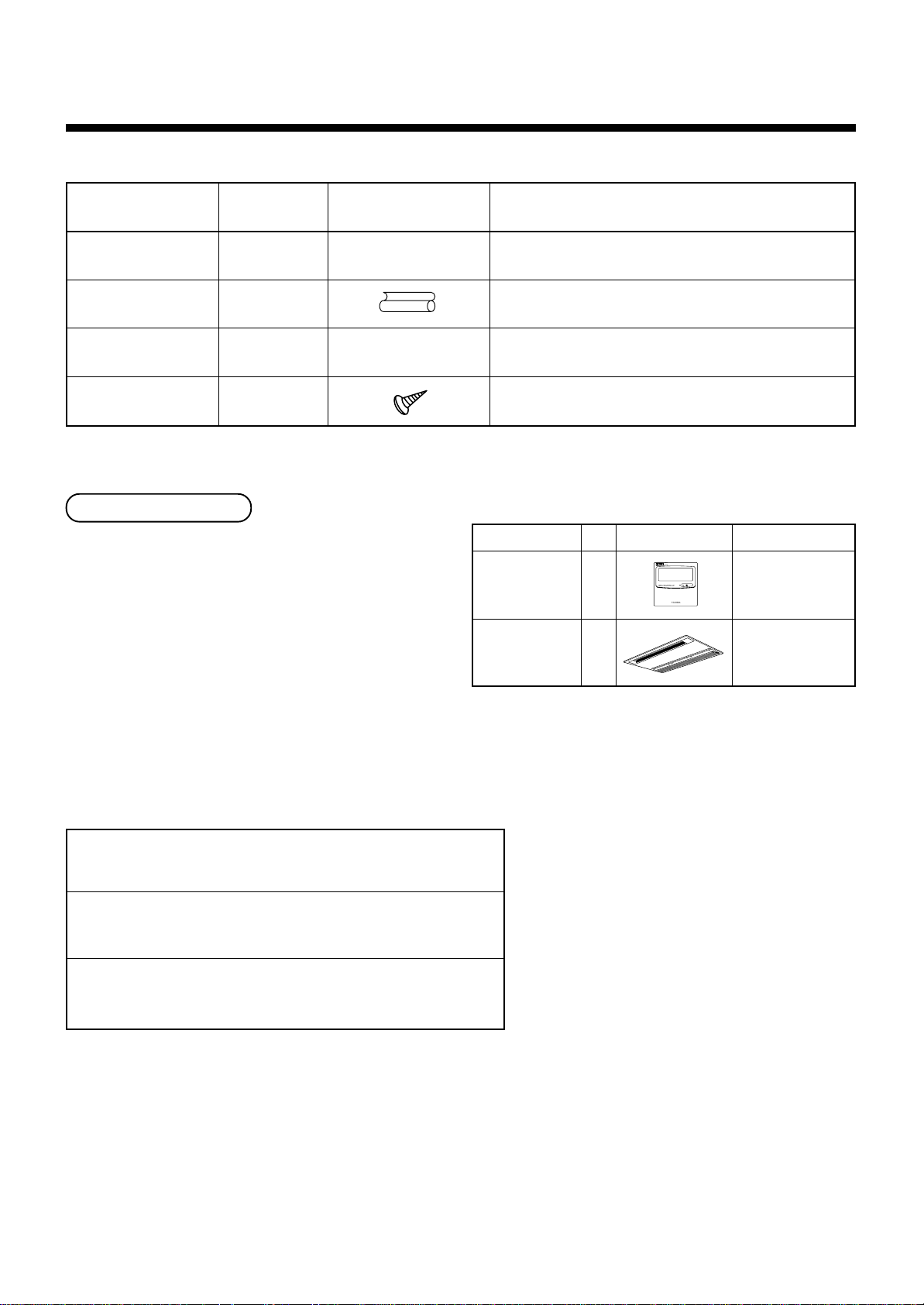
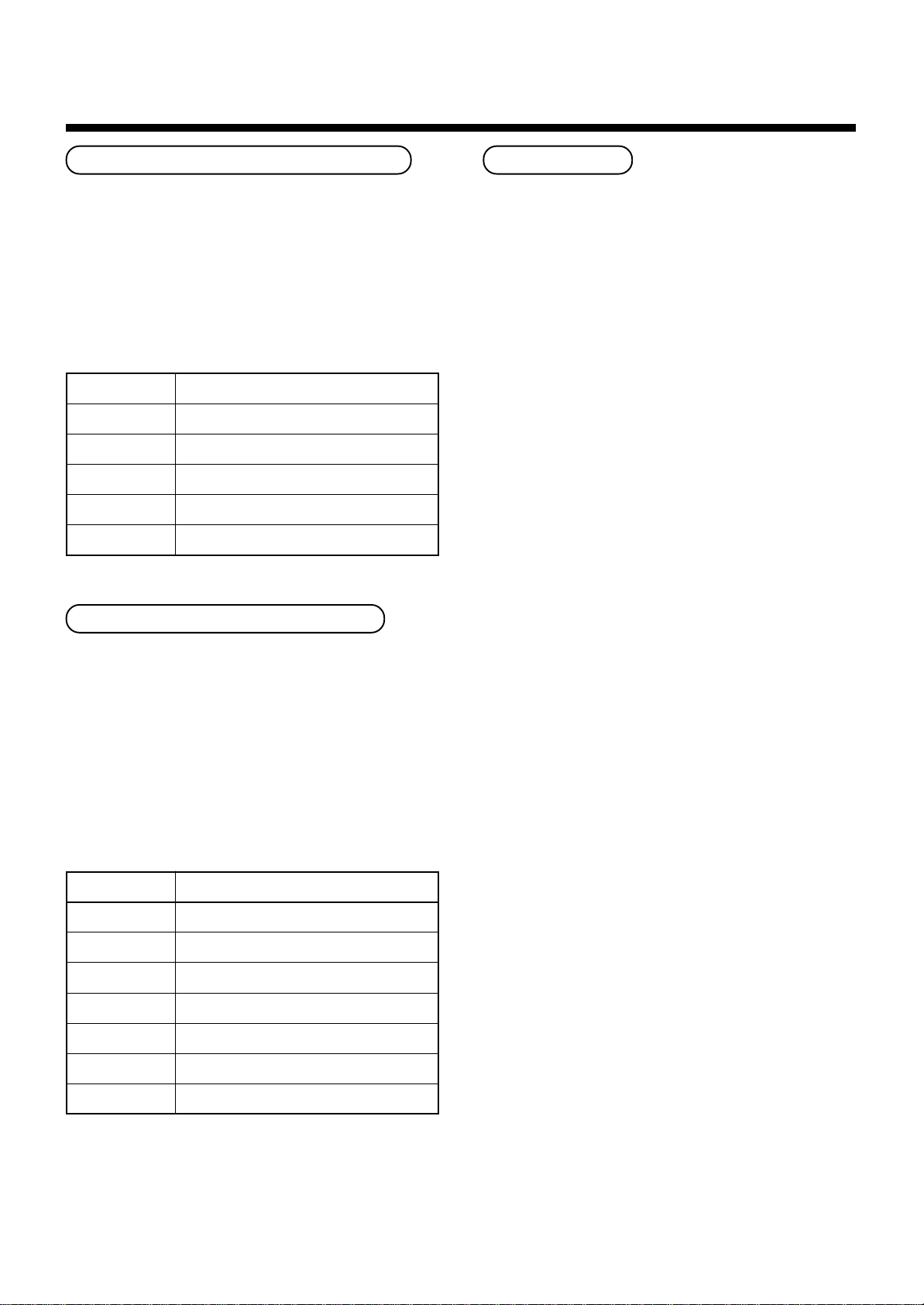
Accessory parts and Parts to be procured locally
H Accessory parts
Part name
Installation Manual
Heat Insulating pipe
Installation pattern
Pattern fixing screw
Q’ty
1
2
1
5
Shape
This manual
Refrigerant piping
• Piping material used for the conventional
refrigerant cannot be used.
• Use copper pipe with 0.8 mm or more thickness
for Ø6.4, Ø9.5, Ø12.7.
• Flare nut and flare works are also different from
those of the conventional refrigerant. Take out
the flare nut attached to the indoor unit of the air
conditioner, and use it.
—
Usage
(Be sure to hand over customers)
For heat insulating of pipe connecting section
For confirmation of ceiling opening and main unit position
Installation pattern fixing
<Separate sold parts>
Part name
Standard wired
remote controller
Ceiling panel
Q’ty
1
1
Shape Usage
Model
RBC-AMT21E
Model
RBC-UY135PG
H Parts to be procured locally
Connecting pipe (Liquid side)
(6.4mm (diam.), Nominal (diam.) 1/4” thick 0.8mm)
Connecting pipe (Gas side)
(12.7mm (diam.), Nominal (diam.) 3/8” thick 0.8mm)
Power supply cord
Cable 3-core 2.5mm
2
, in conformity with Design 60245 IEC57
1
Page 5
1
PRECAUTIONS FOR SAFETY
• Ensure that all Local, National and International regulations are satisfied.
• Read this “PRECAUTIONS FOR SAFETY” carefully before Installation.
• The precautions described below include the important items regarding safety. Observe them without fail.
• After the installation work, perform a trial operation to check for any problem.
Follow the Owner’s Manual to explain how to use and maintain the unit to the customer.
• Turn off the main power supply switch (or breaker) before the unit maintenance.
• Ask the customer to keep the Installation Manual together with the Owner’s Manual.
CAUTION New Refrigerant Air Conditioner Installation
• THIS AIR CONDITIONER ADOPTS THE NEW HFC REFRIGERANT (R410A) WHICH DOES NOT
DESTROY OZONE LAYER.
The characteristics of R410A refrigerant are ; easy to absorb water, oxidizing membrane or oil, and its pressure
is approx. 1.6 times higher than that of refrigerant R22. Accompanied with the new refrigerant, refrigerating oil
has also been changed. Therefore, during installation work, be sure that water, dust, former refrigerant, or
refrigerating oil does not enter the refrigerating cycle.
To prevent charging an incorrect refrigerant and refrigerating oil, the sizes of connecting sections of charging
port of the main unit and installation tools are charged from those for the conventional refrigerant.
Accordingly the exclusive tools are required for the new refrigerant (R410A).
For connecting pipes, use new and clean piping designed for R410A, and please care so that water or dust does
not enter. Moreover, do not use the existing piping because there are problems with pressure-resistance force
and impurity in it.
ENGLISH
CAUTION To Disconnect the Appliance from Main Power Supply.
This appliance must be connected to the main power supply by means of a switch with a contact separation of
at least 3 mm.
WARNING
• Ask an authorized dealer or qualified installation professional to install/maintain the air
conditioner.
Inappropriate installation may result in water leakage, electric shock or fire.
• Turn off the main power supply switch or breaker before attempting any electrical work.
Make sure all power switches are off. Failure to do so may cause electric shock.
• Connect the connecting wire correctly.
If the connecting wire is connected in a wrong way, electric parts may be damaged.
• When moving the air conditioner for the installation into another place, be very careful not
to enter any gaseous matter other than the specified refrigerant into the refrigeration cycle.
If air or any other gas is mixed in the refrigerant, the gas pressure in the refrigeration cycle becomes
abnormally high and it resultingly causes pipe burst and injuries on persons.
• Do not modify this unit by removing any of the safety guards or by by-passing any of the
safety interlock switches.
• Exposure of unit to water or other moisture before installation may cause a short-circuit of
electrical parts.
Do not store it in a wet basement or expose to rain or water.
2
Page 6
1
PRECAUTIONS FOR SAFETY
• After unpacking the unit, examine it carefully if there are possible damage.
• Do not install in a place that might increase the vibration of the unit.
• To avoid personal injury (with sharp edges), be careful when handling parts.
• Perform installation work properly according to the Installation Manual.
Inappropriate installation may result in water leakage, electric shock or fire.
• When the air conditioner is installed in a small room, provide appropriate measures to
ensure that the concentration of refrigerant leakage occur in the room does not exceed the
critical level.
• Install the air conditioner securely in a location where the base can sustain the weight
adequately.
• Perform the specified installation work to guard against an earthquake.
If the air conditioner is not installed appropriately, accidents may occur due to the falling unit.
• If refrigerant gas has leaked during the installation work, ventilate the room immediately.
If the leaked refrigerant gas comes in contact with fire, noxious gas may generate.
• After the installation work, confirm that refrigerant gas does not leak.
If refrigerant gas leaks into the room and flows near a fire source, such as a cooking range, noxious gas might
generate.
• Electrical work must be performed by a qualified electrician in accordance with the
Installation Manual. Make sure the air conditioner uses an exclusive power supply.
An insufficient power supply capacity or inappropriate installation may cause fire.
• Use the specified wires for wiring connect the terminals securely fix. To prevent external
forces applied to the terminals from affecting the terminals.
• Conform to the regulations of the local electric company when wiring the power supply.
Inappropriate grounding may cause electric shock.
• Do not install the air conditioner in a location subject to a risk of exposure to a combustible
gas.
If a combustible gas leaks, and stays around the unit, a fire may occur.
3
Page 7
2
SELECTION OF INSTALLATION PLACE
WARNING
• Install the air conditioner at enough strong place to withstand the weight of the unit.
If the strength is not enough, the unit may fall down resulting in injury.
• Perform a specified installation work to guard against an earth quake.
An incomplete installation can cause accidents by the units failing and dropping.
• Install the air conditioner at a height 2.5m or more from the floor.
If you insert your hands or others directly into the unit while the air conditioner operates, it is dangerous because
you may contact with revolving fan or active electricity.
CAUTION
• Do not install the air conditioner in a location subject to a risk of exposure to combustible gas.
Should the combustible gas leak and collect near the unit, fire may occur.
Upon approval of the customer, install the air conditioner in a place that satisfies the following
conditions.
• Place where the unit can be installed horizontally.
• Place where a sufficient servicing space can be ensured for safe maintenance and check.
• Place where drained water will not cause any problem.
Avoid installing in the following places.
• Place exposed to air with high salt content (seaside area), or place exposed to large quantities of sulfide gas (hot
spring). (Should the unit be used in these places, special protective measures are needed.)
• Place exposed to oil, vapor, oil smoke or corrosive gas.
• Place where organic solvent is used nearby.
• Place close to a machine generating high frequency.
• Place where the discharged air blows directly into the window of the neighboring house. (For outdoor unit)
• Place where noise of the outdoor unit is easily transmitted.
(When installing the air conditioner on the boundary with the neighbor, pay due attention to the level of noise.)
• Place with poor ventilation.
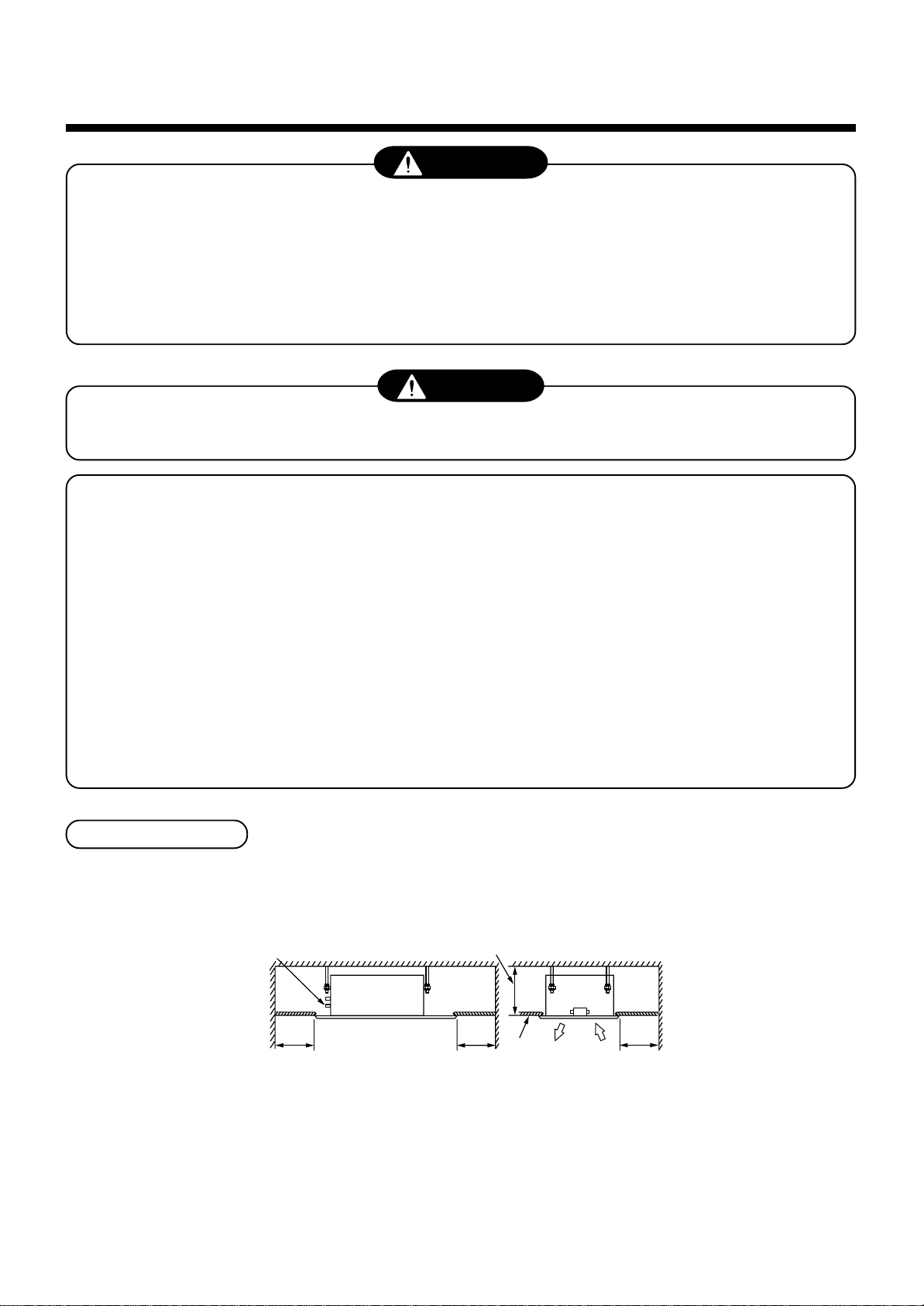
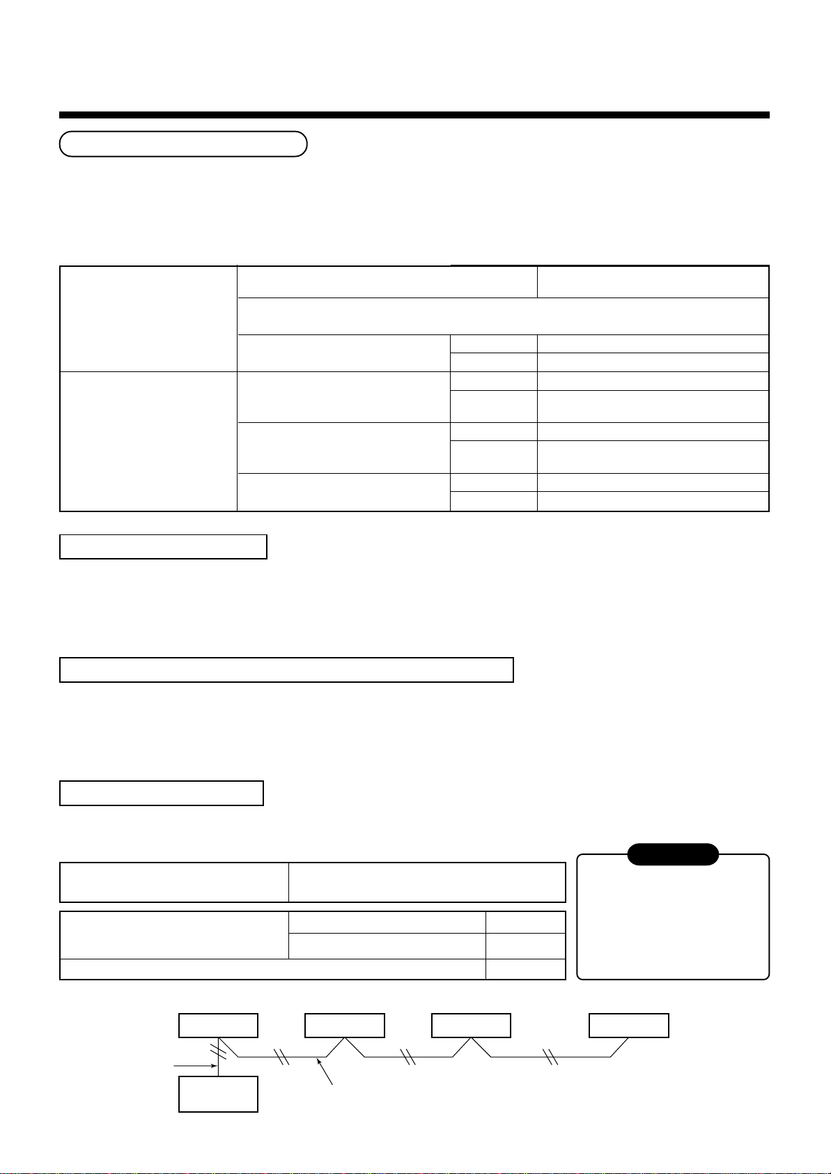
Installation space
Reserve space required to install the indoor unit and for service work.
Ceiling inside height :
Refrigerant piping port
100mm
and more
The lighting term setup of the filter sign (Notification of filter cleaning) of the remote controller can be changed
according to the condition of installation. If the room is not heated due to the installation place or construction of the
room, the detection temperature of heating can be raised.
For setup method, refer to “Change of lighting term of filter sign” and “To secure better effect of heating” in the
Applicable controls of this Manual.
245mm or more
100mm
and more
4
Ceiling
200mm
or more
Page 8
2
SELECTION OF INSTALLATION PLACE
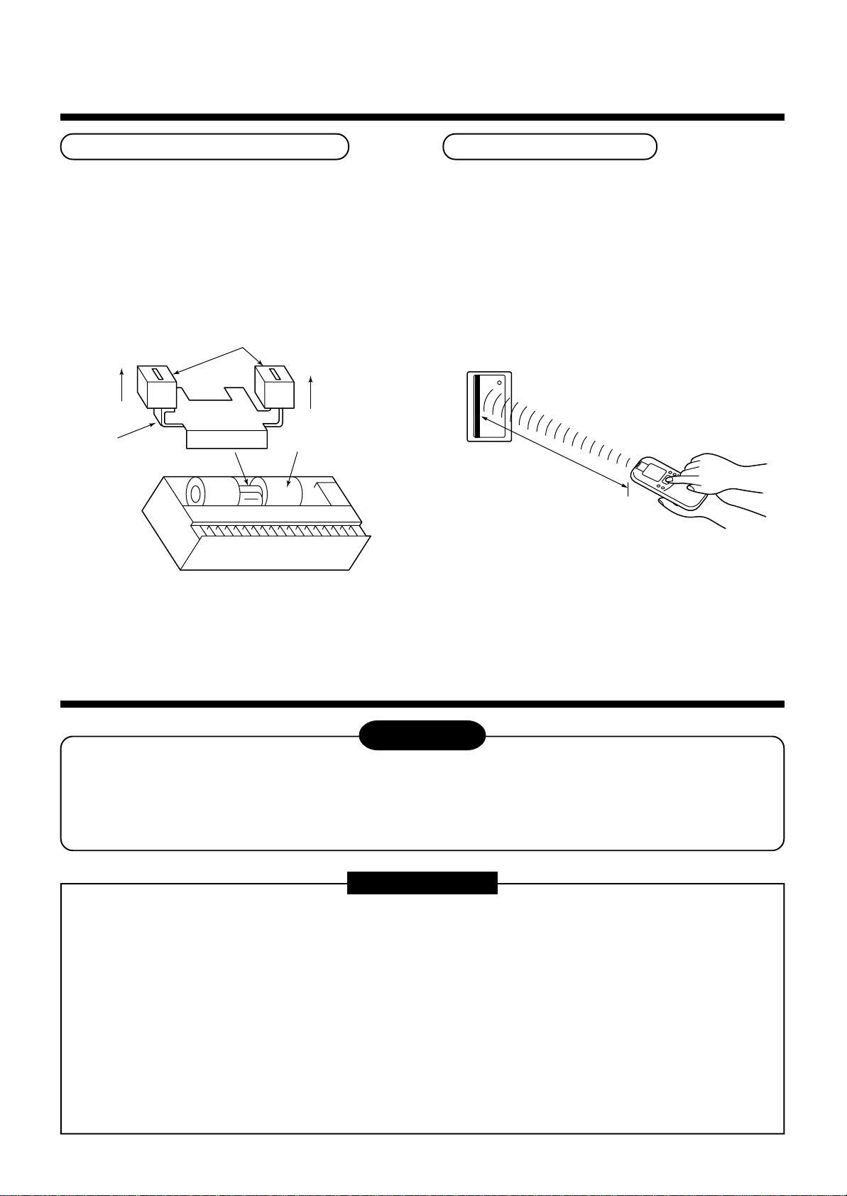
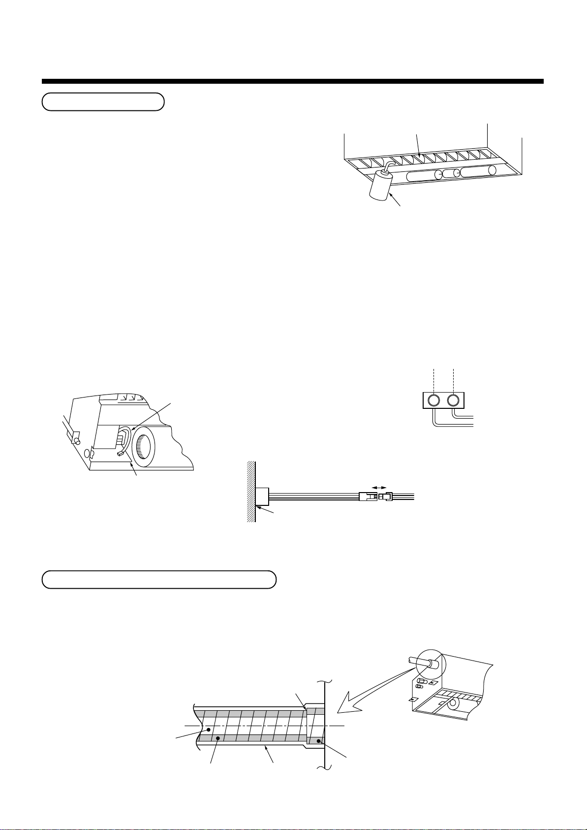
Removal of transporting rubbers
• Before installation of the indoor unit, remove the two
protective rubbers for transportation which are
inserted between the reinforcing bracket for the fan
motor and the casing.
(Hand over the protective rubbers for transportation
to the customers and ask to keep them because
they are used for transportation such as
reinstallation.)
Protective rubbers for transportation
(remove)
Pull upward to
remove.
Reinforcing bracket
Casing
In case of wireless type
The sensor of indoor unit with wireless remote
controller can receive a signal within approx. 8m.
Based upon it, determine a place where the remote
controller is operated and the installation place of the
indoor unit.
• To prevent a malfunction, select a place where is not
influenced by a florescent light or direct sunlight.
• Two or more (Up to 6 units) indoor units with
wireless remote controller can be installed in the
same room.
8m or less
3
INSTALLATION OF INDOOR UNIT
WARNING
Install the air conditioner certainly to sufficiently withstand the weight.
If the strength is insufficient, the unit may fall down resulting in human injury.
Perform a specified installation work to guard against strong wind or earthquake.
An incomplete installation can cause accidents by the units falling and dropping.
REQUIREMENT
Strictly comply with the following rules to prevent damage of the indoor units and human injury.
• Do not put a heavy article on the indoor unit. (Even units are packaged)
• Carry in the indoor unit as it is packaged if possible. If carrying in the indoor unit unpacked by necessity, be
sure to use buffering cloth, etc. to not damage the unit.
• To move the indoor unit, hold the hooking metals (4 positions) only.
Do not apply force to the other parts (refrigerant pipe, drain pan, foamed parts, or resin parts, etc.).
• Carry the package by two or more persons, and do not bundle it with PP band at positions other than
specified.
• The hanging bolt pitch on longitudinal direction is not divided at center with the ceiling opening size.
Therefore, check the relational position in the External view.
If relational position is incorrect, the check panel cannot be installed.
5
Page 9
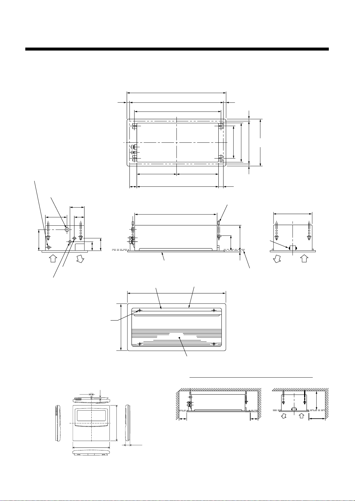
External view
Power connecting port
Drain pipe connecting port
(VP25)
225
200
150
100
85
120
110
Panel external dimension
Ceiling open dimension
1050
1010
890
455395
Center of panel
850
850
2020
330
400
50
Hanging bolt
4-M10 Arranged at site
23518
140
43020 20
470
Ceiling open dimension
Panel external dimension
Support
metal
400
Refrigerant pipe connecting port
(Gas side Ø9.5)
Refrigerant pipe connecting port
(Liquid side Ø6.4)
Panel mounting
hole 5 positions
• Wired remote controller
(RBC-AMT21E)
4
2.7
470
120
Ceiling panel
(Sold separately)
Discharge louver
Discharge port
1050
Air suction grille
Space necessary for installation and servicing
100
or more
Ceiling
bottom surface
100
or more
245
or more
200
or more
120
16
6
Page 10
3
INSTALLATION OF INDOOR UNIT
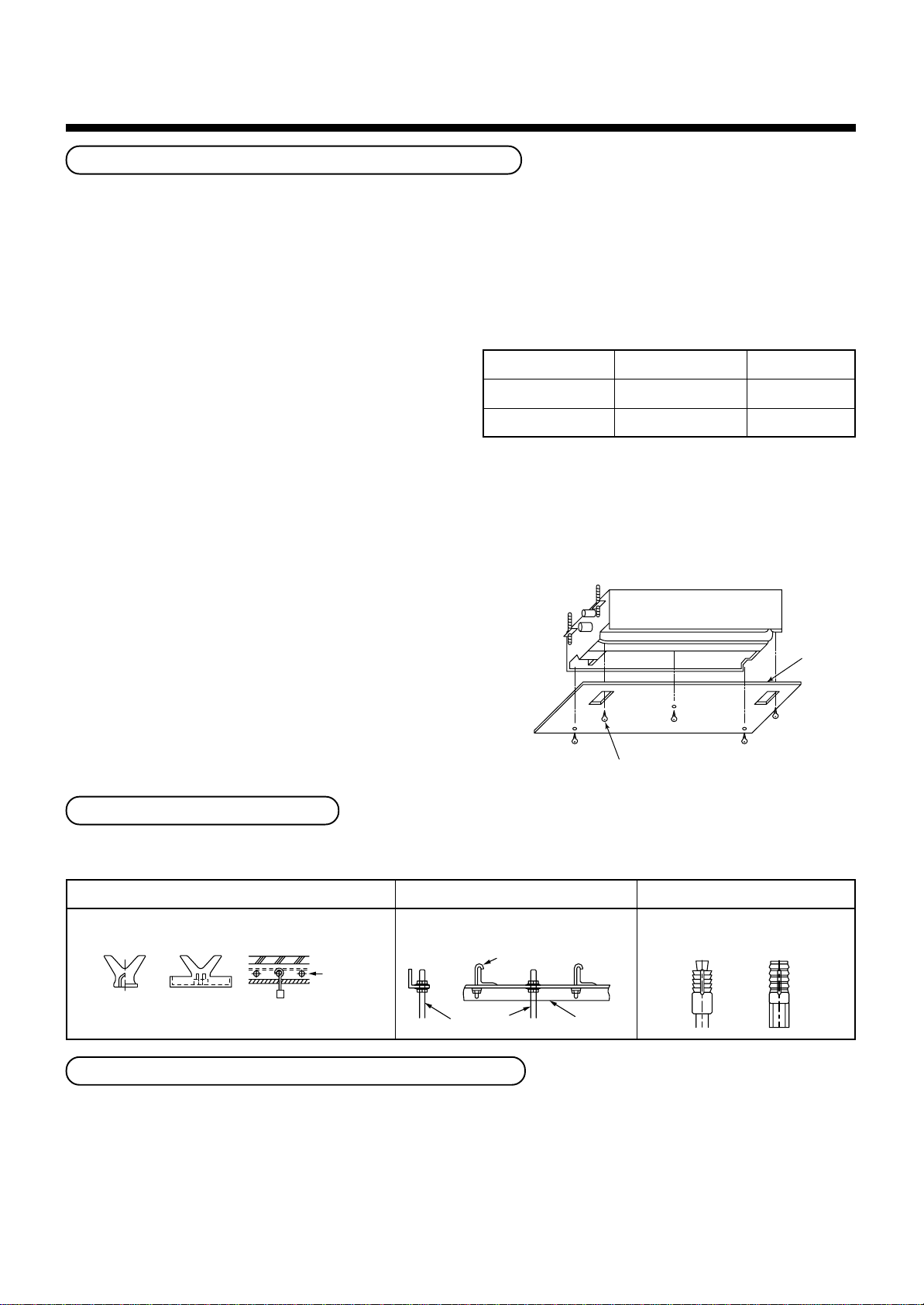
Ceiling opening and installation of hanging bolts
• Considering pipe/wire connecting work inside the ceiling after the indoor unit has been hanged, select an
installation place and determine piping direction.
• After installation place of the indoor unit has been determined, open the installation hole on the ceiling and install
the hanging bolts.
• For the ceiling opening size and the hanging bolt pitch, refer to the external view and the attached installation
pattern.
• If the ceiling has been already set up, draw the drain
pipe, refrigerant pipe, indoor/outdoor inter-unit cable,
cable for central control system, and remote
controller cable up to the position where pipes and
cables are to be connected before hanging the
Please procure the hanging bolts and nuts for
installation of the indoor unit at local site.
Hanging bolt
Nut
M10 or W3/8
M10 or W3/8
4 pieces
12 pieces
indoor unit.
Flat washer
M10
8 pieces
[How to use the attached installation pattern]
The installation pattern is attached inside of the package cap.
<In case of existing ceiling>
Use the installation pattern for positioning of the ceiling opening hole and the hanging bolt.
<In case of new ceiling>
Use the installation pattern for positioning of the opening hole
when setting up a new ceiling.
• Install the indoor unit after installation of the hanging bolts.
• Using the attached installation pattern fixing screws (M5 ×
20L: 4 pieces), attach the installation pattern to the indoor unit.
(Screwing to installation brackets of the ceiling panel)
• When setting up the ceiling, open a hole along the outside
dimension of the installation pattern.
Ceiling panel fixing screw
(Use the attached screws.)
Installation of hanging bolts
Use M10 hanging bolts (4 pcs, to be local procure).
Matching to the existing structure, set pitch according to size in the unit external view as shown below.
New concrete slab
Install the bolts with insert brackets or anchor
bolts.
Reinforcing
steel
(Blade type
bracket)
(Slide type
bracket)
Anchor bolt
(Pipe hanging
anchor bolt)
Steel flame structure
Use existing angles or install new
support angles.
Hanging bolt
Hanging bolt Support angle
Existing concrete slab
Use a hole-in anchors, hole-in
plugs, or a hole-in bolts.
Pattern sheet
Installation of remote controller (Sold separately)
For installation of the wired remote controller, follow the Installation Manual attached with the remote controller.
For installation of the wireless remote controller, follow to the Installation Manual attached to the remote controller.
• Do not put the remote controller on the place where is exposed to direct sunlight or near a stove, etc.
• Operate the remote controller, check the indoor unit surely receives the signal, and then install the remote
controller. (Wireless type)
• Install the remote controller 1m apart from the devices such as TV or stereo. (Image may be disturbed or noise
may be output.) (Wireless type)
7
Page 11
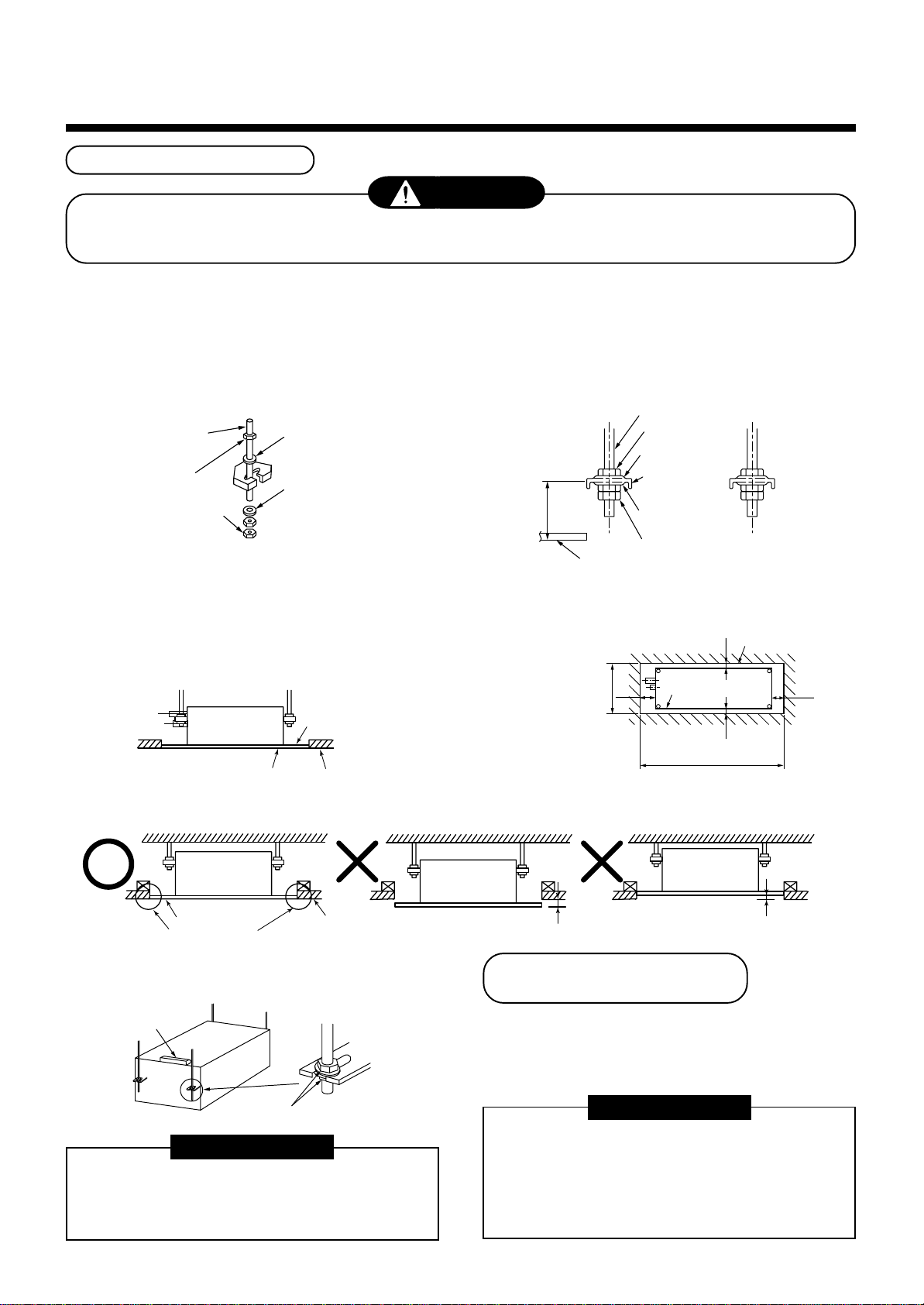
Installation of indoor unit
CAUTION
This unit is incorporated with drain pump and float switch. Never incline the main unit. Otherwise, malfunction
of the float switch may be caused resulting in water leakage.
• Attach the nut (M10 or W3/8: Procured locally) and the attached washer (Ø34mm) to the hanging bolt.
• Adjust nut position (lower side) so that clearance between (lower side) and the lower side of ceiling board is 137mm.
• Hang up the main unit by hanging nut of hanging bolt to T groove of hanging bracket of the indoor unit.
• Using the level vial, etc., check the horizontal level of the indoor unit.
• Using the installation pattern, check and adjust the positional relation between the indoor unit and ceiling opening
hole, and hanging-up height of the indoor unit.
695
Hanging bolt
Nut (Upper side)
Washer
(Upper side)
(Hanging bracket
main unit)
Washer
(Lower side)
Nuts (Lower side)
Outline of indoor unit
Opening part
2020
50110
Hanging bolt
(W3/8 or M10)
Nut
(W3/8 or M10)
Nut
(W3/8 or M10)
(1)Required those other than M10 flat washer at site.
(2)To prevent falling-off of bolt (safety), be sure to
set it just under the hanging bracket as shown
in the figure.
(1)
M10 flat washer
(Accessory)
(2)
M10 flat washer
(Accessory)
137mm
Lower surface of ceiling
• The used screws when attaching the installation pattern are used again to install the panel.
• Using the ceiling panel fixing screws, fix the installation pattern
under surface of the indoor unit.
• Fit the ceiling opening size to outside of the installation pattern.
Installation pattern
(Ceiling opening
dimension)
P0151, P0181 : 1160
Lower side of
installation pattern
Lower surface
of ceiling
P0241 : 1360
(Ceiling opening dimension)
• Match the bottom surface of ceiling and lower side of installation pattern on the same level.
Indoor unit
Lower side of
installation pattern
Match on the same level.
Lower surface
of ceiling
• Fix the indoor unit securely by tightening nut at
upper side.
Level vial
Indoor unit
Protruding : 0mm or more
Installation of ceiling panel
(Sold separately)
Install the ceiling panel according to Installation
Drawing : 3mm or less
Manual after piping/wiring work has completed.
Check that installation of indoor unit and ceiling
opening part is correct, and then install it.
Fix securely
REQUIREMENT
• Using a level vial, etc., confirm the horizontal
level of the indoor unit.
• Tighten the nut sufficiently, and fix it securely.
Connect the connecting sections of ceiling panel and
ceiling surface, and the ceiling panel and indoor unit
closely.
If there is clearance, air leakage generates
resulting in dewing or water leakage.
REQUIREMENT
Indoor unit
8
Page 12
4
DRAIN PIPING WORK
CAUTION
• Following the Installation Manual,
perform the drain piping work so that
Pipe material/Insulator and size
The following materials for piping work and insulating
process are procured locally.
water is properly drained, and apply a
heat insulation so as not to cause a dew.
Pipe material
Inappropriate piping work may result in
water leakage in the room and wet of
furniture.
Insulator
REQUIREMENT
• Be sure to perform heat insulation of the drain pipes of the indoor unit.
• Never forget to perform heat insulation of the connecting part with the
indoor unit. An incomplete heat insulation causes dewing.
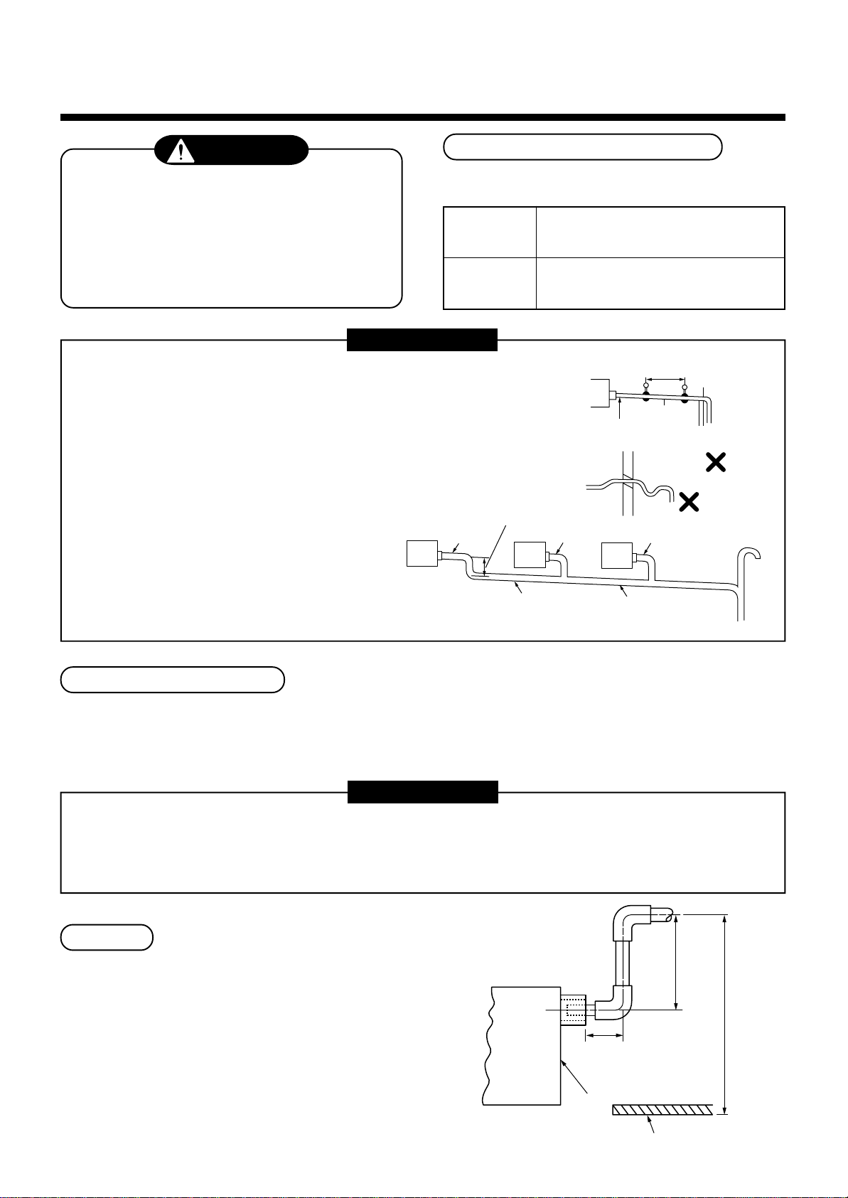
• Set the drain pipe with downward slope (1/100 or more), and do not
make swelling or trap on the piping. It may cause an abnormal sound.
• For length of the traversing drain pipe, restrict to 20m or less.
In case of a long pipe, provide support brackets with interval of
1.5 to 2m in order to prevent waving.
• Set the collective piping as shown in the right figure.
• Do not mount an air purge pipe,
otherwise drain water spouts
out resulted in water leak.
(Collective pipes)
As long as possible (10cm)
VP25
Hard vinyl chloride pipe VP25
(Outer diameter Ø32mm)
Foamed polyethylene foam, thickness:
10mm or more
VP25
Heat
insulator
1.5m to 2m
1/100 or more
downward
Arched
shape
Trap
VP25
Support
bracket
VP30 or more
Downward slope
1/100 or more
Connection of drain pipe
Connect hard vinyl chloride pipe to the drain piping port.
• Using adhesive agent for vinyl chloride, connect the hard vinyl chloride pipes certainly so that water does not leak.
• Apply adhesive agent around 40mm of the end of hard vinyl chloride pipe without unevenness, and then insert it
surely until it strikes to the drain socket.
REQUIREMENT
• Using adhesive agent for vinyl chloride, connect the hard vinyl chloride pipes certainly so that water does not leak.
• It requires several times to dry and harden the adhesive agent.
(Refer to Guide Manual of the adhesive agent.) In this time, be sure not to apply force to the connecting
section with the drain pipes.
Drain up
When a downward grading cannot be secured on the
drain pipe, a drain-up work is possible.
Rising up
• Set the height of the drain pipe within 350mm from
the bottom surface of the ceiling.
• Draw out the drain pipe within 150mm from the end
of the drain pipe connecting port of the indoor unit,
and then raise it vertically.
• After the drain pipe has been raised, set a grading
so that it is immediately bent downward.
100mm
or less
Indoor unit
Underneath of ceiling
9
150mm or less
Rising up 350mm or less
Page 13
Check the draining
Black White
Black
Black
BlackWhite
Pull out
Float
switch
P.C. board connector CN030 (Red)
After drain piping work, check that water drain is
properly performed and water does not leak from the
Air outlet
connecting part of the pipes. In this time, check also
there is no abnormal sound of the motor of the drain
pump. Be sure to check draining when installed in the
heating period.
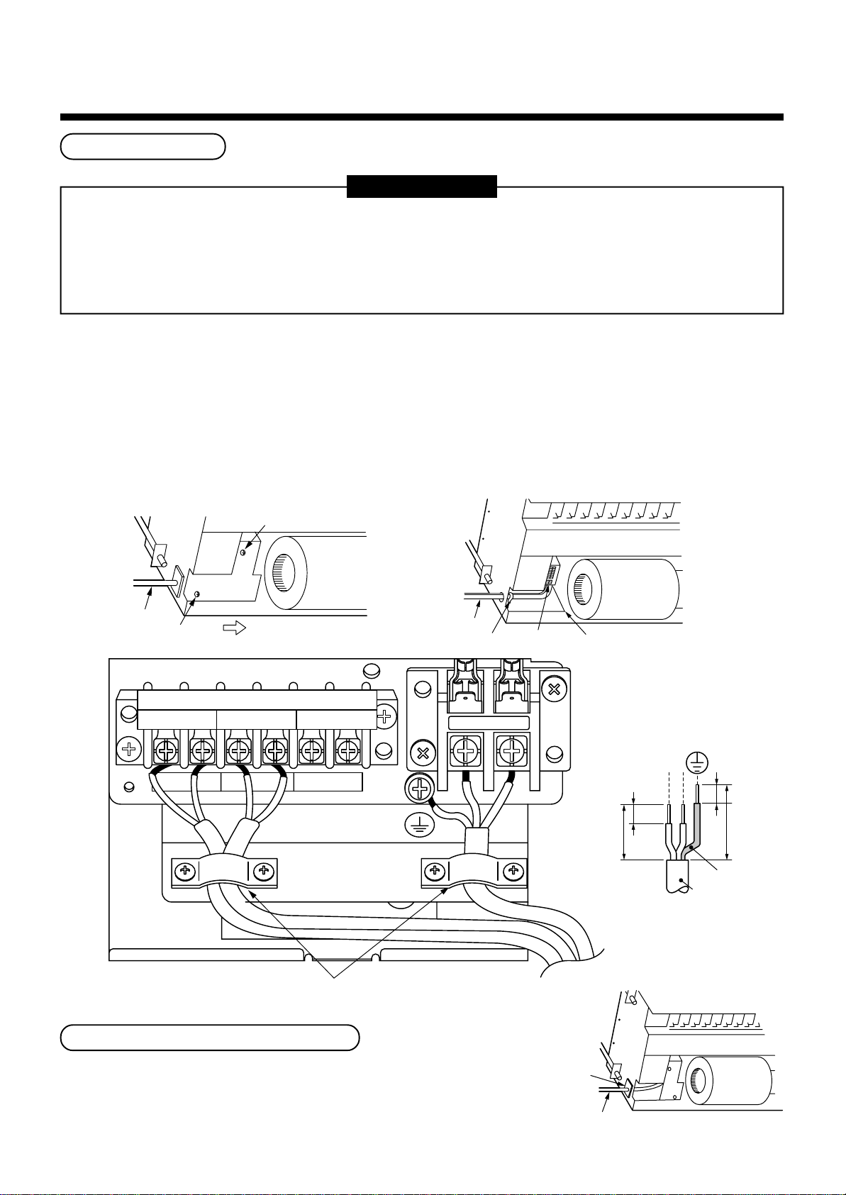
When the electric work has finished:
Pitcher
• Before installing a panel, pour water (500cc) as shown in the following figure, check water is drained from the
drain pipe connecting port in COOL mode, and then check there is no water leak from the drain pipes.
When the electric work has not finished:
• Pull out the float switch connector (2P: White). (In this time, be sure to check the power is turned off.)
• Connect the single-phase 220-240V 50Hz (or 220V 60Hz) power to the terminal blocks R (L) and S (N).
(Never apply 220-240V to (A), (B), (U1),and (U2), otherwise a trouble of P.C. board occurs.)
• When the power is turned on, the drain pump motor drives automatically. Check water is drained from the drain
pipe connecting port, and then check there is no water leak from the drain pipes.
• After check of draining and water leak, turn off the power supply, attach the float switch connector to the original
position.
Float switch connector (2P, White)
(Lead wire color : Black)
R(L) S(N)
Electric parts box
Heat insulating of pipe connecting part
• Be sure to apply heat insulating securely to the pipe connecting part.
• Be sure to tape surely the butting part of the heat insulator
at the main unit side and at site so that no clearance generates.
Butt heat insulator without clearance.
Single phase 220-240V, 50Hz
220V, 60Hz
Hard vinyl
chloride pipe
(Required at site)
Heat insulator
(Required at site)
Using tape,
fix the heat insulator.
10
Heat insulator
(Main unit side)
Page 14
5
REFRIGERANT PIPING
WARNING
• If refrigerant gas has leaked during the installation work, ventilate the room immediately.
• If the leaked refrigerant gas comes in contact with fire, noxious gas may generate.
• After the installation work, confirm that refrigerant gas does not leak.
• If refrigerant gas leaks into the room and flows near a fire source, such as a cooking range, noxious gas may
generate.
REQUIREMENT
When the refrigerant pipe is long, set the support brackets to fix the pipe with 2.5 to 3m intervals. If the pipe is
not fixed, abnormal sound may generate.
Be sure to use the flare nuts attached to the indoor unit or those for R410A.
Permissible pipe length and permissible height difference
They are different according to the used outdoor unit. For details, refer to the Installation Manual attached to the
outdoor unit.
Piping material and dimensions
Piping material
Model MMU-
Pipe size (mm)
• Use a clean and new pipe, and check that impurity such as dust, oil, moisture, etc. does not adhere in the pipe.
Gas side
Liquid side
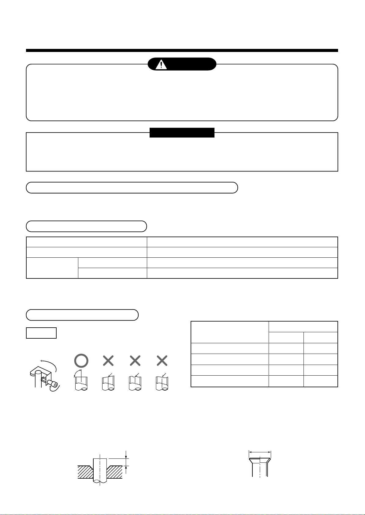
Pipe forming/End positioning
Flaring
1. Cut the pipe with a pipe cutter.
90˚
2. Insert a flare nut into the pipe, and flare the pipe.
As the flaring sizes of R410A differ from those of
refrigerant R22, the flare tools newly manufactured
for R410A are recommended.
However, the conventional tools can be used by
adjusting projection margin of the copper pipe.
Obliquity Roughness Warp
B
Phosphor deoxidization joint-less pipe for air conditioner
AP0071YH to AP0121YH
Ø9.5
Ø6.4
• Flaring diam. meter size : A (Unit : mm)
+0
A
Outer diam. of copper pipe
6.4
9.5
12.7
15.9
In case of flaring for R410A with the conventional
*
flare tool, pull it out approx. 0.5 mm more than that
for R22 to adjust to the specified flare size.
The copper pipe gauge is useful for adjusting
projection margin size.
A
R410A R22
9.1 9.0
13.2 13.0
16.6 16.2
19.7 19.2
- 0.4
11
Page 15
• Projection margin in flaring : B (Unit : mm)
Rigid (Clutch type)
Outer diam. of
copper pipe
6.4
9.5
12.7
15.9
R410A tool used
R410A R22
0 to 0.5 (Same as left)
0 to 0.5 (Same as left)
0 to 0.5 (Same as left)
0 to 0.5 (Same as left)
Imperial (Wing nut type)
Conventional tool used
R410A R22
1.0 to 1.5 0.5 to 1.0
1.0 to 1.5 0.5 to 1.0
1.0 to 1.5 0.5 to 1.0
1.0 to 1.5 0.5 to 1.0
Airtight test/Air purge, etc.
For airtight test, air purge, addition of refrigerant, and
gas leak check, follow the Installation Manual attached
to the outdoor unit.
REQUIREMENT
Be sure to use the tool such as charge hose
exclusive to R410A.
Do not turn on the power until the airtight test and
the vacuuming have finished. (If turning on the
power, the incorporated PMV is closed fully and the
period until the vacuuming finishes elongates.
Outer diam. of copper pipe
6.4
9.5
12.7
15.9
R410A R22
1.5 to 2.0 1.0 to 1.5
1.5 to 2.0 1.0 to 1.5
2.0 to 2.5 1.5 to 2.0
2.0 to 2.5 1.5 to 2.0
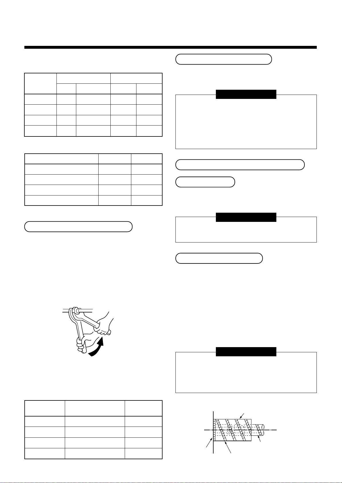
Connection of refrigerant pipe
Connect all the refrigerant pipes with flare connecting
work.
• Since the atmospheric pressure only is sealed
as the sealing gas, it is not abnormal that
“Pushu…” sound is not heard when the flare
nut is removed.
• Be sure to use a double spanner for pipe
connecting work of the indoor unit.
Open fully valves of the outdoor unit
Gas leak check
Check with a leak detector or soap water whether gas
leaks or not, from the pipe connecting section or cap of
the valve.
REQUIREMENT
Use a leak detector manufactured exclusively for
HFC refrigerant (R410A, R134a, etc.).
Heat insulating process
Perform heat insulating for pipes at liquid side and gas
side separately.
In cooling time, temperature at both liquid and gas sides
becomes lower.
Therefore, perform heat insulating process sufficiently
to avoid dewing.
• For heat insulator of pipe at gas side, be sure to use
one with heat-resisting temp.120°C or more.
• Using the attached heat insulating pipe, perform heat
insulating process securely for pipe connecting part of
the indoor units without clearance.
Work using double spanner
• Refer to the following table for tightening torque.
Connecting pipe
outer dia. (mm)
Ø6.4
Ø9.5
Ø12.7
Ø15.9
Tightening torque
(N•m)
14 to 18 (1.4 to 1.8 kgf•m)
33 to 42 (3.3 to 4.2 kgf•m)
50 to 62 (5.0 to 6.2 kgf•m)
68 to 82 (6.8 to 8.2 kgf•m)
Re-tightening
torque (N•m)
18 (1.8 kgf•m)
42 (4.2 kgf•m)
50 (5.0 kgf•m)
68 (6.8 kgf•m)
REQUIREMENT
Apply the thermal insulation to the pipe connecting
section of the indoor unit securely up to the root
without exposure of the pipe.
(The pipe exposed to the outside causes water leak.)
Set notching upward.
Pipe side
Main unit
Attached heat insulating pipe
12
(Required at the site)
Page 16
6
ELECTRIC WORK
WARNING
1. Using the specified wires, ensure to connect the wires, and fix wires securely so that the
external strength of the wires do not transmit to the connecting part of the terminals.
Incomplete connection or fixation may cause a fire, etc.
2. Be sure to connect earth wire. (Grounding work)
Do not connect the earth wire to gas pipe, city water pipe, lightning rod, or the earth wire of
telephone.
Incomplete grounding causes an electric shock.
3. For electric work, strictly follow to the Local Regulation in each country and the Installation
Manual, and use an exclusive circuit.
Capacity shortage of power circuit or incomplete installation may cause an electric shock or a fire.
CAUTION
Be sure to install an earth leakage breaker.
If an earth leakage breaker is not installed, an electric shock may be caused.
REQUIREMENT
• For power supply wiring, strictly conform to the Local Regulation in each country.
• For wiring of power supply of the outdoor units, follow to the Installation Manual of each outdoor unit.
• Never connect 220–240V power to the terminal blocks (A, B, U1, U2, X, Y, etc.) for control wiring.
(Otherwise, the system will be failed.)
• Perform the electric wiring so that it does not come to contact with the high-temperature part of the pipe.
The coating may melt resulted in an accident.
• After connecting wires to the terminal blocks, provide a trap and fix wires with the wire clamp.
• Store the refrigerant piping line and control wiring line in the same line.
• Do not turn on the power of the indoor unit until vacuuming of the refrigerant pipes completes.
13
Page 17
Power supply specifications
Power supply cord and communication wires are procured locally.
For the power supply specifications, follow to the table below. If capacity is little, it is dangerous because overheat or
seizure may be caused.
For specifications of the power capacity of the outdoor unit and the power supply wires, refer to the Installation
Manual attached to the outdoor unit.
220–240V ~ 50Hz
220V
Twist wire : 2.0 mm²
Twist wire : 3.5 mm²
Twist wire : 0.5 to 2.0 mm²
~ 60Hz
2
2
2
Indoor unit power supply (*1)
Communication line
Power supply
Power supply switch/Earth leakage breaker or power supply wiring/fuse rating for
indoor units should be selected by the accummulated total current values of the indoor units.
Power supply wiring
Indoor/Outdoor inter-unit wiring (*2)
Central control line wiring (*3)
Remote controller wiring (*4)
20m or less
50m or less
Q’ty
Wire size
Q’ty
Wire size
Q’ty
Wire size
(Up to 1000m) Twist wire : 1.25 mm²
(Up to 2000m) Twist wire : 2.00 mm²
(Up to 1000m) Twist wire : 1.25 mm²
(Up to 2000m) Twist wire : 2.00 mm²
Indoor unit power supply (*1)
• For the power supply of the indoor unit, prepare the exclusive power supply separated from that of the outdoor unit.
• Arrange the power supply, earth leakage breaker, and main switch of the indoor unit connected to the same
outdoor unit so that they are commonly used.
• Power supply cord specification : Cable 3-core 2.5mm², in conformity with Design 60245 IEC 57.
Indoor/Outdoor inter-unit wiring, Central controller wiring (*2) (*3)
• 2-core with polarity wires are used for the Indoor/Outdoor inter-unit wiring and Central controller wiring.
• To prevent noise trouble, use 2-core shield wire.
• The length of the communication line means the total length of the inter-unit wire length between indoor and
outdoor units added with the central control system wire length.
Remote controller wiring (*4)
• 2-core with non-polarity wire is used for wiring of the remote controller wiring and
group remote controllers wiring.
CAUTION
Remote controller wiring, remote
controller inter-unit wiring
Total wire length of remote controller
wiring and remote controller inter-unit
wiring = L + L1 + L2 + … Ln
Total wire length of remote controller inter-unit wiring = L1 + L2 + … Ln
Indoor unit
Remote
controller
wiring
Remote
controller
Twist wire: 0.5mm2 to 2.0mm2 × 2
In case of wired type only
In case of wireless type included
Indoor unit
L1 L2 Ln
Remote controller inter-unit wiring
Indoor unit Indoor unit
Up to 500m
Up to 400m
Up to 200m
(Max. 8 units)
The remote controller wire
(Communication line) and
AC220–240V wires cannot be
parallel to contact each other and
cannot be stored in the same
conduits. If doing so, a trouble
may be caused on the control
system due to noise, etc.
14
Page 18
6
ELECTRIC WORK
Cable connection
REQUIREMENT
• As the remote controller cable has no polarity, there is no problem if connections to indoor unit terminal blocks
A and B are reversed.
• Be sure to pass the cable through the bushing of cable connection port of the indoor unit.
• Keep a margin (approx. 100m) on a cable to hang down the electric parts box at servicing, etc.
• The low-voltage circuit is provided for the remote controller. (Do not connect high-voltage circuit.)
How to remove cover of the electric parts box
• Take off the screw A fixing the electric parts box, and then loosen the screw B a little. Remove cover of the electric
parts box by pushing the cover toward arrow direction C.
• Fasten the screws of the terminal block tightly and fix the wires with cord clamp attached to the electric parts box.
(Do not apply tension to connecting part of the terminal block.)
• Be sure to make a loop on the connecting part of the wire to the electric parts storing section of the indoor unit;
otherwise the electric storing section cannot be pulled out downward at service time.
• Mount cover of the electric parts box so as not to pinch the wires.
Screw A
Wire
Screw B
FOR INTER-UNIT FOR AI-NET
U1 U2 A B X Y
C
DON’T APPLY 220-240V
FOR REMOTE CONTROL
Wire
Cord clamp
R(L) S(N)
Terminal block
Electric parts box
10
30
LN
10
70
Earth line
Connecting cable
Cable clamp
Treating of wiring connecting port
• As shown on the figure, seal the wire connecting port with heat
insulator.
If sealing is insufficient, dewing is caused in the electric parts box.
15
Heat insulator
(Required at site)
Cable
Page 19
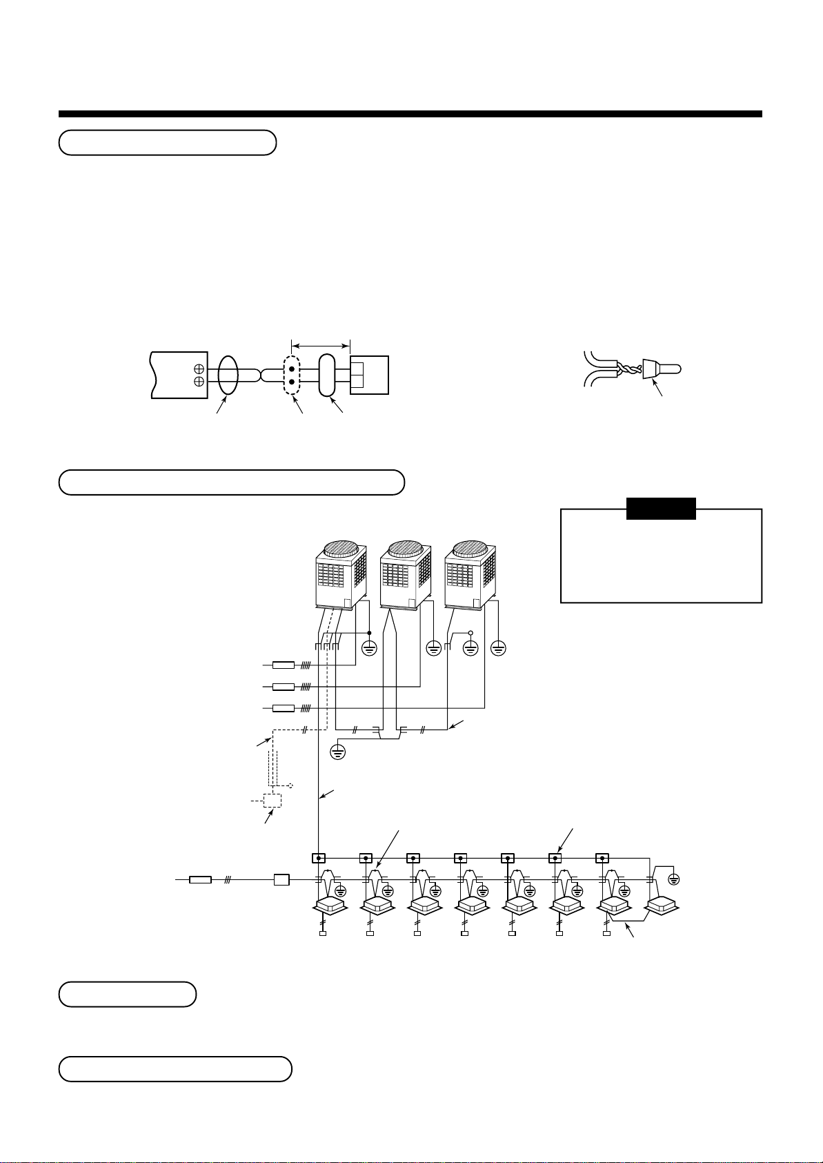
Remote controller wiring
Wire from remote
controller or sensor
Remote controller wiring
Wire joint
• Strip off approx. 14mm cover of the wire to be connected.
• Twist wire of the remote controller to be connected with wire of the remote controller unit (or sensor), and press-fit
them with a wire joint. (Wire joints (White: 2 pieces) are included in the accessory of the main remote controller
(sold separately) or wireless remote controller kit (sold separately).)
• As the remote controller wire has no polarity, there is no problem if connections to indoor unit terminal blocks A
and B are reversed.
<Wiring diagram>
Terminal block
for remote controller
wiring of indoor unit
A
B
Approx. 200mm
W
B
W : White
B : Black
Remote
controller unit
or sensor part
Remote controller wire
(Local procure)
Connecting
part
Wire from remote controller unit
or sensor
Wiring between indoor and outdoor units
Header unit Follower unit
Earth leakage breaker
Outdoor power supply
3-phase
380–415V, 50Hz
380V, 60Hz
Central control line wire
Power supply
220–240V
220V ~ 60Hz
Indoor power supply
220–240V
220V ~ 60Hz
~ 50Hz
(Open)
~ 50Hz
Remote controller,
for central control, etc.
Earth leakage breaker
Switch
Connection of shield
wire closed terminal
Indoor/Outdoor inter-unit wire
Connection of shield
wire closed terminal
An outdoor unit connected
with indoor/outdoor inter-unit
wire becomes automatically
the header unit.
(Earth)
Earth
Inter-unit wire between outdoor units
Pull box
NOTE
(Earth)
Address setup
Set up the addresses according to the Installation Manual attached to the outdoor unit.
Wiring on the ceiling panel
According to the Installation Manual of the ceiling panel, connect the connector.
16
Indoor unit
(Remote controller group operation)
Page 20
7
APPLICABLE CONTROLS
NOTIFICATION
When using the equipment at the first time, it will take a lot of time that the remote controller accepts an
operation after power was on. However, it is not a trouble.
• Automatic address
• While automatic addressing, the operation cannot be performed on the remote controller.
• For automatic addressing, Max. 10 minutes (generally, approx. 5 minutes) are required.
• When power will be turned on after finish of automatic addressing;
• It will require Max. 10 minutes (generally, approx. 3 minutes) that outdoor unit starts operation after power
was on.
As all have been set to [Standard] at the shipment, change the setup of the indoor unit if necessary.
To change the setup, use the main remote controller (wired remote controller).
* The setup change for wireless remote controller, sub remote controller, or remote controller-less system
(Central control remote controller only is provided.) is impossible. In these cases, prepare and mount a
separate main remote controller.
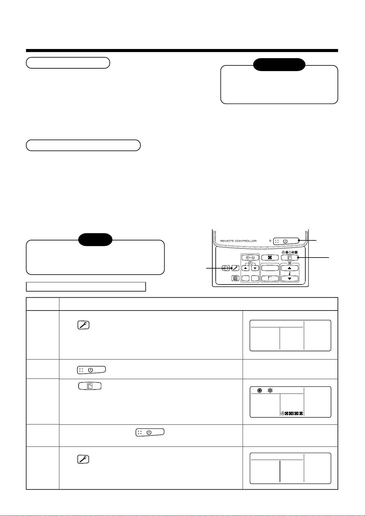
Exchange of applicable control setup
Basic operation procedure for setup exchange
Change the setup while operation of the equipment stops.
(Be sure to stop the operation of a set.)
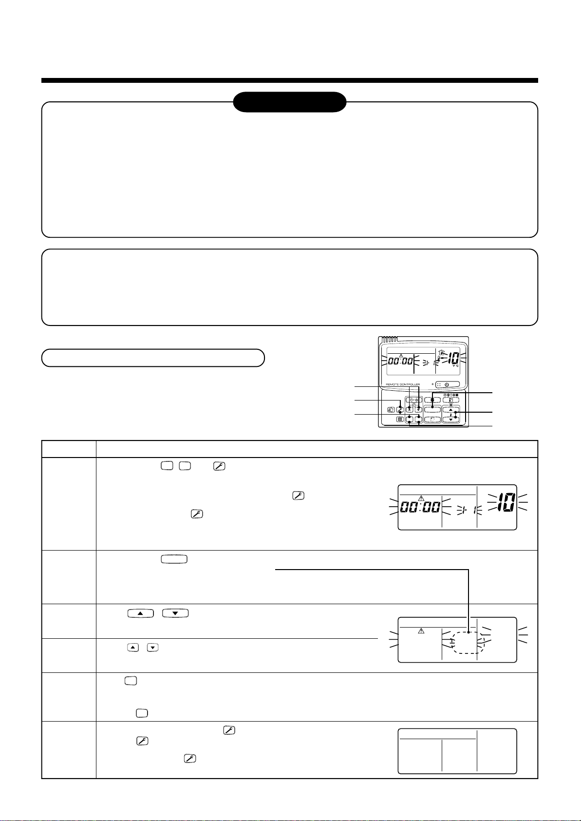
Procedure
SET
, CL, and buttons simultaneously for 4 seconds or more, after a while, the display part
UNIT
button, the indoor unit No. in the group control is displayed successively. Select an
1
2
3
When pushing
flashes as shown in the figure.
Check that the displayed item code is [10].
• If the item code indicates other than [10], push
the display, and then retry the operation from the first step.
(For some time after button has been pushed, the operation of
the remote controller cannot be accepted.)
(In a group control, the firstly displayed
indoor unit No. becomes the header unit.)
Every pushing
indoor unit of which setup to be changed.
In this time, the position of the indoor unit of which setup to be
changed can be confirmed because the fan and the flap of the
selected indoor unit work.
Using , buttons of set temperature, specify the item
code [**].
Using , buttons of timer time, select set data [
4
UNIT No.
R.C. No.
UNIT
CODE No.
2
3
4
6
1
SET DATA
CL
SET
5
Description
button to erase
(* The display changes according to the indoor unit model.)
].
****
*
** **
UNIT No.
R.C. No.
UNIT No.
** **
R.C. No.
CODE No.
CODE No.
**
5
6
SET
Push
• To change the setup of an indoor unit other than the selected one, start operation from Procedure
• To change the setup of another setup in the selected indoor unit, start operation from Procedure
Pushing
When the setup finished, push button. (The setup is determined.)
Pushing
normal stop status.
(For some time after button has been pushed, the operation of
the remote controller cannot be accepted.)
button. In this time, if the display changes from flashing to lighting, the setup completes.
CL
button clears the set up contents which have been already set. In this case, retry from Procedure 2.
button deletes the display and returns the status to
17
2
.
3
.
Page 21
Change of lighting term of filter sign
Group control
According to the installation condition, the lighting term
of the filter sign (Notification of filter cleaning) can be
changed.
Follow to the basic operation procedure
(1 → 2 → 3 → 4 → 5 → 6 ).
• For the item code in Procedure 3 , specify [01].
• For the [Set data] in Procedure 4 , select the setup
data of filter sign lighting term from the following
table.
Setup data
0000
0001
0002
0003
0004
Filter sign lighting term
None
150H (At shipment from factory)
2500H
5000H
10000H
To secure better effect of heating
In a group control, a remote controller can control up
to maximum 8 units.
• For cabling procedure and cables of the individual
line (Identical refrigerant line) system, refer to
“Electric work” in this Manual.
• Cabling between indoor units in a group is performed
in the following procedure.
Connect the indoor units by connecting the remote
controller inter-unit cables from the remote controller
terminal blocks (A, B) of the indoor unit connected
with a remote controller to the remote controller
terminal blocks (A, B) of the other indoor unit.
(No polarity)
• For address setup, refer to the Installation Manual
attached to the outdoor unit.
When it is difficult to obtain satisfactory heating due to
installation place of the indoor unit or structure of the
room, the detection temperature of heating can be
raised. Also use a circulator, etc. to circulate heat air
near the ceiling.
Follow to the basic operation procedure
(1 → 2 → 3 → 4 → 5 → 6 ).
• For the item code in Procedure 3 , specify [06].
• For the set data in Procedure 4 , select the setup
data of shift value of detection temperature to be set
up from the table below.
Setup data
0000
0001
0002
0003
0004
0005
Detection temp shift value
No shift
+1°C
+2°C (At shipment from factory)
+3°C
+4°C
+5°C
0006
+6°C
18
Page 22
8
TEST RUN
Before test operation
• Before turning on the power supply, carry out the following items.
1) Using 500V-megger, check there is 1MΩ or more between
the terminal block of the power supply and the earth. If 1MΩ
or less is detected, do not run the unit.
2) Check that all the valves of the outdoor unit are fully opened.
• Never push the electromagnetic contactor to carry out a forced test operation.
(It is very dangerous because a protective device does not work.)
How to execute test operation
• To carry out a fan operation in a single indoor unit, turn off the power once, short CN72 on P.C. board, and then
turn on the power again. (Start the unit in FAN mode.) In this case, do not forget to clear short-circuit of CN72 after
test operation.
• Using the remote controller, check the operation in the usual operation. For the operation procedure, refer to the
attached Owner’s Manual.
A forced test operation can be executed in the following procedure under condition of thermo-OFF of room
temperature.
In order to prevent a serial operation, the forced test operation is released after 60 minutes and returns to the
usual operation.
To protect the compressor at
starting time, keep power-ON
condition before 12 hours or more.
NOTE
Do not use a forced operation in cases other
than test operation because it applies an
excessive load to the air conditioner.
In case of wired remote controller
1, 5
WARNING
CL
SET
2, 4
UNIT
3
Procedure
1
2
3
4
5
Description
Keep button pushed for 4 seconds or more. [TEST] is
displayed on the display part and the selection of mode in the test
mode is permitted.
Push button.
Using button, select the operation mode, [COOL] or [HEAT].
• Do not run the air conditioner in a mode other than [COOL] or [HEAT].
• The temperature controlling function does not work during test
operation.
• The detection of error is performed as usual.
After the test operation, push button to stop the operation.
1
(Display part is same as procedure
Push button to cancel (release from) the test operation mode.
([TEST] disappears on the display part and the status returns to a
normal stop status.)
)
TEST
19
Page 23
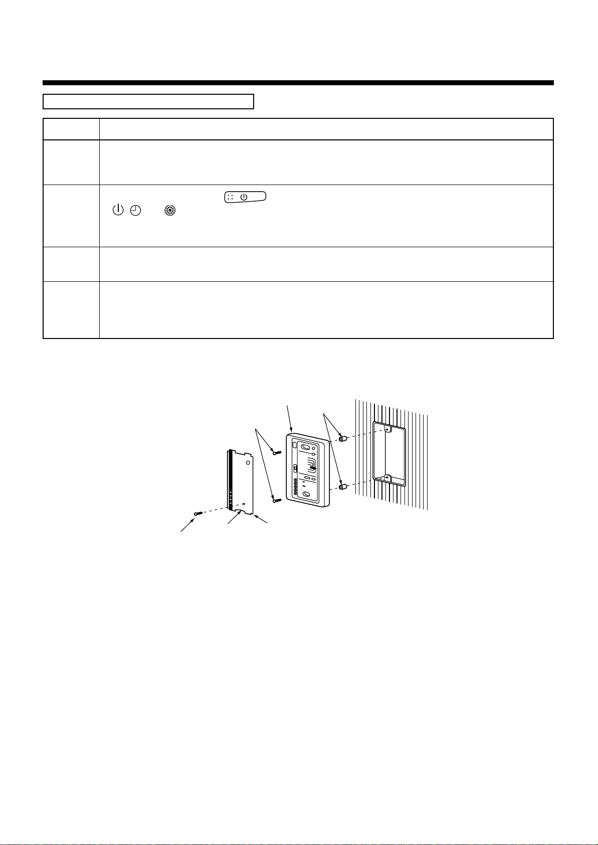
In case of wireless remote controller
Procedure
1
2
3
4
Description
Remove a small screw which fixes the nameplate of the receiver unit.
Remove the nameplate of the sensor section by inserting a minus screwdriver, etc into the notch at the bottom
of the plate, and set the Dip switch to [TEST RUN ON].
Execute a test operation with button on the wireless remote controller.
•
, , and LED flash during test operation.
• Under status of [TEST RUN ON], the temperature adjustment from the wireless remote controller is invalid.
Do not use this method in the operation other than test operation because the equipment is damaged.
Use either COOL or HEAT operation mode for a test operation.
* The outdoor unit does not operate approx. 3 minutes after power-ON and operation stop.
After the test operation finished, stop the air conditioner from the wireless remote controller, and return Dip
switch of the receiver section as before.
(A 60-minutes timer clearing function is attached to the receiver section in order to prevent a continuous test
operation.)
Receiver unit
M4 × 25 screw
(2 pieces)
Spacer
Small screw
Notch
Nameplate
20
Page 24
9
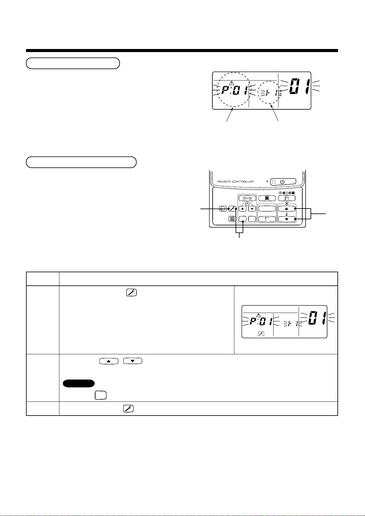
TROUBLESHOOTING
Confirmation and check
When a trouble occurred in the air conditioner, the
check code and the indoor unit No. appear on the
display part of the remote controller.
The check code is only displayed during the operation.
If the display disappears, operate the air conditioner
according to the following “Confirmation of error
history” for confirmation.
Confirmation of error history
When a trouble occurred on the air conditioner, the
error history can be confirmed with the following
procedure.
(The error history is stored in memory up to 4 errors.)
This history can be confirmed from either operating
status or stop status.
3
Check code
1
SET
UNIT No.
R.C. No.
Indoor unit No. in which
an error occurred
UNIT
CL
CODE No.
2
Procedure
1
2
3
Description
When pushing [SET] and buttons simultaneously for 4 seconds
or more, the right display appears.
If [Service Check] is displayed, the mode enters in the error history
mode.
• [01: Order of error history] is displayed in CODE No. window.
• [Check Code] is displayed in CHECK window.
• [Indoor unit address in which an error occurred] is displayed in
UNIT No.
Every pushing , buttons, the error history stored in the memory is displayed in order.
The numbers in CODE No. indicates CODE No. [01] (Latest) → [04] (Oldest).
CAUTION
Do not push
After confirmation, push button to return to the usual display.
button because all the error history of the indoor unit will be deleted.
CL
UNIT No.
R.C. No.
CODE No.
21
Page 25
Check method
On the remote controller (Main remote controller, Central control remote controller) and the interface P.C. board of
the outdoor unit (I/F), a check display LCD (Remote controller) or 7-segment display (on the outdoor interface P.C.
board) to display the operation is provided. Therefore the operation status can be known. Using this self-diagnosis
function, a trouble or position with error of the air conditioner can be found as shown in the table below.
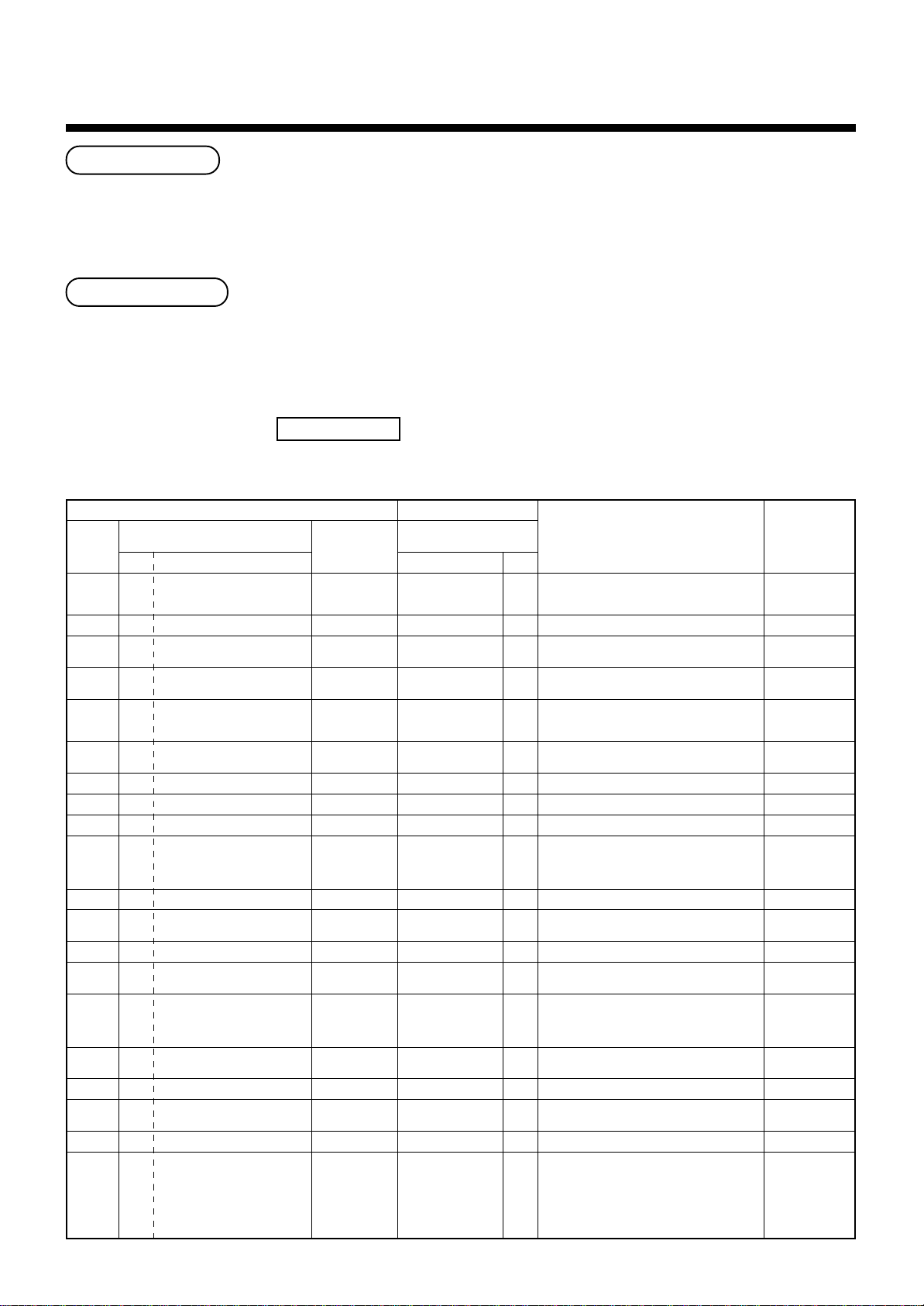
Check code list
The following list shows each check code. Find the check contents from the list according to part to be checked.
• In case of check from indoor remote controller: See “Main remote controller display” in the list.
• In case of check from outdoor unit: See “Outdoor 7-segment display” in the list.
• In case of check from AI-NET central control remote controller: See “AI-NET central control display” in the list.
• In case of check from indoor unit with wireless remote controller: See “Sensor block display of receiving unit” in the list.
AI-NET : Artificial Intelligence.
IPDU : Intelligent Power Drive Unit
¡ : Lighting,
ALT. : Flashing is alternately when there are two flashing LED.
: Flashing, l : Goes off
¤
SIM : Simultaneous flashing when there are two flashing LED.
Wireless remote controller
Sensor block display
of receiving unit
Operation
Timer Ready Flash
ll
¤
ll
¤
ll
¤
ll
ll
ll
ll
¤
ll
¤
ll
¤
ll
¤
ll
ll
ll
¤
ll
ll
ll
ll
ll
ll
ll
Communication error between indoor and
remote controller
(Detected at remote controller side)
Remote controller transmission error
Communication error between indoor and
remote controller (Detected at indoor side)
¤
¤
¤
¤
¤
¤
¤
¤
¤
¤
¤
¤
Communication circuit error between indoor/
outdoor (Detected at indoor side)
Decrease of No. of indoor units
Communication circuit error between indoor/
outdoor (Detected at outdoor side)
Duplicated indoor addresses
Duplicated main remote controllers
Communication error between indoor MCU
Automatic address start error
Indoor is nothing during automatic addressing
Capacity over / No. of connected indoor units
Communication error between indoor units
Outdoor header units quantity error
Other line connected during automatic
address
Sending error in communication between
outdoor units
Duplicated follower outdoor addresses
Decrease of No. of connected outdoor units
Follower outdoor unit error
IPDU communication error
Check code name
Judging device
Remote controller
Remote controller
Indoor
Indoor
I/F
I/F
Indoor / I/F
Remote controller
Indoor
I/F
I/F
I/F
Indoor
I/F
I/F
I/F
I/F
I/F
I/F
I/F
Main
remote
controller
display
E01
E02
E03
E04
E06
—
E08
E09
E10
E12
E15
E16
E18
E19
E20
E23
E25
E26
E28
E31
Terminology
Check code
Outdoor 7-segment display
Auxiliary code
——
——
——
——
No. of indoor units in which
E06
sensor has been normally
received
E07 —
E08 Duplicated indoor addresses
——
——
01: Indoor/Outdoor
E12
E15 —
E16
E19
E20
E23 —
E25 —
E26
E28 Detected outdoor unit number
E31 04:Fan IPDU error
communication
02: Communication between
outdoor units
00: Capacity over
~:No. of connected units
01
——
00: Header is nothing
02: Two or more header units
01: Outdoor of other line
connected
02: Indoor of other line
connected
No. of outdoor units which
received signal normally
01: IPDU1 error
02: IPDU2 error
03: IPDU1, 2 error
05: IPDU + Fan IPDU error
06: IPDU2 + Fan IPDU error
07: All IPDU error
AI-NET central
control display
—
—
97
04
04
—
96
99
CF
42
42
89
97, 99
96
42
15
15
15
d2
CF
22
Page 26
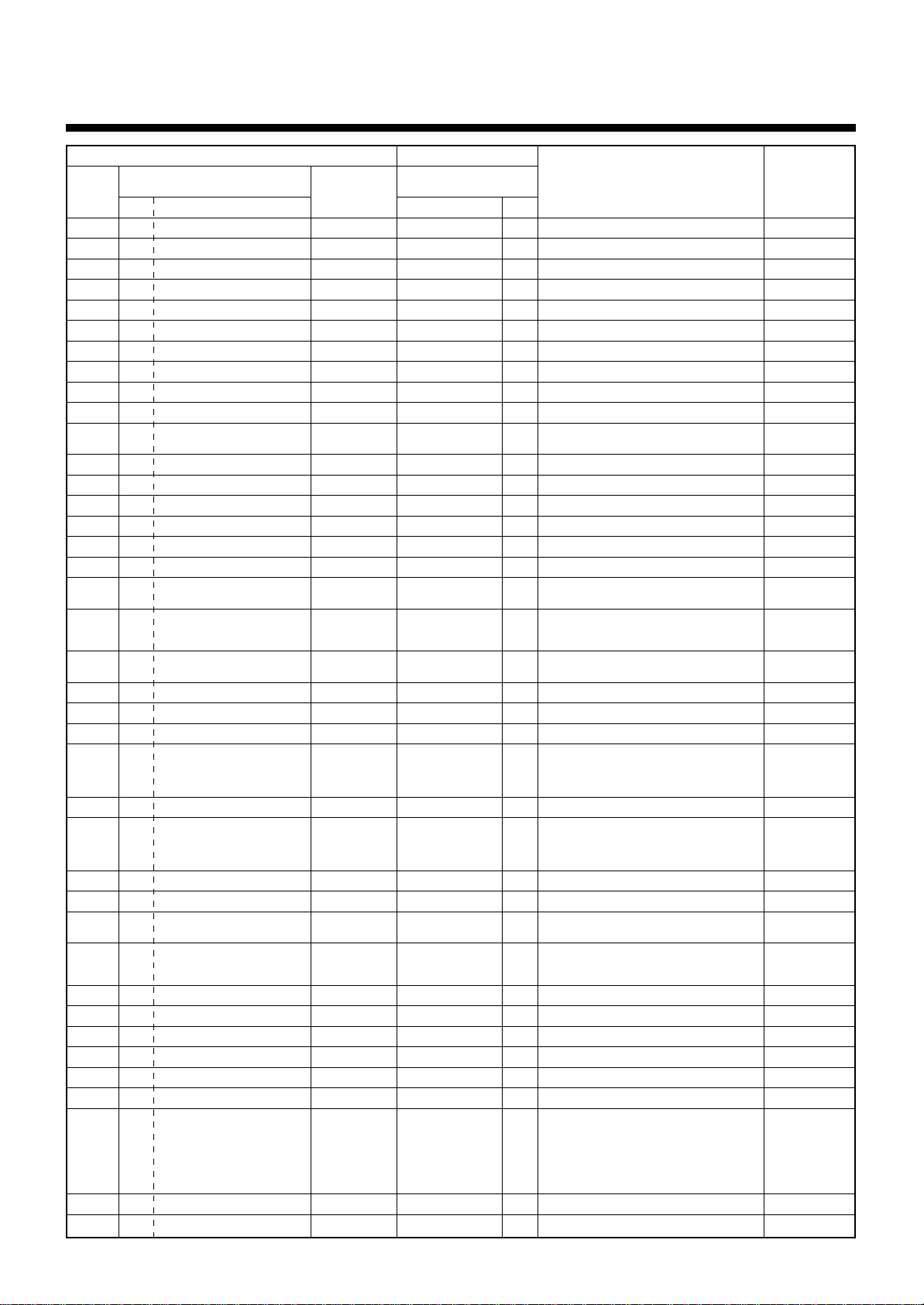
9
TROUBLESHOOTING
Main
remote
controller
display
F01
F02
F03
F04
F05
F06
F07
F08
F10
F12
F13
F15
F16
F23
F24
F29
F31
H01
H02
H03
H04
H06
H07
H08
H14
H16
L03
L04
L05
L06
L07
L08
L09
L10
L20
L28
L29
L30
—
Check code
Outdoor 7-segment display
Auxiliary code
——
——
——
F04 —
F05 —
F06 —
F07 —
F08 —
——
F12 —
01: Comp. 1 side
F13
02: Comp. 2 side
F15 —
F16 —
F23 —
F24 —
——
F31 —
01: Comp. 1 side
H01
02: Comp. 2 side
01: Comp. 1 side
H02
02: Comp. 2 side
01: Comp. 1 side
H03
02: Comp. 2 side
H04 —
H06 —
H07 —
01: TK1 sensor error
02: TK2 sensor error
H08
03: TK3 sensor error
04: TK4 sensor error
H14 —
01: TK1 oil circuit system error
02: TK2 oil circuit system error
H16
03: TK3 oil circuit system error
04: TK4 oil circuit system error
——
L04 —
——
L06 No. of indoor units with priority
——
L08 —
——
L10 —
L20 —
L28 —
01: IPDU1 error
02: IPDU2 error
03: IPDU3 error
L29 04: Fan IPDU error
05: IPDU1 + Fan IPDU error
06: IPDU2 + Fan IPDU error
07: All IPDU error
L30 Detected indoor address
L31 —
AI-NET central
control display
0F
0d
93
19
A1
18
18
1b
OC
A2
43
18
43
43
43
12
1C
IF
1d
17
44
20
d7
d4
44
d7
96
96
96
96
99
99
46
88
98
46
CF
b6
—
Wireless remote controller
Sensor block display
of receiving unit
Operation
Timer Ready Flash
ALT
l
¡
l
l
l
l
l
¡
¡
¡
¡
¡
l
ALT
l
ALT
l
ALT
¡
ALT
¡
ALT
¡
ALT
¡
ALT
¡
ALT
l
ALT
¡
ALT
¡
ALT
¡
ALT
¡
ALT
¡
ALT
¡
SIM
l
SIM
¡
l
¤
l
¤
l
¤
l
¤
l
¤
l
¤
l
¤
l
¤
l
¤
SIM
¤
SIM
¤
SIM
¤
SIM
¤
SIM
¤
SIM
¤
SIM
¤
SIM
¤
SIM
¤
SIM
¤
SIM
¤
SIM
¤
—
¤¤
¤¤
¤¤
¤¤
¤¤
¤¤
¤¤
¤¤
¤¤
¤¤
¤¤
¤¤
¤¤
¤¤
¤¤
¤¤
¤¤
l
l
l
l
l
l
l
l
l
¤
¤
¤
¤
¤
¤
¤
¤
¤
¤
¤
¤
Check code name
Indoor TCJ sensor error
Indoor TC2 sensor error
Indoor TC1 sensor error
TD1 sensor error
TD2 sensor error
TE1 sensor error
TL sensor error
TO sensor error
Indoor TA sensor error
TS1 sensor error
TH sensor error
Outdoor temp. sensor miscabling (TE, TL)
Outdoor pressure sensor miscabling (Pd, Ps)
Ps sensor error
Pd sensor error
Indoor other error
Indoor EEPROM error
Compressor break down
Magnet switch error
Overcurrent relay operation
Compressor trouble (lock)
Current detect circuit system error
Comp 1 case thermo operation
Low pressure protective operation
Oil level down detective protection
Oil level detective temp sensor error
Comp 2 case thermo operation
Oil level detective circuit error
Magnet switch error
Overcurrent relay operation
Indoor center unit duplicated
Outdoor line address duplicated
Duplicated indoor units with priority
(Displayed in indoor unit with priority)
Duplicated indoor units with priority
(Displayed in unit other than indoor unit with
priority)
Group line in individual indoor unit
Indoor group/Address unset
Indoor capacity unset
Outdoor capacity unset
Duplicated central control addresses
Over No. of connected outdoor units
No. of IPDU error
Indoor outside interlock
Extended I/C error
Judging device
Indoor
Indoor
Indoor
I/F
I/F
I/F
I/F
I/F
Indoor
I/F
IPDU
I/F
I/F
I/F
I/F
Indoor
I/F
IPDU
MG-SW
Overcurrent relay
IPDU
IPDU
I/F
I/F
I/F
I/F
I/F
I/F
MG-SW
Overcurrent relay
Indoor
I/F
I/F
I/F
Indoor
Indoor, I/F
Indoor
I/F
AI-NET, Indoor
I/F
I/F
Indoor
I/F
23
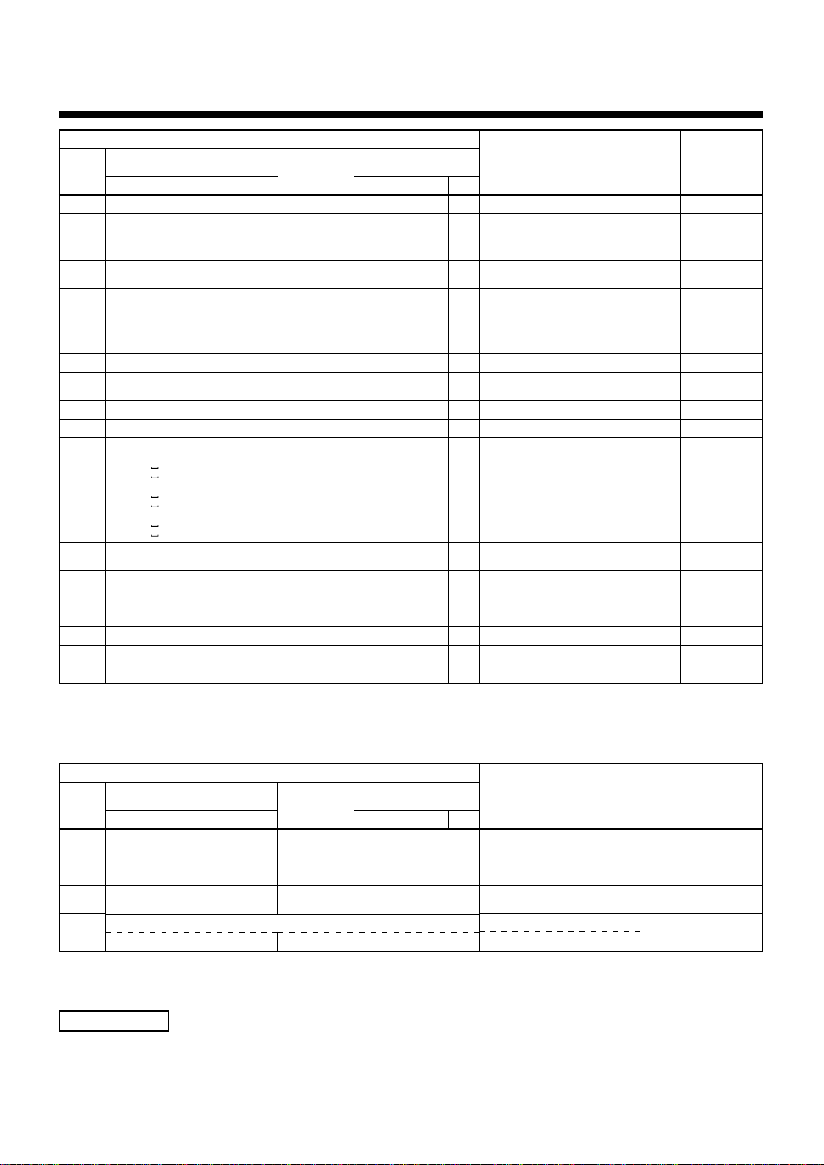
Page 27
Main
remote
controller
display
P01
P03
P04
P05
P07
P10
P12
P13
P15
P17
P19
P20
P22
P26
P29
P31
—
—
—
Check code
Outdoor 7-segment display
Auxiliary code
——
P03 —
01: Comp. 1 side
P04
02: Comp. 2 side
01: Phase-missing detection
P05
02: Phase error
01: Comp. 1 side
P07
02: Comp. 2 side
P10 Detected indoor address
——
P13 —
01: TS condition
P15
02: TD condition
P17 —
P19 Detected outdoor unit number
P20 —
0 : IGBT short
: Fan motor position
1
detective circuit error
3
P22
P26
P29
P31 —
: Fan motor trouble
: TH sensor temp. error
C
(Heat sink overheat)
D
: TH sensor error
: Vdc output error
E
01: Comp. 1 side
02: Comp. 2 side
01: Comp. 1 side
02: Comp. 2 side
——
——
——
AI-NET central
control display
11
1E
21
AF
IC
Ob
11
47
AE
bb
O8
22
1A
14
16
47
b7
97
99
Wireless remote controller
Sensor block display
of receiving unit
Operation
Timer Ready Flash
l
¤¤
l
¤
l
¤
l
¤
l
¤
l
¤¤
l
¤¤
l
¤¤
l
¤
l
¤
l
¤
l
¤
l
¤
l
¤
l
¤
l
¤
By alarm device ALT
—
—
ALT
ALT
¤
ALT
¤
ALT
¤
ALT
¤
ALT
ALT
ALT
ALT
¤
ALT
¤
ALT
¤
ALT
¤
ALT
¤
ALT
¤
ALT
¤
ALT
¤
Check code name
Indoor fan motor error
Discharge temp. TD1 error
High-pressure SW system operation
Phase-missing detection /Phase error
Heat sink overheat error
Indoor overflow error
Indoor fan motor error
Outdoor liquid back detection error
Gas leak detection
Discharge temp. TD2 error
4-way valve inverse error
High-pressure protective operation
Outdoor fan IPDU error
G-TR short protection error
Comp position detective circuit system error
Other indoor unit error
(Group terminal unit error)
Error in indoor group
AI-NET communication system error
Duplicated network adaptors
Judging device
Indoor
I/F
IPDU
I/F
IPDU, I/F
Indoor
Indoor
I/F
I/F
I/F
I/F
I/F
IPDU
IPDU
IPDU
Indoor
AI-NET
AI-NET
AI-NET
Error detected by TCC-LINK central control device
Central
control
device
indication
C05
C06
C12
P30
Check code
Outdoor 7-segment display
Auxiliary code
——
——
——
Differs according to error contents of unit with occurrence of alarm
——
AI-NET central
control display
—
—
—
Wireless remote controller
Sensor block display
of receiving unit
Operation
Timer Ready Flash
(L20 is displayed.)
Terminology
TCC-LINK : TOSHIBA Carriea Cominication Link.
24
Check code name
—
—
—
Sending error in TCC-LINK central
control device
Receiving error in TCC-LINK central
control device
Batch alarm of general-purpose
equipment control interface
Group control branching unit error
Duplicated central control addresses
Judging device
TCC-LINK
TCC-LINK
General-purpose equipment
I/F
TCC-LINK
Page 28
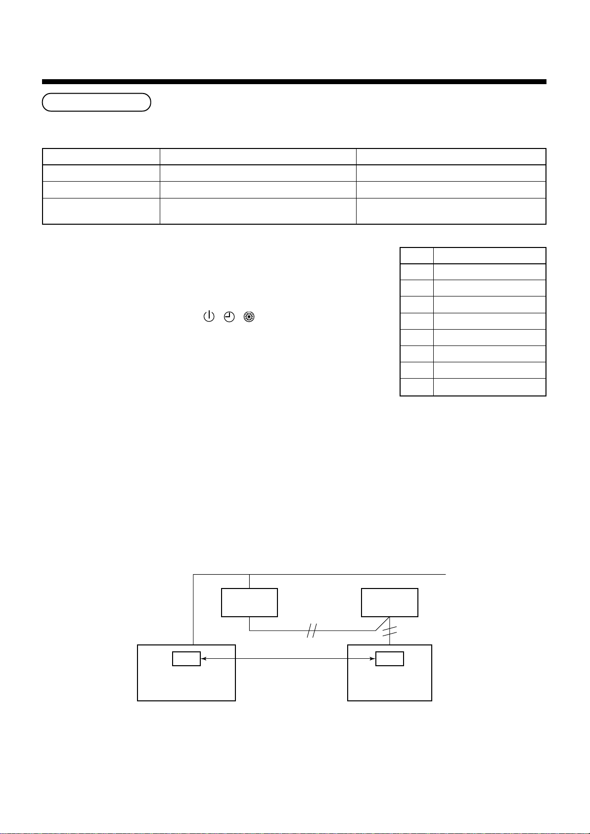
9
TROUBLESHOOTING
New check code
1. Difference between the new check code and the current system
The displaying method of the check code changes in this model and after.
Used characters
Characteristics of code classification
Block display
Check code in current system
Hexadecimal notation, 2 digits
Few classification of communication/incorrect setup system
Indoor P.C. board, Outdoor P.C. board, Cycle, Communication
Alphabet + Decimal notation, 2 digits
Many classification of communication/incorrect setup system
Communication/Incorrect setup (4 ways), Indoor protection,
Outdoor protection, Sensor, Compressor protection, etc.
New check code
<Display on wired remote controller>
• [CHECK] goes on.
• [UNIT No.] + Check code + Operation lamp (Green) flash
<Display on sensor part of wireless>
• Block display of combination of [ ] [ ] [ ]
<Display on indicater on wiress remote controller
receiver part>
• Unit No. and check code are displayed.
→
Display
A
C
E
F
H
J
L
Classification
Unused
Central control system error
Communication system error
Each sensor error (Failure)
Compressor protective system error
Unused
Setup error, Other errors
• In a case of error with auxiliary code, check code and
P
auxiliary code are displayed alternately.
Protective device operation
2. Special mention
1) If this model is connected to AI-NET by network adaptor, the different check codes are displayed on the main
remote controller (New check code display on new remote controller) and AI-NET central control remote
controller (Current system check code display on the current system central control remote controller).
2) The check code is displayed only while the air conditioner is operating (Remote controller start button ON).
When the air conditioner stops and the error is cleared, the check code display on the remote controller also
disappears. However, if the error continues after stop of the operation, the check code is immediately
displayed with restarting.
OC
AI-NET central control
remote controller
Network
adaptor
AI-NET WORK bus
Indoor unit
F10
Main
remote controller
25
Page 29
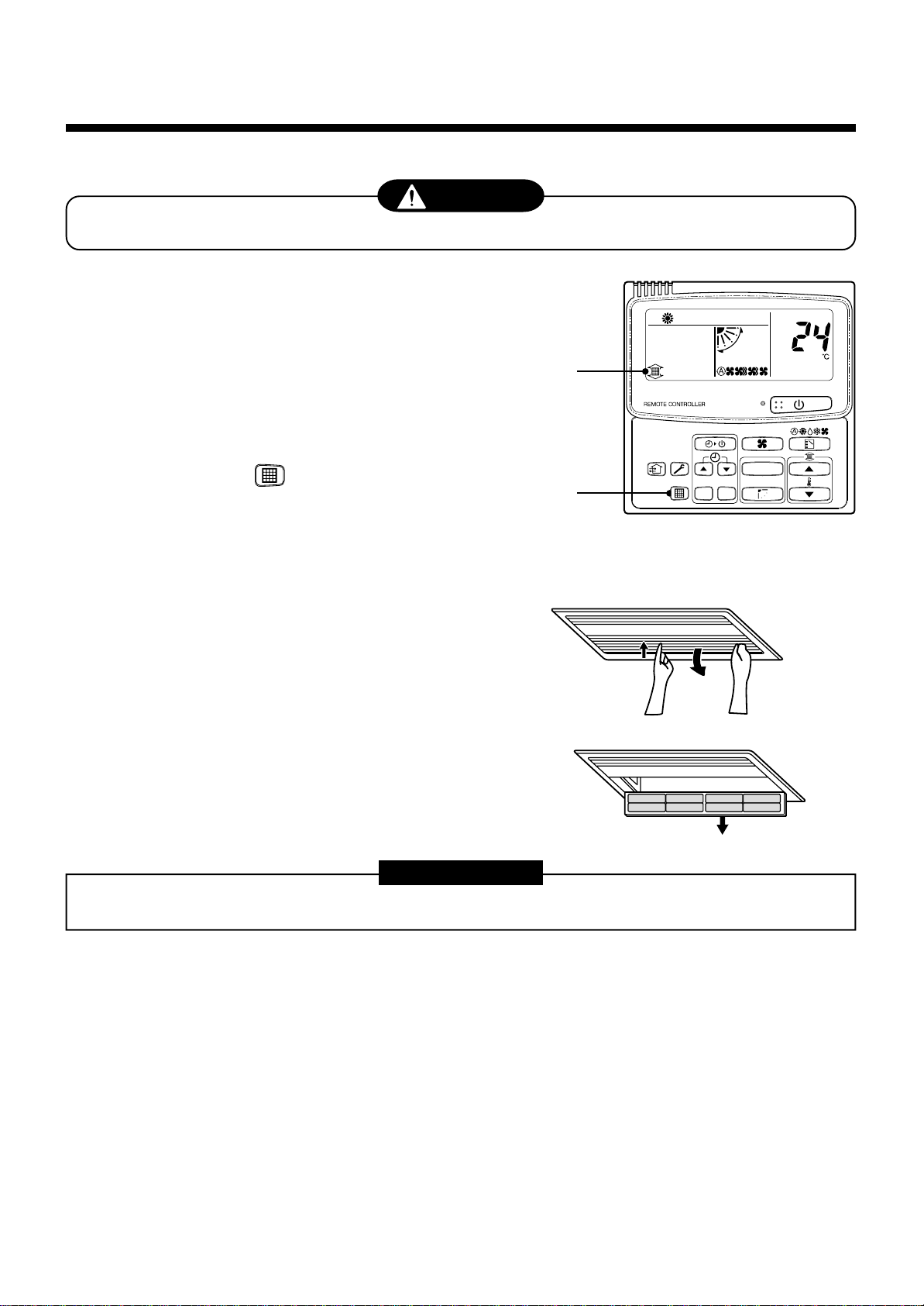
1,
2
3
UNIT
CODE No.
SET
CL
10
For maintenance, be sure to turn off the main power switch.
Do not handle the buttons with wet hands; otherwise an electric shock may be caused.
<Daily maintenance>
Cleaning of air filter
1
If [FILTER] is displayed on the remote controller,
maintain the air filter.
2
Clogging of the air filter decreases cooling/
heating efficiency.
3
After cleaning, push .
[FILTER] display disappears.
MAINTENANCE
CAUTION
[1-way Air Discharge Cassette Compact Type]
1
Push [PUSH] at the center and left/right of the air
inlet port to open the air inlet port.
2
Take out the air filter by lifting up it once and then
pull it downward.
REQUIREMENT
• Insert the air filter of 1-way Air Discharge Cassette Compact Type surely into the specified position.
26
Page 30
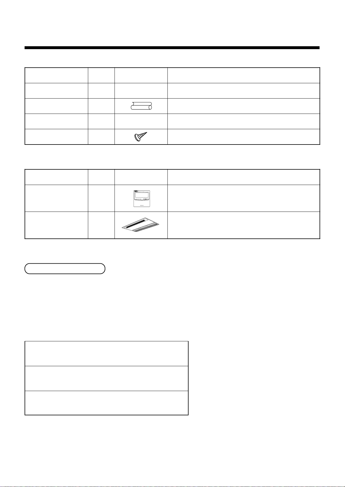
Pièces accessoires et pièces non fournies
H Pièces accessoires
Nom de la pièce Quantité Forme Utilisation
Manuel d’installat ion 1 Ce manuel (Veillez à le remettre aux utilisateurs)
Tube d’isolation thermique 2 Pour l’isolation thermique des sections de raccordement des tuyaux
Gabarit d’installation 1 — Pour vérifier l’ouverture du plafond et la position de l’unité principale
Vis de fixation du gabarit 5 Fixation du gabarit d’installation
<Pièces vendues séparément>
Nom de la pièce Quantité Forme Utilisation
Télécommande avec fil
standard
Panneau pour plafond 1 Modèle :
1 Modèle :
RBC-AMT21E
RBC-UY135PG
Tuyaux de réfrigérant
• Le kit de tuyaux utilisé pour le réfrigérant traditionnel ne peut pas être utilisé.
• Utilisez un tuyau en cuivre de 0,8 mm ou plus d’épaisseur pour Ø 6.4, Ø 9.5, Ø 12.7.
• Les écrous évasés et l’évasement diffèrent également de ceux des tuyaux du réfrigérant traditionnel.
Retirez l’écrou évasé fourni avec l’unité principale du climatiseur et utilisez-le.
H Pièces non fournies
Tuyau de raccordement (côté liquide)
(6.4 mm (diam.), (diam.) épaisseur nominale 1/4 pouces (0.8 mm)
Tuyau de raccordement (côté gaz)
(12.7 mm (diam.), (diam.) épaisseur nominale 3/8 pouces (0.8 mm)
Cordon d’alimentation
Câble 3-fils 2.5 mm
2
, conformément au Plan 60245 IEC57
27
Page 31

1
• Assurez-vous de respecter toutes les règles locales, nationales et internationales.
• Lisez attentivement ces “MESURES DE SÉCURITÉ” avant l’installation.
• Les mesures décrites ci-après comprennent des points importants concernant la sécurité.
Observez-les scrupuleusement.
• Après l’installation, faites un essai de fonctionnement pour vous assurer de l’absence de problèmes.
Reportez-vous au Manuel du propriétaire pour expliquer au client comment utiliser l’unité et effectuer son entretien.
• Mettez l’interrupteur général (ou le disjoncteur) hors tension avant d’effectuer l’entretien de l’unité.
• Demandez au client de conserver le Manuel d’installation avec le Manuel du propriétaire.
MESURES DE SECURITE
ATTENTION Installation d’un climatiseur utilisant le nouveau réfrigérant
• Ce climatiseur utilise le nouveau réfrigérant HFC (R410A) qui ne détruit pas la couche d’ozone.
Les caractéristiques du réfrigérant R410A sont les suivantes : absorption aisée de l’eau, membrane oxydante ou
huile et sa pression, d’environ 1.6 fois plus élevée que celle du réfrigérant R22. L’huile réfrigérante a elle aussi
été changée.
Par conséquent, durant l’installation, assurez-vous que l’eau, la poussière, le réfrigérant précédent ou l’huile
réfrigérante n’entrent pas dans le circuit de réfrigération.
Pour éviter de remplir avec du réfrigérant et de l’huile réfrigérante inappropriés, la taille des sections de
raccordement de l’orifice de remplissage de l’unité principale et les outils d’installation sont différents de ceux
qui sont utilisés pour le réfrigérant traditionnel.
En conséquence, les outils exclusifs sont requis pour le nouveau réfrigérant (R410A).
Quant aux tuyaux de raccordement, utilisez des tuyaux neufs et propres conçus pour le R410A et veillez à ce
que l’eau ou la poussière n’y entrent pas.
En outre, n’utilisez pas la tuyauterie existante, qui pose des problèmes de résistance à la pression et
d’impureté.
FRANCAIS
ATTENTION Pour déconnecter l’appareil du secteur.
Cet appareil doit être connecté au secteur via un interrupteur ayant une séparation de contact d’au moins 3 mm.
AVERTISSEMENT
• Demandez à un revendeur autorisé ou à un installateur professionnel d’installer le climatiseur /
d’effectuer son entretien.
Une installation inadéquate peut se solder par une fuite d’eau, une électrocution ou un incendie.
• Mettez l’interrupteur général ou le disjoncteur hors tension avant d’entreprendre l’installation
électrique.
Assurez-vous que tous les interrupteurs soient hors tension. La non-observation de cet avertissement peut se
solder par une électrocution.
• Branchez correctement le câble de raccordement.
Si le câble de raccordement est mal branché, les composants électriques peuvent s’endommager.
• Lorsque vous déplacez le climatiseur pour l’installer ailleurs, faites très attention à ce qu’aucun
corps gazeux autre que le réfrigérant spécifié n’entre dans le circuit de réfrigération.
Si l’air ou tout autre gaz se mélange au réfrigérant, la pression gazeuse du circuit de réfrigération augmente
de façon anormale et risque de faire éclater les tuyaux et blesser quelqu’un.
• Ne modifiez pas cette unité en démontant ses carters de protection ou en by-passant ses
verrous de sûreté.
• Exposer l’unité à l’eau ou à l’humidité avant l’installation peut provoquer un court-circuit.
Ne la rangez pas dans un sous-sol humide et ne l’exposez pas à la pluie ou à l’eau.
28
Page 32

1
MESURES DE SECURITE
• Après avoir déballé l’unité, examinez-la attentivement pour vous assurer qu’elle n’est pas
endommagée.
• Ne l’installez pas dans un endroit susceptible d’augmenter ses vibrations.
• Afin d’éviter de vous blesser (avec des bords tranchants), faites attention lorsque vous
manipulez les pièces.
• Effectuez l’installation conformément au Manuel d’installation.
Une installation inadéquate peut se solder par une fuite d’eau, une électrocution ou un incendie.
• Si le climatiseur est installé dans une petite pièce, prenez les mesures appropriées pour
garantir que la concentration de fuite de réfrigérant dans la pièce ne dépasse pas le niveau
critique.
• Installez solidement le climatiseur dans un endroit qui supporte son poids de manière adéquate.
• Effectuez l’installation spécifiée pour protéger le climatiseur contre un tremblement de terre.
Si le climatiseur n’est pas installé de manière appropriée, il peut tomber et provoquer des accidents.
• Si le gaz réfrigérant a fui durant l’installation, aérez immédiatement la pièce.
Si le gaz réfrigérant qui a fui entre en contact avec le feu, un gaz nocif peut se dégager.
• Après l’installation, assurez-vous que le gaz réfrigérant ne fuit pas.
Si le gaz réfrigérant fuit dans la pièce et s’écoule près d’une source de chaleur, comme une cuisinière, un gaz
nocif peut se dégager.
• L’installation électrique doit être effectuée par un électricien professionnel conformément au
Manuel d’installation. Assurez-vous que le climatiseur utilise une alimentation qui lui est
réservé.
Une alimentation électrique insuffisante ou une installation inappropriée peuvent provoquer un incendie.
• Utilisez les câbles indiqués et raccordez-les bien aux bornes. Evitez qu’une pression externe ne
s’exerce sur les bornes et ne les affecte.
• Observez les règles du fournisseur d’électricité local lorsque vous raccordez les câbles
d’alimentation.
Une mise à la terre inappropriée peut provoquer une électrocution.
• N’installez pas le climatiseur dans un endroit susceptible d’être exposé à des gaz inflammables.
Si un gaz inflammable fuit et stagne autour de l’unité, il peut provoquer un incendie.
29
Page 33

2
SELECTION DU LIEU D’INSTALLATION
AVERTISSEMENT
• Installez le climatiseur dans un endroit suffisamment robuste pour supporter son poids.
Si l’endroit n’est pas assez robuste, l’unité peut tomber et provoquer des blessures.
• Effectuez l’installation spécifiée pour protéger le climatiseur contre un tremblement de terre.
Une unité mal installée peut tomber et provoquer des accidents.
• Installez le climatiseur à un minimum de 2.5 m de hauteur du sol.
Il est dangereux d’introduire vos mains ou d’autres objets dans le climatiseur pendant son fonctionnement car
vous pourriez toucher le ventilateur en rotation ou des parties sous-tension.
ATTENTION
• N’installez pas le climatiseur dans un endroit susceptible d’être exposé à un gaz inflammable.
Si le gaz inflammable fuyait et s’accumulait près de l’unité, un incendie pourrait avoir lieu.
Si le client l’autorise, installez le climatiseur dans un endroit remplissant les conditions suivantes.
• Un endroit où l’unité puisse être installée à l’horizontale.
• Un endroit ayant assez d’espace pour effectuer son entretien et son inspection en toute sécurité.
• Un endroit où l’eau évacuée ne posera aucun problème.
Evitez d’installer le climatiseur dans les endroits suivants.
• Un endroit où l’air est riche en sel (zone de bord de mer) ou en gaz sulfureux (source chaude).
(Si l’unité doit être utilisée dans ces endroits, des mesures de protection particulières s’avèrent nécessaires.)
• Un endroit exposé à l’huile, à la vapeur, aux fumées d’huile ou aux gaz corrosifs.
• Un endroit à proximité duquel un solvant organique est utilisé.
• Un endroit proche d’une machine génératrice de hautes fréquences.
• Un endroit où l’air refoulé souffle directement sur la fenêtre de la maison voisine. (Pour l’unité extérieure)
• Un endroit où le bruit de l’unité extérieure se transmet facilement. (Lorsque vous installez le climatiseur dans
un endroit confinant avec votre voisinage, prêtez attention au niveau sonore.)
• Un endroit peu ventilé.
Espace requis pour l’installation
Prévoyez l’espace nécessaire pour installer l’unité à l’extérieur et pour en assurer l’entretien.
Hauteur intérieure du plafond :
Orifice pour le tuyau de réfrigérant
245mm ou davantage
100 mm et
davantage
Vous pouvez modifier la configuration de la minuterie d’alarme du filtre (Indiquant de nettoyer le filtre) sur la
télécommande en fonction de l’installation. Si la pièce n’est pas suffisamment chauffée à cause de l’endroit de
l’installation ou de la configuration de la pièce, vous pouvez augmenter le seuil de température.
Pour savoir comment procéder, consultez les paragraphes “Modification de la configuration de la minuterie du filtre”
et “Comment améliorer le chauffage” de ce Manuel.
100 mm et
davantage
Plafond
200 mm ou
davantage
30
Page 34

2
SELECTION DU LIEU D’INSTALLATION
Enlèvement des caoutchoucs de transport
• Avant d’installer l’unité intérieure, enlevez les deux
caoutchoucs de protection pendant le transport qui sont
placés entre les étriers de renfort du moteur du
ventilateur et du carter.
(Remettez les caoutchoucs de transport aux clients en
leur demandant de les conserver pour les utiliser en cas
de nouveau transport ou de réinstallation)
Caoutchoucs de protection pendant
le transport (enlever)
Tirez vers le haut
et enlevez.
Etrier de renfort
Carter
Sur les types sans-fil
Le capteur de l’unité extérieure à télécommande
sans-fil peut recevoir le signal jusqu’à environ 8
mètres. Choisissez en fonction de cette donnée où
placer la télécommande et l’unité intérieure.
• Pour éviter les dysfonctionnement, choisissez un
endroit à l’abri de la lumière solaire directe et des
lumières fluorescentes.
• Vous pouvez installer dans la même pièce deux
unités intérieures ou davantage (6 au maximum) à
télécommande.
8 m ou moins
3
INSTALLATION DE L’UNITE INTERIEURE
AVERTISSEMENT
Installez solidement le climatiseur dans un endroit suffisamment résistant pour supporter son poids.
Si l’endroit n’est pas assez résistant, l’unité peut tomber et provoquer des blessures.
Effectuez l’installation spécifiée pour protéger le climatiseur contre les vents forts et les tremblements de terre.
Une unité mal installée peut tomber et provoquer des accidents.
CONDITIONS REQUISES
Observez scrupuleusement les règles suivantes pour éviter d’endommager les unités intérieures et de vous
blesser.
• Ne posez aucun objet lourd sur l’unité intérieure. (Les unités sont emballées à plat.)
• Si possible, transportez l’unité intérieure telle qu’elle est emballée. Si vous êtes obligé de transporter l’unité
intérieure déballée, assurez-vous d’utiliser des chiffons, etc. pour ne pas l’endommager.
• Pour déplacer l’unité intérieure, tenez seulement les crochets métalliques (4 points).
N’exercez aucune force sur les autres pièces (tuyau de réfrigérant, bac d’évacuation, pièces expansées ou
pièces en résine, etc.).
• Portez l’emballage à deux personnes ou plus et ne l’empaquetez pas avec du ruban adhésif sur des points
autres que ceux qui sont spécifiés.
• Le pas du boulon de suspension dans le sens longitudinal n’est pas centré sur la taille de l’ouverture du plafond.
Par conséquent, vérifiez la position relationnelle sur la vue Extérieure.
Si la position relationnelle est incorrecte, le regard ne pourra pas être installé.
31
Page 35

Vue extérieure
Borne de connexion électrique
Bouche de raccordement du
tuyau d’évacuation (VP25)
150
225
100
Dimension extérieure du panneau 1050
Dimension de l’ouverture au plafond 1010
890
455395
110
Panneau central 850
850
2020
330
400
50
Boulon de suspension
4-M10 Placé sur place
43020 20
470
au plafond
du panneau
Dimension extérieure
Dimension de l’ouverture
400
200
Orifice de raccordement des tuyaux
de réfrigérant (côté gaz Ø9,5)
Orifice de raccordement des tuyaux
de réfrigérant (côté liquide Ø6,4)
5 positions du trou de
montage du panneau
• Télécommande avec fil
(RBC-AMT21E)
4
Métal de
23518
120
85
Panneau pour plafond
(vendu séparément)
Volet de refoulement
470
Orifice d’évacuation
1050
Grille d’aspiration d’air
140
Surface inférieure
du plafond
support
Espace nécessaire pour l’installation et le dépannage
2.7
ou
245mm
davantage
120
120
16
100mm
ou davantage
32
100mm
ou davantage
200mm
ou davantage
Page 36

3
INSTALLATION DE L’UNITE INTERIEURE
Ouverture du plafond et installation des boulons de suspension
• En tenant compte du raccordement des tuyaux/câbles à l’intérieur du plafond après avoir suspendu l’unité
intérieure, choisissez un lieu d’installation et déterminez l’orientation des tuyaux.
• Après avoir choisi le lieu d’installation de l’unité intérieure, pratiquez l’ouverture au plafond et montez les boulons
de suspension.
• Pour connaître la dimension de l’ouverture au plafond et le pas du boulon de suspension, consultez la vue de
l’extérieur et le gabarit de montage joint.
• Si le plafond est déjà préparé, tirez le tuyau d’évacuation, le tuyau de réfrigérant, le câble de liaison unité
intérieure/extérieure, le câble du système de commande central et le câble de la télécommande jusqu’à leur
position de connexion avant de suspendre l’unité intérieure.
Procurez-vous sur place les boulons et
les écrous de suspension nécessaires
pour installer l’unité intérieure.
Boulon de suspension
Ecrou
Rondelle plate
M10 ou W3/8
M10 ou W3/8
M10
4 pièces
12 pièces
8 pièces
[Comment utiliser le gabarit de montage joint]
Le gabarit de montage est fixé au couvercle de l’emballage.
<Avec un plafond existant>
Utilisez le gabarit pour positionner l’ouverture au plafond et le
boulon de suspension.
<Avec un nouveau plafond>
Utilisez le gabarit pour positionner l’ouverture au plafond lorsque
vous aménagez un nouveau plafond.
• Installez l’unité intérieure après avoir monté les boulons de
suspension.
• Utilisez les vis de fixation du gabarit fournies (M5 × 20L : 4 ),
fixez le gabarit d’installation sur l’unité intérieure.
(Vissez les supports de montage du panneau de plafond)
• Lorsque vous aménagez le plafond, pratiquez un trou sur le
côté externe du gabarit d’installation.
Vis de fixation du panneau du plafond
(utilisez les vis fournies)
Feuille gabarit
Installation du boulon de suspension
Utilisez des boulons de suspension M10 (4, non fournis).
En les faisant correspondre à la structure existante, réglez leur pas en fonction de la taille indiquée sur la vue
extérieure de l’unité ci-dessous.
Nouveau bloc de béton
Installez les boulons avec des brides
d’insertion ou des boulons d’ancrage.
(Support
à lame)
(Support
à coulisse)
(Boulon d’ancrage de
suspension des tuyaux)
Boulon d’ancrage
Acier
renforcé
Utilisez les angles existants ou installez
de nouveaux angles de support.
Structure en acier
Boulon de suspension
Boulon de suspension Angle de support
Bloc en béton existant
Utilisez des chevilles, des fiches
ou des boulons perforés.
Installation de la télécommande (vendue séparément
Pour l’installation de la télécommande avec fil, suivez le Manuel d’installation fourni avec la télécommande.
Pour l’installation de la télécommande sans-fil, suivez le Manuel d’installation fourni avec la télécommande.
• Ne placez pas la télécommande dans un endroit exposé à la lumière directe du soleil, près d’un poêle, etc.
• Actionnez la télécommande, contrôlez si l’unité intérieure reçoit correctement le signal puis installez la
télécommande. (Type sans-fil)
• Installez la télécommande à 1 mètre des dispositifs comme les postes de télé ou les chaînes stéréo. (Risque de
recevoir des images brouillées ou des bruits parasites) (Type sans-fil)
33
Page 37

Installation de l’unité intérieure
Boulon de suspension
Rondelle (en haut)
(Support de
suspension de
l’unité principale)
Rondelle (du bas)
Ecrous (du bas)
Ecrou (côté supérieur)
137mm
Surface inférieure du plafond
Ouverture
(Dimension de l’ouverture du plafond)
(Dimension de
l’ouverture du
plafond)
P0151, P0181 : 1160
P0241 : 1360
50110
695
2020
Encombrement de
l’unité intérieure
ATTENTION
L’unité intérieure est équipée d’une pompe d’évacuation
incorporée et d’un flotteur. N’inclinez jamais l’unité principale.
Boulon de suspension
(W3/8 ou M10)
Ecrou
(W3/8 ou M10)
Ecrou
(W3/8 ou M10)
Sinon le flotteur risque de mal fonctionner et de provoquer des
fuites d’eau.
• Fixez l’écrou (M10 ou W3/8 : acheté sur place) et la rondelle jointe
(Ø 34 mm) au boulon d’ancrage.
(1)Nécessaires sur place rondelles plates
supérieures à M10
(2)Pour éviter que le boulon ne tombe (sécurité),
assurez-vous de le placer juste en dessous du
support de suspension comme le montre la figure.
• Réglez la position de l’écrou (partie inférieure) de sorte que l’écart la
partie inférieure et la partie inférieure du panneau soit de 137 mm.
• Suspendez l’unité principale en accrochant l’écrou du boulon de
suspension à la rainure en T du support de suspension de l’unité
principale.
• A l’aide d’un niveau, etc. , réglez le niveau horizontal de l’unité
intérieure.
• A l’aide du gabarit d’installation, vérifiez et réglez la position entre
l’unité intérieure et l’ouverture du plafond ainsi que la hauteur de
suspension de l’unité intérieure.
• Les vis utilisées pour fixer le gabarit d’installation servent encore pour monter le panneau.
• Avec les vis de fixation du panneau du plafond, fixez le gabarit d’installation
en dessous de l’unité intérieure.
• Ajustez la dimension de l’ouverture du plafond au gabarit d’installation.
(1)
Rondelle plate
M10 (accessoire)
(2)
Rondelle plate
M10 (accessoire)
• Placez au même niveau la surface du plafond et le bas du gabarit d’installation.
• Fixez solidement l’unité intérieure en serrant l’écrou du
Gabarit d’installation
partie inférieure du
gabarit d’installation
Unité intérieure
partie inférieure du
gabarit d’installation
Mettez au même niveau.
Surface inférieure
du plafond
Surface inférieure
du plafond
haut.
Niveau
Fixez solidement
CONDITIONS REQUISES
• A l’aide d’un niveau, etc. , réglez le niveau
horizontal de l’unité intérieure.
• Serrez l’écrou solidement et fixez l’unité.
Unité intérieure
Saillant : 0 mm ou davantage
Installation du panneau pour plafond
(vendu séparément)
Installez le panneau pour plafond conformément au
Manuel d’installation après avoir terminé les travaux de
tuyauterie/câblage.
Vérifiez que l’installation de l’unité intérieure et
l’ouverture du plafond soient correctes, puis installez-la.
Raccordez étroitement les raccords entre le
panneau de plafond et la surface du plafond et entre
le panneau de plafond et l’unité intérieure.
S’il y a du jeu, des fuites d’air s produisent et
provoquent la formation de condensats ou de fuites
d’eau.
Unité intérieure
Dessin : 3 mm ou moins
CONDITIONS REQUISES
34
Page 38

4
INSTALLATION DES TUYAUX D’EVACUATION
ATTENTION
• Conformément au Manuel d’installation,
raccordez les tuyaux d’évacuation de façon à ce
que l’eau s’écoule correctement et appliquez un
isolant thermique de façon à éviter la formation
Tuyauterie/Isolant et dimension
Les matériaux suivants servant aux travaux de
plomberie et d’isolation sont achetés sur place.
Tuyauterie
Manchon en chlorure de vinyle dur VP25
(diam. extérieur : Ø 32 mm)
de condensats.
Les pannes de raccordement des tuyaux risquent
de provoquer des fuites d’eau dans la pièce et de
Isolant
Mousse de polyéthylène , épaisseur :
10 mm ou davantage
mouiller le mobilier.
CONDITIONS REQUISES
• Assurez-vous d’effectuer le calorifugeage des tuyaux d’évacuation de l’unité intérieure.
• N’oubliez pas d’effectuer le calorifugeage de la section de raccordement avec
l’unité intérieure. Toute isolation thermique incomplète provoque des condensats.
• Inclinez le tuyau d’évacuation vers le bas (1/100 ou davantage) et ne créez ni
hernie ni siphon sur les tuyaux. Cela risquerait de provoquer un bruit anormal.
• Limitez la longueur du tuyau d’évacuation transversal à 20 m ou moins.
Si le tuyau long est long, placez des supports tous les 1.5/2 m pour éviter
qu’il n’ondule.
• Posez les tuyaux collectifs de la façon
Le plus long possible (10cm)
VP25
VP25
illustrée sur la figure de droite.
• Ne montez pas de tuyau de purge
(Tuyaux collectifs)
d’air car en giclant l’eau de drainage
provoquerait des condensats.
VP30 ou davantage
Pente descendante
de 1/100 ou davantage
Isolant
thermique
VP25
De 1.5m à 2m
1/100 ou
davantage vers le bas
Forme
arquée
Siphon
Support
Raccordement du tuyau d’évacuation
Raccordez le tuyau en chlorure de vinyle dur sur la bouche du tuyau d’évacuation.
• A l’aide d’un adhésif pour tuyau en chlorure de vinyle, raccordez bien les tuyaux en chlorure de vinyle dur de sorte
qu’ils ne fuient pas.
• Appliquez de façon homogène un adhésif sur 40 mm à l’extrémité du tuyau en chlorure de vinyle et introduisez-le
à fond sur la prise d’évacuation.
CONDITIONS REQUISES
• A l’aide d’un adhésif pour tuyau en chlorure de vinyle, raccordez bien les tuyaux en chlorure de vinyle dur de
sorte qu’ils ne fuient pas.
• L’adhésif sèche et durcit très lentement.
(Consultez le Mode d’emploi de l’adhésif). Evitez de forcer sur la section de raccordement sur les tuyaux
d’évacuation.
Evacuation ascendante
Si une pente descendante du tuyau d’évacuation ne peut
être assurée, il est possible de réaliser une évacuation
ascendante.
• Réglez la hauteur du tuyau d’évacuation à 350 mm du
bas du plafond.
• Sortez le tuyau d’évacuation sur 150 mm par l’extrémité
de l’orifice de raccordement du tuyau d’évacuation de
l’unité intérieure et faites-le monter à la verticale.
• Après avoir fait monter le tuyau d’évacuation, mettez-le à
l’horizontale et pliez-le immédiatement vers le bas.
100 m
ou moins
Unité intérieure
Elévation jusqu’à
150 mm ou moins
Elévation jusqu’à
Dessous du plafond
350 mm ou moins
35
Page 39

Vérification de l’évacuation
Monophasée 220-240 V, 50 Hz
220 V, 60 Hz
R(L) S(N)
Noir Blanc
Noir
Noir
NoirBlanc
Tirez
Flotteur
Connecteur de circuit imprimé CN030 (rouge)
Après les travaux de plomberie, vérifiez si l’eau
s’écoule normalement et si les raccords des tuyaux ne
fuient pas. Vérifiez aussi s’il n’y a pas de bruit anormal
au niveau du moteur de la pompe d’évacuation.
Assurez-vous de vérifier l’évacuation si vous effectuez
l’installation pendant la période de chauffage.
Lorsque l’installation électrique est terminée :
• Avant de monter un panneau, versez de l’eau, de la façon illustrée sur la figure suivante, et vérifiez si l’eau est
évacuée à travers l’orifice du tuyau d’évacuation (transparent) pendant le fonctionnement en mode FROID, puis
vérifiez s’il n’y a pas de fuites d’eau au niveau des tuyaux d’évacuation.
Lorsque l’installation électrique n’est pas terminée :
• Sortez le raccord du flotteur (2P : Blanc). (Vérifiez aussi si le courant est coupé)
• Branchez le courant monophasé 220-240 V 50 Hz (ou 220 V 60 Hz) sur les bornes R (L) et S (N). (Ne branchez
jamais le 220-240 V sur (A), (B), (U1) et (U2) car la carte à circuits imprimés tomberait en panne).
• Sous-tension, le moteur de la pompe d’évacuation fonctionne automatiquement. Vérifiez si l’eau est évacuée à
travers l’orifice du tuyau d’évacuation (transparent) , puis vérifiez s’il n’y a pas de fuites d’eau au niveau des
tuyaux d’évacuation.
• Après avoir vérifié l’évacuation et les fuites d’eau, coupez le courant et fixez le connecteur du flotteur à sa place .
Refoulement d’air
Cruche
Flotteur avec connecteur (2P, blanc)
(couleur du fil conducteur : noir)
Boîtier électrique
Isolation thermique des raccords des tuyaux
• Veillez à appliquer correctement l’isolant thermique sur les raccords des tuyaux.
• Veillez à enroules de ruban adhésif les aboutements de l’isolant thermique du côté unité centrale et du côté site
pour ne pas laisser de jeu.
Jointez l’isolant thermique
sans laisser de jeu.
Tuyau en chlorure de vinyle dur
(à se procurer sur place)
Isolant thermique
(nécessaire sur site)
Fixez l’isolant
thermique à l’aide de
ruban adhésif.
36
Isolant thermique
(côté unité principale)
Page 40

5
TUYAUX DE RÉFRIGÉRANT
AVERTISSEMENT
• Si le gaz réfrigérant a fui durant l’installation, aérez immédiatement la pièce.
• Si le gaz réfrigérant qui a fui entre en contact avec le feu, un gaz nocif peut se dégager.
• Après l’installation, assurez-vous que le gaz réfrigérant ne fuie pas.
• Si le gaz réfrigérant fuit dans la pièce et s’écoule près d’une source de chaleur, comme une cuisinière, un gaz
nocif peut se dégager.
CONDITIONS REQUISES
Si le tuyau de réfrigérant est long, placez des supports pour immobiliser le tuyau tous les 2.5 à 3 mètres.
Si le tuyau n’est pas immobilisé, il risque de faire du bruit.
Assurez-vous d’utiliser les écrous évasés fournis avec l’unité extérieure ou ceux pour R410A.
Longueur de tuyau autorisée et différence de hauteur autorisée
Elles varient selon le type d’unité extérieure. Pour en savoir davantage, consultez le Manuel de montage fourni avec
l’unité extérieure.
Tuyauterie et dimensions
Matériau de tuyauterie
Modèle MMU-
Taille des tuyaux
(mm)
• Utilisez un tuyau neuf et propre et vérifiez si les saletés, comme la poussière, l’huile et l’humidité n’adhèrent pas
au tuyau.
Côté gaz
Côté liquide
Tuyau sans raccord désoxydé au phosphore pour climatiseur
De AP0071YH à AP0121YH
Ø9.5
Ø6.4
Mise en forme/Pose définitive des tuyaux
Evasement
1. Coupez le tuyau avec un coupe-tube.
90˚
2. Insérez un écrou évasé dans le tuyau et évasez le
tuyau.
La taille de l’évasement des tuyaux du réfrigérant
R410A différant de celui du R22, il est recommandé
d’utiliser les outils d’évasement récemment
fabriqués pour le R410A.
Cependant, les outils traditionnels peuvent être
utilisés en réglant la marge de saillie du tuyau en
cuivre.
Biais Rugosité Gauchissement
B
Diam. extérieur du tuyau en cuivre
6.4
9.5
12.7
15.9
* En cas d’évasement pour le R410A avec l’outil
d’évasement traditionnel, retirez environ 0.5 mm de
plus que pour le R22 afin d’obtenir la taille
d’évasement spécifiée.
Le calibre du tuyau en cuivre est utile au réglage de
la marge de saillie.
A
R410A R22
9.1 9.0
13.2 13.0
16.6 16.2
19.7 19.2
+0
A
- 0.4
37
Page 41

• Marge de projection de l’évasement : B
(Unité : mm)
Rigide (de type à clabot)
Diam. extérieur
du tuyau en cuivre
6.4
9.5
12.7
15.9
Outil pour le R410A
R410A R22
0 à 0.5
0 à 0.5
0 à 0.5
0 à 0.5
(Comme à gauche)
(Comme à gauche)
(Comme à gauche)
(Comme à gauche)
Impérial (de type à papillon)
Outil traditionnel
R410A R22
1.0 à 1.5 0.5 à 1.0
1.0 à 1.5 0.5 à 1.0
1.0 à 1.5 0.5 à 1.0
1.0 à 1.5 0.5 à 1.0
Test d’étanchéité/Purge d’air, etc.
Pour effectuer le test d’étanchéité, la purge d’air, la mise à
niveau du réfrigérant, le contrôle des fuites de gaz, suives
les instructions du Manuel de montage fourni avec l’unité
extérieure.
CONDITIONS REQUISES
Assurez-vous d’utiliser un tuyau de remplissage
uniquement pour le R410A.
Ne mettez pas sous tension tant que l’essai
d’étanchéité et le vide ne sont pas terminés.
(Si vous mettez sous tension, le PMV intégré se ferme
complètement et il faut davantage de temps pour faire
le vide).
Diam. extérieur du tuyau en cuivre
6.4
9.5
12.7
15.9
R410A R22
1.5 à 2.0 1.0 à 1.5
1.5 à 2.0 1.0 à 1.5
2.0 à 2.5 1.5 à 2.0
2.0 à 2.5 1.5 à 2.0
Raccordement du tuyau de réfrigérant
Raccordez tous les tuyaux de réfrigérant avec des
évasements.
• La pression atmosphérique et la pression du gaz
scellé sont égales le “pushu… ” que vous entendez
lorsque vous retirez l’écrou évasé est normal.
• Assurez-vous d’utiliser une double clé pour
raccorder les tuyaux sur l’unité intérieure.
Exécution avec double clé
• Pour le couple de serrage, reportez-vous au tableau
ci-dessous.
Diamètre extérieur du
tuyau de raccordement
(mm)
Couple de serrage
(N•m)
Couple de
resserrage
(N•m)
Ouvrez complètement les vannes de
l’unité extérieure
Vérification des fuites de gaz
A l’aide d’un détecteur de fuites ou d’eau savonneuse,
vérifiez si le gaz fuit ou non au niveau de la section de
raccordement des tuyaux ou du bouchon de la vanne.
CONDITIONS REQUISES
Utilisez un détecteur de fuites fabriqué exclusivement
pour les réfrigérants HFC (R410A, R134A, etc.).
Procédé de calorifugeage
Appliquez séparément l’isolant thermique sur les tuyaux
de liquide et de gaz.
Pendant la période de refroidissement, la températures du
liquide et celle du gaz baissent
Appliquez donc assez d’isolant thermique pour éviter la
formation de condensats.
• Assurez-vous d’utiliser un isolant thermique résistant à
une température de 120°C ou davantage pour isoler les
tuyaux de gaz.
• Avec la gaine de calorifugeage fournie effectuez le
calorifugeage des raccordements des unités intérieures
sans laisser de jeu.
CONDITIONS REQUISES
Appliquez bien le calorifugeage à la section de
raccordement des tuyaux de l’unité intérieure jusqu’à
la racine et sans exposer les tuyaux. (L’exposition à
l’extérieur des tuyaux se soldera par une fuite d’eau.)
Ø6.4
Ø9.5
Ø12.7
Ø15.9
14 à 18
(1.4 à 1.8 kgf•m)
33 à 42
(3.3 à 4.2 kgf•m)
50 à 62
(5.0 à6.2 kgf•m)
68 à 82
(6.8 à 8.2 kgf•m)
18
(1.8 kgf•m)
42
(4.2 kgf•m)
50
(5.0 kgf•m)
68
(6.8 kgf•m)
38
Unité
principale
Placez le crantage vers le haut
Côté tuyau
(requis sur place)
Gaine de calorifugeage fournie
Page 42

6
TRAVAUX D’ÉLECTRICITÉ
AVERTISSEMENT
1. Utilisez les câbles spécifiés et assurez-vous de raccorder les fils, de bien les fixer de sorte
que la force extérieure des câbles n’affecte pas la section de raccordement des bornes.
Tout raccordement ou fixation incomplète peut provoquer un incendie, etc.
2. Assurez-vous de raccorder le fil de terre. (Mise à la terre)
Ne raccordez le fil de terre ni sur le tuyau de gaz, ni sur le tuyau de distribution d’eau, ni sur le paratonnerre
ou sur le fil de terre du téléphone.
Toute mise à la terre incomplète provoque une électrocution.
3. En ce qui concerne l’installation électrique, respectez scrupuleusement la réglementation
locale de chaque pays et le Manuel d’installation, et utilisez un circuit exclusif.
Si la puissance du circuit d’alimentation est insuffisante ou l’installation incomplète vous pouvez provoquer
une électrocution ou un incendie.
ATTENTION
Assurez-vous d’installer un disjoncteur détectant la dispersion à la terre.
En n’installant pas un disjoncteur de fuite à terre vous pouvez provoquer une électrocution.
CONDITIONS REQUISES
• Pour les câbles d’alimentation, respectez scrupuleusement la réglementation locale de chaque pays.
• Pour les câbles d’alimentation des unités extérieures, suivez le Manuel d’installation de chaque unité
extérieure.
• Ne raccordez jamais du 220-240 V sur les borniers (A, B, U1, U2, X, Y, etc.) destinés aux câbles de
commande. (Autrement, le système tombera en panne.)
• Raccordez les câbles électriques de façon à ce qu’ils n’entrent pas en contact avec la partie à haute
température des tuyaux.
Le revêtement pourrait fondre et provoquer un accident.
• Après avoir raccordé les câbles sur les borniers, pratiquez une ouverture et fixez les câbles avec le serre-fils.
• Placez les tuyaux de réfrigérant et les câbles de commande dans la même ligne.
• Ne mettez pas l’unité intérieure sous-tension sans avoir terminé de chasser l’air des tuyaux de réfrigérant.
39
Page 43

Caractéristiques de l’alimentation électrique
Les câbles et les câbles de la télécommande ne sont pas fournis.
Pour connaître les caractéristiques de l’alimentation électrique, consultez le tableau ci-dessous. Une puissance
faible est dangereuse car elle risque de provoquer surchauffe ou grippage.
Pour connaître la puissance de l’unité extérieure et celle des câbles d’alimentation, consultez le manuel
d’installation fourni avec l’unité extérieure.
~ 50Hz
~ 60Hz
2
2
2
Alimentation électrique
de l’unité intérieure (*1)
Ligne de communication
Alimentation électrique
Vous devez choisir le commutateur électrique/disjoncteur ou câblage d’alimentation/calibre du fusible des
unités intérieures en fonction du courant nominal total transmis aux unités intérieures.
Câbles d’alimentation
Câblage de liaison entre unités
extérieure/intérieure (*2)
Câblage du système de
commande central (*3)
Câblage de la
télécommande (*4)
20 m ou moins
50 m ou moins
Quantité
Dimension des câbles
Quantité
Dimension des câbles
Quantité
Dimension des câbles
(Jusqu’à 1000 m) Fil torsadé : 1.25 mm²
(Jusqu’à 2000 m) Fil torsadé : 2.00 mm²
(Jusqu’à 1000 m) Fil torsadé : 1.25 mm²
(Jusqu’à 2000 m) Fil torsadé : 2.00 mm²
220–240V
220V
Fil torsadé : 2.0 mm²
Fil torsadé : 3.5 mm²
Fil torsadé : de 0.5 à 2.0 mm²
Alimentation électrique de l’unité intérieure (*1)
• Pour l’alimentation électrique de l’unité intérieure, préparez une alimentation électrique séparée de celle de l’unité extérieure.
• Faites en sorte que l’alimentation électrique, le disjoncteur de dispersion à la terre et le commutateur principal de l’unité
intérieure soient branchés sur la même unité extérieure afin de les utiliser couramment.
• Caractéristiques du cordon d’alimentation électrique : Câble 3-fils 2.5 mm ², conformément au Plan 60245 IEC57.
Câblage de liaison entre unités extérieure/intérieure, câblage du système de commande central
• Le câblage de liaison entre les unités extérieure/intérieure et celui du système de commande central s’effectuent à l’aide de
câbles à polarité à deux fils.
• Pour éviter les bruits, utilisez des câbles blindés à 2 fils.
• La longueur de la ligne de communication est égale à la longueur totale du câble entre les unités intérieure et extérieure plus
la longueur du câble du système de commande central.
(*2) (*3)
Câbles de la télécommande (*4)
• Le câblage de la télécommande et celui des systèmes de commandes à distance s’effectuent
avec des câbles sans polarité à 2 fils.
Câblage de la télécommande, câblage de liaison
entre la télécommande et les unités
Longueur totale du câblage de la télécommande et
du câblage de la télécommande sur les unités =
L + L1 + L2 +…Ln
Longueur totale du câblage de la télécommande sur les unités = L + L1 + L2 +…Ln
Unité intérieure
Fil torsadé : de 0.5 à 2.0 mm² × 2
Avec un type câblé uniquement
Avec un type sans-fil compris
Unité intérieure
Unité intérieure Unité intérieure
Jusqu’à 500 m
Jusqu’à 400 m
Jusqu’à 200 m
Câblage de la
télécommande
Télécommande
L1 L2 Ln
(Maxi 8 unités)
Câblage de liaison entre la télécommande et les unités
40
ATTENTION
Le fil de la télécommande
(ligne de communication)
et les fils de 220-240V CA
ne doivent pas être
parallèles et entrer en
contact et ne doivent pas
être placés dans les
mêmes gaines. En cas
contraire, les bruits, etc.
gênent le fonctionnement
du système de commande.
Page 44

6
TRAVAUX D’ÉLECTRICITÉ
Raccordement des câbles
CONDITIONS REQUISES
• Le câble de la télécommande n’ayant pas de polarité, les connexions des borniers A et B de l’unité intérieure
peuvent être inversées.
• Assurez-vous de faire passer le câble à travers le manchon de l’orifice de raccordement du câble de l’unité
intérieure.
• Laissez un espace (environ. 100 mm) sur un câble pour suspendre le boîtier électrique lors de l’entretien, etc.
• Le circuit basse tension est destiné à la télécommande. (Ne raccordez pas le circuit haute tension.)
Comment démonter le couvercle du boîtier électrique.
• Enlevez la vis A de fixation du boîtier électrique et desserrez un peu la vis B. Enlevez le couvercle du boîtier
électrique en poussant le couvercle dans le sens de la flèche C.
• Serrez à fond les vis du bornier et fixez les câbles avec le serre-fils qui accompagne le boîtier électrique.
(N’exercez aucune pression sur la section de raccordement du bornier.)
• N’oubliez pas de laisser une boucle au niveau de la connexion du fil sur le boîtier électrique de l’unité intérieure
afin de pouvoir sortir le boîtier électrique en les poussant vers le bas pour effectuer l’entretien.
• Montez le couvercle du boîtier électrique en faisant attention à ne pas pincer les câbles.
Vis A
Fil
Vis B
N’APPLIQUEZ PAS DU 220-240 V
POUR USAGE
ENTRE LES UNITÉS
U1 U2 A B X Y
C
POUR LA
TÉLÉCOMMANDE
POUR AI-NET
Fil
Serre-fils
R
(L)
S
(N)
Bornier
Boîtier électrique
30
LN
10
10
70
Ligne de terre
Câble de
connexion
Serre-câble
Traitement des ports de connexion des câbles
• Comme le montre la figure, scellez les ports de connexion des
fils avec l’isolant thermique.
Si vous n’effectuez pas un scellage suffisant, des condensats
peuvent se former dans le boîtier électrique.
41
Isolant thermique
(à procurer
sur place)
Câble
Page 45

Raccordement des télécommandes
• Dénudez d’environ 14 mm les câbles à raccorder.
• Entortillez le câble de la télécommande à raccorder avec le câble de la télécommande (ou du détecteur) et
raccordez-les par pression avec un raccord de câbles. (Les raccords des câbles (Blanc : 2 pièces) sont fournis
avec les accessoires de la télécommande principale (vendue séparément) ou du kit de télécommande sans fil
(vendu séparément)
• Le câble de la télécommande n’ayant pas de polarité, les connexions des borniers A et B de l’unité intérieure
peuvent être inversées.
<Schéma de câblage>
Bornier de raccordement
de la télécommande de
l’unité intérieure
A
B
Câble de télécommande
(non fourni)
Environ. 200 mm
Pièce de
raccordement
W : Blanc
B : Noir
W
B
Câble provenant de la
télécommande ou du capteur
Télécommande
ou détecteur
Raccordement de
la télécommande
Câble provenant
de la télécommande
ou du capteur
Raccord de câbles
Câblage de liaison entre unités intérieure et extérieure
Alimentation électrique
extérieure, triphasée
380–415V, 50Hz
380V, 60Hz
Câblage du système
de commande central
Alimentation électrique
220–240V
220V ~ 60Hz
Télécommande, pour le
système de commande, etc.
Alimentation
électrique intérieure
220–240V
220V ~ 60Hz
~
50Hz
Disjoncteur de
dispersion à la terre
(Ouvert)
~
50Hz
Disjoncteur de
dispersion à la terre
Commutateur
Unité De tête Unité suiveuse
(
Terre)
Terre
Câble de liaison entre
les unités extérieures
Connexion du bornier
du câble blindé
Câblage de liaison entre unités extérieure/intérieure
Connexion du bornier
du câble blindé
Unité intérieure
(Fonctionnement du groupe de la télécommande)
Boîte de tirage
REMARQUE
Une unité extérieure
branchée avec un câble
de connexion entre unités
intérieure et extérieure
devient automatiquement
l’unité De tête.
(
Terre)
Configuration de l’adresse
Configurez les adresses conformément au Manuel d’installation fourni avec l’unité extérieure.
Raccordement sur le panneau de plafond
Suivez les indications du Manuel d’installation du panneau de plafond pour brancher le connecteur.
42
Page 46

7
COMMANDES UTILISABLES
NOTIFICATION
Lorsque vous utilisez cet appareil pour la première fois, il faut un certain temps pour que la télécommande
accepte de fonctionner une fois mise sous-tension. Mais cela n’est pas un problème.
• Adresses automatiques
• Pendant l’adressage automatique, la télécommande ne peut pas fonctionner.
• Il faut généralement 10 minutes au maximum pour effectuer 5 l’adressage automatique.
• Lorsque l’appareil est mis sous-tension au terme de l’adressage automatique :
• Il faut attendre au maximum 10 minutes (généralement, environ 3 minutes) pour que l’unité extérieure
commence à fonctionner après la mise sous-tension.
Il n’est pas nécessaire de modifier la configuration de l’unité intérieure car elle a été faite de façon [Standard]
en usine.
Pour modifier la configuration, utilisez la télécommande principale (télécommande câblée).
* Il est impossible de modifier la configuration de la télécommande sans-fil, de la sous-télécommande, ou du
système de télécommande sans-fil (seule la télécommande de commande centrale est fournie).
Dans ces cas, préparez et montez séparément la télécommande principale.
Modification de la configuration de la commande possible
Procédure de base pour modifier la configuration
Modifie la configuration lorsque l’appareil cesse de fonctionner.
(Assurez-vous d’arrêter le fonctionnement d’un jeu).
Procédure
1
2
3
4
Si vous appuyez en même temps sur les touches
clignote de la façon illustrée par la figure.
Contrôlez si les code affiché est [10].
• Si le code n’est pas [10], appuyez sur la touche
l’affichage et recommencez par le début.
(Si vous attendez trop longtemps après avoir appuyé sur la touche
le fonctionnement de la télécommande n’est plus accepté)
(Dans un groupe de commande, le premier n°
d’unité intérieure qui s’affiche devient l’unité de tête). (*L’afficheur change selon le modèle d’unité intérieure).
A chaque pression de la touche
après les autres. Sélectionnez l’unité intérieure dont la configuration a été modifiée.
La position de l’unité intérieure dont vous avez modifié la configuration peut être
confirmée car le ventilateur et le volet de l’unité intérieure sélectionnée fonctionne.
A l’aide des touches , de la température configurée, spécifiez
le code de rubrique [
A l’aide des touches , de la minuterie, sélectionnez le paramètre
configuré [
****
].
**
].
UNIT
les n° des unités intérieures de la commande du groupe s’affichent les uns
Description
SET
, CL, et pendant 4 secondes ou davantage, l’afficheur
pour effacer
UNIT No.
R.C. No.
UNIT
CODE No.
2
3
4
6
1
SET DATA
CL
SET
5
CODE No.
*
,
** **
UNIT No.
R.C. No.
UNIT No.
** **
R.C. No.
CODE No.
**
5
6
Appuyez sur la touche
• Pour modifier la configuration d’une autre unité intérieure que celle sélectionnée, recommencez en partant de la
procédure
• Pour modifier la configuration d’une autre configuration de l’unité intérieure sélectionnée, recommencez en partant de
la procédure
Si vous appuyez sur la touche
partir de la procédure
Lorsque la configuration est achevée, appuyez sur la touche, .
(La configuration est achevée).
Si vous appuyez sur la touche
l’état d’arrêt normal.
(Si vous attendez trop longtemps après avoir appuyé sur la touche
le fonctionnement de la télécommande n’est plus accepté)
2
.
3
SET
. Si l’afficheur cesse de clignoter et s’éclaire fixement, la configuration est achevée.
.
2
CL
.
vous effacer la configuration que vous venez de faire. Dans ce cas, recommencez à
vous effacez l’affichage et revenez à
,
43
Page 47

Modification du temps d’éclairage de la minuterie du filtre
Vous pouvez modifier la configuration de la minuterie
d’alarme du filtre (Indiquant de nettoyer le filtre) sur la
télécommande en fonction de l’installation.
Agissez conformément à la procédure de base
Paramètres
de réglage
0000
(1 → 2 → 3 → 4 → 5 → 6 ).
• Pour le code de procédure 3 précisez [01].
• Pour le [Paramètre configuration] de l a procédure 4 ;
sélectionnez le paramètre de configuration du temps
d’éclairage de la minuterie du filtre sur le tableau
suivant.
0001
0002
0003
0004
Pour garantir un meilleur chauffage
Temps d’éclairage de
la minuterie du filtre
Aucun
150H (au départ de l’usine)
2500H
5000H
10000H
Lorsqu’il est difficile d’obtenir un chauffage satisfaisant
à cause du lieu d’installation de l’unité extérieure ou de
la structure de la pièce, vous pouvez augmenter le
seuil de température. Utilisez aussi un circulateur, etc..
Paramètres
de réglage
0000
Modification du seuil de température
Pas de changement
pour faire circuler l’air près du plafond.
Agissez conformément à la procédure de base
(1 → 2 → 3 → 4 → 5 → 6 ).
• Pour le code de procédure 3 précisez [06].
0001
0002
0003
+2°C (au départ de l’usine)
+1°C
+3°C
• Pour le [Paramètre configuration] de la procédure 4 ;
sélectionnez le paramètre de configuration de la
valeur-seuil de la température sur le tableau cidessous.
0004
0005
0006
+4°C
+5°C
+6°C
Commande de groupe
Une télécommande peut commander un maximum de 8 unités appartenant à un même groupe.
• Pour la procédure de câblage de chaque ligne (ligne de réfrigérant identique), consultez le chapitre Câblage
électrique de ce Manuel.
• Pour effectuer le câblage entre les unités intérieure d’un groupe procédez de la sorte.
Raccordez les unités intérieures en branchant les câbles de connexion des unités sur la télécommande provenant
du bornier de la télécommande (A, B) de l’unité intérieure branchée par une télécommande sur le bornier de la
télécommande (A, B) de l’autre unité intérieure. (Pas de polarité)
• Pour configurez les adresses, reportez-vous au Manuel d’installation de l’unité extérieure.
44
Page 48

8
ESSAI DE FONCTIONNEMENT
Avant d’effectuer l’essai de fonctionnement
• Avant de mettre le système sous tension, suivez la procédure ci-après.
1) Avec un megohmmètre vérifiez s’il y a 1 MΩ ou davantage entre la
borne de l’alimentation électrique et la terre. S’il y a 1 MΩ ou moins,
ne faites pas fonctionner l’unité.
2) Vérifiez si toutes les vannes de l’unité extérieure sont complètement
ouvertes.
• Ne poussez jamais le contacteur électromagnétique pour effectuer un essai de marche forcé.
(Cela est très dangereux car le dispositif de protection ne marche pas).
AVERTISSEMENT
Pour protéger le compresseur
lors de l’activation, laissez le
système sous tension
pendant 12 heures ou plus
avant sa mise en marche.
Mode d’exécution d’un essai de fonctionnement
• Pour faire fonctionner le ventilateur d’une unité extérieure, coupez le courant une fois, court-circuitez CN72 de la
carte à circuits imprimés, puis remettez sous-tension. (Démarrez l’unité en mode VENTILATEUR). Dans ce cas,
n’oubliez pas de rétablir le court-circuit de CN72 après l’essai de fonctionnement.
• Avec la télécommande, vérifiez si le fonctionnement ordinaire s’effectue correctement. Pour la procédure de
fonctionnement, reportez-vous au Manuel du propriétaire fourni.
Vous pouvez effectuer un essai de fonctionnement forcé de la façon suivante si le thermostat de la pièce est
désactivé (OFF).
Afin d’éviter tout fonctionnement en série, l’essai de fonctionnement forcé est désactivé après 60 minutes et le
système retourne au mode de fonctionnement normal.
REMARQUE
N’utilisez pas l’essai de fonctionnement forcé dans
des cas autres que l’essai de fonctionnement car il
applique une charge excessive au climatiseur.
En cas de télécommande avec fil
1, 5
SET
UNIT
CL
2, 4
3
Procédure
1
2
3
4
5
Description
Maintenez la touche enfoncée pendant 4 secondes ou davantage.
[TEST] apparaît dans l’afficheur et la sélection du mode Test est
autorisée.
Appuyez sur la touche .
A l’aide de la touche , sélectionnez le mode de fonctionnement
[COOL (FROID)] ou HEAT (CHAUD)].
• Ne faites pas fonctionner le climatiseur dans un mode autre que
[COOL (FROID)] ou [HEAT (CHAUD)].
• La fonction de commande de température est désactivée durant
l’essai de fonctionnement.
• La détection de pannes est exécutée comme d’habitude.
Après l’essai de fonctionnement, appuyez sur la touche pour
arrêter l’essai de fonctionnement.
(L’affichage est identique à celui de la procédure
Appuyez sur la touche pour annuler (désactiver) le mode Essai de
fonctionnement.
([TEST] disparaît de l’afficheur et l’état retourne à la normale.)
1
)
TEST
45
Page 49

Avec une télécommande sans-fil
Procédure
1
2
3
4
Description
Enlevez toutes les petites vis de fixation de la plaque du constructeur du récepteur.
Enlevez la plaque du constructeur du capteur en introduisant un petit tournevis dans l’encoche au bas de la
plaque et placez l’interrupteur Dip sur [TEST RUN IN].
Exécutez un essai de fonctionnement à l’aide de la touche de la télécommande.
• Les DEL , , et clignotent pendant l’essai de fonctionnement.
• En [TEST RUN ON], le règlement de la température à partir de la télécommande est désactivé.
N’utilisez pas cette méthode de fonctionnement autrement que pour effectuer l’essai de fonctionnement car
elle pourrait endommager l’appareil.
Utilisez le mode de fonctionnement COOL ou HEAT pour effectuer un essai de fonctionnement.
*L’unité extérieure ne fonctionne pas pendant environ. 3 minutes après la mise sous tension et le
fonctionnement cesse.
A la fin de l’essai de fonctionnement, arrêtez le climatiseur à partir de la télécommande sans-fil et remettez en
place l’interrupteur Dip du récepteur.
(Le récepteur dispose d’une fonction effacement avec minuterie de 60 minutes pour empêcher que l’essai de
fonctionnement soit continu).
Récepteur
Entretoise
Vis M4 × 25
(2 pièces)
Petite vis
Encoche
Plaque du constructeur
46
Page 50

9
DÉPANNAGE
Confirmation et vérification
En cas de panne du climatiseur, le code de vérification
et le n° d’unité intérieure apparaissent dans l’afficheur
de la télécommande.
Le code de vérification ne s’affiche que lors du
fonctionnement.
Si l’affichage disparaît, faites fonctionner le climatiseur
conformément au paragraphe suivant, Confirmation de
l’historique de pannes afin de confirmer.
Confirmation de l’historique de pannes
En cas de panne du climatiseur, l’historique de pannes
peut être confirmé avec la procédure suivante.
(L’historique de pannes est stocké en mémoire jusqu’à
un maximum de 4 pannes).
L’historique peut être confirmé à l’état de marche ou à
l’état d’arrêt.
3
CODE No.
UNIT No.
R.C. No.
Code de vérification N˚ de l’unité intérieure dans
SET
laquelle une panne s’est produite
UNIT
CL
1
2
Procédure
1
2
3
Description
Lorsque vous appuyez simultanément sur les touches
pendant 4 secondes ou davantage, l’affichage de droite apparaît.
Si [Vérification de service] s’affiche, le mode passe au mode
Historique de pannes.
• [01: Ordre de l’historique de pannes] s’affiche sur la fenêtre du n°
de CODE.
• [Code de vérification] s’affiche dans la fenêtre VERIFICATION.
• [Adresse de l’unité intérieure liée à la panne] s’affiche dans la
fenêtre N° D’UNITE.
Chaque fois que vous appuyez sur la touche , , l’historique de pannes mémorisé s’affiche dans
l’ordre.
Les chiffres de N° CODE indiquent le n° de CODE [01] (dernier) –> [04] (plus ancien).
ATTENTION
N’appuyez pas sur la touche
Après confirmation, appuyez sur la touche pour retourner à l’affichage habituel.
CL
ou tout l’historique de pannes de l’unité intérieure sera supprimé.
SET
et
CODE No.
UNIT No.
R.C. No.
Méthode de vérification
Sur la télécommande (Télécommande principale, Télécommande de la commande centrale) et sur la carte à circuits
imprimés d’interface de l’unité extérieure (I/F), un afficheur LCD de vérification (Télécommande) à 7 segments (sur
la carte à circuits imprimés de l’interface extérieure) permet d’afficher le fonctionnement. Cela permet de connaître
l’état de fonctionnement. Cette fonction d’auto-diagnostic permet de trouver à quel endroit du climatiseur s’est
produit une panne, comme le montre le tableau suivant.
47
Page 51

Liste des codes de vérification
La liste ci-dessous montre tous les codes de vérification. Trouvez sur la liste la vérification à effectuer sur la pièce
à vérifier.
• Dans le cas d’une vérification à partir de la télécommande intérieure : Consultez Affichage de la télécommande
principale sur la liste.
• Dans le cas d’une vérification à partir de l’unité extérieure : Consultez sur la liste “Afficheur extérieur à 7
segments”.
• Dans le cas d’une vérification à partir de la Télécommande de la commande centrale AI-NET : Consultez
Affichage commande centrale AI-NET sur la liste.
• Dans le cas d’un vérification à partir de l’unité intérieure avec télécommande sans-fil : Consultez Affichage capteur
du récepteur sur la liste.
Terminologie
AI-NET : Intelligence artificielle.
IPDU : Bloc d’entraînement intelligent
: S’éclaire, ¤ : Clignote, l : S’éteint
¡
ALT. : le clignotement est alternatif lorsque deux voyants à diode (LED) clignotent
SIM : Clignotement simultané lorsque deux voyants à diode (LED) clignotent.
Afficheur de la
télécommande
principale
E01
E02
E03
E04
E06
—
E08
E09
E10
E12
E15
E16
E18
E19
E20
E23
E25
E26
E28
E31
Code de vérification
Afficheur extérieur à 7 segments
Code auxiliaire
—
—
—
—
N° d’unités intérieures où signal du
E06
capteur a été reçu normalement
E07
E08
Adresses unité intérieure doublées
—
—
01: Communication intèrieur/extérieur
E12
02: Communication entre unités
extérieures
E15
00: Capacité dépassée
E16
01 ~: N° d’unités branchées
—
00: Unité centrale est nulle
E19
02: Deux unités centrales ou davantage
01: U. extérieure autre ligne connectée
E20
02: U. intérieure d’autre ligne connectée
E23
E25
N° unités extérieures recevant signal
E26
normalement
E28
N° unité extérieure détecté
01: Panne IPDU1
02: Panne IPDU2
03: 2 pannes IPDU1,
E31
04: Panne IPDU ventilateur
05: IPDU + Panne IPDU ventilateur
06: IPDU2 + Panne IPDU ventilateur
07: Pannes tous IPDU
—
—
—
—
—
—
—
—
—
—
—
Affichage de la
commande
centrale AI NET
—
—
97
04
04
—
96
99
CF
42
42
89
97, 99
96
42
15
15
15
d2
CF
Télécommande sans fil
Afficheur du bloc
capteur du récepteur
Fonctionnement
Minuterie
ll
¤
ll
¤
ll
¤
ll
ll
ll
ll
¤
ll
¤
ll
¤
ll
¤
ll
ll
ll
¤
ll
ll
ll
ll
ll
ll
ll
Prête
¤
¤
¤
¤
¤
¤
¤
¤
¤
¤
¤
¤
Nom du code de vérification
Clignote
Panne de communication entre unité intérieure et
télécommande
(Détection au niveau de la télécommande)
Panne de transmission de la télécommande
Panne de communication entre unité intérieure et
télécommande
(Détection au niveau l’unité intérieure)
Panne de communication entre unités intérieure
et extérieure
(Détection au niveau l’unité intérieure)
Diminuer le n° d’unité intérieures
Panne de communication entre unités intérieure
et extérieure
(Détection au niveau l’unité extérieure)
Adresses unité intérieure doublées
Télécommandes principale doublées
Erreur de communication entre MCU unité
intérieure
Panne démarrage adressage automatique
L’unité intérieure est nulle pendant l’adressage
automatique
Capacité dépassée /
N° d’unités intérieures branchées
Erreur de communication entre unités intérieures
Erreur du nombre d’unités de tête extérieures
Autre ligne connectée pendant adressage
automatique
Envoi panne de communication entre unités
extérieures
Adresses unités extérieures suiveuses doublées
Diminuer n° de unités extérieures branchées
Panne d’unité extérieure suiveuse
Panne de communication IPDU
Dispositif
d’appréciation
Télécommande
Télécommande
Unité intérieure
Unité intérieure
I/F
I/F
Unité intérieure/
I/F
Télécommande
Unité intérieure
I/F
I/F
I/F
Unité intérieure
I/F
I/F
I/F
I/F
I/F
I/F
I/F
48
Page 52

9
DÉPANNAGE
Afficheur de la
télécommande
principale
F01
F02
F03
F04
F05
F06
F07
F08
F10
F12
F13
F15
F16
F23
F24
F29
F31
H01
H02
H03
H04
H06
H07
H08
H14
H16
L03
L04
L05
L06
L07
L08
L09
L10
L20
L28
L29
L30
—
Code de vérification
Afficheur extérieur à 7 segments
Code auxiliaire
—
—
—
F04
F05
F06
F07
F08
—
F12
01: Niveau comp. 1
F13
02: Niveau comp 2
F15
F16
F23
F24
—
F31
01: Niveau comp. 1
H01
02: Niveau comp. 2
01: Niveau comp. 1
H02
02: Niveau comp. 2
01: Niveau comp. 1
H03
02: Niveau comp. 2
H04
H06
H07
01: Panne capteur TK1
02: Panne capteur TK2
H08
03: Panne capteur TK3
04: Panne capteur TK4
H14
01: Panne circuit huile TK1
02: Panne circuit huile TK2
H16
03: Panne circuit huile TK3
04: Panne circuit huile TK4
—
L04
—
L06
N° Unité intérieures avec priorité
—
L08
—
L10
L20
L28
01: Panne IPDU1
02: Panne IPDU2
03: Panne IPDU3
L29
04: Panne IPDU ventilateur
05: IPDU1 + panne IPDU ventilateur
06: IPDU2 + panne IPDU ventilateur
07: Pannes tous IPDU
L30
Adresse Unité intérieure détectée
L31
—
—
—
—
—
—
—
—
—
—
—
—
—
—
—
—
—
—
—
—
—
—
—
—
—
—
—
—
—
—
Affichage de la
commande
centrale AI NET
0F
0d
93
19
A1
18
18
1b
OC
A2
43
18
43
43
43
12
1C
IF
1d
17
44
20
d7
d4
44
d7
96
96
96
96
99
99
46
88
98
46
CF
b6
—
Télécommande sans fil
Afficheur du bloc
capteur du récepteur
Fonctionnement
Minuterie
¤¤
¤¤
¤¤
¤¤
¤¤
¤¤
¤¤
¤¤
¤¤
¤¤
¤¤
¤¤
¤¤
¤¤
¤¤
¤¤
¤¤
l
¤
l
¤
l
¤
l
¤
l
¤
l
¤
l
¤
l
¤
l
¤
l
¤
¡
¤
l
¤
l
¤
l
¤
l
¤
l
¤
¡
¤
¡
¤
¡
¤
¡
¤
¡
¤
—
Prête
l
l
l
¡
¡
¡
¡
¡
l
¡
¡
¡
¡
¡
¡
l
¡
l
l
l
l
l
l
l
l
l
¤
¤
¤
¤
¤
¤
¤
¤
¤
¤
¤
¤
Nom du code de vérification
Clignote
ALT
Panne capteur TCJ Unité intérieure
ALT
Panne capteur TC2 Unité intérieure
ALT
Panne capteur TC1 Unité intérieure
ALT
Panne capteur TD1
ALT
Panne capteur TD2
ALT
Panne capteur TE1
ALT
Panne capteur TL
ALT
Panne capteur TO
ALT
Panne capteur TA Unité intérieure
ALT
Panne capteur TS1
ALT
Panne capteur TH
ALT
Erreur câblage capteur temp. Unité extérieure
(TE, TL)
ALT
Erreur câblage capteur pression. Unité
extérieure (Pd, Ps)
ALT
Panne capteur Ps
ALT
Panne capteur Pd
SIM
Autre panne Unité intérieure
SIM
Panne EEPROM Unité intérieure
Panne compresseur
Panne du disjoncteur magnétique
Fonctionnement du relais en surintensité
Panne de compresseur (coincé)
Panne circuit détection courant
Fonctionnement thermo boîtier comp. 1
Fonctionnement protection basse pression
Protection détection niveau huile bas
Panne capteur temp. détection niveau huile
Fonctionnement thermo boîtier comp. 2
Panne circuit détection niveau huile
Panne du disjoncteur magnétique
Fonctionnement du relais en surintensité
SIM
Unité centrale intérieure doublée
SIM
Adresse ligne extérieure doublée
Unités intérieures doublées avec priorité
SIM
(Affichage sur unité intérieure avec priorité)
Unités intérieures doublées avec priorité
SIM
(Affichage sur unité autre qu’unité intérieure
avec priorité)
SIM
Ligne de groupe dans chaque unité intérieure
SIM
Groupe intérieur/adresse non config.
SIM
Capacité intérieure non config.
SIM
Capacité extérieure non config.
SIM
Adresses commande centrale doublées
SIM
N° de unités extérieures branchées trop grand
SIM
N° de pannes IPDU
SIM
Verrouillage extérieur Unité intérieure
Panne I/C élargie
Dispositif
d’appréciation
Unité intérieure
Unité intérieure
Unité intérieure
I/F
I/F
I/F
I/F
I/F
Unité intérieure
I/F
IPDU
I/F
I/F
I/F
I/F
Unité intérieure
I/F
IPDU
MG-SW
Surintensité du relais
IPDU
IPDU
I/F
I/F
I/F
I/F
I/F
I/F
MG-SW
Surintensité du relais
Unité intérieure
I/F
I/F
I/F
Unité intérieure
Unité intérieure, I/F
Unité intérieure
I/F
AI-NET,
Unité intérieure
I/F
I/F
Unité intérieure
I/F
49
Page 53

Afficheur de la
télécommande
principale
P01
P03
P04
P05
P07
P10
P12
P13
P15
P17
P19
P20
P22
P26
P29
P31
—
—
—
Code de vérification
Afficheur extérieur à 7 segments
Code auxiliaire
—
P03
01: Niveau comp. 1
P04
02: Niveau comp. 2
01: Détection phase absente
P05
02: Panne phase
01: Niveau comp. 1
P07
02: Niveau comp. 2
P10
Adresse Unité intérieure détectée
—
P13
01: Condition TS
P15
02: Condition TD
P17
P19
N° unité extérieure détecté
P20
0 : Court-circuit transistor
1 : Panne du circuit de détection
3 : Panne du moteur du
P22
C :Panne de temp. du capteur
D :Panne du capteur de
E :Panne sortie CC V
01: Niveau comp. 1
P26
02: Niveau comp. 2
01: Niveau comp. 1
P29
02: Niveau comp. 2
P31
—
—
—
—
—
—
—
—
—
bipolaire (IGBT)
du moteur du ventilateur
ventilateur
de température (surchauffe
du puits de chaleur)
température
—
—
—
—
Affichage de la
commande
centrale AI NET
11
1E
21
AF
IC
Ob
11
47
AE
bb
O8
22
1A
14
16
47
b7
97
99
Télécommande sans fil
Afficheur du bloc
capteur du récepteur
Fonctionnement
Minuterie
Prête
l
¤¤
l
¤
l
¤
l
¤
l
¤
l
¤¤
l
¤¤
l
¤¤
l
¤
l
¤
l
¤
l
¤
l
¤
l
¤
l
¤
l
¤
Dispositif alarme ALT
—
—
Nom du code de vérification
Clignote
ALT
Panne moteur ventilateur intérieur
ALT
¤
¤
¤
¤
¤
¤
¤
¤
¤
¤
¤
¤
Panne temp. soufflage TD1
Fonctionnement logiciel haute pression
ALT
Détection phase absente/Panne phase
ALT
Panne surchauffe dissipateur thermique
ALT
ALT
Panne dépassement capacité Unité intérieure
ALT
Panne moteur ventilateur intérieur
ALT
Panne détection retour liquide intérieur
Détection fuite de gaz
ALT
ALT
Panne temp. soufflage. TD2
ALT
Panne inversion vanne 4 voies
ALT
Fonctionnement protection haut pression
Panne IPDU ventilateur extérieur
ALT
Panne protection court-circuit G-TR
ALT
Panne circuit détection position comp.
ALT
Autre panne Unité intérieure
ALT
(Panne terminal groupe)
Pane groupe Unité intérieures
Panne communication AI-NET
Adaptateurs réseau doublés
Dispositif
d’appréciation
Unité intérieure
I/F
IPDU
I/F
IPDU, I/F
Unité intérieure
Unité intérieure
I/F
I/F
I/F
I/F
I/F
IPDU
IPDU
IPDU
Unité intérieure
AI-NET
AI-NET
AI-NET
Panne détectée par le dispositif de commande central TCC-LINK
Indication du
dispositif de
commande central
C05
C06
C12
P30
Code de vérification
Afficheur extérieur à 7 segments
Code auxiliaire
—
—
—
—
—
—
—
Différent selon le contenu de la panne de l’unité en état d’alarme
—
Affichage de la
commande
centrale AI NET
—
—
—
Télécommande sans fil
Afficheur du bloc
capteur du récepteur
Fonctionnement
Minuterie
(L20 s’affiche.)
Nom du code de vérification
Prête
Clignote
—
—
—
Envoi panne détectée par le dispositif de
commande central TCC-LINK
Réception panne détectée par le dispositif de
commande central TCC-LINK
Alarme de groupe interface de commande
appareils génériques
Panne branchement commande de groupe
Adresses commande centrale doublées
Terminologie
TCC-LINK : TOSHIBA Carriea Cominication Link.
50
Dispositif
d’appréciation
TCC-LINK
TCC-LINK
Appareils génériques
I/F
TCC-LINK
Page 54

9
DÉPANNAGE
Nouveau code de vérification
1. Différence entre le nouveau code de vérification et le système courant
La méthode d’affichage des codes de vérification varie sur ce modèle et par la suite.
Code de vérification du système en cours
Caractères utilisés
Caractéristiques du
classement des codes
Affichage de bloc
Notation héxadécimale, 2 chiffres
Quelques classements de communication/
système configuration erroné
Carte à circuits imprimés intérieure, carte à
circuits imprimés extérieure, cycle,
communication
<Affichage sur télécommande à fil>
• [ ] s’éclaire.
• [UNIT No. (N° UNITÉ)] + Code de vérification + lampe-
témoin fonctionnement (verte) clignote
<Affichage sur capteur télécommande sans-fil>
• Affichage par bloc de combinaison de [ ] [ ] [ ]
<Affichage sur indicateur du récepteur
télécommande sans-fil>
• N° unité et code de vérification sont affichés.
• En cas de panne avec code auxiliaire, le code de
vérification et le code auxiliaire s’affichent alternativement.
Nouveau code de vérification
Alphabet + notation décimale, 2 chiffres
Nombreux classements de communication/système
configuration erroné
Communication/configuration erronée (4 voies), protection
intérieure, protection extérieur, capteur, protection
compresseur, etc.
→
Afficheur
A
C
E
F
H
J
L
P
Non-utilisé
Panne commande centrale
Panne de communication
Panne chaque capteur (panne)
Panne protection compresseur
Non-utilisé
Erreur configuration, Autres pannes
Fonctionnement dispositif de protection
Classement
2. Mention spéciale
1) Si cet appareil est branché sur AI-NET via un adaptateur réseau, les différents codes de vérification
s’affichent sur la télécommande principale (Affichage nouveaux codes de vérification sur la nouvelle
télécommande) et sur la télécommande de la commande centrale AI-NET (Affichage codes de vérification
système courant sur la télécommande de la commande centrale du système courant).
2) Les codes de vérification s’affichent uniquement lorsque le climatiseur fonctionne
(Touche de démarrage de la télécommande sur ON).
Lorsque le climatiseur s’arrête et que la panne s’efface, l’affichage du code de vérification sur la
télécommande disparaît aussi. Cependant, si la panne continue après l’arrêt du climatiseur, le code de
vérification s’affiche à nouveau dès le redémarrage.
AI-NET WORK bus
Adaptateur
réseau
OC
Télécommande de la
commande centrale
AI-NET
Unité
intérieure
F10
Télécommande
principale
51
Page 55

10
1,
2
3
UNIT
CODE No.
SET
CL
Avant de nettoyer le climatiseur, assurez-vous de désactiver l’interrupteur général.
ENTRETIEN
ATTENTION
Ne touchez pas les touches avec les mains humides, car vous risqueriez de vous
électrocuter.
<Entretien quotidien>
Nettoyage du filtre à air
1
Si s’affiche sur la télécommande,
procédez à l’entretien du filtre à air.
2
L’encrassement du filtre à air réduit les
performances du refroidissement/chauffage.
3
Après le nettoyage, appuyez sur .
L’affichage disparaît.
[Type compact cassette à 1 voie de refoulement de l’air]
1
Poussez [PUSH] au milieu et à droite/gauche de
la bouche d’aspiration d’air pour ouvrir ce dernier.
2
Sortez le filtre à air en le soulevant une fois et en
le tirant vers le bas.
CONDITIONS REQUISES
• Introduisez correctement le filtre à air du type compact cassette à 1 voie de refoulement de l’air dans la
position indiquée.
52
Page 56

Zubehör und bauseits bereitzustellende Teile
H Zubehör
Teilebezeichnung Anzahl Form Anwendung
Installations-Handbuch 1 Dieses Handbuch (Händigen Sie es dem Kunden aus )
Wärmeisolierung 2 Zur Isolierung der Rohrverbindunge n
Installationsvorlage 1 — Zur Bestimmung der Deckenöffnung und der Position der Inneneinheit
Montageschraube 5 Installationsvorlagenbefestigung
<Getrennt erhältliche Teile>
Teilebezeichnung Anzahl Form Anwendung
StandardKabelfernbedienung
Deckenkassette 1 Modell :
1 Modell :
RBC-AMT21E
RBC-UY135PG
Kühlmittel-Leitungssystem
• Rohrleitungsmaterial für herkömmliches Kühlmittel kann nicht verwendet werden.
• Verwenden Sie Kupferrohr mit einer Wandstärke von
• Sie werden sehen, dass Bördelmuttern und Bördelungen anders ausgebildet sind als die für konventionelle Kühlmittel.
Entfernen Sie die am Hauptgerät angebrachte Bördelmutter, und verwenden Sie diese für den Anschluß.
mindestens 0.8 mm oder dicker für Ø6.4, Ø9.5, Ø12.7.
H Bauseits bereitzustellende Teile
Anschlussrohr (Flüssigkeitsseite)
(6.4 mm Durchmesser nominal) 1/4” Wanddicke 0.8 mm)
Gasseitige Rohrleitung
(12.7 mm Durchmesser nominal) 3/8” Wanddicke 0.8 mm)
Stromversorgungskabel
3-adrig 2.5 mm², entsprechend 60425 IEC57
53
Page 57

1
• Stellen Sie sicher, dass alle lokalen, nationalen und internationalen Vorschriften eingehalten werden.
• Lesen Sie diese “Sicherheitsvorkehrungen” sorgfältig, bevor Sie mit der Installation beginnen.
• Alle nachfolgend beschriebenen Punkte enthalten wichtige Informationen zu Ihrer Sicherheit.
Sie müssen unbedingt eingehalten werden.
• Führen Sie nach der Installation einen Testlauf durch, um das System auf Fehler zu prüfen.
Erklären Sie dem Kunden anhand der Betriebsanleitung, wie das Gerät bedient und gewartet wird.
• Ehe Sie mit der Wartung beginnen, schalten Sie den Hauptschalter (oder die Sicherung) ab.
• Bitten Sie den Kunden, dass er Installationshandbuch und Bedienungsanleitung zusammen aufbewahrt.
SICHERHEITSVORKEHRUNGEN
VORSICHT Installation von Klimageräten mit modernen Kühlmitteln
• Dieses Klimagerät arbeitet mit dem neuen HFC Kühlmittel R410A. Dieses Kühlmittel greift die
Ozonschicht nicht an.
Kühlmittel R410A hat die folgenden Eigenschaften: Es absorbiert Wasser sehr schnell, kann Membrane oder Öl
oxidieren und der Druck von R410A liegt etwa 1.6 mal höher, als der von R22 Kühlmittel. Gleichzeitig mit dem
Einsatz des neuen Kühlmittels, wurde auch das bisher verwendete Kühlmaschinenöl gewechselt. Stellen Sie daher
sicher, dass bei den Installationsarbeiten kein Wasser oder Staub und kein altes Kühlmittel oder Kühlmaschinenöl in
den Kühlkreislauf mit dem neuen Kühlmittel gelangen kann.
Um zu verhindern, das Kühlmittel und Kühlmaschinenöl gemischt werden können, wurden, verglichen mit Systemen,
die mit konventionellen Kühlmitteln arbeiten, die Größe der Anschlüsse zur Befüllung der Haupteinheit geändert und
komplett neue Installationswerkzeuge konzipiert, so dass eine Verwechslung ausgeschlossen werden kann.
Daher sind für die Installation von Systemen, die mit dem R410A Kühlmittel arbeiten, die in der Tabelle am Ende des
Handbuches dargestellten Spezialwerkzeuge erforderlich.
Um zu verhindern, dass Wasser und Staub in das Rohrsystem eindringt, verwenden Sie für die Anschlussleitungen
ausschließlich neue, saubere und hochdruckfeste Rohre, die eigens für R410A gefertigt sind.
Um Probleme mit der Druckfestigkeit und Sauberkeit zu vermeiden, verwenden Sie niemals ein vorhandenes
Rohrsystem.
DEUTSCH
VORSICHT Trennen des Geräts von der Hauptstromversorgung
Das Gerät muss über eine Sicherung oder einen Schalter, dessen Anschlüsse einen Mindestabstand von 3 mm
haben, an die Hauptstromversorgung angeschlossen werden.
WARNUNG
• Zur Installation und Wartung des Klimagerätes wenden Sie sich an einen autorisierten Händler oder
einen qualifizierten Installateur.
Durch eine nicht fachgerechte Installation kann es zu Wasserschäden, Stromschlägen oder sogar zu Bränden
kommen.
• Ehe Sie irgendwelche Arbeiten an der Elektrik ausführen, schalten Sie die Hauptstromzufuhr oder die
Sicherung ab.
Vergewissern Sie sich, dass alle Stromschalter abgeschaltet sind. Beachten Sie dies nicht, kann ein Stromschlag
die Folge sein.
• Achten Sie beim Anschluss des Kabels auf die richtige Polung.
Wurden Anschlüsse vertauscht, kann dies zu einer Beschädigung der elektrischen Teile führen.
• Wenn Sie das Klimagerät zur Installation an einen anderen Ort bringen, achten Sie darauf, dass keine
Luft oder andere Gase in den Kühlkreislauf eindringen können.
Dringen Luft oder andere Gase in den Kreislauf ein, kann hierdurch der Druck im Kühlkreislauf über die normalen
Verhältnisse steigen. Hierdurch besteht die Gefahr, dass Leitungen platzen und dadurch Personen verletzt
werden.
• Nehmen Sie niemals Änderungen an dem Gerät vor, indem Sie Schutzvorrichtungen entfernen oder
Sicherheitsschalter kurz schließen.
• Kommt das Gerät vor der Installation mit Wasser oder Feuchtigkeit in Berührung, kann dies zu
Kurzschlüssen führen.
Lagern Sie das Gerät nie in einem feuchten Keller oder so, dass Regen oder Wasser eindringen kann.
54
Page 58

1
SICHERHEITSVORKEHRUNGEN
• Nachdem Sie das Gerät ausgepackt haben, untersuchen Sie es sorgfältig auf mögliche
Beschädigungen.
• Installieren Sie das Gerät nicht an einer Stelle, an der die Eigenschwingungen des Gerätes verstärkt
werden können.
• Um Verletzungen zu vermeiden, seien Sie vorsichtig, wenn Sie scharfkantige Teile handhaben
müssen.
• Installieren Sie das Gerät genau nach den Anweisungen des Installationshandbuches.
Durch eine nicht fachgerechte Installation kann es zu Wasserschäden, Stromschlägen oder sogar zu Bränden
kommen.
• Wenn Sie das Klimagerät in einem kleinen Raum installieren, treffen Sie entsprechende Vorkehrungen,
damit es in dem Raum bei einem Leck nicht zu einer übermäßigen Konzentration von
Kühlmitteldämpfen kommt.
• Installieren Sie das Klimagerät sicher an einer Stelle, wo das Gewicht des Geräts entsprechend
aufgefangen werden kann.
• Falls Sie in einem erdbebengefährdeten Gebiet leben, achten Sie bei der Installation auf eine
entsprechende Auslegung der Befestigung.
Ist das Klimagerät nicht richtig montiert, kann es herunter stürzen und so Verletzungen verursachen.
• Ist während der Installation Kühlmittel ausgetreten, lüften Sie den Raum umgehend.
Kommen Kühlmitteldämpfe in Kontakt mit Feuer, können sich gesundheitsschädliche Gase bilden.
• Vergewissern Sie sich daher nach der Installation noch einmal, das kein Kühlmittel austreten kann.
Treten Kühlmitteldämpfe aus und gelangen in einen Raum mit einem Herd oder Ofen, kann es bei einer offenen
Flamme zur Bildung von gesundheitsschädlichen Gasen kommen.
• Die im Installationshandbuch beschriebenen Elektroarbeiten müssen von einem ausgebildeten
Elektriker ausgeführt werden. Stellen Sie sicher, dass das Klimagerät eine eigene Versorgungsleitung
hat.
Eine nicht ausreichende Kapazität der Leitung oder eine nicht fachgerecht ausgeführte Installation kann zu einem
Brand führen.
• Verwenden Sie die angegebenen Kabeltypen und schließen Sie diese sicher an. Sorgen Sie dafür,
dass keine Zugkräfte auf die Anschlüsse wirken können.
• Beachten Sie beim Anschluss der Stromversorgung immer die lokalen Vorschriften.
Eine nicht fachgerechte Erdung kann einen elektrischen Schlag zur Folge haben.
• Installieren Sie das Klimagerät nie an einer Stelle, an der es in Kontakt mit brennbaren Gasen kommen
kann.
Wenn das entzündliche Gas ausströmt und sich im Bereich des Gerätes sammelt kann es sich entzünden.
55
Page 59

2
AUSWAHL DES AUFSTELLUNGSORTES
WARNUNG
• Installieren Sie das Klimagerät nur an einem Ort, der stabil genug ist, um das Gewicht des Gerätes
aufzunehmen.
Ist dies nicht der Fall, kann das Gerät herabstürzen und Verletzungen verursachen.
• Falls Sie in einem erdbebengefährdeten Gebiet leben, achten Sie bei der Installation auf eine
entsprechende Auslegung der Befestigung.
Von einer nicht vollständigen Installation kann Gefahr ausgehen. Das Gerät kann herabstürzen und Verletzungen
verursachen.
• Installieren Sie das Gerät in einer Höhe von 2.5 m oder mehr über Grund.
Greift man während des Betriebs mit den Händen in das Klimagerät, besteht die Gefahr, dass man mit dem sich
drehenden Ventilator oder mit stromführenden Teilen in Berührung kommt und sich verletzt.
VORSICHT
• Installieren Sie das Klimagerät nie an einer Stelle, an der es in Kontakt mit brennbaren Gasen kommen
kann.
Sollte dieses Gas ausströmen und sich in der Nähe des Gerätes sammeln, kann dies zu einem Brand führen.
Nach Abstimmung mit dem Kunden installieren Sie das Klimagerät an einer Stelle, welche die folgenden
Voraussetzungen erfüllt:
• Eine Stelle, an der das Gerät waagerecht ausgerichtet werden kann.
• Eine Stelle, an der soviel Platz ist, dass das Gerät auch nach dem Einbau sicher und ohne Probleme gewartet und
geprüft werden kann.
• Eine Stelle, an der das ablaufende Kondenswasser keine Probleme verursacht.
Vermeiden Sie es, das Gerät an den folgenden Stellen zu installieren:
• Eine Stelle, an der es mit sehr salzhaltiger Luft (in Strandnähe) oder mit großen Mengen schwefelhaltiger Dämpfe (heiße
Quellen) in Kontakt kommt. (Soll das Gerät in einem solchen Bereich eingesetzt werden, müssen zusätzliche
Schutzmaßnahmen vorgesehen werden.)
• Eine Stelle, an der es mit Öl, Wasserdampf, Öldämpfen oder korrosiven Gasen in Kontakt kommt.
• Eine Stelle, in deren Nähe organische Lösungsmittel benutzt werden.
• Eine Stelle, die in der Nähe von Maschinen liegt, die hohe Frequenzen erzeugen.
• Eine Stelle, an der die Abluft direkt in das Fenster eines benachbarten Hauses geblasen wird. (bei der Außeneinheit)
• Eine Stelle, an der die Geräusche der Außeneinheit leicht übertragen werden. (Wenn Sie ein Klimagerät direkt an der
Grenze zu Ihrem Nachbarn installieren, achten Sie unbedingt auf den Geräuschpegel.)
• Eine Stelle mit schlechter Lüftung.
Platzbedarf
Achten Sie darauf, dass zur Installation des Raumgeräts und für Servicearbeiten genügend Platz ist.
Zwischendeckenhöhe:
Kältemittelleitungsanschluss
100 mm
oder höher
Die Zeitvorgabe für die Filterwarnleuchte (Hinweis auf Filterreinigung) der Fernbedienung kann den jeweiligen
Installationsbedingungen angepasst werden. Wenn es aufgrund der Installationsbedingungen oder der
Raumgegebenheiten schwierig ist, eine ausreichende Erwärmung zu erzielen, kann die Vorgabetemperatur erhöht werde.
Details zur Einstellung finden Sie unter “Änderung der Zeitvorgabe für die Filterwarnleuchte” und “Verbesserung der
Heizleistung” in den entsprechenden Beschreibungen dieses Handbuchs.
245 mm oder höher
100 mm
oder höher
Decke
56
200 mm
oder höher
Page 60

2
AUSWAHL DES AUFSTELLUNGSORTES
Ausbau der Transportsicherungen
• Entfernen Sie vor der Installation der Inneneinheit die
beiden als Transportsicherung dienenden Gummis auf
der Verstärkung für Lüftermotor und Gehäuse.
(Übergeben Sie die Transportsicherung an den
Kunden, da sie bei einem Einbau des Systems an
einer anderen Stelle wieder benötigt werden.)
Gummitransportsicherungen
(entfernen)
Zum entfernen
nach oben ziehen
Verstärkung
Gehäuse
Für drahtlose Fernbedienungen
Das Signal der Infrarot-Fernbedienung kann bis zu einer
Distanz von etwa 8 m empfangen werden. Wählen Sie
eine entsprechende Position zur Installation der
Fernbedienung und der zu bedienenden Raumeinheit.
• Um Fehlfunktionen zu verhindern, suchen Sie eine
Stelle, an der die Fernbedienung nicht von direktem
Sonnenlicht oder Leuchtstofflampen beeinflusst
werden kann.
• In einem Raum können zwei oder mehr (bis zu 6)
Einheiten mit einer Infrarot-Fernbedienung installiert
werden.
8 m oder weniger
3
INSTALLATION DER RAUMEINHEIT
WARNUNG
Installieren Sie das Klimagerät nur dort, wo genügend Platz ist und die Stabilität für das Gewicht ausreicht.
Ist dies nicht der Fall, kann das Gerät herabstürzen und Verletzungen verursachen.
Falls Sie in einem erdbebengefährdeten Gebiet leben oder mit einer hohen Windlast rechnen müssen, achten Sie
bei der Installation auf eine entsprechende Auslegung der Befestigung.
Von einer nicht vollständigen Installation kann ebenfalls Gefahr ausgehen. Auch hier kann das Gerät herabstürzen
und Verletzungen verursachen.
VORAUSSETZUNGEN
Halten Sie sich genau an die folgenden Anweisungen, um Schäden an der Raumeinheit und Verletzungen zu
vermeiden.
• Legen Sie keine schweren Gegenstände auf die Raumeinheit. (Auch dann nicht, wenn sie noch verpackt ist.)
• Transportieren Sie die Raumeinheit möglichst verpackt. Ist dies nicht möglich, verwenden Sie beim Transport
Decken, um eine Beschädigung der Einheit zu vermeiden.
• Heben Sie die Raumeinheit nur an den 4 Metallösen an.
Üben Sie keine Kraft auf die Kühlmittelleitungen, die Ablaufleitung oder auf Plastikteile am Gerät aus.
• Tragen Sie die Einheit mit mindestens 2 Personen und legen Sie Bänder nur an den spezifizierten Stellen an.
• Die Mitte des Abstandes der Aufhängebolzen voneinander deckt sich nicht mit der Öffnung in der Decke.
Prüfen Sie daher die relative Position in der Geräteansicht.
Stimmt die relative Position nicht, kann die Serviceklappe nicht installiert werden.
57
Page 61

Geräteansicht
Netzkabeldurchführung
Kondensatrohrleitungsanschluss
(VP25)
225
200
150
100
85
120
Kassettenaußenmaß 1050
Abmessung Deckenöffnung 1010
110
Kassettenmitte 850
890
850
455395
4 M10 Abhängebolzen
(bauseits beizustellen)
2020
50
140
330
400
23518
43020 20
470
Abmessung Deckenöffnung
Abstützung
Kassettenaußenmaß
400
Kältemittelrohrleitungsanschluss
Kältemittelrohrleitungsanschluss
(flüssigkeitsseitig Ø 6,4)
(gasseitig Ø 9,5)
Befestigungsbohrungen
5 Positionen
• Kabelfernbedienung (RBC-AMT21E)
4
2.7
120
470
Deckenkassette (separat erhältlich)
Zuluftlamellen
1050
Abluftgitter
oder größe
Zuluftöffnung
100
Deckenunterseite
Platz für Installation und Wartung
100
oder größe
245
oder größe
200
oder größe
120
16
58
Page 62

3
INSTALLATION DER RAUMEINHEIT
Deckenöffnung und Montage der Aufhängebolzen
• Unter Berücksichtigung der noch vorzunehmenden Verrohrung und Verkabelung innerhalb der Zwischendecke,
nachdem die Raumeinheit installiert ist, wählen Sie einen Montageplatz und legen Sie die Laufrichtung der Rohre fest.
• Nachdem Sie den Platz für die Geräteinstallation festgelegt haben, erstellen Sie die Deckenöffnung und installieren
Sie die Abhängebolzen.
• Die Größe der Deckenöffnung und der Abstand der Aufhängebolzen finden Sie in der Darstellung der Außenansicht
und dem beiliegenden Installationsschema.
• Ist die Zwischendecke bereits montiert, führen Sie die Rohre für Kühlmittel und Kondenswasser sowie die Anschlussund Verbindungskabel und die Kabel für die zentrale Fernsteuerung und Fernbedienung an den Montageplatz, bevor
Sie die Raumeinheit aufhängen
Sorgen Sie dafür, dass die Aufhängebolzen und die
Muttern zur Montage des Raumgeräts bauseits
bereitgestellt werden.
[Benutzung der Installationsvorlage]
Die Installationsvorlage befindet sich innen im Deckel der
Verpackung.
Abhängebolzen
Flache Unterlegscheibe
<Bei vorhandener Decke>
Verwenden Sie die Vorlage, um die Position der Deckenöffnung und
der Aufhängebolzen zu bestimmen.
<Bei neuer Decke>
Verwenden Sie die Vorlage, um die Position der
Deckenöffnung in der zu installierenden Decke zu bestimmen.
• Montieren Sie die Raumeinheit nach Installation der
Aufhängebolzen.
• Befestigen Sie mit Hilfe der Montageschrauben (M5 × 20L: 4 Stück)
die Installationsvorlage an der Raumeinheit.
(An die Installationsbefestigungen des Deckenrahmens schrauben.)
• Sorgen Sie bei der Installation der Decke für eine Öffnung mit den
Außenmaßen der Installationsvorlage.
Installation der Aufhängebolzen
Mutter
M10 oder W3/8
M10 oder W3/8
M10
Installationsvorlage
Kassettenbefestigungsschrauben
(beiliegende Schrauben verwenden)
4 Stücke
12 Stücke
8 Stücke
Verwenden Sie M10 Aufhängebolzen (4 Stück, bauseits beigestellt).
Montieren Sie die Bolzen mit dem in der unten stehenden Zeichnung angegebenen Abstand.
Neue Betonplatten
Montieren Sie die Bolzen mit Einsätzen oder
Ankern.
Armierung
(Schiebeeinsatz)
(Hängebockeinsatz)
(Aufhängebolzen)
Ankerbolzen
Verwenden Sie vorhandene
Winkeleisen oder montieren Sie neue.
Stahlkonstruktion
Abhängebolzen
Abhängebolzen Stützwinkel
Bestehende Betonplatten
Verwenden Sie
Lochverankerungen, Dübel
oder Bolzen.
Installation der Fernbedienung (getrennt erhältlich)
Einzelheiten zur Verkabelung der Fernbedienung finden Sie in dem der Fernbedienung beiliegenden Installationshandbuch.
Einzelheiten zur Installation der Infrarot-Fernbedienung finden Sie in dem der Fernbedienung beiliegenden
Installationshandbuch.
• Installieren Sie die Fernbedienung nicht in direktem Sonnenlicht oder in der Nähe einer Wärmequelle.
• Montieren Sie die Fernbedienung, nachdem Sie überprüft haben, ob das Raumgerät das Signal empfängt.
(Drahtloses System)
• Installieren Sie die Fernbedienung mindestens 1 m entfernt von Fernseh- oder Stereogeräten.
(Anderenfalls kann es zu Bild- oder Tonstörungen kommen.) (Drahtloses System)
59
Page 63

Installation der Inneneinheit
Öffnung
(Abmessung Deckenöffnung)
(Abmessung
Deckenöffnung)
P0151, P0181 : 1160
P0241 : 1360
50110
695
2020
Kontur der
Inneneinheit
Aufhängebolzen
(W3/8 oder M10)
VORSICHT
Dieses Gerät besitzt eine Kondensatpumpe und einen
Schwimmerschalter. Installieren Sie das Gerät nie mit einer Neigung.
Hierdurch kann es vorkommen, dass der Schwimmerschalter nicht
korrekt arbeitet und Wasserschäden auftreten.
• Montieren Sie die Mutter (W3/8 oder M10: bauseits bereitgestellt) und
die Unterlegscheiben (Ø 34 mm) an den Aufhängebolzen.
• Justieren Sie die Mutter (Unterseite) so, dass der Abstand zwischen der
Unterseite und der Deckenplatte 137 mm beträgt.
• Hängen sie die Inneneinheit auf, indem Sie die Mutter des
Aufhängebolzens in der T-Nut der Aufhängebefestigung der
Raumeinheit einhängen.
• Richten Sie die Inneneinheit mit einer Wasserwaage waagerecht aus.
• Prüfen Sie mit der Installationsvorlage die Lage der Inneneinheit zur
Deckenöffnung und die Einbauhöhe. Nehmen Sie gegebenenfalls
Korrekturen vor.
• Die Schrauben zur Befestigung der Installationsvorlage werden auch für die
Montage der Kassette benötigt.
• Befestigen Sie die Installationsvorlage mit diesen Shrauben an der Inneneinheit.
• Passen Sie die Deckenöffnung den Außenmaßen der Installationsvorlage an.
(1)Andere Unterlegscheiben als M10 bauseits beizustellen.
(2)Um ein Herausrutschen des Bolzens zu verhindern
(Sicherheit), montieren Sie sie, wie dargestellt,
direkt unterhalb der Aufhängelasche.
Mutter
(W3/8 oder M10)
Mutter
(W3/8 oder M10)
137mm
Unterseite der Decke
(1)
Unterlegscheibe,
flach M10
(Zubehör)
(2)
Unterlegscheibe,
flach M10
(Zubehör)
Abhängebolzen
Mutter (Oberseite)
Unterlegscheibe
(Oberseite)
(Aufhängelasche
der Inneneinheit)
Unterlegscheibe
(Unterseite)
Mutter (Unterseite)
• Bringen Sie die Deckenunterkante und die Installationsvorlage auf eine Ebene.
• Arretieren Sie die Inneneinheit, indem Sie die Muttern an
Installationsvorlage
Unterseite der Installationsvorlage
Inneneinheit
Unterseite der
Installationsvorlage
Auf gleiche Höhe einstellen.
Unterseite
der Decke
Unterseite der Decke
der Oberseite festziehen.
Wasserwaage
Sicher befestigen
VORAUSSETZUNG
•Überprüfen Sie nochmals mit einer Wasserwaage, ob
die Inneneinheit waagerecht ausgerichtet ist.
• Ziehen Sie die Muttern fest, damit das Gerät stabil
hängt.
Inneneinheit
Abstand: 0 mm oder höher
Installation der Deckenkassette
(gesondert zu kaufen)
Nachdem Sie die Rohrleitungen verlegt und das
System verdrahtet haben, installieren Sie die
Deckenkassette anhand des entsprechenden
Handbuchs.
Prüfen Sie vor der Installation noch einmal, ob die
Ausrichtung der Inneneinheit zur Deckenöffnung
stimmt.
Montieren Sie die Deckenkassette so, dass zwischen
Kassette und Decke sowie zwischen Kassette und
Inneneinheit kein Zwischenraum entsteht.
Ist dies der Fall, kommt es zu undichten Stellen und es
kann sich Kondenswasser bilden.
Inneneinheit
Rücksprung: 3 mm oder weniger
VORAUSSETZUNG
60
Page 64

4
INSTALLATION DES KONDENSWASSER-ABLAUFS
VORSICHT
• Schließen Sie das Ablaufrohr anhand des
Installationshandbuches so an, dass
Kondenswasser leicht ablaufen kann.
Isolieren Sie das Rohr, damit sich an der
Rohrmaterial/Isolation und Abmessung
Die folgenden Materialien für die Verrohrung und die
Isolation müssen bauseits beigestellt werden.
Rohrmaterial
Oberfläche kein Kondenswasser bildet. Eine
fehlerhafte Installation der Ablaufleitung
Isolation
kann zum Austreten von Wasser und zu
Schäden an der Einrichtung führen.
VORAUSSETZUNGEN
• Die Ablaufrohre der Raumeinheit müssen isoliert werden.
• Vergessen Sie nie, auch die Anschlüsse zur Raumeinheit zu isolieren.
Eine unvollständige Isolierung hat Kondenswasserbildung zur Folge.
• Bauen Sie die Ablaufleitung mit einem Gefälle von mindestens 1% ein.
Achten Sie darauf, dass keine Bögen oder Siphons entstehen.
Es können ansonsten störende Geräusche entstehen.
• Die Ablaufleitung sollte nicht länger als 20 m sein.
Hängen Sie eine lange Ablaufleitung alle 1.5 bis 2 m ab,
damit keine Bögen entstehen.
• Bauen Sie die Sammelleitung
wie in der nebenstehenden
Abbildung dargestellt ein.
• Installieren Sie keine Entlüftungsleitung,
da sonst Wasser herausspritzen und
Schäden verursachen kann.
(Sammelrohre)
So groß wie möglich (etwa 10 cm)
VP25
VP30 oder größer
VP25
PVC-Rohr VP25
(Außendurchmesser Ø32mm)
Polyethylenschaum, Dicke:
mindestens 10mm
1.5m bis 2m
Wärmeisolierung
Bogen
Siphon
VP25
Gefälle mindestens 1%
Halteklammer
Gefälle
mindestens 1%
Anschluss des Kondensatschlauchs
Verbinden Sie das PVC-Rohr mit dem Kondensatauslass.
• Verkleben Sie die PVC-Rohre fest mit einem geeigneten Kleber, so dass kein Wasser austreten kann.
• Tragen Sie den Kleber gleichmäßig etwa auf 40 mm vom Ende des PVC-Rohres auf und schieben Sie das Rohr bis
zum Anschlag in den Ablaufanschluss.
VORAUSSETZUNGEN
• Verkleben Sie die PVC-Rohre fest mit einem geeigneten Kleber, so dass kein Wasser austreten kann.
• Es dauert einige Zeit, bis der Kleber getrocknet und ausgehärtet ist.
(Details finden Sie in der Beschreibung des Klebers.) Achten Sie darauf, dass in dieser Zeit keine Kräfte auf die
Anschlüsse der Ablaufrohre wirken können.
Kondenswasserablauf nach oben
Wenn eine Verlegung mit Gefälle nicht direkt möglich ist,
kann die Leitung zunächst nach oben verlegt werden.
• Installieren Sie den Ablauf so, dass er 350mm oder
weniger oberhalb der Deckenfläche liegt.
• Ziehen Sie die Ablaufleitung etwa 150 mm vom
Anschluss der Raumeinheit weg und verlegen sie
dann nach oben.
• Verlegen Sie die Leitung von der höchsten Stelle aus
sofort mit einem Gefälle nach unten.
100mm
oder weniger
Raumeinheit
150mm
höchstens
Überstand
Überstand höchstens 350mm
61
Deckenunterseite
Page 65

Ablauf überprüfen
Schwarz Weiß
Schwarz
Schwarz
Schwarz
Weiß
Herausziehen
Schwimmerschalter
Leiterplatten-Anschluss CN030 (rot)
Testen Sie nach der Installation der Ablaufleitung, ob
das Wasser problemlos abläuft und die Rohre keine
Leckstellen aufweisen. Prüfen Sie außerdem, ob die
Ablaufpumpe korrekt arbeitet und keine ungewöhnlichen
Geräusche entstehen. Führen Sie diesen Test auch im
Heizbetrieb durch.
Zuluftöffnung
Nach Fertigstellung der Elektroinstallation:
Gefäß
• Bevor Sie den Rahmen installieren, gießen Sie Wasser wie abgebildet ein, starten Sie die Betriebsart COOL (Kühlen)
und prüfen Sie, ob das Wasser durch die Leitungen abläuft. Prüfen Sie außerdem, ob in der Ablaufleitung Lecks
entstehen.
Wenn die Elektroinstallation noch nicht fertiggestellt ist:
• Ziehen Sie den Schwimmerstecker (2P: weiß). (Achten Sie darauf, dass die Stromversorgung abgeschaltet wurde.)
• Schließen Sie die 220-240V 50Hz (oder 220V 60Hz) Wechselstromversorgung an die Anschlüsse R (L) und S (N) an.
(Schließen Sie die Netzspannung nie an die Anschlüsse (A), (B), (U
beschädigt werden kann.)
• Wird das Gerät eingeschaltet, beginnt die Absaugpumpe automatisch zu arbeiten. Prüfen Sie, ob das Wasser durch
den Anschluss der Ablaufleitungen (transparent) abläuft. Prüfen Sie außerdem, ob in der Ablaufleitung Lecks
entstehen.
• Schalten Sie danach den Stromversorgung aus und schließen Sie den Schwimmerschalter wieder wie zuvor an.
Schwimmschalteranschluss (2P, weiß)
(Farbe des Leiters: Schwarz)
1) und (U2) an, da dadurch die Leiterplatte
R(L) S(N)
Netzstrom (1 Phase 220-240 V, 50 Hz)
Schaltkasten
220V, 60Hz
Wärmeisolierung der Rohrverbindungen
• Isolieren Sie die Rohrverbindungen sorgfältig mit der Wärmeisolierung.
• Achten Sie darauf, dass zwischen Isolierung und Innengerät keine Lücken entstehen und sichern Sie die Isolierung mit
Klebeband.
Sorgen Sie dafür, dass an den Stoßstellen
der Isolierung keine Öffnungen entstehen
PVC-Rohr
(bauseits
beizustellen)
Wärmeisolierung
(bauseits beizustellen)
Wärmeisolierung mit
Klebeband befestigen
62
Wärmeisolierung (Haupteinheit)
Page 66

5
KÜHLMITTELLEITUNGEN
WARNUNG
• Ist während der Installation Kühlmittel ausgetreten, lüften Sie den Raum umgehend.
• Kommen Kühlmitteldämpfe in Kontakt mit Feuer, können sich gesundheitsschädliche Gase bilden.
• Vergewissern Sie sich daher nach der Installation noch einmal, das kein Kühlmittel austreten kann.
• Treten Kühlmitteldämpfe aus und gelangen in einen Raum mit einem Herd oder Ofen, kann es bei einer offenen
Flamme zur Bildung von gesundheitsschädlichen Gasen kommen.
VORAUSSETZUNGEN
Ist die Kühlmittelleitung lang, stützen Sie sie mit Halterungen in Abständen von 2.5 bis 3 m ab. Wird die Leitung nicht
befestigt, können sich Geräusche entwickeln.
Verwenden Sie nur die an der Raumeinheit befestigten Bördelmuttern oder solche für R410A.
Erlaubte Rohrleitungslängen und erlaubte Höhendifferenzen
Sie unterscheiden sich, abhängig von der verwendeten Außeneinheit. Details finden Sie im Installationshandbuch der
Außeneinheit.
Rohrmaterial und Abmessungen
Rohrmaterial
Modell MMU-
Rohrleitungsabmessung
(mm)
• Verwenden Sie saubere, neue Rohrleitungen. Stellen Sie sicher, dass sich kein Staub, Öl, Feuchtigkeit usw. in den
Rohren befinden.
Gasseite
Flüssigkeitsseite
Biegen und Positionieren
Bördeln
1. Trennen Sie das Rohr mit einem Rohrschneider.
90˚
2. Führen Sie eine Bördelmutter in das Rohr ein und
bördeln sie es damit auf.
Da die Größe des Bördelanschlusses für R410A von
der für R22 abweicht, verwenden Sie falls eben
möglich die speziell für R410A hergestellten
Bördelwerkzeuge.
Sie können trotzdem die herkömmlichen Werkzeuge
benutzen. In diesem Fall müssen Sie jedoch die
Bördelhöhe des Kupferrohres entsprechend
einstellen.
Unregelmäßig Rau Verbogen
B
Phosphorfreie, anschlusslose Rohre für Klimageräte
AP0071YH bis AP0121YH
Ø9.5
Ø6.4
• Bördeldurchmesser: A (Maßeinheit: mm)
+0
A
Außendurchmesser
des Kupferrohrs
6.4
9.5
12.7
15.9
∗ Wenn Sie Leitungen für R410A mit einem
herkömmlichen Bördelwerkzeug aufbördeln, ziehen
Sie es etwa 0.5 mm weiter heraus als bei R22, um so
die erforderliche Größe der Bördelverbindung zu
erreichen.
Die Kupferrohrlehre hilft Ihnen, die erforderliche Größe
der Aufbördelung richtig einzustellen.
A
R410A R22
9.1 9.0
13.2 13.0
16.6 16.2
19.7 19.2
- 0.4
63
Page 67

• Bördelhöhe: B (Einheit: mm)
Starr (Kupplung)
Außendurchmesser
des Kupferrohrs
6.4
9.5
12.7
15.9
Spezielles R410A
Werkzeug
R410A R22
0 bis 0.5 (wie links)
0 bis 0.5 (wie links)
0 bis 0.5 (wie links)
0 bis 0.5 (wie links)
Englisch (flügelmutterartig)
Herkömmliches
Werkzeug
R410A R22
1.0 bis 1.5 0.5 bis 1.0
1.0 bis 1.5 0.5 bis 1.0
1.0 bis 1.5 0.5 bis 1.0
1.0 bis 1.5 0.5 bis 1.0
Dichtetest/Entlüftung usw.
Details zum Dichtetest, zur Entlüftung, zur Überprüfung
auf Gaslecks und zum Auffüllen von Kühlmittel finden Sie
im Installationshandbuch der Außeneinheit.
VORAUSSETZUNGEN
Verwenden Sie nur Werkzeuge, wie beispielsweise den
Befüllschlauch, die für R410A vorgesehen sind.
Schalten Sie das System erst ein, wenn es auf
Dichtigkeit geprüft und leer gepumpt wurde. Wird das
System eingeschaltet, schließt das integrierte PMV voll
und die Entlüftung dauert länger.
Außendurchmesser des Kupferrohrs
6.4
9.5
12.7
15.9
R410A R22
1.5 bis 2.0 1.0 bis 1.5
1.5 bis 2.0 1.0 bis 1.5
2.0 bis 2.5 1.5 bis 2.0
2.0 bis 2.5 1.5 bis 2.0
Anschluss der Kühlmittelleitung
Verbinden Sie alle Kühlmittelleitungen mit
Bördelverbindungen.
• Aufgrund des atmosphärischen Drucks ist es normal,
dass beim entfernen der Bördelmutter kein “Zischen”
zu hören ist.
• Benutzen Sie zur Montage der Rohranschlüsse der
Raumeinheit zwei Schraubenschlüssel.
Öffnen Sie das Ventil der Außeneinheit ganz
Prüfen auf Gaslecks
Prüfen Sie mit einem Prüfgerät oder mit Seifenlauge, ob
Gas aus den Rohrverbindungen oder an der Kappe des
Ventils austritt.
VORAUSSETZUNGEN
Benutzen Sie den ausschließlich für HFC Kühlmittel
(R410A, R134a etc.) hergestellte Prüfgeräte.
Wärmeisolierung
Versehen Sie die gasseitigen und flüssigkeitsseitigen
Rohrleitungen jeweils mit einer Wärmeisolierung.
Im Kühlbetrieb sinkt die Temperatur sowohl auf der
Flüssigkeits- als auch auf der Gasseite.
Sorgen Sie daher für eine ausreichende Isolierung, um die
Bildung von Kondenswasser zu verhindern.
• Verwenden Sie für die gasseitigen Rohre Isoliermaterial,
das für Temperaturen von 120°C und mehr ausgelegt
ist.
• Verkleiden Sie mit dem beiliegenden Isoliermaterial die
Rohre bis zu den Anschlüssen an der Raumeinheit
lückenlos.
Arbeiten sie mit zwei Schraubenschlüsseln
• Angaben über das jeweilige Drehmoment finden Sie in
der folgenden Tabelle.
Außendurchmesser
Anschlussrohr (mm)
Ø6.4
Ø9.5
Ø12.7
Ø15.9
Drehmoment
(N•m)
14 bis 18
(1.4 bis 1.8 kgf•m)
33 bis 42
(3.3 bis 4.2 kgf•m)
50 bis 62
(5.0 bis 6.2 kgf•m)
68 bis 82
(6.8 bis 8.2 kgf•m)
Nachzugs-
Drehmoment (N•m)
18
(1.8 kgf•m)
42
(4.2 kgf•m)
50
(5.0 kgf•m)
68
(6.8 kgf•m)
VORAUSSETZUNGEN
Die Anschlussstutzen der Raumeinheit müssen bis zum
Gehäuse der Einheit isoliert werden. Es dürfen keine
Rohrteile frei liegen. (Auf nicht isolierten Rohren bildet sich
Kondenswasser, das zu Wasserschäden führen kann.)
Kante nach oben ausrichten.
Rohrleitungsseite
Haupteinheit
Angebrachte Wärmeisolierung
64
(erforderlich)
Page 68

6
ELEKTROARBEITEN
WARNUNG
1. Verwenden Sie nur spezifizierte Kabel und schließen Sie sie sicher an die Kontakte an. Achten Sie auf
eine Zugentlastung, damit die Kontakte nicht belastet werden.
Unvollständig ausgeführte Anschlüsse oder Befestigungen können einen Brand zur Folge haben.
2. Verlegen Sie auch eine Masseleitung. (Masse anschließen)
Schließen Sie das Erdungskabel nicht an Gas- oder Wasserrohre beziehungsweise Blitzableiter oder die Erdung
der Telefonleitung an.
Eine fehlerhafte Erdung kann einen elektrischen Schlag zur Folge haben.
3. Beachten Sie bei den Elektroarbeiten die nationalen Vorschriften und die Angaben im
Installationshandbuch. Verwenden Sie zum Anschluss einen getrennten Stromkreis.
Ein Kurzschluss oder eine nicht ordnungsgemäße Installation kann zu einem Stromschlag oder zu einem Brand
führen.
VORSICHT
Vergessen Sie nicht, eine Erdschluss-Sicherung zu installieren.
Ist kein Schutzschalter installiert, kann dies zu einem Stromschlag führen.
VORAUSSETZUNGEN
• Achten Sie bei der Verlegung der Stromversorgung auf nationale Vorschriften.
• Zum Anschluss der Versorgungsleitungen der Außeneinheiten, befolgen Sie die Anweisungen des Handbuchs,
das der Außeneinheit beiliegt.
• Schließen Sie niemals die Kabel der Netzstromversorgung an die Anschlüsse (A, B, U
Fernbedienung an. (Dies kann zu einem Ausfall des gesamten Systems führen.)
• Verlegen Sie die Elektroleitungen so, dass sie nicht mit heißen Rohren in Kontakt kommen.
Hierdurch kann die Isolierung schmelzen und einen Unfall verursachen.
• Nachdem Sie die Kabel angeschlossen haben, verlege Sie einen Bogen und fixieren die Kabel mit Hilfe von
Kabelbindern.
• Verlegen Sie Kühlmittelleitung und Steuerleitung zusammen.
• Schalten Sie die Raumeinheit erst dann ein, wenn Sie alle Kühlmittelleitungen entlüftet haben.
1, U2, X, Y usw.) der
65
Page 69

Spezifikation der Stromversorgung
Versorgungs- und Fernbedienungskabel sind bauseits beizustellen.
Die Spezifikation der Stromversorgungskabel finden Sie in der nachfolgenden Tabelle. Ist der Querschnitt zu gering kann
es zu einer Überhitzung und zu einer Beschädigung der Kabel kommen.
Details zur Stromaufnahme und zu den Stromversorgungskabeln der Außeneinheit finden Sie im Installationshandbuch
der Außeneinheit.
~ 50Hz
~ 60Hz
2
2
2
Stromversorgung
Raumeinheit (*1)
Kommunikationskabel
Stromversorgung
220–240V
220V
Hauptschalter und Erdschluß-Sicherung oder Stromversorgungs-Kabelquerschnitt und
Absicherung müssen entsprechend der Stromaufnahme der Inneneinheit gewählt werden.
Netzstromkabel
Verkabelung zwischen
Raumgerät/Außeneinheit (*2)
Zentrales Steuerungskabel
(*3)
Verkabelung der
Fernbedienung (*4)
20m oder weniger
50m oder weniger
Anzahl
Kabelquerschnitt
Anzahl
Kabelquerschnitt
Anzahl
Kabelquerschnitt
Verdrillte Kabel: 2.0 mm²
Verdrillte Kabel: 3.5 mm²
(bis 1000 m) Verdrillte Kabel: 1.25 mm²
(bis 1000 m) Verdrillte Kabel: 2.00 mm²
(bis 1000 m) Verdrillte Kabel: 1.25 mm²
(bis 1000 m) Verdrillte Kabel: 2.00 mm²
Verdrillte Kabel: 0.5 bis 2.0 mm²
Stromversorgung Raumeinheit (*1)
• Bereiten Sie für die Versorgung der Raumeinheit einen von der Versorgung der Außeneinheit getrennten Stromkreis vor.
• Ordnen Sie die Versorgungsleitung, die Erdschluss-Sicherung und den Hauptschalter von Raumeinheiten, die an eine
Außeneinheit angeschlossen sind, so an, dass sie gemeinsam benutzt werden können.
• Spezifikation der Stromversorgungskabel: Kabel 3-adrig 2.5mm², konform zu 60245 IEC 57
Verkabelung zwischen Raumgerät/Außeneinheit, Verkabelung zentrale Steuerung (*2) (*3)
• Für die Verbindung zwischen Raum- und Außeneinheit sowie für die zentrale Steuerung werden 2-adrige, gepolte Kabel
verwendet.
• Um Störungen zu vermeiden, verwenden Sie 2-adriges, abgeschirmtes Kabel.
• Die Gesamtlänge der Kommunikationsleitungen des Systems ergibt sich aus der Kabellänge zwischen Raum- und
Außeneinheit zuzüglich der Kabellänge für die zentrale Steuerung.
Verkabelung der Fernbedienung (*4)
• Zum Anschluss der Fernbedienung und der Gruppen-Fernbedienung wird ein 2-adriges Kabel ohne Polarität verwendet.
Fernbedienungsverkabelung,
Fernbedienungsverkabelung zwischen den Geräten
Die Gesamtkabellänge für die Fernbedienungsverdrahtung
Verdrillte Kabel: 0.5 bis 2.0 mm² × 2
Bei verdrahteter Fernbedienung
bis 500 m
und die Fernbedienungsverdrahtung zwischen den Geräten
= L + L1 + L2 +…Ln
Bei drahtloser Fernbedienung
Die Gesamtkabellänge für die Fernbedienungsverdrahtung zwischen den Geräten = L1 + L2 +…Ln
bis 400 m
bis 200 m
VORSICHT
Raumeinheit
Verkabelung der
Fernbedienung
Fernbedienung
Raumeinheit
L1 L2 Ln
Fernbedienungsverkabelung
zwischen den Geräten
Raumeinheit Raumeinheit
(Max. 8 Geräte)
Die Kabel der Fernbedienung
(Kommunikation) und die Kabel der
Stromversorgung (Wechselstrom, 220 240 V) müssen im Abstand zueinander
verlegt werden und dürfen nicht durch
die gleichen Kabelkanäle gezogen
werden. Beachten Sie dies nicht, kann es
aufgrund elektrischer Störungen zu
Fehlfunktionen usw. kommen.
66
Page 70

6
ELEKTROARBEITEN
Kabelanschlüsse
VORAUSSETZUNG
• Da die Fernbedienungskabel keine Polarität haben, spielt es keine Rolle, wenn die Anschlussklemmen A und B
vertauscht werden.
• Führen Sie die Kabel durch die entsprechenden mit einer Kabeldurchführung versehene Öffnungen der
Inneneinheit.
• Wählen Sie die Länge des Anschlusskabels so (100 mm), dass der Schaltkasten für Servicezwecke
herausgenommen werden kann.
• Die Fernbedienung wird mit Niederspannung betrieben. (Schließen Sie sie nie an Netzspannung an.)
Öffnen der Abdeckung des Schaltkastens.
• Entfernen Sie die Schraube A des Schaltkastens und lösen Sie Schraube B ein bisschen. Nehmen Sie die Abdeckung
des Schaltkastens ab, indem Sie sie in Pfeilrichtung C schieben.
• Ziehen Sie die Schrauben der Kontaktklemmen fest und fixieren Sie die Kabel mit den Kabelklemmen innerhalb des
Schaltkastens. (Achten Sie darauf, dass kein Zug auf die Kontaktklemmen wirkt.)
• Verlegen Sie das Anschlusskabel der elektrischen Komponenten der Inneneinheit in einer Schleife, da sonst der
Schaltkasten zu Servicezwecken nicht herausgezogen werden kann.
• Montieren Sie den Deckel des Schaltkastens, ohne dabei die Kabel einzuklemmen.
Schraube A
Kabel
Schraube B
FOR INTER-UNIT FOR AI-NET
U1 U2 A B X Y
C
DON’T APPLY 220-240V
FOR REMOTE CONTROL
Kabel
Kabelklemme
R
(L)
Klemmleiste
S
(N)
Schaltkasten
10
30
LN
10
70
Erdleitung
Verbindungskabel
Kabelklemme
Abdichtung der Kabeldurchführung
• Isolieren Sie, wie dargestellt, die Öffnung mit Isoliermaterial.
Geschieht dies nicht, kann sich im Schaltkasten
Kondenswasser bilden.
67
Wärmeisolierung
(bauseits
beizustellen)
Kabel
Page 71

Verkabelung der Fernbedienung
• Isolieren Sie die anzuschließenden Kabel auf etwa 14 mm Länge ab.
• Verdrillen Sie die Kabel der Fernbedienung mit den Kabeln der Fernbedienungseinheit (oder Sensor) und verpressen
Sie die verdrillten Enden mit einer Kabelhülse. (2 Kabelhülsen - weiß - sind der Haupt-Fernbedienung oder der
drahtlosen Fernbedienung (beide gesondert erhältlich) beigefügt.)
• Da die Fernbedienungskabel keine Polarität haben, spielt es keine Rolle, wenn die Anschlussklemmen A und B
vertauscht werden.
<Schaltplan>
Klemmleiste für das
Fernbedienungskabel
der Raumeinheit
A
B
Fernbedienungskabel
(lokal verlegt)
Deckenunterseite
etwa 200mm
Verbindungsteil
W: Weiß
B : Schwarz
W
B
Kabel von Fernbedienung
oder Sensor
Fernbedienungseinheit
oder Sensor
Verbindungskabel zwischen Raum- und Außeneinheit
Haupteinheit Untereinheit
Außeneinheits-Versorgung,
3 Phasen
380–415V, 50Hz
380V, 60Hz
Stromversorgung
220–240V
220V
Stromversorgung
Raumeinheit
220–240V
220V
~
60Hz
~
50Hz
Erdschluss-Sicherung
Zentrales
Steuerungskabel
~
50Hz
~
60Hz
Fernbedienung für
zentrale Steuerung usw.
Erdschluss-Sicherung
Schalter
Anschlussklemme für
abgeschirmtes Kabel
(Offen)
Verbindungskabel Raum-/Außeneinheit
Anschlussklemme für
abgeschirmtes Kabel
(
Erde
Verbindungskabel zwischen
Außeneinheiten
Verkabelung der Fernbedienung
Kabel von
Fernbedienung
oder Sensor
Eine Außeneinheit die mit
anderen Außen- und
Raumeinheiten verbunden
ist, wird automatisch zur
Haupteinheit.
)
Erde
Anschlusskasten
Kabelhülse
HINWEIS
(
Erde
)
Raumeinheit
(Gruppen-Fernbedienung)
Adress-Einstellung
Richten Sie die Adressen, wie im Installationshandbuch der Außeneinheit beschrieben, ein.
Verkabelung des Deckenrahmens
Verbinden Sie anhand des Installationshandbuches des Deckenrahmens den Anschluss.
68
Page 72

7
UNIT No.
CODE No.
R.C. No.
UNIT No.
CODE No.
R.C. No.
** **
** **
*
**
STEUERUNGSMÖGLICHKEITEN
HINWEISE
Wenn Sie die Geräte das erste Mal verwenden, dauert es längere Zeit, ehe die Fernbedienung nach dem
Einschalten den ersten Befehl akzeptiert. Dies ist kein Fehler.
• Automatische Adressierung
• Während die automatische Adressierung durchgeführt wird, kann die Fernbedienung nicht benutzt werden.
• Die automatische Adressierung nimmt maximal 10 Minuten (in der Regel 5 Minuten) in Anspruch.
• Wird die Stromversorgung nach der automatischen Adressierung eingeschaltet,
• dauert es maximal 10 Minuten (in der Regel 3 Minuten), bis die Außeneinheit die Arbeit aufnimmt.
Alle Einstellungen wurden bei der Auslieferung auf [Standard] gesetzt. Falls erforderlich, ändern Sie die
Einstellungen der Raumeinheiten.
Hierzu verwenden Sie die Haupt-Fernbedienung (verkabelte Fernbedienung).
* Die Einstellung der kabellosen Fernbedienung, Neben-Fernbedienungen und Untergruppen (nur die zentrale
Fernbedienung wird mitgeliefert) ist möglich. Installieren Sie hierzu eine separate Haupt-Fernbedienung.
Änderung der Steuerungsvorgaben
Grundlegende Vorgehensweise für Änderungen
Ändern Sie die Einstellungen, wenn die Geräte nicht arbeiten.
(Vergewissern Sie sich, dass die Geräte gestoppt wurden.)
Vorgehensweise
Wenn Sie
dargestellt.
Prüfen Sie, ob unter der Code-Nr. [10] angezeigt wird.
1
2
3
• Wird eine andere Zahl als [10] angezeigt, drücken Sie , um die
Anzeige zu löschen und beginnen Sie noch einmal mit dem ersten Schritt.
(Eine Betätigung der Fernbedienung ist für eine kurze Zeit,
nachdem gedrückt wurde, nicht möglich.)
(Bei einer Gruppensteuerung wird die erste angezeigte
Raumeinheit-Nummer zur Haupteinheit.) (*Die Anzeige wechselt je nach Modell der Raumeinheit.)
Jedes Mal, wenn Sie
Wählen Sie eine Raumeinheit, deren Einstellungen Sie ändern wollen.
Sie erkennen jetzt die Position der Raumeinheit, die eingestellt werden soll,
daran, dass Ihr Gebläse und die Lüftungslamellen arbeiten.
Geben Sie mit Hilfe der Tasten zur Temperatureinstellung
SET
, CL und für mindestens 4 Sekunden gleichzeitig drücken, blinkt nach einer Weile die Anzeige wie
UNIT
drücken, schaltet die Anzeige von der einen Geräte-Nummer der Gruppe zur nächsten.
, den Code [**] ein.
4
6
1
Beschreibung
SET DATA
CODE No.
UNIT No.
R.C. No.
2
UNIT
CL
SET
3
5
4
5
6
Wählen Sie mit Hilfe der Tasten zur Zeiteinstellung , die
Einstelldaten [
Drücken Sie
• Um die Einstellungen einer anderen Raumeinheit zu ändern, beginnen Sie mit Vorgehensweise 2.
• Um für die Raumeinheit eine andere Einstellungen als die derzeit ausgewählte zu ändern, beginnen Sie mit
Vorgehensweise 3.
Drücken Sie CL, so werden die vorgenommenen Änderungen wieder gelöscht. Beginnen Sie in diesem Fall neu mit
der Vorgehensweise 2.
Sind Sie fertig, drücken Sie . (Setup wird beendet.)
Drücken Sie , so wird die Anzeige gelöscht und das System kehrt in
den normalen Stop-Status zurück.
(Eine Betätigung der Fernbedienung ist für eine kurze Zeit, nachdem
gedrückt wurde, nicht möglich.)
].
****
SET
. Die Eingabe wurde übernommen, wenn die Anzeige nicht mehr blinkt, sondern konstant leuchtet.
69
Page 73

Änderung der Zeitvorgabe für die Filterwarnleuchte
Die Zeitvorgabe für die Filterwarnleuchte (Hinweis auf
Filterreinigung) kann den jeweiligen
Installationsbedingungen angepasst werden.
Folgen Sie den Vorgehensweisen
1
→ 2 → 3 → 4 → 5 → 6 ).
(
3
• Für den Code in Vorgehensweise
• Zum Einrichten der Daten [Set data] in Vorgehensweise
4
wählen Sie die Werte für die Anzeigezeit der
Filterwarnung aus der untenstehenden Tabelle.
geben Sie [01] ein.
Verbesserung der Heizleistung
Wenn es aufgrund der Installationsbedingungen oder der
Raumgegebenheiten schwierig ist, eine ausreichende
Erwärmung zu erzielen, kann die Vorgabetemperatur
erhöht werde. Verwenden Sie auch die Umlufteinrichtung,
um die warme Luft in Deckenhöhe umzuwälzen.
Folgen Sie den Vorgehensweisen
1
→ 2 → 3 → 4 → 5 → 6 ).
(
3
• Für den Code in Vorgehensweise
• Zum Einrichten der Daten in Vorgehensweise
Sie die Werte um die Vorgabetemperatur zu
verschieben aus der untenstehenden Tabelle.
geben Sie [06] ein.
4
wählen
Einstelldaten
0000
0001
0002
0003
0004
Einstelldaten
0000
0001
0002
0003
0004
0005
Zeitvorgabe
Ohne
150H (bei Auslieferung)
2500H
5000H
10000H
Temperatur-Schaltwert
Keine Verschiebung
+1°C
+2°C (bei Auslieferung)
+3°C
+4°C
+5°C
0006
+6°C
Gruppensteuerung
Bei der Gruppensteuerung kann eine Fernbedienung bis zu 8 Einheiten regeln.
• Details zur Verkabelung und zu den Kabeln der individuellen Systeme (identische Kühlmittelleitung) finden Sie unter
“Elektroverdrahtung” in diesem Handbuch.
• Die Verkabelung der Raumeinheiten einer Gruppe erfolgt wie nachstehend beschrieben.
Verbinden Sie Raumeinheiten, indem Sie die Fernbedienungskabel von den Fernbedienungsanschlüssen (A, B) des
Raumgeräts, das mit einer Fernbedienung verbunden ist mit den entsprechenden Anschlüssen (A, B) der anderen
Raumeinheit. (keine Polung)
• Details zur Einstellung der Adressen finden Sie im Installationshandbuch der Außeneinheit.
70
Page 74

8
TESTLAUF
Vorbereitung
• Ehe Sie die Stromversorgung einschalten, prüfen Sie folgendes:
1) Prüfen Sie mit einem 500V Multimeter, ob zwischen den
Anschlüssen 1 bis 3 und Masse 1 MΩ oder mehr gemessen
werden. Schalten Sie das Gerät nicht eine, wenn weniger als
1 MΩ gemessen werden.
2) Prüfen Sie, ob alle Ventile der Außeneinheit ganz geöffnet sind.
• Drücken Sie nie den elektromagnetischen Schütz, um den Test
vorzeitig zu starten.
(Dies ist gefährlich, da so die Schutzvorrichtung nicht korrekt arbeitet.)
Um den Kompressor beim Start zu
schützen, lassen Sie das Gerät
mindestens 12 Stunden eingeschaltet,
ehe Sie es in Betrieb setzen.
WARNUNG
Ablauf des Tests
• Um eine einzelne Raumeinheit im Lüftermodus laufen zu lassen, schalten Sie das Gerät ab, schließen Sie CN72 auf
der Leiterplatte kurz und starten Sie das Gerät wieder. (Starten des Geräts im FAN (Lüfter) - Modus Vergessen Sie
nicht, nach dem Test den kurzgeschlossenen CN72 wieder zurückzusetzen.
• Bedienen Sie das Gerät über die Fernbedienung und prüfen Sie die üblichen Funktionen. Details zur Bedienung finden
Sie im Benutzerhandbuch.
Sie können auch einen Testlauf erzwingen, wenn die Raumtemperatur das Thermostat abgeschaltet hat.
Um eine ständige Wiederholung des Tests zu verhindern schaltet diese Funktion nach 60 Minuten automatisch wieder
in den normalen Betrieb um.
HINWEIS
2, 4
Verwenden Sie den Testlauf nur zum Test, nicht
für den normalen Betrieb, da er das System
besonders belastet.
Ve rdrahtete Standardfernbedienung
1, 5
SET
UNIT
CL
3
Vorgehensweise
1
2
3
4
5
Beschreibung
Halten Sie die Taste für 4 Sekunden oder länger gedrückt.
[TEST] wird angezeigt und es kann zwischen verschiedene
Betriebsarten umgeschaltet werden.
Drücken Sie .
Wählen Sie mit der Taste die Betriebsart [COOL] oder [HEAT].
• Wählen Sie keinen anderen Betriebsmodus.
• Während des Testlaufs wird die Temperatur nicht geregelt.
• Fehler werden wie im Normalbetrieb erkannt.
Nach Beendigung des Tests drücken Sie , um den Test
anzuhalten.
1
(Es erscheint wieder eine Anzeige wie unter Punkt
Um den Testmodus zu verlassen, drücken Sie die Taste .
Die Anzeige [TEST] erlischt. Die Fernbedienung kehrt in den normalen
Status zurück.
)
TEST
71
Page 75

8
TESTLAUF
Infrarot-Fernbedienung
Vorgehensweise
1
2
3
4
Beschreibung
Entfernen Sie alle Schrauben des Typenschilds des Signalempfängers.
Entfernen Sie das Typenschild des Sensors, indem Sie einen kleinen Schraubenzieher in die
Nut unten auf der Platte drücken. Stellen Sie den DIP-Schalter auf [TESTRUN ON] ein.
Führen Sie mit Hilfe der Taste auf der Infrarot-Fernbedienung einen Testlauf durch.
• Die LEDs
• Während des Testlaufs kann die Temperatur nicht über die Infrarot-Fernbedienung geregelt
werden.
Verwenden Sie den Testlauf nicht für den normalen Betrieb, da hierdurch das Gerät
beschädigt wird.
Wählen Sie für den Test sowohl den COOL-(Kühl)- als auch den HEAT-(Heiz)-Modus.
* Die Außeneinheit arbeitet nach dem Einschalten und bei einem Neustart die ersten 3
Minuten nicht.
Nach Ende des Testlaufs schalten Sie das Klimagerät über die Fernbedienung aus und
schalten Sie den DIP-Schalter wieder in die ursprüngliche Position.
(Im Empfängerteil ist ein 60-Minuten-Zeitgeber installiert. Dieser schaltet den Testlauf nach
dieser Zeit automatisch ab.)
, und blinken während des Testlaufs.
Empfänger
Abstandshalter
M4 x 25 Schrauben
(2 Stück)
Kleine Schraube
Nut
Typenschild
72
Page 76

9
FEHLERSUCHE
Bestätigung und Prüfung
Tritt ein Fehler auf, erscheint in der Anzeige der
Fernbedienung eine entsprechende Kennziffer und die
Nummer der betroffenen Raumeinheit.
Die Kennziffer wird nur während des Betriebs angezeigt.
Erlischt die Anzeige, gehen Sie wie in dem Absatz
“Aufruf des Fehlerspeichers” beschrieben vor.
Aufruf des Fehlerspeichers
Tritt ein Fehler auf, kann der Fehlerspeicher wie im
folgenden beschrieben aufgerufen werden.
(Es können bis zu 4 Fehler gespeichert werden.)
Der Fehlerspeicher kann während des Betriebs oder,
wenn das System angehalten wurde, aufgerufen werden.
3
CODE No.
UNIT No.
R.C. No.
Prüfcode Nr. der fehlerhaften
SET
Raumeinheit
UNIT
CL
1
2
Vorgehensweise
1
2
3
Beschreibung
Wenn Sie gleichzeitig
länger drücken, erscheint die rechts stehende Anzeige:
Wird [Service Check] angezeigt, wechselt die
Fernbedienung in die Fehlertabelle.
• [01: Reihenfolge der Fehler] wird im Fenster CODE NO.
angezeigt.
• [Kennziffer] wird im Fenster [CHECK] angezeigt.
• [Die Nummer der fehlerhaften Raumeinheit] erscheint
unter UNIT NO.
Jedesmal, wenn Sie die Tasten , drücken, wechseln Sie zum nächsten Fehler im Speicher.
Die Zahlen unter CODE NO. zeigen den letzten [01] bis zum ältesten [04] Fehler an.
VORSICHT
Drücken Sie nicht die Taste CL, da Sie dann den Fehlerspeicher löschen.
Um den Fehlerspeicher zu verlassen, drücken Sie auf die Taste .
SET
und für 4 Sekunden oder
CODE No.
UNIT No.
R.C. No.
Prüfmethode
Auf der Fernbedienung (Hauptfernbedienung, zentrale Fernbedienung) und der Schnittstellenkarte der Außeneinheit (I/F)
befindet sich eine LCD-Anzeige (Fernbedienung) oder eine 7-Segmentanzeige (Schnittstellenkarte) zur Anzeige der
jeweiligen Funktion. So haben Sie die Möglichkeit, die jeweilige Funktion zu überprüfen. Mit Hilfe der Selbstdiagnose
können Probleme oder ein Gerätefehler anhand der nachfolgenden Tabelle leicht gefunden werden.
73
Page 77

Liste der Fehlercodes
In der folgenden Liste finden Sie alle Fehlercodes. Finden Sie anhand der Liste den jeweiligen Prüfinhalt für die
einzelnen Teile.
• Prüfung mit der Fernbedienung für die Raumeinheit: Siehe “Anzeige Hauptfernbedienung” in der Liste.
• Prüfung über Außeneinheit: Siehe “7-Segment-Anzeige, Außeneinheit” in der Liste.
• Prüfung mit der zentralen AI-NET-Fernbedienung: Siehe “Anzeige zentrale AI-NET-Fernbedienung” in der Liste.
• Prüfung mit einer Infrarot-Fernbedienung für die Raumeinheit: Siehe “Sensorblock-Anzeige der Empfangseinheit” in
der Liste.
Terminologie
AI-NET : Künstliche Intelligenz
IPDU : Intelligente Treibereinheit
: Leuchtend,
¡
ALT. : Abwechselndes Blinken von zwei LEDs
SIM : Gleichzeitiges Blinken von zwei LEDs
: Blinkend, l : AUS
¤
Hauptfernbedienungs-
Anzeige
E01
E02
E03
E04
E06
—
E08
E09
E10
E12
E15
E16
E18
E19
E20
E23
E25
E26
E28
E31
Prüfcode
7-Segmentanzeige, Außeneinheit
Hilfscode
—
—
—
—
Nr. des Raumgeräts, dessen
E06
Sensor empfangen hat
E07
Doppelte Raumgeräteadresse
E08
—
—
01: 02 Kommunikation
E12
02: Kommunikation zwischen
E15
00: Überkapazität
01~: Anzahl der
E16
—
00: Keine Haupteinheit
02: Zwei oder mehr
E19
01: Außeneinheit mit anderer
E20
02: Raumgerät mit anderer
E23
E25
Nr. der Außeneinheiten mit
E26
normalem Signalempfang
Erkannte Anzahl
E28
Außeneinheiten
01: IPDU1-Fehler
02: IPDU2-Fehler
03: IPDU1 2 Fehler
04: Lüfter IPDU-Fehler
E31
05: IPDU + Lüfter IPDU-Fehler
06: IPDU2 + Lüfter IPDU-Fehler
07: Fehler alle IPDUs
—
—
—
—
—
—
—
Raumgerät/Außeneinheit
Außeneinheiten
—
angeschlossenen Einheiten
—
Haupteinheiten
Leitung angeschlossen
Leitung angeschlossen
—
—
AI-NET-
Fernbedienungsanzeige
—
—
97
04
04
—
96
99
CF
42
42
89
97, 99
96
42
15
15
15
d2
CF
Infrarot-Fernbedienung
Sensorblockanzeige an
Empfänger
Funktion
Uhr Bereit Blinken
ll
¤
ll
¤
ll
¤
ll
ll
ll
ll
¤
ll
¤
ll
¤
ll
¤
ll
ll
ll
¤
ll
ll
ll
ll
ll
ll
ll
Fehlercode-Bezeichnung
Kommunikationsfehler zwischen Raumgerät und
Fernbedienung (erkannt durch Fernbedienung)
Übertragungsfehler Fernbedienung
Kommunikationsfehler zwischen Raumgerät und
Fernbedienung (erkannt durch Raumgerät)
¤
¤
¤
¤
¤
¤
¤
¤
¤
¤
¤
¤
Kommunikationsfehler zwischen Raumgerät und
Außeneinheit (erkannt durch Raumgerät)
Senken der Anz. der Raumeinheiten
Kommunikationsfehler zwischen Raumgerät und
Außeneinheit (erkannt durch Außeneinheit)
Doppelte Raumgeräteadresse
Doppelte Hauptfernbedienung
Kommunikationsstörung zwischen MCU
Startfehler automatische Adressen
Keine Raumeinheit während automatischer
Adressierung
Überkapazität \
Anzahl der angeschlossenen Einheiten
Kommunikationsstörung zwischen Raumgeräten
Fehler bei der Anzahl der Haupt-Außeneinheiten
Bei automatischer Adressierung andere Leitung
angeschlossen
Sendefehler bei Kommunikationen zwischen
Außeneinheiten
Doppelte Adresse bei Unter-Außeneinheiten
Senken der Anz. der Außeneinheiten
Fehler bei Unter-Außeneinheit
IPDU-Kommunikationsfehler
Anzeigendes
Gerät
Fernbedienung
Fernbedienung
Raumgerät
Raumgerät
I/F
I/F
Raumgerät/
I/F
Fernbedienung
Raumgerät
I/F
I/F
I/F
Raumgerät
I/F
I/F
I/F
I/F
I/F
I/F
I/F
74
Page 78

9
FEHLERSUCHE
Hauptfernbedienungs-
Anzeige
F01
F02
F03
F04
F05
F06
F07
F08
F10
F12
F13
F15
F16
F23
F24
F29
F31
H01
H02
H03
H04
H06
H07
H08
H14
H16
L03
L04
L05
L06
L07
L08
L09
L10
L20
L28
L29
L30
—
Prüfcode
7-Segmentanzeige, Außeneinheit
Hilfscode
—
—
—
F04
F05
F06
F07
F08
—
F12
01: Comp. 1 Seite
F13
02: Comp. 2 Seite
F15
F16
F23
F24
—
F31
01: Comp. 1 Seite
H01
02: Comp. 2 Seite
01: Comp. 1 Seite
H02
02: Comp. 2 Seite
01: Comp. 1 Seite
H03
02: Comp. 2 Seite
H04
H06
H07
01: TK1 Sensorfehler
02: TK2 Sensorfehler
H08
03: TK3 Sensorfehler
04: TK4 Sensorfehler
H14
01: TK1 Ölkreislauf-Systemfehler
02: TK2 Ölkreislauf-Systemfehler
H16
03: TK3 Ölkreislauf-Systemfehler
04: TK4 Ölkreislauf-Systemfehler
—
L04
—
Anzahl der Raumgeräte mit
L06
Priorität
—
L08
—
L10
L20
L28
01: IPDU1-Fehler
02: IPDU2-Fehler
03: IPDU3-Fehler
04: Lüfter IPDU-Fehler
L29
05: IPDU1 + Lüfter IPDU-Fehler
06: IPDU2 + Lüfter IPDU-Fehler
07: Fehler alle IPDUs
Erkannte Raumgeräteadresse
L30
L31
—
—
—
—
—
—
—
—
—
—
—
—
—
—
—
—
—
—
—
—
—
—
—
—
—
—
—
—
—
—
AI-NET-
Fernbedienungsanzeige
0F
0d
93
19
A1
18
18
1b
OC
A2
43
18
43
43
43
12
1C
IF
1d
17
44
20
d7
d4
44
d7
96
96
96
96
99
99
46
88
98
46
CF
b6
—
Infrarot-Fernbedienung
Sensorblockanzeige an
Empfänger
Funktion
Uhr Bereit Blinken
¤¤
¤¤
¤¤
¤¤
¤¤
¤¤
¤¤
¤¤
¤¤
¤¤
¤¤
¤¤
¤¤
¤¤
¤¤
¤¤
¤¤
l
¤
l
¤
l
¤
l
¤
l
¤
l
¤
l
¤
l
¤
l
¤
l
¤
¡
¤
l
¤
l
¤
l
¤
l
¤
l
¤
¡
¤
¡
¤
¡
¤
¡
¤
¡
¤
—
l
l
l
¡
¡
¡
¡
¡
l
¡
¡
¡
¡
¡
¡
l
¡
l
l
l
l
l
l
l
l
l
Fehlercode-Bezeichnung
ALT
Raumgerät TCJ-Sensorfehler
ALT
Raumgerät TC2-Sensorfehler
ALT
Raumgerät TC1-Sensorfehler
ALT
TD1-Sensorfehler
ALT
TD2-Sensorfehler
ALT
TE1-Sensorfehler
ALT
TL-Sensorfehler
ALT
TO-Sensorfehler
ALT
Raumgerät TA-Sensorfehler
ALT
TS1-Sensorfehler
TH-Sensorfehler
ALT
ALT
Versagen des Außentemperatursensors (TE, TL)
ALT
Versagen des Außendrucksensors (TE, TL)
ALT
Ps-Sensorfehler
ALT
Pd-Sensorfehler
SIM
Raumgerät anderer Fehler
SIM
Raumgerät EEPROM-Fehler
Kompressor-Ausfall
Fehler Magnetschalter
Überspannungsrelais geschaltet
Verdichterproblem (gesperrt)
Systemfehler Stromaufnahme
Comp 1 Thermo-Funktion
Überdruckentlastung
Ölfilmschutz
Ölfilmschutz Temperatursensorfehler
Comp 2 Thermo-Funktion
Ölfilmschutz Kreislauffehler
Fehler Magnetschalter
Überspannungsrelais geschaltet
SIM
¤
¤
¤
¤
¤
¤
¤
¤
¤
¤
¤
¤
Doppelte Raumgeräte-Haupteinheit
SIM
Doppelte Außeneinheitsadresse
Doppelte Raumgeräte mit Priorität
SIM
(Anzeige in Raumgerät mit Priorität)
SIM
Doppelte Raumgeräte mit Priorität
(Anzeige nicht in Raumgerät mit Priorität)
SIM
Gruppenleitung bei einzelner Raumeinheit
SIM
Raumgerätegruppe/Adresse nicht gesetzt
SIM
Kapazität Raumgerät nicht gesetzt
SIM
Kapazität Außengerät nicht gesetzt
SIM
Doppelte Adressierung Zentralsteuerung
SIM
Zu hohe Anzahl der angeschlossenen
Außeneinheiten
SIM
Nr. des IPDU-Fehlers
SIM
Raumgerät von außen gesperrt
Erweiterter I/C-Fehler
Anzeigendes
Gerät
Raumgerät
Raumgerät
Raumgerät
I/F
I/F
I/F
I/F
I/F
Raumgerät
I/F
IPDU
I/F
I/F
I/F
I/F
Raumgerät
I/F
IPDU
MG-Schalter
Überspannungsrelais
IPDU
IPDU
I/F
I/F
I/F
I/F
I/F
I/F
MG-Schalter
Überspannungsrelais
Raumgerät
I/F
I/F
I/F
Raumgerät
Raumgerät /
I/F
Raumgerät
I/F
AI-NET,
Raumgerät
I/F
I/F
Raumgerät
I/F
75
Page 79

Hauptfernbedienungs-
Anzeige
P01
P03
P04
P05
P07
P10
P12
P13
P15
P17
P19
P20
P22
P26
P29
P31
—
—
—
Prüfcode
7-Segmentanzeige, Außeneinheit
Hilfscode
P01
P03
01: Comp. 1 Seite
P04
02: Comp. 2 Seite
01: Fehler fehlende Phase
P05
02: Phasenfehler
01: Comp. 1 Seite
P07
02: Comp. 2 Seite
Erkannte Raumgeräteadresse
P10
P12
P13
01: TS-Bedingung
P15
02: TD-Bedingung
P17
Erkannte Anzahl Außeneinheiten
P19
P20
0 : IGBT-Kurzschluss
1 : Fehler Schaltkreis
3 :Lüftermotorproblem
P22
C :Temperaturfehler
D :TH-Sensorfehler
E :VDC-Ausgangsfehler
01: Comp. 1 Seite
P26
02: Comp. 2 Seite
01: Comp. 1 Seite
P29
02: Comp. 2 Seite
P31
—
—
—
—
—
—
—
—
—
Positionserkennung
Lüftermotor
TH-Sensor
(Kühlkörperüberhitzung)
—
—
—
—
AI-NET-
Fernbedienungsanzeige
11
1E
21
AF
IC
Ob
11
47
AE
bb
O8
22
1A
14
16
47
b7
97
99
Infrarot-Fernbedienung
Sensorblockanzeige an
Empfänger
Funktion
Uhr Bereit Blinken
l
¤¤
l
¤
¤
¤
¤
l
l
l
¤
¤
¤
¤
¤
¤
¤
¤
Durch Alarmmelder ALT
¤
l
¤
l
¤
l
¤
¤¤
¤¤
¤¤
l
¤
l
¤
l
¤
l
¤
l
¤
l
¤
l
¤
l
¤
—
—
Fehlercode-Bezeichnung
ALT
Fehler Raumgerät Lüftermotor
ALT
Zufuhrtemperatur TD1 Fehler
Überdruck SW-System
ALT
Fehler fehlende Phase/Phasenfehler
ALT
Fehler Kühlkörperüberhitzung
ALT
ALT
Raumgerät Überlauf-Fehler
ALT
Fehler Raumgerät Lüftermotor
ALT
Fehler Flüssigkeitserkennung Außeneinheit
Gasleck-Erkennung
ALT
ALT
Zufuhrtemperatur TD2 Fehler
ALT
4-Wege-Ventil-Fehler
ALT
Überdruck-Schutzfunktion
IPDU-Fehler Außeneinheits-Lüfter
ALT
Fehler Kurzschlusssicherung G-TR
ALT
Systemfehler Comp Position
ALT
ALT
Anderer Fehler an Raumeinheit (Gruppenfehler)
Fehler in Raumgerätegruppe
AI-NET-Kommunikationsfehler
Doppelter Netzwerkadapter
Anzeigendes
Gerät
Raumgerät
I/F
IPDU
I/F
IPDU, I/F
Raumgerät
Raumgerät
I/F
I/F
I/F
I/F
I/F
IPDU
IPDU
IPDU
Raumgerät
AI-NET
AI-NET
AI-NET
Fehler durch zentrale Überwachung TCC-LINK erkannt
Anzeige zentrale
Steuerung
C05
C06
C12
P30
Prüfcode
7-Segmentanzeige, Außeneinheit
Hilfscode
—
—
—
—
—
—
—
Unterscheidet sich, abhängig vom Fehlerinhalt der fehlerhaften Einheit
—
AI-NET-
Fernbedienungsanzeige
—
—
—
Infrarot-Fernbedienung
Sensorblockanzeige an
Empfänger
Funktion
Uhr Bereit Blinken
(L20 wird angezeigt.)
—
—
—
Terminologie
TCC-LINK : TOSHIBA Carrier Communication Link.
76
Fehlercode-Bezeichnung
Sendefehler in zentrale Überwachung
TCC-LINK
Empfangsfehler in zentrale Überwachung
TCC-LINK
Allgemeiner Batch-Alarm durch
Überwachungsschnittstelle
Gruppen-Überwachungsfehler
Doppelte Adressierung Zentralsteuerung
Anzeigendes
Gerät
TCC-LINK
TCC-LINK
Allgemeine Geräte
I/F
TCC-LINK
Page 80

9
FEHLERSUCHE
Neuer Prüfcode
1. Unterschied zwischen dem neuen Prüfcode und dem bisherigen System
Die Anzeige des Prüfcodes ändert sich mit diesem Modell und für zukünftige Modelle.
Verwendete Zeichen
Charakteristik der
Code-Klassifizierung
Block-Anzeige
Prüfcode bei bisherigen Systemen
Hexadezimal, 2 Zeichen
Geringe Klassifizierungen bei Kommunikation/
falscher Systemeinrichtung
Raumgeräte-Leiterplatte, Außeneinheits-
Leiterplatte, Zyklus, Kommunikation
Alphanumerisch, 2 Zeichen
Zahlreiche Klassifizierungen bei Kommunikation/falscher
Systemeinrichtung
Kommunikation/falsche Einrichtung (4 Wege), Raumgeräteschutz,
Außeneinheits-Schutz, Sensor, Verdichterschutz usw.
Neuer Prüfcode
<Anzeige bei verdrahteter Fernbedienung>
• [ ] schaltet ein.
• [UNIT No. (GERÄTE No.)] + Prüfcode + Betriebsanzeige (grün) blinkt
<Anzeige am Sensor bei Infrarot-Fernbedienung>
• Blockanzeige als Kombination von [ ] [ ] [ ]
<Anzeige auf Empfangsteil der Infrarot-Fernbedienung>
• Geräte No. und Prüfcode wird angezeigt.
• Bei einem Fehler mit Hilfscode werden der Prüfcode und der Hilfscode
abwechselnd angezeigt.
→
Anzeige
A
C
E
F
H
J
L
P
Klassifizierung
Unbenutzt
Fehler zentrales Steuersystem
Kommunikationsfehler
Jeder Sensorfehler (Fehlfunktion)
Verdichterschutzfehler
Unbenutzt
Einrichtfehler, andere Fehler
Schutzfunktion
2. Spezielle Bemerkung
1) Ist dieses Modell mit einem Netzwerk-Adapter an ein AI-NET angeschlossen, werden andere Prüfcodes auf der
Haupt-Fernbedienung (neue Prüfcodeanzeige auf neuer Fernbedienung) und der AI-NET-Zentral-Fernbedienung
angezeigt (aktuelle Systemprüfcode-Anzeige auf aktuelle zentrale Fernbedienung).
2) Der Prüfcode wird nur angezeigt, wenn das Klimagerät in Betrieb ist (Start-Taste auf Fernbedienung ON).
Stoppt das Klimagerät und wird der Fehler beseitigt, erlischt auch die Anzeige auf der Fernbedienung. Tritt der
Fehler nach dem Neustart sofort wieder auf, wird auch der Prüfcode bei einem Neustart sofort wieder angezeigt.
AI-NETZWERK-Bus
Netzwerk-Adapter
OC
AI-NET-Zentral-Fernbedienung Hauptfernbedienung
Raumeinheit
F10
77
Page 81

10
1,
2
3
UNIT
CODE No.
SET
CL
Ehe Sie mit der Wartung beginnen, schalten Sie den Hauptschalter aus.
WARTUNG
VORSICHT
Berühren Sie die Tasten nicht mit nassen Händen, da dies einen Stromschlag zur Folge haben kann.
<Tägliche Wartung>
Reinigen des Luftfilters
1
Wird auf der Fernbedienung angezeigt,
reinigen Sie die Luftfilter.
2
Ein verstopfter Luftfilter beeinträchtigt die
Wirksamkeit der Kühlung/Heizung.
3
Drücken Sie nach der Reinigung .
Die Anzeige erlischt.
[1-Wege-Kassetten-Kompakt-Modell]
1
Drücken Sie auf der Zuluftöffnung [PUSH] in der
Mitte sowie rechts und links, um ihn zu öffnen.
2
Nehmen Sie den Luftfilter heraus, indem Sie ihn
kurz anheben und dann nach unten ziehen.
VORAUSSETZUNG
• Setzen Sie den Luftfilter für das 1-Wege-Kassetten-Kompakt-Modell an der vorgesehenen Position wieder ein.
78
Page 82

Accessori e parti da acquistare sul posto
H Accessori
Nome delle parti Q.tà Forma Utilizzo
Manuale di installazione 1 Questo manuale (Non mancare di consegnarlo al cliente.)
Tubo per isolamento da riscaldamento 2 Per isolamento per riscaldamento della sezione di connessione dei tubi
Sagoma per l’installazione<0 } 1 — Per confermare la pos izion e dell’unità principale e dell’apertura a soffitto
Vite di fissaggio sagoma 5 Per fissare la sagoma per l’ins tallazione
<Parti da acquistare a parte>
Nome delle parti Q.tà Forma Utilizzo
Telecomando standard da collegare
via cav o
Pannello al soffitto 1 Modello :
1 Modello :
RBC-AMT21E
RBC-UY135PG
Tubazioni del refrigerante
• Non è possibile usare il kit per tubazioni usato per il refrigerante tradizionale.
• Usare tubo di rame di spessore di 0.8 mm o più per Ø6.4, Ø9.5, Ø12.7.
• I dadi svasati e i lavori di svasatura sono diversi da quelli per refrigerante tradizionale.
Rimuovere il dado svasato installato sull’unità principale del condizionatore d’aria e usarlo.
H Parti da acquistare sul posto
Tubo di collegamento (Lato del liquido)
(6.4mm (diam.), Nominale (diam.) 1/4” spessore 0.8mm)
Tubo di collegamento (Lato del gas)
(12.7mm (diam.), Nominale (diam.) 3/8” spessore 0.8mm)
Cavo di alimentazione elettrica
Cavo a 3 conduttori di 2.5 mm², in conformità con Progetto 60245 IEC57
79
Page 83

1
• Accertarsi che siano rispettate tutte le disposizioni vigenti a livello locale, nazionale e internazionale.
• Prima dell’installazione, leggere attentamente questo paragrafo di “PRECAUZIONI PER LA SICUREZZA”.
• Le precauzioni descritte sotto includono articoli importanti ai fini della sicurezza.
Non mancare di osservarli, scrupolosamente.
• Completato il lavoro d’installazione, eseguire un funzionamento di prova per accertarsi che non ci siano problemi.
Spiegare ai clienti l'uso e i metodi di manutenzione in base al Manuale del proprietario.
• Prima di eseguire la manutenzione dell'unità, spegnere l'interruttore d’alimentazione principale (o l'interruttore
generale).
• Richiedere al cliente di conservare il manuale d’installazione insieme al manuale del proprietario.
PRECAUZIONI PER LA SICUREZZA
AVVERTENZA Installazione del condizionatore d’aria che impiega il nuovo refrigerante
• Questo condizionatore d’aria impiega il nuovo refrigerante HFC (R410A) che non distrugge lo strato
d’ozono.
Le caratteristiche del refrigerante R410A sono: facile ad assorbire acqua, olio o membrana di ossidazione, e la sua
pressione è 1.6 volte più alta di quella del refrigerante R22. Insieme al nuovo refrigerante, anche l’olio di
refrigerazione è stato cambiato. Per questo motivo si raccomanda di fare attenzione a che acqua, polvere,
refrigerante precedente o olio di refrigerazione non penetrino nel circuito di refrigerazione.
Per evitare di caricare olio di refrigerazione e refrigerante non idonei, la grandezza delle sezioni di connessione
dell’attacco di carico dell’unità principale e gli attrezzi d’installazione sono stati cambiati rispetto a quelli per il
refrigerante tradizionale.
Conseguentemente, per il nuovo refrigerante (R410A) sono necessari attrezzi speciali.
Per la connessione di tubi, usare tubazioni nuove e pulite progettate per R410A, e fare attenzione a che acqua e
polvere non penetrino.
Inoltre, non usare la tubazione esistente in quanto sarebbe causa di problemi dovuti a forza di pressione-resistenza
e impurità contenute.
ITALIANO
AVVERTENZA Per scollegare l’apparecchio dall’alimentazione di rete.
Questo apparecchio deve essere collegato alla rete elettrica per mezzo di un interruttore con una separazione dei
contatti di almeno 3 mm.
TTENZIONE
• Per installare/riparare il condizionatore d’aria, rivolgersi a un rivenditore autorizzato o a un tecnico
d’installazione qualificato.
Un’installazione errata può causare perdite d’acqua, folgorazioni o incendi.
• Prima di eseguire qualsiasi lavoro sull’impianto elettrico, spegnere l'interruttore di alimentazione
principale o l'interruttore generale.
Accertarsi che tutti gli interruttori d’alimentazione elettrica siano spenti. Non farlo può essere causa di folgorazioni.
• Collegare il cavo di connessione in modo corretto.
L’errato collegamento del cavo di collegamento potrebbe essere causa di danni alle parti elettriche.
• Quando si sposta il condizionatore per installarlo in un altro posto, fare molta attenzione a non far
penetrare nel circuito di refrigerazione nessun gas, a parte il refrigerante specificato.
Se dell’aria o un altro gas si miscelasse con il refrigerante, la pressione gassosa nel circuito di refrigerazione
aumenterebbe in modo anomalo e potrebbe essere causa di scoppio di tubi e infortuni alle persone.
• Non modificare quest’unità rimovendo una delle parti di sicurezza o cortocircuitando uno degli
interruttori di blocco di sicurezza.
• Esporre l’apparecchio ad acqua o umidità prima dell’installazione, può essere causa di corto circuito
in impianto elettrico.
Non immagazzinare in un locale interrato umido e non esporre ai rischi di pioggia o acqua.
80
Page 84

1
PRECAUZIONI PER LA SICUREZZA
• Dopo aver disimballato l’apparecchio, controllare attentamente che non abbia subito danni.
• Non installare in un posto che procurare vibrazioni dell’apparecchio.
• Per evitare infortuni alle persone (sulle parti taglienti), fare attenzione durante il maneggiamento
• Eseguire l’installazione correttamente, in conformità con il presente manuale di installazione.
Un’installazione errata può causare perdite d’acqua, folgorazioni o incendi.
• Quando il condizionatore d’acqua è installato in un locale piccolo, prendere le misure necessarie
perché la concentrazione di refrigerante disperso nel locale non superi il livello critico.
• Installare il condizionatore d’aria saldamente in un posto in cui la base possa sostenerne
adeguatamente il peso.
• Eseguire il lavoro d’installazione specificato osservando le misure antisismiche.
Se il condizionatore non è installato correttamente, l’apparecchio potrebbe cadere ed essere causa d’infortuni.
• In caso di perdite di gas refrigerante durante l’installazione, ventilare immediatamente l’area interessata.
Il contatto fra il gas refrigerante, in caso di perdite, e il fuoco può produrre gas tossici.
• Completato il lavoro d’installazione, accertarsi che non ci siano perdite di gas refrigerante.
La dispersione di gas refrigerante, in caso di perdite, in un locale dove ci sono delle fiamme, ad esempio in una
cucina, può determinare la produzione di gas tossici.
• Il lavoro per l’impianto elettrico deve eseguirlo un tecnico qualificato secondo le istruzioni del
manuale d’installazione. Il condizionatore d’aria deve essere collegato a una presa della rete elettrica
ad esso dedicata.
Una capacità di alimentazione elettrica insufficiente o un’installazione non corretta possono essere causa
d’incendio.
• Utilizzare i fili specificati e collegarli saldamente ai terminali. Per evitare che forze esterne applicate ai
terminali li danneggino.
• Per il collegamento alla presa della rete elettrica, osservare le raccomandazioni dell’azienda fornitrice
di energia elettrica.
Una messa a terra non corretta può causare scosse elettriche.
• Non installare il condizionatore d’aria in un locale con rischi di esposizione a gas combustibili.
In caso di perdita di gas combustibile in vicinanza dell’apparecchio c’è rischio d’incendio.
81
Page 85

2
SCELTA DEL POSTO D’INSTALLAZIONE
TTENZIONE
• Installare il condizionatore d’aria dove il peso dell’apparecchio possa essere sostenuto bene.
Se il sostegno non è sufficientemente forte, l’apparecchio potrebbe cadere e provocare infortuni.
• Eseguire il lavoro d’installazione specificato osservando le misure antisismiche.
Un’installazione incompleta può essere causa d’incidenti dovuti a cadute dell’apparecchio.
• Installare il condizionatore d’aria ad un’altezza di 2.5 m o più dal pavimento.
Infilare le mani o altro all’interno dell’apparecchio mentre il condizionatore d’aria è in funzione è molto pericoloso per il
rischio di toccare le parti rotanti o quelle sotto tensione elettrica.
AVVERTENZA
• Non installare il condizionatore d’aria in un posto soggetto a rischio di esposizione a gas
combustibili.
In caso di perdita, l’addensarsi di gas combustibile vicino all’apparecchio può essere causa d’incendio.
Con l’approvazione del cliente, installare il condizionatore d’aria in un posto che soddisfi le condizioni
seguenti.
• Metterlo dove l’apparecchio possa essere installato in orizzontale.
• Metterlo dove ci sia abbastanza spazio per la sicurezza dei lavori di controllo e manutenzione.
• Metterlo dove l’acqua di scarico non sia causa di problemi.
Evitare l’installazione nei posti seguenti.
• Posto esposto ad aria salina (vicino al mare) o posto esposto a grandi quantità di gas solforosi (terme).
(Se l’apparecchio dovesse essere usato in questi posti, sono necessarie misure protettive speciali.)
• Posto esposto a petrolio, vapore, fumo di petrolio o gas corrosivo.
• Posto vicino a dove siano usati solventi organici.
• Posto vicino a una macchina che generi disturbi di alta frequenza.
• Posto dove il soffio d’aria di mandata finisca direttamente nella finestra di un vicino. (Per l’unità esterna)
• Posto dove il rumore prodotto dall’unità esterna sia trasmesso facilmente. (Quando l’installazione del condizionatore
d’aria avviene ai confini con un vicino, fare attenzione al livello di rumore.)
• Posto con poca ventilazione.
Spazio per l’installazione
Assicurarsi che ci sia lo spazio necessario all’installazione dell’unità interna e agli interventi di assistenza tecnica.
Altezza all’interno del soffitto:
Porta per tubazioni del refrigerante
100 mm
e più
A seconda delle condizioni di installazione, è possibile modificare il tempo di accensione sul telecomando del simbolo
del filtro (avviso per la pulizia del filtro). Quando è difficile ottenere un riscaldamento soddisfacente a causa del sito di
installazione o della struttura del locale, è possibile aumentare la temperatura di rilevamento per il riscaldamento.
Per il metodo d’impostazione, fare riferimento alle voci dei Comandi utilizzabili “Modifica del tempo di accensione del
simbolo del filtro” e “Per garantire una resa migliore del riscaldamento” in questo Manuale.
245 mm o più
100 mm
e più
82
Soffitto
200 mm
o più
Page 86

2
SCELTA DEL POSTO D’INSTALLAZIONE
Rimozione dei gommini di protezione
durante il trasporto
• Prima d’installare l’unità interna, rimuovere i due
gommini, di protezione durante il trasporto,.che sono
inseriti tra la staffa di supporto del motore della ventola
e l’imballaggio esterno.
(Consegnare i gommini di protezione al cliente e
chiedere di conservarli e usarli in caso di trasloco per
reinstallazione.)
Gommini di protezione durante il
trasporto (da rimuovere)
Per rimuovere,
tirare verso l’alto.
Imballaggio
Staffa di
supporto
esterno
Nel caso del tipo via radio
Il sensore dell’unità interna con telecomando via radio
può ricevere un segnale in un raggio di circa 8 m.
Determinare di conseguenza un posto adatto
all’installazione dell’unità interna dove il telecomando sia
operativo.
• Per evitare problemi di funzionamento, scegliere un
posto dove la luce diretta del sole o di lampade
fluorescenti non disturbino.
•È possibile installare nello stesso locale due o più
unità interne (Fino a 6 unità) provviste di telecomando
via radio.
8 m o meno
3
INSTALLAZIONE DELL’UNITÀ INTERNA
TTENZIONE
Installare il condizionatore d’aria dove il peso dell’apparecchio possa essere sostenuto bene.
Se il sostegno non è sufficientemente forte, l’apparecchio potrebbe cadere e provocare infortuni.
Eseguire il lavoro d’installazione specificato osservando le misure antisismiche e anti-forti venti.
Un’installazione incompleta può essere causa d’incidenti dovuti a cadute dell’apparecchio.
REQUISITI
Osservare scrupolosamente le seguenti indicazioni per prevenire rischi di danni alle unità interne e infortuni alle
persone.
• Non appoggiare nulla di pesante sull’unità interna. (Le unità sono imballate come si deve.)
• Se possibile, trasportare dentro l’unità interna senza disimballarla. Se fosse necessario disimballare l’unità interna
per trasportarla dentro, usare panni come tamponi di protezione, ecc. per evitare di danneggiarla.
• Per spostare l’unità interna, afferrarla solo usando i metalli di sostegno (in 4 posti).
Non esercitare alcuna forza su altre parti (tubo del refrigerante, vaschetta di scarico o componenti di plastica).
• L’imballo deve essere trasportato da due persone e se fosse necessario usare delle reggette PP non applicarle in
posti diversi da quelli specificati.
• La filettatura del bullone di sospensione, in direzione longitudinale, non è divisa al centro rispetto al diametro
dell’apertura a soffitto.
Di conseguenza, controllare la posizione con riferimento alla vista Esterna.
Se la posizione relativa non è corretta, non è possibile installare il pannello di controllo.
83
Page 87

Vista esterna
Presa di connessione
alimentazione elettrica
Attacco di collegamento
del tubo di scarico (VP25)
225
200
150
100
85
120
Dimensioni esterne del pannello
Dimensioni apertura del soffitto
Centro del panello
110
1050
1010
890
850
850
2020
330
455395
50
4 Bulloni di sospensione M10
(da acquistare sul posto)
140
400
23518
43020 20
del soffitto
Dimensioni apertura
Metallo
di supporto
470
Dimensioni esterne del pannello
400
Attacco di collegamento del tubo
del refrigerante(Lato del gas Ø 9.5)
Attacco di collegamento del tubo
del refrigerante (Lato del liquido Ø 6.4)
5 positioni fori di
montaggio pannello
• Telecomando via cavo
(RBC-AMT21E)
4
2.7
470
120
Pannello del soffitto
(Da acquistare a parte.)
Feritoie di mandata
Presa di mandata
1050
Griglia di aspirazione aria
Spazio richiesto per installazione
e interventi di assistenza tecnica
100
o più
Superficie di
fondo del soffitto
100
o più
245
o più
200
o più
120
16
84
Page 88

3
INSTALLAZIONE DELL’UNITÀ INTERNA
Apertura a soffitto e installazione dei bulloni di sospensione
• Tenendo presente il lavoro di connessione tubi/fili all’interno del soffitto, dopo che l’unità interna è stata appesa,
scegliere un posto d’installazione e determinare la direzione delle tubazioni.
• Dopo aver stabilito il posto d’installazione dell’unità interna, aprire il foro d’installazione al soffitto e installare i bulloni di
sospensione.
• Per le dimensioni dell’apertura nel soffitto e il passo dei bulloni di sospensione, fare riferimento alla vista esterna e alla
sagoma per l’installazione fornita in dotazione.
• Se il soffitto è gia stato installato, prima di appendere l’unità, tracciare il percorso del tubo del refrigerante, del tubo di
scarico, del filo di collegamento elettrico dell’unità interna, del cavo del telecomando, ecc. fin dove tubi e fili devono
essere connessi.
Procurarsi in loco i bulloni di sospensione
e i dadi d’installazione dell’unità interna.
Bullone portante
Dado
Rondella piatta
M10 o W3/8
M10 o W3/8
M10
4 pezzi
12 pezzi
8 pezzi
[Come usare la sagomo per installazione fornita in dotazione]
La sagoma per l’installazione si trova all’interno del coperchio dell’imballaggio.
<In caso di soffitto preesistente>
Usare la sagoma per posizionare il foro dell’apertura nel soffitto e il
bullone di sospensione.
<In caso di soffitto nuovo>
Usare la sagoma per posizionare il foro dell’apertura durante il
lavoro di preparazione del soffitto nuovo.
• Installare l’unità interna dopo aver installato i bulloni di sospensione.
• Usare le viti di fissaggio della sagoma fornita (M5 × 20L: 4 pezzi),
fissare la sagoma d’installazione all’unità interna.
(Per avvitare nelle staffe d’installazione del pannello al soffitto)
• Nel lavoro di preparazione del soffitto nuovo, aprire un foro lungo
le dimensioni esterne della sagoma per l’installazione.
Vite da avvitare nel pannello al soffitto
(Usare solo le viti fornite.)
Foglio sagoma
Installazione del bullone di sospensione
Usare bulloni di sospensione M10 (4 unità da acquistare sul posto.)
Adeguando la struttura esistente, stabilire il passo in funzione della grandezza dell’unità esterna, secondo quanto
riportato sotto.
Nuovo lastrone di cemento
Installare i bulloni staffe a inderimento o bulloni
d’ancoraggio.
Acciaio di
rinforzo.
Bullone di
(Staffa di
tipo a lama)
(Staffa di tipo
scorrevole)
(Bullone d’ancoraggio
di sospensione tubi)
ancoraggio
Struttura telaio in acciaio
Usare angolari esistenti o installare
nuovi supporti angolari.
Bullone portante
Bullone portante
Angolare di
supporto
Lastrone di cemento esistente
Usare ancoraggi in foro, spine
in foro o bulloni in foro.
Installazione del pannello del soffitto (in vendita a parte)
Per l’installazione del telecomando da collegare via cavo, fare riferimento al manuale di installazione fornito con il
telecomando.
Per l’installazione del telecomando via radio, fare riferimento al manuale di installazione fornito con il telecomando.
• Non installare il telecomando in un luogo esposto alla luce diretta del sole o accanto a un forno, ecc.
• Usare il telecomando, controllare che l’unità interna riceva bene il segnale, dopo di che installare il telecomando.
(Tipo via radio)
• Installare il telecomando a 1 metro da apparecchi TV o stereo.
(Sia le immagini che l’audio potrebbero risultare disturbati.) (Tipo via radio)
85
Page 89

Installazione dell'unità interna
Bullone di sospensione
Rondella
(lato superiore)
(Staffa di supporto
dell’unità principale)
Rondella
(lato inferiore)
Dadi (lato inferiore)
Dado (lato superiore)
137mm
Superficie inferiore del soffitto
AVVERTENZA
Quest’unità comprende una pompa di scarico e il comando galleggiante,
incorporati. L’unità principale non deve trovarsi mai in pendenza.
Bullone di
sospensione
(W3/8 o M10)
Dado
(W3/8 o M10)
Dado
(W3/8 o M10)
(1)
Rondella
piatta M10
(Accessorio)
(2)
Rondella
piatta M10
(Accessorio)
Altrimenti, un malfunzionamento del comando galleggiante potrebbe
determinare una perdita d’acqua.
• Attaccare il dado (M10 o W3/8: Da acquistare sul posto) e la rondella
in dotazione (Ø34mm) al bullone di sospensione.
• Regolare la posizione del dado (fiancata inferiore) in modo che la
(1)Sul posto provvedere a quelli diversi da M10
a rondella piatta.
(2)Per evitare il rischio di distacco dal bullone
(sicurezza), accertarsi che l’installazione sia
proprio sotto la staffa di supporto, come
mostrato in figura.
distanza tra la rondella installata (fiancata inferiore) e la fiancata
inferiore della tavola di soffitto sia 137 mm.
• Appendere l’unitàprincipale usando un dado di sospensione di bullone
di sospensione alla scanalatura a T della staffa di sospensione
dell’unità interna.
• Usando una livella, ecc., regolare il livello orizzontale dell’unità
interna.
• Usando la sagoma di misura per l’installazione, controllare e regolare
le posizioni tra unità interna e foro d’apertura nel soffitto, e altezza di
sospensione dell’unità interna.
• Le viti utilizzate per applicare la sagoma per l’installazione vengono riutilizzate per installare il pannello.
• Usando le viti di fissaggio del pannello del soffitto, fissare la sagoma per installazione sotto la superficie dell’unità interna.
• Adattare le dimensioni dell’apertura a soffitto a quelle esterne della sagoma per installazione.
Parte di apertura
2020
Fiancata inferiore della
sagoma per l’installazione.
Sagoma per
l’installazione
Superficie inferiore
del soffitto
(Dimensioni
apertura del
soffitto)
695
Schema dell’unità
interna
P0151, P0181 : 1160
P0241 : 1360
(Dimensioni apertura del soffitto)
50110
• Regolare in modo che la superficie di fondo del soffitto e la fiancata inferiore della sagoma per installazione siano allo stesso
livello.
Unità interna
Fiancata inferiore della
sagoma per l’installazione.
Regolare allo stesso livello.
Superficie
inferiore del soffitto
Unità interna
Sporgente : 0 mm o più
Unità interna
Disegno: 3 mm o meno
• Fissare bene l’unità interna usando un dado di bloccaggio
nella fiancata superiore.
Installazione del pannello del soffitto
(da acquistare a parte)
Fiala di livello
Installare il pannello del soffitto secondo le indicazioni
del manuale d’installazione, dopo aver completato
tubazioni e impianto elettrico.
Controllare che installazione dell’unità interna e parte di
apertura in soffitto siano corrette e poi installare.
• Usando una livella, ecc., regolare il livello orizzontale
dell’unità interna.
• Serrare saldamente il dado e fissare bene.
REQUISITI
Fissare saldamente
REQUISITI
Unire bene le parti di connessione di pannello del
soffitto, superficie del soffitto, pannello del soffitto e
unità interna.
Se c’è spazio vuoto, la perdita d’aria prodotta
determina condensa o gocciolamento d’acqua.
86
Page 90

4
LAVORO PER TUBAZIONE DI SCARICO
AVVERTENZA
• Seguendo le istruzioni del manuale
d’installazione, eseguire la posa del tubo di
scarico in modo che l’acqua venga scaricata
correttamente e applicare dell’isolante
termico in modo da impedire la formazione di
condensa. L’errata posa delle tubazioni di
Materiale per tubazioni/Isolamento e formato
È necessario acquistare sul posto i seguenti materiali per
isolamento termico e tubature.
Materiale per
tubazioni
Isolamento
Tubo rigido in cloruro di polivinile per VP25
(Dia. Esterno Ø 32mm)
Polietilene espanso, spessore: 10mm o più
scarico è causa di perdite d’acqua che
rovinerebbero i mobili d’arredamento.
REQUISITI
• Non mancare di realizzare l’isolamento termico dei tubi di scarico dell’unità interna.
• Non mancare di realizzare l’isolamento termico della parte di connessione
con l’unità interna.
Non completare l’isolamento termico è causa di condensa.
• Posare il tubo di scarico in pendenza (1/100 o più), senza ondulazioni
né sifoni intercettatori. Sarebbe causa di rumore anormale.
• Limitare la lunghezza del tubo di scarico trasversale a 20 m al massimo.
In caso di tubo lungo, mettere delle staffe di sostegno a
intervalli da 1.5 a 2 m per evitare ondulazioni del tubo.
• Sistemare tutte le tubazioni come
mostrato nella figura a destra.
• Non montare un tubo di sfiato
dell’aria, altrimenti l’acqua di scarico
fuoriesce provocando gocciolamenti d’acqua.
(Tubi collettivi)
Il più lungo possibile (10cm).
VP25
VP30 o più
VP25
Isolante per
riscaldamento
In pendenza verso
il basso 1/100 o più
Da 1.5 m a 2 m
VP25
Staffa di
supporto
1/100 o più
in pendenza
Forma
arcuata
Sifone
intercettatore
Connessione del tubo di scarico
Connettere il tubo rigido di cloruro di polivinile alla presa del tubo di scarico.
• Usando un agente adesivo per cloruro di polivinile, connettere saldamente i tubi in cloruro di polivinile in modo che non
ci siano perdite d’acqua.
• Applicare un prodotto adesivo per 40 mm attorno all’estremità del tubo in cloruro di polivinile senza irregolarità, quindi
inserire bene fino a che tocca la presa di scarico.
REQUISITI
• Usando un agente adesivo per cloruro di polivinile, connettere saldamente i tubi in cloruro di polivinile in modo che
non ci siano perdite d’acqua.
• Ci vogliono molte ore perché l’agente adesivo si asciughi e solidifichi.
(Consultare il manuale d’istruzioni dell’agente adesivo.) Durante questo tempo, non fare pressione sulla parte di
connessione con i tubi di scarico.
Scarico
Quando non è possibile assicurare al tubo di scarico una
pendenza verso il basso, è possibile un lavoro di
prosciugamento.
• Fissare l’altezza del tubo di scarico entro 350 mm dalla
superficie inferiore del soffitto.
• Estrarre di non più di 150 mm il tubo di scarico
dall’attacco di connessione per il tubo di scarico
dell’unità interna e posizionarlo in verticale.
• Dopo aver sollevato il tubo di scarico, stabilire una
pendenza di modo che risulti piegato subito verso il
basso.
100mm
o meno
Unità interna
Sollevare fino a
150mm o meno
Parte sotto il soffitto
Sollevare fino a 350mm o meno
87
Page 91

Controllare lo scarico
Monofase 220-240 V, 50 Hz
220 V, 60 Hz
R(L) S(N)
Finita la posa della tubatura di scarico, controllare che lo
scarico d’acqua avvenga correttamente e che non ci
siano perdite d’acqua dalla parte di connessione dei tubi.
In questo momento, controllare anche che il rumore del
motore della pompa di scarico non sia anomalo.
Controllare che lo scarico sia regolare anche durante il
funzionamento di riscaldamento.
Se i collegamenti elettrici sono stati completati.
• Prima d’installare un pannello, versare dell’acqua come mostrato nella figura sotto, controllare che l’acqua sia
scaricata dall’attacco di connessione per il tubo di scarico (trasparente) in modalità COOL (RAFFREDDAMENTO), e
verificare che non ci siano perdite dal tubo di scarico.
Se i collegamenti elettrici non sono stati completati.
• Estrarre il connettore del comando galleggiante (2P: Bianco). (Prima di far questo, accertarsi che l’alimentazione
elettrica sia staccata.)
• Collegare una tensione di 200-240 V monofase (o 220 V a 60 Hz) alla morsettiera R (L) e S (N). (Non applicare mai
200-240 V ai morsetti (A), (B), (U
1) e (U2) della morsettiera, altrimenti si causeranno danni alla scheda a circuiti
stampati.
• Quando l’unità viene accesa, il motore della pompa di scarico si avvia automaticamente. Controllare che l’acqua venga
scaricata dall’attacco di connessione per il tubo di scarico (Trasparente) e poi verificare che non ci siano perdite
d’acqua dai tubi di scarico.
• Dopo aver controllato lo scarico e l’assenza di perdite d’acqua, togliere la corrente d’alimentazione elettrica e installare
il connettore del comando galleggiante nella sua posizione originale.
Uscita aria
Brocca
Connettore del comando
galleggiante (2P, Bianco)
(Colore filo conduttore: Nero)
Cassetta dei componenti elettrici
Nero Bianco
Nero
Connettore scheda a circuiti stampati CN030 (Rosso)
Estrarre
Nero
NeroBianco
Comando
galleggiante
Per isolamento termico della sezione di connessione dei tubi
• Bisogna applicare l’isolante termico saldamente alla parte di connessione del tubo.
• Avvolgere bene la parte terminale dell’isolatore termico lato unità principale e al posto d’installaizone in modo che non
restino spazi vuoti.
Isolatore termico di fondo, senza
spazi vuoti
Tubo rigido in cloruro
di polivinile
(Necessariamente
sul posto)
Isolatore termico
(Necessariamente sul posto)
Isolantore termico
(lato dell’unità principale)
Usando del nastro
adesivo, fissare l’isolatore termico.
88
Page 92

5
TUBAZIONI DEL REFRIGERANTE
TTENZIONE
• In caso di perdite di gas refrigerante durante l’installazione, ventilare immediatamente l’area
interessata.
• Il contatto fra il gas refrigerante, in caso di perdite, e il fuoco può produrre gas tossici.
• Completato il lavoro d’installazione, accertarsi che non ci siano perdite di gas refrigerante.
• La dispersione di gas refrigerante, in caso di perdite, in un locale dove ci sono delle fiamme, ad esempio in una
cucina, può determinare la produzione di gas tossici.
REQUISITI
Quando il tubo per il refrigerante è lungo, sistemare le staffe di sostegno per fissare il tubo a intervalli da 2.5 a 3 m.
Il tubo non è fissato può essere causa di rumore anomalo.
Bisogna usare i dadi svasati in doitazione all’unità interna o quelli per R410A.
Differenza tra lunghezza tubo accettabile e altezza accettabile
A seconda dell’unità esterna usata, sono differenti. Per i dettagli, fare riferimento al manuale d’installazione fornito con
l’unità esterna.
Materiale per tubature e dimensioni
Materiale per tubature
Modello MMU-
Sezione dei tubi
(mm)
• Usare un tubo nuovo e pulito, e controllare che nel tubo non ci siano depositi d’impurità quali polvere, olio, muffa, ecc.
Lato del gas
Lato del liquido
Formatura tubi/Posizionamento estremità
Svasatura
1. Tagliare il tubo usando un utensile da taglio per tubi.
90˚
2. Inserire un dado svasato nel tubo e svasare il tubo.
Siccome le dimensioni di svasatura di R410A
differiscono da quelle per il refrigerante R22, si
raccomanda di usare gli attrezzi di svasatura
recentemente fabbricati per R410A.
Gli attrezzi tradizionali possono invece essere ancora
usati per regolare il margine di protezione del tubo in
rame.
Obliquità Ruvidezza Distorsione
Tubo senza giunture con disossidazione al fosforo per condizionatori d’aria
Da AP0071YH a AP0121YH
Ø9.5
Ø6.4
• Dimensione misuratore dia. svasatura:
A (Unità mm)
+0
A
Diam. Esterno
del tubo di rame
6.4
9.5
12.7
15.9
* In caso di svasatura per R410A con attrezzo di
svasatura tradizionale, estrarlo di circa 0.5mm in più
rispetto a R22 per adattamento alla dimensione di
svasatura specificata.
Lo strumento per tubi di rame è utile per adattare la
dimensione del margine di proiezione.
A
B
R410A R22
9.1 9.0
13.2 13.0
16.6 16.2
19.7 19.2
- 0.4
89
Page 93

• Margine di protezione in svasatura: B (Unità mm]
Rigido (Tipo a innesto)
Diam.
Esterno
del tubo di
rame
6.4
9.5
12.7
15.9
R410A,
attrezzo usato
R410A R22
Da 0 a 0.5
Da 0 a 0.5
Da 0 a 0.5
Da 0 a 0.5
(Stesso
di sinistra)
(Stesso
di sinistra)
(Stesso
di sinistra)
(Stesso
di sinistra)
Attrezzo
tradizionale usato
R410A R22
Da 1.0 a 1.5 Da 0.5 a 1.0
Da 1.0 a 1.5 Da 0.5 a 1.0
Da 1.0 a 1.5 Da 0.5 a 1.0
Da 1.0 a 1.5 Da 0.5 a 1.0
Imperial (Tipo con dado ad alette)
Prove di tenuta d’aria/Sfiato aria, ecc.
Per le prove di tenuta d’aria, per lo spurgo dell’aria,
aggiungere refrigerante, e controllare che non ci siano
perdite di gas, fare riferimento al manuale d’installazione
fornito insieme all’unità esterna.
REQUISITI
Si raccomanda di usare gli attrezzi speciali quali il tubo
flessibile di carico esclusivo per R410A.
Non accendere l’alimentazione elettrica dell’unità interna
prima della prova di tenuta di chiusura ermetica e del
completamento dello spurgo dei tubi. (Se si accende
l’alimentazione elettrica, l’unità PMV incorporata è
completamente chiusa e si allunga il tempo per il
completamento dello spurgo dell’aria.
Diam. Esterno del tubo di rame
6.4
9.5
12.7
15.9
R410A R22
Da 1.5 a 2.0 Da 1.0 a 1.5
Da 1.5 a 2.0 Da 1.0 a 1.5
Da 2.0 a 2.5 Da 1.5 a 2.0
Da 2.0 a 2.5 Da 1.5 a 2.0
Connessione del tubo del refrigerante
Collegare tutti i tubi del refrigerante eseguendo lavori di
connessione a svasatura
• Siccome solo la pressione atmosferica è
ermeticamente limitata come gas sigillante, non è
anomalo che si senta un rumore quale “Pushu…” alla
rimozione del dado svasato.
• Bisogna usare due chiavi per il lavoro di connessione
dei tubi dell’unità interna.
Aprire completamente le valvole delle
unità esterna
Controllare che non ci siano perdite di gas
Usando uno strumento di rivelazione perdite, o dell'acqua
saponata, controllare che non ci siano perdite di gas dalla
sezione di connessione dei tubi o dal coperchio della valvola.
REQUISITI
Usare uno strumento di rivelazione perdite fabbricato
esclusivamente per il refrigerante HFC (R410A, R134a, ecc.).
Procedura per isolamento termico
Realizzare l’isolamento termico dei tubi sul lato del liquido e
sul lato del gas, separatamente.
Nella stagione d’impiego per raffreddamento, sia lato liquido
che lato gas la temperatura si abbassa.
Pertanto bisogna eseguire bene l’isolamento termico per
evitare formazione di condensa.
• Come isolante termico per i tubi sul lato del gas, utilizzarne
uno dotato di una resistenza al calore fino a 120° C o più.
• Utilizzando l’isolante termico in dotazione, eseguire con
precisione l’isolamento termico della parte di collegamento
del tubo dell’unità interna senza lasciare spazi non coperti
di isolate.
Lavoro da fare con due chiavi inglesi
• Per i valori della coppia di serraggio fare riferimento
alla tabella sotto.
Dia. Esterno del
tubo di collegamento
(mm)
Ø6.4
Ø9.5
Ø12.7
Ø15.9
Coppia di
serraggio
(N•m)
Da 14 a 18
(Da 1.4 a 1.8 kgf•m)
Da 33 a 42
(Da 3.3 a 4.2 kgf•m)
Da 50 a 62
(Da 5.0 a 6.2 kgf•m)
Da 68 a 82
(Da 6.8 a 8.2 kgf•m)
Coppia di
ri-serraggio
(N•m)
18
(1.8 kgf•m)
42
(4.2 kgf•m)
50
(5.0 kgf•m)
68
(6.8 kgf•m)
REQUISITI
Applicare correttamente l’isolante termico alla sezione di
connessione dei tubi dell’unità interna fino all’origine
senza lasciare tubo esposto. (L’esposizione all’esterno di
parte di tubo sarebbe causa di perdite d’acqua.)
Sistemare l’intaglio rivolto verso l’alto.
Unità
principale
Tubo di isolamento termico in dotazione
90
Lato del tubo
(Necessariamente sul posto)
Page 94

6
COLLEGAMENTI ELETTRICI
TTENZIONE
1. Usando cavi da specifiche, fare i collegamenti e fissare i cavi in modo che se sollecitati da forze
esterne non danneggino le parti di connessione dei terminali.
Collegamenti o fissaggi incompleti possono causare incendi, ecc.
2. Non mancare di collegare il filo di messa a terra elettrica. (Collegamento elettrico di messa a terra)
Non collegare il filo di messa terra a un tubo del gas o dell’acqua, al conduttore di un parafulmini o al filo di messa
a terra dell’impianto telefonico.
Una messa a terra incompleta può causare scosse elettriche.
3. Per tutti i collegamenti elettrici, osservare scrupolosamente le direttive della normativa locale vigente
e del manuale d’installazione ed eseguire un impianto elettrico dedicato.
La carenza di capacità del circuito elettrico o un'installazione non completa possono provocare folgorazioni o
incendi.
AVVERTENZA
Installare un interruttore di collegamento a terra.
Se non s’installa un interruttore generale per casi di perdite si corre il rischio di folgorazioni.
REQUISITI
• Per il collegamento di connessione alla rete d’alimentazione elettrica osservare scrupolosamente le direttive della
normativa in vigore nel paese.
• Per il collegamento di connessione alla rete d’alimentazione elettrica delle unità esterne, fare riferimento al
manuale d’installazione di ciascuna unità esterna.
• Non collegare mai corrente a 220-240V alle morsettiere (A, B, U
controllo. (Altrimenti, il sistema si guasta.)
• Eseguire collegamenti elettrici in modo che nessun filo possa toccare la parte ad alta temperatura del tubo.
Il rivestimento potrebbe sciogliersi con il rischio d’incidenti.
• Dopo aver collegato i cavi alla morsettiera, installare un sifone intercettatore e fissare i cavi con fascette fermacavi.
• Far passare la tubatura di refrigerante e i collegamenti elettrici di controllo nella stessa struttura.
• Non accendere l’alimentazione elettrica dell’unità interna prima del completamento dello spurgo dei tubi di
refrigerante.
1, U2, X, Y, ecc.) per collegamenti elettrici di
91
Page 95

Dati tecnici per alimentazione elettrica
I cavi e i cavi di telecomando sono da acquistare sul posto.
Per i dati tecnici per i collegamenti d’alimentazione elettrica, vedere la tabella riportata qui sotto. Se la capacità è
insufficiente si corrono i rischi di surriscaldamento o grippaggio.
Per i dati tecnici per la capacità di energia elettrica dell’unità esterna e per i cavi di alimentazione elettrica, fare
riferimento al manuale d’installazione fornito insieme all’unità esterna.
~ 50Hz
2
2
2
Alimentazione elettrica
dell’unità interna (*1)
Linea di comunicazioni
Alimentazione elettrica
Interruttore principale di accensione/Interruttore generale per scarica a terra o cablaggio di
alimentazione elettrica/capacità di fusibile per le unità interne devono essere selezionati in funzione
dei valori di corrente totali applicati alle unità interne.
Collegamenti elettrici
di alimentazione
Cablaggio inter-unità
dell’unità interna (*2)
Collegamenti elettrici per linea
dei controlli centralizzati (*3)
Collegamenti elettrici
di telecomando (*4)
20 m o meno
50 m o meno
Q.tà
Formato fili elettrici
Q.tà
Formato fili elettrici
Q.tà
Formato fili elettrici
(Fino a 1000 m) Filo ritorto: 1.25 mm²
(Fino a 2000 m) Filo ritorto: 2.00 mm²
(Fino a 1000 m) Filo ritorto: 1.25 mm²
(Fino a 2000 m) Filo ritorto: 2.00 mm²
220–240V
220V ~ 60Hz
Filo ritorto : 2.0 mm²
Filo ritorto : 3.5 mm²
Filo ritorto : da 0.5 a 2.0 mm²
Alimentazione elettrica dell’unità interna (*1)
• Per l’alimentazione elettrica dell’unità interna, preparare un impianto di alimentazione elettrica dedicato e separato dall’unità
esterna.
• L’impianto di alimentazione elettrica. l’interruttore per dispersioni a terra e l’interruttore principale dell’unità interna devono
essere tutti collegati alla stessa unità esterna così da essere usati regolarmente.
• Dati tecnici per cavi d’alimentazione elettrica: Cavo a 3 conduttori di 2.5 mm², in conformità con Progetto 60245 IEC57
Cablaggio inter-unità interna/esterna, cablaggio per sistema di controllo centrale (*2) (*3)
• Per i collegamenti elettrici inter-unità interna/esterna e per i collegamenti elettrici per il sistema di controllo centrale bisogna
usare cavi polarizzati a 2 conduttori.
• Per evitare problemi di rumore, utilizzare fili schermati a due conduttori.
• Per lunghezza del circuito di comunicazioni elettriche s’intende la lunghezza totale somma di quella della linea di
collegamento elettrico inter-unità tra unità interna e unità esterna e di quella del collegamento del sistema di controllo.
Collegamenti elettrici del telecomando (*4)
• Per i collegamenti elettrici del telecomando e per quello di gruppo si usano cavi a 2 conduttori non polarizzati.
Collegamenti elettrici di telecomando e di telecomando inter-unità Filo ritorto : da 0.5 a 2.0 mm² × 2
Lunghezza totale dei fili di collegamento del telecomando e di
collegamento inter-unità per il telecomando = L + L1 + L2 +…Ln
Lunghezza totale dei fili di collegamento inter-unità per il telecomando = L + L1 + L2 +…Ln
In coso di telecomando solo via cavo
In caso di telecomando anche via radio
Fino a 500 m
Fino a 400 m
Fino a 200 m
AVVERTENZA
Unità interna
Collegamenti
elettrici del
telecomando
Telecomando
Unità interna
L1 L2 Ln
Collegamenti elettrici inter-unità per il telecomando
Unità interna Unità interna
(Max. 8 unità)
Il filo di collegamento del
telecomando (Linea di
comunicazioni) e i fili di
alimentazione elettrica a 220–240
Vca non devono essere posati
parallelamente con il rischio di
contatto diretto e non devono
passare nelle stesse canaline per
cavi elettrici. Se così fosse, ci
sarebbero rischi di guasto al sistema
di controllo per disturbi e rumori, ecc.
92
Page 96

6
COLLEGAMENTI ELETTRICI
Collegamento dei cavi
REQUISITI
• Siccome il cavo di telecomando non è polarizzato, non ci sono rischi di guasti per inversione nelle connessioni alle
morsettiere A e B dell’unità interna.
• Il cavo deve passare attraverso la boccola della porta per collegamento dei cavi dell’unità interna.
• Mantenere un margine (circa 100 m) su un cavo per appendere la cassetta dei componenti elettrici per l’assistenza
tecnica, ecc.
• Il circuito a bassa tensione è destinato al telecomando. (Non collegare il circuito ad alta tensione.)
Come togliere il coperchio della cassetta dei componenti elettrici.
• Togliere la vite A che fissa la cassetta dei componenti elettrici, quindi allentare un po’ la vite B. Rimuovere il coperchio
della cassetta dei componenti elettrici premendo il coperchio nella direzione della freccia C.
• Stringere le viti della morsettiera e fissare i cavi con la fascetta fermacavi fornita con la cassetta dei componenti
elettrici. (Non mettere sotto tensione la parte di connessione della morsettiera.)
• Lasciare un po’ di filo a forma di anello dal lato dove vengono custodite le parti elettriche dell’unità interna, altrimenti in
caso d’intervento di assistenza tecnica non sarà possibile estrarre la parte che custodisce i componenti elettrici.
• Montare il coperchio della cassetta dei componenti elettrici senza che i cavi rimangano schiacciati.
Vite A
Filo elettrico
Vite B
PER INTER-UNITÀ PER AI-NET:
U1 U2 A B X Y
C
NON APPLICARE 220-240V
PER TELECOMANDO
Filo elettrico
Fascetta per
cavi elettrici
R
(L)
Morsettiera Cassetta dei componenti
S
(N)
elettrici
10
30
LN
10
70
Linea di messa
a terra elettrica
Cavo di
collegamento
Bloccaggio del cavo
Come trattare la porta di connessione fili
• Come mostrato in figura, sigillare la porta di connessione
dei fili usando dell’isolante termico.
Se la copertura sigillante è insufficiente, si forma
condensa nella cassetta dei componenti elettrici.
Isolatore termico
(Necessariamente
sul posto)
Cavo
93
Page 97

Posa in opera dei cavi per il telecomando
• Spelare la guaina del cavo da collegare di circa 14 mm.
• Torcere assieme il cavo del telecomando da collegare con il cavo dell’unità di telecomando (o sensore) e unirli con un
giunto REFNET. (Giunti REFNET (Bianco: 2 pezzi) sono inclusi insieme agli accessori del telecomando (da acquistare
a parte) o del kit del telecomando via radio (da acquistare a parte).
• Siccome il cavo di telecomando non è polarizzato, non ci sono rischi di guasti per inversione nelle connessioni alle
morsettiere A e B dell’unità interna.
<Schema dei collegamenti elettrici>
Morsettiera per i
collegamenti elettrici del
telecomando dell’unità interna
A
B
Circa 200mm
W
B
W : Bianco
B : Nero
Unità di telecomando
o parte sensore
Posa in opera dei
cavi per il telecomando
Cavo del telecomando
(da acquistare sul posto)
Parte di
collegamento
Cavo da unità di
telecomando o sensore
Collegamenti elettrici fra unità interna e esterna
Unità principale Unità secondaria
Interruttore per perdite a terra
Alimentazione elettrica
unità esterna, trifase
380–415V, 50Hz
380V, 60Hz
Cavo per linea dei
controlli centralizzati
Alimentazione elettrica
220–240V
220V ~ 60Hz
Telecomando, per comando
centralizzato, ecc.
Interruttore per perdite a terra
Alimentazione
elettrica unità interna
220–240V
220V ~ 60Hz
~
50Hz
~
50Hz
(Aperto)
Interruttore
Connessione di terminale
chiuso per cavo schermato
Cablaggio inter-unità interna/esterna
Connessione di terminale
chiuso per cavo schermato
(Messa
Messa a terra
a terra)
Cavo di collegamento
inter-unità tra unità esterne
Cassetta a trazione
Cavo da telecomando
o sensore
Giunto REFNET
NOTA
Un’unità esterna collegata con
cavo per collegamento inter-unità
interna/esterna diventa
automaticamente unità principale.
(Messa a terra)
Unità interna
(Funzionamento di gruppo da telecomando)
Impostazione d'indirizzamento
Stabilire gli indirizzi con riferimento al manuale d’installazione fornito con l’unità esterna.
Cablaggio sul pannello del soffitto
Secondo le istruzioni del manuale d’installazione del pannello del soffitto, collegare il connettore.
94
Page 98

7
COMANDI APPLICABILI
AVVISO
Quando si utilizza l’apparecchio per la prima volta, dopo l’accensione dell’alimentazione è necessario molto tempo prima
che il telecomando possa inviare i comandi. Tuttavia, non si tratta di un malfunzionamento.
• Indirizzamento automatico
• Mentre è in corso l’indirizzamento automatico, non è possibile eseguire nessuna operazione sul telecomando.
• Per l’indirizzamento automatico sono necessari al massimo 10 minuti (in genere, circa 5 minuti).
• Quando si accende l’alimentazione dopo la fine dell’indirizzamento automatico.
• Dopo l’accensione dell’alimentazione, prima che l’unità esterna inizi a funzionare sono necessari al massimo 10 minuti
(in genere, circa 5 minuti).
Poiché al momento della spedizione tutte le impostazioni sono su [Standard], se necessario, modificare l’impostazione
dell’unità interna.
Per modifica l’impostazione, utilizzare il telecomando principale (telecomando via cavo).
* Non è possibile modificare l’impostazione con il telecomando via radio, il telecomando secondario o nel caso di sistemi
senza telecomando (è possibile solo tramite il telecomando centrale). In questi casi, predisporre e installare un
telecomando principale separato.
Scambio di impostazioni dei comandi applicabili
Procedura operativa di base per lo scambio di impostazioni
Cambiare l’impostazione mentre l’apparecchio è in stato di arresto.
(Arrestare il funzionamento del sistema).
Procedura
1
2
3
4
Quando si premono simultaneamente i tasti
zona del display lampeggia, come mostrato nella figura.
Controllare che il codice di voce visualizzato sia [10].
• Se il codice di voce visualizzato è diverso da [10], premere il tasto
per cancellare il display e poi ripetere l’operazione a partire dal
primo punto. (Per un certo tempo, dopo la pressione del tasto ,
non vengono accettati i comandi inviati dal telecomando).
(Nel caso di controllo di gruppo, l’unità interna il cui numero viene (* Il display cambia a seconda
visualizzato per primo diventa l’unità principale). del modello dell’unità interna).
A ogni pressione del tasto
controllo di gruppo. Selezionare l’unità interna della quale si desidera modifica l’impostazione.
In questo momento, è possibile verificare la posizione dell’unità interna
della quale si desidera modificare l’impostazione, perché la ventola e il
deflettore dell’unità interna selezionata sono in funzione.
Usando i tasti , della temperatura impostata, specificare
il codice di voce [**].
Usando i tasti , dell’orologio del timer, selezionare i dati
impostati [
****
].
UNIT
, vengono visualizzati in successione i numeri delle unità interne comprese nel
Descrizione
SET
, CL, e per 4 secondi o più a lungo, dopo breve tempo la
4
6
1
*
** **
SET DATA
CODE No.
UNIT No.
R.C. No.
2
UNIT
CL
SET
3
5
CODE No.
UNIT No.
R.C. No.
CODE No.
UNIT No.
** **
R.C. No.
**
5
6
Premere il tasto
completata.
• Per modificare l’impostazione di un’unità interna diversa da quella selezionata, iniziare la procedura dal passo
• Per modificare nuovamente l’impostazione dell’unità interna selezionata, iniziare la procedura dal passo
La pressione del tasto
nuovo dal passo 2.
Quando si è terminata l’impostazione, premere il tasto .
(L’impostazione è terminata).
La pressione del tasto
normale di arresto.(Per un certo tempo, dopo la pressione del tasto
, non vengono accettati i comandi inviati dal telecomando).
SET
. Ora, se il display cambia da lampeggiante a acceso con luce fissa, l’impostazione è
CL
cancella il contenuto dell’impostazione già eseguita. In questo caso, iniziare di
cancella il display e riporta lo stato a quello
3
95
2
.
.
Page 99

Modifica del tempo di accensione del simbolo del filtro
A seconda delle condizioni di installazione, è possibile
modificare il tempo di accensione del simbolo del filtro
(avviso per la pulizia del filtro).
Eseguire la procedura operativa di base
1
→ 2 → 3 → 4 → 5 → 6 ).
(
3
• Per il codice di voce del passo
• Per i [Dati dell’impostazione] al punto
procedura, selezionare i dati di impostazione del
tempo di accensione del simbolo del filtro da
incorporare traendoli dalla tabella riportata qui sotto.
, specificare [01].
4
della
Dati da
impostare
0000
0001
0002
0003
0004
Per garantire una resa migliore del riscaldamento
Tempo di accensione
del simbolo del filtro
None
150H
(Nel momento della spedizione dalla fabbrica)
2500H
5000H
10000H
Quando è difficile ottenere un riscaldamento
soddisfacente a causa del sito di installazione dell’unità
interna o della struttura del locale, è possibile aumentare
la temperatura di rilevamento per il riscaldamento.
Inoltre, è possibile utilizzare un dispositivo di diffusione,
ecc. per far circolare aria calda a livello del soffitto.
Eseguire la procedura operativa di base
1
→ 2 → 3 → 4 → 5 → 6 ).
(
3
• Per il codice di voce del passo
• Per i dati impostati al passo
dell’impostazione dei valori di variazione delle
temperatura di rilevamento traendoli dalla tabella
riportata qui sotto.
, specificare [06].
4
, selezionare i dati
Dati da
impostare
0000
0001
0002
0003
0004
0005
0006
Valore cambio
rilevazione temp
Nessuna variazione
+1°C
+2°C
(Nel momento della spedizione dalla fabbrica)
+3°C
+4°C
+5°C
+6°C
Controllo di gruppo
In un controllo di gruppo, un telecomando può comandare fino a max. 8 unità interne
• Per la procedura di cablaggio e i cavi del sistema di collegamenti elettrici singoli (Stessa linea di flusso refrigerante),
fare riferimento a “Cablaggi elettrici” in questo manuale.
• Per i collegamenti elettrici tra unità interne appartenenti a un gruppo vedere la procedura seguente.
Collegare le unità interne eseguendo il collegamento dei cavi inter-unità del sistema di controllo dalle morsettiere di
telecomando (A, B) dell’unità interna collegata con un telecomando alle morsettiere di telecomando (A, B) dell’altra
unità interna. (nessuna polarità)
• Per impostare gli indirizzi, fare riferimento al manuale d’installazione fornito con l’unità esterna.
96
Page 100

8
FUNZIONAMENTO DI PROVA
Prima del funzionamento di prova
• Prima di accendere l’alimentazione elettrica, eseguire la procedura
seguente.
1) Usando un megger da 500 V, controllare che ci sia 1 MΩ o più tra la
morsettiera dell’alimentazione elettrica e la messa a terra. Se si
misura 1 MΩ o meno, non far funzionare l’unità.
2) Controllare che le valvole dell’unità esterna siano aperte
completamente.
• Non bisogna premere il contattore elettromagnetico per forzare l’avviamento del funzionamento di prova.
(È molto pericoloso perché non è operativo un dispositivo di protezione.)
Per proteggere il compressore
all’attivazione del funzionamento,
lasciare l’alimentazione elettrica
accesa per 12 ore o più.
TTENZIONE
Come avviare il funzionamento di prova
• Per avviare un funzionamento della ventola solo in un’unità interna, spegnere una volta, cortocircuitare CN72 sulla
scheda a circuiti integrati e poi riaccendere. (Avviare l’unità in modalità VENTOLA.) In questo caso, non dimenticare di
elimanre il cortocircuito di CN72 a fine funzionamento di prova.
• Usando il telecomando, controllare il funzionamento dell’unità nella modalità abitualmente usata. Per la procedura di
funzionamento, fare riferimento al manuale del proprietario, fornito in dotazione.
Se il funzionamento s’interrompe per Thermo-OFF della temperatura d’ambiente, è possibile eseguire un
funzionamento di prova forzato seguendo la procedura seguente.
Per impedire la continuazione ininterrotta del funzionamento, dopo 60 minuti il funzionamento di prova forzato cessa e
riprende il funzionamento abituale.
NOTA
A parte la necessità di operare un funzionamento di
prova, non avviare il funzionamento di prova forzato
in quanto sottopone il condizionatore d’aria a un
carico eccessivo.
1, 5
SET
UNIT
CL
2, 4
3
In caso di telecomando collegato via cavo
Procedura
Premere i tasti e mantenerli premuti per 4 secondi o più Sul display
appare [TEST] ed è possibile selezionare la modalità di funzionamento
1
2
3
4
5
di prova.
Premere il tasto .
Usando il tasto , selezionare la modalità di funzionamento,
[COOL (RAFFREDDAMENTO)] o [HEAT (RISCALDAMENTO)].
• Non far funzionare il condizionatore d’aria in modalità di funzionamento
diversa da [COOL (RAFFREDDAMENTO)] o [HEAT (RISCALDAMENTO)].
• Nel funzionamento di prova la funzione di controllo della temperatura non
è operativa.
• L’autodiagnostica degli errori di funzionamento viene eseguita come al solito.
Completato il funzionamento di prova, premere il tasto per
arrestare il funzionamento di prova.
(Le indicazioni visualizzate sono le stesse della procedura
Premere il tasto per arrestare (disattivare) la modalità di
funzionamento di prova.
([TEST] scompare dal display e viene ripristinata la modalità di arresto
normale.)
Descrizione
1
.)
TEST
97
 Loading...