

Toshiba MMD-AP0304H2UL, MMD-AP0484H2UL, MMD-AP0364H2UL, MMD-AP 4H2UL Series, MMD-AP0724H2UL MMD-AP0964H2UL Wiring Diagram
MMD-AP___4H2ULE15-3H1
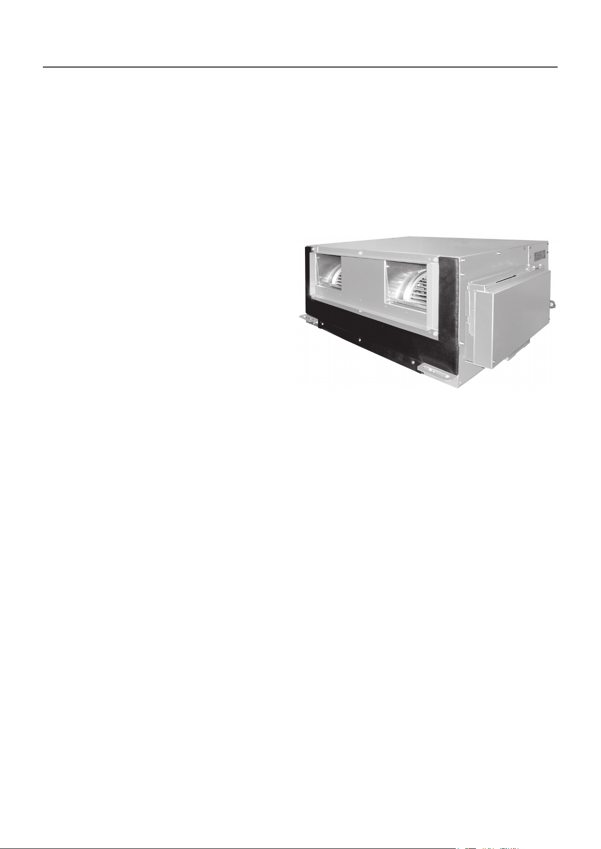
High Static Ducted type
MMD-AP0304H2UL
MMD-AP0364H2UL
MMD-AP0484H2UL
MMD-AP0724H2UL
MMD-AP0964H2UL
Contents
1. Specifications
2. Dimensions
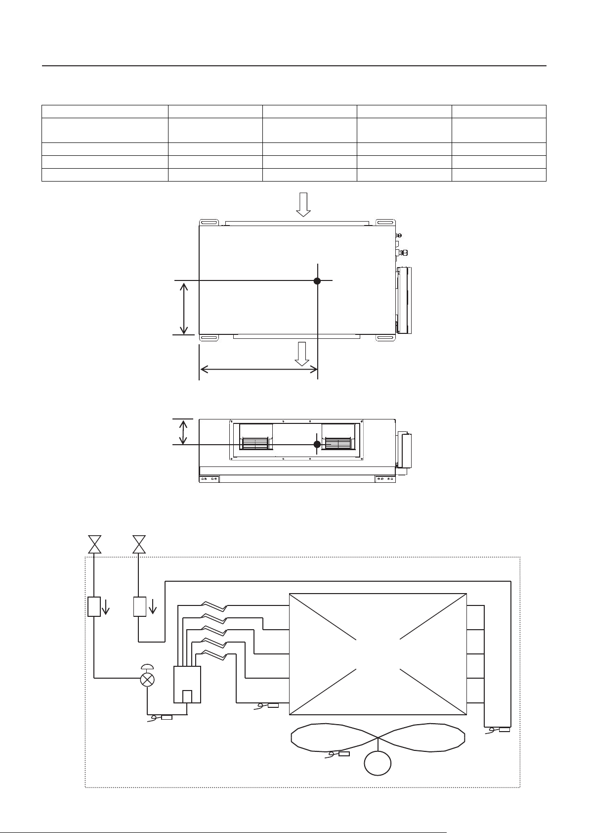
3. Center of gravity
4. Piping diagram
5. Wiring diagram
6. Electrical current characteristics
7. Sensible capacity table
8. Fan characteristics
9. Sound data
1
MMD-AP___4H2UL E15-3H1
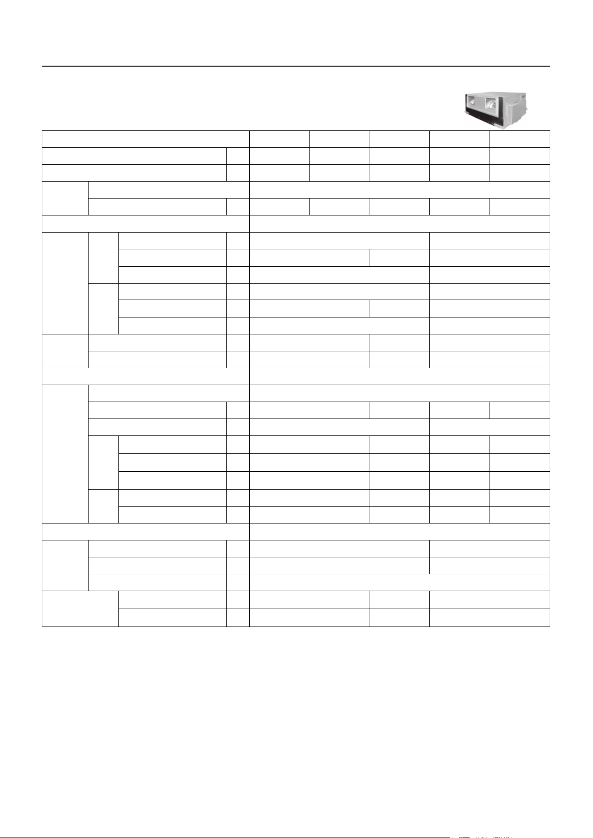
1. Specifications
Concealed Duct High Static Pressure type
Model name MMD- AP0304H2UL AP0364H2UL AP0484H2UL AP0724H2UL AP0964H2UL
Cooling Capacity
Heating Capacity
kBtu/h
kBtu/h
30 36 48 72 81
34 40 54 96 108
Electrical
characteristics
Appearance Zinc hot dipping steel plate
Dimension
Total weight
Heat exchanger Finned tube
Fan unit
Air filter Field supply
Power supply 230 V (208/230 V) 1phase 60 Hz
Power consumption (208/230 V) kW 0.38/0.41 0.38/0.41 0.35/0.41 1.37/1.44 1.20/1.63
Height In 15.0 18.5
Unit
Packing
Unit lbs 128 154 362
Packed unit lbs 141 176 417
Fan Centrifugal fan
Standard air flow cfm 926 1235 2120 2473
Motor W 260 370 × 3
External
static
pressur
e (*1)
Air flow
limit
Width In 33.5 47.2 54.3
Depth In 26.0 49.2
Height In 17.0 24
Width In 42.6 56.4 61.8
Depth In 31.9 55.3
Factory default (208/230 V)
208 V (High tap/Mid tap/Low tap)
(*3)
230 V (High tap/Mid tap/Low tap)
(*3)
Lower limit cfm 755.2 988.2 1766 2473
Upper limit cfm 1132.8 1447.1 2002 2944
In
WG
In
WG
In
WG
0.641/0.814 0.296/0.519 0.580/0.929 0.317/0.734
1.075 - 0.641 - 0.287
1.175 - 0.814 - 0.506
0.606 - 0.296 - Non
0.801 - 0.519 - 0.114 1.12 - 0.929 - 0.29 1.099 - 0.734 - 0.459
0.896 - 0.580 - 0.346 0.739 - 0.317 - 0.062
Gas side In 5/8" 7/8"
Connecting
pipe
Sound pressure level
(*2)
Liquid side In 3/8" 1/2"
Drain port (Nominal dia.) In VP25 (Polyvinyl chloride tube: External Dia.1-1/4 Internal Dia.1)
208 V (High tap/Mid tap/Low tap)
(*3)
230 V (High tap/Mid tap/Low tap)
(*3)
dB(A) 49.5/45/41 47/44/- 49.5/45/41
dB(A) 51/47/43 49/46/43 51/47/43
Note
(*1) Non attached filter
(*2) The actual values in an external operating environment are generally higher than the indicated values due to the contribution from ambient
noise.
(*3) The tap is set by wire connection change of fan motor.
2
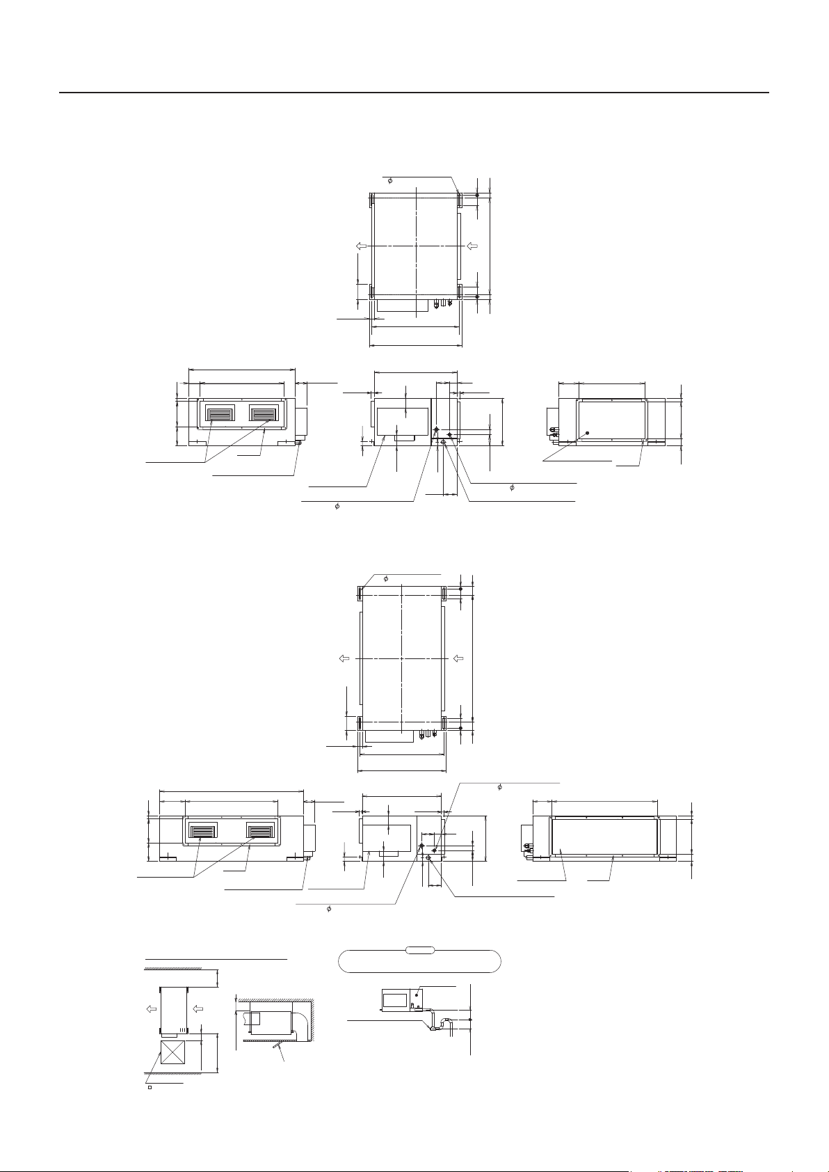
2. Dimensions
MMD-AP0304H2UL, AP0364H2UL
Ho
4- 0.5"(12)x3.6"(92)
4.7"(120)
MMD-AP___4H2ULE15-3H1
l
e
o
for
g
lt
ingb
han
0.8"(20)
3.1"(80)3.1"(80)0.8"(20)
31.5"(800)
(Hanging bolt mountingpitch)
Unit external dimension
3.4"
(87) 26.5"(672)
8"(202) 1"(25)
6"
(154)
Air disc harge port
MMD-AP0484H2UL
33.5"(850)
Flange
Entering of power supply
and communica tion wires
1.6"(40)
(Hanging bolt mou ntin
Unit externaldimensio
3.8"(96)
1"(25)
1.4"(35)
Electrical
control box
Refriger ant pipe connecting port
(Gas s
ide 5/8"(15.
4.7"(120)
9))
Hole for hanging bolt
4-0.5"(12)x3.6"(92)
27.6"(700)
29.1"(740)
26"(660)
2.9"
(73)
3.4"(87)
g
4.1"(105)
1.2"(30)
4.3"
(110)
pitch
1"(25) 1"(25)
)
n
2.4"(60)
1"(25)
1.6"(40)
15"(380)
3.5"(90)
Refrigerant pipe connecting port
(Liquid side 3/8"(9.5))
Drainpipeconnecting port(VP25)
(Male screw)
2.8"(70)
3.1"(80) 0.8"(20)
41.7"(1060)
(Hanging bolt mounting pitch)
3.1"(80)0.8"(20)
.
6
4"
(163)
Air suction port
20.7"(526)
Flange
1.2"
2.3"
(59) 11.5"(292) (30)
Unitexternal dimensio
8.3"(212)
8"(202) 1"(25)
6"
(154)
Airdischargepo
Space required for installationor service work
Checkport
23.6"(600
47.2"(1200)
rt
19.7"
(500)
31.5"(800)
7.9"(200)
)
n
30.4"(772)
Flange
Enteringofpower supply
andcommunication wires
e
Servic
space
or more
Distance from building
or more
5.9"(150)
Service
or more
s
e
pac
1.6"(40
3.8"(96
(25
1"
Electrical
control box
Refrigerant pipeconnecting port
(Gassi
de 5/8"(15.9
t
Checkpor
)
27.6"(700)
(Hangingbolt mounting pitc
29.1"(7
Unit external dimensio
)
))
ca
usegarbagei
Plug
3.4"
2.9"
(87)
26"(660)
(73)
lug
ndrai
andto
)
1.4"(35)
Besuretoset the p
be
(Check and cleaningport
40)
n
1"(25)
4.1"
(105)
4.3"
(110)
1.2"(30)
n
n
Atte
io
t
eittobeableto cleaning,
mak
n
piles
piping
Checkpanel
)
3
2.8"(70)
)
h
ant
R
pipeconnectin
efriger
dside
(Liqui
3/8"(9.5))
2.4"
(60)
1.6"(40)3.5"(90)
15"(380)
Drain pipe connecting port(VP25)
(
screw)
Male
intr
n
ap
dr
upeasily
.
a
i
or more
3.9"(100)
or more
2"(50)
g
ort
p
.4
6
"
(163)
rt
Air suction p
o
<Note>
1. Indoor unit does not have air filter its inside.
So be sure to set an air filter (local
arrangements) in the position maintained
easily such as a air intake grille.
(If there is no air filter, dusts are blocked in the
air heat exchanger and it may cause failure or
water leak in air-conditioner.)
2. Leave sufficient space to remove the air filter
when you attach it.
4.5
3
Flange
"
(876)
1.2"
2.3"
(59) 11.5"(292) (30)
MMD-AP___4H2UL E15-3H1
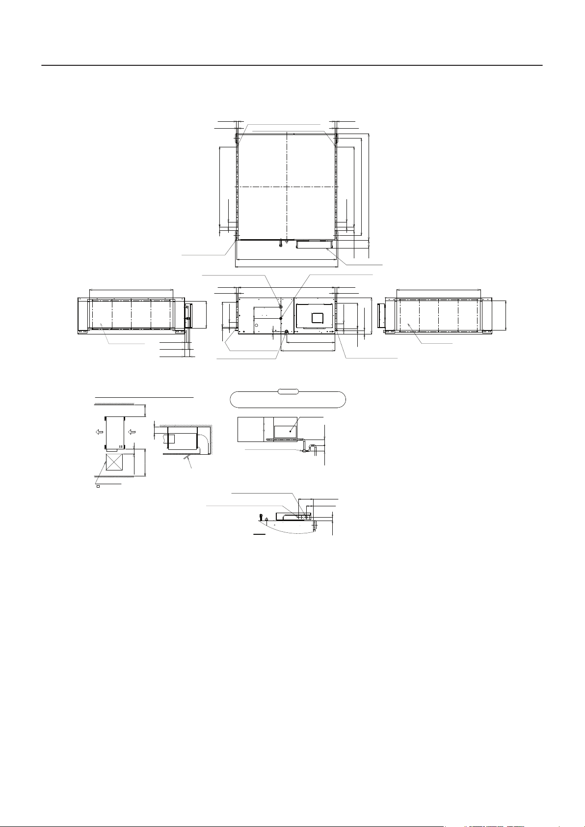
MMD-AP0724H2UL, MMD-AP0964H2UL
Hole for hanging bolt
(4-Ø1/2"(12)×3.6"(92))
42.6"(1083) Outside
7.9"
7.9"(200)
Service
space
(200)
or more
5.9"(150)
Service
or more
space
39.4"(1000)
or more
0.9"(22)
1.8"(46)
2.6"(65)
Distance from building
Check port
Air discharge port
Space required for installation or service work
Check port
23.6"(600)
1"(25) 1"(25)
0.6"(15)
2.6"(65)
1.8"(45) 2.6"×16=40.9"(65×16=1040)
Refrigerant pipe connecting port
(Gas side Ø7/8"(22.2) Brazed)
0.6"(15)
2.6"(65)
Outside
13.7"(347)
(65×5=325)
2.6"×5=12.8"
Screw hole for duct mounting
0.4"(9.5)
(6-M5)
Drain pipe connecting port(V25)
Taper screw for R1,1"(25.4) pipes
Be sure to set the plug and to make it to be able to cleaning,
because garbage in drain piping piles up easily in drain trap.
Ø1"(26) Hole for control wire
Ø7/8"(22.2) Hole for power supply cable
Screw hole for duct mounting(17-M5)
Screw hole for duct mounting(17-M5)
50.7"(1288) Hanging bolt mounting pitch
52.3"(1328)
49.2"(1250)
5.9"
(150)
7.9"
(200)
(31)
1.2"
27.5"(698)
Attention
Plug
(Check and cleaning port)
and remote control wiring
0.6"(15)
Refrigerant pipe connecting port
(Liquid side Ø1/2"(12.7) Flared)
24.6"(624)
Check panel
7.8"(198.5)
3.6"(91.5)
3.9"(100)
or more
2"(50)
or more
1"(25)1"(25)
0.6"(15)
2.6"(65)
54.3"(1380)
2.6"×16=40.9"(65×16=1040)
2.6"(65)
49.6"(1260) Hanging bolt mounting pitch
3.9"
(45)
1.8"
(100)
Electric parts box
1.8"(45)
(65×5=325)
18.5"(470)
2.6"×5=12.8"
1"(25)
Screw hole for duct mounting
(6-M5)
<Note>
1. Indoor unit does not have air filter its inside.
So be sure to set an air filter (local
arrangements) in the position maintained
easily such as a suction grills.
(If there is no air filter, dusts are blocked in the
air heat exchanger and it may cause failure or
water leak in air-conditioner.)
2. Leave sufficient space to remove the air filter
when you attach it.
Unit: in (mm)
42.6"(1083) Outside
Air suction port
Outside
15.1"(383)
Z view
(42)
1.7"
4
MMD-AP___4H2ULE15-3H1
㼅
㼄
㻳
㼆
㻳
Air heat exchanger
at indoor side
Sensor
(TC2)
㹋
Fan
Fan Motor
Sensor
(TCJ)
Sensor
(TC1)
Strainer
Pulse
Motor
Valve
Liquid side
Gas side
Capillary Tube
Sensor
(TA)
3. Center of gravity
Model name X (In) Y (In) Z (In) Total weight (lbs)
MMD-AP0304H2UL
MMD-AP0364H2UL
MMD-AP0484H2UL 11.4 25.4 7.7 154
MMD-AP0724H2UL 11.4 28.4 8.7 362
MMD-AP0964H2UL 11.4 28.4 8.7 362
11.4 17.7 7.7 128
Air intake
4. Piping diagram
Air discharge
5
 Loading...