

MMD-AP___1HF2ULE15-3S2
MMD-AP0481HF2UL
MMD-AP0721HF2UL
MMD-AP0961HF2UL
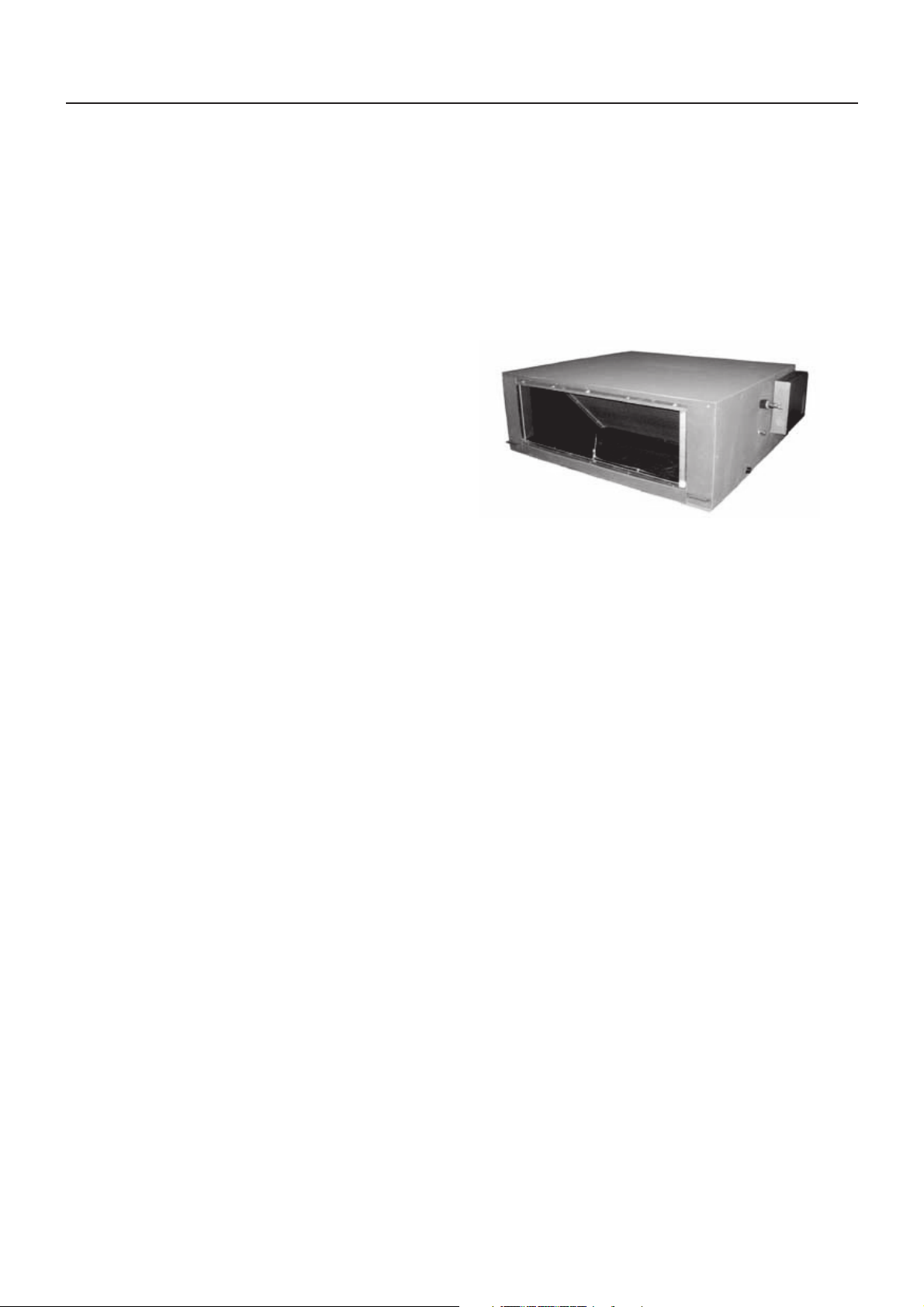
Outside Air Unit Type
Contents
1. System summary
2. Specifications
3. Dimensions
4. Center of gravity
5. Piping diagram
6. System combination
7. Wiring diagram
8. Electrical characteristics
9. Fan characteristics
10. Sound data
1
1. System summary
• Connectable outdoor unit
Outdoor unit of SMMS-e series.
• Corresponding system
Corresponds to a system in which there are the outside air units and the indoor air
conditioners.
• Definition
The outside air unit means an air controller for taken-in outside air.
Intake of the outside air often influences on the system so that the normal control of the air conditioner
becomes difficult or gives a large load upon air controller and cooling performance.
Therefore it is frequently adopted to handle the outside air to a certain condition before the outside air
will enter in the main air conditioner.
This handling device is called an outside air unit.
NOTE:
The outside air unit is an air conditioner provided to handle the outside air load and is not to control
the room temperature. For correspondence to the load of the indoor air controller, set an air
conditioner separately.
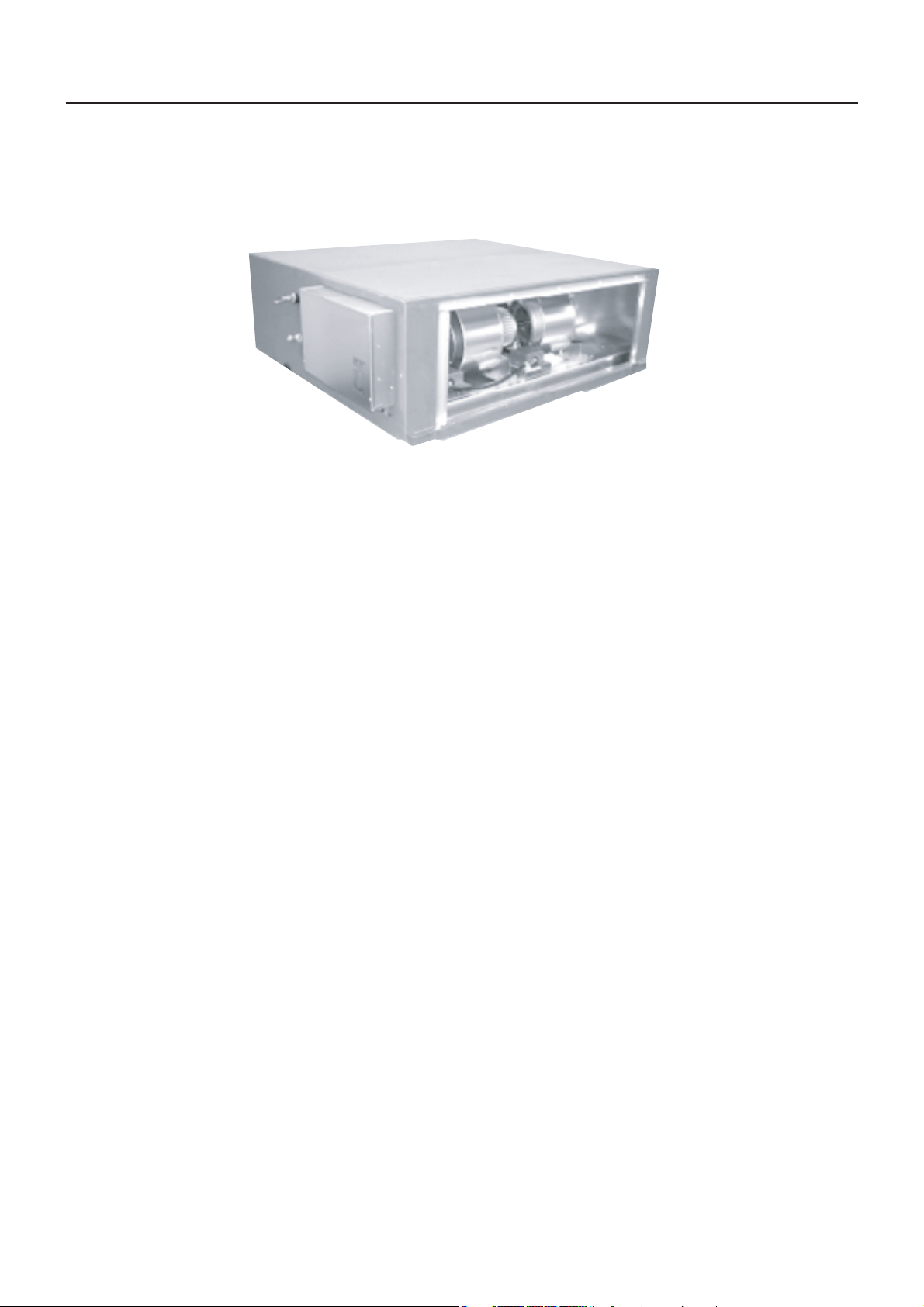
Outside Air Unit Type
MMD-AP___1HF2ULE15-3S2
2
MMD-AP___1HF2ULE15-3S2
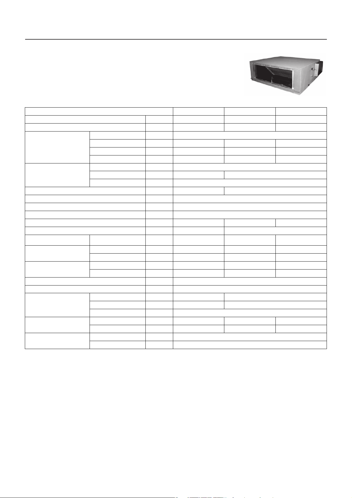
2. Specifications
Model name MMD- AP0481HF2UL AP0721HF2UL AP0961HF2UL
Cooling capacity (Note1)
Heating capacity (Note1)
Power supply 230 V (208/230 V) 1phase
Electrical
characteristics
Outer
dimension
Main unit weight lbs 212 349
Heat exchanger Finned tube
Soundproof / Heat-insulating material Non-flammable insulation
Fan Centrifugal fan
Standard air flow cfm 636 989 1237
Motor W AC 160 AC 160 x 2
External static pressure
(factory default)
External static
pressure
(factory default)
Air flow limit
Air filter Field supply
Controller Wired remote controller
Connecting
pipe
Sound pressure level
Operation
range for SMMS-e
Running current A 1.58/1.56 3.00/2.88 3.32/3.17
Power consumption kW 0.31/0.34 0.56/0.58 0.64/0.66
Starting current A 3.90/3.20 7.70/6.30 8.50/6.90
Height In 19.5"
Width In 35.4" 55"
Depth In 49.8"
208 V / 230 V In WG 0.55/0.86 0.74/1.00 0.41/0.85
208 V (H / M / L) In WG 0.75/0.55/0.16 0.84/0.74/0.24
230 V (H / M / L) In WG 1.06/0.86/0.50 1.08/1.00/0.65
Lower limit cfm 445 693 866
Upper limit cfm 700 1088 1360
Gas pipe In 5/8" 7/8"
Liquid pipe In 3/8" 1/2"
Drain pipe In VP25 (Polyvinyl chloride tube: External Dia.1-1/4 internal Dia.1)
208 V (H / M / L) dB(A) 44/43/36 47/46/40
230 V (H / M / L) dB(A) 46/45/42 48/47/46
Cooling (Note 2)
Heating (Note 3)
kBtu/h 48.0 72.0 96.0
kBtu/h 30.0 47.0 59.0
0.67/0.41
1.01/0.85
°F
°F
41 - 115
23 - 109
47/45
50/49
(H/L)
(H/L)
(H/L)
(H/L)
* The setting temperature is 60 - 80 °F
* Height difference between outside air units must be within 1.97" (0.5 m).
Note 1: Rated conditions Cooling: Outdoor air temperature 91 °F DB/82 °F WB setting temperature 64 °F
Heating: Outdoor air temperature 32 °FDB/26 °F WB setting temperature 77 °F
Note 2: * When supply air temperature is “setting temperature + 5.4 °F” or less, Outside air unit operates as FAN mode.
Note 3: * When supply air temperature is “setting temperature - 5.4 °F” or over, Outside air unit operates as FAN mode.
3

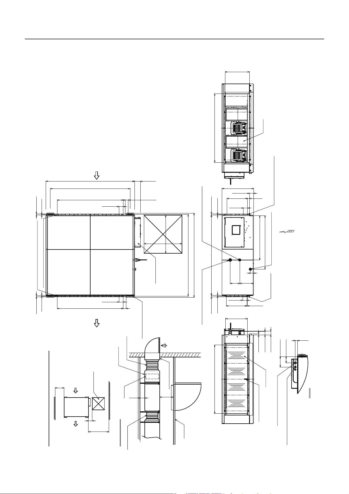
3. Dimensions
Installation Notes
Unit:in(mm)
1. Provide access area to the right of the unit as shown.
2. Condensate piping should slope downwards in the direction of
condensate flow, with a minimum gradient of 1in per 100 inches.
Condensate pipe should be insulated to avoid condensation.
3. Check condensate system for proper drainage before stating the unit.
4. Avoid installation of unit in Hazardous locations.
5. Filter and filter box are field provide and field installed items which
would prevent deposition of duct and dirt in the unit.
6. Install flexible duct for easy disassembly of the unit during major
service or breakdown.
7. Insulating the suction duct is recommended to avoid any
condensation on the exterior from untreated outside air.
8. Outside air louver with screen is recommended at the outside air
operating on the exterior wall.
Access Area
23.6"
(600)
23.6"
(600)
Space required for installation and servicing
Example
Access Area
23.6" (600)
Service
space
Over
7.9"
(200)
Service
space
7.9"
(200)
Over 39.4" (1000)
Outside Air
Unit
Outside Air
Unit
Flexible duct
Filter Box
Filter
Ceiling
Air intake duct
Access Area
Outside air
Over
3.9"
(100)
Over
2.0"
(50)
Air flow
23.0" (583)Outside
15.1" (383)
Outside
Suction
Discharge temp sensor
Discharge
28.7" (728)Outside
13.7" (347)
Outside
0.7" (18)
2.3" (59)
2.5" (65)
2.6" (65)
0.4" (9)
2.6" × 5 = 12.8"
(65 × 5 = 325)
Screw hole for
duct mounting
(6-ø0.2" (5))
1.9"
(49)
8.6"
(218)
5.9"
(150)
27.5" (699)
33.3" (845)
Drain pipe connection port (V25)
Taper screw for R1,1" (25.4) pipes
0.4" (10)
0.8" (20)
49.8" (1266)
0.7" (19)
0.4" (9)
Refrigerant pipe connection port
(Liquid side ø3/8" (9.5) Flared)
Refrigerant pipe connection port
(Gas side ø5/8" (15.9) Flared)
2.6" (65)
1.1"
(28)
2.6" × 5 = 12.8"
(65 × 5 = 325)
2.6" (66)
19.5" (496)
Electrical box
50.7" (1288) Mounting Location
52.3" (1328)
Hole for hanging bolt
(4-ø1/2" (12) × 1.6" (40))
2.6" (65)
2.5" (62)
2.6" × 10 = 25.6"
(65 × 10 = 650)
2.6" (65)
2.2" (55)
2.6" × 8 = 20.5"
(65 × 8 = 520)
32.2" (818) Mounting Location
3.4" (87) 35.4" (898)
0.4" (9)
0.7" (19)
0.4" (9)
0.7" (19)
Screw hole for duct mounting(9-ø0.2" (5))
Screw hole for duct mounting(11-ø0.2" (5))
7.6" (193)
11.8" (299)
1.2" (30)
1.3" (33)
Z
Z view
ø1.2" (30) Hole for control wire
and remote control wiring
ø7/8" (22.2) Hole for power supply cable
Screw hole for duct mounting
(6-ø0.2" (5))
MMD-AP0481HF2UL
MMD-AP___1HF2ULE15-3S2
4
0.7"(18)
2.3"(59)
Discharge temp sensor
Discharge
2.1"(52)
42.6"(1083) Outside
13.7"(347)
Outside
Z
2.6"(65)
2.6"×5=12.8"
(65×5=325)
0.4"(9)
2.6"(65)
1.1"
(28)
2.6"×5=12.8"
(65×5=325)
2.6"(66)
19.5"(496)
27.5"(699)
33.3"(845)
Drain pipe connection port(V25)
Taper screw for R1,1"(25.4) pipes
Screw hole for
duct mounting
(6-Ø0.2"(5))
Screw hole for duct mounting
(6-Ø0.2"(5))
1.9"
(49)
8.6"
(218)
5.9"
(150)
0.4"(10)
0.8"(20) 49.8"(1266) 0.7"(19)
0.4"(9)
Hole for hanging bolt
Refrigerant pipe connection port
(Liquid side Ø1/2"(12.7) Flared)
(4-Ø1/2"(12)×3.6"(92))
Suction
42.6"(1083) Outside
15.1"(383)
Outside
50.7"(1288) Mounting Location
52.3"(1328)
2.6"(65)
1.8"(45) 2.6"×16=40.9"(65×16=1040)
2.6"(65)
1.8"(45)
2.6"×16=40.9"(65×16=1040)
32.2"(818)
Mounting Location
55"(1398)
3.7"(93)
0.4"(9)
0.7"(19)
0.4"(9)
0.7"(19)
Screw hole for duct mounting(17-Ø0.2"(5))
Screw hole for duct mounting(17-Ø0.2"(5))
Refrigerant pipe connection port
(Gas side Ø7/8"(22.2) Brazed)
Access Area
23.6"
(600)
23.6"
(600)
Electrical box
Air flow
Space required for installation and servicing
Example
Access Area
23.6"(600)
Service
space
Over
7.9"
(200)
Service
space
7.9"
(200)
Over 39.4"(1000)
Outside
Air Unit
Outside
Air Unit
Flexible duct
Filter Box
Filter
Flexible duct
Ceiling
Air intake duct
Access Area
Outside air
Over
3.9"
(100)
Over
2.0"
(50)
4.0"(100)
6.6"(166)
1.3"
(33)
Ø1"(26) Hole for control wire
Ø7/8"(22.2) Hole for power supply cable
and remote control wiring
Z view
Installation Notice
1. Provide access area to the right of the unit as shown.
2. Condensate piping should slope downwards in the direction of
condensate flow,with a minimum gradient of 1in per 100 inches.
Condensate pipe should be insulated to avoid condensation.
3. Check condensate system for proper drainage before starting the unit.
4. Avoid installation of unit in Hazardous locations.
5. Filter and filter box are field provided and field installed items which
would prevent deposition of duct and dirt in the unit.
6. Install flexible duct for easy disassembly of the unit during major
service or breakdown.
7. Insulating the suction duct is recommended to avoid any
condensation on the exterior from untreated outside air.
8. Outside air louver with screen is recommended at the outside air
opening on the exterior wall.
Unit: in(mm)
MMD-AP___1HF2ULE15-3S2
5
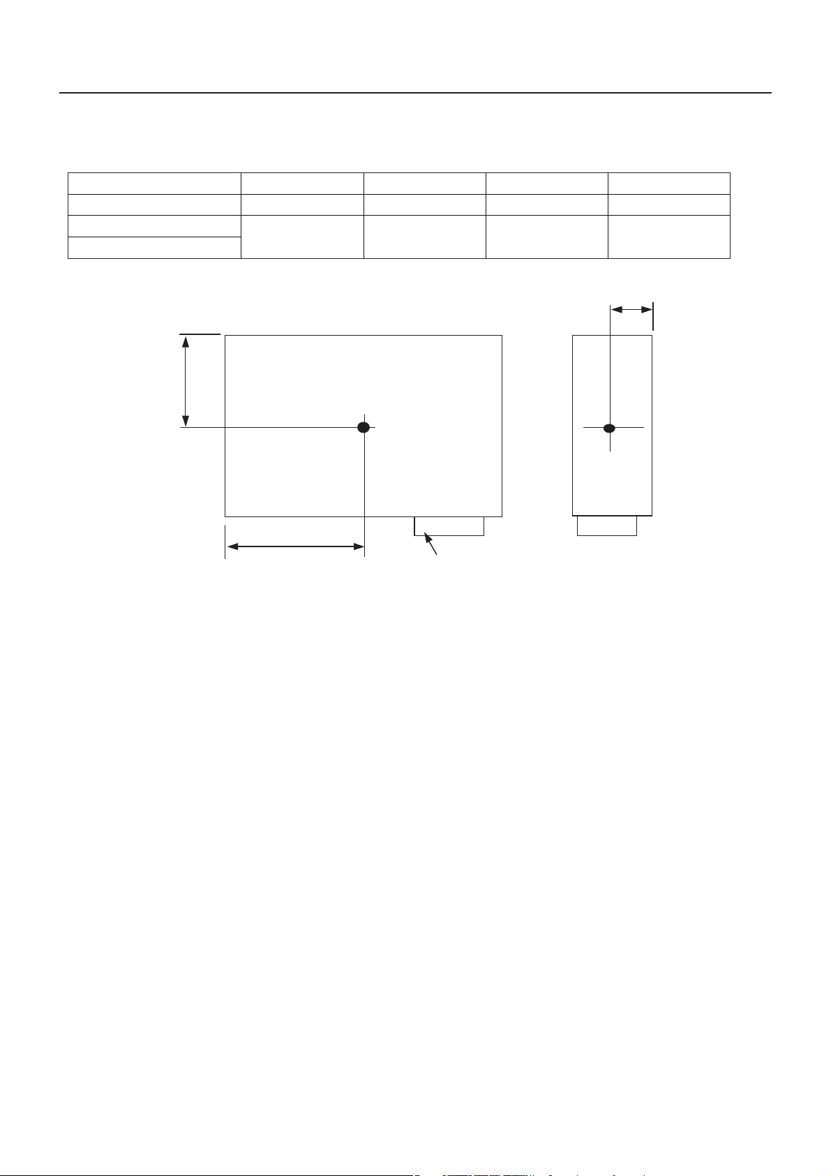
4. Center of gravity
Z
Y
X
Electrical box
Model name MMD-
AP0481HF2UL
AP0721HF2UL
AP0961HF2UL
X (In) Weight (lb)
26.4 18.9 8.7 212
26.4 30.3 8.7 349
Z (In)Y (In)
MMD-AP___1HF2ULE15-3S2
6

5. Piping diagram
M
Liquid side Gas side
Strainer
Pulse Motor
Val ve (PMV)
Sensor
(TC2)
Strainer
Capillary tube
Air heat exchanger
at indoor side
Sensor
(TCJ)
Fan
Sensor
(TA)
Fan motor
Sensor
(TC1)
Sensor
(TF)
MMD-AP___1HF2ULE15-3S2
Functional part name Functional outline
Pulse Motor Valve PMV (Connector CN082 (6P): Blue)
1) Controls super heat in cooling operation
2) Controls sub cool in heating operation
3) Recovers refrigerant oil in cooling operation
4) Recovers refrigerant oil in heating operation
Temp. sensor 1. TA (Connector CN104 (2P): White)
1) Detects indoor suction temperature
2. TC1 (Connector CN100 (3P): Brown)
1) Controls PMV super heat in cooling operation
3. TC2 (Connector CN101 (2P): Blue)
1) Controls PMV sub cool in heating operation
4. TCJ (Connector CN102 (2P): Yellow)
1) Controls PMV super heat in cooling operation
5. TF (Connector CN103 (2P): Green)
1) Detects indoor discharge temperature
7
MMD-AP___1HF2ULE15-3S2
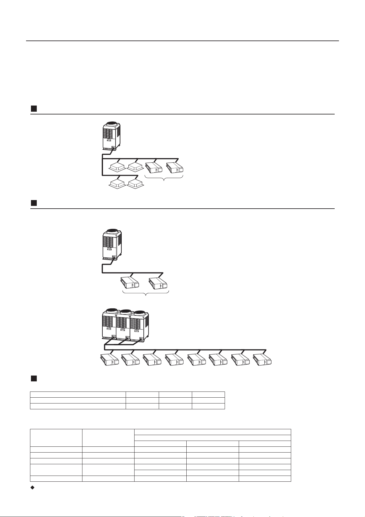
6. System combination 6-1. Case of MMY model
The Outside Air Unit is connectable to SMMS (Super Modular Multi system).
However this is not connectable to SHRM (Super Heat Recovery Multi system).
Keep the height difference between the Outside Air Units to 1.97" (0.5 m) or less.
Case of Outside Air connection with other indoor units
Connection which stretches over two floors is unavailable units
Correct
Height difference: 1.97" (0.5 m) or less
Case of All Outside Air connection to SMMS-e
• System that connected to Outside Air Unit only can be used with only single Outdoor unit on one line of the multi system.
The combination of indoor units is only available specified in following Table 2.
Correct
Height difference: 19.7" (0.5 m) or less
Incorrect
The combination of Indoor units
1. The capacity code of Indoor unit is decided for each capacity type.
emanledomtinuroodnI
pytyticapactinuroodnI
apactinuroodnI
ocytic
2. Combination of Indoor units is decided for Outdoor unit capacity type.
It allows only the combinations of Indoor units below.
Outdoor unit capacity type Outdoor unit capacity code
epyt270
7
441epyt441
861epyt861
Combination of Indoor unit capacity type
1
2702
69069epyt690
-021epyt021
-
-
-
Please refer to “Outside Air Unit’s Installation Manual” except the above contents.
690270840e
692784ed
Number of Indoor units
270
LU2FH1690PALU2FH1270PALU2FH1840PA-DMM
32
--
840+840
270+
70+690
-
-840+270
840+840+840
-840+690
02
840+840+27
8
MMD-AP___1HF2ULE15-3S2
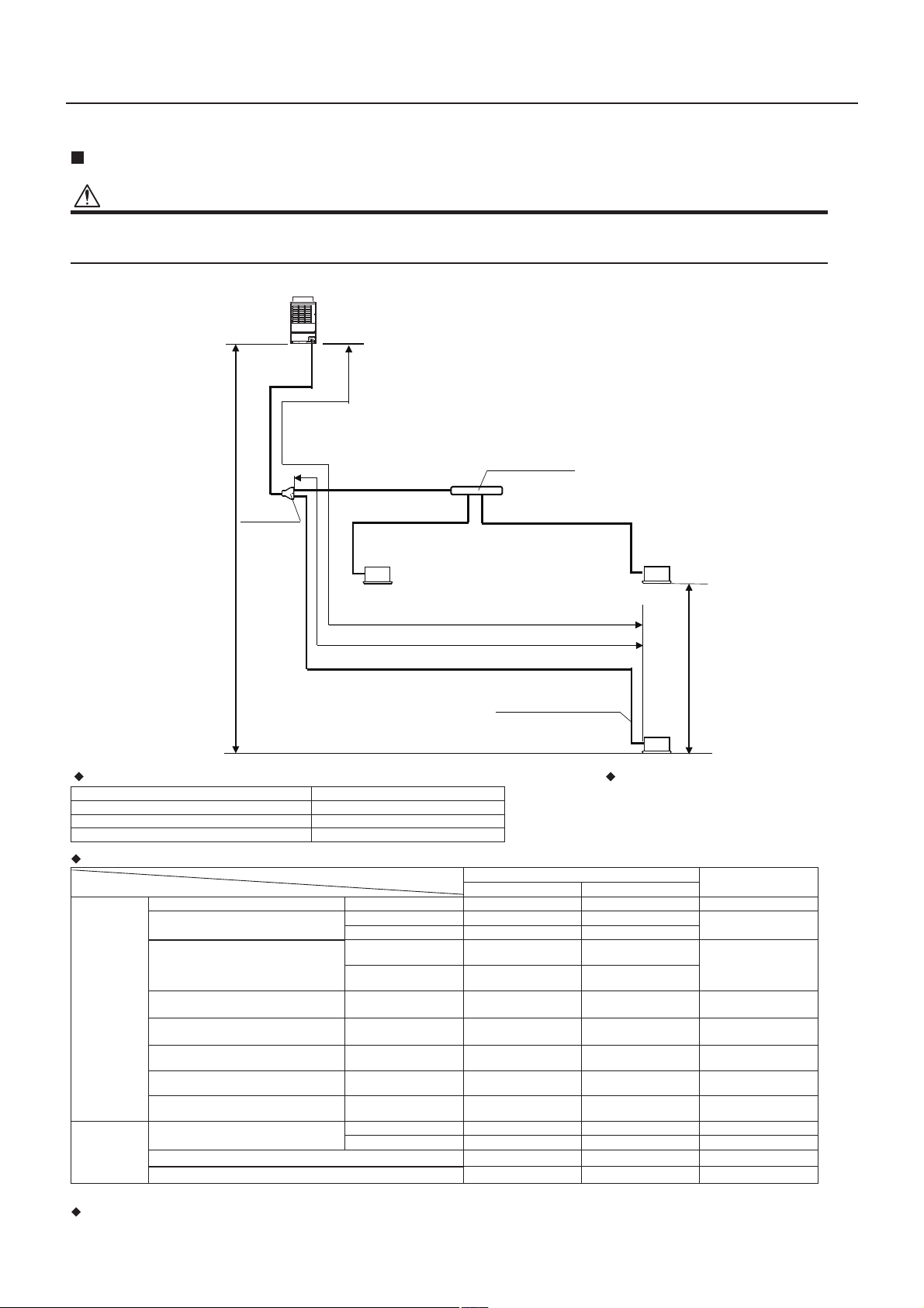
Allowable length/height difference of refrigerant pipinJ&DVHRI$OO2XWVLGH$LU
CAUTION
Length and height of refrigerant piping keep the limitation blow.
If installed in out of the limitation, there is a possibility that heat-exchanger in Outdoor unit will burst and leak a refrigerant gas, for freezing heat-exchanger by shortage
of defrosting capacity.
Allowable length and height difference of refrigerant piping
(*1): Farthest Indoor unit from the first branching section is the Indoor unit (c).
Please refer to “Outdoor Unit’s Installation Manual” except the above contents.
System restrictions Cautions for installation
Y-shaped branching joint must be installed
horizontally.
Max. No. of combined Outdoor units 1 unit
Max. capacity of combined Outdoor units 14 ton
Max. No. of combined Indoor units 3 units
Max. capacity of combined Indoor units Refer to “ The combination of Indoor units”
Allowable value
Pipes
mtf
Pipe length Total extension of pipe (Liquid pipe) Actual length c + b + a + 2L + 1L003489
Farthest piping length
L (*1)
Equivalent length 051294
L1 + c
Actual length 031724
Main piping length
Equivalent length
Max. 394
0LQ
Max. 120
(Min. )
L1
Actual length
Max. 328
(Min. 164)
Max. 100
(Min. 50)
Farthest equivalent piping length from the first
branching section
Li
(*1)
Equivalent length c0389
Farthest equivalent piping length between
Outdoor units
LO
Equivalent length
Maximum equivalent piping length of Outdoor
unit connecting pipe
Equivalent length
Maximum actual length of pipes connected to
Indoor units
Actual length c ,b ,a0389
Maximum equivalent length between
branching sections
Equivalent length 2L0389
Height difference
Height between Outdoor and Indoor units
H1
Upper Outdoor units 04131
Lower Outdoor units 301
Height between Indoor units
H2
5.02
Height between Outdoor units
H3
Indoor unit
Outdoor unit
Unit (A)
Unit (b)
Branching header
Branching pipe
L2
Indoor unit connecting pipe
Indoor unit
Main
piping
L1
First branching
section
The longest piping length: L 492 ft (150 m)
The longest piping length from the first branch:
Li 98 ft (30 m)
Height difference between
Outdoor and Indoor units:
H1 131 ft (40 m)
Indoor unit connecting pipe
Height difference
between Indoor units:
H2 2 ft (0.5 m)
Unit (a)
b
H2
c
a
H1
Unit (c)
Indoor unit
Max. 100
(Min. 50)
Max. 120
(Min. 50)
Max. 394
(Min. 164)
Max. 328
(Min. 164)
9

MMD-AP___1HF2ULE15-3S2
6-2. Case of MCY model
Case of All Outside Air connection to Side Blow SMMS-e
The combination which can connect Outside Air Unit is only the 1:1 combination of MCY-MAP0487HS-UL and
MMD-AP0481HF2UL.
Other combination is not permitted.
Correct Incorrect
Allowable length/height difference of refrigerant piping (Case of All Outside Air)
CAUTION
Length and height of refrigerant piping keep the limitation blow.
If installed in out of the limitation, there is a possibility that heat-exchanger in Outdoor unit will burst and leak a refrigerant gas, for freezing heat-exchanger by shortage
of defrosting capacity.
Outdoor unit
Height difference between
an outside air unit and an
outdoor unit H3
Main
pipe
L4
Total extension of pipe (liquid pipe, real length) 328 100 L4
Real length
Equivalent length 410 125
Piping Length
Furthest piping length
(=Max.length of main pipe)
Max equivalent length of furthest piping from 1st branching Li ‒ ‒
Max real length of indoor unit connecting pipe ‒ ‒
Height
Difference
Height between indoor and outdoor units H3
Height between indoor units H2 ‒ ‒
Upper outdoor unit 164 50
Lower outdoor unit 9 3
(*1) The minimum piping length should set to the following figure by outside air temperature.
No restrictions (Operation permission)
Piping length 20 m or more
Piping length 50 m or more
No operation permitted
50
Outside air unit
Allowable value
(ft) (m)
Max 328 100
Min (*1) 164/66 50/20
Pipes
L4
41
32
23
Outside air unit temp. [°F] (*2)
14
(*2) Refer to [
-13 -4 5 14 23 32 41 50
■Use conditions] for Outside air unit temperature.
Outdoor unit temp. [°F]
◆Please refer to “Outdoor Unit’s Installation Manual” except the above contents.
10

6-3. Installation
Connecting flange
Refer to size in the figure attached to the main unit.
REQUIREMENT
If the air conditioner unit and the canvas joint are connected with the rivets, the fan and the refrigerating cycle cannot
be checked.
Be sure to use the flange as shown in the above and tighten it by the bolts.
(Fixing bolts 0.2" x 0.5"LQ (6 x 12 mm), locally procured)
<MMD-AP048 type>
<Air supply port connecting flange>
<MMD-AP072 type, AP096 type>
<Air supply port connecting flange>
<Air intake port connecting flange> <Air intake port connecting flange>
42.6" (1083)
25.6" (650) (2.6" × 10 (65 × 16))
2.6" (65)
1.8"
(45)
0.7" (19)
0.4" (9)
2.6" (65)
13.7" (347)
0.4" (9)
12.8" (325) (2.6" × 5 (65 × 5))
0.4" (9)
0.7" (19)
42.6" (1083)
40.9" (1040) (2.6" × 16 (65 × 16))
2.6" (65)
1.8"
(45)
0.7" (19)
0.4" (9)
2.6" (65)
13.7" (347)
0.4" (9)
12.8" (325) (2.6" × 5 (65 × 5))
0.4" (9)
0.7" (19)
23.0" (583)
20.5" (520) (2.6" × 8 (65 × 8))
2.6" (65)
2.2"
(55)
0.7" (19)
0.4" (9)
2.6" (65)
15.1" (383)
1.1" (28)
12.8" (325) (2.6" × 5 (65 × 5))
0.4" (9)
0.7" (19)
42.6" (1083)
40.9" (1040) (2.6" × 16 (65 × 16))
2.6" (65)
1.8"
(45)
0.7" (19)
0.4" (9)
2.6" (65)
15.1" (383)
1.1" (28)
12.8" (325) (2.6" × 5 (65 × 5))
0.4" (9)
0.7" (19)
Unit: in (mm)
MMD-AP___1HF2ULE15-3S2
11

MMD-AP___1HF2ULE15-3S2
<Example of construction>
1
Air intake duct
Connect the air intake duct (Locally procured) to the inlet flange.
Wrap aluminum tape around connecting part between the air intake port flange and duct, or provide sealer
so that air does not leak.
For the outside air intake port, attach a hood so that outside air is sucked from lower side.
And attach wire netting, etc. to the air intake of the hood.
Set the air intake duct at descending inclination so that water
can be dr
ained even if rainwater enters in.
Wrap the outside of the intake duct with heat insulator because it intakes cold air while heating.
2
Air supply duct
Connect the air supply duct (Locally procured) to the Air supply flange.
Wrap aluminum tape around connecting part of the air supply port flange and duct or apply packing so that air
does not leak.
Wall
*1: Locally procured
Access Area
(23.6" × 23.6" in
(600 × 600 mm))
*1
Heat insulator *1 Flexible duct *1
Product main unit
Air supply duct *1
Air supply flange
*1
Air intake flange
*1
Filter Box *1
Flexible duct *1
Hood
(with wire netting)
*1
Air intake duct
*1
Descending
inclination
High-efficiency filter *1
Long life prefilter *1
Heat insulator *1
12

MMD-AP___1HF2ULE15-3S2
Selection of installation place
Avoid installing in the following places.
Select a location for the indoor unit where the cool or warm air will circulate evenly.
Avoid installation in the following kinds of locations.
Locations where inside the ceiling is used as route for outside air.
Saline area (coastal area)
Locations with acidic or alkaline atmospheres (such as areas with hot springs, factories where chemicals or
pharmaceuticals are made and places where the exhaust air from combustion appliances will be sucked into the
unit).
Doing so may cause the heat exchanger (its aluminum fins and copper pipes) and other parts to become
corroded.
Locations with atmospheres with mist of cutting oil or other types of machine oi
l.
Doing so
may cause the heat exchanger to become corroded, mists caused by the blockage of the heat
exchanger to be generated, the plastic parts to be damaged, the heat insulators to peel off, and other such
problems to result.
Places where iron or other metal dust is present. If iron or other metal dust adheres to or collects on the interior
of the air conditioner, it may spontaneously combust and start a fire.
Locations where vapors from food oils are formed (such as kitchens where food oils are used).
Blocked filters may cause the air conditioner’s performance to deteriorate, condensation to fo
rm, the plasti
c parts
to be damaged, and other such problems to result.
Locations near obstructions such as ventilation openings or lighting fixtures where the flow of the blown air will
be disrupted (a disruption of the air flow may cause the air conditioner’s performance to deteriorate or the unit to
shut down).
Locations where an in-house power generator is used for the power supply.
The power line frequency and voltage may fluctuate, and the air conditioner may not work properly as a result.
On truck cranes, ships or other moving conveyances.
The air conditioner must not be used for special applications (such as for storing food, plants, precision
instruments or art works).
(The
quality of the
items stored may be degraded.)
Locations where high frequencies are generated (by inverter equipment, in-house power generators, medical
equipment or communication equipment).
(Malfunctioning or control trouble in the air conditioner or noise may adversely affect the equipment’s operation.)
Locations where there is anything under the unit installed that would be compromised by wetness.
(If the drain has become blocked or when the humidity is over 80%, condensation from the indoor unit will drip,
possibly causing damage to anything underneath.)
Locations where organic solvents are being used.
T
he air conditioner
cannot be used for liquefied carbonic acid cooling or in chemical plants.
Location near doors or windows where the air conditioner may come into contact with high-temperature, high-
humidity outdoor air.
(Condensation may occur as a result.)
Locations where special sprays are used frequently.
13

Installation space
Keep the space necessary for installation and service.
REQUIREMENT
The Access Area should be îLQ (600 × 600 mm).
Unit: in (mm)
Installation under atmosphere of the high humidity
Although it has been confirmed that no trouble occurs on the unit, there is a fear of drip of the water if operation
under high humidity condition continues.
In some cases including the rainy season, especially inside of the ceiling may become high-humidity atmosphere
(dew-point temperature: 86 °F (30 °C) (humidity: 80%) or higher).
1
Installation to inside of the ceiling with tiles on the roof.
2
Installation to inside of the ceiling with slated roof.
3
Installation to inside of the ceiling with kitchen.
In the above cases, additionally attach the heat insulator (Glass wool, etc.) to all positions of the air
conditioner, which come to contact with the high-humidity atmosphere.
In this case, arrange the side plate (Service panel) so that it is easily removed.
Apply also heat insulating a sufficient thickness 0.39"LQ (10 mm) or more to the duct and connecting part of
the duct.
7.9" (200) or more
Electrical box
Access Area
Access Area
39.4" (1000) or more
23.6"
(600)
7.9" (200)
23.6" (600)
2.0" (50)
or more
3.9" (100) or more
Service panel
Duct
MMD-AP___1HF2ULE15-3S2
14

MMD-AP___1HF2ULE15-3S2
Use conditions
In “COOL” mode, if temperature of the outside air is under the setup temp. +5.4°F, FAN status is automatically made. When temperature of the outside air is under 66°F,
FAN status is also made regardless of the setup temperature.
In “HEAT” mode, if temperature of the outside air is over the setup temp. -5.4°F, FAN status is automatically made. When temperature of the outside air is over 59°F,
FAN status is also made regardless of the setup temperature.
REQUIREMENT
In “COOL” or “FAN” mode, if temperature of the outside air is under 41°F, the operation stop automatically in order to protect the equipment.
In this case, continue the operation by selecting “HEAT” mode.
In “HEAT” mode, if temperature of the outside air is under 23°F, the operation stops automatically in order to protect the equipment.
When operating the air conditioner with the outside air temp. under 23°F (minimum -4°F),
set temp. of the outside air to be taken in to 32 (*1)°F or upper using
a duct heater (locally procured).
For details, consult the dealer which you
purchased the air conditioner.
(*1) When 096type system with 1 indoor unit, be taken in to 41°F or upper using a duct heater.
In “HEAT” mode, if temperature is out of range in the Use condition, the fan of the Outside Air Unit intermittently operate. So take care not to overheat a duct heater,
when use a duct heater.
Please refer to “Outside Air Unit’s Owner’s Manual” except the above contents.
14 221401688605234-
51114
23
23-4
109
109
▼
▼
▼
▼
▼
▼
Outdoor Air Temperature °F
Setup temp.
Setup temp.
COOL mode
(Outside Air Unit
and Outdoor Unit)
CoolingFan
Automatic COOL
operation starts
Automatic HEAT
operation starts
HEAT mode
(Outside Air Unit)
Heating
Fan
Setup temp. +5.4°F
Setup temp. -5.4°F
Setup temp.
Automatic HEAT
operation starts
Heating
Fan
Setup temp. -5.4°F
Using duct heater
HEAT mode
(Outdoor Unit)
Outside Air Unit Outside air temp.
Duct heater
(locally procured)
14
23
32
41
50
-13 -4 5 14 23 32
14
23
32
41
50
-13 -4 5 14 23 32
Use condition
Outside air unit temp. [°F]
Outdoor unit temp. [°F]
Use condition
Outside air unit temp. [°F]
Outdoor unit temp. [°F]
aC )ii(metsys dradnats fo esaC )i( se of 096type system with 1 indoor unit
Case to use in SMMS-e “MMY-MAP___6HT_P-UL” and Side blow SMMS-e “MCY-MHP___7HS-UL”
6-4. Basic operation
15

MMD-AP___1HF2ULE15-3S2
REQUIREMENT
When the air conditioner is used for the first time, it will take some moments after
the power has been turned on before the remote control becomes available for
operations: This is normal and is not indicative of trouble.
• Concerning the automatic addresses (The automatic addresses are set up by
performing operations on the outdoor interface circuit board.)
While the automatic addresses are being set up, no remote control operations
can be performed. Setup takes up to
10 minutes (usually about 5 minutes).
• When the power is turned on after automatic address setup
It takes up to 10 minutes (usually about 3 minutes) for the Outdoor unit to start
operating after the power has been turned on.
Before the air conditioner was shipped from the factory, all units are set to
[STANDARD] (factory default). If necessary, change the Indoor unit settings.
The settings are changed by operating the wired remote control.
* The settings cannot be changed using only a wireless remote control, simple
remote control or group control remote control by itself so install a wired remote
control separately as well.
Basic procedure for changing settings
Change the settings while the air conditioner is not working.
(Stop the air
conditioner before making settings.
)
CAUTION
Case of RBC-AMT32UL
Set only the CODE No. shown in the following table: Do NOT set any other CODE No.
If a CODE No. not listed is set, it may not be possible to operate the air conditioner
or other trouble with the product may result.
1
Push and hold
+ +
buttons simultaneously for at
least 4 seconds. After a while, the display flashes as shown in
the figure. Confirm that the CODE No. is [01].
• If the CODE No. is not [01], push
button to clear the display content,
and repeat the procedure from the beginning. (No operation of the remote
control is accepted for a while after
button is pushed.)
(While air conditioners are operated under the group control, “ALL” is
displayed first. When is pushed, the Indoor unit number displayed
following “ALL” is the header unit.)
2
Each time
button is pushed, Indoor unit numbers in the
control group change cyclically. Select the Indoor unit to
change settings for.
The fan of the selected unit runs and the louvers start swinging. The Indoor
unit for change settings can be confirmed.
3
Specify CODE No. [ ] with “TEMP.” / buttons.
4
Select SET DATA [ ] with “TIME” / buttons.
5
Push
button. When the display changes from flashing to lit,
the setup is completed.
• To change settings of another Indoor unit, repeat from Procedure 2.
• To change other settings of the selected Indoor unit, repeat from
Procedure
3
.
Use
button to clear the settings. To make settings after
button was
pushed, repeat from Procedure
2.
6
When settings have been completed, push
button to
determine the settings.
When button is pushed, flashes and then the display content
disappears and the air conditioner enters the normal stop mode.
(While is flashing, no operation of the remote control is accepted.)
All Outside Air Unit connection setting
When only Outside Air Units connected to Outdoor unit, set the all Outside Air Unit
connection setting at Outside Air Units.
Firstly, follow to the basic operation procedure
(1
2
345)
• The CODE No. in Procedure
3 is [
C8].
• The [SET DATA] in Procedure
4
is [
0000].
Secondary, follow to the basic operation procedure
(3
4
5)
• The CODE No. in Procedure 3
is [
AE
].
• The [SET DATA] in Procedure
4
is [0016
].
Finally, follow to the basic operation procedure
(3456)
• The CODE No. in Procedure
3 is [
AF
].
• The [SET DATA] in Procedure
4
is [
0010
].
1
6
3
2
5
4
(* Display content varies with the Indoor unit model.)
CODE No. SET DATA
0000
8
C
6100E
A
010
0FA
Please refer to “Outside Air Unit’s Inst
allation Manual” except
the above contents.
Applicable controls (Case of All Outside Air with SMMS-e “MMY-MAP__HT_P-UL”)
16

MMD-AP___1HF2ULE15-3S2
Set
<
Yes
No
Return
Continue?
NoYes
DN setting
CODE No. SET DATA
C8 0000
AE 0016
AF 0010
Case of RBC-AMT54E-UL
Room A
12:00
75
Cool
Mode
1
2
1 [ MENU] button
Displays the menu screen.
2 [ CANCEL] button
Functions as indicated on the screen, such as returning to the previous
menu screen.
3 [ ∧ ] button
During normal operation: adjusts the temperature.
On the menu screen: selects a menu item.
4 [ ∨ ] button
During normal operation: adjusts the temperature.
On the menu screen: selects a menu item.
5 [ F1] button
Varies its function according to the setting screen.
6 [ F2] button
Varies its function according to the setting screen.
Fan Speed
3,4
5
6
Field setting menu
1.Test mode
2.Register service info.
3.Alarm history
4.Monitor function
5.Setting louver position
Return
DN setting
Code
(DN) Data
Set
10 0000
Return
<>
Code
(DN) Data
Fix
DN setting
10 0001
Return
<>
Fix
1 Push the [ MENU] button to
display the menu screen.
2 Push and hold the [ MENU]
button and the [
the same time to display the “Field
setting menu”.
Push and hold the buttons for more
than 4 seconds.
∨] button at
3 Push the [ ∧ ] / [ ∨ ]
button to select “7. DN setting” on
the “Field setting menu” screen, then
push the “ Set”
F2] button.
[
The fan and louver of the indoor unit
operate. When the group control is
used, the fan and louver of the
selected indoor unit operate.
Move the cursor to select “Code
(DN)” with the “
[ F1] button, then set “Code
(DN)” with the [
∨ ] button.
Move the cursor to select “Data” with
the “
button, then set “Data” with the [
4 Refer to the Installation Manual
supplied with the indoor unit or
service manual for details about the
Code (DN) and Data.
5 Push the [ MENU] button to set
the other Code (DN) and Data. After
“Continue?” is displayed on the
screen, push the “ Yes”
F1] button.
[
6 Push the “ No” [
F2] button to finish the setting
operation. “ Setting” appears on
the screen for a while, then the
screen returns to the “Field setting
menu” screen.
Pushing the “
selection screen when the group
control is used. Push the [
CANCEL] button on the unit
selection screen to finish the setting
operation. “ Setting” appears on
the screen for a while, then the
screen returns to the “Field setting
menu” screen.
>
>” [ F2]
∧ ] / [ ∨ ] button.
F2] button displays the unit
No
<”
∧ ] / [
No” [
All Outside Air Unit connection setting
When only Outside Air Units connected to Outdoor unit, set the all Outside Air
Unit connection setting at Outside Air Units.
Firstly, follow to the basic operation procedure
(1→2→3→5)
• For the CODE No. in Procedure 3 is [C8].
• For the [SET DATA] in Procedure
Secondary, follow to the basic operation procedure
3 is [0000].
(3→5)
• For the CODE No. in Procedure 3 is [AE].
• For the [SET DATA] in Procedure
Finally, follow to the basic operation procedure
3 is [0016].
(3→6)
• For the CODE No. in Procedure 3 is [AF].
• For the [SET DATA] in Procedure
3 is [0010].
17

When the air conditioner is used for the first time, it will take some moments after
the power has been turned on before the remote control becomes available for
operations: This is normal and is not indicative of trouble.
Concerning the automatic addresses (The automatic addresses are set up by
performing operations on the outdoor interface circuit board.)
While the automatic addresses are being set up, no remote control operations
can be performed. Setup takes up to 10 minutes (usually about 5 minutes).
When the power is turned on after automatic address setup
It takes up to 10 minutes (usually about 3 minutes) for the Outdoor unit to start
operating after the power has been turned on.
Before the air conditioner was shipped from the factory, all units are set to
[STANDARD] (factory default). If necessary, change the Indoor unit settings.
The settings are changed by operating the wired remote control.
* The settings cannot be changed using only a wireless remote control, simple
remote control or group control remote control by itself so install a wired remote
control separately as well.
Change the settings while the air conditioner is not working. (Stop the air
conditioner before making settings.)
Set only the CODE No. shown in the following table: Do NOT set any other CODE No.
If a CODE No. not listed is set, it may not be possible to operate the air conditioner
or other trouble with the product may result.
+ +
If the CODE No. is not [01], push
button to clear the display content,
and repeat the procedure from the beginning. (No operation of the remote
control is accepted for a while after button is pushed.)
(While air conditioners are operated under the group control, !ALL" is
displayed first. When is pushed, the Indoor unit number displayed
following !ALL" is the header unit.)
The fan of the selected unit runs and the louvers start swinging. The Indoor
unit for change settings can be confirmed.
To change settings of another Indoor unit, repeat from Procedure
.
To change other settings of the selected Indoor unit, repeat from
Procedure
.
Use button to clear the settings. To make settings after button was
pushed, repeat from Procedure .
When button is pushed, flashes and then the display content
disappears and the air conditioner enters the normal stop mode.
(While is flashing, no operation of the remote control is accepted.)
(* Display content varies with the Indoor unit model.)
Please refer to “Outside Air Unit’s Installation Manual” except the above contents.
Applicable controls (Case of All Outside Air with Side blow SMMS-e
“MCY-MAP__MHT_7HS-UL”)
REQUIREMENT
•
•
•
•
•
Basic procedure for changing settings
CAUTION
4
3
1
1
52
6
Push and hold buttons simultaneously for at
least 4 seconds. After a while, the display flashes as shown in
the figure. Confirm that the CODE No. is [01].
2
3
4
5
6
Each time button is pushed, Indoor unit numbers in the
control group change cyclically. Select the Indoor unit to
change settings for.
Specify CODE No. [ ] with “TEMP.” / buttons.
Select SET DATA [ ] with “TIME” / buttons.
Push button. When the display changes from flashing to lit,
the setup is completed.
2
2
3
When settings have been completed, push button to
determine the settings.
All Outside Air Unit connection setting
When Outside Air Unit connected to Outdoor unit, set the all Outside Air Unit
connection setting at Outside Air Unit.
Set the data as follows according to basic operation procedure.
(1→2→3→4→5→6)
• The CODE No. in Procedure 3 is [C8].
• The [SET DATA] in Procedure
4 is [0000].
Setting for Outside Air Unit’s fan ON
during defrost
If main piping length is less than 20 m and 50 m, Outside Air Unit must be
set for fan ON during defrost operation.
Without fan ON setting, there is a possibility that heat-exchanger in Outdoor
unit will burst and leak refrigerant gas, for freezing heat-exchanger by
shortage of defrosting capacity.
■Outside Air unit setting
Set the data as follows according to basic operation procedure.
(1→2→3→4→5→6)
• The CODE No. in Procedure 3 is [72].
• The [SET DATA] in Procedure
4 is [0000].
■Outdoor unit setting
Set the SW17-Bit2 "ON" on the Interface P.C. board of the outdoor unit.
CODE No. SET DATA
C8 0000
MMD-AP___1HF2ULE15-3S2
SW17
Interface P.C. board
18

MMD-AP___1HF2ULE15-3S2
Interface P.C. board
SW17
Set
<
Yes
No
Return
Continue?
NoYes
DN setting
CODE No. SET DATA
C8 0000
Case of RBC-AMT54E-UL
Room A
12:00
75
Cool
Mode
1
2
1 [ MENU] button
Displays the menu screen.
2 [ CANCEL] button
Functions as indicated on the screen, such as returning to the previous
menu screen.
3 [ ∧ ] button
During normal operation: adjusts the temperature.
On the menu screen: selects a menu item.
4 [ ∨ ] button
During normal operation: adjusts the temperature.
On the menu screen: selects a menu item.
5 [ F1] button
Varies its function according to the setting screen.
6 [ F2] button
Varies its function according to the setting screen.
Setting for Outside Air Unit’s fan ON
during defrost
If main piping length is less than 20 m and 50 m, Outside Air Unit must be set
for fan ON during defrost operation.
Without fan ON setting, there is a possibility that heat-exchanger in Outdoor
unit will burst and leak refrigerant gas, for freezing heat-exchanger by
shortage of defrosting capacity.
■Outside Air unit setting
Set the data as follows according to basic operation procedure.
(1→2→3→5→6)
• The CODE No. in Procedure 3 is [72].
• The [SET DATA] in Procedure
■Outdoor unit setting
Set the SW17-Bit2 "ON" on the Interface P.C. board of the outdoor unit.
3 is [0000].
Fan Speed
3,4
5
6
Field setting menu
1.Test mode
2.Register service info.
3.Alarm history
4.Monitor function
5.Setting louver position
Return
DN setting
Code
(DN) Data
Set
10 0000
Return
<>
Code
(DN) Data
Fix
DN setting
10 0001
Return
<>
Fix
1 Push the [ MENU] button to
display the menu screen.
2 Push and hold the [ MENU]
button and the [
the same time to display the “Field
setting menu”.
Push and hold the buttons for more
than 4 seconds.
∨] button at
3 Push the [ ∧ ] / [ ∨ ]
button to select “7. DN setting” on
the “Field setting menu” screen, then
push the “ Set”
F2] button.
[
The fan and louver of the indoor unit
operate. When the group control is
used, the fan and louver of the
selected indoor unit operate.
Move the cursor to select “Code
(DN)” with the “
[ F1] button, then set “Code
(DN)” with the [
∨ ] button.
Move the cursor to select “Data” with
the “
button, then set “Data” with the [
4 Refer to the Installation Manual
supplied with the indoor unit or
service manual for details about the
Code (DN) and Data.
5 Push the [ MENU] button to set
the other Code (DN) and Data. After
“Continue?” is displayed on the
screen, push the “ Yes”
F1] button.
[
6 Push the “ No” [
F2] button to finish the setting
operation. “ Setting” appears on
the screen for a while, then the
screen returns to the “Field setting
menu” screen.
Pushing the “
selection screen when the group
control is used. Push the [
CANCEL] button on the unit
selection screen to finish the setting
operation. “ Setting” appears on
the screen for a while, then the
screen returns to the “Field setting
menu” screen.
>
>” [ F2]
∧ ] / [ ∨ ] button.
F2] button displays the unit
No
<”
∧ ] / [
No” [
All Outside Air Unit connection setting
When Outside Air Unit connected to Outdoor unit, set the all Outside Air Unit
connection setting at Outside Air Unit.
Set the data as follows according to basic operation procedure.
(1→2→3→5→6)
• The CODE No. in Procedure 3 is [C8].
• The [SET DATA] in Procedure
3 is [0000].
19

7. Wiring diagram
MMD-AP0481HF2UL
MMD-AP___1HF2ULE15-3S2
PMV
FAN1
GRY
RED
WHI
3
BLK
2
ORN
1
BLU
4P
(WHI)
GRY
GRY
RED
RED
WHI
WHI
208/230-1-60
Power Supply
FM
G&Y
Screw
GRY
RED
WHI
L2
L1
4P
F3 F4
F1 F2
A
(WHI)
BLK
ORN
BLU
EXCT
PNL
TF
TC2 TC1
TCJ
TA
RED
LM
CN033
凚GRN)
凚BLU)
CN068
FAN
CN083凚WHI凛
CN080
凚GRN)
CN103
凚BRW)
CN100
凚BLK)
CN101
凚RED)
CN102
凚YEL)
CN104
凚RED)
CN030
ULL
H M
RY007
P301
BLK
spark killer
43F1
FS
FILTER
凚WHI)
CN070
凚BLK)
CN081
凚GRN)
凚RED)
CN073
MCC-1403
for Indoor Unit
Control P.C. Board
RY001
RY002
RY006
RY004
CN304凚GRY)
WHI
RY005
CN309
凚YEL凛
Power
Fuse
ACIN
RED
supply
T5.0A傍
傍傍傍傍傍250V到
WHI
CN082
circuit
CN067凚BLK)
凚BLU)
CN066凚WHI)
CN060凚WHI)
凚WHI)
CN032
CN061凚YEL)
凚WHI)
CN075
CN074凚WHI)
CN050凚WHI)
CN041凚BLU)
CN040
凚BLU)
CN044凚BRW)
FAN OPTION
DRIVE
T10
RC
OC
EMG
CN02
凚YEL)
BLK
BLK
BLU
BLU
CN01
凚WHI)
MCC-1520
Sub P.C.Board
Line Filter
WHI
RED
TR1
Remote
Controller
A B
Remote
Outdoor
RED
43F1
Board
Controller
Unit
WHI
Connector
46
WHI
F1
RED
RED
T10A,250V到
5
Indoor
43F1
RC
3
Unit
Ground
Fan Motor
Parts傍Name
Running Capacitor
RC
FM
Symbol
Transformer
TR1
Temp sensor
Blow temp. sensor
Intake air temp. sensor
TF
TA
Drain Control Relay
Fan Motor Control Relay
RY002
RY005~007
TC1,TC2,TCJ
Pulse Motor Valve
Fuse for Fan Motor
Fan Motor Control Relay
PMV
F1
43F1
凵刁凾刁刄
击凶凷刀分击凸击凵凳分击刁刀
刄凷凶凬刄凷凶
刋凷凾凬刋凷凾凾刁刉
刉出击凬刉出击分凷
凹刄刋凬凹刄凳刋
凴凾函凬凴凾凳凵函
凴凾切凬凴凾切凷
Fan motor inside
刂刀函凬刂击刀函
刁刄刀凬刁刄凳刀凹凷
凴刄刉凬凴刄刁刉刀
凹凙刋凬凹刄凷凷刀凙刋凷凾凾刁刉
20
ORN
BLU
wiring diagram
BLK
WHI
49F
RED
GRY
protection switch
Motor over heating
1.佘 indicates the terminal block.
number as figure and lead wire's color of fan motor.
Letter at inside indicates the terminal number.傍
exchange the lead wire of arrow ( ) position after check the terminal
4. A position is connected to terminal block when change to static pressure.
3. indicates the control P.C board.
2.A dotted line and broken line indicate the wiring at site.

MMD-AP___1HF2ULE15-3S2
number as figure and lead wire's color of fan motor.
exchange the lead wire of arrow ( ) position after check the terminal
4. A position is connected to terminal block when change to static pressure.
3. indicates the control P.C board.
2.A dotted line and broken line indicate the wiring at site.
Letter at inside indicates the terminal number.傍
49F
Motor over heating
protection switch
ORN
BLU
RED
GRY
WHI
BLK
Fan motor inside
wiring diagram
凵刁凾刁刄
刄凷凶凬刄凷凶
刋凷凾凬刋凷凾凾刁刉
刉出击凬刉出击分凷
击凶凷刀分击凸击凵凳分击刁刀
凹刄刋凬凹刄凳刋
刂刀函凬刂击刀函
凹凙刋凬凹刄凷凷刀凙刋凷凾凾刁刉
凴刄刉凬凴刄刁刉刀
凴凾函凬凴凾凳凵函
刁刄刀凬刁刄凳刀凹凷
凴凾切凬凴凾切凷
Fuse for Fan Motor
Fan Motor Control Relay
Pulse Motor Valve
Drain Control Relay
Fan Motor Control Relay
Temp sensor
Blow temp. sensor
Intake air temp. sensor
Transformer
Running Capacitor
Fan Motor
Parts傍Name
F1
43F1
Symbol
FM
RC
TR1
TA
TF
TC1,TC2,TCJ
RY005到007
RY002
PMV
MCC-1403
F3
(RED)
CN102
CN061(YEL)
Control P.C. Board
for Indoor Unit
Line Filter
Fuse
T5.0A 250V〜
F2
F1
FM2
8
WHI
WHI
RED
RY005
RY006
ULL
MH
RY007
6
43F2
43F1
RY001
RY002
L2
L1
43F2
BLK
ORN
BLU
FAN2
(BLU)
4P
GRY
RED
WHI
GRY
RED
WHI
WHI
RED
WHI
RED
F2
F1
RED
RED
BLK
BLK
BLU
BLU
Unit
Outdoor
RC
OC
EMG
(BLU)
CN068
(GRN)
CN033
LM
FS
(RED)
CN030
(YEL)
CN104
T10
CN075
(WHI)
CN074(WHI)
CN050(WHI)CN041(BLU)
CN040
(BLU)
CN044(BRW)
CN066(WHI)
CN067(BLK)
WHI
ACINRED
(YEL)
CN309
RY004
CN304(GRY)
P301
CN083(WHI)
FAN
BLK
WHI
WHI
RED
RED
RED
Power
supply
circuit
PMV
F4F3F2
F1
F4
FM1
43F1
FAN1
(WHI)
4P
WHI
RED
GRY
GRY
RED
WHI
ORN
(BLK)
CN101
(BRW)
CN100
PNL
EXCT
(RED)
CN073
FILTER
(WHI)
CN070
(BLK)
CN081
(BLU)
CN082
CN060(WHI)
OPTION
DRIVE
FAN
(WHI)
CN032
TCJ
TA
TC1
TC2
TR1
Sub P.C.Board
MCC-1520
(YEL)
CN02
CN01
(WHI)
spark killer
spark killer
TF
CN103
(GRN)
CN080
(GRN)
AB
Controller
Remote
Remote
Controller
Board
BLU
ORN
BLK
G&Y
G&Y
A
A
RC2
RC1
Power Supply
208/230-1-60
Indoor
Unit
Ground
Screw
GRY
RED
WHI
GRY
RED
WHI
4P
1
(WHI)
3
1
2
WHI
BLU
ORN
BLK
GRY
RED
BLU
4P
32
BLK
ORN
WHI
GRY
RED
(WHI)
43F2
43F1
072type
072type
F3F2
F1
BLK
ORN
BLU
F4
A
096type
F4F3F2
F1
BLU
ORN
BLK
A
096type
RED
RED
5
3 3
5
4
5
4
5
Connector
MMD-AP0721HF2UL, MMD-AP0961HF2UL
21

8. Electrical characteristics
Voltage Range(V) MOCP
Min. Max. kW A A
Power
consumption
FLA MCA
A
Model name
MMD-AP0481HF2UL
MMD-AP0721HF2UL
MMD-AP0961HF2UL
Nominal Voltage
(V-Ph-Hz)
208/230-1-60
MCA : Minimum Circuit Amps FLA : Full load Amps
MOCP : Maximum Overcurrent Protection(Amps) kW : Fan Motor Rated Output (kW)
187
187
187
253
253
253
0.16
0.16 x 2
0.16 x 2
1.84
3.43
3.80
2.30
4.29
4.76
15
15
15
MMD-AP___1HF2ULE15-3S2
22

9. Fan characteristics
230V䚷cfm - A 208V䚷cfm - A
230V䚷Fan characteristics 208V䚷Fan characteristics
㻜
㻜㻚㻞
㻜㻚㻠
㻜㻚㻢
㻜㻚㻤
㻝
㻝㻚㻞
㻝㻚㻠
㻝㻚㻢
㻠㻜㻜 㻡㻜㻜 㻢㻜㻜 㻣㻜㻜
External static pressure (in WG)
Air fl ow ra te (cfm)
㻝
㻝㻚㻝
㻝㻚㻞
㻝㻚㻟
㻝㻚㻠
㻝㻚㻡
㻝㻚㻢
㻝㻚㻣
㻝㻚㻤
㻝㻚㻥
㻞
㻠㻜㻜 㻡㻜㻜 㻢㻜㻜 㻣㻜㻜
Fan motor curre nt (A)
Air fl ow ra te (cfm)
㻜
㻜㻚㻞
㻜㻚㻠
㻜㻚㻢
㻜㻚㻤
㻝
㻝㻚㻞
㻝㻚㻠
㻝㻚㻢
㻠㻜㻜 㻡㻜㻜 㻢㻜㻜 㻣㻜㻜
Ex te rn al sta ti c pr essu re (i n W G)
Air fl ow ra te (cfm)
㻝
㻝㻚㻝
㻝㻚㻞
㻝㻚㻟
㻝㻚㻠
㻝㻚㻡
㻝㻚㻢
㻝㻚㻣
㻝㻚㻤
㻝㻚㻥
㻞
㻠㻜㻜㻡㻜㻜㻢㻜㻜㻣㻜㻜
Fan motor curre nt (A)
Air fl ow ra te (cfm)
Min
445(cfm)
Standard
636(cfm)
Min
445(cfm)
Standard
636(cfm)
Max
700(cfm)
Max
700(cfm)
Highstatic pressure tap
Midstatic pressure tap
Low static pressure tap
Highstatic pressure tap
Midstatic pressure tap
Low static pressure tap
Highstatic pressure tap
Midstatic pressure tap
Low static pressure tap
Highstatic pressure tap
Mid static pressure tap
Low static press ure tap
MMD-AP0481HF2UL
MMD-AP___1HF2ULE15-3S2
23

MMD-AP0721HF2UL
MMD-AP___1HF2ULE15-3S2
230V䚷cfm - A 208V䚷cfm - A
3.8
3.6
3.4
3.2
2.8
2.6
Fan motor curre nt (A)
2.4
2.2
Min
693(cfm)
4
Highs tatic press ure tap
3
2
Mid static pressure tap
Low static press ure tap
600 90 0 12 00
Air flow ra te (cfm )
Standard
989(cfm)
Max
1088(cfm)
Min
693(cfm)
4
3.8
3.6
3.4
3.2
3
2.8
2.6
Fan motor curre nt (A)
2.4
2.2
2
600 900 12 00
Highs tatic press ure tap
Midstatic pressure tap
Low static pressure t ap
Air fl ow ra te (cfm)
230V䚷Fan characteristics 208V䚷Fan characteristics
1.6
1.4
1.2
1
0.8
Mid static pressure tap
0.6
0.4
External static pressure (in.W G)
0.2
0
600 900 1200
Lowstatic pressure tap
Air fl ow ra te (cfm)
Highs tatic press ure tap
1.6
1.4
1.2
1
0.8
0.6
0.4
External static pressure (in.W G)
0.2
0
600 90 0 1200
Highs tatic press ure tap
Low static pressure tap
Air fl ow ra te (cfm)
Standard
989(cfm)
Mid static pressure tap
Max
1088(cfm)
24

MMD-AP___1HF2ULE15-3S2
230V䚷cfm - A 208V䚷cfm - A
230V䚷Fan characteristics 208V䚷Fan characteristics
0
0.2
0.4
0.6
0.8
1
1.2
1.4
1.6
800 11 00 14 00
External static pressure (in.WG)
Air fl ow ra te (cfm)
2
2.2
2.4
2.6
2.8
3
3.2
3.4
3.6
3.8
4
800 1100 1400
Fan motor current (A)
Air flow ra te (cfm )
0
0.2
0.4
0.6
0.8
1
1.2
1.4
1.6
800 1100 1400
External static pressure (in.WG)
Air fl ow ra te (cfm)
2
2.2
2.4
2.6
2.8
3
3.2
3.4
3.6
3.8
800 1100 1400
Fan motor current (A)
Air flow ra te (cfm )
Highs tatic pressur e tap
Low static pressure tap
Highs tatic press ure tap
Low s tatic press ure tap
Highs tatic press ure tap
Lowstatic pressure tap
Highs tatic press ure tap
Low static pressure tap
MMD-AP0961HF2UL
Min
866(cfm)
Standard
1237(cfm)
Min
866(cfm)
Standard
1237(cfm)
Max
1360(cfm)
Max
1360(cfm)
25

10. Sound data
Fan tap H M L Fan tap H M L
External static pressure
1.06 (in WG) 0.86 ( in WG) 0.50 (in WG)
External static pressure
0.75 (in WG) 0.55 ( in WG) 0.16 (in WG)
433644
MMD-AP0481HF2UL (230 V)
MMD-AP0481HF2UL (208 V)
Sound pressure
level (dB(A))
Sound pressure
level (dB(A))
464542
10
20
30
40
50
60
70
63 125 250 500 1000 2000 4000 8000
Octave band center frequency (Hz)
Octave band sound pressure level (dB)
Audibility limits
of continuous
white l evel
NC 50
NC 40
NC 30
NC 20
10
20
30
40
50
60
70
63 125 250 500 1000 2000 4000 8000
Octave band center frequency (Hz)
Octave band s ound pressure level (dB)
Audibility limits
of continuous
white level
NC 50
NC 40
NC 30
NC 20
1.06 (external static pressure (in WG))
0.16
0.86
0.50
0.75 (external static pressure (in WG) )
0.55
Air discharge
4.92 ft
6.56 ft
(2 m)
3.28 ft
(1 m)
Duct
Microphone
Duct
Air intake
(1.5 m)
MMD-AP___1HF2ULE15-3S2
26

Fan tap H M L Fan tap H M L
External static pressure
1.08 (in WG) 1.00 ( in WG) 0.65 (in WG)
External static pressure
0.84 (in WG) 0.74 ( in WG) 0.24 (in WG)
Fan tap H L Fan tap H L
External static pressure
1.01 (in WG) 0.85 ( in WG)
External static pressure
0.67 (in WG) 0.41 ( in WG)
474640
MMD-AP0721HF2UL (208 V)
MMD-AP0721HF2UL (230 V)
45
MMD-AP0961HF2UL (230 V)
MMD-AP0961HF2UL (208 V)
Sound pressure
level (dB(A))
Sound pressure
level (dB(A))
484746
Sound pressure
level (dB(A))
50
49
Sound pressure
level (dB(A))
47
10
20
30
40
50
60
70
63 125 250 500 1000 2000 4000 8000
Octave band center frequency (Hz)
Octave band s ound pressure level (dB)
Audibility limits
of continuous
whitelevel
NC 50
NC 40
NC 30
NC 20
10
20
30
40
50
60
70
63 125 250 500 1000 2000 4000 8000
Octave b and cen ter freq uency (H z)
Octave band s ound pressure level (dB)
Audibility limits
of continuous
white level
NC 50
NC 40
NC 30
NC 20
1.08 (external static pressure (in WG) )
1.00
0.65
0.84 (ex tern al static press ure ( in WG))
0.74
0.24
10
20
30
40
50
60
70
63 125 250 500 1000 2000 4000 8000
Octave band center frequency (Hz)
Octave band sound pressure level (dB)
Audibility limits
of continuous
white l evel
NC 50
NC 40
NC 30
NC 20
10
20
30
40
50
60
70
63 125 250 500 1000 2000 4000 8000
Octave b and cen ter freq uency (H z)
Octave band s ound pressure level (dB)
Audibility limits
of continuous
white level
NC 50
NC 40
NC 30
NC 20
1.01 (external static pressure (in WG))
0.41
0.85
0.67 (external static pressure (in WG) )
MMD-AP___1HF2ULE15-3S2
27

Outside Air Unit Type Engineering Data Book
Model name:
MMD-AP___1HF2UL
May, 2017 Third Edition
 Loading...