

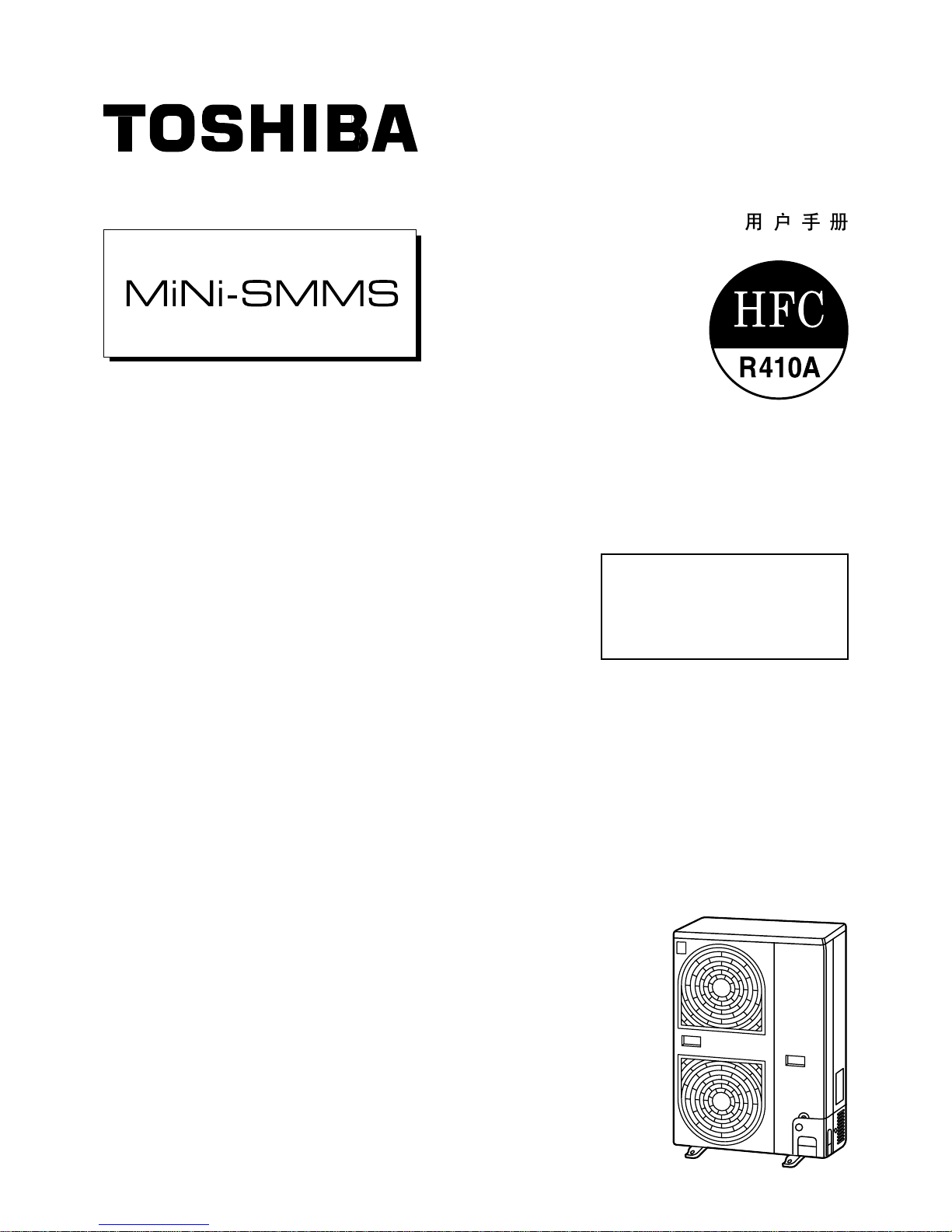
Toshiba MMU-AP0151MH, MMU-AP0091MH, MMU-AP0121H, MMU-AP0151H, MMU-AP0181H Owner's Manual
...
OWNERS MANUAL
MANUEL DU PROPRIETAIRE
BETRIEBSANLEITUNG
MANUALE DEL PROPRIETARIO
MANUAL DEL PROPIETARIO
MANUAL DO UTILIZADOR
GEBRUIKSAANWIJZING
ПДЗГЙЕУ ЧСЗУЗУ
Indoor Unit
4-way Air Discharge Cassette Type
MMU-AP0071MH, AP0091MH, AP0121MH, AP0151MH, AP0181MH,
MMU-AP0091H, AP0121H, AP0151H, AP0181H, AP0241H,
MMU-AP0271H, AP0301H, AP0361H, AP0481H
2-way Air Discharge Cassette Type
MMU-AP0071WH, AP0091WH, AP0121WH,
MMU-AP0151WH, AP0181WH, AP0241WH,
MMU-AP0271WH, AP0301WH
1-way Air Discharge Cassette Type
MMU-AP0071YH, AP0091YH, AP0121YH,
MMU-AP0152SH, AP0182SH, AP0242SH
Concealed Duct Standard Type
MMD-AP0071BH, AP0091BH, AP0121BH, AP0151BH, AP0181BH,
MMD-AP0241BH, AP0271BH, AP0301BH, AP0361BH, AP0481BH
Slim Duct Type
MMD-AP0071SPH(SH), AP0091SPH(SH), AP0121SPH(SH),
MMD-AP0151SPH(SH), AP0181SPH(SH)
Concealed Duct High Static Pressure Type
MMD-AP0181H, AP0241H, AP0271H, AP0361H, AP0481H
Under Ceiling Type
MMC-AP0151H, AP0181H, AP0241H, AP0271H, AP0361H, AP0481H
High Wall Type
MMK-AP0071H, AP0072H, AP0091H, AP0092H, AP0121H,
MMK-AP0122H, AP0151H, AP0181H, AP0241H
Floor Standing Cabinet Type
MML-AP0071H, AP0091H, AP0121H,
MML-AP0151H, AP0181H, AP0241H
Floor Standing Concealed Type
MML-AP0071BH, AP0091BH, AP0121BH,
MML-AP0151BH, AP0181BH, AP0241BH
Floor Standing Type
MMF-AP0151H, AP0181H, AP0241H,
MMF-AP0271H, AP0361H, AP0481H
Outdoor Unit
Heat Pump Model
MCY-MAP0401HT, HT2D,
MCY-MAP0501HT, HT2D,
MCY-MAP0601HT, HT2D
ADOPTION OF NEW REFRIGERANT
This Air Conditioner is a new type which adopts a new
refrigerant HFC (R410A) instead of the conventional
refrigerant R22 in order to prevent destruction of the
ozone layer.
UTILISATION DU NOUVEAU REFRIGERANT
Ce climatiseur est d’un type inédit qui utilise le nouveau
réfrigérant HFC (R410A) au lieu du réfrigérant
traditionnel R22, afin d’éviter la destruction de la couche
d’ozone.
EINFÜHRUNG EINES NEUEN KÜHLMITTELS
Dies ist ein neuartiges Klimagerät. Anstatt des
herkömmlichen Kühlmittels R22 verwendet es das neue
ozonschicht-schonende HFC Kühlmittel R410A.
ADOZIONE DI UN NUOVO REFRIGERANTE
Questo condizionatore d'aria è di un tipo nuovo che
adotta un nuovo refrigerate HFC (R410A) al posto del
refrigerante convenzionale R22, per prevenire la
distruzione dello strato di ozono dell'atmosfera terrestre.
ADOPCIÓN DE NUEVO REFRIGERANTE
Este aparato de aire acondicionado es un modelo
reciente que incorpora el nuevo refrigerante HFC
(R410A) en lugar del refrigerante convencional R22
para así evitar daños en la capa de ozono.
ADOPÇÃO DO NOVO REFRIGERANTE
Este ar condicionado é um modelo novo que adopta um
novo refrigerante HFC (R410A) em vez do refrigerante
convencional R22 para evitar a destruição da cama de
ozono.
ХЙПИЕФЗУЗ НЕПХ ШХКФЙКПХ
Фп рбсьн Клймбфйуфйкь еЯнбй нЭпт фэрпт рпх хйпиефеЯ нЭп
шхкфйкь HFC (R410A) уфз иЭуз фпх ухмвбфйкпэ
шхкфйкпэ R22 рспкеймЭнпх нб впзиЮуей уфзн рспуфбуЯб
фпх ьжпнфпт.
TOEPASSING V AN EEN NIEUW KOELMIDDEL
Deze airconditioner is een nieuwe type dat werkt met
een nieuw koelmiddel HFC (R410A) in plaats van met
het conventionele koelmiddel R22, als bijdrage om de
aantasting van de ozonlaag te reduceren.
Thank you very much for purchasing TOSHIBA Air Conditioner.
Please read this owner's manual carefully before using your Air
Conditioner.
• Be sure to obtain the “Owner’s manual” and “Installation manual” from
constructor (or dealer).
Request to constructor or dealer
Please clearly explain the contents of the Owner’s manual and hand over it.
Nous vous remercions pour avoir choisi un climatiseur TOSHIBA.
Veuillez lire attentivement ce Manuel du propriétaire avant d’utiliser votre
climatiseur.
• Assurez-vous que le constructeur (ou le revendeur) vous remette le
“Manuel du propriétaire” et le “Manuel d’installation”.
Demande au constructeur ou au revendeur
Veuillez expliquer clairement le contenu du Manuel du propriétaire et le
remettre au client.
Wir danken Ihnen, dass Sie sich für ein TOSHIBA Klimagerät entschieden
haben.
Bitte lesen Sie diese Betriebsanleitung, bevor Sie Ihr Klimagerät benutzen, sorgfältig.
• Lassen Sie sich die “Betriebsanleitung” und das “Installations-Handbuch”
unbedingt vom Installateur oder vom Lieferanten aushändigen.
Eine Bitte an den Installateur oder Lieferanten:
Bitte erklären Sie dem Käufer den Inhalt der Betriebsanleitung und händigen
sie ihm aus.
Grazie di aver acquistato un condizionatore d'aria TOSHIBA.
Prima di usare il condizionatore d'aria, leggere con attenzione questo
manuale del proprietario.
• Si raccomanda di tenere a portata di mano il “Manuale del proprietario”
e il “Manuale di installazione” ricevuti dal produttore (o dal rivenditore).
Richiesta al produttore o al rivenditore
Spiegare chiaramente il contenuto del Manuale del proprietario e
consegnarne una copia all'utente.
Muchas gracias por haber adquirido el aparato de aire acondicionado TOSHIBA.
Lea atentamente este manual del propietario antes de utilizar el aparato de aire
acondicionado.
• Asegúrese de que el fabricante (o distribuidor) le proporcione el “Manual del
propietario” y el “Manual de instalación”.
Solicitud al fabricante o distribuidor
Explique con claridad el contenido del Manual del propietario y entréguelo al
cliente.
Muito obrigada por adquirir o Ar Condicionado TOSHIBA.
Leia atentamente este manual do utilizador antes de utilizar o seu ar
condicionado.
• Não se esqueça de receber o “Manual do utilizador” e o “Manual de
inslatação” do fabricante (ou agente).
Pedido ao fabricante ou agente
Explique por favor o conteúdo do Manual do utilizador e entregue-o.
Hartelijk dank voor uw keuze voor een airconditioner van TOSHIBA.
Lees deze gebruiksaanwijzing zorgvuldig door voordat u de
airconditioner gaat gebruiken.
• Zorg ervoor dat u zowel de ‘gebruiksaanwijzing’ als de
‘installatiehandleiding’ van de installateur (of leverancier) krijgt.
Verzoek aan de installateur of de leverancier
Leg de inhoud van de gebruiksaanwijzing duidelijk uit en overhandig de
gebruiksaanwijzing nadien aan de klant.
Убт ехчбсйуфпэме рплэ рпх рспфймЮубфе гйб фзн бгпсЬ убт Энб
Клймбфйуфйкь TOSHIBA.
Рбсбкблпэме дйбвЬуфе рспуечфйкЬ фйт пдзгЯет чсЮузт рсйн брь фз чсЮуз
фпх Клймбфйуфйкпэ.
ВевбйщиеЯфе ьфй п кбфбукехбуфЮт (Ю п рщлзфЮт) убт рбсЭдщуе кбй фйт
ПдзгЯет ЧсЮузт кбй фп ЕгчейсЯдйп ЕгкбфЬуфбузт.
РбсЬклзуз гйб фпн кбфбукехбуфЮ Ю фпн рщлзфЮ
Рбсбкблю еозгЮуфе ме убцЮнейб фб ресйечьменб фщн Пдзгйюн ЧсЮузт кбй
рбсбдюуфе фп.
HFC
R410A R22
ITALIANO
ESPAÑOLPORTUGUÊSЕЛЛЗНЙКБ FRANCAISDEUTSCHNEDERLANDS ENGLISH
CONTENTS
SOMMAIRE
INHALT
INDICE
CONTENIDO
ÍNDICE
РЕСЙЕЧПМЕНБ
INHOUD
PRECAUTIONS FOR SAFETY .............................................................1
NAME OF EACH PART .........................................................................3
PARTS NAME OF REMOTE CONTROLLER ........................................ 6
CORRECT USAGE................................................................................8
ADJUSTMENT OF WIND DIRECTION.................................................. 9
TIMER OPERATION ............................................................................ 16
INSTALLATION....................................................................................17
MAINTENANCE...................................................................................18
AIR CONDITIONER OPERATIONS AND PERFORMANCE ............... 2 2
RE-INSTALLATION ............................................................................. 23
WHEN THE FOLLOWING SYMPTOMS ARE FOUND ........................ 24
MESURES DE SECURITE .................................................................. 26
NOM DE CHAQUE PIÈCE................................................................... 28
NOM DES PIECES DE LA TELECOMMANDE ................................... 31
UTILISATION CORRECTE ..................................................................33
REGLAGE DU SENS DE SOUFFLAGE .............................................. 34
FONCTIONNEMENT PAR MINUTERIE .............................................. 41
INSTALLATION....................................................................................42
ENTRETIEN......................................................................................... 43
FONCTIONNEMENT ET PERFORMANCES DU CLIMATISEUR ....... 47
REINSTALLATION...............................................................................48
EN PRÉSENCE DES SYMPTÔMES SUIVANTS ................................ 49
SICHERHEITSVORKEHRUNGEN ...................................................... 51
BEZEICHNUNGEN DER TEILE .......................................................... 53
TEILEBEZEICHNUNG DER FERNBEDIENUNG ................................ 56
RICHTIGE HANDHABUNG .................................................................58
EINSTELLUNG DES LUFTSTROMS ..................................................59
ZEITBETRIEB......................................................................................66
INSTALLATION....................................................................................67
WARTUNG ...........................................................................................68
FUNKTIONEN UND LEISTUNG DES KLIMAGERÄTS ......................72
NEU-INSTALLATION........................................................................... 73
VORGEHENSWEISE BEI FOLGENDEN SYMPTOMEN ....................74
PRECAUZIONI PER LA SICUREZZA................................................. 76
NOME DI OGNI PARTE ....................................................................... 78
NOME DELLE PARTI DEL TELECOMANDO .....................................81
USO CORRETTO ................................................................................ 83
REGOLAZIONE DELLA DIREZIONE DELL’ARIA.............................. 84
FUNZIONAMENTO CON TIMER ......................................................... 91
INSTALLAZIONE .................................................................................92
MANUTENZIONE ................................................................................ 93
OPERAZIONI E PRESTAZIONI DEL CONDIZIONATORE D’ARIA....97
RE-INSTALLAZIONE ........................................................................... 98
QUANDO SI RISCONTRANO I SINTOMI SEGUENTI ........................ 99
PRECAUCIONES PARA SU SEGURIDAD .......................................101
NOMBRE DE CADA COMPONENTE ............................................... 103
DESCRIPCIÓN DE LOS BOTONES DEL CONTROL REMOTO ......106
UTILIZACIÓN CORRECTA................................................................108
AJUSTE DE LA DIRECCIÓN DEL AIRE .......................................... 109
FUNCIONAMIENTO DEL TEMPORIZADOR.....................................116
INSTALACIÓN ................................................................................... 117
MANTENIMIENTO ............................................................................. 118
FUNCIONES Y RENDIMIENTO DEL APARATO DE AIRE
ACONDICIONADO ............................................................................122
REINSTALACIÓN .............................................................................. 123
CUANDO SE DETECTAN LOS SIGUIENTES SÍNTOMAS...............124
PRECAUÇÕES DE SEGURANÇA.................................................... 126
NOMES DE CADA PEÇA..................................................................128
NOME DAS PEÇAS DO CONTROLADOR REMOTO.......................131
UTILIZAÇÃO CORRECTA ................................................................133
REGULAÇÃO DA DIRECÇÃO DO VENTO.......................................134
OPERAÇÃO DO TEMPORIZADOR .................................................. 141
INSTALAÇÃO .................................................................................... 142
MANUTENÇÃO ................................................................................. 143
FUNCIONAMENTO E PERFORMANCE DO APARELHO DE AR
CONDICIONADO...............................................................................147
REINSTALAÇÃO ............................................................................... 148
SE FOREM DETECTADOS OS SEGUINTES SINTOMAS ............... 149
VOORZORGSMAA TREGELEN V OOR UW VEILIGHEID ................. 151
BENAMINGEN VAN DE ONDERDELEN...........................................153
BENAMING VAN DE ONDERDELEN VAN DE
AFSTANDSBEDIENING .................................................................... 156
CORRECT GEBRUIK ........................................................................ 158
INSTELLEN VAN DE LUCHTSTROOMRICHTING ...........................159
DE TIMER GEBRUIKEN.................................................................... 166
INSTALLEREN .................................................................................. 167
ONDERHOUD....................................................................................168
BEDIENING EN WERKING VAN DE AIRCONDITIONER .................172
OPNIEUW INSTALLEREN ................................................................173
WANNEER DE VOLGENDE SYMPTOMEN AANWEZIG ZIJN ......... 174
РСПЦХЛБОЕЙУ ГЙБ БУЦБЛЕЙБ ....................................................... 176
ПНПМБУЙБ ФПХ КБИЕ ЕОБСФЗМБФПУ ........................................ 178
ПНПМБУЙБ ФМЗМБФЩН ФПХ ФЗЛЕЧЕЙСЙУФЗСЙПХ ...................... 181
ПСИЗ ЧСЗУЗ ..................................................................................... 183
СХИМЙУЗ ФЗУ КБФЕХИХНУЗУ ФПХ БНЕМПХ .............................. 184
ЛЕЙФПХСГЙБ ЧСПНПДЙБКПРФЗ ...................................................... 191
ЕГКБФБУФБУЗ .................................................................................. 192
УХНФЗСЗУЗ ....................................................................................... 193
ЛЕЙФПХСГЙЕУ КБЙ БРПДПУЗ ФПХ КЛЙМБФЙУФЙКПХ .................... 1 97
ЕГКБФБУФБУЗ ЕК НЕПХ ................................................................. 198
ПФБН РБСБФЗСЗИПХН ФБ РБСБКБФЩ УХМРФЩМБФБ ........... 199
1
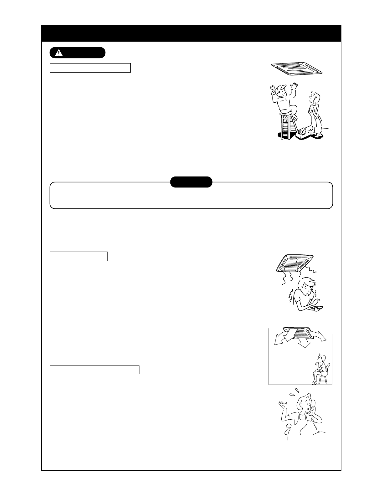
SAFETY PRECAUTIONS
WARNING
Warning on installation
Ensure the unit is installed by qualified personnel.
Specialist knowledge and technology is required to install the unit.
Do not perform the installation by yourself. If an incomplete installation is per-
formed, a fire, electric shock, injury, or water leakage may be caused.
For products that are sold separately, ensure they meet the Toshiba
specification.
For products sold separately, be sure to use those specified by Toshiba.
Otherwise, a fire, electric shock or water leakage ma y occur. For installation
work, leave it to special engineer.
When installing the unit inside a small room, take precautions so that the
refrigerant will not exceed the critical concentration if a leak occurs.
Warning on use
Do not expose your body directly to excessive cool air for long
periods of time.
May effect your physical condition, causing possible health problems.
Never insert a finger or another object into the air inlet port or the air
outlet port of the air conditioner.
Since the fan rotates at a high speed inside the unit, a possible injury may be
caused.
If a fault/error (burnt smell, etc.) occurs, stop the operation, turn off
the power switch and contact the dealer who you
purchased the air conditioner from.
If the unit is allowed to keep running, a fire or electric shock could occur.
Warning on moving/repair
Do not modify the air conditioner in anyway.
As a fire or electric shock may occur.
If the unit requires maintenance or repair, contact the dealer who you
purchased the air conditioner from.
If an incomplete repair is performed, a fire or electric shock may be caused.
When moving or re-installing the air conditioner, contact the dealer
who you purchased the air conditioner from or contact a suitable
engineer.
If an incomplete installation is performed, a fire, electric shock, injury or water
leakage may occur.
CAUTION
Ensure that the unit is installed correctly by a trained engineer . If the unit is incorrectly installed, refrigerant
may leak causing possible oxygen deficiency.
Ensure that the unit is earthed correctly.
The unit must be earthed correctly , if not an electric shoc k may occur. (for details conform to your local building regulations)
2
CAUTION
Caution on installation
Ensure that the drain pipe is installed so that the water can run
freely and without leakage.
If the piping is fitted incorrectly, water may drip , causing possible damage to
furniture, carpets etc.
Check the earth leakage breaker is installed.
It is necessary to attach an earth leakage breaker. Otherwise, you have no
protection against a possible electric shock.
Check the air conditioner is installed in a place where flammable
gases will not leak.
If gas leaks and accumulates in the unit surroundings, an outbreak of fire
may be caused.
Check the outdoor unit is fixed securely to the base.
If it is not fixed securely to the base, the unit may become unstable and fall,
causing possible injury.
Check fixing method
Do not clean the air conditioner with water.
An electric shock may be caused.
Ensure items that are combustible are not placed in the direction
where the air conditioner will flow directly.
Imperfect combustion of the combustible items may occur.
If there are combustible items within the room, ensure that the
room has adequate ventilation, while the air conditioner is in
operation.
If ventilation is inadequate a shortage of oxygen may occur.
Check that the installation plate, etc. is not damaged by long
term use of the air conditioner.
If the installation location deteriorates sufficiently, then the unit may become
unstable and fall, resulting in possib le injury.
Do not put either plants or animals in a location, where the air
conditioner flows air directly.
An adverse eff ect may occur, resulting in possible damage or injury to the
plant/animal.
Do not locate or spray flammable gases etc. near or directly at the
air conditioner.
A fire may be caused.
Do not put vessels containing water such as a vase on the unit.
Moisture may enter the unit, causing a deterioration of the units electrical
isolation properties, causing a possible electric shock.
Do not handle the switches with wet hands.
An electric shock may be caused.
Do not use the air conditioner for special purpose such as storage of foods, plants and animals, precise equipment and art
works.
Deterioration or damage to the goods may occur .
ENGLISH
3
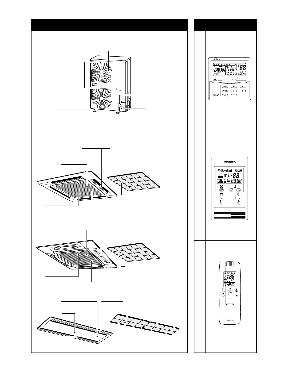
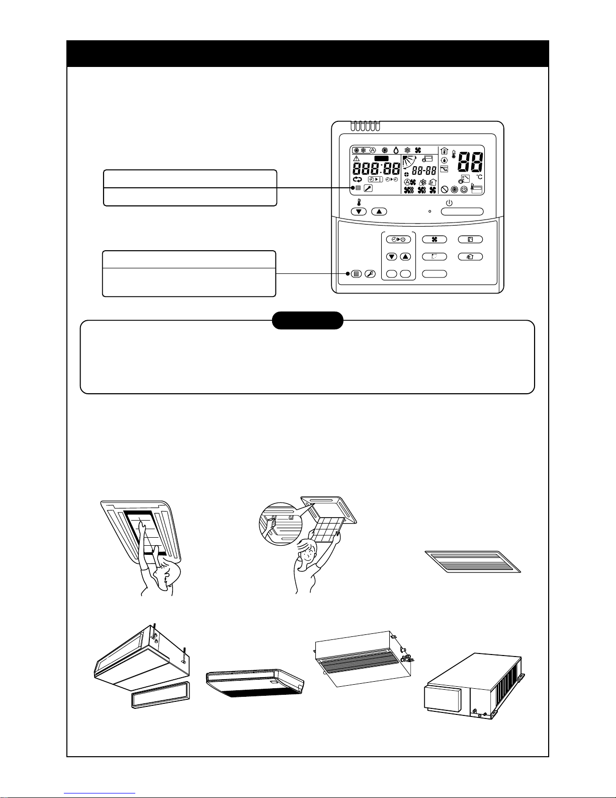
2-way discharge/3-way discharge
2-way discharge or 3-way discharge can be
selected according to the shape or
arrangement of the room.
For details, consult with the dealer which you
have purchased the air conditioner.
Air outlet/Air outlet flap
Select air blow direction in cooling or
heating operation each.
Earth screw
It is included in the electric
parts box.
Air outlet/Air outlet flap
Select air blow direction in cooling or
heating operation each.
Air filter
Removes dust and trash.
(Air filter is provided in the air grille.)
Air inlet grille
Air in the room is sucked from here.
Clip
The clip is to open/close the
air inlet grille.
Air inlet
Air in the room is
sucked from here.
Air filter
Removes dust and trash.
(Air filter is provided in the center panel.)
Earth screw
It is included in the electric parts box.
Center panel
Air outlet/Air outlet flap
Select air blow direction in cooling or
heating operation each.
Indoor unit
[4-way Air Discharge Cassette Type]
MMU-AP0091H, AP0121H, AP0151H, AP0181H, AP0241H,
MMU-AP0271H, AP0301H, AP0361H, AP0481H, AP0561H
[2-way Air Discharge Cassette Type]
MMU-AP0071MH, AP0091MH, AP0121MH, AP0151MH, AP0181MH
Air inlet
They are provided at front,
rear, left, and right sides.
Fixing leg
Air outlet (Discharge)
Hot air is discharged when cooling operation is performed.
Cold air is discharged when heating operation is performed.
Power source hole
Refrigerant pipe
connecting hole
Connecting valve is
included inside here.
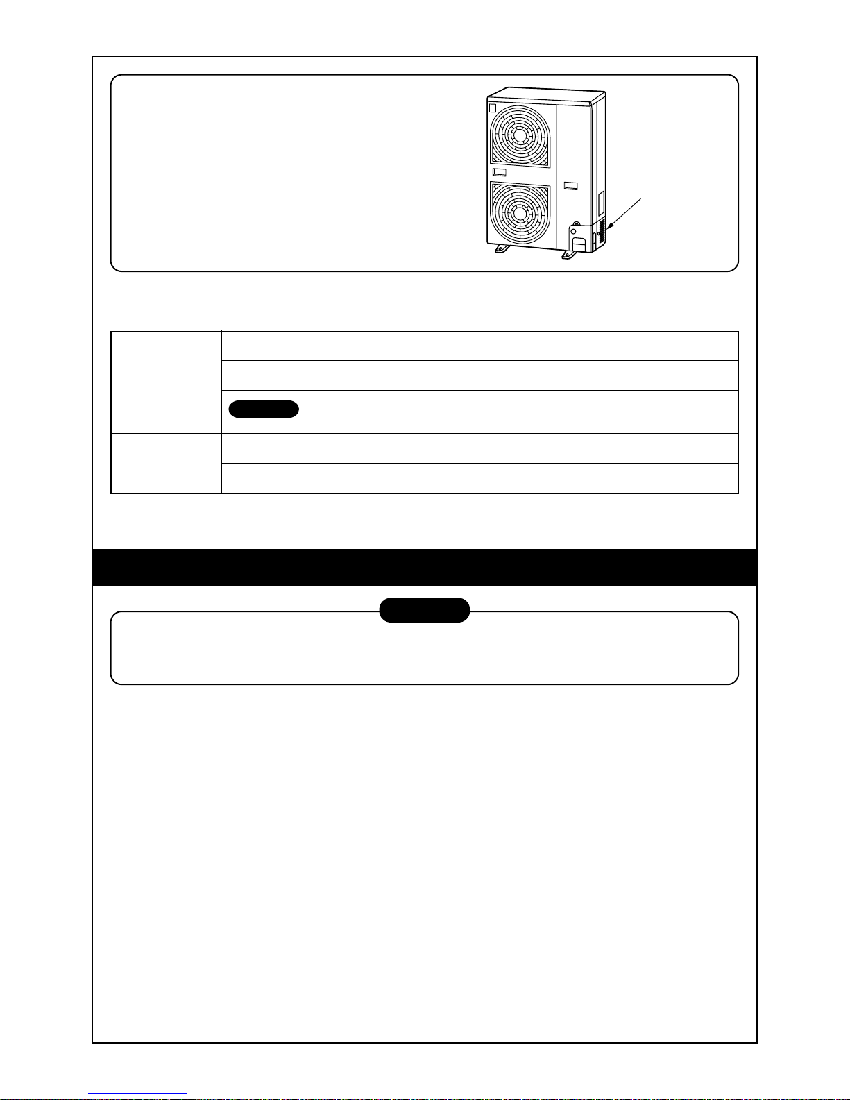
Outdoor unit
Air filter
Removes dust and trash.
(Air filter is provided in the air grille.)
Air inlet grille
Air in the room is sucked from here.
Clip
The clip is to open/close the
air inlet grille.
Earth screw
It is included in the electric
parts box.
ON / OFF
FAN
TEMP.
SWING/FIXTIME
MODE
VENT
UNITSET CL
FILTER
RESET
TEST
TIMER SET
CODE No.
UNIT No.
TEST
SETTING
DATA
SET
R.C. No.
H
˚C
TEST
SETTING
NAME OF EACH PART Sold Separately Pa rts
Wired remote controller
RBC-AMT31E
Simple wired remote controller
RBC-AS21E2
Wireless remote controller kit
TCB-AX21E2 RBC-AX22CE2 RBC-AX21U(W)-E2
4
WEEKLY TIMER
ERROR
SuMoTuWeTh FrSa
PROGRAM1
PROGRAM2
PROGRAM3
SELECT ZONE
CL
SET
GROUP
CODE
No.
UNIT No.
No.
R.C.
TEST
ZONE
ALL
ZONE
GROUP
SETTING
1234
SET DATA
Weekly timer
RBC-EXW21E2
Central remote controller
TCB-SC642TLE2
Earth screw
It is included in the
electric parts box.
Air outlet/
Air outlet flap
Select air blow direction incooling
or heating operation each.
Air inlet grille
Air in the room is sucked from here.
Air filter
Removes dust and trash.
(Air filter is provided in the air inlet grille.)
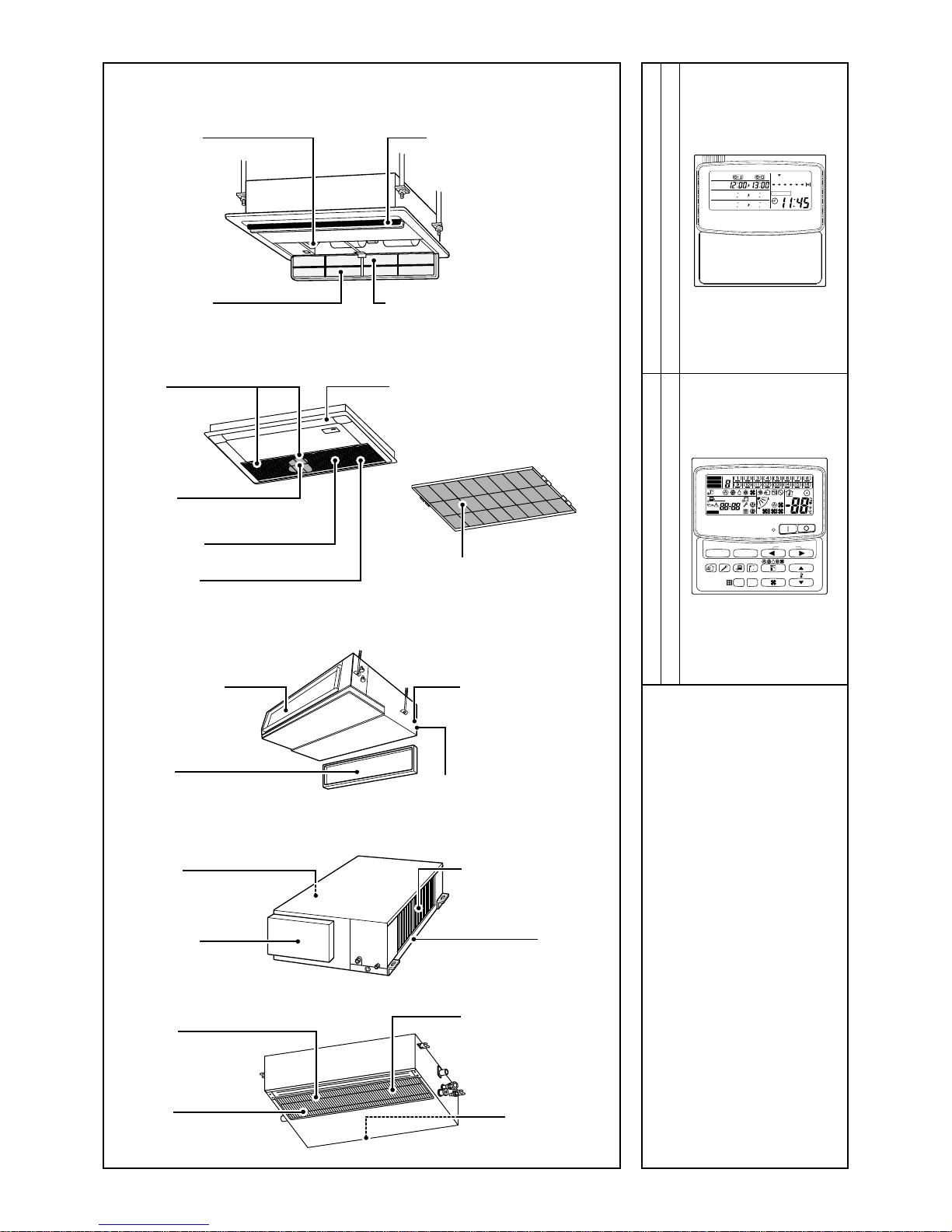
[1-way Air Discharge Cassette Type]
MMU-AP0071YH to AP0121YH
MMU-AP0152SH, AP0182SH, AP0242SH
Button
Button to open/close
suction port
Air outlet/Air outlet flap
Change the direction of the air to be
discharged according to cool/heat mode.
Air filter
Removes dust or trash.
(Provided on the suction port.)
Suction port
Sucks air inside of the room from here.
Earth screw
It is included in the electric parts box.
Air filter
Removes dust or trash.
(Provided on the suction port.)
[Concealed Duct Standard Type]
[Concealed Duct High Static Pressure Type]
[Slim Duct Type]
Air outlet flange
Discharge duct is
connected.
Earth screw
Earth screws are provided
in the electric parts box.
Air filter
Removes dust and trash.
(Air filter is provided in the air inlet grille.)
Air inlet
Air in the room is sucked from here.
Air outlet
Discharge duct is connected.
Air inlet
Suction duct is connected.
Earth screw
Earth screws are provided
in the electric parts box.
Drain pan
Air inlet
Suction duct is connected.
Earth screw
It is included in the electric
parts box.
Air filter
(Air filter is not provided to
some models in the series.)
Air outlet
Discharge duct is
connected.
5
Air outlet/Air outlet flap
Exchanges the air direction according to
cooling or heating time.
Earth screw
It is prepared in the electric parts box.
Air inlet port
Sucks air inside of the room from here.
Air filter
Removes dirt or dust.
(It is included in the suction port.)
Air outlet port
Drain pan (With drain filter)
This accessory is installed at the local site.
Air filter
Removes dirt or dust.
(It is included in the suction port.)
Air inlet port
Sucks air inside of the room from here.
Earth screw
It is prepared in the electric parts box.
Earth screw
It is prepared in the electric parts box.
Front panel (Lower side)
Fixing metal holder
Vertical flap
The air can be automatically discharged
rightward/leftward at stated periods.
Horizontal flap/Air outlet port
Exchanges the air direction according
to cooling or heating time.
Air filter
Removes dirt or dust.
Air inlet port
Sucks air inside of the room from here.
Fixing metal holder (Right and left)
Drain pan
Water accumulated in the drain pan is
drained from here through the drain pipe.
[Under Ceiling Type]
[High Wall T ype]
MMK-AP0071H to AP0241H
MMK-AP0072H to AP0122H
Air inlet grille
Air in the room is sucked from here.
Earth screw
Earth screws are provided in the electric
parts box.
Air filter
Removes dust and trash.
(Air filter is provided in the air inlet grille.)
Air outlet/Air outlet flap
Change the direction of the air to be
discharged according to cool/heat mode.
Button
Button to open/close the suction port
Air filter
Removes dust or trash.
(Provided on the suction port.)
Air inlet port
The air in the room is sucked in from this
port.
Earth screw
Earth screws are provided in the electric
parts box.
Air outlet/Air outlet flap
Change the direction of the air to be discharged according to cool/heat mode.
Air inlet grille
Air in the room is sucked from here.
Earth screw
Earth screws are provided in the electric
parts box.
Air outlet/Air outlet flap
Change the direction of the air to be
discharged according to cool/heat mode.
Air filter
Removes dust and trash.
(Air filter is provided in the air inlet grille.)
[Floor Standing Type]
[Floor Standing Concealed Type]
[Floor Standing Cabinet Type]

6
Display
section
Operation
section
ON / OFF
FAN
TEMP.
SWING/FIXTIME
MODE
VENT
UNITSET CL
FILTER
RESET
TEST
TIMER SET
CODE No.
UNIT No.
TEST
SETTING
DATA
SET
R.C. No.
H
2
15
5
78 9
3
1
4
6
10
11
13
16
12
14
17
CODE No.
UNIT No.
TEST
SETTING
DATA
SET
R.C. No.
H
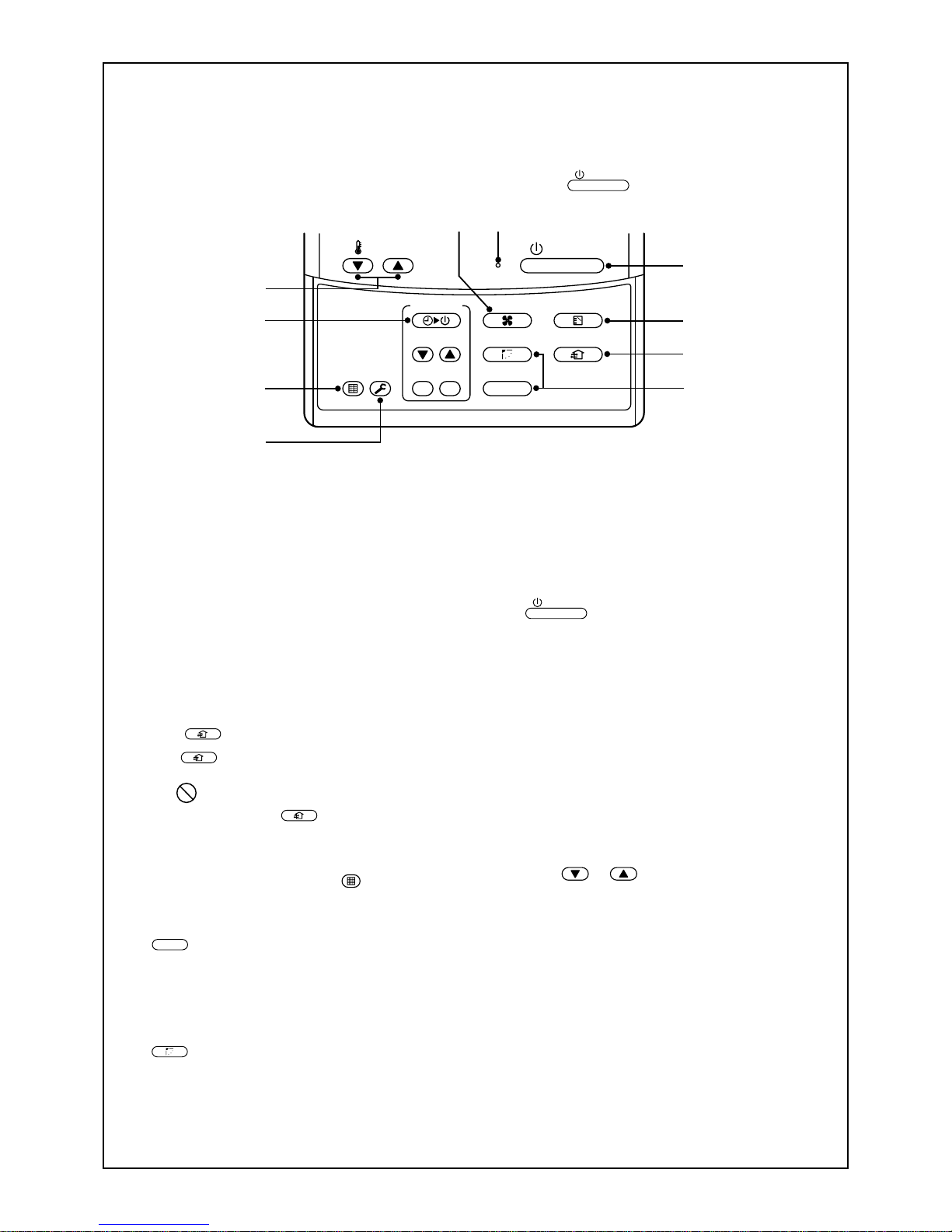
PARTS NAME OF REMOTE CONTROLLER
Display section
In the display example, all indicators are displayed for the explanation.
In reality only, the selected contents are displayed.
• When turning on the leak breaker for the first time, [SET DATA] flashes on
the display part of the remote controller. While this display is flashing, the
model is being automatically confirmed. After the [SET DATA] display has
disappeared, you may use the remote controller.
1
SET DATA displa y
Displayed during the setup of the timer.
2
Operation mode select display
The selected operation mode is displayed.
3
CHECK display
Displayed while the protective device works
or a fault/error occurs.
4
Timer time display
Time on the timer is displayed.
(When a fault/error occurs, the check code is
displayed.)
5
Timer setting setup display
When pushing the Timer setting button, the
display on the timer is selected in order of
[OFF]
→ [OFF] repeat OFF timer
→ [ON]
→ No display.
6
Filter display
If “FILTER ” is displayed, clean the air
filter.
7
TEST run display
Displayed during a test run.
8
Flap position display
(for 4-Wa y Air Dischar ge Cassette Type and
Under Ceiling T ype model only)
Displays flap position.
9
SWING display
Displayed during the up/down movement of the
flap.
10
Set up temperature display
The selected set up temp. is displayed.
11
Remote controller sensor display
Displayed while the sensor on the remote
controller is used.
12
PRE-HEA T displa y
(for Heat-pump model only)
Displayed when the heating operation starts or a
defrost operation is carried out.
While this indication is displayed, the indoor fan
will stop or will go into LOW mode.
13
Operation ready display
Displayed when cooling or heating operation is
impossible because the outdoor temperature goes
out of the operable range.
14
No function display
Displayed if there is no function even when the
button is pushed.
15
Air volume select display
The selected air volume mode is displayed.
(AUTO)
(HIGH)
(MED.) (LOW)
In the Concealed Duct High Static Pressure type
models, [HIGH] only is displayed for the air speed.
16
Mode select control display
Displayed when pushing the “Operation mode
select
” button while the operation mode is
fixed in heating or cooling mode by the system
manager of the air conditioner.
17
Central control display
Displayed when using the remote controller together with a central control remote controller.
If the Remote controller is prohibited at the central
control side,
flashes when operating the
ON / OFF
,
MODE
, / buttons. The change
will not be accepted.
(The contents available to be set up on the remote
controller differ according to the central control
mode. For details, refer to Owner’s Manual of the
central control remote controller.)
7
1
7
3
5
2
8
9
6
4
10
ON / OFF
FAN
TEMP.
SWING/FIXTIME
MODE
VENT
UNITSET CL
FIL TER
RESET
TEST
TIMER SET
Operation section
Push each button to select a desired operation.
This remote controller can operate a maximum of 8 indoor units.
• Before the unit can begin operation, it is firstly necessary to set the units operating parameters. After this
has been completed the air conditioner can be used by pushing the
ON / OFF
button only.
1
Air volume select button
Selects the desired air volume mode.
For the Concealed Duct High Static Pressure
type models this function is unavailable.
2
Timer set button
The TIMER SET button is used when the timer
is set up.
3
Check button
The CHECK button is used to check the units
operation. During normal operation, do not use
this button.
4
Fan
VENT
button
The
VENT
button is used when a fan which is
sold on the market is connected.
• If is displayed on the remote controller
when pushing the
VENT
button, a fan is not
connected.
5
Filter reset button
Resets (Erases) the “FILTER ” display.
6
Air flow direction and Swing function
UNIT
:
If there are multiple indoor units that are controlled by a single remote controller , simply
select each unit in turn for which you wish to
adjust the air flow direction.
SWING/FIX
:
Set up the auto swing and the angle of the flap.
• This function is not provided on the Concealed
Duct Standard Type, High Static Pressure
Type, Floor standing Cabinet Type, Floor
Standing Concealed Type, or Slim Duct Type.
7
Operation lamp
The light will be ON when the unit is in operation and OFF when the unit is not being used.
Note) The light will flash if a protective device
has been operated or if the timer function has
an error.
8
ON / OFF
button
When the button is pushed, the operation
starts. If the button is pressed again, the unit
operation will stop.
When the unit operation has stopped, the
operation lamp and all of the displays will
disappear.
9
Operation select button
Selects the desired operation mode.
10
Set up temperature button
Adjusts the room temperature.
Set the desired set temperature by pushing
the or buttons.
OPTION :
Remote controller sensor
In normal installations the temperature of the room
is sensed by a temperature sensor on the indoor
unit. However it is possible to have the sensor
within your remote controller . For further details
please contact your local dealer .
• In cases where one remote controller controls the
multiple indoor units, the setup operation is
unavailable in group control.
8
1
3
2
4
ON / OFF
FAN
TEMP.
SWING/FIXTIME
MODE
VENT
UNITSET CL
FILTER
RESET
TEST
TIMER SET
HEAT DRY COOL FAN
Heat-pump model
DRY COOL FAN
Cooling only model
(Dehumidity)
LOW MED. HIGH
AUTO
CORRECT USAGE
When you use the air conditioner for the first time or when y ou change the SET DATA value, follow the procedure shown below . For consequent uses the display on the remote controller can be turned on by pushing the
ON / OFF
button only.
Preparation
Turn on the main power supply and/or the leakage breaker.
• When the power supply is turned on, a partition line is shown on the display part of the remote controller.
Note) When the po w er supply is turned on, the remote controller will not accept any operational inputs until
approximately 1 minute has passed. This is not a failure of the unit.
REQUIREMENT
• While using the air conditioner, only operate it with the
ON / OFF
button. Do not turn it off with the main
power switch or the leakage break er.
• Do not turn off the leakage breaker while the air conditioner is in use.
• T urn on the leakage breaker 12 hours or more before the air conditioner is to begin operation or if the
system has not been in use for long periods of time.
1
Push the
ON / OFF
button.
The operation lamp goes on, and the operation will start.
2
Select an operation mode with the
MODE
button.
One push of the button, and the display
changes in the order shown on the right.
•“DRY mode” function is not provided on the
Concealed Duct High Static Pressure Type.
3
Select the air volume with the
FAN
button.
One push of the button, and the display
changes in the order shown on the right.
• When the air volume is set to “AUTO ”, the air volume will differ according to the room temper ature .
• In DRY mode, the “AUTO ” symbol will be displayed and the air volume will be LOW.
• In heating operation, if the room temperature is not heated sufficiently with the air volume set at “LOW
” operation, select the “MED. ” or “HIGH ” operation.
• The temperature sensor for the indoor unit is located near to the air inlet opening and therefore will differ
slightly from the actual room temperature. This difference ma y be increased/decreased depending on the
type of room and its design. (Automatic air speed cannot be selected in F AN mode .)
• The Air Volume function is not provided on the “Concealed Duct High Static Pressure T ype” instead the
air speed “HIGH ” symbol is displayed.
4
Determine the set up temperature by pushing the “TEMP. ” or “TEMP. ” button.
Stop
Push the
ON / OFF
button.
The operation lamp goes off and the unit will stop.

9
REQUIREMENT
[In Cooling operation]
• The operation will start after approximately 1 minute.
[In Heating operation (For Heat-pump model only)]
• In heating operation, the fan operation may continue for approximately 30 seconds after the air conditioner has stopped.
• The indoor fan will continue the preheat operation for 3 to 5 minutes under stop conditions. The indoor
unit will then begin to blow out hot air.
(
symbol on the remote controller display will come on.)
• When the temperature of the room has reached the setup temperature and the outdoor unit stops, the air
speed reduces and so the air volume will decrease.
• In HEA T mode, if the room temperature reaches the set temperature, the outdoor unit will stop and
the air flow / volume will decrease.
• In the defrost mode, the fan will stop so that cool air is not discharged and the PRE-DEF is displayed.
ADJUSTMENT OF WIND DIRECTION
To increase the cooling or heating effect, be sure to use the discharge flap in different directions when in cooling or heating operation.
The characteristics of air are such that cold air will accumulate in the lower half of the room, while hot air will
accumulate in the upper half.
CAUTION
Set the flap horizontally in cooling operation.
If a cooling operation is performed with a downwards discharge, the surf ace of the discharge port or flap
will become wet with dew, and water may drip down.
REQUIREMENT
• If a heating operation is performed with a horizontal discharge, unevenness the room temperature may
not be equal i.e. there may be a large variance between one side of the room with the other.
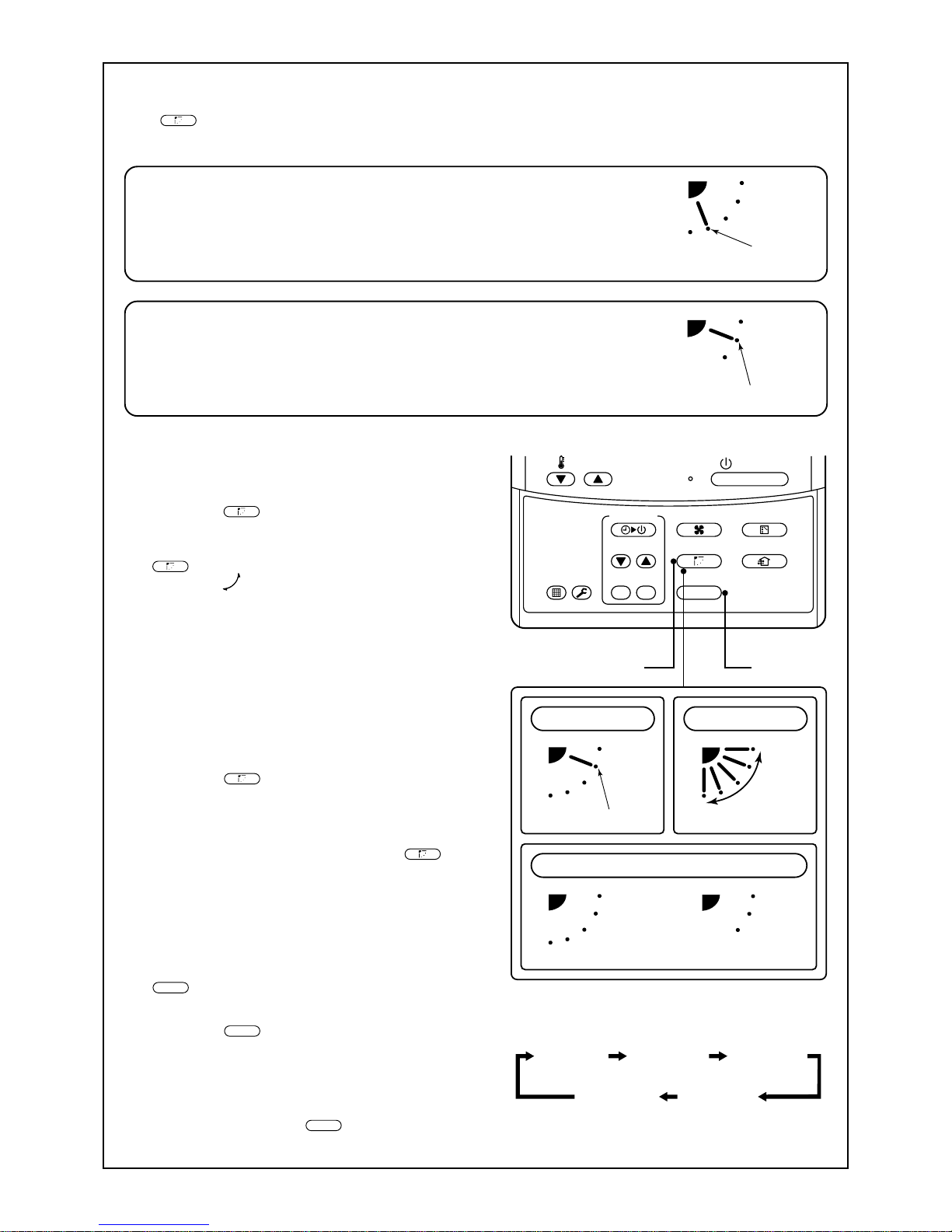
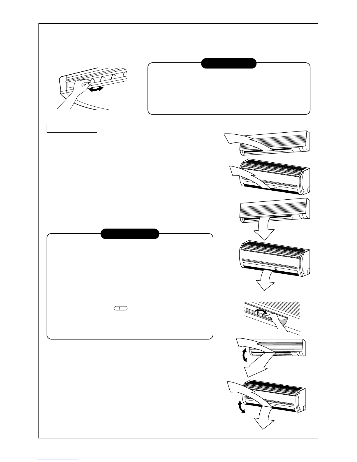
4-way Air Discharge Cassette Type
• When the air conditioner is not in operation, the
discharge flap will automatically directs downwards.
• When the air conditioner is in ready status for heating, the discharge flap will be directed upwards.
The swinging operation will begin after heating
ready status has been cleared. Please note the
“SWING
” symbol will still be displayed on the
remote controller even when the unit status is ready
to begin the heating operation.
[In Cooling operation]
Use the discharge flap with a horizontal set point.
[In Heating operation (For Heat-pump model only)]
Use the discharge flap with a downwards set point.
10
Initial setup
Initial setup
ON / OFF
FAN
TEMP.
SWING/FIXTIME
MODE
VENT
UNITSET CL
FIL TER
RESET
TEST
TIMER SET
In FAN operation
1, 2, 3 4
In all modes
Display when stopping the swing
Initial setup
Series of
operation
Fan/Heat
operation
Cool/Dry
operation
Unit No. 1-1No display Unit No. 1-2
Unit No. 1-4 Unit No. 1-3
How to set up the air direction
Push
SWING/FIX
button.
1
Every pushing the button, the air direction changes.
In Heating operation
Set the air outlet flap downward.
If directing it upward, the hot air may not come to the foot.
How to adjust the the air flow direction,
using the swinging function
2
Push the
SWING/FIX
button.
Set the direction of the air outlet flap to
the lowest position and then push the
SWING/FIX
button again.
• [SWING ] is displayed and the air flow
direction will automatically change either
upwards/downwards.
In the case where one remote controller controls multiple indoor units, each indoor unit can
be selected and its air flow direction can be
adjusted.
How to stop the flap from swinging
3
Push the
SWING/FIX
button again while the
horizontal flap is moving.
• The horizontal flap can be stopped at any
position desired. If you wish to return the flap to
it original upwards position, press the
SWING/FIX
button again.
* During the cooling/drying operation the hori-
zontal flap will not stop at its most downwards
facing position 9 (reduce the risk of water
dripping), but will instead move to the 3rd
position from the top (as shown in the figure).
4
UNIT
• T o set up the air flo w direction individually,
push the
UNIT
button to display each indoor
unit No. in a group control. You can then set the
air flow direction for the displayed indoor unit.
• If there is no display, all the indoor units can be
operated collectively.
• For every push of the
UNIT
button, the display
will alter between units as shown in the figure.
In Cooling / Dry operation
Set the air outlet flap Upwards.
If directing it downwards, the dew may form on the near side of the air discharge
port and could drip.

11
ON / OFF
FAN
TEMP.
SWING/FIXTIME
MODE
VENT
UNITSET CL
FILTER
RESET
TEST
TIMER SET
1, 2 3
Unit No. 1-1No display Unit No. 1-2
Unit No. 1-4 Unit No. 1-3
Based on the shape or arrangement of the room, the cold air and hot air can be discharged in two directions or
three directions. For details, please contact your local dealer.
INFORMATION
• If cooling operation is performed with a downwards discharge, dew may form on the surface of the
cabinet or the horizontal flap resulting in dripping.
• If heating operation is performed with a horizontal discharge, the room temperature may not be equal i.e.
there may be a large variance between one side of the room with the other.
• Do not move the horizontal flap directly with your hands; otherwise a fault maybe caused. Select the
direction of the horizontal flap using the flap operation switch on the remote controller . The horizontal flap
will not stop immediately, even if the switch is pushed.
Note) Pushing the switch again when the required louver direction has been reached will stop the louv er.
2-way Air Discharge Cassette Type
[In Cooling operation]
Use the air outlet flap with a horizontal set point.
[In Heating operation (For Heat-pump model only)]
Use the air outlet flap with a downwards set point.
Setup of air flow direction and swinging function
1
Push the
SWING/FIX
button during operation.
• [SWING ] is displayed and the air flow direction will automatically change either upwards/downwards.
In the case of one remote controller that controls multiple indoor units, each indoor unit can be selected
and its air flow direction can be adjusted.
2
Push the
SWING/FIX
button again during the swinging
of the air outlet flap.
• The air outlet flap will be stopped at the desired position.
3
UNIT
• T o set up the air flo w direction individually, push the
UNIT
button to display each indoor unit No. in a group
control. You can then set the air flow direction for the
displayed indoor unit.
• If there is no display , all the indoor units can be operated collectively.
• For every push of the
UNIT
button, the display alters
between units, as shown in the figure.
1-way Air Discharge Cassette Type
Adjustment of air flow direction upwards/downwards
[In Cooling operation]
In cooling operation, use the air outlet flap with a horizontal set point
so that the cold air diffuses the whole room.
[In Heating operation (For Heat-pump model only)]
In heating operation, use the air outlet flap with a downwards set
point so that the hot air is directed towards the floor.
Adjustment of air flow direction rightwards/leftwards
To change the discharge direction to right or left side, set the ve rtical grille inside of the air outlet flap to the desired direction.
Setup the air flow direction and swinging function
Refer to the description of the “2-w ay Air Discharge Cassette Type”.
12
Initial setup
Initial setup
ON / OFF
FAN
TEMP.
SWING/FIXTIME
MODE
VENT
UNITSET CL
FILTER
RESET
TEST
TIMER SET
In FAN operation
1, 2, 3 4
In all modes
Display when stopping the swing
Initial setup
Series of
operation
Fan/Heat
operation
Cool/Dry
operation
Unit No. 1-1No display Unit No. 1-2
Unit No. 1-4 Unit No. 1-3
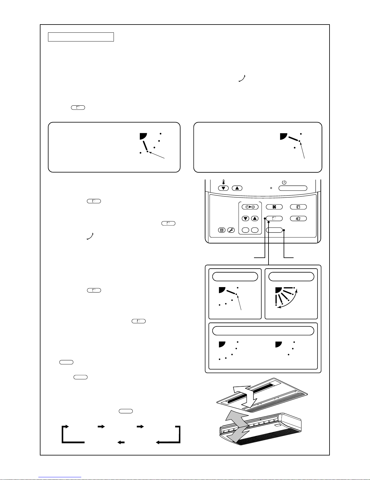
Under Ceiling Type
• While the air conditioner is not in operation, the horizontal flap (Up/Down air direction
adjustment plate) will automatically point upwards.
• When the air conditioner is in ready status for heating, the horizontal flap (Up/Down air
direction adjustment plate) will points upwards. The swinging operation will begin after the
heating ready status has been cleared. Please note the “SWING
” symbol will still be
displayed on the remote controller even when the status is ready to heat.
How to adjust the air flow direction
Push the
SWING/FIX
button during operation.
1
Every time you push the button the air
flow direction will change.
How to adjust the air flow direction, using
the swinging function
2
Push the
SWING/FIX
button.
Set the direction of the horizontal flap (Up/
Down air direction adjustment plate) to its
lowest position and then push the
SWING/FIX
button again.
• [SWING ] is displayed and the air direction will
automatically upwards or downwards.
In cases where one remote controller controls
multiple indoor units, it is possible to set each
indoor unit individually, so that the air flow direction can be altered.
How to stop the louver from swinging
3
Push the
SWING/FIX
button again while the horizontal flap is moving
• The horizontal flap can be stopped at any position
desired. If you wish to return the louvre to it original
upwards position, press the
SWING/FIX
button again.
* During the cooling/drying operation the horizon-
tal flap will not stop at its most downwards
facing position 9 (reduce the risk of water
dripping), but will instead move to the 3rd
position from the top (as shown in the figure).
4
UNIT
• T o set up the air flo w direction individually, push
the
UNIT
button to display each indoor unit No. in
a group control. You can then set the air flow
direction for the displayed indoor unit.
• If there is no display, all the indoor units can be
operated collectively.
• For every push of the
UNIT
button, the display
will alter between units as shown in the figure.
In Cooling / Dry operation
Set the horizontal flap (Up/Down
air direction adjustment plate)
upwards. If directing the air flow
downwards, condensation may
form on the surface of the louver
and may cause water to drip.
In Heating operation
Set the horizontal flap (Up/Down
air direction adjustment plate)
downwards. If the air flow is directed
upwards, the hot air may not reach
the floor, creating an uneven
temperature within the room.
13
Right/Left air direction adjustment
To change the air outlet direction to the right or left side, set the vertical flap located behind the horizontal flap
to the desired direction.
INFORMATION
• If cooling operation is performed with a downwards discharge,
dew may form on surface of the cabinet or the horizontal flap
resulting in possible dripping.
• If heating operation is performed with a horizontal discharge,
the room temperature may not be equal i.e. there may be a
large variance between one side of the room with the other .
High Wall T ype
Adjustment of air flow direction upwards/downwards
[In Cooling operation]
In cooling operation, use the horizontal flap with a horizontal set point
so that the cold air diffuses the whole room.
[In Heating operation (For Heat-pump model only)]
In heating operation, use the horizontal flap with a downwards set
point so that the hot air blows tow ards the floor.
REQUIREMENT
• If cooling operation is performed with the louver set at a downwards position, dew may form on the surface of the cabinet or
the horizontal flap resulting in possible dripping.
• If heating operation is performed with the louver set in a horizontal position, the room temperature may not be equal i.e.
there may be a large variance between one side of the room
with the other.
• Do not move the horizontal flap directly with your hands; otherwise a fault/error may be caused. Select the direction of the
horizontal flap using the
SWING/FIX
button on the remote controller .
The horizontal flap will not stop immediately even if the switch
is pushed.
Note) Pushing the switch again when the required louver direction has been reached will stop the louver .
Adjustment of air flow direction rightwards/leftwards
To change the air outlet direction to the right or left side, set the vertical
flap located behind the horizontal flap to the desired direction.
Setup of air direction and swinging
1H series: Refer to the description of “2-way Air Discharge Cassette
Type”.
2H series: Refer to the description of “Under Ceiling Type, 1-wa y Air
Discharge Cassette Type (2SH Series)”.
14
Floor Standing Cabinet Type
[In Cooling operation]
In cooling operation, set the air outlet flap with a horizontal
set point so that the cold air diffuses the whole room.
[In Heating operation (For Heat-pump model only)]
In heating operation, set the air outlet flap with a downwards
set point so that the hot air blows tow ards the floor.
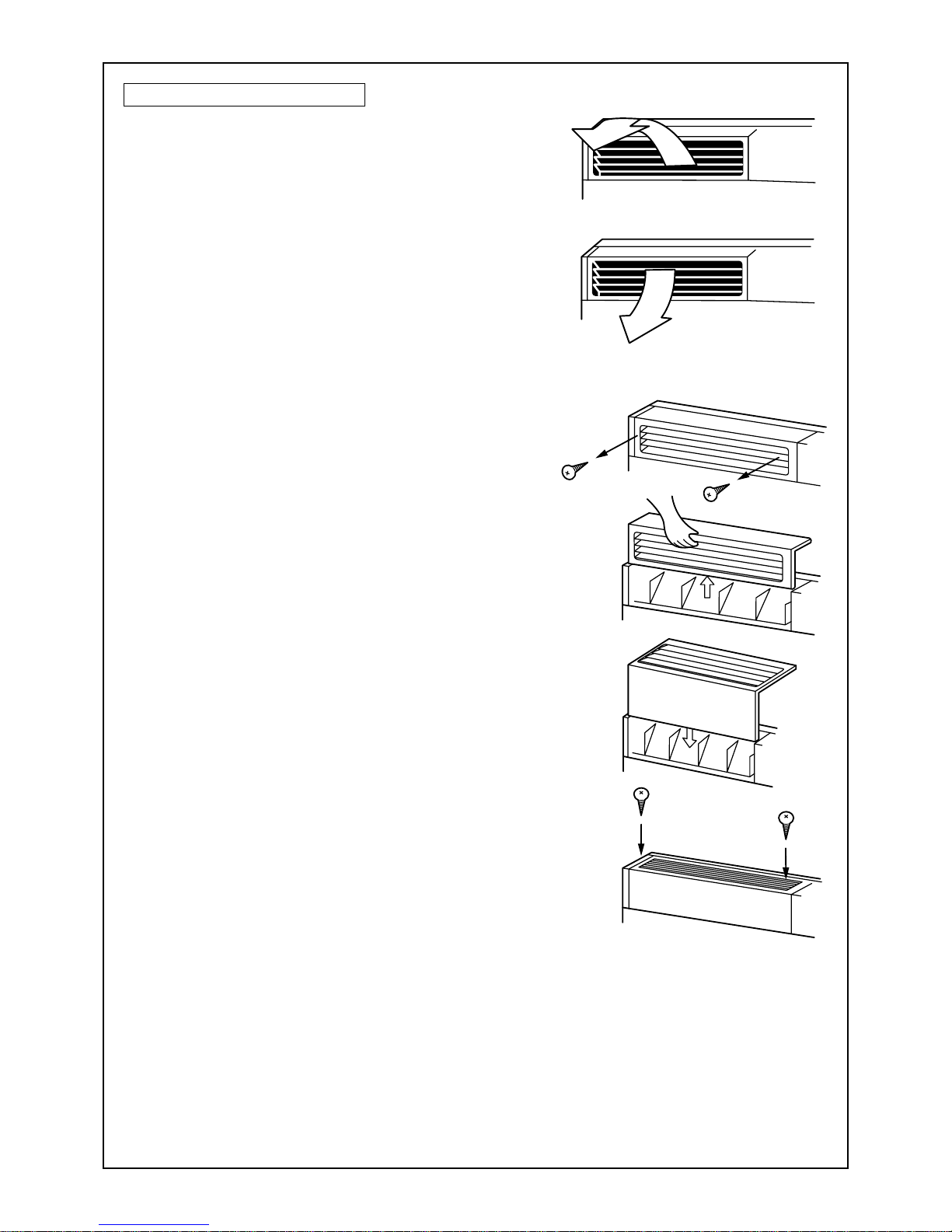
How to change the air outlet port
Change the air outlet port using the following procedure.
1
Remove the two fixing screws on the air outlet
port. (The fixing screws are reused.)
2
Remove the discharge port, by pushing up on
the rear side, to a point where you can remove it
from the rear clip.
3
Lift the air outlet port upwards and remove it.
4
Reverse the air outlet port and attach it to the
main unit.
Pa y attention so that four claw hooks (two at rear and two
at the lower sides) are hooked on the mounting position.
5
Be sure to tighten the air outlet port with the
removed fixing screws so that the air outlet port
does not come off.
15
ON / OFF
FAN
TEMP.
SWING/FIXTIME
MODE
VENT
UNITSET CL
FIL TER
RESET
TEST
TIMER SET
1, 2 3
1
2
In this case, do not use the
swing function.
Unit No. 1-1No display Unit No. 1-2
Unit No. 1-4 Unit No. 1-3
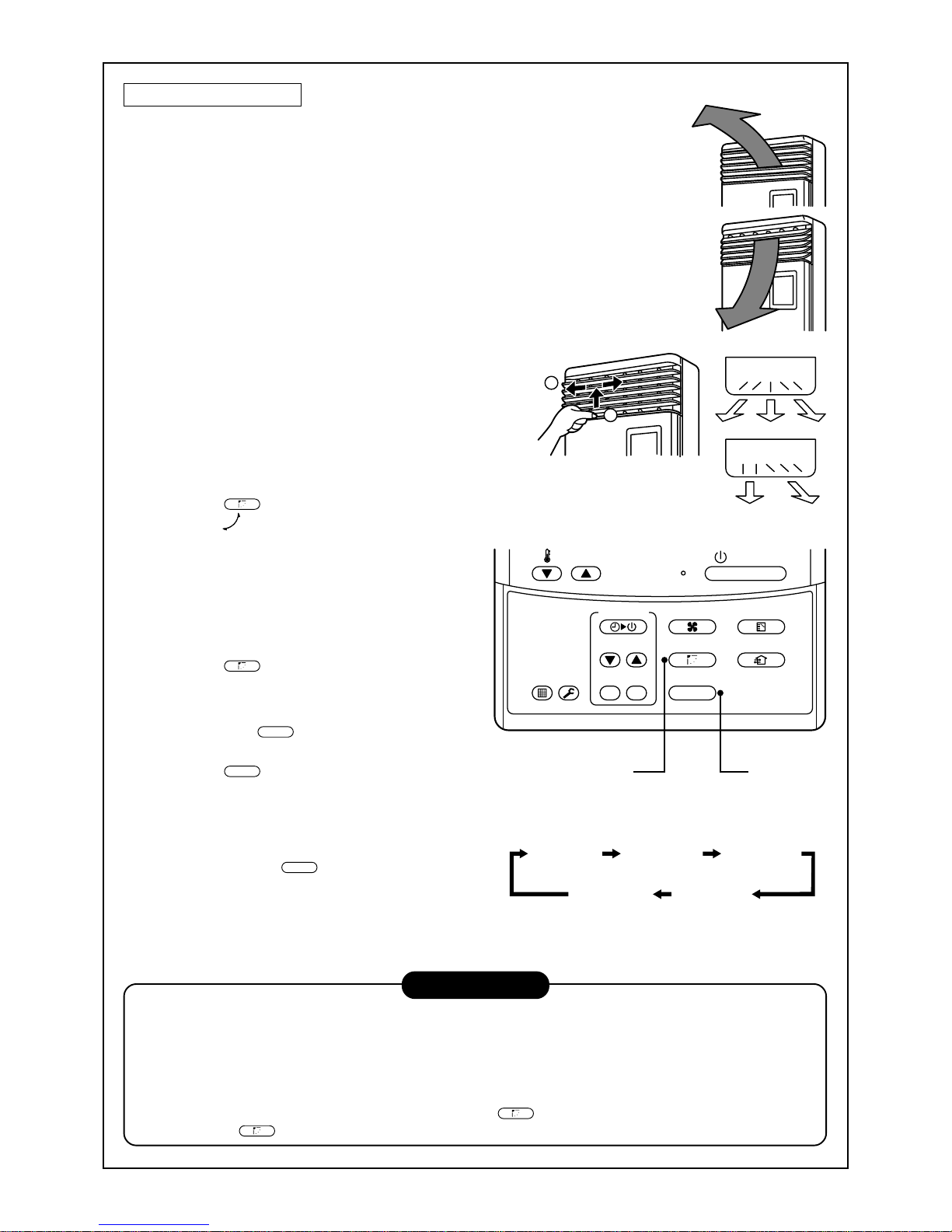
Floor Standing Type
Adjustment of air flow direction upwards/downwards
[In Cooling operation]
In cooling operation, move the flap with your hands so that the horizontal
air outlet points in a direction so that the cold air diffuses the entire room.
[In Heating operation (For Heat-pump model only)]
In heating operation, move the flap with your hands so that the horizontal
air outlet points in a downward direction, towards the floor.
Adjustment of air flow direction rightwards/leftwards
[In case of using unsymmetrical air directions]
Lift up the vertical flap lightly and direct it towards the desired
direction. Once completed lower the flap back down.
In this case, do not use the Swing function.
[In case of automatic swing]
1
Push the
SWING/FIX
button during operation.
• [SWING ] is displayed and the air direc-
tion will automatically change rightwards/
leftwards.
In cases where one remote controller controls multiple indoor units, it is possible to
set each indoor unit individually, so that the
air flow direction can be altered.
2
Push the
SWING/FIX
button again while the
vertical flap is moving will allow you to
stop the louver in the desired position.
3
Swing button
UNIT
• T o set up the air flo w direction individually,
push the
UNIT
button to display each indoor
unit No. in a group control. Then set up the
air flow direction to the desired indoor unit.
• If there is no display, all the indoor units can
be operated collectively.
• Every push of the
UNIT
button, will change
the display as shown in the figure.
INFORMATION
• If cooling operation is performed with downward air outlet, dew may form on the surface of the cabinet or
the horizontal flap, resulting in possible dripping of water.
• If heating operation is performed with the horizontal air outlet actively moving, unevenness of the temperature may increase in the room.
• Do not move the flap directly with your hands during swing operation; otherwise a fault may be caused.
The vertical flap does not stop immediately even if the
SWING/FIX
button is pushed. To adjust the stop posi-
tion, push the
SWING/FIX
button.
16
4
3
2
1
ON / OFF
FAN
TEMP.
SWING/FIXTIME
MODE
VENT
UNITSET CL
FILTER
RESET
TEST
TIMER SET
OFF
(OFF timer) (Repeat OFF timer)
No display
(ON timer)
OFF ON
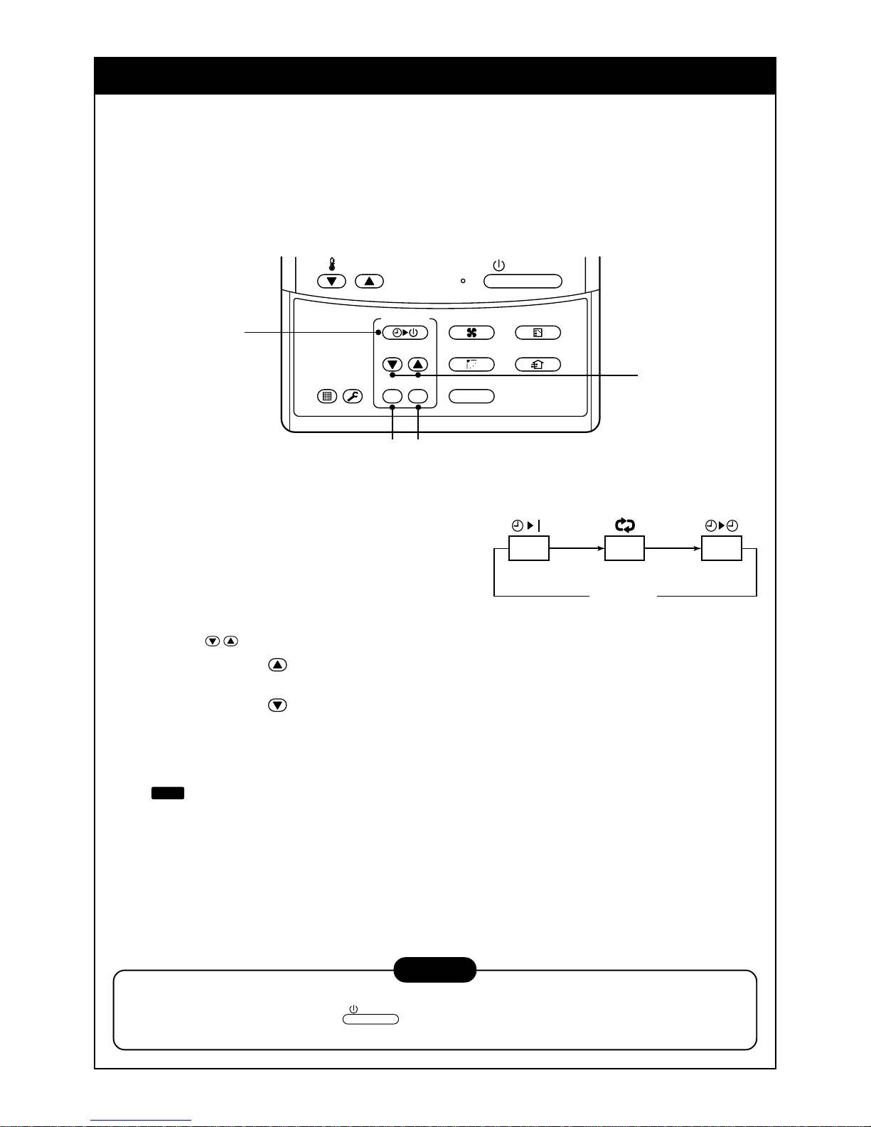
TIMER OPERATION
A type of timer operation can be selected from the following three types.
OFF timer : The operation stops when the time on the timer has reached the set time.
Repeat OFF timer : The unit will stop, every time the set time period has elapsed.
ON timer : The unit will start when the time on the timer has reached the set time.
Timer operation
1
Push the TIMER SET button.
• The timer display (type) changes for every
push of the button.
• SET DATA and timer time displays flash.
2
Push the
TIME
buttons to select the “SET TIME”.
For every push of the button, the set time increases in the unit of 0.5 hr (30 minutes).
The maximum set time is 72.0 hr.
For every push of the button, the set time decreases in the unit of 0.5 hr (30 minutes).
The minimum set time is 0.5 hr.
3
Push the SET button.
•
SETTING
display disappears and timer time display goes on.
When the ON timer is activated, the chosen time period will be displayed. Once the time has been
reached, all displays except the ON light will disappear.
Cancel of timer operation
4
Push the CL button.
• TIMER display will disappear.
NOTICE
• When the unit stops after the timer reached the preset time, the Repeat OFF timer will resume the
operation. However by pushing the
ON / OFF
button the repeat function will stop once the time on the
timer has again reached its set time.
17
INSTALLATION
Installation location
WARNING
• Select a location for installation that will be able to safely support the weight of the unit.
If the installation location is not strong enough to support the unit and the unit falls, injury could result.
CAUTION
• Do not install the unit in a location where combustible gases could conceivably leak.
Leaking gases that accumulate in the vicinity of the unit could be ignited by the unit.
REQUIREMENT
• A location that permits the level installation of the unit
• A location that provides enough space to service the unit safely
• A location where water draining from the unit will not pose a problem
Avoid the following types of locations :
• Locations where salt is present in large amounts (seaside areas), or where sulfuric gases are present in
large amounts (hot springs areas)
(If the unit is to be used in such areas, special maintenance is necessary.)
• Locations that generate oils (including machine oils), steam, oily smoke, or corrosive gases
• Locations where organic solvents are used
• Locations in the vicinity of equipment that generates high frequency signals
• Locations where the outdoor unit will blow in the direction of a neighbor's window
• Locations where the noise of the outdoor unit will pose a problem
• Locations with poor air circulation
Electric wiring
WARNING
Ensure that the unit is correctly earthed.
Grounding is necessary . If earthing is incomplete, an electric shock may be caused.
CAUTION
Check that the circuit breaker is fitted.
Attaching a earth leakage breaker is necessary. Otherwise, an electric shock may be caused.
Make sure that the correct capacity fuses are used.
Using wire or copper wire may cause a fire or unit fault.
Ensure that the power supply to the unit is exclusive and is the correct rated voltage.
To disconnect the appliance from the main power supply.
This appliance must be connected to the main power supply by means a circuit breaker or a switch with a
contact separation of at least 3mm.
18
4-way Air Discharge
Cassette Type
Under Ceiling Type Slim Duct Type
2-way Air Discharge
Cassette Type
Concealed Duct
Standard T ype
1-way Air Discharge
Cassette Type
Concealed Duct
High Static Pressure Type
NO GOOD
NO GOOD
NO GOOD
NO GOOD
NO GOOD
NO GOOD NO GOOD
MAINTENANCE
Cleaning of air filter
• When [FILTER] is displayed on the remote controller, it is time to check and if necessary clean the filter.
• Clogging of air filter decreases the cooling/heating effect.
WARNING
Be sure to turn off the main power supply prior to any maintenance.
• Please do not intend to do the daily maintenance and/or Air Filter cleaning by yourself.
Cleaning the air filter and other parts of the unit involves dangerous work in high places, so be sure to
have a qualified service person do it. Do not attempt it by yourself.
Daily maintenance
• For daily maintenance including Air Filter cleaning, please use qualified service personnel, particularly for the
following models -
4-way Air Discharge Cassette Type Concealed Duct Standard Type Under Ceiling Type
2-way Air Discharge Cassette T ype Slim Duct Type
1-way Air Discharge Cassette Type Concealed Duct High Static Pressure Type
ON / OFF
FAN
TEMP.
SWING/FIXTIME
MODE
VENT
UNITSET CL
FILTER
RESET
TEST
TIMER SET
CODE No.
UNIT No.
TEST
SETTING
DATA
SET
R.C. No.
H
FILTER display
Notifies the time to clean the air filter.
FILTER reset
Push the FILTER switch after cleaning.
“FILTER” display disappears.
19
Push the air filter,
and pull it downward.
Front panel
(Lower)
Air filter knob
Filter holder
High Wall T ype
(Model : 1H series)
• Push the projection at the center of the air filter.
• Undo the clip on the air filter, pull the air filter downwards while
pushing it towards the main unit side.
(Model : 2H series)
• Open the air inlet grille.
Lift the air inlet grille up to the horizontal position.
• T ake hold of the left and right handles of the air filter and lift it up
slightly, then pull downwards to take it out from the filter holder.
Floor Standing Cabinet Type
• Gently push down on the upper part of the suction port, and then
pull towards you to remove it.
• T ake out the air filter inside of the suction port.
Floor Standing Concealed Type
• Push down hook of the air filter on the front panel (Lower side).
• Pull the air filter towards you to remove it.
Floor Standing Type
Removal / Attachment of air filter
• Pull the air filter towards you.
• T o attach the air filter, insert it into the main body and push it in.
NOTE
• When cleaning the air filter, use a small brush or cleaning device. If the air
filter is heavily stained, use a neutral detergent mix ed with warm water.
• After washing the filter, rinse it out thoroughly and place in the shade to
dry . Do not expose to direct sun light.
• Once the air filter has dried, place the air filter back into the unit.
20
Do not use.
Polishing
powder
Benzene
Thinner
Chemical
floor-cloth
Filter holder
Re-installing the air filter
• Insert the the air filter back into the unit, ensuring that both sides of the filter are positioned correctly inside
of the plastic frame.
• Close the air inlet grille.
If the FILTER lamp on the indoor unit is displayed, press the FILTER button on the remote controller or the
TEMPORARY b utton on the indoor unit. This will turn the light off .
Cleaning the air inlet grille
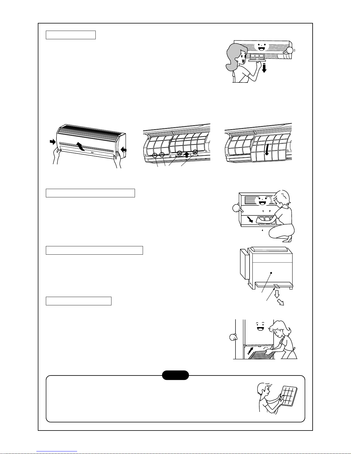
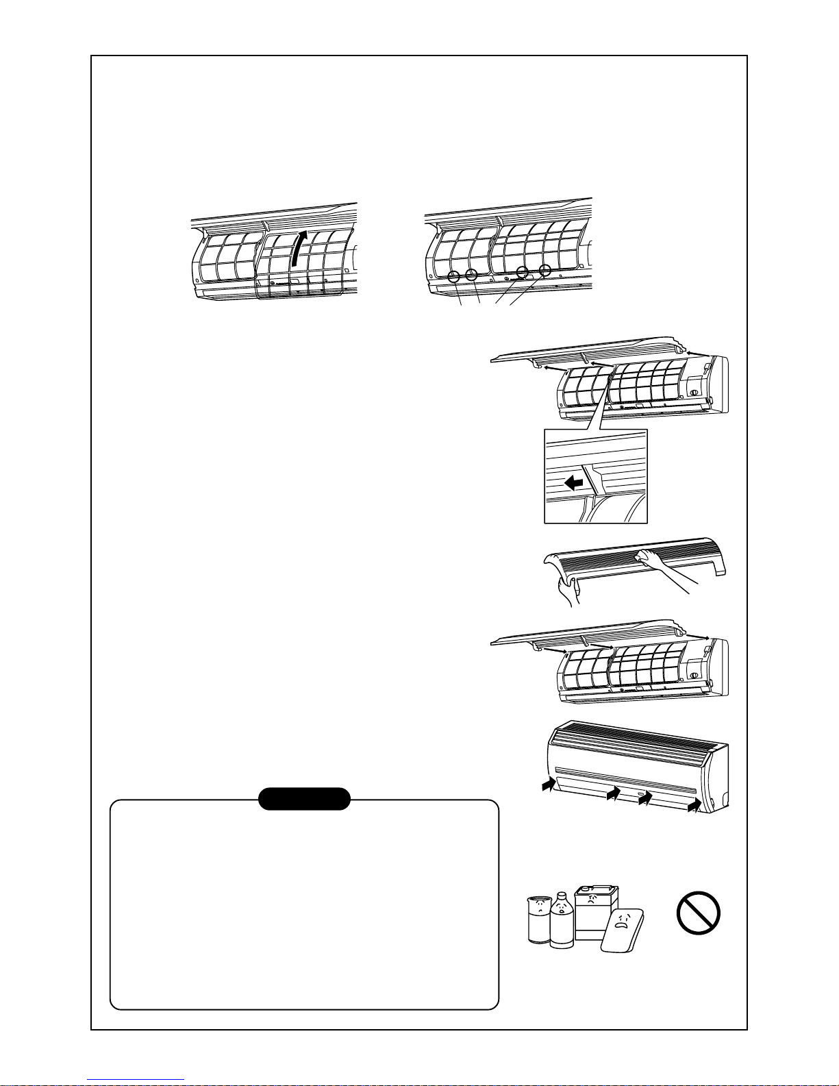
1. Remove the air inlet grille.
Hold the two sides of the air inlet grille and open upwards.
Move the center arm to the left and remove the grille.
2. Wash the grille with water using a soft sponge or towel.
(Do not use metallic scrubbing brush or other hard brushes.)
• Use of such hard objects will cause scratches on the
surface of the grille, and the metal coating to peel off.
• If very dirty, clean the air inlet grille with a neutral detergent
for kitchen use, and rinse off with water.
3. Dry the inlet grille, ensuring no water is left.
4. Fit the left and right arms of the air inlet grille to the shafts on
the two sides of the air conditioner and push in completely.
Then push in the center arm.
5. Chec k that the center arm has been completely inserted and
then close the air inlet grille.
• Push the arrow locations (four) at the bottom of the air inlet
grille to check whether the grill is completely closed.
Cleaning of the main unit / remote controller
CAUTION
• Wipe them with a soft and dry cloth.
• A cloth dampened with cold water may be used on the indoor
unit if it is very dirty.
• Never use a damp cloth on the main unit and the remote
controller.
• Do not use or leave a chemically treated duster on the unit for
long periods of time, as it may damage or alter the colour of the
unit surface.
• Do not use benzine, thinner, polishing powder, or similar solvents for cleaning. These may cause the plastic surface to
crack or deform.
21
I will wipe soft
and dry cloth!
Use after drying
when it has not been
used for a long time!
Control
Gee, chilly
Clean, please.
Please close
Blows upward
Blows downward
Air flow adjustment
Cool and
dry air
Warm
air
If you do not plan to use the unit for more than 1 month
1. Operate the fan for 3 to 4 hours to dry the inside of the unit
• Operate “FAN” mode.
2. Stop the air conditioner and turn off the main power supply
or the circuit breaker .
Checks before operation
1. Check that the air filters are installed.
2. Check that the air outlet or inlet is not blocked.
3. Turn on the main power switch or the circuit breaker f or the
main power supply to the air conditioner .
NOTE
For Air conditioning system which is operated regularly, cleaning and maintenance of the indoor/outdoor
units are strongly recommended.
As a general rule, if an indoor unit is operated for about 8 hours daily, the indoor/outdoor units will need to
be cleaned at least once every 3 months. This cleaning and maintenance shall be carried out by a qualified person.
Failure to clean the indoor/outdoor units regularly will result in poor perf ormance, icing, water leakage and
even compressor failure.
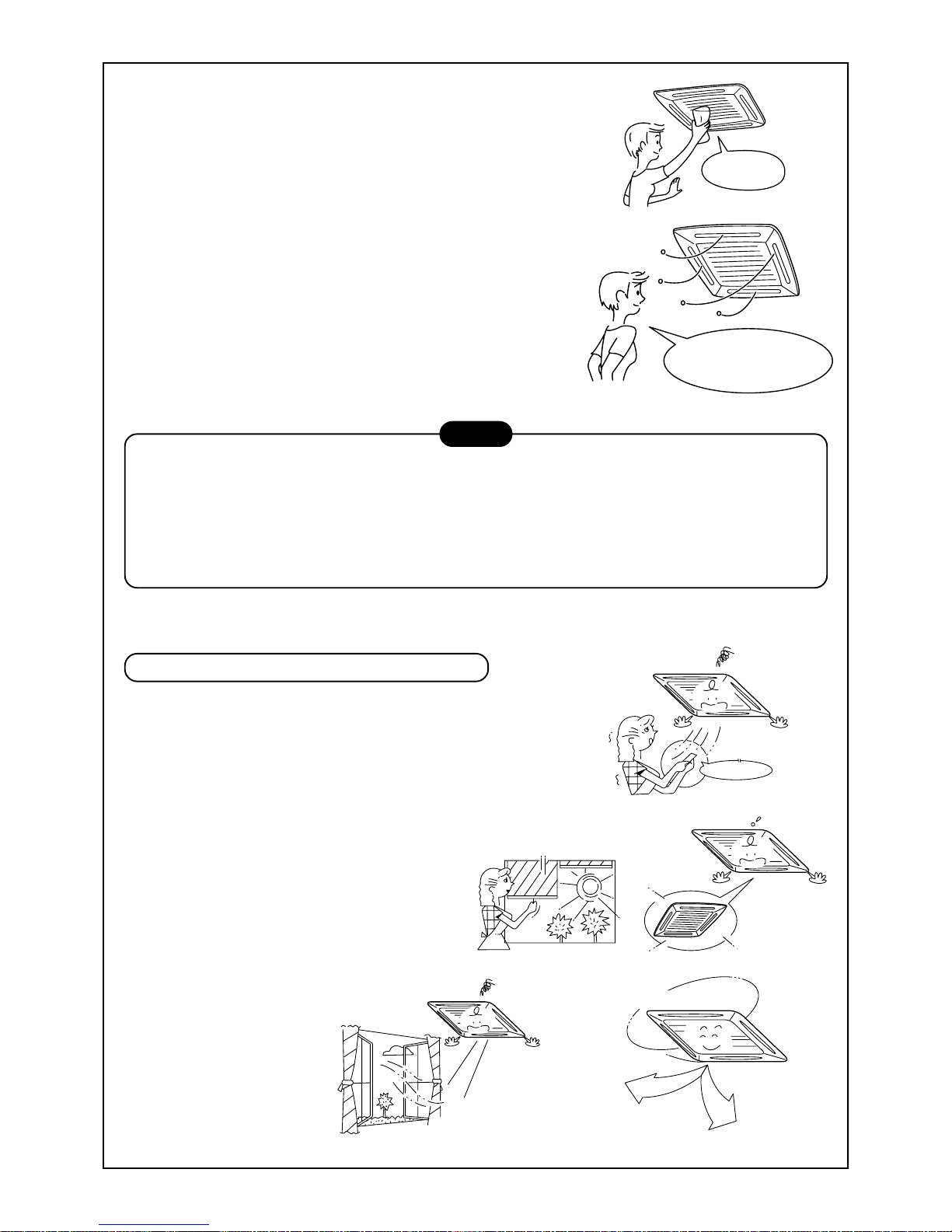
HINTS FOR ECONOMICAL OPERA TION
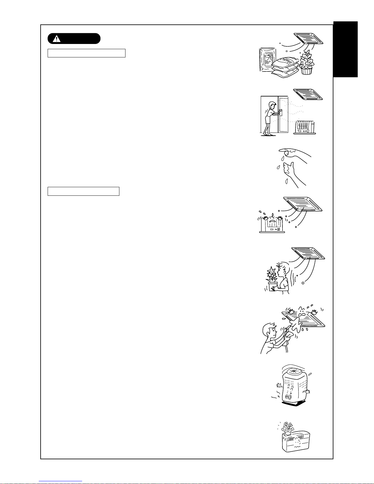
Maintain room temperature at comfortable level
Clean air filters
The clogged air filter impairs the performance of the air conditioner.
Never open doors and windows more than what is necessary
To keep the cool or warm air in the room, nev er open doors and
windows more than what is necessary .
Window curtains
In cooling, close the curtains to avoid direct sunlight.
In heating, close the curtains to keep the heat in.
Ensure uniform circulation of room air
Adjust the air flow direction so that the air
is evenly circulated throughout the room.
22
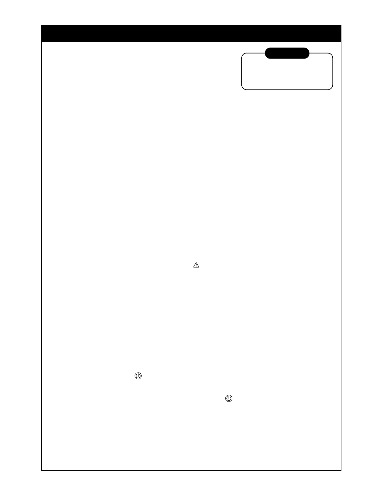
WARNING
Turn on the power supply
12 hours or more before
starting the air conditioner.
AIR CONDITIONER OPERATIONS AND PERFORMANCE
Check before operation
• Check whether earth wire is disconnected or out of place.
• Check that air filter is installed to the indoor unit.
Heating capacity (for Heat-pump model only)
• During heating operation the heat pump system operates by
absorbing the heat from the outside air and discharging it into the room.
Therefore if the outside temperature drops, the units heating capacity will decrease.
• When temperature of the outside air is low, it is recommended that you use other forms of heating in con-
junction with the air conditioner.
Defrost operation during heating operation (for Heat-pump model only)
• If the outdoor unit has a build up of frost during the heating operation, the operation mode changes automati-
cally to defrost mode to increase the heating effect (for approximately 2 to 10 minutes).
• During defrost operation, fans of the indoor and the outdoor units will stop.
Protection for 3 minutes
• The outdoor unit will not operate for approximately 3 minutes after the air conditioner has been immediately
restarted after being stop, or the power supply has been turned on. This is to protect the system.
Main power failure
• If a power failure occurs during operation, all operations stop.
• When restarting the unit, push the ON/OFF button again.
Fan rotation of stopped unit
• When other indoor units within the same system are in operation, the fan on the indoor units that are on
“stand-by” will rotate to protect the machine once approximately 1 hour for several minutes.
Protective device (High pressure switch)
The high pressure switch operates the unit automatically when excessive load is applied to the air conditioner.
If the protective device operates, the operation lamp will stay but the operation will stop.
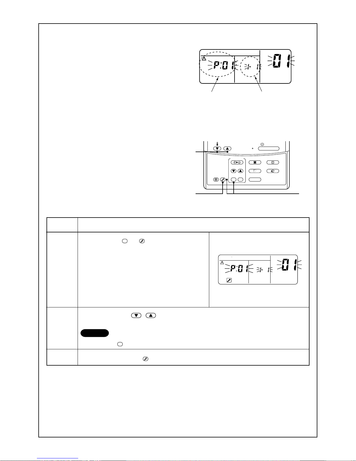
When the protective device operates, check characters “
” on the remote controller display.
The protective device may operate in the following cases.
In Cooling operation
• When suction or discharge port of the outdoor unit is closed.
• When strong winds blow continuously against the discharge port of the outdoor unit.
In Heating operation (For Heat-pump model only)
• When excessive dirt or dust is adhered to the air filter of the indoor unit.
• When the discharge port of the indoor unit is blocked.
Cooling/heating operation of MiNi-SMMS air conditioner
In MiNi-SMMS air conditioner, each indoor unit can be individually controlled. However, cooling operation and
heating operation cannot be performed concurrently for the indoor units, which are connected to the same
outdoor unit.
When cooling operation and heating operation are performed concurrently, the indoor unit which is performing
cooling operation stops, and the “
” on the unit display will be lit. The indoor unit that is in heating mode will
continue operation.
If the manager has fixed the setting to COOL or HEAT, no other operation can be performed.
When another operation other than the set up one is performed, the “
” light is displayed on the display part
of the indoor unit.
Characteristics of heating operation (For Heat-pump model only)
• Hot air will not be blown out immediately from the indoor unit. It will take between 3 to 5 minutes (depending
on temperature conditions of the room and the outside) before the indoor heat exchanger warms up sufficiently, to allow hot air to be blown.
• During operation, the outdoor unit may stop if the outside temperature becomes to high.
• When other indoor units are in heating operation, the fan operation of the indoor unit on fan only operation
may be stopped temporarily to prevent hot air from being blown out.
23
Air conditioner operating conditions
For the specified performance, operate the air conditioner under the following temperature conditions:
If air conditioner is used outside of the above conditions the units, safety protection devices may operate.
RE-INSTALLATION
DANGER
If the unit position is to be changed and re-located to a new position ask your local dealer or installation specialist. Do not attempt to move the air conditioner yourself, as incorrect installation may
cause electric shock or fire.
Do not install the air conditioner in the following places
• Do not install the air conditioner in any place within 1 m from a TV, stereo, or radio set. If the unit is installed
in such places, noise transmitted from the air conditioner may effect the operation of these appliances.
• Do not install the air conditioner near a high frequency appliance (sewing machine or massager for business
use, etc.), as the air conditioner may malfunction.
• Do not install the air conditioner in a humid or oily place, or in a place where steam, soot, or corrosive gas
may be generated.
• Do not install the air conditioner in a salty place such as a seaside area.
• Do not install the air conditioner in a place where a great deal of machine oil is used.
• Do not install the air conditioner in a place where it is usually exposed to strong winds such as in a seaside
area or on the roof / upper floor of a building.
• Do not install the air conditioner in a place where sulfureous gas may be generated such as in a spa.
• Do not install the air conditioner in a vessel or mobile crane.
Be careful with noise or vibrations
• Do not install the air conditioner in a place where the noise or the hot air created by the outdoor unit will
come into contact with your neighbours.
• Install the air conditioner on a solid and stable foundation as this will reduce the transmission of noise and
vibration that is produced from the outdoor unit.
• If one indoor unit is operating, some sound may be audible from other indoor units that are connected within
the same system (even when not in operation).
Cooling operation
Heating operation
Outdoor temperature : –5°C to 43°C (Dry-bulb temp.)
Room temperature : 21°C to 32°C (Dry-bulb temp.), 15°C to 24°C (Wet-bulb temp.)
CAUTION
Room relative humidity – less than 80 %. If the air conditioner operates
in excess of this figure, the surface of the air conditioner may cause dewing.
Outdoor temperature : –15°C to 15.5°C (Wet-bulb temp.)
Room temperature : 15°C to 28°C (Dry-bulb temp.)
The slot provided at side surface of the outdoor
unit is an air intake for cooling the electrical parts.
If the air intake would be clogged, a trouble is
caused on the electrical parts.
Therefore never close the air intake or do not
place any obstacle near the air intake.
Slot for air intake
24
Silent
It’s strange.
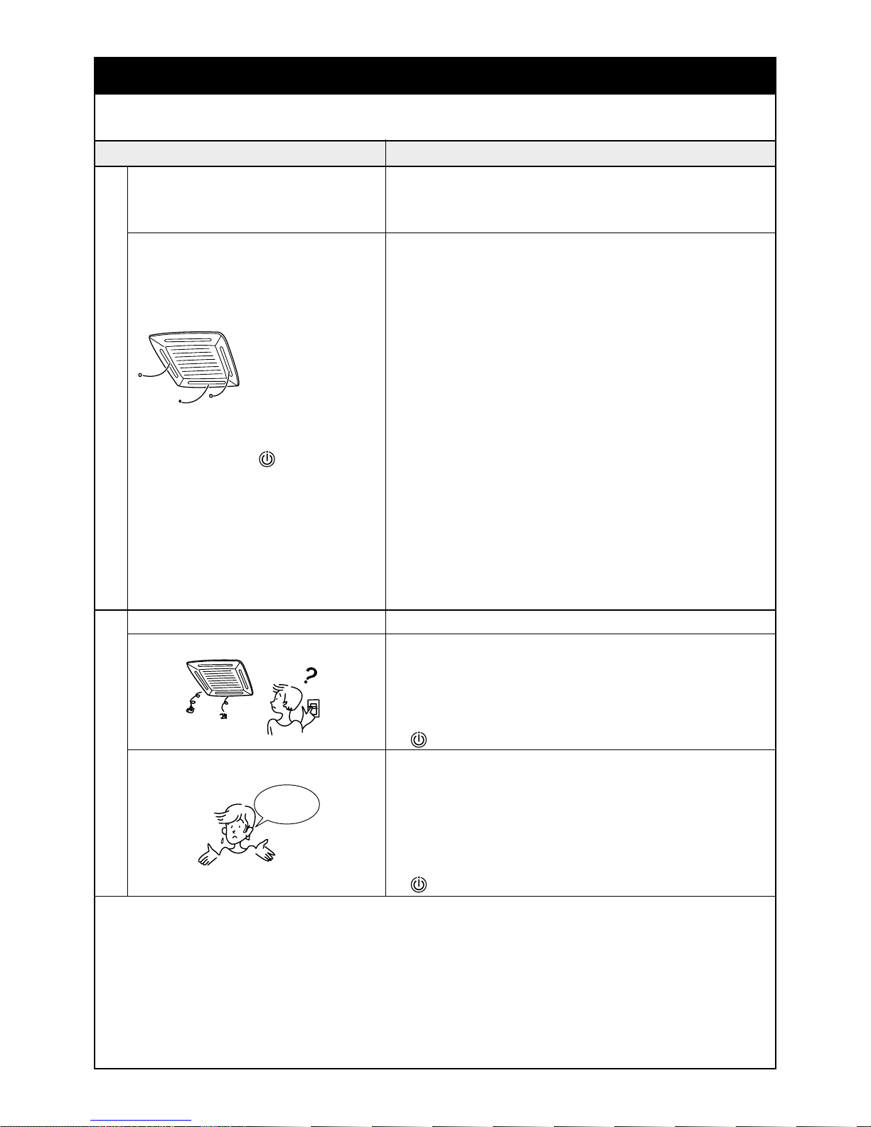
WHEN THE FOLLO WING SYMPTOMS ARE FOUND
Check the points described below before contacting your local service repair center.
Check again.
It is not a failure.
Cause
• Fan of the outdoor unit stops automatically and performs defrost
operation.
• Solenoid valve works when defrost operation starts or finishes.
• When the unit is in operation,a sound such as the movement of
water from one area to another may be heard. This sound may
become larger after a period of 2 to 3 minutes once the unit has
begun operation. This is not a cause for concern, but is the movement of the refrigerant or the draining sound of the dehumidifier.
• When the air conditioner system is operating, the stopping indoor
unit in the same system needs temporary flow of refrigerant to
prevent the stay of oil or refrigerant.
Therefore, refrigerant flow sound “shaa/cyu” may be heard, or white
vapor may come out when other indoor unit heating, or cool air
may come out when other indoor unit cooling.
• This sound is generated when the heat exchanger, etc. expands
and contracts slightly due to the change of temperature.
• Various odurs such as those from a carpet, clothes, cigarette, or
cosmetics will adhere to the air conditioner.
• When cooling operation cannot be performed because another
indoor unit performs heating operation.
• When the manager of the air conditioner has fixed the operation to
either COOL or HEAT, but a request or demand contrary to the
setup operation is requested.
• When the fan operation is stopped to prevent the discharge of hot
air.
• Sound is generated when the expansion valve operates when the
power supply has been turned on.
• Is the timer “ON” or “OFF”?
• Is there a power failure to the unit?
• Has the power supply been turned off?
• Has the power fuse or breaker blown?
• Has the protective device operated? (The operation lamp goes on.)
• Is the timer “ON”? (The operation lamp goes on.)
• Are COOL and HEAT selected simultaneously?
(“
” indication is lit on the display column of the remote controller.)
• Is the suction port or discharge port of the outdoor unit obstructed?
• Are there any doors or windows open?
• Is the air filter clogged with dust?
• Is the discharge louver of the indoor unit set at appropriate position?
• Is the air selection set to “LOW” or “MED” and is the operation
mode set to “FAN”?
• Is the setup temp. the appropriate temperature?
• Are COOL and HEAT selected simultaneously?
(“ ” indication is lit on the display column of the remote controller.)
Symptom
Outdoor unit • White misty cold air or
water is blown out.
• Sometimes, the noise
“Pushu !” is heard.
Indoor unit •“Swish” sound is
sometimes heard.
• A stopping indoor unit
in the same operating
air conditioner system
emitted sound, white
vapor or cool air.
• Slight “Pishi!” sound is
heard.
• Discharge air smells.
•“
” indication is lit.
• When power of the air
conditioner is turned
on, “Ticktock” sound is
heard.
Operates or stops automatically.
Does not operate.
Air is not cooled or warmed sufficiently.
When the following symptoms are found, stop the operation immediately, tur n off the power supply, and contact the dealer from where you have purchased the air conditioner.
• Activation of the power supply causing the unit to operate in an unstable fashion
(power on, power off , power on, power off etc).
• The main power fuse often blows out, or circuit breaker is often activated.
• Foreign matters or water have entered the unit by mistake.
• When the unit fails to operate after the protective device (circuit breaker) has been removed.
Not recommended.
• Other unexplained symptoms or unit abnormalities, that cannot be explained.
25
3
2
1
ON / OFF
FAN
TEMP.
SWING/FIXTIME
MODE
VENT
UNITSET CL
FILTER
RESET
TEST
TIMER SET
CODE No.
UNIT No.
R.C. No.
Confirmation and check
When a error has occurred in the air conditioner, the
check code and the indoor unit No. will appear on
the display part of the remote controller.
The check code is only displayed during while the
unit is operating.
If the display disappears, operate the air conditioner
according to the following “Confirmation of error
history” for confirmation.
Confirmation of error history
When a error has occurred on the air conditioner,
the error history can be confirmed with the following
procedure. (up to 4 errors can be stored in the
memory of the remote controller)
The history can be confirmed from both operating
status and stop status.
Procedure
1
2
3
Description
When pushing the
SET
and
TEST
buttons at the same time
for 4 seconds or more, the following display will appear.
If [Service check] is displayed, the mode enters into the
error history mode.
• [01 : Order of error history] is displayed in CODE No.
window.
• [Check code] is displayed in CHECK window.
• [Indoor unit address in which the error has occurred]
is displayed in UNIT No.
For every push of the [ , ] button, the error history stored in memory is displayed in order.
The numbers in CODE No. indicate CODE No. [01] (latest) → [04] (oldest).
CAUTION
Do not push the
CL
button because all the error history of the indoor unit will be deleted.
After confirmation, push the
TEST
button to return to the normal display.
1. Check the error codes according to the above procedure.
2. Ask an authorized dealer or qualified service (maintenance) professional to repair or maintain the air conditioner.
3. More details of the service codes are explained in the Service Manual.
Check code
Indoor unit No. in which
an error occurred
CODE No.
UNIT No.
R.C. No.
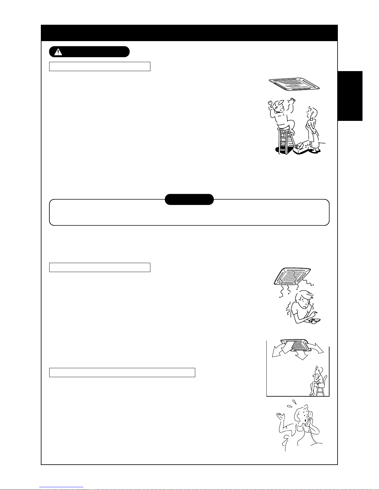
26
MESURES DE SECURITE
AVERTISSEMENT
Avertissement sur le montage
Confiez les travaux de montage au revendeur ou à un atelier
spécialisé.
Pour effectuer les travaux de montage il est indispensable d’avoir des
connaissances techniques approfondies.
N’essayez pas de le monter vous-mêmes. Un montage incomplet risque de
provoquer une électrocution, des b lessures , des fuites d’eau ou un incendie .
Vérifiez si les produits vendus séparément sont ceux que nous
avons indiqués.
Vérifiez si les produits vendus séparément sont ceux que nous av ons indiqués .
Autrement vous pourriez provoquer une électrocution, des blessures, des
fuites d’eau ou un incendie. Pour les travaux de montage adressez-vous à un
technicien spécialisé.
Si vous montez l’unité dans une petite pièce, prenez des mesures
afin que les fuites éventuelles de réfrigérant ne dépassent pas la
concentration critique.
PRUDENCE
Dans ce but, effectuez les travaux de montage après avoir demandé son avis à votre revendeur.
Si le réfrigérant fuit et dépasse la concentration critique, l’oxygène risque de venir à manquer.
Contrôlez si les travaux de mise à la terre sont effectués correctement
La mise à la terre est nécessaire. Une mise à la terre incomplète risque de provoquer une électrocution.
(Pour les détails , respectez scrupuleusement la réglementation locale de chaque pays).
Avertissement sur l’utilisation
Evitez d’exposer directement à l’air froid pendant longtemps une
quelconque partie de votre corps et de trop vous refroidir.
Cela pourrait nuire à votre condition ph ysique et à votre santé.
N’introduisez jamais ni barre ni doigt dans la bouche d’aspiration ou
dans la bouche de soufflage.
Le ventilateur à l’intérieur de l’unité tourne très vite et pourrait vous blesser.
Si vous sentez une odeur suspecte (odeur de brûlé, etc..) arrêtez le
fonctionnement, coupez l’alimentation électrique et adressez-vous
au revendeur du climatiseur.
Si vous laissez le climatiseur f onctionner en mauvais état vous pourriez
provoquer un incendie, une électrocution ou un autre prob lème .
Avertissement sur la manutention/réparation
Ne modifiez jamais le climatiseur.
Vous risqueriez de provoquer un incendie ou une électrocution.
Pour les réparations, contactez le revendeur du climatiseur.
Une réparation incomplète risque de provoquer une électrocution, des
blessures, des fuites d’eau ou un incendie.
Pour déplacer ou réinstaller le climatiseur, adressez-vous au
revendeur du climatiseur ou à un technicien spécialisé.
Un montage incomplet risque de provoquer une électrocution, des blessures,
des fuites d’eau ou un incendie.
FRANCAIS
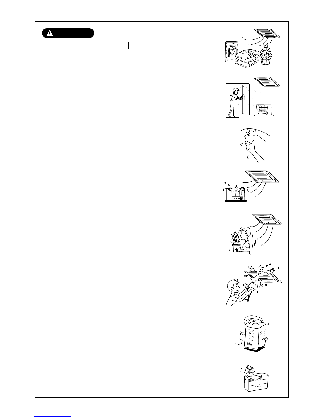
27
PRUDENCE
Prudence pendant le montage
Vérifiez si les tuyaux d’évacuation sont montés afin d’évacuer
correctement l’eau d’évacuation.
Si la tuyauterie est incomplète, les fuites d’eau risquent de mouiller les
meubles.
Vérifiez si le disjoncteur est branché.
En cas de besoin installez-en un. Si vous ne le faites pas vous pourriez
vous électrocuter.
Vérifiez si le climatiseur est monté loin de tout risque de fuite de
gaz.
Les fuites et l’accumulation de gaz autour de l’appareil risquent de
provoquer un incendie.
Vérifiez si l’unité extérieure est fixée sur son socle.
Si elle n’est pas solidement fixée sur son socle elle peut provoquer un
accident, par exemple en tombant.
Vérifiez la méthode de fixation
Ne nettoyez pas le climatiseur avec de l’eau.
Vous risqueriez de vous électrocuter.
Ne placez pas d’appareil de chauffage directement dans le flux
d’air du climatiseur.
Vous risqueriez de nuire à la combustion du combustible de cet appareil.
Aérez correctement la pièce lorsque vous utilisez le climatiseur
en même temps qu’un appareil de chauffage.
Si l’aération n’est pas bonne, l’oxygène risque de manquer.
Après un certain temps, vérifiez si la plaque de montage, etc…
n’est pas endommagée.
Si vous ne la changez pas lorsqu’elle est endommagée, l’appareil risque de
tomber et de blesser quelqu’un, etc..
Ne placez ni plantes ni animaux directement dans le flux d’air
du climatiseur.
Vous risqueriez de nuire à ces animaux et à ces plantes.
Ne laissez pas de produits en bombe à proximité du climatiseur et
ne pulvérisez pas de produit directement sur le climatiseur.
Vous risqueriez de provoquer un incendie.
Ne posez aucune récipient plein d’eau, comme des vases, sur
l’appareil.
En pénétrant dans l’unité détériore l’isolation électrique et risque de
provoquer une électrocution.
Ne manipulez pas les interrupteurs avec les mains humides.
Vous risqueriez de vous électrocuter.
N’utilisez pas le climatiseur pour entreposer des aliments, des
plantes, des animaux, des appareils de précision et des œuvres
d’art.
Il pourrait les endommager .
 Loading...