

Page 1
DESIGN MANUAL
Heat Recovery Type (2 Series)
FILE NO. A04-017
R410A
Indoor Unit
<4-way Air Discharge Cassette Type>
MMU-AP0091H, AP0121H, AP0151H,
MMU-AP0181H, AP0241H, AP0271H,
MMU-AP0301H, AP0361H, AP0481H
MMU-AP0561H
<2-way Air Discharge Cassette Type>
MMU-AP0071WH, AP0091WH, AP0121WH,
MMU-AP0151WH, AP0181WH, AP0241WH,
MMU-AP0271WH, AP0301WH, AP0481WH*
* CHINA market only
<1-way Air Discharge Cassette Type>
MMU-AP0071YH, AP0091YH, AP0121YH,
MMU-AP0151SH, AP0181SH, AP0241SH
<Concealed Duct Standard Type>
MMD-AP0071BH, AP0091BH, AP0121BH,
MMD-AP0151BH, AP0181BH, AP0241BH,
MMD-AP0271BH, AP0301BH, AP0361BH,
MMD-AP0481BH, AP0561BH
<Concealed Duct High Static Pressure Type>
MMD-AP0181H, AP0241H, AP0271H,
MMD-AP0361H, AP0481H, AP0721H,
MMD-AP0961H
<Under Ceiling Type>
MMC-AP0151H, AP0181H, AP0241H,
MMC-AP0271H, AP0361H, AP0481H
<High Wall Type>
MMK-AP0071H, AP0091H, AP0121H,
MMK-AP0151H, AP0181H, AP0241H,
MMK-AP0072H*, AP0092H*, AP0122H*
* European market only
<Floor Standing Cabinet Type>
MML-AP0071H, AP0091H, AP0121H,
MML-AP0151H, AP0181H, AP0241H
<Floor Standing Concealed Type>
MML-AP0071BH, AP0091BH, AP0121BH,
MML-AP0151BH, AP0181BH, AP0241BH
<Floor Standing Type>
MMF-AP0151H, AP0181H, AP0241H
MMF-AP0271H, AP0361H, AP0481H
MMF-AP0561H
Outdoor Unit
<Inverter Unit>
MMY-MAP0802FT8
MMY-MAP1002FT8
MMY-MAP1202FT8
FS unit
RBM-Y1122FE
RBM-Y1802FE
RBM-Y2802FE
PRINTED IN JAPAN, 2005
Page 2

CONTENTS
DESIGN MANUAL ..................................................................3
1. OUTLINE OF TOSHIBA SUPER HRM
(Super Heat Recovery Multi System) ................................................. 3
2. SUMMARY OF SYSTEM EQUIPMENTS .............................................. 6
3. BASIC SYSTEM CONFIGURATION ................................................... 11
4. EQUIPMENT SELECTION PROCEDURE .......................................... 16
5. REFRIGERANT PIPING DESIGN ....................................................... 25
6. WIRING DESIGN ................................................................................. 30
7. CONTROLS ......................................................................................... 35
8. ACCESSORIES ................................................................................... 41
9. TECHNICAL SPECIFICATIONS.......................................................... 44
10. FAN CHARACTERISTICS .................................................................. 59
11. DIMENSIONAL DRAWINGS ............................................................... 62
Page 3
DESIGN MANUAL
1. OUTLINE OF TOSHIBA SUPER HRM
(Super Heat Recovery Multi System)
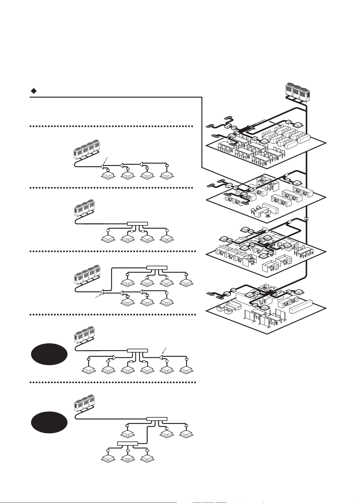
Shortest route design by free branching
Combination of line and header branching is highly flexible.
This follows for the shortest design route possible, thereby saving
on installation time and cost. Line/header branching after
header branching is only available with TOSHIBA Super HRM.
Line branching
Outdoor unit
Branching joint
FS unit
Indoor unit
Header branching
Outdoor unit
Branching
header
FS unit
Indoor unit
Line + Header branching
Outdoor unit
Branching joint
Indoor
unit
Header
Line branching after header branching
Outdoor unit
8F
7F
2F
FS
unit
1F
Branching joint
Super HRM
MMS Only
Only
Indoor unit
Header
Header branching after header branching
Outdoor unit
Header
Super HRM
Only
Header
FS unit
Indoor unit
3
FS unit
Page 4
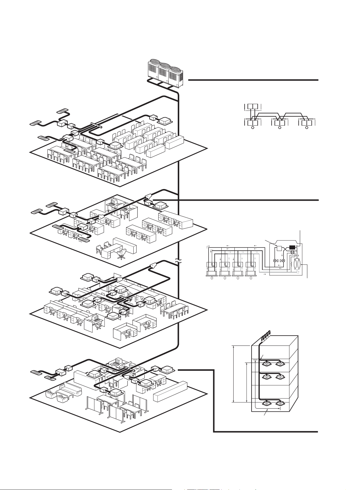
• Non-polarized control wiring
between outdoor and indoor units
8F
7F
Outdoor unit
Indoor unit
FS unit
Indoor
unit
Heating Cooling Cooling Cooling
• Simultaneous operation
U1 U2
U1 U2 U1 U2 U1 U2
main heat exchanger
Sub heat exchanger
Outdoor unit
Compressor
2F
1F
Allowable pipe length :
Outdoor
unit
Height difference between indoor
unit and indoor unit : 35m
Height difference between indoor
unit and outdoor unit : 50m
From 1st branching to the
farthest indoor unit : 50m
150m equivalent length
1st branching
section
4
Page 5
Energy saving
No. 1 COP in heat recovery VRF industry. Compared with the conventional chiller fan coil system,
a large energy saving can be realized.
Advanced bus communication system
Wiring between indoor and outdoor unit is a simple 2 wire system.
Communication address is also automatically configured.
A default test mode operation is available.
Self diagnostics system
Comprehensive troubleshooting code allows for timely identification of problems arising.
High lift and flexible piping design
Equivalent pipe length of 150m and vertical lift of 50m is made possible with TOSHIBA Super HRM.
Vertical lift between indoor units of 35m is the highest in the industry.
Also, maximum piping length from 1st branching is 50m.
These allow for greater flexibility in the location of the system.
Simultaneous operation
By controling the FS unit, Super HRM enables freely simultaneous operation of cooling and heating.
This operation meets the various needs of modern buildings that has highly airtight or an increasing
heat load due to use of computers. Also, Super HRM improves energy efficiency by recycling
exhaust heat.
Extended outdoor temperature operating range
By employing sophisticated system control with all inverter driven compressor, the operating range
in cooling has been extended from -5ºC to -10ºC.
Compact FS unit design
The compact and light weight design of the FS unit (Flow selector unit) allows it to be easily
installed in limited spaces.
Group control by one FS unit
Up to 8 indoor units of group control by one FS unit gives the design flexibility for various type and
size of rooms.
Intelligent control
TOSHIBA Super HRM intelligent controls and modulating valves deliver the required capacity,
according to the load variation from 50% to 100%.
The intelligent controls and modulating valves limit or increase the cooling capacity dynamically so
humidity and temperature are kept in the comfort zone.
Conforms to building control law
IAQ (Indoor Air Quality) is also achieved by combining various accessories required by the Building
Control Law.
Wide control applications
Artificial Intelligence Network system
• Central control and monitoring system available
• Weekly schedule operation through weekly timer
Integration with Building Management System (BMS) is available.
5
Page 6
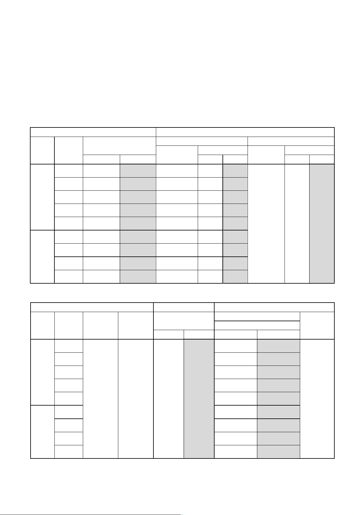
2. SUMMARY OF SYSTEM EQUIPMENTS
Equipments
1. Outdoor units
Inverter unit
8HP 10HP 12HP
Model name MMY- MAP0802FT8 MAP1002FT8 MAP1202FT8
Cooling capacity (kW) 22.4 28.0 33.5
Heating capacity (kW) 25.0 31.5 35.5
2. Outdoor units (Combination of outdoor units)
Corresponding HP
Combined model
Cooling capacity (kW)
Heating capacity (kW)
Combined outdoor units
No. of connectable indoor units
Corresponding HP
Combined model
Cooling capacity (kW)
Heating capacity (kW)
Combined outdoor units
No. of connectable indoor units
MMY- MAP0802FT8
MMY- AP2002FT8
8HP
22.4
25
8HP
13
20HP
56
63
10HP
10HP
33
10HP
MAP1002FT8
28
31.5
10HP
16
24HP
AP2402FT8
68
76.5
8HP
8HP
8HP
40
12HP
MAP1202FT8
33.5
35.5
12HP
16
26HP
AP2602FT8
73
81.5
10HP
8HP
8HP
43
AP1602FT8
AP2802FT8
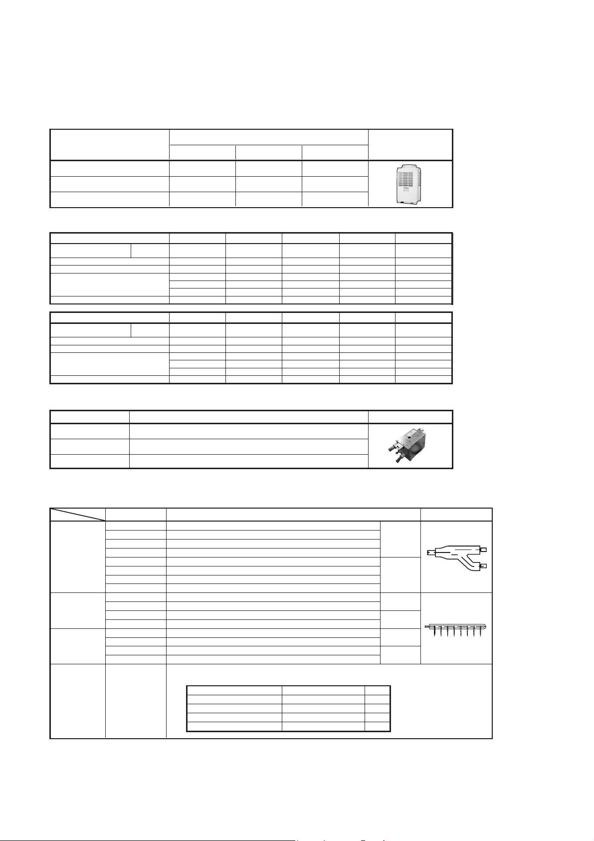
3. FS units (Flow selector units)
Model name Usage
RBM-Y1122FE
RBM-Y1802FE
RBM-Y2802FE Total capacity for indoor unit : 18.0 to 28.0 kw or less
Total capacity for indoor unit : Below 11.2 kw
Total capacity for indoor unit : 11.2 to below 18.0 kw
16HP
45
50
8HP
8HP
27
28HP
78.5
88
10HP
10HP
8HP
47
AppearanceCorresponding HP
AP1802FT8
AP3002FT8
Appearance
18HP
50.4
56.5
10HP
8HP
30
30HP
84
95
10HP
10HP
10HP
48
Accessory part (Sold separately): Connection cable kit (RBC-CBK15FE), up to 15m.
*
4. Branching joints and headers
Model name Appearance
RBM-BY53FE
Y-shape
branching
joint (*3)
4-branching
header (*4) (*5)
8-branching
header (*4) (*5)
T-shape
branching
joint (For
connection
of outdoor
units)
1 “Capacity code” can be obtained from page 8. (Capacity code is not actual capacity)
*
2 If total capacity code value of indoor unit exceeds that of outdoor unit, apply capacity code of outdoor unit.
*
3 When using Y-shape branching joint for 1st branching, select according to capacity code of outdoor unit.
*
4 Max. 6.0 capacity code in total can be connected.
*
5 If capacity code of outdoor unit is 26 or more, it is not used for 1st branching.
*
6 This is used for branching to “cooling only” indoor unit.
*
7 Model names for outdoor and indoor units described in this guide are shortened because of the space constraint.
*
RBM-BY203FE
RBM-BY303FE
RBM-BY53E
RBM-BY103E
RBM-BY203E
RBM-BY303E
RBM-HY1043FE
RBM-HY2043FE
RBM-HY1043E
RBM-HY2043E
RBM-HY1083FE
RBM-HY2083FE
RBM-HY1083E
RBM-HY2083E
RBM-BT13FE
Indoor unit capacity code (*1) : Total below 6.4
Indoor unit capacity code (*1) : Total 6.4 or more and below 14.2RBM-BY103FE
Indoor unit capacity code (*1) : Total 14.2 or more and below 25.2
Indoor unit capacity code (*1) : Total 25.2 or more
Indoor unit capacity code (*1) : Total below 6.4
Indoor unit capacity code (*1) : Total 6.4 or more and below 14.2
Indoor unit capacity code (*1) : Total 14.2 or more and below 25.2
Indoor unit capacity code (*1) : Total 25.2 or more
Indoor unit capacity code (*1) : Total below 14.2
Indoor unit capacity code (*1) : Total 14.2 or more and below 25.2
Indoor unit capacity code (*1) : Total below 14.2
Indoor unit capacity code (*1) : Total 14.2 or more and below 25.2
Indoor unit capacity code (*1) : Total below 14.2
Indoor unit capacity code (*1) : Total 14.2 or more and below 25.2
Indoor unit capacity code (*1) : Total below 14.2
Indoor unit capacity code (*1) : Total 14.2 or more and below 25.2
1 set 4 types T-shape joint pipes as described below:
The required quantity is arranged and they are combined on site.
Connection piping Corresponded dia. (mm) Q'ty
Balance pipe
Piping at liquid side
Piping at discharge gas side
Piping at suction gas side
Usage
Ø 9.5 1
Ø12.7 to Ø22.2
Ø19.1 to Ø28.6
Ø22.2 to Ø38.1
6
For 3
piping
For 2
piping (*6)
For 3
piping
For 2
piping (*6)
For 3
piping
For 2
piping (*6)
1
1
1
Page 7
Super Heat Recovery Multi System Outdoor Unit
50Hz
HP (Capacity
code)
8HP ( 8) MAP0802HT8 1 MAP0802FT8 1
10HP (10) MAP1002HT8 1 MAP1002FT8 1
12HP (12) MAP1202HT8 1 MAP1202FT8* 1
16HP (16) 2 MAP0802FT8 2
18HP (18) 2 MAP0802FT8 1 MAP1002FT8 1
20HP (20) 2 MAP1002FT8 2
24HP (24) MAP0802FT8 3
26HP (26) MAP0802FT8 2 MAP1002FT8 1
28HP (28) MAP0802FT8 1 MAP1002FT8 2
30HP (30) MAP1002FT8 3
*
Model name
MMY-
12HP unit is for stand-alone usage only.
Outdoor unit combination with 12HP unit is not available.
No. of
combined
units
Inverter
8 HP
MMY-
Used
Q'ty
Inverter
10 HP
MMY-
Used
Q'ty
Inverter
12 HP
MMY-
Used
Q'ty
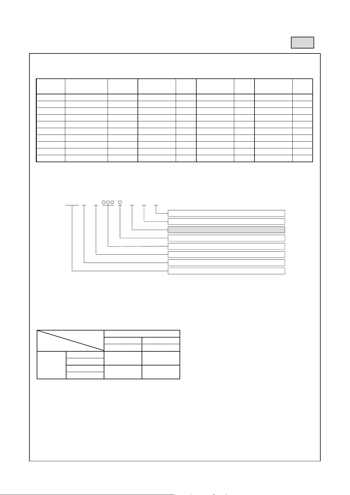
1. Allocation standard of model name
MMY– M AP T 8
F
Power supply specifications, 3Ø 380–415 V, 50Hz ....... 8
T : Capacity variable unit
F : Heat recovery
Development series No.
Capacity rank HP x 10
New refrigerant R410A
M : Single module unit, No mark : Combined Model name
Modular Multi
2. Rated conditions (Rated mode : Condition)
Cooling : Indoor air temperature 27°C DB/19°C WB, Outdoor air temperature 35°C DB
Heating : Indoor air temperature 20°C DB, Outdoor air temperature 7°C DB/6°C WB
3. Compatibility with 1 Series
Oudoor unit MMY-
1 Series
FS unit
RBM-Y***1E
2 Series
RBM-Y***2E
2 series outdoor units cannot be used with 1 series outdoor units.
*
1 Series 2 Series*
-MAP**1FT8 -MAP**2FT8
OK NG
OK OK
7
Page 8
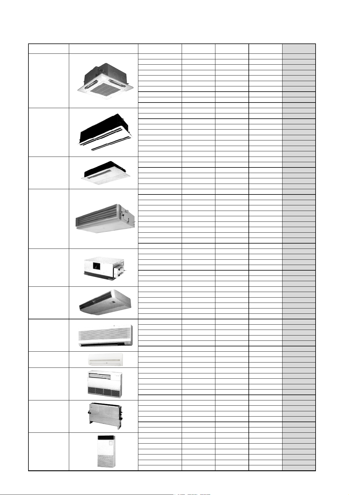
4. Indoor unit
*1) China only *2) European market only
Type Appearance Model name Capacity rank Capacity code
MMU-AP0091H 009 type 1 2.8 3.2
MMU-AP0121H 012 type 1.25 3.6 4.0
MMU-AP0151H 015 type 1.7 4.5 5.0
MMU-AP0181H 018 type 2 5.6 6.3
MMU-AP0241H 024 type 2.5 7.1 8.0
MMU-AP0271H 027 type 3 8.0 9.0
MMU-AP0301H 030 type 3.2 9.0 10.0
MMU-AP0361H 036 type 4 11.2 12.5
MMU-AP0481H 048 type 5 14.0 16.0
MMU-AP0561H 056 type 6 16.0
MMU-AP0071WH 007 type 0.8 2.2 2.5
MMU-AP0091WH 009 type 1 2.8 3.2
MMU-AP0121WH 012 type 1.25 3.6 4.0
MMU-AP0151WH 015 type 1.7 4.5 5.0
MMU-AP0181WH 018 type 2 5.6 6.3
MMU-AP0241WH 024 type 2.5 7.1 8.0
MMU-AP0271WH 027 type 3 8.0 9.0
MMU-AP0301WH 030 type 3.2 9.0 10.0
MMU-AP0481WH*
MMU-AP0071YH 007 type 0.8 2.2 2.5
MMU-AP0091YH 009 type 1 2.8 3.2
MMU-AP0121YH 012 type 1.25 3.6 4.0
MMU-AP0151SH 015 type 1.7 4.5 5.0
MMU-AP0181SH 018 type 2 5.6 6.3
MMU-AP0241SH 024 type 2.5 7.1
MMD-AP0071BH 007 type 0.8 2.2 2.5
MMD-AP0091BH 009 type 1 2.8 3.2
MMD-AP0121BH 012 type 1.25 3.6 4.0
MMD-AP0151BH 015 type 1.7 4.5 5.0
MMD-AP0181BH 018 type 2 5.6 6.3
MMD-AP0241BH 024 type 2.5 7.1 8.0
MMD-AP0271BH 027 type 3 8.0 9.0
MMD-AP0301BH 030 type 3.2 9.0 10.0
MMD-AP0361BH 036 type 4 11.2 12.5
MMD-AP0481BH 048 type 5 14.0 16.0
MMD-AP0561BH 056 type 6 16.0
MMD-AP0181H 018 type 2 5.6 6.3
MMD-AP0241H 024 type 2.5 7.1 8.0
MMD-AP0271H 027 type 3 8.0 9.0
MMD-AP0361H 036 type 4 11.2 12.5
MMD-AP0481H 048 type 5 14.0 16.0
MMD-AP0721H 072 type 8 22.4 25.0
MMD-AP0961H 096 type 10 28.0
MMC-AP0151H 015 type 1.7 4.5 5.0
MMC-AP0181H 018 type 2 5.6 6.3
MMC-AP0241H 024 type 2.5 7.1 8.0
MMC-AP0271H 027 type 3 8.0 9.0
MMC-AP0361H 036 type 4 11.2 12.5
MMC-AP0481H 048 type 5 14.0
MMK-AP0071H 007 type 0.8 2.2 2.5
MMK-AP0091H 009 type 1 2.8 3.2
MMK-AP0121H 012 type 1.25 3.6 4.0
MMK-AP0151H 015 type 1.7 4.5 5.0
MMK-AP0181H 018 type 2 5.6 6.3
MMK-AP0241H 024 type 2.5 7.1
MMK-AP0072H 007 type 0.8 2.2 2.5
MMK-AP0092H 009 type 1.0 2.8 3.2
MMK-AP0122H 012 type 1.25 3.6
MML-AP0071H 007 type 0.8 2.2 2.5
MML-AP0091H 009 type 1 2.8 3.2
MML-AP0121H 012 type 1.25 3.6 4.0
MML-AP0151H 015 type 1.7 4.5 5.0
MML-AP0181H 018 type 2 5.6 6.3
MML-AP0241H 024 type 2.5 7.1
MML-AP0071BH 007 type 0.8 2.2 2.5
MML-AP0091BH 009 type 1 2.8 3.2
MML-AP0121BH 012 type 1.25 3.6 4.0
MML-AP0151BH 015 type 1.7 4.5 5.0
MML-AP0181BH 018 type 2 5.6 6.3
MML-AP0241BH 024 type 2.5 7.1
MMF-AP0151H 015 type 1.7 4.5 5.0
MMF-AP0181H 018 type 2 5.6 6.3
MMF-AP0241H 024 type 2.5 7.1 8.0
MMF-AP0271H 027 type 3 8.0 9.0
MMF-AP0361H 036 type 4 11.2 12.5
MMF-AP0481H 048 type 5 14.0 16.0
MMF-AP0561H 056 type 6 16.0
1)
048 type 5 14.0 16.0
4-way Air Discharge
Cassette Type
2-way Air Discharge
Cassette Type
1-way Air Discharge
Cassette Type
Concealed Duct
Standard Type
Concealed Duct
High Static
Pressure Type
Under Ceiling Type
High Wall Type
(1 Series)
High Wall Type
(2 Series)
Floor Standing
Cabinet Type
Floor Standing
Concealed Type
Floor Standing Type
*2)
Cooling
capacity (kW)
8
Heating
capacity (kW)
18.0
8.0
18.0
31.5
16.0
8.0
4.0
8.0
8.0
18.0
Page 9
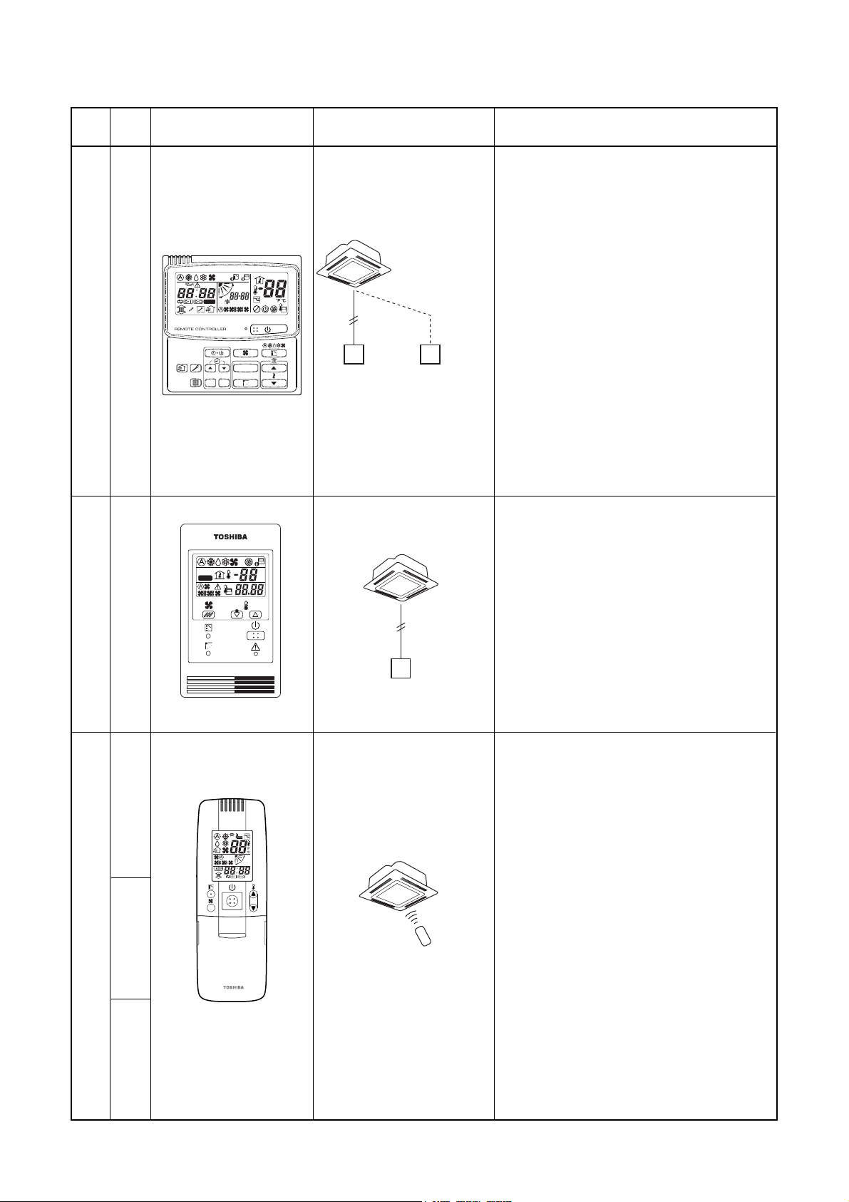
5. Remote controller
Name
Wired remote controller
Model
name
RBC-AMT21E
Appearance Application
Connected to indoor unit
UNIT No.
R.C. No.
UNIT
CODE No.
Wired remote
controller
Wired remote controller
(In case of control by
2 remote controllers)
SET DATA
SETTING
TEST
CL
SET
Connected to indoor unit
TEST
SETTING
˚C
˚F
Function
• Start / Stop
• Changing mode
• Temperature setting
• Air flow changing
• Timer function
Either “ON” time or “OFF” time or “CY-
CLIC” can be set how many 30 min. later
ON or OFF is operated.
Combined with the weekly timer, weekly
schedule operation can be operated.
• Filter sign
Displays automatically maintenance time of
indoor filter.
Filter sign flashes.
• Self-diagnosis function
Pressing “CHECK” button displays cause of
trouble on the check code.
• Control by 2 remote controllers is available.
Two remote controllers can be connected to
one indoor unit. The indoor unit can be
separately operated from the isolated places.
• Start / Stop
• Temperature setting
• Air flow changing
• Check code display
Simple remote controller
Wireless remote controller kit
RBC-AS21E
Simple remote controller
Connected to indoor unit
• Start / Stop
• Changing mode
• Temperature setting
• Air flow changing
• Timer function
Either “ON” time or “OFF” time or “CYCLIC”
can be set how many 30 min. later ON or OFF
is operated.
• Control by 2 remote controllers is available.
Two wireless remote controllers can operate
one indoor unit. The indoor unit can be
separately operated from the isolated places.
• Check code display
TCB-AX21U (W)-E
(For 4-way air discharge cassette)
RBC-AX22CE
(For under ceiling)
TCB-AX21E
(For others except concealed duct high static
pressure)
TCB-AX21E RBC-AX22CE TCB-AX21U (W)-E
9
Page 10
Name
Model
name
Appearance Application
Performance
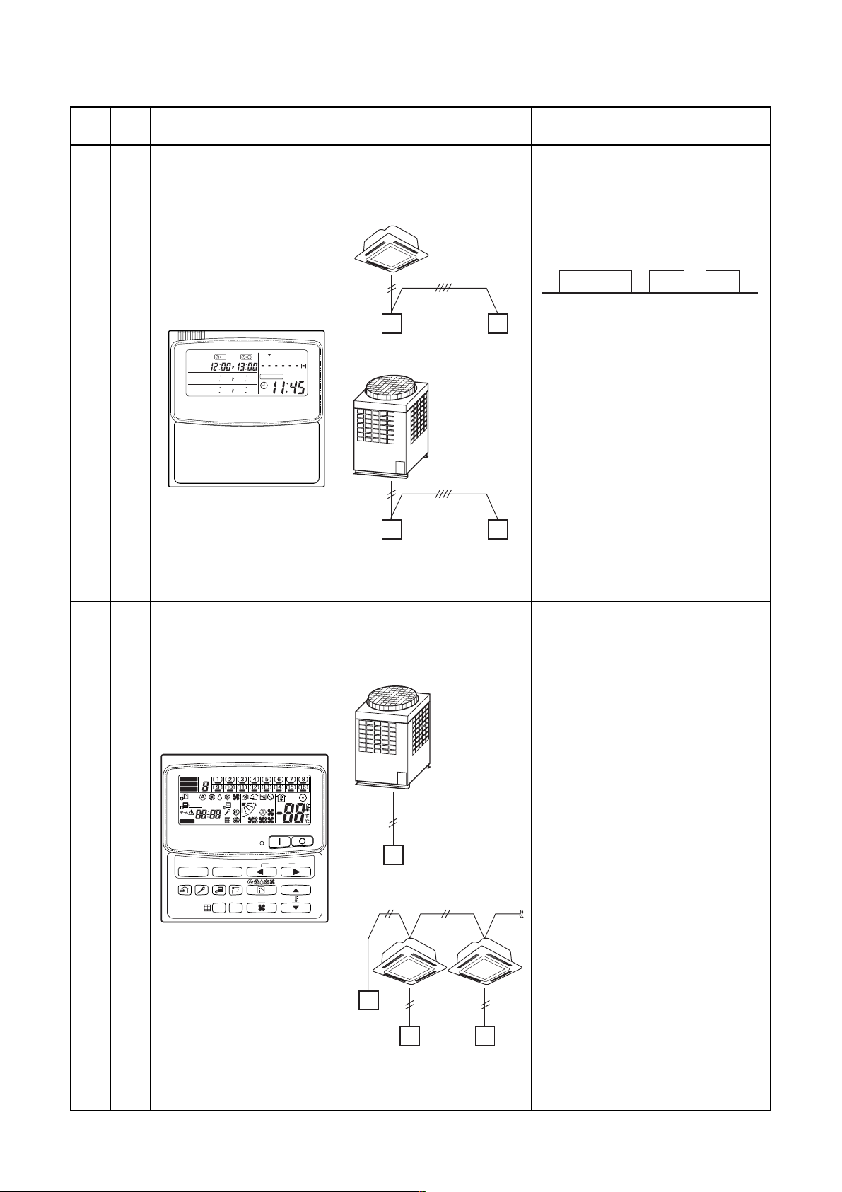
Weekly timer
RBC-EXW21E
PROGRAM1
PROGRAM2
PROGRAM3
WEEKLY TIMER
SuMoTuWeTh Fr Sa
ERROR
Connected to central
remote controller,
wired remote controller
Wired
remote controller
Outdoor unit
Central
remote controller
Weekly
timer
Weekly
timer
• Weekly schedule operation
Setting different start / stop time for
each day of the week
ON / OFF can be easily set 3 times
a day.
ON
8:00 12:00 13:00 18:00 19:00 21:00
“CHECK” “PROGRAM” “DAY”
OFF ON OFF ON OFF
button make setting copy easy.
Two patterns of schedule for a
week can be specified.
(Summer schedule and winter
schedule, etc.)
“CANCEL” “DAY” button make
holiday setting easy.
If power supply fails, the setting
contents are stored in memory, for
100 hours.
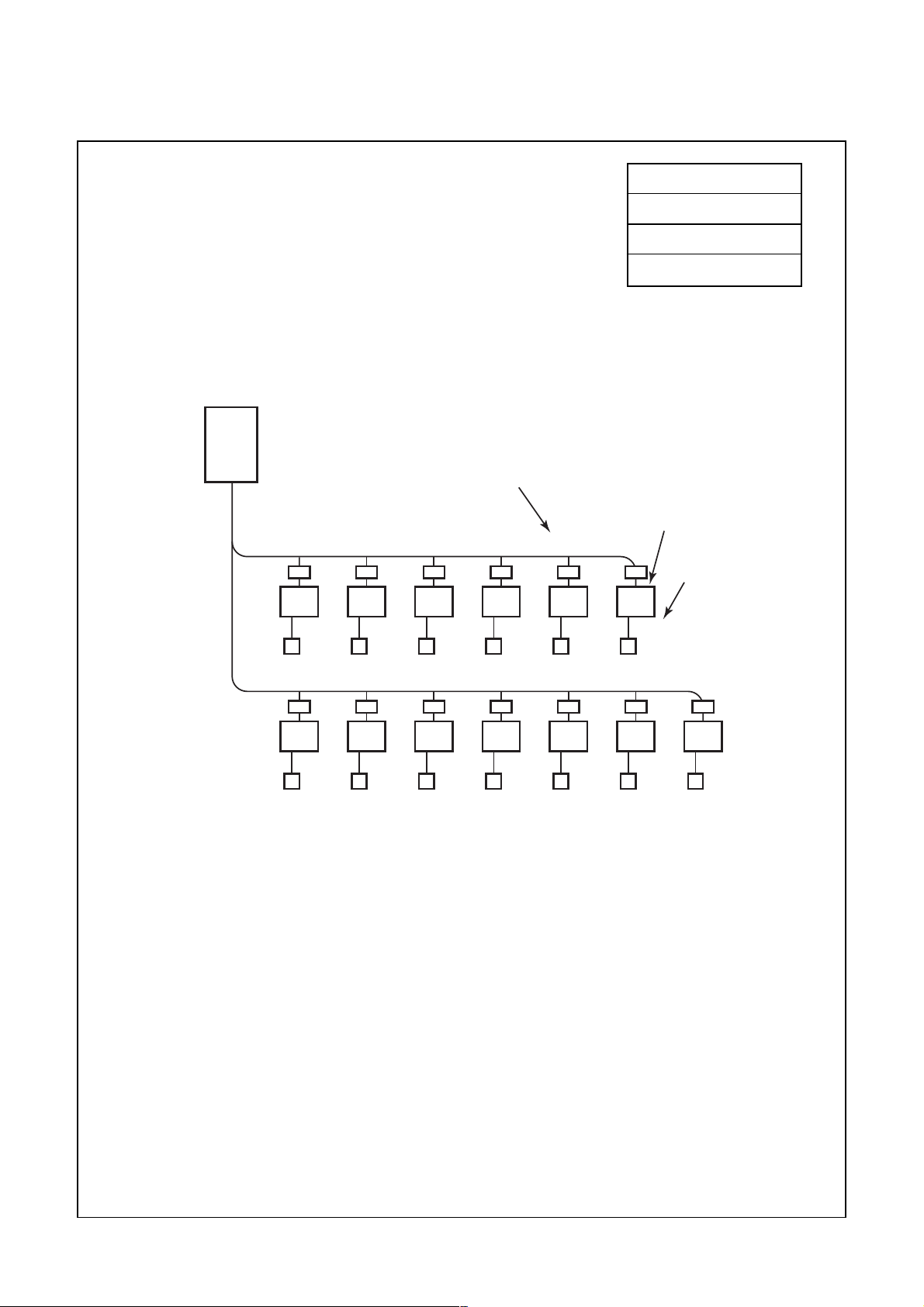
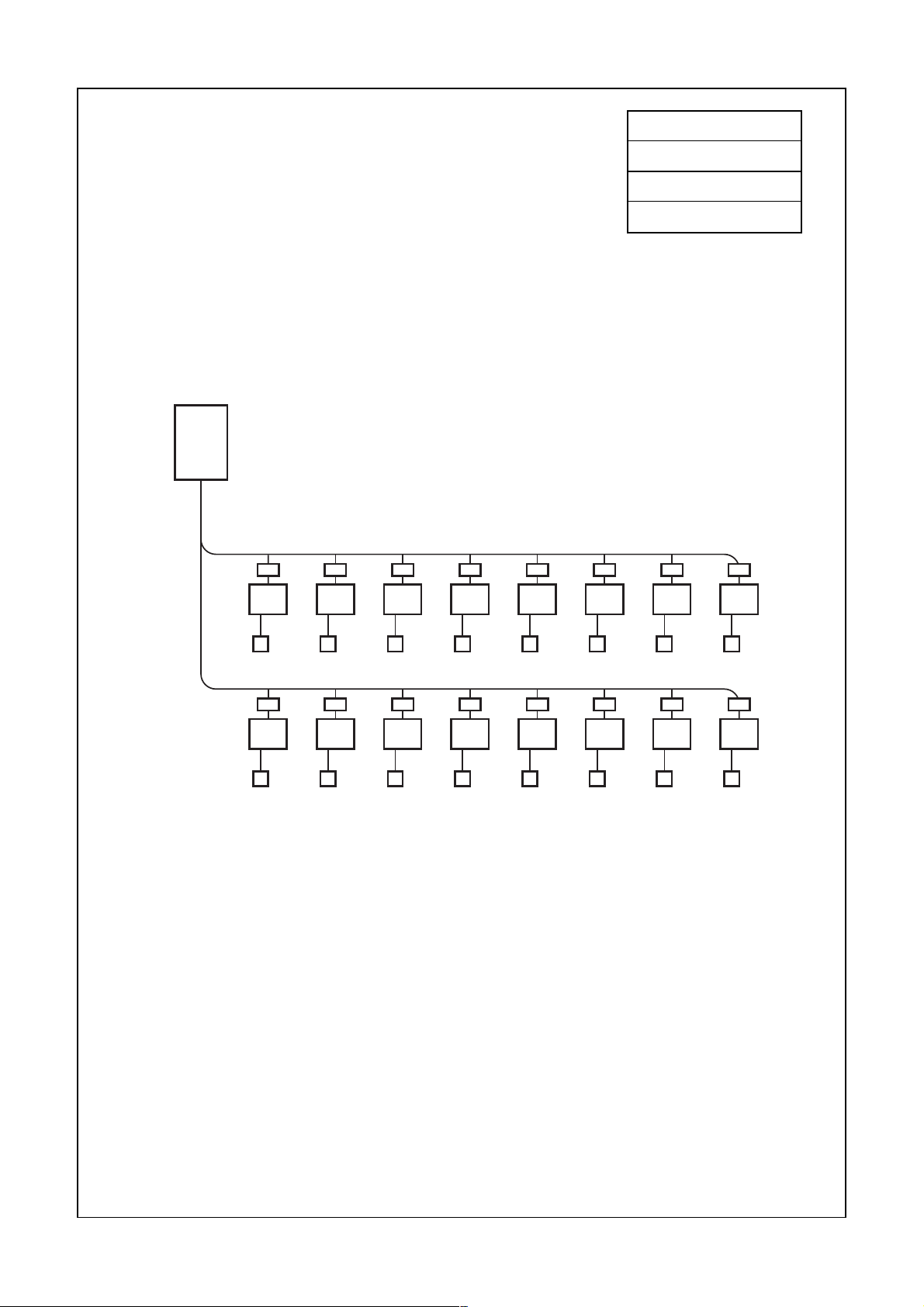
TCB-SC642TLE
Central remote controller
ZONE
ALL
ZONE
GROUP
1234
UNIT No.
SET DATA
SETTING
R.C.
No.
SELECT ZONE
CL
SET
Connected to outdoor unit,
indoor unit
Outdoor
unit
• Individual control for max. 64 indoor
units divided 1 to 4 zone.
Up to 16 indoor units for each
zone
• Up to 16 outdoor header units are
connectable.
• 4 type central control setting to inhibit
individual operation by remote
controller can be selected.
• Individual control up to 64 indoor units.
CODE
TEST
No.
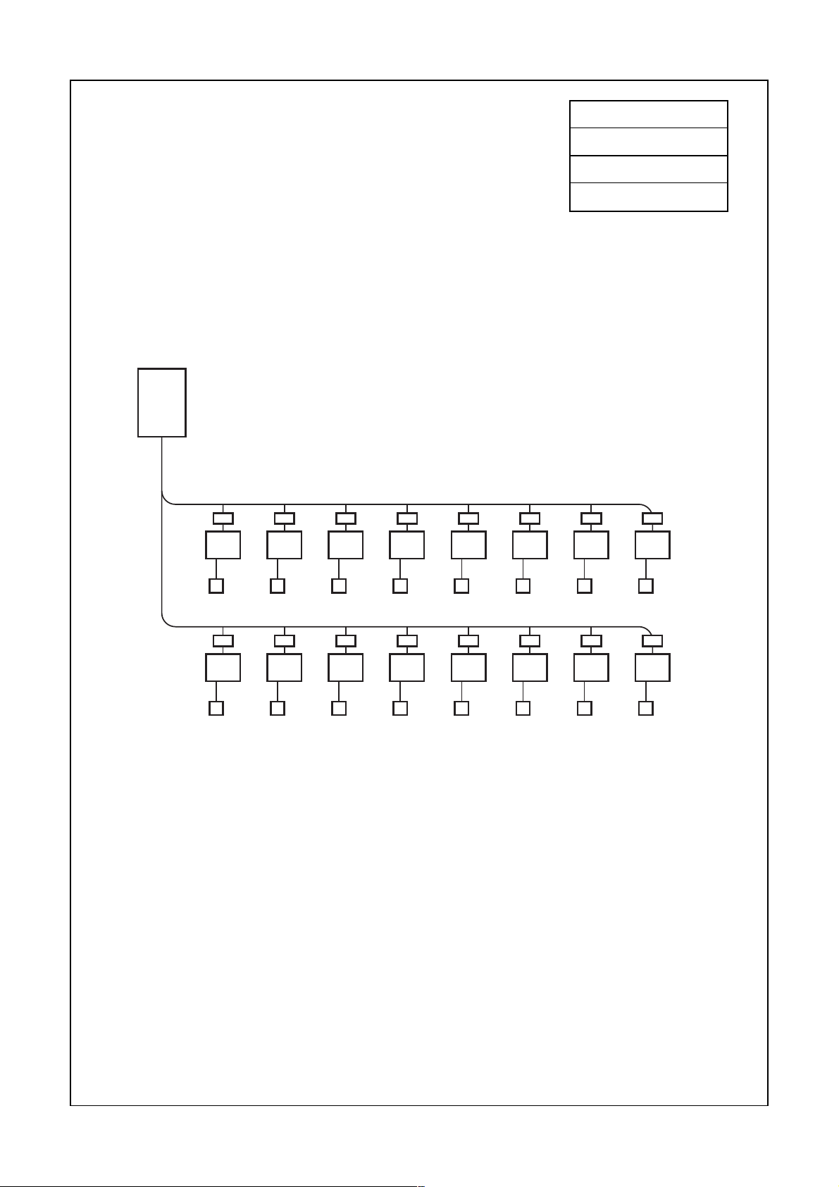
• Setting for one of 1 to 4 zone is
available.
• Usable with other central control
devices (Up to 10 central control
GROUP
Central
remote controller
devices in one control circuit)
• Two control mode selectivity
Central controller mode
Remote controller mode
• Setting of simultaneous ON/OFF 3
times for each day of the week
combined with weekly timer.
Central
remote
controller
Indoor
remote controller
10
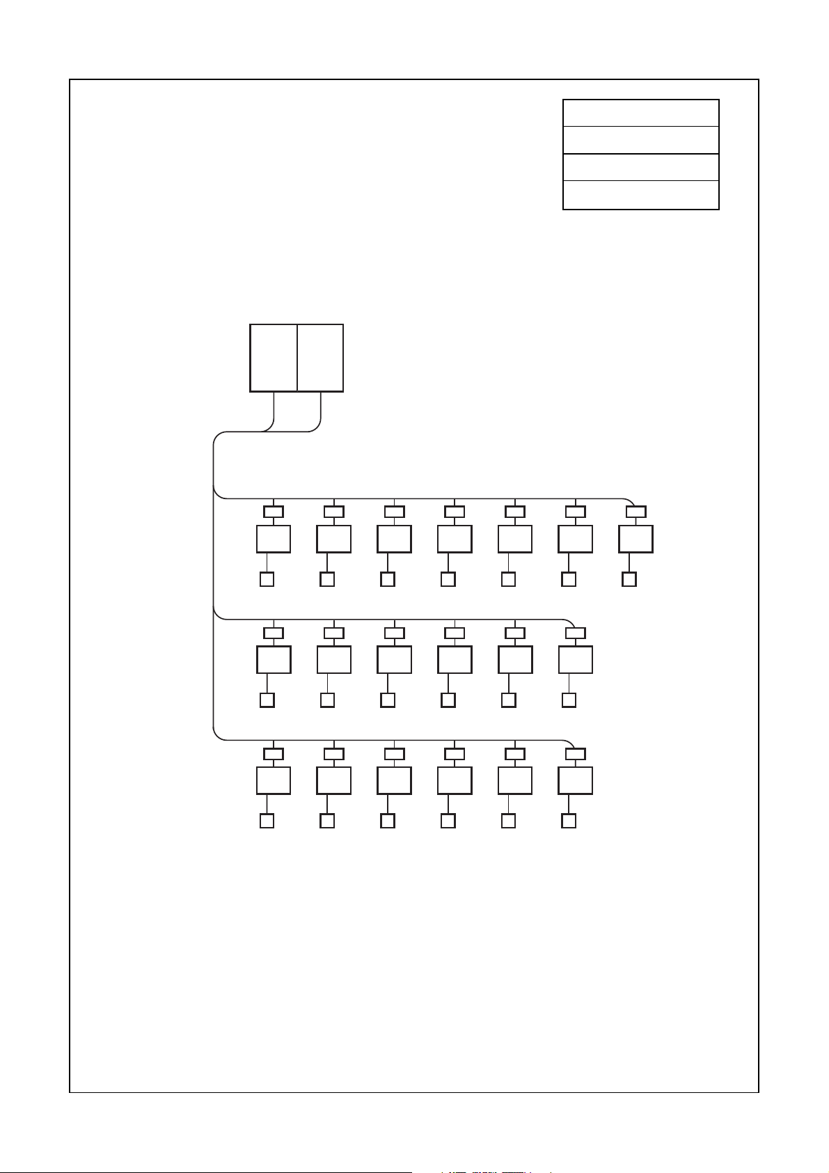
Page 11
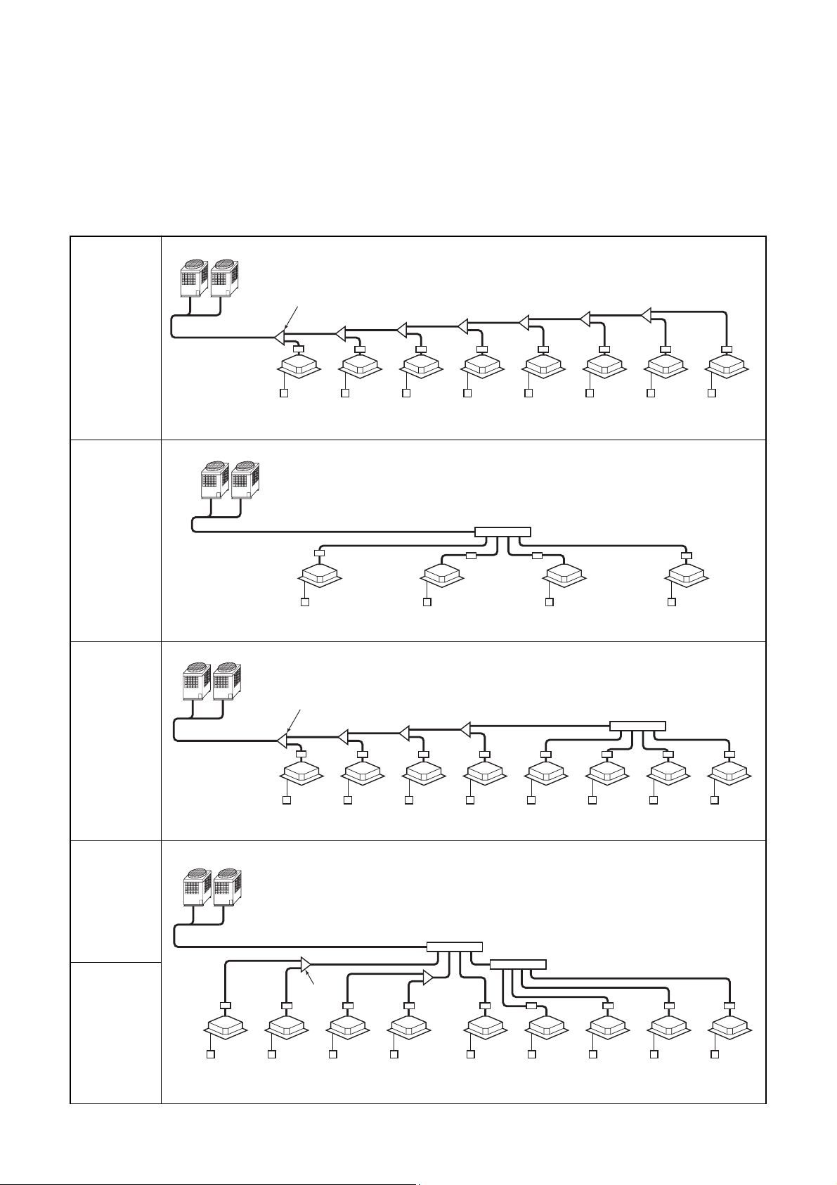
3. BASIC SYSTEM CONFIGURATION
8HP system
• Max. indoor unit : 13 units
• Capacity code of indoor unit : Min. : 5.6
Outdoor unit
8HP
10.4
4.8
007
(0.8)
Max. : 10.8
4.0 3.2 2.4 1.6
007
(0.8)
Capacity code
over the branch
(0.8 + 0.8 = 1.6)
007
(0.8)
007
(0.8)
007
(0.8)
Capacity code
Total 10.4
No. of total units
13
Indoor unit
designation
Capacity
code
007
(0.8)
FS unit
Indoor unit
Remote
controller
5.6 4.8 4.0 3.2 2.4 1.6 0.8
007
(0.8)
007
(0.8)
007
(0.8)
007
(0.8)
007
(0.8)
007
(0.8)
007
(0.8)
11
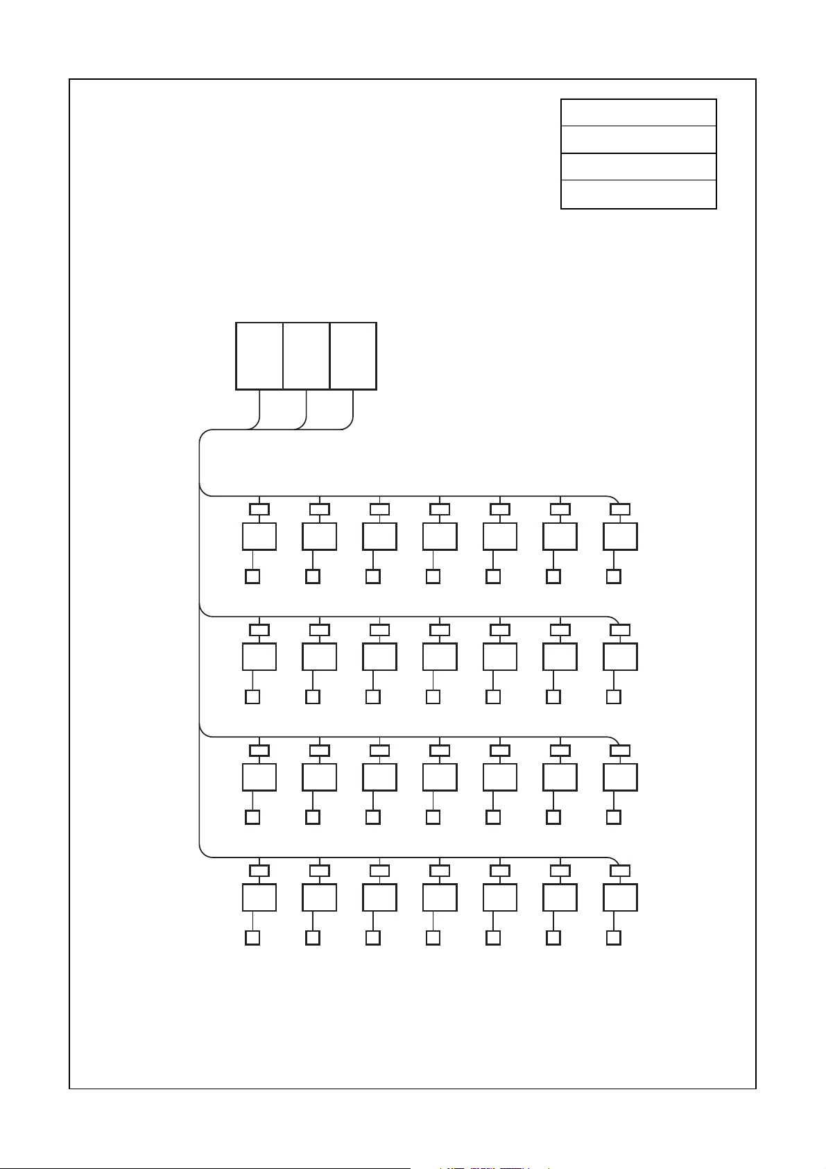
Page 12
10 HP system
• Max. indoor unit : 16 units
• Capacity code of indoor unit : Min. : 7
Outdoor unit
10HP
Max. : 13.5
Capacity code
Total 12.8
No. of total units
16
12.8
FS unit
Indoor unit
Remote
controller
6.4
007
5.6 4.8 4.0 3.2 2.4 1.6
(0.8)
007
(0.8)
007
(0.8)
007
(0.8)
007
(0.8)
007
(0.8)
007
6.4 5.6 4.8 4.0 3.2 2.4 1.6
007
(0.8)
007
(0.8)
007
(0.8)
007
(0.8)
007
(0.8)
007
(0.8)
007
(0.8)
(0.8)
007
(0.8)
007
(0.8)
12
Page 13
12 HP system
• Max. indoor unit : 16 units
• Capacity code of indoor unit : Min. : 8.4
Outdoor unit
12HP
Max. : 14.4
Capacity code
Total 14.0
No. of total units
16
14.0
FS unit
Indoor unit
Remote
controller
6.4
007
5.6 4.8 4.0 3.2 2.4 1.6
(0.8)
007
(0.8)
007
(0.8)
007
(0.8)
007
(0.8)
007
(0.8)
007
7.6 6.8 6.0 5.0 4.0 3.0 2.0
007
(0.8)
007
(0.8)
009
(1.0)
009
(1.0)
009
(1.0)
009
(1.0)
009
(0.8)
(1.0)
007
(0.8)
009
(1.0)
13
Page 14
20 HP system
• Max. indoor unit : 33 units
10
10HP10HP
Max. : 27
• Capacity code of indoor unit : Min. : 14
Outdoor unit
Capacity code
Total 26.75
No. of total units
19
26.75
16.5
FS unit
Indoor unit
Remote
controller
10.25 8.25
018
(2.0)
6.25 5.0 3.75 2.5
018
(2.0)
012
(1.25)
012
(1.25)
8.25 6.25 5.0 3.75 2.5
018
(2.0)
012
(1.25)
012
(1.25)
012
(1.25)
8.25 6.25 5.0 3.75 2.5
018
(2.0)
012
(1.25)
012
(1.25)
012
(1.25)
012
(1.25)
012
(1.25)
012
(1.25)
012
(1.25)
012
(1.25)
012
(1.25)
012
(1.25)
14
Page 15
30 HP system
• Max. indoor unit : 48 units
10HP 10HP10HP
Max. : 40.5
1020
• Capacity code of indoor unit : Min. : 21
Outdoor unit
Capacity code
Total 40
No. of total units
28
40
30
20
FS unit
10 9.2 8.4 7.6 6.8 6
007
(0.8)
007
(0.8)
007
(0.8)
007
(0.8)
007
(0.8)
018
10 9.2 8.4 7.6 6.8 6
007
(0.8)
007
(0.8)
007
(0.8)
007
(0.8)
007
(0.8)
018
10 9.2 8.4 7.6 6.8 6
007
(0.8)
007
(0.8)
007
(0.8)
007
(0.8)
007
(0.8)
018
10 9.2 8.4 7.6 6.8 6
(2)
(2)
(2)
036
(4)
036
(4)
036
(4)
Indoor unit
Remote
controller
007
(0.8)
007
(0.8)
007
(0.8)
15
007
(0.8)
007
(0.8)
018
(2)
036
(4)
Page 16
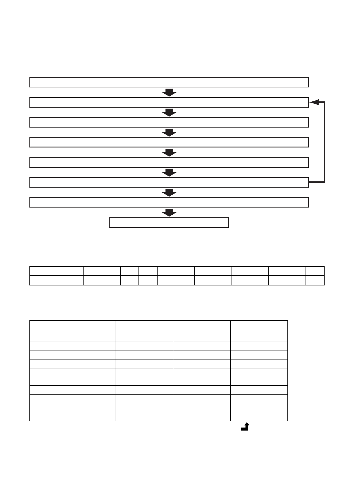
4. EQUIPMENT SELECTION PROCEDURE
1. Selection flow chart
1. Determination of indoor air conditioning load
2. Preliminary selection of indoor units
3. Preliminary selection of outdoor unit with indoor units
4. Capacity correction for piping length/height between indoor and outdoor units
5. Capacity correction based on indoor and outdoor temperature
6. Validate preliminary selection of indoor units
7. Confirmation of selection for indoor unit and outdoor units
NO
End
2. Combination conditions for indoor unit and outdoor unit
1. For indoor unit, the capacity code is decided for each capacity rank.
Capacity rank type
Capacity code
NOTE :
Capacity rank : Correspondence to Btu/h. Capacity code : Correspondence to Horsepower.
2. For outdoor unit, maximum No. of connectable indoor units and total capacity code of indoor units are decided.
Outdoor unit
(Heat recovery)
MMY-MAP0802FT8 8 13 5.6 to 10.8
MMY-MAP1002FT8 10 16 7.0 to 13.5
MMY-MAP1202FT8 12 16 8.4 to 14.4
MMY-AP1602FT8 16 27 11.2 to 21.6
MMY-AP1802FT8 18 30 12.6 to 24.3
MMY-AP2002FT8 20 33 14.0 to 27.0
MMY-AP2402FT8 24 40 16.8 to 32.4
MMY-AP2602FT8 26 43 18.2 to 35.1
MMY-AP2802FT8 28 47 19.6 to 37.8
MMY-AP3002FT8 30 48 21.0 to 40.5
007
0091012
0.8
70 to 135% of outdoor unit capacity for all systems except 12HP
70 to 120% of outdoor unit capacity for 12HP
1.25
Capacity code of
015
1.7
outdoor unit
0182024
2.5
027
3
Max. No. of
indoor units
030
0364048
3.2
Total capacity code
of indoor units
056
5
6
0728096
10
16
Page 17
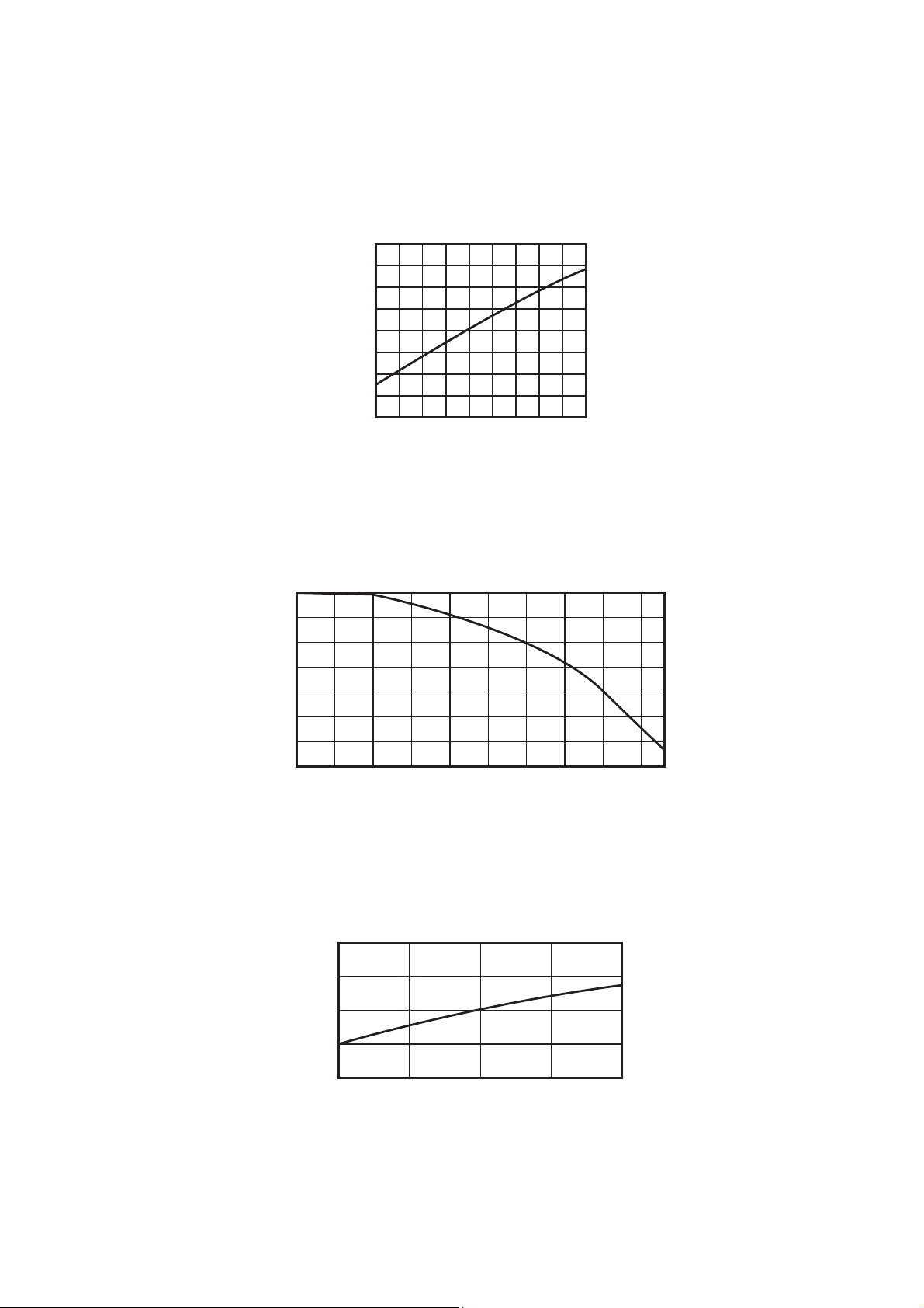
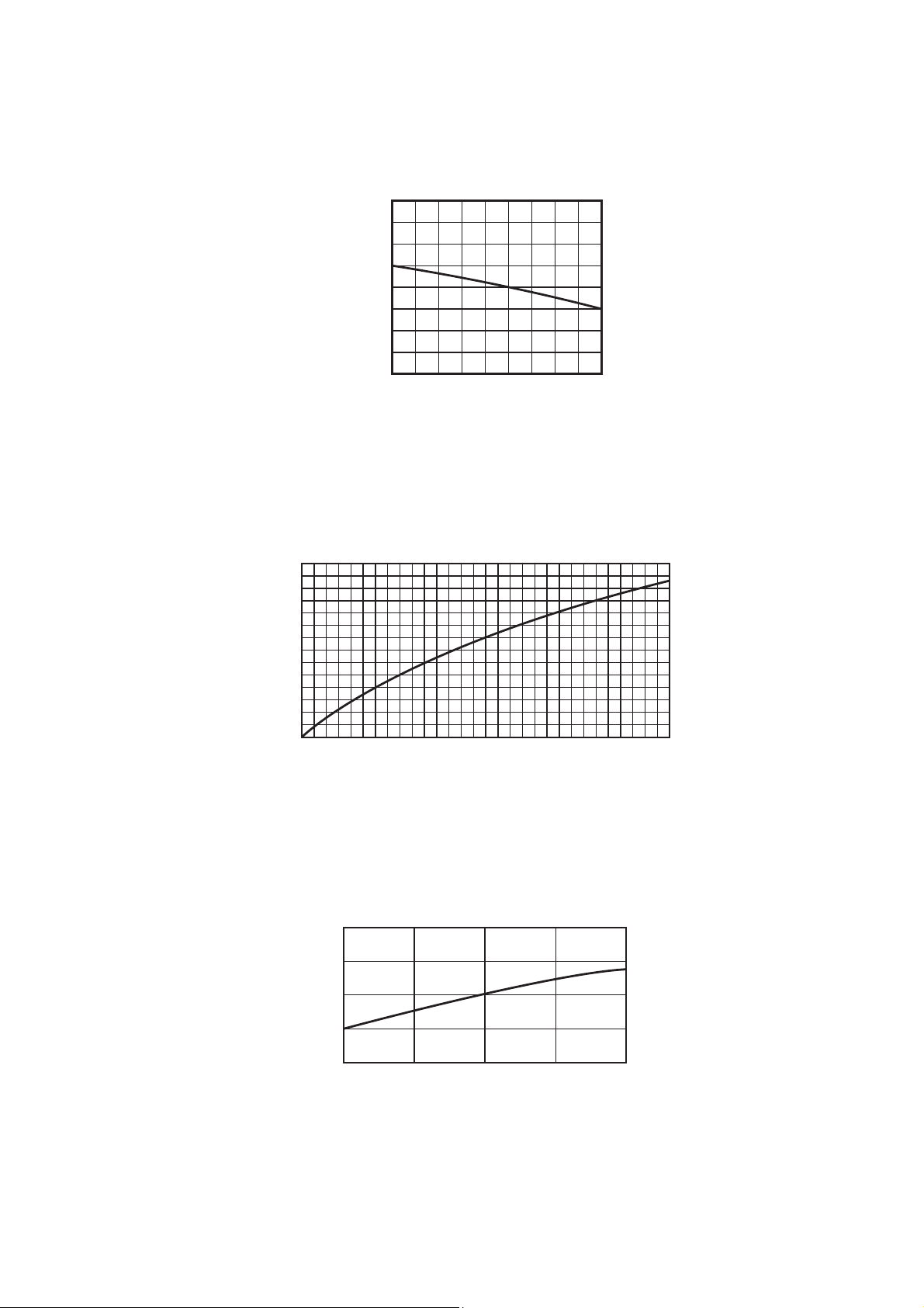
3. Cooling/heating capacity characteristics
1. Cooling capacity calculation method :
Required cooling capacity = Cooling capacity x Factor (
Indoor air wet bulb temperature vs. capacity correction value
1.2
1.1
1.0
0.9
,
,
,
1
,
*
) kW
0.8
Capacity correction value
15
20 24
Indoor air wet bulb temp. (˚C)
Outdoor air dry bulb temperature vs.capacity correction value
1.2
1.1
1.0
0.9
–5 0 5 10 15 20 25 30 35 40 43
Capacity correction value
Outdoor air dry bulb temp. (˚C)
Air flow variation ratio of indoor unit vs. capacity correction (For concealed duct type only)
1.1
1.0
0.9
80 90 100 110 120
Capacity correction value
1 : Coefficient to use for correction of outdoor unit capacity when total capacity of the indoor
*
Air flow variation ratio (%)
units are not equal to the outdoor unit capacity.
17
Page 18
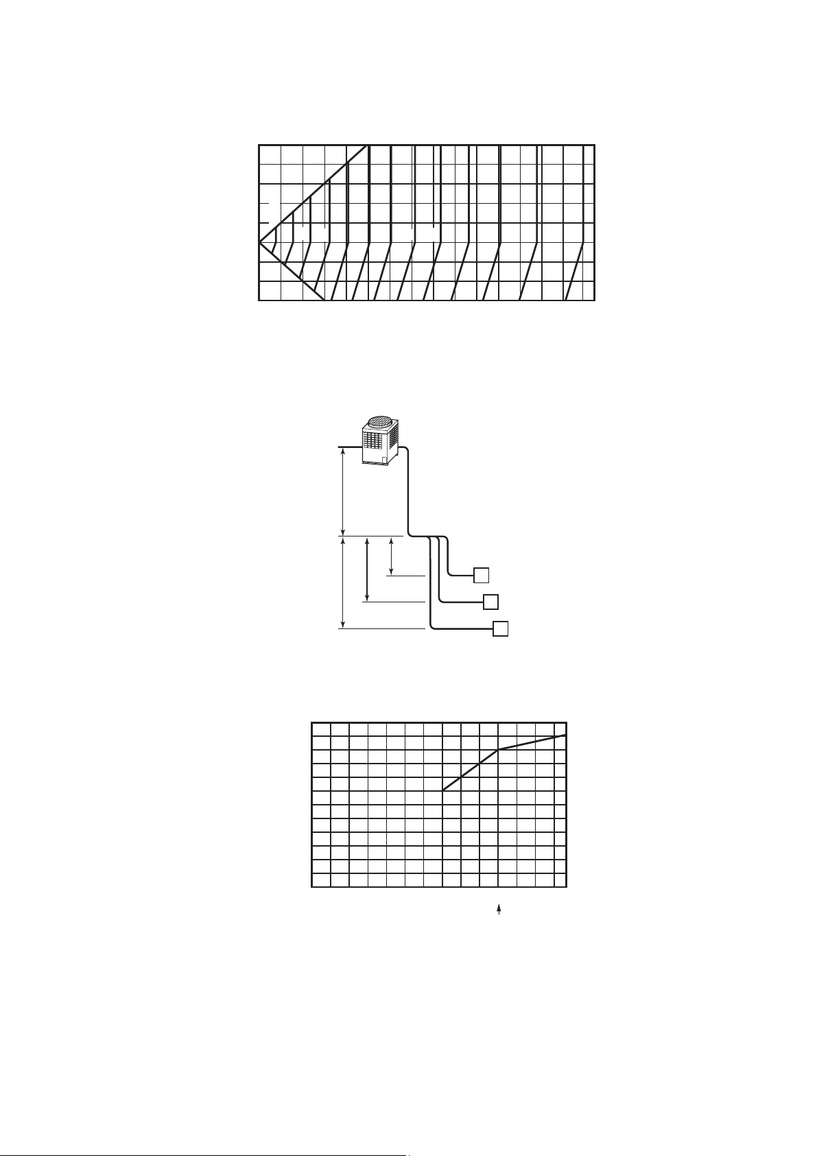
Connecting pipe length and lift difference between indoor and outdoor units vs. capacity correction value
Outdoor unit (8 to 30HP)
50
40
30
20
%100
10
0
–10
–20
–30
Height of outdoor unit H (m)
98
20 30 40 50 60 70 80 90
100
Pipe length (Equivalent length) L (m)
96
92
94
ho l’o
908488
86
Outdoor unit
L’ is the longest one of
(l’o + l’a, l’o + l’b, l’o + l’c)
H = ho +
(Largest one of ha, hb, and hc)
82
80
100 110 120
78
130 140 150
76
Correction of outdoor unit diversity
hb
hc
120
100
80
60
40
Correction (%)
20
0
20 40 60 80 100 120 135
ha
l’a
l’b
l’c
A
B
Standard capacity ratio
Indoor units total capacity ratio (%)
Indoor unit
C
1 : Coefficient to use for correction of outdoor unit capacity when total capacity of the indoor
*
units are not equal to the outdoor unit capacity.
18
Page 19
2. Heating capacity calculation method :
Required heating capacity = Heating capacity x Factor (
Indoor air dry bulb temperature vs. capacity correction value
1.2
1.1
1.0
0.9
0.8
15 20 24
Capacity correction value
Indoor air dry bulb temp. (˚C)
Outdoor air wet bulb temperature vs. capacity correction value
,
,
,
,
*1,
*2) kW
1.2
1.1
1.0
0.9
0.8
0.7
0.6
0.5
–15 –10 –5 0 5 10 15
Capacity correction value
Outdoor air wet bulb temp. (˚C)
Air flow variation ratio of indoor unit vs. capacity correction (For concealed duct type only)
1.1
1.0
0.9
80 90 100 110 120
Capacity correction value
1 : Coefficient to use for correction of outdoor unit capacity when total capacity of the indoor
*
units are not equal to the outdoor unit capacity.
2 : Refer to item 3 in page 20.
*
Air flow variation ratio (%)
19
Page 20
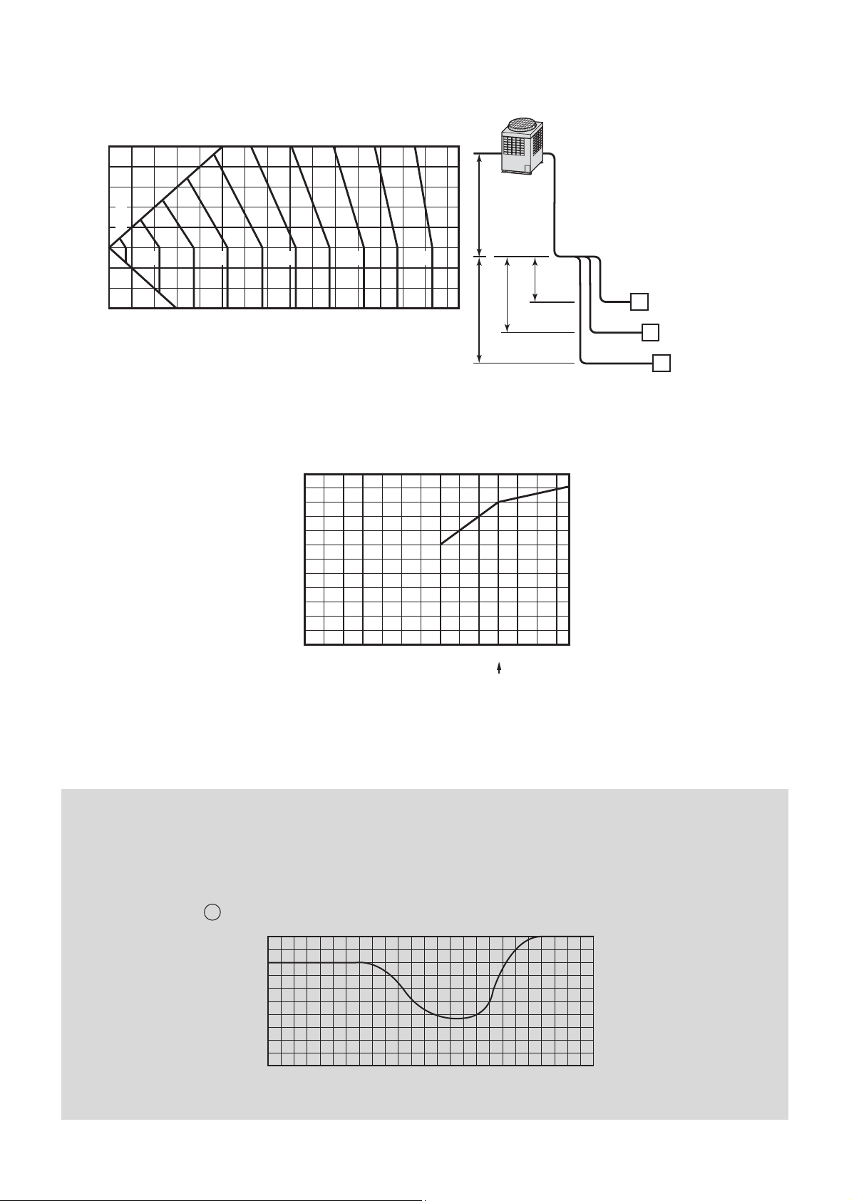
Connecting pipe length and lift difference between indoor and outdoor units vs. capacity correction value
Outdoor unit (8 to 30HP)
50
40
30
20
10
100%
0
–10
–20
–30
Height of outdoor unit H (m)
100 2030405060708090
Pipe length (Equivalent length) L (m)
Correction of outdoor unit diversity
99
98
97
96
120
100
93
94
95
100 110 120 130 140 150
80
92
91
ho l’o
hb
hc
Outdoor unit
L’ is the longest one of
(l’o + l’a, l’o + l’b, l’o + l’c)
H = ho +
(Largest one of ha, hb, and hc)
ha
l’a
A
l’b
B
Indoor unit
l’c
C
60
40
Correction (%)
20
0
20 40 60 80 100 120 135
Standard capacity ratio
Indoor units total capacity ratio (%)
1 : Coefficient to use for correction of outdoor unit capacity when total capacity of the indoor
*
units are not equal to the outdoor unit capacity.
3. Capacity correction in case of frost on the outdoor heat exchanger in heating
Correct the heating capacity when frost was found on the outdoor heat exchanger.
Heating capacity = Capacity after correction of outdoor unit × Correction value of capacity resulted from frost
(Capacity after correction of outdoor unit : Heating capacity calculated in the above item 2.)
6 Capacity correction in case of frost on the outdoor heat exchanger
1.0
0.9
0.8
Capacity correction value
–15 –10 –5 0 5 10
Outdoor air wet bulb temp. (˚C)
20
Page 21
4. Capacity calculation for each indoor unit
Capacity for each indoor unit
= Capacity after correction of outdoor unit ×
5. Operating temperature range
Required standard capacity of indoor unit
Total value of standard indoor unit capacity
45
40
35
30
25
20
15
10
Outdoor air dry bulb temp. (˚C)
–5
–10
In cooling time
Continuously
operable
range
5
0
Indoor air wet bulb temp. (˚C)
Usable range
(in pull down)
Outdoor air wet bulb temp. (˚C)
3025 28201510
In heating time
20
15
10
5
Usable range
(in warming-up)
Continuously
operable
range
0
–5
–10
–15
–20
5 1015202530
Indoor air dry bulb temp. (˚C)
* The unit can be operated even if outdoor temperature gets down to -20°C, however note that the war-
ranty covers only up to -15°C because operation beyond that temperature is out of specification.
* When outdoor air temperature falls to under -15°C, it may cause shortening the product lifetime.
* When outdoor temperature goes out of specified range “ or ” mark is indicated on the remote control-
ler display and required operation will stop.
“ & ”: When heating operation
“ ”: When cooling operation
[Notice]
• This indication is not failure.
• When outdoor temperature goes back to specified range, “ or ” disappear and start normal operation.
• Operation stops because concurrent operation can not be kept in the condition of out of specification
for Super HRM.
(Outdoor temp.(DB) <-10°C: Cooling,
>21°C: Heating)
* Do not use “Super HRM” for other than personal usage where the ambient temperature may go down
below -10°C. (For example, OA equipment/Electric device/Food/Animals and plants/Art object)
6. Rated conditions
Cooling :
Indoor air temperature 27°C DB/19.0°C WB, Outdoor air temperature 35°C DB
Heating :
Indoor air temperature 20°C DB, Outdoor air temperature 7°C DB/6°C WB
21
Page 22
2 – 12 – 22 – 3
1
–
1
1
–
3
1
–
2
1
–
4
2
–
42 – 5
Office rooms
(2–1, 2–2 : Computer room)
Stores
(1-4 : Kitchen)
1F
2F
Non-air conditioning zone
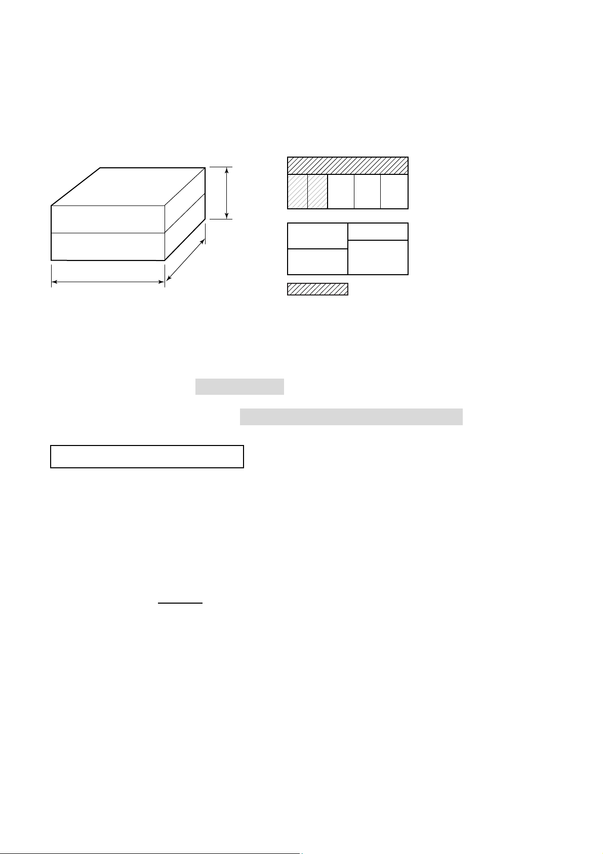
4. Example of equipment selection
The following shows an example of equipment selection based upon a building model
Fig. 1 Overview of building model
<Outside view> <Stories configuration>
8m
2F
1F
7.2m
14.4m
• Steel frame, reinforced concrete building, four stories
above ground. Total floor area : 207m²
Outdoor unit is installed on the roof.
• Design indoor conditions
Cooling : 27.0/19.0°C DB/WB, Heating : 20°C DB
• Design outdoor conditions
Cooling : 35°C DB (Standard condition), Heating : 3°C WB (Standard condition : 6°C WB)
Selection Criteria for Each Floor
2F : Outdoor capacity exactly matches the total indoor capacity.
Total indoor HP = Outdoor unit HP Indoor : 2.5 HP x 2 units + 1.25 HP + 2 HP x 2 = 10.25 HP
Outdoor : 10 HP Same capacity
Heat load of room 2-1 and 2-2 is higher than other rooms.
1F : Consider the increasing heat load in the specific room.
• Total indoor units HP > Outdoor unit HP
• Select each indoor unit based on individual peak room load.
Indoor : 2.5HP + 2.5HP + 3.2HP + 2.0HP =
10.2HP < > Outdoor : 10HP (Same capacity)
• The room “1-4” is designed for “cooling only” because of its high heat load.
• The outdoor module should have sufficient capacity to cover the peak demand of the indoor unit
connected.
22
Page 23
Procedure and result of equipment selection
1. Procedure of equipment selection
a. Calculate cooling for every rooms.
b. Select an indoor unit to match the cooling load for every room from the table in pages 8.
c. Choose a tentative outdoor module that will match with the indoor units. Perform capacity correction
based on the pipe length, system lift, indoor set temperature, outdoor temperature.
Then, make sure the corrected system cooling capacity satisfies the cooling load.
2. Equipment selection and capacity check
Air conditioning load Equipment selection
Indoor unit Outdoor unit
Capacity (kW) Capacity (kW)
Cooling Heating
Model
MMY-
Cooling Heating
Floor Room No.
2-1 6.0 3.4 MMU-AP0241H 7.1 8.0
2-2 5.0 2.2 MMU-AP0181H 5.6 6.3
Indoor air conditioning load
(kW)
Cooling Heating
Model
2F
1F
Floor Room No.
2F
1F
2-3 5.0 4.2 MMU-AP0181H 5.6 6.3
2-4 3.2 2.7 MMU-AP0121H 3.6 4.0
2-5 6.4 5.4 MMU-AP0241H 7.1 8.0
1-1 6.1 6.0 MMU-AP0241H 7.1 8.0
1-2 6.3 6.3 MMU-AP0241H 7.1 8.0
1-3 7.2 7.0 MMU-AP0301H 9.0 10.0
1-4 5.1 — MMD-AP0181H 5.6 6.3
Piping distance Capacity correction Capacity check after correction
2-1 6.6
2-2 5.2 5.5
2-3 5.2
2-4 3.3 3.5
2-5 6.6
1-1 6.6
1-2 6.6
1-3 8.4 8.8
Equivalent
length (m)
34 5
Height
difference
(m)
MAP2002FT8 56.0 63.0
Pipe correction x temp.
correction
Cooling Heating Cooling Heating
1.0
1.0
×
1.0
×
0.936
=
0.936
×
0.95
×
0.98
×
0.95
=
0.884
Capacity
Capacity (kW)
7.0
5.5
7.0
7.0
7.0
Judgment
good
1-4
5.2 5.5
23
Page 24
Schematic diagram
MMY-MAP2002FT8
10 10
Outdoor unit
1st branching joint
2nd branching
joint
3rd branching
joint
4th branching
joint
5th branching
joint
FS unit
RBM-Y1122FE
Indoor unit
MMU-AP0241H
MMU-AP0181H
RR R R R
1
FS unit
RBM-Y1122FE
Computer
Room
Computer
Room
2
–
Indoor unit
MMU-AP0241H
R
Store Store
1 – 11
FS unit
RBM-Y1122FE
Indoor unit
2 – 22
Indoor unit
MMU-AP0241H
FS unit
RBM-Y1122FE
Indoor unit
MMU-AP0181H
Office Office Office
–
32
FS unit
RBM-Y1122FE
R
–
21
FS unit
RBM-Y1122FE
Indoor unit
MMU-AP0121H
–
Branching header
FS unit
RBM-Y1122FE
Indoor unit
MMU-AP0301H
R
Restaurant
FS unit
RBM-Y1122FE
Indoor unit
MMU-AP0241H
42
–
5
Indoor unit
MMD-AP0181H
R
<Cooling only>
Kitchen
–
31
–
4
24
Page 25
5. REFRIGERANT PIPING DESIGN
1. Warnings on refrigerant leakage Important
Check of Concentration Limit
The room in which the air conditioner is to be installed requires a design that in the event of refrigerant gas leaking out, its concentration will not exceed
a set limit.
The refrigerant R410A which is used in the air conditioner
is safe, without the toxicity or combustibility of ammonia,
and is not restricted by laws to be imposed which protect
the ozone layer. However, since it contains more than air,
it poses the risk of suffocation if its concentration should
rise excessively. Suffocation from leakage of R410A is
almost non-existent. With the recent increase in the
number of high concentration buildings, however, the
installation of multi air conditioner systems is on the
increase because of the need for effective use of floor
space, individual control, energy conservation by curtailing heat and carrying power etc.
Most importantly, the multi air conditioner system is able
to replenish a large amount of refrigerant compared with
conventional individual air conditioners. If a single unit of
the multi conditioner system is to be installed in a small
room, select a suitable model and installation procedure
so that if the refrigerant accidentally leaks out, its
concentration does not reach the limit (and in the event of
an emergency, measures can be made before injury can
occur).
In a room where the concentration may exceed the limit,
create an opening with adjacent rooms, or install mechanical ventilation combined with a gas leak detection
device.
The concentration is as given below.
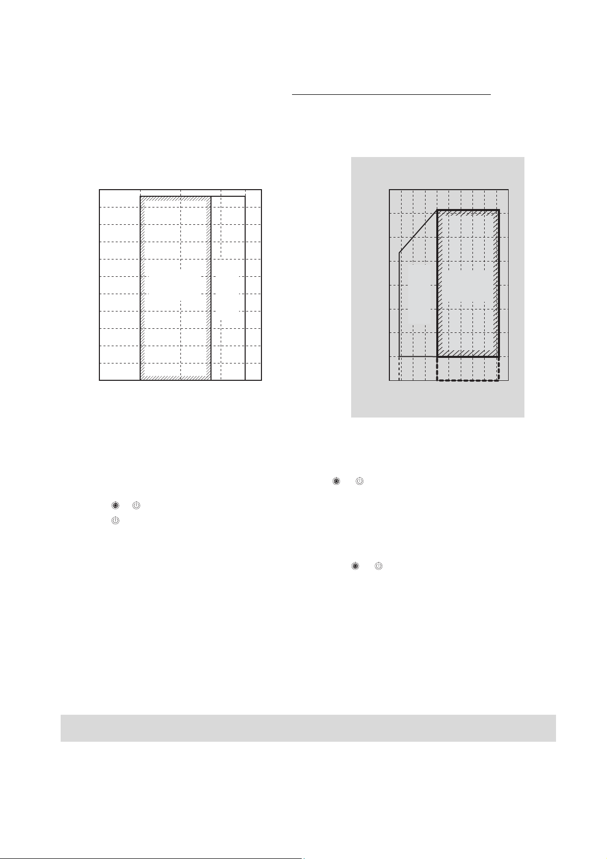
NOTE 2 :
The standards for minimum room volume are as follows.
(1) No partition (shaded portion)
(2) When there is an effective opening with the adjacent
room for ventilation of leaking refrigerant gas
(opening without a door, or an opening 0.15% or
larger than the respective floor spaces at the top or
bottom of the door).
Outdoor unit
Refrigerant piping
Indoor unit
(3) If an indoor unit is installed in each partitioned room
and the refrigerant tubing is interconnected, the
smallest room of course becomes the object. But
when a mechanical ventilation is installed interlocked
with a gas leakage detector in the smallest room
where the density limit is exceeded, the volume of the
next smallest room becomes the object.
Refrigerant piping
Total amount of refrigerant (kg)
Min. volume of the indoor unit installed room (m³)
≤
Concentration limit (kg/m³)
The concentration limit of R410A which is used in multi
air conditioners is 0.3kg/m³.
(For details, refer and comply with local regulations.)
NOTE 1 :
If there are 2 or more refrigerating systems in a single
refrigerating device, the amounts of refrigerant should be
as charged in each independent device.
e.g., charged
amount (10kg)
Room A Room B Room C Room D Room E Room F
For the amount of charge in this example:
The possible amount of leaked refrigerant gas in rooms
A, B and C is 10kg.
The possible amount of leaked refrigerant gas in rooms
D, E and F is 15kg.
Outdoor unit
e.g.,
charged amount (15kg)
Indoor unit
Outdoor unit
Ver y
small
room
Small
room
Mechanical ventilation device - Gas leak detector
Medium
room
Large room
Indoor unit
NOTE 3 :
The minimum indoor floor area compared with the
amount of refrigerant is roughly as follows:
(When the ceiling is 2.7m high)
40
Range below the
35
m²
density limit
of 0.3 kg/m³
30
(countermeasures
not needed)
25
20
15
10
5
Min. indoor floor area
0
10 20 30
Total amount of refrigerant
Range above
the density limit
of 0.3 kg/m³
(countermeasures
needed)
kg
25
Page 26
2. Free branching system
Line branching system
Header branching system
Header branching system after line branching
Line branching system after header branching
Header branching system after header branching
The above five branching systems are available to dramatically increase the flexibility of refrigerant piping design.
Outdoor unit
Branching joint
Line
branching
system
FS unit
Indoor unit
Remote
controller
Outdoor unit
Header
branching
system
Header
branching
system
after line
branching
Line
branching
system after
header
branching
Indoor unit
Outdoor unit
FS unit
Indoor unit
Outdoor unit
FS unit
Branching joint
Remote
controller
Branching header
Remote controller
Branching header
Branching header
Header
branching
system after
header
branching
FS unit
Indoor
unit
Remote
controller
Branching
joint
26
Page 27
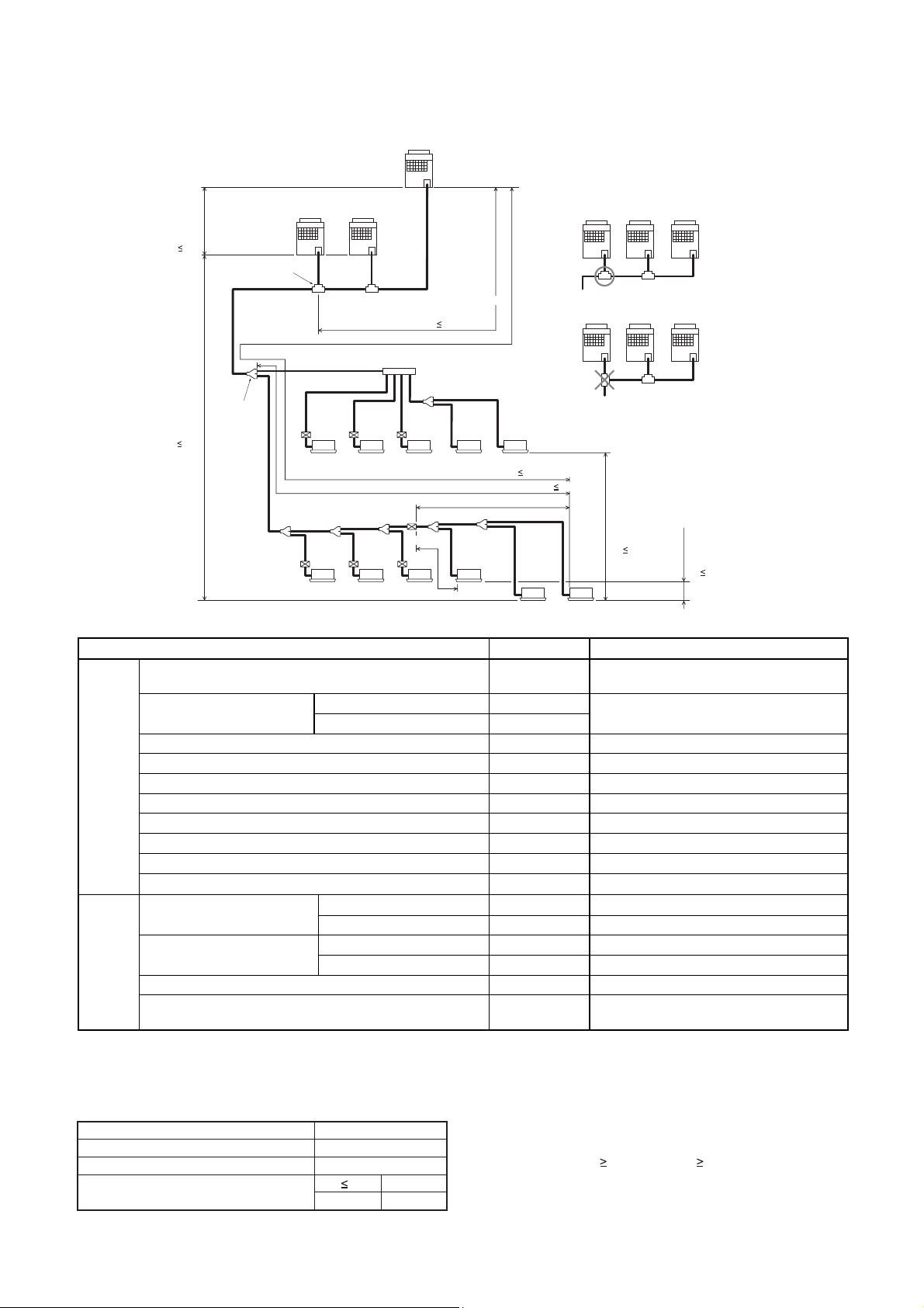
g
3. Allowable length/height difference of refrigerant piping
Height
difference
between
outdoor
units
H3 5m
Height
difference
between
outdoor
and indoor
units
H1 50m
Outdoor Unit
T-shape
branching
Main piping
L1
1st branching
section
Follower Unit
C
Header Unit
Branching piping
Connecting piping of
indoor unit
L3
Equivalent length corresponded to farthest piping after 1st branching Li 50m
FS unit
Follower Unit
A
a
ghi j
Indoor unit
Equivalent length corresponded to farthest piping L 150m
L4 L5 L6 L7LhL8
def
lmn
Indoor unit
B
La Lb Lc
LA
Main connecting piping between outdoor units
Length corresponded to farthest piping
between outdoor units LO 25m
Branching
header
L2
L9
bc
FS unit
< Cooling only >
FS unit
k
o
(Header)
< Cooling only >
Lj
pq
Note:
In case of connecting method <Ex.2>, a large
amount of refrigerant and refrigerant oil may
return to the head unit. Therefore, set the T-shape
joint so that oil does not enter directly.
<Ex.1>
Header UnitAFollower UnitBFollower Unit
<Ex.2>
Header UnitAFollower UnitBFollower Unit
Height difference
between
indoor
units
H2 35m
(Upper outdoor unit)
(q)
C
C
Height difference
between indoor units
in group control by
one FS unit
H4 0.5 m
* Allowable length and height difference of refrigerant piping
Allowable value Piping section
Total extension of pipe (Liquid pipe, real length) 300 m
Farthest piping length L (*1)
Real length 125 m
Equivalent length 150 m
LA+La+Lb+Lc+L1+L2+L3+L4+L5+L6+L7+L8+9
+a+b+c+d+e+f+g+h+i+j+k+l+m+n+o+p+q
LA+Lc+L1+L3+L4+L5+L6+L7+L8+q
Max. equivalent length of main piping 85 m L1
Equivalent length of farthest piping from 1st branching Li (*1) 50 m L3+L4+L5+L6+L7+L8+q
Pipe
Length
Max. real length of indoor unit connecting piping 30 m a+g, b+h, c+i, d+l, e+m, f+n, j, k
Max. real length between FS unit and indoor unit (*2) 15 m g, h, i, l, m, n, L7+o, L7+L8+p, L7+L8+q
Max. Equivalent length of outdoor unit connecting piping LO (*1) 25 m LA+Lc (LA+Lb)
Max. real length of outdoor unit connecting piping 10 m La, Lb, Lc
30 m
15 m
50 m
L7+L8+q, L7+L8+p
L7+o
——
Height
Difference
Max. equivalent length between FS unit and indoor unit Lj
Max. real length between FS unit and header indoor unit Lh (
Height between indoor
and outdoor units H1
Upper outdoor unit
Lower outdoor unit 30 m ——
Upper outdoor unit 35 m ——
Height between indoor units H2
Lower outdoor unit 15 m ——
2)
*
Height between outdoor units H3 5 m ——
Hei
ht difference between indoor units in group control by one FS
unit H4
1 : The farthest outdoor unit from 1st branch to be named C, and farthest indoor unit from 1st branch to be named (q).
*
2 : Attached connection cable can be used up to 5 m in pipe length between indoor and FS unit. When the pipe length
*
between indoor and FS unit exceeds 5 m, be sure to use the connection cable kit (RBC-CBK15FE).
* System restrictions
Max. No. of combined outdoor units
Max. capacity of combined outdoor units
Max. No. of connected indoor units
Max. capacity of combined indoor units
1 : MMY-MAP1201HT8 : UP to 120 %
*
84.0 kW
48 units
H2 15m
H2
>
15m
3 units
135% (*1)
105%
Note 1) Combination of outdoor units : Header unit (1 unit) +
Note 2) Install the outdoor units in order of capacity.
Note 3) Refer to outdoor unit combination table in page.6.
Note 4) Piping to indoor units shall be perpendicular to piping to
0.5 m ——
Follower unit (0 to 2 units). Header unit is outdoor unit
nearest to the connected indoor units
(Header unit Follower unit 1 Follower unit 2)
the head outdoor unit as <Ex.1>.
Do not connect piping to indoor units in the same
direction of head outdoor unit as <Ex.2>.
27
Page 28
Y
yp
yp
yp
g
g
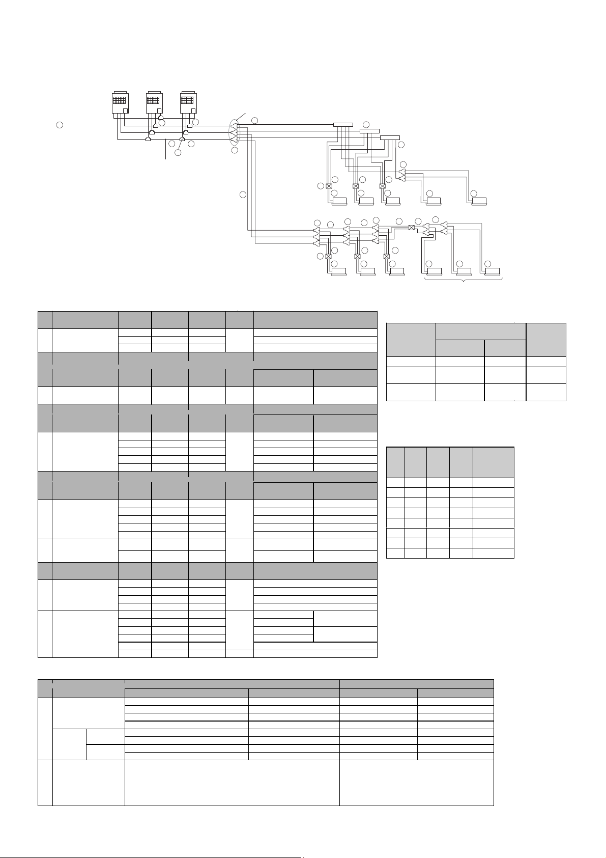
4. Selection of refrigerant piping
Follower UnitCFollower UnitBHeader Unit
A
Outdoor unit
Balance pipe
2
9
T-shape
branching joint
1
Main piping
3
Outdoor unit
1
connecting piping
1
Main connecting piping
between outdoor units
* Selection of refrigerant piping
No. Item
Pipe size of outdoor
No. Item
No. Item
Size of main pipe
No. Item
No. Item
Piping of i ndoor unit
unit
Connecting pipe size
between outdoor units
Pipe size between
branching sections
*1 *2 *3
Pipe size between the
end of branch and FS
unit
Piping of cooling only
indoor unit (Between
branching and indoor
unit) *2
Suction
gas side
Suction
gas side
Suction
gas side
Suction
gas side
Suction
gas side
Discharge
Ø 9.5
Ø 9.5
gas side
Discharge
gas side
Discharge
gas side
Discharge
gas side
Discharge
gas side
Ø 22.2 Ø 19.1 Ø 12.7 MMY-MAP0802FT8
Ø 22.2 Ø 19.1 Ø 12.7 MMY-MAP1002FT8
Ø 28.6 Ø 19.1 Ø 12.7
Ø 28.6 Ø 22.2 Ø 15.9 Ø 9.5 Below 61.5 Below 22
Ø 22.2 Ø 19.1 Ø 12.7 Below 33.5 Below 12
Ø 28.6 Ø 19.1 Ø 12.7 33.5 12
Ø 28.6 Ø 22.2 Ø 19.1 45.0 to below 61.5 16 to below 22
Ø 34.9 Ø 28.6 Ø 19.1 61.5 to below 73.0 22 to below 26
Ø 34.9 Ø 28.6 Ø 22.2
Ø 15.9 Ø 12.7 Ø 9.5 Below 18.0 Below 6.4
Ø 22.2 Ø 19.1 Ø 12.7 18.0 to below 34.0 6.4 to below 12.2
Ø 28.6 Ø 22.2 Ø 15.9 34.0 to below 56.5 12.2 to below 20.2
Ø 34.9 Ø 28.6 Ø 15.9 56.5 to below 70.5 20.2 to below 25.2
Ø 34.9 Ø 28.6 Ø 19.1
Ø 15.9 Ø 12.7 Ø 9.5 Below 18.0 Below 6.4
Ø 22.2 Ø 19.1 Ø 12.7
Ø 12.7
Ø 15.9
Ø 22.2
Ø 12.7
Ø 12.7
Ø 15.9
Ø 15.9
Ø 22.2
Liquid side Outdoor unit model name
Liquid side
Liquid side
Liquid side
Liquid side Capacity rank of indoor unit
—
—
—
—
—
—
—
—
Ø 6.4 007 to 012 Type
Ø 6.4 015 to 018 Type
Ø 9.5 024 to 056 Type
Ø 12.7
Ø 6.4 15m or less
Ø 9.5 15m above
Ø 6.4 15m or less
Ø 9.5 15m above
Ø 9.5
Ø 12.7
* Selection for branching section
No.
Y-Shape branching joint
*4 *5
Branching
Header
*4, *5, *6
T-Shape branching joint
(For connecting outdoor
unit)
For
4 Branchin
For
8 Branchin
40.0 to below 70.5 14.2 to below 25.2 RBM-HY2043FE RBM-HY2043E
40.0 to below 70.5 14.2 to below 25.2 RBM-HY2083FE RBM-HY2083E
1 set of 4 types of T-shape joint pipes as described below : The rewired
quantity is arranged and combined at the site.
- Balance pipe (Ø 9.52) X 1
- Piping at liquid side (Ø 12.7 to Ø 22.2) X 1
- Piping at discharge gas side (Ø 19.1 to Ø 28.6) X 1
- Piping at suction gas side (Ø 22.2 to Ø 38.1) X 1
Total capacity code of indoor unit Model Name
Equivalent to capacity Equivalent to HP For 3 piping For 2 piping
Below 18.0 Below 6.4 RBM-BY53FE RBM -BY53E
18.0 to below 40.0 6.4 to below 14.2 RBM-BY103FE RBM-BY103E
40.0 to below 70.5 14.2 to below 25.2 RBM-BY203FE RBM-BY203E
70.5 or more 25.2 or more RBM-BY303FE RBM-BY303E
Below 40.0 Below 14.2 RBM-HY1043FE RBM-HY1043E
Below 40.0 Below 14.2 RBM-HY1083FE RBM-HY1083E
1st branching section
Liquid pipe
4
Discharge gas pipe
Suction gas pipe
8
4
Liquid pipe
Discharge gas pipe
Suction gas pipe
—
Balance
pipe
Total capacity code of all outdoor units
MM
Total capacity code of indoor units at
Equivalent to
capacity
Equivalent to
capacity
-MAP1202FT8
downstream side
—
73.0 or more 26 or more
Total capacity code of all indoor units
Equivalent to
capacity
—
70.5 or more 25.2 or more
—
18.0 or more 6.4 or more
—
072 to 096 T
—
— 072 to 096 T
024 to 056 T
5 5 5
10
FS unit
6
8
8
4
5
10
FS unit
6
Indoor unit
Equival ent to HP
Equival ent to HP
Equival ent to HP
e
007 to 012 Type
015 to 018 Type
e
e
Y-Shape branching joint
8
4
Y-Shape branching joint
8
6 6
8
4
5 5
6 6 6 6 6
7 7
< Cooling only >
4
4 4
Group control
< Cooling only >
Selection of FS unit
Total capacity code of
Model Name
RBM-Y1122FE Below 11.2 Below 4.0 5
RBM-Y1802FE
RBM-Y2802FE
* Minimum wall
thickness for R410A
application
Half
Outer
Hard
Soft
OK OK 1/4” 6.35 0.80
OK OK 3/8” 9.52 0.80
OK OK 1/2” 12.70 0.80
OK OK 5/8” 15.88 1.00
NG OK 3/4” 19.05 1.00
NG OK 7/8” 22.20 1.00
NG OK 1.1/8” 28.58 1.00
NG OK 1.3/8” 34.92 1.10
*1 In case the pipe exceeds main pipe size, it
*2 2 pipes for cooling only indoor unit shall be
*3 2 pipes from FS unit to branching section shall
*4 Branching pipe on the 1st branch should be
*5 In case total capacity code for indoor units shall
*6 For 1 line after header branching, indoor units
RBM-BT13FE
dia.
or
(Inch)
Hard
should be the same as main pipe size.
used with liquid pipe and suction gas pipe.
be used with liquid pipe and suction gas pipe.
selected according to the capacity code for
outdoor unit.
be exceeded to capacity code for outdoor unit,
the pipe size should be selected with capacity
code for outdoor unit.
with a maximum of 6.0 capacity code in total
can be connected.
indoor unit
Equivalent to
capacity (kW)
11.2 to below
18.0
18.0 to 28.0
or less
Outer
dia.
(mm)
Minimum
Thickness
Equivalent
to HP
4.0 to below
6.4
6.4 to 10.0
or less
Wall
(mm)
Max.No. of
connected
indoor
units
8
8
28
Page 29
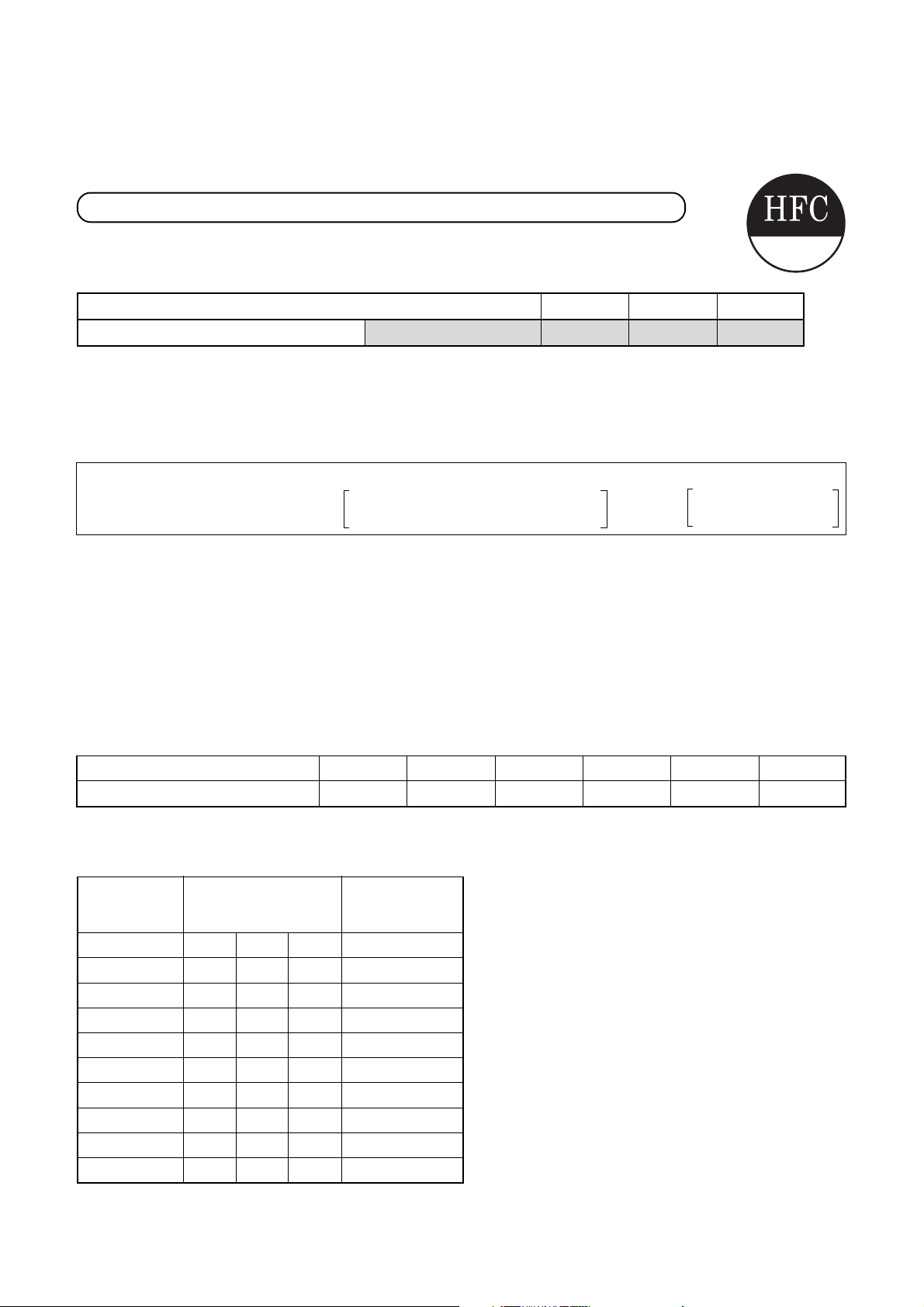
5. Charging requirement with additional refrigerant
After the system has been vacuumed, replace the vacuum pump with a refrigerant cylinder and charge the
system with additional refrigerant.
Calculating the amount of additional refrigerant required
Refrigerant in the system when shipped from the factory
R410A
8HP 10HP 12HP
Refrigerant amount charged in factory
11.5kg 11.5kg 11.5kgHeat recovery model
When the system is charged with refrigerant at the factory, the amount of refrigerant needed for the pipes at the
site is not included. Calculate the additional amount needed, and add that amount to the system.
(Calculation)
Additional refrigerant charge amount is calculated from size of liquid pipe at site and its real length.
[Additional refrigerant charge amount at site] =
[Real length of liquid pipe] ×
Additional refrigerant charge amount
per liquid pipe 1m (Table 1) system HP (Table 2)
× 1.3
+Compensation by
Example : Additional charge amount R (kg) = {(L1 x 0.025kg/m) + (L2 x 0.055kg/m) + (L3 x 0.105kg/m)
+ (L4 x 0.160kg/m) + (L5 x 0.250kg/m)} x 1.3
L1 : Real total length of liquid pipe Ø6.4 (m)
L2 : Real total length of liquid pipe Ø9.5 (m)
L3 : Real total length of liquid pipe Ø12.7 (m)
L4 : Real total length of liquid pipe Ø15.9 (m)
L5 : Real total length of liquid pipe Ø19.1 (m)
System : 24HP
Table 1
Pipe dia. at liquid side
Additional refrigerant amount/1m
Table 2
Combined
horse power
(HP)
8 8 2.0
10 10 2.5
12 12 3.0
16 8 8 -1.5
18 10 8 0.0
20 10 10 2.0
24 8 8 8 -4.5
26 10 8 8 -3.0
28 10 10 8 -1.5
30 10 10 10 0.0
Outdoor
combination (HP)
Ø6.4 Ø9.5 Ø12.7 Ø15.9 Ø19.1 Ø22.2
0.025kg 0.055kg 0.105kg 0.160kg 0.250kg 0.350kg
Compensation
by system HP
(kg)
29
Page 30
6. WIRING DESIGN
1. General
(1) Perform wiring of the power supply in conformance with the regulations of the local electric company.
(2) For the control wires connecting indoor units, and between indoor and outdoor units, use of double-core shield
wires is recommended to prevent noise trouble.
(3) Be sure to set the earth leakage breaker and the switches to the power supply section of the indoor unit.
(4) Supply power to each outdoor unit and provide an earth leakage breaker or hand switch for each outdoor unit.
(5) Never connect the 220–240V power to the terminal block (U1, U2, U3, U4, U5, U6) for control cables.
(Trouble is caused.)
(6) Store wiring system for control and refrigerant piping system in the same line.
(7) Arrange the cables so that the electric wires do not come to contact with high-temperature part of the pipe ;
otherwise coating melts and an accident may be caused.
(8) Do not turn on power of the indoor unit until vacuuming of the refrigerant pipe will finish.
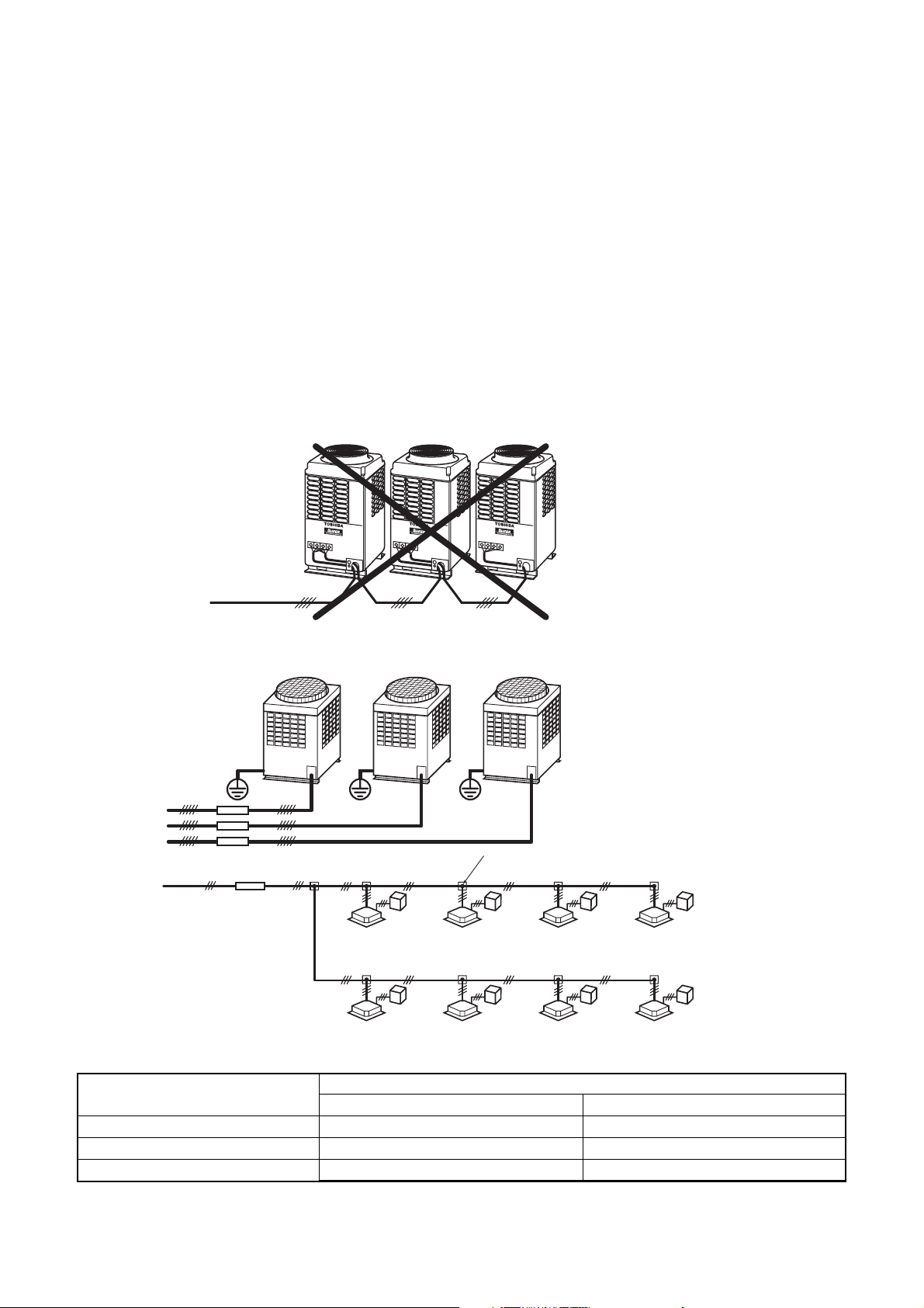
2. For outdoor unit power supply
• Select the power supply cabling and fuse of each outdoor unit from the following specifications:
Cable 5-core, in conformance with Design 60245 IEC 66
• Do not connect them via the incorporated terminal block (L1, L2, L3, N).
L1
L2
L3
N
Outdoor power supply
3-phase 380-415V, 50Hz
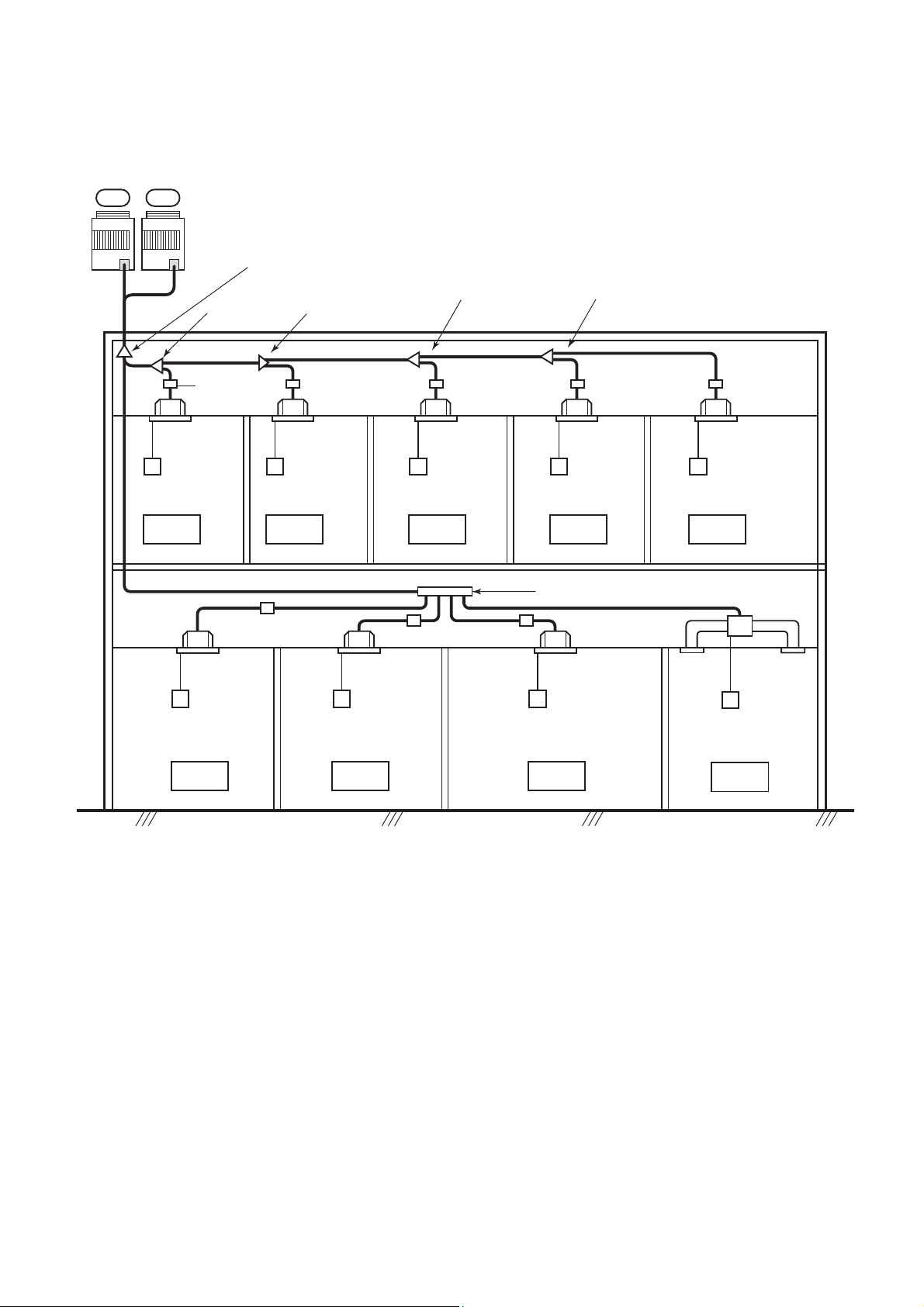
3. Electrical wiring design
3-phase
50Hz 380-415V
Earth leakage breaker
hand switch
Outdoor
power source
Indoor
power source
Earth
Single phase
50Hz 220-240V
Earth leakage breaker
power switch
FS unit
Indoor unit
FS unit
L1
L2
L3
N
L1
L2
FS unit
Indoor unit
FS unit
L3
N
Pull box
FS unit
Indoor unit
FS unit
FS unit
Indoor unit
FS unit
Indoor unit
Indoor unit
Indoor unit
Indoor unit
• Unit capacities and power supply wire sizes (Reference)
Model
MMY-
MAP0802FT8
MAP1002FT8
MAP1202FT8
Wire size
3.5 mm² (AWG #10) Max. 20 m
5.5 mm² (AWG #10) Max. 28 m
5.5 mm² (AWG #10) Max. 27 m
Power supply wiring
Field fuse
30 A
30 A
30 A
• Determine the wire size for indoor unit according to the number of connected indoor units downstream.
• Observe local regulation regarding wire size selection and installation.
30
Page 31

4.
For Indoor unit power supply (Must be independent from outdoor unit power.)
Item
Model
Power supply wiring
Wire size
Field fuse
All models of indoor units 2.0mm² (AWG#14) Max. 20m 3.5mm² (AWG#12) Max. 50m 15A
FS unit
NOTE :
Be sure to use the attached cable. If the length between indoor and FS unit exceeds 5 m,
connect by using the connection cable kit (RBC-CBK15FE). (Sold separately)
The connecting length indicated in the table represents the length from the pull box to the outdoor unit when the indoor
units are connected in parallel for power, as shown in the above illustration. A voltage drop of no more than 2% is also
assumed. If the connecting length will exceed the length indicated in the table, select the wire thickness in accordance
with local wiring standards.
CAUTIONS
(1) Keep the refrigerant piping system and the indoor-indoor/indoor-outdoor control wiring systems together.
(2) When running power wires and control wires parallel to each other, either run them through separate conduits, or
maintain a suitable distance between them.
(Current capacity of power wires: 10A or less for 300m, 50A or less for 500m)
5. Design of control wiring
Power supply
Single phase
220-240V 50Hz
(Open)
Earth
[Central remote controller] (Option)
TCB-SC642TLE (For line 64)
Remote
controller
FS unit
Transmission wire for control
between outdoor units
Transmission wire for control
Transmission wire for control
between outdoor unit and
between outdoor unit and
indoor unit
indoor unit
FS unitFS unit
(Header) (Follower)
FS unit FS unit
Connection of shield wire must be connected
(Connected to all connecting sections in each outdoor unit)
Connection of shield wire must be connected
Connection of shield wire must be connected
(Connected to all connecting sections in each indoor unit)
(Connected to all connecting sections in each indoor unit)
Transmission wire for
control between indoor
and FS unit.
FS unit
Transmission wire for
control between indoor
and FS unit.
FS unit
• Wire specification, quantity, size of crossover wiring and remote controller wiring
Name
Crossover wiring
(indoor-indoor / indoor-outdoor / control wiring,
central control wiring)
Remote controller wiring
Control wiring between indoor and FS unit
Q’ty
2 cores
2 cores
Be sure to use the attached connection cable. If the length between indoor and FS unit
exceeds 5 m, connect by using the connection cable kit (RBC-CBK15FE). (Sold separately)
Up to 500m Up to 1000m 1000 to 2000m
1.25mm
0.5 to 2.0mm
2
Size
2
——
2.0mm
2
Specification
Shield wire
—
(1) The crossover wiring and central control wiring use 2-core non-polarity transmission wires. Use 2-core shield wires to
prevent noise trouble. In this case, close (connect) the end of shield wires, and perform the functional grounding for
the end of the shield wires which are connected to both indoor and outdoor units. For the shield wires which are
connected between the central remote controller and the outdoor unit, perform the functional grounding at only one
end of central control wiring.
(2) Use 2-core and non-polarity wire for remote controller. (A, B terminals)
Use 2-core and non-polarity wire for wiring of group control. (A, B terminals)
31
Page 32

6.
System Wiring Design
Outdoor unit
Outdoor side
Indoor side
Power supply
3 phase 380-415V 50Hz
Earth leakage breaker
Power swith
Earth
terminal
U1
U2 U3 U4 U5 U6
Earth
terminal
Power supply
3 phase 380-415V 50Hz
Earth
terminal
U1 U2 U3 U4 U5 U6
Earth leakage breaker
Power swith
Earth
terminal
Earth
terminal
U1/U3
U2/U4
Central remote
Earth
terminal
controller
Power supply
3 phase 380-415V 50Hz
Earth leakage breaker
Power swith
Earth
terminal
U1 U2 U3 U4 U5 U6
Single phase
220-240V 50Hz
Earth
terminal
Earth
terminal
Power supply
Single phase
220-240V
50Hz
Earth leakage
breaker
Power switch
U1/U2
Earth terminal
LN
Earth
terminal
Pull
Box
Indoor unit
A
B
Control
wiring
Powe r
line
Remote
controller
A
B
FS unit
CN02
CN01
Earth
terminal
U1/U2
Earth terminal
LN
terminal
Pull
Box
Indoor unit
CN81
Earth
Remote
controller
line
A
B
FS unit
CN02
CN01
Earth
terminal
U1/U2
Earth terminal
LN
A
B
Control
wiring
Powe r
Indoor unit
Earth
terminal
A
B
Control
wiring
Powe r
line
Remote
controller
FS unit
NOTE :
Control wire and power line wire between FS unit and indoor unit are the accessary parts of FS unit. (Wire length : 6m)
If the length between indoor and FS unit exceeds 5m, connect by using the connection cable kit sold separately (RBCCBK15FE).
A
B
CN02
CN01
Earth
terminal
32
Page 33

7.
Design
■ Indoor unit
Type Model
4-Way Air
Discharge
Cassette Type
2-Way Air
Discharge
Cassette Type
1-Way Air
Discharge
Cassette Type
Concealed Duct Type
Concealed Duct
High Static
Pressure Type
Under Ceiling Type
High Wall Type (1 series)
High Wall Type (2 series)
Floor Standing
Cabinet Type
Floor Standing
Concealed Type
Floor Standing Type
Legend MCA : Minimum Circuit Amps FLA : Full Load Amps
50Hz
Nominal Volta ge Voltage Range Fan Motor Power Supply
(V-Ph-Hz) Min Max kW FLA MCA MOCP
MMU-AP0091H 230-1-50 198 264 0.060 0.20 0.25 15
MMU-AP0121H 230-1-50 198 264 0.060 0.20 0.25 15
MMU-AP0151H 230-1-50 198 264 0.060 0.22 0.28 15
MMU-AP0181H 230-1-50 198 264 0.060 0.24 0.30 15
MMU-AP0241H 230-1-50 198 264 0.060 0.28 0.35 15
MMU-AP0271H 230-1-50 198 264 0.060 0.28 0.35 15
MMU-AP0301H 230-1-50 198 264 0.060 0.40 0.50 15
MMU-AP0361H 230-1-50 198 264 0.090 0.68 0.85 15
MMU-AP0481H 230-1-50 198 264 0.090 0.93 1.16 15
MMU-AP0561H 230-1-50 198 264 0.090 0.95 1.19 15
MMU-AP0071WH 230-1-50 198 264 0.053 0.36 0.45 15
MMU-AP0091WH 230-1-50 198 264 0.053 0.36 0.45 15
MMU-AP0121WH 230-1-50 198 264 0.053 0.36 0.45 15
MMU-AP0151WH 230-1-50 198 264 0.039 0.37 0.46 15
MMU-AP0181WH 230-1-50 198 264 0.039 0.37 0.46 15
MMU-AP0241WH 230-1-50 198 264 0.053 0.53 0.66 15
MMU-AP0271WH 230-1-50 198 264 0.053 0.53 0.66 15
MMU-AP0301WH 230-1-50 198 264 0.053 0.54 0.68 15
MMU-AP0481WH 220-1-50 198 242 0.092 1.33 1.67 15
MMU-AP0071YH 230-1-50 198 264 0.022 0.28 0.35 15
MMU-AP0091YH 230-1-50 198 264 0.022 0.28 0.35 15
MMU-AP0121YH 230-1-50 198 264 0.022 0.28 0.35 15
MMU-AP0151SH 230-1-50 198 264 0.034 0.55 0.69 15
MMU-AP0181SH 230-1-50 198 264 0.034 0.55 0.69 15
MMU-AP0241SH 230-1-50 198 264 0.034 0.63 0.79 15
MMD-AP0071BH 230-1-50 198 264 0.120 0.33 0.41 15
MMD-AP0091BH 230-1-50 198 264 0.120 0.33 0.41 15
MMD-AP0121BH 230-1-50 198 264 0.120 0.39 0.49 15
MMD-AP0151BH 230-1-50 198 264 0.120 0.39 0.49 15
MMD-AP0181BH 230-1-50 198 264 0.120 0.50 0.62 15
MMD-AP0241BH 230-1-50 198 264 0.120 0.60 0.75 15
MMD-AP0271BH 230-1-50 198 264 0.120 0.60 0.75 15
MMD-AP0301BH 230-1-50 198 264 0.120 0.70 0.88 15
MMD-AP0361BH 230-1-50 198 264 0.120 0.96 1.20 15
MMD-AP0481BH 230-1-50 198 264 0.120 1.13 1.41 15
MMD-AP0561BH 230-1-50 198 264 0.120 1.13 1.41 15
MMD-AP0181H 230-1-50 198 264 0.160 0.93 1.16 15
MMD-AP0241H 230-1-50 198 264 0.160 1.55 1.94 15
MMD-AP0271H 230-1-50 198 264 0.160 1.55 1.94 15
MMD-AP0361H 230-1-50 198 264 0.260 1.87 2.34 15
MMD-AP0481H 230-1-50 198 264 0.260 2.12 2.65 15
MMD-AP0721H 230-1-50 198 264 0.370×3 6.04 7.55 15
MMD-AP0961H 230-1-50 198 264 0.370×3 6.35 7.94 15
MMC-AP0151H 230-1-50 198 264 0.030 0.33 0.41 15
MMC-AP0181H 230-1-50 198 264 0.030 0.37 0.46 15
MMC-AP0241H 230-1-50 198 264 0.040 0.48 0.60 15
MMC-AP0271H 230-1-50 198 264 0.040 0.48 0.60 15
MMC-AP0361H 230-1-50 198 264 0.080 0.90 1.13 15
MMC-AP0481H 230-1-50 198 264 0.080 0.96 1.20 15
MMK-AP0071H 230-1-50 198 264 0.030 0.35 0.44 15
MMK-AP0091H 230-1-50 198 264 0.030 0.35 0.44 15
MMK-AP0121H 230-1-50 198 264 0.030 0.35 0.44 15
MMK-AP0151H 230-1-50 198 264 0.030 0.37 0.46 15
MMK-AP0181H 230-1-50 198 264 0.030 0.37 0.46 15
MMK-AP0241H 230-1-50 198 264 0.030 0.40 0.50 15
MMK-AP0072H 230-1-50 198 264 0.030 0.20 0.24 15
MMK-AP0092H 230-1-50 198 264 0.030 0.21 0.26 15
MMK-AP0122H 230-1-50 198 264 0.030 0.22 0.27 15
MML-AP0071H 230-1-50 198 264 0.045 0.30 0.37 15
MML-AP0091H 230-1-50 198 264 0.045 0.30 0.37 15
MML-AP0121H 230-1-50 198 264 0.045 0.49 0.62 15
MML-AP0151H 230-1-50 198 264 0.045 0.49 0.62 15
MML-AP0181H 230-1-50 198 264 0.070 0.54 0.68 15
MML-AP0241H 230-1-50 198 264 0.070 0.54 0.68 15
MML-AP0071BH 230-1-50 198 264 0.019 0.29 0.36 15
MML-AP0091BH 230-1-50 198 264 0.019 0.29 0.36 15
MML-AP0121BH 230-1-50 198 264 0.019 0.29 0.36 15
MML-AP0151BH 230-1-50 198 264 0.070 0.52 0.65 15
MML-AP0181BH 230-1-50 198 264 0.070 0.52 0.65 15
MML-AP0241BH 230-1-50 198 264 0.070 0.53 0.66 15
MMF-AP0151H 230-1-50 198 264 0.037 0.77 0.96 15
MMF-AP0181H 230-1-50 198 264 0.037 0.77 0.96 15
MMF-AP0241H 230-1-50 198 264 0.063 1.01 1.27 15
MMF-AP0271H 230-1-50 198 264 0.063 1.01 1.27 15
MMF-AP0361H 230-1-50 198 264 0.110 1.48 1.85 15
MMF-AP0481H 230-1-50 198 264 0.160 1.84 2.30 15
MMF-AP0561H 230-1-50 198 264 0.160 1.84 2.30 15
MOCP : Maximum Overcurrent Protection (Amps) kW : Fan Motor Rated Output (kW)
33
Page 34

50Hz
NOTE : Legend MCA
RLA is based on the following conditions.
Indoor temperature : 27°C DB/19°C WB
Outdoor temperature : 35°C DB
Fan Motor Power Supply
Compressor Fan Motor Power Supply
Voltage
Nominal
Range
Voltage
Min Max RLA LRA kW FLA MCA MOCP ICF
(V-Ph-Hz)
Compressor
Voltage
Nominal
Unit No.1 Unit No.2 Unit No.3
Range
Min Max RLA LRA RLA LRA RLA LRA kW FLA MCA MOCP ICF
Voltage
(V-Ph-Hz)
: Locked Rotor Amps
: Full Load Amps
LRA
FLA
: Minimum Circuit Amps
: Maximum Overcurrent Protection (Amps)
MOCP
: Fan Motor Rated Output (kW)
kW
: Maximum Instantaneous Current Flow Start
ICF
: Rated Load Amps
RLA
MMY-
Model
Heat Pump
Single outdoor unit
MAP0802FT8 400-3-50 342 457 5.2 + 5.2 — 0.60 1.0 20.0 30 —
MAP1002FT8 400-3-50 342 457 6.5 + 6.5 — 0.60 1.1 22.5 30 —
MAP1202FT8 400-3-50 342 457 9.5 + 9.5 — 0.60 1.1 24.5 30 —
Combination of outdoor unit
MMY-
Model
Heat Pump
AP1602FT8 400-3-50 342 457 5.2 + 5.2 — 5.2 + 5.2 — — — 0.60 × 2 1.0 + 1.0 40.0 50 —
AP1802FT8 400-3-50 342 457 6.5 + 6.5 — 5.2 + 5.2 — — — 0.60 × 2 1.1 + 1.0 42.5 50 —
AP2002FT8 400-3-50 342 457 6.5 + 6.5 — 6.5 + 6.5 — — — 0.60 × 2 1.1 + 1.1 45.0 60 —
AP2402FT8 400-3-50 342 457 5.2 + 5.2 — 5.2 + 5.2 — 5.2 + 5.2 — 0.60 × 3 1.0 + 1.0 + 1.0 60.0 70 —
AP2602FT8 400-3-50 342 457 6.5 + 6.5 — 5.2 + 5.2 — 5.2 + 5.2 — 0.60 × 3 1.1 + 1.0 + 1.0 62.5 70 —
AP2802FT8 400-3-50 342 457 6.5 + 6.5 — 6.5 + 6.5 — 5.2 + 5.2 — 0.60 × 3 1.1 + 1.1 + 1.0 65.0 80 —
AP3002FT8 400-3-50 342 457 6.5 + 6.5 — 6.5 + 6.5 — 6.5 + 6.5 — 0.60 × 3 1.1 + 1.1 + 1.1 67.5 80 —
34
Page 35

7. CONTROLS
Enabling a range of controls to meet various system needs
As the size of the building increases so does the number of air-conditioning units
required. The multiple air-conditioning system Super HRM ensures energy-saving and
comfort by allowing a control of multiple units requiring different loads.
The Super HRM provides a range of functions to enable an integrated, centralized
control of multiple units. Design an optimal system that best suits the application and
scale of your project.
1. Control via indoor remote controller
1-1. Remote controller
Individual air-conditioning units can be controlled
remotely.
1-2. Group control
One remote controller can control a maximum of 8
indoor units in group.
1-3. Two remote controller
The units can be controlled from two locations
using two remote controllers.
1-4. Weekly timer
The units can be run on a weekly schedule using a
“remote controller with weekly timer”.
2. Control via the central remote
controller
2-1. Central control + individual control
Up to 64 units can be controlled using the central
remote controller and/or indoor remote controllers.
Central control with Super MMS system is also
available.
2-2. Weekly timer controller
The central remote controller can be connected to
a weekly timer to set a weekly running schedule.
2-3. Control without indoor remote controller
The units can be operated from the central remote
controller only, without the use of indoor remote
controllers.
2-4. Control control with 1 by 1 model
Additionally, 1 by 1 model as Digital Inverter or
Super Digital Inverter can be joined into the Super
MMS and Super HRM central control scheme.
3. Network control
The Super HRM control system can realize
flexible centralized network control facility
according to customer’s various requirements, for both open network building
control in combination with other building
apparatus like elevator, fire alarm, lighting,
etc., and also for stand-alone air conditioning central control.
These central control scheme is mainly
established by advanced local server
platform.
3-1. Open network control
Super HRM open network facility is
applicable for major building management
global standards.
3-1-1. LONWORKS
The LONWORKS interface manages the
Super HRM air conditioning system as a
LON device to command a building
computer message and to monitor the
operation status.
3-1-2. BACnet
The local server serves air conditioning
sub-system in a building control BACnet
system.
3-2. Stand-alone central control
Simple stand-alone type exclusive air
conditioning central control with less
system integration work.
3-2-1. Touch screen controller
Combination of touch screen and local
server enables easy operation and comfortable display.
®
®
35
Page 36

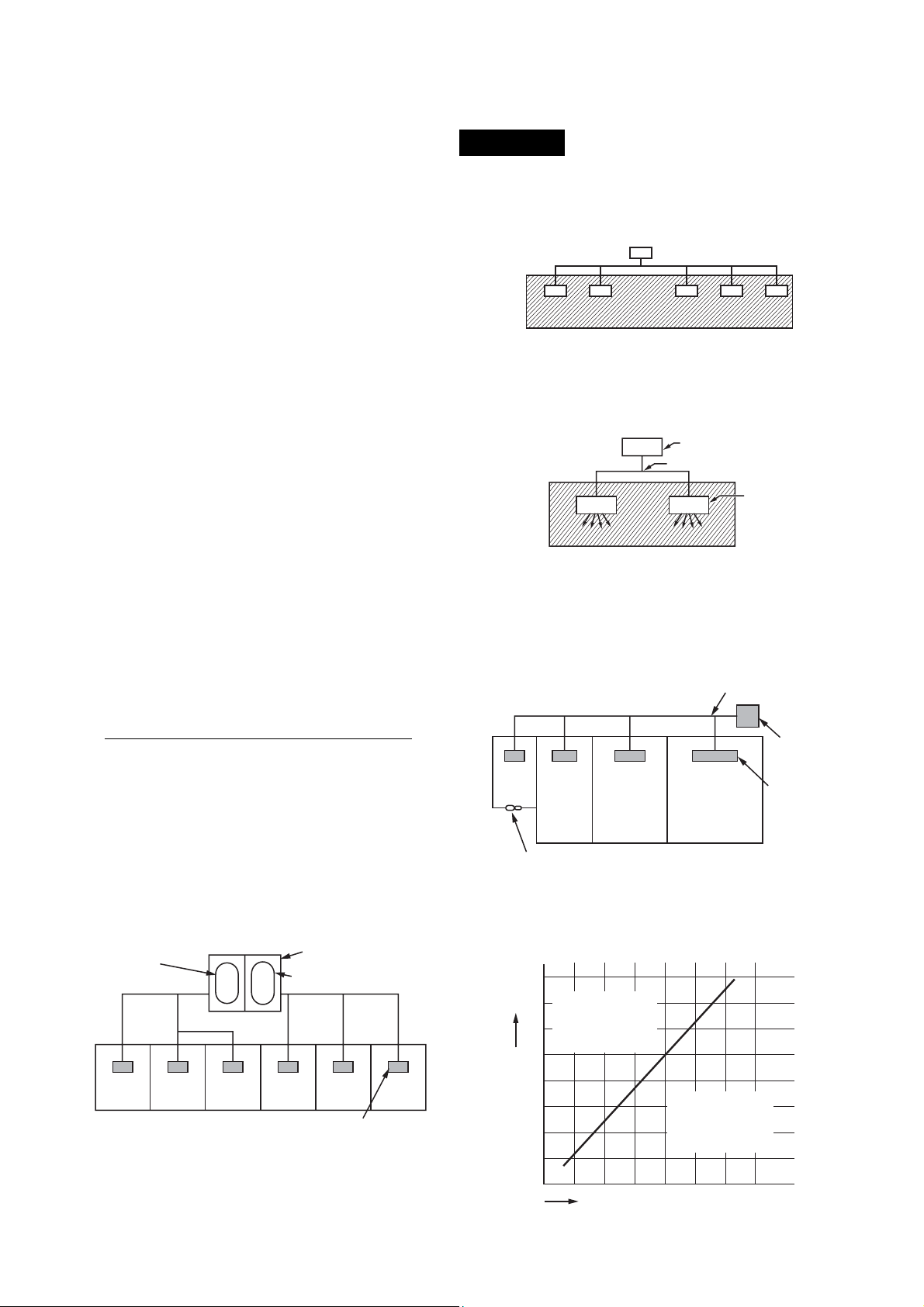
1. Applications for indoor remote controller
1-1
1-2
Basic function
Individual control
Air conditioner is
individually operated
at a distance.
GROUP control
One remote controller
can control group of
Max. 8 indoor units.
Operating on the
same setting
Main remote controller
Indoor
unit
Remote
controller
Indoor
unit
Remote
controller
System diagram
Wireless remote controller
Indoor
unit
Possible up to Max.
total length 500m
Receiver unit
Wireless
remote
controller
Max.8 indoor units
Indoor
unit
Indoor
unit
Indoor
Possible up to Max.total length 500m
unit
Model
• Wired remote controller
RBC-AMT21E
• Simple remote controller
RBC-AS21E
• Wireless remote controller
kit
TCB-AX21U(W)-E
RBC-AX22CE
TCB-AX21E
• Wired remote controller
RBC-AMT21E
• Simple remote controller
RBC-AS21E
Two remote control
Air conditioner is
1-3
controlled by two
remote controllers at
two places.
Control by
weekly timer
1-4
Weekly schedule
operation
Wired system Wireless system
Indoor
Indoor
unit
Wireless
remote
controller 1
Master
Remote
controller
Master
Remote
controller
Side
Possible up to Max.
total length 500m
Indoor
Wired & Wireless
combination control
(Either controller
should be set as
side controller)
Remote
controller
Weekly timer function
• Setting of ON-OFF
3 times par day
Indoor
unit
• Timer time is displayed.
• Designation of holiday
unit
unit
Wireless
remote
controller 2
Side
Wireless
remote
controller
• Wired remote controller
RBC-AMT21E
• Simple remote controller
RBC-AS21E
• Wireless remote controller
kit
TCB-AX21U(W)-E
RBC-AX22CE
TCB-AX21E
• Wired remote controller
RBC-AMT21E
+
• Weekly timer
RBC-EXW21E
Remote
controller
Weekly
timer
36
Page 37

2. Application controls for central remote controller
Basic function ModelSystem diagram
Header
Central management
2-1
controller for 64 units
Zone
Zone
Zone
Zone
Powe r
supply
4
U3, U4
3
2
U3, U4
1
unit
U3, U4
U1, U2
Header
unit
U1, U2
Header
unit
U1, U2
FS unit
Central
Single phase
220/230/240V
remote controller
Super MMS
Outdoor unit
Line-3
U5, U6
Indoor remote controller
U5, U6
Indoor remote controller
Outdoor unit
Line-1
Indoor remote controller
Indoor unit
Outdoor unit
Line-2
Super HRM
Indoor unit
Super MMS
Indoor unit
• Central remote controller
TCB-SC642TLE
<Indoor remote controller>
• Wired remote controller
RBC-AMT21E
• Simple remote controller
RBC-AS21E
Central remote
controller
Weekly timer
2-2
+
Weekly operation
schedule
can be set by
connecting a weekly
timer to the central
remote controller
Function of central remote controller
• Individual control up to 64 indoor units.
• Individual control for max. 64 indoor units divided 1 to
4 zone. (Up to 16 indoor units for each zone.)
• Up to 16 outdoor header units are connectable.
• 4 type central control setting to inhibit individual
operation by remote controller can be selected.
• Setting for one of 1 to 4 zone is available.
• Usable with other central control devices
(Up to 10 central control devices in one control circuit)
• Two control mode selectivity
Central controller mode/Remote controller mode
• Setting of simultaneous ON/OFF 3 times for each day
of the week combined with weekly timer.
Outdoor unitU3, U4
Single phase
220/230/240V
Power
supply
remote controller
FS
unit
Indoor remote controller
Central
Indoor unit
Weekly timer
U1, U2
• Central remote controller
TCB-SC642TLE
+
• Weekly timer
RBC-EXW21E
<Indoor remote controller>
• Wired remote controller
RBC-AMT21E
or
• Simple remote controller
RBC-AS21E
37
Page 38

Basic function
System diagram Model
Remote central
control without
2-3
indoor remote
controller
U3, U4
Powe r
supply
Single phase
220/230/240V
Example of grouping operation
Powe r
supply
Single phase
220/230/240V
Powe r
supply
Single phase
220/230/240V
FS unit
Central remote controller
U3, U4
Central remote controller
U3, U4
Central remote controller
Outdoor unit
Even when grouping operation is performed
by connecting multiple indoor units to 1 line,
the indoor remote controller is required.
Outdoor unit
U1, U2
(Group)
U1, U2
Indoor unit
FS unit
Available
Outdoor unit
U1, U2
(Group)
FS unit
Available
• Central remote controller
TCB-SC642TLE
<Indoor remote controller>
• Wired remote controller
RBC-AMT21E
Central manage-
2-4
ment control with
“1 : 1 model”
Powe r
supply
U3, U4
Header
unit
U1, U2
FS
unit
Central remote controller
Super HRM
Indoor unit
Indoor remote controller
*
"1:1 model"
connection interface
1
* TOSHIBA Digital Inverter System and Super Digital
Inverter System
38
• Central remote controller
TCB-SC642TLE
• “1 : 1 model” connection
interface
TCB-PCNT30TLE
RAV-SM560KRT-E,
SM800KRT-E are not
available
<Indoor remote controller>
• Wired remote controller
RBC-AMT21E
• Simple remote controller
RBC-AS21E
Page 39

3. Application control for network
3-1-1
Basic function
LONWORKS
®
(*1)
System diagram
LON Center
LON Talk
LN Interface
FS
unit
TCB-
Super HRM
Remote controller
*
"1:1 model"
connection interface
1
*1 TOSHIBA Digital Inverter System and Super Digital
Inverter System
The LONWORKS interface shall be connected between a building management computer and the Super
HRM and Super MMS system.
Max. 64 indoor units are connectable per interface.
Model
• LN interface
TCB-IFLN640TLE
• “1 : 1 model” connection
interface
TCB-PCNT30TLE
RAV-SM560KRT-E,
SM800KRT-E are not
available
<Indoor remote controller>
• Wired remote controller
RBC-AMT21E
or
• Simple remote controller
RBC-AS21E
3-1-2 BACnet
(*2)
BAC net center
BAC net
server
TCN-NET
relay interface
FS
unit
TCB-
Super HRM
Remote controller
*
"1:1 model"
connection interface
1
*1 TOSHIBA Digital Inverter System and Super Digital
Inverter System
The local server shall be connected under the BACnet
network, and shall be connected the Super HRM and
Super MMS system through the interface.
• BACnet server
BMS-LSV
******
• TCS-Net Relay Interface
BMS-IFLSV1E
• “1 : 1 model” connection
interface
TCB-PCNT30TLE
RAV-SM560KRT-E,
SM800KRT-E are not
available
<Indoor remote controller>
• Wired remote controller
RBC-AMT21E
• Simple remote controller
RBC-AS21E
*1) LONWORKS : Registered trademark Echelon corporation.
*2) BACnet™ : Registered trademark Echelon corporation.
39
Page 40

Basic function
System diagram
Model
3-2-1
Touch screen
controller
Touch screen controller
(Max. 512 indoor units are controller)
Intelligent
server
TCS-NET
Relay Interface
FS unit
Super HRM
Remote controller
Energy monitoring relay interface
Digital I/O relay interface
"1:1 model"
connection interface
1
*
*1 TOSHIBA Digital Inverter System and Super Digital
Inverter System
*2 With energy monitoring and billing function
Combination of touch screen and local server.
• Touch screen controller
BMS-TP0640ACE
BMS-TP5120ACE
BMS-TP0640PWE*
BMS-TP5120PWE*
2
2
• Intelligent server
BMS-LSV2E
BMS-STCC01E (Soft
ware)
• TCS-Net Relay Interface
BMS-IFLSV1E
• Energy Monitoring Relay
Interface
BMS-IFWH3E
• Digital I/O Relay Interface
BMS-IFDD01E
• “1 : 1 model” connection
interface
TCB-PCNT30TLE
RAV-SM560KRT-E,
SM800KRT-E are not
available
<Indoor remote controller>
• Wired remote controller
RBC-AMT21E
• Simple remote controller
RBC-AS21E
40
Page 41

8. ACCESSORIES
Options for application controls
• Application controls of indoor unit
Appliance name Model name Contents of application control
Remote location
ON/OFF control box
Network adapter TCB-PCNT20E Central control with AI-Network system Indoor unit
"1:1 model" connection
interface
• Application controls of outdoor unit
Appliance name Model name Contents of application control
Power peak-cut control
board
External master
ON/OFF control board
Error output control
board
TCB-IFCB-4E
TCB-PCNT30TLE
TCB-PCDM2E
TCB-PCMO2E
TCB-PCIN2E
· Monitoring from outside
· ON/OFF command from external signals
Central control with " 1:1 model"
(link Toshiba Digital Inverter system and
Super Digital Inverter system)
Power peak-cut (Standard function)
Power peak-cut (Expansion function)
Snowfall fan control
External master ON/OFF control
Night operation (sound reduction) control
Operation mode selection control
Operation and error monitoring from
external position
Connecting device or
setting method
Indoor unit
Indoor unit
Connecting device or
setting method
Inverter assembly of the
header outdoor unit
Accessories parts for indoor unit
• Remote controller
Indoor unit type Accessory parts name Model Applicable model
4-way Air Discharge Cassette Type
2-way Air Discharge Cassette Type
1-way Air Discharge Cassette Type
Concealed Duct Type
Concealed Duct, High Static Pressure Type
Under Ceiling Type
High Wall Type (1 series)
High Wall Type (2 series)
Floor Standing Cabinet Type
Floor Standing Concealed Type
Floor Standing Type
Wired remote controller
Central remote controller
Weekly timer
Simple remote controller
Remote sensor
Wire-less remote controller kit
1
*
RBC-AMT21E
TCB-SC642TLE
RBC-EXW21E
RBC-AS21E
TCB-TC21LE
TCB-AX21U(W)-E
RBC-AX22CE Under Ceiling Type
TCB-AX21E
WH-H2UE
Common parts for
all type model
4-way Air
Discharge
Cassette Type
Universal Type
Except concealed
(
duct high static
pressure type)
High Wall Type
(2 series)
Packed with indoor
unit
*1: For handling the Wireless Remote Controller kit, consult your dealer about availability.
41
Page 42

• Panels and accessories
Indoor unit type Accessory parts name Model Application model Remarks
Required accessory Ceiling panel RBC-U21PG(W )-E
4-way Air Discharge
Cassette Type
2-way Air Discharge
Cassette Type
1-way Air Discharge
Cassette Type
Concealed Duct
Type
Concealed Duct
High Static Pressure
Type
Under Ceiling Type Optional
Optional
Required accessory Ceiling panel
Required accessory Ceiling panel
Optional
Optional
Super Long Life Filter TCB-LF1601UE
High Efficiency Filter 65 TCB-UFM1601UE
High Efficiency Filter 90 TCB-UFH1601UE
Fresh air and Filter
Chamber
Fresh air inlet Box TCB-GB1601UE Be used with TCB-GFC1601UE
Auxiliary fresh air Flange TCB-FF101URE
Spacer for height
adjustment
Air discharge direction kit TCB-BC1601UE Three-piece set
High Efficiency Filter 65
High Efficiency Filter 90
Ceiling panel
Suction Canvas
Filter Chamber
Filter kit for underside
High Efficiency Filter 65
High Efficiency Filter 90
Long Life Pre-Filter
Filter Chamber
Drain pump kit
Drain pump kit TCB-DP22CE AP0151-0481
Elbow piping kit
TCB-GFC1601UE
TCB-SP1601UE
RBC-UW136PG AP0071-0121
RBC-UW266PG AP0151-0301
RBC-UW466PG AP0361-0561
RBC-US165PG AP0151-0181
RBC-US265PG AP0241
RBC-UY135PG AP0071-0121
TCB-UFM11BFCE AP0071-0121/AP0241-0301 AP0241-AP0301 use two pcs.
TCB-UFM21BFCE AP0151-0181/AP0361-0561 AP0361-AP0581 use two pcs.
TCB-UFM11BE AP0071-0121
TCB-UFM21BE AP0151-0181
TCB-UFM31BE AP0241-0301
TCB-UFM41BE AP0361-0561
TCB-UFH51BFCE AP0071-0121/AP0241-0301 AP0241-AP0301 use two pcs.
TCB-UFH61BFCE AP0151-0181/AP0361-0561 AP0361-AP0561 use two pcs.
TCB-UFH51BE AP0071-0121
TCB-UFH61BE AP0151-0181
TCB-UFH71BE AP0241-0301
TCB-UFH81BE AP0361-0561
RBC-UD281PE(W) AP0071-0121
RBC-UD501PE(W) AP0151-0181
RBC-UD801PE(W) AP0241-0301
RBC-UD1401PE(W) AP0361-0561
TCB-CA281BE AP0071-0121
TCB-CA501BE AP0151-0181
TCB-CA801BE AP0241-0301
TCB-CA1401BE AP0361-0561
TCB-FC281BE AP0071-0121
TCB-FC501BE AP0151-0181
TCB-FC801BE AP0241-0301
TCB-FC1401BE AP0361-0561
TCB-FK281BE AP0071-0121
TCB-FK501BE AP0151-0181
TCB-FK801BE AP0241-0301
TCB-FK1401BE AP0361-0561
TCB-UFM1D-1E AP0181/0481 AP0481 use two pcs.
TCB-UFM2D-1E AP0241-0361 Use two pcs.
TCB-UFM3DE AP0721-0961
TCB-UFH5D-1E AP0181/0481 AP0481 use two pcs.
TCB-UFH6D-1E AP0241-0361 Use two pcs.
TCB-UFH7DE AP0721-0961
TCB-PF1D-1E AP0181/0481 AP0481 use two pcs.
TCB-PF2D-1E AP0241-0361 Use two pcs.
TCB-PF3DE AP0721-0961
TCB-FCY21DE AP0181
TCB-FCY31DE AP0241-0361
TCB-FCY51DE AP0481
TCB-FCY100DE AP0721-0961
TCB-DP31DE AP0181-0481
TCB-DP32DE AP0721-0961
TCB-KP12CE AP0151-0181
TCB-KP22CE AP0241-0481
Be used with TCB-GFC1601UE
For underside suction
For underside suction
(Half panel for underside
suction)
For underside suction
For rear suction
* Required accessories when
using Drain Pump Kit
42
Page 43

1. Accessory Parts for 4-Way Air Discharge Cassatte type (Detail)
External view Name Model name Note
Dust collecting effect : 50%
Super long life
filter
High efficiency
filter 65
TCB-LF1601UE
TCB-UFM1601UE
High Efficiency
Filter 90
TCB-UFH1601UE
(Weight method)
Operation time : 10,000hours
Reuse is available
Use with TCB-GFC1601UE
Dust collecting effect : 65%
(NBS Colorimetric method)
Operation time : 2500hours
Reuse is not available with
TCB-GFC1601UE
Dust collecting effect : 90%
(NBS Colorimetric method)
Operation time : 1800 hours
Reuse is not available with
TCB-GFC1601UE
Fresh Air and
Filter Chamber
Fresh Air Inlet
Box
Auxiliary Fresh
Air Flange
Spacer for
Height
Adjustment
Air Discharge
Direction kit
TCB-GFC1601UE
TCB-GB1601UE
TCB-FF101URE
TCB-SP1601UE
TCB-BC1601UE
For fresh air intake and
installing high efficiency filter
or super long life filter
Use with TCB-GFC1601UE
Easy fresh air intake by
using the knockout hole of
indoor unit.
(dia.=100mm)
Height = 50mm
Air direction change by
cutting off of air discharge
port (3 pcs.)
TCB-BC1601UE
TCB-FF101URE
TCB-GFC1601UE
TCB-SP1601UE
RBC-U21PG(W)-E
TCB-GB1601UE
TCB-UFM1601UE
TCB-UFH1601UE
TCB-LF1601UE
2. Accessory for 4-way Air Discharge Cassette Type:Combination Pattern
Ceiling Panel
RBC-U21PG (W)-E
Wireless remote controller kit
TCB-AX21U (W)-E
Auxiliary fresh air flange
TCB-FF101URE
Fresh air and filter chamber (as fiter chamber)
TCB-GFC1601UE
Panel
Optional
Parts
Ceiling Panel
Wireless remote controller kit
Auxiliary fresh air flange
Fresh air and filter chamber
(Used for filter frame)
Fresh air inlet box +
Fresh air and filter chamber
Super long life filter
High efficiency filter (65%)
High efficiency filter (90%)
Spacer for height adjustment
Air discharge direction kit
(*1)Setup of air volume by connecting main wired remote controller and item code setting is necessary.
(*2) Procedure same as (*1) is necessary when indoor unit is used under the different air volume from setting at shipment.
RBC-U21PG (W)-E
TCB-AX21U (W)-E
TCB-FF101URE
TCB-GFC1601UE
TCB-GB1601UE +
TCB-GFC1601UE
TCB-LF1601UE
TCB-UFM1601UE
TCB-UFH1601UE
TCB-SP1601UE
TCB-BC1601UE
OK
OK
OK
OK
OK
OK
OK
OK
OK
OK
OK
OK
OK
OK
OK
OK
OK
OK
OK
OK
OK
OK
OK
OK
OK
OK
OK
OK
(*1)
OK
(*1)
-
(*1)
-
OK
(*2)
OK
OK
OK
OK
OK
OK
OK
OK
OK
OK
43
Fresh air inlet box + Fresh air and filter chamber
TCB-GB1601UE + TCB-GFC1601UE
Super long life fitler
TCB-LF1601UE
High efficiency filter (65%)
TCB-UFM1601UE
High efficiency filter (90%)
TCB-UFH1601UE
Spacer for height adjustment
TCB-SP1601UE
Air discharge direction kit
TCB-BC1601UE
OK
OK
OK
(*1)
(*1)
OK
OK
OK
OK
OK
OK
OK
OK
-
-
-
OK
OK
-
(*1)
OK
OK
OK
OK
-
-
-
-
OK
-
-
OK
OK
OK
OK
OK
OK
OK
OK
OK
(*2)
OK
OK
OK
-
OK
-
-
-
OK
Page 44

9. TECHNICAL SPECIFICATIONS
50Hz
Indoor unit (50Hz specifications)
• 4-way Air Discharge Cassette Type
Model na me MMU- AP0091H AP0121H AP0151H AP0181H AP0241H AP0271H AP0301H AP0361H AP0481H AP0561H
Cooling/Heating capacity (Note 1) (kW) 2.8/3.2 3.6/4.0 4.5/5.0 5.6/6.3 7.1/8.0 8.0/9.0 9.0/10.0 11.2/12.5 14.0/16.0 16.0/18.0
Power supply 1 phase 50Hz 230V (220 – 240V) (Power exclusive for indoor is required.)
Electrical
characteristics
Appearance
Outer
dimension
Total weight
Heat exchanger Finned tube
Running current (A) 0.17 0.19 0.21 0.24 0.35 0.59 0.81 0.83
Power consumption (kW) 0.020 0.022 0.026 0.032 0.048 0.070 0.110 0.112
Starting current (A) 0.30 0.33 0.36 0.42 0.59 0.87 1.23 1.26
Main unit Heat-insulating material attached Zinc hot dipping steel plate
Ceiling
Panel
Main unit
Ceiling
panel
Main unit (kg) 20 22 23 28
Ceiling panel (kg) 4.5
Model RBC-U21PG (W)-E
Panel color Moon white (Munsell/2.5GY 9.0/0.5)
Height (mm) 256 319
Width (mm) 840
Depth (mm) 840
Height (mm) 35
Width (mm) 950
Depth (mm) 950
Soundproof/Heat-insulating
material
Fan Turbo fan
Fan unit
Air filter Standard filter attached (Long life filter)
Controller Remote controller
Connecting
pipe
Sound level(Note 2)
High (Mid./Low)
Note 1 : The cooling capacities and electrical characteristics are measured under the conditions specified by JIS B 8615 based on the
Standard air flow High
(Mid./Low)
Motor (W) 60 90
Gas side (mm) Ø9.5 Ø12.7 Ø15.9
Liquid side (mm) Ø6.4 Ø9.5
Drain port (Nominal dia.) 25 (Polyvinyl chloride tube)
Non-flammable insulation
(m³/h)
(dB(A)) 30/29/27 31/29/27 32/29/28 34/31/28 37/33/30 40/36/33 44/38/34 45/40/34
800
(730/680)
930
(830/790)
1,050
(920/800)
1,200
(920/820)
1,320
(1,110/850)
1,680
(1300/1,070)
2,040
(1,430/1,130)
2,090
(1,520/1,230)
reference piping. The reference piping consists of 5 m of main piping and 2.5 m of branch piping connected with 0 meter height.
Note 2 : The sound level are measured in an anechoic chamber in accordance with JIS B8616. Normally, the values measured in
the actual operating environment become larger than the indicated values due to the effects of external sound.
Note : Rated conditions Cooling : Indoor air temperature 27°C DB/19°C WB, Outdoor air temperature 35°C DB
Heating : Indoor air temperature 20°C DB, Outdoor air temperature 7°C DB/6°C WB
44
Page 45

• 2-way Air Discharge Cassette Type
50Hz
Model name MMU- AP0071WH AP0091WH AP0121WH AP0151WH AP0181WH AP0241WH AP0271WH AP0301WH
Cooling/Heating capacity (kW) 2.2/2.5 2.8/3.2 3.6/4.0 4.5/5.0 5.6/6.3 7.1/8.0 8.0/9.0 9.0/10.0 14.0/16.0
(kW) 0.070 0.072 0.105 0.106 0.250
1 phase 50Hz 230V (220 – 240V) (Power exclusive for indoor is required.)
RBC-UW136PG RBC-UW266PG
Electrical
characteristics
Appearance
Outer
dimension
Power supply
Running current (A) 0.31 0.32 0.46 0.47 1.16
Power
consumption
Power factor (%) 97 99 98 98
Starting current (A) 0.47 0.60 0.89 0.98 1.33
Main unit Heat-insulating material attached Zinc hot dipping steel plate
Ceiling
panel
Main
unit
Ceiling
panel
Model
Panel color Light ivory (Munsell 10Y 9/0.5)
Height (mm) 398 406
Width (mm) 830 1,350 1,650
Depth (mm) 550 620
Height (mm) 8
Width (mm) 1,000 1,520 1,898
Depth (mm) 650 680
AP0481WH
China only
1 phase
50Hz 220V
RBC-UW46
6PG
Total weight
Heat exchanger Finned tube
Soundproof/Heat-insulating material Non-flammable insulation
Fan unit
Air filter Standard filter attached (Long life filter)
Controller Remote controller
Connecting
pipe
Sound level (Note 2)
(High/Mid./Low)
Note 1 : The cooling capacities and electrical characteristics are measured under the conditions specified by JIS B 8615 based on the
Main unit (kg) 33 44 48 52
Ceiling panel (kg) 8 11 18
Fan Centrifugal fan
Standard air flow
(High/Mid./Low)
Motor (W) 53 39 53 92
Gas side (mm) Ø9.5 Ø12.7 Ø15.9
Liquid side (mm) Ø6.4 Ø9.5
Drain port (Nominal dia.) 25 (Polyvinyl chloride tube)
(m³/h) 570/510/450 780/700/600 1140/960/720
(dB(A)) 34/32/30 35/33/30 38/35/33 40/37/34 45/42/39
1260/
1140/
960
1920/
1500/
1050
reference piping. The reference piping consists of 5 m of main piping and 2.5 m of branch piping connected with 0 meter height.
Note 2 : The sound level are measured in an anechoic chamber in accordance with JIS B8616. Normally, the values measured in
the actual operating environment become larger than the indicated values due to the effects of external sound.
Note : Rated conditions Cooling : Indoor air temperature 27°C DB/19°C WB, Outdoor air temperature 35°C DB
Heating : Indoor air temperature 20°C DB, Outdoor air temperature 7°C DB/6°C WB
45
Page 46

50Hz
• 1-way Air Discharge Cassette Type
Model name MMU- AP0071YH AP0091YH AP0121YH AP0151SH AP0181SH AP0241SH
Cooling/Heating capacity (Note 1) (kW) 2.2/2.5 2.8/3.2 3.6/4.0 4.5/5.0 5.6/6.3 7.1/8.0
Power supply 1 phase 50Hz 230V (220 – 240V) (Power exclusive for indoor is required.)
Electrical
characteristics
(Note 2)
Appearance
Outer
dimension
Total w e i g h t
Heat exchanger Finned tube
Running current (A) 0.24 0.48 0.55
Power consumption (kW) 0.053 0.103 0.115
Power factor (%) 95 93 91
Starting current (A) 0.6 0.8 1.1
Main unit Heat-insulating material attached Zinc hot dipping steel plate
Ceiling
panel
Main unit
Ceiling
panel
Main unit (kg) 22 27 31
Ceiling panel (kg) 3.5 8 9
Model RBC-UY135PG RBC-US165PG RBC-US265PG
Panel color W : Silky shade (1Y8.5/0.5)
Height (mm) 235 198
Width (mm) 850 1,000 1,200
Depth (mm) 400 655
Height (mm) 18 10
Width (mm) 1,050 1,220 1,420
Depth (mm) 470 755
Soundproof/Heat-insulating material Non-flammable insulation
Fan Centrifugal fan
Fan
Standard air flow
unit
(High/Mid./Low)
Motor (W) 22 34
Controller Remote controller
Room thermostat Attached
Air filter Standard filter attached (Long life filter)
Gas side (mm) Ø9.5 Ø12.7 Ø15.9
Connecting
pipe
Sound level (Note 2)
(High/Mid./Low)
Note 1 : The cooling capacities and electrical characteristics are measured under the conditions specified by JIS B 8615 based on the
Liquid side (mm) Ø6.4 Ø9.5
Drain port (Nominal dia.) 25 (Polyvinyl chloride tube)
(m³/h) 540/480/420 780/720/660 1,200/1,140/1,020
(dB(A)) 42/39/34 42/39/35 43/41/37
reference piping. The reference piping consists of 5 m of main piping and 2.5 m of branch piping connected with 0 meter height.
Note 2 : The sound level are measured in an anechoic chamber in accordance with JIS B8616. Normally, the values measured in
the actual operating environment become larger than the indicated values due to the effects of external sound.
Note : Rated conditions Cooling : Indoor air temperature 27°C DB/19°C WB, Outdoor air temperature 35°C DB
Heating : Indoor air temperature 20°C DB, Outdoor air temperature 7°C DB/6°C WB
46
Page 47

• Concealed Duct Type
50Hz
Model name MMD-
Cooling/Heating capacity (Note 1) (kW) 2.2/2.5 2.8/3.2 3.6/4.0 4.5/5.0 5.6/6.3 7.1/8.0 8.0/9.0 9.0/10.0 11.2/12.5 14.0/16.0 16.0/18.0
Power supply 1 phase 50Hz 230V (220 – 240V) (Power exclusive for indoor is required.)
Electrical
characteristics
Appearance Main unit Zinc hot dipping steel plate
Outer
dimension
Total weight
Running current (A) 0.29 0.34 0.43 0.52 0.61 0.83 0.98
Power consumption (kW) 0.033 0.039 0.050 0.060 0.071 0.107 0.128
Starting current (A) 0.5 0.59 0.75 0.90 1.05 1.44 1.70
Height (mm) 320
Main unit
Suction
ceiling
panel
Main unit (kg) 28 32 43 55
Ceiling panel (kg) 3.5 4 6 7
Width (mm) 550 700 1,000 1,350
Depth (mm) 80 0
Height (mm) 9
Width (mm) 630 780 1,080 1,430
Depth (mm) 50 0
AP0071BH AP0091BH AP0121BH AP0151BH AP0181BH AP0241BH AP0271BH AP0301BH AP0361BH AP0481BH AP0561BH
Heat exchanger Finned tube
Sound proof/Heat-insulating material Non-f lammable in sulat ion
Fan Centrifugal fan
Standard air flow High
(Mid./Low)
Fan unit
Motor (W) 120
External static pressure
(factory setting)
External static pressure (Pa) 100
Air filter Standard filter attached (Long life filter)
Controller Remote controller
Gas side (mm) Ø9.5 Ø12.7 Ø15.9
Connecting
pipe
Sound level (Note 2)
(High/Mid./Low)
Note 1 : The cooling capacities and electrical characteristics are measured under the conditions specified by JIS B 8615 based on the
Liquid side (mm) Ø6.4 Ø9. 5
Drain port (Nominal dia.) 25 (Polyviny l chloride tu be)
(m³/h)
(Pa) 40
(dB(A)) 30/28/26 31/29/27 32/30/28 33/31/29 34/32/29 36/34/32 38/36/32
480
(420/340)
570
(490/400)
650
(540/480)
780
(660/540)
1,140
(990/870)
1,260
(1080/870)
1,620
(1410/120 0)
1,980
(1710/1490)
reference piping. The reference piping consists of 5 m of main piping and 2.5 m of branch piping connected with 0 meter height.
Note 2 : The sound level are measured in an anechoic chamber in accordance with JIS B8616. Normally, the values measured in
the actual operating environment become larger than the indicated values due to the effects of external sound.
Note : Rated conditions Cooling : Indoor air temperature 27°C DB/19°C WB, Outdoor air temperature 35°C DB
Heating : Indoor air temperature 20°C DB, Outdoor air temperature 7°C DB/6°C WB
47
Page 48

50Hz
• Concealed Duct High Static Pressure Type
Model name MMD- AP0181H AP0241H AP0271H AP0361H AP0481H AP0721H AP0961H
Cooling/Heating capacity (Note 1) (kW) 5.6/6.3 7.1/8.0 8.0/9.0 11.2/12.5 14.0/16.0 22.4/25.0 28.0/31.5
Power supply 1 phase 50Hz 230V (220 – 240V) (Power exclusive for indoor is required.)
Running current (A) 0.81 1.35 1.63 1.84 5.25 5.52
Electrical
characteristics
Appearance Zinc hot dipping steel plate
Outer
dimension
Total weight (kg) 50 52 56 67 150
Heat exchanger Finned tube
Soundproof/Heat-insulating material Non-flammable insulation
Fan
unit
Air filter Option or field supply
Power
consumption
Power factor (%) 99 96 98 98 99 99
Starting current (A) 1.3 3.5 4.1 4.8 13.6 14.8
Height x Width x Depth (mm) 380 x 850 x 660
Fan Centrifugal fan
Standard air flow (m³/h) 900 1,320 1,600 2,100 3,600 4,200
Motor (W) 160 260 370 x 3
External static pressure
(Factory setting)
External static pressure (Pa) 68.6-137-196
Air flow limit
Lower limit/Upper limit
(kW) 0.184 0.299 0.368 0.414 1.200 1.260
380 x 1,200 x 660
(Pa) 137
(m³/h) 720/1,080 1,060/1,580 1,280/1,920 1,680/2,520 2,880/4,320 3,360/5,040
470 x 1,380 x 1,250
Controller Remote controller
Gas side (mm) Ø12.7 Ø15.9 Ø22.2
Connecting
pipe
Sound level (Note 2)
(High/Mid./Low)
Note 1 : The cooling capacities and electrical characteristics are measured under the conditions speciied by JIS B 8615 based on the
Liquid side (mm) Ø6.4 Ø9.5 Ø12.7
Drain port (Nominal dia.) 25 (One side of male screw)
(dB(A)) 37 40 49 50
reference piping. The reference piping consists of 5 m of main piping and 2.5 m of branch piping connected with 0 meter height.
Note 2 : The sound level are measured in an anechoic chamber in accordance with JIS B8616. Normally, the values measured in
the actual operating environment become larger than the indicated values due to the effects of external sound.
Note : Rated conditions Cooling : Indoor air temperature 27°C DB/19°C WB, Outdoor air temperature 35°C DB
Heating : Indoor air temperature 20°C DB, Outdoor air temperature 7°C DB/6°C WB
48
Page 49

50Hz
• Under Ceiling Type
Model name MMC- AP0151H AP0181H AP0241H AP0271H AP0361H AP0481H
Cooling/Heating capacity (Note 1) (kW) 4.5/5.0 5.6/6.3 7.1/8.0 8.0/9.0 11.2/12.5 14.0/16.0
Power supply 1 phase 50Hz 230V (220 – 240V) (Power exclusive for indoor is required.)
Electrical
characteristics
Appearance White (Munsell 10Y 9.3/0.4)
Outer
dimension
Total weight (kg) 22 26 34
Heat exchanger Finned tube
Soundproof/Heat-insulating material Non-flammable insulation
Fan unit
Controller Remote controller
Room thermostat Attached
Air filter Standard filter attached (Long life filter)
Running current (A) 0.29 0.32 0.42 0.78 0.84
Power consumption (kW) 0.033 0.038 0.050 0.091 0.110
Starting current (A) 0.43 0.48 0.62 1.17 1.25
Height x Width x Depth (mm) 210 x 910 x 680 210 x 1,180 x 680 210 x 1,595 x 680
Fan Centrifugal fan
Standard air flow
(High/Mid./Low)
Motor (W) 30 40 80
(m³/h) 720/600/540 780/660/540 1,110/900/840 1,650/1,380/1,200 1,800/1,560/1,320
Gas side (mm) Ø12.7 Ø15.9
Connecting
pipe
Sound level (Note 2)
(High/Mid./Low)
Note 1 : The cooling capacities and electrical characteristics are measured under the conditions specified by JIS B 8615 based on the
Liquid side (mm) Ø6.4 Ø9.5
Drain port (Nominal dia.) 20 (Polyvinyl chloride tube)
(dB(A)) 35/32/30 36/33/30 38/36/33 41/38/35 43/40/37
reference piping. The reference piping consists of 5 m of main piping and 2.5 m of branch piping connected with 0 meter height.
Note 2 : The sound level are measured in an anechoic chamber in accordance with JIS B8616. Normally, the values measured in
the actual operating environment become larger than the indicated values due to the effects of external sound.
Note : Rated conditions Cooling : Indoor air temperature 27°C DB/19°C WB, Outdoor air temperature 35°C DB
Heating : Indoor air temperature 20°C DB, Outdoor air temperature 7°C DB/6°C WB
49
Page 50

50Hz
• High Wall Type (1 series)
Model name MMK- AP0071H AP0091H AP0121H AP0151H AP0181H AP0241H
Cooling/Heating capacity (Note 1) (kW) 2.2/2.5 2.8/3.2 3.6/4.0 4.5/5.0 5.6/6.3 7.1/8.0
Power supply 1 phase 50Hz 230V (220 – 240V) (Power exclusive for indoor is required.)
Electrical
characteristics
Appearance
Outer
dimension
Total weight (kg) 18 19 25
Heat exchanger Finned tube
Soundproof/Heat-insulating material Non-flammable insulation
Fan Cross-flow fan
Fan
Standard air flow
unit
(High/Mid./Low)
Motor outlet (W) 30
Air filter Standard filter attached (Simple filter)
Running current (A) 0.30 0.32 0.35
Power consumption (kW) 0.035 0.037 0.040
Starting current (A) 0.36 0.42 0.47
Suction grille and side panel Silky mist (Munsell 1Y 8.9/0.5)
Discharge grille City gray (Munsell N6.5)
Bottom surface Silky mist (Munsell 1Y 8.9/0.5)
Height x Width x
Depth
(mm) 368 x 895 x 210 368 x 1,055 x 210 368 x 1,430 x 210
(m³/h) 600/540/480 780/660/600 1,200/1,020/900
Controller Remote controller
Gas side (mm) Ø9.5 Ø12.7 Ø15.9
Connecting pipe
Sound level (Note 2)
(High/Mid./Low)
Note 1 : The cooling capacities and electrical characteristics are measured under the conditions specified by JIS B 8615 based on the
Liquid side (mm) Ø6.4 Ø9.5
Drain port (Nominal dia.) 20 (Polyvinyl chloride tube)
(dB(A)) 39/34/31 42/38/35 42/38/35
reference piping. The reference piping consists of 5 m of main piping and 2.5 m of branch piping connected with 0 meter height.
Note 2 : The sound level are measured in an anechoic chamber in accordance with JIS B8616. Normally, the values measured in
the actual operating environment become larger than the indicated values due to the effects of external sound.
Note : Rated conditions Cooling : Indoor air temperature 27°C DB/19°C WB, Outdoor air temperature 35°C DB
Heating : Indoor air temperature 20°C DB, Outdoor air temperature 7°C DB/6°C WB
50
Page 51

50Hz
• High Wall Type (2 series)*
Model name MMK- AP0072H AP0092H AP0122H
Cooling/Heating capacity (Note 1) (kW) 2.2/2.5 2.8/3.2 3.6/4.0
Power supply 1 phase 50Hz 230V (220 – 240V) (Power exclusive for indoor is required.)
Electrical
characteristics
Appearance
Outer
dimension
Total w e ig h t (k g ) 11
Heat exchanger Finned tube
Soundproof/Heat-insulating material Non-flammable insulation
Running current (A) 0.17 0.18 0.19
Power consumption (kW) 0.017 0.018 0.019
Starting current (A) 0.22 0.23 0.24
Suction grille and side panel Moon white
Discharge grille Moon white
Bottom surface Moon white
Height x Width x
Depth
(mm) 275 x 790 x 208
*European market only
Fan Cross-flow fan
Fan
Standard air flow
unit
(High/Mid./Low)
Motor outlet (W) 30
Air filter Standard filter attached (Simple filter)
Controller Wireless remote controller (WH-H2UE, Packed with indoor unit)
Gas side (mm) Ø 9.5
Connecting pipe
Sound level (Note 2)
(High/Mid./Low)
Note 1 : The cooling capacities and electrical characteristics are measured under the conditions specified by JIS B 8615 based on the
Liquid side (mm) Ø 6.4
Drain port (Outer dia.) 16 (Polyvinyl chloride tube)
(m³/h) 480/420/360 510/450/360 540/450/360
(dB(A)) 35/32/29 36/33/29 37/33/29
reference piping. The reference piping consists of 5 m of main piping and 2.5 m of branch piping connected with 0 meter height.
Note 2 : The sound level are measured in an anechoic chamber in accordance with JIS B8616. Normally, the values measured in
the actual operating environment become larger than the indicated values due to the effects of external sound.
Note 3 : Wireless remote controller is packed with indoor unit.
Wired remote controller (RBC-AMT21E, RBC-AS21E) can be also connected.
Note : Rated conditions Cooling : Indoor air temperature 27°C DB/19°C WB, Outdoor air temperature 35°C DB
Heating : 20°C DB, Outdoor air temperature 7°C DB/6°C WB
51
Page 52

50Hz
• Floor Standing Cabinet Type
Model name MML- AP0071H AP0091H AP0121H AP0151H AP0181H AP0241H
Cooling/Heating capacity (Note 1) (kW) 2.2/2.5 2.8/3.2 3.6/4.0 4.5/5.0 5.6/6.3 7.1/8.0
Power supply 1 phase 50Hz 230V (220 – 240V) (Power exclusive for indoor is required.)
Running current (A) 0.26 0.43 0.47
Electrical
characteristics
Appearance Silky shade (1Y8.5/0.5)
Power consumption (kW) 0.056 0.092 0.102
Power factor (%) 94 93 94
Starting current (A) 0.60 0.80 1.10
Outer
dimension
Total weight (kg) 37 40 40
Heat exchanger Finned tube
Soundproof/Heat-insulating material Non-flammable insulation
Fan unit
Air filter Standard filter attached (Simple filter)
Controller Remote controller
Connecting
pipe
Sound level (Note 2)
(High/Mid./Low)
Height x Width x Depth (mm) 630 x 950 x 230
Fan Centrifugal fan
Standard air flow
(High/Mid./Low)
Motor outlet (W) 45
Gas side (mm) Ø9.5 Ø12.7 Ø15.9
Liquid side (mm) Ø6.4 Ø9.5
Drain port (Nominal dia.) 20 (Polyvinyl chloride tube)
(m³/h) 480/420/360 900/780/650 1,080/930/780
(dB(A)) 39/37/35 45/41/38 49/44/39
70
Note 1 : The cooling capacities and electrical characteristics are measured under the conditions specified by JIS B 8615 based on the
reference piping. The reference piping consists of 5 m of main piping and 2.5 m of branch piping connected with 0 meter height.
Note 2 : The sound level are measured in an anechoic chamber in accordance with JIS B8616. Normally, the values measured in
the actual operating environment become larger than the indicated values due to the effects of external sound.
Note : Rated conditions Cooling : Indoor air temperature 27°C DB/19°C WB, Outdoor air temperature 35°C DB
Heating : Indoor air temperature 20°C DB, Outdoor air temperature 7°C DB/6°C WB
52
Page 53

50Hz
• Floor Standing Concealed Type
Model name MML- AP0071BH AP0091BH AP0121BH AP0151BH AP0181BH AP0241BH
Cooling/Heating capacity (Note 1) (kW) 2.2/2.5 2.8/3.2 3.6/4.0 4.5/5.0 5.6/6.3 7.1/8.0
Power supply 1 phase 50Hz 230V (220 – 240V) (Power exclusive for indoor is required.)
Running current (A) 0.25 0.45 0.46
Electrical
characteristics
Appearance Zinc hot dipping steel plate
Power consumption (kW) 0.056 0.090 0.095
Power factor (%) 97 87 90
Starting current (A) 0.60 0.80 1.00
Outer
dimension
Total weight (kg) 21 29
Heat exchanger Finned tube
Soundproof/Heat-insulating material Non-flammable insulation
Fan unit
Air filter Standard filter attached (Simple filter)
Controller Remote controller
Connecting
pipe
Sound level (Note 2)
(High/Mid./Low)
Height x Width x
Depth
Fan Centrifugal fan
Standard air flow
(High/Mid./Low)
Motor (W) 19 70
Static pressure range (kPa) 0
Gas side (mm) Ø9.5 Ø12.7 Ø15.9
Liquid side (mm) Ø6.4 Ø9.5
Drain port (Nominal dia.) 20 (Polyvinyl chloride tube)
(mm) 600 x 745 x 220 600 x 1,045 x 220
(m³/h) 460/400/300 740/600/490 950/790/640
(dB(A)) 36/34/32 42/37/33
Note 1 : The cooling capacities and electrical characteristics are measured under the conditions specified by JIS B 8615 based on the
reference piping. The reference piping consists of 5 m of main piping and 2.5 m of branch piping connected with 0 meter height.
Note 2 : The sound level are measured in an anechoic chamber in accordance with JIS B8616. Normally, the values measured in
the actual operating environment become larger than the indicated values due to the effects of external sound.
Note : Rated conditions Cooling : Indoor air temperature 27°C DB/19°C WB, Outdoor air temperature 35°C DB
Heating : Indoor air temperature 20°C DB, Outdoor air temperature 7°C DB/6°C WB
53
Page 54

50Hz
• Floor Standing Type
Model name MMF- AP0151H AP0181H AP0241H AP0271H AP0361H AP0481H AP0561H
Cooling/Heating capacity (Note 1) (kW) 4.5/5.0 5.6/6.3 7.1/8.0 8.0/9.0 11.2/12.5 14.0/16.0 16.0/18.0
Power supply 1 phase 50Hz 230V (220 – 240V) (Power exclusive for indoor is required.)
Running current (A) 0.67 0.88 1.29 1.60
Electrical
characteristics
Appearance W : Silky shade (1Y 8.5/0.5)
Power consumption (kW) 0.150 0.190 0.280 0.350
Power factor (%) 97 94 95
Starting current (A) 0.90 1.10 1.70 2.10
Outer
dimension
Total weight (kg) 48 49 65
Heat exchanger Finned tube
Soundproof/Heat-insulating material Non-flammable insulation
Fan unit Fan Centrifugal fan
Motor (W) 37 63 110 160
Air filter Standard filter attached (Simple filter)
Controller Remote controller
Connecting
pipe
Sound level (Note 2)
(High/Mid./Low)
Height x Width x
Depth
Standard air flow
(High/Mid./Low)
Gas side (mm) Ø12.7 Ø15.9
Liquid side (mm) Ø6.4 Ø9.5
Drain port (Nominal dia.) 20 (Polyvinyl chloride tube)
(mm) 1750 × 600 × 210 1750 × 600 × 390
1,920/
(m³/h) 900/780/660 1,200/1,020/840
(dB(A)) 46/43/38 49/45/40 51/48/44 54/50/46
1,680/
1,380
2,160/1,860/1,560
Note 1 : The cooling capacities and electrical characteristics are measured under the conditions specified by JIS B 8615 based on the
reference piping. The reference piping consists of 5 m of main piping and 2.5 m of branch piping connected with 0 meter
height.
Note 2 : The sound level are measured in an anechoic chamber in accordance with JIS B8616. Normally, the values measured in
the actual operating environment become larger than the indicated values due to the effects of external sound.
Note : Rated conditions Cooling : Indoor air temperature 27°C DB/19°C WB, Outdoor air temperature 35°C DB
Heating : Indoor air temperature 20°C DB, Outdoor air temperature 7°C DB/6°C WB
54
Page 55

50Hz
Outdoor unit (50Hz)
Equivalent HP Equivalent to 8HP Equivalent to 10HP Equivalent to 12HP
Model name MMY- MAP0802FT8 MAP1002FT8 MAP1202FT8
Outdoor unit type Inverter unit
Cooling capacity (* 1) (kW) 22.4 28.0 33.5
Standard heating capacity (* 1) (kW) 25.0 31.5 35.5
Power supply (* 2) 3 phase 50Hz 400V (380 – 415V)
Running current (A) 9.25 13.15 19.85
Power consumption (kW) 6.07 8.54 12.90
Cooling
Electrical
characteristics
1)
(
*
Heating
External dimension (mm) Height 1,800 x Width 990 x Depth 750
Total weight (kg) 263
Color Silky shade (Munsell 1Y8.5/0.5)
Compressor
Fan unit
Heat exchanger Finned tube
Refrigerant R410A (Charged refrigerant amount) (* 3) (kg) 11.5
High-pressure switch (MPa) OFF : 2.90 ON : 3.73
Protective devices (* 5)
Refrigerant piping
specifications (
Control wiring Shield wire 1.25mm² x 2 cores. up to 2000m
Central remote controller
Max. No. of connected indoor units 13 16 16
Sound level (dB(A)) 57 58 59
1 : Rated conditions Cooling : Indoor air temperature 27°C DB/19°C WB, Outdoor air temperature 35°C DB
*
Type Hermetic type
Motor output (kW) 2.3 × 2 3.1 × 2 4.2 × 2
Fan Propeller fan
Motor output (kW) 0.60
Air volume (m³/h) 9,900 10,500
Connecting port dia
Connecting method
4)
*
Max. equivalent length (m) 150
Max. real length (m)
Max. total pipe length (Real length) (m) 300
Max. height difference (m)
The standard piping means that main pipe length is 5 m, branching pipe length 2.5 m of branch piping connected with a 0 meter height.
2 : The source voltage must not fluctuate more than ±10%.
*
3 : The amount does not consider extra piping lengths. Refrigerant must be added on site in accordance with the actual piping length.
*
4 : The maximum total piping length indicates the sum of one-way piping lengths on the liquid side or gas side.
*
5 : Discharge temp. sensor, Suction temp. sensor, Compressor case thermostat, High-pressure switch, Over-current sensor,
*
High-pressure sensor, Low pressure sensor, Over-current relay.
Power factor (%) 95 94 94
EER (Energy Efficiency Ratio) (kW/kW) 3.69 3.28 2.60
Starting current (A) 1.0 1.0 1.0
Running current (A)
Power consumption (kW) 6.29 8.73 9.65
Power factor (%) 95 94 94
EER (Energy Efficiency Ratio) (kW/kW) 3.97 3.61 3.68
Starting current (A) 1.0 1.0 1.0
Discharge gas side (mm) Ø19.1
Suction gas side (mm) Ø22.2 Ø28.6
Liquid side (mm) Ø12.7
Balance pipe (mm) Ø9.5
Discharge gas side Brazing
Suction gas side Brazing
Liquid side Flare
Balance pipe Flare
9.55 13.40 14.85
125 (However, if equivalent bend length is longer, equivalent length is
the standard.)
Outdoor unit is higher than indoor unit : 50
Outdoor unit is lower than indoor unit : 30
When connecting to outdoor unit :
(Shield wire) 1.25mm² x 2 cores. up to 1000m and
(Shield wire) 2.0mm² x 2 cores. up to 2000m
Heating : Indoor air temperature 20°C DB, Outdoor air temperature 7°C DB/6°C WB
55
Page 56

50Hz
Outdoor unit (Combination) (50Hz)
Equivalent HP Equivalent to 16HP Equivalent to 18HP Equivalent to 20HP
Set Model name Heat Recovery MMY- AP1602FT8 AP1802FT8 AP2002FT8
Outdoor unit type Inverter
Outdoor unit model Heat Recovery MMY- MAP0802FT8 MAP0802FT8 MAP1002FT8 MAP0802FT8 MAP1002FT8 MAP1002FT8
Rated cooling capacity (* 1) (kW) 45.0 50.4 56.0
Standard heating capacity (* 1) (kW) 50.0 56.5 63.0
Power supply (* 2) 3 phase 50Hz 400V (380 – 415V)
Running current (A) 19.68 23.29 26.90
Power
consumption
Cooling
Power factor (%) 95 96 96
EER (kW/kW)
(Energy Efficiency Ratio)
Electrical
characteristics (
External dimension (mm) Height 1,800 x Width 990 x Depth 750
To tal we ig ht (kg) 263
Color Silky shade (Munsell 1Y8.5/0.5)
Compressor
Fan unit
Heat exchanger Finned tube
Refrigerant R410A Charged amount (* 3) (kg) 11 .5
High-pressure switch (MPa) OFF : 2.90 ON : 3.73
Protective devices (* 5)
Refrigerant pipe
spec. (
*
Control wiring Shield wire 1.25mm² x 2 cores. up to 2000m
Central remote controller
Max. No. of connected indoor units 27 30 33
Sound level (dB(A)) 60 60.5 61
1 : Rated conditions Cooling : Indoor air temperature 27°C DB/19°C WB, Outdoor air temperature 35°C DB
*
4)
1)
*
Starting current (A) 1.0 1.0 1.0
Running current (A) 19.90 23.47 27.03
Power
consumption
Heating
Power factor (%) 95 96 96
EER (kW/kW)
(Energy Efficiency Ratio)
Starting current (A) 1.0 1.0 1.0
Typ e Hermetic type
Motor output (kW) 2.3 × 2 3.1 × 2 2.3 × 2 3.1 × 2
Fan Propeller fan
Motor output (kW) 0.6
Air volume (m³/h) 9,900 10,500 9,900 10,500
Discharge
gas side
Connecting
port dia.
Connecting
method
Max. equivalent length (m) 150
Max. real length (m) 125 (However, if equivalen t bend length is longer, equivalent length is the standard.)
Max. total pipe length
(Real length)
Max. height difference (m)
Suction gas
side
Liquid side (mm) Ø12.7
Balance side (mm) Ø9.5
Discharge gas side Brazing
Suction gas side Brazin g
Liquid side Flare
Balance side Flare
Heating : Indoor air temperature 20°C DB, Outdoor air temperature 7°C DB/6°C WB
The standard piping means that main pipe length is 5m, branching pipe length 2.5m of branch piping connected with a 0 meter height.
2 : The source voltage must not fluctuate more than ±10%.
*
3 : The amount does not consider extra piping lengths. Refrigerant must be added on site in accordance with the actual piping length.
*
4 : The maximum total piping length indicates the sum of one-way piping lengths on the liquid side or gas side.
*
System safety protection
5 : Discharge temp. sensor, Suction temp. sensor, Compressor case thermostat, High-pressure switch, Over-current sensor,
*
High-pressure sensor, Low pressure sensor, Over-current relay.
(kW) 13.01 15.42 17.89
3.46 3.27 3.13
(kW) 13.10 15.54 17.98
3.82 3.64 3.50
(mm) Ø19.1
(mm) Ø22.2
(m) 300
Outdoor unit is higher than indoor unit : 50
Outdoor unit is lower than indoor unit : 30
(Shield wire) 1.25mm² x 2 cores up to 1000m and (Shield wire) 2.0mm² x 2 cores up to 2000m
When connecting to outdoor unit :
56
Page 57

50Hz
Equivalent HP Equivalent to 24HP
Set Model name Heat Recovery MMY- AP2402FT8
Outdoor unit type Inverter
Outdoor unit model Heat Recovery MMY- MAP0802FT8 MAP0802FT8 MAP0802FT8
Rated cooling capacity (* 1) (kW) 68.0
Standard heating capacity (* 1) (kW) 76.5
Power supply (* 2) 3 phase 50Hz 400V (380 – 415V)
Running current (A) 29.52
Power
consumption
Cooling
Power factor (%) 96
EER
Electrical
characteristics
1)
(
*
External dimension (mm) Height 1,800 x Width 990 x Depth 750
To tal we ig ht
Color Silky shade (Munsell 1Y8.5/0.5)
Compressor
Fan unit
Heat exchanger Finned tube
Refrigerant R410A Charged amount (* 3) (kg) 11. 5
High-pressure switch (MPa) OFF : 2.90 ON : 3.73
Protective devices (* 5)
Refrigerant
pipe spec.
4)
(
*
Control wiring Shield wire 1.25mm² x 2 cores. up to 2000m
Central remote controller
Max. No. of connected indoor units 40
Sound level (dB(A)) 62
1 : Rated conditions Cooling : Indoor air temperature 27°C DB/19°C WB, Outdoor air temperature 35°C DB
*
(Energy Efficiency Ratio)
Starting current (A) 1.0
Running current (A) 29.86
Power
consumption
Heating
Power factor (% ) 97
EER (kW/kW)
(Energy Efficiency Ratio)
Starting current (A) 1.0
(kg) 263
Typ e Hermetic type
Motor output (kW) 2.3 × 2
Fan Propeller fan
Motor output (kW) 0.6
Air volume (m³/h) 9,900
Discharge gas
side
Connecting
port dia.
Connecting
method
Max. equivalent length (m) 150
Max. real length (m) 125 (However, if equivalent bend length is longer, equivalent length is the standard.)
Max. total pipe length
(Real length)
Max. height difference (m)
Suction gas
side
Liquid side (mm) Ø12.7
Balance side (mm) Ø9.5
Discharge gas side Brazing
Suction gas side Brazing
Liquid side Flare
Balance side Flare
Heating : Indoor air temperature 20°C DB, Outdoor air temperature 7°C DB/6°C WB
The standard piping means that main pipe length is 5m, branching pipe length 2.5m of branch piping connected with a 0 meter height.
2 : The source voltage must not fluctuate more than ±10%.
*
3 : The amount does not consider extra piping lengths. Refrigerant must be added on site in accordance with the actual piping length.
*
4 : The maximum total piping length indicates the sum of one-way piping lengths on the liquid side or gas side.
*
System safety protection
5 : Discharge temp. sensor, Suction temp. sensor, Compressor case thermostat, High-pressure switch, Over-current sensor,
*
High-pressure sensor, Low pressure sensor, Over-current relay.
(kW) 19.66
(kW/kW)
(kW) 20.04
(mm) Ø19.1
(mm) Ø22.2
(m) 300
Outdoor unit is higher than indoor unit : 50
Outdoor unit is lower than indoor unit : 30
(Shield wire) 1.25mm² x 2 cores up to 1000m, and (Shield wire) 2.0mm² x 2 cores up to 2000m
When connecting to outdoor unit :
3.46
3.82
57
Page 58

50Hz
Equivalent HP Equivalent to 26HP Equivalent to 28HP Equivalent to 30HP
Set Model name Heat Recovery MMY- AP2602FT8 AP2802FT8 AP3002FT8
Outdoor unit type Inverter
Outdoor unit model Heat Recovery MMY- M AP1002FT8 MAP0802FT8 MAP0802FT8 MAP 1002FT8 MAP1002FT8 MAP0802FT8 MAP1002FT8 MAP1002FT8 MAP1002FT8
Rated cooling capacity (* 1) (kW) 73 78.5 84.0
Standard heating capacity (* 1) (kW) 81.5 88.0 95.0
Power supply (* 2) 3 phase 50Hz 400V (380 – 415V)
Running current (A) 33.13 36.74 40.35
Power
consumption
Cooling
Power factor (%) 96 96 96
EER (kW/kW)
Electrical
characteristics
(
1)
*
External dimension (mm) Height 1,800 x Width 990 x Depth 750
To tal we ig ht (kg) 263
Color Silky shade (Munsell 1Y8.5/0.5)
Compressor
Fan unit
Heat exchanger Finned tube
Refrigerant R410A Charged amount (* 3) (kg) 11 .5
High-pressure switch (MPa) OFF : 2.90 ON : 3.73
Protective devices (* 5)
Refrigerant
pipe spec.
(
4)
*
Control wiring Shield wire 1.25mm² x 2 cores. up to 2000m
Central remote controller
Max. No. of connected indoor units 43 47 48
Sound level (dB(A)) 62 62.5 63
1 : Rated conditions Cooling : Indoor air temperature 27°C DB/19°C WB, Outdoor air temperature 35°C DB
*
(Energy Efficiency Ratio)
Starting current (A) 1.0 1.0 1.0
Running current (A) 33.42 36.99 40.55
Power
consumption
Heating
Power factor (%) 95 96 97
EER (kW/kW)
(Energy Efficiency Ratio)
Starting current (A) 1.0 1.0 1.0
Typ e Hermetic type
Motor output (kW) 3.1 × 2 2.3 × 2 3.1 × 2 2.3 × 2 3.1 × 2
Fan Propeller fan
Motor output (kW) 0.6
Air volume (m³/h) 10,500 9,900 10,500 9,900 10,500
Discharge
gas side
Connecting
port dia.
Connecting
method
Max. equivalent length (m) 150
Max. real length (m) 125 (However, if equivalent bend length is longer, equivalent length is the standard.)
Max. total pipe length
(Real length)
Max. height difference (m)
Suction gas
side
Liquid side (mm) Ø12.7
Balance side (mm) Ø9.5
Discharge gas side Brazing
Suction gas side Brazing
Liquid side Flare
Balance side Flare
Heating : Indoor air temperature 20°C DB, Outdoor air temperature 7°C DB/6°C WB
The standard piping means that main pipe length is 5m, branching pipe length 2.5m of branch piping connected with a 0 meter height.
2 : The source voltage must not fluctuate more than ±10%.
*
3 : The amount does not consider extra piping lengths. Refrigerant must be added on site in accordance with the actual piping length.
*
4 : The maximum total piping length indicates the sum of one-way piping lengths on the liquid side or gas side.
*
System safety protection
5 : Discharge temp. sensor, Suction temp. sensor, Compressor case thermostat, High-pressure switch, Over-current sensor,
*
High-pressure sensor, Low pressure sensor, Over-current relay.
(kW) 21.96 24.40 26.84
3.32 3.22 3.13
(kW) 22.09 24.53 27.11
3.69 3.59 3.50
(mm) Ø19.1
(mm) Ø22.2
(m) 300
Outdoor unit is higher than indoor unit : 50
Outdoor unit is lower than indoor unit : 30
(Shield wire) 1.25mm² x 2 cores up to 1000m, and (Shield wire) 2.0mm² x 2 cores up to 2000m
When connecting to outdoor unit :
58
Page 59

10. FAN CHARACTERISTICS
• In case of square duct flange of discharge section
MMD-AP0071BH, AP0091BH
140
120
100
80
60
Application limit
Standard H tap
Low static pressure H tap
External static pressure (Pa)
Air volume limit (Min)
40
20
0
200 400 600480
S
Long life filter
Air volume (m³/h)
Standard air volume: 480m³/h
High-static pressure 2H
High static pressure 1H tap
tan
d
ard L ta
p
tap
Air volume limit (Max)
MMD-AP0121BH
140
120
pplication lim
100
80
60
A
S
Low static pressure H tap
External static pressure (Pa)
40
20
0
300 500 570 700
Air volume limit (Min)
Standard L tap
Long life filter
Air volume (m³/h)
Standard air volume: 570m³/h
H
igh-static pressure 2H
it
H
igh static pressure 1H
tandard H
tap
tap
tap
Air volume limit (Max)
MMD-AP0151BH
140
120
100
80
60
External static pressure (Pa)
40
20
0
400 650600 800
Application limit
Air volume limit (Min)
Long life filter
High static pressure 1H tap
Standard H tap
Low static pressure H tap
Standard L tap
Air volume (m³/h)
Standard air volume: 650m³/h
High-static pressure 2H tap
Air volume limit (Max)
MMD-AP0181BH
140
120
100
80
60
Application limit
External static pressure (Pa)
Air volume limit (Min)
40
20
0
500 700 780 900
Long life filter
High static pressure 1H tap
Standard H tap
Low static pressure H tap
Standard L tap
Air volume (m³/h)
Standard air volume: 780m³/h
H
igh-static pressure 2H
tap
Air volume limit (Max)
59
Page 60

MMD-AP0241BH, AP0271BH
MMD-AP0301BH
140
120
100
80
60
External static pressure (Pa)
40
20
0
800 1000 1140 13001200
Application limit
Low static pressure H tap
Air volume limit (Min)
Standard L tap
Long life filter
Standard air volume: 1140m³/h
High-static pressure 2H tap
High static pressure 1H tap
Standard H tap
Air volume (m³/h)
Air volume limit (Max)
140
120
Application limit
100
80
60
External static pressure (Pa)
Air volume limit (Min)
40
20
0
900 1100 1260 1300
Low static pressure H tap
Standard L tap
Long life filter
Standard air volume: 1260m³/h
High-static pressure 2H tap
H
igh static pressure 1H tap
S
tandard H
tap
Air volume (m³/h)
limit (Max)
Air volume
MMD-AP0361BH
140
120
Application limit
100
80
60
limit (Min)
Air volume
External static pressure (Pa)
40
20
Low static pressure H tap
Standard air volume: 1620m³/h
High-static pressure 2H tap
High static pressure 1H tap
Standard H tap
Standard L tap
Air volume limit (Max)
MMD-AP0481BH, AP0561BH
140
120
100
80
60
External static pressure (Pa)
40
20
Application limit
High static pressure 1H tap
Low static pressure H tap
Air volume limit (Min)
Standard L tap
Standard air volume: 1980m³/h
High-static pressure 2H tap
Standard H tap
Air volume limit (Max)
0
1200 1620 2000
Long life filter
Air volume (m³/h)
60
0
1400 22001800 1980
Long life filter
Air volume (m³/h)
Page 61

• Concealed Duct High Static Pressure type
MMD-AP0181H
1.5
Medium static pressure tap
1.0
Low static pressure tap
Fan motor current (A)Outside static pressure (Pa)
0.5
250
200
150
100
50
Air volume lower limit
Standard air volume: 900 m³/h
High static pressure tap
50Hz
High static pressure tap
Medium static pressure tap
Low static pressure tap
60Hz
Air volume upper limit
MMD-AP0241H, AP0271H
2.0
Medium static pressure tap
1.5
Fan motor current (A)Outside static pressure (Pa)
1.0
300
250
200
150
Air volume lower limit
100
50
Standard air volume: 1,320 m³/h
High static pressure tap
Low static pressure tap
High static pressure tap
Medium static pressure tap
Low static pressure tap
50Hz
60Hz
Air volume upper limit
0
700 800 900 1,000 1,100
MMD-AP0361H
2.5
High static pressure tap
2.0
Medium static pressure tap
1.5
Fan motor current (A)Outside static pressure (Pa)
Low static pressure tap
1.0
250
200
150
100
Air volume lower limit
Air volume (m³/h)
Standard air volume: 1,600 m³/h
50Hz
High static pressure tap
Medium static pressure tap
Low static pressure tap
60Hz
Air volume upper limit
0
1,000 1,100 1,200 1,300
MMD-AP0481H
3.0
High static pressure tap
2.5
2.0
Medium static pressure tap
Fan motor current (A)Outside static pressure (Pa)
1.5
Low static pressure tap
0.5
250
200
150
100
Air volume lower limit
1,320
Air volume (m³/h)
High static pressure tap
Medium static pressure tap
Low static pressure tap
1,400 1,500 1,600
Standard air volume: 2,100 m³/h
50Hz
60Hz
Air volume upper limit
50
0
1,400 1,500 1,600 1,700 1,800
Air volume (m³/h)
61
50
0
1,500 2,000
2,100
2,500
Air volume (m³/h)
Page 62

11. DIMENSIONAL DRAWINGS
Indoor unit
• 4-way Air Discharge Cassette Type
MMU-AP0091H to P0561H
415
254.5
Z
35˚
723 hanging bolt pitch
panel external dimension
B97
35
381.6
950
Hanging bolt
M10 or W3/8 local arrange
840
480
227
Electric parts box
950
346.5
790 hanging bolt pitch
panel external dimension
Drain discharge port
A
Suction grille (Air suction port)
Air discharge port (4-way)
860 to 910
ceiling open dimension
For branch duct knockout square hole Ø150
(2 positions at right side)
840
250 70
270
105
105
210
860 to 910
ceiling open dimension
Refrigerant pipe
connecting port
(Gas)
Refrigerant pipe
connecting port
(Liquid)
88
130
Bottom face of ceiling Bottom face of ceiling
360
57.5
25
188
Bottom face
of ceiling
Knockout for simple OA
For Ø100
Z view
57
Indoor unit Bottom face of ceiling
64
(NOTE)
As ABS is used for the drain discharge
port of the main unit, the vinyl chloride
paste cannot be used.
Use the flexible hose (Band fix)
included in the package.
Drain-up standing-up size Space required for installation and servicing
Stand-up
Stand-up
640 or less
850 or less
• Wired remote controller (RBC-AMT21E)
4
2.7
120
Check port
( 450)
30
15 or more
1000 or more
200
Model A B
AP0091H to AP0301H
AP0361H to AP0561H
1000 or more
45
113
1000 or more
15 or more
174
250
319
mm
120
183
120
16
62
Check port
( 450)
200
Note: All dimensions are in mm.
Page 63

• 2-way Air Discharge Cassette Type
MMU-AP0071WH, AP0091WH, AP0121WH
Center of main unit
35
Center of panel
Electric parts box
95
Z view
Air discharge port
(2-way)
1000
Air suction port
(2-way)
30
Unit external dimension
Hanging bolt pitch
Ceiling open dimension
Panel external dimension
5mm
or more
Ceiling
1000 or more
Obstruction
830
880
960
1000
or more
1000
pitch 480
Hanging bolt
1000
or more
Ceiling open
Unit external
dimension 550
Panel external
dimension 620
dimension 650
398
8
Ceiling panel
(Procured by locally)
265
Ø200
222
156
Z
Branch duct knockout hole
(Provided also at the reverse side)
650
Hanging bolt
4-M10 procured locally
60
53
Bottom face of ceiling
Space required for installation and servicing
100mm
or less
Indoor unit
Bottom face of ceiling
160mm or less
508mm or less
Refrigerant pipe
connecting port
(Gas side Ø9.5)
Refrigerant pipe
connecting port
(Liquid side Ø6.4)
Power supply
connecting port
63
78
35
Drain pipe connecting port
Inner Ø32, Nominal Ø25
for vinyl chloride pipe
100
56
75 55
Pour water port
Ø150
210
Knockout hole for taking-in air
(Only at reverse side)
Note: All dimensions are in mm.
35
178
242
282
348
Page 64

MMU-AP0151WH, AP0181WH, AP0241WH, AP0271WH. AP0301WH
Z view
Center of main unit
35
Center of panel
Electric parts box
95
Air discharge port
(2-way)
Air suction port
(2-way)
Hanging bolt
30
Unit external dimension 1350
Hanging bolt pitch 1400
Ceiling open dimension 1480
Panel external dimension 1520
5mm
or more
1000 or more
Ceiling
Obstruction
1000
or more
1000
or more
Space required for installation and servicing
pitch 480
Unit external
dimension 550
Ceiling open
imension 620
Panel external
dimension 650
398
222
156
8
Ceiling panel
(Procured by locally)
Branch duct knockout hole
(Provided also at the reverse side)
Ø200
295
650
Hanging bolt
4-M10 procured locally
60
53
Z
Bottom face of ceiling
100mm
or less
160mm or less
Bottom face of ceiling
508mm or less
64
Refrigerant pipe
connecting port
(Gas side ØB)
Refrigerant pipe
connecting port
(Liquid side ØA)
35
Drain pipe connecting port
Inner Ø32, Nominal Ø25
for vinyl chloride pipe
56
100
Ø150
78
210
Power supply
connecting port
Model
MMU-AP0151WH to AP0181WH
MMU-AP0241WH to AP0301WH
Note: All dimensions are in mm.
75
55
Pour water port
35
178
Knockout hole for taking-in air
(Only at reverse side)
Ø6.4
Ø9.5
348
282
242
A
B
Ø12.7
Ø15.9
Page 65

MMU-AP0481WH
Center of main unit
95
Center of panel
Electric parts box
5
105
Z view
Air discharge port
(2-way)
1898
Air suction port
(2-way)
Unit external dimension 1650
Hanging bolt pitch 1700
Ceiling open dimension 1850
Panel external dimension 1898
5mm
or more
1000 or more
Ceiling
Obstruction
1000
or more
1000
or more
Space required for installation and servicing
100mm
or less
160mm or less
516mm or less
pitch 510
Unit external
Hanging bolt
dimension 620
406
230
8
Ceiling panel
(Procured by locally)
Ceiling open
Panel external
dimension 650
dimension 680
455
Ø200
166
Branch duct knockout hole
(Provided also at the reverse side)
Refrigerant pipe
connecting port
(Gas side Ø15.9)
Refrigerant pipe
connecting port
(Liquid side Ø9.5)
150
Z
Ø200
56
100
Hanging bolt
4-M10 procured locally
60
68
Bottom face of ceiling
Drain pipe connecting port
(VP25)
75
55
Pour water port
680
Bottom face of ceiling
• Wired remote controller (RBC-AMT21E)
4
2.7
120
120
16
65
15
86
Power supply
connecting port
Note: All dimensions are in mm.
Ø150
15
186
250
210
Knockout hole for taking-in air
(Only at reverse side)
290
356
Page 66

• 1-way Air Discharge Cassette Type
MMU-AP0071YH, AP0091YH, AP0121YH
Panel external dimension 1050
Ceiling open dimension 1010
Power supply
connecting port
Ceiling open
Panel external
dimension 470
dimension 430
Drain pipe connecting port
(VP25)
Refrigerant pipe connecting port
(Gas side) Ø9.5
Refrigerant pipe connecting port
(Liquid side) Ø6.4
Panel mounting hole
5 positions
Center of panel
Discharge louver
Hanging bolt
4-M10 procured locally
Ceiling panel
Procured by locally
Air discharge port
Air suction port
20 20
Support
metal
Bottom face of ceiling
• Wired remote controller
(RBC-AMT21E)
4
2.7
120
120
Dimensions
Model MMU-
AP0071YH, AP0091YH, AP0121YH
100 or more 100 or more 200 or more
16
Space required for installation and servicing
Note: All dimensions are in mm.
A
235
66
B
245
C
200
B
or more
Page 67

MMU-AP0151SH, AP0181SH, AP0241SH
Ø180
Ø150 knockout hole (For air taking-in)
96
G
30
65
Panel external dimension
Ceiling open dimension
Center of panel
B
A
30
125DC
20
30
Suction port
A
50 E F
10 10
80
60
80
100 100
Knockout hole for discharge forward
Pitch 200 × N
Dimensions
Model MMU-
AP0151SH,AP0181SH
AP0241SH
530
655
Ceiling open
dimension 695
110
H
100
20
160
19810
130
Refrigerant pipe connecting port
(Liquid side) ØI
Z
A
1220
1420
B
1160
1360
C
545
645
D
485
585
Z
Panel external
dimension 755
30
120
100
Refrigerant pipe connecting port
(Gas side) ØJ
530
630
440
335
255
E
F
470
570
Z view
Power supply
connecting port
Drain pipe connecting port
(VP25)
G
254
460
H
800
1000
Air discharge port
I
6.4
12.7
9.5
15.9
755
J
N
4
5
• Wired remote controller
(RBC-AMT21E)
4
2.7
120
120
16
200 or more
Ceiling
Space required for installation and servicing
1000 or more
Obstacle
67
1000 or more
1000 or more
Note: All dimensions are in mm.
Page 68

• Concealed Duct Standard Type
MMD-AP0071BH, AP0091BH, AP0121BH, AP0151BH, AP0181BH, AP0241BH,
AP0271BH, AP0301BH, AP0361BH, AP0481BH, AP0561BH
Drain pipe connecting port
(Inner Ø32 vinyl chloride pipe VP25 connection)
150
Ø125 knockout hole
(For air taking-in air)
91
10-Ø4 tapping screw
Ø160
Hanging bolt pitch A ± 7.5
(When attaching
directly)
70 to 270
B
C
Ceiling open
dimension D
E
Air suction
Hanging bolt 4-M10
(Procured locally)
142
Refrigerant pipe
connecting port
(Gas side ØF)
44
240
49
Refrigerant pipe
connecting port
(Liquid side ØG)
215
25 40
41 59
Air
discharge
Unit external dimension
50 638
131
Ø26 power supply,
remote controller
wires drawing-out
port
800
Hanging bolt pitch
700
498
41
50
50
Ceiling opening
393
196
243
Panel C, L
470
Air
suction
Model MMD-
AP0071BH, AP0091BH, AP0121BH
AP0151BH, AP0181BH
AP0241BH, AP0271BH, AP0301BH
AP0361BH, AP0481BH, AP0561BH
(Note)
Two of high efficiency filter and deodorant filter cannot applied.
(Note)
Be sure to place a check port A at the position indicated in the following figure for maintenance of the equipment.
Air outlet
Check port B
450mm
Air filter
700mm for maintenance of air filter 700mm for
ABC DE FG
616
766
1066
1416
550
700
1000
1350
Ceiling opening part
(150mm)
Check port A
450mm
300mm
maintenance of air filter
350
500
800
1150
D
600
750
1050
1400
600
750
1050
1400
550mm or less
Drain-up piping
470
620
920
1270
100mm or less
Note: All dimensions are in mm.
9.5
12.7
15.9
15.9
6.4
9.4
9.5
9.5
271mm or less
68
Page 69

• Concealed Duct High Static Pressure Type
MMD-AP0181H, AP0241H, AP0271H, AP0361H, AP0481H, AP0721H, AP0961H
MMD-AP0181H to AP0361H
Long hole for hanging bolt
(4-Ø12 × 72)
Power supply/
communication
piping port (Ø26)
(Under electric parts box)
Electric parts box
Refrigerant pipe connecting port
(Gas side ØB)
Drain pipe connecting port
(VP25)
Z view Z view
Screw hole for duct
mounting (4-M6)
AP0181H to AP0271H type
AP0181H
AP0241H, AP0271H, AP0361H, AP0481H
Air discharge port
Model MMD- A B
710
(Hanging bolt mounting pitch 800)
Refrigerant pipe connecting port
(Liquid side ØA)
Screw hole for duct
mounting (6-M6)
Air discharge port
Air suction port
Screw hole for duct
mounting (6-M6)
AP0361H type
6.4
12.7
9.5
15.9
Power supply/
communication
piping port (Ø26)
(Under electric parts box)
Electric parts box
Refrigerant pipe connecting port
(Gas side Ø15.9)
Space required for installation and servicing *1
MMD-AP0481H
Long hole for hanging bolt
(4-Ø12 × 72)
Refrigerant pipe connecting port
(Liquid side Ø9.5)
Screw hole for duct
Drain pipe connectingport
(VP25)
mounting (8-M6)
Z view
Screw hole for duct
mounting (8-M6)
Air suction port
Air discharge port
MMD-AP0721H, AP0961H
Long hole for
hanging bolt
(4-Ø12 × 92)
1288
(Hanging bolt mounting pitch)
1328
Refrigerant pipe connecting port
(Gas side Ø22.2)
1250
150
200
45
Drain pipe connecting port
(VP25)
1260
1380100
(Hanging bolt mounting pitch)
Electric parts box
Refrigerant pipe connecting port
(Liquid side Ø12.7)
31
624
698
190 250 250 250
470
Screw hole for duct
mounting (10-M6)
250 250 250 250 190
370
65
Screw hole for duct
mounting (10-M6)
250
Suction port
Discharge port
Service space
500 mm or more
Check port
600
Service space
or more
600 mm
1 Service spaces for MMD-AP0721H and AP0961H are different from
*
those in the above figure. For inquiries please contact us separately.
• Wired remote controller (RBC-AMT21E)
4
2.7
40635
120
120
16
69
Note: All dimensions are in mm.
Page 70

• Under Ceiling Type
MMC-AP0151H, AP0181H, AP0241H, AP0271H, AP0361H, AP0481H
Upper piping drawing-out port (Knockout hole)
Power supply cable taking-in port
(Knockout)
Remote controller piping
taking-in port (Knockout hole)
70
320 170
Drain port VP20
Left drain size
(Inner diam. Ø26, hose attached)
Piping drawing-out port
(Knockout port)
(Hanging position)
Refrigerant pipe (Liquid side ØD)
Refrigerant pipe (Gas side ØC)
Hanging bolt
Within 50
B (Hanging position)
A
Ceiling surface
Unit
Drain pipe
connecting port
Model MMC-
AP0151H, AP0181H
AP0241H to AP0271H
AP0361H, AP0481H
ABCD
910
1180
1595
Wireless sensor
mounting section
(Option)
250 or more
250 or more
(Front side is placed to a level.)
Space required for installation and servicing
855
1125
1540
12.7
15.9
15.9
500
or more
6.4
9.5
9.5
• Wired remote controller
(RBC-AMT21E)
4
2.7
120
120
Remote controller cable taking-in port
Power supply taking-in port
(Knockout hole)
Remote controller cable taking-in port
(Knockout hole)
Air taking-in port
(Duct sold separately) (Knockout hole Ø92)
Piping hole on the wall
16
(Ø100 hole)
Drain left piping drawing-out port
(Knockout hole)
Note: All dimensions are in mm.
70
Page 71

• High Wall Type (1 series)
MMK-AP0071H, AP0091H, AP0121H
690 (Installation board)
Long hole for
wooden screw
15-6 × 30
Position of installation board hole
Long hole for anchor bolt
10-10 × 20 long hole
Upper end of installation board
Discharge port
(Air direction upward/downward/leftward/rightward is adjustable.)
Air suction port
Gas pipe 440
Liquid pipe 540
Drain pipe 560
(When drawing pipe from left)
At shipment
(Including installation board)
Piping port from left/right sides
(Knockout hole)
210
Including installation board (Accessory)
Earth screw (M4)
(Inner of electric parts box)
Refrigerant pipe
connecting port
Gas side Ø9.5
9.5
Drain pipe
connecting port
• Wired remote controller (RBC-AMT21E)
Refrigerant pipe
connecting port
Liquid side Ø6.4
30 or more
300 or more 300 or more
Space required for service
71
4
2.7
120
120
16
Note: All dimensions are in mm.
Page 72

MMK-AP0151H, AP0181H
690 (Installation board)182.5 182.5
Long hole for
wooden screw
15-6 × 30
Position of installation board hole
Long hole for anchor bolt
10-10 × 20 long hole
Upper end of installation board
Air discharge port
(Air direction upward/downward/leftward/rightward is adjustable.)
Air suction port
Gas pipe 440
Liquid pipe 540
Drain pipe 560
(When drawing pipe from left)
At shipment
(Including installation board)
Piping port from left/right sides
(Knockout hole)
210
Including installation board (Accessory)
Earth screw (M4)
(Inner of electric parts box)
Refrigerant pipe
connecting port
Liquid side Ø6.4
Refrigerant pipe
connecting port
Gas side Ø12.7
Drain pipe
connecting port
30 or more
300 or more 300 or more
Space required for service
72
Note: All dimensions are in mm.
Page 73

MMK-AP0241H
1090 (Installation board)170 170
Long hole for
wooden screw
21-6 × 30
Position of installation board hole
Long hole for anchor bolt
16-10 × 20 long hole
Upper end of installation board
Air discharge port (Air direction upward/
downward/leftward/rightward is adjustable.)
(When drawing pipe from left)
Air suction port
Gas pipe 440
Liquid pipe 540
Drain pipe 560
At shipment
(Including installation board)
Piping port from left/right sides
(Knockout hole)
210
Including installation board (Accessory)
Earth screw (M4)
(Inner of electric parts box)
Refrigerant pipe
connecting port
Gas side Ø15.9
Refrigerant pipe
connecting port
Liquid side Ø9.5
Drain pipe
connecting port
30 or more
300 or more 300 or more
Space required for service
73
Note: All dimensions are in mm.
Page 74

• High Wall Type (2 series)*
MMK-AP0072H, AP0092H, AP0122H
*European market only
Air inlet part
275
60
Air outlet gril
60
790
790
790
790
60
275
54.5
208
208
Knockout
48
48
208
275
6
60
208
48
6
Knockout
48
54.5
Hock for insulation plate
Refrigerant pipe connecting port
Gas side Ø 9.5
Space required for service
321
275
Drain pipe
Refrigerant pipe connecting port
Liquid side Ø 6.4
100mm or more
170mm or more
*300mm or more170mm or more
*(For attached Flow Selector unit of
heat recovery model)
Note: All dimensions are in mm.
74
Page 75

• Floor Standing Cabinet Type
MML-AP0071H, AP0091H, AP0121H, AP0151H, AP0181H, AP0241H
Hole fixing floor
(2-Ø10)
Air discharge port
Air suction port
Dimensions
Lower refrigerant piping port
(50 × 100 knockout hole)
Refrigerant pipe port
(50 × 100 knockout hole)
(Both sides)
130
Operation switch section
(Sold separately)
100
( )
left side
Power supply cord hole
(Ø26 knockout) (Both sides)
Hole fixing wall
(Ø10-Ø20 knockout pulsometor hole × 2)
Hole fixing wall
(2-10 × 24 long hole)
Earth screw
(M6)
Refrigerant pipe port
(Ø130 knockout hole)
Model MML- B
AP0071H, AP0091H, AP0121H
AP0151H, AP0181H
AP0241H
Drain pipe connecting port
(Ø20)
Space required for service
Figure shows piping at the left side
(Front side)
1000 or more
Wall
500
or more
A
Ø9.5
Ø12.7
Ø15.9
(Front side)
Ø6.4
Ø6.4
Ø9.5
Refrigerant pipe
connecting port
(Liquid side ØB)
Refrigerant pipe
connecting port
(Gas side ØA)
300
or more
Piping positional
drawing
Wall
Note: All dimensions are in mm.
75
Page 76

• Floor Standing Concealed Type
MML-AP0071BH, AP0091BH, AP0121BH, AP0151BH, AP0181BH, AP0241BH
Hole fixing floor (Discharge port size in flange)
Ceiling board section
150
or more
(Service space)
No. Name
Pipe connecting port at liquid side (ØE)
Pipe connecting port at gas side (ØF)
Drain pipe connecting port (20A)
Electric parts box
(Earth terminal is provided in inner side.)
Air filter
(Air discharge port size in flange)
G-Ø4.7 hole
(Front side and rear side each)
4-Ø15 hole
(For mounting rear side)
150
or more
(Service space)
Expansion
valve box
Dimensions
Model MML- ABCD E F G
AP0071BH, AP0091BH, AP0121BH
AP0151BH, AP0181BH
AP0241BH
2-Ø4.7 hole
(Left/right side each)
610 580 550 4
910 880 850 7
2-12 × 18 long hole
(Hole fixing floor)
9.5 5
6.4
12.7
9.5 15.9
8
• Wired remote controller (RBC-AMT21E)
4
120
2.7
120
16
Note: All dimensions are in mm.
76
Page 77

• Floor Standing Type
MMF-AP0151H, AP0181H, AP0241H, AP0271H
Wall
Incase of installing distance
( )
50mm from wall
Lower refrigerant piping port
(50 × 120 Knockout hole)
Installation plate
Discharge
port
30 × 3
600
80
30 × 3
Control
part
Control
cover
Wall
Wall
a
Wall
b
Space required for service
(In case of right side piping )
Wall
Front
1000
More than
More
than
500
More than
200
Wall
Front
Dtain
Installation plate
Suction port
Refrigerant piping hole (Back side)
(Ø130 Knockout hole)
hose
Dimensions
Model A B
MMF-AP0151H, AP0181H
MMF-AP0241H, AP0271H
Details of hole for back side piping
Refrigerant piping port (Both side)
(Ø80 Knockout hole)
Earth screw (M4)
Refrigerant piping hole (Bottom side)
(50 × 120 Knockout hole)
Refrigerant piping joint
(Gas side A)
Ø12.7
Ø15.7
Ø6.4
Ø9.5
Floor
Refrigerant piping position
Refrigerant piping joint
(Liquid side B)
Details of hole for lower side piping
2- lower hole
For M8 Screw bolt
( )
or M8 Anchor bolt
a
b
In case 1770
In case 1773
Ø130 Knockout hole
(For backside piping)
4- lower hole
For M8 Screw bolt
( )
or M8 Anchor bolt
Note: All dimensions are in mm.
77
50 × 120 (Square hole )
(For under surface piping)
Page 78

MMF-AP0361H, AP0481H, AP0561H
Wall
Incase of installing distance
( )
50mm from wall
Lower refrigerant piping port
(50 × 120 Knockout hole)
Installation plate
Discharge
port
30 × 3
600
30 × 3
80
Control
part
Control
cover
Wall
Wall
a
Wall
b
Space required for service
(In case of right side piping )
Wall
More
than
Front
1000
More than
500
More than 200
Front
Wall
Installation plate
Suction port
Refrigerant piping hole
(Back side)
(Ø130 Knockout hole)
Dtain hose
Refrigerant piping joint
(Gas side Ø19)
Details of hole for back side piping
Floor
Refrigerant piping port (Both side)
(Ø80 Knockout hole)
Dtain hose
Earth screw (M4)
Refrigerant piping hole (Bottom side)
(50 × 120 Knockout hole)
Refrigerant piping position
Gas side
Liquid
side
Refrigerant piping joint
(Liquid side Ø9.5)
Details of hole for lower side piping
2- lower hole
For M8 Screw bolt
( )
or M8 Anchor bolt
a
b
In case 1770
In case 1773
Ø130 Knockout hole
(For backside piping)
4- lower hole
For M8 Screw bolt
( )
or M8 Anchor bolt
Note: All dimensions are in mm.
78
50 × 120 (Square hole )
(For under surface piping)
Page 79

Remote controller
• Wired remote controller
RBC-AMT21E
4
120
2.7
120
16
• Simple remote controller
RBC-AS21E
60
70
80
120
13
16
79
Page 80

• Wireless remote controller
TCB-AX21U (W)-E
186
186
• Wireless remote controller kit
32
58 19.5
177
61
RBC-AX22CE
58 19.5
130
65
177
61
80
Page 81

• Wireless remote controller kit
TCB-AX21E
58 19.5
61
• Weekly timer
177
83.5
4.4 x 9.4 long hole
70
4.4 x 5.4 long hole
13
83.5
RBC-EXW21E
4
120
2.7
120
16
81
Page 82

• Central remote controller
TCB-SC642TLE
128
160
80
116
47
15
13
160
6
6
148
(6)
36
148
121
128
80
13
47
21
(6)
121
69
Z
115
• Remote sensor
TCB-TC21LE
Z view (back side)
80
120
60
70
13
16
82
Page 83

• TCS-Net relay interface
BMS-IFLSV1E
200
6- 5.5 mounting holes
22787822
146.9
22787822
66
63.6
156
170
• Touch screen controller
BMS-TP0640ACE
BMS-TP5120ACE
BMS-TP0640PWE
BMS-TP5120PWE
54
495
242
99.3
82.5
48
16
75
302
55.5
30
19
75
70
95.7591.75
316
249
256
83
Page 84

• Intelligent server
BMS-LSV2E
Do not remove.
CAUTION
370
WARNING
Do not decompose.
• Energy mountoring relay interface/Digital I/O relay interface
BMS-IFWH3E
BMS-IFDD01E
198
39
Grommet for
power input
1818 53.5 103.5
234
220
246
1818
92.5
64.5
(193)
63.6
Grommet for
power meter
Grommet for
RS-485
84
Page 85

Outdoor unit
MMY-MAP0802FT8, MAP1002FT8, MAP1202FT8
755
790
750
anchor bolt pitch
(including steady leg)
4-15 × 20
(Long hole)
700
anchor bolt pitch
990
(NOTES)
1. If there is an obstacle at the upper side of the outdoor unit,
set the top end of the outdoor unit 2000mm apart from the obstacle.
2. Limit the height of the obstacle surrounding the outdoor unit to
800mm or less from the bottom end of the outdoor unit.
3. Draw out the pipe procured locally to the front of the outdoor unit
horizontally, and keep 500mm or more between the outdoor unit
and traversing pipe if placing pipe transversely.
2-60 × 150 square hole
(Hole for handling goods)
Knockout for
control piping (Ø27)
Earth-attaching section of bottom plate
610 100100
Knockout hole for
power piping (Ø48)
135
Refrigerant pipe
connecting port
(Suction gas side)
Refrigerant pipe
connecting port
(Discharge gas side)
Refrigerant pipe
connecting port
(Liquid side)
Foundation
80 80630
700
anchor bolt pitch
Refrigerant pipe
connecting port (Liquid side)
Refrigerant pipe
connecting port
(Discharge gas side)
A
755
anchor bolt pitch
Foundation
57
59
Model name
MMY-MAP0802FT8
MMY-MAP1002FT8
MMY-MAP1202FT8
1 Cutting position of L-shape pipe when pipe
at gas side is connected
(Recommended pipe connecting position)
1010 or more
500
or more
1750
or more
500
or more
10 or more
Front side
(For work and service)
10 or more
ØA
22.2
22.2
28.6
Space required for service
800
or less
500
or more
(Note 3)
600 or more
(1000 or more)
500
or more
Front side
Front side
500
or more
Front side
(Note 3)
Refrigerant pipe
connecting port
(Suction gas side)
Front side
600 or more
(1000 or more)
600
or more
Front side
500
or more
225
231
215
154
88
88115
144
Square hole
139
8
173
52
130
58
112
Details of front pipe/cabling holes Details of hole for piping at lower side (Plane view)
Note: All dimensions are in mm.
85
Page 86

<Two units connected>
MMY-AP1602FT8, AP1802FT8, AP2002FT8
(NOTES)
1. If there is an obstacle at the upper side of the outdoor unit,
set the top end of the outdoor unit 2000mm apart from the
obstacle.
2. Limit the height of the obstacle surrounding the outdoor unit
to 800mm or less from the bottom end of the outdoor unit.
3. Draw out the pipe procured locally to the front of the outdoor
unit horizontally, and keep 500mm or more between the
outdoor unit and traversing pipe if placing pipe transversely.
4. Arrange each outdoor unit in order of its capacity.
(Head unit > Follower)
1 2
165
1800
1640
700
20 or more
990 990
700
anchor bolt pitch
(310)
700
anchor bolt pitch
755
750
anchor bolt pitch
8-15 × 20
(Long hole)
790
(including steady leg)
Combination unit
MMY-AP1602FT8
MMY-AP1802FT8
MMY-AP2002FT8
500
or more
(Note 4)
Front side
(Note 3)
(1000 or more)
500
(Note 4)
Front side
600 or more
or more
Front side
Front side
500
or more
(Note 4)
(Note 3)
600 or more
(1000 or more)
600
or more
500
or more
88
Header
MAP0802FT8
MAP1002FT8
MAP1002FT8
Front side
Front side
Front side Front side
Front side
Front side
2000
Combination outdoor unit
MAP0802FT8
MAP0802FT8
MAP1002FT8
(Note 4)
500mm or more
10mm or more
Front side (For work and service)
500mm
or more
2020mm or more
Follower
20mm or more
1750mm or more
10mm
or more
800
or less
800
or less
Space required for service
Note: All dimensions are in mm.
86
Page 87

<Three units connected>
MMY-AP2402FT8, AP2602FT8, AP2802FT8, AP3002FT8
(NOTES)
1. If there is an obstacle at the upper side of the
outdoor unit, set the top end of the outdoor unit
2000mm apart from the obstacle.
2. Limit the height of the obstacle surrounding the
outdoor unit to 800mm or less from the bottom end
of the outdoor unit.
3. Draw out the pipe procured locally to the front of the
outdoor unit horizontally, and keep 500mm or more
between the outdoor unit and traversing pipe if
placing pipe transversely.
4. Arrange each outdoor unit in order of its capacity.
2
(Head unit > Follower
> Follower 3 )
1800
1640
anchor bolt pitch
1
20 or more
990 990
700
(310)
990
700
anchor bolt pitch
20 or more
(310)
32
700
anchor bolt pitch
755
790
750
anchor bolt pitch
12-15 × 20
(Long hole)
(including steady leg)
Combination unit
MMY-AP2402FT8
MMY-AP2602FT8
MMY-AP2802FT8
MMY-AP3002FT8
(Note 4)
500 or more
Front side
Front side
Front side
(Note 3)
600 or more
(1000 or more)
(Note 4)
500 or more
Front side
Front side
Front side
700
88 165
Header
MMY-MAP0802FT8
MMY-MAP1002FT8
MMY-MAP1002FT8
MMY-MAP1002FT8
(Note 4)
500 or more
Front side
Front side
Front side
(Note 3)
600 or more
(1000 or more)
600
or more
500
or more
Front side
Front side Front side Front side
3010
Combination outdoor unit
Follower
MMY-MAP0802FT8
MMY-MAP0802FT8
MMY-MAP1002FT8
MMY-MAP1002FT8
(Rear side)
Front side
Front side
(Note 4)
500mm or more
10mm or more 20mm or more 20mm or more
500mm
Front side (For work and service)
or more
Space required for service
(Front side)
MMY-MAP0802FT8
MMY-MAP0802FT8
MMY-MAP0802FT8
MMY-MAP1002FT8
3030mm or more
Follower
32
10mm
1750mm or more
or more
800
or less
800
or less
Note: All dimensions are in mm.
87
Page 88

FS unit (Flow Selector Unit)
RBM-Y1122FE, Y1802FE
Outdoor unit side
Refrigerant pipe connecting
port (Discharge gas)
Refrigerant pipe connecting
port (Liquid)
Refrigerant pipe connecting
port (Suction gas)
160
5739
154
21
44
87
(Specifications)
Model name
Indoor unit
side
Outdoor
unit side
Connecting indoor unit capacity
Power supply
Total weight
Dimension (mm)
Liquid side
Gas side
Liquid side
Discharge gas side
Suction gas side
(hanging bolt pitch)
320
250
(94)
(55)
190
(99) (55)
Y1802FE only
Earth
screw
RBM-Y1122FE
Connecting
pipe
Ø9.5
Ø15.9
Ø9.5
Ø12.7
Ø15.9
Connecting
method
1
*
Flare
1
*
Flare
Flare
Flare
007 to 030 type
Single phase 50Hz 230V(220-240V)
5kg
Height 190 X Width 250 X Depth 160
RBM-Y1802FE
Connecting
pipe
Connecting
method
Flare
Ø9.5
Flare
Ø15.9
Flare
Ø9.5Flare
Flare
Ø12.7
Flare
Ø15.9
036 to 056 type
5kg
Indoor unit side
Refrigerant pipe connecting
port (Liquid)
Refrigerant pipe connecting
port (Gas)
(99)
54
75
Accessory pipe and socket
Ø9.5, Brazing
3
Ø12.7, Brazing
2
Ø6.4, Brazing
1
For gas pipe
For gas pipe
31
79
007 to 012 type
015, 018 type
007 to 018 typeFor liquid pipe
(Installation space)
<RBM-Y1122FE (when attached pipes are used)>
(159)
or
50
more
2
3
(118)
or
200 or
more
<RBM-Y1122FE, RBM-Y1802FE>
200 or
more
1) When the capacity of connected indoor unit is less than 5.6 kW, adjust the pipe
*
50
more
or
50
more
or
50
more
1
300 or more
200 or
more
Outdoor unit
side
or more
500
size by using this accessory pipe.
88
50
Electrical parts
box cover
Note: All dimensions are in mm.
or
more
Indoor unit
side
Check port
450X450
Page 89

RBM-Y2802FE
Tentative
Outdoor unit side
Refrigerant pipe connecting
port (Discharge gas)
Refrigerant pipe connecting
port (Liquid)
Refrigerant pipe connecting
port (Suction gas)
199
684942
200
105
28 38
(Specifications)
Model name
Indoor unit
side
Outdoor unit
side
Total capacity of indoor unit (kW)
Power Supply
Total Weight
Dimension (mm)
Liquid side
Gas side
Liquid side
Discharge gas side
Suction gas side
470 (hanging bolt pitch)
(108) (398) (109)
(66)
(109)
(65)
Earth
screw
RBM-Y2802FE
8 kg
Connecting
method
Flare
Flare
Flare
Flare
Flare
Ø19.1 (Flare) Ø22.2 (Brazing)
2
Ø15.9 (Flare) Ø19.1 (Brazing)
1
Ø19.1 (Flare) Ø22.2 (Brazing)
2
Connecting
port
Ø12.7
1
*
Ø22.2
Ø12.7
1
*
Ø15.9
1
*
Ø22.2
18.0 to 28.0 or less
Single phase 50Hz 230V (220-240V)
Height 200 X Width 398 X Depth 199
Indoor unit side
Refrigerant pipe connecting
port (Gas)
Refrigerant pipe connecting
port (Liquid)
7732 12.5
67
105
Accessory pipe
31
(Installation space)
<RBM-Y2802FE (when attached pipes are used)>
(198)
1
2
(210)
400 or more
1) Adjust the pipe size by using this accessory pipe.
*
100
or
100
more
or
more
(210)
400 or more
or
50
Outdoor
unit
2
side
Electrical parts
box cover
or more
500
more
Indoor
unit
side
Check port
450X450
Note: All dimensions are in mm.
89
Page 90

Branch header/Branch joint
Branch header
RBM-HY1043E, HY1083E, HY2043E, HY2083E
Gas side
Liquid side
RBM-HY1043E
RBM-HY1083E
RBM-HY2043E
RBM-HY2083E
ØD
ØD
Gas side
Liquid side
Gas side
Liquid side
Gas side
Liquid side
Gas side
Liquid side
B 80 × n
B 80 × n
380
360
700
680
385.5
360
705.5
680
90
60
90
60
95.5
60
95.5
60
83.6
—
83.6
—
89.3
—
89.3
—
A
Insulator
A
Insulator
22.2
15.9
22.2
15.9
31.8
15.9
31.8
15.9
15.9
9.5
15.9
9.5
15.9
9.5
15.9
9.5
50
ØE
C
ØE
B
61
9
9
74.5
× 1
× 1
ØD
Accessory socket × Q’tyModel A B C ØD ØE n
6
× 4,
9
3
1
6
1
6
1
6
1
× 4,
× 8,
× 8,
× 2,
× 2
× 7,
× 7
3
7
7
3
3
7
7
× 4, 14 × 1, 18 × 1, 70 × 1
6
× 1,
9
× 8, 14 × 1, 18 × 1, 70 × 1
6
× 1,
9
× 2, 27 × 1, 59 × 1
9
× 7, 27 × 1, 59 × 1
90
Note: All dimensions are in mm.
Page 91

Y-shape branch joint
RBM-BY53E, BY103E
Gas side
Liquid side
ØD
ØC
ØC
ØB
ØD
Insulator
A
RBM-BY203E, BY303E
Gas side Liquid side
ØD
B
ØD
Insulator
A
ØC
RBM-BY53E
RBM-BY103E
RBM-BY203E
RBM-BY303E
Insulator
Gas side
Liquid side
Gas side
Liquid side
Gas side
Liquid side
Gas side
Liquid side
250
200
350
250
350
250
400
350
ØD
B
ØC
B
ØD ØD
A
5
80
70
80
80
80
80
110
80
15.9
12.7
22.2
15.9
31.8
15.9
38.1
22.2
12.7
9.5
19.1
12.7
28.6
15.9
38.1
19.1
× 2, 54 × 2,
1
× 2,
7
× 1, 10 × 1, 13 × 2, 18 × 1, 52 × 2, 70 × 1, 89 × 1
2
× 1,
16
× 1, 20 × 1, 27 × 1, 43 × 2, 48 × 1, 49 × 1, 58 × 1, 59 × 1
3
× 1,
61
× 3, 62 × 2, 71 × 2, 73 × 1, 74 × 1, 75 × 1, 76 × 1, 77 × 1
4
× 1,
ØD
9
× 1, 51 × 1
5
× 1
5
× 2,
6
× 1,
6
× 1,
9
× 2
7
× 1, 10 × 1, 13 × 2, 14 × 1, 18 × 1, 52 × 1
Accessory socket × Q’tyModel A B ØC ØD
9
× 1, 54 × 1
Insulator
A
91
Note: All dimensions are in mm.
Page 92

Accessory socket
1 2 5 54
Ø6.4
24
A
Ø9.5
Outer dia
3 6 9 51 4 7 10 13 52 89
ØB
ØBA
A
Ø15.9
51
3
6
9
35
32
28
38
6.4
9.5
12.7
19.1
A
Outer dia
ØB
Ø12.7
Outer dia
ØB
Ø19.1
Outer dia
54
10
13
52
89
ØBA
2
5
29
26
31
6.4
9.5
15.9
ØBA
4
7
39
39
36
33
43
53
6.4
9.5
12.7
15.9
22.2
28.6
14 18 70 85 86
ØB
A
Ø22.2
Outer dia
14
18
70
85
86
40
40
54
41
44
ØBA
15.9
19.1
28.6
12.7
9.5
16 20 43 48 49 58
ØB
A
Ø28.6
Outer dia
27 59 61 62 73 74 75 76 77
ØB
A
A
ØB
ØBA
Ø31.8
Outer dia
27
59
49
59
28.6
34.9
Ø38.1
Outer dia
Note: All dimensions are in mm.
16
20
43
48
49
58
61
62
71
73
74
75
76
77
50
52
50
54
52
62
55
66
66
66
66
64
62
62
ØBA
15.9
19.1
22.2
9.5
12.7
34.9
ØBA
34.9
41.3
28.6
22.2
19.1
15.9
12.7
9.5
92
Page 93

Y-shape branch joint
RBM-BY53FE
Suction gas side Accessory socket
Ø 12.7Ø 12.7
Ø 9.5
26
Ø 12.7
Outer dia Outer dia
2pcs.
Ø 15.9
12
Insulator
250
10
10
80
Discharge gas side Accessory socket
Ø 9.5
26
Ø 12.7
Outer dia Outer dia
2pcs.
09
Ø 12.7
28
Ø 15.9
Outer dia Outer dia
1pcs.
Ø 15.9
12
Insulator
250
10
10
Ø 12.7
80
Ø 12.7
5405
Ø 15.9
31
Ø 12.7
2pcs.
5405
Ø 15.9
31
Ø 12.7
1pcs.
Closed pipe
(41.9)
Ø 12.7
1pcs.
Liquid side Accessory socket
Ø 9.5Ø 9.5
Ø 6.4
24
Ø 9.5
Outer dia Outer dia
2pcs. 1pcs.
Note: All dimensions are in mm.
Ø 12.7
10
Insulator
200
9
9
70
93
0501
Ø 9.5
26
Ø 12.7
Page 94

Y-shape branch joint
RBM-BY103FE
Suction gas side Accessory socket
Ø 9.5
Ø 12.7
Ø 15.9
13 521007
Ø 22.2
22.2
Ø
18
Insulator
350
39
16
19.1
16
80
Ø
Ø 19.1
Outer dia Outer dia Outer dia Outer dia
1pcs.
89 70
Ø 28.6
19.1
Ø
53
Ø
19.1
Outer dia Outer dia
1pcs.
36
Ø 19.1
1pcs.
Ø 28.6
54
Ø 22.2
1pcs.
Discharge gas side Accessory socket
Ø
12.7
36
Ø 19.1
Outer dia
2 pcs. 1 pcs.
18
Ø
19.1
40
Ø 22.2
Outer dia
1 pcs.
Ø 22.2
18
Insulator
350
16
16
19.1
Ø
19.1
Ø
80
33
Ø 19.1
2pcs.
5210
Ø 22.2
Ø
Closed pipe
Ø 19.1
Outer dia
1 pcs.
42.5
Ø 19.1
2pcs.
42.5
19.1
Outer dia
(45)
Liquid side Accessory socket
Ø 15.9
12
Insulator
250
10
10
Ø 12.7
Ø 12.7
94
Ø 6.4
29
Ø 12.7
Outer dia
1 pcs.
80
Ø 15.9
31
Ø 12.7
Outer dia
1 pcs.
Ø 9.5
Ø 12.7
Note: All dimensions are in mm.
0502
26
Ø 12.7
Outer dia
2 pcs.
0954
28
Ø 15.9
Outer dia
1 pcs.
Page 95

Y-shape branch joint
RBM-BY203FE
Suction gas side Accessory socket
27
Ø 28.6
Ø 28.6
49
Ø 31.8
22
22
Insulator
350
80
22
Ø 28.6
Ø 31.8
Outer dia.
1 pc.
16 43
Ø 15.9
50
Outer dia. Outer dia. Outer dia.
1 pc. 2 pcs.
Discharge gas side Accessory socket
Ø 28.6
Ø 22.2
18
350
Insulator
16
80
Ø 19.1
16
Ø 19.1
1 pc.
89
Ø 28.6
54
Ø 22.2
Outer dia.
53
48 49
Ø 9.5
54
Ø 28.6
Outer dia. Outer dia.
1 pc. 1 pc.
Ø 12.7
58
Ø 22.2
50
Ø 28.6Ø 28.6
Ø 34.9
1 pc.
10
Ø 12.7
36
Ø 19.1
Outer dia. Outer dia.
1 pc.
Closed pipe
45
52
Ø 28.6
62
Ø 28.6
5270
Ø 22.2
42.5
Ø 19.1
2 pcs.
Ø 19.1
Outer dia. Outer dia.
1 pc.
Liquid side Accessory socket
51
Ø 15.9
Ø 19.1
Insulator
Ø 12.7
10
80
12
250
10
Ø 12.7
37.5
Ø 15.9
Outer dia. Outer dia.
1 pc. 1 pc.
05
Ø 9.5
26
Ø 12.7
Ø 6.4
Ø 15.9
2 pcs.1pc.
Note: All dimensions are in mm.
Ø 19.1
1 pc.
02
29
Ø 12.7
54
31
Ø 12.7
Outer dia.Outer dia.
95
Page 96

Y-shape branch joint
RBM-BY303FE
Suction gas side Accessory socket
77
Ø 9.5
62
Ø 38.1
Outer dia. Outer dia. Outer dia.
1 pc.
Ø 38.1
26
26
26
95
Ø 38.1
73
Ø 22.2
Insulator
400
Ø 38.1
66
Ø 38.1
Outer dia. Outer dia.
1 pc.
Discharge gas side Accessory socket
Ø 28.6
27
Ø 28.6
49
49
Ø 12.7
76 75
Ø 12.7
62
Ø 38.1
1 pc. 1 pc.
Ø 15.9
71 61
Ø 28.6
66
Ø 38.1
Outer dia.
2 pcs. 3 pcs.
Ø 34.9
20
Ø 19.1
52
64
Ø 38.1
55
Ø 38.1
52
Ø 31.8
Ø 31.8
22
22
Insulator
350
80
22
Ø 28.6
Outer dia.
1 pc. 1 pc. 1 pc.
43
Ø 22.2
50
Ø 28.6
Outer dia. Outer dia.
2 pcs.
Closed pipe
1 pc.
Liquid side Accessory socket
18 04
Ø 22.2
Insulator
16
Ø 19.1
18
16
Ø 19.1
40
Ø 22.2
Outer dia.
80
1 pc.
10 13
350
Ø 19.1
Ø 12.7
1 pc.
36
Ø 19.1
Outer dia.
Ø 6.4 Ø 9.5
1 pc.
Ø 15.9
1 pc.
Note: All dimensions are in mm.
Ø 28.6
Outer dia. Outer dia.
70
Ø 28.6
Ø 28.6
07
1 pc.
39
Ø 19.1Ø 19.1
Outer dia.
39
Outer dia.
33
Ø 19.1
Outer dia.
96
Page 97

Branch header
RBM-HY1043FE
Suction gas side Accessory socket
Ø 9.5
Ø 12.7
140906
Ø 15.9
Ø 22.2
18
90
68
380
80 80 50
80
83.6
Insulator
12
Ø
15.9
32
Ø 15.9
Outer dia
3pcs. 4pcs.
70
Ø 28.6
54
Ø 22.2
Outer dia
1pcs.
Discharge gas side Accessory socket
Ø 9.5
4 pcs.
18
Ø 19.1
1 pcs.
32
Ø 15.9
Outer dia
40
Ø 22.2
Outer dia
Ø 22.2
18
90
68
380
80 80 50
80
83.6
Insulator
12
Ø
15.9
Outer dia
Closed pipe
Outer dia
1pcs.
Ø 12.7
28
Ø 15.9
Outer dia
4 pcs.
Closed pipe
35
Ø 15.9
Outer dia
3 pcs.
28
Ø 15.9
35
(43.5)
Ø 15.9
(43.5)
1pcs.
850906
Ø 12.7
1 pcs.
40
Ø 22.2
Outer dia
41
Ø 22.2
Outer dia
Liquid side Accessory socket
Ø 6.4
330
45 80 80 80 45
12
Ø 15.9
12
Insulator
Ø 15.9
Ø 9.5
74.5
97
9
61
24
Ø 9.5
Outer dia
35
Ø 15.9
Outer dia Outer dia
1pcs.
Note: All dimensions are in mm.
06 0901
Ø 9.5
Closed pipe
(43.5)
1pcs.
32
Ø 15.9
Outer dia
(40.2)
35
Ø 9.5
Ø 12.7
28
Ø 15.9
Outer dia
1pcs.4pcs. 1pcs.
Page 98

Branch header
RBM-HY2043FE
Suction gas side Accessory socket
27
Ø 28.6
385.5
8095.5
66.223
80
80 50
89.3
12
Ø 15.9
1 pc.
49
Ø 31.8
Outer dia.
06
2 pcs.
32
Ø 15.9
Outer dia.
59
Ø 31.8
Insulator
Ø 34.9
1 pc.
59
Ø 31.8
Outer dia.
Closed pipe
Ø 15.9
Outer dia.
3 pcs.
35
Discharge gas side Accessory socket
7009
Ø 12.7
380
90
18
68
508080 80
83.6
12
Ø 15.9
28
Ø 15.9
4 pcs.
Closed pipe
Ø 34.9
1 pc.
(43.5)
54
Ø 22.2
Outer dia.Outer dia.
09
Ø 12.7Ø 9.5
2 pcs.
28
Ø 15.9
Outer dia.
Ø 22.2
Insulator
7 pcs.
35
(43.5)
Ø 15.9
Outer dia.
Liquid side Accessory socket
Ø 19.1
Ø 15.9
8045 80
330
12
Insulator
80
45
12
Ø 15.9
Ø 9.5
74.5
37.5
9
61
Ø 15.9
Outer dia.
1 pc.
Closed pipe
35
Ø 15.9
Outer dia. Outer dia.
1 pc. 3 pcs.
7 pcs.
(43.5)
Note: All dimensions are in mm.
0151
Ø 6.4
24
Ø 9.5
Outer dia.
35
(40.2)
Ø 9.5
98
Page 99

Branch header
RBM-HY1083FE
Suction gas side Accessory socket
Ø9.5
Ø12.7
140906
Ø15.9
32
Ø15.9
Outer dia Outer dia
70
Ø28.6
54
Ø22.2
Outer dia Outer dia
1pcs. 3pcs.
18
Ø22.2
90
68
700
808080
8080
50
8080
Ø15.9
12
83.6
Insulator
Discharge gas side Accessory socket
Ø9.5
32
Ø15.9
Outer dia Outer dia
18
Ø19.1
40
Ø22.2
Outer dia Outer dia
1pcs.
18
Ø22.2
90
68
700
808080
8080
8080
50
Ø15.9
12
83.6
Insulator
28
Ø15.9
Closed pipe
(43.5)
35
Ø15.9
Ø12.7
28
Ø15.9
Closed pipe
35
Ø15.9
7pcs.
(43.5)
1pcs.7pcs. 8pcs.
850906
Ø12.7
1pcs.8pcs. 8pcs.
40
Ø22.2
Outer dia
41
Ø22.2
Outer dia
Liquid side Accessory socket
06 0901
Insulator
650
45 80 80 80 80 80 80 80 45
12
Ø15.9
Ø9.5
9
74.5
61
B-view
12
Ø15.9
99
Ø6.4
24
Ø9.5
B
Outer dia Outer dia
35
Ø15.9
Outer dia Outer dia
1pcs. 3pcs.
Ø9.5
Closed pipe
43.5
Note: All dimensions are in mm.
32
Ø15.9
35
Ø9.5
40.2
Ø12.7
1pcs.8pcs. 1pcs.
28
Ø15.9
Outer dia
Page 100

Branch header
RBM-HY2083FE
Suction gas side Accessory socket
27
Ø 28.6
Ø 31.8
1 pc.
Closed pipe
35
49
(43.5)
23
Ø 31.8
95.5
66.2
705.5
59
Ø 34.9
Insulator
808080 80 80 80 80
50
12
89.3
Ø 15.9
59
Ø 31.8
Outer dia. Outer dia.
1 pc.
09
Ø 12.7
28
Ø 15.9 Ø 15.9
Outer dia. Outer dia.
7 pcs. 3 pcs.
Discharge gas side Accessory socket
Ø 34.9
59
Ø 22.2
Outer dia. Outer dia.
1 pc.
Closed pipe
18
Ø 22.2
700
80 80 8080 80 50
68
8090
Insulator
80
12
83.6
Ø 15.9
0970
Ø 12.7
8 pcs.
06
Ø 9.5
7 pcs.
28
Ø 15.9
32
Ø 15.9
Outer dia.
35
(43.5)
Ø 15.9
Outer dia.
7 pcs.
Liquid side Accessory socket
Ø 6.4Ø 19.1
37.5
Ø 15.9
Outer dia. Outer dia.
1 pc.
7 pcs.
Closed pipe
35
(43.5)
Ø 15.9
Outer dia. Outer dia.
1 pc. 3 pcs.
Note: All dimensions are in mm.
45
12
Ø 15.9
Insulator
80
650
808080 80 8080
Ø 15.9
Ø 9.5
45
12
9
61
74.5
0151
24
Ø 9.5
35
Ø 9.5
(40.2)
100
 Loading...