

Toshiba MMD-AP0091BH, MMD-AP0071BH, MMD-AP0361BH, MMD-AP0481BH, MMD-AP0121BH INSTALLATION MANUAL
...Page 1

INSTALLATION MANUAL
SUPER MODULAR MULTI SYSTEM AIR CONDITIONER
For commercial use (Not accessible to the general public)
Indoor Unit
<Concealed Duct Type>
MMD-AP0071BH, AP0091BH, AP0121BH,
MMD-AP0151BH, AP0181BH, AP0241BH,
MMD-AP0271BH, AP0301BH, AP0361BH,
MMD-AP0481BH, AP0561BH
Page 2
Thank you very much for purchasing TOSHIBA Air Conditioner.
Please read this owner's manual carefully before using your Air Conditioner.
• Be sure to obtain the “Owner’s manual” and “Installation manual” from constructor (or dealer).
Request to constructor or dealer
Please clearly explain the contents of the Owner’s manual and hand over it.
ADOPTION OF NEW REFRIGERANT
This Air Conditioner is a new type which adopts a new refrigerant HFC (R410A) instead of the conventional
refrigerant R22 in order to prevent destruction of the ozone layer.
CONTENTS
Accessory parts and Parts to be procured locally ........................................... 3
1 PRECAUTIONS FOR SAFETY .................................................................... 4
2 SELECTION OF INSTALLATION PLACE ................................................... 5
3 INSTALLATION OF INDOOR UNIT............................................................. 7
4 DRAIN PIPING WORK................................................................................. 9
5 REFRIGERANT PIPING............................................................................. 11
6 ELECTRIC WORK ..................................................................................... 13
7 APPLICABLE CONTROLS........................................................................ 17
8 TEST RUN.................................................................................................. 20
9 TROUBLESHOOTING ............................................................................... 22
10 MAINTENANCE ......................................................................................... 27
2
Page 3
Accessory parts and Parts to be procured locally
H Accessory parts
Part name
Installation Manual
Heat insulating pipe
Washer
<Separate sold parts>
Part name
Standard wired remote controller
Refrigerant piping
Q’ty
1
2
8
Q’ty
1
Shape
This manual
M10 × Ø34
Shape
Usage
(Be sure to hand over to customers)
For heat insulation of pipe connecting section
For hanging-up unit
Usage
Model: RBC-AMT21E
• Piping material used for the conventional refrigerant cannot be used.
• Use copper pipe with 0.8 mm or more thickness for Ø6.4, Ø9.5, Ø12.7.
Use copper pipe with 1.0 mm or more thickness for Ø15.9.
• Flare nut and flare works are also different from those of the conventional refrigerant.
Take out the flare nut attached to the indoor unit of the air conditioner, and use it.
H Parts to be procured locally
INFORMATION
Connecting pipe (Liquid side)
(6.4mm (diam.), Nominal (diam.) 1/4” thick 0.8mm)
MMD-AP0071BH to MMD-AP0181BH
(9.5mm (diam.), Nominal (diam.) 3/8” thick 0.8mm)
MMD-AP0241BH to MMD-AP0561BH
Connecting pipe (Gas side)
(9.5mm (diam.), Nominal (diam.) 3/8” thick 0.8mm)
MMD-AP0071BH to MMD-AP0121BH
(12.7mm (diam.), Nominal (diam.) 1/2” thick 0.8mm)
MMD-AP0151BH to MMD-AP0181BH
(15.9mm (diam.), Nominal (diam.) 5/8” thick 1.0mm)
MMD-AP0241BH to MMD-AP0561BH
Power supply cord
Cable 3-core 2.5mm2,
in conformity with Design 60245 IEC57
• In this air conditioner, a Direct current motor is
adopted for the indoor fan motor.
The current limit control works in the
characteristics of direct current motor.
When exchanging a high-performance filter with
new one or opening the service board, be sure to
stop the fan; otherwise a protective control works
resulted in stop of the air conditioner, and then
an error code [P12] may be output.
However it is not a trouble.
After the desired operation has finished, reset the
earth leak breaker of the indoor unit and push the
operation STOP button on the remote controller
to return the operation to the usual operation.
3
Page 4
1 PRECAUTIONS FOR SAFETY
• Ensure that all Local, National and International regulations are satisfied.
• Read this “PRECAUTIONS FOR SAFETY” carefully before Installation.
• The precautions described below include the important items regarding safety. Observe them without fail.
• After the installation work, perform a trial operation to check for any problem.
Follow the Owner’s Manual to explain how to use and maintain the unit to the customer.
• Turn off the main power supply switch (or breaker) before the unit maintenance.
• Ask the customer to keep the Installation Manual together with the Owner’s Manual.
CAUTION New Refrigerant Air Conditioner Installation
• THIS AIR CONDITIONER ADOPTS THE NEW HFC REFRIGERANT (R410A) WHICH DOES NOT
DESTROY OZONE LAYER.
The characteristics of R410A refrigerant are ; easy to absorb water, oxidizing membrane or oil, and its pressure is
approx. 1.6 times higher than that of refrigerant R22. Accompanied with the new refrigerant, refrigerating oil has
also been changed. Therefore, during installation work, be sure that water, dust, former refrigerant, or refrigerating
oil does not enter the refrigerating cycle.
To prevent charging an incorrect refrigerant and refrigerating oil, the sizes of connecting sections of charging port
of the main unit and installation tools are charged from those for the conventional refrigerant.
Accordingly the exclusive tools are required for the new refrigerant (R410A).
For connecting pipes, use new and clean piping designed for R410A, and please care so that water or dust does
not enter. Moreover, do not use the existing piping because there are problems with pressure-resistance force and
impurity in it.
CAUTION To Disconnect the Appliance from Main Power Supply.
This appliance must be connected to the main power supply by means of a switch with a contact separation of at
least 3 mm.
WARNING
• Ask an authorized dealer or qualified installation professional to install/maintain the air conditioner.
Inappropriate installation may result in water leakage, electric shock or fire.
• Turn off the main power supply switch or breaker before attempting any electrical work.
Make sure all power switches are off. Failure to do so may cause electric shock.
• Connect the connecting wire correctly.
If the connecting wire is connected in a wrong way, electric parts may be damaged.
• When moving the air conditioner for the installation into another place, be very careful not to
enter any gaseous matter other than the specified refrigerant into the refrigeration cycle.
If air or any other gas is mixed in the refrigerant, the gas pressure in the refrigeration cycle becomes abnormally
high and it as a result causes pipe burst and injuries on persons.
• Do not modify this unit by removing any of the safety guards or by by-passing any of the safety
interlock switches.
• Exposure of unit to water or other moisture before installation may cause a short-circuit of
electrical parts.
Do not store it in a wet basement or expose to rain or water.
• After unpacking the unit, examine it carefully if there are possible damage.
• Do not install in a place that might increase the vibration of the unit.
• To avoid personal injury (with sharp edges), be careful when handling parts.
• Perform installation work properly according to the Installation Manual.
Inappropriate installation may result in water leakage, electric shock or fire.
• When the air conditioner is installed in a small room, provide appropriate measures to ensure that
the concentration of refrigerant leakage occur in the room does not exceed the critical level.
4
Page 5
• Install the air conditioner securely in a location where the base can sustain the weight adequately.
• Perform the specified installation work to guard against an earthquake.
If the air conditioner is not installed appropriately, accidents may occur due to the falling unit.
• If refrigerant gas has leaked during the installation work, ventilate the room immediately.
If the leaked refrigerant gas comes in contact with fire, noxious gas may generate.
• After the installation work, confirm that refrigerant gas does not leak.
If refrigerant gas leaks into the room and flows near a fire source, such as a cooking range, noxious gas might
generate.
• Electrical work must be performed by a qualified electrician in accordance with the Installation
Manual. Make sure the air conditioner uses an exclusive power supply.
An insufficient power supply capacity or inappropriate installation may cause fire.
• Use the specified wires for wiring connect the terminals securely fix.
To prevent external forces applied to the terminals from affecting the terminals.
• Conform to the regulations of the local electric company when wiring the power supply.
Inappropriate grounding may cause electric shock.
• Do not install the air conditioner in a location subject to a risk of exposure to a combustible gas.
If a combustible gas leaks, and stays around the unit, a fire may occur.
2 SELECTION OF INSTALLATION PLACE
WARNING
• Install the air conditioner at enough strong place to withstand the weight of the unit.
If the strength is not enough, the unit may fall down resulting in injury.
• Install the air conditioner at a height 2.5m or more from the floor.
If you insert your hands or others directly into the unit while the air conditioner operates, it is dangerous because
you may contact with revolving fan or active electricity.
CAUTION
Upon approval of the customer, install the air conditioner in a place that satisfies the following
conditions.
• Place where the unit can be installed horizontally.
• Place where a sufficient servicing space can be ensured for safety maintenance and check.
• Place where drained water will not cause any problem.
Avoid installing in the following places.
• Place exposed to air with high salt content (seaside area), or place exposed to large quantities of sulfide gas (hot
spring). (Should the unit be used in these places, special protective measures are needed.)
• Place exposed to oil, vapor, oil smoke or corrosive gas.
• Place where organic solvent is used nearby.
• Place close to a machine generating high frequency.
• Place where the discharged air blows directly into the window of the neighboring house. (For outdoor unit)
• Place where noise of the outdoor unit is easily transmitted.
(When installing the air conditioner on the boundary with the neighbor, pay due attention to the level of noise.)
• Place with poor ventilation.
(Before air ducting work, check whether value of air volume, static pressure and duct resistance are correct.)
5
Page 6
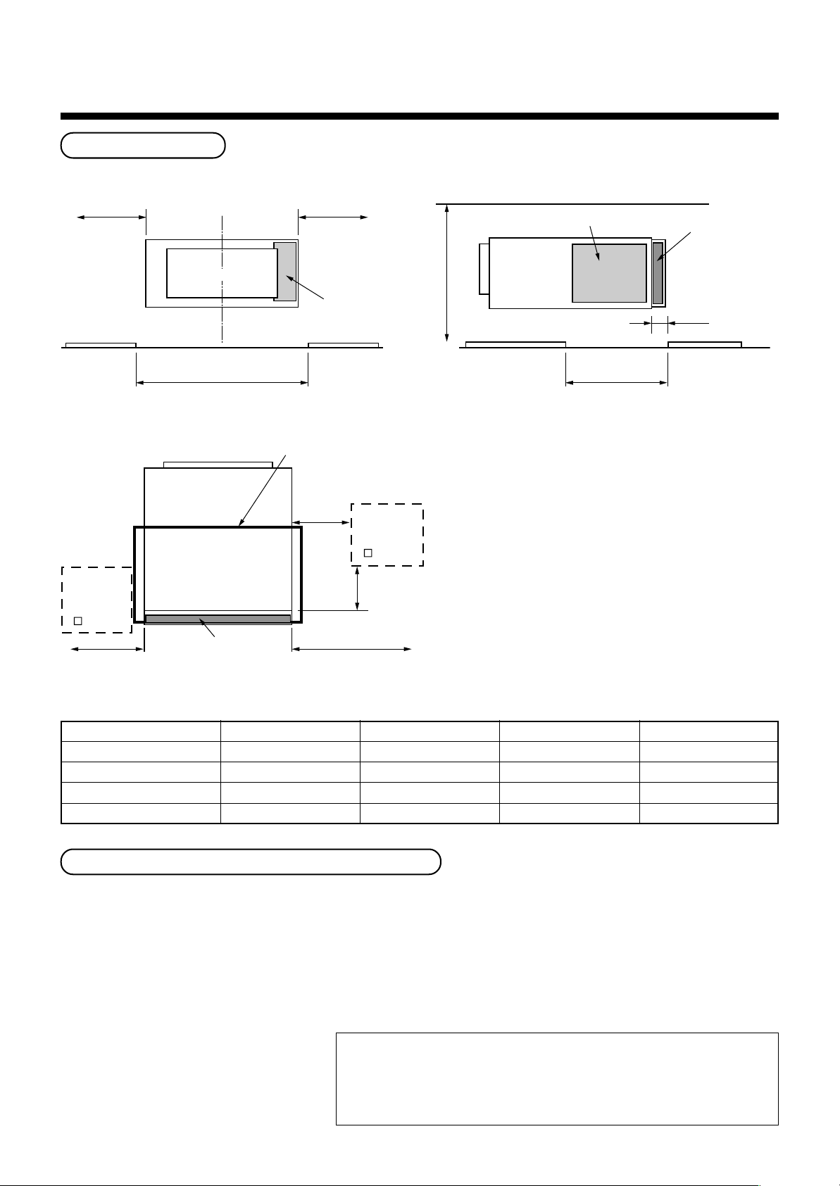
2 SELECTION OF INSTALLATION PLACE
Installation space
Reserve space required for maintenance the indoor unit and service work.
700mm *1 700mm *1
Air outlet
Electric parts box
Ceiling opening size C
Air outlet
Check port B
450mm
Air filter
700mm for maintenance of air filter 700mm for
Ceiling opening part
(150mm)
maintenance of air filter
Check port A
450mm
300mm
400mm (Min.)
Electric parts box
Ceiling opening
size D
Air filter
25mm
Notes)
*1 Be sure that space with 700mm or more is
reserved for attachment/detachment at the
taking-out direction of the air filter.
*2 Be sure to set a check port (A) for the
refrigerant piping, drain piping, maintenance of
drain pan, etc; otherwise maintenance for
devices is unavailable.
*3 If the taking-out direction of the air filter is set at
the left side, be sure to set a check port (B) at the
left side of the set for attachment/detachment of
the air filter. If there is no check port (B), the air
filter cannot be attached or detached.
*4 Be sure to set a ceiling opening for
maintenance of the electric ports such as fan
motor; otherwise maintenance for electric parts
such as fan motor is unavailable.
MODEL MMD-AP
Set width (mm)
Air filter width (mm)
Ceiling opening size C
Ceiling opening size D
0071BH to 0121BH 0151BH to 0181BH 0241BH to 0301BH 0361BH to 0561BH
550 700 1000 1350
508 655 960 (480∗2) 1310 (655∗2)
600 750 1050 1400
470 470 470 470
Installation under high-humidity atmosphere
In some cases including the rainy season, especially inside of the ceiling may become high-humidity atmosphere
(dew-point temperature: 23°C or higher).
1. Installation to inside of the ceiling with tiles on the roof
2. Installation to inside of the ceiling with slated roof
3. Installation to a place where inside of the ceiling is used for pathway to intake the outside air
• In the above cases, additionally attach the thermal insulator (Glass wool, etc.) to all positions of the air
conditioner, which come to contact with the high-humidity atmosphere. In this case, arrange the side plate
(Service plate) so
that it is easily removed.
• Apply also a sufficient thermal
insulation to the duct and connecting
part of the duct.
[Reference] Dewing test conditions
Indoor side: 27°C dry bulb temperature
24°C wet bulb temperature
Air volume: Low air volume, operation time 4 hours
6
Page 7
The lighting term setup of the filter sign (Notification
of filter cleaning) of the remote controller can be
changed according to the condition of installation.
If the room is not heated due to the installation place
or construction of the room, the detection
temperature of heating can be raised.
For setup method, refer to “Change of lighting term of
filter sign” and “To secure better effect of heating” in
the Applicable controls of this Manual.
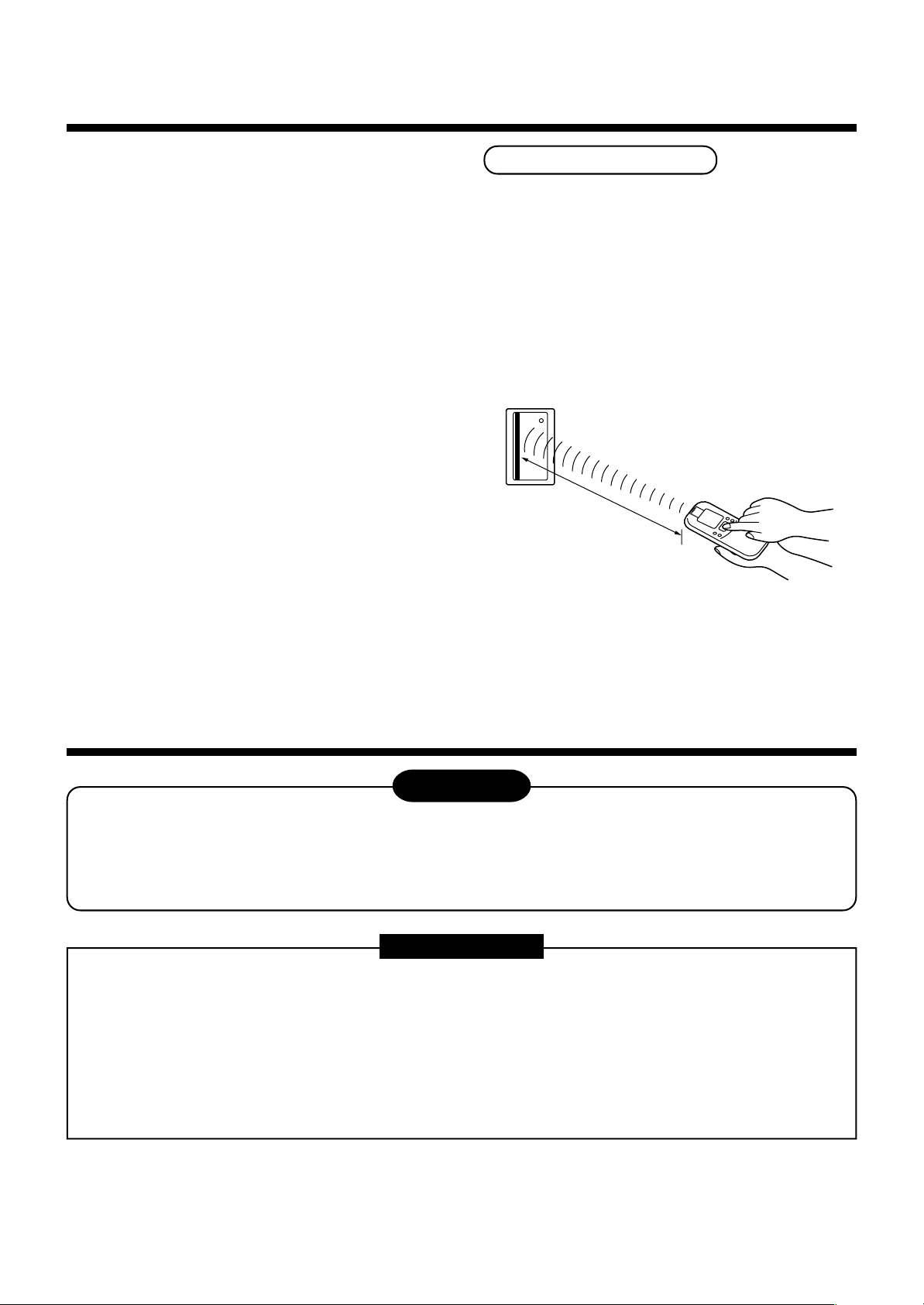
In case of wireless type
The sensor of indoor unit with wireless remote
controller can receive a signal within approx. 8m.
Based upon it, determine a place where the remote
controller is operated and the installation place of the
indoor unit.
• To prevent a malfunction, select a place where is not
influenced by a florescent light or direct sunlight.
• Two or more (Up to 6 units) indoor units with
wireless remote controller can be installed in the
same room.
Within 8m
3 INSTALLATION OF INDOOR UNIT
WARNING
Install the air conditioner certainly to sufficiently withstand the weight.
If the strength is insufficient, the unit may fall down resulting in human injury.
Perform a specified installation work to guard against strong wind or earthquake.
An incomplete installation can cause accidents by the units falling and dropping.
REQUIREMENT
Strictly comply with the following rules to prevent damage of the indoor units and human injury.
• Do not put a heavy article on the indoor unit. (Even units are packaged)
• Carry in the indoor unit as it is packaged if possible.
If carrying in the indoor unit unpacked by necessity, be sure to use buffering cloth, etc. to not damage the unit.
• To move the indoor unit, hold the hooking metals (4 positions) only.
Do not apply force to the other parts (refrigerant pipe, drain pan, foamed parts, or resin parts, etc.).
• Carry the package by two or more persons, and do not bundle it with PP band at positions other than specified.
7
Page 8
3 INSTALLATION OF INDOOR UNIT
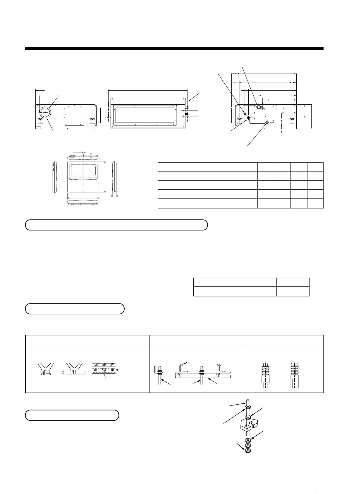
External view
Refrigerant pipe connecting port
(Gas side ØF)
129
110
6-Ø4 Tapping screw hole Ø160
• Wired remote controller (RBC-AMT21E)
Knock-out hole Ø125
(Air take-in port)
4
2.7
120
Hanging bolt pitch B
Main unit dimension A
AP0071BH, AP0091BH, AP0121BH
Refrigerant pipe connecting port
(Liquid side ØG)
AP0151BH, AP0181BH
120
16
AP0241BH, AP0271BH, AP0301BH
AP0361BH, AP0481BH, AP0561BH
Opening hole on ceiling and placing of hanging bolt
Drain pipe connecting port for vinyl chloride pipe
(Inner dia. 32, VP. 25)
Main unit dimension 800
75
41
Hanging bolt
4-M10 screw
(Arranged locally)
44
49
Ø26 Power supply, remote controller cable take-out port
Model MMD-
Hanging bolt pitch 700
50
131
50
638
41
ABFG
498
243
393
196
550 616 9.5 6.4
700 766 12.7 6.4
1000 1066 15.9 9.5
1350 1416 15.9 9.5
59
174
320
• Considering the indoor unit and the hanged-up piping/wiring work, determine the installation position and direction.
•
After installation position of the indoor unit has been determined, open a hole on the wiring and place the hanging bolt.
• For opening size of the ceiling and the hanging bolt pitch, see the external view.
• When the ceiling has already boarded, draw the drain pipe, refrigerant pipe, inter-unit wire between indoor and
outdoor units, central control system wire, and remote controller wire up to the position where pipes and wires
are connected before hanged-up the indoor unit.
The hanging bolts and nuts will be procured locally.
Hanging bolt
Nut
M10 or W3/8
M10 or W3/8
4 pieces
12 pieces
Installation of hanging bolt
Use M10 hanging bolts (4 pcs, to be local procure).
Matching to the existing structure, set pitch according to size in the unit external view as shown below.
New concrete slab
Install the bolts with insert brackets or anchor
bolts.
Reinforcing
steel
(Blade type
bracket)
(Slide type
bracket)
Anchor bolt
(Pipe hanging
anchor bolt)
Steel flame structure
Use existing angles or install new
support angles.
Hanging bolt Support angle
Hanging bolt
Hanging bolt
(W3/8 or M10)
Existing concrete slab
Use a hole-in anchors, hole-in
plugs, or a hole-in bolts.
(1)
M10 flat washer
(Accessory)
Installation of indoor unit
• Attach the nuts (M10 or W3/8: Procured locally) and
the attached washers (Ø34) to the hanging bolt.
• Put washers at up and down of T-groove of the hanging
bracket of the indoor unit to hang down the indoor unit.
• Using a level vial, check that four sides are horizontal.
(Horizontal degree: Within 5mm)
Nut
(W3/8 or M10)
Nut
(W3/8 or M10)
(1)Required those other than M10 flat washer at site.
(2)To prevent falling-off of bolt (safety), be sure to set it
just under the hanging bracket as shown in the figure.
(2)
M10 flat washer
(Accessory)
8
Page 9
Installation of remote controller (Sold separately)
As long as possible (10cm)
VP30 or more
Downward slope
1/100 or more
VP25
VP25
VP25
(Collective pipes)
For installation of the remote controller, follow to the Installation Manual attached to the remote controller.
• Do not put the remote controller on the place where is exposed to direct sunlight or near a stove, etc.
• Operating the remote controller, check the indoor unit surely receives the signal, and then install the remote
controller. (Wireless type)
• Install the remote controller 1m apart from the devices such as TV or stereo.
(Image may be disturbed or noise may be output.) (Wireless type)
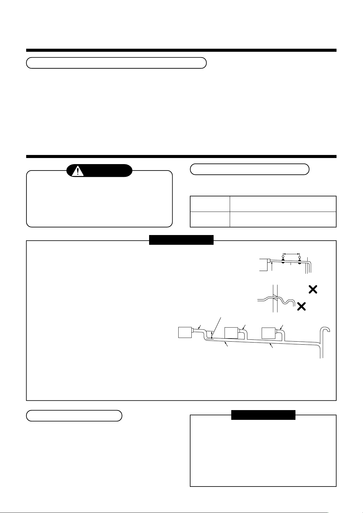
4 DRAIN PIPING WORK
CAUTION
• Following the Installation Manual, perform
the drain piping work so that water is
properly drained, and apply a heat insulation
so as not to cause a dew. Inappropriate
piping work may result in water leakage in
the room and wet of furniture.
Pipe material/Insulator and size
The following materials for piping work and insulating
process are procured locally.
Pipe material
Insulator
REQUIREMENT
• Be sure to perform heat insulation of the drain pipes of the indoor unit.
• Never forget to perform heat insulation of the connecting part with the
indoor unit. An incomplete heat insulation causes dewing.
• Set the drain pipe with downward slope (1/100 or more), and do not
make swelling or trap on the piping. It may cause an abnormal sound.
• For length of the traversing drain pipe, restrict to 20m or less.
In case of a long pipe, provide support brackets with interval of
1.5 to 2m in order to prevent waving.
• Set the collective piping as shown in the right figure.
• Do not mount an air purge pipe,
otherwise drain water spouts
out resulted in water leak.
Hard vinyl chloride pipe VP25
(Outer diameter Ø32mm)
Foamed polyethylene foam, thickness:
10mm or more
Heat
insulator
1.5m to 2m
1/100 or more
downward
Arched
shape
Trap
Support
bracket
• The hard vinyl-chloride pipe cannot be directly connected to
• Adhesive agent cannot be used for the pipe connecting port (hard socket) of the indoor unit.
Connection of drain pipe
• Connect the hard socket (Procured locally) to the
hard socket side of the attached flexible hose which
has been installed.
• Connect the drain pipes (Procured locally)
successively to the connected the hard socket.
the drain pipe connecting port of the indoor unit. For connection with
the drain pipe connecting port, be sure to fix the attached flexible hose.
Be sure to use the attached hose band for fixing, otherwise damage or water leakage of the drain pipe
connecting port is caused.
REQUIREMENT
• Using adhesive agent for vinyl chloride, connect
the hard vinyl chloride pipes certainly so that
water does not leak.
• It requires several times to dry and harden the
adhesive agent.
9
(Refer to Guide Manual of the adhesive agent.)
In this time, be sure not to apply force to the
connecting section with the drain pipes.
Page 10

220–240V ~, 50Hz
220V
~
, 60Hz
White
Black
CN34
(RED)
Black
Red
Pull out connector CN34 (Red) from P.C. board.
R(L) S(N)
4 DRAIN PIPING WORK
Drain up
When a downward grading cannot be secured on the
drain pipe, a drain-up work is possible.
• Set the height of the drain pipe within 550mm from
the bottom surface of the ceiling.
• Draw out the drain pipe within 100mm from the end
of the drain pipe connecting port of the indoor unit,
and then raise it vertically.
• After the drain pipe has been raised, set a grading so
that it is immediately bent downward.
Check the draining
After drain piping work, check that water drain is properly performed and water does not leak from the connecting
part of the pipes. In this time, check also there is no abnormal sound of the motor of the drain pump.
Be sure to check draining when installed in the heating period.
When the electric work has finished:
• Before installing a panel, pour water as shown in the following figure, check water is drained from the drain pipe
connecting port (Transparent) in COOL mode, and then check there is no water leak from the drain pipes.
100mm
or less
Indoor unit
Rising up 550mm or less
When the electric work has not finished:
• Pull out the float switch connector (3P: Red) from P.C.
board connector (CN34: Red) of the electric parts box.
(In this time, be sure to check the power is turned off.)
• Connect the single-phase 220-240V 50Hz
(or 220V 60Hz) power to the terminal blocks R (L) and
S (N). (Never apply 220-240V to (A), (B), (U1),and
(U2), otherwise a trouble of P.C. board occurs.)
• Pour water referring to the right figure.
(Amount: 1500cc to 2000cc)
• When the power is turned on, the drain pump motor
drives automatically.
Check water is drained from the drain pipe connecting
port (Transparent), and then check there is no water
leak from the drain pipes.
• After check of draining and water leak, turn off the
power supply, attach the float switch connector to the
original position (CN34) of P.C. board, and then set
the electric parts box as before.
Thermal insulating process
Insert the end of hose
up to the near of suction
port of drain pump.
Service plate
• After check of draining, apply thermal insulation surely
to the pipe connecting part.
• Give taping without clearance to the striking section of
the main unit with thermal insulator at local site.
Hard vinyl
chloride pipe
(Required at site)
Heat insulator
(Required at site)
10
Butt heat insulator without clearance.
Using tape,
fix the heat insulator.
Heat insulator
(Main unit side)
Page 11

5 REFRIGERANT PIPING
WARNING
• If refrigerant gas has leaked during the installation work, ventilate the room immediately.
• If the leaked refrigerant gas comes in contact with fire, noxious gas may generate.
• After the installation work, confirm that refrigerant gas does not leak.
• If refrigerant gas leaks into the room and flows near a fire source, such as a cooking range, noxious gas
may generate.
REQUIREMENT
When the refrigerant pipe is long, set the support brackets to fix the pipe with 2.5 to 3m intervals.
If the pipe is not fixed, abnormal sound may generate.
Be sure to use the flare nuts attached to the indoor unit or those fro R410A.
Permissible pipe length and permissible height difference
They are different according to the used outdoor unit.
For details, refer to the Installation Manual attached to the outdoor unit.
Piping material and dimensions
Piping material
Model MMD-AP
Pipe size (mm)
• Use a clean and new pipe, and check that impurity such as dust, oil, moisture, etc. does not adhere in the pipe.
Gas side
Liquid side
Pipe Forming/End Positioning
Flaring
1. Cut the pipe with a pipe cutter.
90˚
2. Insert a flare nut into the pipe, and flare the pipe.
As the flaring sizes of R410A differ from those of
refrigerant R22, the flare tools newly manufactured
for R410A are recommended.
However, the conventional tools can be used by
adjusting projection margin of the copper pipe.
Obliquity Roughness Warp
Phosphor deoxidization joint-less pipe for air conditioner
0071BH to 0121BH 0151BH to 0181BH 0241BH to 0561BH
Ø9.5 Ø12.7 Ø15.9
Ø6.4 Ø6.4 Ø9.5
• Flaring diam. meter size : A (Unit : mm)
+0
A
Outer diam. of copper pipe
6.4
9.5
12.7
15.9
In case of flaring for R410A with the conventional
*
flare tool, pull it out approx. 0.5 mm more than that
for R22 to adjust to the specified flare size.
The copper pipe gauge is useful for adjusting
projection margin size.
A
- 0.4
R410A
9.1
13.2
16.6
19.7
11
Page 12

5 REFRIGERANT PIPING
• Projection margin in flaring :
B (Unit : mm)
Rigid (Clutch type)
Outer diam. of
copper pipe
6.4
9.5
12.7
15.9
R410A tool used
R410A R22
0 to 0.5 (Same as left)
0 to 0.5 (Same as left)
0 to 0.5 (Same as left)
0 to 0.5 (Same as left)
Conventional tool used
R410A R22
1.0 to 1.5 0.5 to 1.0
1.0 to 1.5 0.5 to 1.0
1.0 to 1.5 0.5 to 1.0
1.0 to 1.5 0.5 to 1.0
Imperial (Wing nut type)
Outer diam. of copper pipe
6.4
9.5
12.7
15.9
R410A R22
1.5 to 2.0 1.0 to 1.5
1.5 to 2.0 1.0 to 1.5
2.0 to 2.5 1.5 to 2.0
2.0 to 2.5 1.5 to 2.0
Connection of refrigerant pipe
Connect all the refrigerant pipes with flare connecting
work.
• Since the atmospheric pressure only is sealed
as the sealing gas, it is not abnormal that
“Pushu…” sound is not heard when the flare
nut is removed.
• Be sure to use a double spanner for pipe
connecting work of the indoor unit.
B
• Tightening torque of flare pipe connections
Pressure of R410A is higher than that of R22 by
approx. 1.6 times.
Therefore, using a torque wrench, tighten the flare
pipe connecting sections which connect the indoor
and outdoor units of the specified tightening torque.
Incorrect connections may cause not only a gas
leak, but also a trouble of the refrigerating cycle.
REQUIREMENT
If an excessive torque is applied, the nut may
crack depending on the installation conditions.
Airtight test/Air purge, etc.
For airtight test, air purge, addition of refrigerant, and
gas leak check, follow the Installation Manual
attached to the outdoor unit.
REQUIREMENT
Be sure to use the tool such as charge hose
exclusive to R410A.
Do not turn on the power until the airtight test and
the vacuuming have finished.
(If turning on the power, the incorporated PMV is
closed fully and the period until the vacuuming
finishes elongates.)
Open fully valves of the outdoor unit
Gas leak check
Work using double spanner
• Refer to the following table for tightening torque.
Connecting pipe
outer dia. (mm)
Ø6.4
Ø9.5
Ø12.7
Ø15.9
Tightening torque
(N•m)
14 to18 (1.4 to 1.8 kgf•m)
33 to 42 (3.3 to 4.2 kgf•m)
50 to 62 (5.0 to 6.2 kgf•m)
68 to 82 (6.8 to 8.2 kgf•m)
Re-tightening
torque (N•m)
18 (1.8 kgf•m)
42 (4.2 kgf•m)
50 (5.0 kgf•m)
68 (6.8 kgf•m)
Check with a leak detector or soap water whether
gas leaks or not, from the pipe connecting section or
cap of the valve.
REQUIREMENT
Use a leak detector manufactured exclusively for
HFC refrigerant (R410A, R134a, etc.).
12
Page 13

Heat insulating process
Perform heat insulating for pipes at liquid side and
gas side separately. In cooling time, temperature at
both liquid and gas sides becomes lower.
Therefore, perform heat insulating process
sufficiently to avoid dewing.
• For heat insulator of pipe at gas side, be sure to
use one with heat-resisting temp.120°C or more.
• Using the attached heat insulating pipe, perform
heat insulating process
securely for pipe connecting part of the indoor
units without clearance.
6 ELECTRIC WORK
WARNING
REQUIREMENT
Apply the thermal insulation to the pipe connecting
section of the indoor unit securely up to the root
without exposure of the pipe.
(The pipe exposed to the outside causes water leak.)
Set notching upward.
Pipe side
(Required at the site)
Attached heat insulating pipe
1. Using the specified wires, ensure to connect the wires, and fix wires securely so that the
external strength of the wires do not transmit to the connecting part of the terminals.
Incomplete connection or fixation may cause a fire, etc.
2. Be sure to connect earth wire. (Grounding work)
Do not connect the earth wire to gas pipe, city water pipe, lightning rod, or the earth wire of telephone.
Incomplete grounding causes an electric shock.
3. For electric work, strictly follow to the Local Regulation in each country and the Installation
Manual, and use an exclusive circuit.
Capacity shortage of power circuit or incomplete installation may cause an electric shock or a fire.
CAUTION
Be sure to install an earth leakage breaker.
If an earth leakage breaker is not installed, an electric shock may be caused.
REQUIREMENT
• For power supply wiring, strictly conform to the Local Regulation in each country.
• For wiring of power supply of the outdoor units, follow to the Installation Manual of each outdoor unit.
• Never connect 220–240V power to the terminal blocks (A, B, U1, U2, X, Y, etc.) for control wiring.
(Otherwise, the system will be failed.)
• Perform the electric wiring so that it does not come to contact with the high-temperature part of the pipe.
The coating may melt resulted in an accident.
• After connecting wires to the terminal blocks, provide a trap and fix wires with the wire clamp.
• Store the refrigerant piping line and control wiring line in the same line.
• Do not turn on the power of the indoor unit until vacuuming of the refrigerant pipes completes.
• Keep a margin (Approx. 100mm) on a wire to hang down the electric parts box at servicing, etc.
13
Page 14

6 ELECTRIC WORK
Power supply specifications
Power supply cord and communication wires are procured locally.
For the power supply specifications, follow to the table below.
If capacity is little, it is dangerous because overheat or seizure may be caused.
For specifications of the power capacity of the outdoor unit and the power supply wires, refer to the Installation
Manual attached to the outdoor unit.
Power supply (*1)
Communication line
Power supply
Power supply switch/Earth leakage breaker or power supply wiring/fuse rating for
indoor units should be selected by the accummulated total current values of the indoor units.
Below 20m
Power supply wiring
Indoor/Outdoor inter-unit wiring (*2)
(2 cables)
Central control line wiring (*3)
(2 cables)
Remote controller wiring (*4)
(2 cables)
Below 50m
Wire size
Wire size
Wire size
220–240V
(Up to 1000m) Twist wire : 1.25 mm²
(Up to 2000m) Twist wire : 2.00 mm²
(Up to 1000m) Twist wire : 1.25 mm²
(Up to 2000m) Twist wire : 2.00 mm²
~ 50Hz, 220V ~ 60Hz
Twist wire : 2.0 mm²
Twist wire : 3.5 mm²
Twist wire : 0.5 to 2.0 mm²
Indoor unit power supply (*1)
• For the power supply of the indoor unit, prepare the exclusive power supply separated from that of the outdoor unit.
• Arrange the power supply, earth leakage breaker, and main switch of the indoor unit connected to the same
outdoor unit so that they are commonly used.
• Power supply cord specification : Cable 3-core 2.5mm², in conformity with Design 60245 IEC 57.
Indoor/Outdoor inter-unit wiring, Central controller wiring (*2) (*3)
• 2-core with polarity wires are used for the Indoor/Outdoor inter-unit wiring and Central controller wiring.
• To prevent noise trouble, use 2-core shield wire.
• The length of the communication line means the total length of the inter-unit wire length between indoor and
outdoor units added with the central control system wire length.
Remote controller wiring (*4)
• 2-core with non-polarity wire is used for wiring of the remote controller wiring
and group remote controllers wiring.
CAUTION
Remote controller wiring, remote
controller inter-unit wiring
Total wire length of remote controller
wiring and remote controller inter-unit
wiring = L + L1 + L2 + … Ln
Total wire length of remote controller inter-unit wiring = L1 + L2 + … Ln
Indoor unit
Remote
controller
wiring
Remote
controller
Twist wire: 0.5mm2 to 2.0mm2 × 2
In case of wired type only
In case of wireless type included
Indoor unit
L1 L2 Ln
Remote controller inter-unit wiring
Up to 500m
Up to 400m
Up to 200m
Indoor unit Indoor unit
(Max. 8 units)
The remote controller wire
(Communication line) and
AC220–240V wires cannot be
parallel to contact each other and
cannot be stored in the same
conduits. If doing so, a trouble
may be caused on the control
system due to noise, etc.
14
Page 15

Electric parts box cover
Connecting wire hole
Electric
parts box
Cable connection
R
(L)S(N)
10
10
30
70
Earth line
Connecting
cable
REQUIREMENT
• Be sure to pass the wire through the wire connection port of the indoor unit.
• Keep a margin (Approx. 100mm) on a wire to hang down the electric parts box at servicing, etc.
• The low-voltage circuit is provided for the remote controller.
• Remove the cover of the electric parts box by taking off the mounting screws (2 positions) and pushing the
hooking section. (The cover of the electric parts box remains hanged to the hinge.)
• Tighten the screws of the terminal block, and fix the wires with cord clamp attached to the electric parts box.
(Do not apply tension to the connecting section of the terminal block.)
• Be sure to set a loop for the connecting wire of the storing
part of the indoor unit electric parts; otherwise the electric
parts box cannot be drawn out in service time.
• Mount the cover of the electric parts box without
pinching wires.
Inter-unit cable
between indoor
and outdoor units
R(L) S(N)
U1 U1 A B
Cable cramp Power supply cable
Remote controller wire
15
Page 16

6 ELECTRIC WORK
Remote controller wiring
• Strip off approx. 14mm cover of the wire to be connected.
• Twist wire of the remote controller to be connected with wire of the remote controller unit (or sensor), and pressfit them with a wire joint. (Wire joints (White: 2 pieces) are included in the accessory of the main remote
controller (sold separately) or wireless remote controller kit (sold separately).)
• As the remote controller wire has no polarity, there is no problem if connections to indoor unit terminal blocks A
and B are reversed.
<Wiring diagram>
Terminal block
for remote controller
wiring of indoor unit
A
B
Remote controller wire
(Local procure)
Wiring between indoor and outdoor units
Approx. 200mm
W
Connecting
part
W : White
B : Black
Remote
B
Wire from remote controller unit
or sensor
controller unit
or sensor part
Remote controller wiring
Wire from remote
controller or sensor
Wire joint
Outdoor power supply
3-phase
380–415V, 50Hz
380V, 60Hz
Central control line wire
Power supply
220–240V
220V
Indoor power supply
220–240V
220V ~ 60Hz
~
50Hz
Earth leakage breaker
~
50Hz
~
60Hz
Remote controller,
for central control, etc.
Earth leakage breaker
Switch
Header unit Follower unit
Connection of shield
wire closed terminal
(Open)
Indoor/Outdoor inter-unit wire
Connection of shield
wire closed terminal
NOTE
An outdoor unit connected
with indoor/outdoor inter-unit
wire becomes automatically
the header unit.
(Earth)
Earth
Inter-unit wire between outdoor units
Pull box
(Earth)
Indoor unit
(Remote controller group operation)
Address setup
Set up the addresses according to the Installation Manual attached to the outdoor unit.
16
Page 17

7 APPLICABLE CONTROLS
NOTIFICATION
When using the equipment at the first time, it will take a lot of time that the remote controller accepts an
operation after power was on. However, it is not a trouble.
• Automatic address
• While automatic addressing, the operation cannot be performed on the remote controller.
• For automatic addressing, Max. 10 minutes (generally, approx. 5 minutes) are required.
• When power will be turned on after finish of automatic addressing;
• It will require Max. 10 minutes (generally, approx. 3 minutes) that outdoor unit starts operation after power
was on.
As all have been set to [Standard] at the shipment, change the setup of the indoor unit if necessary
To change the setup, use the main remote controller (wired remote controller).
* The setup change for wireless remote controller, sub remote controller, or remote controller-less system
(Central control remote controller only is provided.) is impossible.
In these cases, prepare and mount a separate main remote controller.
Exchange of applicable control setup
Basic operation procedure for setup exchange
Change the setup while operation of the equipment stops.
(Be sure to stop the operation of a set.)
Procedure
SET
, CL , and buttons simultaneously for 4 seconds or more, after a while, the display part
button has been pushed, the operation
UNIT
button, the indoor unit No. in the group control is displayed successively.
1
2
When pushing
flashes as shown in the figure. Check that the displayed item code is [10].
• If the item code indicates other than [10], push
the display, and then retry the operation from the first step.
(For some time after
of the remote controller cannot be accepted.)
(In a group control, the firstly displayed
indoor unit No. becomes the center unit.) (* The display changes according to the indoor unit model.)
Every pushing
Select an indoor unit of which setup to be changed.
In this time, the position of the indoor unit of which setup to be changed can be
confirmed because the fan and the flap of the selected indoor unit work.
Using , buttons of set temperature, specify the item code [**].
3
4
Using , buttons of timer time, select set data [
4
6
1
Description
button to erase
].
****
UNIT No.
R.C. No.
UNIT
CL
SET
*
** **
CODE No.
UNIT No.
R.C. No.
UNIT No.
** **
R.C. No.
2
3
5
CODE No.
CODE No.
**
5
6
SET
Push
• To change the setup of an indoor unit other than the selected one, start operation from Procedure
• To change the setup of another setup in the selected indoor unit, start operation from Procedure
Pushing
When the setup finished, push button. (The setup is determined.)
Pushing
normal stop status.
(For some time after
the remote controller cannot be accepted.)
button. In this time, if the display changes from flashing to lighting, the setup completes.
CL
button clears the set up contents which have been already set. In this case, retry from Procedure 2.
button deletes the display and returns the status to
button has been pushed, the operation of
17
.
2
.
3
Page 18

7 APPLICABLE CONTROLS
Setup of outside static pressure
Be sure to set up a tap change based upon the
resistance (outside static pressure) of the duct to be
connected.
To set up a tap change, follow to the basic operation
procedure (1 → 2 → 3 → 4 → 5 → 6 ).
• Specify [5d] to the item code in procedure 3 .
• For the setup data of procedure 4 , select a setup
data of the outside static pressure to be set up from
<Change on wired remote controller>
Setup data
0000
0001
0003
0006
40Pa Standard (At shipment)
70Pa *1 High static pressure 1
100Pa *2 High static pressure 2
20Pa High static pressure
*1: 65Pa for Model AP0481BH, AP0561BH
*2: 90Pa for Model AP0481BH, AP0561BH
Outside static pressure
the following table.
In case of remote controller-less (Group control)
For setup to the high ceiling, there is selecting method by exchanging the short plugs on the indoor
microcomputer P.C. board as shown in the following table other than selecting method by standard wired remote
controller
(sold separately). Utilize this method for remote controller-less (Group control) case.
∗ However, when the setup to high ceiling has been once exchanged, it is required for returning it to 0000 to
change the short plug to the standard (at shipment) position and rewrite data to the setup data 0000 from the
wired remote controller sold separately though setup to 0001 or 0003 are freely available.
To incorporate a filter sold separately for reference
• Select by exchange of short plugs on the indoor
microcomputer P.C. board.
Short plug position
Filter sold separately
Standard filter
(At shipment)
Super long life filter
High-efficiency filter (65%)
High-efficiency filter (90%)
Short
CN112 CN111 CN110
CN112 CN111 CN110
CN112 CN111 CN110
Open
Set data
0000
0001
0003
• Short plug position
(CN112, CN111, CN110 from the left)
18
Page 19

Change of lighting term of filter sign
Group control
According to the installation condition, the lighting term
of
the filter sign (Notification of filter cleaning) can be
changed.
Follow to the basic operation procedure
(1 → 2 → 3 → 4 → 5 → 6 ).
• For the item code in Procedure 3 , specify [01].
• For the [Set data] in Procedure 4 , select the setup data
of filter sign lighting terme from the following table.
Setup data
0000
0001
0002
0003
0004
Filter sign lighting term
None
150H
2500H (At shipment from factory)
5000H
10000H
To secure better effect of heating
In a group control, a remote controller can control
up to maximum 8 units.
• For cabling procedure and cables of the individual
line (Identical refrigerant line) system, refer to
“Electric work” in this Manual.
• Cabling between indoor units in a group is
performed in the following procedure.
Connect the indoor units by connecting the
remote controller inter-unit cables from the
remote controller terminal blocks (A, B) of the
indoor unit connected with a remote controller to
the remote controller terminal blocks (A, B) of the
other indoor unit. (No polarity)
• For address setup, refer to the Installation Manual
attached to the outdoor unit.
When it is difficult to obtain satisfactory heating due to
installation place of the indoor unit or structure of the room,
the detection temperature of heating can be raised.
Also use a circulator, etc. to circulate heat air near the
ceiling.
Follow to the basic operation procedure
(1 → 2 → 3 → 4 → 5 → 6 ).
• For the item code in Procedure 3 , specify [06].
• For the set data in Procedure 4 , select the setup data
of shift value of detection temperature to be set up
from the table below.
Setup data
0000
0001
0002
0003
0004
0005
Detection temp shift value
No shift
+1°C
+2°C (At shipment from factory)
+3°C
+4°C
+5°C
0006
+6°C
19
Page 20

8 TEST RUN
Before test operation
• Before turning on the power supply, carry out the following items.
1) Using 500V-megger, check there is 1MΩ or more between the
terminal block of the power supply and the earth.
If 1MΩ or less is detected, do not run the unit.
2) Check that all the valves of the outdoor unit are fully opened.
• Never push the electromagnetic contactor to carry out a forced test operation.
(It is very dangerous because a protective device does not work.)
To protect the compressor at
starting time, keep power-ON
condition before 12 hours or more.
WARNING
How to execute test operation
• To carry out a fan operation in a single indoor unit, turn off the power once, short CN72 on P.C. board, and then
turn on the power again. (Start the unit in FAN mode.)
In this case, do not forget to clear short-circuit of CN72 after test operation.
• Using the remote controller, check the operation in the usual operation.
For the operation procedure, refer to the attached Owner’s Manual.
A forced test operation can be executed in the following procedure under condition of thermo-OFF of room
temperature. In order to prevent a serial operation, the forced test operation is released after 60 minutes and
returns to the usual operation.
NOTE
Do not use a forced operation in cases other
than test operation because it applies an
excessive load to the air conditioner.
In case of wired remote controller
Procedure
Keep button pushed for 4 seconds or more.
1
2
3
[TEST] is displayed on the display part and the selection
of mode in the test mode is permitted.
Push button.
Using button, select the operation mode, [COOL] or [HEAT].
• Do not run the air conditioner in a mode other than [COOL] or [HEAT].
• The temperature controlling function does not work during test operation.
• The detection of error is performed as usual.
1, 5
Description
SET
2, 4
3
UNIT
CL
TEST
4
5
After the test operation, push button to stop the operation.
(Display part is same as procedure
Push button to cancel (release from) the test operation mode.
([TEST] disappears on the display part and the status returns to
a normal stop status.)
)
1
20
Page 21

In case of wireless remote controller
Procedure
1
2
3
4
Description
Remove a small screw which fixes the nameplate of the receiver unit.
Remove the nameplate of the sensor section by inserting a minus screwdriver, etc into the notch at the
bottom of the plate, and set the Dip switch to [TEST RUN ON].
Execute a test operation with button on the wireless remote controller.
• , , and LED flash during test operation.
• Under status of [TEST RUN ON], the temperature adjustment from the wireless remote controller is invalid.
Do not use this method in the operation other than test operation because the equipment is damaged.
Use either COOL or HEAT operation mode for a test operation.
* The outdoor unit does not operate approx. 3 minutes after power-ON and operation stop.
After the test operation finished, stop the air conditioner from the wireless remote controller, and return Dip
switch of the receiver section as before.
(A 60-minutes timer clearing function is attached to the receiver section in order to prevent a continuous test
operation.)
Receiver unit
Spacer
M4 × 25 screw
(2 pieces)
Small screw
Notch
Nameplate
In case of abnormal test operation
• When the test operation has not normally finished, refer to the check No. and the check position in the
“9 TROUBLESHOOTING”.
• If the test operation has been executed before installation of the outside duct, a protective control works
resulted in stop of the air conditioner, and then an error code [P12] may be output. However it is not a trouble.
(The current limit control works in the characteristics of DC motor which is adopted in the indoor fan motor of this model.)
Carry out a test operation by setting the air volume tap to small or closing the discharge port before installation
of the outside duct.
• Be sure also to stop the fan in exchange of high-performance filter or opening of the service board.
After the test operation has finished, reset necessarily the leak breaker of the indoor unit.
21
Page 22

9 TROUBLESHOOTING
3
Confirmation and check
When a trouble occurred in the air conditioner, the check
code and the indoor unit No. appear on the display part of
the remote controller.
The check code is only displayed during the operation.
If the display disappears, operate the air conditioner
according to the following “Confirmation of error history”
for confirmation.
Confirmation of error history
When a trouble occurred on the air conditioner, the error
history can be confirmed with the following procedure.
(The error history is stored in memory up to 4 errors.)
This history can be confirmed from either operating status
or stop status.
Check code
Check code
SET
1
CODE No.
CODE No.
UNIT No.
UNIT No.
R.C. No.
R.C. No.
Indoor unit No. in which
Indoor unit No. in which
an error occurred
an error occurred
UNIT
CL
2
Procedure
1
2
3
Description
When pushing
If [Service Check] is displayed, the mode enters in the error
history mode.
• [01: Order of error history] is displayed in CODE No. window.
• [Check Code] is displayed in CHECK window.
• [Indoor unit address in which an error occurred] is displayed
in UNIT No.
Every pushing , buttons, the error history stored in the memory is displayed in order.
The numbers in CODE No. indicates CODE No. [01] (Latest) → [04] (Oldest).
CAUTION
Do not push
After confirmation, push button to return to the usual display.
and buttons simultaneously for 4 seconds or more, the right display appears.
SET
UNIT No.
R.C. No.
button because all the error history of the indoor unit will be deleted.
CL
CODE No.
22
Page 23

Check method
On the remote controller (Main remote controller, Central control remote controller) and the interface P.C. board
of the outdoor unit (I/F), a check display LCD (Remote controller) or 7-segment display (on the outdoor interface
P.C. board) to display the operation is provided. Therefore the operation status can be known. Using this selfdiagnosis function, a trouble or position with error of the air conditioner can be found as shown in the table below.
Check code list
The following list shows each check code. Find the check contents from the list according to part to be checked.
• In case of check from indoor remote controller: See “Main remote controller display” in the list.
• In case of check from outdoor unit: See “Outdoor 7-segment display” in the list.
• In case of check from AI-NET central control remote controller: See “AI-NET central control display” in the list.
•
In case of check from indoor unit with wireless remote controller: See “Sensor block display of receiving unit” in the list.
AI-NET : Artificial Intelligence.
IPDU : Intelligent Power Drive Unit
¡ : Lighting,
ALT. : Flashing is alternately when there are two flashing LED.
: Flashing, l : Goes off
¤
SIM : Simultaneous flashing when there are two flashing LED.
Wireless remote controller
Sensor block display
of receiving unit
Operation
Timer Ready Flash
ll
¤
ll
¤
ll
¤
ll
ll
ll
¤
¤
¤
¤
ll
ll
¤
ll
ll
ll
ll
ll
ll
ll
¤
¤
¤
ll
ll
ll
ll
¤
¤
ll
¤
¤
¤
¤
¤
¤
¤
Communication error between indoor and
remote controller
(Detected at remote controller side)
Remote controller transmission error
Communication error between indoor and
remote controller (Detected at indoor side)
Communication circuit error between indoor/
outdoor (Detected at indoor side)
Decrease of No. of indoor units
Communication circuit error between indoor/
outdoor (Detected at outdoor side)
Duplicated indoor addresses
Duplicated main remote controllers
Communication error between indoor MCU
Automatic address start error
Indoor is nothing during automatic addressing
Capacity over / No. of connected indoor units
Communication error between indoor units
Outdoor header units quantity error
Other line connected during automatic
address
Sending error in communication between
outdoor units
Duplicated follower outdoor addresses
Decrease of No. of connected outdoor units
Follower outdoor unit error
IPDU communication error
Check code name
Judging device
Remote controller
Remote controller
Indoor
Indoor
I/F
I/F
Indoor / I/F
Remote controller
Indoor
I/F
I/F
I/F
Indoor
I/F
I/F
I/F
I/F
I/F
I/F
I/F
Main
remote
controller
display
E01
E02
E03
E04
E06
—
E08
E09
E10
E12
E15
E16
E18
E19
E20
E23
E25
E26
E28
E31
Terminology
Check code
Outdoor 7-segment display
Auxiliary code
——
——
——
——
No. of indoor units in which
E06
sensor has been normally
received
E07 —
E08 Duplicated indoor addresses
——
——
01: Indoor/Outdoor
E12
E15 —
E16
E19
E20
E23 —
E25 —
E26
E28 Detected outdoor unit number
E31 04: Fan IPDU error
communication
02: Communication between
outdoor units
00: Capacity over
~:No. of connected units
01
——
00: Header is nothing
02: Two or more header units
01: Outdoor of other line
connected
02: Indoor of other line
connected
No. of outdoor units which
received signal normally
01: IPDU1 error
02: IPDU2 error
03: IPDU1, 2 error
05: IPDU + Fan IPDU error
06: IPDU2 + Fan IPDU error
07: All IPDU error
AI-NET central
control display
—
—
97
04
04
—
96
99
CF
42
42
89
97, 99
96
42
15
15
15
d2
CF
23
Page 24

9 TROUBLESHOOTING
Main
remote
controller
display
F01
F02
F03
F04
F05
F06
F07
F08
F10
F12
F13
F15
F16
F23
F24
F29
F31
H01
H02
H03
H04
H06
H07
H08
H14
H16
L03
L04
L05
L06
L07
L08
L09
L10
L20
L28
L29
L30
—
Check code
Outdoor 7-segment display
Auxiliary code
——
——
——
F04 —
F05 —
F06 —
F07 —
F08 —
——
F12 —
01: Comp. 1 side
F13
02: Comp. 2 side
F15 —
F16 —
F23 —
F24 —
——
F31 —
01: Comp. 1 side
H01
02: Comp. 2 side
01: Comp. 1 side
H02
02: Comp. 2 side
01: Comp. 1 side
H03
02: Comp. 2 side
H04 —
H06 —
H07 —
01: TK1 sensor error
02: TK2 sensor error
H08
03: TK3 sensor error
04: TK4 sensor error
H14 —
01: TK1 oil circuit system error
02: TK2 oil circuit system error
H16
03: TK3 oil circuit system error
04: TK4 oil circuit system error
——
L04 —
——
L06 No. of indoor units with priority
——
L08 —
——
L10 —
L20 —
L28 —
01: IPDU1 error
02: IPDU2 error
03: IPDU3 error
L29 04: Fan IPDU error
05: IPDU1 + Fan IPDU error
06: IPDU2 + Fan IPDU error
07: All IPDU error
L30 Detected indoor address
L31 —
AI-NET central
control display
0F
0d
93
19
A1
18
18
1b
OC
A2
43
18
43
43
43
12
1C
IF
1d
17
44
20
d7
d4
44
d7
96
96
96
96
99
99
46
88
98
46
CF
b6
—
Wireless remote controller
Sensor block display
of receiving unit
Operation
Timer Ready Flash
ALT
¤
¤
¤
¤
¤
¤
¤
¤
¤
l
¡
l
l
l
l
l
¡
¡
¡
¡
¡
—
l
l
l
¡
¡
¡
¡
¡
l
¡
¡
¡
¡
¡
¡
l
¡
l
l
l
l
l
l
l
l
l
¤
¤
¤
¤
¤
¤
¤
¤
¤
¤
¤
¤
ALT
ALT
ALT
ALT
ALT
ALT
ALT
ALT
ALT
ALT
ALT
ALT
ALT
ALT
SIM
SIM
SIM
SIM
SIM
SIM
SIM
SIM
SIM
SIM
SIM
SIM
SIM
SIM
¤¤
¤¤
¤¤
¤¤
¤¤
¤¤
¤¤
¤¤
¤¤
¤¤
¤¤
¤¤
¤¤
¤¤
¤¤
¤¤
¤¤
l
l
l
l
l
l
l
l
l
¤
¤
¤
¤
¤
¤
¤
¤
¤
¤
¤
¤
Check code name
Indoor TCJ sensor error
Indoor TC2 sensor error
Indoor TC1 sensor error
TD1 sensor error
TD2 sensor error
TE1 sensor error
TL sensor error
TO sensor error
Indoor TA sensor error
TS1 sensor error
TH sensor error
Outdoor temp. sensor miscabling (TE, TL)
Outdoor pressure sensor miscabling (Pd, Ps)
Ps sensor error
Pd sensor error
Indoor other error
Indoor EEPROM error
Compressor break down
Magnet switch error
Overcurrent relay operation
Compressor trouble (lock)
Current detect circuit system error
Comp 1 case thermo operation
Low pressure protective operation
Oil level down detective protection
Oil level detective temp sensor error
Comp 2 case thermo operation
Oil level detective circuit error
Magnet switch error
Overcurrent relay operation
Indoor center unit duplicated
Outdoor line address duplicated
Duplicated indoor units with priority
(Displayed in indoor unit with priority)
Duplicated indoor units with priority
(Displayed in unit other than indoor unit with
priority)
Group line in individual indoor unit
Indoor group/Address unset
Indoor capacity unset
Outdoor capacity unset
Duplicated central control addresses
Over No. of connected outdoor units
No. of IPDU error
Indoor outside interlock
Extended I/C error
Judging device
Indoor
Indoor
Indoor
I/F
I/F
I/F
I/F
I/F
Indoor
I/F
IPDU
I/F
I/F
I/F
I/F
Indoor
I/F
IPDU
MG-SW
Overcurrent relay
IPDU
IPDU
I/F
I/F
I/F
I/F
I/F
I/F
MG-SW
Overcurrent relay
Indoor
I/F
I/F
I/F
Indoor
Indoor, I/F
Indoor
I/F
AI-NET, Indoor
I/F
I/F
Indoor
I/F
24
Page 25

Main
remote
controller
display
P01
P03
P04
P05
P07
P10
P12
P13
P15
P17
P19
P20
P22
P26
P29
P31
—
—
—
Check code
Outdoor 7-segment display
Auxiliary code
——
P03 —
01: Comp. 1 side
P04
02: Comp. 2 side
01: Phase-missing detection
P05
02: Phase error
01: Comp. 1 side
P07
02: Comp. 2 side
P10 Detected indoor address
——
P13 —
01: TS condition
P15
02: TD condition
P17 —
P19 Detected outdoor unit number
P20 —
0 : IGBT short
: Fan motor position
1
detective circuit error
: Fan motor trouble
3
P22
P26
P29
P31 —
——
——
——
: TH sensor temp. error
C
(Heat sink overheat)
: TH sensor error
D
: Vdc output error
E
01: Comp. 1 side
02: Comp. 2 side
01: Comp. 1 side
02: Comp. 2 side
AI-NET central
control display
11
1E
21
AF
IC
Ob
11
47
AE
bb
O8
22
1A
14
16
47
b7
97
99
Wireless remote controller
Sensor block display
of receiving unit
Operation
Timer Ready Flash
l
¤¤
l
¤
l
¤
l
¤
l
¤
l
¤¤
l
¤¤
l
¤¤
l
¤
l
¤
l
¤
l
¤
l
¤
l
¤
l
¤
l
¤
By alarm device ALT
—
—
ALT
ALT
¤
ALT
¤
ALT
¤
ALT
¤
ALT
ALT
ALT
ALT
¤
ALT
¤
ALT
¤
ALT
¤
ALT
¤
ALT
¤
ALT
¤
ALT
¤
Check code name
Indoor fan motor error
Discharge temp. TD1 error
High-pressure SW system operation
Phase-missing detection /Phase error
Heat sink overheat error
Indoor overflow error
Indoor fan motor error
Outdoor liquid back detection error
Gas leak detection
Discharge temp. TD2 error
4-way valve inverse error
High-pressure protective operation
Outdoor fan IPDU error
G-TR short protection error
Comp position detective circuit system error
Other indoor unit error
(Group terminal unit error)
Error in indoor group
AI-NET communication system error
Duplicated network adaptors
Judging device
Indoor
I/F
IPDU
I/F
IPDU, I/F
Indoor
Indoor
I/F
I/F
I/F
I/F
I/F
IPDU
IPDU
IPDU
Indoor
AI-NET
AI-NET
AI-NET
Error detected by TCC-LINK central control device
Central
control
device
indication
C05
C06
C12
P30
Check code
Outdoor 7-segment display
Auxiliary code
——
——
——
Differs according to error contents of unit with occurrence of alarm
——
AI-NET central
control display
—
—
—
Wireless remote controller
Sensor block display
of receiving unit
Operation
Timer Ready Flash
(L20 is displayed.)
Terminology
TCC-LINK : TOSHIBA Carrier Communication Link.
25
Check code name
—
—
—
Sending error in TCC-LINK central
control device
Receiving error in TCC-LINK
central control device
Batch alarm of general-purpose
equipment control interface
Group control branching unit error
Duplicated central control addresses
Judging device
TCC-LINK
TCC-LINK
General-purpose equipment
I/F
TCC-LINK
Page 26

9 TROUBLESHOOTING
New check code
1. Difference between the new check code and the current system
The displaying method of the check code changes in this model and after.
Used characters
Characteristics of
code classification
Block display
Check code in current system
Hexadecimal notation, 2 digits
Few classification of communication/incorrect setup system
Indoor P.C. board, Outdoor P.C. board, Cycle,
Communication
Alphabet + Decimal notation, 2 digits
Many classification of communication/incorrect setup system
Communication/Incorrect setup (4 ways), Indoor protection,
Outdoor protection, Sensor, Compressor protection, etc.
New check code
<Display on wired remote controller>
• [ ] goes on.
• [UNIT No.] + Check code + Operation lamp (Green) flash.
<Display on sensor part of wireless>
• Block display of combination of [ ] [ ] [ ]
<Display on indicator on wireless remote controller
receiver part>
• Unit No. and check code are displayed.
• In a case of error with auxiliary code, check code and
auxiliary code are displayed alternately.
→
Display
A
C
E
F
H
J
L
P
Classification
Unused
Central control system error
Communication system error
Each sensor error (Failure)
Compressor protective system error
Unused
Setup error, Other errors
Protective device operation
2. Special mention
1) If this model is connected to AI-NET by network adaptor, the different check codes are displayed on the
main remote controller (New check code display on new remote controller) and AI-NET central control
remote controller (Current system check code display on the current system central control remote
controller).
2) The check code is displayed only while the air conditioner is operating (Remote controller start button ON).
When the air conditioner stops and the error is cleared, the check code display on the remote controller
also disappears. However, if the error continues after stop of the operation, the check code is immediately
displayed with restarting.
OC
AI-NET central control
remote controller
Network
adaptor
AI-NET WORK bus
Indoor unit
F10
Main
remote controller
26
Page 27

10 MAINTENANCE
1,
2
3
UNIT
CODE No.
SET
CL
For maintenance, be sure to turn off the main power switch.
CAUTION
Do not handle the buttons with wet hands; otherwise an electric shock may be caused.
<Daily maintenance>
Cleaning of air filter
1 If is displayed on the remote controller,
contact to service on maintenance
professional to cleaning the air filter.
2 Clogging of the air filter decreases cooling/
heating efficiency.
3 After cleaning, push .
display disappears.
[Concealed Duct Type]
1 Take out the air filter.
• Push the extrusion of the air filter to inside and pull out it to
take out the air filter.
2 Cleaning with water or vacuum cleaner
• If dirt is heavy, clean the air filter by tepid water with neutral
detergent or water.
• After cleaning with water, dry the air filter sufficiently in a
shade place.
3 Mount the air filter.
4 Push .
• display disappears.
Air filter
27
Page 28

WARNINGS ON REFRIGERANT LEAKA GE
Check of Concentration Limit
The room in which the air conditioner is to be
installed requires a design that in the event of
refrigerant gas leaking out, its concentration will not
exceed a set limit.
The refrigerant R410A which is used in the air
conditioner is safe, without the toxicity or combustibility
of ammonia, and is not restricted by laws to be imposed
which protect the ozone layer. However, since it
contains more than air, it poses the risk of suffocation if
its concentration should rise excessively. Suffocation
from leakage of R410A is almost non-existent. With the
recent increase in the number of high concentration
buildings, however, the installation of multi air
conditioner systems is on the increase because of the
need for effective use of floor space, individual control,
energy conservation by curtailing heat and carrying
power etc.
Most importantly, the multi air conditioner system is able
to replenish a large amount of refrigerant compared with
conventional individual air conditioners. If a single unit of
the multi conditioner system is to be installed in a small
room, select a suitable model and installation procedure
so that if the refrigerant accidentally leaks out, its
concentration does not reach the limit (and in the event
of an emergency, measures can be made before injury
can occur).
In a room where the concentration may exceed the limit,
create an opening with adjacent rooms, or install
mechanical ventilation combined with a gas leak
detection device.
The concentration is as given below.
Total amount of refrigerant (kg)
Min. volume of the indoor unit installed room (m³)
≤ Concentration limit (kg/m³)
The concentration limit of R410A which is used in multi
air conditioners is 0.3kg/m³.
NOTE 1 :
If there are 2 or more refrigerating systems in a single
refrigerating device, the amounts of refrigerant should
be as charged in each independent device.
e.g., charged
amount (10kg)
Room A Room B Room C Room D Room E Room F
For the amount of charge in this example:
The possible amount of leaked refrigerant gas in
rooms A, B and C is 10kg.
The possible amount of leaked refrigerant gas in
rooms D, E and F is 15kg.
Outdoor unit
e.g.,
charged amount (15kg)
Indoor unit
Important
NOTE 2 :
The standards for minimum room volume are as follows.
(1) No partition (shaded portion)
(2) When there is an effective opening with the adjacent
room for ventilation of leaking refrigerant gas
(opening without a door, or an opening 0.15% or
larger than the respective floor spaces at the top or
bottom of the door).
Outdoor unit
Refrigerant piping
Indoor unit
(3) If an indoor unit is installed in each partitioned room
and the refrigerant piping is interconnected, the
smallest room of course becomes the object. But
when a mechanical ventilation is installed
interlocked with a gas leakage detector in the
smallest room where the density limit is exceeded,
the volume of the next smallest room becomes the
object.
Refrigerant piping
Outdoor unit
Very
small
room
Small
room
Mechanical ventilation device - Gas leak detector
Medium
room
Large room
NOTE 3 :
The minimum indoor floor area compared with the
amount of refrigerant is roughly as follows:
(When the ceiling is 2.7m high)
40
Range below the
35
m²
density limit
of 0.3 kg/m³
30
(countermeasures
not needed)
25
20
15
10
5
Min. indoor floor area
0
10 20 30
Total amount of refrigerant
Range above
the density limit
of 0.3 kg/m³
(countermeasures
needed)
Indoor unit
kg
Page 29

CONFIRMATION OF INDOOR UNIT SETUP
Prior to delivery to the customers, check the address and setup of the indoor unit, which has been installed in this
time and fill the check sheet (Table below). Deta of four units can be entered in this check sheet. Copy this sheet
according to the No. of the indoor units. If the installed system is a group control system, use this sheet by entering each line system into each installation manual attached to the other indoor units.
REQUIREMENT
This check sheet is required for maintenance after installation. Be sure to fill this sheet and then pass this
Installation Manual to the customers.
Indoor unit setup check sheet
Indoor unit Indoor unit Indoor unit Indoor unit
Room name Room name Room name Room name
Model Model Model Model
Check indoor unit address. (For check method, refer to Applicable controls in this sheet.)
* In case of a single system, it is unnecessary to enter the indoor address. (Item code: Line [12], Indoor [13], Group [14], Central control [03] )
Line Indoor Group Line Indoor Group Line Indoor Group Line Indoor Group
Central control address Central control address Central control address Central control address
Various setup Various setup Various setup Various setup
Have you changed high ceiling setup? If not, fill check mark [×] in [NO CHANGE], and fill check mark [×] in [ITEM] if changed, respectively.
(For check method, refer to Applicable controls in this sheet.) * In case of replacement of short plugs on indoor microcomputer P.C. board, setup is automatically changed.
High ceiling setup High ceiling setup High ceiling setup High ceiling setup
o NO CHANGE o NO CHANGE o NO CHANGE o NO CHANGE
o STANDARD [0000] o STANDARD [0000] o STANDARD [0000] o STANDARD [0000]
o HIGH CEILING 1 [0001] o HIGH CEILING 1 [0001] o HIGH CEILING 1 [0001] o HIGH CEILING 1 [0001]
o HIGH CEILING 3 [0003] o HIGH CEILING 3 [0003] o HIGH CEILING 3 [0003] o HIGH CEILING 3 [0003]
Have you changed lighting time of filter sign? If not, fill check mark [×] in [NO CHANGE], and fill check mark [×] in [ITEM] if changed, respectively.
(For check method, refer to Applicable controls in this sheet.)
o NO CHANGE o NO CHANGE o NO CHANGE o NO CHANGE
o NONE [0000] o NONE [0000] o NONE [0000] o NONE [0000]
o 150H [0001] o 150H [0001] o 150H [0001] o 150H [0001]
o 2500H [0002] o 2500H [0002] o 2500H [0002] o 2500H [0002]
o 5000H [0003] o 5000H [0003] o 5000H [0003] o 5000H [0003]
o 10000H [0004] o 10000H [0004] o 10000H [0004] o 10000H [0004]
Have you changed detected temp. shift value? If not, fill check mark [×] in [NO CHANGE], and fill check mark [×] in [ITEM] if changed, respectively.
(For check method, refer to Applicable control in this sheet.)
o NO CHANGE o NO CHANGE o NO CHANGE o NO CHANGE
o NO SHIFT [0000] o NO SHIFT [0000] o NO SHIFT [0000] o NO SHIFT [0000]
o +1°C [0001] o +1°C [0001] o +1°C [0001] o +1°C [0001]
o +2°C [0002] o +2°C [0002] o +2°C [0002] o +2°C [0002]
o +3°C [0003] o +3°C [0003] o +3°C [0003] o +3°C [0003]
o +4°C [0004] o +4°C [0004] o +4°C [0004] o +4°C [0004]
o +5°C [0005] o +5°C [0005] o +5°C [0005] o +5°C [0005]
o +6°C [0006] o +6°C [0006] o +6°C [0006] o +6°C [0006]
Incorporation of parts sold separately Incorporation of parts sold separately Incorporation of parts sold separately Incorporation of parts sold separately
Have you incorporated the following parts sold separately? If incorporated, fill check mark [×] in each [ITEM].
(When incorporating, the setup change is necessary in some cases. For setup change method, refer to Installation Manual attached to each part sold separately.)
o Standard panel o Standard panel o Standard panel o Standard panel
o Super long life filter o Super long life filter o Super long life filter o Super long life filter
o Others ( ) o Others ( ) o Others ( ) o Others ( )
o Others ( ) o Others ( ) o Others ( ) o Others ( )
(Item code [5d]) (Item code [5d]) (Item code [5d]) (Item code [5d])
Filter sign lighting time Filter sign lighting time Filter sign lighting time Filter sign lighting time
(Item code [01]) (Item code [01]) (Item code [01]) (Item code [01])
Detected temp. shift value setup Detected temp. shift value setup Detected temp. shift value setup Detected temp. shift value setup
(Item code [06]) (Item code [06]) (Item code [06]) (Item code [06])
Panel Panel Panel Panel
Filter Filter Filter Filter
EH99834401-
 Loading...