

Toshiba MMD-AP0071SPH-C, MMD-AP0151SPH-C, MMD-AP0091SPH-C, MMD-AP0121SPH-C, MMD-AP0181SPH-C Service Manual
...
FILE NO. A05-006
PRINTED IN JAPAN, Jul.,2005 ToMo
SERVICE MANUAL
<Slim Duct Type>
MMD-AP0071SPH (-C, -K),
MMD-AP0091SPH (-C, -K),
MMD-AP0121SPH (-C, -K),
MMD-AP0151SPH (-C, -K),
MMD-AP0181SPH (-C, -K),
MMD-AP0071SH-C,
MMD-AP0091SH-C,
MMD-AP0121SH-C,
MMD-AP0151SH-C,
MMD-AP0181SH-C,
• This Service Manual describes contents of the new Slim Duct indoor unit.
For the outdoor unit, refer to the Manual with FILE NO. A03-009.

CONTENTS
SAFETY CAUTION ............................................................................................ 3
1. CONSTRUCTION VIEWS (EXTERNAL VIEWS) ........................................ 8
2. WIRING DIAGRAM..................................................................................... 9
3. PARTS RATING........................................................................................ 10
4. FAN CHARACTERISTICS........................................................................ 50
5. REFRIGERANTING CYCLE DIAGRAM................................................... 52
6. CONTROL OUTLINE................................................................................ 53
7. APPLIED CONTROL................................................................................ 57
8. TROUBLESHOOTING .............................................................................. 62
9. CONFIGURATION OF CONTROL CIRCUIT .......................................... 113
10. DETACHMENTS ..................................................................................... 118
11. P.C. BOARD EXCHANGE PROCEDURES ............................................ 123
12. EXPLODED VIEWS AND PARTS LIST .................................................. 128
2
3
Before troubleshooting or repair work, check the earth wire is connected to the earth
terminals of the main unit, otherwise an electric shock is caused when a leak occur s.
If the earth wire is not correctly connected, contact an electric engineer for rework.
Do not modify the products.
Do not also disassemble or modify the parts. It may cause a fire, electric shock or injury.
For spare parts, use those specified (
∗∗
∗∗
∗).
If unspecified parts are used, a fire or electric shock may be caused.
∗: For details, refer to the parts list.
Before troubleshooting or repair work, do not bring a third party (a child, etc.) except
the repair engineers close to the equipment.
It causes an injury with tools or disassembled parts.
Please inform the users so that the third party (a child, etc.) does not approach the equipment.
Connect the cut-off lead cables with crimp contact, etc, put the closed end side
upward and then apply a water-cut method, otherwise a leak or production of fire is
caused at the users’ side.
When repairing the refrigerating cycle, take the following measures.
1) Be attentive to fire around the cycle. When using a gas stove, etc, be sure to put out fire
before work; otherwise the oil mixed with refrigerant gas may catch fire.
2) Do not use a welder in the closed room. When using it without ventilation, carbon
monoxide poisoning may be caused.
3) Do not bring inflammables close to the refrigerant cycle, otherwise fire of the welder may
catch the inflammables.
Check the used refrigerant name and use tools and materials of the parts which
match with it.
For the products which use R410A refrigerant, the refrigerant name is indicated at a
position on the outdoor unit where is easy to see. To prevent miss-charging, the route of the
service por t is changed from one of the former R22.
For an air conditioner which uses R410A, never use other refrigerant than R410A.
For an air conditioner which uses other refrigerant (R22, etc.), never use R410A.
If different types of refrigerant are mixed, abnormal high pressure generates in the refrigerating cycle and an injury due to breakage may be caused.
Do not charge refrigerant additionally.
If charging refrigerant additionally when refrigerant gas leaks, the refrigerant composition in
the refrigerating cycle changes resulted in change of air conditioner characteristics or
refrigerant over the specified standard amount is charged and an abnormal high pressure is
applied to the inside of the refrigerating cycle resulted in cause of breakage or injury.
Therefore if the refrigerant gas leaks, recover the refrigerant in the air conditioner, execute
vacuuming, and then newly recharge the specified amount of liquid refrigerant. In this time,
never charge the refrigerant over the specified amount.
When recharging the refrigerant in the refrigerating cycle, do not mix the refrigerant
or air other than R410A into the specified refrigerant.
If air or others is mixed with the refrigerant, abnormal high pressure generates in the
refrigerating cycle resulted in cause of injury due to breakage.
After installation work, check the refrigerant gas does not leak.
If the refrigerant gas leaks in the room, poisonous gas generates when gas touches to fire
such as fan heater, stove or cocking stove though the refrigerant gas itself is innocuous.
Never recover the refrigerant into the outdoor unit.
When the equipment is moved or repaired, be sure to recover the refrigerant with recovering device. The refrigerant cannot be recovered in the outdoor unit; otherwise a serious
accident such as breakage or injury is caused.
WARNING
Check earth wires.
Prohibition of modification.
Use specified parts.
Do not bring a child
close to the equipment.
Insulating measures
No fire
Refrigerant
SAFETY CAUTION
The important contents concerned to the safety are described on the product itself and on this Service Manual.
Please read this Service Manual after understanding the described items thoroughly in the following contents,
and keep them.
4
After repair work, surely assemble the disassembled parts, and connect and lead the
removed cables as before. Perform the work so that the cabinet or panel does not
catch the inner cables.
If incorrect assembly or incorrect cable connection was done, a disaster such as a leak or
fire is caused at user’s side.
After the work has finished, be sure to use an insulation tester set (500V mugger) to
check the resistance is 2MW or more between the charge section and the non-charge
metal section (Earth position).
If the resistance value is low, a disaster such as a leak or electric shock is caused at user’s
side.
When the refrigerant gas leaks during work, execute ventilation.
If the refrigerant gas touches to a fire, poisonous gas generates. A case of leakage of the
refrigerant and the closed room full with gas is dangerous because a shortage of oxygen
occurs. Be sure to execute ventilation.
When checking the circuit inevitably under condition of the power-ON, use rubber
gloves and others not to touch to the charging section.
If touching to the charging section, an electric shock may be caused.
When the refrigerant gas leaks, find up the leaked position and repair it surely.
If the leaked position cannot be found up and the repair work is interrupted, pump-down
and tighten the service valve, otherwise the refrigerant gas may leak into the room.
The poisonous gas generates when gas touches to fire such as fan heater, stove or cocking
stove though the refrigerant gas itself is innocuous.
When installing equipment which includes a large amount of charged refrigerant such
as a multi air conditioner in a sub-room, it is necessary that the density does not the
limit even if the refrigerant leaks.
If the refrigerant leaks and exceeds the limit density, an accident of shortage of oxygen is
caused.
For the installation/moving/reinstallation work, follow to the Installation Manual.
If an incorrect installation is done, a trouble of the refrigerating cycle, water leak, electric
shock or fire is caused.
After repair work has finished, check there is no trouble.
If check is not executed, a fire, electric shock or injury may be caused. For a check, turn off
the power breaker.
After repair work (installation of front panel and cabinet) has finished, execute a test
run to check there is no generation of smoke or abnormal sound.
If check is not executed, a fire or an electric shock is caused. Before test run, install the
front panel and cabinet.
Check the following items after reinstallation.
1) The earth wire is correctly connected.
2) The power cord is not caught in the product.
3) There is no inclination or unsteadiness and the installation is stable.
If check is not executed, a fire, an electric shock or an injury is caused.
Be sure to put on gloves (
∗∗
∗∗
∗) during repair work.
If not putting on gloves, an injury may be caused with the parts, etc.
(∗) Heavy gloves such as work gloves
When the power was turned on, start to work after the equipment has been
sufficiently cooled.
As temperature of the compressor pipes and others became high due to cooling/heating
operation, a burn may be caused.
Insulator check
Ventilation
Be attentive to
electric shock
Compulsion
Check after rerair
Check after reinstallation
Put on gloves
Cooling check
WARNING
CAUTION
Assembly/Cabling

5
• New Refrigerant (R410A)
This air conditioner adopts a new HFC type refrigerant (R410A) which does not deplete the ozone la yer.
1. Safety Caution Concerned to New Refrigerant
The pressure of R410A is high 1.6 times of that of the former refrigerant (R22). Accompanied with change of
refrigerant, the refrigerating oil has been also changed. Therefore, be sure that water, dust, the former refrigerant or the former refrigerating oil is not mixed into the refrigerating cycle of the air conditioner with new refrigerant during installation work or service work. If an incorrect work or incorrect service is performed, there is a
possibility to cause a serious accident. Use the tools and materials e xclusive to R410A to purpose a safe work.
2. Cautions on Installation/Service
(1) Do not mix the other refrigerant or refrigerating oil.
For the tools exclusive to R410A, shapes of all the joints including the service port differ from those of the
former refrigerant in order to prevent mixture of them.
(2) As the use pressure of the new refrigerant is high, use material thickness of the pipe and tools which are
specified for R410A.
(3) In the installation time, use clean pipe materials and work with great attention so that water and others do
not mix in because pipes are affected by impurities such as water, oxide scales, oil, etc. Use the clean
pipes.
Be sure to brazing with flowing nitrogen gas. (Never use gas other than nitrogen gas.)
(4) For the earth protection, use a vacuum pump for air purge.
(5) R410A refrigerant is azeotropic mixture type refrigerant. Therefore use liquid type to charge the refrigerant.
(If using gas for charging, composition of the refrigerant changes and then characteristics of the air condi-
tioner change.)
3. Pipe Materials
For the refrigerant pipes, copper pipe and joints are mainly used. It is necessary to select the most appropriate
pipes to conform to the standard. Use clean material in which impurities adhere inside of pipe or joint to a
minimum.
(1) Copper pipe
<Piping>
The pipe thickness, flare finishing size, flare n ut and others differ according to a refrigerant type.
When using a long copper pipe for R410A, it is recommended to select “Copper or copper-base pipe without
seam” and one with bonded oil amount 40mg/10m or less. Also do not use crushed, deformed, discolored
(especially inside) pipes. (Impurities cause clogging of expansion valves and capillary tubes.)
<Flare nut>
Use the flare nuts which are attached to the air conditioner unit.
(2) Joint
The flare joint and socket joint are used for joints of the copper pipe.
The joints are rarely used for installation of the air conditioner. However clear impurities when using them.
6
4. Tools
(1) Required Tools for R410A
Mixing of different types of oil ma y cause a trouble such as generation of sludge, clogging of capillary, etc.
Accordingly, the tools to be used are classified into the following three types.
1) Tools exclusive for R410A (Those which cannot be used for conventional refrigerant (R22))
2) Tools exclusive for R410A, but can be also used for conventional refrigerant (R22)
3) Tools commonly used for R410A and for conventional refrigerant (R22)
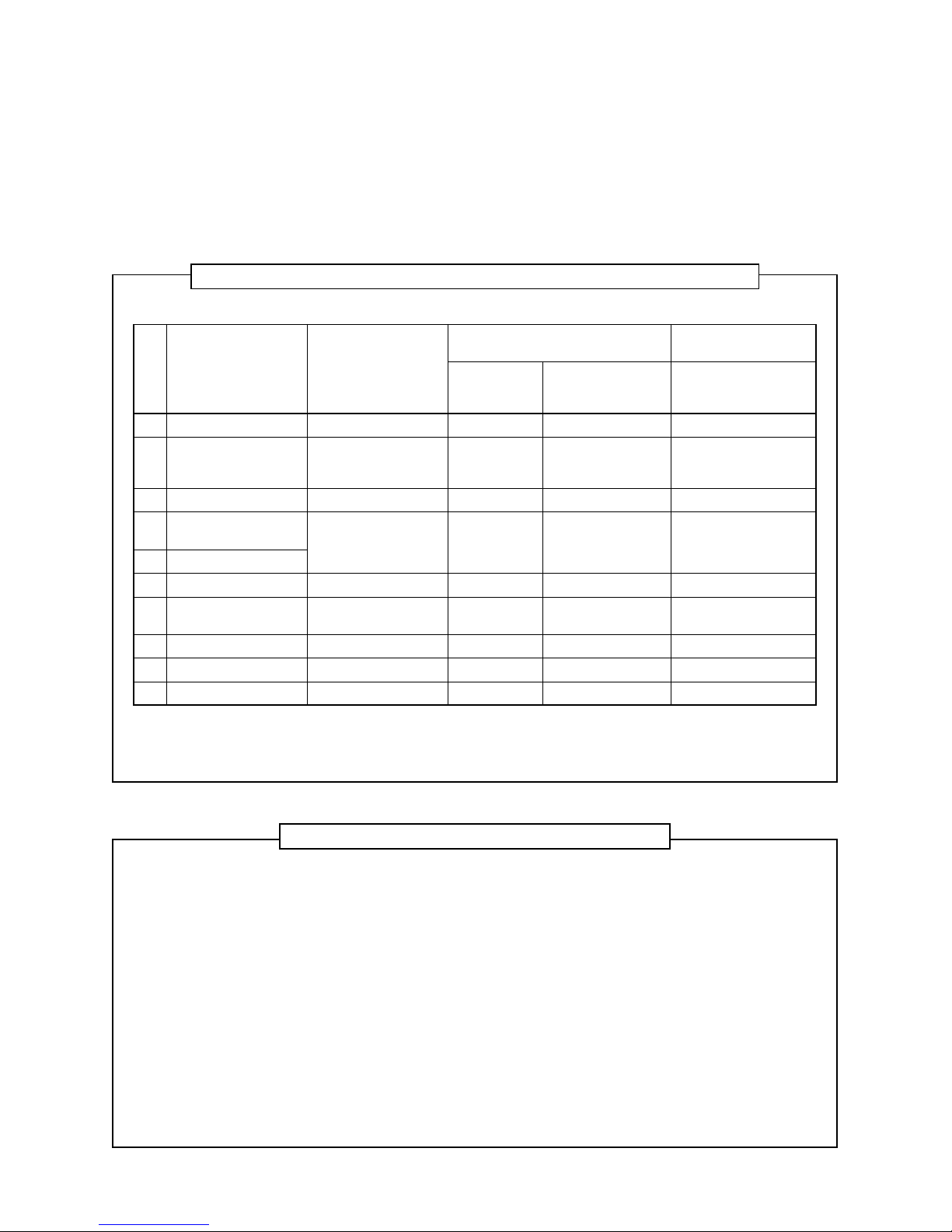
The table below shows the tools exclusive for R410A and their interchangeability.
Tools exclusive for R410A (The following tools for R410A are required.)
Tools whose specifications are changed for R410A and their interchangeability
No.
Q
R
S
T
U
V
W
X
Y
Y
Used tool
Flare tool
Copper pipe gauge for
adjusting projection
margin
Torque wrench
Gauge manifold
Charge hose
Vacuum pump adapter
Electronic balance for
refrigerant charging
Refrigerant cylinder
Leakage detector
Charging cylinder
Usage
Pipe flaring
Flaring by conventional
flare tool
Connection of flare nut
Evacuating, refrigerant
charge, run check, etc.
V acuum evacuating
Refrigerant charge
Refrigerant charge
Gas leakage check
Refrigerant charge
Conventional air
conditioner installation
Whether new equipment
can be used with
conventional refrigerant
Yes
*(Note 1)
No
No
Yes
Yes
No
Yes
No
Whether conventional equipment can
be used
*(Note 1)
*(Note 1)
No
No
No
Yes
No
No
No
(1) Vacuum pump
Use vacuum pump by
attaching vacuum pump adapter.
(2) Torque wrench
(3) Pipe cutter
(4) Reamer
(5) Pipe bender
(6) Lev el vial
(7) Screwdriver (+, –)
(8) Spanner or Monkey wrench
(9) Hole core drill
(10) Hexagon wrench (Opposite side 4mm)
(11) Tape measure
(12) Metal saw
Also prepare the following equipments for other installation method and run check.
(1) Clamp meter
(2) Thermometer
(3) IInsulation resistance tester
(4) Electroscope
Existence of
new equipment
for R410A
Yes
Yes
Yes
Yes
Yes
Yes
Yes
Yes
(Note 2)
R410A
air conditioner installation
(Note 1) When flaring is carried out for R410A using the conventional flare tools, adjustment of projection
margin is necessary. For this adjustment, a copper pipe gauge, etc. are necessary.
(Note 2) Charging cylinder for R410A is being currently developed.
General tools (Conventional tools can be used.)
In addition to the above exclusive tools, the following equipments which serve also for R22 are necessary
as the general tools.
7
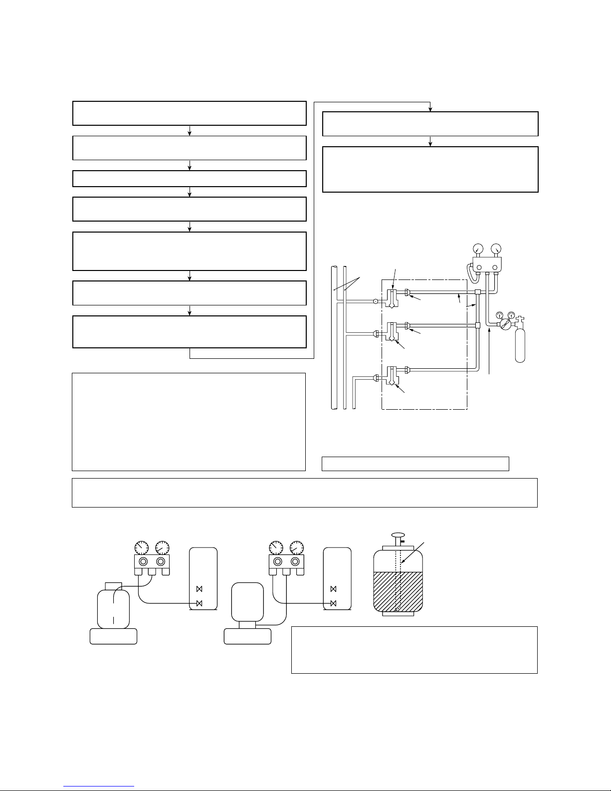
5. Recharge of Refrigerant
When recharge of the refrigerant is required, charge the new refrigerant with the specified amount in the
procedure as described below.
Q
Never charge the refrigerant over the specified amount.
R
Do not charge the additional refrigerant.
If charging refrigerant additionally when refrigerant gas
leaks, the refrigerant composition in the refrigerating
cycle changes resulted in change of air conditioner
characteristics or refrigerant over the specified standard amount is charged and an abnormal high
pressure is applied to the inside of the refrigerating
cycle resulted in cause of breakage or injury .
Q
Set the equipment so that liquid refrigerant can be charged.
R
When using a cylinder with siphon pipe, liquid can be charged without inversing the cylinder.
Gauge manifold
[ Cylinder with siphon ] [ Cylinder without siphon ]
OUTDOOR unit
Gauge manifold
OUTDOOR unit
Electronic
balance
Refrigerant
cylinder
Electronic
balance
Siphon
Refrigerant
cylinder
6. Environment
Use “Vacuum pump method” f or an air purge (Discharge of air in the connecting pipe) in installation time.
• Do not discharge flon gas into the air to protect the earth environment.
• Using the vacuum pump method, clear the remained air (Nitrogen, etc.) in the unit. If the air remains, the
pressure in the refrigerating cycle becomes abnormally high and an injury and others are caused due to burst.
VLV
H
Connected to
indoor unit
Main
pipe
Valve fully closed
(gas side)
Center unit
Low-
pressure gauge
High-
pressure gauge
Gauge
manifold
Brazed
Service
port
Service port
Ø6.4
Copper pipe
Ø6.4
Copper pipe
Fully
tightened
Fully
tightened
Reducing
valve
Nitrogen
gas
Valve fully closed
(liquid side)
Valve fully closed
(balance)
Connected to other
terminal units
(Charge the refrigerant as below.)
Recover the refrigerant and check there is no refrigerant in the
equipment.
Leave it as it is for 1 to 2 minutes and check the indicator of
the compound gauge does not return.
Set the refrigerant cylinder on the electron balance, connect
the charge hose to connecting ports of the cylinder and the
electron gauge, and then charge the liquid refrigerant from the
service port at liquid side. (Shield with the gauge manifold so
that refrigerant does not flow to gas side.)
Connect the charge hose to the packed valve service ports at gas
side, liquid side, and balance side of the outdoor unit.
Open the packed valves of the balance pipe fully at liquid and gas
sides, and then return the valve at gas side a little to the closed side.
Open fully PMV of the outdoor unit.
• Turn on power of the outdoor unit.
• Short CN30 on I/F P.C. board of the outdoor unit.
•
Turn off power of the outdoor unit within 2 minutes after short-circuiting.
Open fully the handle Low of the gauge manifold, and then turn on
the power of vacuum pump for vacuuming.
When the pressure has lowered until indication of the compound
gauge pointed -0.1MPa (-76cmHg), open fully the handle Low and
turn off the power of vacuum pump.
Connect the charge hose to vacuum pump adaptor.
R410A refrigerant is consisted with HFC mixed refrigerant.
Therefore if the refrigerant gas is charged, the composition
of the charged refrigerant changes and characteristics of
the equipment changes.
4mm-hexagonal wrench is required.
8
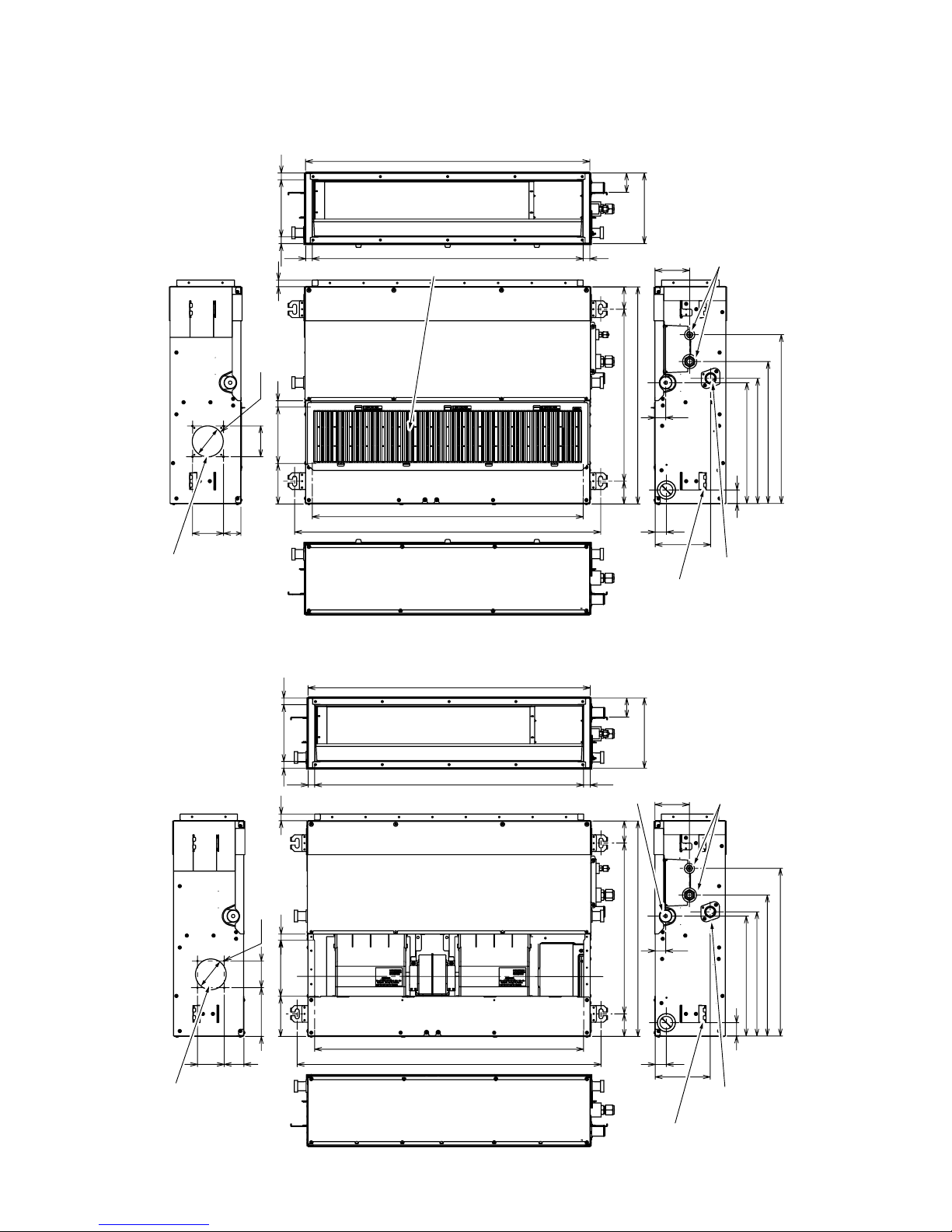
1. CONSTRUCTION VIEWS (EXTERNAL VIEWS)
MMD-AP0071SPH(-K), AP0091SPH(-K), AP0121SPH(-K), AP0151SPH(-K), AP0181SPH(-K)
511
67
67
910
372
359
422
502
103
31
163
33
40
21803 (inside)
57
210
845
168
(inside)
21
21
21
120
805
19
645
168
20
Air filter
Refrigerant piping
Drain-up port
Hung-up plate
Fresh air inlet
(knock-out hole)
80
59
80
4-Ø4
Ø92
372
359
422
502
103
31
163
33
40
146 80
5980
511
67
67
910
21
803 (inside)
57
845
210
168(inside)
21 21
21
4-Ø4
Ø92
168
20
645
805
120
19
Fresh air inlet
(knock-out hole)
Refrigerant
piping
Drain-up port
(SPH model only)
Hang-up plate
Natural drain port
MMD-AP0071SPH-C, AP0091SPH-C, AP0121SPH-C, AP0151SPH-C, AP0181SPH-C,
MMD-AP0071SH-C, AP0091SH-C, AP0121SH-C, AP0151SH-C, AP0181SH-C
9
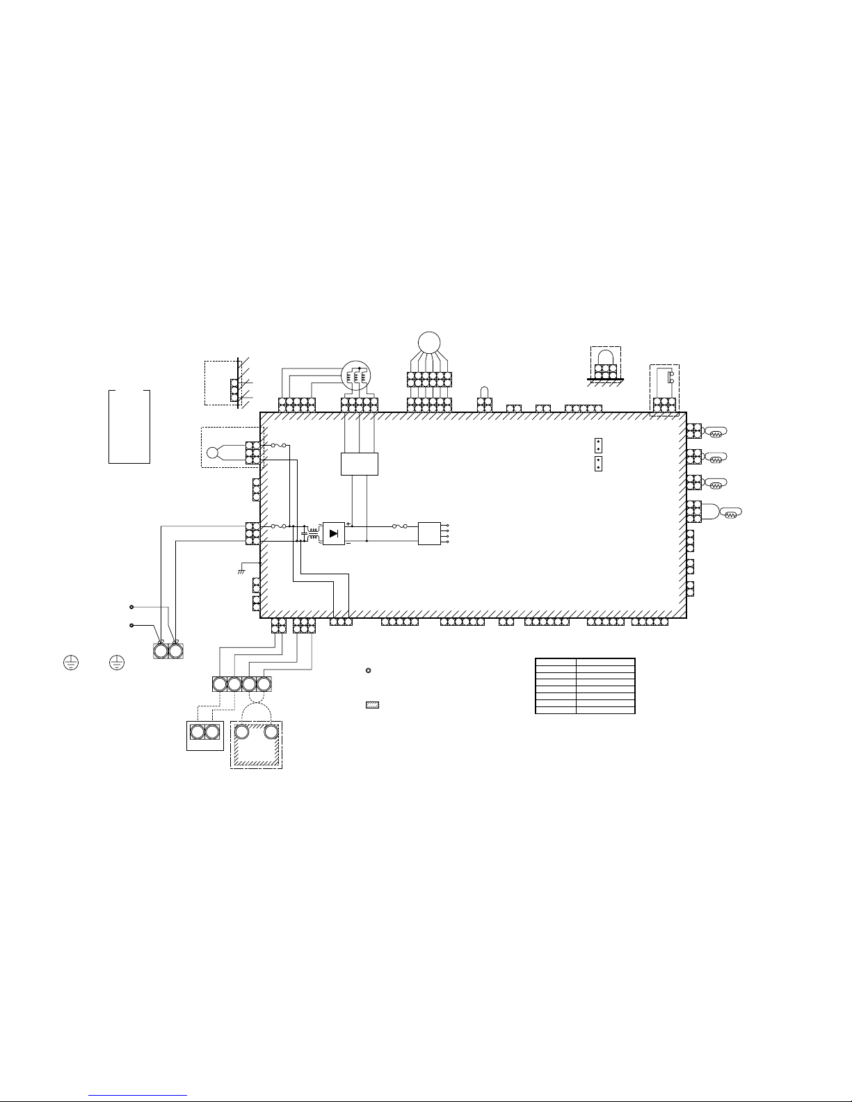
2. WIRING DIAGRAM
MMD-AP0071SPH(SH), AP0091SPH(SH), AP0121SPH(SH), AP0151SPH(SH), AP0181SPH(SH)
Control P.C. board
for undoor unit
MCC-1402
FM
TA
TC1,TC2,TCJ
RY302
PMV
DM
FS
Fan motor
Indoor temp sensor
Temp sensor
Drain control relay
Pulse motor valve
Drain pump motor
Float switch
Symbol
Parts name
5 4 1
5
5
54 3
3
32 1
1
1
31
CN333
(WHI)
CN82
(BLU)
(External static pressure setup)
CN33
(WHI)
CN34
(RED)
Non Drain pump type
("SH" Type)
Drain pump type
("SPH" Type)
CN112
(WHI)
CN334
(WHI)
FM
1 2 3 4 5 6
1
1
1
2
1 2
1 2
CN111
(WHI)
1 2
CN110
(WHI)
1 2 1 2
2
2
3
3
3
4
4
4
5 3
1 2 3
1 3
CN34
(RED)
FS
1 2 3
1 3
4 5
5
5
6
6
6
PMV
131
3
CN104
(YEL)
TA
212
1
CN102
(RED)
TCJ
212
1
CN101
(BLK)
CN100
(BRW)
1
3
CN80
(GRN)
TC2
PNL
EXCT
2
1
CN73
(RED)
2
2
1
CN70
(WHI)
CN20
(BLU)
2
1
2
1
TC1
1 2 3 4 5
CN81
(BLK)
1 2 3 4 5
CN50
(WHI)
CN309
(YEL)
1 2 3 4 5
CN60
(WHI)
CN32
(WHI)
Option
1 2
Fan drive
1 2 3 4 5 6
CN61
(YEL)
CN41
(BLU)
CN40
(BLU)
CN44
(BRW)
1 2 3 4 5 6
11221
1 233
BLU
BLU
BLK
BLK
3
1
3
1
3
1
3
1
313
1
2
1
CN66
(WHI)
WHI
RED
P301
CN67
(BLK)
Motor drive
circuit
CN304
(GRY)
RY302
CN68
(BLU)
CN68
(BLU)
Fuse
T6.3A
250V~
Drain pump type
("SPH" Type)
Non Drain pump type
("SH" Type)
BLK
RED
WHI
2
1
Fuse
T3.15A
250V~
Power
supply
circuit
DC20V
Power supply
220-240V~, 50Hz
220V~, 60Hz
Indoor unit
Earth screw
Closed-end
connector
R(L) S(N)
Flow
Selector unit
Earth screw
Outdoor unit
Wired remote
controller
U1 U2
U1 U2
A B
A B
DM
DC15V
DC12V
DC7V
CN71
CN72
(CHK)
(DISP)
1. indicates the terminal bolock.
Letter at inside indicates the terminal number.
2. A dotted line and broken line indicate the
wiring at side
3. indicate a control P.C. board.
Color
indication
RED : RED
WHI : WHITE
YEL : YELLOW
BLU : BLUE
BLK : BLACK
GRY : GRAY
PNK : PINK
ORN : ORANGE
BRN : BRWN
GRN : GREEN
10
3. PARTS RATING
3-1. P arts Rating
Model MMD-
Fan motor
Pulse motor
Pulse motor valve
Drain pump motor ∗
Float switch ∗
TA sensor
TC1 sensor
TC2 sensor
TCJ sensor
AP0071SPH AP0091SPH AP0121SPH AP0151SPH AP0181SPH
SWF-280-60-1
EDM-MD12TF-3
EDM-B25YGTF EDM-B40YGTF
ADP-1409
FS-0218-102
Lead wire length : 1558mm Vinyl tube
Ø4 size lead wire length : 1200mm Vinyl tube (Blue)
Ø6 size lead wire length : 1200mm Vinyl tube (Black)
Ø6 size lead wire length : 1200mm Vinyl tube (Red)
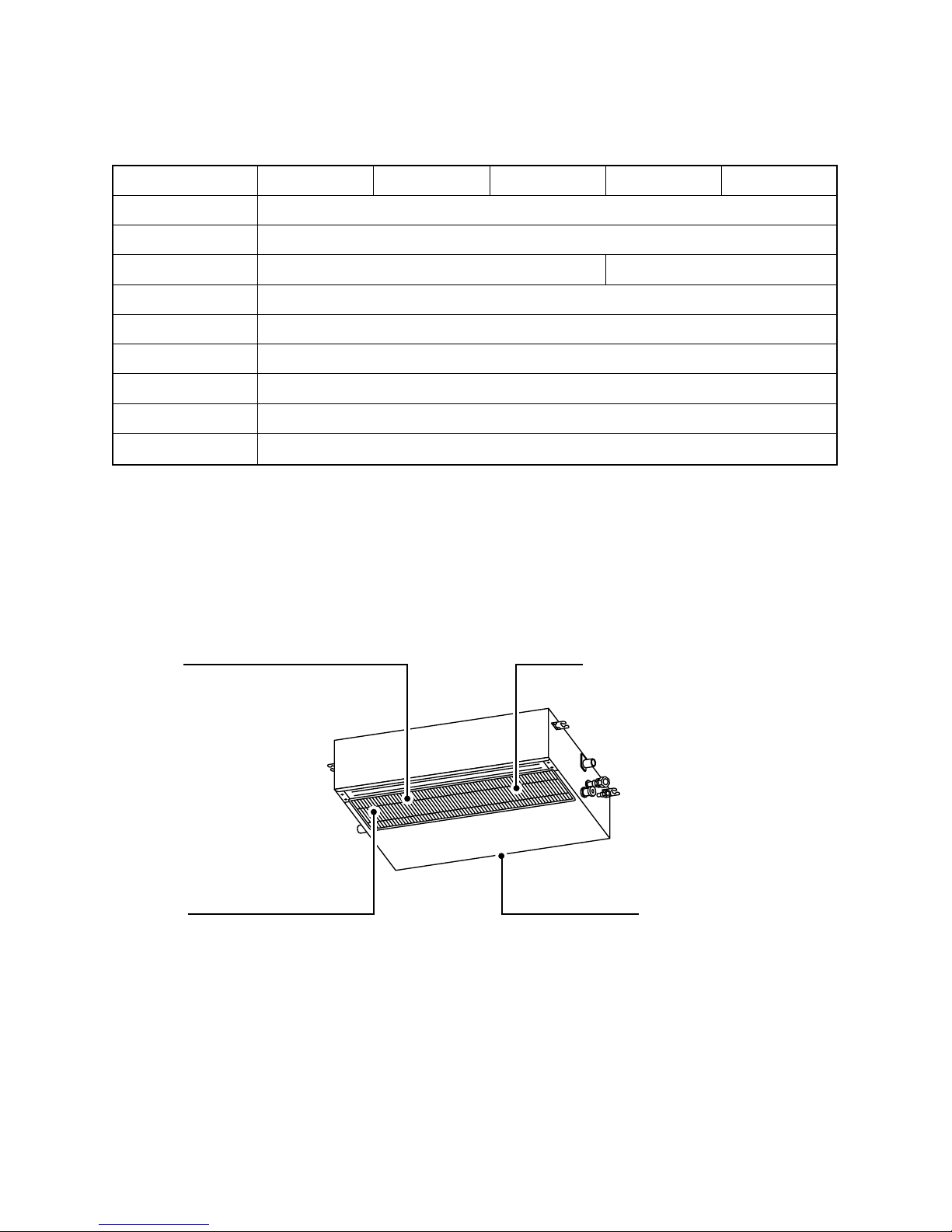
3-2. Name of Each Part
Air inlet
Suction duct is connected.
Earth screw
It is included in the electric parts box.
Air filter
(Air filter is not provided to some models in the series.)
Air outlet
Discharge duct is connected.
∗ “SPH” series only
11
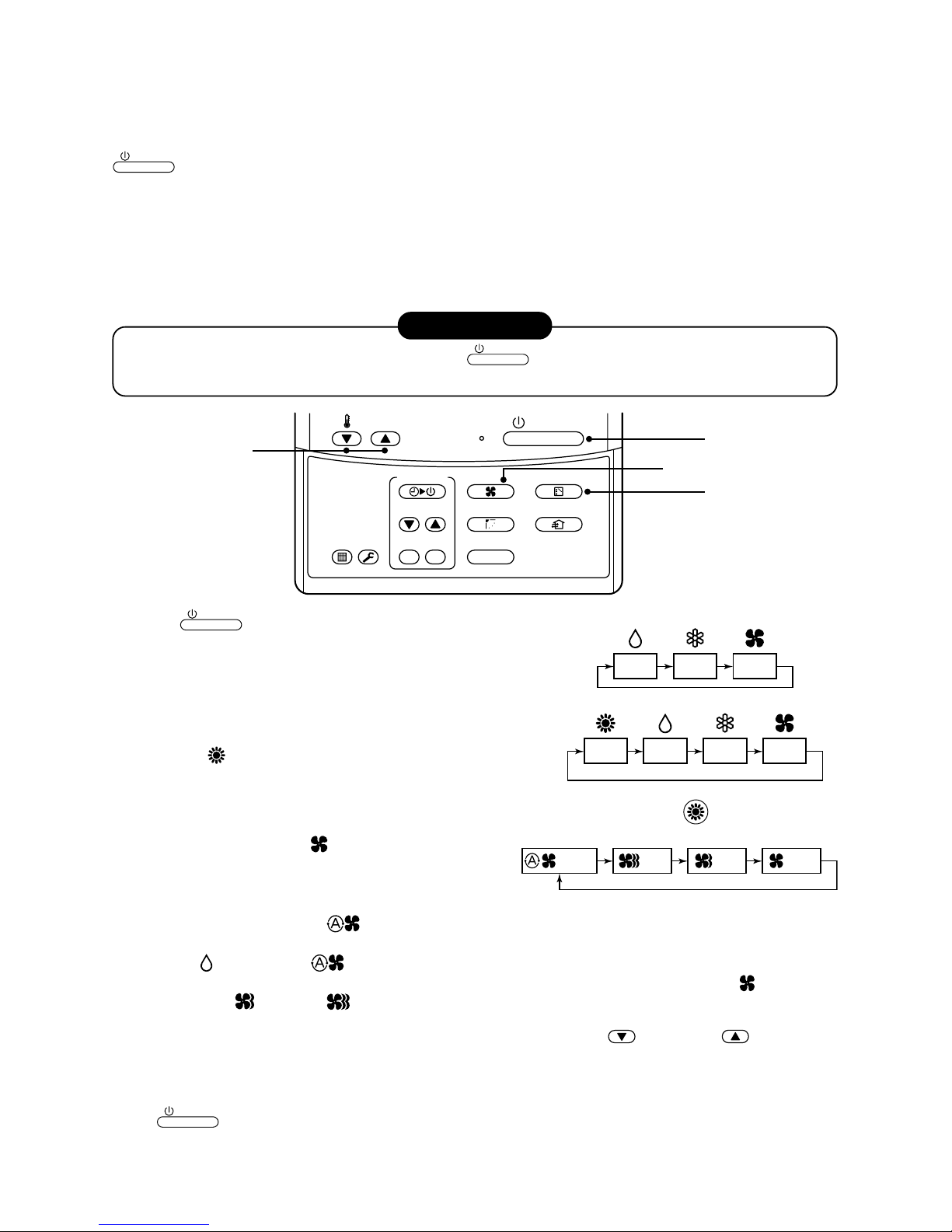
Display
section
Operation
section
ON / OFF
FAN
TEMP.
SWING/FIXTIME
MODE
VENT
UNITSET CL
FILTER
RESET
TEST
TIMER SET
CODE No.
UNIT No.
TEST
SETTING
DATA
SET
R.C. No.
H
2
15
5
78 9
3
1
4
6
10
11
13
16
12
14
17
CODE No.
UNIT No.
TEST
SETTING
DATA
SET
R.C. No.
H
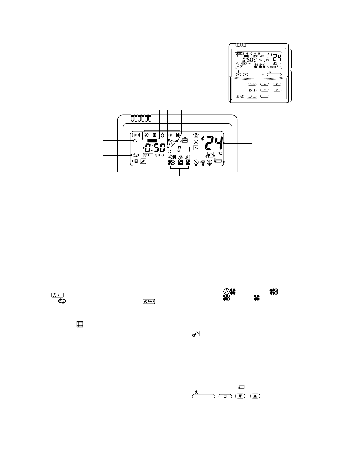
3-3. P arts Name of Remote Controller
Display section
In the display example, all indicators are displayed for the explanation.
In reality only, the selected contents are indicated.
• When turning on the leak breaker at the first time, [SET DATA] flashes
on the display part of the remote controller. While this display is flashing,
the model is being automatically confirmed. Accordingly, wait f or a while
after [SET DATA] display has disappeared, and then use the remote
controller.
1
SET DATA display
Displayed during setup of the timer.
2
Operation mode select display
The selected operation mode is displayed.
3
CHECK display
Displayed while the protective device works or a
trouble occurs.
4
Timer time display
Time of the timer is displayed.
(When a trouble occurs, the check code is displayed.)
5
Timer SETIN setup display
When pushing the Timer SETIN button, the
display of the timer is selected in order of [OFF]
→ [OFF] repeat OFF timer → [ON]
→ No display.
6
Filter display
If “FILTER ” is displayed, clean the air filter.
7
TEST run display
Displayed during a test run.
8
Flap position display
(for 4-Way Air Discharge Cassette Type and
Under Ceiling T ype model only)
Displays flap position.
9
SWING display
Displayed during up/down movement of the flap.
10
Set up temperature display
The selected set up temp. is displayed.
11
Remote controller sensor display
Displayed while the sensor of the remote
controller is used.
12
PRE-HEAT display
Displayed when the heating operation starts or
defrost operation is carried out.
While this indication is displayed, the indoor fan
stops or the mode enters in LOW.
13
Operation ready display
Displayed when cooling or heating operation is
impossible because the outdoor temperature goes
out of the operable range.
14
No function display
Displayed if there is no function even if the button is
pushed.
15
Air volume select display
The selected air volume mode is displayed.
(AUTO)
(HIGH)
(MED.) (LOW)
In the Concealed Duct High Static Pressure type
models, [HIGH] only is displayed for the air speed.
16
Mode select control display
Displayed when pushing “Operation mode select
” button while the operation mode is fixed to
heating or cooling by the system manager of the air
conditioner.
17
Central control display
Displayed when using the remote controller together with the central control remote controller,
etc.
If Remote controller is prohibited at the
centralcontrol side,
flashes when operating
ON / OFF
,
MODE
, / buttons and
the change is not accepted.
(The contents available to be set up on the remote
controller differ according to the central control
mode. For details, refer to Owner’s Manual of the
central control remote controller.)

12
Operation section
Push each button to select a desired operation.
• The details of the operation needs to be set up once, afterward, the air conditioner can be used by pushing
ON / OFF
button only.
7
Operation lamp
Lamp is lit during the operation. Lamp is off
when stopped.
Although it flashes when operating the protection
device or abnormal time.
8
ON / OFF
button
When the button is pushed, the operation starts,
and it stops by pushing the button again.
When the operation has stopped, the operation
lamp and all the displays disappear.
9
Operation select button
Selects desired operation mode.
10
Set up temperature button
Adjusts the room temperature.
Set the desired set temperature by pushing
or .
OPTION :
Remote controller sensor
UUsually the TEMP. sensor of the indoor unit senses
the temperature. The temperature on the surrounding of the remote controller can also be sensed.
For details, contact the dealer from which you have
purchased the air conditioner.
• In case that one remote controller controls the
multiple indoor units, the setup operation is
unavailab le in g roup control.
1
7
3
5
2
8
9
6
4
10
ON / OFF
FAN
TEMP.
SWING/FIXTIME
MODE
VENT
UNITSET CL
FIL TER
RESET
TEST
TIMER SET
1
Air volume select button
Selects the desired air volume mode.
The Concealed Duct High Static Pressure type
models cannot be operated.
2
Timer set button
TIMER SET button is used when the timer is set
up.
3
Check button
The CHECK button is used for the check operation. During normal operation, do not use this
button.
4
Fan button
FAN button is used when a fan which is sold on
the market or etc. is connected.
• If is displayed on the remote controller
when pushing the FAN button, a fan is not
connected.
5
Filter reset button
Resets (Erases) “FILTER ” display.
6
Wind direction and Swing
UNIT
:
If the multiple indoor units are operated by only
one remote controller, select the units when the
air direction is adjusted.
SWING/FIX
:
Set up the auto swing and angle of the flap .
• This function is not provided to Concealed
Duct Standard Type, High Static Pressure
Type, Floor standing Cabinet Type, Floor
Standing Concealed Type, or Slim Duct Type.
13
3-4. Correct Usage
When you use the air conditioner for the first time or when you change the SET DATA value, follow the procedure below. From the next time, the operation displayed on the remote controller will start by pushing the
ON / OFF
button only.
Preparation
Turn on the main power switch and/or the leakage breaker.
• When the power supply is turned on, a partition line is display ed on the display part of the remote controller.
* After the power supply is turned on, the remote controller does not accept an operation for approx. 1 minute,
but it is not a failure.
REQUIREMENT
• While using the air conditioner, operate it only with
ON / OFF
button without turning off the main power
switch and the leak breaker.
1
Push
ON / OFF
button.
The operation lamp goes on, and the operation starts.
2
Select an operation mode with the “MODE” button.
One push of the button, and the display
changes in the order shown on the right.
• In HEAT mode, if the room temperature reaches to
the set temperature, the outdoor unit stops and the air
flow becomes LOW and the air volume decreases .
• In the defrost mode, the fan stops so that cool air is not discharged and PRE-DEF is display ed.
3
Select air volume with “ ” button.
One push of the button, and the display
changes in the order shown on the right.
• When air volume is “AUTO ”, air volume differs according to the temperature difference between set
temp. and room temp.
• In DRY mode, “AUTO ” is displayed and the air volume is LOW.
• In heating operation, if the room temperature is not heated sufficiently with VOLUME “LOW ” operation,
select “MED. ” or “HIGH ” operation.
4
Determine the set up temperature by pushing the “TEMP. TEMP. ” or “TEMP. ” button.
Stop
Push
ON / OFF
button.
The operation lamp goes off, and the operation stops.
1
3
2
4
ON / OFF
FAN
TEMP.
SWING/FIXTIME
MODE
VENT
UNITSET CL
FIL TER
RESET
TEST
TIMER SET
HEAT DRY COOL FAN
Heat-pump model
DRY COOL FAN
Cooling only model
(Dehumidity)
LOW MED. HIGH
AUTO
14
1
2
3
ON / OFF
FAN
TEMP.
SWING/FIXTIME
MODE
VENT
UNITSET CL
FIL TER
RESET
TEST
TIMER SET
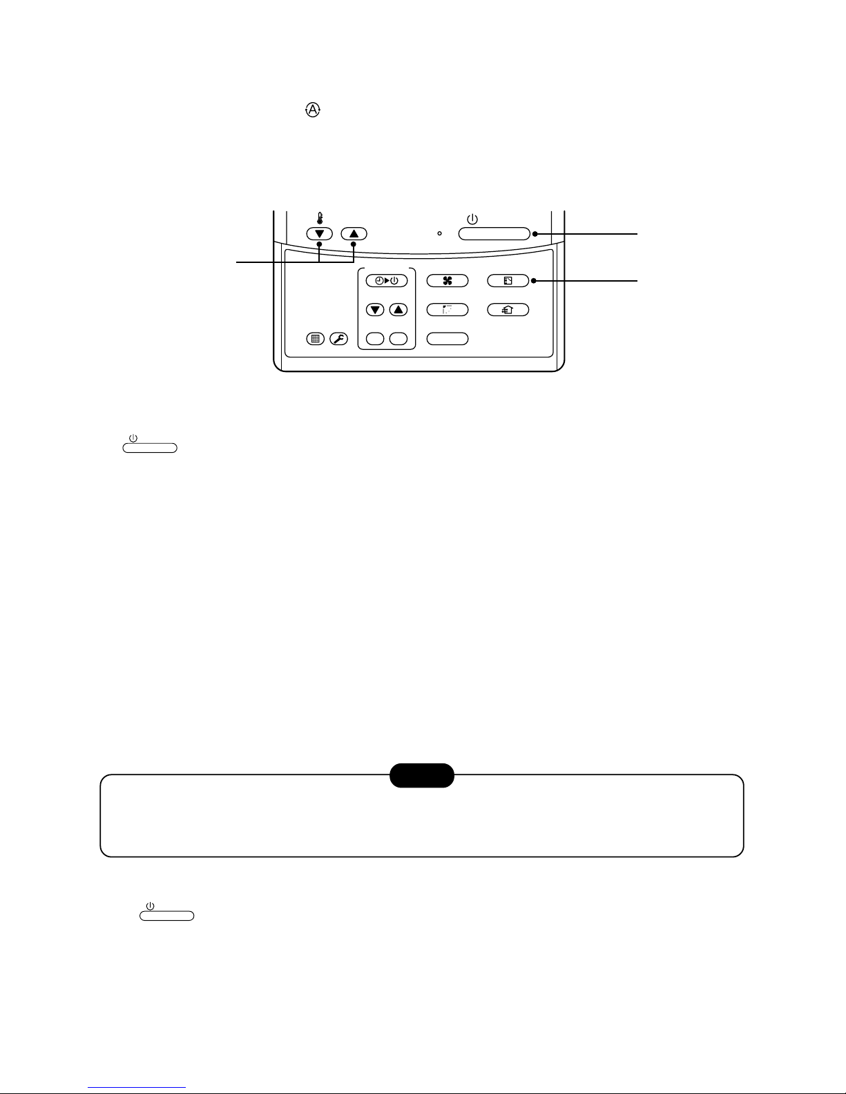
3-5. A utomatic Operation (Super Heat Recovery Type Only)
When you set the air conditioner in mode or switch over from AUTO operation because of some settings
change, it will automatically select either cooling, heating, or fan only operation depending on the indoor temperature.
Start
1
ON / OFF
button
Push this button to start the air conditioner.
2
Mode select button (MODE)
Select Auto.
3
Temperature button
Set the desired temperature.
• In case of cooling, start the operation after approx. 1 minute.
• In case of heating, the operation mode is selected in accordance with the room temperature and operation
starts after approximately 3 to 5 minutes.
• When you select the Auto mode, it is unnecessary to set the fan speed.
The F AN speed display will show AUTO and the fan speed will be automatically controlled.
• After the heating operation has stopped, F AN operation may continue for approx. 30 seconds.
• When the room temperature reaches the set temperature and the outdoor unit stops, the super low wind is
discharged and the air volume decreases excessiv ely.
During defrost operation, the fan stops so that cool air is not discharged and “HEAT READY” is displayed.
• If the Auto mode is uncomfortable, you can select the desired conditions manually.
NOTE
When restarting the operation after stop
• When restarting the operation immediately after stop, the air conditioner does not operate for approx. 3
minutes to protect the machine.
Stop
Push
ON / OFF
button.
Push this button again to stop the air conditioner.
15
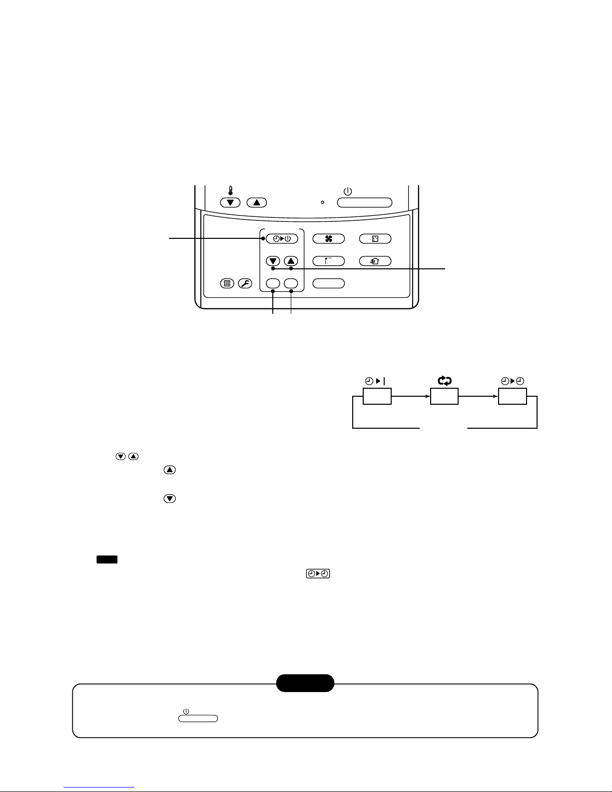
3-6. TIMER Operation
A type of timer operation can be selected from the following three types .
OFF timer : The operation stops when the time of timer has reached the set time.
Repeat OFF timer : Every time, the operation stops after the set time has passed.
ON timer : The operation starts when the time of timer has reached the set time.
Timer operation
1
Push TIMER SET button.
• The timer display (type) changes for e very
push of the button.
• SET TIME and timer time displays flash.
2
Push
TIME
to select “SET TIME”.
For every push of button, the set time increases in the unit of 0.5 hr (30 minutes).
The maximum set time is 72.0 hr.
For every push of button, the set time decreases in the unit of 0.5 hr (30 minutes).
The minimum set time is 0.5 hr.
3
Push SET button.
•
SETTING
display disappears and timer time display goes on.
(When ON timer is activated, timer time, ON timer are displayed and other displays disappear.)
Cancel of timer operation
4
Push CL button.
• TIMER display disappears.
NOTICE
• When the operation stops after the timer reached the preset time, the Repeat OFF timer resumes the
operation by pushing
ON / OFF
button and stops the operation after the time of the timer has reached the
set time.
4
3
2
1
ON / OFF
FAN
TEMP.
SWING/FIXTIME
MODE
VENT
UNITSET CL
FIL TER
RESET
TEST
TIMER SET
OFF
(OFF timer) (Repeat OFF timer)
No display
(ON timer)
OFF ON
16
3-7. Information
Confirmation before operation
• Turn on the power switch 12 hours before starting
the operation.
• Make sure whether earth wire is connected.
• Make sure the air filter is connected to the indoor
unit.
Heating capacity
• A heat pump system which absorbs heat from
outside of the room and then discharges heat into
the room is adopted for heating. If the outside
temperature falls, the heating capacity decreases.
• When the outside temperature is too low, it is
recommended to use this air conditioner together
with other heating equipment.
Defrost during heating operation
• In heating operation, if there is frost on the outdoor
unit, the operation changes automatically to the
defrost operation (Approx. 2 to 10 minutes) to
increase the heating efficiency.
• During defrost operation, the fan of the indoor unit
stops.
3-minutes protection
• When restarting the operation just after the
operation has been stopped or the main power
switch has turned on, the outdoor unit does not
work for approx. 3 minutes in order to protect the
air conditioner.
Power failure
• If a power failure occurred during operation, all
operations stop.
• When the power is returned after a power failure,
the operation lamp notifies the power-ON by
flashing operation lamp on the remote controller.
• When restarting the operation, push
ON / OFF
button again.
Fan rotation in stopped unit
• In heating operation even in the stopped indoor
unit, the fan rotates once for several minutes per
approx. an hour when the other indoor unit is
operating to protect the air conditioner.
Protective device (High pressure switch)
This device stops automatically an operation when
excessive force is applied on the air conditioner.
If the protective device works, the operation stops
and the operation lamp flashes.
When the protective device works, the indication
TEST
and the check code are displayed on the display
section of the remote controller. In the following
cases, the protective device may work.
In cooling operation
• The suction port or discharge port of the outdoor
unit is closed.
• A strong wind continuously blows to the discharge
port of the outdoor unit.
In heating operation
• Dust or waste adheres excessively to air filter of
the indoor unit.
• The discharge port of the indoor unit is closed.
If the protective device works, turn off the main
power switch, solve the cause, and then start the
operation again.
Cooling/Heating operation of Super
Modular Multi system air conditioner
• Although each indoor unit can be individually
controlled in the Super Modular Multi system air
conditioner, the cooling oper ation and the heating
operation cannot be simultaneously performed in
the multiple indoor units which are connected to
an outdoor unit.
• If the cooling operation and the heating operation
are simultaneously performed, the indoor unit
which ex ecutes cooling operation stops, and on
the operation section lights up. On the other hand,
the indoor unit which executes heating operation
continues running. In a case that the manager of
the air conditioner has fixed the operation to
cooling or heating, an operation other than that set
up is unavailab le. If an operation other than that
set up is executed, on the operation section
lights up and the operation stops.
Characteristics of heating operation
• The wind is not out just after starting an operation.
The hot wind starts to blow 3 to 5 minutes after
(Time differs according to indoor/outdoor temperature.) the indoor heat exchanger has warmed up.
• During operation, the outdoor unit may stop if the
outside temperature rises.
17
3-8. Air Conditioner Operations and P erformance
3 minutes protection function
3-minutes protection function prev ents the air conditioner from starting f or initial 3 minutes after the main power
switch/circuit breaker is turned on for re-starting the air conditioner .
Power failure
Po wer failure during operation will stop the unit completely.
• To restart the operation, push the START/STOP b utton on the remote controller.
• Lightning or a wireless car telephone operating nearby may cause the unit to malfunction. Turn off the main
power switch or circuit breaker and then turn them on again. Push the START/STOP button on the remote
controller to restart.
Heating characteristics
Preheating operation
The air conditioner will not deliver warm air immediately after it is turned on. Warm air will start to flow out after
approximately 5 minutes when the indoor heat exchanger w armed up.
Warm air control (In heating operation)
When the room temperature reaches the set temperature, the fan speed is automatically reduced to prevent to
blow cold draft. At this time, the outdoor unit will stop.
Defrosting operation
If the outdoor unit is frosted during the heating operation, defrosting starts automatically (for approximately
2 to 10 minutes) to maintain the heating capacity.
• The fans in both indoor and outdoor units will stop during the defrosting operation.
• During the defrosting operation, the defrosted water will be drained from the bottom plate of the outdoor unit.
Heating capacity
In the heating operation, the heat is absorbed from the outside and brought into the room. This way of heating
is called heat pump system. When the outside temperature is too low, it is recommended to use another heating
apparatus in combination with the air conditioner .
Attention to snowfall and freeze on the outdoor unit
• In snowy areas, the air inlet and air outlet of the outdoor unit are often covered with snow or froz en up.
If snow or freeze on the outdoor unit is left as it is, it may cause machine failure or poor warming.
• In cold areas, pay attention to the drain hose so that it perfectly drains w ater without water remaining inside for
freeze prevention. If water freezes in the drain hose or inside the outdoor unit, it may cause machine failure or
poor warming.
Air conditioner operating conditions
For proper performance, operate the air conditioner under the following temperature conditions:
If air conditioner is used outside of the above conditions, safety protection may work.
Cooling operation
Dry operation
Outdoor temperature : –5°C to 43°C (Dry valve temp.)
Room temperature : 21°C to 32°C (Dry valve temp.), 15°C to 24°C (Wet valve temp.)
CAUTION
Room relative humidity – less than 80 %. If the air conditioner operates
in excess of this figure, the surface of the air conditioner may cause dewing.
Outdoor temperature : 15°C to 21°C (Dry valve temp.), –15°C to 15.5°C (Wet valve temp.)
Room temperature : 15°C to 28°C (Dry valve temp.)
18
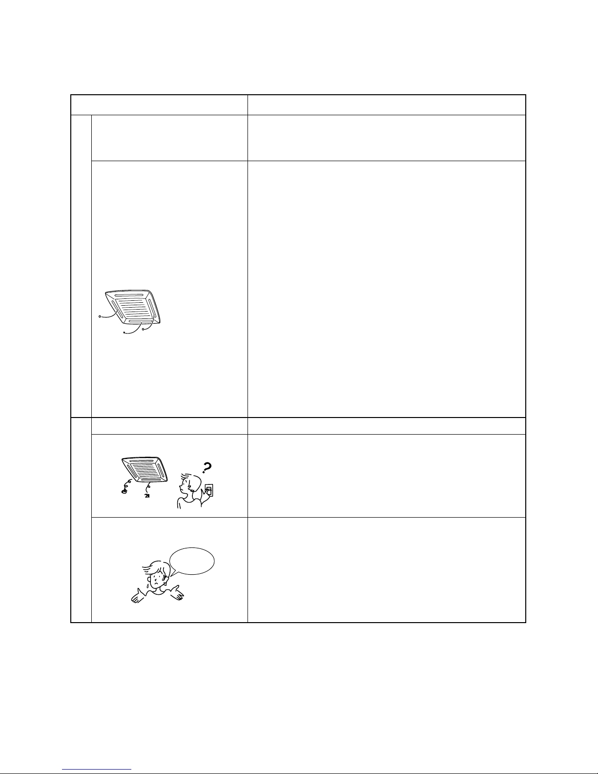
3-9. When the Following Symptoms are Found
Check the points described below before asking repair servicing.
Symptom
Outdoor unit • White misty cold air
or water is out.
• Sometimes, noise
“Pushu !” is heard.
Indoor unit •“Swish” sound is
heard sometimes.
• Slight “Pishi!” sound
is heard.
• Discharge air smells.
• The operation lamp
flashes
•“STANDBY”
indication is lit.
• Sound or cool air is
output from the
stand by indoor unit.
• When power of the
air conditioner is
turned on, “Ticktock”
sound is heard.
Operates or stops automatically.
Does not operate.
Air is not cooled or warmed sufficiently.
Cause
• Fan of the outdoor unit stops automatically and performs defrost
operation.
• Solenoid valve works when defrost operation starts or finishes.
• When the operation has started, dur ing the operation, or immediately
after the operation has stopped, a sound such as water flows may be
heard, and the operation sound may become larger for 2 or 3 minutes
immediately after the operation has started. They are flowing sound of
refrigerant or draining sound of dehumidifier.
• This is sound generated when heat exchanger, etc. expand and
contract slightly due to change of temperature.
• Various smell such as one of wall, carpet, clothes, cigarette, or
cosmetics adhere to the air conditioner.
• Flashes when power is turned on again after power failure, or when
power switch is turned on.
• When cooling operation cannot be performed because another indoor
unit performs heating operation.
• When the manager of the air conditioner has fixed the operation to
COOL or HEAT, and an operation contrary to the setup operation is
performed.
• When fan operation stopped to prevent discharge of hot air.
• Since refrigerant is flowed temporarily to prevent stay of oil or
refrigerant in the stand by indoor unit, sound of flowing refrigerant,
“Kyururu” or “Shaa” may be heard or white steam when other indoor
unit operates in HEAT mode, and cold air in COOL mode may be
blow-out.
• Sound is generated when the expansion valve operates when power
has been turned on.
• Is the timer “ON” or “OFF”?
• Is it a power failure?
• Is the power switch turned off?
• Is the power fuse or breaker blown?
• Has the protective device operated? (The operation lamp goes on.)
• Is the timer “ON”? (The operation lamp goes on.)
• Are COOL and HEAT selected simultaneously? (“STANDBY” indication is lit on the display column of the remote controller.)
• Is the suction port or discharge port of the outdoor unit obstructed?
• Are any door or window open?
• Is the air filter clogged with dust?
• Is discharge louver of the indoor unit set at appropriate position?
• Is air selection set to “LOW” “MED”, and is the operation mode set to
“FAN”?
• Is the setup temp. the appropriate temperature?
• Are COOL and HEAT selected simultaneously? (“STANDBY” indication is lit on the display column of the remote controller.)
It is not a failure.
Check again.
When the following symptoms are found, stop the operation immediately, turn off the power switch, and contact
the dealer which you have purchased the air conditioner.
• Activation of switch is unstable.
• Fuse or breaker is blown periodically.
• Foreign matters or water entered by mistake.
• When if activation cause of the protective device has been removed, the operation is not performed.
• Other unusual status occurred.
Silent
It’s strange.
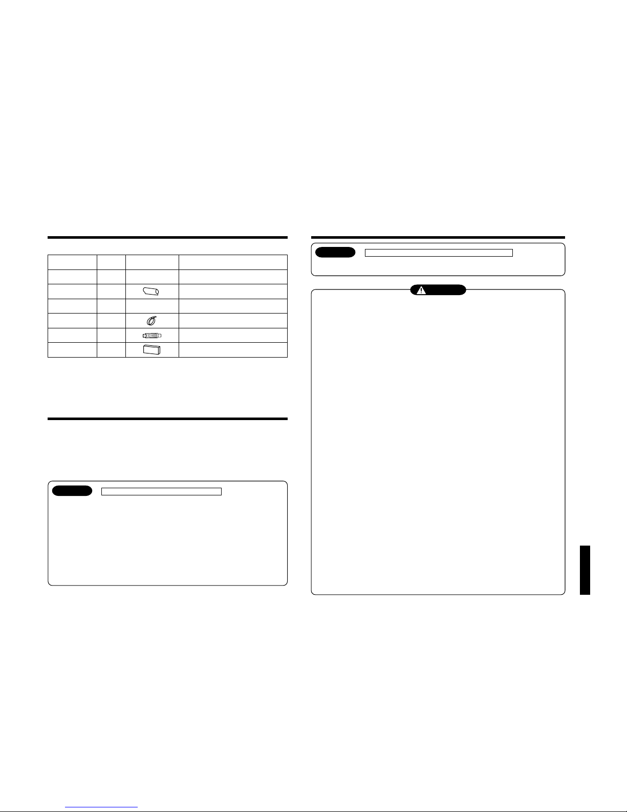
19
“SPH” series
Shape
This manual
M10 × Ø34
——
Part name
Installation Manual
Insulating pipe
Washer
Hose band
Flexible hose
Heat insulator
Q’ty
1
2
8
1
1
1
Usage
(Be sure to hand over to customers)
For insulating pipe connecting section
For hanging down the unit
For connecting drain pipe
For adjustment of drain pipe centering
For insulating drain connecting section
1
PRECAUTIONS FOR SAFETY
• Ensure that all Local, National and International regulations are satisfied.
• Read this “PRECAUTIONS FOR SAFETY” carefully before Installation.
• The precautions described below include the important items regarding safety. Observe them without fail.
• After the installation work, perform a trial operation to check for any problem.
Follow the Owner’s Manual to explain how to use and maintain the unit to the customer.
• Turn off the main power supply switch (or breaker) before the unit maintenance.
• Ask the customer to keep the Installation Manual together with the Owner’s Manual.
CAUTION New Refrigerant Air Conditioner Installation
• THIS AIR CONDITIONER ADOPTS THE NEW HFC REFRIGERANT (R410A) WHICH DOES NOT
DESTROY OZONE LAYER.
The characteristics of R410A refrigerant are ; easy to absorb water, oxidizing membrane or oil, and its
pressure is approx. 1.6 times higher than that of refrigerant R22. Accompanied with the new refrigerant,
refrigerating oil has also been changed. Therefore, during installation work, be sure that water, dust,
former refrigerant, or refrigerating oil does not enter the refrigerating cycle.
To prevent charging an incorrect refrigerant and refrigerating oil, the sizes of connecting sections of
charging port of the main unit and installation tools are charged from those for the conventional
refrigerant.
Accordingly the exclusive tools are required for the new refrigerant (R410A).
For connecting pipes, use new and clean piping designed for R410A, and please care so that water or
dust does not enter. Moreover, do not use the existing piping because there are problems with pressureresistance force and impurity in it.
CAUTION To Disconnect the Appliance from Main Power Supply.
This appliance must be connected to the main power supply by means of a switch with a contact separation of
at least 3 mm.
WARNING
• Ask an authorized dealer or qualified installation professional to install/maintain the air
conditioner.
Inappropriate installation may result in water leakage, electric shock or fire.
• Turn off the main power supply switch or breaker before attempting any electrical work.
Make sure all power switches are off. Failure to do so may cause electric shock.
• Connect the connecting wire correctly.
If the connecting wire is connected in a wrong way, electric parts may be damaged.
• When moving the air conditioner for the installation into another place, be very careful not to
enter any gaseous matter other than the specified refrigerant into the refrigeration cycle.
If air or any other gas is mixed in the refrigerant, the gas pressure in the refrigeration cycle becomes
abnormally high and it as a result causes pipe burst and injuries on persons.
• Do not modify this unit by removing any of the safety guards or by by-passing any of the safety
interlock switches.
• Exposure of unit to water or other moisture before installation may cause a short-circuit of
electrical parts.
Do not store it in a wet basement or expose to rain or water.
• After unpacking the unit, examine it carefully if there are possible damage.
• Do not install in a place that might increase the vibration of the unit.
• To avoid personal injury (with sharp edges), be careful when handling parts.
• Perform installation work properly according to the Installation Manual.
Inappropriate installation may result in water leakage, electric shock or fire.
• When the air conditioner is installed in a small room, provide appropriate measures to ensure that
the concentration of refrigerant leakage occur in the room does not exceed the critical level.
• Install the air conditioner securely in a location where the base can sustain the weight
adequately.
• Perform the specified installation work to guard against an earthquake.
If the air conditioner is not installed appropriately, accidents may occur due to the falling unit.
• If refrigerant gas has leaked during the installation work, ventilate the room immediately.
If the leaked refrigerant gas comes in contact with fire, noxious gas may generate.
• After the installation work, confirm that refrigerant gas does not leak.
If refrigerant gas leaks into the room and flows near a fire source, such as a cooking range, noxious gas might
generate.
• Electrical work must be performed by a qualified electrician in accordance with the Installation
Manual. Make sure the air conditioner uses an exclusive power supply.
An insufficient power supply capacity or inappropriate installation may cause fire.
• Use the specified wires for wiring connect the terminals securely fix. To prevent external forces
applied to the terminals from affecting the terminals.
• Conform to the regulations of the local electric company when wiring the power supply.
Inappropriate grounding may cause electric shock.
• Do not install the air conditioner in a location subject to a risk of exposure to a combustible gas.
If a combustible gas leaks, and stays around the unit, a fire may occur.
Accessory parts
H Accessory parts
3-10. Installation Manual
20
“SPH” series
2
INSTALLATION OF NEW REFRIGERANT AIR CONDITIONER
This air conditioner adopts the new HFC refrigerant (R410A) which does not deplete the ozone layer.
• R410A refrigerant is apt to be affected by impurity such as water, oxidizing membrane, or oils because the
pressure of R410A refrigerant is higher than that of the former refrigerant by approx. 1.6 times. Accompanied with
adoption of the new refrigerant, refrigerating oil has been also changed. Therefore pay attention so that water,
dust, former refrigerant, or refrigerating oil does not enter into the refrigerating cycle of the new refrigerant air
conditioner during installation work.
• To prevent from mixing of refrigerant or refrigerating oil, the size of charge port of the main unit or connecting
section of installation tool differs from that of the air conditioner for the former refrigerant. Accordingly the
exclusive tools are required for the new refrigerant (R410A) as shown below.
• For connecting pipes, use the new and clean piping materials so that water or dust does not enter.
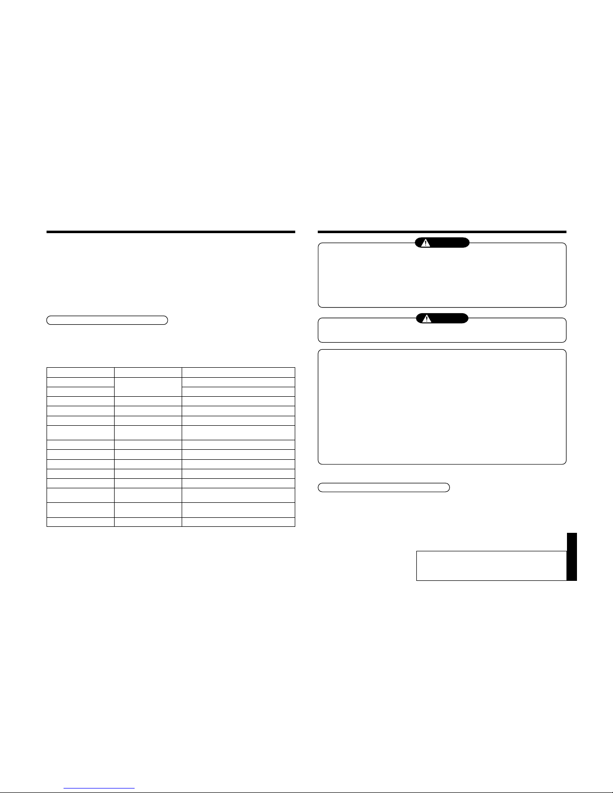
Required tools and cautions on handling
It is necessary to prepare the tools and parts as described below for the installation work.
The tools and parts which will be newly prepared in the following items should be restricted to the exclusive use.
Explanation of symbols
l
: Newly prepared (It is necessary to use it properly exclusive to R410A separated from those for R22 or R407C.)
¡: Former tool is available.
Used tools
Gauge manifold
Charging hose
Charging cylinder
Gas leak detector
Vacuum pump
Vacuum pump with counter-
flow preventive adapter
Flare tool
Bender
Refrigerant recovery device
Torque wrench
Pipe cutter
Refrigerant cylinder
Welding machine/
Nitrogen gas cylinder
Refrigerant charging balance
Usage
Vacuuming or charging of
refrigerant and operation check
Charges refrigerant
Checks gas leak
Vacuum drying
Vacuum drying
Flare processing of pipes
Bending processing of pipes
Recovers refrigerant
Tightens flare nut
Cuts pipes
Charges refrigerant
Welding of pipes
Charges refrigerant
Proper use of tools/parts
l
Newly prepared, Exclusive to R410A
l
Newly prepared, Exclusive to R410A
Unusable (Use the Refrigerant charging balance.)
l
Newly prepared
Usable if a counter-flow preventive adapter is attached
¡
: R22 (Existing article)
¡
: Usable by adjusting size
¡
: R22 (Existing article)
l
Exclusive to R410A
l
Ø12.7mm, Exclusive for Ø15.9mm
¡
: R22 (Existing article)
l
Exclusive to R410A
ID : Refrigerant name entered
¡
: R22 (Existing article)
¡
: R22 (Existing article)
3
SELECTION OF INSTALLATION PLACE
WARNING
• Install the air conditioner where there is sufficient strength to weight of the unit.
If strength is insufficient, the unit may fall down resulting in human injury.
• Perform a specified installation work to guard against an earth quake.
An incomplete installation can cause accidents by the units failing and dropping.
• Install the air conditioner at a height 2.5m or more from the floor.
If you insert your hands or others directly into the unit while the air conditioner operates, it is dangerous
because you may contact with revolving fan or active electricity.
CAUTION
• Do not install the air conditioner in a location subject to a risk of exposure to combustible gas.
Should the combustible gas leak and collect near the unit, fire may occur.
Upon approval of the customer, install the air conditioner in a place that satisfies the
following conditions.
• Place where the unit can be installed horizontally.
• Place where a sufficient servicing space can be ensured for safe maintenance and check.
• Place where drained water will not cause any problem.
Avoid installing in the following places.
• Place exposed to air with high salt content (seaside area), or place exposed to large quantities of sulfide gas
(hot spring). (Should the unit be used in these places, special protective measures are needed.)
• Place exposed to oil, vapor, oil smoke or corrosive gas.
• Place where organic solvent is used nearby.
• Place close to a machine generating high frequency.
• Place near door or window where may come to contact with the fresh air of high humidity.
(Dewing may be caused.)
• Place where special spray is frequently used.
• Place with poor ventilation.
Installation under high-humidity atmosphere
In some cases including the rainy season, especially inside of the ceiling may become high-humidity atmosphere
(dew-point temperature: 23°C or higher).
1. Installation to inside of the ceiling with tiles on the roof
2. Installation to inside of the ceiling with slated roof
3. Installation to a place where inside of the ceiling is used for pathway to intake the fresh air
• In the above cases, additionally attach the heat insulator to all positions of the air conditioner, which come to
contact with the high-humidity atmosphere. In this case, arrange the side plate (Check port) so that it is easily
removed.
• Apply also a sufficient heat
insulation to the duct and
connecting part of the duct.
[Reference] Dewing test conditions
Indoor side: 27°C dry bulb temperature
24°C wet bulb temperature
Air volume: Low air volume, operation time 4 hours
21
“SPH” series
Air outlet
100 or more
250
or more
5 or more
210
235 or more
50 or more
Air inlet
5 or more
210
235
or more
2500 or more
Ceiling
Floor surface
2500 or more
Floor surface
Air inlet
5 or more
210
235
or more
300 or more
Ceiling
(Unit : mm)
Ceiling
Air outlet
50
50
945
645
645
745
Service door (Ceiling opening)
645
945
Service door (Ceiling opening)
Air filter
745
945
3
SELECTION OF INSTALLATION PLACE
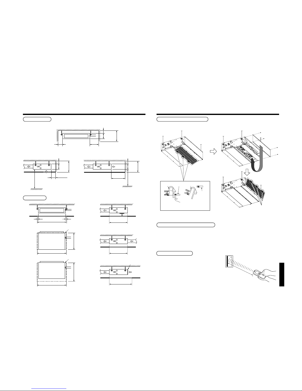
Installation space
Reserve space required for maintenance the indoor unit and service work.
<Under air inlet> <Back air inlet>
Service space
Remove the filter from the main unit while
pushing down on the tabs.
Force
Air filter
Main unit
Remove the cover plate
and then fix it to the
bottom surface.
Main unit
(after remover)
Air filter
Do surely hooking
to the main unit.
8m or less
Notification of filter cleaning term setup
The lighting term setup of the filter sign (Notification of filter cleaning) of the remote controller can be changed
according to the condition of installation.
For setup method, refer to “Change of lighting term of filter sign” and “To secure better effect of heating” in the
Applicable controls of this Manual.
In case of wireless type
The sensor of indoor unit with wireless remote
controller can receive a signal 8m or less.
Based upon it, determine a place where the remote
controller is operated and the installation place of the
indoor unit.
• To prevent a malfunction, select a place where is not
influenced by a florescent light or direct sunlight.
• Two or more (Up to 6 units) indoor units with
wireless remote controller can be installed in the
same room.
Arranging the to back air inlet type
<Back air inlet>
22
“SPH” series
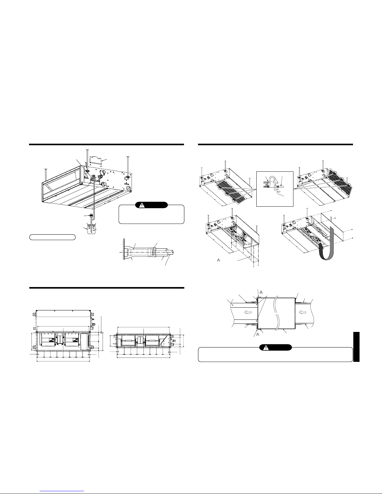
4
INSTALLATION OF INDOOR UNIT
WARNING
Install the air conditioner certainly to sufficiently withstand the weight.
If the strength is insufficient, the unit may fall down resulting in human injury.
Perform a specified installation work to guard against strong wind or earthquake.
An incomplete installation can cause accidents by the units falling and dropping.
REQUIREMENT
Strictly comply with the following rules to prevent damage of the indoor units and human injury.
• Do not put a heavy article on the indoor unit. (Even units are packaged)
• Carry in the indoor unit as it is packaged if possible. If carrying in the indoor unit unpacked by necessity, be
sure to use buffering cloth, etc. to not damage the unit.
• To move the indoor unit, hold the hooking metals (4 positions) only.
Do not apply force to the other parts (refrigerant pipe, drain pan, foamed parts, or resin parts, etc.).
• Carry the package by two or more persons, and do not bundle it with PP band at positions other than
specified.
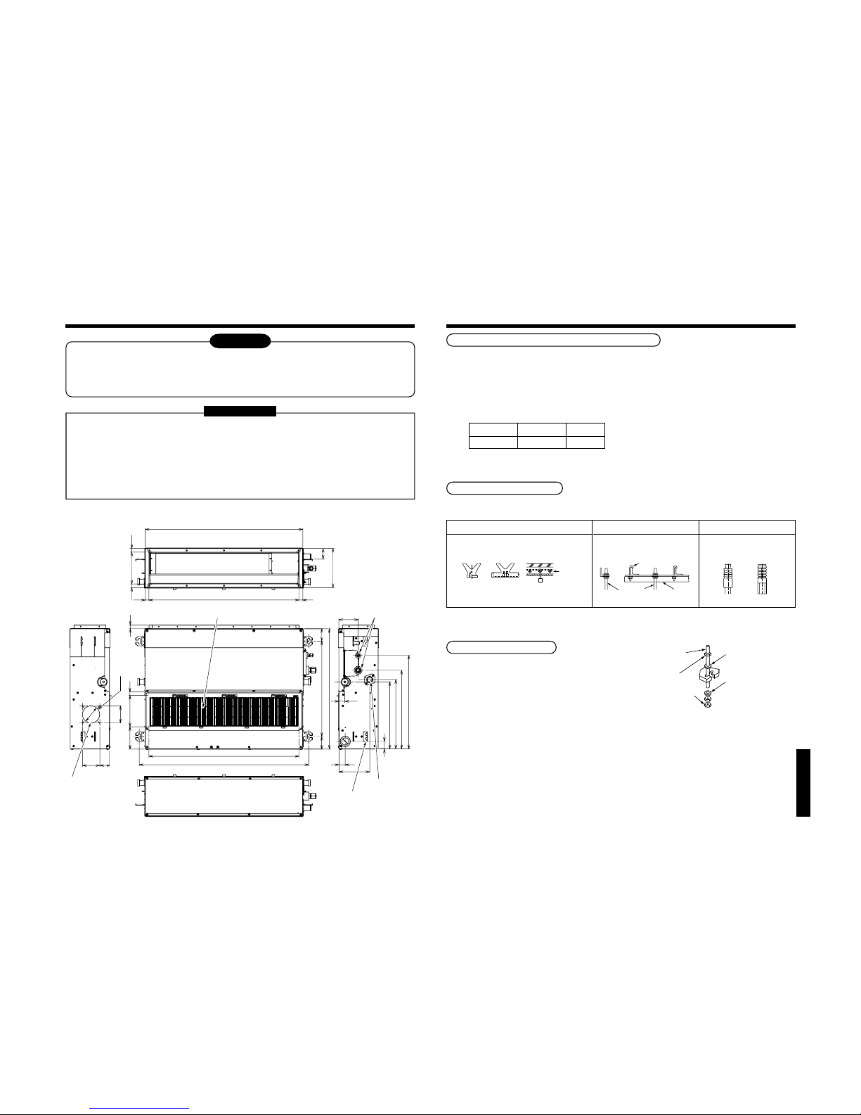
External view
511
67
67
910
372
359
422
502
103
31
163
33
40
21
803 (inside)
57
210
845
168
(inside)
21
21
21
120
805
19
645
168
20
Air filter
Refrigerant piping
Drain-up port
Hung-up plate
Fresh air inlet
(knock-out hole)
80
59
80
4-Ø4
Ø92
Anchor bolt
(Blade type
bracket)
(Slide type
bracket)
(Pipe hanging
anchor bolt)
Reinforcing
steel
Hanging bolt
Hanging bolt Support angle
Hanging bolt
Nut
M10 or W3/8
M10 or W3/8
4 pieces
12 pieces
Installation of hanging bolt
Use M10 hanging bolts (4 pcs, to be local procure).
Matching to the existing structure, set pitch according to size in the unit external view as shown below.
New concrete slab
Install the bolts with insert brackets or anchor
bolts.
Steel flame structure
Use existing angles or install new
support angles.
Existing concrete slab
Use a hole-in anchors, hole-in
plugs, or a hole-in bolts.
Opening hole on ceiling and placing of hanging bolt
• Considering the indoor unit and the hanged-up piping/wiring work, determine the installation position and direction.
• After installation position of the indoor unit has been determined, open a hole on the wiring and place the hanging bolt.
• For opening size of the ceiling and the hanging bolt pitch, see the external view.
• When the ceiling has already boarded, draw the drain pipe, refrigerant pipe, inter-unit wire between indoor and
outdoor units, central control system wire, and remote controller wire up to the position where pipes and wires are
connected before hanged-up the indoor unit.
The hanging bolts and nuts will be procured locally.
Hanging bolt
(W3/8 or M10)
Nut
(W3/8 or M10)
(1)Required those other than M10 flat washer at site.
(2)To prevent falling-off of bolt (safety), be sure to set it
just under the hanging bracket as shown in the figure.
(1)
M10 flat washer
(Accessory)
(2)
M10 flat washer
(Accessory)
Nut
(W3/8 or M10)
Installation of indoor unit
• Attach the nuts (M10 or W3/8: Procured locally) and
the attached washers (Ø34) to the hanging bolt.
• Put washers at up and down of T-groove of the
hanging bracket of the indoor unit to hang down the
indoor unit.
• Using a level vial, check that four sides are
horizontal. (Horizontal degree: Within 5mm)
23
“SPH” series
5
DRAIN PIPING WORK
CAUTION
• Following the Installation Manual, perform
the drain piping work so that water is
properly drained, and apply a heat
insulation so as not to cause a dew.
Inappropriate piping work may result in
water leakage in the room and wet of
furniture.
Pipe material/Insulator and size
The following materials for piping work and insulating
process are procured locally.
Pipe material
Insulator
Hard vinyl chloride pipe socket for VP25
Hard vinyl chloride pipe VP25
(Nominal outer diameter Ø32mm)
Foamed polyethylene foam, thickness:
10mm or more
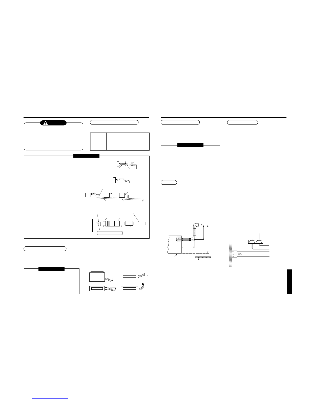
REQUIREMENT
• Be sure to perform heat insulation of the drain pipes of the indoor unit.
• Never forget to perform heat insulation of the connecting part with the
indoor unit. An incomplete heat insulation causes dewing.
• Set the drain pipe with downward slope (1/100 or more), and do not
make swelling or trap on the piping. It may cause an abnormal sound.
• For length of the traversing drain pipe, restrict to 20m or less.
In case of a long pipe, provide support brackets with interval of
1.5 to 2m in order to prevent waving.
• Set the collective piping as shown in the right figure.
• Do not mount an air purge pipe,
otherwise drain water spouts
out resulted in water leak.
• The hard vinyl-chloride pipe cannot be directly
connected to the drain pipe connecting port of
the indoor unit. For connection with the drain
pipe connecting port, be sure to fix the attached
flexible hose.
• Adhesive agent cannot be used for the pipe
connecting port (hard socket) of the indoor unit.
Be sure to use the attached hose band for
fixing, otherwise damage or water leakage of
the drain pipe connecting port is caused.
Connection of flexible hose
• Insert the soft socket of the attached flexible hose into the connecting port of the drain pipe until it strikes against
the end.
• Align the attached hose band to the end of the pipe connecting port, and then tighten it surely.
REQUIREMENT
• Be sure to fix the soft socket with the
attached hose band and set the
tightening position at upper side.
• Use the attached flexible hose by
bending it with 45° or less so that no
breakage or clogging occurs.
As long as possible (100mm or more)
VP30 or more
Downward slope
1/100 or more
VP25
VP25
VP25
(Collective pipes)
Align the attached hose band to the
end of hose, set the tightening
position upward, and then tighten it.
Drain pipe connecting port
(Hard socket)
Ø25 vinyl chloride pipe
(Local supply)
Adhesive agent prohibited
Soft socket Hard socket
Socket for VP25
(Local supply)
Indoor unit
Tra p
Arched
shape
Support
bracket
1/100 or more
downward
Heat
insulator
1.5m to 2m
NO
GOOD
max
45˚
Riser (Trap)
90˚ Bend
max
45˚
OK NO GOOD
Top view
Air outlet
Side view
Side viewSide view
Air outlet
Air outlet
Rising up
687mm or less
Rising up 850mm or less
300mm
or less
Indoor unit
Underneath of ceiling
220–240V ~, 50Hz
220V
~
, 60Hz
White
Black
CN34
(RED)
Black
Red
Pull out connector CN34 (Red) from P.C. board.
R(L) S(N)
Connection of drain pipe
• Connect the hard socket (local supply) to the hard
socket side of the attached flexible hose which has
been installed.
• Connect the drain pipes (local supply) successively
to the connected the hard socket.
REQUIREMENT
• Using adhesive agent for vinyl chloride, connect
the hard vinyl chloride pipes certainly so that
water does not leak.
• It requires several times to dry and harden the
adhesive agent.
(Refer to Guide Manual of the adhesive agent.)
In this time, be sure not to apply force to the
connecting section with the drain pipes.
Drain up
When a downward grading cannot be secured on the
drain pipe, a drain-up work is possible.
• Set the height of the drain pipe within 850mm from
the bottom surface of the indoor unit.
• Draw out the drain pipe within 300mm from the end
of the drain pipe connecting port of the indoor unit,
and then raise it vertically.
• After the drain pipe has been raised, set a grading
so that it is immediately bent downward.
Check the draining
After drain piping work, check that water drain is
properly performed and water does not leak from the
connecting part of the pipes. In this time, check also
there is no abnormal sound of the motor of the drain
pump. Be sure to check draining when installed in the
heating period.
When the electric work has finished:
• Pour water as shown in the following figure, check
water is drained from the drain pipe connecting port
in COOL mode, and then check there is no water
leak from the drain pipes.
When the electric work has not finished:
• Pull out the float switch connector (3P: Red) from
P.C. board connector (CN34: Red) of the electric
parts box. (In this time, be sure to check the power
is turned off.)
• Connect the single-phase 220-240V 50Hz (or 220V
60Hz) power to the terminal blocks R (L) and S (N).
(Never apply 220-240V to (A), (B), (U1),and (U2),
otherwise a trouble of P.C. board occurs.)
• Pour water referring to the figure.
(Amount: 1500cc to 2000cc)
• When the power is turned on, the drain pump motor
drives automatically.
Check water is drained from the drain pipe
connecting port, and then check there is no water
leak from the drain pipes.
• After check of draining and water leak, turn off the
power supply, attach the float switch connector to
the original position (CN34) of P.C. board, and then
set the electric parts box as before.
24
“SPH” series
Flexible hose
Hose band
Attached heat insulator
Heat insulator to be
procured locally
Hard vinyl chloride pipe
Insert the edge of hose into the
drain pan and bend it downward.
Pump
Vessel
Water
(1500cc~2000cc)
Cover plate
CAUTION
Pour water slowly.
If it is poured urgently, water is spread inside
of the indoor unit resulted in a trouble.
5
DRAIN PIPING WORK
Heat insulating process
• After drain check, using the attached heat insulator
for drain connecting section, wrap the flexible hose
without clearance from the end of the drain pipe
connecting port of the indoor unit.
• Covering the attached heat insulator for drain
connecting section, wrap the drain pipe with heat
insulator (local supply) without clearance.
6
AIR DUCTING
6-1. Arrangement
Referring to the following dimensions, manufacture duct at the local site.
<Under air inlet> <Back air inlet>
825
100
12.5
100100
12.5
44.3 100 44.3
188
825
286.8
8.2 or less
45.3 41.5100100
100100
12.5
100
12.5
100100
805
100 100 100
170
100 100
266
100100100
805
Remove the cover plate and
then fix it to the bottom surface.
Remove the filter from the
main unit while pushing
down on the tabs.
Force
Air filter
Main unit
CAUTION
Take out this cover plate.
Air inlet sideAir outlet side
Indoor unit
Aluminum tape (Local supply)
Aluminum tape (Local supply)
Duct:Insulation material
(Local supply)
Aluminum tape
(Local supply)
Under surface
Cover a screw
Flange
Connect a duct to the
inside of the flange
Heat insulator with sticking material (100mm-width Local supply)
Heat insulator with sticking material (100mm-width Local supply)
Aluminum tape (Local supply)
Flange (Local supply)
6-2. Connecting method of the duct
CAUTION
Incomplete heat insulation of the supply air flange and sealing may occur dewing resulted in falling of water
drop.
Be sure to mount an air filter to the air inlet side; otherwise decrease of capacity and etc. may be caused.
<Under air inlet> <Back air inlet>
25
“SPH” series
7
REFRIGERANT PIPING
WARNING
• If refrigerant gas has leaked during the installation work, ventilate the room immediately.
• If the leaked refrigerant gas comes in contact with fire, noxious gas may generate.
• After the installation work, confirm that refrigerant gas does not leak.
• If refrigerant gas leaks into the room and flows near a fire source, such as a cooking range, noxious gas may
generate.
REQUIREMENT
When the refrigerant pipe is long, set the support brackets to fix the pipe with 2.5 to 3m intervals. If the pipe is
not fixed, abnormal sound may generate.
Be sure to use the flare nuts attached to the indoor unit or those fro R410A.
Permissible pipe length and permissible height difference
They are different according to the used outdoor unit. For details, refer to the Installation Manual attached to the
outdoor unit.
Piping material and dimensions
Piping material
Model MMD-
Pipe size (mm)
Gas side
Liquid side
Phosphor deoxidization joint-less pipe for air conditioner
AP007 to AP012 AP015 to AP018
Ø9.5 Ø12.7
Ø6.4 Ø6.4
• Use a clean and new pipe, and check that impurity such as dust, oil, moisture, etc. does not adhere in the pipe.
Pipe forming/End positioning
Flaring
1. Cut the pipe with a pipe cutter.
2. Insert a flare nut into the pipe, and flare the pipe.
As the flaring sizes of R410A differ from those of
refrigerant R22, the flare tools newly manufactured
for R410A are recommended.
However, the conventional tools can be used by
adjusting projection margin of the copper pipe.
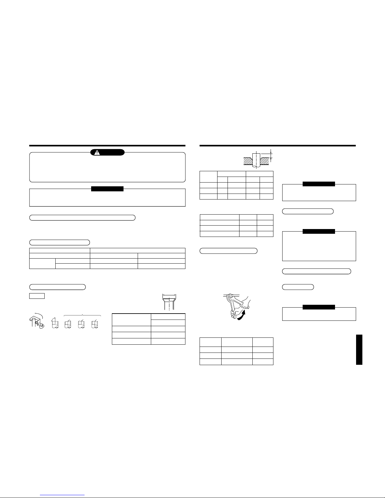
• Flaring diam. meter size :
A (Unit : mm)
*
In case of flaring for R410A with the conventional
flare tool, pull it out approx. 0.5 mm more than that
for R22 to adjust to the specified flare size.
The copper pipe gauge is useful for adjusting
projection margin size.
90˚
Obliquity Roughness Warp
NO GOODOK
A
+0
- 0.4
Outer diam. of
copper pipe
6.4
9.5
12.7
A
R410A
9.1
13.2
16.6
B
Work using double spanner
• Projection margin in flaring :
B (Unit : mm)
Rigid (Clutch type)
Outer diam. of
copper pipe
6.4
9.5
12.7
R410A tool used
R410A R22
0 to 0.5 (Same as left)
0 to 0.5 (Same as left)
0 to 0.5 (Same as left)
Conventional tool used
R410A R22
1.0 to 1.5 0.5 to 1.0
1.0 to 1.5 0.5 to 1.0
1.0 to 1.5 0.5 to 1.0
Imperial (Wing nut type)
Outer diam. of copper pipe
6.4
9.5
12.7
R410A R22
1.5 to 2.0 1.0 to 1.5
1.5 to 2.0 1.0 to 1.5
2.0 to 2.5 1.5 to 2.0
Connection of refrigerant pipe
Connect all the refrigerant pipes with flare connecting
work.
• Since the atmospheric pressure only is sealed
as the sealing gas, it is not abnormal that
“Pushu…” sound is not heard when the flare
nut is removed.
• Be sure to use a double spanner for pipe
connecting work of the indoor unit.
• Refer to the following table for tightening torque.
• Tightening torque of flare pipe connections
Pressure of R410A is higher than that of R22 by
approx. 1.6 times. Therefore, using a torque wrench,
tighten the flare pipe connecting sections which
connect the indoor and outdoor units of the specified
tightening torque. Incorrect connections may cause
not only a gas leak, but also a trouble of the
refrigerating cycle.
REQUIREMENT
If an excessive torque is applied, the nut
may crack depending on the installation
conditions.
Airtight test/Air purge, etc.
For airtight test, air purge, addition of refrigerant, and
gas leak check, follow the Installation Manual attached
to the outdoor unit.
REQUIREMENT
Be sure to use the tool such as charge hose
exclusive to R410A.
Do not turn on the power until the airtight test and
the vacuuming have finished. (If turning on the
power, the incorporated PMV is closed fully and
the period until the vacuuming finishes elongates.
Open fully valves of the outdoor unit
Gas leak check
Check with a leak detector or soap water whether gas
leaks or not, from the pipe connecting section or cap
of the valve.
REQUIREMENT
Use a leak detector manufactured exclusively for
HFC refrigerant (R410A, R134a, etc.).
Connecting pipe
outer dia. (mm)
Ø6.4
Ø9.5
Ø12.7
Tightening torque
(N•m)
14 to18 (1.4 to 1.8 kgf•m)
33 to 42 (3.3 to 4.2 kgf•m)
50 to 62 (5.0 to 6.2 kgf•m)
Re-tightening
torque (N•m)
18 (1.8 kgf•m)
42 (4.2 kgf•m)
62 (6.2 kgf•m)
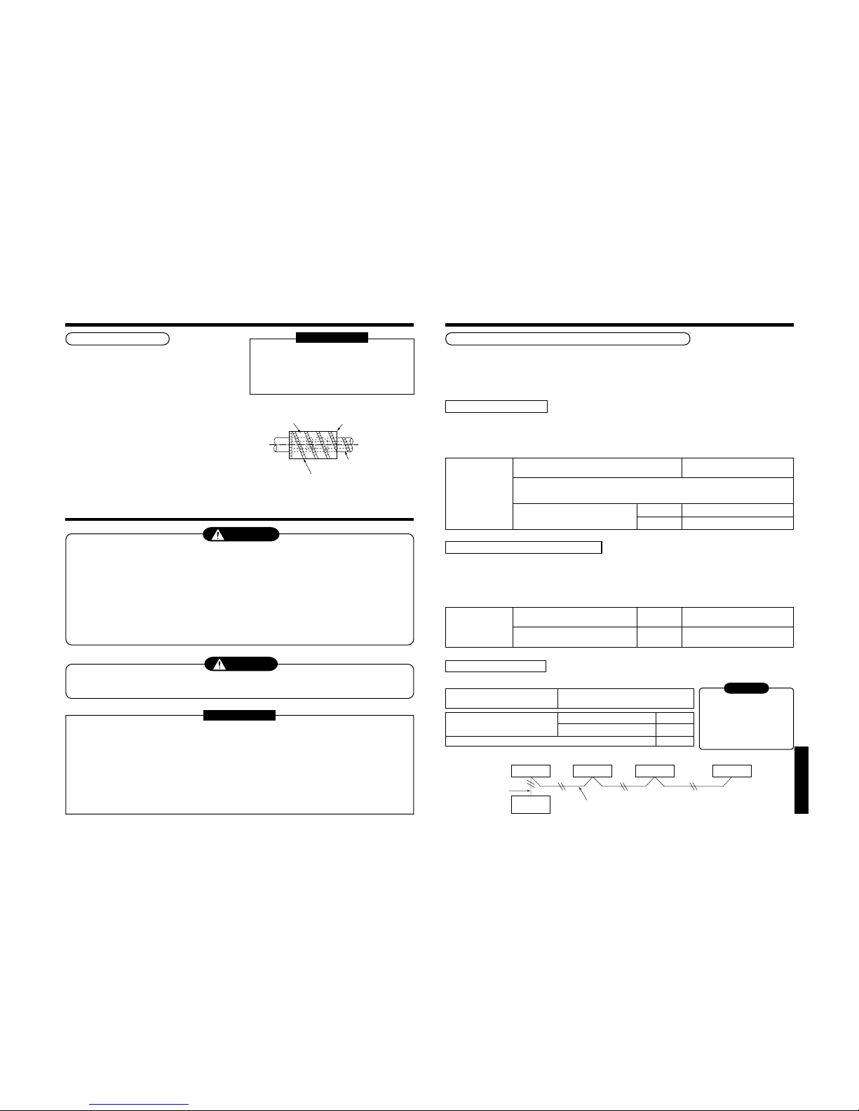
26
“SPH” series
Using tape,
fix the heat insulator.
Set notching upward.
Pipe side
(Required at the site)
Attached heat insulating pipe
Heat insulating process
Perform heat insulating for pipes at liquid side and gas
side separately.
In cooling time, temperature at both liquid and gas
sides becomes lower.
Therefore, perform heat insulating process sufficiently
to avoid dewing.
• For heat insulator of pipe at gas side, be sure to use
one with
heat-resisting temp.120°C or more.
• Using the attached heat insulating pipe, perform heat
insulating process
securely for pipe connecting part of the indoor units
without clearance.
REQUIREMENT
Apply the heat insulation to the pipe connecting
section of the indoor unit securely up to the root
without exposure of the pipe.
(The pipe exposed to the outside causes water
leak.)
8
ELECTRIC WORK
WARNING
1. Using the specified wires, ensure to connect the wires, and fix wires securely so that the
external strength of the wires do not transmit to the connecting part of the terminals.
Incomplete connection or fixation may cause a fire, etc.
2. Be sure to connect earth wire. (Grounding work)
Do not connect the earth wire to gas pipe, city water pipe, lightning rod, or the earth wire of telephone.
Incomplete grounding causes an electric shock.
3. For electric work, strictly follow to the Local Regulation in each country and the Installation
Manual, and use an exclusive circuit.
Capacity shortage of power circuit or incomplete installation may cause an electric shock or a fire.
CAUTION
Be sure to install an earth leakage breaker.
If an earth leakage breaker is not installed, an electric shock may be caused.
REQUIREMENT
• For power supply wiring, strictly conform to the Local Regulation in each country.
• For wiring of power supply of the outdoor units, follow to the Installation Manual of each outdoor unit.
• Never connect 220–240V power to the terminal blocks (A, B, U1, U2, X, Y, etc.) for control wiring.
(Otherwise, the system will be failed.)
• Perform the electric wiring so that it does not come to contact with the high-temperature part of the pipe.
The coating may melt resulted in an accident.
• After connecting wires to the terminal blocks, provide a trap and fix wires with the wire clamp.
• Store the refrigerant piping line and control wiring line in the same line.
• Do not turn on the power of the indoor unit until vacuuming of the refrigerant pipes completes.
7
REFRIGERANT PIPING
Power supply cord and communication wires specifications
Power supply cord and communication wires are procured locally.
For the power supply specifications, follow to the table below. If capacity is little, it is dangerous because overheat or
seizure may be caused.
For specifications of the power capacity of the outdoor unit and the power supply wires, refer to the Installation
Manual attached to the outdoor unit.
Indoor unit power supply
• For the power supply of the indoor unit, prepare the exclusive power supply separated from that of the outdoor unit.
• Arrange the power supply, earth leakage breaker, and main switch of the indoor unit connected to the same
outdoor unit so that they are commonly used.
• Power supply cord specification : Cable 3-core 2.5mm², in conformity with Design 60245 IEC 57.
Control wiring, Central controller wiring
• 2-core with polarity wires are used for the Control wiring between indoor unit and outdoor unit and Central
controller wiring.
• To prevent noise trouble, use 2-core shield wire.
• The length of the communication line means the total length of the inter-unit wire length between indoor and
outdoor units added with the central control system wire length.
CAUTION
The remote controller wire
(Communication line) and
AC220–240V wires cannot be
parallel to contact each other and
cannot be stored in the same
conduits. If doing so, a trouble
may be caused on the control
system due to noise, etc.
Remote controller inter-unit wiring
Indoor unit
Remote
controller
Indoor unit
L1 L2 Ln
(Max. 8 units)
Indoor unit Indoor unit
Remote
controller
wiring
Remote controller wiring
• 2-core with non-polarity wire is used for wiring of the remote controller wiring and group remote controllers wiring.
Power supply
Power supply
Power supply wiring
Below 20m
Below 50m
220–240V
~ 50Hz
220V
~ 60Hz
Twist wire : 2.0 mm²
Twist wire : 3.5 mm²
Power supply switch/Earth leakage breaker or power supply wiring/fuse rating for
indoor units should be selected by the accummulated total current values of the indoor units.
Communication line
Control wiring between indoor unit and
outdoor unit (2-core shield wire)
Central control line wiring
(2-core shield wire)
Wire size
Wire size
(Up to 1000m) Twist wire : 1.25 mm²
(Up to 2000m) Twist wire : 2.00 mm²
(Up to 1000m) Twist wire : 1.25 mm²
(Up to 2000m) Twist wire : 2.00 mm²
Up to 500m
Up to 400m
Up to 200m
Twist wire: 0.5mm
2
to 2.0mm2 × 2
Total wire length of remote controller
wiring and remote controller inter-unit
wiring = L + L1 + L2 + … Ln
In case of wired type only
In case of wireless type included
Remote controller wiring, remote
controller inter-unit wiring
Total wire length of remote controller inter-unit wiring = L1 + L2 + … Ln
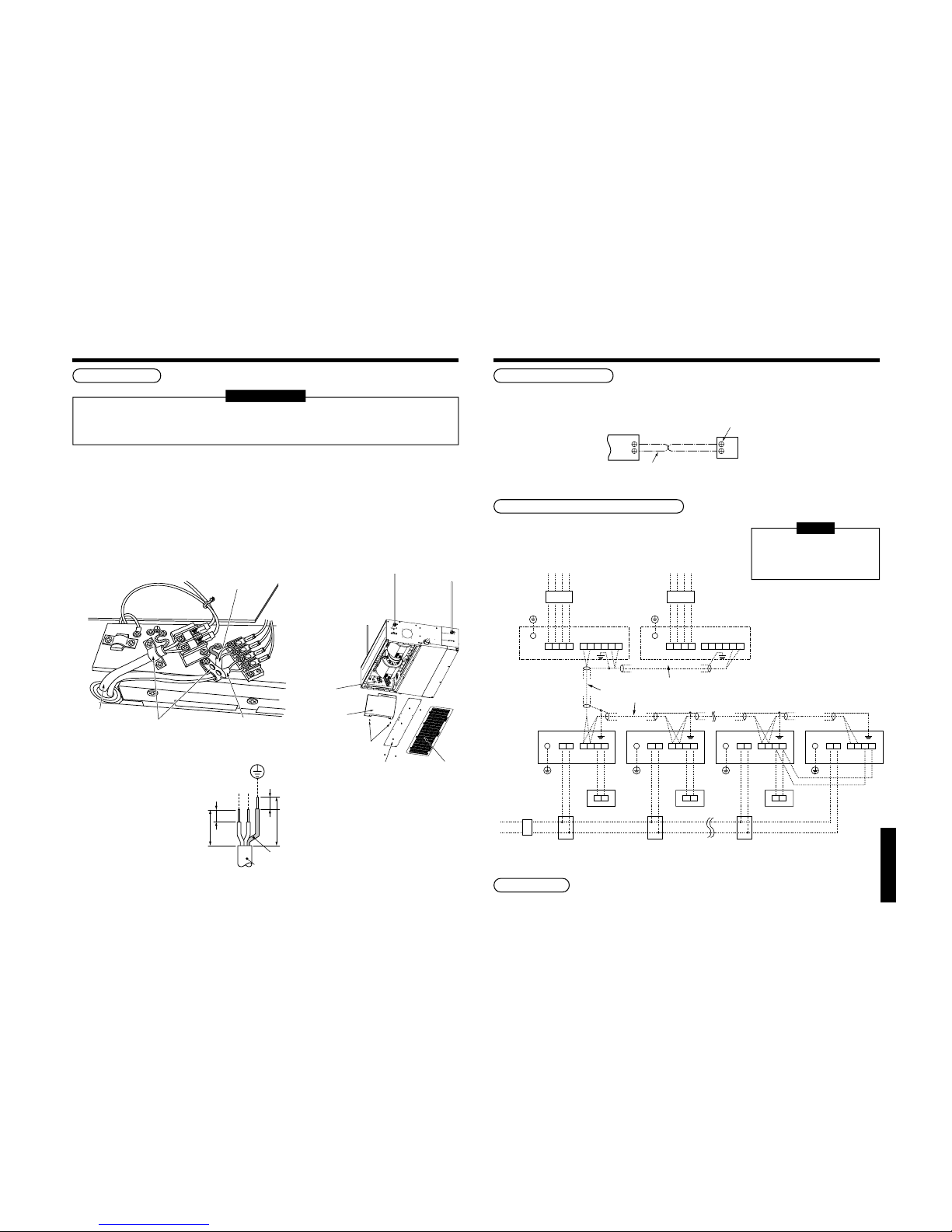
27
“SPH” series
Cable connection
REQUIREMENT
• Be sure to pass the wire through the wire connection port of the indoor unit.
• Keep a margin (Approx. 100mm) on a wire to hang down the electric parts box at servicing, etc.
• The low-voltage circuit is provided for the remote controller.
• Before remove the electric parts cover, remove the cover plate and air filter.
• Remove the cover of the electric parts box by taking off the mounting screws (2 positions) and pushing the
hooking section. (The cover of the electric parts box remains hanged to the hinge.)
• Tighten the screws of the terminal block, and fix the wires with cord clamp attached to the electric parts box.
(Do not apply tension to the connecting section of the terminal block.)
• Be sure to set a loop for the connecting wire of the storing part of the indoor unit electric parts; otherwise the
electric parts box cannot be drawn out in service time.
• Mount the cover of the electric parts box without pinching wires.
R
(L)S(N)
10
10
30
70
Earth line
Power supply cord
Screw
(2 positions)
Electric
parts box
Electric parts
box cover
Air filter
Cover plate
R
(L
)
S
(N
)
Control wire
Remote controller wire
Cable cramp
Power supply cord
8
ELECTRIC WORK
Remote controller wiring
• As the remote controller wire has no polarity, there is no problem if connections to indoor unit terminal blocks A
and B are reversed.
<Wiring diagram>
Address setup
Set up the addresses according to the Installation Manual attached to the outdoor unit.
Wiring between indoor and outdoor units
<Wiring example>
NOTE
An outdoor unit connected with
control wiring between indoor and
outdoor units wire becomes
automatically the header unit.
Terminal block for
remote controller
wiring of indoor unit
A
B
Remote controller wire
(Field supply)
Remote
controller unit
A
B
Terminal block
Indoor power supply
220-240V, ~50Hz
220V~60Hz
Outdoor Power supply
380V-415V ~ 50Hz
380V ~ 60Hz
Earth leakage
breaker
Header outdoor unit
Indoor unit
Remote controller
Pull box
Earth leakage breaker
power switch
Pull box Pull box
Header outdoor unit
Earth leakage
breaker
Control wiring between indoor and outdoor units
Earth
Earth
terminal
U1 U2
U1 U2 U3 U4L1 L2 L3 N U5 U6
L N A B
A B
Control wiring between outdoor units
Outdoor Power supply
380V-415V ~ 50Hz
380V ~ 60Hz
Earth
terminal
U1 U2 U3 U4L1 L2 L3 N U5 U6
Control wiring between indoor units
Indoor unit
Remote controller
Earth
U1 U2L N A B
A B
Indoor unit
Remote controller
Earth
U1 U2L N A B
A B
Indoor unit
Earth
U1 U2L N A B
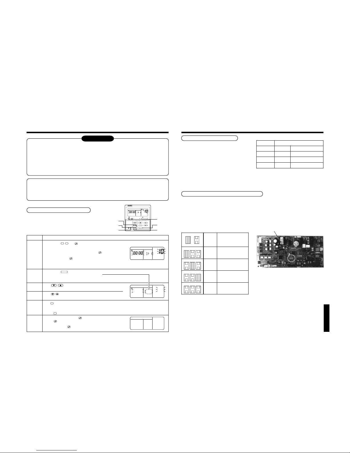
28
“SPH” series
9
APPLICABLE CONTROLS
NOTIFICATION
When using the equipment at the first time, it will take a lot of time that the remote controller accepts an
operation after power was on. However, it is not a trouble.
• Automatic address
• While automatic addressing, the operation cannot be performed on the remote controller.
• For automatic addressing, Max. 10 minutes (generally, approx. 5 minutes) are required.
• When power will be turned on after finish of automatic addressing;
• It will require Max. 10 minutes (generally, approx. 3 minutes) that outdoor unit starts operation after power
was on.
As all have been set to [Standard] at the shipment, change the setup of the indoor unit if necessary.
To change the setup, use the main remote controller (wired remote controller).
* The setup change for wireless remote controller, sub remote controller, or remote controller-less system
(Central control remote controller only is provided.) is impossible. In these cases, prepare and mount a
separate main remote controller.
Exchange of applicable control setup
Basic operation procedure for setup exchange
Change the setup while operation of the equipment stops.
(Be sure to stop the operation of a set.)
Procedure
1
2
3
4
5
6
Description
When pushing
SET, CL
, and
TES
T
buttons simultaneously for 4 seconds or more, after a while, the display part
flashes as shown in the figure.
Check that the displayed item code is [10].
• If the item code indicates other than [10], push
TES
T
button to erase
the display, and then retry the operation from the first step.
(For some time after
TES
T
button has been pushed, the operation of
the remote controller cannot be accepted.)
(In a group control, the firstly displayed
indoor unit No. becomes the header unit.)
Every pushing
UNIT
button, the indoor unit No. in the group control is displayed successively.
Select an indoor unit of which setup to be changed.
In this time, the position of the indoor unit of which setup to be changed can
be confirmed because the fan and the flap of the selected indoor unit work.
Using , buttons of set temperature, specify the item
code [
**
].
Using , buttons of timer time, select set data [
****
].
Push
SET
button. In this time, if the display changes from flashing to lighting, the setup completes.
• To change the setup of an indoor unit other than the selected one, start operation from Procedure
2
.
• To change the setup of another setup in the selected indoor unit, start operation from Procedure
3
.
Pushing
CL
button clears the set up contents which have been already set. In this case, retry from Procedure 2.
When the setup finished, push
TES
T
button. (The setup is determined.)
Pushing
TES
T
button deletes the display and returns the status to
normal stop status.
(For some time after
TES
T
button has been pushed, the operation of the
remote controller cannot be accepted.)
(* The display changes according
to the indoor unit model.)
ON / OFF
FAN
TEMP.
SWING/FIXTIME
MODE
VENT
UNITSET CL
FILTER
RESET
TEST
TIMER SET
CODE No.
UNIT No.
R.C. No.
1
2
3
5
4
6
CODE No.
UNIT No.
R.C. No.
∗
∗∗
∗∗
∗
∗∗∗∗∗
CODE No.
UNIT No.
SETTING
R.C. No.
Short plug position
Set data External static pressure
0000
10 Pa (At shipment)
0001
20 Pa
0003
35 Pa
0006
50Pa
Shor
t
C
N11
2
C
N11
1
C
N11
0
Ope
n
C
N11
2
C
N11
1
C
N11
0
C
N11
2
C
N11
1
C
N11
0
C
N11
2
C
N11
1
C
N11
0
Setup of external static pressure
Be sure to set up a tap change based upon the
resistance (external static pressure) of the duct to be
connected.
To set up a tap change, follow to the basic operation
procedure (
1
→ 2 → 3 → 4 → 5 → 6 ).
• Specify [5d] to the item code in procedure
3
.
• For the setup data of procedure
4
, select a setup
data of the external static pressure to be set up from
the following table.
<Change on wired remote controller>
Setup data
0000
0001
0003
0006
External static pressure
10 Pa Standard (At shipment)
20 Pa High static pressure 1
35 Pa High static pressure 2
50 Pa High static pressure 3
In case of remote controller-less (Group control)
For setup to the high ceiling, there is selecting method by exchanging the short plugs on the indoor microcomputer
P.C. board as shown in the following table other than selecting method by standard wired remote controller (sold
separately). Utilize this method for remote controller-less (Group control) case.
∗ However, when the setup to high ceiling has been once exchanged, it is required for returning it to 0000 to change
the short plug to the standard (at shipment) position and rewrite data to the setup data 0000 from the wired remote
controller sold separately though setup to 0001, 0003 or 0006 are freely available.
• Select by exchange of short plugs on the indoor
P.C. board.
• Short plug position
(CN112, CN111, CN110 from the left)
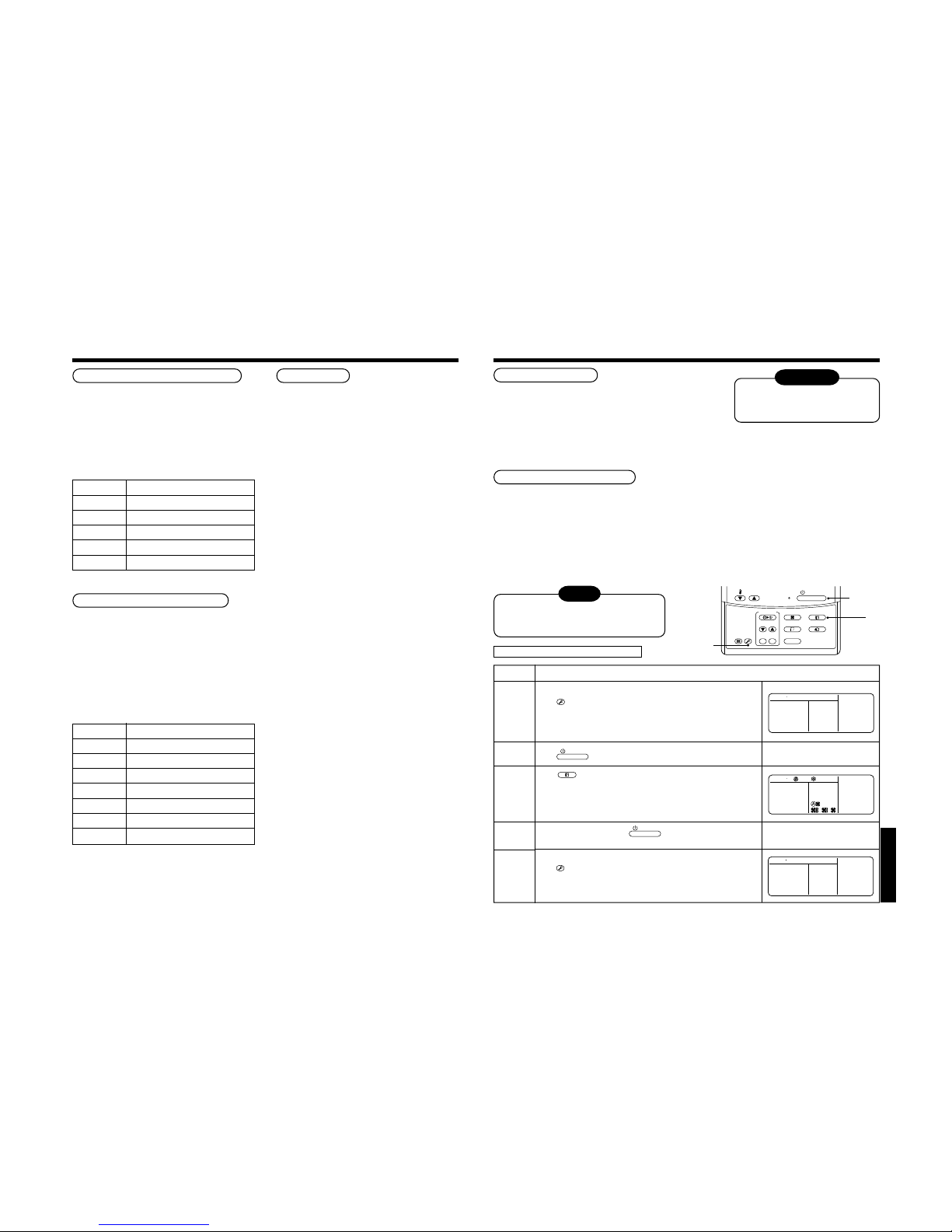
29
“SPH” series
Change of lighting term of filter sign
According to the installation condition, the lighting term
of the filter sign (Notification of filter cleaning) can be
changed.
Follow to the basic operation procedure
(
1
→ 2 → 3 → 4 → 5 → 6 ).
• For the item code in Procedure
3
, specify [01].
• For the [Set data] in Procedure
4
, select the setup
data of filter sign lighting terme from the following
table.
Setup data
0000
0001
0002
0003
0004
Filter sign lighting term
None
150H
2500H (At shipment from factory)
5000H
10000H
To secure better effect of heating
When it is difficult to obtain satisfactory heating due to
installation place of the indoor unit or structure of the
room, the detection temperature of heating can be
raised. Also use a circulator, etc. to circulate heat air
near the ceiling.
Follow to the basic operation procedure
(
1
→ 2 → 3 → 4 → 5 → 6 ).
• For the item code in Procedure
3
, specify [06].
• For the set data in Procedure
4
, select the setup
data of shift value of detection temperature to be set
up from the table below.
Setup data
0000
0001
0002
0003
0004
0005
0006
Detection temp shift value
No shift
+1°C
+2°C (At shipment from factory)
+3°C
+4°C
+5°C
+6°C
Group control
In a group control, a remote controller can control up
to maximum 8 units.
• For cabling procedure and cables of the individual
line (Identical refrigerant line) system, refer to
“Electric work” in this Manual.
• Cabling between indoor units in a group is performed
in the following procedure.
Connect the indoor units by connecting the remote
controller inter-unit cables from the remote controller
terminal blocks (A, B) of the indoor unit connected
with a remote controller to the remote controller
terminal blocks (A, B) of the other indoor unit.
(No polarity)
• For address setup, refer to the Installation Manual
attached to the outdoor unit.
9
APPLICABLE CONTROLS
NOTE
Do not use a forced operation in cases other
than test operation because it applies an
excessive load to the air conditioner.
In case of wired remote controller
Procedure
1
2
3
4
5
Description
Keep
TES
T
button pushed for 4 seconds or more.
[TEST] is displayed on the display part and the selection of mode in
the test mode is permitted.
Push
ON / OFF
button.
Using
MODE
button, select the operation mode, [COOL] or [HEAT].
• Do not run the air conditioner in a mode other than [COOL] or [HEAT].
• The temperature controlling function does not work during test
operation.
• The detection of error is performed as usual.
After the test operation, push
ON / OFF
button to stop the operation.
(Display part is same as procedure
1
)
Push
TES
T
button to cancel (release from) the test operation mode.
([TEST] disappears on the display part and the status returns to a
normal stop status.)
10
TEST RUN
Before test operation
• Before turning on the power supply, carry out the following items.
1) Using 500V-megger, check there is 1MΩ or more between the
terminal block of the power supply and the earth. If 1MΩ or less
is detected, do not run the unit.
2) Check that all the valves of the outdoor unit are fully opened.
• Never push the electromagnetic contactor to carry out a forced test operation.
(It is very dangerous because a protective device does not work.)
How to execute test operation
• To carry out a fan operation in a single indoor unit, turn off the power once, short CN72 on P.C. board, and then
turn on the power again. (Start the unit in FAN mode.) In this case, do not forget to clear short-circuit of CN72 after
test operation.
• Using the remote controller, check the operation in the usual operation. For the operation procedure, refer to the
attached Owner’s Manual.
A forced test operation can be executed in the following procedure under condition of thermo-OFF of room
temperature.
In order to prevent a serial operation, the forced test operation is released after 60 minutes and returns to the
usual operation.
WARNING
To protect the compressor at
starting time, keep power-ON
condition before 12 hours or more.
1, 5
3
2, 4
ON / OFF
FAN
TEMP.
SWING/FIXTIME
MODE
VENT
UNITSET CL
FILTER
RESET
TEST
TIMER SET
TEST
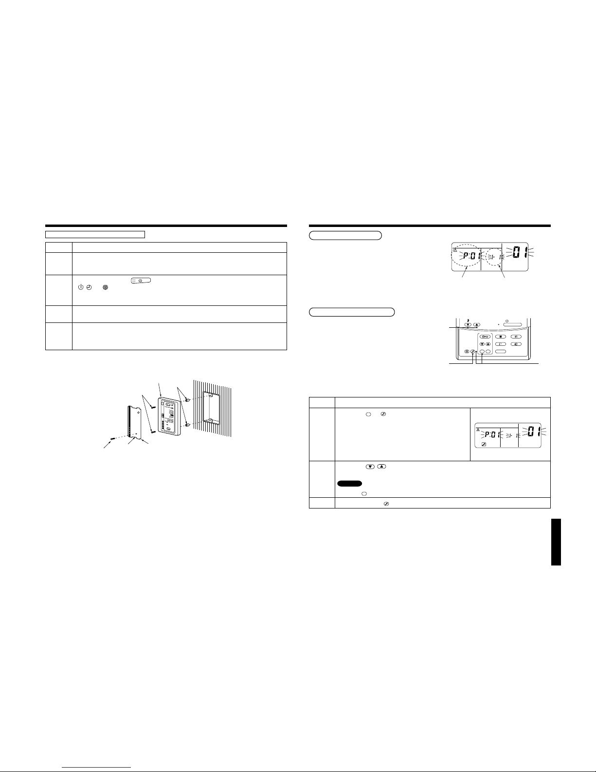
30
“SPH” series
Receiver unit
M4 × 25 screw
(2 pieces)
Small screw
Spacer
Notch
Nameplate
In case of wireless remote controller
Procedure
1
2
3
4
Description
Remove a small screw which fixes the nameplate of the receiver unit.
Remove the nameplate of the sensor section by inserting a minus screwdriver, etc into the notch at the bottom
of the plate, and set the Dip switch to [TEST RUN ON].
Execute a test operation with button on the wireless remote controller.
•
, , and LED flash during test operation.
• Under status of [TEST RUN ON], the temperature adjustment from the wireless remote controller is invalid.
Do not use this method in the operation other than test operation because the equipment is damaged.
Use either COOL or HEAT operation mode for a test operation.
* The outdoor unit does not operate approx. 3 minutes after power-ON and operation stop.
After the test operation finished, stop the air conditioner from the wireless remote controller, and return Dip
switch of the receiver section as before.
(A 60-minutes timer clearing function is attached to the receiver section in order to prevent a continuous test
operation.)
10
TEST RUN
11
TROUBLESHOOTING
Confirmation and check
When a trouble occurred in the air conditioner, the
check code and the indoor unit No. appear on the
display part of the remote controller.
The check code is only displayed during the operation.
If the display disappears, operate the air conditioner
according to the following “Confirmation of error
history” for confirmation.
Confirmation of error history
When a trouble occurred on the air conditioner, the
error history can be confirmed with the following
procedure.
(The error history is stored in memory up to 4 errors.)
This history can be confirmed from either operating
status or stop status.
Procedure
1
2
3
Description
When pushing
SET
and
TES
T
buttons simultaneously for 4 seconds or
more, the right display appears.
If [Service Check] is displayed, the mode enters in the error history
mode.
• [01: Order of error history] is displayed in CODE No. window.
• [Check Code] is displayed in CHECK window.
• [Indoor unit address in which an error occurred] is displayed in
UNIT No.
Every pushing , buttons, the error history stored in the memory is displayed in order.
The numbers in CODE No. indicates CODE No. [01] (Latest) → [04] (Oldest).
CAUTION
Do not push
CL
button because all the error history of the indoor unit will be deleted.
After confirmation, push
TES
T
button to return to the usual display.
CODE No.
UNIT No.
R.C. No.
Check code Indoor unit No. in which
an error occurred
3
2
1
ON / OFF
FAN
TEMP.
SWING/FIXTIME
MODE
VENT
UNITSET CL
FILTER
RESET
TEST
TIMER SET
CODE No.
UNIT No.
R.C. No.
 Loading...