

Toshiba MMC-AP0157HP-E, MMC-AP0247HP-E, MMC-AP0187HP-E, MMC-AP0277HP-E, MMC-AP0367HP-E Installation Manual
...
AIR CONDITIONER (MULTI TYPE)
Installation Manual
English
Indoor Unit
Model name:
Ceiling Type
MMC-AP0157HP-E
MMC-AP0187HP-E
MMC-AP0247HP-E
MMC-AP0277HP-E
MMC-AP0367HP-E
MMC-AP0487HP-E
MMC-AP0567HP-E
For commercial use
.
– 1 –
Original instruction
Please read this Installation Manual carefully before installing the Air Conditioner.
• This Manual describes the installation method of the indoor unit.
• For installation of the outdoor unit, follow the Installation Manual attached to the outdoor unit.
ADOPTION OF NEW REFRIGERANT
This Air Conditioner uses R410A an environmentally friendly refrigerant.
Contents
1 Precautions for safety .................................................................................................... 3
2 Accessory parts ..............................................................................................................5
3 Selection of installation place ...................................................................................... 5
4 Installation ...................................................................................................................... 6
5 Drain piping ..................................................................................................................... 9
6 Refrigerant piping ......................................................................................................... 11
7 Electrical connection ....................................................................................................12
8 Applicable controls ..................................................................................................... 14
9 Test run ......................................................................................................................... 16
10 Maintenance .................................................................................................................17
11 Troubleshooting ........................................................................................................... 18
12 Specifi cations .............................................................................................................. 23
1-EN 2-EN
Thank you for purchasing this Toshiba air conditioner.
Please read carefully through these instructions that contain important information which complies with the
“Machinery” Directive (Directive 2006/42/EC), and ensure that you understand them.
After completing the installation work, hand over this Installation Manual as well as the Owner’s Manual provided to
the user, and ask the user to keep them in a safe place for future reference.
Generic Denomination: Air Conditioner
Defi nition of Qualifi ed Installer or Qualifi ed Service Person
The air conditioner must be installed, maintained, repaired and removed by a qualifi ed installer or qualifi ed service
person. When any of these jobs is to be done, ask a qualifi ed installer or qualifi ed service person to do them for
you. A qualifi ed installer or qualifi ed service person is an agent who has the qualifi cations and knowledge described
in the table below.
Agent Qualifi cations and knowledge which the agent must have
• The qualifi ed installer is a person who installs, maintains, relocates and removes the air conditioners
made by Toshiba Carrier Corporation. He or she has been trained to install, maintain, relocate and
remove the air conditioners made by Toshiba Carrier Corporation or, alternatively, he or she has
been instructed in such operations by an individual or individuals who have been trained and is thus
thoroughly acquainted with the knowledge related to these operations.
• The qualifi ed installer who is allowed to do the electrical work involved in installation, relocation
and removal has the qualifi cations pertaining to this electrical work as stipulated by the local laws
and regulations, and he or she is a person who has been trained in matters relating to electrical
work on the air conditioners made by Toshiba Carrier Corporation or, alternatively, he or she has
Qualifi ed
installer
Qualifi ed
service person
been instructed in such matters by an individual or individuals who have been trained and is thus
thoroughly acquainted with the knowledge related to this work.
• The qualifi ed installer who is allowed to do the refrigerant handling and piping work involved in
installation, relocation and removal has the qualifi cations pertaining to this refrigerant handling
and piping work as stipulated by the local laws and regulations, and he or she is a person who
has been trained in matters relating to refrigerant handling and piping work on the air conditioners
made by Toshiba Carrier Corporation or, alternatively, he or she has been instructed in such matters
by an individual or individuals who have been trained and is thus thoroughly acquainted with the
knowledge related to this work.
• The qualifi ed installer who is allowed to work at heights has been trained in matters relating to
working at heights with the air conditioners made by Toshiba Carrier Corporation or, alternatively,
he or she has been instructed in such matters by an individual or individuals who have been trained
and is thus thoroughly acquainted with the knowledge related to this work.
• The qualifi ed service person is a person who installs, repairs, maintains, relocates and removes
the air conditioners made by Toshiba Carrier Corporation. He or she has been trained to install,
repair, maintain, relocate and remove the air conditioners made by Toshiba Carrier Corporation or,
alternatively, he or she has been instructed in such operations by an individual or individuals who
have been trained and is thus thoroughly acquainted with the knowledge related to these operations.
• The qualifi ed service person who is allowed to do the electrical work involved in installation, repair,
relocation and removal has the qualifi cations pertaining to this electrical work as stipulated by the
local laws and regulations, and he or she is a person who has been trained in matters relating to
electrical work on the air conditioners made by Toshiba Carrier Corporation or, alternatively, he or
she has been instructed in such matters by an individual or individuals who have been trained and is
thus thoroughly acquainted with the knowledge related to this work.
• The qualifi ed service person who is allowed to do the refrigerant handling and piping work involved
in installation, repair, relocation and removal has the qualifi cations pertaining to this refrigerant
handling and piping work as stipulated by the local laws and regulations, and he or she is a
person who has been trained in matters relating to refrigerant handling and piping work on the air
conditioners made by Toshiba Carrier Corporation or, alternatively, he or she has been instructed
in such matters by an individual or individuals who have been trained and is thus thoroughly
acquainted with the knowledge related to this work.
• The qualifi ed service person who is allowed to work at heights has been trained in matters relating
to working at heights with the air conditioners made by Toshiba Carrier Corporation or, alternatively,
he or she has been instructed in such matters by an individual or individuals who have been trained
and is thus thoroughly acquainted with the knowledge related to this work.
Defi nition of Protective Gear
When the air conditioner is to be transported, installed, maintained, repaired or removed, wear protective gloves
and ‘safety’ work clothing.
In addition to such normal protective gear, wear the protective gear described below when undertaking the special
work detailed in the table below.
Failure to wear the proper protective gear is dangerous because you will be more susceptible to injury, burns,
electric shocks and other injuries.
Work undertaken Protective gear worn
All types of work Protective gloves ‘Safety’ working clothing
Gloves to provide protection for electricians
Electrical-related work
Insulating shoes
Clothing to provide protection from electric shock
Work done at heights
(50 cm or more)
Transportation of
heavy objects
Helmets for use in industry
Shoes with additional protective toe cap
Repair of outdoor unit Gloves to provide protection for electricians
3-EN 4-EN
– 2 –
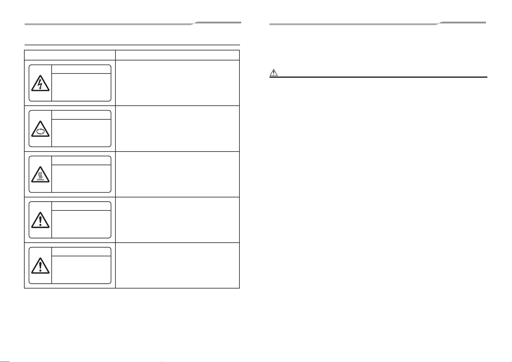
■
WARNING
ELECTRICAL SHOCK HAZARD
Disconnect all remote
electric power supplies
before servicing.
WARNING
Moving parts.
Do not operate unit with grille
removed.
Stop the unit before the
servicing.
CAUTION
High temperature parts.
You might get burned when
removing this panel.
CAUTION
Do not touch the aluminum
fi ns of the unit.
Doing so may result in injury.
CAUTION
BURST HAZARD
Open the service valves before
the operation, otherwise there
might be the burst.
Warning indications on the air conditioner unit
Warning indication Description
– 3 –
1 Precautions for safety
The manufacturer shall not assume any liability for the damage caused by not observing the description of this
manual.
WARNING
ELECTRICAL SHOCK HAZARD
Disconnect all remote electric power supplies before servicing.
WARNING
Moving parts.
Do not operate unit with grille removed.
Stop the unit before the servicing.
CAUTION
High temperature parts.
You might get burned when removing this panel.
CAUTION
Do not touch the aluminium fi ns of the unit.
Doing so may result in injury.
CAUTION
BURST HAZARD
Open the service valves before the operation, otherwise there
might be the burst.
WARNING
General
• Before starting to install the air conditioner, read through the Installation Manual carefully, and follow its instructions to
install the air conditioner.
• Only a qualifi ed installer (*1) or qualifi ed service person (*1) is allowed to do installation work. Inappropriate installation
may result in water leakage, electric shock or fi re.
• Do not use any refrigerant different from the one specifi ed for complement or replacement. Otherwise, abnormally high
pressure may be generated in the refrigeration cycle, which may result in a failure or explosion of the product or an injury
to your body.
• Before opening the intake grille of the indoor unit or service panel of the outdoor unit, set the circuit breaker to the OFF
position. Failure to set the circuit breaker to the OFF position may result in electric shocks through contact with the
interior parts. Only a qualifi ed installer (*1) or qualifi ed service person (*1) is allowed to remove the intake grille of the
indoor unit or service panel of the outdoor unit and do the work required.
• Before carrying out the installation, maintenance, repair or removal work, set the circuit breaker to the OFF position.
Otherwise, electric shocks may result.
• Place a “Work in progress” sign near the circuit breaker while the installation, maintenance, repair or removal work is
being carried out. There is a danger of electric shocks if the circuit breaker is set to ON by mistake.
• Only a qualifi ed installer (*1) or qualifi ed service person (*1) is allowed to undertake work at heights using a stand of 50
cm or more or to remove the intake grille of the indoor unit to undertake work.
• Wear protective gloves and safety work clothing during installation, servicing and removal.
• Do not touch the aluminium fi n of the unit. You may injure yourself if you do so. If the fi n must be touched for some
reason, fi rst put on protective gloves and safety work clothing, and then proceed.
• Before opening the intake grille, set the circuit breaker to the OFF position. Failure to set the circuit breaker to the OFF
position may result in injury through contact with the rotation parts. Only a qualifi ed installer (*1) or qualifi ed service
person (*1) is allowed to remove the intake grille and do the work required.
• When work is performed at heights, use a ladder which complies with the ISO 14122 standard, and follow the procedure
in the ladder’s instructions. Also wear a helmet for use in industry as protective gear to undertake the work.
• Before cleaning the fi lter or other parts of the outdoor unit, set the circuit breaker to OFF without fail, and place a “Work
in progress” sign near the circuit breaker before proceeding with the work.
• Before working at heights, put a sign in place so that no-one will approach the work location, before proceeding with the
work. Parts and other objects may fall from above, possibly injuring a person below. While carrying out the work, wear a
helmet for protection from falling objects.
• The refrigerant used by this air conditioner is the R410A.
• The air conditioner must be transported in stable condition. If any part of the product is broken, contact the dealer.
• When the air conditioner must be transported by hand, carry it by two or more people.
• Do not move or repair any unit by yourself. There is high voltage inside the unit. You may get electric shock when
removing the cover and main unit.
• To transport the air conditioner, wear shoes with additional protective toe caps.
• To transport the air conditioner, do not take hold of the bands around the packing carton. You may injure yourself if the
bands should break.
Selection of installation location
• When the air conditioner is installed in a small room, provide appropriate measures to ensure that the concentration of
refrigerant leakage occur in the room does not exceed the critical level.
• Do not install in a location where fl ammable gas leaks are possible. If the gas leak and accumulate around the unit, it
may ignite and cause a fi re.
• Install the indoor unit at least 2.5 m above the fl oor level since otherwise the users may injure themselves or receive
electric shocks if they poke their fi ngers or other objects into the indoor unit while the air conditioner is running.
• Do not place any combustion appliance in a place where it is directly exposed to the wind of air conditioner, otherwise it
may cause imperfect combustion
5-EN 6-EN
Installation
• When the indoor unit is to be suspended, the designated hanging bolts (M10 or W3/8) and nuts (M10 or W3/8) must be
used.
• Install the air conditioner securely in a location where the base can sustain the weight adequately. If the strength is not
enough, the unit may fall down resulting in injury.
• Follow the instructions in the Installation Manual to install the air conditioner. Failure to follow these instructions may
cause the product to fall down or topple over or give rise to noise, vibration, water leakage or other trouble.
• Carry out the specifi ed installation work to guard against the possibility of high winds and earthquake. If the air
conditioner is not installed appropriately, a unit may topple over or fall down, causing an accident.
• If refrigerant gas has leaked during the installation work, ventilate the room immediately. If the leaked refrigerant gas
comes in contact with fi re, noxious gas may generate.
• Use forklift to carry in the air conditioner units and use winch or hoist at installation of them.
Refrigerant piping
• Install the refrigerant pipe securely during the installation work before operating the air conditioner. If the compressor is
operated with the valve open and without refrigerant pipe, the compressor sucks air and the refrigeration cycles is over
pressurized, which may cause a injury.
• Tighten the fl are nut with a torque wrench in the specifi ed manner. Excessive tighten of the fl are nut may cause a crack
in the fl are nut after a long period, which may result in refrigerant leakage.
• After the installation work, confi rm that refrigerant gas does not leak. If refrigerant gas leaks into the room and fl ows near
a fi re source, such as a cooking range, noxious gas may be generated.
• When the air conditioner has been installed or relocated, follow the instructions in the Installation Manual and purge the
air completely so that no gases other than the refrigerant will be mixed in the refrigerating cycle. Failure to purge the air
completely may cause the air conditioner to malfunction.
• Nitrogen gas must be used for the airtight test.
• The charge hose must be connected in such a way that it is not slack.
Electrical wiring
• Only a qualifi ed installer (*1) or qualifi ed service person (*1) is allowed to carry out the electrical work of the air
conditioner. Under no circumstances must this work be done by an unqualifi ed individual since failure to carry out the
work properly may result in electric shocks and/or electrical leaks.
• To connect the electrical wires, repair the electrical parts or undertake other electrical jobs, wear gloves to provide
protection for electricians, insulating shoes and clothing to provide protection from electric shocks. Failure to wear this
protective gear may result in electric shocks.
• Use wiring that meets the specifi cations in the Installation Manual and the stipulations in the local regulations and laws.
Use of wiring which does not meet the specifi cations may give rise to electric shocks, electrical leakage, smoking and/
or a fi re.
• Connect earth wire. (Grounding work)
• Incomplete grounding causes an electric shock.
• Do not connect earth wires to gas pipes, water pipes, and lightning conductor or telephone earth wires.
• After completing the repair or relocation work, check that the earth wires are connected properly.
• Install a circuit breaker that meets the specifi cations in the installation manual and the stipulations in the local regulations
and laws.
• Install the circuit breaker where it can be easily accessed by the agent.
• When installing the circuit breaker outdoors, install one which is designed to be used outdoors.
• Under no circumstances the power wire must not be extended. Connection trouble in the places where the wire is
extended may give rise to smoking and/or a fi re.
• Electrical wiring work shall be conducted according to law and regulation in the community and installation manual.
Failure to do so may result in electrocution or short circuit.
Explanations given to user
• Upon completion of the installation work, tell the user where the circuit breaker is located. If the user does not know
where the circuit breaker is, he or she will not be able to turn it off in the event that trouble has occurred in the air
conditioner.
• If the fan grille is damaged, do not approach the outdoor unit but set the circuit breaker to the OFF position, and contact
a qualifi ed service person (*1) to have the repairs done. Do not set the circuit breaker to the ON position until the repairs
are completed.
• After the installation work, follow the Owner’s Manual to explain to the customer how to use and maintain the unit.
Relocation
• Only a qualifi ed installer (*1) or qualifi ed service person (*1) is allowed to relocate the air conditioner. It is dangerous for
the air conditioner to be relocated by an unqualifi ed individual since a fi re, electric shocks, injury, water leakage, noise
and/or vibration may result.
• When carrying out the pump-down work shut down the compressor before disconnecting the refrigerant pipe.
Disconnecting the refrigerant pipe with the service valve left open and the compressor still operating will cause air or
other gas to be sucked in, raising the pressure inside the refrigeration cycle to an abnormally high level, and possibly
resulting in rupture, injury or other trouble.
CAUTION
New refrigerant air conditioner installation
• This air conditioner adopts the new HFC refrigerant (R410A) which does not destroy ozone layer.
• The characteristics of R410A refrigerant are; easy to absorb water, oxidizing membrane or oil, and its pressure is
approx. 1.6 times higher than that of refrigerant R22. Accompanied with the new refrigerant, refrigerating oil has also
been changed. Therefore, do not let water, dust, former refrigerant, or refrigerating oil enter the refrigerating cycle during
installation work.
• To prevent charging an incorrect refrigerant and refrigerating oil, the sizes of connecting sections of charging port of the
main unit and installation tools are changed from those for the conventional refrigerant.
• Accordingly the exclusive tools are required for the new refrigerant (R410A).
• For connecting pipes, use new and clean piping designed for R410A, and please care so that water or dust does not
enter.
To disconnect the appliance from main power supply.
• This appliance must be connected to the main power supply by means of a switch with a contact separation of at least
3 mm.
The installation fuse (all types can be used) must be used for the power supply line of this conditioner.
(*1) Refer to the “Defi nition of Qualifi ed Installer or Qualifi ed Service Person.”
Test run
• Before operating the air conditioner after having completed the work, check that the electrical control box cover of the
indoor unit and service panel of the outdoor unit are closed, and set the circuit breaker to the ON position. You may
receive an electric shock if the power is turned on without fi rst conducting these checks.
• If there is any kind of trouble (such as an error display has appeared, smell of burning, abnormal sounds, the air
conditioner fails to cool or heat or water is leaking) has occurred in the air conditioner, do not touch the air conditioner
yourself but set the circuit breaker to the OFF position, and contact a qualifi ed service person (*1). Take steps to ensure
that the power will not be turned on (by marking “out of service” near the circuit breaker, for instance) until qualifi ed
service person (*1) arrives. Continuing to use the air conditioner in the trouble status may cause mechanical problems to
escalate or result in electric shocks or other trouble.
• After the work has fi nished, use an insulation tester set (500 V Megger) to check the resistance is 1 MΩ or more
between the charge section and the non-charge metal section (Earth section). If the resistance value is low, a disaster
such as a leak or electric shock is caused at user’s side.
• Upon completion of the installation work, check for refrigerant leaks and check the insulation resistance and water
7-EN 8-EN
drainage. Then conduct a test run to check that the air conditioner is operating properly.
– 4 –

– 5 –
2 Accessory parts 3 Selection of installation place
Part name Q’ty Shape Usage
Installation Manual 1 This manual
CD-ROM 1 - Installation Manual
Heat insulating pipe 2
Washer 4 M10 × Ø25 For holding down unit
Hose band 2
Drain hose 1
Bushing 1
Heat insulator 1 For heat insulation of drain hose (10 t × 190 × 190)
Heat insulator of top plate 1
Banding band 6
(Hand over to customers)
(For other languages that do not appear in this Installation
Manual, please refer to the enclosed CD-R.)
For heat insulation of pipe connecting section
For connecting drain pipe
For connecting drain pipe
For protection of edge at power taking-in port
For upper pipe hole of indoor unit (6 t × 120 × 160)
For heat insulation of pipe connecting section (n=4) and
drain hose heat insulator (n=2).
Avoid installing in the following places.
Select a location for the indoor unit where the cool or warm air will circulate evenly.
Avoid installation in the following kinds of locations.
Saline area (coastal area).
•
Locations with acidic or alkaline atmospheres (such as areas with hot springs, factories where chemicals or
•
pharmaceuticals are made and places where the exhaust air from combustion appliances will be sucked into the
unit).
Doing so may cause the heat exchanger (its aluminum fi ns and copper pipes) and other parts to become
corroded.
Places where iron or other metal dust is present. If iron or other metal dust adheres to or collects on the interior
•
of the air conditioner, it may spontaneously combust and start a fi re.
Locations with atmospheres with mist of cutting oil or other types of machine oil.
•
Doing so may cause the heat exchanger to become corroded, mists caused by the blockage of the heat
exchanger to be generated, the plastic parts to be damaged, the heat insulators to peel off, and other such
problems to result.
Locations where vapors from food oils are formed (such as kitchens where food oils are used).
•
Blocked fi lters may cause the air conditioner’s performance to deteriorate, condensation to form, the plastic
parts to be damaged, and other such problems to result.
Locations near obstructions such as ventilation openings or lighting fi xtures where the fl ow of the blown air will
•
be disrupted (a disruption of the air fl ow may cause the air conditioner’s performance to deteriorate or the unit to
shut down).
Locations where an in-house power generator is used for the power supply.
•
The power line frequency and voltage may fl uctuate, and the air conditioner may not work properly as a result.
On truck cranes, ships or other moving conveyances.
•
The air conditioner must not be used for special applications (such as for storing food, plants, precision
•
instruments or art works).
(The quality of the items stored may be degraded.)
Locations where high frequencies are generated (by inverter equipment, in-house power generators, medical
•
equipment or communication equipment).
(Malfunctioning or control trouble in the air conditioner or noise may adversely affect the equipment’s operation.)
Locations where there is anything under the unit installed that would be compromised by wetness.
•
(If the drain has become blocked or when the humidity is over 80 %, condensation from the indoor unit will drip,
possibly causing damage to anything underneath.)
In the case of the wireless type of system, rooms with the inverter type of fl uorescent lighting or locations
•
exposed to direct sunlight.
(The signals from the wireless remote controller may not be sensed.)
Locations where organic solvents are being used.
•
The air conditioner cannot be used for liquefi ed carbonic acid cooling or in chemical plants.
•
Location near doors or windows where the air conditioner may come into contact with high-temperature, high-
•
humidity outdoor air.
(Condensation may occur as a result.)
Locations where special sprays are used frequently.
•
9-EN 10-EN
■
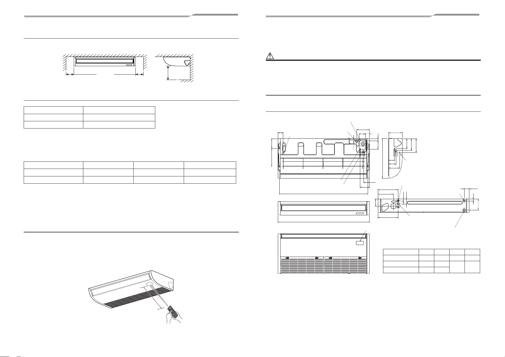
Installation space
(Unit: mm)
Reserve suffi cient space required for installation or service work.
250 or more 250 or more
500 or more
■
Ceiling height
Model MMC- Possible installed ceiling height
AP015 to AP027 Up to 4.0 m
AP036 to AP056 Up to 4.3 m
If height of ceiling exceeds 3.5 m, hot air becomes diffi cult to reach the fl oor surface, and then the change of setup
of high ceiling is necessary.
For the change method of high ceiling, refer to the application control, “Installing indoor unit on high ceiling” in this
Manual.
▼Height list of ceiling possible to be installed
Model MMC- AP015 to AP027 AP036 to AP056 SET DATA
Standard (Factory default) Up to 3.5 m Up to 3.5 m 0000
High ceiling (1) Up to 4.0 m Up to 4.3 m 0003
The lighting time of the fi lter sign (notifi cation of fi lter cleaning) on the remote controller can be changed according
to installation conditions.
When it is diffi cult to obtain satisfactory heating due to location place of the indoor unit or the structure of the room,
the detection temperature of heating can be raised.
For change the setup time, refer to the application control, “Filter sign setting” and “To secure better effect of
heating” in this Manual.
■
In case of wireless type
Decide the position which remote controller is operated and the installation place.
And then refer to the Installation Manual of the wireless remote controller kit sold separately.
(The signal of the wireless type remote controller can be received within approx. 8 m. This distance is a criterion
and varies a little according to capacity of the battery)
• To prevent malfunction, select a place where is not affected by a fl uorescent lamp or direct sunlight.
• Two wireless-type indoor units can be set in a room.
4 Installation
CAUTION
Strictly comply with the following rules to prevent damage of the indoor units and human injury.
• Do not put a heavy article on the indoor unit or let a person get on it. (Even units are packaged)
• Carry in the indoor unit as it is packaged if possible. If carrying in the indoor unit unpacked by necessity, use buffering
cloth or other material to not damage the unit.
• Carry the package by two or more persons, and do not bundle it with plastic band at positions other than specifi ed.
• To install vibration isolation material to hanging bolts, confi rm that it does not increase the unit vibration.
■
External dimensions
Upper pipe draw-out port (knockout hole)
Power supply wire take-in port
87
Left drain pipe connecting port
170320
Refrigerant pipe (Liquid side ØC)
(Hanging position)
Refrigerant pipe (Gas side ØD)
(knockout hole Ø40)
B (Hanging position)
A
Signal receiving unit mounting section
218
66109
48
98
158
235
40145
176
205
244
102
690
132
Drain pipe connecting port
192
Remote controller wire take-in port
351
270
125
353
Model MMC- A B C D
AP015, AP018 952 906 Ø6.4 Ø12.7
AP024, AP027 1269 1223
AP036 to AP056 1586 1540
Remote controller wire take-in
port (Knockout hole)
33
85
Power supply wire take-in port
(knockout hole Ø40)
Left drain pipe draw-out port
(knockout hole)
(Unit: mm)
Ø9.5 Ø15.9
87
33
191
Approx. 8 m
11-EN 12-EN
– 6 –
– 7 –
■
Installation of hanging bolt
• Consider the piping / wiring after the unit is hung to
determine the location of the indoor unit installation
and orientation.
• After the location of the indoor unit installation has
been determined, install hanging bolts.
• For the dimensions of the hanging bolt pitches, refer
to the external view and installation pattern.
Procure hanging bolts washer and nuts for installing
the indoor unit (these are not supplied).
Hanging bolt M10 or W3/8 4 pieces
Nut M10 or W3/8 8 pieces
• To fasten the hanging bracket from above and below,
twelve pieces of nuts are required.
How to use attached installation pattern
Using the pattern, positioning of the hanging bolt and
pipe hole can be performed.
The installation pattern is printed on the packing
carton. Cut it off the carton.
* As an error to some degree may generate on the
pattern size due to temperature and humidity, be
sure to confi rm the size.
Ceiling surface
Installation pattern
Wall face
Hole for drawing out pipe from top face
(Bottom View)
Additional hole required when
Drain-Up Kit is used (Ø100)
Pipe hole on top face (Ø100)
150
120
110
90
Back side of chassis
Lateral side
of chassis
Hole for drawing out pipe from back side
(Front View)
Backside cover
Pipe hole on back side (Ø100)
Top face of chassis
162
Lateral side of
chassis
108
Installation of hanging bolt
Use M10 hanging bolts (4 pcs, locally procured).
Matching to the existing structure, set pitch according
to size in the “External dimensions”.
Indoor
unit
New concrete slab
Install the bolts with insert brackets or anchor bolts.
(Blade type
bracket)
Steel fl ame structure
Use existing angles or install new support angles.
Hanging bolt
Existing concrete slab
Use a hole-in anchors, hole-in plugs, or a hole-in
bolts.
■
Installation of remote
Hanging bracket
(Slide type
bracket)
Hanging bolt
Ceiling
surface
(Pipe hanging
anchor bolt)
Support angle
50 mm
or less
Rubber
Anchor bolt
controller (Sold separately)
For installation of the remote controller, follow the
Installation Manual attached with the remote controller.
• Pull out the remote controller cord together with the
refrigerant pipe or drain pipe.
Pass the remote controller cord through upper side
of the refrigerant pipe and drain pipe.
• Do not leave the remote controller at a place
exposed to the direct sunlight and near a stove.
• Operate the remote controller, confi rm that the indoor
unit receives a signal surely, and then install it.
(Wireless type)
• Keep 1 m or more from the devices such as
television, stereo.
(Disturbance of image or noise may generate.)
(Wireless type)
■
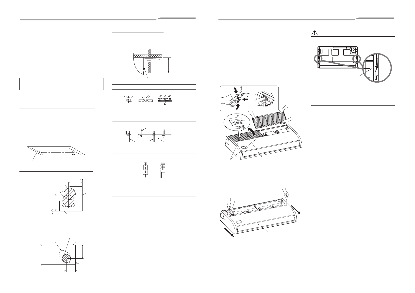
Before installation
Removal of air intake grille
1
1) Remove the screws of air intake grille fi xing
knob on a side of each fi lter.
2) Slide the air intake grille fi xing knobs (two
positions) toward the arrow direction (OPEN),
and then open the air intake grille.
3) With the air intake grille open, hold the hinge
from above and below with one hand and take
out the air intake grille with the other hand
while gently pushing it. (There are two air
intake grilles.)
Hinge
Slide
Air intake grille
fi xing knob
Removal of side panel
2
After removing the side panel fi xing screws
(1 each at right and left), slide the side panel
forward and then remove it.
Side panel
Side panel fi xing screw
Slide forward.
Air intake grille
Louver
CAUTION
Cushion
Cushions are inserted between the side panel and
hanging hook for transportation.
(In the two places shown above)
Remove them before installation.
13-EN 14-EN
 Loading...