

Page 1

A90-0132
Modular Multi System
Service Manual
Air Conditioner - Multi Split Type System
HFC R407C
Page 2

2
Page 3

Contents
Introduction ......................................................................................................................... 5
Summary.............................................................................................................................8
Outline of MMS (Modular Multi System)............................................................................ 10
Parts Specifications........................................................................................................... 12
Construction Views – Outdoor Units ................................................................................. 21
Construction Views – Indoor Units .................................................................................... 22
Wiring Diagrams................................................................................................................ 31
Refrigerant Piping Systematic Drawings ........................................................................... 44
Combined Refrigerant Piping Systematic Drawings.......................................................... 49
Refrigerant Cycle Schematic – Indoor Units ..................................................................... 53
1
2
3
4
5
6
7
8
9
10
Outline of Control ..............................................................................................................54
Self Diagnostic Display Information...................................................................................67
Control Circuit Configuration ............................................................................................. 71
Troubleshooting ................................................................................................................ 76
Back-up Operation ..........................................................................................................122
Forced Function of Oil Level Detection ........................................................................... 126
Refrigerant Pipe Installation ............................................................................................ 127
Trial Operation ................................................................................................................ 132
Replacing the Compressor.............................................................................................. 145
Exploded Views and Service Parts .................................................................................156
11
12
13
14
15
16
17
18
19
20
3
Page 4

4
Page 5

Introduction
Precautions
Please read these instructions carefully before starting the installation.
This equipment should only be installed by suitably trained operatives.
In all cases ensure safe working practice: Observe precautions for persons in the vicinity of the works.
Ensure that all local, national and international regulations are satisfied.
Check that the electrical specifications of the unit meet the requirements of the site.
Carefully unpack the equipment, check for damage or shortages. Please report any damage immediately.
These units comply with EU Directives:
73/23/EEC (Low Voltage Directive), 89/336/EEC (Electromagnetic Compatibility) and 97/23/EC (Pressure Equipment
Directive). Accordingly, they are designated for use in commercial and industrial environments*.
Avoid installation in the following locations:
Where there is danger of flammable gas leakages.
Where there are high concentrations of oil.
Where the atmosphere contains an excess of salt (as in coastal areas). The air conditioner is prone to failure when
used under this condition unless special maintenance is provided.
1
Where the airflow from the outdoor unit may cause annoyance.
Where the operating noise of the outdoor unit may cause annoyance.
Where the foundation is not strong enough to fully withstand the weight of the outdoor unit.
Where the water drainage may cause a nuisance or a hazard when frozen.
Where strong winds may blow against the air outlet of the outdoor unit.
Precautions for R407C outdoor units
R407C outdoor units use synthetic oils which are extremely hygroscopic. Therefore ensure that the refrigerant system
is NEVER exposed to air or any form of moisture.
Mineral oils are unsuitable for use in these units and may lead to premature system failure.
Use only equipment which is suitable for use with R407C. Never use equipment which has been used with R22.
R407C should only be charged from the service cylinder in the liquid phase. It is advisable to use a gauge manifold set
equipped with a liquid sight glass fitted in the centre (entry) port.
* 97/23/EC Pressure Equipment Directive information
Conformity assessment procedure: Module D1
Pressure equipment:
Compressor, category II, Module A1
Accumulator, category I
Liquid receiver, category II
High pressure switch, category II, Module A1
Notified body for inspection and quality assurance systems: BSI, Maylands Avenue, Hemel Hempstead, WP2 4SQ, UK.
5
Page 6
Introduction
Precautions
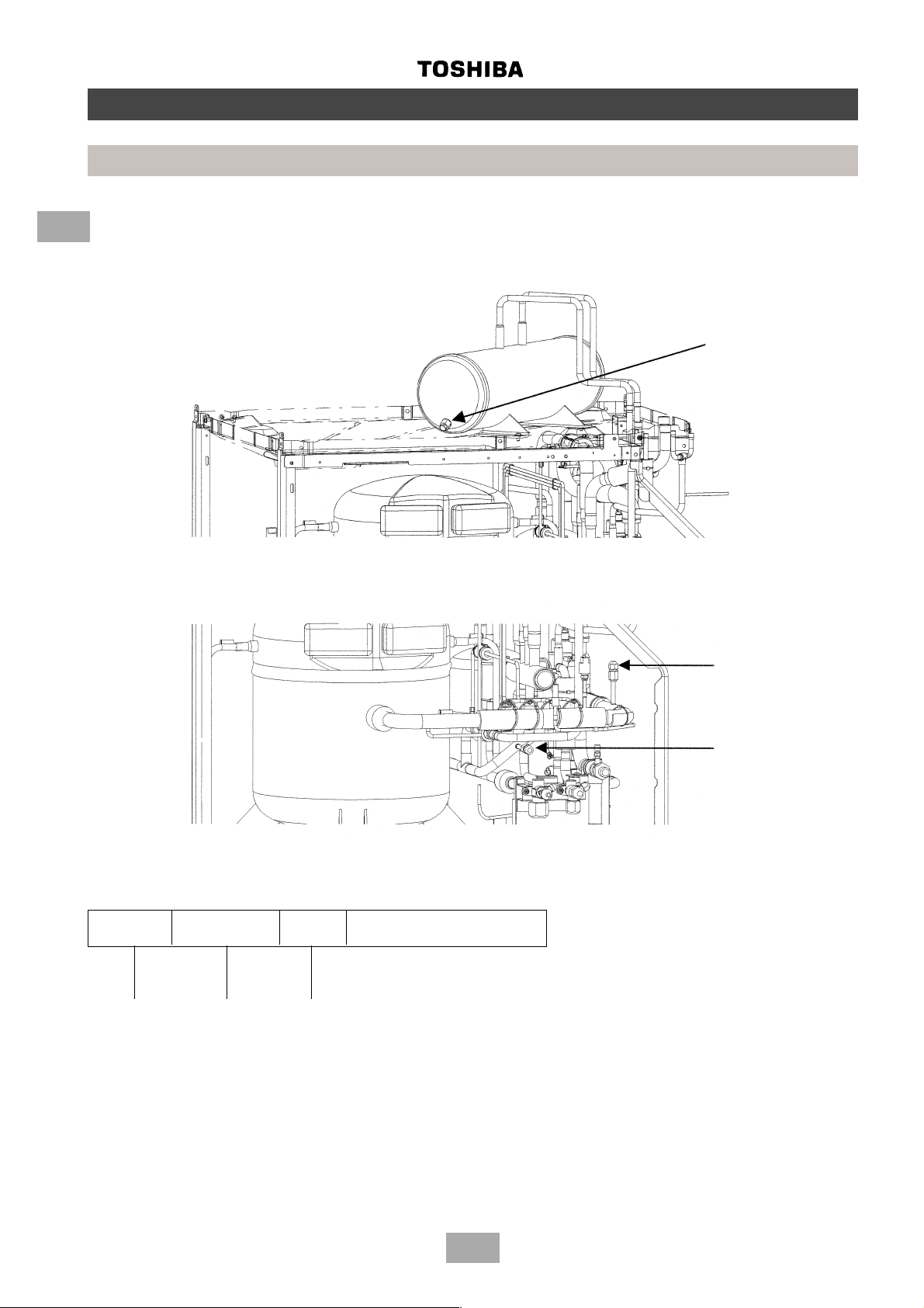
Precautions for R-407C outdoor units
1
Liquid receiver fusible plug
In the event of the system being subjected to abnormal conditions it is protected by a fusible plug, positioned on the liquid
receiver, within the outdoor unit. It is rated to fail at 70°C.
Position of
fusible plug
System pressure measurement
To measure the system’s high and low pressures, connect a gauge manifold to the corresponding access port as indicated
below.
Low pressure
access port
High pressure
access port
Explanation of Toshiba serial number
A serial label is attached to all Toshiba air conditioning units. Located on the label is an 8-digit number, which represents the
month, year and batch number of the manufactured unit. A breakdown of the 8-digit number is defined below.
24480001
}
Year of
manufacture
2001 = 1
2002 = 2
2003 = 3
Month of
manufacture
41 = Jan.
42 = Feb.
43 = Mar.
44 = Apr.
45 = May
46 = Jun.
47 = Jul.
48 = Aug.
49 = Sep.
50 = Oct.
51 = Nov.
52 = Dec.
Site of
manufacture
8 = Plymouth
Model batch serial number
6
Page 7
Introduction
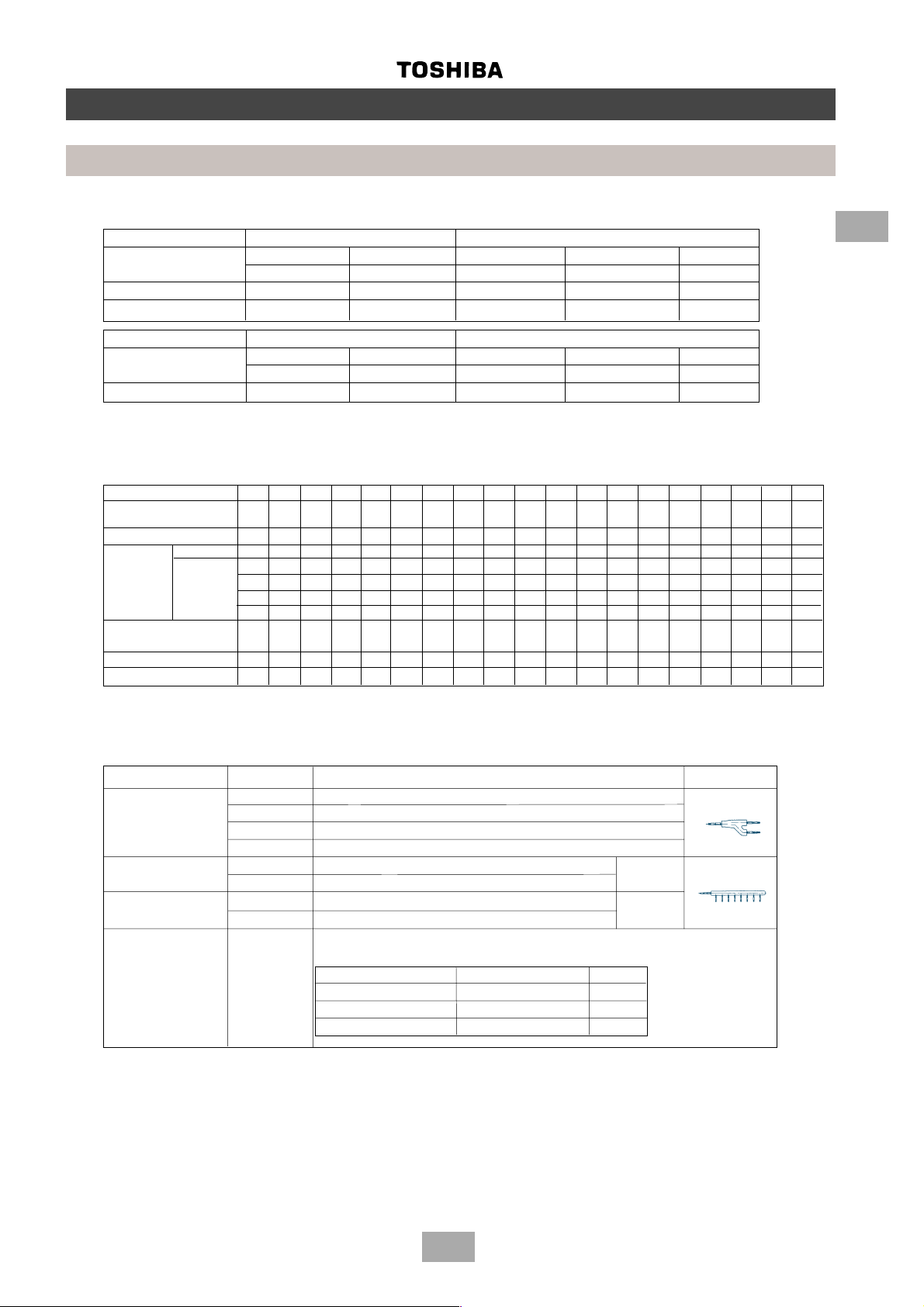
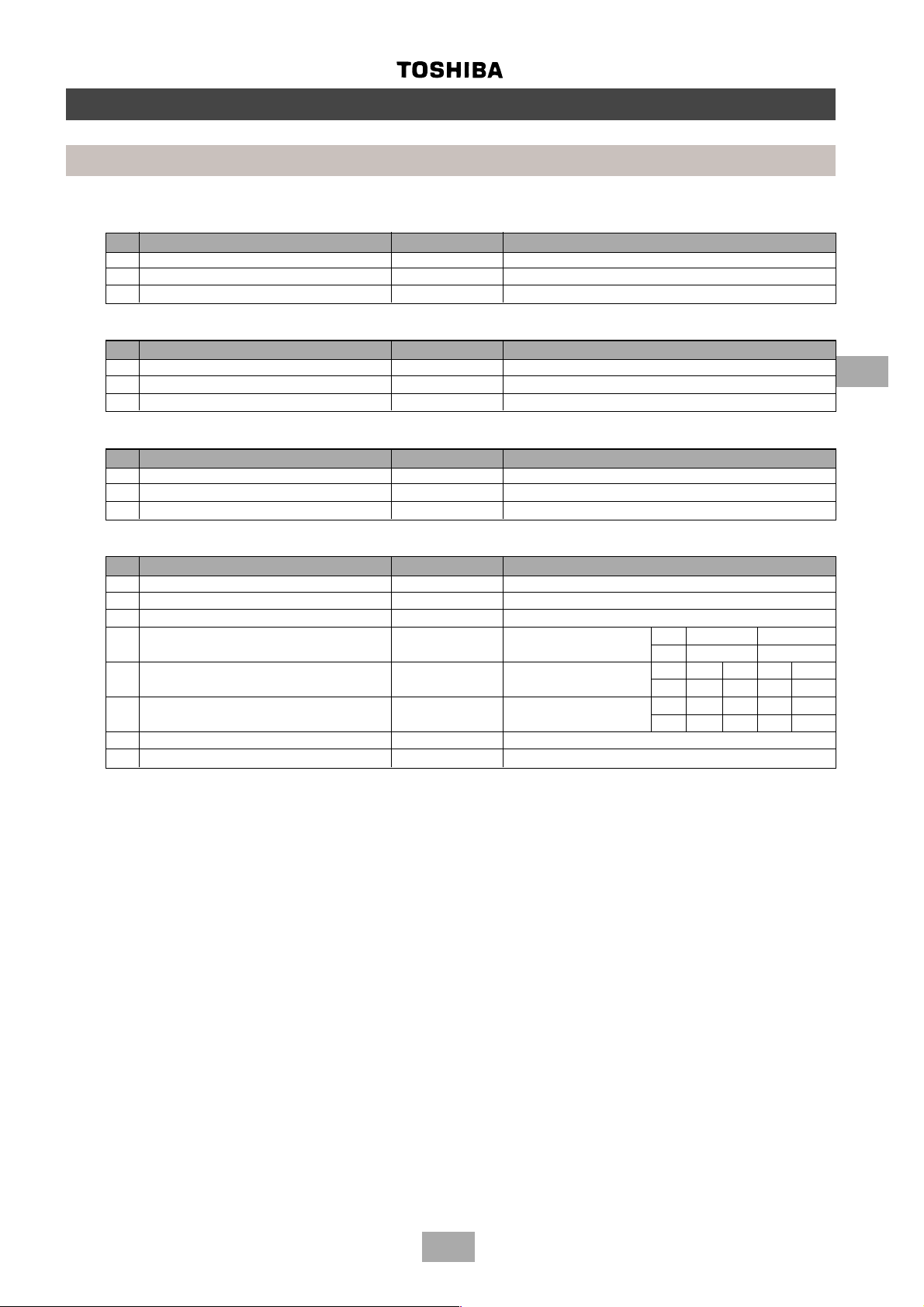
Components
1. Outdoor unit
Corresponding HP Inverter unit Fixed-speed unit
8 HP 10 HP 6 HP 8 HP 10 HP
Model name MM-A0224HT MM-A0280HT MM-A0160HX MM-A0224HX MM-A0280HX
Cooling capacity (kW) 22.4 28.0 16.0 22.4 28.0
Heating capacity (kW) 25.0 31.5 18.0 25.0 31.5
Corresponding HP Inverter unit Fixed-speed unit
8 HP 10 HP 6 HP 8 HP 10 HP
Model name MM-A0224CT MM-A0280CT MM-A0160CX MM-A0224CX MM-A0280CX
Cooling capacity (kW) 22.4 28.0 16.0 22.4 28.0
2. Outdoor units (combination of outdoor units)
Corresponding HP 8HP 10HP 14HP 16HP 18HP 20HP 22HP 24HP 26HP 28HP 30HP 32HP 34HP 36HP 38HP 40HP 42HP 44HP 46HP
Combined model
MM-A-HT/MM-A-CT 0224 0280 0384 0440 0504 0560 0608 0672 0728 0784 0840 0896 0952 1008 1064 1120 1176 1232 1288
Cooling capacity (kW) 22.4 28.0 38.4 44.8 50.4 56.0 60.8 67.2 72.8 78.4 84.0 89.6 95.2 100.8 106.4 112.0 117.6 123.2 128.8
Combined Fixed-speed - - 6HP 8HP 8HP 10HP 8HP 8HP 8HP 10HP 10HP 8HP 8HP 10HP 10HP 10HP 8HP 10HP 10HP
outdoor units unit - -----6HP8HP8HP8HP10HP 8HP 8HP 8HP 10HP 10HP 8HP 8HP 10HP
No. of connectable
indoor units 13 16 16 18 18 20 22 2 4 26 28 30 32 34 36 38 40 40 40 40
Min. HP connected 4 57891011121314151617181920212223
Max. HP connected 10.8 13.5 18.9 21.6 24.3 27 29.7 32.4 35.1 37.8 40.5 43.2 45.9 48.6 51.3 54 56.7 59.4 62.1
Inverter unit 8HP 10HP 8HP 8HP 10HP 10HP 8HP 8HP 10HP 10HP 10HP 8HP 10HP 10HP 10HP 10HP 10HP 10HP 10HP
-----------8HP8HP8HP8HP10HP 8HP 8HP 8HP
----------------8HP8HP8HP
1
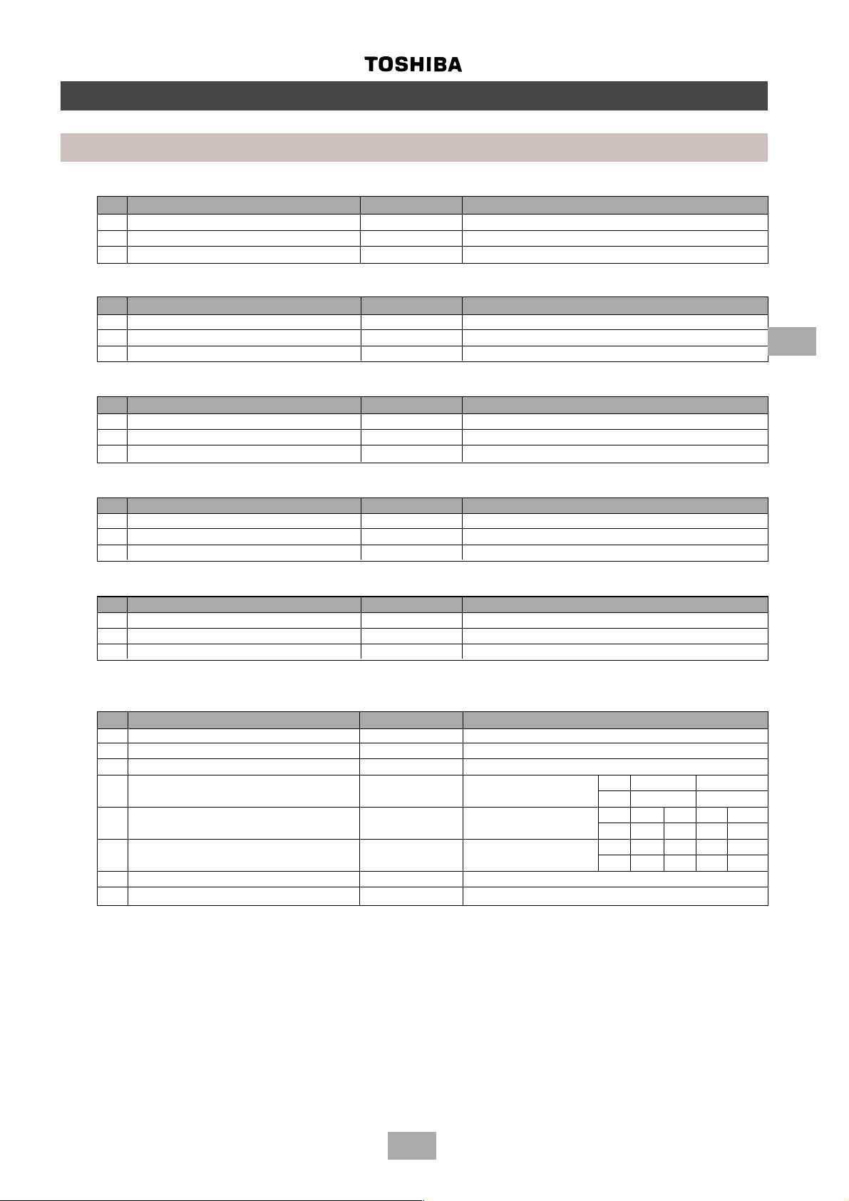
3. Branching joints/headers
Model name Usage Appearance
Y -shape branching joint RBM-Y018-SK Indoor unit capacity code (*1): Total < 6.4
RBM-Y037-SK Indoor unit capacity code (*1): 6.4 = Total < 13.2 (*2)
RBM-Y071-SK Indoor unit capacity code (*1): 13.2 = Tot al < 25.2 (*2)
RBM-Y129-SK Indoor unit capacity code (*1): 25.2 = Total (*2)
4-branching header (*3) RBM-H4037-SK Indoor unit capacity code (*1): Total < 6.4 Max. 4
RBM-H4071-SK Indoor unit capacity code (*1): 6.4 = Total < 13.2 branches
8-branching header (*3) RBM-H8037-SK Indoor unit capacity code (*1): Total < 6.4 Max. 8
RBM-H8071-SK Indoor unit capacity code (*1): 6.4 = Total < 13.2 branches
T-shape branching joint 1 set of 3 types of T-shape joint pipes as described below .
(For connection of The required quantity is arranged and they are combined at the site.
outdoor unit) RBM-T129-SK
Connecting pipe Corresponding dia. (mm) Quantity
Balancing pipe 9.52 1
Piping at liquid side 12.7 to 22.2 1
Piping at gas side 22.2 to 54.1 1
(*1) Code is determined according to the capacity code of the Indoor units connected.
(*2) If the total capacity code value of Indoor units exceeds that of Outdoor units, apply the capacity code of Outdoor units.
(*3) When using a branch header, Indoor units with a maximum of 6.0 capacity code in total can be connected to each
branch.
NOTE: If the length of the gas pipe exceeds 30m from the 1st branching to an Indoor unit, increase the gas pipe size by
1 size, i.e. MM-U140 = Gas Ø22.2, Liquid Ø9.5
7
Page 8

Summary
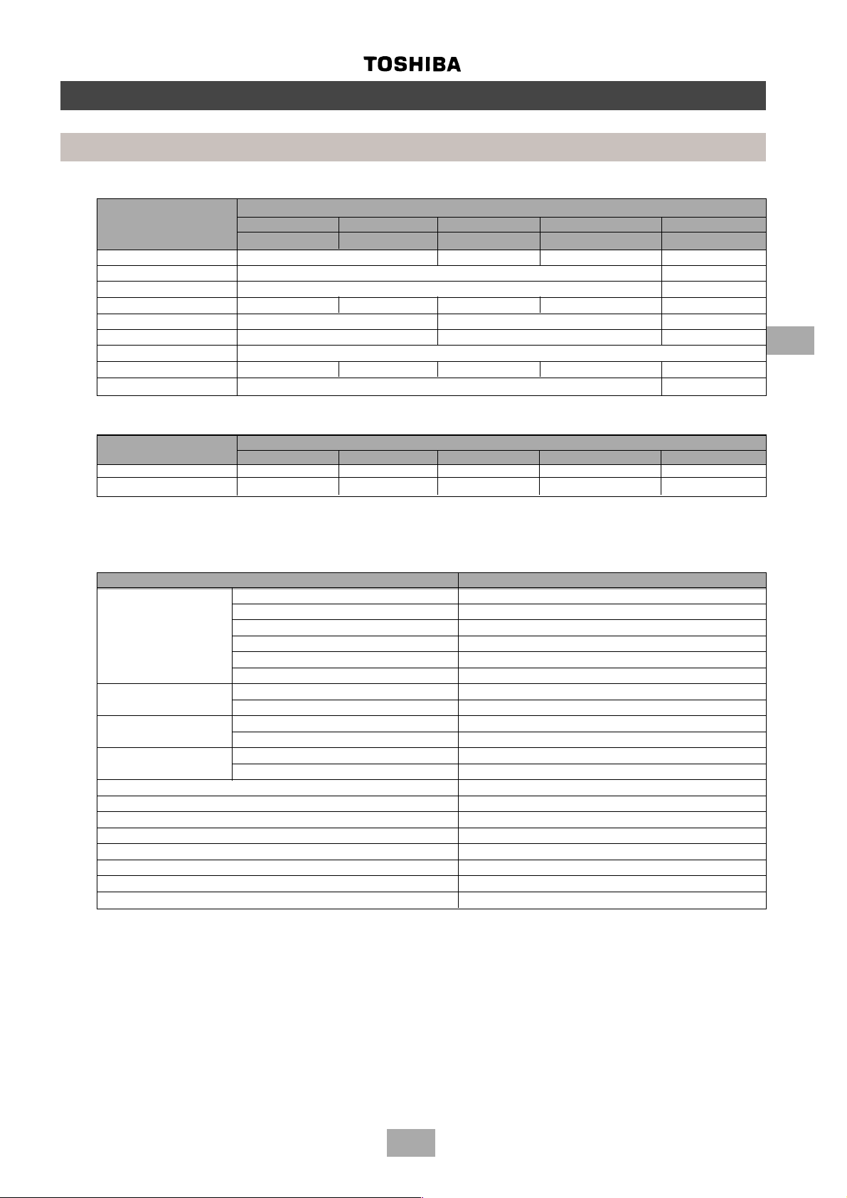
Operating conditions
• The units referred to within this manual conform with the protection requirements of Directives 89/336/EEC
Electromagnetic Compatibility and 73/23/EEC Low voltage.
• Operating conditions of the unit are as follows:
2
Note 1: Cooling capacity is rated at the following temperature conditions:
Indoor air inlet temperature 27°C DB, 19°C WB.
Outdoor air inlet temperature 35°C DB.
Note 2: Heating capacity is rated at the following temperature conditions:
Indoor air inlet temperature 20°C DB.
Outdoor air inlet temperature 7°C DB, 6°C WB.
Note 3: For details about the Outdoor unit, Indoor units or Remote Controller installation refer to the relevant literature, i.e.
Installation Instructions supplied with the units.
Note 4: Operatives handling refrigerants must be suitably qualified in accordance with local and national codes of practice
and statutory requirements.
Note 5: Legislation may regulate the removal of waste refrigerant from the systems. We advise awareness of any
regulations and duty of care. Waste refrigerant must NEVER be discharged to atmosphere.
Note 6: Electrical work should be in accordance with all relevant codes of practice and should be carried out by suitably
qualified personnel.
Outdoor temperature -5 ~ 43°C Cooling
-15 ~ 21°C Heating
Room temperature 18 ~ 32°C Cooling
15 ~ 29°C Heating
Room humidity <80% Cooling
Note 7: Metric/Imperial pipe conversion.
Diameter (mm) 6.4 9.5 12.7 15.9 19.0 2.0 28.6 34.9 41.3 54.1
Nominal diameter (inch) 1/4 3/8 1/2 5/8 3/4 7/8 1-1/8 1-3/8 1-5/8 2-1/8
Note 8: Within this manual:
ODU = Outdoor Unit IDU = Indoor Unit
R/C = Remote Controller D.O.L. = Direct On-Line compressor
INV = Inverter ODU FIX = Fixed-speed ODU
DB = Dry Bulb WB = Wet Bulb
Mg-Sw = Magnetic Contactor IOL = Inner Overload Relay
OCR = Over Current Relay IGBT = Inverter Gate Bi-Polar Transistor
Note 9: MPaG
1.0 MPaG = 10.2 kgf/cm
⇒ kgf/cm
2
G conversion multiplier
2
G
8
Page 9
1. Model name
OUTDOOR
MM-A0280HT
Summary
Operating conditions
2
INDOOR
A – Outdoor 0280 – 28 kW (10 HP) C - Cooling T – Inverter
Modular Multi
MM-TU056
B - Built-In Duct Type
C (CR) - Ceiling Type (IR Remote) 028 – 2.8 kW (1 HP)
Modular Multi
K (KR) - High Wall Type (IR Remote) 042 – 4.2 kW (1.5 HP)
N - Chassis Type 056 – 5.6 kW (2 HP)
S (SR) - Low Wall Type (IR Remote) 080 – 8.0 kW (3 HP)
SB - Built-In Slim Duct Type 112 – 12.2 kW (4 HP)
TU - 2-way Cassette Type 140 – 14.0 kW (5 HP)
U - 4-way Cassette Type
0224 – 22.4 kW (8 HP H - Heating X – Fixed-speed
0160 – 16.0 kW (6 HP)
2. Range of combined units
No. of combined units : 1 to 5 units
Capacity range : Equivalent to 38.4 kW type (14HP) to 128.8 kW (46HP)
3. Restriction for combination units
(1) The Inverter Unit should have the maximum capacity among all units in that combination.
(2) The 16.0 kW (6HP) fixed-speed unit is available only with the combination of 38.4 kW (14HP) and 60.8 kW
(22HP). (It cannot be used for any other combination.)
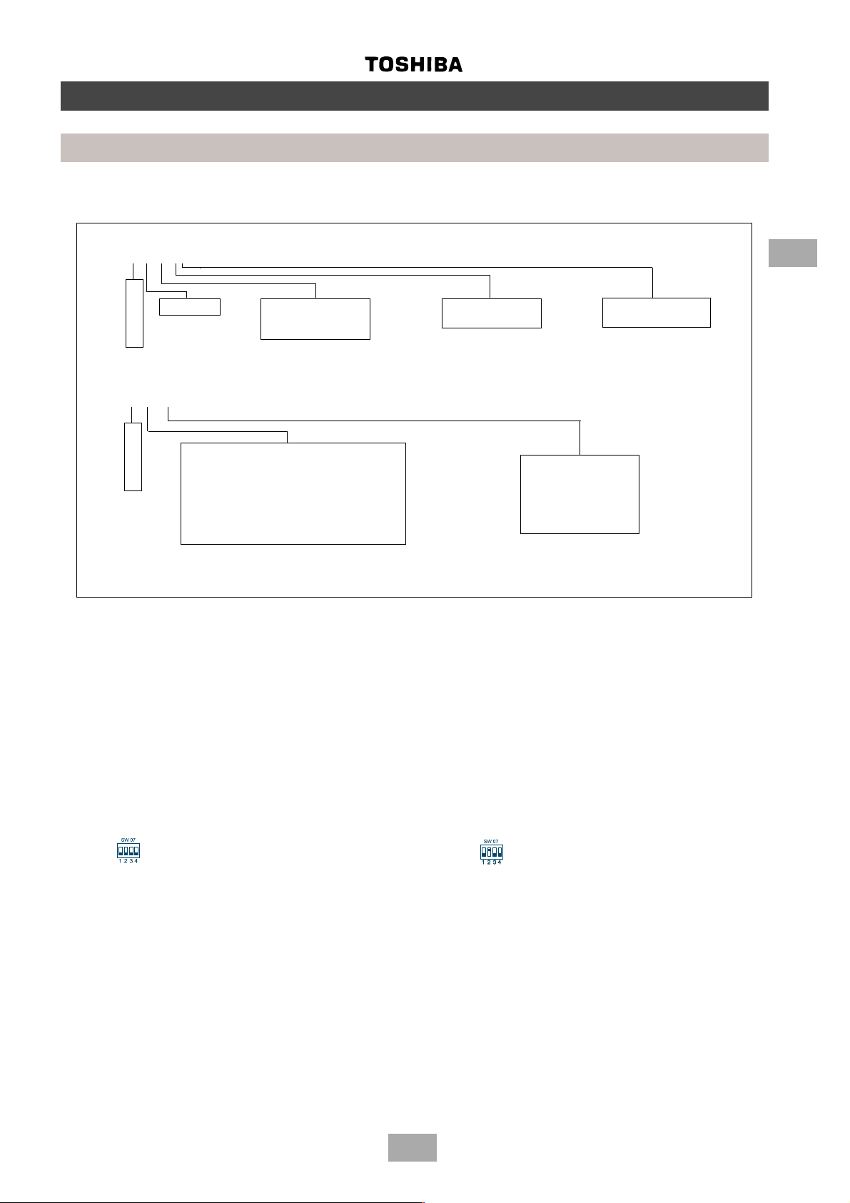
4. Mode priority
This Outdoor Unit is set to operate with the Heating mode taking precedence. This precedence can be switched
between Heat and Cool mode using the DIP switch 07 on the Outdoor Unit Interface PCB (MCC-1343-01) as follows:
ON
OFF
Heat priority (factory set) Cool priority
ON
OFF
9
Page 10
3
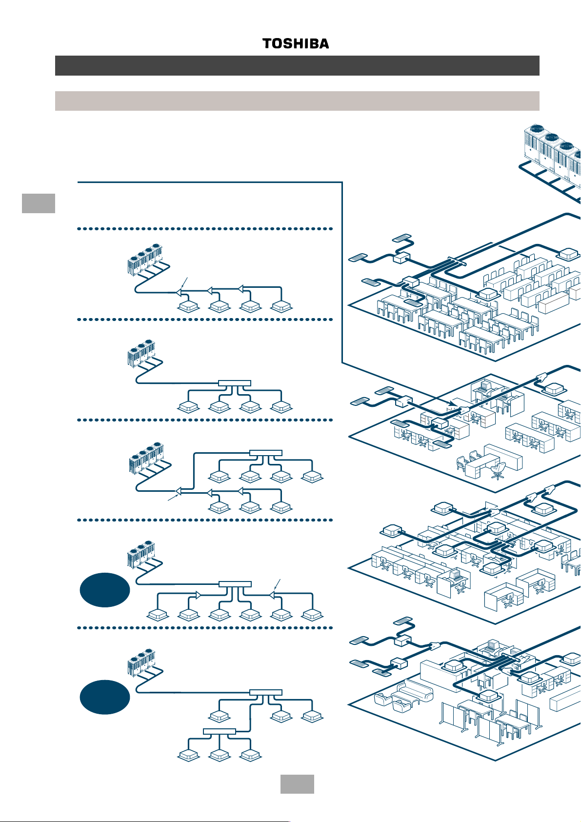
Outline of MMS (Modular Multi System)
• Branching
Combination of line and header branching is highly flexible. This allows for the
shortest design route possible, thereby saving on installation time and cost.
Line/header branching after header branching is only available with Toshiba’s
Multi Modular System.
Line branching
Outdoor unit
Branching joint
Indoor unit
Header branching
Outdoor unit
Indoor unit
Line and header branching
Outdoor unit
Branching joint
Indoor unit
Line branching after header branching
Outdoor unit
MMS
ONLY
Branching
header
Header
Header
Branching joint
8F
7F
2F
Indoor unit
Outdoor unit
MMS
ONLY
Header
1F
Header
Indoor unit
10
Page 11
Outline of MMS (Modular Multi System)
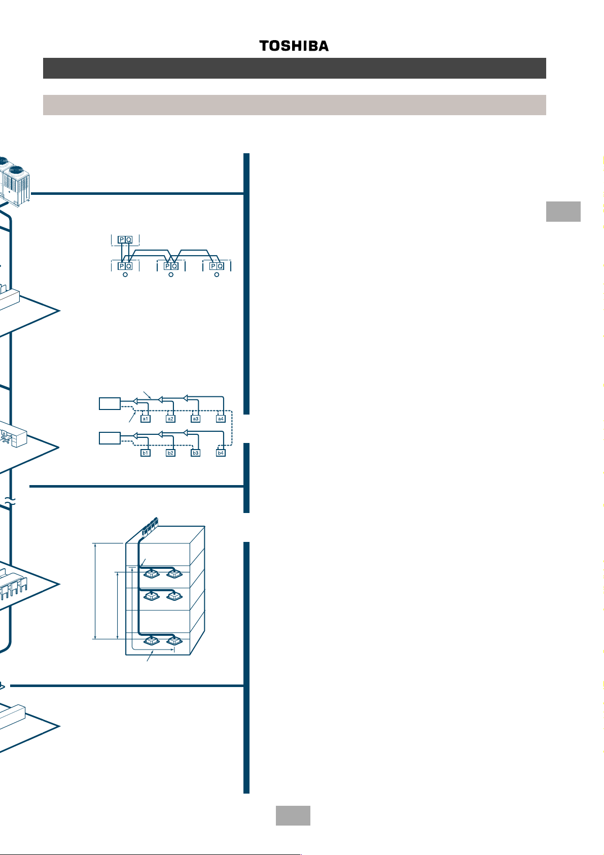
• Non-polarized control wiring between outdoor and
indoor units
Outdoor unit
Indoor unit
• Compact design
The design of the Toshiba MMS outdoor unit allows for
easy unit maneuvering into any standard lift. Its size also
allows it to be easily installed in limited spaces.
• Largest system capacity
Toshiba’s Multi Modular System can be combined up to
128.8 kW (46 HP).
3
• Wiring diagnosis system
[Example of wiring diagnosis]
Use the switches on the microcomputer PCB of the
outdoor unit.
• Detects wiring to the indoor unit b4 which should
not be in system A.
• b4 is missing in system B.
Piping
Outdoor
Circuit A
Circuit B
unit
Piping
Outdoor
unit
Allowable pipe length:
100 m real length
Outdoor unit
unit and outdoor unit: 50 m
Height difference between indoor
unit and outdoor unit: 30 m
Height difference between indoor
(Equivalent to 125 m)
1st branching
section
Indoor unit
• Advanced bus communication system
Wiring between indoor and outdoor unit is a simple 2wire system.
Communication address is also automatically configured.
A default test mode operation is available.
• Self diagnostic system
Comprehensive troubleshooting code enables quick
identification of problems arising.
• High lift design
Real pipe length of 100m (equivalent length 125m) and
vertical lift of 50m is made possible with Toshiba’s Multi
Modular System.
Vertical lift between indoor units of 30m is the highest in
the market.
This allows for greater flexibility in the location of the
system.
• Multiple indoor units
Indoor units with different capacities and configurations
can be combined up to 135% of the outdoor unit capacity.
A maximum of 40 indoor units can be combined with the
46 HP outdoor module.
• Intelligent control
Toshiba’s MMS intelligent controls and modulating
valves deliver the required capacity, according to the
load variation from 50% to 100%.
The intelligent controls and modulating valves limit or
increase the cooling/heating capacity dynamically so
humidity and temperature are kept in the comfort zone.
From 1st branching to the
farthest indoor unit: 50 m
11
Page 12
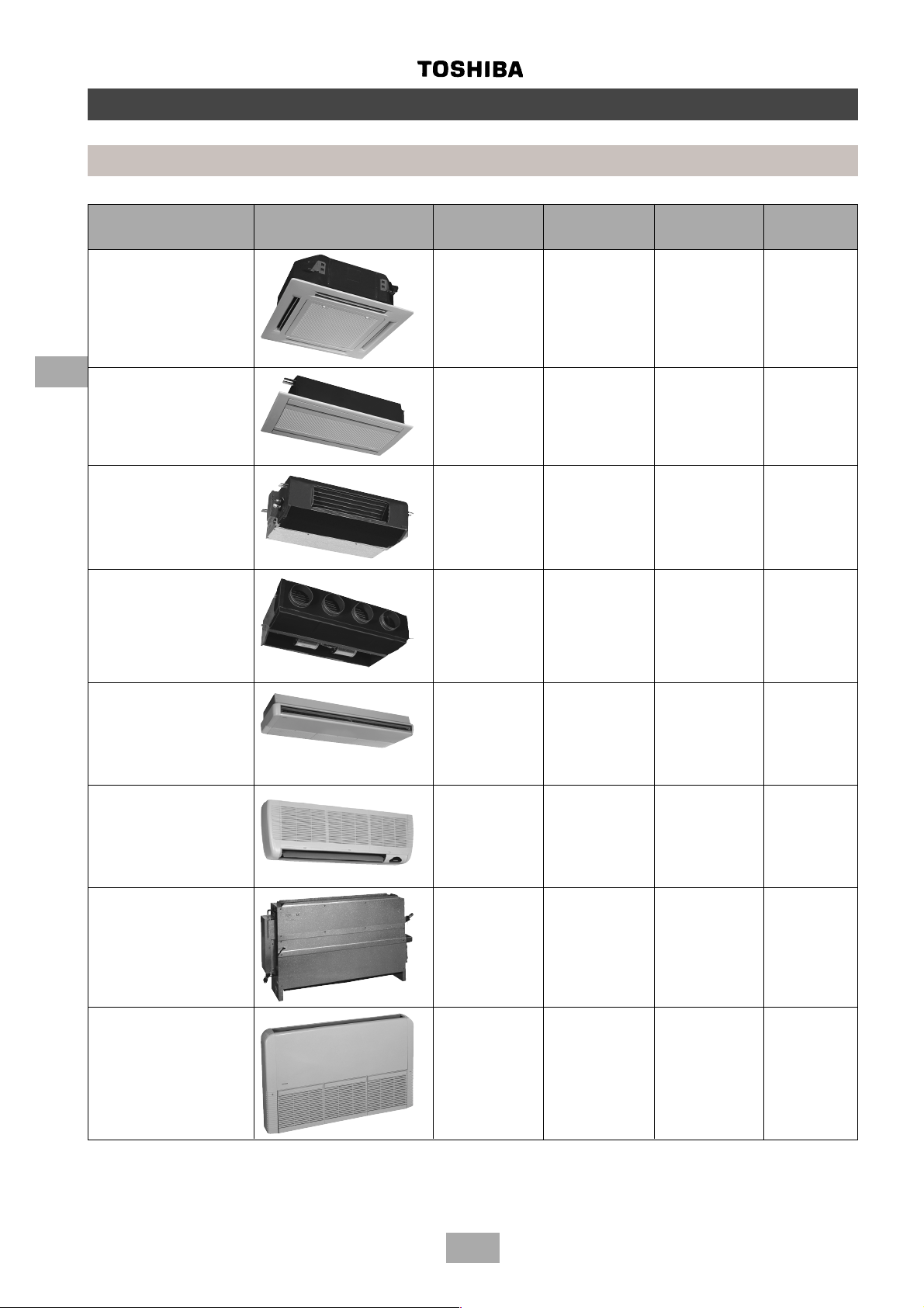
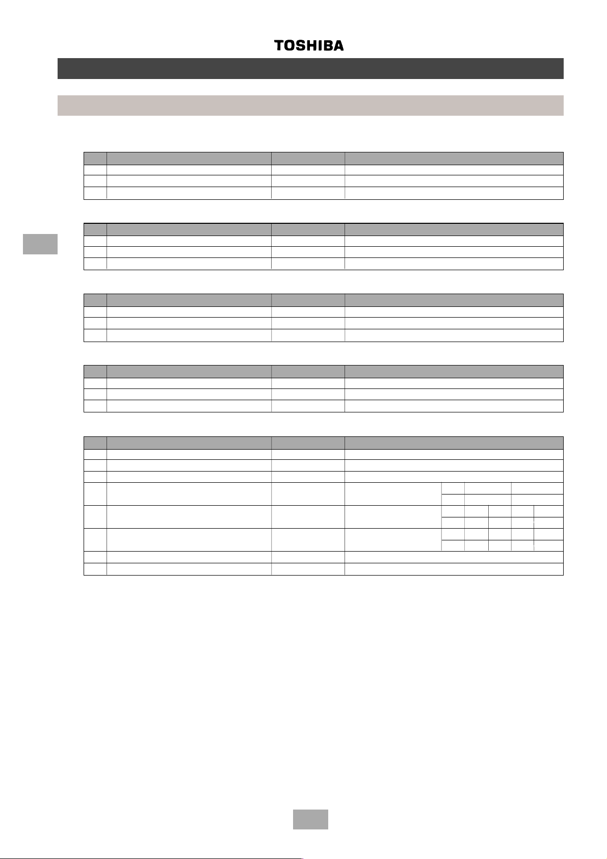
Parts specifications
Indoor units
Type Appearance Model name Capacity code Cooling Heating
capacity (kW) capacity (kW)
4-Way Cassette MM-U056 2 5.6 6.4
Type ‘U’ MM-U080 3 8.0 9.6
MM-U112 4 11.2 12.8
MM-U140 5 14.0 15.8
4
2-Way Cassette MM-TU028 1 2.8 3.2
Type ‘TU’ MM-TU042 1.5 4.2 4.8
MM-TU056 2 5.6 6.4
Built-In Slim Duct MM-SB028 1 2.8 3.2
Type ‘SB’
Built-In Duct MM-B056 2 5.6 6.4
Type ‘B’ MM-B080 3 8.0 9.6
MM-B112 4 11.2 12.8
MM-B140 5 14.0 15.8
Ceiling MM-C/CR042 1.5 4.2 4.8
Type ‘C’ MM-C/CR056 2 5.6 6.4
MM-C/CR080 3 8.0 9.6
MM-C/CR112 4 11.2 12.8
MM-C/CR140 5 14.0 15.8
High Wall MM-K/KR042 1.5 4.2 4.8
Type ‘K’ MM-K/KR056 2 5.6 6.4
MM-K/KR080 3 8.0 9.6
Chassis MM-N028 1 2.8 3.2
Type ‘N’ MM-N042 1.5 4.2 4.8
MM-N056 2 5.6 6.4
MM-N080 3 8.0 9.6
Low Wall MM-S/SR056 2 5.6 6.4
Type ‘S’ MM-S/SR080 3 8.0 9.6
12
Page 13
Parts specifications
Outdoor units
COMPRESSOR MODEL
MM-A0280HT MM-A0224HT MM-A0280HX MM-A0224HX MM-A0160HX
MM-A0280CT MM-A0224CT MM-A0280CX MM-A0224CX MM-A0160CX
Model name MG1450CW-21B YG1800CW-B1 YG1700CW-B1 YG890C-B1
Motor type 3-phase induction motor
Power supply 380-415 V, 3 ph, 50 Hz
Output (kW) 7.5 7.5 7.5 6.0 4.1
Pole (P) 2/2 (INV ./Fixed) 2/2 (Fixed/Fixed) 2
Coil resistance (Ω) 1.18/2.25 (INV./Fixed) 2.25/2.25 (Fixed/Fixed ) 2.250
Comp. oil name NISSEKI RB74AF VG 74
Amount of oil (ml) 7500 7500 7500 7500 2000
Inner overload relay Opens: 115±5°C Closes: 93±10°C
4-WA Y V ALVE MODEL
MM-A0280HT MM-A0224HT MM-A0280HX MM-A0224HX MM-A0160HX
Model name CHV-0712 CHV-0712 CHV-0712 CHV-0712 CHV-0401
Coil specification AC240V AC240V AC240V AC240V AC240V
4
MM-A0280HT, MM-A0224HT, MM-A0280HX, MM-A0224HX, MM-A0160HX
MM-A0280CT, MM-A0224CT, MM-A0280CX, MM-A0224CX, MM-A0160CX
PARTS NAME SPECIFICATION
Fan motor Model name STF-200-350A
Motor type 1-phase induction motor
Power supply AC 220 – 240 V. 1 phase, 50 Hz
Output (W) 400
Current (A) 4.81-5.89
Pole (P) 6
High pressure switch Model name INV = ACB-JB128 FIX = ACB-JA64
Operating pressure (mPa) Operation: 3.2 Reset: 2.55
High pressure sensor Model name 150NH4-H
Operating conditions (mPa) 0-3.33
Low pressure sensor Model name 150NH4-L
Operating conditions (mPa) 0-0.98
Compressor case heater (fixed-speed only) AC 240 V – 74 W
Accumulator case heater AC 240 V – 29 W
Discharge temperature sensor 18.1 kΩ at 50 °C – 3.35 kΩ at 100 °C
Suction temperature sensor 34.6 kΩ at 0 °C – 10.0 kΩ at 25 °C – 3.4 kΩ at 50 °C
Pulse modulating valve (heat pump unit only) L12A-03, DC 12 V
Pulse modulating valve (for cooling bypass) A12A-15, DC 12 V
2-way valve NEV-603DXF, coil 240 V
2-way valve NEV-202DXF, coil 240 V
13
Page 14
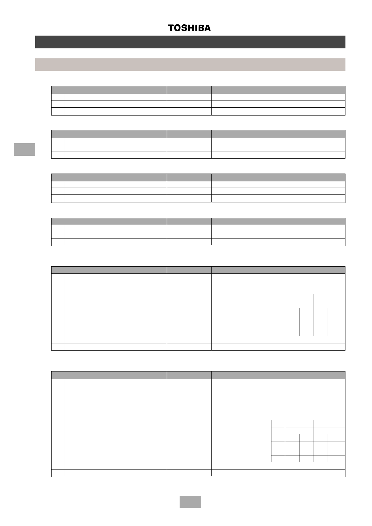
Built-In Duct: MM-B140
No. PARTS NAME TYPE SPECIFICATIONS
1 Fan motor STF-200-140-4F Output (rated) 140 W, 4 pole, 200 V, 1 phase, 50 Hz
2 Running capacitor – Fan motor EAG40M106UF AC 400 V , 10 µF
3 Pulse motor valve EDM-B60YPTF-7B-A Capacity: 60
Built-In Duct: MM-B112
No. PARTS NAME TYPE SPECIFICATIONS
1 Fan motor STF-200-120-4B Output (rated) 120 W, 4 pole, 200 V, 1 phase, 50 Hz
4
2 Running capacitor – Fan motor EAG40M505UF AC 400 V, 5 µF
3 Pulse motor valve EDM-B40YPTR-7B-A Capacity: 40
Built-In Duct: MM-B080
No. PARTS NAME TYPE SPECIFICATIONS
1 Fan motor STF-200-100-4B Output (rated) 100 W, 4 pole, 200 V, 1 phase, 50 Hz
2 Running capacitor – Fan motor EAG40M505UF AC 400 V, 5 µF
3 Pulse motor valve EDM-B40YPTR-7B-A Capacity: 40
Built-In Duct: MM-B056
No. PARTS NAME TYPE SPECIFICATIONS
1 Fan motor STF-230-60-4A Output (rated) 60 W, 4 pole, 230 V, 1 phase, 50 Hz
2 Running capacitor – Fan motor EEP2G405HQA114 AC 400 V, 4 µF
3 Pulse motor valve EDM-B40YPTR-7B-A Capacity: 40
Parts specifications
Indoor units
Built-In Duct: MM-B140, MM-B112, MM-B080, M-B056
No. PARTS NAME TYPE SPECIFICATIONS
4 Transformer TT-03-1 DC 16.3 V – 0.5 A / AC 11.6 V – 0.15 A
5 Pulse motor EDM-MD12TF-3 DC 12 V
6 Pressure sensor 150/100NH6-D Power voltage DC 12 V
7 Sensor for room temperature T A Maximum input: °C 25 50
38 mA at 25 °C kΩ 10 3.45
8 Sensor for heat exchanger Tc1 Maximum input: °C -12 0 25 50
34 mA at 25 °C kΩ 62.3 32.8 10 3.6
9 Sensor for heat exchanger Tc2 Maximum input: °C 0 25 50
26 mA at 25 °C kΩ 34.6 10 3.4
10 Control PCB CM**C02 AC 220 – 240 V
11 Power PCB P**RC01 AC 220 – 240 V
Built-In Duct: MM-SB028
No. PARTS NAME TYPE SPECIFICATIONS
1 Fan motor SMF-230-34-4J Output (rated) 34 W, 4 pole, 220 V , 1 phase, 50 Hz
2 Running capacitor – Fan motor EEP2H105HQA105 AC 400 V , 1 µF
3 Pulse motor valve EDM-B25YPTF-7B-A Capacity: 25
4 Transformer TT-03-1 DC 16.3 V – 0.5 A / AC 11.6 V – 0.15 A
5 Pulse motor EDM-MD12TF-3 DC 12 V
6 Pressure sensor 150/100NH6-D Power voltage DC 12 V
7 Sensor for room temperature T A Maximum input: °C 25 50
38 mA at 25 °C kΩ 10 3.45
8 Sensor for heat exchanger Tc1 Maximum input: °C -12 0 25 50
34 mA at 25 °C kΩ 62.3 32.8 10 3.6
9 Sensor for heat exchanger Tc2 Maximum input: °C 0 25 50
26 mA at 25 °C kΩ 34.6 10 3.4
10 Control PCB CM**C02 AC 220 – 240 V
11 Power PCB P**RC01 AC 220 – 240 V
14
Page 15
Parts Specifications
Indoor units
Ceiling: MM-C140, MM-CR140
No. PARTS NAME TIPO SPECIFICATIONS
1 Fan motor SMF-230-75-4B Output (rated) 75 W, 4 pole, 230 V , 1 phase, 50 Hz
2 Running capacitor – Fan motor EEP2G405HQA114 AC 400 V , 4 µF
3 Pulse motor valve EDM-B60YPTF-7B-A Capacity: 60
Ceiling: MM-C112, MM-CR112
No. PARTS NAME TYPE SPECIFICATIONS
1 Fan motor SMF-230-75-4U Output (rated) 75 W, 4 pole, 230 V, 1 phase, 50 Hz
2 Running capacitor – Fan motor EVM45M305UF AC 450 V, 3 µF
3 Pulse motor valve EDM-B40YPTR-7B-A Capacity: 40
Ceiling: MM-C080, MM-CR080
No. PARTS NAME TYPE SPECIFICATIONS
1 Fan motor SMF-230-34-4D Output (rated) 34 W, 4 pole, 230 V, 1 phase, 50 Hz
2 Running capacitor – Fan motor EEP2W255HQA113 AC 450 V, 2,5 µF
3 Pulse motor valve EDM-B40YPTR-7B-A Capacity: 40
Ceiling: MM-C056, MM-CR056
No. PARTS NAME TYPE SPECIFICATIONS
1 Fan motor SMF-230-34-4D Output (rated) 34 W, 4 pole, 230 V, 1 phase, 50 Hz
2 Running capacitor – Fan motor EEP2W255HQA113 AC 450 V, 2,5 µF
3 Pulse motor valve EDM-B40YPTR-7B-A Capacity: 40
4
Ceiling: MM-C042, MM-CR042
No. PARTS NAME TYPE SPECIFICATIONS
1 Fan motor MMF-230-34-4H Output (rated) 34 W, 4 pole, 230 V, 1 phase, 50 Hz
2 Running capacitor – Fan motor EEP2H105HQA105 AC 500 V, 1,5 µF
3 Pulse motor valve EDM-B25YPTF-7B-A Capacity: 25
Ceiling: MM-C140, MM-C112, MM-C080, MM-C056, MM-C042
MM-CR140, MM-CR112, MM-CR080, MM-CR056, MM-CR042
No. PARTS NAME TYPE SPECIFICATIONS
4 Transformer TT-03-1 DC 16.3 V – 0.5 A / AC 11.6 V – 0.15 A
5 Pulse motor EDM-MD12TF-3 DC 12 V
6 Pressure sensor 150/100NH6-D Power voltage DC 12 V
7 Sensor for room temperature T A Maximum input: °C 25 50
38 mA at 25 °C kΩ 10 3.45
8 Sensor for heat exchanger Tc1 Maximum input: °C -12 0 25 50
34 mA at 25 °C kΩ 62.3 32.8 10 3.6
9 Sensor for heat exchanger Tc2 Maximum input: °C 0 25 50
26 mA at 25 °C kΩ 34.6 10 3.4
10 Control PCB CM**C03 AC 220 – 240 V
11 Power PCB P**RC01 AC 220 – 240 V
15
Page 16
High wall: MM-K080, MM-KR080
No. PARTS NAME TYPE SPECIFICATIONS
1 Fan motor MMF-230-27-4R Output (rated) 27 W, 4 pole, 230 V, 1 phase, 50 Hz
2 Running capacitor – Fan motor EEP2W205HQA107 AC 400 V, 2 µF
3 Pulse motor valve EDM-B40YPTR-7B-A Capacity: 40
High wall: MM-K056, MM-KR056
No. PARTS NAME TYPE SPECIFICATIONS
1 Fan motor MMF-230-27-4P Output (rated) 27, 4 pole, 230 V , 1 phase, 50 Hz
4
2 Running capacitor – Fan motor EEP2H155HQA107 AC 400 V , 1,5 µF
3 Pulse motor valve EDM-B40YTR-7B-A Capacity: 40
High wall: MM-K042, MM-KR0042
No. PARTS NAME TYPE SPECIFICATIONS
1 Fan motor MMF-230-27-4P Output (rated) 27 W , 4 pole, 230 V, 1 phase, 50 Hz
2 Running capacitor – Fan motor EEP2H105HQA105 AC 400 V , 1 µF
3 Pulse motor valve EDM-B25YPTF-7B-A Capacity: 25
High wall: MM-K080, MM-KR080
MM-K056, MM-KR056
MM-K042, MM-KR042
Parts specifications
Indoor units
No. PARTS NAME TYPE SPECIFICATIONS
4 Transformer TT - 03 - 1 DC 16.3 V – 0.5 A / AC 11.6 V – 0.15 A
5 Pulse motor EDM-MD12TF-3 DC 12 V
6 Pressure sensor 150/100NH6-D Power voltage DC 12 V
7 Sensor for room temperature T A Maximum input: °C 25 50
38 mA at 25 °C kΩ 10 3.45
8 Sensor for heat exchanger Tc1 Maximum input: °C -12 0 25 50
34 mA at 25 °C kΩ 62.3 32.8 10 3.6
9 Sensor for heat exchanger Tc2 Maximum input: °C 0 25 50
26 mA at 25 °C kΩ 34.6 10 3.4
10 Control PCB CM**C03 AC 220 – 240 V
11 Power PCB P**RC01 AC 220 – 240 V
16
Page 17
Parts specifications
Indoor units
Chassis: MM-N080
No. PARTS NAME TYPE SPECIFICATIONS
1 Fan motor SMF-230-34-4O Output (rated) 34 W, 4 pole, 230 V , 1 phase, 50 Hz
2 Running capacitor – Fan motor EEP2H155HQA107 AC 500 V, 1,5 µF
3 Pulse motor valve EDM-B40YPTR-7B-A Capacity: 40
Chassis: MM-N056
No. PARTS NAME TYPE SPECIFICATIONS
1 Fan motor SMF-230-34-4D Output (rated) 34 W, 4 pole, 230 V, 1 phase, 50 Hz
2 Running capacitor – Fan motor EEP2W205HQA107 AC 450 V, 2,0 µF
3 Pulse motor valve EDM-B40YPTR-7B-A Capacity: 40
Chassis: MM-N042
No. PARTS NAME TYPE SPECIFICATIONS
1 Fan motor SMF-230-34-4H Output (rated) 34 W, 4 pole, 230 V, 1 phase, 50 Hz
2 Running capacitor – Fan motor EEP2W205HQA107 AC 450 V, 2 µF
3 Pulse motor valve EDM-B40YPTR-7B-A Capacity: 25
Chassis: MM-N028
No. PARTS NAME TYPE SPECIFICATIONS
1 Fan motor SMF-230-34-4H Output (rated) 34 W, 4 pole, 230 V, 1 phase, 50 Hz
2 Running capacitor – Fan motor EEP2H155HQA107 AC 500 V, 1,5 µF
3 Pulse motor valve EDM-B25YPTF-7B-A Capacity: 25
4
Chassis: MM-N080, NN-N056, MM-N042, MM-N028
No. PARTS NAME TYPE SPECIFICATIONS
4 Transformer TT-03-1 DC 16.3 V – 0.5 A / AC 11.6 V – 0.15 A
5 Pulse motor EDM-MD12TF-3 DC 12 V
6 Pressure sensor 150/100NH6-D Power voltage DC 12 V
7 Sensor for room temperature T A Maximum input: °C 25 50
38 mA at 25 °C kΩ 10 3.45
8 Sensor for heat exchanger Tc1 Maximum input: °C -12 0 25 50
34 mA at 25 °C kΩ 62.3 32.8 10 3.6
9 Sensor for heat exchanger Tc2 Maximum input: °C 0 25 50
26 mA at 25 °C kΩ 34.6 10 3.4
10 Control PCB CM**C02 AC 220 – 240 V
11 Power PCB P**RC01 AC 220 – 240 V
17
Page 18
Parts specifications
Low wall: MM-S080, MM-SR080
No. PARTS NAME TYPE SPECIFICATIONS
1 Fan motor SMF-230-34-4D Output (rated) 34 W, 4 pole, 230 V, 1 phase, 50 Hz
2 Running capacitor – Fan motor EEP2W255HQA113 AC 450 V, 2,5 µF
3 Pulse motor valve EDM-B40YPTR-7B-A Capacity: 40
Low wall: MM-S056, MM-SR056
No. PARTS NAME TYPE SPECIFICATIONS
1 Fan motor SMF-230-34-4D Output (rated) 34 W, 4 pole, 230 V, 1 phase, 50 Hz
4
2 Running capacitor – Fan motor EEP2W255HQA113 AC 450 V, 2,5 µF
3 Pulse motor valve EDM-B40YPTR-7B-A Capacity: 40
Low wall: MM-S080, MM-SR080, MM-S056, MM-SR056
No. PARTS NAME TYPE SPECIFICATIONS
4 Transformer TT-03-1 DC 16.3 V – 0.5 A / AC 11.6 V – 0.15 A
5 Pulse motor EDM-MD12TF-3 DC 12 V
6 Pressure sensor 150/100NH6-D Power voltage DC 12 V
7 Sensor for room temperature T A Maximum input: °C 25 50
8 Sensor for heat exchanger Tc1 Maximum input: °C -12 0 25 50
9 Sensor for heat exchanger Tc2 Maximum input: °C 0 25 50
10 Control PCB CM**C02 AC 220 – 240 V
11 Power PCB P**RC01 AC 220 – 240 V
Indoor units
38 mA at 25 °C kΩ 10 3.45
34 mA at 25 °C kΩ 62.3 32.8 10 3.6
26 mA at 25 °C kΩ 34.6 10 3.4
18
Page 19
Parts specifications
Indoor units
2-way cassette: MM-TU056
No. PARTS NAME TYPE SPECIFICATIONS
1 Fan motor PAF-230-7-4 Output (rated) 7 W, 4 pole, 230 V, 1 phase, 50 Hz
2 Running capacitor – Fan motor EEP2H105HQA105 AC 500 V, 1 µF
3 Pulse motor valve EDM-B40YPTR-7B-A Capacity: 40
2-way cassette: MM-TU042
No. PARTS NAME TYPE SPECIFICATIONS
1 Fan motor PAF-230-7-4 Output (rated) 7 W, 4 pole, 230 V, 1 phase, 50 Hz
2 Running capacitor – Fan motor EVM45M504UF AC 500 V, 1 µF
3 Pulse motor valve EDM-B25YPTF-7B-A Capacity: 25
2-way cassette: MM-TU028
No. PARTS NAME TYPE SPECIFICATIONS
1 Fan motor PAF-230-7-4 Output (rated) 7 W, 4 pole, 230 V, 1 phase, 50 Hz
2 Running capacitor – Fan motor EEP2H105HQA105 AC 500 V, 1 µF
3 Pulse motor valve EDM-B25YPTF-7B-A Capacity: 25
2-way cassette: MM-TU056, MM-TU042, MM-TU028
4
No. PARTS NAME TYPE SPECIFICATIONS
4 Transformer TT - 03 - 1 DC 16.3 V – 0.5 A / AC 11.6 V – 0.15 A
5 Pulse motor EDM-MD12TF-3 DC 12 V
6 Pressure sensor 150/100NH6-D Power voltage DC 12 V
7 Sensor for room temperature T A Maximum input: °C 25 50
38 mA at 25 °C kΩ 10 3.45
8 Sensor for heat exchanger Tc1 Maximum input: °C -12 0 25 50
34 mA at 25 °C kΩ 62.3 32.8 10 3.6
9 Sensor for heat exchanger Tc2 Maximum input: °C 0 25 50
26 mA at 25 °C kΩ 34.6 10 3.4
10 Control PCB CM**C01 AC 220 – 240 V
11 Power PCB P**RC01 AC 220 – 240 V
19
Page 20
4-way cassette: MM-U140
No. PARTS NAME TYPE SPECIFICATIONS
1 Fan motor MMF-230-36A Output (rated) 36 W, 6 pole, 230 V , 1 phase, 50 Hz
2 Running capacitor – Fan motor EVM45M305UF AC 450 V, 3 µF
3 Pulse motor valve EDM-B60YPTR-7B-A Capacity: 60
4-way cassette: MM-U112
No. PARTS NAME TYPE SPECIFICATIONS
4
1 Fan motor MMF-230-36A Output (rated) 36 W, 4 pole, 230 V , 1 phase, 50 Hz
2 Running capacitor – Fan motor EEP2W255HQA113 AC 450 V , 2,5 µF
3 Pulse motor valve EDM-B40YPTR-7B-A Capacity: 40
4-way cassette: MM-U080
No. PARTS NAME TYPE SPECIFICATIONS
1 Fan motor MMF-230-28A Output (rated) 28 W, 6 pole, 230 V , 1 phase, 50 Hz
2 Running capacitor – Fan motor EEP2W205HQA107 AC 450 V, 2 µF
3 Pulse motor valve EDM-B40YPTR-7B-A Capacity: 40
4-way cassette: MM-U056
Parts specifications
Indoor units
No. PARTS NAME TYPE SPECIFICATIONS
1 Fan motor MMF-230-28A Output (rated) 28 W, 6 pole, 230 V , 1 phase, 50 Hz
2 Running capacitor – Fan motor EEP2H105HQA105 AC 450 V , 1 µF
3 Pulse motor valve EDM-B40YPTR-7B-A Capacity: 40
4-way cassette: MM-U140, MM-U112, MM-U080, MM-U056
No. PARTS NAME TYPE SPECIFICATIONS
4 Transformer TT-03-1 DC 16.3 V – 0.5 A / AC 11.6 V – 0.15 A
5 Pulse motor EDM-MD12TF-3 DC 12 V
6 Pressure sensor 150/100NH6-D Power voltage DC 12 V
7 Sensor for room temperature T A Maximum input: °C 25 50
38 mA at 25 °C kΩ 10 3.45
8 Sensor for heat exchanger Tc1 Maximum input: °C -12 0 25 50
34 mA at 25 °C kΩ 62.3 32.8 10 3.6
9 Sensor for heat exchanger Tc2 Maximum input: °C 0 25 50
26 mA at 25 °C kΩ 34.6 10 3.4
10 Control PCB CM**C02 AC 220 – 240 V
11 Power PCB P**RC01 AC 220 – 240 V
20
Page 21
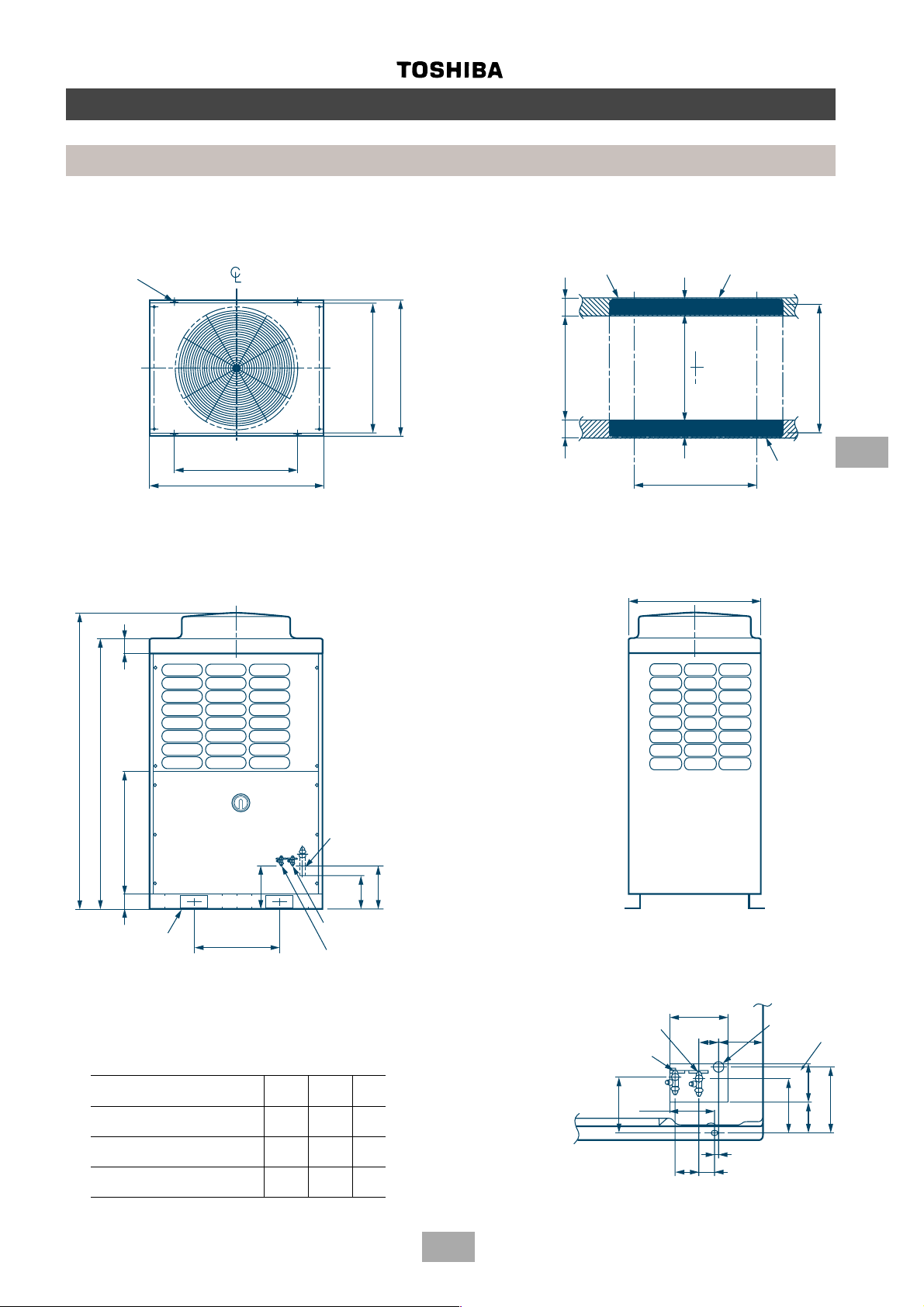
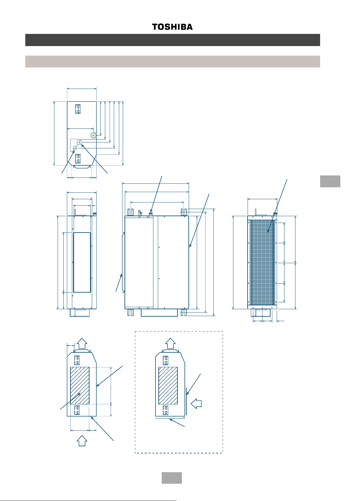
Construction views
Outdoor units
MM-A0280HT, MM-A0280HX, MM-A0224HT, MM-A0224HX, MM-A0160HX
MM-A0280CT, MM-A0280CX, MM-A0224CT, MM-A0224CX, MM-A0160CX
4 - 15 x 20 (slot)
Fixing bolt pitch
700
990
790
755
Fixing bolt pitch
(incluging fixed leg)
Grounding part of
bottom plate
610 100
100
Base
630 80
80
700
Fixing bolt pitch
Base bolt position
750
755
Fixing bolt pitch
5
Base
1700
1560
700 9088
245
2 - 60 x 150 slot
(for transport)
Note: All dimensions in mm
Model
MM-A0280HT, MM-A0280HX
MM-A0280CT, MM-A0280CX 28.6 12.7 9.52
MM-A0224HT, MM-A0224HX
MM-A0224CT, MM-A0224CX 22.2 12.7 9.52
MM-A0160HX
MM-A0160CX 22.2 9.52 9.52
500
(Slot pitch)
Balance pipe connecting
port flare connection (∅C)
∅∅
∅∅
∅A
∅B
∅∅
∅∅
mm mm mm
Refrigerant pipe connecting port
(Gas side) braze connection (∅A)
235
190
Refrigerant pipe connecting port
(Liquid side) flare connection (∅B)
∅∅
∅C
∅∅
Refrigerant pipe
connecting port
(liquid side)
Balance pipe
connecting port
145
Details of piping connections
(knock out)
130
65
173
35
60
20
115
Refrigerant pipe
connecting port
(gas side)
(knock out)
125
140
170
64
21
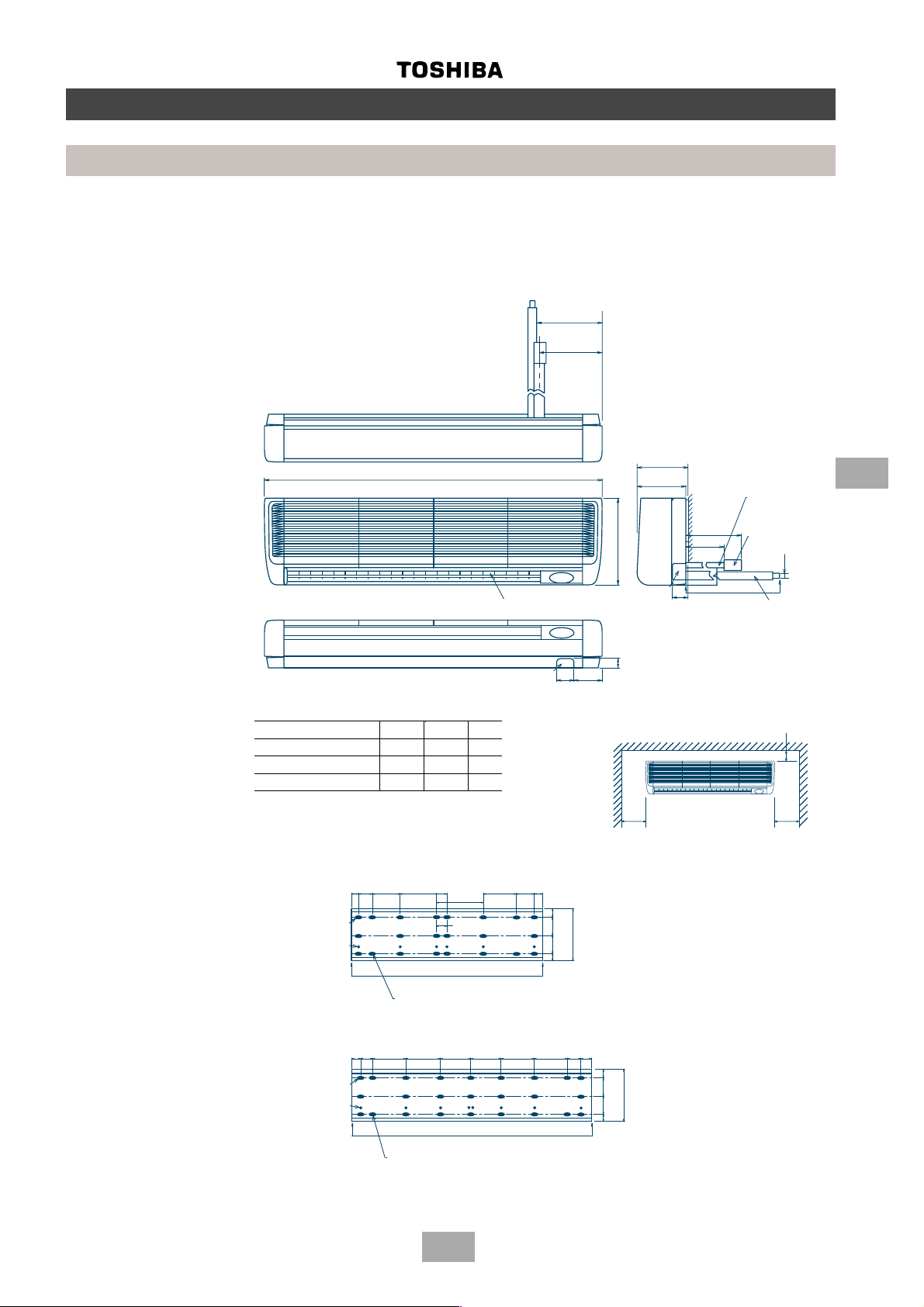
Page 22
200
450
450
300-400
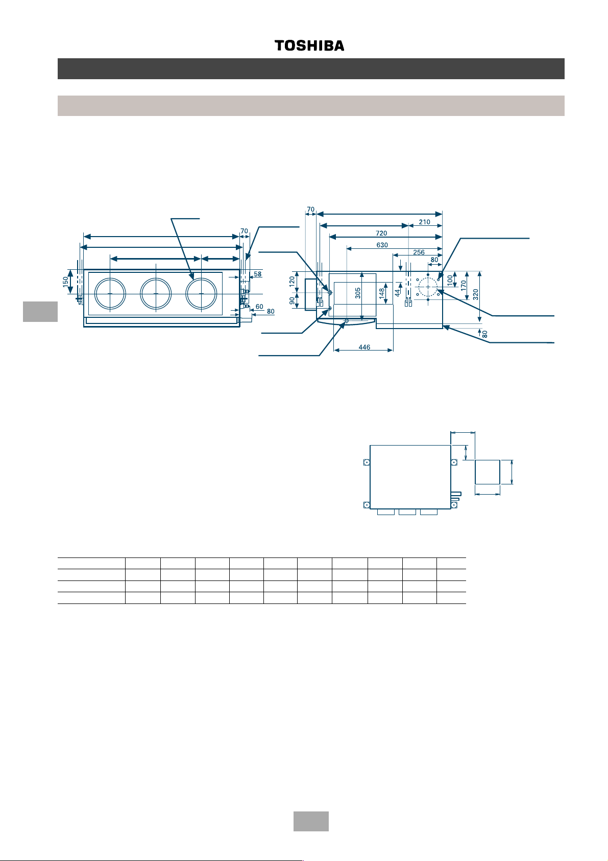
Built-In Duct
MM-B056, MM-B080, MM-B112, MM-B140
Construction views
Indoor units
6
A (Unit dimension)
B (Hanging bolt pitch)
J = M x K
N x ∅ 200
air outlet
Hanging bolt
4 - M10
provided at site
Refrigerant pipe
connection
(Gas ∅ F)
Refrigerant pipe
connection (liquid ∅ G)
Drain pipe connection
(Inner diameter: 32)
(Diameter 32 minimal for PVC pipes)
Hanging bolt pitch: 565
Unit dimension: 800
6 x ∅ 4 holes (∅160)
Fresh air inlet ∅ 125
cut-out (other side)
Filter kit
Ensure that there is sufficient space around the indoor
unit for installation and servicing
Indoor unit
Inspection hole
Model A B E
MM-B056 700 750 780 12.7 6.4 252 280 280 1 2
MM-B080 1000 1050 1080 15.9 9.5 252 580 290 2 3
MM-B112, B140 1350 1400 1430 19.0 9.5 252 930 310 3 4
(All dimensions in mm)
∅∅
∅F
∅∅
∅∅
∅GH J K M N
∅∅
Provide an inspection hole
in this position
22
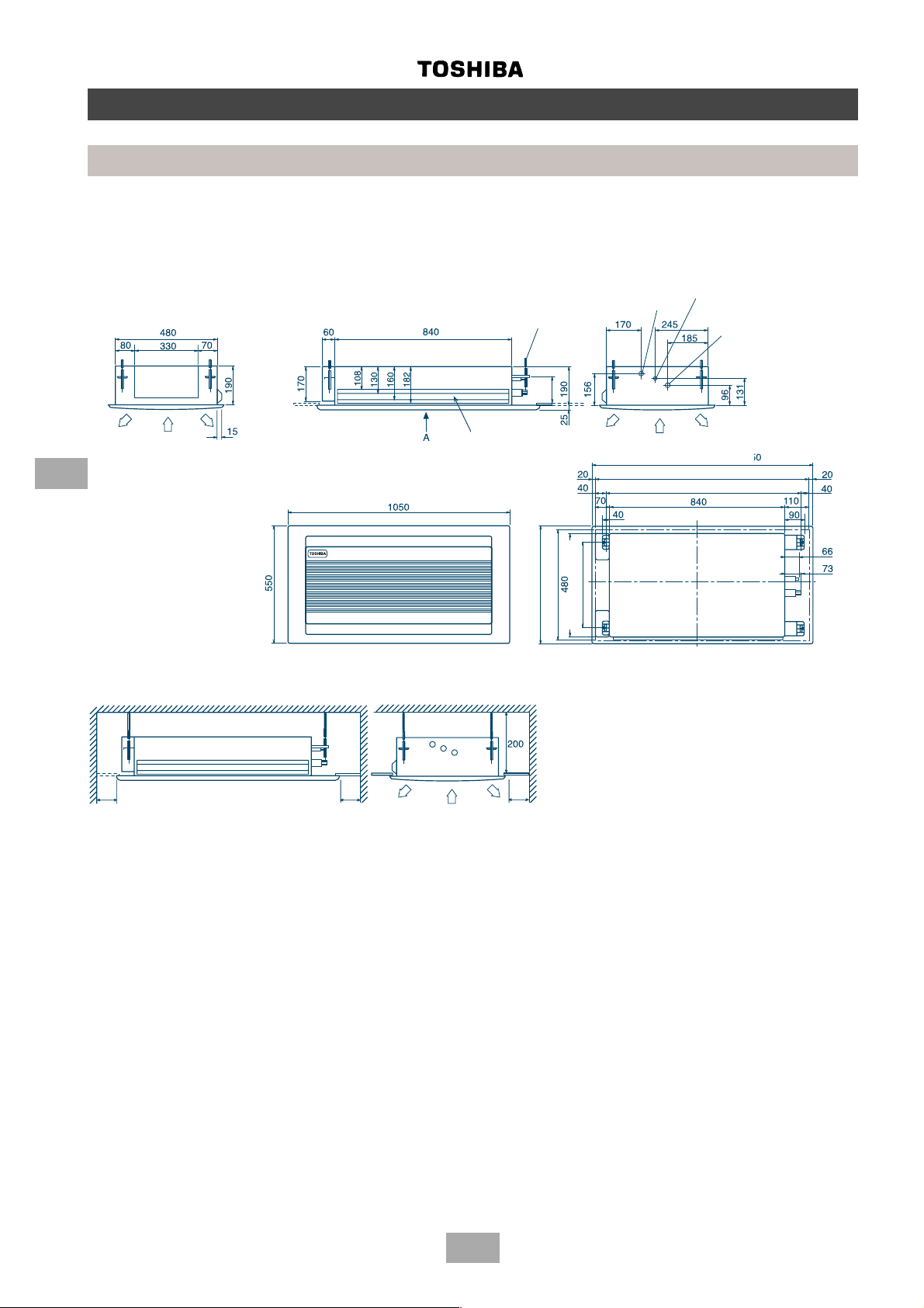
Page 23
Built-In Slim Duct
MM-SB028
480
Refrigerant pipe
connection
(Liquid ∅ 6.4)
Construction views
Indoor units
220
265
276
331
35
Refrigerant pipe
connection
12
364
(Gas ∅ 12.7)
391
480
Drain pipe connection
(1” BSP threaded connection)
500
480
397
Hanging bolt pitch
Unit dimension
Washable filter
6
Air inlet
220
200
150
35
200
150
125
700
450
125
150150
342.5
150
800
750
700
Air outlet
57
Shelter board
333
Hanging bolt pitch
Unit dimensions
Filter
700
342.5
150
75
75
37.5
158
Electrical box
(PCB, transformer and MF capacitor)
45
Air flow
81
Filter
Air flow
Shelter board
Optional air flow (lower air inlet)
23
Page 24
Construction views
Indoor units
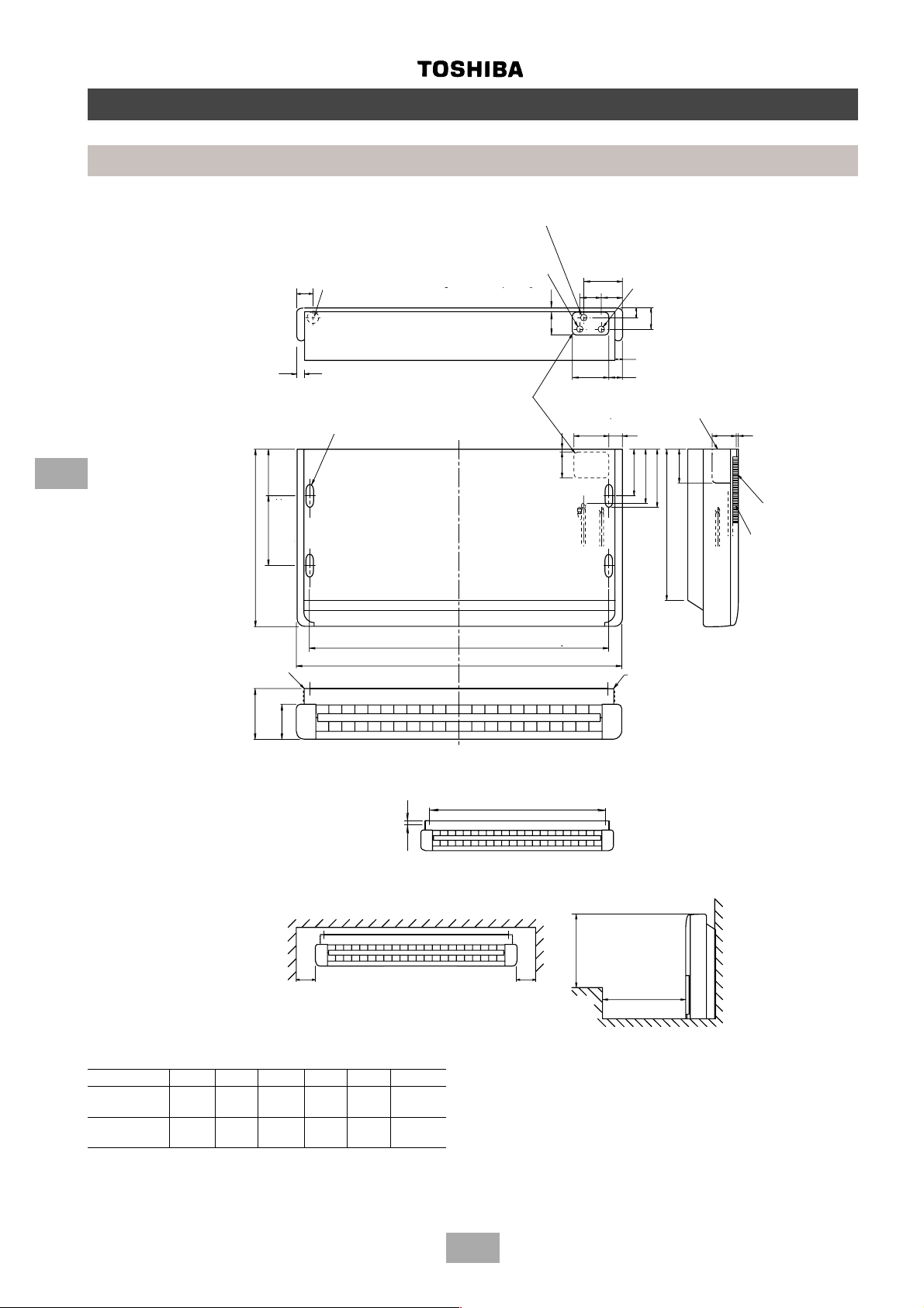
Low wall
MM-S056, MM-SR056
MM-S080, MM-SR080
6
HR-PE
640
sospensione
Hanging plate (Left)
Alternative knock-out
Foro incompleto
hole for drain piping
alternativo
62
per tubo drenaggio
30
Hanging bolt hole
4 - (12 x 25) slot
170
250
pitch
pitch
Hanging bolt
Hanging bolt
Raccordo tubo drenaggio
Tubo duro cloruro di vinile
Hard vinyl chloride pipe
diametro esterno mm. 20
outer dia. 20 mm
Collegamento tubo
Refrigerant pipe
refrigerante
connection (Liquid ∅ E)
Foro bullone di
sospensione Ð
Scanalatura 12x25 (4)
Drain piping joint
(Liquido ¿F)
Knock-out holes for
Fori incompleti
piping and wiring
per tubi e fili
Hanging bolt pitch
Passo bullone di sospensione
B
A
Collegamento tubo
Refrigerant pipe
145
refrigerante (Gas ¿G)
80
12
85
130
10
100
connection (Gas ∅ F)
80
34
78
30
50140
Right-side panel knock-
Foro incompleto pannello destro
out for piping and wiring
per tubi e fili
50
150
180
200
C
Piastra di sospensione
Hanging plate (Right)
(destra)
120
85
12
Air filter
Ingresso aria
Air inlet
Filtro aria
D
130
inferiore a 40
Hanging bolt
Less than 40
Bullone di sospensione
150
Minimum
Minimo
Space required for service and installation
Spazio necessario per installazione e manutenzione
Model A B C D ∅E ∅F
MM-S056
MM-SR056 1030 920 540 188 6.4 12.7
MM-S080
MM-SR080 580 581 582 583 584 585
All dimensions in mm
VISTA PIANO
PLAN VIEW
B
Passo bullone di sospensione interno
Hanging bolt pitch
400
150
Minimo
Minimum
Pi• di
Greater than
Pi• di
500
24
Page 25
Chassis
MM-N028, MM-N042, MM-N056, MM-N080
Space required for service and installation
20
140
160
65
150
Minimo
Foro Hx¯4.7
95
Fixing location to floor/base
10
20
Posizione di fissaggio
al pavimento/alla base
Foro ¯15 (4)
4 x ∅15 hole
Posizione di fissaggio alla parete
Fixing location to wall
Construction views
Indoor units
A
6014525
B
Uscita aria
Air outlet
C
D
t
Piastra superiore/Piastra condotto
Upper plate/duct plate
100 150
10
Minimo
Minimum
Flare joint
Raccordo a cartella
Liquid ∅ F
Liquido ¿F
Raccordo a cartella
Flare joint
Gas ¿G
Gas ∅ G
2 x ∅4.7 hole
Foro 2¯4.7
10
133
70
175
145
6
600
345
160
70
Centralina elettrica
Electrical box
Collegamento terra interno
Earth connection inside
Air filter
Filtro aria
Ingresso aria
Air intake
E
Model ABCD E∅F ∅GH
MM-N028 580 550 610 4 x 100 580 6.4 12.7 5
MM-N042
MM-N056 880 850 910 7 x 100 880 6.4 12.7 8
MM-N080 880 850 910 7 x 100 880 9.5 15.9 8
All dimensions in mm
Drain catch
315
436
397
274
224
140
65
95
104
230
155
110
Drain hose
connector
(OD ∅ 20)
Fixing location
to floor/base
25
Page 26
Construction views
Indoor units
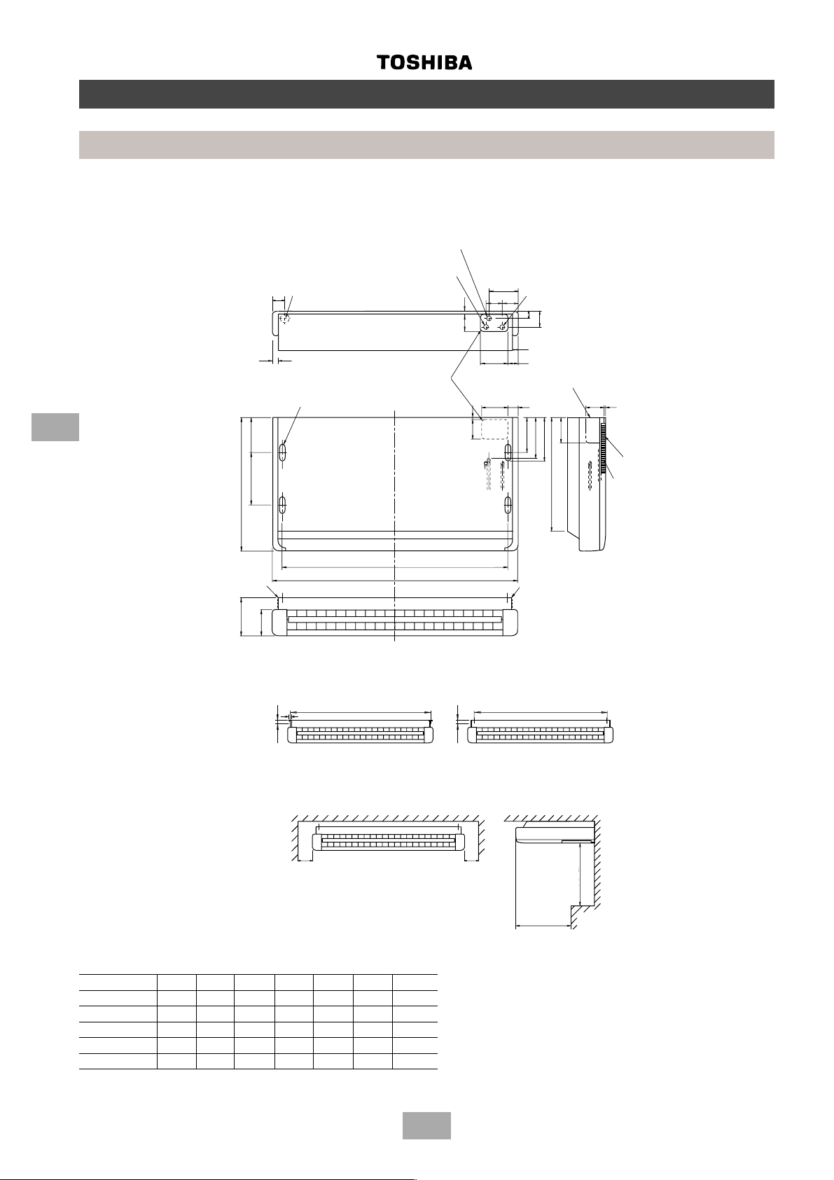
Ceiling
MM-C042, MM-CR042, MM-C056, MM-CR056
MM-C080, MM-CR080, MM-C112, MM-CR112, MM-C140, MM-CR140
6
/CHR-PE
/CHR-PE
/CHR-PE
Alternative knock-out
/CHR-PE
hole for drain piping
640
Hanging plate
Hanging plate (Left)
(Left)
D
Foro incompleto
62
alternativo
per tubo drenaggio
30
Hanging bolt hole
4 - (12 x 25) slot
170
250
Hanging bolt
130
Foro bullone di
sospensione Ð
Scanalatura 12x25 (4)
pitch
Passo bullone
di sospensione
Raccordo tubo drenaggio
Drain piping joint
Tubo duro cloruro di
vinile diametro
Hard vinyl chloride pipe
esterno mm. 20
outer dia. 20 mm
Collegamento tubo
Refrigerant pipe
refrigerante
(Liquido
connection (Liquid ∅ F)
Knock-out holes for
piping and wiring
¿F)
Fori incompleti
per tubi e fili
Hanging bolt pitch
B
(
Passo bullone di sospensione
A
Collegamento tubo
Refrigerant pipe
145
refrigerante
connection (Gas ∅ G)
80
10
100
80
34
30
50140
Foro incompleto
pannello destro
per tubi e fili
130
50
150
)
Piastra di sospensione
Hanging plate (Right)
12
85
(Gas ¿G)
78
Right-side panel knockout for piping and wiring
85
12
120
180
200
Filtro aria
C
(destra)
Air filter
Ingresso aria
Air inlet
40
Hanging bolt
inferiore a 40
Less than 40
Passo bullone di sospensione interno
Bullone di sospensione
Inner hanging bolt pitch
150
Minimo
Minimum
Spazio necessario per installazione e manutenzione
Space required for service and installation
E
Model A BCDE∅F ∅G
MM-C042/CR042 1030 920 540 188 1020 6.4 12.7
MM-C056/CR056 1030 920 540 188 1020 6.4 12.7
MM-C080/CR080 1230 1120 540 188 1220 9.5 15.9
MM-C112/CR112 1430 1320 550 240 1420 9.5 19.0
MM-C140/CR140 1630 1520 550 240 1620 9.5 19.0
All dimensions in mm
B
inferiore a 40
less than 40
Hanging bolt
Passo bullone di sospensione interno
Bullone di sospensione
Outer hanging bolt pitch
150
Minimo
Minimum
Greater than
Pi• di
400
500
Pi• di
Greater than
26
Page 27
p
Construction views
Indoor units
High wall
MM-K042, MM-K056, MM-K080, MM-KR042, MM-KR056, MM-KR080
158
143
MM-K042, MM-KR042
MM-K056, MM-KR056
MM-K080, MM-KR080
A
Piping hole
Piping hole
(Knockout hole)
(Knock-out hole)
Model A B C
MM-K042, MM-KR-042 1149 12.6 6.4
MM-K056, MM-KR056 1149 12.7 6.4
MM-K080, MM-KR080 1478 15.9 9.5
Slots
18-6x30
Slots
6-ø6 Holes
18 - 6 x 30
20 40 110 150
150
40
6 - ∅ 6 holes
600
Anchor bolt holes
Anchor bolt holes
4 - 10x20 slots
4 - 10 x 20 slots
Air outlet
Air outlet
4-way adjustable
4-way adjustable
40 20
110
43
50
26 50
226
216
595
372
(Both sides)
(Both sides)
Piping hole
Piping hole
(Knockout hole)
(Knock-out hole)
40
70 118
More than 300 More than 300
300 min.
Space required for service
169
(All dimensions in mm)
(unit : mm)
495
40
Space required for service
900
Refrigerant pipe
Refrigerant pip
connection
connection
(Liquid ∅ C)
(Liquid øC)
Refrigerant pipe
Refrigerant pi
connection
connection
(Gas øB)
(Gas ∅ B)
ø20
(OD.)
Drain pipe
Drain pipe
30 min.
More than 30
300 min.
6
Slots
Slots
21-6x30
8-ø6 Holes
21 - 6 x 30
8 - ∅ 6 holes
2040 110 150 150 150 150 110 2040
Anchor bolt holes
Anchor bolt holes
4 - 10x20 slots
4 - 10 x 20 slots
Installation board mounting bolt hole location
940
Installation board mounting bolt hole location
27
43
169
50
26 50
Page 28
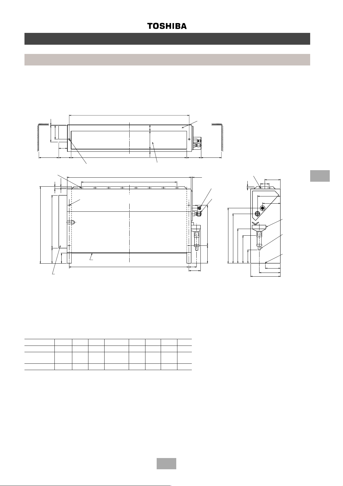
2-way cassette
MM-TU028, MM-TU042, MM-TU056
6
Construction views
Indoor units
Hanger bolt
(4 x M10)
Channel for routing TC sensors and
pressure sensor leads
Drain pipe joint
(outer ∅ 25.5)
Panel outer dimension 1050
Ceiling opening 1010
Hanging bolt pitch 930
Refrigerant piping joint
(Liquid ∅ 6.4)
Refrigerant piping joint
(Gas ∅ 12.7)
Minimum
600
View A
Minimum
600
Space required for service and installation
Ceiling opening 510
Panel outer dimension 550
Minimum
600
410
Hanging bolt pitch
(All dimensions in mm)
28
Page 29
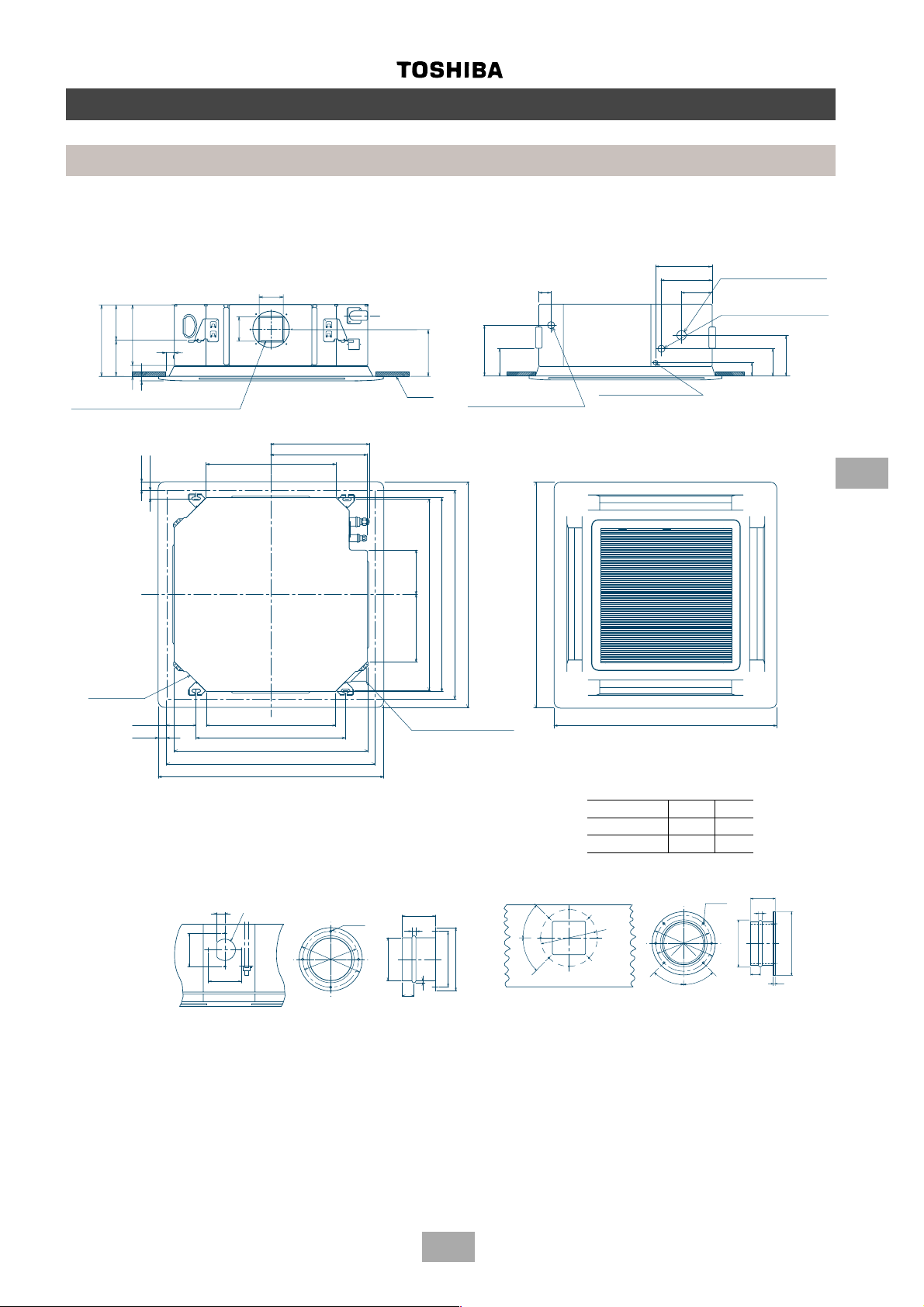
4-way cassette
MM-U056, MM-U080
Construction views
Indoor units
259
160
298
138
30
39
20
Knock-out for side ducts ∅ 150
(both sides)
40
30
Fresh air inlet
106
536
106
405
400
195
Ceiling
240
138
Drain pipe connection
(1” BSP threaded connection)
268 195
Ceiling opening 880
Hanging bolt pitch 800
Panel dimension 940
External cassette dimension 820
940
185
80
Refrigerant pipe
170
connection (Gas ∅ A)
100
Refrigerant pipe
connection (Liquid ∅ B)
200
140
73
Wiring connection
(Gland plate 3 x ∅ 20 holes)
6
130
30
Hanging bolt pitch 620
External cassette dimension 820
Ceiling opening 880
Panel dimension 940
Fresh air inlet duct size
32
130
130
∅100
536
∅144
∅130
4-∅6
Condensate pipe
(1” BSP threaded connection)
80
10
∅97
∅30
2
30
∅144
Side outlet duct size
45°
45°
940
Model (MM-) U056 U080
∅A 12.7 15.9
∅B 6.4 9.5
6-∅6
∅180
∅180
45°
45°
∅150
80
10
∅200
30
6
29
Page 30
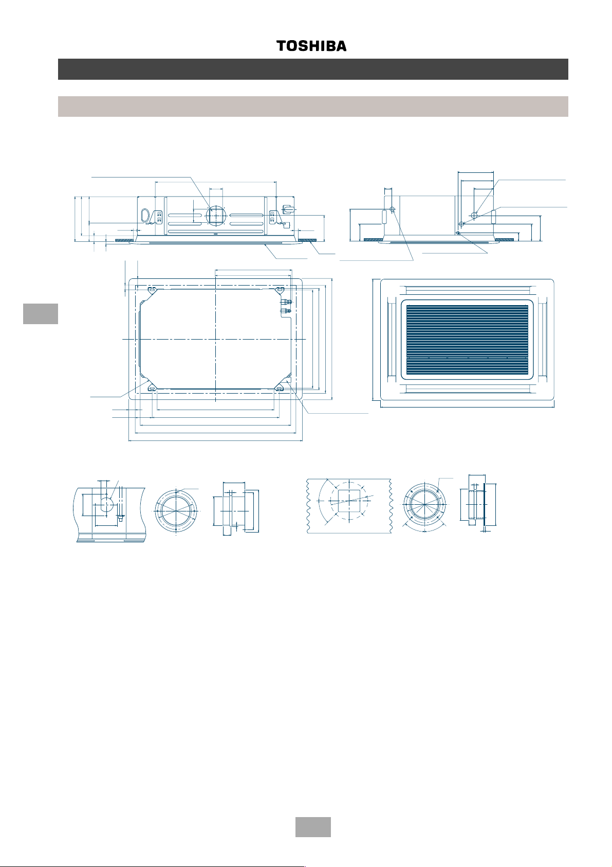
30
202
941
106
210
348
309
138
30
39
20
106
40
30
610
605
940
30
130
940
1350
80
240
138
185
170
100
73
140
200
80
10
30
6
32
130
130
80
10
30
2
4-way cassette
MM-U112, MM-U140
Construction views
Indoor units
6
Knock-out for side ducts ∅ 150
(both sides)
Fresh air
inlet
Hanging bolt pitch 1030
External cassette dimension 1230
Ceiling opening 1290
Panel dimension 1350
Ceiling
Ceiling panel
Drain pipe connection
(1” BSP threaded connection)
Hanging bolt pitch 800
External cassette dimension 820
Condensate pipe
(1” BSP threaded connection)
Ceiling opening 880
Panel dimension 940
Refrigerant pipe
connection
(Gas side ∅19.0)
Refrigerant pipe
connection
(Liquid side ∅9.5)
Wiring connection
(Gland plate 3 x ∅ 20 holes)
Fresh air inlet duct size
Side outlet duct size
6-∅6
45°
∅150
∅200
∅100
45°
45°
∅180
45°
4-∅6
∅144
∅130
∅97
∅30
∅144
30
Page 31

Inverter unit (10 HP, 8 HP)
1212121212
12
MM-A0280HT, MM-A0224HT
Symbol Part name
CM 1, 2 Compressor
FM Fan motor
52C 1, 2 Electromagnetic contactor for
compressor
49C 1, 2 Inner overload relay
51C Overload relay
PMV 1, 2, 3 Electronic flow control valve
63H 1, 2 High pressure switch
RC Running capacitor
SV 42, 2 2-way valve
3A, 3B, 3C
20SF 4-way valve
Tr Transformer
AH Accumulator heater
TD 1, 2 TE Temperature sensor
TK 1, 2, 3 TS
Ferrite core
FL 1, 2, 3 Fuse 20 A
31
Posistor
Filter board
MCC - 1366 - 01
REDREDRED
CN01
CN17
WHI
CN18
CN02
BLK
CN19
CN03
GRY
CN04
CN20
CN22
CN23
3 1
3 1
(WHI) (BLU)
3 1
3 1
WHI
RED
GRY
GRY
GRY
GRY
GRY
Q
Y
P
X
GRY
Q
P
Q
P
Y
X
Isolator
BLK
WHI
RED
L1 L2 L3
N
N T1 T2 T3 E
N L1 L2 L3 E
Power supply
3N, 380/415 V, 50 Hz
BLK
SV42
SV2
SV3A
SV3B
SV3C
AH
20SF
BLK
4 2 1
4 2 1
GRY
FL1
RED
FL2
WHI
BLK
GRY
GRY
PMV
1
RED
BLU
ORG
YEL
WHI
6 4 3 2 1
6 4 3 2 1
(WHI)
CN300
(BLU)
BLU
5 5
BLU
7 7
CN311
BLU
1 1
BLU
3 3
(BLK)
BLU
5 5
BLU
7 7
CN312
BLU
1 1
(BLU)
BLU
3 3
CN313
BLU
1 1
(BLK)
BLU
3 3
CN314
ORG
1 1
(RED)
ORG
3 3
CN316
BLU
3 3
(BLU)
BLU
1 1
CN317
BLK
3 3
3 3
(WHI)
RED
1 1
1 1
CN304
GRY
RC
WHI
RED
(WHI)
51C 52C1
PNK
WHI
U V W
FM
WHI
RED
BLK
CM2
(D.O.L.)
RED
RED
6 4 3 2 1
6 4 3 2 1
GRY
YEL
ORG
12
12
49C2
RED
R
S
52C2
RED
PMV
PMV
3
2
BLU
ORG
YEL
WHI
GRY
RED
BLU
ORG
YEL
WHI
6 5 4 3 2 1
21
6 5 4 3 2 1
21
(RED)
(WHI)
CN301
(RED)
ORG
(WHI)
CN302
CN602
D801
D802
Interface control PC board
Interface Control PC Board
(WHI)
CN308
5 3 1
5 3 1
5 3 1
5 3 1
BLK
PUR
BRN
1 2 3 4
(RED)
BLK
RED
BLK
63H2
RED
U
V
BLU
TK3
TD1
TS1TETD2
BLK
BLK
BLK
21
21
(BLU)
CN601
12
12
(WHI)
CN604
(BLK)
CN307
5 3 1
5 3 1
5 3 1
5 3 1
BRN
ORG
6 5 4 3 2 1
6 5 4 3 2 1
MCC
GRY
(WHI)
CN600
-
1343 - 03
5 3 1
5 3 1
5 3 1
5 3 1
BLK
21
(WHI)
(BLU)
CN505
CN504
1 2 3 4
ON
SW04
SW05
SW03 SW02 SW01
D716 D717 D715D714
5 3 1
5 3 1
5 3 1
5 3 1
BLK
BLK
BLK
3 1
212121
3 1
(RED)
CN503
1 2 3 4
ON
SW06
SW07
(BLU)
CN401
1 3
1 3
BLK
3 1
3 1
(WHI)
CN502
GRY
(WHI)
CN400
1 3
1 3
RED
BLK
BLK
BLK
3 1
3 1
(GRN)
CN507
1 2
ON
SW08
1 2
ON
SW09
CN402
WHI
CN403
(RED)
CN501
(BLU)
CN500
(WHI)
CN100
(BLK)
CN516
4
3
1
4
3
2
3
1
3
1
CN515
3
1
RED
WHI
RED
4
Pressure
3
BLK
sensor
1
WHI
PD
RED
Pressure
4
BLK
3
sensor
2
WHI
PS
BLU
3
BLU
1
BLK
3
TK1
BLK
1
(BLU)
BLK
3
TK2
BLK
1
BLU
BLU
1. The dashed line indicates wiring on the site.
2. and indicates terminal blocks and the numbers
within them are terminal numbers.
3. indicates a printed circuit board.
FL3
RED
11
GRY
33
BLK
33
ORG
11
RED
11
BLU
33
BLK
BLK
YEL
BLU
Parts layout
RC
MCC-1366-01
MCC-1343-03
RED
CN01
WHI
CN02
BLK
CN03
T02
(BLK)
CN04
(BLK)
CN501
(BLU)
CN06
CN10
T03
CN11
CN08
CN09
WHI
WHI
(WHI)
WHI
WHI
Reactor
MCC-1342-01
IPDU board
MCC - 1342 - 01
CN14
CN15
CN16
D406
PO4
PO5
BLU
BLU
(WHI)
WHI
WHI
Reactor
Electrolytic
Electolytic
Capacitor
capacitor
(WHI)
CN07
12345
12345
RED
PINK
BLU
WHI
BLK
FL1
FL2
FL3
52C2
L1 L2 L3
Power supply
Power Supply
WHI
RED
CM1
Posistor
Posistor
N
BLK
52C1
51C2
BLK
ORG
12
(BLK)
12
BLK
63H1
BLK
ORG
ORG
Outdoor units
Wiring diagrams
49C1
X YP Q
7
Page 32

Fixed-speed unit (10 HP, 8 HP)
3
3
3
3
MM-A0280HX, MM-A0224HX
Wiring diagrams
Outdoor units
7
TK3
TD1
TD2
TS
TE
PMV
PMV
PMV
(BLU)
5
5
BLU
BLU
3
3
(WHI)
D802
7
7
BLU
SV42
BLU
1
1
CN100
CN311
TK1
BLK
BLK
3
1
3
1
(BLK)
CN516
1 2
SW09
SW03 SW02 SW01
03
1343
-
ON
D716 D717 D715D714
1 2
ON
1 2 3 4
ON
1 2 3 4
ON
SW04
SW08
SW07
SW06
SW05
MCC
Interface Control PC Board
Interface control PC board
BLU
(BLK)
3 3
1 1
BLU
SV2
BLU
5 5
7 7
CN312
BLU
SV3A
1 1
BLU
(BLU)
3 3
BLU
SV3B
CN313
1 1
BLU
(BLK)
3 3
CN314
BLU
SV3C
ORG
(WHI)
(RED)
3 3
3 3
1 1
1 1
ORG
ORG
CN316
3 3
BLU
ORG
CN315
AH
PD
sensor
Pressure
BLK
RED
431
431
(RED)
CN501
BLK
3 1
3 1
BLK
(GRN)
CN507
321
BLK
3 1
3 1
BLK
CN502
BLK
3 1
BLK
(RED) (WHI)
CN503
BLK
21
21
BLK
(WHI)
CN504
BLK
21
21
BLK
(BLU)
CN505
21
21
(BLU)
CN601
21
WHI
YEL
ORG
3
BLU
RED
(RED)
CN302
GRY
6 5 4 3 2 1
6 5 4 3 2 1
WHI
YEL
ORG
2
BLU
(WHI)
CN301
RED
6 4 3 2 1
6 4 3 2 1
WHI
YEL
ORG
1
BLU
(WHI)
CN300
RED
6 4 3 2 1
6 4 3 2 1
PS
sensor
Pressure
BLK
RED
WHI
WHI
432
432
(BLU)
CN500
12
(WHI)
CN604
D801
3 3
1 1
BLU
BLU
SV41
CH
GRY
GRY
P Q
P QP Q
Surge absorber
(BLU)
BLU
20SF
1 1
01
-
1357
-
MCC
CN317
(BLU)
3 3
3 3
CN02
CN01
BLK
CN515
(WHI)
1 1
1 1
3
3
(WHI)
(BLU)
(RED)
(BLU)
(BLK)
(WHI)
BLK
(BLU)
3 1
3 1
(WHI)
TK2
BLK
1
1
CN403
CN402
CN400
CN401
CN305
CN306
CN307
CN308
CN304
CN03
3 1
3 1
1 3
1 3
5 3 1
5 3 1
5 3 1
5 3 1
5 3 1
5 3 1
5 3 1
RED
BLU
RED
WHI
RED
1 3
1 3
BLK
5 3 1
5 3 1
5 3 1
5 3 1
5 3 1
5 3 1
5 3 1
GRY
BLK
BLU
GRY
PUR
BLK
BRN
1 2 3 4
1 2 3 4
1234
1234
(RED)
YEL
ORG
BRN
RED
BLK
51C1 52C1
GRY
BLK
WHI
CM1
RED
(D.O.L.)
12
12
(RED)
49C1
WHI
GRY
GRY
63H1
GRY
ORG
BRN
12
12
BLK
W
V
U
51C2 52C2
L3
L2
L1
ORG
(BLK)
49C2
BLK
WHI
CM2
RED
N
(D.O.L.)
N T1 T2 T3 E
N L1 L2 L3 E
Power supply
3N, 380/415 V, 50 Hz
PUR
BLK
BRN
GRY
RC
GRY
WHI
RED
RED
1 2 3 4
1 2 3 4
(BLK)
YEL
RED
63H2
(WHI)
RED
FM
4 2 1
4 2 1
BLK
WHI
ORG
GRY
WHI
GRY
BLK
WHI
RED
Isolator
P Q
N
Symbol Part name
CM 1, 2 Compressor
FM Fan motor
52C 1, 2 Electromagnetic contactor for compressor
49C 1, 2 Inner overload relay
51C 1, 2 Overload relay
PMV 1, 2, 3 Electronic flow control valve
63H 1, 2 High pressure switch
RC Running capacitor
SV 41, 42, 2 2-way valve
3A, 3B, 3C
20SF 4-way valve
CH Crankcase heater
Tr Transformer
AH Accumulator heater
TD1, 2 TE Temperature sensor
Ferrite core
TK1, 2, 3 TS
MCC-1357-01
RC
MCC-1343-03
Parts layout 10, 8 HP (Fixed)
L1 L2 L3
52C1
51C1
U V W
R S T
Tr
2
52C
U V W
R S T
51C2
2
2
2
2
within them are terminal numbers.
1. The dashed line indicates wiring on the site.
2. and indicates terminal blocks and the numbers
3. indicates a printed circuit board.
32
Page 33

3
3
3
3
3
Fixed-speed unit (6 HP)
MM-A0160HX
MM-A0160CX
PD
sensor
Pressure
BLK
RED
WHI
431
431
(RED)
CN501
BLK
3 1
TK3
TD1
TS
TE
3 1
BLK
(GRN)
CN507
321
BLK
3 1
3 1
BLK
(WHI)
CN502
3 1
BLK
21
21
BLK
(WHI)
CN504
BLK
21
21
BLK
(BLU)
CN505
Pressure
RED
432
432
(BLU)
sensor
BLK
PS
WHI
CN500
Wiring diagrams
Outdoor units
(BLU)
BLK
3
CN515
3
(WHI)
(BLU)
(RED)
(BLU)
TK2
BLK
1
1
CN403
CN402
CN400
CN401
CN305
CN306
BLU
RED
1 3
1 3
1 3
1 3
BLK
5 3 1
5 3 1
5 3 1
5 3 1
5 3 1
5 3 1
BLU
GRY
PUR
BLK
BRN
1 2 3 4
1 2 3 4
1234
1234
(RED)
YEL
ORG
BRN
RED
BLK
51C1 52C1
GRY
BLK
63H1
)
BLK
WHI
CM1
D.O.L.
RED
(
12
12
(RED)
49C1
7
WHI
GRY
GRY
WHI
RED
TK1
BLK
BLK
BLU
BLU
3
1
3
1
3
1
3
1
(BLK)
(WHI)
CN516
CN100
1 2
SW09
SW03 SW02 SW01
ON
D716 D717 D715D714
1 2
ON
1 2 3 4
ON
1 2 3 4
ON
SW04
SW08
SW07
SW06
SW05
PMV
PMV
(BLU)
(RED)
(WHI)
CN601
CN302
CN300
12
(WHI)
CN604
D801
D802
03
1343
-
5 3 1
5 3 1
MCC
Interface control PC board
Interface Control PC Board
(BLU)
5
5
3 3
1 1
BLU
BLU
SV41
GRY
GRY
P Q
(BLK)
7
7
3 3
1 1
CN311
BLU
BLU
BLU
SV2
P QP Q
5 5
7 7
CN312
BLU
SV3A
1 1
BLU
(BLU)
3 3
BLU
SV3B
CN313
1 1
BLU
(BLK)
3 3
CN314
BLU
SV3C
ORG
(WHI)
(RED)
(BLU)
(WHI)
1 1
CN316
BLU
3 3
3 3
3 3
1 1
1 1
CN317
CN304
BLU
GRY
20SF
BLK
RED
GRY
BLK
WHI
RED
RC
(WHI)
WHI
RED
FM
4 2 1
4 2 1
3 3
3 3
1 1
1 1
CN315
ORG
ORG
ORG
AH
CH
CN03
01
CN02
1357
CN01
MCC
Surge absorber
3 1
3 1
(BLU)
(WHI)
GRY
3 1
3 1
BLK
WHI
RED
L3
L2
L1
N
Power supply
N T1 T2 T3 E
N L1 L2 L3 E
3N, 380/415 V, 50 Hz
21
21
21
WHI
YEL
ORG
3
BLU
RED
GRY
6 5 4 3 2 1
6 5 4 3 2 1
6 4 3 2 1
WHI
YEL
ORG
1
BLU
RED
6 4 3 2 1
6 4 3 2 1
Isolator
P Q
N
Symbol Part name
CM 1 Compressor
FM Fan motor
52C 1 Electromagnetic contactor for compressor
49C 1 Inner overload relay
51C 1 Overload relay
PMV 1, 3 Electronic flow control valve
63H 1 High pressure switch
RC Running capacitor
SV 41, 2 2-way valve
3A, 3B, 3C
20SF 4-way valve
CH Crankcase heater
Tr Transformer
AH Accumulator heater
TD1 TE Temperature sensor
Ferrite core
TK1, 2, 3 TS
MCC-1357-01
RC
MCC-1343-03
Parts layout 6 HP (Fixed)
L1 L2 L3
1
52C151C
U V W
R S T
Tr
2
52C
U V W
R S T
2
51C
2
2
2
2
2
within them are terminal numbers.
1. The dashed line indicates wiring on the site.
2. and indicates terminal blocks and the numbers
3. indicates a printed circuit board.
33
Page 34

Inverter unit (10 HP, 8 HP) Cooling only
3
3
3
3
MM-A0280CT, MM-A0224CT
01
1342
MCC
IPDU board
CN02
CN03
CN01
BLK
RED
WHI
CN14
CN15
CN16
T02
(BLK)
(BLK)
CN04
11
33
33
RED
GRY
BLK
FL3
CN501
11
ORG
D406
PO4
PO5
CN09
T03
CN08
CN11
CN10
(BLU)
CN06
33
11
RED
BLK
BLU
Wiring diagrams
Outdoor units
ORG
12
12
BLK
BLK
63H1
(BLK)
(WHI)
CN07
12345
12345
BLU
(WHI)
BLU
WHI
WHI
WHI
WHI
(WHI)
YEL
BLU
BLK
BLK
BLK
WHI
BLU
RED
PINK
WHI
WHI
Reactor
ORG
BLK
WHI
RED
Reactor
ORG
49C1
CM1
Posistor
Posistor
FL1
Parts layout
52C1
FL2
FL3
MCC-1342-01
RC
51C2
52C2
L1 L2 L3
N
Power Supply
Power supply
MCC-1366-01
X YP Q
Electolytic
Capacitor
Electrolytic
capacitor
MCC-1343-03
7
Posistor
V
U
RED
S
R
RED
RED
FL1
FL2
RED
WHI
01
-
CN18
CN17
1366
-
CN02
CN01
Filter board
MCC
REDREDRED
WHI
03
1343
MCC
3 3
3 3
CN317
BLK
(WHI)
TK2
BLU
BLU
BLK
BLK
3
1
(BLU)
CN515
3
1
WHI
RED
CN403
CN402
WHI
(WHI)
RED
1 3
1 3
CN400
GRY
BLK
1 3
1 3
(BLU)
CN401
5 3 1
5 3 1
5 3 1
5 3 1
2
5 3 1
5 3 1
5 3 1
5 3 1
GRY
ORG
(BLK)
CN307
5 3 1
5 3 1
BRN
5 3 1
5 3 1
PUR
RED
BLK
(WHI)
CN308
5 3 1
5 3 1
5 3 1
5 3 1
BRN
1 1
1 1
CN304
RED
BLK
1 2 3 4
BLK
63H2
(RED)
GRY
YEL
GRY
RC
GRY
Y
GRY
X
GRY
Q
GRY
P
WHI
RED
4 2 1
BLK
GRY
51C 52C1
(WHI)
WHI
PNK
GRY
4 2 1
BLK
W
V
U
FM
L3
WHI
L2
RED
L1
Y
X
Q
P
2
2
2
within them are terminal numbers.
1. The dashed line indicates wiring on the site.
2. and indicates terminal blocks and the numbers
3. indicates a printed circuit board.
ORG
(RED)
12
12
ORG
CM2
N T1 T2 T3 E
N L1 L2 L3 E
49C2
(D.O.L.)
Power supply
BLK
WHI
RED
N
3N, 380/415 V, 50 Hz
Isolator
TK1
Pressure
Pressure
sensor PS
sensor PD
BLK
RED
431
431
(RED)
CN501
BLK
(GRN)
BLK
3 1
3 1
TK3
TD1
TD2
TS1
TE
BLU
3
PMV
RED
52C2
2
PMV
1
PMV
GRY
BLK
GRY
BLK
3 1
3 1
GRY
CN23
CN19
CN20
RED
3 1
3 1
WHI
CN22
CN04
CN03
(WHI) (BLU)
BLK
GRY
CN507
BLK
3 1
BLK
3 1
(WHI)
CN502
BLK
BLK
3 1
3 1
(RED)
CN503
BLK
BLK
21
21
(WHI)
CN504
BLK
21
BLK
21
(BLU)
CN505
(WHI)
CN600
6 5 4 3 2 1
6 5 4 3 2 1
21
21
(BLU)
CN601
21
21
(WHI)
CN602
WHI
YEL
ORG
BLU
(RED)
RED
CN302
6 5 4 3 2 1
6 5 4 3 2 1
GRY
WHI
YEL
ORG
BLU
(WHI)
CN301
6 4 3 2 1
6 4 3 2 1
RED
WHI
YEL
ORG
BLU
(WHI)
CN300
6 4 3 2 1
6 4 3 2 1
RED
BLU
BLU
BLK
BLK
RED
WHI
432
432
(BLU)
CN500
12
12
BLK
WHI
3
1
3
1
3
1
3
1
(WHI)
(BLK)
CN100
CN516
1 2
1 2
SW08
ON
SW07
1 2 3 4
ON
SW06
1 2 3 4
ON
SW04
SW05
(WHI)
CN604
D801
D802
(BLU)
(BLK)
(BLU)
3 3
7 7
1 1
7 7
5 5
5 5
CN311
BLU
BLU
BLU
SV42
BLU
SV2
1 1
CN312
BLU
BLU
BLU
SV3B
SV3A
SW09
ON
SW03 SW02 SW01
D716 D717 D715D714
Interface Control PC Board
Interface control PC board
(BLK)
3 3
3 3
1 1
CN314
CN313
BLU
BLU
BLU
SV3C
(BLU)
(RED)
3 3
3 3
1 1
1 1
CN316
ORG
BLU
BLU
ORG
20SF
AH
Q
P
Symbol Part name
CM 1, 2 Compressor
FM Fan motor
52C 1, 2 Electromagnetic contactor for
compressor
49C 1, 2 Inner overload relay
51C Overload relay
PMV 3 Electronic flow control valve
63H 1, 2 High pressure switch
RC Running capacitor
SV 42, 2 2-way valve
3A, 3B, 3C
Tr Transformer
Ferrite core
AH Accumulator heater
TD 1, 2 TE Temperature sensor
TK 1, 2, 3 TS
FL 1, 2, 3 Fuse 20 A
34
Page 35

Fixed-speed unit (10 HP, 8 HP) Cooling only
12
12
12
12
12
12
12
MM-A0280CX, MM-A0224CX
Wiring diagrams
Outdoor units
TK3
TD1
TD2
TS
TE
PMV
PMV
PMV
(BLU)
5
5
BLU
BLU
3
3
(WHI)
D802
BLU
SV42
7
7
BLU
1
1
CN100
CN311
TK1
BLK
BLK
3
1
3
1
(BLK)
CN516
1 2
SW09
SW03 SW02 SW01
03
1343
-
ON
D716 D717 D715D714
1 2
ON
1 2 3 4
ON
1 2 3 4
ON
SW04
SW08
SW07
SW06
SW05
MCC
Interface Control PC Board
Interface control PC board
BLU
(BLK)
3 3
1 1
BLU
SV2
BLU
5 5
7 7
BLU
SV3A
CN312
BLU
(BLU)
1 1
3 3
BLU
SV3B
CN313
1 1
BLU
(BLK)
3 3
CN314
BLU
SV3C
ORG
(WHI)
(RED)
3 3
3 3
1 1
1 1
ORG
ORG
CN316
3 3
BLU
ORG
CN315
AH
PS
PD
sensor
sensor
Pressure
Pressure
BLK
BLK
RED
RED
WHI
432
432
(BLU)
12
BLU
CN500
(WHI)
1 1
WHI
CN604
D801
3 3
BLU
431
431
(RED)
CN501
BLK
3 1
3 1
BLK
(GRN)
CN507
321
BLK
3 1
3 1
BLK
CN502
BLK
3 1
BLK
(RED) (WHI)
CN503
BLK
21
21
BLK
(WHI)
CN504
BLK
21
21
BLK
(BLU)
CN505
21
21
(BLU)
CN601
21
WHI
YEL
ORG
3
BLU
RED
(RED)
CN302
GRY
6 5 4 3 2 1
6 5 4 3 2 1
WHI
YEL
ORG
2
BLU
(WHI)
CN301
RED
6 4 3 2 1
6 4 3 2 1
WHI
YEL
ORG
1
BLU
(WHI)
CN300
RED
6 4 3 2 1
6 4 3 2 1
SV41
CH
GRY
GRY
P Q
P QP Q
Surge absorber
(BLU)
BLU
20SF
1 1
01
-
1357
-
MCC
(BLU)
CN317
3 3
3 3
CN02
CN01
BLK
3
CN515
3
(WHI)
1 1
1 1
(WHI)
(BLU)
(RED)
(BLU)
(BLK)
(WHI)
BLK
(BLU)
3 1
3 1
(WHI)
TK2
BLK
1
1
CN403
CN402
CN400
CN401
CN305
CN306
CN307
CN308
CN304
CN03
3 1
3 1
BLU
RED
1 3
1 3
1 3
1 3
5 3 1
5 3 1
5 3 1
5 3 1
5 3 1
5 3 1
5 3 1
5 3 1
5 3 1
5 3 1
5 3 1
5 3 1
5 3 1
5 3 1
RED
BLU
GRY
PUR
BLK
BRN
1 2 3 4
1 2 3 4
1234
1234
(RED)
YEL
ORG
BRN
RED
BLK
51C1 52C1
GRY
BLK
WHI
CM1
RED
(D.O.L.)
12
12
(RED)
49C1
7
WHI
GRY
GRY
WHI
RED
BLK
63H1
GRY
ORG
BRN
12
12
BLK
W
V
U
51C2 52C2
L3
L2
L1
ORG
(BLK)
49C2
BLK
WHI
CM2
RED
N
(D.O.L.)
N T1 T2 T3 E
N L1 L2 L3 E
Power supply
30N, 380/415 V, 50 Hz
PUR
BLK
BRN
GRY
GRY
BLK
WHI
RED
RC
GRY
RED
1 2 3 4
1 2 3 4
(BLK)
YEL
WHI
RED
63H2
(WHI)
RED
FM
4 2 1
4 2 1
BLK
ORG
GRY
WHI
GRY
BLK
WHI
RED
Isolator
P Q
N
Symbol Part name
CM 1, 2 Compressor
FM Fan motor
52C 1, 2 Electromagnetic contactor for compressor
49C 1, 2 Inner overload relay
51C 1, 2 Overload relay
PMV 3 Electronic flow control valve
63H 1, 2 High pressure switch
RC Running capacitor
SV 41, 42, 2 2-way valve
3A, 3B, 3C
CH Crankcase heater
Tr Transformer
AH Accumulator heater
TD1, 2 TE Temperature sensor
TK1, 2, 3 TS
Ferrite core
MCC-1357-01
RC
MCC-1343-03
Parts layout 10, 8 HP (Fixed)
L1 L2 L3
52C1
51C1
U V W
R S T
Tr
2
52C
51C2
U V W
R S T
within them are terminal numbers.
1. The dashed line indicates wiring on the site.
2. and indicates terminal blocks and the numbers
3. indicates a printed circuit board.
35
Page 36

Built-In Duct
MM-B140, MM-B112, MM-B080, M-B056
Wiring diagrams
Indoor units
TA
TC2
TC1
RED
CN04
22
11
WHI
CN05
22
11
BLU
CN20
22
11
YEL
CN23
66
GRN
44
PS
WHI
BLK
22
11
7
WHI
RC
GRN/YEL
FM
GRY
RED
YEL
BLU
ORN
BLK
BRN
WHI
2
2
1
1
CN01 CN12
BLK
2
2
YEL
1
1
FC
1
1
2
2
3
3
4
4
5
5
6
6
7
7
8
8
9
9
RED
WHI
BLK
BLK
ORN
BLU
YEL
RED
CN26
5
3
1
5
3
1
CN07 CN25
1
3
5
7
9
5
3
1
22
BLU
22
33
33
BLU
44
55
RY02 RY03 RY04
CN28
CN27
WHI
11
BLU
11
22
BLU
22
RY01
33
BLU
33
44
BLU
44
55
BLU
55
66
66
BLK
MCC-1355-01
3
3
2
2
1
1
RED WHI
CN50 CN16
2
2
1
1
ORN
BLU
TR
A
ORN
11
YEL
22
BLU
B
33
11
CN10
WHI
BLU
114422
CN51
5
3
1
HMLUL
1
3
5
7
9
BLK
2
2
1
1
MCC-1361-01
31 31
6
6
5
5
4
4
3
3
2
2
1
1
CN101 CN25 CN08 CN09 CN11
2
2
1
1
CN02
C
RED
BRN
BLU
ORN
YEL
WHI
RED
5
5
BRN
2
2
BLU
1
1
ORN
3
3
PMV
YEL
4
4
WHI
6
6
GRY
GRY
Q
P
F
1
1
2
2
GRN/YEL
RED
3
3
YEL
4
4
FM
BLU
5
5
ORN
6
6
BLK
7
BRN
7
8
8
9
9
WHI
GRY
Increase fan speed option
RC
RED
YEL
ORN
BLK
BRN
1
2
3
3
4
4
5
5
6
6
7
7
8
8
9
9
CN03
RED
L
Power supply
1
2
11
RED
220/240 V –
RED
YEL
BLU
ORN
BLK
33
WHI
N
50 Hz
(accessory)
Connector assembly
Symbol Part name
36
F Fuse (PCB)
FM Fan motor
PMV Pulse modulating valve
A
PS Pressure sensor
RC Running capacitor
RY01-RY04 Relay
TA Temperature sensor
B
C
Remote
controller
(Optional)
TC1 Temperature sensor
TC2 Temperature sensor
TR Transformer
Q
P
Communication
numbers within them are terminal numbers.
1. The dashed line indicates wiring on the site.
2. and indicates terminal blocks and the
Page 37

Ceiling
MM-C042, MM-CR042, MM-C056, MM-CR056
MM-C080, MM-CR080, MM-C112, MM-CR112
MM-C140, MM-CR140
Wiring diagrams
Indoor units
7
50 Hz
220/240 V –
Power supply
Remote
controller
(Optional)
Infrared
receiver
(IR model)
Communication
Symbol Part name
F Fuse (PCB)
37
FM Fan motor
PMV Pulse modulating valve
PS Pressure sensor
RC Running capacitor
RY01-RY04 Relay
TA Temperature sensor
TC1 Temperature sensor
TC2 Temperature sensor
TR Transformer
within them are terminal numbers.
1. The dashed line indicates wiring on the site.
2. indicates terminal blocks and the numbers
Page 38

Wall unit
MM-K042, MM-K056, MM-K080,
MM-KR042, MM-KR056, MM-KR080
Wiring diagrams
Indoor units
TA
TC2
TC1
RED
CN04
22
11
WHI
CN05
22
11
BLU
CN20
22
11
YEL
CN23
66
GRN
44
WHI
22
BLK
11
7
GRN/YEL
FM
WHI
RED
YEL
BLU
ORN
BLK
WHI
2
2
1
1
CN01 CN12
BLK
2
2
YEL
1
1
BLK
MCC-1355-
3
3
1
1
CN50 CN16
2
2
1
1
RED WHI
RY07
ORN
BLU
TR
A
CN26
5
5
3
3
1
1
11
22
11
22
CN10
WHI
CN51
CN51
RED
WHI
BLK
5
5
3
3
1
1
CN07 CN25
HMLUL
BLK
1
ORN
BLU
YEL
RED
1
3
3
5
5
7
7
9
9
1
1
3
3
4
4
5
5
6
6
7
7
BLU
11
BLU
22
22
33
BLU
44
44
CN28
CN27
RY02 RY03 RY04
55
33
WHI
BLU
11
BLU
22
RY01
33
BLU
33
44
BLU
44
55
BLU
55
66
66
11
ORN
YEL
22
BLU
B
2
1
MCC-1361-01
1
31 3
6
5
4
3
2
1
CN101 CN25 CN08 CN09 CN11
2
1
33
CN02
C
2
1
1
3
BLK BLK BLK
6
5
4
3
2
WHI
1
2
1
Infrared
receiver
Infra-red
Receiver
B
A
1
1
2
2
BLK BLK
RED
5
5
2
2
BRN
1
1
BLU
3
3
ORN
4
4
YEL
6
6
(IR model)
(IR Model)
C
GRY
P
GRY
BLU
YEL
WHI
RED
BRN
ORN
Q
G
PMV
F
RED
WHI
RC
GRN/YEL
11
CN03
RED
GRY
L
50Hz
220/240V
Power supply
Power Supply
220/240 V – 50 Hz
33
WHI
N
Symbol Part name
F Fuse (PCB)
Name
Symbol
FM Fan motor
GM Geared motor
PMV Pulse modulating valve
38
Fuse (PCB)
Ferrite Core
Fan motor
F
FC
FM
PS Pressure sensor
RC Running capacitor
RY01-RY07 Relay
TA Temperature sensor
B
A
Remote
controller
(Optional)
Remote
Controller
Geared Motor
Pulse Modulating Valve
Pressure Sensor
Running Capacitor
Relay
PS
RC
GM
PMV
RY01 RY07
TC1 Temperature sensor
TC2 Temperature sensor
TR Transformer
C
(Optional)
T emperature Sensor
T emperature Sensor
T emperature Sensor
Transformer
TA
TR
TC1
TC2
Q
P
Communication
Communication
numbers within them are terminal numbers.
1. The dashed line indicates wiring on the site.
2. and indicates terminal blocks and the
Page 39

Chassis
11
BLU
MM-N028, MM-N042, MM-N056, MM-N080
Wiring diagrams
Indoor units
7
50 Hz
220/240 V –
Power supply
Symbol Part name
F Fuse (PCB)
FM Fan motor
PMV Pulse modulating valve
PS Pressure sensor
RC Running capacitor
RY01-RY04 Relay
Remote
TA Temperature sensor
TC1 Temperature sensor
TC2 Temperature sensor
TR Transformer
controller
(Optional)
Communication
within them are terminal numbers.
1. The dashed line indicates wiring on the site.
2. indicates terminal blocks and the numbers
39
Page 40

Built-In Slim Duct
MM-SB028
Wiring diagrams
Indoor units
TA
TC2
TC1
WHI
BLU
CN04
22
11
CN05
22
11
CN20
22
11
YEL
CN23
RED
66
GRN
44
PS
WHI
BLK
22
11
7
GRN/YEL
YEL
WHI
RED
BLU
FM
ORN
BLK
CN07
1
2
3
4
5
6
WHI
2
2
1
1
CN01 CN12
BLK
2
2
1
1
YEL
FC
1
2
3
4
5
6
RED
WHI
BLK
YEL
BLK
ORN
BLU
RED
5
3
1
5
3
1
3
5
7
9
CN26
CN07 CN25
1
5
3
1
BLU
44
55
RY02 RY03 RY04
CN28
CN27
WHI
11
BLU
11
22
BLU
22
RY01
33
BLU
33
44
BLU
44
55
BLU
55
66
66
BLK
MCC-1355-01
3
3
1
1
RED WHI
CN50 CN16
2
2
1
1
ORN
BLU
TR
ORN
A
11
YEL
22
BLU
B
33
22
11
33
CN10
WHI
BLU
BLU
22
114422
CN51
33
5
3
1
HMLUL
1
3
5
7
9
BLK
2
2
1
1
MCC-1361-01
31 31
6
6
5
5
4
4
3
3
2
2
1
1
CN101 CN25 CN08 CN09 CN11
2
2
1
1
CN02
C
RED
BRN
BLU
ORN
YEL
WHI
RED
5
5
BRN
2
2
BLU
1
1
ORN
3
3
PMV
YEL
4
4
WHI
6
6
GRY
GRY
Q
P
F
WHI
RC
RED
GRN/YEL
CN03
RED
L
Power supply
11
WHI
220/240 V – 50 Hz
33
WHI
N
40
Symbol Part name
F Fuse (PCB)
FM Fan motor
PMV Pulse modulating valve
PS Pressure sensor
RC Running capacitor
RY01-RY04 Relay
TA Temperature sensor
TC1 Temperature sensor
TC2 Temperature sensor
B
A
Remote
controller
TR Transformer
C
(Optional)
Q
P
Communication
numbers within them are terminal numbers.
1. The dashed line indicates wiring on the site.
2. and indicates terminal blocks and the
Page 41

Low wall
MM-S056, MM-SR056, MM-S080, MM-SR080
Wiring diagrams
Indoor units
7
Power supply
220/240 V – 50 Hz
Symbol Part name
F Fuse (PCB)
FM Fan motor
PMV Pulse modulating valve
PS Pressure sensor
RC Running capacitor
RY01-RY04 Relay
TA Temperature sensor
TC1 Temperature sensor
TC2 Temperature sensor
Remote
controller
(Optional)
TR Transformer
A
Infrared
receiver
(IR model)
C
Communication
within them are terminal numbers.
1. The dashed line indicates wiring on the site.
2. indicates terminal blocks and the numbers
41
Page 42

4-way cassette
MM-U140, MM-U112, MM-U080, MM-U056
Wiring diagrams
Indoor units
TA
TC2
TC1
WHI
BLU
CN04
22
11
CN05
22
11
CN20
22
11
YEL
CN23
RED
66
GRN
44
PS
WHI
BLK
22
11
7
FM
GRN/YEL
RED
WHI
GRY
BLK
ORN
BLU
YEL
RED RED
RED
GRY PUR BLK
Infrared
receiver
B
2
2
1
1
RED
2
2
1
1
1
1
3
3
5
RED
2
BRN
1
BLU
3
ORN
4
YEL
WHI
6
(IR model)
C
BLK
FS
BLK
BLK BLK
DP GM
BLU
BLU
RED
5
BRN
2
BLU
1
ORN
3
PMV
YEL
4
WHI
6
GRY
GRY
Q
P
WHI
2
2
1
1
CN01 CN12
BLK
2
2
1
1
YEL
RED
WHI
BLK
YEL
BLK
ORN
BLU
RED
CN26
5
3
1
5
3
1
CN07 CN25
1
3
5
7
9
5
3
1
BLU
33
33
BLU
44
55
RY02 RY03 RY04
CN28
WHI
CN27
11
BLU
11
22
BLU
22
RY01
33
BLU
33
44
BLU
44
55
BLU
55
66
66
11
22
CN10
WHI
BLU
22
114422
CN51
5
3
1
HMLUL
1
3
5
7
9
RY07
RY06
BLK
MCC-1355-01
CN16
3
3
1
1
RED WHI
CN50
2
2
1
1
ORN
BLU
TR
ORN
A
FC
1
1
2
2
3
3
5
5
6
6
7
7
8
8
11
YEL
22
BLU
B
2
2
1
1
MCC-1361-01
1
1
3
3
1
1
3
3
6
6
5
5
4
4
3
3
2
2
1
1
CN101 CN25 CN08 CN09 CN11
2
2
1
1
33
CN02
A
C
F
RC
11
33
GRN/YEL
CN03
RED
RED
L
Power supply
220/240 V – 50 Hz
N
WHI
A
B
Remote
controller
C
(Optional)
Q
P
Communication
GRY
WHI
numbers within them are terminal numbers.
Symbol Part name
D Drain pump
F Fuse (PCB)
FM Fan motor
FS Float switch
GM Geared motor
PMV Pulse modulating valve
PS Pressure sensor
RC Running capacitor
RY01-RY07 Relay
TA Temperature sensor
TC1 Temperature sensor
TC2 Temperature sensor
TR Transformer
1. The dashed line indicates wiring on the site.
2. and indicates terminal blocks and the
42
Page 43

2-way cassette
MM-TU028, MM-TU042, MM-TU056
Wiring diagrams
Indoor units
TA
TC2
TC1
WHI
BLU
CN04
22
11
CN05
22
11
CN20
22
11
YEL
CN23
RED
66
GRN
44
PS
WHI
BLK
22
11
PUR
WHIWHIBLKBLK
3
3
3
3
1
1
GRY
DP
1
1
RED
WHI
TR
WHI
BLK
BLK
YEL
ORN
BLU
2
1
2
1
5
3
1
5
3
1
WHI
RED
3
CN01 CN12
CN26
CN25
1
2
1
2
1
2
1
5
3
1
5
3
1
CN16CN50
3
1
2
1
CN03
CN10
CN51
CN51
11
WHI
BLU
114422
11
22
BLU
22
F
33
33
33
44
RY01
BLU
55
CN28
CN27
11
WHI
11
BLU
22
BLU
22
RY02RY03RY04
33
BLU
33
44
BLU
44
55
BLU
55
66
66
PMV
BLK
MCC-1355-01
CN07
9
9
UL
7
7
5
5
LM
3
3
1
1
H
RED
BRN
BLU
ORN
YEL
WHI
5
2
1
3
4
6
RED
YEL
BLU
ORN
BLK
RED
2
2
1
1
BLK
MCC-1361-01
BLKBLKGRYPUR
1
1
3
3
1
1
3
22
B
33
BLU
CN02
C
3
CN101 CN08 CN09 CN11
2
2
1
1
GRY
GRY
Q
P
RY06 RY07
CN25
RED
6
6
5
5
5
BRN
2
4
4
BLU
1
3
3
ORN
3
2
2
YEL
4
WHI
1
1
6
11
ORN
YEL
A
REDBLK
2
2
2
2
2
1
1
BLK
BLK
2
1
1
1
1
2
2
2
2
1
1
3
F
TR
BLK
11
11
BLK
33
33
FS
PCB
Interface
7
02
01
SM
SM
15
15
14
14
13
13
12
12
11
11
10
10
9
9
8
8
7
7
6
6
WHI
5
5
4
4
3
3
2
2
1
1
WHI
YEL
BLU
ORG
BLK
BLU
RED
YEL
ORG
BLK
RED
WHI
1
1
2
2
3
3
4
4
5
5
6
6
1
1
2
2
3
3
4
4
5
5
6
6
WHI
RED
RED
FM
YEL
FM
YEL
02
BLU
01
BLU
ORG
ORG
BLK
BLK
GRN/YEL
RED
WHI
L
50Hz
220/240V
Power supply
Power Supply
220/240 V – 50 Hz
B
A
C
Q
P
WHI
Remote
controller
(Optional)
Remote
Controller
(Optional)
Comunication
Communication
GRY
WHI
RC01
RC02
GRY
GRY
N
Name
Drain Pump
Fuse (PCB)
Fuse (Interface PCB)
Fan Moter
Float Switch
Geared Motor
Pulse Modulating Valve
Pressure Sensor
Running Capacitor
Relay
Stepper Motor
T emperature Sensor
T emperature Sensor
T emperature Sensor
Transformer
F
DP
Symbol
F3
FS
GM
PMV
PS
FM
RC
RY01~RY07
SM01, SM02
TA
TR
TC1
TC2
numbers within them are terminal numbers.
Symbol Part name
DP Drain pump
F Fuse (PCB)
F3 Fuse (Interface PCB)
FM Fan motor
FS Float switch
GM Geared motor
PMV Pulse modulating valve
PS Pressure sensor
RC Running capacitor
RY01-RY07 Relay
SM01, SM02 Stepper motor
TA Temperature sensor
TC1 Temperature sensor
TC2 Temperature sensor
TR Transformer
1. The dashed line indicates wiring on the site.
2. and indicates terminal blocks and the
43
Page 44

Refrigerant piping systematic drawings
Inverter unit (10 HP, 8 HP) Heat pump
Model MM-A0280HT, MM-A0224HT
Propeller fan
M
Fan motor
8
Liquid
tank
Drier (x2)
Pulse motor
valve A
(PMV 1 + PMV 2)
Sensor
(TK1)
Strainer
Capillary
Capillary
Strainer
Sensor
(TK2)
Oil tank
Solenoid
valve
(SV3A)
Check valve
Sensor
(TE1)
Pulse motor valve B
(Cooling bypass)
Solenoid
valve
(SV3C)
Sensor
(TD1)
Check
valve
Check
valve
(PMV 3)
Sensor
(TK3)
Strainer
Compressor
case oil
removal valve
Condenser
Condenser
4-way valve
separator
High pressure
HP
switch
Compressor
Oil
Check valve
Inverter
Solenoid valve
(SV2)
High pressure
sensor
Check joint (Pd)
Strainer Capillary
Solenoid
valve
(SV42)
pressure
Sensor
(TD2)
Fixed-speed
Check
valve
Capillary
HP
High
switch
Low
pressure
sensor
Check joint
(Ps)
Check
valve
Sensor
(TS)
Accumulator
Capillary
Solenoid
valve
(SV3B)
Strainer
Packed valve
(oil balancing
pipe)
Packed valve
(liquid side)
Service valve
(gas side)
44
Page 45

Refrigerant piping systematic drawings
Fixed-speed unit (10 HP, 8 HP) Heat pump
Model MM-A0280HX, MM-A0224HX
Pulse motor
valve A
(PMV 1 +
PMV 2)
Sensor
(TE1)
Propeller fan
M
Condenser
Fan motor
Liquid
tank
Drier (x2)
Strainer
Sensor
(TK1)
Strainer
Sensor
Check valve
Capillary
Capillary
Capillary
(TK2)
Oil tank
Solenoid
valve
(SV3A)
Pulse motor valve B
(Cooling bypass)
(PMV 3)
Solenoid
valve
(SV3C)
Check valve
Sensor
(TD1)
Check
valve
Check
valve
Strainer
Sensor
(TK3)
Compressor
case oil
removal valve
Condenser
4-way valve
separator
High pressure
HP
switch
Compressor
Oil
Check valve
Fixed-speed
Solenoid valve
(SV2)
High pressure
sensor
Check joint (Pd)
Strainer Capillary
pressure
Sensor
(TD2)
Fixed-speed
Check
valve
Capillary
Solenoid
valve
(SV41)
Solenoid
valve
(SV42)
HP
High
switch
Low
pressure
sensor
Check joint
(Ps)
Check
valve
Sensor
(TS)
8
Accumulator
Capillary
Solenoid
valve
(SV3B)
Strainer
Packed valve
(oil balancing
pipe)
Packed valve
(liquid side)
Service valve
(gas side)
45
Page 46

Model MM-A0160HX, MM-A0160CX
Pulse motor
valve A
(PMV 1)
8
Refrigerant piping systematic drawings
Fixed-speed unit (6 HP) Heat pump
Propeller fan
Fan motor
M
Condenser
Capillary
Sensor (TE1)
Pulse motor valve
(Cooling bypass)
(PMVB)
Condenser
4-way valve
Solenoid valve
(SV2)
Sensor
(TS)
Liquid
tank
Drier (x2)
Strainer
Sensor
(TK1)
Capillary
Capillary
Strainer
Sensor
(TK2)
Check valve
Oil tank
Solenoid
valve
(SV3A)
Solenoid
valve
(SV3C)
Check
valve
Check
valve
Strainer
Sensor
(TK3)
Compressor
case oil
removal valve
Oil
separator
Check valve
Compressor
Check joint (Pd)
Strainer
Fixed-speed
Check
valve
High pressure
sensor
Capillary
Solenoid
valve
(SV41)
HP
High
pressure
switch
Sensor
(TD1)
Low
pressure
sensor
Capillary
Check joint
(Ps)
Check
valve
Accumulator
Capillary
Solenoid
valve
(SV3B)
Strainer
Packed valve
(oil balancing
pipe)
Packed valve
(liquid side)
Service valve
(gas side)
46
Page 47

Refrigerant piping systematic drawings
Inverter unit (10 HP, 8 HP) Cooling only
Model MM-A0280CT, MM-A0224CT
Propeller fan
M
Fan motor
Check
valve
Liquid
tank
Drier (x2)
Strainer
Sensor
(TK1)
Strainer
Sensor
Check valve
Capillary
Capillary
(TK2)
Oil tank
Solenoid
valve
(SV3A)
Sensor
(TE1)
Pulse motor valve
(Cooling bypass)
Solenoid
valve
(SV3C)
Check
valve
Check
valve
(PMVB)
Sensor
(TD1)
Strainer
Sensor
(TK3)
Compressor
removal valve
case oil
Condenser
Condenser
separator
High pressure
HP
switch
Compressor
Oil
Check valve
Inverter
Solenoid valve
(SV2)
High pressure
sensor
Check joint (Pd)
Strainer Capillary
Solenoid
valve
(SV42)
pressure
Sensor
(TD2)
Fixed-speed
Check
valve
Capillary
HP
High
switch
pressure
sensor
Low
Check joint
(Ps)
Check
valve
Sensor
(TS)
8
Accumulator
Capillary
Solenoid
valve
(SV3B)
Strainer
Packed valve
(oil balancing
pipe)
Packed valve
(liquid side)
Service valve
(gas side)
47
Page 48

Refrigerant piping systematic drawings
Fixed-speed unit (10 HP, 8 HP) Cooling only
Model MM-A0280CX, MM-A0224CX
Propeller fan
M
Fan motor
8
Check
valve
Drier (x2)
Liquid
tank
Strainer
Sensor
(TK1)
Strainer
Sensor
Check valve
Capillary
Capillary
Capillary
(TK2)
Oil tank
Solenoid
valve
(SV3A)
Sensor
(TE1)
Pulse motor valve
(Cooling bypass)
Solenoid
valve
(SV3C)
Check
valve
Check
valve
(PMVB)
Check valve
Sensor
(TD1)
Sensor
(TK3)
Strainer
Compressor
case oil
removal valve
Condenser
Condenser
separator
High pressure
HP
switch
Compressor
Oil
Check valve
Fixed-speed
Fixed-speed
Solenoid valve
High pressure
Check joint (Pd)
Strainer
Sensor
Check
valve
(SV2)
sensor
Capillary
Solenoid
(SV41)
Solenoid
(SV42)
HP
High
pressure
switch
(TD2)
Capillary
valve
valve
Low
pressure
sensor
Check joint
(Ps)
Check
valve
Sensor
(TS)
Accumulator
Capillary
Solenoid
valve
(SV3B)
Strainer
Packed valve
(oil balancing
pipe)
Packed valve
(liquid side)
Service valve
(gas side)
48
Page 49

(Cooling mode)
Combined refrigerant piping systematic drawings
Normal operation - Heat pump system
Capillary
valve
(SV3B)
joint (Ps)
Solenoid
valve
Check
Strainer
Sensor (TS)
Accumulator
Check
MM-A0280HX
Propeller fan
Slave unit 2 (Fixed-speed)
MM-A0280HT
Propeller fan
master unit 1 (Inverter)
Fan motor
M
Fan motor
M
Condenser
Condenser
(TE1)
Sensor
Capillary
PMV (A)
Sensor
(Left side)
(Right side)
Air heat exchanger at outdoor side
Air heat exchanger at outdoor side
(TE1)
Sensor
PMV (A)
4-way valve
Pulse motor valve B
(TS)
4-way valve
High
(SV2)
Solenoid valve
(PMVB)
(Cooling bypass)
(SV2)
Solenoid valve
(PMVB)
(Cooling bypass)
Pulse motor valve B
sensor
pressure
Check joint (Pd)
(SV3C)
Solenoid valve
Sensor
High
sensor
pressure
valve
Solenoid
valve
Strainer Capillary
Check
Oil
separator
Strainer
(TK1)
Capillary
Check joint (Pd)
Strainer
Oil
Strainer
(SV3C)
Solenoid valve
(TK1)
Sensor
(SV41)
valve
Solenoid
separator
tank
Liquid
valve
Solenoid
Capillary
tank
Liquid
Accumulator
(SV42)
Check valve
Capillary
(SV42)
High
High
HP
High
switch
pressure
HP
Sensor
Capillary
HP
High
switch
pressure
HP
(TD1)
Sensor
Capillary
pressure
Compressor
(TD1)
Strainer
Check
switch
pressure
Compressor
Strainer
switch
Sensor
Strainer
joint (Ps)
Sensor
Strainer
(TD2)
Sensor
(TD2)
Sensor
(TK2)
(TK2)
Low
Fixed-speed
Fixed-speed
(TK3)
Sensor
valve
Check
Capillary
Solenoid
Low
Fixed-speed
Inverter
(TK3)
Sensor
valve
Check
sensor
pressure
Check
Compressor case
valve
Check
Oil tank
Drier (x2)
valve
(SV3B)
valve
Check
sensor
pressure
Check
Compressor case
Check
Oil tank
Drier (x2)
Capillary
valve
oil removal valve
Solenoid
valve
(SV3A)
Check valve
Strainer
Capillary
valve
oil removal valve
valve
Solenoid
valve
(SV3A)
Check valve
Service
valve
(gas side)
valve
(liquid
Packed
MM-A0280HX
Packed
valve (oil
balancing
Slave unit 4 (Fixed-speed)
Service
valve
(gas side)
side)
valve
(liquid
Packed
MM-A0280HX
Packed
valve (oil
balancing
pipe)
Slave unit 3 (Fixed-speed)
Service
valve
(gas side)
side)
valve
(liquid
Packed
Packed
valve (oil
balancing
pipe)
Service
valve
(gas side)
side)
valve
(liquid
Packed
Packed
valve (oil
balancing
pipe)
side)
pipe)
9
TC2
Air heat
Evaporator
(Indoor unit 1)
TC1
side
at indoor
exchanger
Check
joint
PMV
TA
(Ambient
sensor
Pressure
Strainer
sensor)
TC2
Evaporator
(Indoor unit 2)
TC1
joint
Check
PMV
TA
(Ambient
sensor
Pressure
Strainer
sensor)
49
TC2
Evaporator
(Indoor unit 3)
TC1
Check
joint
PMV
TA
(Ambient
sensor
Pressure
Strainer
sensor)
(Solid line) High pressure gas or compressed liquid refrigerant
(Dotted line) Evaporating gas refrigerant (Low pressure gas)
Page 50

Combined refrigerant piping systematic drawings
Emergency operation when inverter unit has failed
Heat pump system
(Master unit back-up operation: cooling mode)
Sensor (TS)
High
Propeller fan
MM-A0280HX
Slave unit 2 (Fixed-speed)
unit in emergency
Temporal set-up master
Fan motor
M
Condenser
(TE1)
Sensor
PMV (A)
4-way valve
Condenser
Capillary
(SV2)
Solenoid valve
(Cooling bypass)
Pulse motor valve B
(PMVB)
sensor
pressure
Check joint (Pd)
(SV3C)
Solenoid valve
Sensor
Capillary
Strainer
Oil
Strainer
(TK1)
valve
Solenoid
valve
Check
separator
(SV41)
valve
Solenoid
Capillary
tank
Liquid
Accumulator
HP
High
(SV42)
High
switch
pressure
HP
Sensor
Capillary
Check
joint
switch
pressure
Compressor
(TD1)
Strainer
Strainer
(Ps)
(TD2)
Sensor
(TK2)
Sensor
Capillary
Solenoid
Low
Fixed-speed
(TK3)
Sensor
valve
Check
valve
(SV3B)
valve
Check
sensor
pressure
Check
Fixed-speed
Compressor case
valve
Check
Oil tank
Drier (x2)
Strainer
Capillary
valve
oil removal valve
Check valve
Solenoid
valve
(SV3A)
Service
valve
(gas side)
valve
(liquid
Packed
MM-A0280HX
Packed
valve (oil
balancing
Slave unit 4 (Fixed-speed)
Service
valve
(gas side)
side)
valve
(liquid
Packed
MM-A0280HX
Packed
valve (oil
balancing
pipe)
Slave unit 3 (Fixed-speed)
Service
valve
(gas side)
side)
valve
(liquid
Packed
Packed
valve (oil
balancing
pipe)
side)
pipe)
9
Propeller fan
MM-A0280HT
Master unit 1 (Inverter)
Fan motor
M
Failure
TC2
Condenser
Sensor
(TE1)
PMV (A)
PMV
Sensor (TS)
Condenser
Strainer
Solenoid valve
4-way valve
(SV2)
High pressure
(PMVB)
(Cooling bypass)
Pulse motor valve B
TC2
sensor
Check joint (Pd)
Solenoid valve
(SV3C)
Sensor
PMV
Capillary
Strainer
Oil
Strainer
(TK1)
valve
Solenoid
separator
Strainer
Accumulator
(SV42)
Check
Capillary
tank
Liquid
valve
HP
High
pressure
HP
Sensor
Capillary
High
switch
(TD1)
pressure
Check
joint (Ps)
(TD2)
Sensor
switch
Compressor
Strainer
Strainer
(TK2)
Sensor
TC2
Capillary
Solenoid
Low
Fixed-speed
Inverter
(TK3)
Sensor
valve
Check
PMV
valve
(SV3B)
valve
Check
sensor
pressure
valve
Check
oil removal valve
Compressor case
valve
Check
Solenoid
Oil tank
Drier (x2)
Strainer
valve
Strainer
Capillary
(SV3A)
Service valves closed fully at liquid and gas side
Check valve
Service
valve
(gas side)
side)
valve
(liquid
Packed
Packed
valve (oil
balancing
pipe)
(Dotted line) Evaporating gas refrigerant (Low pressure gas)
(Solid line) High pressure gas or compressed liquid refrigerant
Air heat
Evaporator
(indoor unit 1)
TC1
side
at indoor
exchanger
Check
joint
TA
(Ambient
sensor
Pressure
sensor)
Evaporator
(Indoor unit 2)
TC1
Check
joint
TA
(Ambient
sensor
Pressure
sensor)
50
Evaporator
(Indoor unit 3)
TC1
joint
Check
TA
(Ambient
sensor
Pressure
sensor)
Page 51

Heat pump system
(Cooling mode)
Fan motor
M
MM-A0280HX
Propeller fan
Slave unit 2 (Fixed-speed)
Failure
Combined refrigerant piping systematic drawings
Emergency operation when fixed-speed unit has failed
Capillary
valve
(SV3B)
(TD2)
Sensor
(TK2)
Solenoid
Low
Fixed-speed
(TK3)
Sensor
valve
Check
Capillary
Solenoid
valve
Check
sensor
pressure
Check
Fixed-speed
oil removal valve
Compressor case
valve
Check
Solenoid
Oil tank
Drier (x2)
valve
(SV3B)
valve
valve
Strainer
Capillary
(SV3A)
Strainer
Service valves closed fully at
liquid and gas sides
MM-A0280HX
Check valve
Service
Packed
Packed
Service
Packed
MM-A0280HX
Packed
Slave unit 4 (Fixed-speed)
Service
valve
(gas side)
side)
valve
(liquid
Packed
Packed
valve (oil
balancing
pipe)
Slave unit 3 (Fixed-speed)
valve
(gas side)
side)
valve
(liquid
valve (oil
balancing
pipe)
CondenserSensor
(TE1)
PMV (A)
Sensor (TS)
Condenser
4-way valve
Capillary
Sensor (TS)
High
(SV2)
Solenoid valve
Pulse motor valve B
pressure
(PMVB)
(Cooling bypass)
sensor
Check joint (Pd)
Strainer Capillary
Oil
Strainer
(SV3C)
Solenoid valve
(TK1)
Sensor
valve
Solenoid
valve
Check
separator
(SV41)
valve
Solenoid
Capillary
tank
Liquid
Accumulator
HP
(SV42)
High
switch
pressure
HP
Sensor
Capillary
Accumulator
Check
High
pressure
(TD1)
Strainer
Strainer
joint
(Ps)
switch
Sensor
Compressor
valve
(gas side)
valve
(liquid
valve (oil
balancing
side)
pipe)
9
Propeller fan
MM-A0280HT
Master unit 1 (Inverter)
Fan motor
M
TC2
Air heat
exchanger
Evaporator
(Indoor unit 1)
TC1
side
at indoor
Check
Condenser
Sensor
(TE1)
PMV (A)
PMV
joint
Pressure
TA
(Ambient
sensor
Condenser
Strainer
sensor)
Solenoid valve
4-way valve
(SV2)
Pulse motor valve B
High
(PMVB)
(Cooling bypass)
TC2
Evaporator
(Indoor unit 2)
TC1
sensor
pressure
Check
Solenoid
Capillary
Check joint (Pd)
Strainer
Oil
separator
Strainer
(SV3C)
Solenoid valve
(TK1)
Sensor
PMV
Strainer
TA
(Ambient
sensor)
sensor
joint
Pressure
valve
(SV42)
Check
Capillary
tank
Liquid
valve
HP
High
HP
High
switch
pressure
(TD1)
Sensor
Capillary
Check
joint (Ps)
Sensor
switch
pressure
Compressor
Strainer
Strainer
Evaporator
(Indoor unit 3)
(TD2)
Sensor
TC2
TC1
(TK2)
Low
pressure
Fixed-speed
Inverter
(TK3)
Sensor
valve
Check
PMV
joint
Check
valve
Check
sensor
valve
Check
oil removal valve
Compressor case
valve
Check
Solenoid
valve
Oil tank
Drier (x2)
Strainer
TA
(Ambient
sensor
Pressure
Capillary
(SV3A)
sensor)
Check valve
Service valve opened fully at balancing pipe
Service
valve
(gas side)
side)
valve
(liquid
Packed
Packed
valve (oil
balancing
pipe)
(Dotted line) Evaporating gas refrigerant (Low pressure gas)
(Solid line) High pressure gas or compressed liquid refrigerant
51
Page 52

Combined refrigerant piping systematic drawings
Recovery of refrigerant in failed outdoor unit
Heat pump system
(Normal outdoor unit refrigerant recovery)
Sensor (TS)
Accumulator
Check
joint
(Ps)
Capillary
Solenoid
valve
(SV3B)
valve
Check
Strainer
9
MM-A0280HX
Propeller fan
Slave unit 2 (Fixed-speed)
Failure
MM-A0280HT
Propeller fan
Master unit 1 (Inverter)
Fan motor
M
Fan motor
M
Condenser
Sensor
(TE1)
PMV (A)
Condenser
Sensor
(TE1)
PMV (A)
4-way valve
Condenser
Capillary
Sensor (TS)
Condenser
4-way valve
sensor
(SV2)
High pressure
Solenoid valve
(PMVB)
(Cooling bypass)
Pulse motor valve B
(SV2)
Solenoid valve
(PMVB)
(Cooling bypass)
Pulse motor valve B
Capillary
Check joint (Pd)
Strainer
Oil
Strainer
(SV3C)
Solenoid valve
(TK1)
Sensor
sensor
High pressure
Check joint (Pd)
Solenoid valve
Solenoid
Check
separator
Capillary
Strainer
Oil
Strainer
(SV3C)
(TK1)
Sensor
valve
(SV41)
valve
Solenoid
separator
valve
Solenoid
Capillary
tank
Liquid
valve
(SV42)
Check valve
Capillary
tank
Liquid
HP
(SV42)
High
switch
pressure
HP
Sensor
Capillary
Accumulator
HP
High
High
switch
pressure
HP
Sensor
Capillary
High
pressure
Compressor
(TD1)
Strainer
Check
joint
pressure
(TD1)
switch
(TD2)
Sensor
Strainer
Sensor
(Ps)
(TD2)
Sensor
switch
Compressor
Strainer
Sensor
Strainer
(TK2)
(TK2)
Low
(TK3)
Sensor
valve
Check
Capillary
Solenoid
Check
Low
Inverter
(TK3)
Sensor
valve
Check
sensor
pressure
Check
Fixed-speed
Fixed-speed
oil removal valve
Compressor case
valve
Check
Solenoid
Oil tank
Drier (x2)
valve
(SV3B)
valve
sensor
pressure
Check
Fixed-speed
Compressor case
valve
Check
Solenoid
Oil tank
Drier (x2)
Capillary
valve
valve
(SV3A)
Check valve
Strainer
Capillary
valve
oil removal valve
valve
(SV3A)
Check valve
Packed
valve
Service valve fully closed at gas side - fully
closed approx. 10 min after operation start.
MM-A0280HX
Slave unit 3 (Fixed-speed)
Service valve fully opened at balancing pipe
Packed
valve
(gas side)
valve
(liquid
Packed
Packed
valve (oil
balancing
(gas side)
side)
valve
(liquid
Packed
MM-A0280HX
Packed
valve (oil
balancing
pipe)
Slave unit 4 (Fixed-speed)
Packed
valve
(gas side)
side)
valve
(liquid
Packed
Packed
valve (oil
balancing
pipe)
Service valve fully closed at liquid side
side)
pipe)
TC2
Air heat
exchanger
Evaporator
(Indoor unit 1)
TC1
side
at indoor
joint
Check
PMV
Strainer
TA
(Ambient
sensor
Pressure
sensor)
TC2
Evaporator
(Indoor unit 2)
TC1
Check
joint
PMV
Strainer
TA
(Ambient
sensor
Pressure
sensor)
52
TC2
Evaporator
(Indoor unit 3)
TC1
Check
joint
PMV
Strainer
TA
(Ambient
sensor
Pressure
sensor)
(Dotted line) Evaporating gas refrigerant (Low pressure gas)
(Solid line) High pressure gas or compressed liquid refrigerant
Page 53

Refrigeration cycle schematic
Indoor units
Distributor
PMV (D)
Strainer
Refrigerant pipe
(liquid) (A)
Model (A)
BUILT -IN DUCT MM-B 056 6.4 ∅1.7 x 150L x 3 12.7 40
CEILING MM-C 042 6.4 ∅3.0 x 100L x 3 12.7 25
HIGH WALL MM-K 042 6.4 ∅3.0 x 100L x 3 12.7 25
CHASSIS MM-N 028 6.4 ∅1.7 x 250L x 2 12.7 25
LOW WALL MM-S 056 6.4 ∅3.0 x 100L x 3 12.7 40
BUILT -IN SLIM DUCT MM-SB 028 6.4 ∅1.7 x 250L x 2 12.7 25
2-WAY CASSETTE MM-TU 028 6.4 ∅3.0 x 100L x 2 12.7 25
4-WAY CASSETTE MM-U 056 6.4 ∅2.0 x 200L x 3 12.7 40
TC2
Liquid
sensor
strainer
Capillary
tube (B)
MM-CR 056 6.4 ∅3.0 x 100L x 3 12.7 40
MM-KR 056 6.4 ∅3.0 x 100L x 3 12.7 40
MM-SR 080 9.5 ∅3.0 x 100L x 6 15.9 40
Heat exchanger
Check
TC1
Gas
sensor
∅∅
∅ mm Capillary (B) Inner
∅∅
080 9.5 ∅2.6 x 200L x 4, ∅2.6 x 400L x 2 15.9 40
112 9.5 ∅2.0 x 400L x 6 19.0 40
140 9.5 ∅2.2 x 200L x 6 19.0 60
080 9.5 ∅3.0 x 100L x 5 15.9 40
112 9.5 ∅3.0 x 200L x 7 19.0 40
140 9.5 ∅3.0 x 200L x 7 19.0 60
080 9.5 ∅3.0 x 100L x 5, ∅3.0 x 200L x 1 15.9 40
042 6.4 ∅3.0 x 200L x 2 12.7 25
056 6.4 ∅3.0 x 100L x 4 12.7 40
080 9.5 ∅3.0 x 200L x 6 15.9 40
042 6.4 ∅2.4 x 300L x 2 12.7 25
056 6.4 ∅3.0 x 100L x 2 12.7 40
080 9.5 2.6 x (150L x 2), (200L x 3), (400L x 1) 15.9 40
112 9.5 2.6 x (200L x 6), (300L x 2), (500L x 2) 19.0 40
140 9.5 2.6 x (200L x 6), (300L x 2), (500L x 2) 19.0 60
∅∅
∅ mm (C)
∅∅
joint
Pressure
sensor
Refrigerant pipe
(gas) (C)
∅∅
∅ mm PMV code (D)
∅∅
Strainer
10
53
Page 54

Outline of control
Outdoor unit
Operation start/Operation end
The compressor, solenoid valve, pulse motor valve (PMV), outdoor fan, etc. are controlled by a command from the indoor
controller. The slave outdoor unit starts/stops by a command from the master outdoor unit.
Operation signal from indoor
Inverter drive
Outdoor fan output
Fixed-speed Mg-SW output
Each solenoid valve output
4-way valve output (OFF in cooling time)
PMV A output
Thermostat ON/Thermostat OFF
Operation signal from indoor
11
Inverter drive
Outdoor fan output
Fixed-speed Mg-SW output
Each solenoid valve output
4-way valve output (OFF in cooling time)
PMV A output
Operation start
ON
OFF
ON
OFF
OFF
ON or OFF
OFF
OFF
Full
close
Thermostat ON
ON
OFF
ON
OFF
ON or OFF
OFF
(By command from indoor)
ON or OFF
OFF
ON
Full
close
Specified opening
ON or OFF
(By command from indoor)
ON
Specified opening
Operation stop
2 minutes
30 seconds
Full
close
Thermostat OFF
2 minutes
30 seconds
Full
close
54
Page 55

Outline of control
Outdoor unit
Item Operation explanation and applied dat a, etc. Remarks
1a. Electronic (1) PMV A control (PMV x 2)
expansion 1 ) The PMV (pulse motor valve) is controlled between 100 ~ 1000
valve (PMV) pulses during the operation.
control 2) The PMV is fully open during the cooling operation
(PMV A1 = 500 pulses, PMV A2 = 500 pulses).
3) During the heating operation, the opening rate is determined by the
temperature which the TS/TD sensor detects and the pressure rate which PS
detects (Super heat control).
4) The PMV is fully open when the thermostat is off, when the operation is
switched off or when the operation is ceased under abnormal circumstances.
1000
PMV A2
PMV
opening
rate
1b.Pulse motor (1) PMV B control
valve (PMV) The purpose of PMV B control is to control the liquid refrigerant bypass by limiting
control discharge temperature or compressor internal temperature increase.
1) Opening is controlled with pulses from 0 ~ 500.
2) PMV opening is controlled with temp. detected by TS/TD sensors.
3) PMV openings are fully closed during thermostat-OFF, operation stop, and
emergency stop.
2a. Outdoor fan (1) Cooling fan control
control 1) In a specified time when cooling operation is activated, the master outdoor unit
controls the outdoor fan speed (no. of fan driving waves) by Pd pressure. The
slave outdoor unit controls the outdoor fan speed with temperature detected by
TE sensor.
Pd pressure
(kgf/cm
550
500
100
50
Min. Med. Max.
2
G)
22
21
19
18
17
16
15
14
13
12
11
16 waves
[-1 wave/20 sec.]
In down time:
From 15 waves to 1 wave
Interval [0 wave]:180 sec.
control [1 wave]:30 sec.
Max.
PMV A1
[+1 wave/20 sec.]
From 2 waves to
Max. no. of waves
[Hold]
From 1 wave to
Max. no. of waves
In up time: From 0 wave to 1 wave
[+1 wave/20 sec.]
(Up to 5 waves)
11
* PD pressure is maintained between 14.5 ~ 18 kgf/cm
The no. of waves can be controlled between 0 wave (STOP) to 16 waves (all waves).
2
G by the cooling fan control.
55
Page 56

Outline of control
Outdoor unit
Item Operation explanation and applied dat a, etc. Remarks
2b.Outdoor fan (1) Heating fan control
control 1) The number of waves is controlled according to the TE sensor temperature.
3. Capacity By the capacity request command from the indoor controller, the inverter operation
calculation command of the master outdoor unit, ON/OFF control of the fixed-speed compressor
2) If TE >20°C is constantly detected for 5 minutes, the operation will automatically
shut down. This is the same condition as when the thermostat automatically
becomes switched off, thus the operation will automatically start again.
3) When the above condition (2) persists and the high pressure SW operates,
check the suction area of the indoor unit for blockages. Ensure that the filter is
clean and start the operation.
4) After the fan is switched on, this control does not operate during defrost mode.
TE temperature
(°C) A zone: minimum, compulsory stop timer count
20
B zone: 2/20 seconds (down to the minimum)
6
C zone: 1/20 seconds (down to the minimum)
4
D zone: hold (maintain the current rate)
2
E zone: +1/20 seconds (up to the maximum)
1
F zone: Maximum revolutions number (16)
Fixed-speed/slave units not operating will maintain the ODU fan at 1 wave to prevent
refrigerant from remaining in the ODU Heat Exchanger.
and the slave outdoor unit are determined. The master outdoor unit sets up activation
priority order of the slave outdoor units connected to the system, and starts the operation.
<Example of 30HP system>
11
(HP)
30
25
20
15
Requested HP
10
5
1
4. Oil level valve 1) The volume of oil in the oil tank is judged by the detection temperature of TK1 and
detection TK2 sensors.
control 2) The present temperature detected by TK1,TK2 and TK3 sensors are stored in
memory as the initial value, and then the solenoid valve SV3C is activated. Sampling
of TK1,TK2 and TK3 sensor temperature occurs and the temperature change
between TK1 and TK2 is judged. If the judgement is such that a reduction in oil is
present the oil equalizing control function starts.
Inverter
Fixed
5 10 15 20 25 30 (HP)
Operation capacity
56
Page 57

Outline of control
Outdoor unit
Item Operation explanation and applied dat a, etc. Remarks
5. Oil equalizing This control is to prevent oil reduction in the compressor between the outdoor units. This
control control is classified into two functions, one is an individual control in normal operation
6. Refrigerant/Oil (1) Oil recovery control in cooling mode, Refrigerant recovery control in heating mode.
recovery During cooling/heating operation, this is executed to recover the oil/refrigerant in gas
control crossover pipes or indoor units to the outdoor unit when, the compressor operation
which is performed by the master outdoor unit, and the other is a system control which is
executed when shortage has been detected in the oil level detection control.
This control is executed by open/close operation of solenoid valves SV3A, SV3B, and
SV3C, and has the following two patterns.
(1) Oil equalizing control 1 • Controls to divert
This is executed when the master outdoor unit has continuously operated for 30 oil to the inverter
minutes or more, and the result of the oil level detection judgment has been unit in operation
adequate. If only one outdoor unit is present this control is not implemented.
(2) Oil equalizing control 2 • Normal oil
This is executed to supply oil collected in the oil tank of each outdoor unit to the equalizing
outdoor unit of which the oil level has been reduced. When the oil level judgment operation.
result of the master outdoor unit has been insufficient while the compressor of
master outdoor unit was ON, or when one of the slave outdoor units required oil
equalizing, this control is implemented. When only one outdoor unit is present this
control is not implemented.
is reduced, this also prevents stagnation of refrigerant in the outdoor heat exchanger
while low ambient cooling operation is performed. This control is managed by the
master outdoor unit.
1) Control conditions
• When compressor-ON status continued for 60 minutes.
• When the cooling thermostat-OFF timer has finished.
2) Contents of control
60 minutes after cooling/heating operation has been activated, the cooling/ • Recovery time:
heating indoor oil/refrigerant recovery signal is sent to the indoor controller. The Approx. 2 min to 6
cooling thermostat-ON 60 minutes timer starts counting again. At the same min though it dif fers
time, the indoor PMV minimum opening signal is also sent to the indoor according to the
controller. system capacity .
11
57
Page 58

Outline of control
Outdoor unit
Item Operation explanation and applied dat a, etc. Remarks
7. Release valve (1) SV2 gas balance control
control This control is executed to balance the gas by opening SV2 while the compressor is
off, in order to decrease the activation load in the next compressor-ON time. This
control is individually executed by the master outdoor unit and each slave outdoor
unit.
1) Control conditions
When the compressor is switched from ON to OFF operation.
2) Contents of control
• The control point is exchanged by ∆P
(Pd pressure - Ps pressure) immediately before the compressor stops.
• When ∆P ≥ P1, SV2 is opened. After SV2 has been opened, SV2 is turned off
when ∆P< P2.
• When ∆P< P1, SV2 is closed.
11
<Table 7a> kgf/cm
Pd pressure Cooling
control point Master outdoor Master outdoor
P1, P2 compressor OFF compressor ON
P1 P2 P1 P2
In case of master 13 11 - In case of slave 13 11 5 4
(2) SV2 low pressure release control
This control is to prevent pressure drop during transient operation. This control is
individually executed by the master outdoor unit and each slave outdoor unit. This
control is executed as necessary except during stop time and thermostat-OFF time.
1) Contents of control
• SV2 is opened when Ps pressure>0.8 kgf/cm
• SV2 is closed when Ps pressure>1.2 kgf/cm2G
(3) SV2 compressor case bypass control
This control is to prevent oil dilution. This control is individually executed by the
master outdoor unit and each slave outdoor unit.
This control is executed during compressor-ON (except during oil level detection
control).
1) Contents of control
SV2 is opened when the following conditions are satisfied.
• Compressor status changes from OFF to ON.
• Oil recovery control is performed in cooling mode.
• SV2 is opened when TK3 sensor detects 2°C or lower, and closed when TK3
sensor detects 5°C or higher temperature during compressor-ON time.
• No. of outdoor fan waves is 3 waves or less during cooling compressor-ON.
8. Fixed-speed This control is to stop the fixed-speed compressor of each outdoor unit according to Pd
compressor pressure value. This control is individually executed by the master outdoor unit and each • No. 2 compressor
high pressure slave outdoor unit. stops with Pd ≥,
release control 1) Contents of control P1 = 26.5 kgf/cm
• The fixed-speed compressor stops when Pd pressure is over P1 (Table 7a).
• Sets the fixed-speed compressor reactivation time for 10 minutes, and the • No. 1 compressor
control finishes. stops with Pd ≥,
2
G
2
G
P1 = 27.5 kgf/cm2G
2
G
58
Page 59

Outline of control
Outdoor units
Item Operation explanation and applied data, etc. Remarks
9. Compressor This control is to prevent stagnation of refrigerant in the compressor case by a supply of
winding current to heat the windings while the inverter compressor is off. This control is executed
heating control by the inverter outdoor unit only . If the supply of current is not turned on for a specified
time before trial operation, when installation work has finished, a fault of the compressor
may occur. If the power source is interrupted for a period of time it is necessary to switch
power to the system for a minimum of 24 hours before commencing system operation
(1) Control conditions
Compressor stops and TD<35°C.
(2) Contents of control
This control is executed by temperature detected by TK3 sensor as shown in the
following figure.
NOTE:
Switching may be heard during heat winding operation, but it is not an error/fault.
TK3
40 °C
34 °C
25 °C
C zone
B zone
A zone
A zone B zone C zone
Continuous switch-on Intermittent switch-on power: No switch-on power
power ON: 10 minutes
OFF: 5 minutes
10. Crank case This control is executed by the fixed-speed unit only.
heater control (1) Control contents
• This control is switched off when TK3 sensor detected 40°C or higher
temperature, and switched on when TK3 sensor detected 35°C or lower
temperature.
• After the compressor status changed from OFF to ON, ON status continues for
10 minutes.
11
59
Page 60

Outline of control
Outdoor units
Item Operation explanation and applied dat a, etc. Remarks
11. IPDU (Inverter)IPDU controls the inverter compressor by command frequency, frequency up/down
control speed, and current release control value from the interface PC board. The main controls
of IPDU control PC board are described below.
(1) Current release control
The output frequency is controlled by AC input current value which is detected by
T02 on the control PC board, to prevent the inverter input current dropping lower
than the specified value.
11
Current value
(22A) I
1
(21.5A) I
2
A zone : The normal operation is executed.
D zone : The present operation frequency is kept.
B zone : The operation frequency is decreased.
C zone : Decrease of the operation frequency stopped, and the present operation
frequency is kept.
(2) Heat sink temp. detection control
1) The heat sink temp. is detected by the thermistor in the compressor driving
module Q200, and the inverter compressor driver stops when 120°C is detected.
2) When the inverter compressor driver stops, 1 is counted to the error count. If
the error count reaches 3 the system generates a fault code and system
operation stops.
NOTE:
When the error has been determined, the ambient outdoor temp. or an outdoor fan error
is considered.
(3) Over-current protective control
1) The compressor stops when T03 on IPDU control PC board detects
over-current.
2) When the compressor stops, 1 is counted to the 2 minutes 30 seconds. After
reactivation, the error count is cleared if the operation continues for 10 minutes
or more.
(4) High pressure SW control
1) The compressor driver stops when the inverter compressor high pressure
SW operates.
2) When the compressor driver stops, 1 is counted to the error count, and the
compressor driver reactivates after 2 minutes 30 seconds. After reactivation, the
error count is cleared if the operation continues for 10 minutes or more.
D zone
A zone
B zone
C zone
60
Page 61

Outline of control
Outdoor units
Item Operation explanation and applied data, etc. Remarks
12. Defrost (1) Conditions for starting the defrost operation • If the conditions are
control 1) Calculate the operation time when the TE sensor detects below – 1°C during satisfied, all the
(reverse heat mode. When the compressor is activated, start defrost after 25 minutes for outdoor units should
defrost the first time and after 55 minutes for the second time and thereafter. start defrost mode
method) simultaneously.
(2) How the controlling system works
1) For the master outdoor units • When the outdoor
The control operates the inverters at the minimum frequency. When the inverter units are combined,
ODU frequency is set minimum, a defrosting signal is sent to the slave outdoor the defrost operation
units. The 4-way valves and the outdoor fans go off one af ter another . The is compulsorily
maximum frequency of the inverter ODU is 90Hz. completed for at
2) For the slave outdoor units least 2 minutes.
• When the conditions for the defrost operation are all satisfied, a defrost
signal is sent to the master outdoor units. • If the conditions are
• Once the signal is received, the 4-way valves go off and then the outdoor fan satisfied, all the
goes off. outdoor units should
• While the defrost control is in progress, the compressors are all switched on. finish defrost mode
simultaneously.
(3) Conditions for finishing the defrost operation
1) Common condition
Once a certain period of time passed after the 4-way valves were off, the control
finishes the defrost operation according to the TE sensor detected temperature
and the Pd pressure. Defrost will be compulsorily ceased 10 minutes after it
was activated.
2) For the master outdoor units
Once the above common condition is satisfied and the slave outdoor units have
finished sending the defrost signal, the whole defrost operation is . . . complete.
3) Slave outdoor units
• When the condition for completing the defrost operation is satisfied, they
finish sending the defrost signal to the master outdoor units.
• When the condition for completing the defrost operation is satisfied and they
finish receiving the signal to stop defrost from the master outdoor units, the
defrost operation is complete.
(4) Control of completion of the defrost operation
1) For the master outdoor units
The control sets the outdoor fans with the maximum frequency 5 minutes after
the 4-way valves are switched on. The controller controls the heating fans
thereafter .
2) For the master outdoor units
• The inverter ODU is operated at the minimum frequency. If the compressors
are off, they will be activated and if they are already on, they will be held
constant. If a slave outdoor unit is connected, a signal to end the defrost
operation will be sent.
• The control then switches on the 4-way valves and completes sending the
defrost signal to the indoor units.
11
61
Page 62

Outline of control
Outdoor units
Item Operation explanation and applied data, etc. Remarks
12. Defrost 3) For the slave outdoor units
control • The compressors 1 and 2 are kept on. Should they be off they will be
(reverse switched on.
defrost • After the signal to finish the defrost operation is received from the master
method) outdoor units, the 4-way valves become switched on.
13. Cold draught (1) During the heating operation, the indoor fan is controlled according to the • “Preheat defrost”
prevention temperature that is detected by TC2 (indoor heat exchange sensor). light displayed
control
• The capacity of the compressors is controlled according to the on/off signals
from the master outdoor units thereon.
(5) SV41, 42 low pressure release control
This prevents the low pressure level relaxing during the defrost control operation. The
master outdoor units and slave outdoor units have their own control over this action
when the defrost/heating operation is in progress.
1) Control details
When PS pressure 0.5 kgf/cm
When PS pressure 1.0 kgf/cm2G , SV41, and 42 are switched of f.
(°C)
2
G , the control switches SV41 and SV42 on.
11
30
A
A zone: set fan operation from the
remote controller
B
26
20
C
16
14. IDU (1) To prevent the IDU heat exchanger remaining hot af ter operation has stopped the
exchanger indoor fan operates in low fan speed for approximately 30 seconds.
heat removal
B zone: low fan speed
C zone: OFF
62
Page 63

Outline of control
Outdoor units
Other cautions
(1) Cooling operation in low ambient temperature
1) When low pressure is reduced, the freeze prevention control by the indoor unit TC sensor may decrease the
frequency.
2) When low pressure is reduced, the cooling capacity control may decrease the frequency.
3) When discharge temp. sensor value reduces below 60°C, the frequency may be increased over the receive
command from the indoor unit.
4) No. of electro-waves of the outdoor fan decreases, and a low continuous sound may be heard when power is
turned on. (This sound is not abnormal.)
(2) PMV (Pulse Motor Valve)
1) When the power is turned on, a tap sound to initialize PMV is heard. If this sound is not heard, PMV operation
error may be present. However, this sound may not be heard at a place where outside noise takes prominence.
2) Do not remove the driving part (Head part) of PMV during operation.
3) When replacing a PMV set, never operate the unit with the “head” part removed.
4) When removing the driving part and attaching it again, push in it securely until a “click” sound can be heard. Then,
turn the power off, and turn on again.
11
63
Page 64

Outline of control
Indoor units
Item Operation explanation and applied data, etc. Remarks
1. Power source (1) Automatic remote controller function set-up • Operation mode
is reset Based upon the result of selecting indoor unit model, set-up and display range of the range Air volume
2. Operation (1) Based upon the operation select command from the remote controller or central
select controller, the operation mode is selected.
3. Room temp. (1) Adjustment range:
control
4. Automatic (1) Based upon difference between T a and Ts, the operation frequency is indicated to
capacity the outdoor unit.
control
remote controller. select/Louvre
presence
Remote controller command Control outline
STOP Stops air conditioner
FAN Fan operation
COOL Cooling operation
HEAT Heating operation
In cooling/heating
Remote controller set-up temperature 18 to 29 °C
Operation temperature 18 to 29 °C
(2) Operation point with compressor-OFF
(3) Operation temp. precision ± 1°C
(4) Differential 1°C
11
COOL HEAT
S3
S5
S7
S9
SB
SD
SF
S0
Compressor OFF
+2
SD
+1
Ts
-1
NOTE:
The operation frequency in the above zone differs according to horse power or protective
control of the outdoor unit.
5. Capacity (1) Frequency correction control
correction Frequency of the outdoor unit is corrected so that the present capacity reaches to the
control certain specified capacity.
(2) PMV opening correction control
PMV opening is corrected so that the refrigerant status of the indoor unit becomes
most appropriate to the demand.
SB
S9
S7
S5
S3
S0
Compressor OFF
+1
Ts
-1
-2
• Ts : set-up temp
(R/C).
T a : Room temp
(Ambient).
64
Page 65

Outline of control
Indoor units
Item Operation explanation and applied data, etc. Remarks
6. Air volume (1) By the command from the remote controller or the central controller, “HIGH”, “MED.”, • During stop
control “LOW”, or “AUTO” operation is permissible. operation, control to
(2) While air volume is in AUTO mode, the air volume is changed according to the prevent cold draft is
difference between T a and Ts. determined by TC2.
COOL HEAT
+2
HIGH
+1
MED
Ts
LOW
7. Freeze (1) In cooling operation, the air conditioner operates as described below based upon
prevention temp. detected by TC1 and TC2 sensors.
control (Low • When “J” zone is detected for 5 minutes, the command frequency becomes
temp. release) “S0” to the outdoor unit.
• In “K” zone, the timer count is interrupted, and held.
• When “I” zone is detected, the timer is cleared and the operation returns to
normal operation.
• When the command frequency becomes S0 with continuation of “J” zone,
operation of the indoor fan in LOW mode occurs until it reaches the “I” zone.
It is reset when the following conditions are satisfied.
1) TC1 ≥ 12 °C and TC2 ≥ 12 °C
2) 30 minutes after the air conditioner has stopped.
(°C)
P
Q
I
K
J
+1
LOW
Ts
MED
-1
HIGH
-2
a
P 10 -12
Q 0 -15
Ultra low
compressor
off
TCI TC2
11
8. Cooling When the indoor units stand by , thermostat is OFF, or unit operates with “FAN” mode, • Only for 4-way/2refrigerant/ PMV of the indoor unit is opened by a certain degree when the cooling oil/heating way ceiling cassette
Heating oil refrigerant recovery signal is received from the outdoor unit. type, operate the
recovery indoor fan intercontrol mittently during the
9. Short (1) For 5 minutes after the operation has started, the operation is continued even if
intermittent entering thermostat-OFF condition.
operation (2) However, if the thermostat has been turned off by changing the set-up temp., the
compensation thermostat is OFF with even the above condition. The protective control has priority.
control
10. Drain pump (1) During “COOL” operation, the drain pump operates. • When CHECK code
control (2) When the float SW operates, the compressor stops and the drain pump operates. “0b” occurs, the
(3) When the operation of the float SW continues for 2 minutes, a check code is outdoor units stop
generated. and “STANDBY” is
recovery operation.
displayed on the
remote controllers
of all the indoor
units.
65
Page 66

Outline of control
Indoor units
Item Operation explanation and applied data, etc. Remarks
11. Auto louvre (1) When the louvre signal has been received from the remote controller or the central
control controller , the auto turn louvre operates if the indoor fan is operating.
12. Frequency fix (1) When holding the ST ART/ST OP SW on the remote controller continuously for 5 • Command frequency
operation seconds, the mode changes to Trial operation mode. Then, set the indoor fan to COOL [SD]
(Trial “HIGH” mode to operate the frequency fix. “COOL L”
operation)
13. Filter sign (1) The operation time of the indoor fan is measured and stored in memory, and it is •“FILTER” is
display displayed on the remote controller LCD after the specified time (120H/2500H). displayed
Selection of 120H/2500H is factory set.
(2) When the filter reset signal has been received from the remote controller, the • Selection of J11
measured time is reset and LCD display is cleared. presence
14. STANDBY (1) When phase order of the power source wiring is incorrect. •“STANDBY” is
display • Over capacity combination of indoor units. displayed
• There is an indoor unit with the indoor overflow alarm “0b”.
(2) The above indoor unit status that cannot operate enters standby status when the
thermostat is turned off, and this status continues until ST ANDBY st atus is released.
15.Central (1) The functions which can be operated on the indoor unit remote controller can also be
controller selected on the central controller.
selection
[Last-push priority]: • (No display)
Can be operated from both the indoor unit remote controller and the central controller,
and operates with the content as per last selection.
[Central]: •“CENTRAL” is
STAR T/STOP and the timer operation can be selected by the IDU remote controller. displayed
[Operation forbidden]: •“CENTRAL” flashes.
Cannot be operated on the indoor unit remote controller (as STOP status).
• HEAT [SF]
“HEAT H”
11
66
Page 67

Self diagnostic display information
Outdoor units
System information data display (Displayed on the inverter unit only)
The combination of rotary switches SW01, SW02 and SW03
display the following info:
SW01, 02, 03: Rotary switch
SW04, 05: Push switch
SW08: Dip switch
SW03 SW02 SW01 Displayed content
3 1 1 Use refrigerant Type of refrigerant used is displayed AB
• In case of R-22 model 22
• In case of R-407C model 40 7C
2 Outdoor system capacity A [8] to [46]: 8 to 46 HP
B [HP]
3 No. of connected outdoor units A [1] to [5]: 1 to 5 units
B [P]
4 No. of connected indoor unit s A [0] to [40]: 0 to 40 units
B [P]
5 No. of operating indoor unit s A [0] to [40]: 0 to 40 units
B [P]
6 — A —
B —
7 Release control operation A [r]: Normal operation, [r1]: Under release control
B —
8 Oil equalizing pattern A [OL]
B [P]: Normal operation, [P1] to [P3]: Oil equalizing patterns 1 to 3A
9 — A —
B —
10 Refrigerant/oil recovery operation A [C-]: Normal operation, [C1]: Under cooling oil recovery control
B [H-]: Normal operation, [H1]: Under heating refrigerant recovery
11 Automatic address A [Ad]
B [ ]: In normal time (Automatic address set-up completes)
[11]: Under automatic address set-up
12
12 ——
13 ——
14 ——
15 ——
16 ——
67
Page 68

Self diagnostic display information
Outdoor units
Outdoor unit information data display (Displayed on each outdoor unit)
SW03 SW02 SW01 Displayed content
1 1 1 Check code A [U1] to [U5]: Outdoor unit number (1 = Inverter)
B[—]: Normal time (No error)
A check code is displayed in abnormality
2 Type of installed compressor A [U1] to [U2]: Outdoor unit number
3 Operation mode A —
4 Outdoor unit capacity A [6], [8], [10]: 6, 8, 10 HP
5 Compressor operation command A [1.-]: No. 1 compressor stop status, [1.1]: During operation
6 Outdoor fan operation pattern A [FP]
7 Compressor back-up A [C1]: Under No. 1 compressor back-up set-up
8 — A —
9 Control valve output AB
10 SV3A: ON/SV3B: OFF/SV3C: OFF 3. 1 0 0
12
11 SV41: ON/SV42: OFF 4. 0 1 0
12 ———
13 ———
14 PMV A1 + PMV A2 opening [00] to [500]: 0 to 1000 pulse 0 0 P
15 PMVB opening [00] to [500]: 0 to 500 pulse 0 0 P
16 Oil level judgement status A [OL]
NOTE: The push-switch function operates by input from the inverter unit.
<SW04>: Push function:
<SW04> and
<SW05>: Push function: Only fan of normal unit operates.
<SW05>: Push function: Fan operation function is interrupted.
B [A]: Fixed-speed 2 in 1; [b]: Fixed-speed 2 compressor
[C]: Fixed-speed single, [d] Inverter (2 in 1)
B [C]: Cooling operation, [H]: Heating operation
B [HP]
For inverter, the frequency code is displayed: [00] to [FF]
B [2.-]: No. 2 compressor stop status, [2.1]: During operation
<SW04>: Push function: Inverter frequency dat a is displayed in decimal notation.
<SW05>: Push function: Release of frequency dat a display in decimal notation.
B [0] to [16]: 0 wave (stop) to 16 waves (All waves)
B [C2]: Under No. 2 compressor back-up set-up
B —
SV2: OFF H. O 2. 0
SV2: ON H. O 2. 1
SV3A: OFF/SV3B: ON/SV3C: OFF 3. 0 1 0
SV3A: OFF/SV3B: OFF/SV3C: ON 3. 0 0 1
SV41: OFF/SV42: ON 4. 0 0 1
B [ ]: Initial display, [FF]: Oil judgement start status,
[AO]: Adequate,[A1]: Shortage,[ A2 to A4]: Detection error
<SW04>: Push function: Oil level judgement control forcible st art
<SW05>: Push function: Oil level short age status/continuous counter display
Only fan of unit in which an error occurred operates.
(Detection starts after timer countdown)
(Displayed for several seconds)
68
Page 69

Self diagnostic display information
Outdoor units
(3) Outdoor cycle data display (Displayed on each outdoor unit)
SW03 SW02 SW01 Displayed content
2 1 1 Pressure sensor Pd Pressure sensor data is displayed with (MPaG). A B
H
2 Pressure sensor Ps L
3 Temperature sensor TD1 Temperature sensor data is displayed with (°C). Symbol t d 1
• Symbol display and data display are alternately Data
4 Temperature sensor TD2 exchanged every several seconds. Symbol t d 2
• Data is displayed in the part marked with Data
5 Temperature sensor TS symbol []. Symbol t s
• If data is negative data, [- ] is displayed. Data
6 Temperature sensor TE1 Symbol t E 1
Data
——- ———
———
8 Temperature sensor TK1 Symbol t F 1
Data
9 Temperature sensor TK2 Symbol t F 2
Data
10 Temperature sensor TK3 Symbol t F 3
Data
(4) Outdoor cycle data display (Displayed on each outdoor unit)
* Outdoor cycle data display is used when the fixed-speed unit information is displayed on the 7 segment section of the
inverter unit.
SW03 SW02 SW01 Displayed content
1 to 4 1 3 Check code A [U2] to [U5]: Outdoor unit number (set-up with SW03)
B[—]: Normal time (No error)
A check code is displayed in abnormality
2 Type of fixed-speed compressor A [U2] to [U5]: Outdoor unit number (set-up with SW03)
B [A]: Fixed-speed 2 in 1 compressor
[b]: Fixed-speed 2 compressor
[C]: Fixed-speed single compressor
3 Fixed-speed unit capacity A [U2] to [U5]: Outdoor unit number (set-up with SW03)
B [6], [8], [10]: 6, 8, 10 HP
4 Fixed-speed compressor operation A [6], [8], [10]: 6, 8, 10 HP
command B [10]: No. 1 compressor start/No. 2 compressor stop status
[01]: No. 1 compressor stop/No. 2 compressor start status
5 — A [U2] to [U5]: Outdoor unit number (set-up with SW03)
For inverter, the frequency code is displayed: [00] to [FF]
B —
6 — A [U2] to [U5]: Outdoor unit number (set-up with SW03)
B —
7 Oil level judgement status A [U2] to [U5]: Outdoor unit number (set-up with SW03)
B [ ]: Normal time, [L]: Shortage
NOTE: The outdoor unit number is set by selecting SW03.
12
SW03 Outdoor unit number 7 segment display A
1 Outdoor unit No. 2 (Fixed-speed 1) [U2]
2 Outdoor unit No. 3 (Fixed-speed 2) [U3]
3 Outdoor unit No. 4 (Fixed-speed 3) [U4]
4 Outdoor unit No. 5 (Fixed-speed 4) [U5]
69
Page 70

Self diagnostic display information
Outdoor units
(5) Outdoor unit information data display (Displayed on inverter unit only)
SW03 SW02 SW01 Displayed content
1 to 3 1 to 16 4 Indoor communication/ A [01] to [48]: Indoor address number
receive status B [1]: Receiving, [- -]: No connection
5 Indoor check code A [01] to [48]: Indoor address number
B[—]: No error, a check code is displayed when an error occurs
6 Indoor horse power A [01] to [48]: Indoor address number
B Corresponded HP is displayed. ([--]: No connection)
[0,8], [1], [1,2], [1,5], [1,7], [2],
[2,5], [3], [3,2], [4], [5]
7 Indoor demand command (S code) A [01] to [48]: Indoor address number
B [0] In STOP time, [3] to [F]: During operation (S3 to SF)
8 Indoor PMV opening A [01] to [48]: Indoor address number
B Data is displayed as pulse
9 Indoor saturation temperature A [01] to [48]: Indoor address number
B Data is displayed as temperature
10 Indoor T A sensor A [01] to [48]: Indoor address number
B Data is displayed as temperature
11 Indoor TC2 sensor A [01] to [48]: Indoor address number
B Data is displayed as temperature
12 Indoor TC1 sensor A [01] to [48]: Indoor address number
B Data is displayed as temperature
NOTE: The indoor address number is set by selecting SW02 or SW03
SW03 SW02 Outdoor unit number 7 segment display A
1 1 to 16 SW02 set-up number [01] to [16]
2 1 to 16 SW02 set-up number + 16 [17] to [32]
3 1 to 16 SW02 set-up number + 32 [33] to [48]
• 7 segment display A, B
Display A
Display B
12
D716 D717
D714
D715
70
Page 71

Control circuit configuration
Indoor units
(1) LED display on indoor PC board – MCC-1361-01
General type
Part No. Colour Displayed content Details
D13 Orange Serial receive Flashes synchronized with the receive signal to the st andard remote
D11 Green Serial send Flashes synchronized with the send signal from the standard remote
D22 Red Alarm stop display Goes on when the indoor unit stops with fault.
D51 Yellow Cycle communication Flashes synchronized with receive signal from the outdoor unit.
Indoor PC board parts layout
D22 (Red)
MCC-1361-01
controller.
controller.
D13 (Orange)
D11 (Green)
PCB identification code
(MCC-1361-01)
13
D51 (Yellow)
71
Page 72

Control circuit configuration
Indoor units
(2) Display on remote controller
In the following conditions, “STANDBY” is displayed on the remote controller.
1) “STANDBY” display
Fan operation is available, but PMV of the indoor unit is not permissible. (Refrigerant does not flow.)
a. Indoor unit over capacity
When the total HP of the connected indoor units exceeds 1.35 times of outdoor HP, the indoor unit will display
“STANDBY” mode.
The check code “89” is displayed at the same time when “STANDBY” is displayed.
b. Outdoor unit phase order error
If phase order of power source of the outdoor unit is different, the indoor unit will display “STANDBY” mode.
The check code “AF” is displayed at the same time as “STANDBY”.
c. Indoor operation below 0.8HP control
When the total capacity of the operating indoor units is below 0.8HP, the relevant indoor unit displays “STANDBY”
mode. A check code is not displayed.
Incorrect set-up of indoor HP is confirmed. Recheck set-up of SW08.
(3) Indoor PMV full open/full close function
PMV used in the indoor unit can be forcibly opened fully, closed fully, and opened in medium degree for 2 minutes.
13
CN33 CN32 PMV opening
Open Open Normal operation
Open Short Fully open
Short Open Fully closed
Short Short Medium opening (half-open)
72
Page 73

Control circuit configuration
SW07
bit 2 sur on = froid seul
bit 2 sur OFF = tout mode
(4) Switch positions at shipment from the factory
Indoor units
Switch No. Function Description Position at shipment
SW01 Indoor unit No. Group operation control set-up
SW02 Network address set-up
SW03 T A adjust
SW06 Ceiling height
Set-up 1: Master unit
2 to 16: Slave units
ON Address set-up by remote controller is
No. 7
For contents of address set-up, see the next page.
No. 1 ON Normal
No. 2 OFF Normal
No. 1 OFF Normal
No. 2 OFF Normal
unavailable.
OFF Address set-up by remote controller is
available.
from factory
When height of ceiling exceeds 2.7 m set No. 1 to ON.
SW07 Central control
switching ON Communication error
No. 1
No. 2 OFF Normal
SW08 Indoor HP set-up Factory set
For contents of switch set-up, see section (5)
(Non relay)
OFF (Normal)
Communication OK
13
73
Page 74

Control circuit configuration
Indoor units
(5) Contents of switch set-up
Network address set-up table by DIP switch (SW02)
• After turning off the power source, set 7 of DIP switch (SW02) to ON.
Address set-up from the remote controller becomes unavailable.
13
Address No. DIP switch (SW02)
123456
1 XXXXXX
2 OXXXXX
3XOXXXX
4 OOXXXX
5 XXOXXX
6OXOXXX
7 XOOXXX
8 OOOXXX
9 XXXOXX
10 OXXOXX
11 XOXOXX
12 OOXOXX
13 XXOOXX
14 OXOOXX
15 XOOOXX
16 OOOOXX
17 XXXXOX
18 OXXXOX
19 XOXXOX
20 OOXXOX
21 XXOXOX
22 OXOXOX
23 XOOXOX
24 OOOXOX
25 XXXOOX
26 OXXOOX
27 XOXOOX
28 OOXOOX
29 XXOOOX
30 OXOOOX
31 XOOOOX
32 OOOOOX
Address No. DIP switch (SW02)
33 XXXXXO
34 OXXXXO
35 XOXXXO
36 OOXXXO
37 XXOXXO
38 OXOXXO
39 XOOXXO
40 OOOXXO
41 XXXOXO
42 OXXOXO
43 XOXOXO
44 OOXOXO
45 XXOOXO
46 OXOOXO
47 XOOOXO
48 OOOOXO
49 XXXXOO
50 OXXXOO
51 XOXXOO
52 OOXXOO
53 XXOXOO
54 OXOXOO
55 XOOXOO
56 OOOXOO
57 XXXOOO
58 OXXOOO
59 XOXOOO
60 OOXOOO
61 XXOOOO
62 OXOOOO
63 XOOOOO
64 OOOOOO
123456
SW08 Selected content
1234
X X O X Indoor capacity: 0.8 HP
X X O O Indoor capacity: 1.0 HP
X O X X Indoor capacity: 1.25 HP
X O X O Indoor capacity: 1.5 HP
X O O X Indoor capacity: 1.7 HP
X O O O Indoor capacity: 2.0 HP
O X X X Indoor capacity: 2.5 HP
O X X O Indoor capacity: 3.0 HP
O X O X Indoor capacity: 3.2 HP
O X O O Indoor capacity: 4.0 HP
O O X X Indoor capacity: 5.0 HP
NOTE:
O : ON X: OFF (Numeral) side
DIP switch table for indoor unit HP set-up.
74
Page 75

Control circuit configuration
Indoor units
(6) Service PC board selection corresponded table MCC-1361-01
The indoor control PC board can correspond to multiple models. When replacing MCC-1361-01 PC board assembly, set DIP
switch, rotary switch, and jumper according to the following description.
PCB label Model
CMC01 MM-U140 MM-U112, MM-U080, MM-U056, MM-TU056, MM-TU042, MM-TU028
CMC02 MM-B140, MM-B112, MM-B080, MM-B056, MM-SB028, MM-N080, MM-N056, MM-N042, MM-N028,
CMC03 MM-C/CR140, MM-C/CR112, MM-C/CR080, MM-C/CR056, MM-C/CR042
NOTE: denotes year of manufacture
Switch set-up
1 SW01 Indoor unit No. : Match to No. which the rotary switch is set-up
2 SW02 Network address : Match to set-up contents of PC board before replacement.
3 SW03 : Match to set-up contents of PC board before replacement.
MM-S080, MM-S056, MM-SR080, MM-SR056
MM-K/KR140, MM-K/KR112, MM-K/KR080, MM-K/KR056, MM-K/KR042
: Master unit ... 1
: Slave units ... 2 to 16
4 SW06 : Match to set-up contents of PC board before replacement.
(In some models, it is not available)
5 SW07 Central control switching : Match to set-up contents of PC board before replacement.
6 SW08 HP set-up : Match to set-up contents of PC board before replacement.
Jumper set-up
Match to the set-up contents of PC board before replacement.
In some models, the following selections are provided. O: Provided X: None
J11 O Filter timer 120H
X Filter timer 2500H
MCC-1361-01
PCB label
13
75
Page 76

Troubleshooting
Remote controller check display
Main remote controller
Operating and reading the check display
Push the CHECK button, and the identification number of the faulty indoor unit is shown in the Temperature Set-up section
of the display – and the check code is shown in the TIME section of the display.
If the air filter cleaning sign is displayed, the number of indoor units with a filter problem is indicated, followed by the check
code.
LCD display
“Standby” mode:
• When combination of indoor units is over the capacity.
• When indoor unit with command excepted by operation mode
select switch.
• When phase-sequence of power wiring is incorrect.
14
Reset switch
• Push the switch inside the hole with pin.
The remote controller resets initialised.
(All data is cleared.)
Check switch
• Push for 0.5 seconds to display CHECK code.
• Push for 3 seconds to reset indoor microprocessor.
(While indoor microprocessor is locked by ALL STOP alarm.)
• Push for 10 seconds to clear check data.
76
Page 77

Troubleshooting
Remote controller check display
7 segment display
Filter data
Example: A Filter signal is sent from No. 1 and No. 15 units under grouping operation.
Hexadecimal notation
Decimal notation
Check data
Unit No.
Check code detected at first Check code detected at last
Example: Room Temp. sensor of No. 1 is defective.
In No. 15, first the Heat Exchanger sensor has
failed. Next, the indoor/outdoor inter-unit wire (bus
communication line) is defective.
After 3
seconds
14
Example: There is no check data.
77
Page 78

14
STANDBY
display
Over capacity
Abnormal phase connection
Indoor drain overflow alarm
○○○
Remote
controller
Indoor
unit
Outdoor
unit
Remote controller serial signal circuit “99”
Indoor sensor (TA) short or open circuit “OC”
Indoor heat exchanger sensor (TC1) short circuit “93”
Indoor heat exchanger sensor (TC2) short circuit “94”
Indoor pressure sensor short circuit “b9”
Motor short circuit “11”
Drain pump fault “0b”
Refrigerant circulation amount shortage judgement “9F”
Indoor/outdoor communication short circuit “95”
○○○
Central management communication short circuit “97”
Central management address set-up fault “98”
External input display fault “b5”
(Low level refrigerant leak if RBC-RD1-PE fitted)
External interlock display fault “b6”
(High level refrigerant leak if RBC-RD1-PE fitted)
Indoor Unit miswiring/misconnection “9A”
Indoor PC board short circuit “12”
○○○○
High pressure SW circuit “21”
G-Tr short-circuit protective operation “14”
Current detection circuit “17”
Compressor error “1d”
Compressor breakdown “1F”
TH sensor alarm “d3”
Abnormal overheat of heat sink “dA”
Remote controller
Indoor unit
Outdoor IPDU
Troubleshooting
Self diagnostic function
Liquid crystal remote controller CHECK code
Inverter serial signal short circuit “04”
(High level refrigerant leak if RBC-RD2-PE fitted)
Four-way valve alarm “08”
Outdoor heat exchanger sensor (TE1) short circuit “18”
Discharge temp. sensor (TD1) short circuit “A0”
Discharge temp. sensor (TD2) short circuit “A1”
Suction temp. sensor (TS) short circuit “A2”
High pressure sensor (Pd) short circuit “AA”
Low pressure sensor (Ps) short circuit “b4”
Pressure sensor (Pd/Ps) miswiring “Ab”
Discharge temp. (TD1) alarm “A6”
Discharge temp. (TD2) alarm “bb”
Low Hz time discharge temp. (TD1) alarm “AE”
Suction temp. (TS) alarm “A7”
High pressure (Pd) protective operation “22”
Low pressure (Ps) protective operation “bE”
Fixed-speed 1 high pressure SW system alarm “E1”
Fixed-speed 2 high pressure SW system alarm “F0”
Fixed-speed 1 IOL, OCR alarm “E6”
Fixed-speed 2 IOL, OCR alarm “F1”
Inverter IOL short circuit “E5”
Mg-SW protective operation “bd”
Outdoor Unit power source phase order miswiring “AF”
Extension IC, EEPROM short circuit “1C”
Indoor/Outdoor error “Eb”
Indoor/Outdoor communication short circuit “95”
No. of connected indoor units over capacity “96”
Connected indoor units over capacity “89”
Outdoor unit back-up operation prevented “8c”
Reduction in the number of connected outdoor units “8d”
Outdoor unit connection over limit “8E”
Slave outdoor address incorrect “8F”
Master outdoor unit set-up alarm “d1”
Server outdoor unit error “d2”
Oil temp. (TK1) sensor alarm “d4”
Oil temp. (TK2) sensor alarm “d5”
Oil temp. (TK3) sensor alarm “d6”
Low oil level detection “d7”
Oil temp. (TK1) detection alarm “d8”
Oil temp. (TK2) detection alarm “d9”
SV3C valve blockage detection “db”
SV3C valve leakage detection “dC”
Outdoor PMV refrigerant leakage detection “dd”
Indoor address undefined* “dE”
Outdoor address undefined* “dF”
Missing phase “87”
Inverter outdoor unit
Fixedspeed
outdoor
unit
-
-
“18”
“A0”
“A1”
“A2”
“AA”
“b4”
“Ab”
“A6”
“bb”
“AE”
“A7”
“22”
“bE”
“E1”
“F0”
“E6”
“F1”
-
“bd”
“AF”
“1C”
-
-
-
-
-
-
-
-
“d1”
-
“d4”
“d5”
“d6”
“d7”
“d8”
“d9”
“db”
“dC”
“dd”
-
-
“87”
Outdoor unit interface segment CHECK code
*: No display on the remote controller
NOTE: To retrieve fault codes, ensure rotary switches 1, 2 and 3 on the Outdoor Interface PCB (MCC-1343-01) are all set
to 1 (factory default setting).
Individual Indoor Fault Codes can be retrieved by referring to page 70.
78
Page 79

Troubleshooting
Diagnostic procedure for check code
Check code Operation cause
[04] 1. Connection error of communication cable between
Inverter serial signal short circuit inverter and interface PC boards
2. Defective interface PC board
3. Defective inverter PC board
4. Noise from outside
5. High level refrigerant leak if RBC-RD2-PE fitted.
Is communication connector
between inverter and interface PC
boards connected?
Yes
Is there continuity of the
communication cable between
inverter and interface PC boards?
Yes
Is there voltage present between
pins 4 and 5 of CN600 on interface
PC boards? [Measurement by tester:
DC 0 to 5V, 5 pin GND]
Yes
Is there voltage present between
pins 3 and 5 of CN600 on interface
PC boards? [Measurement by tester:
DC 0 to 5V, 5 pin GND]
Yes
No
No
No
No
Check connection
On inverter PC board:CN07
[
On interface PC board:CN600
Replace communication cable.
Interface PC board is defective.
Inverter PC board is defective.
]
Check noise interference from
outside, etc.
Is refrigerant detector
RBC-RD2-PE fitted to unit?
Yes
Are the High Level Alarm and
the shutdown LEDs (Red) on ?
Yes
Refrigerant leak.
Leak check unit.
No
No
79
14
Complete checks detailed above.
Complete checks detailed above.
Page 80

Troubleshooting
Diagnostic procedure for check code
Check code Operation cause
[0b] 1. Float switch disconnection
Drain pump fault 2. Drain pump operation error
3. Drain hose blockage
Is drain pump connected?
Yes
Does float switch operate?
Yes
(*1) For confirmation, check voltage under condition
Does drainage water collect?
Yes
Does drain pump operate?
Yes
No
No
that connector is connected to CN11.
No
No
Is circuit wiring
normal?(*1)
Is power to drain
pump turned on?(*2)
Yes
No
No
Check connection of connector CN11
(Drain pump: Indoor main, PC board
(*2) Check whether voltage of CN08, pins
(MCC-1361-01))
Check and modify wiring circuit.
(MCC-1361-01)
Indoor PC board error
(MCC-1361-01)
Float switch error
Check and modify wiring
circuit.
1 to 3 of the indoor main PC board, is
230V or not (MCC1361-01).
14
Check for blockage of
drainage hose.
Drain pump error
Check code Operation cause
[0C]
Indoor sensor (TA) short or open circuit alarm TA sensor open/short
TA sensor open/short has been detected. Check disconnection of connector connection (TA sensor: CN04)
circuit and resistance value characteristics of sensor.
When the sensors are normal, replace indoor PC board (MCC-1361-01).
80
Page 81

Troubleshooting
Diagnostic procedure for check code
Check code Operation cause
[11] 1. Fan motor circuit connection error
Indoor fan motor short circuit alarm 2. Capacitor error
3. Fan motor error
4. Defective indoor PC board
Does indoor fan operate for a
short period after resetting and
resuming?
Yes
Is there a connection error of
CN18 connector?
No
Is approx. DC12V to 13V output
to CN18 connector 1-3 pins?
Yes
No
Yes
No
Is there a connection error
of CN07 connector?
No
Is capacitor normal?
Yes
Confirm there is no
mechanical lock on the fan
motor?
No
No
Yes
Yes
Modify connection and wiring.
Replace capacitor.
Is revolution pulse input from
hole IC to CN18 connector 2-3
pins during fan operation?
(Measurement by tester:
Approx. DC2 to 2.5V)
Yes
No
Replace MCC-1355- 01
Check code Operation cause
[12] 1. Irregularity of power source
Indoor PC board short circuit alarm 2. Noise of peripheral equipment
3. Defective indoor PC board
Is there an irregularity of
power source?
No
Indoor PC board check
Defective Replacement
Yes
Check power source voltage, modify
lines, remove noise, etc.
81
Replace fan motor.
14
PC board
Page 82

Troubleshooting
Diagnostic procedure for check code
Check code Operation cause
[14] 1. Outdoor unit power source error
G-Tr short circuit protective operation alarm 2. Wiring error on inverter PC board
(Gate T ransistor) 3. AC fuse disconnection
4. Inverter compressor error
5. Defective inverter PC board
14
Is the power source voltage of the
outdoor unit normal?
Yes
Is the connection of the wiring
connector on the inverter PC
board normal?
Yes
Is AC 20A fuse working?
Yes
Is inverter compressor normal?
Yes
Is smoothing capacitor normal?
(2200µ F,400V x 2)
Yes
No
No
No
No
No
Confirm the power source supply.
Modify connector of wiring.
Replace inverter PC board and fuse.
Replace inverter PC board and
compressor.
Check capacity decrease and appearance.
Replace inverter PC board.
Check inverter PC board.
82
Page 83

Troubleshooting
Diagnostic procedure for check code
Check code Operation cause
[17] 1. Defective wiring of inverter PC board
Current detection circuit alarm 2. Defective inverter PC board
Is wiring connector on inverter
PC board normal?
Yes
Check inverter PC board.
No
Modify connection of wiring
Check code Operation cause
[18]
Outdoor heat exchanger sensor (TE)
short circuit TE sensor open/short
TE1 sensor open/short has been detected. Confirm sensor is not disconnected (TE1 sensor: CN505), confirm
circuit and resistance value characteristics of sensor.
When the sensors are normal, replace outdoor PC board.
Check code Operation cause
[1C] 1. Outdoor unit power source error
Extension IC, EEPROM short circuit alarm 2. Interface PC board error.
Is there an irregularity of outdoor
unit power source?
No
Yes
Check power source voltage.
Modify power source line.
Check noise interference from outside, etc.
Check interface PC board.
14
83
Page 84

Troubleshooting
Diagnostic procedure for check code
Check code Operation cause
[1d] 1. Outdoor unit power source error
Compressor error alarm 2. Inverter compressor circuit system error
3. Inverter compressor error
4. Inverter compressor refrigerant stagnation
5. Defective inverter PC board
Is the power source voltage of the
outdoor unit normal?
Yes
Does voltage reduction occur
when the fixed-speed compressor
has been activated?
No
Is the connection of wiring on the
inverter PC board normal?
Yes
Is there an abnormal overload?
No
Is the inverter compressor normal?
Yes
No
Yes
No
Yes
No
Confirm the power source supply.
Modify connector wiring.
Modify cause of overload.
Compressor error
14
Is there refrigerant stagnation
in the compressor case?
No
Check inverter PC board.
Yes
Is the inverter winding
output normal?
No
Check inverter PC board.
Yes
Modify refrigerant stagnation in
the compressor case, and start
the operation.
84
Page 85

Troubleshooting
Diagnostic procedure for check code
Check code Operation cause
[1F] 1. Outdoor unit power source error
Compressor break down 2. Inverter compressor circuit system error
3. Inverter PC board error
Is the power source voltage of
the outdoor unit normal?
Yes
Does the voltage reduction occur
when the fixed-speed compressor
has been activated?
No
Is the wiring connection on the
inverter PC board correct?
Yes
Is there an abnormal overload?
No
Check inverter PC board.
No
Yes
No
Yes
Confirm the power source supply.
Modify wiring connector.
Remove cause of overload.
85
14
Page 86

Troubleshooting
Diagnostic procedure for check code
Check code Operation cause
[21] 1. Inverter high pressure SW error
Inverter high pressure SW 2. Inverter IOL (Inner Overload) operation
circuit alarm 3. Service valve closed
4. Outdoor fan, capacitor error
5. Indoor/Outdoor PMV blockage
6. Outdoor heat exchanger blockage
7. SV2 circuit blockage
8. Indoor – Outdoor communication error
9. Pd sensor error
10.Refrigerant over charge
14
Does the inverter high pressure
switch operate?
Yes
Is the inverter high pressure
switch normal?
Yes
Is service valve fully open?
Yes
Does the outdoor fan operate?
Yes
Is there a problem with the
outdoor unit heat exchanger?
(1) Blockage of heat exchanger
(2) Short circuit
No
Il circuito di bypass della SV2 è
normale?
Is SV2 bypass circuit normal?
Yes
Repair SV2 bypass circuit.
No
No
Check parts.
If defective, replace.
No
Open service valve fully.
No
Yes
Remove cause.
No
(Coil error, disconnection
of wiring, etc.)
See judgment flow of inverter IOL
Are the connections for the
capacitor and fan motor normal?
Yes
Is the high pressure sensor
characteristics normal?
Yes
Replace high pressure sensor.
Check outdoor inverter PC board.
If defective replace board.
No
operation circuit “E5”.
No
Check and modify wiring
No
Repair defective part.
No
Is the inverter IOL
circuit normal?
Yes
Is circuit wiring normal?
Yes
Refrigerant over charge
Blockage
Pipe breakage
Abnormal overload
86
Page 87

Troubleshooting
Diagnostic procedure for check code
Check code Operation cause
[22] 1. Pd sensor error
High pressure protective operation 2. Service valve closed
3. Outdoor fan, capacitor error
4. Indoor/Outdoor PMV blockage
5. Outdoor heat exchanger blockage
6. SV2 circuit blockage
7. Communication error between indoor and
outdoor units
Is the high pressure sensor
characteristics normal?
Yes
Is service valve fully open?
Yes
Does the outdoor fan operate?
Yes
Is there a problem with the
outdoor unit heat exchanger?
(1) Blockage of heat exchanger
(2) Short circuit
No
No
No
No
Remove cause.
Yes
Are the connections for the
capacitor and fan motor
normal?
Yes
Check parts.
If defective, replace.
Open service valve fully.
No
Repair defective part.
14
Is SV2 bypass circuit normal?
Yes
Refrigerant over charge
Blockage
Pipe breakage
Abnormal overload
No
Repair SV2 bypass circuit.
(Coil error, disconnection of
wiring etc.)
Check outdoor interface PC board.
If defective, replace.
87
Page 88

Troubleshooting
Diagnostic procedure for check code
Check code Operation cause
[87]
Missing phase Missing phase of outdoor unit power source
A phase of the outdoor unit power source is missing.
Modify the power source wiring.
Check code Operation cause
[89] 1. No. of connected indoor units/connected over
Indoor over capacity capacity
2. Incorrect set-up of indoor unit HP.
14
Is the system back-up of the
outdoor unit being completed?
Yes
Is the No.of connected indoor
units acceptable?(*2)
Yes
Is the HP setting correct for
each individual indoor unit?
Yes
Is the total capacity of
connected indoor units within
135%?
Yes
Check inverter PC board.
No
No
No
No
Indoor unit over capacity was detected
during outdoor unit system set-up. Set-
up “no detection” of over capacity (*1).
Confirm system specification.
Correct HP setting.
Keep capacity of connected indoor units
within 135%.
( *1) Set-up “no detection” of over capacity.
Turn on SW09 bit 2 on interface PC board of outdoor unit (usually OFF).
( *2) Check No. of connected indoor units.
Set SW01/SW02/SW03 on interface PC board of outdoor unit to 1/4/3, respectively.
No. of connected units is displayed on the 7 segment display.
88
Page 89

Troubleshooting
Diagnostic procedure for check code
Check code Operation cause
[8d] 1. Outdoor unit system set-up
Reduction in the No. of 2. Outdoor unit power source
connected outdoor units 3. Connection error of communication cable between
outdoor units
4. Connection error of BUS communication
5. Interface PC board error
Is the system set-up of the slave
outdoor unit being completed?
No
Is the power supply of the
slave outdoor unit turned on?
Yes
Is communication cable
connected correctly between
the outdoor units?
Yes
Is the BUS communication
connector (CN601) of the
outdoor unit at the server
connected?
Yes
Check interface PC board.
Yes
No
No
No
Clear the alarm, and the operation starts (*1).
Turn on the power supply.
Check connection of communication cable.
Check the connection of the connector.
(BUS communication connector: CN601)
( *1) How to clear the alarm
Set SW01/SW02/SW03 on interface PC board of
the master outdoor unit to 2/16/1 respectively,
and push SW04 for 5 seconds.
(Display on the 7 segment display: [Er.] [CL]).
Check code Operation cause
[8E] 1. No. of connected outdoor units over limit
Outdoor unit connection 2. Connection error of communication cable
over limit between outdoor units
Is the No. of connected
outdoor units 5 or below?
Yes
Is the communication cable
connected between outdoor
units?
Yes
Check interface PC board.
No
No
The maximum number of outdoor units is 5.
Check connection of communication cable.
89
14
Page 90

Troubleshooting
Diagnostic procedure for check code
Check code Operation cause
[8F] 1. Address set-up of outdoor unit was duplicated
Server outdoor address incorrect 2. Interface PC board error
Is SW09 bit 1 of master outdoor
interface PC board off (*1)?
Yes
Reset the power source and
execute automatic address.
Yes
Id [8F ] detected
Yes
Check interface PC board.
No
No
( *1) SW09 bit 1 on interface PC board of the master
outdoor unit is for outdoor address setting.
OFF= Automatic addressing (factory set).
Turn off SW09 bit 1 on interface PC
board of master outdoor unit.
It is normal.
Restart the operation.
ON = Manual addressing.
Check code Operation cause
[93]
Indoor TC1 sensor short circuit alarm Indoor heat exchanger TC1 sensor error
14
Check connection of TC1 sensor (TC1 sensor: CN20), disconnection of circuit, and characteristics of sensor
resistance value.
If the sensor is normal, replace indoor PC board.
Check code Operation cause
[94]
Indoor TC2 sensor short circuit alarm Indoor heat exchanger TC2 sensor error
Check connection of TC2 sensor (TC2 sensor: CN05), disconnection of circuit, and characteristics of sensor
resistance value.
If the sensor is normal, replace indoor PC board.
90
Page 91

Troubleshooting
Diagnostic procedure for check code
Check code Operation cause
[95] 1. Connection error of communication cable (PQ)
Indoor/outdoor comunication short circuit between indoor and outdoor units
2. Connection error of connector for indoor
communication, PC board error
3. Connection error of connector for outdoor
communication, interface PC board error
Is there a miswiring or
disconnection of PQ
communication cable?
No
Is the connection of CN101 on
the indoor PC board normal?
Yes
Is the connection of CN601
on the outdoor interface PC
board normal?
Yes
Is the power supply of the
outdoor unit turned on?
Yes
Did a power failure occur?
No
Yes
No
No
No
Yes
Check communication cable.
Check wiring of wire connector.
Turn on power source of outdoor unit.
Clear the check code.
Is there noise interference, etc.?
No
Check indoor PC board.
If defective, replace.
Yes
Check noise interference etc., and
remove it.
NOTE:
1. When first turning on the power supply of the indoor unit, and when pushing the START/STOP button
before turning on the power supply of the outdoor unit, “95” may be displayed. This is not abnormal
therefore clear the check code.
2. If “95” is displayed only on the 7 segment of the outdoor unit, it is considered that power supply of the
master outdoor unit is not switched on, or a PC board error of the master outdoor unit has occurred.
91
14
Page 92

Troubleshooting
Diagnostic procedure for check code
Check code Operation cause
[96] 1. Connection error of communication cable (PQ)
No. of connected indoor units over capacity between indoor and outdoor units
2. Abnormal No. of connected indoor units
3. Wiring connection error of central management
remote controller.
Is the wiring connection to the
communication cable (PQ)
normal?
Yes
Is the communication cable
connected to another outdoor
unit incorrectly?
No
Is the No. of indoor units
connected to the outdoor unit
normal?
Yes
Is the communication cable
connected to the central
management remote
controller?
Yes
Check interface PC board of
outdoor unit.
If defective, replace.
No
Yes
No
No
Modify communication cable.
Modify wiring of wire connector.
14
92
Page 93

Troubleshooting
Diagnostic procedure for check code
Check code Operation cause
[97] 1. Connection error of communication cable (PQ)
Central management communication between indoor and outdoor units
short circuit 2. Connection error of (XY) for outdoor units
3. Power source system error of the central controller
and indoor unit
4. Noise of peripheral devices
5. Power failure
6. Indoor PC board error, central controller error
Are X,Y and PQ communication
cables normal?
Yes
Is connection of CN101 on the
indoor PC board normal?
(When indoor PQ communication
cable is connected.)
Yes
Is connection of CN602 on
interface PC board of the master
outdoor unit normal?
Yes
Is there a connection error of
power source wiring?
No
Is the power source of either
central controller or indoor/
outdoor turned on?
Yes
Did power failure occur?
No
No
No
Yes
No
Yes
Check communication cable.
Check connector connection.
Check connector connection.
Check power source wiring.
Clear the alarm after turning on the
power source, and start the operation.
14
No
Is [97] displayed only on
the central controller?
Yes
Is the network address
different from main or sub
remote controller?
Yes
Clear the alarm after turning on
the power source, and start the
operation.
No
No
Is the operation status of
the indoor unit reflected on
the central controller?
Is there noise
interference, etc.?
Central controller error
No
Yes
Yes
No
Indoor PC board error
No
Is there noise
interference, etc.?
Yes
Eliminate noise interference.
93
Page 94

Troubleshooting
Diagnostic procedure for check code
Check code Operation cause
[98] 1. Miswiring of XY communication cables
Central management address set-up fault 2. Duplicated network addresses
3. Indoor PC board error, central controller error
Is the wiring connection of
communication cables to X,Y normal?
Yes
Is [98] displayed only on the
central controller?
Yes
No
No
Is connection of CN602
connector on interface PC
board of the master outdoor
Is there duplication of
network addresses?
Check indoor PC board.
If defective, replace.
unit normal?
Yes
No
No
Yes
Check connection of wiring.
Check communication cable connection
to slave units of group operation.
Check duplication of network addresses.
14
Is [97] displayed only on the
central controller?
No
Check the central controller.
If defective, replace.
Yes
94
Check No. of connected central
controllers to 1 unit.
Page 95

Troubleshooting
Diagnostic procedure for check code
Check code Operation cause
[99] 1. Remote controller circuit connection error
Remote controller serial signal circuit alarm 2. Duplicated indoor No.1 units
3. Remote controller error
4. Indoor PC board error
Are A, B, C internal wires normal? Check connection of wiring.
Yes
Is there a connection error?
No
Is group operation performed?
No
No
Yes
Yes
Is SW01 set to No. 1
on the master unit?
Yes
Is SW01 duplicated?
No
No
Yes
Check indoor PC board.
If defective, replace.
Avoid duplication of unit set-up to No.1.
Set SW01 to 1.
Is the unit set-up No.1?
Yes
Does the indoor unit operate?
Yes
No
No
Does serial LED (Green)
D11 on the indoor PC board
flash?
No
Does serial LED (Orange)
D13 on the indoor PC
board flash?
No
95
Yes
Yes
Make unit set-up No.1.
Check indoor PC board.
If defective, replace.
Check remote controller PC board.
If defective, replace.
14
Page 96

Troubleshooting
Diagnostic procedure for check code
Check code Operation cause
[9A] 1. Miswiring/Mispiping of indoor/outdoor units
Indoor unit miswiring/misconnection 2. Insufficient refrigerant
3. Blockage in pipe run
14
Was the outdoor unit stopped for
20 minutes or more before
checking miswiring ?
Yes
Did you check miswiring
according to the temp.
conditions Table 1 ?
Yes
Are there any other
check codes ?
Yes
Investigate the check code.
Remove the cause, and check
miswiring again.
No
Yes
No
No
Stop the outdoor unit for 20
minutes or more, and then check
miswiring again.
Is 9A displayed again ?
Insufficient refrigerant, miswiring
or blockage
No
Check miswiring according to conditions
T able 1 Cooling miswiring
Indoor 18 to 32 °C
Outdoor 15 to 43 °C
Wiring is correct.
in Table 1.
Check code Operation cause
[9F] 1. Indoor unit PMV connection error/main unit error
Refrigerant circulation amount 2. TC1 sensor/TC2 sensor/TA sensor error
shortage judgement 3. Miswiring/Mispiping between indoor and outdoor
units
4. Blockage in pipe
Is indoor PMV normal ?
1. Connector connection
2. Wiring
3. Coil
4. Valve
5. Indoor PC board
Yes
Are the following sensors
normal? TC1, TC2, TA, Pressure
Yes
Is wiring correct ?
Yes
Blockage or pipe breakage.
No
No
No
(Check with miswiring check function of the outdoor unit.)
96
Repair indoor PMV.
Replace defective sensor.
Modify wiring.
Page 97

Troubleshooting
Diagnostic procedure for check code
Check code Operation cause
[A0]
Discharge temp. sensor (TD1) short circuit TD1 sensor open/short
Open/short of TD1 sensor was detected. Check connector (TD1 sensor: CN502) and characteristics of sensor
resistance value.
When sensor is normal, replace interface PC board of the outdoor unit.
Check code Operation cause
[A1]
Discharge temp. sensor (TD2) short circuit TD2 sensor open/short
Open/short of TD2 sensor was detected. Check connector (TD2 sensor: CN503) and characteristics of sensor
resistance value.
When sensor is normal, replace interface PC board of the outdoor unit.
Check code Operation cause
[A2]
Suction temp. sensor (TS) short circuit TS1 sensor open/short
Open/short of TS1 sensor was detected. Check connector (TS1 sensor: CN504) and characteristics of sensor
resistance value.
When sensor is normal, replace interface PC board of the outdoor unit.
14
97
Page 98

Troubleshooting
Diagnostic procedure for check code
Check code Operation cause
[A6] 1. Outdoor unit service valve closed
Discharge temperature TD1 alarm 2. Cooling bypass PMV error
3. TD sensor error
4. Insufficient refrigerant, blockage in pipe
5. Blockage of PMV assembly on the liquid line
Are the gas pipe and liquid pipe
service valves of the outdoor unit
fully open ?
Yes
Is there a blockage in the PMV
assembly on the liquid line ?
No
Is the cooling bypass
PMV B normal ?
Yes
Are the resistance characteristics
of TD1 sensor normal ?
Yes
Is wiring correct ?
Yes
No
Yes
No
No
No
(Check miswiring of the outdoor unit according to miswiring check function.)
Open valves fully.
Replace both the PMVs.
Cooling bypass PMV B error.
Replace TD1 sensor.
Correct wiring.
14
Insufficient refrigerant, blockage,
pipe breakage.
98
Page 99

Troubleshooting
Diagnostic procedure for check code
Check code Operation cause
[A7] 1. Outdoor unit service valve closed
Suction temperature (TS) alarm 2. Blockage PMV assembly on the liquid line
3. TS sensor error
4. Insufficient refrigerant, blockage in pipe
Are the gas pipe and liquid pipe
service valves of the outdoor unit
fully open ?
Yes
Is there a blockage in the PMV
assembly on the liquid line ?
No
Are the resistance
characteristics of TS sensor
normal ?
Yes
Insufficient refrigerant, blockage,
pipe breakage.
No
Yes
No
Open valves fully.
Replace both the PMVs.
Replace TS sensor.
Check code Operation cause
[AA]
High pressure sensor (Pd) short circuit Pd sensor output voltage alarm
If there is an abnormal output voltage of Pd sensor: Check connector circuit (Pd sensor: CN501) and output
voltage of the sensor.
If the sensor is normal, replace the outdoor interface PC board.
99
14
Page 100

Troubleshooting
Diagnostic procedure for check code
Check code Operation cause
[Ab] 1. Connector misconnection of Pd/Ps sensors
Pressure sensor (Pd/Ps) miswiring 2. Pd/Ps sensor error
3. Compressor inverse operation, compressor error
Is the pipe connection position of
Pd sensor/Ps sensor correct ?
Yes
Are the output voltage
characteristics of Pd sensor/Ps
sensor normal ?
Yes
Is the wiring of compressor
normal ?
No
Modify wiring.
No
No
Yes
Are the pressure
characteristics normal when
compressor is operating ?
Check compressor.
Check connection.
Yes
No
Pd sensor: CN501
[
Ps sensor: CN500
Sensor error
Check the interface board.
]
14
100
 Loading...