

Page 1

General Precautions for Installation/Servicing/Maintenance for the MD-0101
The installation and service should be done by a qualified service technician.
1. When installing the MD-0101 to the Plain Paper Copier , be sure to follo w the instructions described in
the “Unpacking/Set-Up Procedure for the MD-0101” booklet which comes with each unit of the
MD-0101.
2. The MD-0101 should be installed by an authorized/qualified person.
3. Before starting installation, servicing or maintenance work, be sure to turn off and unplug the copier
first.
4. When servcing or maintaining the MD-0101, be careful about the rotating or operation sections such
as gear, pulleys, sprockets , cams, belts , etc.
5. When parts are disassembled, reassembly is basically the rev erse of disassembly unless otherwise
noted in this manual or other related materials. Be careful not to reassemble small parts such as
screws, washers, pins , E-rings, toothed washers to the wrong places .
6. Basically, the machine should not be operated with an y parts removed or disassembled.
7. Delicate parts for preventing safety hazard problems (such as breakers, thermofuses, fuses, door
switches, sensors, etc. if any) should be handled/installed/adjusted correctly.
8. Use suitable measuring instruments and tools.
9. During servicing or maintenance work, be sure to check the serial No. plate and other cautionary
labels (if any) to see if they are clean and firmly fixed. If not, take appropriate actions.
10. The PC board must be stored in an anti-electrostatic bag and handled carefully using a wristband,
because the ICs on it may be damaged due to static electricity. Before using the wrist band, pull out
the power cord plug of the copier and make sure that there is no uninsulated charged objects in the
vicinity.
11. For the recovery and disposal of used MD-0101, consumable par ts and packing materials, it is
recommended that the relevant local regulations/rules should be f ollow ed.
12. After completing installation, servicing and maintenance of the MD-0101, return the MD-0101 to its
original state, and check operation.
Copyright 2000
TOSHIB A TEC CORPORATION
Page 2

CONTENTS
1. SPECIFICATIONS....................................................................................................... 1-1
2. OUTLINE..................................................................................................................... 2-1
2.1 Names of Various Components........................................................................................ 2-1
2.2 Layout of Electrical Parts ................................................................................................. 2-2
2.3 Harness Connection Diagram .......................................................................................... 2-3
2.4 Board Assembly ............................................................................................................... 2-4
3. OPERATIONAL DESCRIPTION ................................................................................. 3-1
3.1 General Operation............................................................................................................ 3-1
3.2 Block Diagram.................................................................................................................. 3-1
3.3 Detection of Abnormal Status .......................................................................................... 3-2
3.3.1 Cover open/close detection................................................................................... 3-2
3.3.2 Paper jam detection .............................................................................................. 3-2
3.4 Flow Chart........................................................................................................................ 3-3
4. MECHANICAL DESCRIPTION................................................................................... 4- 1
4.1 Paper Feed System.......................................................................................................... 4-1
4.2 Drive System.................................................................................................................... 4-2
5. CIRCUIT DESCRIPTION ............................................................................................ 5-1
5.1 PWA Block Diagram......................................................................................................... 5-1
5.2 Meaning of Signals........................................................................................................... 5-2
5.3 Timing Chart .................................................................................................................... 5-3
6. DISASSEMBLY AND REPLACEMENT...................................................................... 6- 1
October 2000 © T OSHIBA TEC 1 MD-0101 CONTENTS
Page 3

1. SPECIFICATIONS
Function : Stackless unit for duplex printing
Paper : Size A3 to A5-R/LD to ST-R
: Thickness Normal paper 64 to 80g/m2 (17 to 21 lbs)
Transpor t speed : 92 mm/sec. (DP1600 series)
: 124 mm/sec. (DP2000/2500 series)
Dimensions : 101 (W) x 488 (D) x 345 (H) mm
Weight : Approx. 4.3 kg
Power supply : 5VDC, 24VDC (Supplied from copier)
October 2000 © T OSHIBA TEC 1 - 1 MD-0101 SPECIFICATION
Page 4
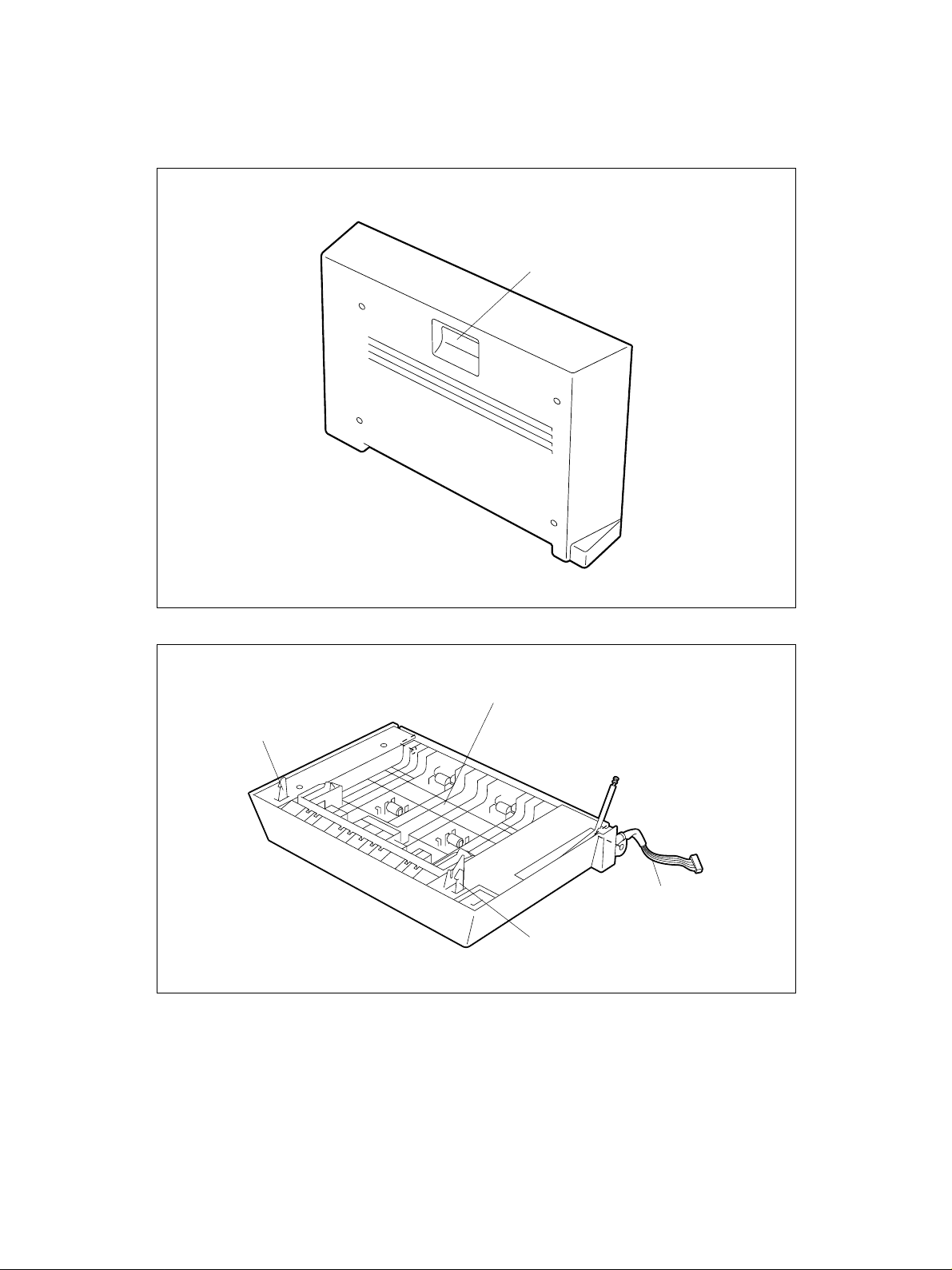
2. OUTLINE
2.1 Names of Various Components
Release lever
ADU release hook F
ADU 02-01-01
ADU paper guide assembly
Connection cable
ADU release hook R
ADU 02-01-02
October 2000 © T OSHIBA TEC 2 - 1 MD-0101 OUTLINE
Page 5
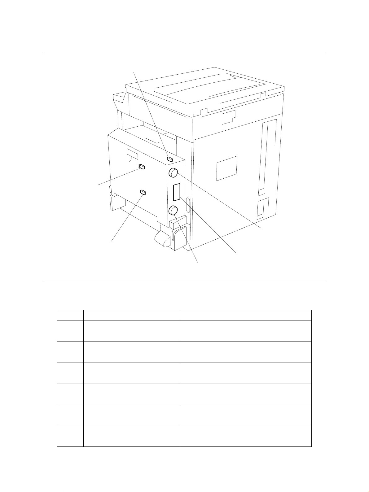
2.2 Layout of Electrical Parts
SW1
SEN2
SEN1
Symbols and functions of various devices
Symbol
SEN1
FED1-SEN
Name
ADU paper jam sensor (Lower)
SEN2
FED2-SEN
ADU paper jam sensor (Upper)
SW1
ADUCOV-SW
ADU cover open switch
M1
FED1-MOT
ADU motor (Lower)
M2
FED2-MOT
M2
ADU (PWA-F-ADU)
M1
ADU 02-02-01
Function
Detects the transport of paper (Lower).
Detects the transport of paper (Upper).
Detection of cover open/close status during jam
processing, etc.
Drives the roller to transport paper (Lower).
Drives the roller to transport paper (Upper).
ADU motor (Upper)
ADU
PWA-F-ADU
ADU PWA
MD-0101 OUTLINE 2 - 2 October 2000 © T OSHIBA TEC
PWA which relays the sensor signals and drives
the motor.
Page 6
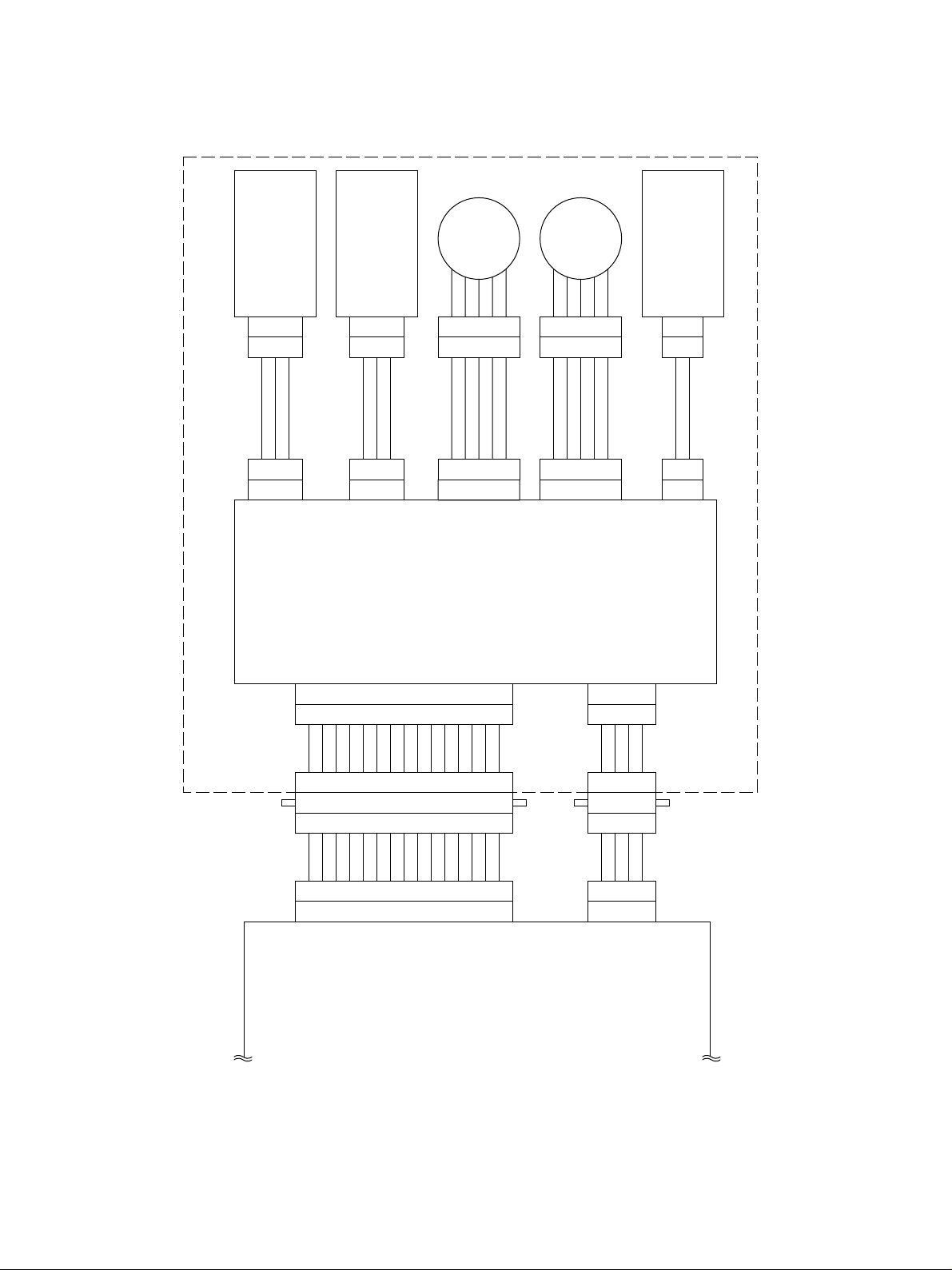
2.3 Harness Connection Diagram
)
Lower
(
ADU paper jam sensor
321
CN312
123
DPF
VCC
GND
CN213
)
Upper
(
ADU paper jam sensor
321
CN328
123
DPF
VCC
GND
CN214
CN215
)
Lower
(
ADU motor
12345
12345
+24V
FDMA
FDMB
FDMC
ADU PWA
FDMD
12345
1
+24V
CN216
)
Upper
(
ADU motor
345
2
EXMA
EXMB
EXMC
EXMD
2
CN311
1
CVSW
CN217
ADU cover open switch
1
2
GND
ADU
1514131211
123456789
CN323
1514131211
123456789
2
FDM-B
FDM-D 1
FDM-C 3
CN203 CN211
987654312
10
987654312
10
4
6
VDD 7
FDM-A
ADUFL
CRT-DOWNA 5
1011121315
10
8
10ADUFU
GND
ADCNT 9
11
ADUCOVSW 11
12
12EXM-A
EXM-C 13
14
14EXM-B
PFC PWA
15EXM-D
CN324
CN204 CN212
432
123
432
123
2
GND
GND 1
1
4
1
4
4
+24V
+24V 3
ADU 02-03-01
October 2000 © T OSHIBA TEC 2 - 3 MD-0101 OUTLINE
Page 7
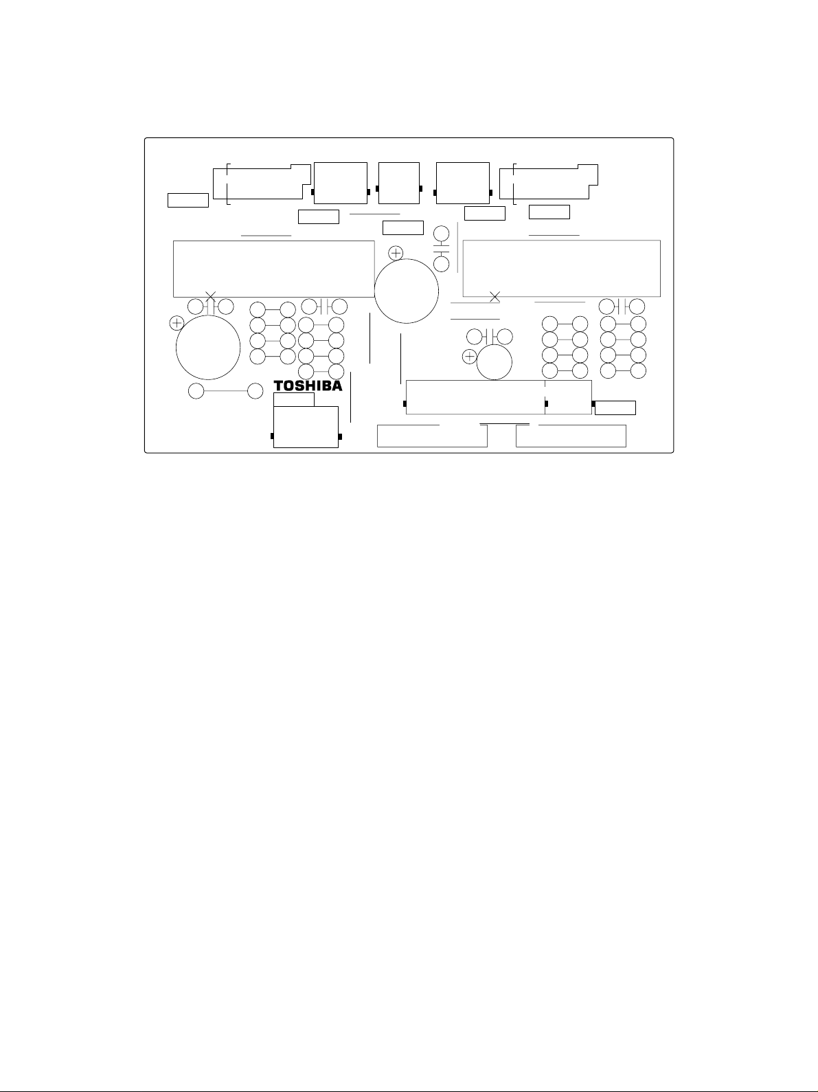
2.4 Board Assembly
6
PWB-F-ADU-520-3 41316208000
CN215
>
PF-WP
JP1
IC1
1
C4
C1
R1
1
3
CN213
<
STK672-210
R2
R4
R3
R5
R9
CN212
41
JP2
C7
R6
R7
R8
1
JP6
JP5
PD
2
CN217
12
C2
JP7
15
31
1
6
CN214
JP3
C5
112
JP10
JP8
C6
JP9
C3
JP11
RV
CN216
JP4
R10
R11
R12
R13
1
STK672-210
1
CN211
IC2
C8
R14
R15
R16
R17
ADU 02-04-01
MD-0101 OUTLINE 2 - 4 October 2000 © T OSHIBA TEC
Page 8

3. OPERATIONAL DESCRIPTION
3.1 General Operation
The ADU is a unit which turns over printed paper . Installation of the unit enab les duplex printing on paper .
No paper can be stacked in the ADU.
3.2 Block Diagram
ADU
PFC
PWA
CN203
+24V
CN204
CN211CN212
CN215
CN216CN213CN214CN217
FDMA-D
EXMA-D
ADU motor (Lower
M
ADU motor (Upper
M
)
)
ADU
PWA
ADUFL
ADUFU
ADUCOVSW
ADU paper jam sensor (Lower
ADU paper jam sensor (Upper
ADU cover open switch
)
)
ADU 03-02-01
The ADU has three sensors and two motors as shown above. One-side-printed paper passes through
the ADU unit to be turned over and returned to the copier. The motor drive circuits (IC1, IC2) only are
installed on the ADU PWA.
The motor signals (EXM-A - D , FDM-A - D) are amplified by IC1 and IC2 and drive the motors. The signal
of each sensor passes through the ADU PWA and is connected as it is to the PFC PWA.
October 2000 © T OSHIBA TEC 3 - 1 MD-0101 OPERATIONAL DESCRIPTION
Page 9

3.3 Detection of Abnormal Status
3.3.1 Cover open/close detection
When the ADU cover open sensor detects the open state of the cov e r, the detection signal is sent to the
copier to stop the transport of paper.
3.3.2 Paper jam detection
When the one-side-printed paper is loaded into the ADU, the ADU paper jam sensors (upper/lower) turn
ON (at “High” lev el) for a fixed time. If the ADU paper jam sensors (upper/lower) do not turn ON or their
ON time is too long, the program will judge it to be paper jamming and stop the operation. The paper
jamming can be cleared by opening the ADU and removing the paper.
MD-0101 OPERATIONAL DESCRIPTION 3 - 2 October 2000 © TOSHIBA TEC
Page 10

3.4 Flow Chart
Start button ON
Scanning of document
NO
All scanning?
YES
Cassette feed
Copy
Transport to ADU
Feed from ADU
Copy
Ejection
Final copy
NO
Change of document
Start button ON
YES
End
ADU 03-04-01
October 2000 © T OSHIBA TEC 3 - 3 MD-0101 OPERATIONAL DESCRIPTION
Page 11

4. MECHANICAL DESCRIPTION
4.1 Paper Feed System
Exit roller
Flow of paper
Copier
ADU paper jam sensor (Upper)
ADU
ADU paper jam sensor (Lower)
ADU 04-01-01
The ADU has one transport path as shown above and paper enters the ADU from the top and comes out
from the bottom. P aper is not stacked in the ADU b ut the ADU only transports the paper by using the two
motors.
Flow of Paper
The flow of paper is as follows:
The one-side-printed paper reversed at the exit unit.
The roller in the exit unit reversely turns to draw the paper into the ADU.
The paper having passed through the ADU is loaded again into the copier from the bottom of the
ADU.
ADU 04-04-02
October 2000 © T OSHIBA TEC 4 - 1 MD-0101 MECHANICAL DESCRIPTION
Page 12

Printing takes place on the back of the paper and the paper is ejected.
Copier side
Flow of paper
ADU motor (Upper)
ADU motor (Lower)
ADU 04-02-01
4.2 Drive System
In the ADU, paper is transported by two pulse motors . The ADU motor (upper) drives the upper roller and
the exit roller of the copier as a result of changing (moving) the gear on the copier side , thereb y drawing
in the one-side-printed paper from the copier.
The paper drawn into the ADU is fed into the copier again from the ADU (bottom) by the roller driven by
the ADU motor (lower). The central roller is driven by the ADU motor (lower) through the belt.
MD-0101 MECHANICAL DESCRIPTION 4 - 2 October 2000 © TOSHIBA TEC
Page 13

5. CIRCUIT DESCRIPTION
5.1 PWA Block Diagram
PFC
PWA
PFC
PWA
ADU PWA
1
2
3
4
5
ADUCOVSW
6
7
8
SG
CN211CN212
+5V
9
10
11
NC
14
15
14
15
+24V
1
+24V
2
3
PG
4
PG
EXM-D
EXM-B
EXM-C
EXM-A
ADUFU
ADCNT
ADUFL
FDM-A
FDM-C
FDM-B
FDM-D
+24V
1
SG
SG
+5V
SG
+5V
+24V
2
3
4
CN216
5
6
1
2
1
2
CN213 CN217CN214
3
1
2
3
1
2
3
4
CN215
5
6
ADU motor
(
)
Upper
ADU cover open switch
ADU paper jam sensor
(
)
Lower
ADU paper jam sensor
(
)
Upper
ADU motor
(
)
Lower
9
A
8
AB
IC2
7
B
Motor driver
6
BB
VREF
R6 R7,R8
9
A
8
AB
7
B
Motor driver
6
BB
VREF11SP
R14 R15,R16
12
IC1
12
+5V
SG
+5V
4
A1
5
A0
2
B1
3
B0
SP
11
4
A1
5
A0
2
B1
3
B0
EXMA
EXMB
EXMC
EXMD
FDMA
FDMB
FDMC
FDMD
ADU 05-01-01
The ADU PWA has the motor driving IC only and the other signals pass through the PWA.
IC1 and IC2 are driver IC’ s for the stepping motors and driv e the ADU motors (upper/lower) on the output
side according to the input signals. IC1 drives the ADU motor (lower), and IC2 the ADU motor (upper).
Vref is the input to determine the value of the current which flows through each motor . The input v oltage
there determines the load (current value) to the motor.
ADCNT is a signal which detects connection of the ADU and connected to GND. When its connector is
attached, the signal goes LOW so that the copier can confirm its connection.
October 2000 © T OSHIBA TEC 5 - 1 MD-0101 CIRCUIT DESCRIPTION
Page 14

5.2 Meaning of Signals
Signal name Part name Functional description Status Note
ADUFL ADU paper jam Detects the transport of High: Paper present Photo sensor
sensor (Lower) paper (Lower)
ADUFU ADU paper jam Detects the transport of High: Paper present Photo sensor
sensor (Upper) paper (Upper)
ADUCOVSW ADU cover Detection of cover High: Open Push switch
open switch open/close status during
jam processing, etc.
EXMA-D ADU motor Drives the roller to transport - PM type
(Upper) paper (Upper) pulse motor
FDMA-D ADU motor Drives the roller to transport - PM type
(Lower) paper (Lower) pulse motor
The ADU cover open s witch is a s witch which detects the open or close state of the cov er . A push switch
is used for the switch. The signal goes LOW when the cover is closed, and HIGH when it is open.
The ADU paper jam sensor (upper/lower) detects the presence or absence of paper in the transf er path.
Photo sensors are used for the sensors. When paper passes, the sensor arm in the transfer path is
pressed to turn on the sensor.
The ADU motor (lower) and ADU motor (upper) are 2-phase excitation PM type pulse motors (stepping
motors) and operate according to the drive signals from the driver IC’s (IC1, IC2).
MD-0101 CIRCUIT DESCRIPTION 5 - 2 October 2000 © T OSHIBA TEC
Page 15

5.3 Timing Char t
19.51s (15.49s)
17.14s (12.62s)
14.57s (10.72s)
14.59s (10.74s)
11.83s (8.79s)
5.67s (4.01s)
12.17s (8.95s)
10.96s (8.01s)
5.96s (4.30s)
5.84s (4.13s)
10.66s (7.79s)
8.07s (5.87s)
12.08s (8.97s)
11.52s (8.57s)
10.96s (8.01s)
8.43s (6.13s)
13.16s (9.69s)
9.74s (7.10s)
The values are data (reference values) applicable when the A4 size paper is used.
The value in brackets is for the DP2500 machine.
3.12s (2.18s)
3.11s (2.17s)
Feed sensor
October 2000 © T OSHIBA TEC 5 - 3 MD-0101 CIRCUIT DESCRIPTION
Exit sensor
3.13s (2.19s)
ADU motor
(Upper)
ADU paper
jam sensor
(Upper)
ADU motor
(Lower)
ADU paper
jam sensor
(Lower)
ADU 05-03-01
Page 16

6. DISASSEMBLY AND REPLACEMENT
[A] ADU hinge cover F/R
1. Remove 2 screws and detach ADU hinge co ver
F.
2. Remove 2 screws and detach ADU hinge co ver
R.
[B] ADU paper guide assembly
Screw
Screw
ADU hinge
cover R
Screw
ADU hinge cover F
223
Fig. 6-1
Screw
224
Fig. 6-2
1. Pull ADU release lev er to release one hook and
open ADU.
2. Release 2 hooks and remove ADU paper guide
assembly.
ADU release lever
ADU
225
Fig. 6-3
ADU paper guide assembly Hook
226
Fig. 6-4
October 2000 © TOSHIBA TEC 6 - 1 MD-0101 DISASSEMBLY AND REPLACEMENT
Page 17

[C] ADU
1. Detach ADU hinge cover F. (See Fig. 6-1)
2. Detach ADU hinge cover R. (See Fig. 6-2)
3. Remove one screw and detach harness fixing
plate.
4. Remove one screw , detach the g round wire and
the connector.
Screw
Harness fixing plate
227-1
Fig. 6-5
Screw
Connector
5. Remove stopper from ADU hinge F.
6. Open ADU, remove one screw, and remove
plate A.
Ground wire
Snap pin
Fig. 6-6
ADU hinge F
Fig. 6-7
Screw
227-2
228
Plate A
ADU
229
Fig. 6-8
MD-0101 DISASSEMBLY AND REPLACEMENT 6 - 2 October 2000 © TOSHIBA TEC
Page 18

7. Release one hook and detach the wire.
8. Release 2 hinges and remove ADU.
[D] ADU cover
1. Detach ADU hinge cover F. (See Fig. 6-1)
2. Detach ADU hinge cover R. (See Fig. 6-2)
3. Remove ADU. (See Fig. 6-5 to 6-9)
4. Remove 2 scre ws, release one hook and wire ,
and detach ADU hook cover R.
5. Release 2 hooks, detach one connector, and
remove ADU cover open sensor.
ADU
ADU hook cover R
Hook
ADU cover
open sensor
Wire
230
Fig. 6-9
Screw
Wire
231
Fig. 6-10
Connector
Hook
232
Fig. 6-11
6. Remove 4 scre ws and detach ADU cover.
Screw
Screw
ADU cover
233
Fig. 6-12
October 2000 © TOSHIBA TEC 6 - 3 MD-0101 DISASSEMBLY AND REPLACEMENT
Page 19

[E] ADU PWA
1. Detach ADU hinge cover F. (See Fig. 6-1)
2. Detach ADU hinge cover R. (See Fig. 6-2)
3. Remove ADU. (See Fig. 6-5 to 6-9)
4. Detach ADU cover. (See Fig. 6-10 to 6-12)
5. Remove 4 scre ws, release the harness from the
clamp, and detach PWA cover.
6. Detach all the connectors from ADU PWA, re-
lease 4 locking supports, and remove ADU
PWA.
Screw
Screw
Locking support
Clamp
Fig. 6-13
Clamp
PWA cover
234
ADU PWA
[F] ADU motor
1. Detach ADU hinge cover F. (See Fig. 6-1)
2. Detach ADU hinge cover R. (See Fig. 6-2)
3. Remove ADU. (See Fig. 6-5 to 6-9)
4. Detach ADU cover. (See Fig. 6-10 to 6-12)
5. Detach one connector from ADU PWA (CN216),
remove 2 screws, remove ADU motor by sliding in the direction of the arrow .
Note: Apply 0.1g of GREASE (X5-6020) to the
gear tooth surface.
ADU motor
Screw
Fig. 6-14
CN216
Connector
Fig. 6-15
235
ADU motor
236-1
MD-0101 DISASSEMBLY AND REPLACEMENT 6 - 4 October 2000 © TOSHIBA TEC
Page 20

[G] ADU feed roller shaft upper/clutch 08S018-06CL
1. Detach ADU hinge cover F. (See Fig. 6-1)
2. Detach ADU hinge cover R. (See Fig. 6-2)
3. Remove ADU paper guide assemb ly.
(See Fig. 6-3 and 6-4)
4. Remove ADU. (See Fig. 6-5 to 6-9)
5. Detach ADU cover. (See Fig. 6-10 to 6-12)
6. Detach PWB cover. (See Fig. 6-13)
7. Remove 2 scre ws and remove ADU release le-
ver.
8. Release Spring, remove one screw , and remov e
ADU release hook R.
Screw
Spring
ADU release lever
Fig. 6-16
Screw
Fig. 6-17
236-2
ADU release
hook R
237
9. Detach one connector from ADU PWA (CN216).
10. Remove 4 screws, release one clamp, and re-
move ADU motor brac k et upper.
ADU PWB
Screw
CN216
Harness
Screw
ADU motor bracket upper
Fig. 6-18
Clamp
238
October 2000 © TOSHIBA TEC 6 - 5 MD-0101 DISASSEMBLY AND REPLACEMENT
Page 21

11. Detach the E-ring, and remove clutch 08S018-
06CL and bushing.
E-ring
12. Detach stop ring, and remove bushing and ADU
feed roller shaft upper.
[H] ADU feed roller shaft middle
1. Detach ADU hinge cover F. (See Fig. 6-1)
2. Detach ADU hinge cover R. (See Fig. 6-2)
3. Remove ADU paper guide assemb ly.
(See Fig. 6-3 and 6-4)
4. Remove ADU. (See Fig. 6-5 to 6-9)
5. Detach ADU cover. (See Fig. 6-10 to 6-12)
6. Detach PW A co ver. (See Fig. 6-13)
7. Remove ADU PWA. (See Fig. 6-14)
8. Detach stop ring and remove pulle y and timing
Clutch 08S018-06CL
Pulley
Pin
Bushing
Fig. 6-19
Fig. 6-20
Pulley
Fig. 6-21
ADU feed roller
shaft upper
Bushing
Stop ring
Pin
Stop ring
Timing belt
Stop ring
239
240
Pulley
241
belt.
Note: Be sure to insert the pins when attaching.
MD-0101 DISASSEMBLY AND REPLACEMENT 6 - 6 October 2000 © TOSHIBA TEC
Page 22

9. Detach stop ring, remove 2 bushings, and re-
move ADU f eed roller shaft middle.
[I] ADU feed roller shaft lower/clutch 08S018-06CL
1. Detach ADU hinge cover F. (See Fig. 6-1)
2. Detach ADU hinge cover R. (See Fig. 6-2)
3. Remove ADU paper guide assemb ly.
(See Fig. 6-3 and 6-4)
4. Remove ADU. (See Fig. 6-5 to 6-9)
5. Detach ADU cover. (See Fig. 6-10 to 6-12)
Stop ring
CN215
ADU feed roller
shaft middle
Bushing
Bushing
242
Fig. 6-22
ADU PWA
ADU motor
bracket lower
6. Detach PWB cover. (See Fig. 6-13)
7. Remove timing belt. (See Fig. 6-21)
8. Detach one connector from ADU PWA (CN215).
9. Remove 4 screws, release one clamp, and re-
move ADU motor brac ket lower.
10. Detach the E-ring, remove clutch 08S018-06CL
and 2 bushings, and remove ADU feed roller
shaft lower .
Clamp
Harness
Clutch 08S018-06CL
Bushing
E-ring
Connector
Fig. 6-23
ADU feed roller
shaft lower
ADU feed roller
shaft lower
Fig. 6-24
Screw
243
Bushing
244
October 2000 © TOSHIBA TEC 6 - 7 MD-0101 DISASSEMBLY AND REPLACEMENT
 Loading...