

Engineering
Data Book
E14-361
Notice: Toshiba is committed to continuously improving its products to ensure the highest
quality and reliability standards, and to meet local regulations and market requirements. All
features and specifications are subject to change without prior notice.
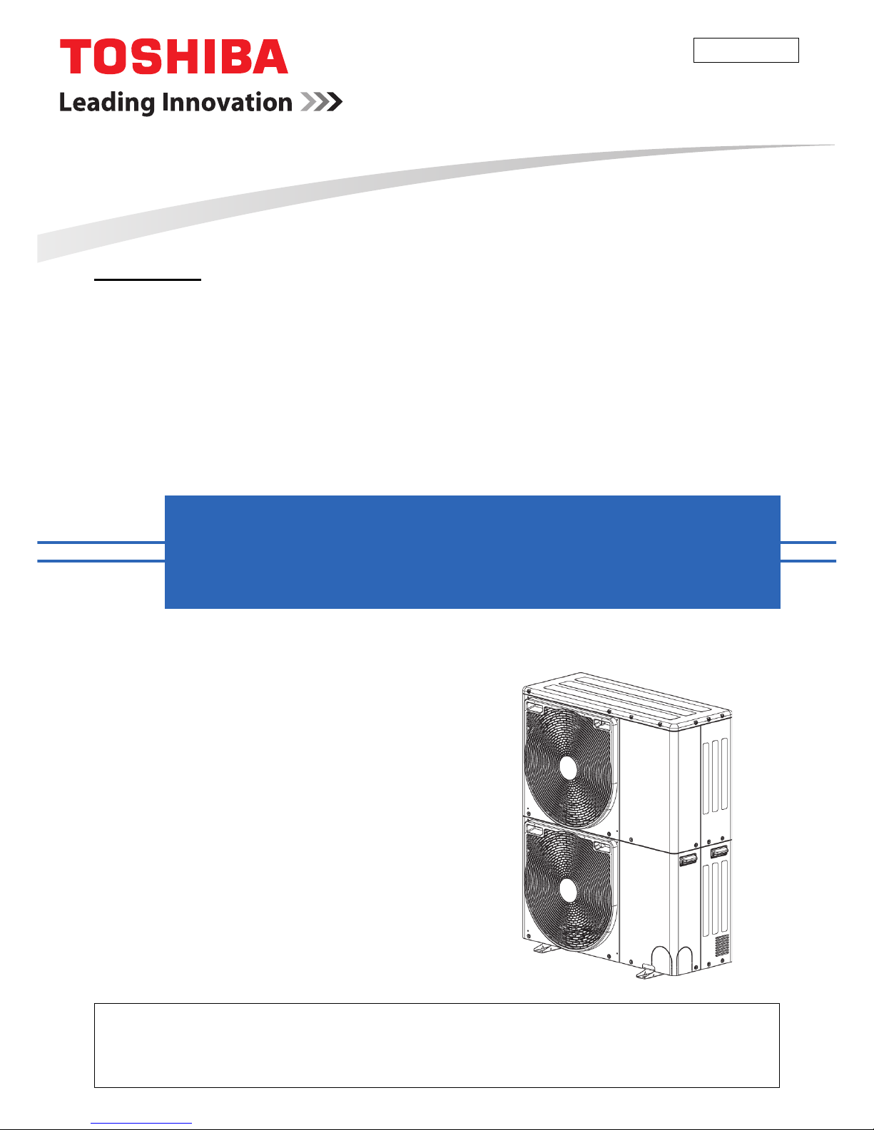
Model name:
MCY-MHP0404HT-E
MCY-MHP0504HT-E
MCY-MHP0604HT-E
Outdoor units
Side blow VRF
1
Side blow VRF Data book
Safety caution............................................................................................................2
1 System overview.................. ......................................................................................5
1-1. Allocation standard of model name..................................................................5
1-2. Summary of system equipments......................................................................5
2 Equipment selection procedure ...............................................................................10
2-1. Selection flow chart ........................................................................................10
2-2. Combination conditions for indoor unit and outdoor unit................................11
2-3. Cooling / heating capacity characteristics ......................................................12
2-4. Operational temperature range ......................................................................15
3 Refrigerant piping design.........................................................................................16
3-1. Free branching system...................................................................................16
3-2. Allowable length / height difference of refrigerant piping................................17
3-3. Selection of refrigerant piping.........................................................................18
3-4. Allowable length / height difference of refrigerant piping with PMV Kit ..........19
3-5. Selection of refrigerant piping with PMV Kit ...................................................20
3-6. Charging requirement with additional refrigerant ...........................................21
4 Wiring design...........................................................................................................22
4-1. General...........................................................................................................22
4-2. Electrical wiring design...................................................................................22
4-3. Outdoor unit power supply..............................................................................22
4-4. Indoor unit power supply ................................................................................23
4-5. Design of control wiring..................................................................................26
5 Outdoor unit.............................................................................................................28
5-1. Specifications .................................................................................................28
5-2. Dimensional drawing......................................................................................29
5-3. Branch header / branch joint ..........................................................................30
5-4. Refrigerant cycle diagram ..............................................................................31
5-5. Wiring diagram ................................................................. ..............................32
5-6. Connecting diagram .......................................................................................33
5-7. Optional printed circuit board (PCB) of out
door unit
.......................................34
5-8. Part load performance....................................................................................39
5-9. Sound pressure level data..............................................................................42
5-10. PMV Kit ..........................................................................................................44
Contents
2
Side blow VRF Data book
Safety caution
• Before use, read carefully through the “Safety caution” section to ensure correct operation.
• The important contents concerned to the safety are described in the “Safety cautions”.
Be sure to keep them. For Indications and their meanings, see the following description.
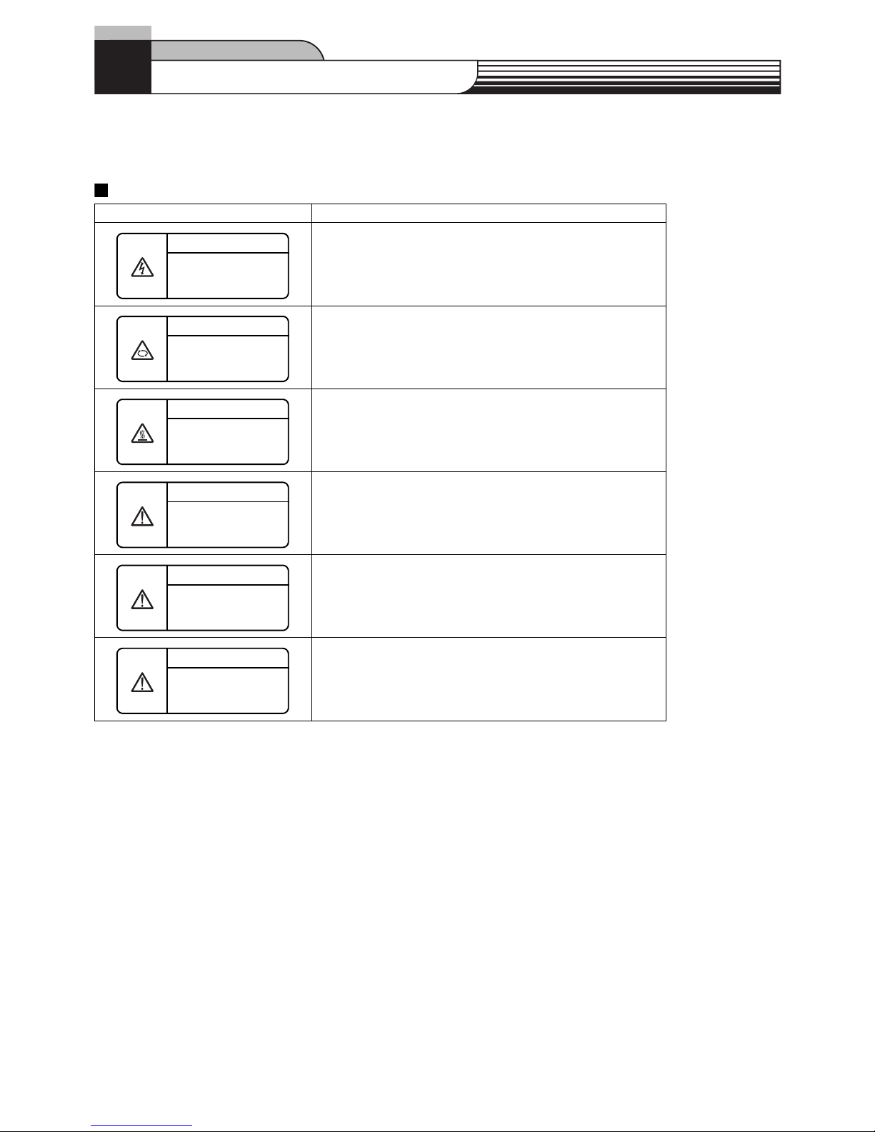
Warning Indications on the Air Conditioner Unit
Warning indication Description
WARNING
ELECTRICAL SHOCK HAZARD
Disconnect all remote electric power supplies before servicing.
WARNING
Moving parts.
Do not operate unit with grille removed.
Stop the unit before the servicing.
CAUTION
High temperature parts.
You might get burned when removing this panel.
CAUTION
Do not touch the aluminium fins of the unit.
Doing so may result in injury.
CAUTION
BURST HAZARD
Open the service valves before the operation, otherwise there might be the
burst.
CAUTION
Do not climb onto the fan guard.
Doing so may result in injury.
WARNING
ELECTRICAL SHOCK HAZARD
Disconnect all remote
electric power supplies
WARNING
Moving parts.
Do not operate unit with
grille removed.
CAUTION
High temperature parts.
You might get burned when
removing this panel.
CAUTION
Do not touch the aluminum
fins of the unit.
Doing so may result in injury.
CAUTION
BURST HAZARD
Open the service valves
before the operation,
CAUTION
Do not climb onto the fan
guard.
Doing so may result in
3
Safety caution
Explanation of indications
WARNING
Indicates possibilities that a death or serious injury of personnel is caused by an incorrect handling.
CAUTION
Indicates contents that an injury (*1) or property damage (*2) only may be caused when an incorrect work has been executed.
*1: “In jury” means a hurt, a burn, or an electric shock which does not require hospitalization or a long-term going to the hospital.
*2: “Property damage means an enlarged damage concerned to property, or breakage of materials.
• After installation work has finished, check there is no trouble by a test operation, and explain using method and
maintenance method to the customers based on the Owner’s Manua l.
Please ask the customers to keep this Installation Manual together with the Owner’s Manual.
WARNING
Ask a shop or a professional dealer to instal l the air conditioner.
If you will install by yourself, a fire, an electric shock, or water leak is caused.
Take measures so that the refri gerant does not exceed the limit concentration even if it leaks whe n inst alling the air conditioner
in a small room.
For the measures not to exceed the limit of concentration, contact the dealer. If the refrigerant leaks and it exceeds the limit of
concentration, an accident of oxygen shortage is caused.
Install the air conditioner at a place which is satisfactorily bearable to weight.
If strength is insufficient, the unit may fall down resulting in human injury.
Perform a specified installation work against a strong wind such as typhoon or earthquake.
If the air conditioner is imperfectly installed, an accident by falling or dropping may be caused.
If refrigerant gas leaks during installation work, ventilate the room.
If the leaked refrigerant gas approaches to fire, noxious gas may generate.
After installation work, confirm that refrigerant gas does not leak.
If refrigerant gas leaks in the room, and approaches t o f ire su ch as f an heate r, stove or kitchen range, generation of noxiou s g as ma y b e
caused.
Never recover refrigerant in the outdoor unit.
Be sure to use a refrigerant recovery device to recover refrigerant in reinstallation or repair work.
Recovery of refrigerant in the outdoor unit is unavailable; otherwise a serious accident such as crack or human injury is caused.
A person qualified for the electric work sh ou ld deal with the electric construction conforming to the regulations of the local
electric company and the Installation Manual. Be sure to use the exclusive circuit.
If there is capacity shortage of the power supply circuit or incomplete installation, a fire or an electric shock is caused.
For cabling, use the specified cables and connect them securely so that external force of cable does not transmit to the
terminal connecting section.
If connection or fixing is incomplete, a fire, etc. may be caused.
Be sure to connect earth wire.
Do not connect earth wire to gas pipe, water pipe, lightning rod, nor earth wire of telephone.
If grounding is incomplete, an electric shock is caused.
CAUTION
Do not install the air conditioner at a place where combustible gas may leak.
If gas leaks and is collected at surrounding the unit, the production of fire may be caused.
Be sure to attach an earth leakage breaker; otherwise an electric shock may be caused.
Using a torque wrench, tighten the flare nut in the specified method.
If the flare nut is exceedingly tightened, the flare nut is broken and a refrigerant leakage may be caused after a long time has passed.
4
Safety caution
WARNINGS ON REFRIGERANT LEAKAGE
Check of Concentration Limit
The room in which the air conditioner is to be
installed requires a design that in the event of
refrigerant gas leaking out, its concentration will not
exceed a set limit.
The refrigerant R410A which is used in the air
conditioner is safe, without the toxicity or combustibility
of ammonia, and is not restricted by laws to be imposed
which protect the ozone layer. However, since it
contains more than air, it poses the risk of suffocation if
its concentration should rise excessively.
Suffocation from leakage of R410A is almost
nonexistent. With the recent increase in the number of
high concentration buildings, however , the installation of
multi air conditioner systems is on the increase because
of the need for effective use of floor space, individual
control, energy conservation by curtailing heat and
carrying power etc.
Most importantly , the multi a ir conditioner system is abl e
to replenish a large amount of refrigerant compared
with conventional individual air conditioners. If a single
unit of the multi conditioner system is to be
installed in a small room, select a suitable model and
installation procedure so that if the refrigerant
accidentally leaks out, its concentration does not reach
the limit (and in the event of an emergency, measures
can be made before injury can occur).
In a room where the concentration may exceed the limit,
create an opening with adjacent rooms, or install
mechanical ventilation combined with a gas leak
detection device.
The concentration is as given below.
≤ Concentration limit (kg/m
3
)
The concentration limit of R410A which is used in multi
air conditioners is 0.3 kg/m
3
.
NOTE 1:
If there are 2 or more refrigerating systems in a single
refrigerating device, the amounts of refrigerant should
be as charged in each independent device.
For the amount of charge in this example:
The possible amount of leaked refrigerant gas in
rooms A, B and C is 10 kg.
The possible amount of leaked refrigerant gas in
rooms D, E and F is 15 kg.
NOTE 2:
The standards for minimum room volume are as fo llows.
(1) No partition (shaded portion)
(2) When there is an effective opening with the adjacent
room for ventilation of leaking refrigerant gas
(opening without a door, or an opening 0.15 % or
larger than the respective floor spaces at the top or
bottom of the door).
(3) If an indoor unit is installed in each partitioned room
and the refrigerant tubing is interconnected, the
smallest room of course becomes the object. But
when a mechanical ventilation is installed
interlocked with a gas leakage detector in the
smallest room where the density limit is exceeded,
the volume of the next smallest room becomes the
object.
NOTE 3:
The minimum indoor floor area compared with the
amount of refrigerant is roughly as follows: (When the
ceiling is 2.7 m high)
Total amount of refrigerant (kg)
Min. volume of the indoor unit installed room (m
3
)
Outdoor unit
e.g.,
charged amount (15 kg)
e.g., charged
amount (10 kg)
Indoor unit
Room A Room B Room C R oom D Room E Room F
Important
Outdoor unit
Refrigerant piping
Indoor unit
Refrigerant piping
Outdoor unit
Indoor unit
Mechanical ventilation device - Gas leak detector
Very
small
room
Small
room
Medium
room
Large room
0
5
10
10 20 30
15
20
25
30
35
40
kg
m²
Min. indoor floor area
Range below the
density limit of 0.3
kg/m
3
(countermeasures
not needed)
Range above the
density limit of 0.3
kg/m
3
(countermeasures
needed)
Total amount of refrigerant
5
Side blow VRF Data book
1 System overview
1-1. Allocation standard of model name
1-2. Summary of system equipments
1-2-1. Outdoor units
*1 Rated conditions
Cooling : Indoor air temperature 27 °C DB / 19 °C WB. Outdoor air temperature 35 °C DB.
Heating : Indoor air temperature 20 °C DB. Outdoor air temperature 7 °C DB / 6 °C WB.
Corresponding HP
Inverter unit
4HP 5HP 6HP
Model name MCY-MHP0404HT-E MCY-MHP0504HT-E MCY-MHP0604HT-E
Cooling capacity (kW)*1 12.1 14.0 15.5
Heating capacity (kW)*1 12.5 16.0 18.0
No. of connectable indoor units 6 6 6
MCY
_
MH T J
HP
_
E
E : Europe, corresponding to European standard model
J : Anti-corrosion heavy protection
T : Capacity variable unit
H : Heat pump
Development series number
Capacity
Hangzhi products R410A
M : Single module unit
Multi Compact Type
6
1 System overview
1-2-2. Indoor units
Type Appearance Model name Capacity rank Capacity code
Cooling
capacity (kW)
Heating
capacity (kW)
PMV Kit
4-way Air Discharge
Cassette Type
MMU-AP0092H 009 type 1.00 2.8 3.2 -
MMU-AP0122H 012 type 1.25 3.6 4.0 -
MMU-AP0152H 015 type 1.70 4.5 5.0 -
MMU-AP0182H 018 type 2.00 5.6 6.3 -
MMU-AP0242H 024 type 2.50 7.1 8.0 -
MMU-AP0272H 027 type 3.00 8.0 9.0 -
MMU-AP0302H 030 type 3.20 9.0 10.0 -
MMU-AP0362H 036 type 4.00 11.2 12.5 -
MMU-AP0482H 048 type 5.00 14.0 16.0 -
MMU-AP0562H 056 type 6.00 16.0 18.0 -
MMU-AP0094HP-E 009 type 1.00 2.8 3.2 -
MMU-AP0124HP-E 012 type 1.25 3.6 4.0 -
MMU-AP0154HP-E 015 type 1.70 4.5 5.0 -
MMU-AP0184HP-E 018 type 2.00 5.6 6.3 -
MMU-AP0244HP-E 024 type 2.50 7.1 8.0 -
MMU-AP0274HP-E 027 type 3.00 8.0 9.0 -
MMU-AP0304HP-E 030 type 3.20 9.0 10.0 -
MMU-AP0364HP-E 036 type 4.00 11.2 12.5 -
MMU-AP0484HP-E 048 type 5.00 14.0 16.0 -
MMU-AP0564HP-E 056 type 6.00 16.0 18.0 -
Compact 4-way
Cassette (600 × 600)
Type
MMU-AP0054MH-E 005 type 0.60 1.7 1.9 Available
MMU-AP0074MH-E 007 type 0.80 2.2 2.5 Available
MMU-AP0094MH-E 009 type 1.00 2.8 3.2 Available
MMU-AP0124MH-E 012 type 1.25 3.6 4.0 Available
MMU-AP0154MH-E 015 type 1.70 4.5 5.0 Available
MMU-AP0184MH-E 018 type 2.00 5.6 6.3 Available
2-way Air Discharge
Cassette Type
MMU-AP0072WH 007 type 0.80 2.2 2.5 -
MMU-AP0092WH 009 type 1.00 2.8 3.2 -
MMU-AP0122WH 012 type 1.25 3.6 4.0 -
MMU-AP0152WH 015 type 1.70 4.5 5.0 -
MMU-AP0182WH 018 type 2.00 5.6 6.3 -
MMU-AP0242WH 024 type 2.50 7.1 8.0 -
MMU-AP0272WH 027 type 3.00 8.0 9.0 -
MMU-AP0302WH 030 type 3.20 9.0 10.0 -
MMU-AP0362WH 036 type 4.00 11.2 12.5 -
MMU-AP0482WH 048 type 5.00 14.0 16.0 -
MMU-AP0562WH 056 type 6.00 16.0 18.0 -
1-way Air Discharge
Cassette Type
MMU-AP0074YH-E 007 type 0.80 2.2 2.5 Available
MMU-AP0094YH-E 009 type 1.00 2.8 3.2 Available
MMU-AP0124YH-E 012 type 1.25 3.6 4.0 Available
MMU-AP0154SH-E 015 type 1.70 4.5 5.0 Available
MMU-AP0184SH-E 018 type 2.00 5.6 6.3 Available
MMU-AP0244SH-E 024 type 2.50 7.1 8.0 Available
Concealed Duct
Type
MMD-AP0076BHP-E 007 type 0.80 2.2 2.5 Available
MMD-AP0096BHP-E 009 type 1.00 2.8 3.2 Available
MMD-AP0126BHP-E 012 type 1.25 3.6 4.0 Available
MMD-AP0156BHP-E 015 type 1.70 4.5 5.0 Available
MMD-AP0186BHP-E 018 type 2.00 5.6 6.3 Available
MMD-AP0246BHP-E 024 type 2.50 7.1 8.0 Available
MMD-AP0276BHP-E 027 type 3.00 8.0 9.0 Available
MMD-AP0306BHP-E 030 type 3.20 9.0 10.0 Available
MMD-AP0366BHP-E 036 type 4.00 11.2 12.5 Available
MMD-AP0486BHP-E 048 type 5.00 14.0 16.0 Available
MMD-AP0566BHP-E 056 type 6.00 16.0 18.0 Available
Concealed Duct
High Static
Pressure Type
MMD-AP0184H-E 018 type 2.00 5.6 6.3 -
MMD-AP0244H-E 024 type 2.50 7.1 8.0 -
MMD-AP0274H-E 027 type 3.00 8.0 9.0 -
MMD-AP0364H-E 036 type 4.00 11.2 10.0 -
MMD-AP0484H-E 048 type 5.00 14.0 16.0 -
7
1 System overview
Slim Duct Type
MMD-AP0054SPH-E 005 type 0.60 1.7 1.9 Available
MMD-AP0074SPH-E 007 type 0.80 2.2 2.5 Available
MMD-AP0094SPH-E 009 type 1.00 2.8 3.2 Available
MMD-AP0124SPH-E 012 type 1.25 3.6 4.0 Available
MMD-AP0154SPH-E 015 type 1.70 4.5 5.0 Available
MMD-AP0184SPH-E 018 type 2.00 5.6 6.3 Available
MMD-AP0244SPH-E 024 type 2.50 7.1 8.0 Available
MMD-AP0274SPH-E 027 type 3.00 8.0 9.0 Available
Ceiling Type
MMC-AP0154H-E 015 type 1.70 4.5 5.0 -
MMC-AP0184H-E 018 type 2.00 5.6 6.3 -
MMC-AP0244H-E 024 type 2.50 7.1 8.0 -
MMC-AP0274H-E 027 type 3.00 8.0 9.0 -
MMC-AP0364H-E 036 type 4.00 11.2 12.5 -
MMC-AP0484H-E 048 type 5.00 14.0 16.0 -
MMC-AP0157HP-E 015 type 1.70 4.5 5.0 -
MMC-AP0187HP-E 018 type 2.00 5.6 6.3 -
MMC-AP0247HP-E 024 type 2.50 7.1 8.0 -
MMC-AP0277HP-E 027 type 3.00 8.0 9.0 -
MMC-AP0367HP-E 036 type 4.00 11.2 12.5 -
MMC-AP0487HP-E 048 type 5.00 14.0 16.0 -
MMC-AP0567HP-E 056 type 6.00 16.0 18.0 -
High-wall Type
3 series
MMK-AP0073H 007 type 0.80 2.2 2.5 Available
MMK-AP0093H 009 type 1.00 2.8 3.2 Available
MMK-AP0123H 012 type 1.25 3.6 4.0 Available
MMK-AP0153H 015 type 1.70 4.5 5.0 Available
MMK-AP0183H 018 type 2.00 5.6 6.3 Available
MMK-AP0243H 024 type 2.50 7.1 8.0 Available
High-wall Type
4 series
MMK-AP0074MH-E 007 type 0.80 2.2 2.5 Available
MMK-AP0094MH-E 009 type 1.00 2.8 3.2 Available
MMK-AP0124MH-E 012 type 1.25 3.6 4.0 Available
Floor Standing
Concealed Type
MML-AP0074BH-E 007 type 0.80 2.2 2.5 -
MML-AP0094BH-E 009 type 1.00 2.8 3.2 -
MML-AP0124BH-E 012 type 1.25 3.6 4.0 -
MML-AP0154BH-E 015 type 1.70 4.5 5.0 -
MML-AP0184BH-E 018 type 2.00 5.6 6.3 -
MML-AP0244BH-E 024 type 2.50 7.1 8.0 -
Floor Standing
Cabinet Type
MML-AP0074H-E 007 type 0.80 2.2 2.5 Available
MML-AP0094H-E 009 type 1.00 2.8 3.2 Available
MML-AP0124H-E 012 type 1.25 3.6 4.0 Available
MML-AP0154H-E 015 type 1.70 4.5 5.0 Available
MML-AP0184H-E 018 type 2.00 5.6 6.3 Available
MML-AP0244H-E 024 type 2.50 7.1 8.0 Available
Floor Standing Type
MMF-AP0154H-E 015 type 1.70 4.5 5.0 -
MMF-AP0184H-E 018 type 2.00 5.6 6.3 -
MMF-AP0244H-E 024 type 2.50 7.1 8.0 -
MMF-AP0274H-E 027 type 3.00 8.0 9.0 -
MMF-AP0364H-E 036 type 4.00 11.2 10.0 -
MMF-AP0484H-E 048 type 5.00 14.0 16.0 -
MMF-AP0564H-E 056 type 6.00 16.0 18.0 -
Console Type
MML-AP0074NH-E 007 type 0.80 2.2 2.5 Available
MML-AP0094NH-E 009 type 1.00 2.8 3.2 Available
MML-AP0124NH-E 012 type 1.25 3.6 4.0 Available
MML-AP0154NH-E 015 type 1.70 4.5 5.0 Available
MML-AP0184NH-E 018 type 2.00 5.6 6.3 Available
Type Appearance Model name Capacity rank Capacity code
Cooling
capacity (kW)
Heating
capacity (kW)
PMV Kit
8
1 System overview
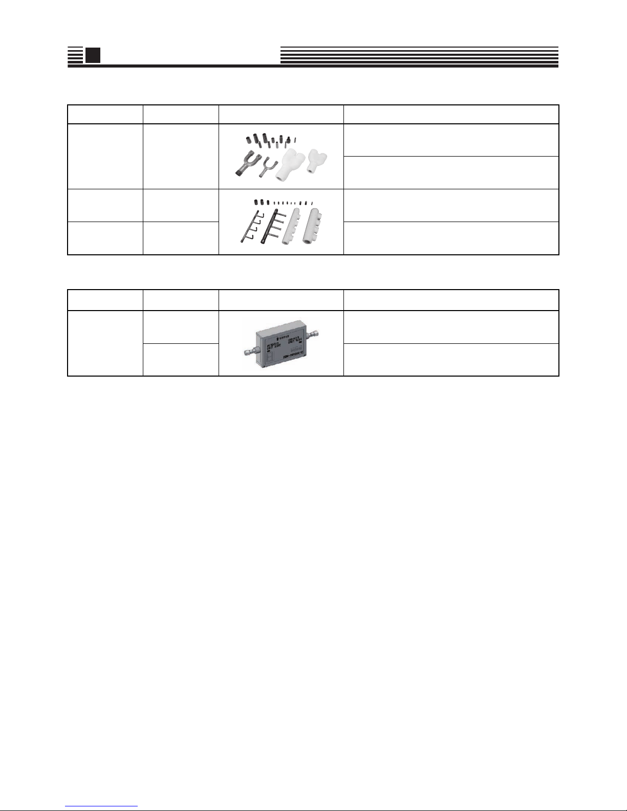
1-2-3. Branching joints and headers
1-2-4. PMV Kits
Name Model name Appearance Remarks
Y -shape branching
joint
RBM-BY55E
4-branching
header
RBM-HY1043E
8-branching
header
RBM-HY1083E
Name Model name Appearance Remarks
PMV Kits
RBM-PMV0362E
RBM-PMV0902E

9
1 System overview
1-2-5. Remote controllers
1-2-6. Optional PCB of outdoor unit
1-2-7. Controls
Name Model Name Remarks
Wired remote controller RBC-AMT32E
Simple wired remote controller RBC-AS41E2
Wireless remote controller kit
RBC-AX32U(W)-E
RBC-AX32U(WS)-E
For 4-way Air Discharge Cassette
RBC-AX32CE2
For Under Ceiling 4series, 1-way Air Discharge
Cassette SH
TCB-AX33CE
For Under Ceiling 7series, Under Ceiling and 1-way Air
Discharge Cassette SH 4series
TCB-AX32E2
For Compact 4-way Cassette, 1-way Air Discharge
Cassette YH, Concealed Duct Standard, Slim Duct,
Floor Standing Cabinet, Floor Standing
RBC-AX23UW(W)-E For 2-way Air Discharge Casette
ON-OFF controller TCB-CC163TLE2
Central remote controller
TCB-SC642TLE2
BMS-CM1280TLE
Schedule timer TCB-EXS21TLE
Remote controller with schedule timer
(7-day timer function)
RBC-AMS41E
Lite-Vision plus Remote Controller RBC-AMS51E-EN/ES
-EN : English, Italian, Polish, Greece, Russian, Turkish
-ES : English, Spanish, Portuguese, French, Dutch,
German
Name Model Name Remarks
Power peak-cut control board TCB-PCDM4E
External master ON/OFF control board TCB-PCMO4E
Output control board TCB-PCIN4E
Name Model Name Remarks
Touch Screen Controller
BMS-TP0641ACE
BMS-TP5121ACE
BMS-TP0641PWE
BMS-TP5121PWE
ACE:Without energy monitoring function
PWE:With energy monitoring function
0641:Maxmimum 64 indoor units connectable
5121:Maximum 512 indoor units connectable
Smart BMS manager BMS-SM1280HTLE
Smart BMS manager with data
analyzer
BMS-SM1280ETLE
WEB Based Controller
BMS-WB2561PWE
BMS-WB01GTE
TCS-NET Relay Interface BMS-IFLSV4E
Energy Monitoring Relay Interface BMS-IFWH5E
Digital I/O Relay Interface BMS-IFDD03E
LonWorks LN Interface TCB-IFLN642TLE
BACnet Server
BMS-LSV9E
BMS-STBN10E
Modbus Interface TCB-IFMB641TLE
Analog Interface TCB-IFCB640TLE
10
Side blow VRF Data book
2
Equipment selection procedure
2-1. Selection flow chart
end
YES
NO
YES
NO
' Increase of indoor unit
capacity at object room against
air-conditioning load
Preliminary selection of indoor units in the standard capacity no less than
air-conditioning load at each room.
Calculate corrected capacity A of each indoor unit by correcting of indoor
temperature for the standard capacity of each indoor unit.(Refer to Chart [1])
Preliminary selection of outdoor unit in the standard capacity no less than
total values of corrected capacity A in indoor units. And check both connectable indoor units number and the outdoor unit diversity(Connected ratio of
indoor units to outdoor units) for the specifications.
Calculate corrected capacity B of each indoor unit by following 2 steps.
Step1:Find the correction value of "Connecting pipe length and lift -" by both
the longest length and the largest height. (Refer to Chart [3])
Step2:Calculate by multiplying the value of step1 by corrected capacity A.
Calculate corrected capacity C of each indoor unit by multiplying the total
corrected capacity of outdoor unit at by proportional division of each indoor
unit standard capacity for total standard capacity of all indoor units.
Find correction values of below items for the standard capacity of outdoor
unit selected at or '.
Then determination of total corrected capacity of the selected outdoor unit by
all multiplying.
-Correction of indoor temperature condition(Refer to Chart [1])
-Correction of outdoor temperature condition(Refer to Chart [2])
-Correction of connecting pipe length and lift between indoor and outdoor
units by both the longest length and the largest height (Refer to Chart [3])
-Correction of outdoor unit diversity (Refer to Chart [4])
-Correction of frost condition on outdoor heat exchanger when in heating
(Refer to Chart [5])
Determination of indoor air-conditioning load at each room.
Corrected capacity C of indoor
unit >= air-conditioning load (for All
rooms)
Corrected capacity B of indoor
unit >= air-conditioning load (for All
rooms)
' Increase of outdoor unit
capacity. And check the outdoor
unit diversity
11
2
Equipment selection procedure
2-2. Combination conditions for indoor unit and outdoor unit
Indoor unit can connect 80 % to 130 % of Outdoor unit capacity.
2-2-1. For indoor unit, the capacity code is decided for each capacity rank.
NOTE:
Capacity rank : Correspondence to Btu/h. Capacity code : Correspondence to Horsepower.
*1 : Capacity code of 005 type is the same as 007 type.
2-2-2. For outdoor unit, maximum No. of connectable indoor units and total
capacity code of indoor units are decided.
Capacity rank type 005(*1) 007 008 009 010 012 014 015 017 018 020 024 027 030 036 048 056
Capacity
code
Equivalent to
HP
0.8 0.8 0.9 1.0 1.1 1.25 1.5 1.7 1.85 2.0 2.25 2.5 3.0 3.2 4.0 5.0 6.0
Outdoor unit Capacity code of outdoor unit No. of connectable indoor units Total capacity code of indoor units
MCY-MHP0404HT* 4 2 to 6 3.2 to 5.2
MCY-MHP0504HT* 5 2 to 6 4.0 to 6.5
MCY-MHP0604HT* 6 2 to 6 4.8 to 7.8
12
2
Equipment selection procedure
2-3. Cooling / heating capacity characteristics
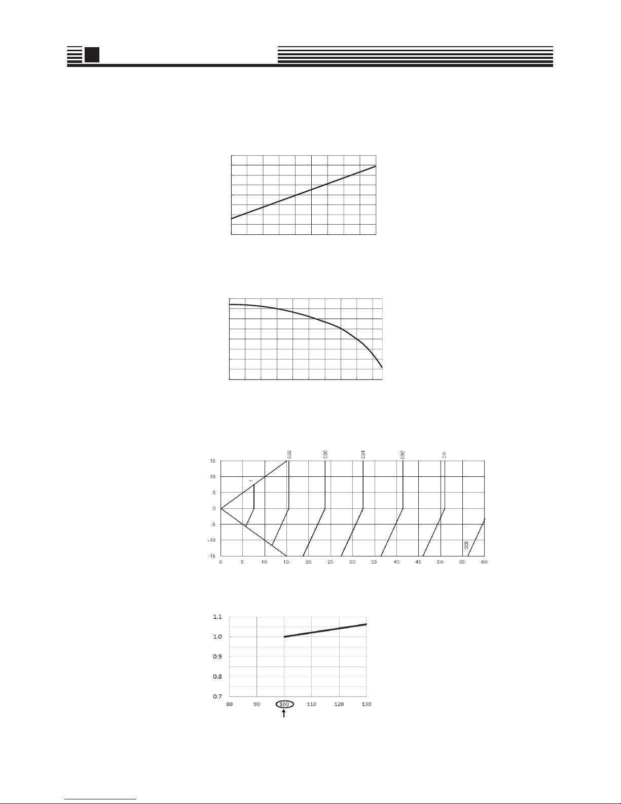
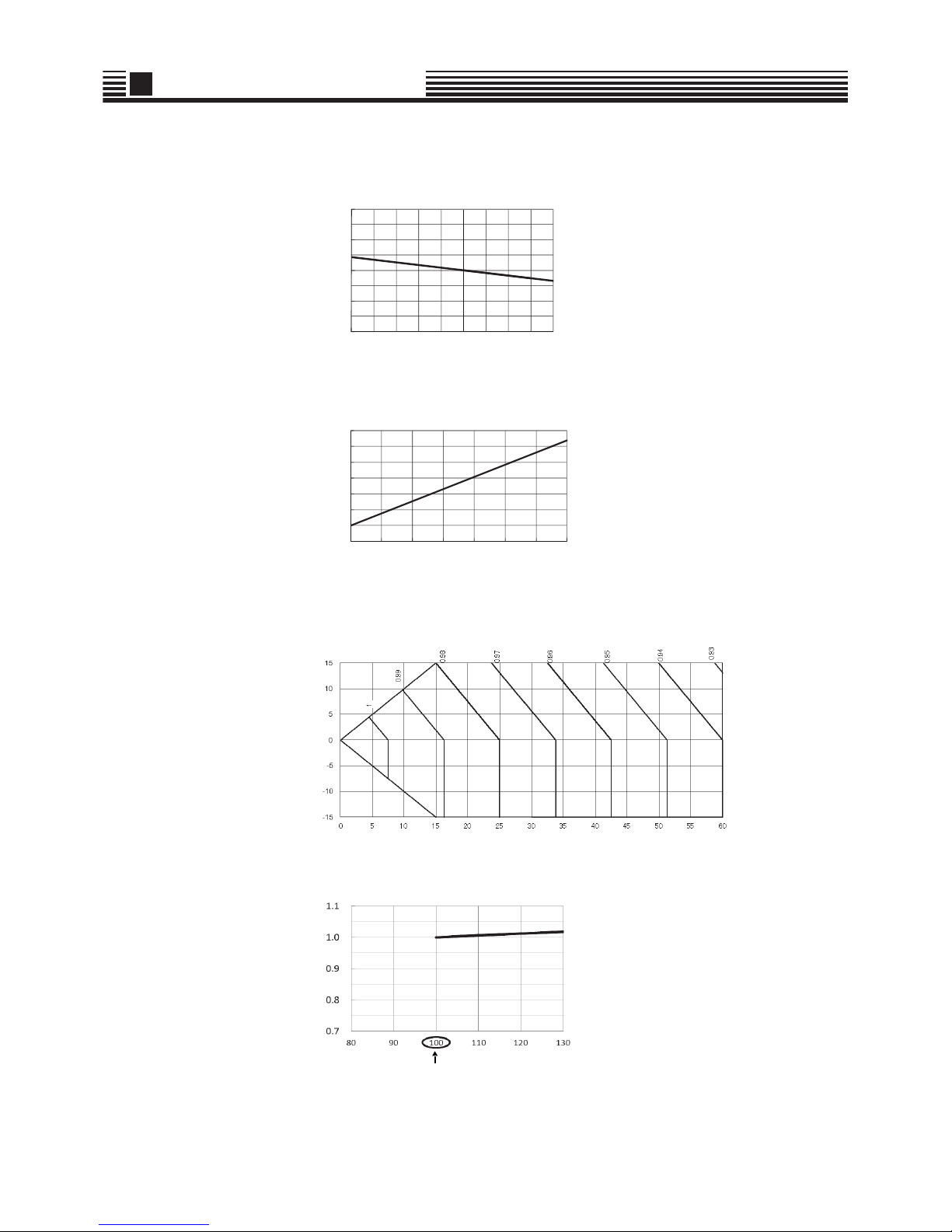
2-3-1. Correction charts for cooling capacity calculation
[1] Capacity correction value vs. indoor air wet bulb temperature
[2] Capacity correction value vs. outdoor air dry bulb temperature
[3] Capacity correction value vs. connecting pipe length and lift difference between indoor and
outdoor units
[4]* Correction of outdoor unit diversity
* : Coefficient to use for correction of outdoor unit capacity when total capacity of the indoor units are not equal to the outdoor unit
capacity.
㪇㪅㪏㩷
㪇㪅㪐㩷
㪈㪅㪇㩷
㪈㪅㪈㩷
㪈㪅㪉㩷
㪈㪌 㪉㪇
Capacity correction value
Indoor air wet bulb temp. (°C)
0.8
0.9
1.0
1.1
1.2
-5 0 5 10 15 20 25 30 35 40
Capacity correction value
Outdoor air dry bulb temp. (°C)
Height of outdoor unit H [m]
Pipe length (Equivalent length) L [m]
Capacity correction value
Indoor units total capacity ratio (%)
Standard capacity ratio
13
2
Equipment selection procedure
2-3-2. Correction charts for heating capacity calculation
[1] Capacity correction value vs. indoor air dry bulb temperature
[2] Capacity correction value vs. outdoor air wet bulb temperature
[3] Capacity correction value vs. connecting pipe length and lift difference between indoor and
outdoor units
[4]* Correction of outdoor unit diversity
* : Coefficient to use for correction of outdoor unit capacity when total capacity of the indoor units are not equal to the outdoor unit
capacity.
0.8
0.9
1.0
1.1
1.2
15 20
Capacity correction value
Indoor air dry bulb temp. (°C)
0.5
0.6
0.7
0.8
0.9
1.0
1.1
1.2
-20 -15 -10 -5 0 5 10 15
Capacity correction value
Outdoor air wet bulb temp. (°C)
Height of outdoor unit H [m]
Pipe length (Equivalent length) L [m]
Capacity correction value
Indoor units total capacity ratio (%)
Standard capacity ratio
14
2
Equipment selection procedure
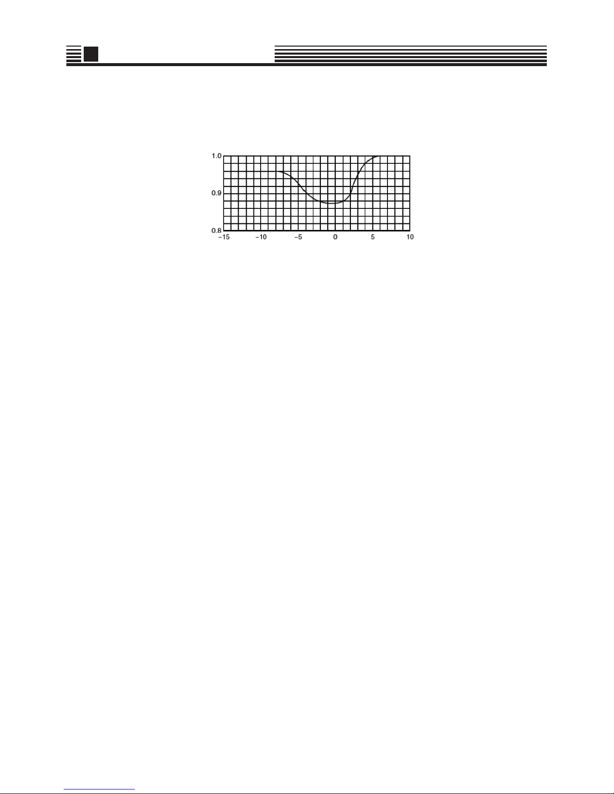
2-3-3. Capacity correction in case of frost on the outdoor heat exchanger in heating
Correct the heating capacity when frost was found on the outdoor heat exchanger.
Heating capacity = Capacity after correction of outdoor unit x Correction value of capacity resulted from frost
(Capacity after correction of outdoor unit: Heating capacity calculated in the above item 2.)
[5] capacity correction in case of frost on the outdoor heat exchanger
Capacity correction value
Outdoor air wet bulb temp. (°C)

15
2
Equipment selection procedure
2-4. Operational temperature range
The unit will operate down to an outdoor temperature of -20 °C, however considerable performance decrease will be expected below -15 °C.
Therefore please consider installation location/surroundings and system design when expected to operate between -15 °C and -20 °C.
Outdoor air dry bulb temp. (°C)
Indoor air wet bulb temp. (°C)
Cooling
Indoor air dry bulb temp. (°C)
Outdoor air wet bulb temp. (°C)
Heating

16
Side blow VRF Data book
3
Refrigerant piping design
3-1. Free branching system
[1] Line br an ch ing syste m
[2] Header branching system
[3] Header branching system after line branching
[4] Line branching system after header branching
[5] Header branching system after header branching
The above five branching systems enable to dramatically increase the flexibility of refrigerant piping design.
Line branching
system
Header
branching
system
Header
branching
system
Line branching
system after
header
branching
Header
branching
system after
header
branching
Branching joint
Indoor unit
Remote
controller
Outdoor
Branching header
Remote
controller
Outdoor
* In case of "PMV Kit"
Branching header
Branching joint
Remote
controller
PMV Kit
*
Indoor unit
Outdoor
* In case of "PMV Kit"
Branching header
Branching joint
Remote
controller
*
Indoor unit
Branching header
Outdoor

17
3 Refrigerant piping design
3-2. Allowable length / height difference of refrigerant piping
*1 Furthest indoor unit from 1st branch to be named "A"
Allowable value Piping section
Pipe Length
Total extension of pipe (Liquid pipe, real length) 90 m L1 + L2 + L3 + a + b + c + d + e + f
Furthest piping length L (*1)
Real length 50 m
L1 + L3 + f
Equivalent length 60 m
Max. real length of main pipe 30 m L1
Max. real length of furthest piping from 1st branching Li (*1) 20 m L3 + f
Max. real length of indoor unit connecting pipe 10 m a, b, c, d, e, f
Height
Difference
Height between indoor and outdoor units H1
Upper outdoor unit 15 m ―
Lower outdoor unit 15 m ―
Height between indoor units H2 10 m ―
f
abcd
A
*1
L3
L1
L2
e
Outdoor unit
Height difference
between indoor and
outdoor units H1
Main
pipe
1st branching
section
Branching pipe
Branching
header
Indoor unit
Y-shaped
branching joint
Branching pipe
Equivalent length corresponded to farthest piping L
Equivalent length corresponded to farthest piping after 1st b ranching Li
Height
difference
between indoor
units H2

18
3 Refrigerant piping design
3-3. Selection of refrigerant piping
No. Piping parts Name Selection of pipe size Remarks
(1)
Outdoor unit
1st branching
section
Main pipe
Size of main pipe
Same as connecting pipe
size of the outdoor unit.
(2)
Branching section
Branching section
Branching pipe
Pipe size between branching sections
Pipe size differs based on the
total capacity code value of
indoor units at the
downstream side. If the total
value exceeds the capacity
code of the outdoor unit,
apply the capacity code of the
outdoor unit.
(3)
Branching section
Indoor unit
Indoor unit
connecting pipe
Connecting pipe size of indoor unit
(4) Branching section
Y-shaped
branching joint
Selection of branching section (Y-shaped branching joint)
(5) Branching section
Branching
header
Selection of branching section (Branching header)
(5)
(2)
(4)
(1)
(3)
(3)
(3)
(3)
(2)
(4)
(3)
(3)
Outdoor unit
Liquid pipe
Gas pipe
Main pipe
1st branching
section
Branching
pipe
Branching
header
Indoor
unit
Indoor
unit
Branching
pipe
Y-shaped
branching joint
→
Outdoor unit capacity type Gas pipe Liquid pipe
0404 type 15.88 9.52
0504 type 15.88 9.52
0604 type 19.05 9.52
→
Total capacity codes of indoor units at down
stream side
Gas pipe Liquid pipe
Equivalent to HP Equivalent to capacity
Below 2.4 Below 6.6 12.70 9.52
2.4 to below 6.4 6.6 to below 18.0 15.88 9.52
6.4 or more 18.0 or more 19.05 9.52
→
Capacity rank Gas pipe Liquid pipe
005 to 012 type 9.52 6.35
014 to 018 type 12.70 6.35
020 to 056 type 15.88 9.52
Model name
Y-shape branch joint RBM-BY55E
Model name
Branching header
For 4 branches RBM-HY1043E
For 8 branches RBM-HY1083E

19
3 Refrigerant piping design
3-4. Allowable length / height difference of refrigerant piping with PMV
Kit
*1 Furthest indoor unit from 1st branch to be named "A"
Allowable value Piping section
Pipe Length
Total extension of pipe (Liquid pipe, real length) 75 m
L1 + L2 + L3 + a + b + c + d + e + f + g + h + i
+ j + k + l
Furthest piping length L (*1)
Real length 40 m
L1 + L3 + f + l
Equivalent length 50 m
Max. real length of main pipe 25 m L1
Max. real length of furthest piping from 1st branching Li (*1) 15 m L3 + f + l
Max. real length of indoor unit connecting pipe 10 m a + g, b + h, c + i, d + j, e + k, f + l
Real length between PMV Kit and indoor unit
2 m or more
Below 10 m
g, h, i, j, k, l
Height
Difference
Height between indoor and outdoor units H1
Upper outdoor unit 15 m ―
Lower outdoor unit 15 m ―
Height between indoor unit and PMV Kit H2 10 m ―
NOTE
Do not connect two or more indoor units to one PMV Kit.
Arrange one indoor unit and one PMV Kit set to 1 by 1.
KODOOG ON
PMV Kit
PMV Kit
tinu roodnItinu roodnI
e
l
f
ab
ghij
cd
H2
H2
H2
A
*1
L3
L1
L2
k
Outdoor unit
Height
difference
between
indoor and
outdoor
units H1
Main
pipe
1st branching
section
Branching pipe
Branching
header
Indoor unit
Y-shaped
branching joint
Branching pipe
Equivalent length corresponded to farthest piping L
Equivalent length corresponded to farthest piping after 1st branching Li
Height difference
between indoor unit
and PMV Kit H2 *
* Between highest
unit and lower
units.
PMV Kit
Example)

20
3 Refrigerant piping design
3-5. Selection of refrigerant piping with PMV Kit
No. Piping parts Name Selection of pipe size Remarks
(1)
Outdoor unit
1st branching
section
Main pipe
Size of main pipe
Same as connecting pipe
size of the outdoor unit.
(2)
Branching section
Branching section
Branching pipe
Pipe size between branching sections
Pipe size differs based on the
total capacity code value of
indoor units at the
downstream side. If the total
value exceeds the capacity
code of the outdoor unit,
apply the capacity code of the
outdoor unit.
(3)
Branching section
Indoor unit
Indoor unit
connecting pipe
Connecting pipe size of indoor unit
(4) Branching section
Y-shaped
branching joint
Selection of branching section (Y-shaped branching joint)
(5) Branching section
Branching
header
Selection of branching section (Branching header)
(6) PMV Kit PMV Kit
Selection of PMV Kit
* PMV kit can be connected less than 027 type FCU.
)5(
)2(
)4(
)1(
)3(
6()
)3(
()3
)2(
()4
)3(
()6
)6(
()6
)3(
6()
3()
)6(
Outdoor unit
Liquid pipe
Gas pipe
Main pipe
1st branching
section
Branching
pipe
Branching
header
Indoor
unit
Indoor
unit
Branching
pipe
Y-shaped
branching joint
PMV Kit
→
Outdoor unit capacity type Gas pipe Liquid pipe
0404 type 15.9 9.5
0504 type 15.9 9.5
0604 type 19.1 9.5
→
Total capacity codes of indoor units at down
stream side
Gas pipe Liquid pipe
Equivalent to HP Equivalent to capacity
Below 2.4 Below 6.6
12.7 9.5
2.4 to below 6.4 6.6 to below 18.0 15.9 9.5
6.4 or more 18.0 or more 19.1 9.5
→
Capacity rank Gas pipe Liquid pipe
005 to 012 type 9.5 6.4
014 to 018 type 12.7 6.4
024 to 056 type 15.9 9.5
Model name
Y-shape branch joint RBM-B Y55E
Model name
Branching header
For 4 branches RBM-HY1043E
For 8 branches RBM-HY1083E
Indoor unit capacity type Model name
005 to 014 type RBM-PMV0362E
015 to 027 type RBM-PMV0902E

21
3 Refrigerant piping design
3-6. Charging requirement with additional refrigerant
After finishing vacuuming, exchange the vacuum pump with a refrig erant canister and start additional charging of refrigerant.
Refrigerant amount charged in factory
Calculation of additional refrigerant charge amount
Refrigerant charge amount factory default does not include the refrigerant for pipes at the local site.
For refrigerant to be charged in pipes at the local site, calculate the amount and charge it additionally.
When the additional refrigerant amount indicates minus as the result of calculation, it is not necessary to subtract any refrigerant.
Calculating formula
Ta ble 1
Table2
*1: Capacity code of 005 type is the same as 007 type. (kg)
Ta ble 3
Outdoor unit type MHP0404 MHP0504 MHP0604
Charging amount (kg) 3.9 3.9 3.9
Liquid pipe diameter (mm) 6.4 9.5
Additional refrigerant amount /1 m liquid pipe (kg/m) 0.025 0.055
Capacity rank
005(*1) 007 009 012 015 018 024 027 030 036 048 056
Capacity code (Equivalent to HP)
0.8 0.8 1.0 1.25 1.7 2.0 2.5 3.0 3.2 4.0 5.0 6.0
Indoor unit
model name
4-way cassette
MMU-AP****H
- - 0.4 0.4 0.8 0.8 0.8 0.8 0.8 1.2 1.2 1.2
MMU-AP****MH*
0.40.40.40.40.60.6------
2-way cassette MMU-AP****WH*
- 0.4 0.4 0.4 0.5 0.7 0.7 0.7 0.7 1.1 1.1 1.1
1-way cassette MMU-AP****YH / SH*
-0.40.40.40.50.50.6-----
Duct
MMD-AP****BH*
- 0.3 0.3 0.3 0.5 0.5 0.8 0.8 0.8 1.1 1.1 1.1
MMD-AP****S(P)H*
0.30.30.30.30.50.50.80.8----
MMD-AP****H*
- ----0.81.01.0-1.01.3-
Under-ceiling
MMC-AP****HP*
- - - - 0.6 0.6 0.8 0.8 - 1.2 1.2 1.2
MMC-AP****H*
- - - - 0.5 0.5 0.7 0.7 - 1.1 1.1 -
High wall
MMK-AP****H*
-0.50.50.50.70.70.7-----
MMK-AP****MH*
-0.30.30.3--------
Floor standing
MMF-AP****H*
- - - - 0.7 0.7 1.0 1.0 - 1.3 1.3 1.3
MML-AP****H*
-0.50.50.50.50.80.8-----
MML-AP****BH*
-0.30.30.30.50.50.7-----
MML-AP****NH*
-0.50.50.50.50.5------
Outdoor unit capacity type MCY- MHP0404 MHP05 04 MHP0604
Compensation by outdoor HP (kg) -1.6 -1.6 -1.6
NOTE
Additional refrigerant
charge amount at
lacal site (kg)
Real length of
liquid pipe
Additional refrigerant
charge amount per 1 m
liquid pipe (Table 1)
Corrective amount of
refrigerant depending on
the indoor units (Table 2)
Compensation by
outdoor HP (Table 3)
=x + +

22
Side blow VRF Data book
4 Wiring design
4-1. General
• The appliance shall be installed in a accordance with national wiring regulations.
Capacity shortages of the power circuit or an incomplete installation may cause an electric shock or fire.
• Perform wiring of power supply complying with the rules and regulations of the local electric company.
• Never connect AC voltage power to the control wiring terminal block (U1,U2,U3,U4); otherwise the unit may break
down.
• Be sure that electric wiring does not come into contact with high-temperature parts of piping;
otherwise the coating of cables may melt and cause an accident.
• Locate wiring system for the control and refrigerant piping system in the same line.
• Do not turn on the power supply of the indoor units until vacuuming of the refrigerant pipe has finished.
• For the wiring of power to indoor units and that between indoor and outdoor units, follow the instructions in the
installation manual of each indoor unit.
4-2. Electrical wiring design
Determine the wire size for the indoor unit according to the number of connected indoor units downstream.
4-3. Outdoor unit power supply
Electrical characteristics
MCA : Maximum Circuit Amps
MOCP : Maximum Overcurrent Protection (Amps)
Model name
Normal Voltage
(V-Ph-Hz)
Voltage Range Compressor Fan Motor Power Supply
Min Max kW kW MCA MOCP
MCY-MHP0404HT-E 230 - 1 - 50 198 264 3.75 0.100 × 2 23.5 32.0
MCY-MHP0504HT-E 230 - 1 - 50 198 264 3.75 0.100 × 2 26.5 32.0
MCY-MHP0604HT-E 230 - 1 - 50 198 264 3.75 0.100 × 2 28.0 32.0
Pull box
Indoor unitIndoor unitIndoor unit
Indoor unitIndoor unitIndoor unit
Single phase
50 Hz 220-240V
Earth leakage breaker
power switch
Circuit breaker
(Earth leakage breaker)
Main switch
(Fuse)
Outdoor
power source
Indoor
power source

23
4 Wiring design
4-4. Indoor unit power supply
Electrical characteristics
Type Model
Nominal
Voltage
(V-Ph-Hz)
Voltage Range Fan Motor Power Supply
Min Max kW FLA MCA MOCP
4-Way Air
Discharge
Cassette Type
MMU-AP0092H
230-1-50 198 264 0.014 0.63 0.79 15
MMU-AP0122H
230-1-50 198 264 0.014 0.63 0.79 15
MMU-AP0152H
230-1-50 198 264 0.014 0.80 1.00 15
MMU-AP0182H
230-1-50 198 264 0.014 0.80 1.00 15
MMU-AP0242H
230-1-50 198 264 0.020 0.87 1.09 15
MMU-AP0272H
230-1-50 198 264 0.020 0.87 1.09 15
MMU-AP0302H
230-1-50 198 264 0.020 0.87 1.09 15
MMU-AP0362H
230-1-50 198 264 0.068 1.15 1.44 15
MMU-AP0482H
230-1-50 198 264 0.072 1.15 1.44 15
MMU-AP0562H
230-1-50 198 264 0.072 1.15 1.44 15
MMU-AP0094HP-E
230-1-50 198 264 0.014 0.63 0.79 15
MMU-AP0124HP-E
230-1-50 198 264 0.014 0.63 0.79 15
MMU-AP0154HP-E
230-1-50 198 264 0.014 0.80 1.00 15
MMU-AP0184HP-E
230-1-50 198 264 0.014 0.80 1.00 15
MMU-AP0244HP-E
230-1-50 198 264 0.020 0.87 1.09 15
MMU-AP0274HP-E
230-1-50 198 264 0.020 0.87 1.09 15
MMU-AP0304HP-E
230-1-50 198 264 0.020 0.87 1.09 15
MMU-AP0364HP-E
230-1-50 198 264 0.068 1.15 1.44 15
MMU-AP0484HP-E
230-1-50 198 264 0.072 1.15 1.44 15
MMU-AP0564HP-E
230-1-50 198 264 0.072 1.15 1.44 15
Compact 4-way
Cassette
(600 x 600) Type
MMU-AP0054MH-E
230-1-50 198 264 0.060 0.32 0.40 15
MMU-AP0074MH-E
230-1-50 198 264 0.060 0.32 0.40 15
MMU-AP0094MH-E
230-1-50 198 264 0.060 0.35 0.44 15
MMU-AP0124MH-E
230-1-50 198 264 0.060 0.36 0.45 15
MMU-AP0154MH-E
230-1-50 198 264 0.060 0.48 0.60 15
MMU-AP0184MH-E
230-1-50 198 264 0.060 0.48 0.60 15
2-Way Air
Discharge
Cassette Type
MMU-AP0072WH
230-1-50 198 264 0.020 0.32 0.40 15
MMU-AP0092WH
230-1-50 198 264 0.020 0.32 0.40 15
MMU-AP0122WH
230-1-50 198 264 0.020 0.32 0.40 15
MMU-AP0152WH
230-1-50 198 264 0.020 0.32 0.40 15
MMU-AP0182WH
230-1-50 198 264 0.030 0.70 0.88 15
MMU-AP0242WH
230-1-50 198 264 0.040 0.81 1.01 15
MMU-AP0272WH
230-1-50 198 264 0.040 0.81 1.01 15
MMU-AP0302WH
230-1-50 198 264 0.050 0.81 1.01 15
MMU-AP0362WH
230-1-50 198 264 0.070 0.87 1.09 15
MMU-AP0485WH
230-1-50 198 264 0.070 0.87 1.09 15
MMU-AP0562WH
230-1-50 198 264 0.070 0.87 1.09 15
1-Way Air
Discharge
Cassette Type
MMU-AP0074YH-E
230-1-50 198 264 0.022 0.28 0.35 15
MMU-AP0094YH-E
230-1-50 198 264 0.022 0.28 0.35 15
MMU-AP0124YH-E
230-1-50 198 264 0.022 0.28 0.35 15
MMU-AP0154SH-E
230-1-50 198 264 0.030 0.40 0.49 15
MMU-AP0184SH-E
230-1-50 198 264 0.030 0.42 0.53 15
MMU-AP0244SH-E
230-1-50 198 264 0.030 0.71 0.88 15

24
4 Wiring design
Concealed Duct Type
MMD-AP0076BHP-E
230-1-50 198 264 0.150 0.30 0.37 15
MMD-AP0096BHP-E
230-1-50 198 264 0.150 0.34 0.42 15
MMD-AP0126BHP-E
230-1-50 198 264 0.150 0.34 0.42 15
MMD-AP0156BHP-E
230-1-50 198 264 0.150 0.48 0.61 15
MMD-AP0186BHP-E
230-1-50 198 264 0.150 0.48 0.61 15
MMD-AP0246BHP-E
230-1-50 198 264 0.150 0.60 0.75 15
MMD-AP0276BHP-E
230-1-50 198 264 0.150 0.60 0.75 15
MMD-AP0306BHP-E
230-1-50 198 264 0.150 0.70 0.88 15
MMD-AP0366BHP-E
230-1-50 198 264 0.250 1.23 1.54 15
MMD-AP0486BHP-E
230-1-50 198 264 0.250 1.41 1.77 15
MMD-AP0566BHP-E
230-1-50 198 264 0.250 1.41 1.77 15
Concealed Duct
High Static
Pressure Type
MMD-AP0184H-E
230-1-50 198 264 0.160 0.93 1.16 15
MMD-AP0244H-E
230-1-50 198 264 0.160 1.55 1.94 15
MMD-AP0274H-E
230-1-50 198 264 0.160 1.55 1.94 15
MMD-AP0364H-E
230-1-50 198 264 0.260 1.87 2.34 15
MMD-AP0484H-E
230-1-50 198 264 0.260 2.12 2.65 15
Slim Duct Type
MMD-AP0054SPH-E
230-1-50 198 264 0.060 0.35 0.44 15
MMD-AP0074SPH-E
230-1-50 198 264 0.060 0.35 0.44 15
MMD-AP0094SPH-E
230-1-50 198 264 0.060 0.35 0.44 15
MMD-AP0124SPH-E
230-1-50 198 264 0.060 0.37 0.47 15
MMD-AP0154SPH-E
230-1-50 198 264 0.060 0.38 0.48 15
MMD-AP0184SPH-E
230-1-50 198 264 0.060 0.47 0.59 15
Ceiling Type
MMC-AP0154H-E
230-1-50 198 264 0.030 0.33 0.41 15
MMC-AP0184H-E
230-1-50 198 264 0.030 0.37 0.46 15
MMC-AP0244H-E
230-1-50 198 264 0.040 0.48 0.60 15
MMC-AP0274H-E
230-1-50 198 264 0.040 0.48 0.60 15
MMC-AP0364H-E
230-1-50 198 264 0.080 0.90 1.13 15
MMC-AP0484H-E
230-1-50 198 264 0.080 0.96 1.20 15
MMC-AP0157HP-E
230-1-50 198 264 0.139 1.14 1.43 15
MMC-AP0187HP-E
230-1-50 198 264 0.139 0.89 1.11 15
MMC-AP0247HP-E
230-1-50 198 264 0.139 0.89 1.11 15
MMC-AP0277HP-E
230-1-50 198 264 0.094 0.75 0.93 15
MMC-AP0367HP-E
230-1-50 198 264 0.094 0.75 0.93 15
MMC-AP0487HP-E
230-1-50 198 264 0.094 0.42 0.53 15
MMC-AP0567HP-E
230-1-50 198 264 0.094 0.41 0.52 15
High-wall Type
(3 series)
MMK-AP0073H
230-1-50 198 264 0.030 0.20 0.22 15
MMK-AP0093H
230-1-50 198 264 0.030 0.22 0.24 15
MMK-AP0123H
230-1-50 198 264 0.030 0.22 0.24 15
MMK-AP0153H
230-1-50 198 264 0.030 0.37 0.40 15
MMK-AP0183H
230-1-50 198 264 0.030 0.37 0.40 15
MMK-AP0243H
230-1-50 198 264 0.030 0.43 0.47 15
High-wall Type
(4 series)
MMK-AP0074MH-E
230-1-50 198 264 0.030 0.20 0.24 15
MMK-AP0094MH-E
230-1-50 198 264 0.030 0.21 0.26 15
MMK-AP0124MH-E
230-1-50 198 264 0.030 0.22 0.27 15
Type Model
Nominal
Voltage
(V-Ph-Hz)
V
o
ltage Range Fan Motor Power Supply
Min Max kW FLA MCA MOCP

25
4 Wiring design
• Wiring size
Must be independent from the outdoor unit power supply
NOTE:
The above connecting lengths stated in the table, indicate the length from the isolator to the outdoor unit. When the
power supply of the indoor units are connected in parallel, it is assumed that no more than a 2 % voltage drop will occur .
If the connecting length is to exceed the stated lengths, se lect a su it a ble wire in accordance with the local wiring
standards.
Floor Standing
Cabinet Type
MML-AP0074H-E
230-1-50 198 264 0.045 0.30 0.37 15
MML-AP0094H-E
230-1-50 198 264 0.045 0.30 0.37 15
MML-AP0124H-E
230-1-50 198 264 0.045 0.49 0.62 15
MML-AP0154H-E
230-1-50 198 264 0.045 0.49 0.62 15
MML-AP0184H-E
230-1-50 198 264 0.070 0.54 0.68 15
MML-AP0244H-E
230-1-50 198 264 0.070 0.54 0.68 15
Floor Standing
Concealed Type
MML-AP0074BH-E
230-1-50 198 264 0.019 0.29 0.36 15
MML-AP0094BH-E
230-1-50 198 264 0.019 0.29 0.36 15
MML-AP0124BH-E
230-1-50 198 264 0.019 0.29 0.36 15
MML-AP0154BH-E
230-1-50 198 264 0.070 0.52 0.65 15
MML-AP0184BH-E
230-1-50 198 264 0.070 0.52 0.65 15
MML-AP0244BH-E
230-1-50 198 264 0.070 0.53 0.66 15
Floor Standing Type
MMF-AP0154H-E
230-1-50 198 264 0.037 0.77 0.96 15
MMF-AP0184H-E
230-1-50 198 264 0.037 0.77 0.96 15
MMF-AP0244H-E
230-1-50 198 264 0.063 1.01 1.27 15
MMF-AP0274H-E
230-1-50 198 264 0.063 1.01 1.27 15
MMF-AP0364H-E
230-1-50 198 264 0.110 1.48 1.85 15
MMF-AP0484H-E
230-1-50 198 264 0.160 1.84 2.30 15
MMF-AP0564H-E
230-1-50 198 264 0.160 1.84 2.30 15
Console Type
MML-AP0074NH-E
230-1-50 198 264 0.041 0.21 0.26 15
MML-AP0094NH-E
230-1-50 198 264 0.041 0.21 0.26 15
MML-AP0124NH-E
230-1-50 198 264 0.041 0.25 0.31 15
MML-AP0154NH-E
230-1-50 198 264 0.041 0.32 0.40 15
MML-AP0184NH-E
230-1-50 198 264 0.041 0.46 0.58 15
Item
Model
Power supply wiring
Wire size
All models of indoor units
2.0 mm
2
(AWG#14) Max. 20 m 3.5 mm2 (AWG#12) Max. 50 m
Type Model
Nominal
Voltage
(V-Ph-Hz)
Voltage Range Fan Motor Power Supply
Min Max kW FLA MCA MOCP

26
4 Wiring design
4-5. Design of control wiring
4-5-1. Summary of control wiring
Control wiring and central control wiring use 2-core non-polarity wires.
Use 2-core shield wires to prevent noise trouble.
In this case, for the system grounding, close (connect) the end of shield wires, and isolate the end of terminal.
Use 2-core non-polarity wire for remote controller. (A, B terminals)
Use 2-core non-polarity wire for wiring of group control. (A, B terminals)
U1 U2U3 U4
U1 U2
U3 U4
U1 U2 A B 2UBAU1U2U1 A 2UBU1AB
BABABA
Central controller
Outdoor unit
Control wiring between indoor and outdoor unit
(Shield wire)
Control wiring between indoor units (Shield wire)
Indoor unit
Indoor unit
Indoor unit
Indoor unit
Remote controller
Remote controller
Remote controller
(Group control)
Open

27
4 Wiring design
4-5-2. Restriction of control wiring
Keep the rule of below tables about size and length of Control wiring.
Table-1 Control wiring between indoor and outdoor units (L1, L2, L3), Central control wiring (L4)
(*1): Total of control wiring length for all refrigerant circuits (L1 + L2 + L3 + L4)
Table-2 Control wiring between outdoor units (L5) (Other system)
Table-3 Remote controller wiring (L6, L7)
4-5-3. Group control through a remote controller
Group control of multiple indoor units (8 units) through a single remote controller
Wiring 2-core, non-polarity
Type Shield wire
Size/Length
*1
1.25 mm2: Up to 1000 m
2.0 mm
2
: Up to 2000 m
Wiring 2-core, non-polarity
Type Shield wire
Size/Length
1.25 mm
2
to 2.0 mm
2
Up to 100 m (L5)
Wire 2-core
Size
0.5 mm
2
to 2.0 mm
2
Length
Up to 500 m (L6 + L7)
Up to 400 m with of wireless remote controller in group control.
Up to 200 m total length of control wiring between indoor units (L6)
U3 U4
U1 U2
U1U3U2
U4
U1 U2
A B
U3 U4
U1 U2
U1 U2
A B
U1 U2
A B
U1
U2
A B
U1 U2
A B
U1
U2
A
B
U3 U4
U1 U2 U5 U6
U1 U2
A B
U1 U2
A B
U1 U2
A B
U3 U4
U1
U2
U5
U6
L1
L5
L6
L6
L7
L7
L4
3L2L
Header
unit
Follower
unit
Other system
Central
controller
Outdoor
unit
Indoor
unit
Table-1
Table-2
Table-1
Remote controller
Remote controllerRemote controller
U1 U2
A B
Table-3
This system
BABABABABABA
(A.B)
Remote controller
Indoor unit No.1
No.2
No.3
No.4
No.7
No.8

28
Side blow VRF Data book
5
Outdoor unit
5-1. Specifications
(*1) Rated conditions Cooling : Indoor 27 degC Dry Bulb / 19 degC Wet Bulb, Outdoor 35 degC Dry Bulb.
Heating : Indoor 20 degC Dry Bulb, Outdoor 7 degC Dry Bulb / 6 degC Wet Bulb.
The standard pipe means that equivalent piping length of 7.5 m and standard 0 m piping heigh t difference.
(*2) The source voltage must not fluctuate more than ±10%.
(*3) The amount dose not consider extra piping length and indoor unit type.
Refrigerant must be added on site in accordance with the actual piping length and indoor unit type.
(*4) Discharge temp. sensor / Suction temp. sensor / High-pressure sensor / Low-pressure sensor / Compressor case thermostat / PC board fuse
(*5) Select wire size base on the large value of MCA.
MCA : Minimum Circuit Amps
(*6) MOCP Maximum Overcurrent Protection (Amps)
Outdoor unit model name MCY-MHP0404HT-E MCY-MHP0504HT-E MCY-MHP0604HT-E
Outdoor unit type Inverter Inverter Inverter
Capacity code HP 4 5 6
Cooling Capacity
(*1)
kW 12.1 14.0 15.5
Heating Capacity
(*1)
kW 12.5 16.0 18.0
Electrical
characteristics
(Nominal) (*1)
Power supply (*2) 1phase 50Hz 220 / 230 / 240V 1phase 50Hz 220 / 230 / 240V 1phase 50Hz 220 / 230 / 240V
Cooling
Running current A 13.9 / 13.3 / 12.8 16.7 / 16.0 / 15.4 20.6 / 19.7 / 18.9
Power consumption kW 2.88 3.50 4.35
Power factor % 94 95 96
EER 4.20 4.00 3.56
Heating
Running current A 13.3 / 12.8 / 12.2 18.0 / 17.3 / 16.5 21.3 / 20.4 / 19.5
Power consumption kW 2.73 3.81 4.50
Power factor % 93 96 96
COP 4.58 4.20 4.00
Starting Current A Soft start Soft start Soft start
Dimension
Unit
Height mm 1,235 1,235 1,235
Width mm 990 990 990
Depth mm 390 390 390
Packing
Height mm 1,350 1,350 1,350
Width mm 1,102 1,102 1,102
Depth mm 552 552 552
Total Weight
Unit kg 116 116 116
Packed unit kg 124 124 124
Appearance (Color)
Silky shade
(Munsell 1Y8.5/0.5)
Silky shade
(Munsell 1Y8.5/0.5)
Silky shade
(Munsell 1Y8.5/0.5)
Compressor
Type Hermetic twin rotary compressor Hermetic twin rotary compressor Hermetic twin rotary compressor
Motor output kW 3.75 3.75 3.75
Fan unit
Fan Propeller fan (Quantity 2) Propeller fan (Quantity 2) Propeller fan (Quantity 2)
Motor output W 100 + 100 100 + 100 100 + 100
Air volume
m
3
/h
6,030 6,210 6,410
Heat exchanger Finned tube Finned tube Finned tube
Refrigerant R410A (Charged refrigerant amount (kg)) (*3) 3.9 3.9 3.9
Protective devices (*4)
Electrical
specifications
Unit
MCA (*5) A 23.5 26.5 28.0
MOCP (*6) A 32.0 32.0 32.0
Refrigerant
piping
Connecting port
diameter
Gas side (main pipe) mm 15.9 15.9 19.1
Liquid side (main pipe) mm 9.5 9.5 9.5
Connecting
method
Gas side Flare Flare Flare
Liquid side Flare Flare Flare
Max. No. of connected indoor units 6 6 6
Sound pressure level
Cooling dB(A) 50 51 52
Heating dB(A) 52 54 55
Operation temperature range
Cooling CDB -5 to 43 -5 to 43 -5 to 43
Heating CWB -20 to 15 -20 to 15 -20 to 15

29
5 Outdoor unit
5-2. Dimensional drawing
MCY-MHP0404HT-E, MCY-MHP0504HT-E, MCY-MHP0604HT-E

30
5 Outdoor unit
5-3. Branch header / branch joint
• Branch header
RBM-HY1043E, HY1083E
• Y-shape branch joint
RBM-BY55E
• Accessory socket
Model A B C øD øE n Accessory socket Qty
RBM-HY1043E
Gas side 380 90 8 3 .6 22.2 15.9 3
x 4, x 4, x 1, x 1, x 1
Liquid side 360 60 - 15.9 9.5 3
x 4, x 1, x 1
RBM-HY1083E
Gas side 700 90 8 3 .6 22.2 15.9 7
x 8, x 8, x 1, x 1, x 1
Liquid side 680 60 - 15.9 9.5 7
x 8, x 1, x 1
Model A B øC øD Accessory socket Qty
RBM-BY55E
Gas side 160 80 1 5 .9 15.9
x 1, x 2, x 2
Liquid side 130 70 9.5 9.5
x 2
Gas side
Liquid side
Gas side Liquid side
Outer dia.
Outer dia.
Outer dia.Outer dia.
369O1 dh{}+-
A B C D
58 9.5 12.7 15.9
71
15.9 19.1 22.2
80
22.2 25.4 28.6
87
25.4 28.6 31.8
95
28.6 31.8 38.1
A B
40d 15.9
40
h 19.1
48
{ 25.4
54
} 28.6
41
+ 12.7
44
- 9.5
A B
353 6.4
32
6 9.5
28
9 12.7
37.5
O 19.1

31
5 Outdoor unit
5-4. Refrigerant cycle diagram
Sensor (TO)
Heat exc han ger
Sensor (TE)
Compressor
thermo.
Solenoid
valve
(SV5)
Strainer
PMV
Strainer
Sensor (TL)
Liquid side
packed valve
Gas side
ball valve
Compressor
Strainer
Sensor (TD)
4-Way valve
Sensor (TS)
Solenoid
valve
Solenoid
valve
Capillary
tube
Check joint
Muffler
High pressure
sensor
Check joint
Low pressure
sensor
Accumulator
High pressure
SW

32
5 Outdoor unit
5-5. Wiring diagram
MCY-MHP0404HT-E, MCY-MHP0504HT-E, MCY-MHP0604HT-E

33
5 Outdoor unit
5-6. Connecting diagram
MCY-MHP0404HT-E, MCY-MHP0504HT-E, MCY-MHP0604HT-E
Central remote controller power supply
1N~ 50Hz 220-240V
䐢䐢
LN
U1
U2
U3 U4
䐟
U1
U2 U3U4
Earth
䐠 䐠 䐠 䐠
U1 U2
A
2U1UB
A
2U1UB
A
2U1UB
A
B
Indoor control
䐧 PC boad NLNLNL
LN
䐡 䐡 䐡
ABABA
B
Indoor unit
power supply
1N~ 50Hz
220-240V
䐦 䐦 䐦
Earth
htraEhtraEhtraE
Earth
CN02
CN01
䐣
䐤
䐣䐤
㻯㻺㻤㻞
(Open)
*1
*3
*2
W2
W1
䐣
䐤
LN
Outdoor power supply
1N~ 50Hz 220-240V
(Note)
1. When perform a central control, connect the wire of CN01 in CN02. (Factory
default : No connection)
2. Connection of shield wire must be connected. (Connected to all connecting
sections in each Indoor unit)
3. Group control
4. Select the power supply wiring and fuse of outdoor/indoor units according to e ach
models specification. Perform wiring of power supply complying with the rules
and regulations of the local electric company.
5. Fro the control wires connecting indoor units, outdoor units, and between indoor
and outdoor units, use 2-core and non-polarity shield wires.
6. As for details, see the wiring diagram of indoor/outdoor unit.
(1) Outdoor unit
(2) Indoor unit
(3) Remote controller
(4) Central remote controller (option)
(5) Main switch (Fuse)
(6) Circuit breaker (Earth leakage breaker)
(7) Pull box
(8) PMV Kit (option)
W1 Control wiring between indoor and outdoor units.
W2 Control wiring between indoor units.

34
5 Outdoor unit
5-7. Optional printed circuit board (PCB) of outdoor unit
Model
name
Appearance Function
TCB-PCDM4E
Size : 71 x 85 (mm)
Power peak-cut Control
Standard Specifications
(Wiring example)
Enhanced Specifications
(Wiring example)
Application
* Installation the optional PCB
in the interface board of the
outdoor unit.
PJ17
CN513
SW07
TB1
[ON]
[OFF]
TB2
COM
ON
COM
OFF
Bit 2 OFF
L1
SW1
SW2
SW2
SW1
ON
OFF
1234
Outdoor unit
interface PCB
Connection cable (attached in this optional PCB)
Locally procured
Power
supply
[OPERATION]
L1: Display lamp during power peak cut control
For SW1 and SW2, be sure to provide no-voltage
contacts for each terminal.
The input signals of SW1 and SW2 may be pulse
input (100 msec or more) or continuous make.
Do not turn on [SW1] and [SW2] simultaneously.
Optional PCB
Display
relay
Shield
wire
Shield
wire
<SW07 (bit 2) OFF [2-stage switching]>
Input SW07 (bit 1)
Display relay (L1)
SW1 SW2 Bit 1 OFF Bit 1 ON
OFF ON
100 %
(normal operation)
100 %
(normal operation)
OFF
ON OFF 0 % (forced stop)
Approx. 60 %
(upper limit regulated)
ON
PJ17
TB1
[ON]
[OFF]
TB2
COM
ON
COM
OFF
CN513
SW07
Bit 2 ON
L1
SW1
ON
OFF
1234
SW2
Outdoor unit
interface PCB
Connection cable (attached in this optional PCB)
Locally procured
Power
supply
[OPERATION]
L1: Display lamp during power peak cut control
Optional PCB
Display
relay
For SW1 and SW2, be sure to
provide no-voltage contacts for
each terminal.
Shield
wire
Shield
wire
<SW07 (bit 2) ON [4-stage switching]>
Input SW07 (bit 1)
Display relay (L1)
SW1 SW2 Bit 1 OFF Bit 1 ON
OFF OFF
100 %
(normal operation)
100 %
(normal operation)
OFF
ON OFF
Approx. 80 %
(upper limit regulated)
Approx. 85 %
(upper limit regulated)
ON
OFF ON
Approx. 60 %
(upper limit regulated)
Approx. 75 %
(upper limit regulated)
ON
ON ON 0 % (forced stop)
Approx. 60 %
(upper limit regulated)
ON

35
5 Outdoor unit
TCB-PCMO4E
Size : 55.5 x 60 (mm)
[1] External master ON/OFF control
▼ Function
By connecting the cable (attached in this optional PCB) to the interface PC
board on an outdoor unit, all indoor units connecte d to the outdoor unit enable
to operate simultaneously.
SW1: Operation input switch
SW2: Stop input switch
Provide no-voltage pulse contacts for each terminal.
Hold the ON state for at least 100 msec.
Do not turn SW1 and SW2 ON simultaneously.
Application
* Installation the optional PCB
in the interface board of the
outdoor unit.
[2] Night time operation (sound reduction) control
▼ Function
As the cable (attached in this optional PCB) is connected to the “Interf ace
PCB” on an outdoor unit, both compressor speed and fan speed are restricted
while the signal of the night operation control is input. It makes the noise
reduction during the night time operation.
SW1: Night time signal switch
Each terminal should be connected to dry contact.
The input signal is recognized during its rising/falling phase.
(After reaching the top/bottom of the rising/falling edge, the signal must remain there for
at least 100 ms.)
Model
name
Appearance Function
71JP
CN512
TB1
SW1
SW2
COM
HEAT
COOL
Locally procured
Optional PCB
Shield
wire
Outdoor unit
interface PCB
Connection cable
(attached in this
optional PCB)
Terminal Input signal Operation
COOL (SW1)
ON
OFF
All indoor units operate together
HEAT (SW2)
ON
OFF
All indoor units stop together
71JP
TB1
SW1
COM
HEAT
COOL
Outdoor unit
interface PCB
Connection cable
(attached in this
optional PCB)
Locally procured
Optional PCB
Shield
wire
CN508
Terminal Input signal Operation
COOL (SW1)
ON
OFF
Night time control
ON
OFF
Normal operation

36
5 Outdoor unit
TCB-PCMO4E
Size : 55.5 x 60 (mm)
▼ Sound reduction and approximation capacity (reference)
* Position of noise measuring device: 1 m from the front face of the set and 1.5 m
above ground (anechoic sound)
[3] Operation mode selection control
▼ Function
The heating/cooling mode of the system can be selected by connecting to the
interface PCB of outdoor units.
SW1: Cooling mode specified input switch
SW2: Heating mode specified input switch
Each terminal should be connected to dry contact.
Indoor unit operation intervention function
The statuses of indoor units operating in a mode different from the selected
operation mode can be changed by changing the sta tus of a jumper wir e (J01)
provided on the interface P.C. board of outdoor unit.
Application
* Installation the optional PCB
in the interface board of the
outdoor unit.
Model
name
Appearance Function
Outdoor unit
(base unit)
During low-noise mode
dB(A)
Capacity
Cooling Heating Cooling Heating
Relative to
maximum
capacity
Model 0404* 47 50 approx. 85 % approx. 95 %
Model 0504* 47 50 approx. 80 % approx. 80 %
Model 0604* 50 50 approx. 80 % approx. 70 %
71JP
TB1
SW1
SW2
COM
HEAT
COOL
Outdoor unit
interface PCB
Connection cable
(attached in this
optional PCB)
Locally procured
Optional PCB
Shield
wire
CN510
Input Signal
Operation: Selected operation mode
Cooling (SW1) Heating (SW2)
ON OFF Cooling operation only
OFF ON Heating operation only
OFF OFF Normal operation
Jumper wire Descrip tion of intervention
J01 connected
(factory default)
All indoor units operating in a mode different from the selected
operation mode (prohibited-mode indoor units) become non-priority
units (thermostat OFF).
The display “ (operation ready)” appears on the remote controller
of prohibited-mode indoor units.
J01 cut The selected operation mode is imposed on all indoor units operating
in a different mode.
Mode selected at
P.C. board
Remote controller operation / display
Normal
All modes (COOL,
DRY , HEA T and FAN)
available
COOL
Only COOL, DRY
and FAN available
“ operation mode
control” (turned on
during remote
controller operation)
HEAT
Only HEAT and FAN
available

37
5 Outdoor unit
[PCB Installation Position]
TCB-PCIN4E
Size : 73 x 79 (mm)
Error / Operation Output
▼ Function
The operation error output PCB can indicate operation and error states by
connecting to the interface PCB of outdoor units.
▼ Operation
Operation output:The operation indicator is on while any indoor unit in the
system is operating.
Error output: The error indicator is on when an error is occurred on even
one of the indoor or outdoor units in the system.
Wiring example
* [OUTPUT3] is displayed when power is turned on.
Application
* Installation the optional PCB
in the interface board of the
outdoor unit.
Model
name
Appearance Function
OUTPUT1
PJ20
OUTPUT2
OUTPUT3
TB1
L1
L2
1
2
5
6
4
3
C1
PS
PS
K1
K2
1
ON
OFF
234
SW16
Outdoor unit
interface PCB
Optional PCB
Locally procured
Shield
wire
CN511
C1 Attached connection cable 1 (4wires)
CN511 Connector on interface side (green)
K1, K2 Relays
L1 Error indication Lamp
L2 Operation indication Lamp
OUTPUT1 Error output
OUTPUT2 Operation output
PJ20 Connector on optional PCB side
PS Power supply unit
TB1 Terminal block
There are holes on the metal of interface PCB, and the optional
PCBs are installed.
Two kinds of the optional PCBs are able to install on it.
TCB-PCIN4E
TCB-PCDM4E
TCB-PCMO4E
In case of
TCB-PCMO4E
TCB-PCDM4E
In case of
TCB-PCIN4E
TCB-PCMO4E
In case of
TCB-PCDM4E
TCB-PCIN4E
Installation position of optional PCB
Interface PCB

38
5 Outdoor unit
Dimensions of PCB
TCB-PCDM4E
TCB-PCMO4E
TCB-PCIN4E
Terminal
Screw M3 6
71
61
Terminal
Screw M4 8
4-4ø hole
85
75
OFF
OFF ON
MS
10
MS
OFF
COM COMON
ON
T82
T81
K100
PJ17
5
5
ICI
41
8
OPERATION
/
TOSHIBA
NCC-1212
Terminal
Screw M3 6
55.5
45.5
60
50
PJ17
TOSHIBA
NCC-1214
4-4ø hole
5
41
ICI
41
D2
HEAT
COM
COMCOOL
10
TB1
8
C4
C2
C3
K1
12
OUTPUT1 OUTPUT2 OUTPUT3
34 56
K2
1
PJ20
5
K3
TB1
MCC-1613-02
3D2D1D
63
73
69
79
4- 4 mm dia. mounting ho les
Te rminal block (M3)

39
5 Outdoor unit
5-8. Part load performance
MCY-MHP0404HT* (4HP, 12.1 kW system)
TC : Total Capacity PI : Power Input
Indoor air temperature conditions : 27.0 °C dry-bulb / 19.0 °C wet bulb
TC : Total Capacity PI : Power Input
Indoor air temperature conditions : 20.0 °C dry-bulb
All indoor unit operation
Cooling Compressor + Outdoor Fan Power consumption (kW)
Outdoor Unit
Dry-Bulb
(°C)
Outdoor Unit
100 % Cooling
Capacity (kW)
100 % 90 % 80 % 70 % 60 % 50 %
TC
(kW)
PI
(kW)TC(kW)PI(kW)TC(kW)PI(kW)TC(kW)PI(kW)TC(kW)PI(kW)TC(kW)PI(kW)
40 11.4 11.4
3.46 10.3 2.87 9.1 2.34 8.0 1.88 6.9 1.48 5.7 1.15
39 11.6 11.6
3.34 10.4 2.77 9.2 2.26 8.1 1.82 6.9 1.43 5.8 1.12
37 11.8 11.8
3.10 10.7 2.58 9.5 2.11 8.3 1.70 7.1 1.34 5.9 1.05
35 12.1 12.1
2.88 10.9 2.40 9.7 1.97 8.5 1.59 7.3 1.26 6.1 0.98
33 12.1 12.1
2.68 10.9 2.24 9.7 1.84 8.5 1.49 7.3 1.18 6.1 0.92
31 12.1 12.1
2.49 10.9 2.08 9.7 1.72 8.5 1.39 7.3 1.11 6.1 0.87
30 12.1 12.1
2.40 10.9 2.01 9.7 1.66 8.5 1.35 7.3 1.07 6.1 0.84
29 12.1 12.1
2.31 10.9 1.94 9.7 1.60 8.5 1.30 7.3 1.04 6.1 0.81
27 12.1 12.1
2.15 10.9 1.81 9.7 1.50 8.5 1.22 7.3 0.97 6.1 0.76
25 12.1 12.1
1.99 10.9 1.68 9.7 1.40 8.5 1.14 7.3 0.91 6.1 0.72
23 12.1 12.1
1.85 10.9 1.57 9.7 1.30 8.5 1.07 7.3 0.86 6.1 0.67
21 12.1 12.1
1.72 10.9 1.46 9.7 1.22 8.5 1.00 7.3 0.80 6.1 0.63
20 12.1 12.1
1.66 10.9 1.41 9.7 1.18 8.5 0.97 7.3 0.78 6.1 0.61
19 12.1 12.1
1.60 10.9 1.36 9.7 1.14 8.5 0.93 7.3 0.75 6.1 0.59
17 12.1 12.1
1.48 10.9 1.26 9.7 1.06 8.5 0.87 7.3 0.71 6.1 0.56
15 12.1 12.1
1.38 10.9 1.18 9.7 0.99 8.5 0.82 7.3 0.66 6.1 0.52
Heating Compressor + Outdoor Fan Power consumption (kW)
Outdoor Unit
Outdoor Unit
100 % Heating
Capacity (kW)
100 % 90 % 80 % 70 % 60 % 50 %
Dry-Bulb
(
°
C)
Wet-Bulb
(°C)
TC
(kW)PI(kW)TC(kW)PI(kW)TC(kW)PI(kW)TC(kW)PI(kW)TC(kW)PI(kW)TC(kW)PI(kW)
15.0 13.7 12.5 12.5
2.39 11.3 2.09 10.0 1.79 8.8 1.45 7.5 1.24 6.3 0.79
13.0 11.8 12.5 12.5
2.47 11.3 2.16 10.0 1.85 8.8 1.50 7.5 1.27 6.3 1.00
11.0 9.8 12.5 12.5
2.56 11.3 2.23 10.0 1.91 8.8 1.56 7.5 1.31 6.3 1.03
9.0 7.9 12.5 12.5
2.64 11.3 2.30 10.0 1.97 8.8 1.61 7.5 1.35 6.3 1.06
7.0 6.0 12.5 12.5
2.73 11.3 2.37 10.0 2.03 8.8 1.70 7.5 1.38 6.3 1.09
5.0 4.1 12.1 12.1
2.69 10.9 2.34 9.7 2.00 8.5 1.67 7.3 1.36 6.1 1.07
3.0 2.2 11.8 11.8
2.64 10.6 2.30 9.4 1.97 8.2 1.64 7.1 1.34 5.9 1.05
0.0 -0.7 11.2 11.2
2.58 10.1 2.24 9.0 1.92 7.8 1.60 6.7 1.31 5.6 1.03
-3.0 -3.7 10.6 10.6
2.52 9.6 2.19 8.5 1.87 7.4 1.56 6.4 1.28 5.3 1.00
-5.0 -5.6 10.3 10.3
2.47 9.2 2.15 8.2 1.84 7.2 1.54 6.2 1.26 5.1 0.98
-7.0 -7.6 9.9 9.9
2.43 8.9 2.12 7.9 1.81 6.9 1.51 5.0 1.24 4.9 0.97
-10.0 -10.5 9.3 9.3
2.37 8.4 2.06 7.5 1.76 6.5 1.47 5.6 1.21 4.7 0.94
-14.5 -15.0 8.5 8.5
2.27 7.6 1.98 6.8 1.69 5.9 1.41 5.1 1.16 4.2 0.90

40
5 Outdoor unit
MCY-MHP0504HT* (5HP, 14.0 kW system)
TC : Total Capacity PI : Power Input
Indoor air temperature conditions : 27.0 °C dry-bulb / 19.0 °C wet bulb
TC : Total Capacity PI : Power Input
Indoor air temperature conditions : 20.0 °C dry-bulb
All indoor unit operation
Cooling Compressor + Outdoor Fan Power consumption (kW)
Outdoor Unit
Dry-Bulb
(°C)
Outdoor Unit
100 % Cooling
Capacity (kW)
100 % 90 % 80 % 70 % 60 % 50 %
TC
(kW)
PI
(kW)TC(kW)PI(kW)TC(kW)PI(kW)TC(kW)PI(kW)TC(kW)PI(kW)TC(kW)PI(kW)
40 13.2 13.2
4.24 11.8 3.50 10.5 2.83 9.2 2.24 7.9 1.74 6.6 1.31
39 13.3 13.3
4.08 12.0 3.37 10.7 2.73 9.3 2.17 8.0 1.68 6.7 1.27
37 13.7 13.7
3.78 12.3 3.13 10.9 2.54 9.6 2.02 8.2 1.57 6.8 1.19
35 14.0 14.0
3.50 12.6 2.91 11.2 2.36 9.8 1.89 8.4 1.47 7.0 1.12
33 14.0 14.0
3.24 12.6 2.70 11.2 2.20 9.8 1.76 8.4 1.38 7.0 1.05
31 14.0 14.0
3.00 12.6 2.50 11.2 2.05 9.8 1.64 8.4 1.29 7.0 0.99
30 14.0 14.0
2.89 12.6 2.41 11.2 1.97 9.8 1.59 8.4 1.25 7.0 0.95
29 14.0 14.0
2.78 12.6 2.32 11.2 1.90 9.8 1.53 8.4 1.21 7.0 0.92
27 14.0 14.0
2.57 12.6 2.16 11.2 1.77 9.8 1.43 8.4 1.13 7.0 0.87
25 14.0 14.0
2.38 12.6 2.00 11.2 1.65 9.8 1.33 8.4 1.06 7.0 0.81
23 14.0 14.0
2.21 12.6 1.86 11.2 1.53 9.8 1.24 8.4 0.99 7.0 0.76
21 14.0 14.0
2.04 12.6 1.72 11.2 1.43 9.8 1.16 8.4 0.92 7.0 0.72
20 14.0 14.0
1.97 12.6 1.66 11.2 1.38 9.8 1.12 8.4 0.89 7.0 0.69
19 14.0 14.0
1.89 12.6 1.60 11.2 1.33 9.8 1.08 8.4 0.86 7.0 0.67
17 14.0 14.0
1.75 12.6 1.48 11.2 1.24 9.8 1.01 8.4 0.81 7.0 0.63
15 14.0 14.0
1.62 12.6 1.38 11.2 1.15 9.8 0.94 8.4 0.76 7.0 0.59
Heating Compressor + Outdoor Fan Power consumption (kW)
Outdoor Unit
Outdoor Unit
100 % Heating
Capacity (kW)
100 % 90 % 80 % 70 % 60 % 50 %
Dry-Bulb
(
°
C)
Wet-Bulb
(°C)
TC
(kW)PI(kW)TC(kW)PI(kW)TC(kW)PI(kW)TC(kW)PI(kW)TC(kW)PI(kW)TC(kW)PI(kW)
15.0 13.7 16.0 16.0
3.29 14.4 2.86 12.8 2.41 11.2 1.99 9.6 1.60 8.0 1.23
13.0 11.8 16.0 16.0
3.42 14.4 2.96 12.8 2.49 11.2 2.05 9.6 1.65 8.0 1.26
11.0 9.8 16.0 16.0
3.55 14.4 3.06 12.8 2.57 11.2 2.12 9.6 1.69 8.0 1.29
9.0 7.9 16.0 16.0
3.68 14.4 3.16 12.8 2.66 11.2 2.18 9.6 1.74 8.0 1.33
7.0 6.0 16.0 16.0
3.81 14.4 3.26 12.8 2.74 11.2 2.24 9.6 1.78 8.0 1.36
5.0 4.1 15.5 15.5
3.75 13.9 3.21 12.4 2.70 10.8 2.21 9.3 1.74 7.7 1.34
3.0 2.2 15.0 15.0
3.69 13.5 3.16 12.0 2.66 10.5 2.18 9.0 1.72 7.5 1.32
0.0 -0.7 14.2 14.2
3.60 12.8 3.09 11.4 2.59 9.9 2.13 8.5 1.69 7.1 1.29
-3.0 -3.7 13.4 13.4
3.52 12.1 3.01 10.7 2.53 9.4 2.08 8.0 1.66 6.7 1.26
-5.0 -5.6 12.9 12.9
3.46 11.6 2.96 10.3 2.49 9.0 2.04 7.7 1.64 6.4 1.24
-7.0 -7.6 12.4 12.4
3.40 11.1 2.91 9.9 2.44 8.7 2.01 7.4 1.62 6.2 1.22
-10.0 -10.5 11.6 11.6
3.31 10.4 2.83 9.3 2.38 8.1 1.95 7.0 1.59 5.8 1.19
-14.5 -15.0 10.4 10.4
3.17 9.4 2.72 8.3 2.29 7.3 1.88 6.3 1.55 5.2 1.14

41
5 Outdoor unit
MCY-MHP0604HT* (6HP, 15.5 kW system)
TC : Total Capacity PI : Power Input
Indoor air temperature conditions : 27.0 °C dry-bulb / 19.0 °C wet bulb
TC : Total Capacity PI : Power Input
Indoor air temperature conditions : 20.0 °C dry-bulb
All indoor unit operation
Cooling Compressor + Outdoor Fan Power consumption (kW)
Outdoor Unit
Dry-Bulb
(°C)
Outdoor Unit
100 % Cooling
Capacity (kW)
100 % 90 % 80 % 70 % 60 % 50 %
TC
(kW)
PI
(kW)TC(kW)PI(kW)TC(kW)PI(kW)TC(kW)PI(kW)TC(kW)PI(kW)TC(kW)PI(kW)
40 14.5 14.5
5.18 13.1 4.27 11.6 3.44 10.2 2.71 8.7 2.08 7.3 1.57
39 14.8 14.8
5.01 13.3 4.13 11.8 3.33 10.3 2.63 8.9 2.02 7.4 1.52
37 15.1 15.1
4.67 13.6 3.85 12.1 3.12 10.6 2.46 9.1 1.90 7.6 1.44
35 15.5 15.5
4.35 14.0 3.60 12.4 2.92 10.9 2.31 9.3 1.79 7.8 1.36
33 15.5 15.5
4.06 14.0 3.36 12.4 2.73 10.9 2.17 9.3 1.69 7.8 1.28
31 15.5 15.5
3.78 14.0 3.14 12.4 2.56 10.9 2.04 9.3 1.59 7.8 1.21
30 15.5 15.5
3.65 14.0 3.04 12.4 2.47 10.9 1.98 9.3 1.54 7.8 1.17
29 15.5 15.5
3.52 14.0 2.93 12.4 2.39 10.9 1.91 9.3 1.49 7.8 1.14
27 15.5 15.5
3.29 14.0 2.74 12.4 2.24 10.9 1.80 9.3 1.41 7.8 1.07
25 15.5 15.5
3.06 14.0 2.56 12.4 2.10 10.9 1.69 9.3 1.32 7.8 1.01
23 15.5 15.5
2.85 14.0 2.39 12.4 1.97 10.9 1.58 9.3 1.25 7.8 0.95
21 15.5 15.5
2.66 14.0 2.23 12.4 1.84 10.9 1.49 9.3 1.17 7.8 0.90
20 15.5 15.5
2.57 14.0 2.16 12.4 1.78 10.9 1.44 9.3 1.14 7.8 0.87
19 15.5 15.5
2.48 14.0 2.09 12.4 1.72 10.9 1.40 9.3 1.10 7.8 0.85
17 15.5 15.5
2.31 14.0 1.95 12.4 1.61 10.9 1.31 9.3 1.04 7.8 0.80
15 15.5 15.5
2.16 14.0 1.82 12.4 1.51 10.9 1.23 9.3 0.98 7.8 0.75
Heating Compressor + Outdoor Fan Power consumption (kW)
Outdoor Unit
Outdoor Unit
100 % Heating
Capacity (kW)
100 % 90 % 80 % 70 % 60 % 50 %
Dry-Bulb
(
°
C)
Wet-Bulb
(°C)
TC
(kW)PI(kW)TC(kW)PI(kW)TC(kW)PI(kW)TC(kW)PI(kW)TC(kW)PI(kW)TC(kW)PI(kW)
15.0 13.7 18.0 18.0
3.90 16.2 3.31 14.4 2.76 12.6 2.25 10.8 1.77 9.0 1.34
13.0 11.8 18.0 18.0
4.05 16.2 3.43 14.4 2.87 12.6 2.33 10.8 1.83 9.0 1.39
11.0 9.8 18.0 18.0
4.20 16.2 3.56 14.4 2.97 12.6 2.41 10.8 1.90 9.0 1.44
9.0 7.9 18.0 18.0
4.34 16.2 3.68 14.4 3.08 12.6 2.50 10.8 1.96 9.0 1.49
7.0 6.0 18.0 18.0
4.50 16.2 3.82 14.4 3.18 12.6 2.58 10.8 2.03 9.0 1.53
5.0 4.1 17.5 17.5
4.43 15.7 3.76 14.0 3.14 12.2 2.54 10.5 2.00 8.7 1.51
3.0 2.2 16.9 16.9
4.36 15.2 3.70 13.5 3.09 11.9 2.50 10.2 1.97 8.5 1.48
0.0 -0.7 16.1 16.1
4.26 14.5 3.61 12.9 3.01 11.3 2.45 9.7 1.92 8.1 1.45
-3.0 -3.7 15.3 15.3
4.15 13.8 3.52 12.3 2.94 10.7 2.39 9.2 1.87 7.7 1.41
-5.0 -5.6 14.8 14.8
4.08 13.3 3.46 11.8 2.89 10.4 2.35 8.9 1.84 7.4 1.39
-7.0 -7.6 14.3 14.3
4.01 12.8 3.40 11.4 2.84 10.0 2.31 8.6 1.81 7.1 1.37
-10.0 -10.5 13.5 13.5
3.91 12.1 3.31 10.8 2.76 9.4 2.25 8.1 1.76 6.7 1.33
-14.5 -15.0 12.3 12.3
3.75 11.0 3.18 9.8 2.65 8.6 2.16 7.4 1.69 6.1 1.28

42
5 Outdoor unit
5-9. Sound pressure level data
MCY-MHP0404HT-E
Sound pressure level (dB(A))
Cooling Heating
50 52
10
20
30
40
50
60
70
80
90
63 125 250 500 1000 2000 4000 8000
Cooling
Heating
NC-70
NC-60
NC-50
NC-40
NC-30
NC-20
A
udibility limits of
continuous white noise
Octave band sound pressure level (dB(A))
Octave band center frequency (Hz)
MCY-MHP0504HT-E
Sound pressure level (dB(A))
Cooling Heating
51 54
10
20
30
40
50
60
70
80
90
63 125 250 500 1000 2000 4000 8000
Cooling
Heating
NC-70
NC-60
NC-50
NC-40
NC-30
NC-20
A
udibility limits of
continuous white noise
Octave band sound pressure level (dB(A))
Octave band center frequency (Hz)
MCY-MHP0604HT-E
Sound pressure level (dB(A))
Cooling Heating
52 55
Octave band sound pressure level (dB(A))
Octave band center frequency (Hz)
10
20
30
40
50
60
70
80
90
63 125 250 500 1000 2000 4000 8000
Cooling
Heating
NC-70
NC-60
NC-50
NC-40
NC-30
NC-20
A
udibility limits of
continuous white noise
Air intake
Center 1 m
Microphone
1.5 m
Air discharge
[Measuring location]
[Conditions]
Cooling
Outdoor temperature: 35 °CDB, 24 °CWB
Indoor air temperature: 27 °CDB, 19 °CWB
Heating
Outdoor temperature: 7 °CDB, 6 °CWB
Indoor air temperature: 20 °CDB
This sound pressure level are measured in an anechoic
chamber in accordance.

43
5 Outdoor unit
• Night operation (sound reduction) control
MCY-MHP0404HT-E
Sound pressure level (dB(A))
Cooling Heating
47 50
Octave band sound pressure level (dB(A))
Octave band center frequency (Hz)
10
20
30
40
50
60
70
80
90
63 125 250 500 1000 2000 4000 8000
Cooling
Heating
NC-70
NC-60
NC-50
NC-40
NC-30
NC-20
A
udibility limits of
continuous white noise
MCY-MHP0504HT-E
Sound pressure level (dB(A))
Cooling Heating
47 50
Octave band sound pressure level (dB(A))
Octave band center frequency (Hz)
10
20
30
40
50
60
70
80
90
63 125 250 500 1000 2000 4000 8000
NC-70
NC-60
NC-50
NC-40
NC-30
NC-20
A
udibility limits of
continuous white noise
Cooling
Heating
MCY-MHP0604HT-E
Sound pressure level (dB(A))
Cooling Heating
48 50
Octave band sound pressure level (dB(A))
Octave band center frequency (Hz)
10
20
30
40
50
60
70
80
90
63 125 250 500 1000 2000 4000 8000
Cooling
Heating
NC-70
NC-60
NC-50
NC-40
NC-30
NC-20
A
udibility limits of
continuous white noise
Air intake
Center 1 m
Microphone
1.5 m
Air discharge
[Measuring location]
[Conditions]
Cooling
Outdoor temperature: 25 °CDB, 16 °CWB
Indoor air temperature: 27 °CDB, 19 °CWB
Heating
Outdoor temperature: 7 °CDB, 6 °CWB
Indoor air temperature: 20 °CDB
This sound pressure level are measured in an anechoic
chamber in accordance.

44
5 Outdoor unit
5-10. PMV Kit
PMV-Kit (RBM-PMV0362E/RBM-PMV0902E) shall be required for quieter place applica tion as an optional to reduce
refrigerant sound especially in oil retrieval control or in transient operation as start up.
5-10-1. Selection
• Connecting direction of refrigerant pipe
When connecting pipes, be careful of direction of the
main unit. Be sure to install the main unit so that
[ ] mark in the label directs upward.
For connection of the refrigerant pipes, follow the
arrow mark in the label and connect pipes after
confirming directions of indoor unit and outdoor unit.
Piping material and dimensions
Model name Indoor unit capacity type Diameter of refrigerant pipe
RBM-PMV0362E 005 to 014 type ø6.4
RBM-PMV0902E
015 to 018 type ø6.4
020 to 027 type ø9.5
Allowable length of refrigerant piping
PMV Kit
Indoor unit
PMV Kit Refrigerant pipe
2 m to 10 m
Indoor unit
PMV Kit
NO GOOD OK
Indoor unit
Note)
Do not connect two or more indoor units to one PMV Kit.
Arrange one indoor unit and one PMV Kit set to 1 by 1.
Label
Model name Indoor unit capacity type Diameter of refrigerant pipe Notes
RBM-PMV0362E 005 to 014 type ø6.4
RBM-PMV0902E
015 to 018 type ø6.4
020 to 027 type ø9.5
Attached joint Attached joint
CAUTION
PMV Kit Attached joint
Seal pipe Attached joint
Liquid pipe
When connecting ø9.5 refrigerant pipes, be sure to insert a seal pipe between PMV main unit and the joint.
If the seal pipe is not inserted, refrigerant leakage is caused.

45
5 Outdoor unit
5-10-2. Wiring connections
For this product, the connector conversion cable and additional clamp filter (Accessory) are used
according to the indoor unit to be connected.
For the corresponding unit and how to use the conversion cable and clamp filter, refer to the following description.
The connector conversion cable is not used for the indoor unit, but the additional clamp filter is used.
High Wall Type 3 series (MMK-AP***3H*)
• Mount the clamp filter (Accessory) to the connection wire (11 m) out of the PMV kit main body.
Refer to the mounting method.
• Remove the connector conversion cable mounted to the connection cable out of the PMV kit main body and then
connect it.
The additional clamp filter is not used for the indoor unit, but the connector conversion cable is used.
Indoor unit except above indoor units
Connection cable
Clamp filter
(Formerly attached)
Additional clamp filter
(Accessory)
Connector conversion cable
Indoor unit
Connection cable Connector conversion cable
Indoor unit

46
5 Outdoor unit
5-10-3. Dimensional drawing
•PMV Kit
RBM-PMV0362E, RBM-PMV0902E
5562255
port (Liquid pipe)
Refrigerant pipe connecting
port (Liquid pipe)
Refrigerant pipe connecting
(accessory)
Connection cable
30
26
36
76
58
30
76
161
50
or more
or more
50
RBM-PMV0902E
(When attached joint is used)
RBM-PMV0362E, RBM-PMV0902E
200 or more
5555
50
or more
Box cover
Check port
450 x 450
500 or more
200 or more200 or more
73
73
or more
50
50
or more
Binding band L
Binding band M
Installation image
Binding band M
Binding band L
Binding band M
Refrigerant pipe (Gas side)
Heat insulating pipe
Heat insulating pipe
Refrigerant pipe (Liquid side)
Refrigerant pipe (Liquid side)
Binding band M
Note: All dimensions are in mm.

Side blow VRF 4-6HP Engineering Data Book
May, 2014 First Edition
 Loading...