

Toshiba MCY-MAP0604HT8, MCY-MAP0604HT7, MCY-MAP0804HT7, MCY-MAP0804HT8 Installation Manual
AIR CONDITIONER (MULTI TYPE)
Installation Manual
Outdoor Unit
Model name:
<Heat Pump Model>
MCY-MAP0604HT8
MCY-MAP0804HT8
MCY-MAP0604HT7
MCY-MAP0804HT7
For commercial use
Para uso comercial
Para utilização comercial
商业用途
Installation Manual 1
English
Manual de instalación 31
Manual de instalação 61
安装说明书 91
Español
Português
简体中文
Outdoor Unit
WARNING
Installation Manual
–1–
Outdoor Unit
Installation Manual
Original instruction
ADOPTION OF NEW REFRIGERANT
This Air Conditioner uses R410A an environmentally friendly refrigerant.
Contents
1 Precautions for safety . . . . . . . . . . . . . . . . . . . . . . . . . . . . . . . . . . . . . . . . . . . . . . . . . 1
2 Accessory parts . . . . . . . . . . . . . . . . . . . . . . . . . . . . . . . . . . . . . . . . . . . . . . . . . . . . . . 3
3 Installation of new refrigerant air conditioner . . . . . . . . . . . . . . . . . . . . . . . . . . . . . . 3
4 Installation conditions . . . . . . . . . . . . . . . . . . . . . . . . . . . . . . . . . . . . . . . . . . . . . . . . . 4
5 Refrigerant piping . . . . . . . . . . . . . . . . . . . . . . . . . . . . . . . . . . . . . . . . . . . . . . . . . . . . . 7
6 Electric wiring . . . . . . . . . . . . . . . . . . . . . . . . . . . . . . . . . . . . . . . . . . . . . . . . . . . . . . . 17
7 Address setting . . . . . . . . . . . . . . . . . . . . . . . . . . . . . . . . . . . . . . . . . . . . . . . . . . . . . . 20
8 Test run . . . . . . . . . . . . . . . . . . . . . . . . . . . . . . . . . . . . . . . . . . . . . . . . . . . . . . . . . . . . 27
9 Troubleshooting . . . . . . . . . . . . . . . . . . . . . . . . . . . . . . . . . . . . . . . . . . . . . . . . . . . . . 30
1 Precautions for safety
General
• Before starting to install the air conditioner, read through the Installation Manual carefully, and follow its instructions to install
the air conditioner. Otherwise, falling down of the unit may occur, or the unit may cause noise, vibration or water leakage.
• Only a qualified installer(*1) or qualified service person(*1) is allowed to do installation work. If installation is carried out by
an unqualified individual, a fire, electric shocks, injury, water leakage, noise and / or vibration may result.
• If using separately sold products, make sure to use Toshiba specified products only. Using unspecified products may cause
fire, electric shock, water leak or other failure.
• Before opening the service panel of the outdoor unit, set the circuit breaker to the OFF position. Failure to set the circuit
breaker to the OFF position may result in electric shocks through contact with the interior parts. Only a qualified installer(*1)
or qualified service person(*1) is allowed to remove the service panel of the outdoor unit and do the work required.
• Before carrying out the installation, maintenance, repair or removal work, be sure to set the circuit breakers for both the
indoor and outdoor units to the OFF position. Otherwise, electric shock may result.
• Place a “Work in progress” sign near the circuit breaker while the installation, maintenance, repair or removal work is being
carried out. There is a danger of electric shocks if the circuit breaker is set to ON by mistake.
• Only a qualified installer(*1) or qualified service person(*1) is allowed to undertake work at heights using a stand of 50 cm
or more or to remove the intake grille of the indoor unit to undertake work.
• Wear protective gloves and safety work clothing during installation, servicing and removal.
• Do not touch the aluminium fin of the outdoor unit. You may injure yourself if you do so. If the fin must be touched for some
reason, first put on protective gloves and safety work clothing, and then proceed.
• Do not climb onto or place objects on top of the outdoor unit. You may fall or the objects may fall off of the outdoor unit and
result in injury.
• When working at height, put a sign in place so that no-one will approach the work location before proceeding with the work.
Parts or other objects may fall from above, possibly injuring a person below. Also, be sure that workers put on helmets.
• When cleaning the filter or other parts of the outdoor unit, set the circuit breaker to OFF without fail, and place a “Work in
progress” sign near the circuit breaker before proceeding with the work.
• When working at heights, put a sign in place so that no-one will approach the work location, before proceeding with the
work. Parts and other objects may fall from above, possibly injuring a person below.
• The refrigerant used by this air conditioner is the R410A.
• You shall ensure that the air conditioner is transported in stable condition. If you find any part of the product broken, contact
your dealer.
• Do not disassemble, modify, repair or move the product yourself. Doing so may cause fire, electric shock, injury or water
leaks. Ask a qualified installer or qualified service person to do any repairs or to move the product.
Selection of installation location
• If you install the unit in a small room, take appropriate measures to prevent the refrigerant from exceeding the limit
concentration even if it leaks. Consult the dealer from whom you purchased the air conditioner when you implement the
measures. Accumulation of highly concentrated refrigerant may cause an oxygen deficiency accident.
• Do not install in a location where flammable gas may leaks are possible. If the gas should leak and accumulate around the
unit, it may ignite and cause a fire.
• When transporting the air conditioner, wear shoes with protective toe caps, protective gloves and other protective clothing.
• When transporting the air conditioner, do not take hold of the bands around the packing carton. You may injure yourself if
the bands should break.
• Install the indoor unit at least 2.5 m above the floor level since otherwise the users may injure themselves or receive electric
shocks if they poke their fingers or other objects into the indoor unit while the air conditioner is running.
• Do not place any combustion appliance in a place where it is directly exposed to the wind of air conditioner, otherwise it may
cause imperfect combustion.
• Places where the operation sound of the outdoor unit may cause a disturbance. (Especially at the boundary line with
a neighbour, install the air conditioner while considering the noise.)
Installation
• Follow the instructions in the Installation Manual to install the air conditioner. Failure to follow these instructions may cause
the product to fall down or topple over or give rise to noise, vibration, water leakage or other failure.
• The designated bolts (M10) and nuts (M10) for securing the outdoor unit must be used when installing the unit.
• Install the outdoor unit property in a location that is durable enough to support the weight of the outdoor unit. Insufficient
durability may cause the outdoor unit to fall, which may result in injury.
• Install the unit in the prescribed manner for protection against strong wind and earthquake. Incorrect installation may result
in the unit falling down, or other accidents.
• Be sure to fix the screws back which have been removed for installation or other purposes.
1-EN 2-EN

Outdoor Unit
CAUTION
Installation Manual
Outdoor Unit
Installation Manual
Refrigerant piping
• Install the refrigerant pipe securely during the installation work before operating the air conditioner. If the compressor is
operated with the valve open and without refrigerant pipe, the compressor sucks air and the refrigeration cycles is over
pressurized, which may cause a injury.
• Tighten the flare nut with a torque wrench in the specified manner. Excessive tighten of the flare nut may cause a crack in
the flare nut after a long period, which may result in refrigerant leakage.
• Ventilate the air if the refrigerant gas leaks during installation. If the leaked refrigerant gas comes into contact with fire, toxic
gas may be produced.
• After the installation work, confirm that refrigerant gas does not leak. If refrigerant gas leaks into the room and flows near a
fire source, such as a cooking range, noxious gas may be generated.
• When the air conditioner has been installed or relocated, follow the instructions in the Installation Manual and purge the air
completely so that no gases other than the refrigerant will be mixed in the refrigerating cycle. Failure to purge the air
completely may cause the air conditioner to malfunction.
• Nitrogen gas must be used for the airtight test.
• The charge hose must be connected in such a way that it is not slack.
• If refrigerant gas has leaked during the installation work, ventilate the room immediately. If the leaked refrigerant gas comes
in contact with fire, noxious gas may be generated.
Electrical wiring
• Only a qualified installer(*1) or qualified service person(*1) is allowed to carry out the electrical work of the air conditioner.
Under no circumstances must this work be done by an unqualified individual since failure to carry out the work properly may
result in electric shocks and / or electrical leaks.
• When connecting the electrical wires, repairing the electrical parts or undertaking other electrical jobs, wear gloves to
provide protection for electricians and from heat, insulating shoes and clothing to provide protection from electric shocks.
Failure to wear this protective gear may result in electric shocks.
• When executing address setting, test run, or troubleshooting through the checking window on the electrical control box, put
on insulated heat-proof gloves, insulated shoes and other clothing to provide protection from electric shock. Otherwise you
may receive an electric shock.
• Use wiring that meets the specifications in the Installation Manual and the stipulations in the local regulations and laws. Use
of wiring which does not meet the specifications may give rise to electric shocks, electrical leakage, smoking and / or a fire.
• Check that the product is properly earthed. (grounding work)
Incomplete earthing may cause electric shock.
• Do not connect the earth line to a gas pipe, water pipe, lightning conductor, or a telephone earth line.
• After completing the repair or relocation work, check that the ground wires are connected properly.
• Install a circuit breaker that meets the specifications in the installation manual and the stipulations in the local regulations
and laws.
• Install the circuit breaker where it can be easily accessed by the agent.
• When installing the circuit breaker outdoors, install one which is designed to be used outdoors.
• Under no circumstances must the power cable be extended. Connection trouble in the places where the cable is extended
may give rise to smoking and / or a fire.
• Electrical wiring work shall be conducted according to law and regulation in the community and installation manual.
Failure to do so may result in electrocution or short circuit.
• Do not supply power from the power terminal block equipped on the outdoor unit to another outdoor unit. Capacity overflow
may occur on the terminal block and may result in fire.
• When carrying out electric connection, use the wire specified in the Installation Manual and connect and fix the wires
securely to prevent them applying external force to the terminals. Improper connection or fixing may result in fire.
Test run
• Before operating the air conditioner after having completed the work, check that the electrical control box cover of the indoor
unit and service panel of the outdoor unit are closed, and set the circuit breaker to the ON position. You may receive an
electric shock if the power is turned on without first conducting these checks.
• When you have noticed that some kind of trouble (such as when an error display has appeared, there is a smell of burning,
abnormal sounds are heard, the air conditioner fails to cool or heat or water is leaking) has occurred in the air conditioner,
do not touch the air conditioner yourself but set the circuit breaker to the OFF position, and contact a qualified service
person. Take steps to ensure that the power will not be turned on (by marking “out of service” near the circuit breaker, for
instance) until qualified service person arrives. Continuing to use the air conditioner in the trouble status may cause
mechanical problems to escalate or result in electric shocks or other failure.
• After the work has finished, be sure to use an insulation tester set (500 V Megger) to check the resistance is 2 M or more
between the charge section and the non-charge metal section (Earth section). If the resistance value is low, a disaster such
as a leak or electric shock is caused at user’s side.
• Upon completion of the installation work, check for refrigerant leaks and check the insulation resistance and water drainage.
Then conduct a test run to check that the air conditioner is operating properly.
Explanations given to user
• Upon completion of the installation work, tell the user where the circuit breaker is located. If the user does not know where
the circuit breaker is, he or she will not be able to turn it off in the event that trouble has occurred in the air conditioner.
• If you have discovered that the fan grille is damaged, do not approach the outdoor unit but set the circuit breaker to the OFF
position, and contact a qualified service person(*1) to have the repairs done. Do not set the circuit breaker to the ON position
until the repairs are completed.
• After the installation work, follow the Owner’s Manual to explain to the customer how to use and maintain the unit.
Relocation
• Only a qualified installer(*1) or qualified service person(*1) is allowed to relocate the air conditioner. It is dangerous for the
air conditioner to be relocated by an unqualified individual since a fire, electric shocks, injury, water leakage, noise and / or
vibration may result.
• When carrying out the pump-down work shut down the compressor before disconnecting the refrigerant pipe. Disconnecting
the refrigerant pipe with the service valve left open and the compressor still operating will cause air or other gas to be suck ed
in, raising the pressure inside the refrigeration cycle to an abnormally high level, and possibly resulting in rupture, injury or
other trouble.
• Never recover the refrigerant into the outdoor unit. Be sure to use a refrigerant recovery machine to recover the refrigerant
when moving or repairing. It is impossible to recover the refrigerant into the outdoor unit. Refrigerant recovery into the
outdoor unit may result in serious accidents such as explosion of the unit, injury or other accidents.
(*1) Refer to the “Definition of Qualified Installer or Qualified Service Person.”
New refrigerant air conditioner installation
• This air conditioner adopts the new HFC refrigerant (R410A) which does not destroy ozone layer.
• The characteristics of R410A refrigerant are; easy to absorb water, oxidizing membrane or oil, and its pressure is approx.
1.6 times higher than that of refrigerant R22. Accompanied with the new refrigerant, refrigerating oil has also been changed.
Therefore, during installation work, be sure that water, dust, former refrigerant, or refrigerating oil does not enter the
refrigerating cycle.
• To prevent charging an incorrect refrigerant and refrigerating oil, the sizes of connecting sections of charging port of the
main unit and installation tools are changed from those for the conventional refrigerant.
• Accordingly the exclusive tools are required for the new refrigerant (R410A).
• For connecting pipes, use new and clean piping designed for R410A, and please care so that water or dust does not enter.
To disconnect the appliance from main power supply.
• This appliance must be connected to the main power supply by means of a switch with a contact separation of at least 3 mm.
The installation fuse (all type can be used) must be used for the power supply line of this conditioner.
EN
3-EN 4-EN
–2–
Outdoor Unit
NOTE
Installation Manual
–3–
Outdoor Unit
Installation Manual
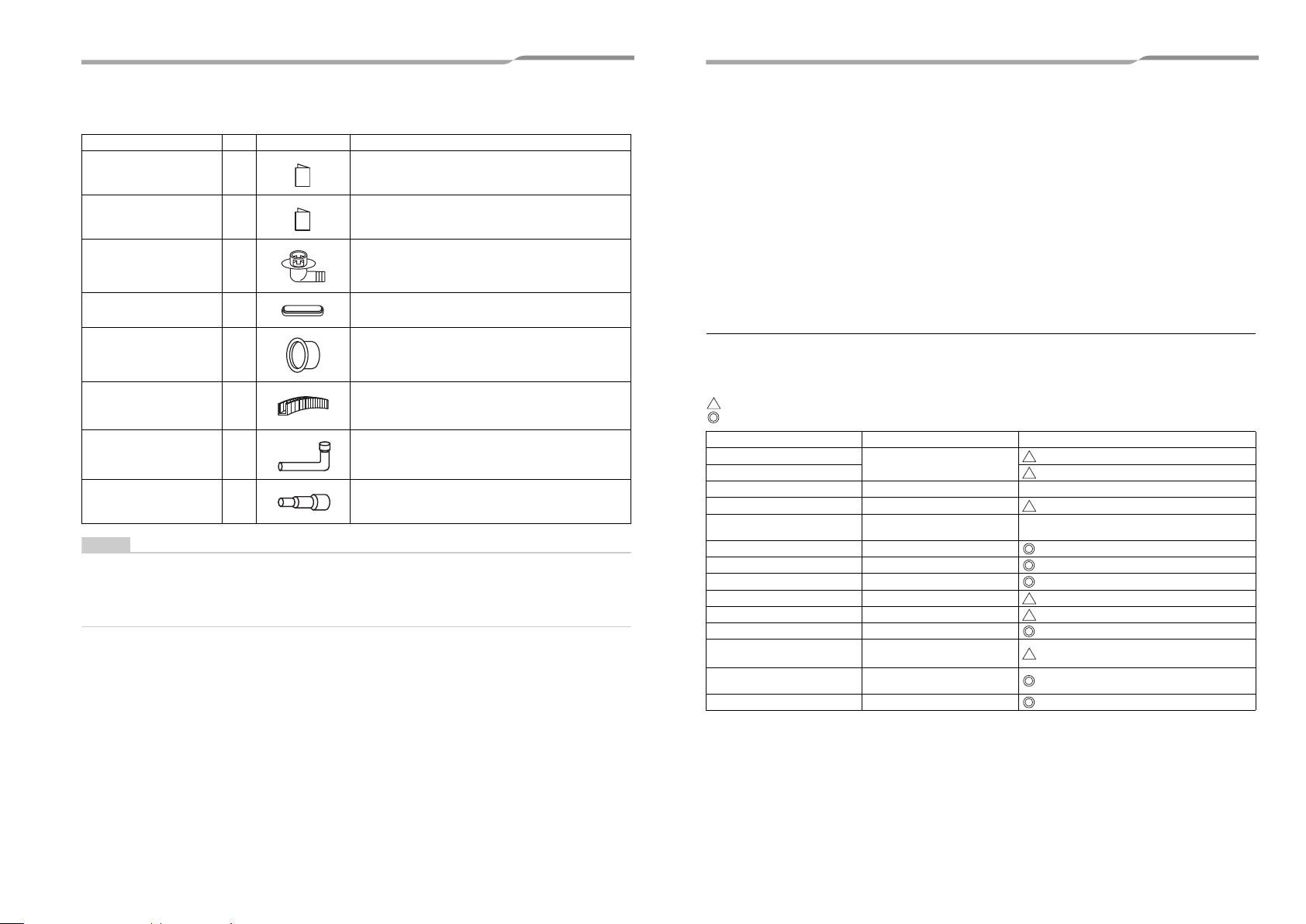
2 Accessory parts
Part name Q’ty Shape Usage
Owner’s Manual 1 Hand this directly to the customer.
Installation Manual 1 Hand this directly to the customer.
Drain nipple 1
Waterproof rubber cap 1
Protective bush 1 For protecting wires (pipe cover)
Guard material for passage
part
Joint pipe (Ø19.1 - Ø22.2) 1
Joint socket (Ø15.9 - Ø22.2) 1
• Before installing the unit, check that the unit has the correct model name to prevent the wrong unit from being installed
in the wrong place.
• Before proceeding to weld the refrigerant pipe, be sure to pass nitrogen through the pipe.
• Before installing the indoor units, read the instructions in the installation manual provided with the indoor units.
• Before installing a branch pipe, read the instructions in the installation manual provided with the branch pipe kit.
1 For protecting passage part (pipe cover)
For the pipe inside the outdoor unit (MCY-MAP0804HT8 / HT7
only)
For the pipe inside the outdoor unit (MCY-MAP0804HT8 / HT7
only)
3 Installation of new refrigerant air
conditioner
This air conditioner adopts the new HFC refrigerant (R410A) which does not deplete the ozone layer.
• R410A refrigerant is vulnerable to impurities such as water, oxidizing membranes, or oils because the pressure
of R410A refrigerant is higher than that of the former refrigerant by approximately 1.6 times.
As well as the adoption of the new refrigerant, the refrigerating oil has been also changed. Therefore, pay
attention so that water, dust, former refrigerant, or refrigerating oil does not enter the refrigerating cycle of the
new refrigerant air conditioner during installation.
• To prevent mixing of refrigerant or refrigerating oil, the size of the charge port of the main unit or connecting
section of the installation tool differs to that of an air conditioner for the former refrigerant.
Accordingly, exclusive tools are required for the new refrigerant (R410A) as shown below.
• For connecting pipes, use new and clean piping materials so that water or dust does not enter.
Required tools and cautions on handling
It is necessary to prepare the tools and parts for installation as described below. The tools and parts which will be
newly prepared in the following items should be restricted to exclusive use.
Explanation of symbols
: Newly prepared (It is necessary to use it exclusively with R410A, separately from those for R22 or R407C.)
: Former tool is available.
Gauge manifold
Charging hose Exclusive to R410A
Charging cylinder Charging refrigerant Unusable (Use the Refrigerant charging balance.)
Gas leak detector Checking gas leak Exclusive to R410A
Vacuum pump Vacuum drying
Vacuum pump with counterflow Vacuum drying R22 (Existing article)
Flare tool Flare processing of pipes Usable by adjusting size
Bender Bending processing of pipes R22 (Existing article)
Refrigerant recovery device Recovering refrigerant Exclusive to R410A
Torque wrench Tightening flare nut Exclusive to Ø12.7 mm and Ø15.9 mm
Pipe cutter Cutting pipes R22 (Existing article)
Refrigerant canister Charging refrigerant
Welding machine / Nitrogen gas
cylinder
Refrigerant charging balance Charging refrigerant R22 (Existing article)
Used tools Usage Proper use of tools / parts
Vacuuming, charging refrigerant
and operation check
Welding of pipes R22 (Existing article)
Exclusive to R410A
Usable if a counter-flow preventive adapter is
attached
Exclusive to R410A
Enter the refrigerate name for identification
5-EN 6-EN
Outdoor Unit
WARNING
CAUTION
WARNING
CAUTION
Installation Manual
Outdoor Unit
Installation Manual
4 Installation conditions
Before installation
Be sure to prepare to the following items before installation.
◆ Airtight test
1 Before starting an airtight test, further tighten the spindle valves on the gas and liquid sides.
2 Pressurize the pipe with nitrogen gas charged from the service port to the design pressure to
conduct an airtight test.
3 After the airtight test is completed, evacuate the nitrogen gas.
◆ Air purge
• To purge air, use a vacuum pump.
• Do not use refrigerant charged in the outdoor unit to purge air. (The air purge refrigerant is not contained in the
outdoor unit.)
◆ Electrical wiring
Be sure to fix the power wires, system interconnecting wires and remote controller wires with clamps so that they
do not come into contact with the cabinet, etc.
◆ Earthing
Make sure that proper earthing is provided.
Improper earthing may cause an electric shock. For details on how to check earthing, contact the dealer who installed
the air conditioner or a professional installation company.
Installation location
Install the outdoor unit properly in a location that is durable enough to support the weight of the outdoor unit.
Insufficient durability may cause the outdoor unit to fall, which may result in injury.
This outdoor unit has a weight of about 125 kg. Pay special attention when installing the unit onto a wall surface.
Do not install the outdoor unit in a location that is subject to combustible gas leaks.
Accumulation of combustible gas around the outdoor unit may cause a fire.
Install the outdoor unit in a location that meets the following conditions after the customer’s consent is
obtained.
• A well-ventilated location free from obstacles near the air intake and air discharge
• A location that is not exposed to rain or direct sunlight
• A location that does not increase the operating noise or vibration of the outdoor unit
• A location that does not produce any drainage problems from discharged water
Do not install the outdoor unit in the following locations.
• A location with a saline atmosphere (coastal area) or one that is full of sulfide gas (hot-spring area) (Special
maintenance is required.)
• A location subject to oil, vapor, oily smoke, or corrosive gases
• A location in which organic solvent is used
• A location where high-frequency equipment (including inverter equipment, private power generator, medical
equipment, and communication equipment) is used
(Installation in such a location may cause malfunction of the air conditioner, abnormal control or problems due
to noise from such equipment.)
• A location in which the discharged air of the outdoor unit blows against the window of a neighboring house
• A location where the operating noise of the outdoor unit is transmitted
• When the outdoor unit is installed in an elevated position, be sure to secure its fixing leg.
• A location in which drain water poses any problems.
• Proper earthing can prevent charging of electricity on the outdoor unit surface due to the presence of a high
frequency in the frequency converter (inverter) of the outdoor unit, as well as prevent electric shock. If the
outdoor unit is not properly earthed, you may be exposed to an electric shock.
• Be sure to connect the earth wire (grounding work).
Incomplete earthing can cause an electric shock.
Do not connect earth wires to gas pipes, water pipes, lightning rods or earth wires for telephone wires.
◆ Test run
Turn on the leakage breaker at least 12 hours before starting a test run to protect the compressor.
Incorrect installation work may result in a malfunction or complaints from customers.
7-EN 8-EN
–4–
EN
Outdoor Unit
CAUTION
500 mm
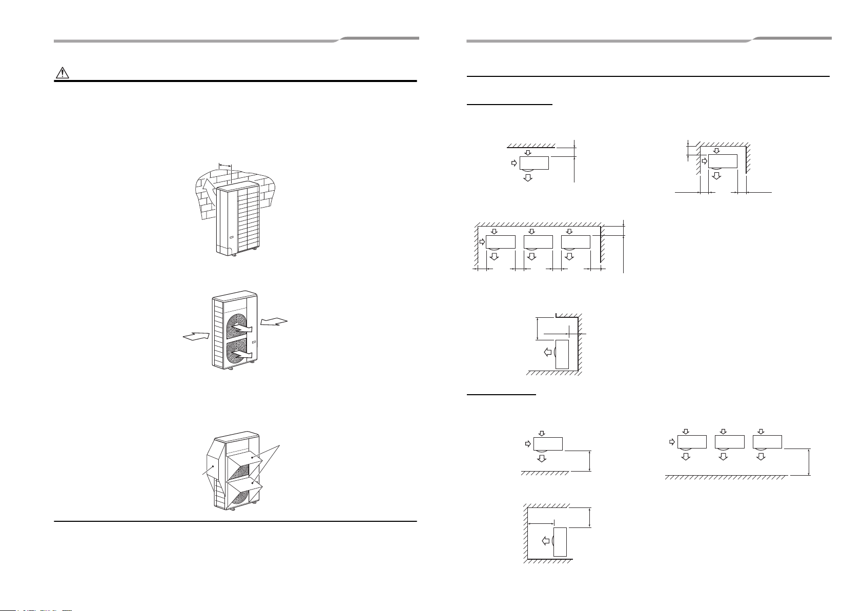
Strong wind
Strong wind
Snow shield
Snow shield
<Example>
150 or more
The height of the obstacle
should be lower than the
height of the outdoor unit.
200 or more
150 or more
250 or more
The height of the obstacle should be lower than
the height of the outdoor unit.
150 or
more
250 or
more
250 or
more
250 or
more
200 or more
500 or more
150 or
more
500 or more
1,000 or
more
1,000 or more
800 or more
Installation Manual
1. Install the outdoor unit in a location where the discharge air is not blocked.
2. When an outdoor unit is installed in a location that is always exposed to strong winds like a coast or on the high
stories of a building, secure normal fan operation by using a duct or wind shield.
3. When installing the outdoor unit in a location that is constantly exposed to strong winds such as on the upper
stairs or rooftop of a building, apply the wind-proofing measures referred to in the following examples.
1) Install the unit so that its discharge port faces the wall of the building.
Keep a distance 500 mm or more between the unit and wall surface.
2) Consider the wind direction during the operational season of the air conditioner, and install the unit so that
the discharge port is set at a right angle relative to the wind direction.
–5–
Outdoor Unit
Installation Manual
Necessary space for installation
Obstacle at rear side
▼ Upper side is free
1. Single unit installation 2. Obstacles on both right and left sides
3. Serial installation of two or more units
▼ Obstacle also above unit
(Unit: mm)
When installing the unit in an area where snowfalls may be heavy, take steps to prevent the unit from being
adversely affected by the fallen or accumulated snow.
• Either make the foundation higher or install a stand (which is high enough to ensure that the unit will be
above the fallen or accumulated snow) and place the unit on it.
• Attach a snow shield (locally procured).
Obstacle in front
▼ Above unit is free
1. Single unit installation 2. Serial installation of two or more units
▼ Obstacle also at the above unit
9-EN 10-EN
Outdoor Unit
150 or
more
1,000
or more
250 or more
250 or
more
1,000
or more
200 or
more
1,000 or
more
300 or
more
1,500 or
more
2,000 or
more
200 or
more
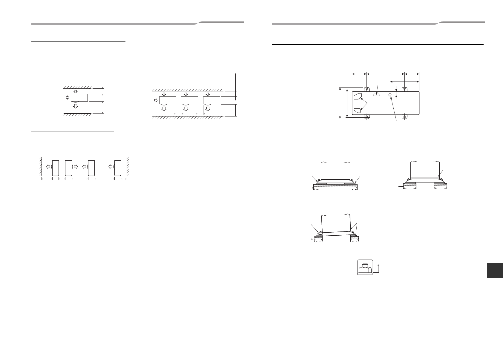
Drain hole
Drain nipple mounting
hole
Knockout
hole
150
600
40
430
400
365
150
GOOD
Fixing leg
Foundation
GOOD
NO GOOD
Foundation
Foundation
If only the end of the
fixing leg is supported,
it may deform.
Do not support the outdoor
unit only with the fixing leg.
Bottom plate of
outdoor unit
Support the bottom surface of the
fixing leg that is in contact with and
underneath the bottom plate of the
outdoor unit.
Absorb vibration with
vibration-proof rubber
pads
15 or less
Installation Manual
Outdoor Unit
Installation Manual
Obstacles in both front and rear of unit
Open above and to the right and left of the unit.
The height of an obstacle in both the front and rear of the unit, should be lower than the height of the outdoor unit.
▼ Standard installation
1. Single unit installation 2. Serial installation of two or more units
Serial installation in front and rear
Open above and to the right and left of the unit.
The height of an obstacle in both the front and rear of the unit should be lower than the height of the outdoor unit.
▼ Standard installation
Installation of outdoor unit
• Before installation, check the strength and horizontalness of the base so that abnormal sounds do not emanate.
• According to the following base diagram, fix the base firmly with the anchor bolts.
(Anchor bolt, nut: M10 x 4 pairs)
• As shown in the figure below, install vibration-proof rubber pads to directly support the bottom surface of the
fixing leg.
* When installing the foundation for an outdoor unit with downward piping, consider the piping work.
Set the out margin of the anchor bolt to 15 mm or less.
11-EN 12-EN
–6–
EN
Outdoor Unit
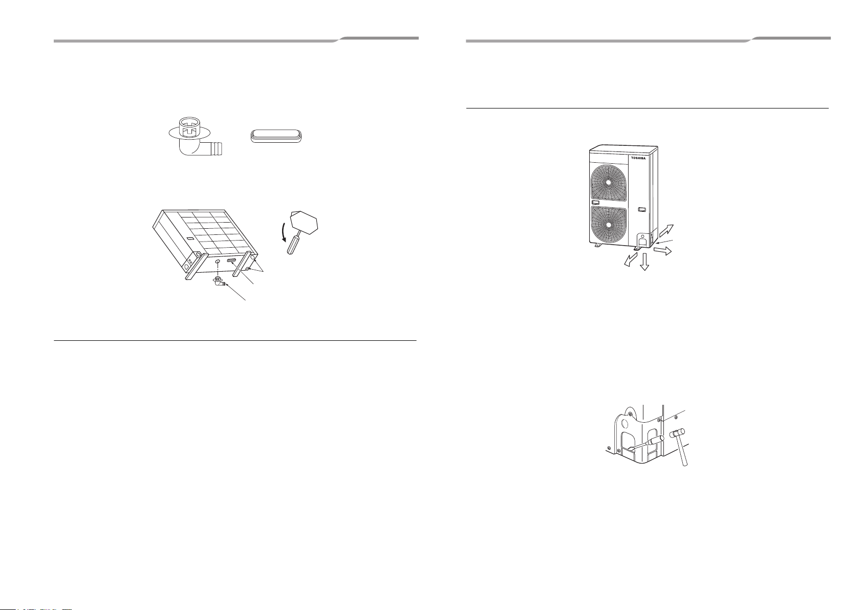
Waterproof rubber cap
Drain nipple
Knockout hole
Waterproof rubber cap
Drain nipple
Rear
Side
Bottom
Pipe cover
Front
Installation Manual
–7–
Outdoor Unit
Installation Manual
• When water is to be drained through the drain hose, attach the following drain nipple and waterproof rubber cap,
and use the drain hose (Inner diam: 16 mm) sold on the market. Also seal the knockout hole and screws securely
with silicone material, etc., to prevent water from leaking.
Some conditions may cause dewing or dripping of water.
• When collectively draining discharged water completely, use a drain pan.
• Please pay attention to the drain in region with snowfall and cold temperature, as it may be frozen and cause
drainage problems. Punch the knockout holes on the bottom plate to improve drainability. Use a screwdriver and
take off the knockout part outward.
For reference
If a heating operation is to be continuously performed for a long time under the condition that the outdoor
temperature is 0 °C or lower, draining defrosted water may be difficult due to the bottom plate freezing, resulting in
trouble with the cabinet or fan.
It is recommended to procure an anti-freeze heater locally in order to safely install the air conditioner.
For details, contact the dealer.
5 Refrigerant piping
Knockout of pipe cover
◆ Knockout procedure
• The indoor / outdoor connecting pipes can be connected in 4 directions.
Take off the knockout of the pipe cover or bottom plate where the pipes or wires will pass through.
• Without detaching the pipe cover, tap on the knockout section a few times with the shank of a screwdriver. A
knockout hole can easily be punched.
• As shown in the figure below, it is easier to punch out the knockout hole when the pipe cover is left in place rather
than when the cover is removed from the unit.
In knocking out the hole, the knockout section can easily be removed by hand once the bottom of the three
locations where the section is joined along the guide lines is broken using a screwdriver.
• After punching out the knockout hole, remove burrs from the hole, and install the protective bush and guard
material around the passage hole provided as accessories in order to protect the wires and pipes. Also be sure
to attach the pipe covers after connecting the pipes. The pipe covers can be easily attached by cutting off the
slits at the lower part of the covers.
* Be sure to wear heavy work gloves while working.
13-EN 14-EN
Outdoor Unit
REQUIREMENT
CAUTION
Obliquity
Roughness
Warp
90°
A
B
REQUIREMENT
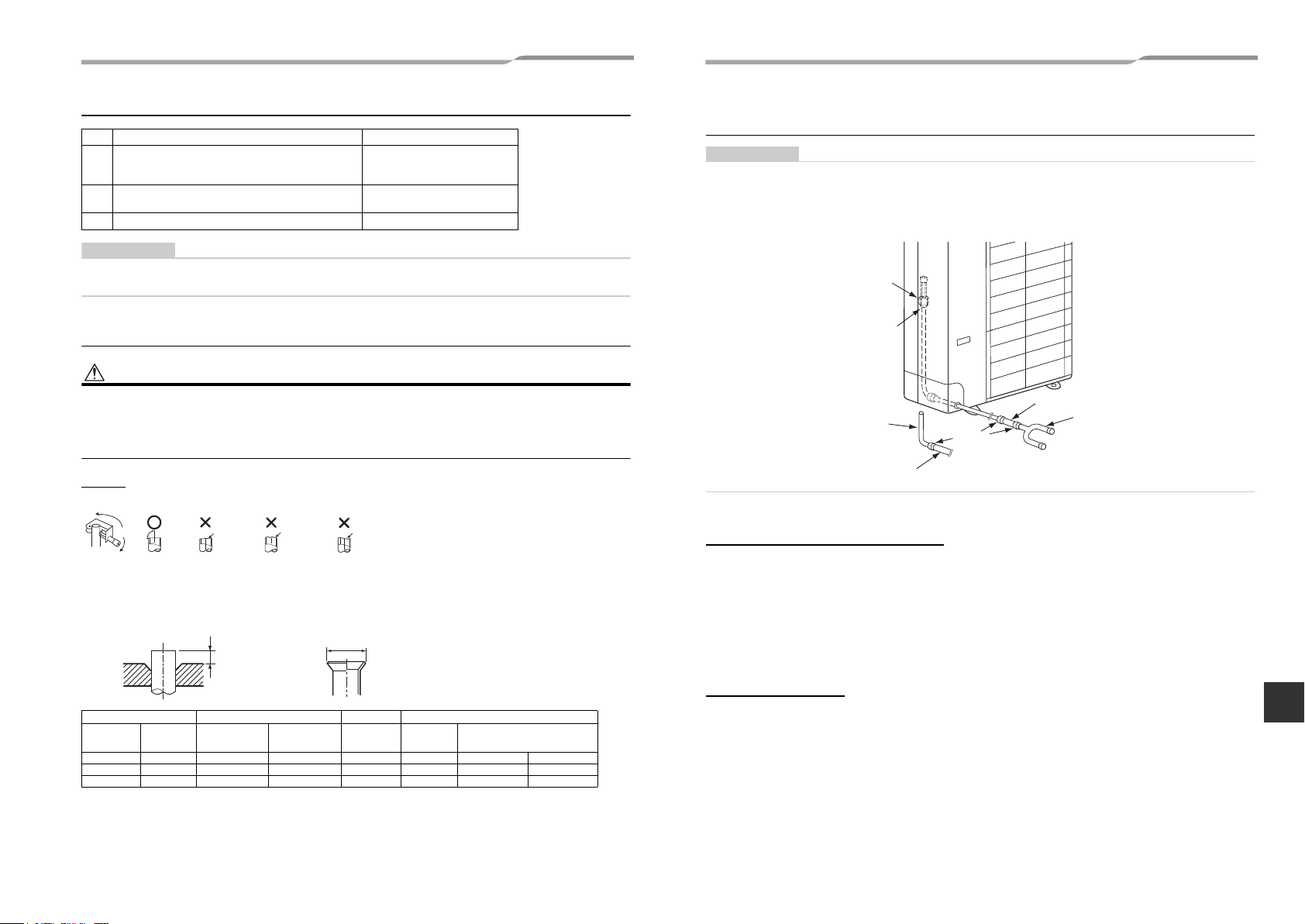
Joint pipe (L-shape, supplied)
Solder
Joint socket (straight, supplied)
Branch pipe
Ø22.2 pipe (locally procured)
Flare connection
Gas side ball valve Ø19.1
Installation Manual
Outdoor Unit
Installation Manual
Optional installation parts (locally procured)
Parts name Q’ty
Refrigerant piping
A
Liquid side: Ø9.5 mm
Gas side: Ø19.1 mm and Ø22.2 mm
Pipe insulating material
B
(polyethylene foam, 10 mm thick)
C Putty, PVC tape One each
Follow the instructions in the installation manual provided with the branch pipe kit and the instructions in the installation
manual of the indoor unit to connect the refrigerant pipe between the branch pipe and indoor unit.
One each
1
Connecting the pipe at the gas side (MCY-MAP0804HT8 / HT7
only)
• Connecting the main pipe (Ø19.1) directly to the gas valve (Ø19.1) may lower the performance.
• To connect the main pipe (Ø22.2) to the gas valve (Ø19.1), use the joint pipe (Ø19.1 - Ø22.2) and joint socket (Ø15.9
- Ø22.2) that come with the outdoor unit.
• Before welding the refrigerant pipe, be sure to pass nitrogen through the pipe to prevent oxidation inside the pipes.
Failure to observe this precaution may cause the refrigerant pipe to become clogged due to oxidation scale.
Refrigerant piping connection
Take note of these 4 important points below for piping work
1. Keep dust and moisture away from inside the connecting pipes.
2. Tightly connect the connection between pipes and the unit.
3. Evacuate the air in the connecting pipes using a VACUUM PUMP.
4. Check for gas leaks at connection points.
Flaring
1. Cut the pipe with a pipe cutter.
◆ Connection procedure
To connect at the front, sides, or back
2. Remove the burr inside of the pipe.
When removing the burr, be careful so that chips do not fall into the pipe.
3. Remove the flare nuts attached to the outdoor / indoor unit, then insert them into each of the pipes.
4. Flare the pipes.
See the following table for the projection margin (A) and flaring size (B).
1 Braze the supplied joint pipe to the main pipe (Ø22.2).
2 Remove the nut from the valve at the gas side, insert the nut into the supplied joint pipe, then flare
the tip of the pipe.
3 Tighten the supplied joint pipe to the valve at the gas side using a nut by the specified torque in
the same direction as removing the outdoor unit pipe.
4 Connect and braze the supplied joint socket between the main pipe (Ø22.2) and branch pipe
(Ø15.9).
To connect downward
15-EN 16-EN
Pipe A B Flare Nut
Outside
diameter
* In case of flaring for R410A with the conventional flare tool, pull the tool out approx. 0.5 mm more than that for
R22 to adjust it to the specified flare size.
The copper pipe gauge is useful for adjusting the projection margin size.
Thickness
mm mm mm mm mm mm N•m kgf•m
9.5 0.8 0 to 0.5 1.0 to 1.5 13.2 22 33 to 42 3.3 to 4.2
19.1 1.2 0 to 0.5 1.0 to 1.5 24.0 36 100 to 120 10.0 to 12.0
Rigid
(clutch type)
R410A tool
Imperial
(wing nut type)
R410A tool
Width across
flat
Tighten torque
1 Cut the supplied joint pipe, then braze the main pipe (Ø22.2).
2 Remove the nut from the valve at the gas side, insert the nut into the supplied joint pipe, then flare
the tip of the pipe.
3 Tighten the supplied joint pipe to the valve at the gas side using a nut by the specified torque.
4 Connect and braze the supplied joint socket between the main pipe (Ø22.2) and branch pipe
(Ø15.9).
–8–
EN
Outdoor Unit
CAUTION
Internally
threaded side
Externally
threaded side
Flare nut
Tighten with torque
wrench.
Fix with wrench.
Half union or packed valve
Piping valve
Cap
Cover
Flare nut
Loosened
Valve at gas side
Tightened
Cap
Cover
NO GOOD
G
ØF
+0.04
-0.02
+0.04
-0.02
+0.04
-0.02
+0.04
-0.02
+0.03
-0.03
+0.03
-0.03
Installation Manual
–9–
Outdoor Unit
Installation Manual
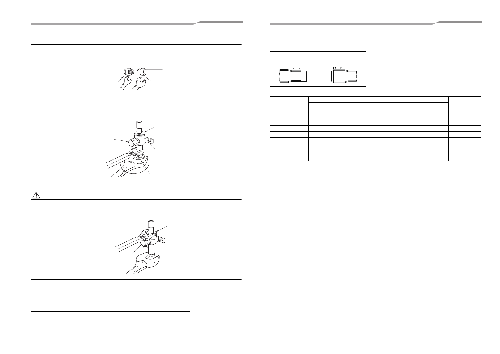
Tightening of connecting part
1. Align the centers of the connecting pipes and fully tighten the flare nut with your fingers. Then fix the nut with a
wrench as shown in the figure and tighten it with a torque wrench.
2. As shown in the figure, be sure to use two wrenches to loosen or tighten the flare nut of the valve on the gas
side. If you use a single wrench, the flare nut cannot be tightened to the required tightening torque.
On the other hand, use a single wrench to loosen or tighten the flare nut of the valve on the liquid side.
1.Do not put the wrench on the cap or cover.
The valve may break.
2.If applying excessive torque, the nut may break according to some installation conditions.
Coupling size of brazed pipe
Connected section
External size Internal size
K
ØC
Connected section
Standard outer dia.
of connected
copper pipe
6.35 6.35 (±0.03) 6.45 ( ) 7 6 0.06 or less 0.50
9.52 9.52 (±0.03) 9.62 ( ) 8 7 0.08 or less 0.60
12.70 12.70 (±0.03) 12.81 ( ) 9 8 0.10 or less 0.70
15.88 15.88 (±0.03) 16.00 ( ) 9 8 0.13 or less 0.80
19.05 19.05 (±0.03) 19.19 ( ) 11 10 0.15 or less 0.80
22.22 22.22 (±0.03) 22.36 ( ) 11 10 0.16 or less 0.82
External size Internal size
Standard outer dia.
(Allowable difference)
Min. depth of
insertion
CFKG
Oval value
(Unit: mm)
Min. thickness
of coupling
• After the installation work, be sure to check for gas leaks of the pipe connections with nitrogen.
• Pressure of R410A is higher than that of R22 (Approx. 1.6 times).
Therefore, using a torque wrench, tighten the flare pipe connecting sections that connect the indoor / outdoor
units at the specified tightening torque.
Incomplete connections may cause not only a gas leak, but also trouble with the refrigeration cycle.
Do not apply refrigerant oil to the flared surface.
17-EN 18-EN
 Loading...