

Engineering Data Book
File No. E06-311


The engineering data book details all relevant data, charts and drawings to
enable you to get the best performance from the Toshiba Mini-SMMS for various
applications.
The information is aimed to assist you by providing greater system details and
the wider applications that system covers.
It is recommended that the data book be used in accordance with the following
as references.
Design manual: File No.A06-111
Installation manual: File No.A06-211
Service manual: File No.A05-016
1
-1
Contents
1. Forward ...................................................................................................................... 1-1
2. Contents .................................................................................................................... 2-1
3. Introduction ............................................................................................................... 3-1
4. System overview ....................................................................................................... 4-1
4-1. Summary of system equipments ....................................................................... 4-1
4-2. Outdoor units .................................................................................................... 4-2
4-3. Indoor units ....................................................................................................... 4-3
4-4. Branching joints and headers ........................................................................... 4-5
4-5. PMV Kit............................................................................................................. 4-5
4-6. Remote controller ............................................................................................. 4-6
5. Capacity compensation chart .................................................................................. 5-1
6. Piping requirements ................................................................................................. 6-1
7. Refrigerant cycle diagram ........................................................................................ 7-1
8. Wiring guideline ........................................................................................................ 8-1
9. Indoor unit line up ..................................................................................................... 9-1
9-1. 4-way Air Discharge Cassette Type ............................................................... 9-1-1
9-2. Compact 4-way Cassette (600 × 600) Type ................................................... 9-2-1
9-3. 2-way Air Discharge Cassette Type ............................................................... 9-3-1
9-4. 1-way Air Discharge Cassette Type (Included NewType) .............................. 9-4-1
9-5. Concealed Duct Standard Type ..................................................................... 9-5-1
9-6. Slim Duct Type ............................................................................................... 9-6-1
9-7. Concealed Duct High Static Pressure Type ................................................... 9-7-1
9-8. Under Ceiling Type ........................................................................................ 9-8-1
9-9. High Wall (1 series) Type ............................................................................... 9-9-1
9-10. High Wall (2 series) Type ............................................................................. 9-10-1
9-11. Floor Standing Cabinet Type ....................................................................... 9-11-1
9-12. Floor Standing Concealed Type .................................................................. 9-12-1
9-13. Floor Standing Type ..................................................................................... 9-13-1
9-14. Optional parts of indoor units ....................................................................... 9-14-1
10. PMV Kit .................................................................................................................... 10-1
11. Outdoor unit ............................................................................................................ 11-1
12. Controls ................................................................................................................... 12-1
2
-1

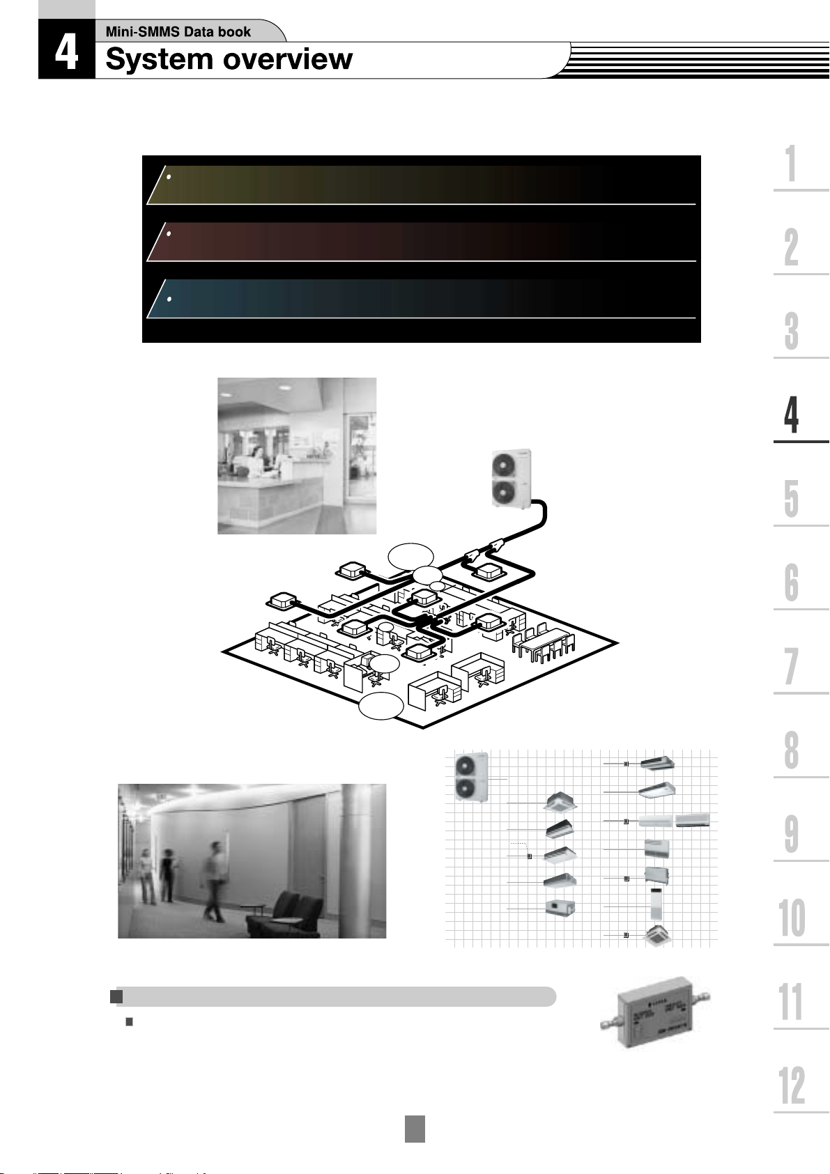
Mini-SMMS Data book
3
Introduction
Toshiba MiNi-SMMS Air Conditioning
Greater Flexibility for Even More Comfort
• Superior new Toshiba VRF system for small and mid-sized buildings
• Toshiba’s innovative spirit — concept of VRF, all advantages of SMMS
World’s best class energy savings
• World-class energy savings — COP of 4.61* achieved by Toshiba’s
unrivalled SMMS technologies and newly developed components
*4HP CDU system
Flexible and easy installation
• Greater application versatility—13 types of indoor units for use in up to 9
rooms; max. 6 HP
• Small and light weight outdoor unit
• Total piping length 180 m* (forthest 100 m)
• Maximum height variation for indoor units
(Outdoor unit is up to 30 m higher than indoor unit / outdoor unit is up to 20 m lower than indoor unit)
*150 m with PMV kit
1
2
3
4
5
Pursue unexpected quieter operation
• Quiet operation enables a tranquil interior environment, which can be
further enhanced with our optional PMV* kit
• Product made from quieter outdoor unit by adoption of Bat wing fan
*Pulse Motor Valve
6
7
8
9
10
11
12
3
-1
3
Introduction
World’s best class energy savings
World-class energy savings — COP of 4.61* achieved by Toshiba’s unrivalled
1
SMMS technologies and newly developed components
*4HP CDU system
2
3
4
5
6
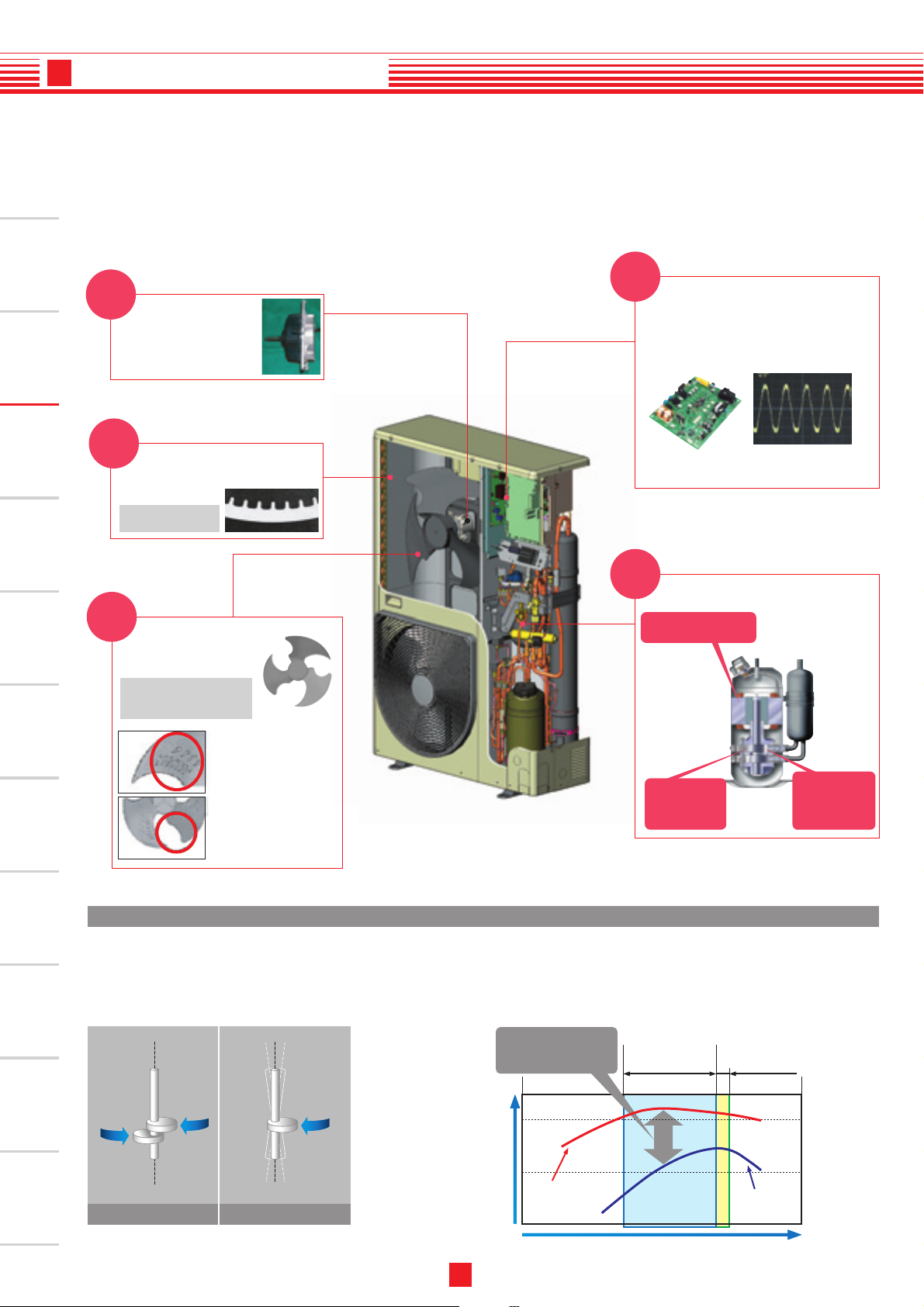
New
DC fan motor
• High output / high
efficiency DC motor
• 600W output
• Sine wave drive
New
Heat exchanger
High-efficiency R410A
heat-transfer tube
Configuration of the finned
heat-transfer tube
New
Bat wing fan
New development for high
pressure low sound fan
→
The bat wing fan realizes
the sound level equivalent
to current model.
New
Vector-controlled inverter
Vector IPDU control changes motor current
wave to a smooth sinusoidal pattern so that
noise emitted from the drive units is greatly
reduced.
Efficient circuit built-in
and new PIM adoption
Smooth sign curve liquid
realizes efficient-izing and
low noise-ization.
New
Twin-rotary DC compressor
Greater motor efficiency
from improved coil design
7
8
9
10
11
Anti-eddy projection
Anti-eddy projection prevents
big eddies and reduces air
resistance.
Reverse-arc-shape wing
Reverse-arc-shape wing
reduces air resistance.
DC twin rotary compressor (A3 comp) features
High reliability
The enhanced DC twin-rotary compressor delivers stable performance with minimum friction:
Ideal for noise-sensitive applications. The outdoor unit is almost imperceptible.
TWIN-ROTARY COMPRESSOR
• Low vibrations
• Super-quiet
operation
• High reliability
Comparison of DC twin rotary and Scroll compressor
This difference is the
reason for actual energy
savings
(%)
More effective
compression from
high-precision
components
Partial load range
*Most frequent operation
Nominal range
Higher refrigerant
compression from
redesigned
compression
channels
12
Toshiba Twin-Rotary
Traditional Compressor
DC Twin
Total efficiency of
compressor
rotary type
Frequency of compressor (rps)
3
-2
Conventional
Scroll type
3
Introduction
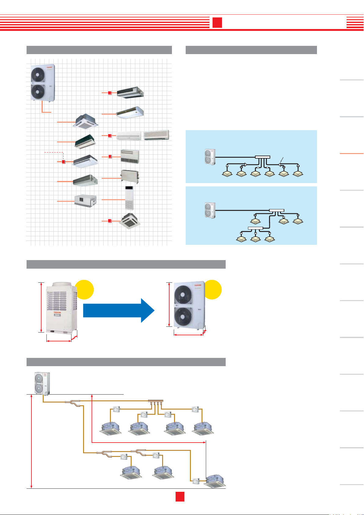
Expansive variety in our line-up of indoor units Shortest route design by free branching
Combination of line and header branching is highly
flexible, allowing the shortest route possible thereby
saving on installation time and costs. Line/header
branching after header branching is only available
with TOSHIBA.
1
PMV-Kit
Small and lightweight
New compact 4-way
cassette
- Line branching
- Header branching
- Line + Header branching
Line branching after header branching
Outdoor unit
Header
Indoor unit
Br
anching joint
PMV kit
2
3
4
Header branching after header branching
Outdoor unit
Header
5
Header
Indoor unit
PMV kit
6
Mini-SMMS outdoor unitSuper-MMS outdoor unit
1,800 mm
990 mm
Piping length
Compact
Mini-SMMS is born from
our supreme VRF technology
750 mm
Best-in-class piping length and height
1,340 mm
900 mm
117kg228kg
1-phase3-phase
320 mm
7
8
9
10
11
3
(Revised edition in 7.Apr.2006)
-3
12
3
Introduction
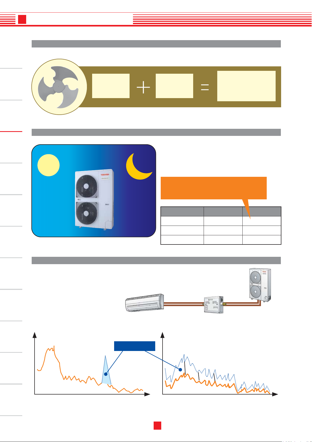
Quieter with smoother wind flow
1
Bat Wing fan
2
3
4
5
6
Night operation mode
Day
Day
New bat
wing fan
Night
Night
DC fan
motor
Mi ni-SMMS ha s ti med , Night O peration , allowing
queter operation at night.
(A timer or a switch is local arrangements)
Clears nighttime residential noise ordinances.
Can be used without obstructing peaceful
neighborhoods at night.
Outdoor unit
4HP
Quiet er sound
and
power saving
Daytime Night
49dB
46dB
7
8
9
10
11
5HP
6HP
PMV kit
P M V k it (R B M- PM V0 3 61 E/ RB M -
PMV0 901E) sh all be re quired f or
q ui t e r p la c e a pp l ic a t io n a s an
optional to reduce refrigerant sound
especially in oil retrieval control or
in transient operation as start up.
Suppress particular-Hz noise away Suppress overall noise levels
Die-away Zone
50dB
51dB
46 dB
47dB
12
(Hz) (Hz)
3
(Revised edition in 7.Apr.2006)
-4

4-1. Summary of system equipments
World-class energy savings_COP of 4.61* achieved by Toshiba’s unrivalled
S-MMS technologies and newly developed components
Quiet operation can be further enhanced with an optional PMV
(flow regulating valve) Kit.
Versatile application_13 types of indoor units for use in up to 9 rooms (6 HP)
Sales launch scheduled for early 2006. Specifications differ by region.
For questions regarding availability, please contact your local distributor.
4HP CDU system
*
Pulse Motor Valve
*
Use of quieter place
Necessity of PMV Kit (RBM-PMV0361E / RBM-PMV0901E) for
quieter place application as an optional.
4
-1
PMV Kit
New compact 4-way
cassette
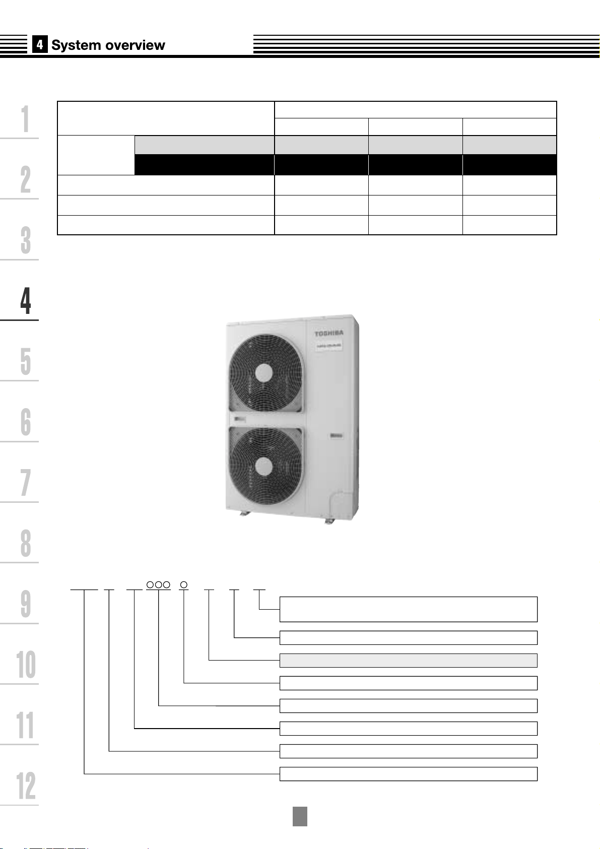
4-2. Outdoor units
Corresponding HP
Model
name
Heat pump(50Hz) MCY-
Heat pump(60Hz) MCY-
Cooling capacity(kW)*1
Heating capacity(kW)*1
No.of connectable indoor units
*1 Rated conditions
Cooling:Indoor air temperature 27
Heating:Indoor air temperature 20
Inverter unit
4HP 5HP 6HP
MAP0401HT MAP0501HT MAP0601HT
MAP0401HT2D MAP0501HT2D MAP0601HT2D
12.1
12.5
6
o
C DB/19oCWB,Outdoor air temperature 35oCDB
o
C DB,Outdoor air temperature 7oCDB/6oCWB
14.0
16.0
8
15.5
18.0
9
Allocation standard of model name
MCY- 2DMAP H T
No mark: Power supply specification, 1O/220-240V, 50Hz
2D : Power supply specification, 1
T : Inverter unit
H : Heat pump
Development Number
Capacity rank HP x 10
R410A
M : Individual unit
Multi Compact Type
4
-2
O
220V, 60Hz
/
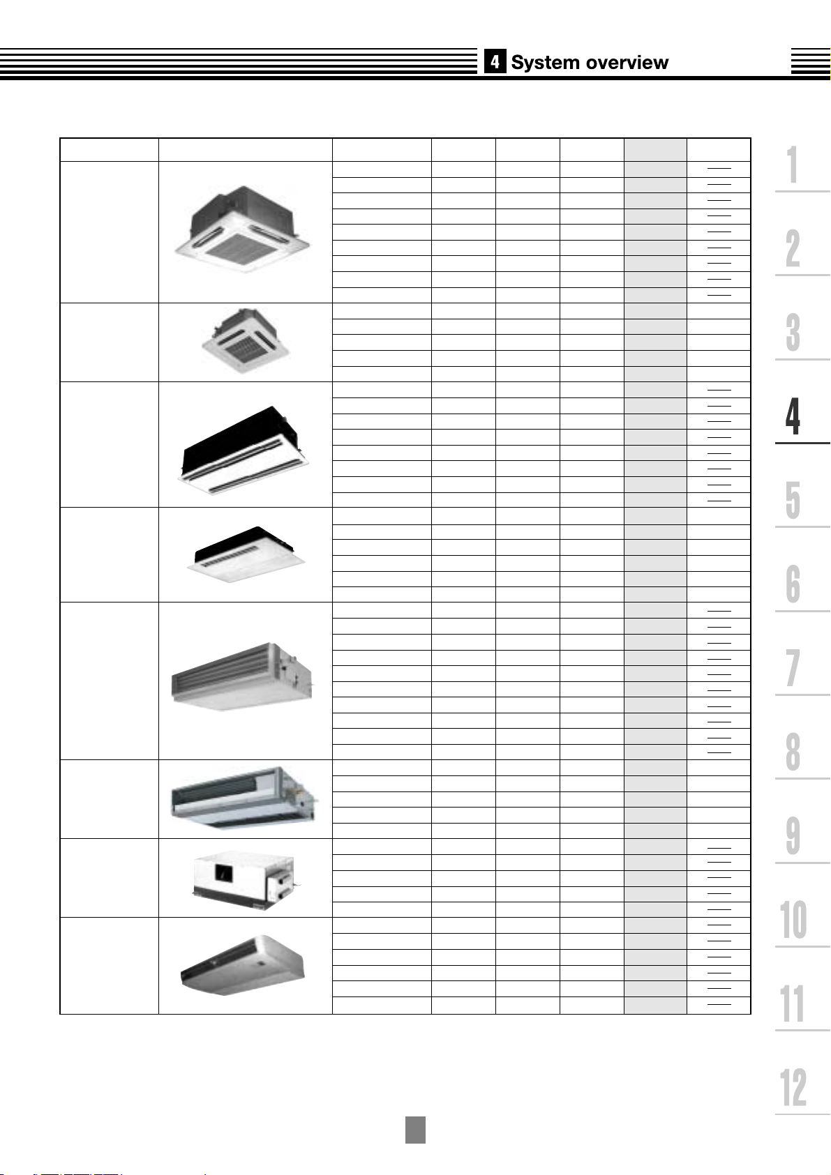
4-3. Indoor units
Type
4-way Air Discharge
Cassette Type
Compact 4-way
Air Discharge
(600x600) Type
2-way Air Discharge
Cassette Type
1-way Air Discharge
Cassette Type
Concealed Duct
Standard Type
Slim Duct Type
Concealed Duct
High Static
Pressure Type
Under Ceilling Type
Appearance
Model name
MMU-AP0091H
MMU-AP0121H
MMU-AP0151H
MMU-AP0181H
MMU-AP0241H
MMU-AP0271H
MMU-AP0301H
MMU-AP0361H
MMU-AP0481H
MMU-AP0071MH
MMU-AP0091MH
MMU-AP0121MH
MMU-AP0151MH
MMU-AP0181MH
MMU-AP0071WH
MMU-AP0091WH
MMU-AP0121WH
MMU-AP0151WH
MMU-AP0181WH
MMU-AP0241WH
MMU-AP0271WH
MMU-AP0301WH
MMU-AP0071YH
MMU-AP0091YH
MMU-AP0121YH
MMU-AP0152SH
MMU-AP0182SH
MMU-AP0242SH
MMD-AP0071BH
MMD-AP0091BH
MMD-AP0121BH
MMD-AP0151BH
MMD-AP0181BH
MMD-AP0241BH
MMD-AP0271BH
MMD-AP0301BH
MMD-AP0361BH
MMD-AP0481BH
MMD-AP0071SPH
MMD-AP0091SPH
MMD-AP0121SPH
MMD-AP0151SPH
MMD-AP0181SPH
MMD-AP0181H
MMD-AP0241H
MMD-AP0271H
MMD-AP0361H
MMD-AP0481H
MMC-AP0151H
MMC-AP0181H
MMC-AP0241H
MMC-AP0271H
MMC-AP0361H
MMC-AP0481H
Capacity rank
009 type
012 type
015 type
018 type
024 type
027 type
030 type
036 type
048 type
007 type
009 type
012 type
015 type
018 type
007 type
009 type
012 type
015 type
018 type
024 type
027 type
030 type
007 type
009 type
012 type
015 type
018 type
024 type
007 type
009 type
012 type
015 type
018 type
024 type
027 type
030 type
036 type
048 type
007 type
009 type
012 type
015 type
018 type
018 type
024 type
027 type
036 type
048 type
015 type
018 type
024 type
027 type
036 type
048 type
Capacity
code
1.00
1.25
1.70
2.00
2.50
3.00
3.20
4.00
5.00
0.80
1.00
1.25
1.70
2.00
0.80
1.00
1.25
1.70
2.00
2.50
3.00
3.20
0.80
1.00
1.25
1.70
2.00
2.50
0.80
1.00
1.25
1.70
2.00
2.50
3.00
3.20
4.00
5.00
0.80
1.00
1.25
1.70
2.00
2.00
2.50
3.00
4.00
5.00
1.70
2.00
2.50
3.00
4.00
5.00
Cooling
capacity (kW)
2.8
3.6
4.5
5.6
7.1
8.0
9.0
11.2
14.0
2.2
2.8
3.6
4.5
5.6
2.2
2.8
3.6
4.5
5.6
7.1
8.0
9.0
2.2
2.8
3.6
4.5
5.6
7.1
2.2
2.8
3.6
4.5
5.6
7.1
8.0
9.0
11.2
14.0
2.2
2.8
3.6
4.5
5.6
5.6
7.1
8.0
11.2
14.0
4.5
5.6
7.1
8.0
11.2
14.0
Heating
capacity (kW)
3.2
4.0
5.0
6.3
8.0
9.0
10.0
12.5
16.0
2.5
3.2
4.0
5.0
6.3
2.5
3.2
4.0
5.0
6.3
8.0
9.0
10.0
2.5
3.2
4.0
5.0
6.3
8.0
2.5
3.2
4.0
5.0
6.3
8.0
9.0
10.0
12.5
16.0
2.5
3.2
4.0
5.0
6.3
6.3
8.0
9.0
10.0
16.0
5.0
6.3
8.0
9.0
12.5
16.0
PMV Kit
Available
Available
Available
Available
Available
Available
Available
Available
Available
Available
Available
Available
Available
Available
Available
Available
4
-3
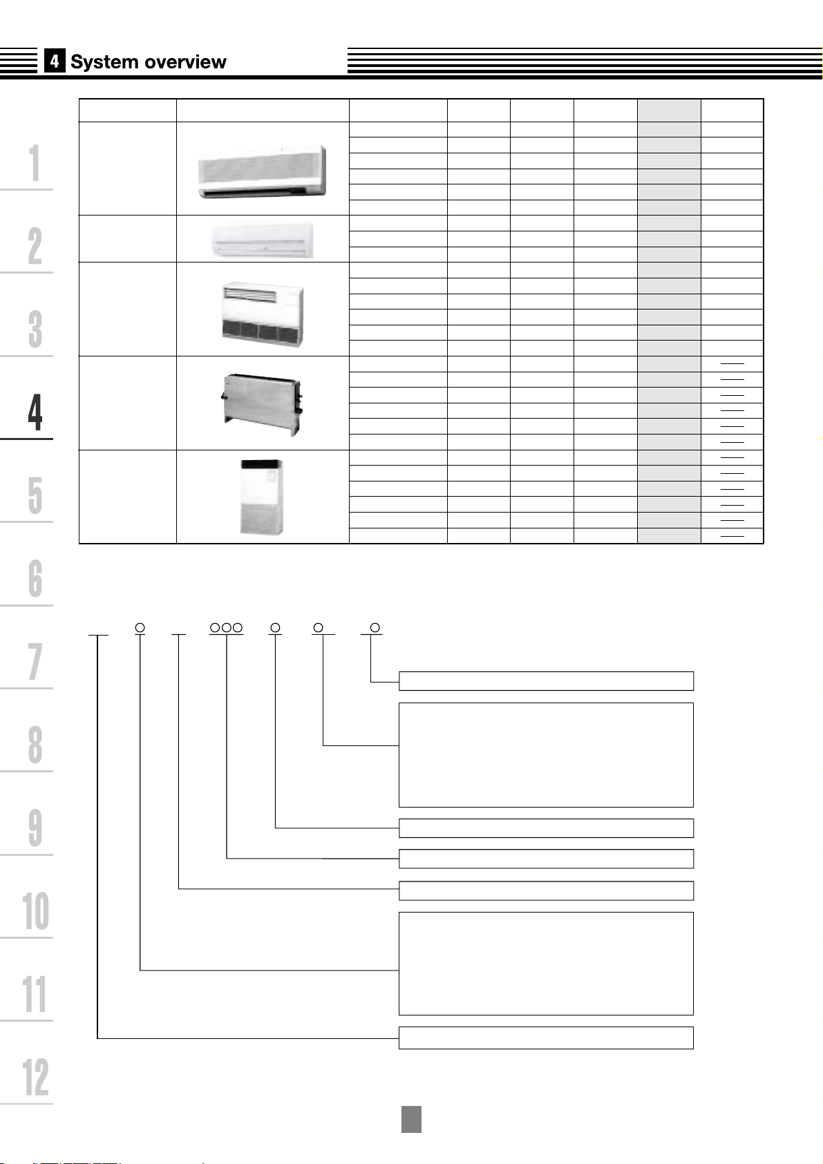
Type Appearance Model name
High Wall Type
(1 series)
High Wall Type
(2 series)
Floor Standing
Cabinet Type
Floor Standing
Concealed Type
Floor Standing Type
MMK-AP0071H
MMK-AP0091H
MMK-AP0121H
MMK-AP0151H
MMK-AP0181H
MMK-AP0241H
MMK-AP0072H
MMK-AP0092H
MMK-AP0122H
MML-AP0071H
MML-AP0091H
MML-AP0121H
MML-AP0151H
MML-AP0181H
MML-AP0241H
MML-AP0071BH
MML-AP0091BH
MML-AP0121BH
MML-AP0151BH
MML-AP0181BH
MML-AP0241BH
MMF-AP0151H
MMF-AP0181H
MMF-AP0241H
MMF-AP0271H
MMF-AP0361H
MMF-AP0481H
Capacity
rank
007 type
009 type
012 type
015 type
018 type
024 type
007 type
009 type
012 type
007 type
009 type
012 type
015 type
018 type
024 type
007 type
009 type
012 type
015 type
018 type
024 type
015 type
018 type
024 type
027 type
036 type
048 type
Capacity
code
0.80
1.00
1.25
1.70
2.00
2.50
0.80
1.00
1.25
0.80
1.00
1.25
1.70
2.00
2.50
0.80
1.00
1.25
1.70
2.00
2.50
1.70
2.00
2.50
3.00
4.00
5.00
Cooling
capacity (kW)
2.2
2.8
3.6
4.5
5.6
7.1
2.2
2.8
3.6
2.2
2.8
3.6
4.5
5.6
7.1
2.2
2.8
3.6
4.5
5.6
7.1
4.5
5.6
7.1
8.0
11.2
14.0
Heating
capacity (kW)
2.5
3.2
4.0
5.0
6.3
8.0
2.5
3.2
4.0
2.5
3.2
4.0
5.0
6.3
8.0
2.5
3.2
4.0
5.0
6.3
8.0
5.0
6.3
8.0
9.0
10.0
16.0
PMV Kit
Available
Available
Available
Available
Available
Available
Available
Available
Available
Available
Available
Available
Available
Available
Available
Allocation standard of model name
MM
--AP H
C : China model
M : Compact 4-way Cassete Type
W : 2-way Cassete Type
S : 1-way Cassete Type
Y : Small sized 1-way Cassete Type
B : Built-in Type (Built-in Duct Type)
(Floor concealed Type)
SP(S) : Slim Duct Type
Development series No.
Based on the cooling capacity (Btu/h)/1,000
R410A
U : Cassette Type
D : Duct Type
C : Under Ceiling Type
K : High Wall Type
L : Floor Type (Cabinet type)
(Concealed type)
F : Floor Standing Type
MM : Modular Multi Type
4
-4
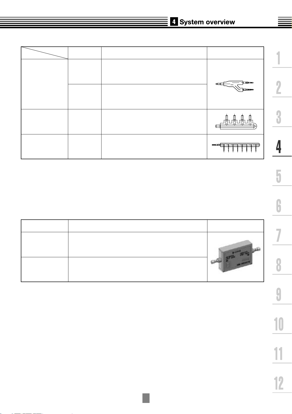
4-4. Branching joints and headers *1
Model name
RBM-BY53E
Y-shape branching joint
RBM-BY103E
4-branching header
8-branching header
*1 If total capacity code value of indoor unit exceeds that of outdoor unit, apply code of outdoor unit.
*2 "capacity code" can be obtained from page~. (capacity code is not actual capacity)
*3 When using Y-shape branching joint for 1st branching, select according to the capacity code of outdoor unit.
RBM-HY1043E
RBM-HY1083E
Indoor unit capacity code (*2) :Total below 6.4
Indoor unit capacity code (*2) :Total 6.4 or more
and below 7.8
Indoor unit capacity code (*2) :Total below 7.8
Indoor unit capacity code (*2) :Total below 7.8
Usage Appearance
4-5. PMV Kit
Model name
RBM-PMV0361E
RBM-PMV0901E
For more information see Chapter 10.
Indoor unit capacity type Appearance
007, 009, 012 type
015, 018, 024 type
4
-5
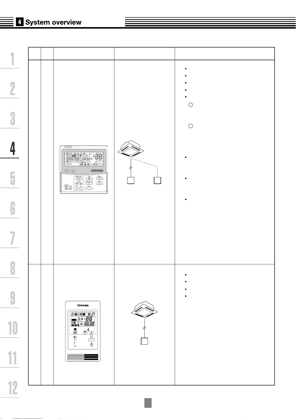
4-6. Remote controller
Name
Model
name
Appearance Application Function
RBC-AMT31E
Wired remote controllerSimple wired remote controller
Connected to indoor unit
Wired remote
controller
Wired remote
controller
(In case of control
by 2 remote
controllers)
Start / Stop
Mode Change
Temperature setting
Fan speed
Timer function
1
On or off elapsed timer
with 30 minite increments.
Automatic off function
2
Weekly when combined with
RBC-EXW21E2
weekly schedule operation can
be operated.
Filter dirty indicator
Displays automatically maintenance
time of indoor filter by flashes.
Self-diagnosis function
Pressing "CHECK" button
displays status code.
Control by 2 remote controllers is
available.
Two remote controllers can be
connected to one indoor unit.
The indoor unit can be separately
operated from a different location.
TEST
SETTING
RBC-AS21E2
Connected to indoor unit
ûC
ûF
Simple remote controller
4
-6
Start / Stop
Temperature setting
Change of air flow
Check code display
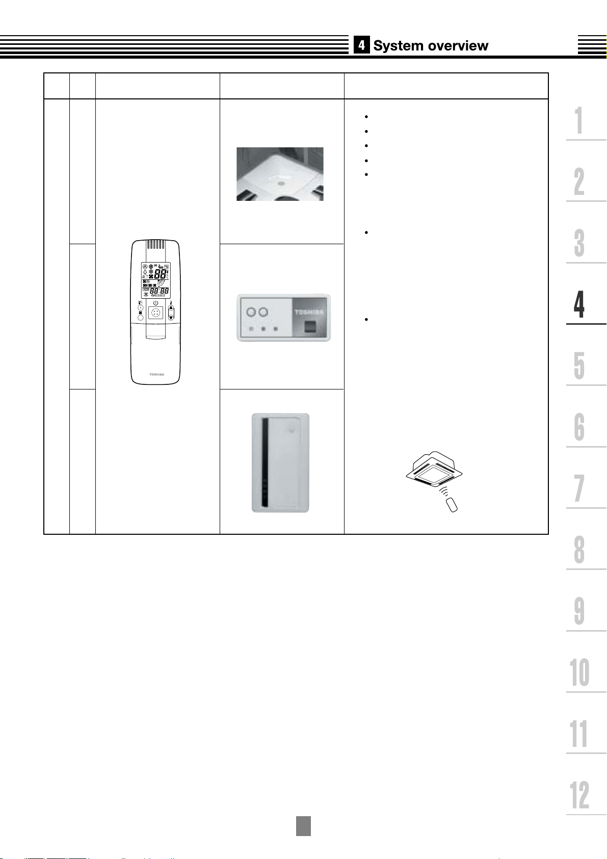
Name
Model
name
Appearance Function
Wireless remote controller kit
Start / Stop
Mode change
Temperature setting
Change of air flow
Timer function
On or off timer operation, setting in
30 minute increments.
Automatic Off function
Control by 2 remote controllers is
available.
Two wireless remote controllers can
operate one indoor unit. The indoor unit
can be separately operated from a
different location.
Check code display
TCB-AX21U(W)-E2
(for 4-way airdischarge cassette)
RBC-AX22CE2
(for under ceiling)
TCB-AX21-E2
(for other units except for the con-
cealed duct high static pressure)
TCB-AX21E2 RBC-AX22CE2 TCB-AX21U(W)-E2
4
-7
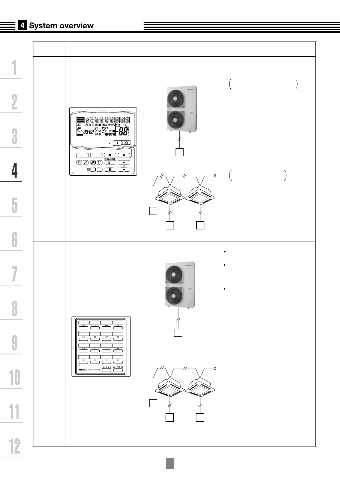
Name
Model
name
Appearance Application Performance
ZONE
ALL
ZONE
GROUP
1234
SET DATA
SETTING
SELECT ZONE
TCB-SC642TLE2
TEST
UNIT No.
No.
R.C.
SET
CL
Central remote controller
GROUP
CODE
No.
Connected to outdoor unit,
or indoor unit
Outdoor
unit
Central
remote controller
Central
remote
controller
Indoor
remote controller
Individual control up to 64 indoor units.
Individual control for max. 64 indoor
units divided into 4 zones.
Up to 16 indoor units for each
zone
Up to 16 outdoor units are
connectable.
Four selectable central control settings to
restrict individual remote controller
operations.
Setting for one of 1 to 4 zones is
available.
Can be used with other central control
devices (Up to 10 central control
devices with in one control circuit)
Two selectable control modes
Central controller mode
Remote controller mode
Setting of simultaneous ON/OFF 3
times for each day of the week
combined with a weekly timer.
TCB-CC163TLE2
ON-OFF controller
Connected to outdoor unit,
or indoor unit
Outdoor unit
ON-OFF
controller
Indoor unit
ON-OFF
controller
Indoor
remote controller
Individual control up to 16 indoor units.
Setting of simultaneous ON-OFF 3
times for each day of the week when
combined with a weekly timer.
Connected to 2 remote controllers is
possible.
4
-8
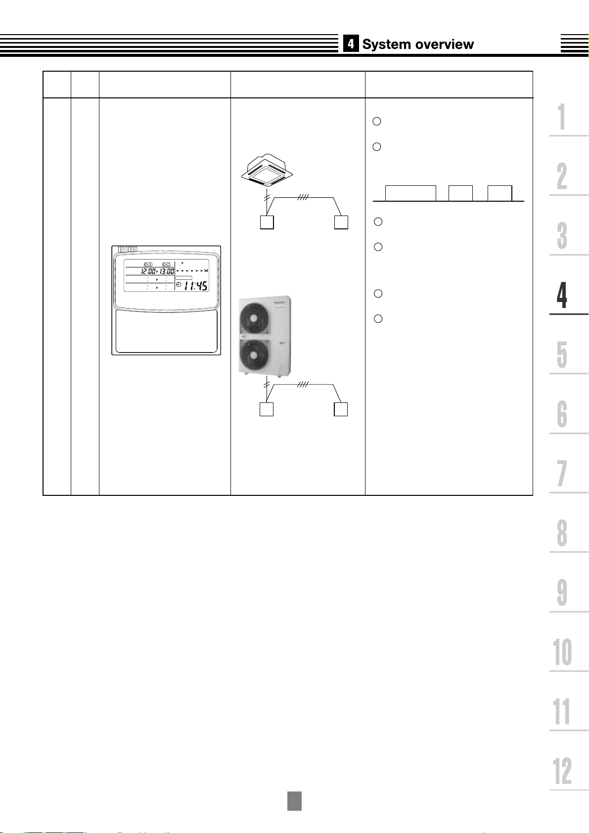
Name
Model
name
Appearance Application Performance
Weekly timer
RBC-EXW21E2
PROGRAM1
PROGRAM2
PROGRAM3
WEEKLY TIMER
SuMoTuWeThFr Sa
ERROR
Connected to central
remote controller or
wired remote controller
Wired
remote controller
Outdoor unit
Weekly
timer
Weekly schedule operation
1
Setting different start / stop time for each
day of the week
2
ON / OFF can be set 3 times
a day.
ON
8:00 12:00 13:00 18:00 19:00 21:00
3
"CHECK" "PROGRAM" "DAY"
OFF ON OFF ON OFF
button copying of settings easy.
4
Two different schedules for a
week can be specified.
(Summer schedule and winter
schedule, etc.)
5
"CANCEL" "DAY" button enables
holiday setting.
6
If power supply fails, the setting
contents are stored in the memory for
100 hours.
Central
remote controller
Weekly
timer
4
-9
For indoor unit, the capacity code is decided for each capacity rank.
1
Capacity rank type
Capacity code
NOTE :
Capacity rank : Correspondence to Btu/h. Capacity code : Correspondence to Horsepower.
For outdoor unit, maximum No. of connectable indoor units and total capacity code of indoor units
2
007
0.8
009
1
012
1.25
015
1.7
018
2
024
2.5
027
3
030
3.2
036
4
are decided.
Outdoor unit
MCY-MAP0401HT
MCY-MAP0401HT2D
MCY-MAP0501HT
MCY-MAP0501HT2D
MCY-MAP0601HT
MCY-MAP0601HT2D
Capacity code of
outdoor unit
4
5
6
Max. No. of
indoor units
6
8
9
Total capacity code
of indoor units
3.2 to 5.2
4.0 to 6.5
4.8 to 7.8
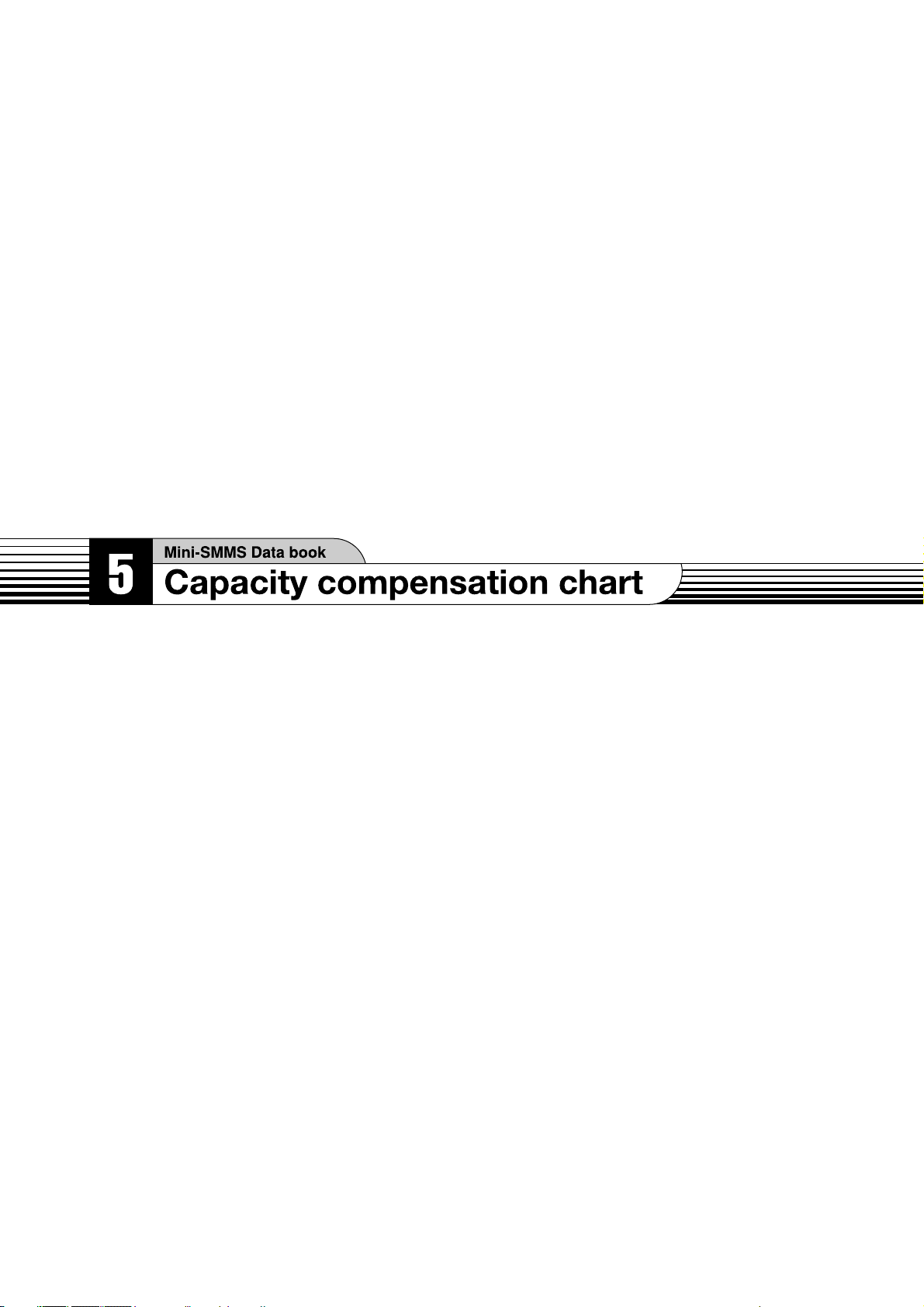
5-1. Cooling/heating capacity characteristics
1
Cooling capacity calculation method :
Required cooling capacity = Cooling capacity x Factor ( , , , , *1) kW
Indoor air wet bulb temperature vs. capacity correction value
1.2
1.1
(Example)
Design Indoor conditions : 22
Capacity correction value : 1.09
1.2
o
C WB
048
5
1.0
0.9
0.8
Capacity correction value
15
20 24
Capacity correction value
Indoor air wet bulb temp. (oC)
Outdoor air dry bulb temperature vs.capacity correction value
1.2
1.1
1
0.9
-
50 51015202530354043
Capacity correction value
Outdoor air dry bulb temp. (oC)
1.1
1.0
0.9
0.8
15
20 24
Indoor air wet bulb temp. (oC)
(Example)
Design Outdoor conditions : 17
Capacity correction value : 1.14
1.2
1.1
1
0.9
-
50 51015202530354043
Capacity correction value
Outdoor air dry bulb temp. (oC)
o
C DB
1 : Coefficient to use for correction of outdoor unit capacity when total capacity of the indoor
*
units are not equal to the outdoor unit capacity.
5
-1
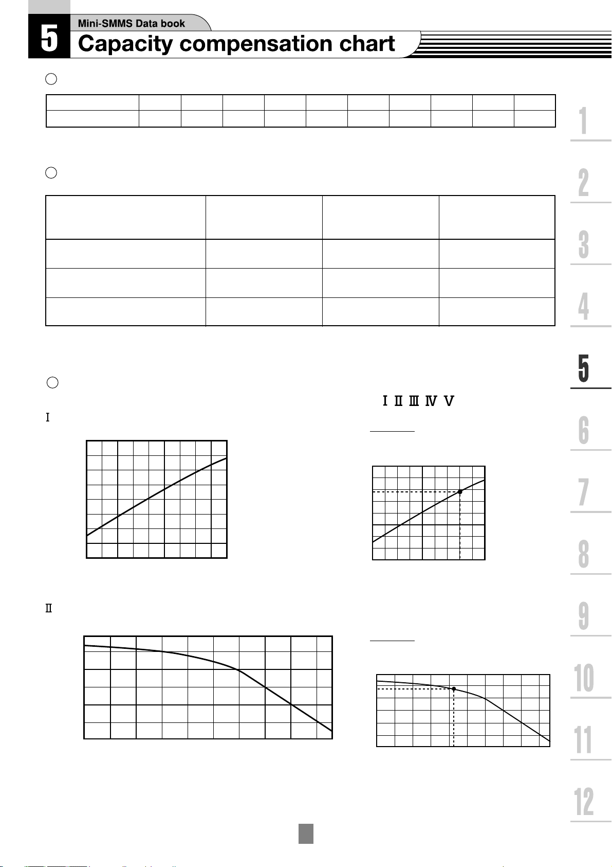
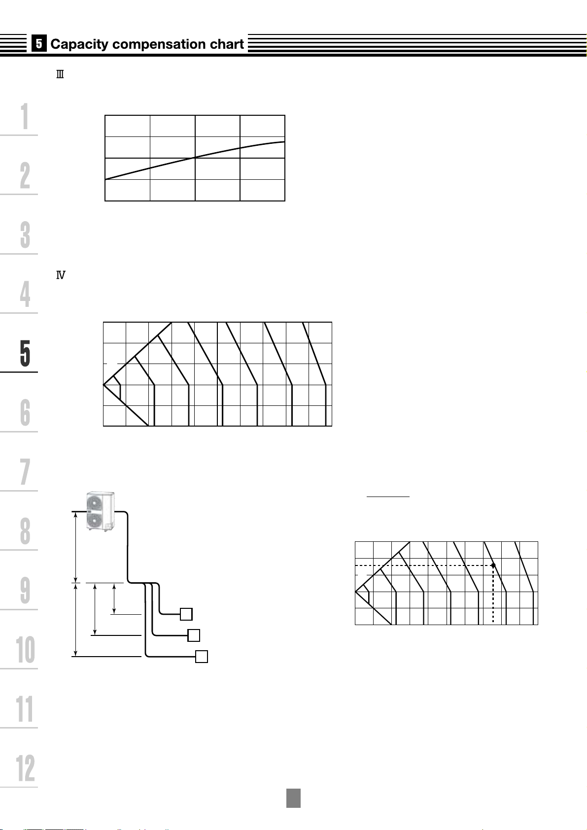
Air flow variation ratio of indoor unit vs. capacity correction (For concealed duct type only)
30
20
10
0
-
10
-
20
010203040
Pipe length (Equivalent length) L(m)
Hight of outdoor unit H (m)
50 60 70 80 90 100
100%
98
96
94
92
90
88
86
84
82
1.1
1.0
0.9
80 90 100 110 120
Capacity correction value
Connecting pipe length and lift difference between indoor and outdoor units vs. capacity correction value
Air flow variation ratio (%)
30
20
10
0
-
10
Hight of outdoor unit H (m)
-
20
100%
010203040
Outdoor unit
L is the longest one of
(Ll + a, Ll + b, Ll + c)
ho Ll
H = ho +
(Largest one of ha, hb, and hc)
94
96
98
92
90
50 60 70 80 90 100
88
86
84
82
Pipe length (Equivalent length) L(m)
(Example)
Design Pipelength : 55m
Height of outdoor unit : 15m
Capacity correction value: 89%
ha
hb
hc
a
A
b
B
Indoor unit
c
C
5
-2
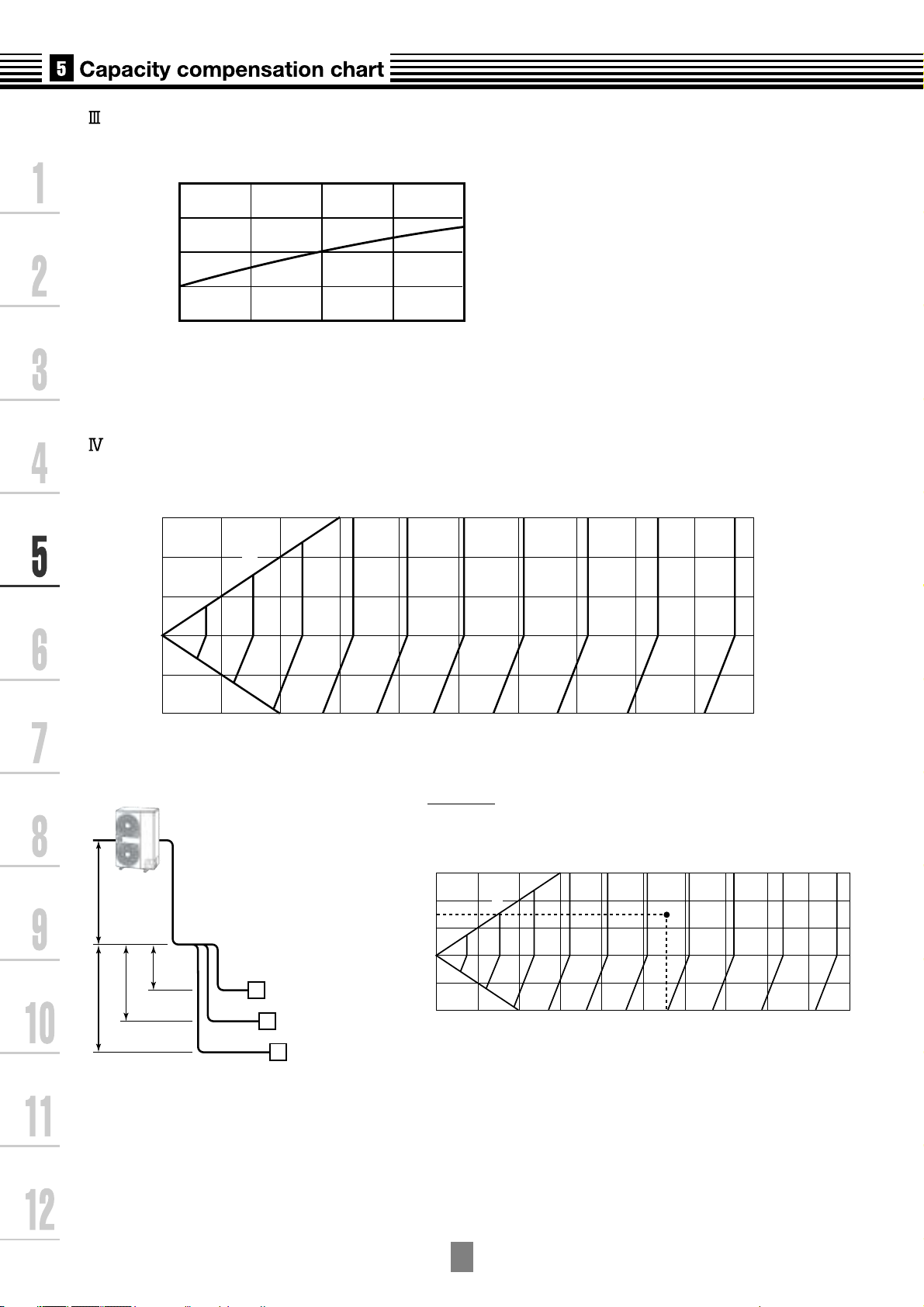
Correction of outdoor unit diversity
1.1
1
(Example)
Design Outdoor unit : 5.0HP
Indoor units total capacity : 5.5HP
(Capacity ratio : 110%)
Capacity correction value : 1.03%
0.9
0.8
0.7
Capacity correction value
80 80 100 110 120 130
1.1
1
0.9
0.8
0.7
Capacity correction value
80 80 100 110 120 130
Standard capacity ratio
Indoor units total capacity ratio (%)
2
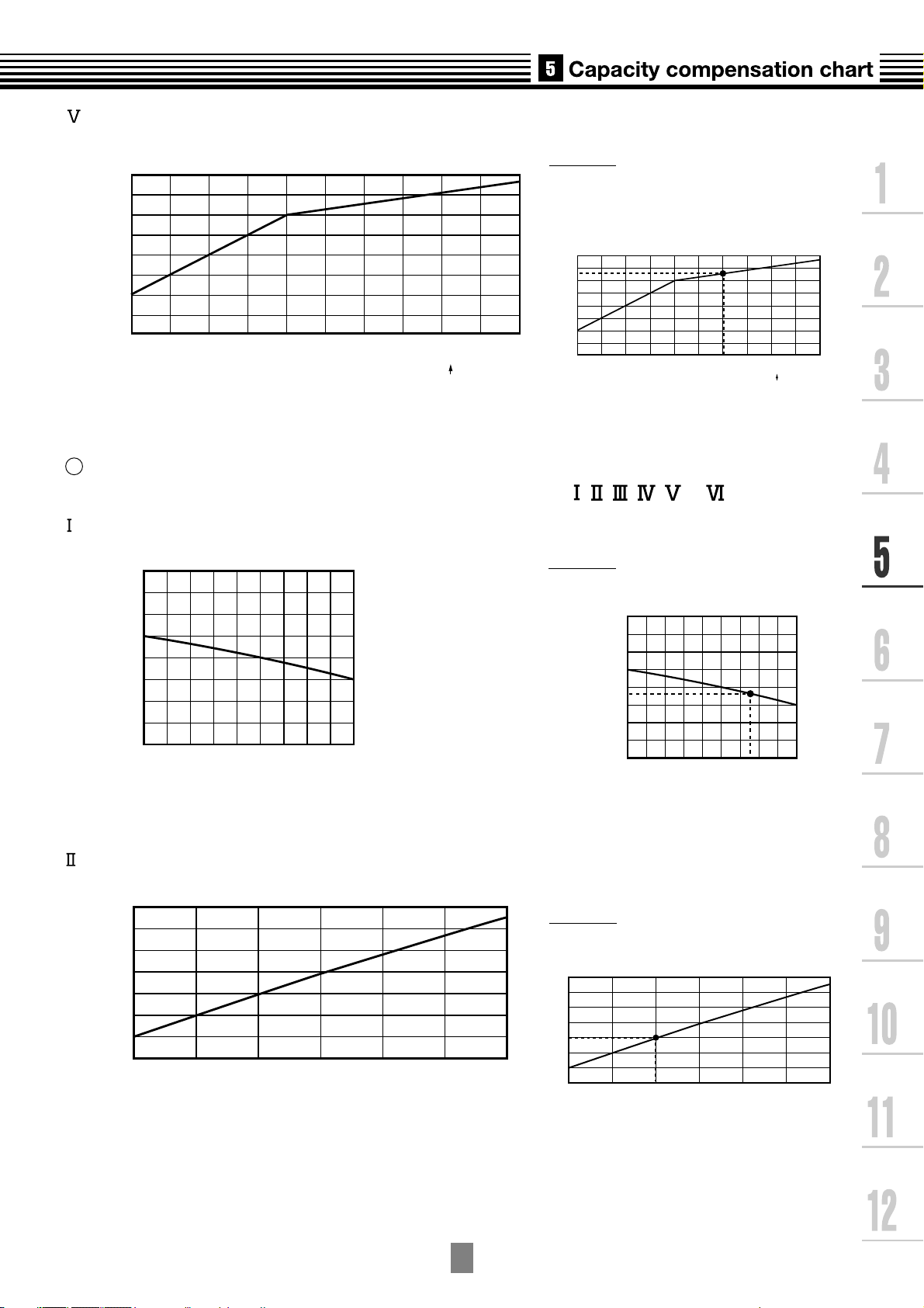
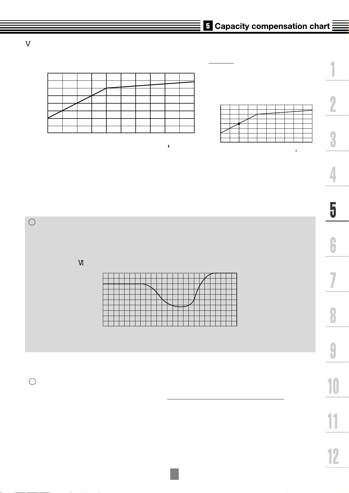
Heating capacity calculation method :
Indoor units total capacity ratio (%)
Required heating capacity = Heating capacity x Factor ( , , , , *1, *2) kW
Indoor air dry bulb temperature vs. capacity correction value
1.2
1.1
1.0
0.9
0.8
15 20 24
Capacity correction value
Indoor air dry bulb temp. (oC)
(Example)
Design Indoor conditions : 21.5
Capacity correction value : 0.98
1.2
1.1
1.0
0.9
0.8
15 20 24
Capacity correction value
Indoor air dry bulb temp. (oC)
Standard capacity ratio
o
C DB
Outdoor air wet bulb temperature vs. capacity correction value
1.2
1.1
1
0.9
0.8
0.7
0.6
0.5
Capacity correction value
-
15
-
10
-
50 51015
Outdoor air wet bulb temp. (oC)
1 : Coefficient to use for correction of outdoor unit capacity when total capacity of the indoor
*
(Example)
Design Outdoor conditions :
-
5oC WB
Capacity correction value : 0.8
1.2
1.1
1
0.9
0.8
0.7
0.6
0.5
Capacity correction value
-
15
-
10
-
50 51015
Outdoor air wet bulb temp. (oC)
units are not equal to the outdoor unit capacity.
2 : Refer to item 3.
*
5
-3
Air flow variation ratio of indoor unit vs. capacity correction (For concealed duct type only)
Pipe length (Equivalent length) L (m)
Height of outdoor unit H (m)
30
99
98
97
96
95
94
20
10
0
-
10
-
20
0 10 20304050607080 90100
100%
1.1
1.0
0.9
80 90 100 110 120
Capacity correction value
Air flow variation ratio (%)
Connecting pipe length and lift difference between indoor and outdoor units vs. capacity correction value
30
20
10
100%
0
-
10
-
20
0 102030 405060708090100
Height of outdoor unit H (m)
98
99
97
96
95
Pipe length (Equivalent length) L (m)
Outdoor unit
L is the longest one of
(Ll + a, Ll + b, Ll + c)
ho Ll
H = ho +
(Largest one of ha, hb, and hc)
ha
hb
hc
a
A
b
B
Indoor unit
c
C
94
(Example)
Design Pipe length : 75m
Heigh of outdoor unit : 15m
Capacity correction value : 95.1%
5
-4
Correction of outdoor unit diversity
1.1
1
(Example)
Design Outdoor unit : 5HP
Indoor units total capacity : 4.5HP
(Capacity ratio : 90%)
Capacity correction value : 0.9%
0.9
0.8
0.7
Capacity correction value
80 90 100 110 120 130
Standard capacity ratio
Indoor units total capacity ratio (%)
1 : Coefficient to use for correction of outdoor unit capacity when total capacity of the indoor
*
1.1
1
0.9
0.8
0.7
Capacity correction value
80 90 100 110 120 130
Indoor units total capacity ratio (%)
Standard capacity ratio
units are not equal to the outdoor unit capacity.
3
Capacity correction in case of frost on the outdoor heat exchanger in heating
Correct the heating capacity when frost was found on the outdoor heat exchanger.
Heating capacity = Capacity after correction of outdoor unit × Correction value of capacity resulted from frost
(Capacity after correction of outdoor unit : Heating capacity calculated in the above item 2.)
Capacity correction in case of frost on the outdoor heat exchanger
1.0
0.9
0.8
Capacity correction value
-
15
Capacity calculation for each indoor unit
4
-
10
Outdoor air wet bulb temp. (oC)
-
50 510
Capacity for each indoor unit
= Capacity after correction of outdoor unit x
Required standard capacity of indoor unit
Total value of standard indoor unit capacity
5
-5
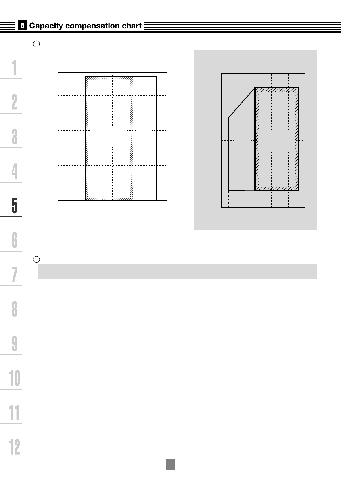
5
Operating temperature range
In cooling time
45
40
C)
35
o
30
25
20
15
10
5
0
Outdoor air dry bulb temp. (
-
5
-
10
Continuously
operable
range
(in pull down)
Usable range
3025 28201510
C)
o
-
-
Outdoor air wet bulb temp. (
-
-
In heating time
20
15
10
5
Continuously
0
5
Usable range
(in warming-up)
10
15
20
5 1015202530
operable
range
Indoor air wet bulb temp. (oC)
Indoor air dry bulb temp. (oC)
Rated conditions
6
Cooling :
Indoor air temperature 27oC DB/19.0oC WB, Outdoor air temperature 35oC DB
Heating :
Indoor air temperature 20oC DB, Outdoor air temperature 7oC DB/6oC WB
5
-6
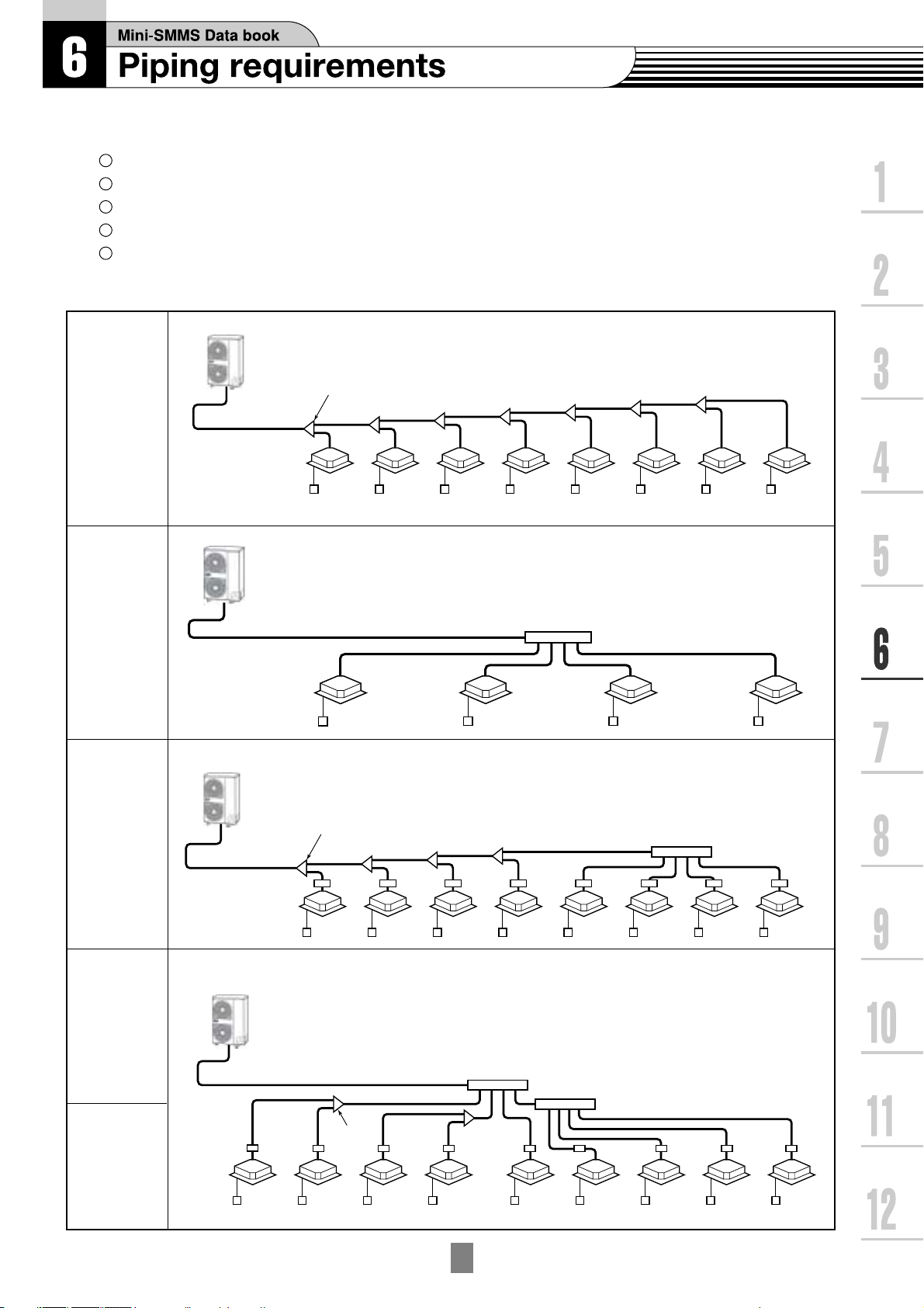
6-1. Free branching system
1
Line branching system
2
Header branching system
3
Header branching system after line branching
4
Line branching system after header branching
5
Header branching system after header branching
The above five branching systems are available to dramatically increase the flexibility of refrigerant piping design.
Outdoor unit
Line
branching
system
Indoor unit
Branching joint
controller
Outdoor unit
Remote
Header
branching
system
Header
branching
system
after line
branching
Line
branching
system after
header
branching
Indoor unit
* In case of "PMV Kit"
Outdoor unit
PMV
Kit
Indoor unit
* In case of "PMV Kit"
Outdoor unit
Remote controller
Branching joint
Remote
controller
Branching header
Branching header
Branching header
Header
branching
system after
header
branching
Indoor
unit
PMV
Kit
Remote
controller
Branching
joint
6
-1
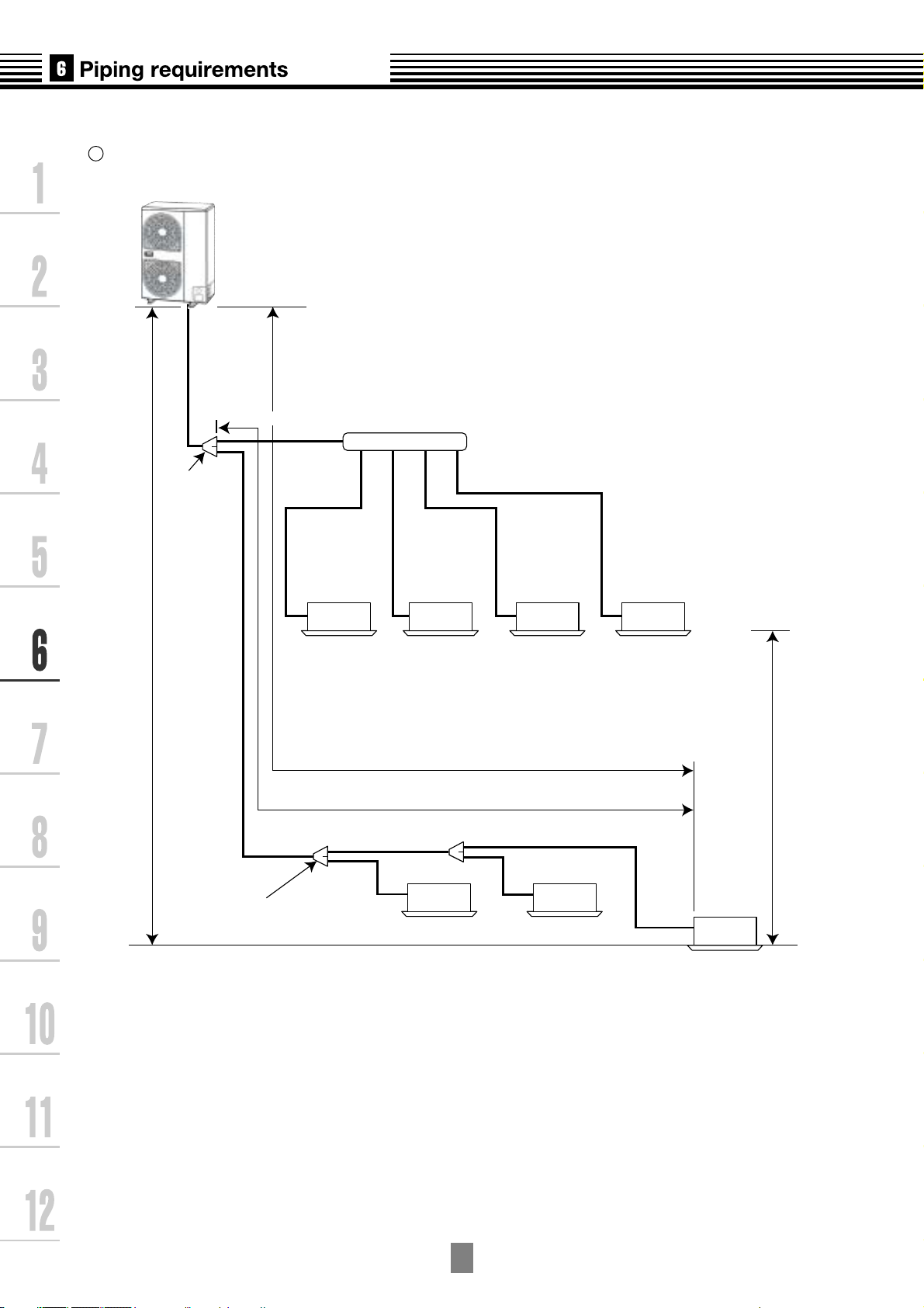
6-2. Refrigerant piping length and piping size
1
Allowable length and height difference of refrigerant piping
Outdoor unit
Main
pipe
L1
Branching pipe
L2
Branching header
1st branching
section
Branching
pipe
L3
Height
difference
between
Indoor and
outdoor unit
H1
ab cd
Indoor unit
Equivalent length corresponded to farthest piping
Equivalent length corresponded to farthest piping after 1st branching Li
L4
ef
Y-shape
branching joint
Height difference
between indoor units
H2
L
g
A
6
-2

1
Allowable length and height difference of refrigerant piping
Allowable value Piping section
Piping
Length
Total extension of pipe
(Liquid pipe, real length)
Furthest piping length L
(*1)
Max.equivalent length of
main pipe
Equivalent length of furthest
piping from 1st branching
Li (*1)
Max.real length of indoor
unit connecting pipe
Real length
Equivalent
length
180m
100m
125m
65m
35m
15m
L1+L2+L3+L4+
a+b+c+d+e+f+g
L1+L3+L4+g
L1
L3+L4+g
a, b, c, d, e, f, g
Upper outdoor
unit
Height between indoor and
outdoor units H1
Height
Difference
Height between indoor units H2
*1 Furthest indoor unit from 1st branch to be named "A"
Lower outdoor
unit
30m
20m
15m
_
_
_
6
-3

2
Selection of refrigerant piping
Outdoor unit
Gas pipe
Main
pipe
Liquid pipe
1st branching
section
1
4
Branching
Branching
2
pipe
2
pipe
3
Y-shape
Branching joint
4
Branching header
4
3
Indoor unit
2
3
3 3
4
3 3
Indoor unit
6
-4

2
Selection of refrigerant piping (cont.)
No. Piping parts Name Selection of pipe size
Size of main pipe
Outdoor unit
1
1st branching
section
Branching
section
2
Branching
section
Branching
section
3
Indoor unit
Main pipe
Pipe size between branching sections
Total capacity codes of indoor units at down stream side
Branching
pipe
Note) If the total capacity code value of indoor units exceeds that of the
outdoor units, apply the capacity code of outdoor units.
Connecting pipe size of indoor unit
Indoor unit
connecting
pipe
Outdoor unit capacity type
0401 type
0501 type
0601 type
Equivalent to HP
Below 2.8
2.8 to below 6.4
6.4 to below 7.2
Indoor unit capacity type
007, 009, 012 type
015, 018 type
024, 030, 036, 048 type
Gas pipe (mm)
Gas pipe
Gas pipe (mm)
15.9
15.9
19.1
(mm)
12.7
15.9
19.1
9.5
12.7
15.9
Liquid pipe (mm)
9.5
9.5
9.5
Liquid pipe
(mm)
9.5
9.5
9.5
Liquid pipe (mm)
6.4
6.4
9.5
Selection of branching section
Y-shape
Y-shape branching joint
Branching
header
Note) *1 : When using a Y-shape branching joint for the 1st branch, select
according to capacity code of the outdoor unit.
*2 : For 1 line after branching header indoor units with a maximum
capacity code of 6.0 in total can be connected.
For 4 branches
For 8 branches
4
branching joint
Branching
section
Branching
header
Minimum wall thickness for R410A application
Soft
OK
OK
Harf Hard
or Hard
OK
OK
OD
(inch)
1/4"
3/8"
OD
(mm)
6.35
9.52
Total capacity codes of indoor units at down stream side
Minimum wall
thickness (mm)
0.80
0.80
Equivalent to HP
Below 6.4
6.4 to below 7.8
Below 7.8
Below 7.8
Model name
RBM-BY53E
RBM-BY103E
RBM-HY1043E
RBM-HY1083E
OK
OK
NG*
OK
OK
OK
1/2"
5/8"
3/4"
12.70
15.88
19.05
6
0.80
1.00
1.00
-5
*If the pipe size is
use a suitable material.
O
19.0 or more,
/

6-3. Refrigerant piping length and piping size with PMV Kit
1
Allowable length and height difference of refrigerant piping
Outdoor unit
Main
pipe
L1
Branching pipe
L2
Branching header
1st branching
section
Branching
pipe
L3
Height
difference
between
Indoor and
outdoor unit
H1
a
bcd
hi jk
Indoor unit
Equivalent length corresponded to farthest piping
Equivalent length corresponded to farthest piping after 1st branching
L4
Y-shape
Branching joint
e
lm
f
PMV Kit
Height difference
between indoor units
(PMV Kit)
L
Li
g
n
H2
A
6
-6

1
Allowable length and height difference of refrigerant piping
Allowable value Piping section
Piping
Length
Total extension of pipe
(Liquid pipe, real length)
Furthest piping length L
(*1)
Equivalent length of furthest
piping from 1st branching Li
(*1)
Real length
Equivalent
length
150m
65m
80m
50mMax.equivalent length of main pipe
15m
15mMax.real length of indoor unit connecting pipe
L1+L2+L3+L4+
a+b+c+d+e+f+g+
h+i+j+k+l+m+n
L1+L3+L4+g+n
L1
L3+L4+g+n
a+h, b+i, c+j, d+k,
e+l, f+m, g+n
Real length between PMV Kit and indoor unit
Upper outdoor
unit
Height between indoor and
outdoor unit H1
Height
Difference
Lower outdoor
unit
Height between indoor units (PMV Kit) H2
Height difference between highest indoor unit or PMV Kit and
lowest indoor unit or PMV Kit shall be 15m or less
*1 Furthest indoor unit from 1st branch to be named "A"
Not Available Available
PMV
Kit
Indoor unit Indoor unit
2m or more
and up to 10m
30m
20m
15m
PMV
Kit
h, i, j, k, l, m, n
_
_
_
NOTE
Don,t connect two or more indoor units to one PMV Kit. Arrange one indoor unit and one PMV Kit set to 1 by 1.
6
-7

2
Selection of refrigerant piping
Outdoor unit
Gas pipe
Main
pipe
Liquid pipe
1st branching
section
1
4
Branching
pipe
2
Branching
pipe
2
Branching header
4
5 5
3
Y-shape
Branching joint
4
3
3
Indoor unit
2
5
5 5
3 3
4
3 3
PMV Kit
5 5
6
Indoor unit
-8

2
Selection of refrigerant piping (cont.)
No. Piping parts Name Selection of pipe size
Size of main pipe
Outdoor unit
1
1st branching
section
Branching
section
2
Branching
section
Branching
section
3
Indoor unit
Main pipe
Pipe size between branching sections
Total capacity codes of indoor units at down stream side
Branching
pipe
Note) If the total capacity code value of indoor units exceeds that of the
outdoor units, apply the capacity code of outdoor units.
Connecting pipe size of indoor unit
Indoor unit
connecting
pipe
Outdoor unit capacity type
0401 type
0501 type
0601 type
Equivalent to HP
Below 2.8
2.8 to below 6.4
6.4 to below 7.2
Indoor unit capacity type
007, 009, 012 type
015, 018 type
024 type
Gas pipe (mm)
Gas pipe
Gas pipe (mm)
15.9
15.9
19.1
(mm)
12.7
15.9
19.1
9.5
12.7
15.9
Liquid pipe (mm)
9.5
9.5
9.5
Liquid pipe
(mm)
9.5
9.5
9.5
Liquid pipe (mm)
6.4
6.4
9.5
Selection of branching section
Branching
4
section
5
PMV Kit PMV Kit
Y-shape
branching joint
Branching
header
Y-shape branching joint
Branching
header
Note) *1 : When using a Y-shape branching joint for the 1st branch, select
according to capacity code of the outdoor unit.
*2 : For 1 line after branching header indoor units with a maximum
capacity code of 6.0 in total can be connected.
Selection of PMV Kit
*1
For 4 branches
*2
For 8 branches
Indoor unit capacity type
007, 009, 012 type
015, 018, 024 type
Minimum wall thickness for R410A application
Soft
OK
Harf Hard
or Hard
OK
OD
(inch)
1/4"
OD
(mm)
6.35
Total capacity codes of indoor units at down stream side
Minimum wall
thickness (mm)
0.80
Equivalent to HP
Below 6.4
6.4 to below 7.8
Below 7.8
Below 7.8
Model name
RBM-BY53E
RBM-BY103E
RBM-HY1043E
RBM-HY1083E
Model name
RBM-PMV0361E
PBM-PMV0901E
OK
OK
OK
NG*
OK
OK
OK
OK
3/8"
1/2"
5/8"
3/4"
9.52
12.70
15.88
19.05
6
0.80
0.80
1.00
1.00
-9
*If the pipe size is
use a suitable material
as detailed in the installation manual.
O
19.0 or more,
/

6-4. Refrigerant piping example
1
In case of without "PMV Kit"
Outdoor unit
MCY-MAP0601HT
Main
=60m
L1
pipe
(7.6)
1st branching
L3
1
=20m
section
Branching pipe
Branching pipe
(3.4)
=7m
L2
=1m
a
(0.8) (1.0) (0.8) (0.8)
MMU-AP0071MH
(4.2)
2
Branching header
Capacity
code
=6m
b
MMU-AP0091H MMU-AP0701MH MMU-AP0701MH
Indoor unit
f
=4m
e
(1.7)
=10m
=8m
c
d
=15m
10m
12m
Y-shape
Branching joint
(2.5)
3
MMU-AP0151H
6
MMU-AP0241H
-10

Piping size
Mark
L1
L2
L3
a
b
c
Equivalent length
(m)
60
7
20
1
6
8
Seclection method
(capacity code)
0.8 + 1.0 + 0.8 + 0.8 = 3.4
1.7 + 2.5 = 4.2
0.8
1.0
0.8
Gas pipe
(mm)
O
19.1
/
O
15.9
/
O
15.9
/
O
9.5
/
O
9.5
/
O
9.5
/
Liquid pipe
(mm)
O
9.5
/
O
9.5
/
O
9.5
/
O
6.4
/
O
6.4
/
O
6.4
/
d
e
f
Y-shape branching joint and Header
Mark
1
2
1st branching
Branch header
15
4
10
0.8
1.7
2.5
Y-joint or Header select
(capacity code)
6
(capacity code of outdoor unit)
0.8 +1.0 +0.8 +0.8 = 3.4
(a+b+c+d=L2)
O
9.5
/
O
12.7
/
O
15.9
/
Model name
RBM-BY53E
RBM-HY1043E
O
/
O
/
O
/
6.4
6.4
9.5
3
Y-shape branch joint
1.7 + 2.5 = 4.2
(e+f=L3)
6
-11
RBM-BY53E

2
In cace of PMV Kit
Outdoor unit
MCY-MAP0601HT
Main
=20m
L1
pipe
(7.6)
1st branching
L3
1
=6m
section
Branching pipe
Branching pipe
(3.4)
=3m
L2
=4m
a
(0.8) (1.0) (0.8) (0.8)
MMU-AP0071MH
(4.2)
2
Branching header
Capacity
code
=3m
b
MMU-AP0091H MMU-AP0701MH MMU-AP0701MH
Indoor unit
f
=4m
e
(1.7)
=6m
=6m
c
=7m
d
10m
12m
Y-shape
Branching joint
(2.5)
3
MMU-AP0151H
6
-12
PMV Kit
MMU-AP0241H

Piping size
Mark
L1
L2
L3
a
b
c
d
e
f
Equivalent length
(m)
20
3
6
4
3
6
7
4
6
Seclection method
(capacity code)
0.8 + 1.0 + 0.8 + 0.8 = 3.4
1.7 + 2.5 = 4.2
0.8
1.0
0.8
0.8
1.7
2.5
Gas pipe
(mm)
O
19.1
/
O
15.9
/
O
15.9
/
O
9.5
/
O
9.5
/
O
9.5
/
O
9.5
/
O
12.7
/
O
15.9
/
Liquid pipe
(mm)
O
9.5
/
O
9.5
/
O
9.5
/
O
6.4
/
O
6.4
/
O
6.4
/
O
6.4
/
O
6.4
/
O
9.5
/
Y-shape branching joint and Header
Mark
1
2
3
PMV Kit
1st branching
Branch header
Y-shape branch joint
Mark
Y-joint or Header select
(capacity code)
6
(capacity code of outdoor unit)
0.8 +1.0 +0.8 +0.8 = 3.4
(a+b+c+d=L2)
1.7 + 2.5 = 4.2
(e+f=L3)
PMV Kit select
(capacity code)
0.8
1.0
0.8
Model name
RBM-BY53E
RBM-HY1043E
RBM-BY53E
Model name
RBM-PMV0361E
RBM-PMV0361E
RBM-PMV0361E
6
0.8
1.7
2.5
-13
RBM-PMV0361E
RBM-PMV0901E
RBM-PMV0901E

6-5. Charging requirement with additional refrigerant
After the system has been vacuumed,replace the vacuum pump
with a refrigerant cylinder and charge the system
with additional refrigerant.
R410A
Calculating the amount of additional refrigerant required
(Calculation)
Additional refrigerant charge amount is calculated from size of liquid pipe at site and its real length.
Additional refrigerant
charge amount at site
Table 1
Pipe dia. at liquid side
Additional refrigerant amount/1m (kg)
Table 2
Outdoor unit capacity type
Compensation by outdoor HP (kg)
Example :
(0501 type)
L1
b
R (kg)
L1
O
9.5 : 10m
/
O
6.4 : 3m
/
Real length of
=
liquid pipe
ab c d
L2
c
0401 type
L2
O
9.5 : 10m
/
O
6.4 : 4m
/
Additional refrigerant charge
amount per liquid pipe 1m
X
(Table 1)
O
6.4
/
0.025
-
0.8
L3
O
0.055
0501 type
-
L3
d
9.5
/
0.4
O
/
O
/
9.5 : 5m
6.4 : 5m
+
0601 type
0
a
Compensation by
outdoor HP
(Table 2)
O
9.5 : 3m
/
Additional charge amount R (kg) = (Lx X 0.025kg/m) + (Ly X 0.055kg/m) + (
= (12 X 0.025kg) + (28 X 0.055kg) + (
=1.44kg
Lx : Real total length of liquid pipe
Ly : Real total length of liquid pipe
Note)
If the additional refrigerant amount indicates a negative result from the calculation,
use air conditioner without the adding of any additional refrigerant.
6
-14
-
0.4kg)
O
6.4 (m)
/
O
9.5 (m)
/
-
0.4kg)


7-1. Outdoor unit
Strainer
Sensor
PMV
Strainer
Sensor (TL)
Sensor (TO)
Heat exchanger
(TE)
Check joint
Liquid tank
Capillary
tube 2
High-pressure
sensor
Strainer
Solenoid valve
(SV5)
Check valve
Check joint
High pressure
switch
Sensor (TD)
Muffler
4-Way valve
Solenoid valve
(SV2)
Solenoid valve
(SV4)
Sensor (TS)
Capillary
tube 1
Low-pressure
sensor
Check joint
Accumulator
Liquid side
packed valve
Gas side
ball valve
Compressor (Inverter)
7
-1

7-2. Explanation of Functional Parts
y
)
p
r
r
)
r
Functional part name Functional outline Connector
Solenoid valve SV2 1) Low pressure release function CN312(Whight)
2) High pressure release function
3) Gas balance function during off time
4) Hot gas bypass into accumulator
SV4 1) High pressure release function CN311(Blue)
2) Low pressure release function
SV5 1) Preventive function for high-pressure rising CN310(Whight)
in heating operation
Capillary tube 1 ID:Ø1.5 Length:200mm
2 ID:Ø2.2 Length:100mm
4-Wa
valve 1) Cooling/heating exchange CN317(Blue)
2) Reverse defrost
PMV 1) Super heat control function in all heating and majority CN300(Whight)
(Pulse motor valve) heating operation
2) Sub-cool adjustment function in cooling operation
Temp. sensor TD 1) Protection of compressor discharge temp. Used for release CN502(Whight)
TS 1) Controls super heat in heating operation CN504(Whight)
TE 1) Controls defrost in heating operation CN505(Green)
2) Controls outdoor fan in heating operation
TL 1) Detects under cool in cooling operation CN521(Whight)
TO 1) Detects outside temperature CN507(Yellow)
High-ressure sensor 1) Detects high pressure and controls compressor capacity CN501(Red)
2) Detects high pressure in cooling operation, and controls
the fan in low ambientcooling operation
Low-pressure sensor 1) Detects low pressure in cooling operation and controls CN500(Whight)
compressor capacity
2
Detects low pressure in heating operation, and controls
the su
Compressor case heate
Accumulator case heater 1) Prevents liquid accumulation to accumulato
1) Prevents liquid accumulation to compresso
er heat
CN316(Whight
CN321(Red)
7
-2

7-3. Indoor Unit
Liquid side
Pulse Motor
Valve (PMV)
Gas side
Strainer
Sensor
(TC2)
Capillary tube
Strainer
Sensor
(TCJ)
Air heat exchanger
at indoor side
Fan
Sensor
(TA)
M
Fan motor
(NOTE) MMU-AP0071YH to AP0121YH type air conditioners do not have a TC2 sensor .
Sensor
(TC1)
Functional part name Functional outline
Pulse Motor Valve
Temp. sensor
PMV
1. TA
2. TC1
3. TC2
4. TCJ
(Connector CN082 (6P): Blue)
1)Controls super heat in cooling operation
2)Controls under cool in heating operation
3)Recovers refrigerant oil in cooling operation
4)Recovers refrigerant oil in heating operation
(Connector CN104 (2P): Yellow)
1)Detects indoor suction temperatur e
(Connector CN100 (3P): Brown)
1)Controls PMV super heat in cooling operation
(Connector CN101 (2P): Black)
1)Controls PMV under cool in heating operation
(Connector CN102 (2P): Red)
1)Controls PMV super heat in cooling operation
MMU-AP0071 to AP0121YH only
2)
Controls PMV under cool in heating operation
7
-3


CAUTIONS
f
f
f
f
(
f
f
f
(1) Keep the refrigerant piping system and the indoor-indoor/indoor-outdoor control wiring systems together.
(2) When running power supplies and control wires parallel to each other, run them through separate conduits or
maintain a suitable distance between them.
(Current capacity of power supplies: 10A or less for 300m, 50A or less for 500m)
8-1. General
orm wiring of the power supplies in conformance with the regulation of
Per
the local electrical company.
Use a 2 core shield wire
and connecting o
indoor units to outdoor units.
or control wiring on connecting indoor units,
This is recommended to prevent possible noise issues.
Be sure to connect an earth leakage breaker to the power supply o
the indoor units.
Never connect 220-240V power to the control wiring terminal block
U1,U2,U3,U4). Fault will be caused.
Locate wiring system
or the control and refrigerant piping system
in the same line.
Arrange the cables so that the electrical wires do not come in to contact
with high-temperature parts of the pipework ; otherwise insulation will melt
and an accident may be caused.
Do not turn on the power supply o
the indoor units until vacuuming o
the refrigerant pipe has finished.
8-2. Connection of power supply
The details are as follows.
(Terminal block) (Stripping length power cable)
NL
LN
10
10
50
Power cable
(Cord clamp)
(Protective bush : Accessory)
90
Earth line
Power cable
Power supply specifications
Select the power supply cabling and fuse of each outdoor unit from the following
specifications:
3 core cable in conformance with Design 60245 IEC 66
Do not connect the units looping via the terminal blocks (L,N)
8
-1

8-3. Electrical wiring desin8-3. Electrical wiring desin
8-3. Electrical wiring desin
8-3. Electrical wiring desin8-3. Electrical wiring desin
2QYG TUWRRN[
Outdoor
power source
Indoor
power source
/%; /#2*6UGTKGU 0` *\8 8
/%;/#2*6&UGTKGU 0`*\ 8
Earth leakage Breaker
hand switch
Over current breaker
(fuse) switch
Single phase
50Hz 220-240V
or 60Hz 220V
Earth leakage breaker
power switch
'CTVJ
.0
1XGTEWTTGPV
DTGCMGTHWUGUYKVEJ
'CTVJNGCMCIGDTGCMGT
1WVFQQTWPKV RQYGTUWRRN
Pull box
Indoor unitIndoor unitIndoor unit
[
Indoor unitIndoor unitIndoor unit
Determine the wire size for the indoor unit according to the number of
conncted indoor units downstream.
Outdoor Unit capacities and power supply wire sizes (Reference)
Observe local regulations in reference to the wire size selection and installtion.
Outdoor unit capacity type Field fuse
0401 type 6
0501 type 6
0601 type 6
* Design 60245 IEC66
Wire size *
2
Max. 22 m 32A
mm
2
Max. 19 m 32A
mm
2
Max. 17 m 40A
mm
For Indoor Unit power supply
(Must be independent from the outdoor unit power supply )
Item
Model
All models of indoor units
NOTE:
The above connecting lengths stated in the table indicate the length from the isolator to the outdoor unit. When the
power supply of the indoor units are connected in parallel, it is assumed that no more than a 2% voltage drop will occur.
If the connecting length is to exceed the stated lengths, select a suitable wire in accordance with the local wiring standards.
2.0mm2 MAX.20m 3.5mm2 MAX.50m
Power supply wiring
Field fuseWire size
15A
88
-2-2
8
-2
-2-2
88
(Revised edition in 7.Apr.2006)

8-4. Design of control wiring
Power supply
Single phase
220-240V 50Hz
220Hz 60Hz
[Central remote controller] (Option)
TCB-SC642TLE2 (For line 64)
(Open)
Earth
Communication wire for control
between outdoor unit and
indoor unit
Connection of shield wire must be connected
(Connected to all connecting sections in each indoor unit)
Communication wire for
control between indoor
and PMV Kit
Remote
controller
Control device
U1U3U2
U4
Outdoor unit
Indoor unit
U1 U2
U1 U2
U3 U4
A B
Outdoor
unit
B
U1 U2
U1 U2
U3 U4
A B
(Header)
Outdoor
unit
U1 U2
A B
(Follower)
PMV Kit (option)
Communication wire for
control between indoor
and PMV Kit (option)
Mini-SMMS system
A
Outdoor
unit
U3 U4
U1 U2
B
U1 U2
A B
U1 U2
A B
U1 U2
A B
B
U1 U2
A B
U1 U2
A B
Remote
controller
Wire specification, quantity, size of crossover wiring and remote controller wiring
Name Q’ty
Crossover wiring (A + B)
(indoor-indoor / indoor-outdoor / control wiring,
central control wiring) *Total Control wiring length
Remote controller wiring
Control wiring between indoor and PMV Kit
Remote controller
2 cores
2 cores
Remote controller
Size
Up to 500m Up to 1000m 1000 to 2000m
2
1.25mm
0.5 to 2.0mm
2
Be sure to use the attached cable. MIN 2m - MAX 10m
---
2.0mm
2
Specification
Shield wire
(1) The crossover wiring and central control wiring uses a 2-core non-polarity communication wire. Use 2-core shielded wire to prevent
possible noise issues. Connect the end of the shielded wires and earth(ground) at both the outdoor and indoor unit.
Where the shielded wire is connected between a central controller and a outdoor unit, only earth(ground) at one end of
the central control line.
(2) Use 2-core non-polarity wire for remote controller. (A, B terminals)
Use 2-core non-polarity wire for wiring of group control. (A, B terminals)
8
-3

8-5. Example of system wiring Design
n
1
In cace of without "PMV Kit"
Outdoo r pow er supply Outdo or un it
MCY-MAP###1HT ser ies : 1N~ 50Hz 220V-240V
MCY-MAP###1HT2D series : 1N~ 60Hz 220V
Centr al remot e co ntro ller pow er supply
1N~ 50Hz 220-240V
1N~ 60Hz 220V
Indoor unit
Remote contr oller
Central r emote contr oller (o ption)
Over cur rent b reaker (f use) sw itch
Earth leaka ge breaker
Main sw itch
Pull bo x
PMV Kit (opt ion)
[Outdo or un it]
LN
(Option)
Earth
U1 U2
U3 U4
(Open)
(Open)
To other
refrigerant system
L N U1 U2 U3 U4
Earth
Relay connector (At shipment from factory : No connection)
Connection of shield wire must be connected
(Connected to all connecting sections in each Indoor u
Control wiring between indoor units
[Indoo r unit ]
Indoor unit
power supply
1N~ 50Hz 220-240V
1N~ 60Hz 220V
U1 U2 A B U1 U2 A B U1 U2 A B U1U2 A B
Eart h
control
ad
LN
Eart h
LN LN LN
AB AB AB
Earth Earth
Remote cont roll er
[Grou p cont rol]
8
-4

2
n
In cace of "PMV Kit"
[Outdo or un it]
Outdoo r pow er supply Outdo or un it
MCY-MAP###1HT ser ies : 1N~ 50Hz 220V-240V
MCY-MAP###1HT2D series : 1N~ 60Hz 220V
Central remot e co ntro lle r power supply
1N~ 50Hz 220-240V
1N~ 60Hz 220V
(Option)
LN
Earth
U1 U2
U3 U4
(Open)
(Open)
To other
refrigerant system
L N U1 U2 U3 U4
Earth
Relay connector (At shipment from factory : No connection)
Indoor unit
Remote contr oller
Central r emote contr oller (o ption)
Over cur rent b reaker (f use) sw itch
Earth leaka ge breaker
Main sw itch
Pull bo x
PMV Kit (opt i on)
[Indoo r unit ]
PMV Kit (option)
Indoor unit
power supply
1N~ 50Hz 220-240V
1N~ 60Hz 220V
Connection of shield wire must be connected
(Connected to all connecting sections in each Indoor u
Control wiring between indoor units
U1 U2 A B U1 U2 A B U1 U2 A B U1U2 A B
Indoor control
Indoor control
PC boad
PC boad
CN82
Eart
h
LN
AB AB AB
Eart h
LN LN LN
Earth Earth
Remote cont roll er
[Grou p cont rol]
8
-5

8-6. Electrical characteristics
Outdoor units
Model name
MCY-MAP0401HT
MCY-MAP0501HT
MCY-MAP0601HT
Legend
RLA : Rated Load Amps
FLA : Full Load Amps
kW : Fan Motor Rated Output (kW)
NOTE : RLA is based on the following conditions.
Indoor temperature : 27
Outdoor temperature : 35
Nominal
(V-Ph-Hz)
230-1-50
230-1-50
230-1-50
Voltage Range Compressor
Min Max RLA kW FLA MCA MOCP ICF
198
198
198
o
CDB / 19oCWB
o
CDB
264
264
264
Indoor units
Type Model
4-way Air
Discharge
Cassette Type
Compact
4-way Cassette
(600 x 600) Type
2-way Air
Discharge
Cassette Type
1-way Air
Discharge
Cassette Type
MMU-AP 0091 H
MMU-AP 0121 H
MMU-AP 0151 H
MMU-AP 0181 H
MMU-AP 0241 H
MMU-AP 0271 H
MMU-AP 0301 H
MMU-AP 0361 H
MMU-AP 0481 H
MMU-AP 0071 MH
MMU-AP 0091 MH
MMU-AP 0121 MH
MMU-AP 0151 MH
MMU-AP 0181 MH
MMU-AP 0071 WH
MMU-AP 0091 WH
MMU-AP 0121 WH
MMU-AP 0151 WH
MMU-AP 0181 WH
MMU-AP 0241 WH
MMU-AP 0271 WH
MMU-AP 0301 WH
MMU-AP 0071 YH
MMU-AP 0091 YH
MMU-AP 0121 YH
MMU-AP 0152 SH
MMU-AP 0182 SH
MMU-AP 0242 SH
Nominal Voltage
(V-Ph-Hz)
230-1-50
230-1-50
230-1-50
230-1-50
230-1-50
230-1-50
230-1-50
230-1-50
230-1-50
230-1-50
230-1-50
230-1-50
230-1-50
230-1-50
230-1-50
230-1-50
230-1-50
230-1-50
220-1-50
230-1-50
230-1-50
230-1-50
230-1-50
230-1-50
230-1-50
230-1-50
230-1-50
230-1-50
50Hz
Fan Motor Power Supply
22.4
25.3
27.8
MCA : Minimum Circuit Amps
MOCP : Maximum Overcurrent Protection (Amps)
ICF : Maximum Instantaneous Current Flow Start
0.063 x 2
0.063 x 2
0.063 x 2
1.2
1.3
1.3
25
28
31
32
32
40
50Hz
Voltage Range
Min Max
198
198
198
198
198
198
198
198
198
198
198
198
198
198
198
198
198
198
198
198
198
198
198
198
198
198
198
198
264
264
264
264
264
264
264
264
264
264
264
264
264
264
264
264
264
264
264
264
264
264
264
264
264
264
264
264
Fan Motor
kW FLA
0.060
0.060
0.060
0.060
0.060
0.060
0.060
0.090
0.090
0.060
0.060
0.060
0.060
0.060
0.053
0.053
0.053
0.039
0.039
0.053
0.053
0.053
0.022
0.022
0.022
0.030
0.030
0.030
0.20
0.20
0.22
0.24
0.28
0.28
0.40
0.68
0.93
0.32
0.35
0.36
0.48
0.48
0.36
0.36
0.36
0.37
0.37
0.53
0.53
0.54
0.28
0.28
0.28
0.40
0.42
0.71
Power Supply
MCA MOCP
0.25
0.25
0.28
0.30
0.35
0.35
0.50
0.85
1.16
0.40
0.44
0.45
0.60
0.60
0.45
0.45
0.45
0.46
0.46
0.66
0.66
0.68
0.35
0.35
0.35
0.49
0.53
0.88
-
-
-
15
15
15
15
15
15
15
15
15
15
15
15
15
15
15
15
15
15
15
15
15
15
15
15
15
15
15
15
8
-6

Indoor units
Type Model
Concealed Duct
Type
Slim Duct Type
Concealed Duct
High Static
Pressure Type
Under Ceiling Type
High Wall 1series
Type
High Wall 2series
Type
Floor Standing
Cabinet Type
Floor Standing
Concealed Type
Floor Standing
Type
MMD-AP 0071 BH
MMD-AP 0091 BH
MMD-AP 0121 BH
MMD-AP 0151 BH
MMD-AP 0181 BH
MMD-AP 0241 BH
MMD-AP 0271 BH
MMD-AP 0301 BH
MMD-AP 0361 BH
MMD-AP 0481 BH
MMD-AP 0071 SPH
MMD-AP 0091 SPH
MMD-AP 0121 SPH
MMD-AP 0151 SPH
MMD-AP 0181 SPH
MMD-AP 0181 H
MMD-AP 0241 H
MMD-AP 0271 H
MMD-AP 0361 H
MMD-AP 0481 H
MMC-AP 0151 H
MMC-AP 0181 H
MMC-AP 0241 H
MMC-AP 0271 H
MMC-AP 0361 H
MMC-AP 0481 H
MMK-AP 0071 H
MMK-AP 0091 H
MMK-AP 0121 H
MMK-AP 0151 H
MMK-AP 0181 H
MMK-AP 0241 H
MMK-AP 0072 H
MMK-AP 0092 H
MMK-AP 0122 H
MML-AP 0071 H
MML-AP 0091 H
MML-AP 0121 H
MML-AP 0151 H
MML-AP 0181 H
MML-AP 0241 H
MML-AP 0071 BH
MML-AP 0091 BH
MML-AP 0121 BH
MML-AP 0151 BH
MML-AP 0181 BH
MML-AP 0241 BH
MMF-AP 0151 H
MMF-AP 0181 H
MMF-AP 0241 H
MMF-AP 0271 H
MMF-AP 0361 H
MMF-AP 0481 H
Nominal Voltage
(V-Ph-Hz)
230-1-50
230-1-50
230-1-50
230-1-50
230-1-50
230-1-50
230-1-50
230-1-50
230-1-50
230-1-50
230-1-50
230-1-50
230-1-50
230-1-50
230-1-50
230-1-50
230-1-50
230-1-50
230-1-50
230-1-50
230-1-50
220-1-50
230-1-50
230-1-50
230-1-50
230-1-50
230-1-50
230-1-50
230-1-50
230-1-50
230-1-50
230-1-50
230-1-50
230-1-50
230-1-50
230-1-50
230-1-50
230-1-50
230-1-50
230-1-50
230-1-50
230-1-50
230-1-50
230-1-50
230-1-50
230-1-50
230-1-50
230-1-50
230-1-50
230-1-50
230-1-50
230-1-50
230-1-50
Voltage Range
Min Max
198
198
198
198
198
198
198
198
198
198
198
198
198
198
198
198
198
198
198
198
198
198
198
198
198
198
198
198
198
198
198
198
198
198
198
198
198
198
198
198
198
198
198
198
198
198
198
198
198
198
198
198
198
264
264
264
264
264
264
264
264
264
264
264
264
264
264
264
264
264
264
264
264
264
264
264
264
264
264
264
264
264
264
264
264
264
264
264
264
264
264
264
264
264
264
264
264
264
264
264
264
264
264
264
264
264
Fan Motor
kW FLA
0.120
0.120
0.120
0.120
0.120
0.120
0.120
0.120
0.120
0.120
0.060
0.060
0.060
0.060
0.060
0.160
0.160
0.160
0.260
0.260
0.030
0.030
0.040
0.040
0.080
0.080
0.030
0.030
0.030
0.030
0.030
0.030
0.030
0.030
0.030
0.045
0.045
0.045
0.045
0.070
0.070
0.019
0.019
0.019
0.070
0.070
0.070
0.037
0.037
0.063
0.063
0.110
0.160
0.33
0.33
0.39
0.39
0.50
0.60
0.60
0.70
0.96
1.13
0.35
0.35
0.37
0.38
0.47
0.93
1.55
1.55
1.87
2.12
0.33
0.37
0.48
0.48
0.90
0.96
0.35
0.35
0.35
0.37
0.37
0.40
0.20
0.21
0.22
0.30
0.30
0.49
0.49
0.54
0.54
0.29
0.29
0.29
0.52
0.52
0.53
0.77
0.77
1.01
1.01
1.48
1.84
50Hz
Power Supply
MCA MOCP
0.41
0.41
0.49
0.49
0.62
0.75
0.75
0.88
1.20
1.41
0.44
0.44
0.47
0.48
0.59
1.16
1.94
1.94
2.34
2.65
0.41
0.46
0.60
0.60
1.13
1.20
0.44
0.44
0.44
0.46
0.46
0.50
0.24
0.26
0.27
0.37
0.37
0.62
0.62
0.68
0.68
0.36
0.36
0.36
0.65
0.65
0.66
0.96
0.96
1.27
1.27
1.85
2.30
15
15
15
15
15
15
15
15
15
15
15
15
15
15
15
15
15
15
15
15
15
15
15
15
15
15
15
15
15
15
15
15
15
15
15
15
15
15
15
15
15
15
15
15
15
15
15
15
15
15
15
15
15
8
-7

8-6. Electrical characteristics
Outdoor units
Model name
MCY-MAP0401HT2D
MCY-MAP0501HT2D
MCY-MAP0601HT2D
Legend
RLA : Rated Load Amps
FLA : Full Load Amps
kW : Fan Motor Rated Output (kW)
NOTE : RLA is based on the following conditions.
Indoor temperature : 27
Outdoor temperature : 35
Nominal
(V-Ph-Hz)
220-1-60
220-1-60
220-1-60
Voltage Range Compressor
Min Max RLA kW FLA MCA MOCP ICF
198
198
198
o
CDB / 19oCWB
o
CDB
242
242
242
Indoor units
Type Model
4-way Air
Discharge
Cassette Type
Compact
4-way Cassette
(600 x 600) Type
2-way Air
Discharge
Cassette Type
1-way Air
Discharge
Cassette Type
MMU-AP 0091 H
MMU-AP 0121 H
MMU-AP 0151 H
MMU-AP 0181 H
MMU-AP 0241 H
MMU-AP 0271 H
MMU-AP 0301 H
MMU-AP 0361 H
MMU-AP 0481 H
MMU-AP 0071 MH
MMU-AP 0091 MH
MMU-AP 0121 MH
MMU-AP 0151 MH
MMU-AP 0181 MH
MMU-AP 0071 WH
MMU-AP 0091 WH
MMU-AP 0121 WH
MMU-AP 0151 WH
MMU-AP 0181 WH
MMU-AP 0241 WH
MMU-AP 0271 WH
MMU-AP 0301 WH
MMU-AP 0071 YH
MMU-AP 0091 YH
MMU-AP 0121 YH
MMU-AP 0152 SH
MMU-AP 0182 SH
MMU-AP 0242 SH
Nominal Voltage
(V-Ph-Hz)
220-1-60
220-1-60
220-1-60
220-1-60
220-1-60
220-1-60
220-1-60
220-1-60
220-1-60
220-1-60
220-1-60
220-1-60
220-1-60
220-1-60
220-1-60
220-1-60
220-1-60
220-1-60
220-1-60
220-1-60
220-1-60
220-1-60
220-1-60
220-1-60
220-1-60
220-1-60
220-1-60
220-1-60
60Hz
Fan Motor Power Supply
22.4
25.3
27.8
MCA : Minimum Circuit Amps
MOCP : Maximum Overcurrent Protection (Amps)
ICF : Maximum Instantaneous Current Flow Start
0.063 x 2
0.063 x 2
0.063 x 2
1.2
1.3
1.3
25
28
31
32
32
40
60Hz
Voltage Range
Min Max
198
198
198
198
198
198
198
198
198
198
198
198
198
198
198
198
198
198
198
198
198
198
198
198
198
198
198
198
242
242
242
242
242
242
242
242
242
242
242
242
242
242
242
242
242
242
242
242
242
242
242
242
242
242
242
242
Fan Motor
kW FLA
0.060
0.060
0.060
0.060
0.060
0.060
0.060
0.090
0.090
0.060
0.060
0.060
0.060
0.060
0.053
0.053
0.053
0.039
0.039
0.053
0.053
0.053
0.022
0.022
0.022
0.030
0.030
0.030
0.21
0.21
0.23
0.25
0.29
0.29
0.42
0.70
0.98
0.31
0.33
0.35
0.47
0.47
0.38
0.38
0.38
0.44
0.44
0.61
0.61
0.67
0.30
0.30
0.30
0.40
0.45
0.75
Power Supply
MCA MOCP
0.26
0.26
0.29
0.31
0.37
0.37
0.52
0.88
1.22
0.39
0.41
0.44
0.59
0.59
0.47
0.47
0.47
0.55
0.55
0.76
0.76
0.84
0.37
0.37
0.37
0.50
0.57
0.94
-
-
-
15
15
15
15
15
15
15
15
15
15
15
15
15
15
15
15
15
15
15
15
15
15
15
15
15
15
15
15
8
-8

Indoor units
Type Model
Concealed Duct
Type
Slim Duct Type
Concealed Duct
High Static
Pressure Type
Under Ceiling Type
High Wall 1series
Type
High Wall 2series
Type
Floor Standing
Cabinet Type
Floor Standing
Concealed Type
Floor Standing
Type
MMD-AP 0071 BH
MMD-AP 0091 BH
MMD-AP 0121 BH
MMD-AP 0151 BH
MMD-AP 0181 BH
MMD-AP 0241 BH
MMD-AP 0271 BH
MMD-AP 0301 BH
MMD-AP 0361 BH
MMD-AP 0481 BH
MMD-AP 0071 SPH
MMD-AP 0091 SPH
MMD-AP 0121 SPH
MMD-AP 0151 SPH
MMD-AP 0181 SPH
MMD-AP 0181 H
MMD-AP 0241 H
MMD-AP 0271 H
MMD-AP 0361 H
MMD-AP 0481 H
MMC-AP 0151 H
MMC-AP 0181 H
MMC-AP 0241 H
MMC-AP 0271 H
MMC-AP 0361 H
MMC-AP 0481 H
MMK-AP 0071 H
MMK-AP 0091 H
MMK-AP 0121 H
MMK-AP 0151 H
MMK-AP 0181 H
MMK-AP 0241 H
MMK-AP 0072 H
MMK-AP 0092 H
MMK-AP 0122 H
MML-AP 0071 H
MML-AP 0091 H
MML-AP 0121 H
MML-AP 0151 H
MML-AP 0181 H
MML-AP 0241 H
MML-AP 0071 BH
MML-AP 0091 BH
MML-AP 0121 BH
MML-AP 0151 BH
MML-AP 0181 BH
MML-AP 0241 BH
MMF-AP 0151 H
MMF-AP 0181 H
MMF-AP 0241 H
MMF-AP 0271 H
MMF-AP 0361 H
MMF-AP 0481 H
Nominal Voltage
(V-Ph-Hz)
220-1-60
220-1-60
220-1-60
220-1-60
220-1-60
220-1-60
220-1-60
220-1-60
220-1-60
220-1-60
220-1-60
220-1-60
220-1-60
220-1-60
220-1-60
220-1-60
220-1-60
220-1-60
220-1-60
220-1-60
220-1-60
220-1-60
220-1-60
220-1-60
220-1-60
220-1-60
220-1-60
220-1-60
220-1-60
220-1-60
220-1-60
220-1-60
220-1-60
220-1-60
220-1-60
220-1-60
220-1-60
220-1-60
220-1-60
220-1-60
220-1-60
220-1-60
220-1-60
220-1-60
220-1-60
220-1-60
220-1-60
220-1-60
220-1-60
220-1-60
220-1-60
220-1-60
220-1-60
Voltage Range
Min Max
198
198
198
198
198
198
198
198
198
198
198
198
198
198
198
198
198
198
198
198
198
198
198
198
198
198
198
198
198
198
198
198
198
198
198
198
198
198
198
198
198
198
198
198
198
198
198
198
198
198
198
198
198
242
242
242
242
242
242
242
242
242
242
242
242
242
242
242
242
242
242
242
242
242
242
242
242
242
242
242
242
242
242
242
242
242
242
242
242
242
242
242
242
242
242
242
242
242
242
242
242
242
242
242
242
242
Fan Motor
kW FLA
0.120
0.120
0.120
0.120
0.120
0.120
0.120
0.120
0.120
0.120
0.060
0.060
0.060
0.060
0.060
0.160
0.160
0.160
0.260
0.260
0.030
0.030
0.040
0.040
0.080
0.080
0.030
0.030
0.030
0.030
0.030
0.030
0.030
0.030
0.030
0.045
0.045
0.045
0.045
0.070
0.070
0.019
0.019
0.019
0.070
0.070
0.070
0.037
0.037
0.063
0.063
0.110
0.160
0.35
0.35
0.41
0.41
0.52
0.63
0.63
0.73
1.00
1.18
0.32
0.32
0.36
0.37
0.44
1.06
2.07
2.07
2.38
2.60
0.35
0.39
0.50
0.50
0.94
1.00
0.37
0.37
0.37
0.39
0.39
0.40
0.21
0.22
0.23
0.29
0.29
0.51
0.51
0.61
0.61
0.31
0.31
0.31
0.53
0.53
0.59
0.77
0.77
1.04
1.04
1.58
2.01
60Hz
Power Supply
MCA MOCP
0.43
0.43
0.51
0.51
0.65
0.78
0.78
0.91
1.25
1.48
0.41
0.41
0.45
0.47
0.56
1.32
2.59
2.59
2.98
3.25
0.43
0.48
0.63
0.63
1.18
1.25
0.46
0.46
0.46
0.48
0.48
0.50
0.26
0.27
0.29
0.36
0.36
0.63
0.63
0.76
0.76
0.39
0.39
0.39
0.66
0.66
0.73
0.96
0.96
1.29
1.29
1.97
2.52
15
15
15
15
15
15
15
15
15
15
15
15
15
15
15
15
15
15
15
15
15
15
15
15
15
15
15
15
15
15
15
15
15
15
15
15
15
15
15
15
15
15
15
15
15
15
15
15
15
15
15
15
15
8
-9


9-1-1. Specifications
Specifications (50Hz)
50Hz
Model name MMU-
Cooling/Heating capacity (Note 1)
Power supply
Electrical
characteristics
Appearance
Outer
dimension
Running current
Power consumption
Starting current (A)
Main unit
Ceiling
panel
Main unit
Ceiling
panel
(kW)
(A)
(kW)
Model
Panel color
Height (mm)
Width (mm)
Depth (mm)
Height (mm)
Width (mm)
Depth (mm)
AP0091H
2.8/3.2
AP0121H
3.6/4.0
1 phase 50Hz 230V (220-240V) (Separate power supply for indoor units is required.)
0.17
0.020
0.30
AP0151H
4.5/5.0
0.19
0.022
0.33
Heat-insulating material attached Zinc hot dipping steel plate
AP0181H
5.6/6.3
0.026
Moon white (Munsell/2.5GY 9.0/0.5)
AP0241H
7.1/8.0
0.21
0.36
RBC-U21PG (W)-E
256 319
840
840
35
950
950
AP0271H
0.24
0.032
0.42
8.0/9.0
AP0301H
9.0/10.0
0.35
0.048
0.59
AP0361H
11.2/12.5
0.59
0.070
0.87
AP0481H
14.0/16.0
0.81
0.110
1.23
Total weigh
Heat exchanger
Soundproof/Heat-insulating
material
Fan unit
Air filter
Controller
Connecting
pipe
Sound pressure level (Note 2)
(High/Mid/Low)
PMV Kit Not available
Main unit (kg)
Ceiling panel (kg)
Fan
Standard air flow
(High/Mid/Low)
Motor (W)
Gas side (mm)
Liquid side (mm)
Drain port (Nominal dia. mm)
(m3/h)
(dB(A))
20 22 23 28
4.5
Finned tube
Non-flammable insulation
Turbo fan
800
(730/680)
O
9.5 O/12.7 O/15.9
/
30/29/27 31/29/27 32/29/28 34/31/28 37/33/30 40/36/33 44/38/34
(830/790)
O
6.4
/
930
1,050
(920/800)
60 90
Standard filter (Long life filter)
Remote controller
25 (Polyvinyl chloride tube)
1,200
(920/820)
1,320
(1,110/850)
O
9.5
/
1,680
(1,300/1,070)
2,040
(1,430/1,130)
Note 1 : The cooling capacities and electrical characteristics are measured under the conditions specified by JIS B 8615 based on the
Note 2 : The sound level are measured in an anechoic chamber in accordance with JIS B8616. Normally, the values measured in the
Note : Rated conditions Cooling : Indoor air temperature 27oC DB/19oC WB, Outdoor air temperature 35oC DB
reference piping. The reference piping consists of 5 m of main piping and 2.5 m of branch piping connected with 0 meter height.
actual operating environment become larger than the indicated values due to the effects of external sound.
Heating : Indoor air temperature 20
o
C DB, Outdoor air temperature 7oC DB/6oC WB
9-1
-1

Specifications (60Hz)
60Hz
Model name MMU-
Cooling/Heating capacity (Note 1)
Power supply
Electrical
characteristics
Appearance
Outer
dimension
Running current
Power consumption
Starting current
Main unit
Ceiling
panel
Main unit
Ceiling
panel
Model
Panel color
Height
Width
Depth
Height
Width
Depth
(kW)
(A)
(kW)
(A)
(mm)
(mm)
(mm)
(mm)
(mm)
(mm)
AP0091H
2.8/3.2
AP0121H
3.6/4.0
0.18 0.20 0.22 0.26 0.37 0.61 0.85
0.020 0.022 0.026 0.032 0.048 0.070 0.110
0.30 0.33 0.36 0.42 0.59 0.87 1.23
AP0151H
4.5/5.0
1 phase 60Hz 220V (Separate power supply for indoor units is required.)
Heat-insulating material attached Zinc hot dipping steel plate
AP0181H
5.6/6.3
Moon white (Munsell/2.5GY 9.0/0.5)
256 319
AP0241H
7.1/8.0
RBC-U21PG (W) -E
840
840
35
950
950
AP0271H
8.0/9.0
AP0301H
9.0/10.0
AP0361H
11.2/12.5 14.0/16.0
AP0481H
Total weight
Heat exchanger
Soundproof/Heat-insulating
material
Fan unit
Air filter
Controller
Connecting
pipe
Sound pressure level (Note 2)
(High/Mid./Low)
PMV Kit Not available
Main unit
Ceiling panel
Fan
Standard air flow
(High/Mid./Low)
Motor
Gas side
Liquid side
Drain port
(Nominal dia. mm)
(kg)
(kg)
3
(m
(W)
(mm)
(mm)
(dB(A))
20
/h)
800
(730/680)
O
9.5
/
30/29/27
O
6.4
/
(830/790)
22 23
4.5
Finned tube
Non-flammable insulation
Turbo fan
930
31/29/27 32/29/28 34/31/28 37/33/30 40/36/33 44/38/34
1,050
(920/800)
60
Standard filter (Long life filter)
Remote controller
O
12.7
/
25 (Polyvinyl chloride tube)
(920/820)
1,200
1,320
(1,110/850)
O
15.9
/
O
9.5
/
28
1,680
(1,300/1,070)
90
2,040
(1,430/1,130)
Note 1 : The cooling capacities and electrical characteristics are measured under the conditions specified by JIS B 8615 based on the
reference piping. The reference piping consists of 5 m of main piping and 2.5 m of branch piping connected with 0 meter height.
Note 2 : The sound levels are measured in an anechoic chamber in accordance with JIS B8616. Normally, the values measured in
Note : Rated conditions Cooling : Indoor air temperature 27
the actual operating environment become larger than the indicated values due to the effects of external sound.
Heating : Indoor air temperature 20
O
C DB/19OC WB, Outdoor air temperature 35OC DB
O
C DB, Outdoor air temperature 7OC DB/6OC WB
9-1
-2

9-1-2. Dimension
MMU-AP0091H to P0481H
Suction grille (Air suction port)
Electric parts box
415
950
254.5
Z
35o
723 hanging bolt pitch
950
381.6
panel external dimension
Hanging bolt
M10 or W3/8 local arrange
840
480
227
B
35
97
Bottom face of ceiling Bottom face of ceiling
57.5
25
188
Bottom face
of ceiling
Knockout for flesh air intake
For
O
100
/
64
57
Z view
346.5
790 hanging bolt pitch
panel external dimension
ceiling open dimension
For branch duct knockout square hole
(2 positions at right side)
Drain discharge port
A
210
88
360
Stand-up
640 or less
Indoor unit Bottom face of ceiling
(NOTE)
As ABS is used for the drain discharge
port of the main unit, the vinyl chloride
paste cannot be used.
Use the flexible hose (Band fix)
included in the package.
130
Stand-up
850 or less
Drain-up standing-up size Space required for installation and servicing
Air discharge port (4-way)
860 to 910
840
250 70
270
105
105
30
1000 or more
15 or more
1000 or more
860 to 910
ceiling open dimension
Refrigerant pipe
connecting port
(Gas)
Refrigerant pipe
connecting port
(Liquid)
45
113
Model A B
AP0091H to AP0301H
AP0361H to AP0481H
1000 or more
15 or more
O
/
174
150
256
319
mm
120
183
Wired remote controller
RBC-AMT31E
4
2.7
Simple wired remote controller
RBC-AS21E2
Wireless remote controller kit
120
TCB-AX21U(W)-E2
Weekly timer application
120
RBC-AMT31E and RBC-EXW21E2
16
Check port
( 450)
9-1
200
Check port
( 450)
-3
200
Note: All dimensions are in mm.

9-1-3. Wiring diagram
Model:MMU-AP0091H, AP0121H, AP0151H, AP0181H, AP0241H,
MMU-AP0271H, AP0301H, AP0361H, AP0481H, AP0561H
PMV
LM1
LM2
TA
TC1
TCJ
TC2
1
2
1
2
1
2
1
2
33
1
2
1
2
1
2
(BLK)
CN101
1
CN34
(RED)
FS
(YEL)
(RED)
CN104
3 1
321
1 2 3 4 5
1 2 3 4 5
CN33
(WHI)
1 2 3 4 5
1 2 3 4 5
1 2 3 4 5
1 2 3 4 5
CN102
2
(BRN)
CN100
1
PNL
2
CN80
(GRN)
3
MCC-1402
1 2 3 4 5
1 2 3 4 5
CN82
(BLU)
1 2 3 4 5 6
6 4 3 1 2 5
1 2 3 4 5
6 4 3 1 2 5
(WHI)
CN333
Indoor control P.C. board
Fuse
DC20V
Power
250V~
T3.15A
DC15V
DC12V
DC7V
circuit
supply
EXCT
1
CN73
2
(RED)
Filter input
1
2
CN70
(WHI)
CN20
(BLU)
(YEL)
CN309
CN41
(BLU)
CN40
(BLU)
CN81
(BLK)
CN60
(WHI)
1 2 3 4 5
1 2 3
1 2 3
1 2
1 2 3 4 5
3 4 5 6
1 2
1 2 3
1 2 3
1 2
(Option)
BLK
BLK
BLU
BLU
MCC-1401
CN03
adaptor
P.C. board
2 2
1 1
CN02
WHI
1 2
(BLU)
(RED)
1 2
2
U
1
U
Outdoor unit
X Y
BLK WHI BLK
WHI
CN001
(WHI)
CN1
(WHI)
1 2
1 2
remote controller
Adaptor for wireless
1 2
1 2
controller
Wired remote
TR
Network adaptor
(Option)
Network
1 2
1 2
3 3
CN01
(WHI)
BLK
BA
2
U
1
U
FM
1 2 3 4 5
1 2 3 4 5 6
(BLU)
CN334
5 4 3 2 1
5 4 3 2 1
CN68
(BLU)
RY302
123
123
DM
circuit
Motor drive
RY303
123
(GRY)
CN304
Fuse
T6.3A
+
~
250V~
123
1
RED
2
CN67
(BLK)
3
Ð
~
WHI
P301
BLK
121
CN66
screw
unit earth
Flow selector
(WHI)
CN61
CN32
CN50
CN44
WHI
RED
(YEL)
1 2 3 4 51 2 3
T10
1 2
(WHI)
4 5 6
(WHI)
2
(BLN)
Closed end
connector
S(N)R(L)
Indoor unit
(Fandrive)
Power supply
Earth screw
Single phase
220V 60Hz
220-240V 50Hz
BLK : BLACK
GRY : GRAY
PNK : PINK
ORN : ORANGE
GRN : GREEN
Parts name
Color identification
RED : RED
WHI : WHITE
YEL : YELLOW
BLU : BLUE
Fan motor
BRN : BROWN
FM
Symbol
1. indicates the terminal block, the letter inside
Indoor temp sensor
Temp sensor
Temp sensor
Temp sensor
Lover motor
TA
TC1
TCJ
TC2
LM1, LM2
indicates the control P.C. board.
indicates the terminal number.
2. A dotted line and broken line indicate the wiring on site.
3.
Drain pump motor
Float switch
Drain control relay
Pulse Motor Valve
FS
DM
PMV
RY302
9-1
-4

9-1-4. Sensible capacity table
(MMU-AP***H)
Cooling capacity
TC : Total Capacity (kW) SHC : Sensible Heat Capacity (kW)
Outdoor
air temp.
size 23°CDB 26°CDB 27°CDB 28°CDB 30°CDB 32°CDB
009 23.0 2.5 2.0 2.7 2.1 2.8 2.1 2.9 2.1 3.1 2.1 3.2 2.0
012 23.0 3.3 2.4 3.5 2.5 3.6 2.5 3.7 2.5 3.9 2.5 4.1 2.4
015 23.0 4.1 3.0 4.4 3.2 4.5 3.2 4.6 3.2 4.9 3.2 5.1 3.1
°CDB
10.0 2.5 2.0 2.7 2.1 2.8 2.1 2.9 2.1 3.1 2.1 3.2 2.0
12.0 2.5 2.0 2.7 2.1 2.8 2.1 2.9 2.1 3.1 2.1 3.2 2.0
14.0 2.5 2.0 2.7 2.1 2.8 2.1 2.9 2.1 3.1 2.1 3.2 2.0
16.0 2.5 2.0 2.7 2.1 2.8 2.1 2.9 2.1 3.1 2.1 3.2 2.0
18.0 2.5 2.0 2.7 2.1 2.8 2.1 2.9 2.1 3.1 2.1 3.2 2.0
20.0 2.5 2.0 2.7 2.1 2.8 2.1 2.9 2.1 3.1 2.1 3.2 2.0
21.0 2.5 2.0 2.7 2.1 2.8 2.1 2.9 2.1 3.1 2.1 3.2 2.0
25.0 2.5 2.0 2.7 2.1 2.8 2.1 2.9 2.1 3.1 2.1 3.2 2.0
27.0 2.5 2.0 2.7 2.1 2.8 2.1 2.9 2.1 3.1 2.1 3.2 2.0
29.0 2.5 2.0 2.7 2.1 2.8 2.1 2.9 2.1 3.1 2.1 3.2 2.0
31.0 2.5 2.0 2.7 2.1 2.8 2.1 2.9 2.1 3.1 2.1 3.2 2.0
33.0 2.5 2.0 2.7 2.1 2.8 2.1 2.9 2.1 3.1 2.1 3.2 2.0
35.0 2.5 2.0 2.7 2.1 2.8 2.1 2.9 2.1 3.1 2.1 3.2 2.0
37.0 2.5 1.9 2.7 2.1 2.7 2.1 2.8 2.1 3.0 2.0 3.1 2.0
39.0 2.4 1.9 2.6 2.0 2.7 2.0 2.8 2.0 2.9 2.0 3.1 1.9
10.0 3.3 2.4 3.5 2.5 3.6 2.5 3.7 2.5 3.9 2.5 4.1 2.4
12.0 3.3 2.4 3.5 2.5 3.6 2.5 3.7 2.5 3.9 2.5 4.1 2.4
14.0 3.3 2.4 3.5 2.5 3.6 2.5 3.7 2.5 3.9 2.5 4.1 2.4
16.0 3.3 2.4 3.5 2.5 3.6 2.5 3.7 2.5 3.9 2.5 4.1 2.4
18.0 3.3 2.4 3.5 2.5 3.6 2.5 3.7 2.5 3.9 2.5 4.1 2.4
20.0 3.3 2.4 3.5 2.5 3.6 2.5 3.7 2.5 3.9 2.5 4.1 2.4
21.0 3.3 2.4 3.5 2.5 3.6 2.5 3.7 2.5 3.9 2.5 4.1 2.4
25.0 3.3 2.4 3.5 2.5 3.6 2.5 3.7 2.5 3.9 2.5 4.1 2.4
27.0 3.3 2.4 3.5 2.5 3.6 2.5 3.7 2.5 3.9 2.5 4.1 2.4
29.0 3.3 2.4 3.5 2.5 3.6 2.5 3.7 2.5 3.9 2.5 4.1 2.4
31.0 3.3 2.4 3.5 2.5 3.6 2.5 3.7 2.5 3.9 2.5 4.1 2.4
33.0 3.3 2.4 3.5 2.5 3.6 2.5 3.7 2.5 3.9 2.5 4.1 2.4
35.0 3.3 2.4 3.5 2.5 3.6 2.5 3.7 2.5 3.9 2.5 4.1 2.4
37.0 3.2 2.3 3.4 2.5 3.5 2.5 3.6 2.4 3.8 2.4 4.0 2.4
39.0 3.1 2.2 3.4 2.4 3.5 2.4 3.6 2.4 3.8 2.3 3.9 2.3
10.0 4.1 3.0 4.4 3.2 4.5 3.2 4.6 3.2 4.9 3.2 5.1 3.1
12.0 4.1 3.0 4.4 3.2 4.5 3.2 4.6 3.2 4.9 3.2 5.1 3.1
14.0 4.1 3.0 4.4 3.2 4.5 3.2 4.6 3.2 4.9 3.2 5.1 3.1
16.0 4.1 3.0 4.4 3.2 4.5 3.2 4.6 3.2 4.9 3.2 5.1 3.1
18.0 4.1 3.0 4.4 3.2 4.5 3.2 4.6 3.2 4.9 3.2 5.1 3.1
20.0 4.1 3.0 4.4 3.2 4.5 3.2 4.6 3.2 4.9 3.2 5.1 3.1
21.0 4.1 3.0 4.4 3.2 4.5 3.2 4.6 3.2 4.9 3.2 5.1 3.1
25.0 4.1 3.0 4.4 3.2 4.5 3.2 4.6 3.2 4.9 3.2 5.1 3.1
27.0 4.1 3.0 4.4 3.2 4.5 3.2 4.6 3.2 4.9 3.2 5.1 3.1
29.0 4.1 3.0 4.4 3.2 4.5 3.2 4.6 3.2 4.9 3.2 5.1 3.1
31.0 4.1 3.0 4.4 3.2 4.5 3.2 4.6 3.2 4.9 3.2 5.1 3.1
33.0 4.1 3.0 4.4 3.2 4.5 3.2 4.6 3.2 4.9 3.2 5.1 3.1
35.0 4.1 3.0 4.4 3.2 4.5 3.2 4.6 3.2 4.9 3.2 5.1 3.1
37.0 4.0 3.0 4.3 3.1 4.4 3.1 4.5 3.1 4.8 3.1 5.0 3.0
39.0 3.9 2.8 4.2 3.0 4.3 3.0 4.4 3.0 4.7 3.0 4.9 2.9
16.0°CWB 18.0°CWB 19.0°CWB 20.0°CWB 22.0°CWB 24.0°CWBUnit
TC SHC TC SHC TC SHC TC SHC TC SHC TC SHC
Indoor air temp.
9-1
-5

Cooling capacity (cont.)
Outdoor
Unit
air temp.
size
018 23.0 5.1 3.7 5.4 3.9 5.6 3.9 5.8 3.9 6.1 3.9 6.4 3.8
024 23.0 6.4 4.6 6.9 4.9 7.1 4.9 7.3 4.9 7.7 4.9 8.1 4.7
027 23.0 7.3 5.2 7.8 5.5 8.0 5.5 8.2 5.5 8.7 5.4 9.1 5.3
°CDB
10.0 5.1 3.7 5.4 3.9 5.6 3.9 5.8 3.9 6.1 3.9 6.4 3.8
12.0 5.1 3.7 5.4 3.9 5.6 3.9 5.8 3.9 6.1 3.9 6.4 3.8
14.0 5.1 3.7 5.4 3.9 5.6 3.9 5.8 3.9 6.1 3.9 6.4 3.8
16.0 5.1 3.7 5.4 3.9 5.6 3.9 5.8 3.9 6.1 3.9 6.4 3.8
18.0 5.1 3.7 5.4 3.9 5.6 3.9 5.8 3.9 6.1 3.9 6.4 3.8
20.0 5.1 3.7 5.4 3.9 5.6 3.9 5.8 3.9 6.1 3.9 6.4 3.8
21.0 5.1 3.7 5.4 3.9 5.6 3.9 5.8 3.9 6.1 3.9 6.4 3.8
25.0 5.1 3.7 5.4 3.9 5.6 3.9 5.8 3.9 6.1 3.9 6.4 3.8
27.0 5.1 3.7 5.4 3.9 5.6 3.9 5.8 3.9 6.1 3.9 6.4 3.8
29.0 5.1 3.7 5.4 3.9 5.6 3.9 5.8 3.9 6.1 3.9 6.4 3.8
31.0 5.1 3.7 5.4 3.9 5.6 3.9 5.8 3.9 6.1 3.9 6.4 3.8
33.0 5.1 3.7 5.4 3.9 5.6 3.9 5.8 3.9 6.1 3.9 6.4 3.8
35.0 5.1 3.7 5.4 3.9 5.6 3.9 5.8 3.9 6.1 3.9 6.4 3.8
37.0 5.0 3.6 5.3 3.8 5.5 3.8 5.7 3.8 6.0 3.8 6.3 3.7
39.0 4.9 3.5 5.2 3.7 5.4 3.7 5.5 3.7 5.9 3.6 6.1 3.6
10.0 6.4 4.6 6.9 4.9 7.1 4.9 7.3 4.9 7.7 4.9 8.1 4.7
12.0 6.4 4.6 6.9 4.9 7.1 4.9 7.3 4.9 7.7 4.9 8.1 4.7
14.0 6.4 4.6 6.9 4.9 7.1 4.9 7.3 4.9 7.7 4.9 8.1 4.7
16.0 6.4 4.6 6.9 4.9 7.1 4.9 7.3 4.9 7.7 4.9 8.1 4.7
18.0 6.4 4.6 6.9 4.9 7.1 4.9 7.3 4.9 7.7 4.9 8.1 4.7
20.0 6.4 4.6 6.9 4.9 7.1 4.9 7.3 4.9 7.7 4.9 8.1 4.7
21.0 6.4 4.6 6.9 4.9 7.1 4.9 7.3 4.9 7.7 4.9 8.1 4.7
25.0 6.4 4.6 6.9 4.9 7.1 4.9 7.3 4.9 7.7 4.9 8.1 4.7
27.0 6.4 4.6 6.9 4.9 7.1 4.9 7.3 4.9 7.7 4.9 8.1 4.7
29.0 6.4 4.6 6.9 4.9 7.1 4.9 7.3 4.9 7.7 4.9 8.1 4.7
31.0 6.4 4.6 6.9 4.9 7.1 4.9 7.3 4.9 7.7 4.9 8.1 4.7
33.0 6.4 4.6 6.9 4.9 7.1 4.9 7.3 4.9 7.7 4.9 8.1 4.7
35.0 6.4 4.6 6.9 4.9 7.1 4.9 7.3 4.9 7.7 4.9 8.1 4.7
37.0 6.3 4.5 6.7 4.8 7.0 4.8 7.2 4.8 7.6 4.8 7.9 4.6
39.0 6.2 4.4 6.6 4.6 6.8 4.6 7.0 4.6 7.4 4.6 7.8 4.5
10.0 7.3 5.2 7.8 5.5 8.0 5.5 8.2 5.5 8.7 5.4 9.1 5.3
12.0 7.3 5.2 7.8 5.5 8.0 5.5 8.2 5.5 8.7 5.4 9.1 5.3
14.0 7.3 5.2 7.8 5.5 8.0 5.5 8.2 5.5 8.7 5.4 9.1 5.3
16.0 7.3 5.2 7.8 5.5 8.0 5.5 8.2 5.5 8.7 5.4 9.1 5.3
18.0 7.3 5.2 7.8 5.5 8.0 5.5 8.2 5.5 8.7 5.4 9.1 5.3
20.0 7.3 5.2 7.8 5.5 8.0 5.5 8.2 5.5 8.7 5.4 9.1 5.3
21.0 7.3 5.2 7.8 5.5 8.0 5.5 8.2 5.5 8.7 5.4 9.1 5.3
25.0 7.3 5.2 7.8 5.5 8.0 5.5 8.2 5.5 8.7 5.4 9.1 5.3
27.0 7.3 5.2 7.8 5.5 8.0 5.5 8.2 5.5 8.7 5.4 9.1 5.3
29.0 7.3 5.2 7.8 5.5 8.0 5.5 8.2 5.5 8.7 5.4 9.1 5.3
31.0 7.3 5.2 7.8 5.5 8.0 5.5 8.2 5.5 8.7 5.4 9.1 5.3
33.0 7.3 5.2 7.8 5.5 8.0 5.5 8.2 5.5 8.7 5.4 9.1 5.3
35.0 7.3 5.2 7.8 5.5 8.0 5.5 8.2 5.5 8.7 5.4 9.1 5.3
37.0 7.1 5.1 7.6 5.4 7.8 5.4 8.1 5.4 8.5 5.3 8.9 5.2
39.0 7.0 4.9 7.4 5.2 7.7 5.2 7.9 5.2 8.4 5.1 8.8 5.0
16.0°CWB 18.0°CWB 19.0°CWB 20.0°CWB 22.0°CWB 24.0°CWB
23°CDB 26°CDB 27°CDB 28°CDB 30°CDB 32°CDB
TC SHC TC SHC TC SHC TC SHC TC SHC TC SHC
Indoor air temp.
9-1
-6

Cooling capacity (cont.)
Outdoor
Unit
air temp.
size
030 23.0 8.2 5.9 8.7 6.2 9.0 6.2 9.3 6.2 9.8 6.1 10.3 6.0
036 23.0 10.2 7.3 10.9 7.7 11.2 7.7 11.5 7.7 12.2 7.6 12.8 7.5
048 23.0 12.7 9.3 13.6 9.8 14.0 9.8 14.4 9.8 15.3 9.7 16.0 9.5
°CDB
10.0 8.2 5.9 8.7 6.2 9.0 6.2 9.3 6.2 9.8 6.1 10.3 6.0
12.0 8.2 5.9 8.7 6.2 9.0 6.2 9.3 6.2 9.8 6.1 10.3 6.0
14.0 8.2 5.9 8.7 6.2 9.0 6.2 9.3 6.2 9.8 6.1 10.3 6.0
16.0 8.2 5.9 8.7 6.2 9.0 6.2 9.3 6.2 9.8 6.1 10.3 6.0
18.0 8.2 5.9 8.7 6.2 9.0 6.2 9.3 6.2 9.8 6.1 10.3 6.0
20.0 8.2 5.9 8.7 6.2 9.0 6.2 9.3 6.2 9.8 6.1 10.3 6.0
21.0 8.2 5.9 8.7 6.2 9.0 6.2 9.3 6.2 9.8 6.1 10.3 6.0
25.0 8.2 5.9 8.7 6.2 9.0 6.2 9.3 6.2 9.8 6.1 10.3 6.0
27.0 8.2 5.9 8.7 6.2 9.0 6.2 9.3 6.2 9.8 6.1 10.3 6.0
29.0 8.2 5.9 8.7 6.2 9.0 6.2 9.3 6.2 9.8 6.1 10.3 6.0
31.0 8.2 5.9 8.7 6.2 9.0 6.2 9.3 6.2 9.8 6.1 10.3 6.0
33.0 8.2 5.9 8.7 6.2 9.0 6.2 9.3 6.2 9.8 6.1 10.3 6.0
35.0 8.2 5.9 8.7 6.2 9.0 6.2 9.3 6.2 9.8 6.1 10.3 6.0
37.0 8.0 5.7 8.6 6.1 8.8 6.1 9.1 6.1 9.6 6.0 10.1 5.9
39.0 7.8 5.5 8.4 5.9 8.6 5.8 8.9 5.8 9.4 5.8 9.8 5.6
10.0 10.2 7.3 10.9 7.7 11.2 7.7 11.5 7.7 12.2 7.6 12.8 7.5
12.0 10.2 7.3 10.9 7.7 11.2 7.7 11.5 7.7 12.2 7.6 12.8 7.5
14.0 10.2 7.3 10.9 7.7 11.2 7.7 11.5 7.7 12.2 7.6 12.8 7.5
16.0 10.2 7.3 10.9 7.7 11.2 7.7 11.5 7.7 12.2 7.6 12.8 7.5
18.0 10.2 7.3 10.9 7.7 11.2 7.7 11.5 7.7 12.2 7.6 12.8 7.5
20.0 10.2 7.3 10.9 7.7 11.2 7.7 11.5 7.7 12.2 7.6 12.8 7.5
21.0 10.2 7.3 10.9 7.7 11.2 7.7 11.5 7.7 12.2 7.6 12.8 7.5
25.0 10.2 7.3 10.9 7.7 11.2 7.7 11.5 7.7 12.2 7.6 12.8 7.5
27.0 10.2 7.3 10.9 7.7 11.2 7.7 11.5 7.7 12.2 7.6 12.8 7.5
29.0 10.2 7.3 10.9 7.7 11.2 7.7 11.5 7.7 12.2 7.6 12.8 7.5
31.0 10.2 7.3 10.9 7.7 11.2 7.7 11.5 7.7 12.2 7.6 12.8 7.5
33.0 10.2 7.3 10.9 7.7 11.2 7.7 11.5 7.7 12.2 7.6 12.8 7.5
35.0 10.2 7.3 10.9 7.7 11.2 7.7 11.5 7.7 12.2 7.6 12.8 7.5
37.0 10.0 7.1 10.6 7.6 11.0 7.5 11.3 7.5 12.0 7.5 12.5 7.3
39.0 9.8 6.8 10.4 7.3 10.8 7.2 11.1 7.2 11.7 7.2 12.3 7.0
10.0 12.7 9.3 13.6 9.8 14.0 9.8 14.4 9.8 15.3 9.7 16.0 9.5
12.0 12.7 9.3 13.6 9.8 14.0 9.8 14.4 9.8 15.3 9.7 16.0 9.5
14.0 12.7 9.3 13.6 9.8 14.0 9.8 14.4 9.8 15.3 9.7 16.0 9.5
16.0 12.7 9.3 13.6 9.8 14.0 9.8 14.4 9.8 15.3 9.7 16.0 9.5
18.0 12.7 9.3 13.6 9.8 14.0 9.8 14.4 9.8 15.3 9.7 16.0 9.5
20.0 12.7 9.3 13.6 9.8 14.0 9.8 14.4 9.8 15.3 9.7 16.0 9.5
21.0 12.7 9.3 13.6 9.8 14.0 9.8 14.4 9.8 15.3 9.7 16.0 9.5
25.0 12.7 9.3 13.6 9.8 14.0 9.8 14.4 9.8 15.3 9.7 16.0 9.5
27.0 12.7 9.3 13.6 9.8 14.0 9.8 14.4 9.8 15.3 9.7 16.0 9.5
29.0 12.7 9.3 13.6 9.8 14.0 9.8 14.4 9.8 15.3 9.7 16.0 9.5
31.0 12.7 9.3 13.6 9.8 14.0 9.8 14.4 9.8 15.3 9.7 16.0 9.5
33.0 12.7 9.3 13.6 9.8 14.0 9.8 14.4 9.8 15.3 9.7 16.0 9.5
35.0 12.7 9.3 13.6 9.8 14.0 9.8 14.4 9.8 15.3 9.7 16.0 9.5
37.0 12.5 9.1 13.3 9.6 13.7 9.6 14.1 9.6 15.0 9.5 15.6 9.3
39.0 12.2 8.7 13.0 9.2 13.4 9.2 13.8 9.2 14.6 9.1 15.3 8.9
16.0°CWB 18.0°CWB 19.0°CWB 20.0°CWB 22.0°CWB 24.0°CWB
23°CDB 26°CDB 27°CDB 28°CDB 30°CDB 32°CDB
TC SHC TC SHC TC SHC TC SHC TC SHC TC SHC
Indoor air temp.
9-1
-7

p
Heating capacity
Unit
size
009 -2.0 2.9 2.8 2.7 2.7 2.6
012 -2.0 3.6 3.5 3.4 3.3 3.3
015 -2.0 4.5 4.4 4.3 4.2 4.1
Outdoor Indoor air tem
air temp. 16.0 18.0 20.0 22.0 24.0
°CWB SHC SHC SHC SHC SHC
-15.0 2.0 2.0 1.9 1.9 1.8
-13.0 2.1 2.1 2.1 2.0 1.9
-11.0 2.3 2.2 2.2 2.1 2.1
-10.0 2.3 2.3 2.2 2.2 2.1
-8.0 2.5 2.4 2.4 2.3 2.3
-6.0 2.6 2.6 2.5 2.4 2.4
-4.0 2.7 2.7 2.6 2.6 2.5
0.0 3.0 2.9 2.9 2.8 2.7
2.0 3.1 3.0 3.0 2.9 2.8
4.0 3.2 3.2 3.1 3.0 2.9
6.0 3.3 3.3 3.2 3.1 3.0
8.0 3.3 3.3 3.2 3.1 3.0
10.0 3.3 3.3 3.2 3.1 3.0
12.0 3.3 3.3 3.2 3.1 3.0
14.0 3.3 3.3 3.2 3.1 3.0
-15.0 2.5 2.5 2.4 2.3 2.3
-13.0 2.7 2.6 2.6 2.5 2.4
-11.0 2.8 2.8 2.7 2.7 2.6
-10.0 2.9 2.9 2.8 2.7 2.7
-8.0 3.1 3.0 3.0 2.9 2.8
-6.0 3.3 3.2 3.1 3.0 3.0
-4.0 3.4 3.3 3.3 3.2 3.1
0.0 3.7 3.7 3.6 3.5 3.4
2.0 3.9 3.8 3.7 3.6 3.5
4.0 4.0 3.9 3.9 3.8 3.7
6.0 4.2 4.1 4.0 3.9 3.8
8.0 4.2 4.1 4.0 3.9 3.8
10.0 4.2 4.1 4.0 3.9 3.8
12.0 4.2 4.1 4.0 3.9 3.8
14.0 4.2 4.1 4.0 3.9 3.8
-15.0 3.1 3.1 3.0 2.9 2.9
-13.0 3.3 3.3 3.2 3.1 3.0
-11.0 3.6 3.5 3.4 3.3 3.2
-10.0 3.7 3.6 3.5 3.4 3.3
-8.0 3.9 3.8 3.7 3.6 3.5
-6.0 4.1 4.0 3.9 3.8 3.7
-4.0 4.3 4.2 4.1 4.0 3.9
0.0 4.7 4.6 4.5 4.4 4.2
2.0 4.8 4.7 4.6 4.5 4.4
4.0 5.0 4.9 4.8 4.7 4.6
6.0 5.2 5.1 5.0 4.9 4.8
8.0 5.2 5.1 5.0 4.9 4.8
10.0 5.2 5.1 5.0 4.9 4.8
12.0 5.2 5.1 5.0 4.9 4.8
14.0 5.2 5.1 5.0 4.9 4.8
SHC : Sensible Heat Capacity (kW)
. °CDB
9-1
-8

p
Heating capacity (cont.)
Unit
size
018 -2.0 5.6 5.5 5.4 5.3 5.1
024 -2.0 7.1 7.0 6.9 6.7 6.5
027 -2.0 8.0 7.9 7.7 7.5 7.3
Outdoor Indoor air tem
air temp. 16.0 18.0 20.0 22.0 24.0
°CWB SHC SHC SHC SHC SHC
-15.0 3.9 3.9 3.8 3.7 3.6
-13.0 4.2 4.1 4.0 3.9 3.8
-11.0 4.5 4.4 4.3 4.2 4.1
-10.0 4.6 4.5 4.4 4.3 4.2
-8.0 4.9 4.8 4.7 4.6 4.4
-6.0 5.1 5.0 4.9 4.8 4.7
-4.0 5.4 5.3 5.2 5.0 4.9
0.0 5.9 5.8 5.6 5.5 5.3
2.0 6.1 6.0 5.9 5.7 5.6
4.0 6.3 6.2 6.1 5.9 5.8
6.0 6.6 6.4 6.3 6.1 6.0
8.0 6.6 6.4 6.3 6.1 6.0
10.0 6.6 6.4 6.3 6.1 6.0
12.0 6.6 6.4 6.3 6.1 6.0
14.0 6.6 6.4 6.3 6.1 6.0
-15.0 5.0 4.9 4.8 4.7 4.6
-13.0 5.3 5.2 5.1 5.0 4.9
-11.0 5.7 5.6 5.5 5.3 5.2
-10.0 5.8 5.7 5.6 5.5 5.3
-8.0 6.2 6.1 5.9 5.8 5.6
-6.0 6.5 6.4 6.2 6.1 5.9
-4.0 6.8 6.7 6.6 6.4 6.2
0.0 7.4 7.3 7.1 7.0 6.8
2.0 7.7 7.6 7.4 7.3 7.1
4.0 8.0 7.9 7.7 7.5 7.3
6.0 8.3 8.2 8.0 7.8 7.6
8.0 8.3 8.2 8.0 7.8 7.6
10.0 8.3 8.2 8.0 7.8 7.6
12.0 8.3 8.2 8.0 7.8 7.6
14.0 8.3 8.2 8.0 7.8 7.6
-15.0 5.6 5.5 5.4 5.3 5.1
-13.0 6.0 5.9 5.8 5.6 5.5
-11.0 6.4 6.3 6.1 6.0 5.8
-10.0 6.6 6.5 6.3 6.2 6.0
-8.0 7.0 6.8 6.7 6.5 6.3
-6.0 7.3 7.2 7.0 6.9 6.7
-4.0 7.7 7.5 7.4 7.2 7.0
0.0 8.4 8.2 8.0 7.8 7.6
2.0 8.7 8.5 8.4 8.2 7.9
4.0 9.0 8.9 8.7 8.5 8.3
6.0 9.4 9.2 9.0 8.8 8.6
8.0 9.4 9.2 9.0 8.8 8.6
10.0 9.4 9.2 9.0 8.8 8.6
12.0 9.4 9.2 9.0 8.8 8.6
14.0 9.4 9.2 9.0 8.8 8.6
. °CDB
9-1
-9

p
Heating capacity (cont.)
Unit
size
030 -2.0 8.9 8.8 8.6 8.4 8.1
036 -2.0 11.1 10.9 10.7 10.5 10.2
048 -2.0 14.3 14.0 13.7 13.4 13.0
Outdoor Indoor air tem
air temp. 16.0 18.0 20.0 22.0 24.0
°CWB SHC SHC SHC SHC SHC
-15.0 6.3 6.1 6.0 5.9 5.7
-13.0 6.7 6.6 6.4 6.3 6.1
-11.0 7.1 7.0 6.8 6.7 6.5
-10.0 7.3 7.2 7.0 6.9 6.7
-8.0 7.7 7.6 7.4 7.2 7.0
-6.0 8.1 8.0 7.8 7.6 7.4
-4.0 8.5 8.4 8.2 8.0 7.8
0.0 9.3 9.1 8.9 8.7 8.5
2.0 9.7 9.5 9.3 9.1 8.8
4.0 10.0 9.9 9.7 9.4 9.2
6.0 10.4 10.2 10.0 9.8 9.5
8.0 10.4 10.2 10.0 9.8 9.5
10.0 10.4 10.2 10.0 9.8 9.5
12.0 10.4 10.2 10.0 9.8 9.5
14.0 10.4 10.2 10.0 9.8 9.5
-15.0 7.8 7.7 7.5 7.3 7.2
-13.0 8.3 8.2 8.0 7.8 7.6
-11.0 8.9 8.7 8.5 8.3 8.1
-10.0 9.1 9.0 8.8 8.6 8.3
-8.0 9.7 9.5 9.3 9.1 8.8
-6.0 10.2 10.0 9.8 9.5 9.3
-4.0 10.7 10.5 10.2 10.0 9.7
0.0 11.6 11.4 11.2 10.9 10.6
2.0 12.1 11.9 11.6 11.3 11.0
4.0 12.6 12.3 12.1 11.8 11.5
6.0 13.0 12.8 12.5 12.2 11.9
8.0 13.0 12.8 12.5 12.2 11.9
10.0 13.0 12.8 12.5 12.2 11.9
12.0 13.0 12.8 12.5 12.2 11.9
14.0 13.0 12.8 12.5 12.2 11.9
-15.0 10.0 9.8 9.6 9.4 9.1
-13.0 10.7 10.5 10.3 10.0 9.7
-11.0 11.4 11.1 10.9 10.7 10.4
-10.0 11.7 11.5 11.2 11.0 10.7
-8.0 12.4 12.1 11.9 11.6 11.3
-6.0 13.0 12.8 12.5 12.2 11.9
-4.0 13.6 13.4 13.1 12.8 12.4
0.0 14.9 14.6 14.3 14.0 13.6
2.0 15.5 15.2 14.9 14.5 14.1
4.0 16.1 15.8 15.4 15.1 14.7
6.0 16.7 16.3 16.0 15.6 15.2
8.0 16.7 16.3 16.0 15.6 15.2
10.0 16.7 16.3 16.0 15.6 15.2
12.0 16.7 16.3 16.0 15.6 15.2
14.0 16.7 16.3 16.0 15.6 15.2
. °CDB
9-1
-10

9-1-5. Air throw distance chart
MMU-AP0091H, AP0121H MMU-AP0151H
2.7m
2.8m
2.8m
2
1
012345m
0.7m/s
0.5m/s
0.3m/s
MMU-AP0181H MMU-AP0241H,AP0271H
3.6m
2
1
012345m
0.7m/s
0.5m/s
0.3m/s
MMU-AP0301H
0.3m/s
2
1
012345m
3
2
1
012345m
0.5m/s
0.7m/s
0.7m/s
0.5m/s
0.3m/s
3.6m
3
0.7m/s
2
1
012345m
0.5m/s
0.3m/s
MMU-A0481H
3.6m
3
0.7m/s
2
1
012345m
0.5m/s
0.3m/s
3.6m
MMU-A0361H
3
2
1
012345m
0.7m/s
0.5m/s
0.3m/s
MMU-AP0561H
3.6m
3
2
1
012345m
0.7m/s
0.5m/s
0.3m/s
9-1
-11

9-1-6. Sound characteristics (NC-Curve)
Sound level values shown are based on a measurement in a non resound room.
Microphone
Fan Tap
Sound pressure
level (dB(A))
H31M
29L27
MMU-AP0091H, AP0121H
Fan Tap
Sound pressure
level (dB(A))
Audibility limits of
Octave band sound pressure level (dB)
continuous white level
H30M29L
27
Octave band frequency (Hz)
MMU-AP0181HMMU-AP0151H
Fan Tap
Sound pressure
level (dB(A))
H32M29L
28
Octave band sound pressure level (dB)Octave band sound pressure level (dB)
Audibility limits of
continuous white level
Octave band frequency (Hz)
MMU-AP0241H, AP0271H
Fan Tap
Sound pressure
level (dB(A))
Audibility limits of
continuous white level
H34M
31L28
Octave band frequency (Hz)
Audibility limits of
Octave band sound pressure level (dB)
continuous white level
Octave band frequency (Hz)
9-1
-12

Sound level values shown are based on a measurement in a non resound room.
MMU-AP0301HMMU-AP0301H
MMU-AP0301H
MMU-AP0301HMMU-AP0301H
FF
an Tan T
apap
F
an T
ap
FF
an Tan T
Sound pressureSound pressure
Sound pressure
Sound pressureSound pressure
level (dB(A))level (dB(A))
level (dB(A))
level (dB(A))level (dB(A))
Octave band sound pressure level (dB)Octave band sound pressure level (dB)
Octave band sound pressure level (dB)Octave band sound pressure level (dB)
Octave band sound pressure level (dB)
MMU-AP0481HMMU-AP0481H
MMU-AP0481H
MMU-AP0481HMMU-AP0481H
FF
an Tan T
F
an T
FF
an Tan T
Sound pressureSound pressure
Sound pressure
Sound pressureSound pressure
level (dB(A))level (dB(A))
level (dB(A))
level (dB(A))level (dB(A))
H37M
apap
Audibility limits of
continuous white level
apap
ap
H44M
apap
33L30
Octave band frequency (Hz)Octave band frequency (Hz)
Octave band frequency (Hz)
Octave band frequency (Hz)Octave band frequency (Hz)
38L34
MMU-AP0361HMMU-AP0361H
MMU-AP0361H
MMU-AP0361HMMU-AP0361H
MMU-AP0561HMMU-AP0561H
MMU-AP0561H
MMU-AP0561HMMU-AP0561H
FF
an Tan T
apap
F
an T
ap
FF
an Tan T
Sound pressureSound pressure
Sound pressure
Sound pressureSound pressure
level (dB(A))level (dB(A))
level (dB(A))
level (dB(A))level (dB(A))
Audibility limits of
Octave band sound pressure level (dB)Octave band sound pressure level (dB)
Octave band sound pressure level (dB)Octave band sound pressure level (dB)
Octave band sound pressure level (dB)
continuous white level
FF
an Tan T
F
an T
FF
an Tan T
Sound pressureSound pressure
Sound pressure
Sound pressureSound pressure
level (dB(A))level (dB(A))
level (dB(A))
level (dB(A))level (dB(A))
H40M36L
apap
33
Octave band frequency (Hz)Octave band frequency (Hz)
Octave band frequency (Hz)
Octave band frequency (Hz)Octave band frequency (Hz)
apap
ap
H45M48L
apap
34
Audibility limits of
continuous white level
Octave band sound pressure level (dB)Octave band sound pressure level (dB)
Octave band sound pressure level (dB)Octave band sound pressure level (dB)
Octave band sound pressure level (dB)
Octave band frequency (Hz)Octave band frequency (Hz)
Octave band frequency (Hz)
Octave band frequency (Hz)Octave band frequency (Hz)
9-19-1
9-1
9-19-1
-13-13
-13
-13-13

9-1-7. Accessories
Apperarance
Standard accessories
Part name Qty Shape Use Part name Qty Shape Use
Installation
Manual
Heat
insulating
pipe
Installation
pattern
Installation
gauge
Pattern
fixing screw
2
2
1
2
4
M5 x 16
(Be sure to hand over to
customer)
For heat insulating of pipe
connecting section
For confirmation of ceiling
opening and main unit
position
For positioning of ceiling
position
(united with installation
pattern)
For attaching pattern
Heat
insulator
Washer 8 For hanging down unit
Hose band 1 For connecting drain pipe
Flexible
hose
Heat
insulator
1
1 For centering the drain pipe
1
Remote controller
Model Name
Wired remote controller
Simple wired remote controller
Wireless remote controller kit
Weekly timer application
Central remote controller TCB-SC642TLE2
ON-OFF controller TCB-CC163TLE2
RBC-AMT31E and RBC-EXW21E2
RBC-AMT31E
RBC-AS21E2
TCB-AX21U(W)-E2
For heat insulating of drain
connecting section
For sealing the wire
connection opening
9-1
-14

Optional accessories
Air discharge direction kit
TCB-BC1601UE
Fresh air inlet Box
TCB-GB1601UE2
Ceiling panel
RBC-U21PG(W)-E2
Name Model name Note
Ceiling panel
Super Long Life Filter
RBC-U21PG(W)-E2
TCB-LF1601UE2
Auxiliary fresh air Flange
TCB-FF101URE2
Super Long Life Filter
TCB-LF1601UE2
High Efficiency Filter 65
TCB-UFM1601UE
High Efficiency Filter 90
TCB-UFH1601UE
Fresh air and Filter Chamber
TCB-GFC1601UE2
Spacer for height adjustment
TCB-SP1601UE
Required accessory
Dust collecting effect :50%
(Weight method)
Use with TCB-GFC1601UE2
High Efficiency Filter 65
High Efficiency Filter 90
Fresh Air Inlet Box
Frech Air and Filter Chamber
Auxiliary Fresh Air Flange
Spacer for Height Adjustment
Air Discharge Direction Kit
TCB-UFM1601UE
TCB-UFH1601UE
TCB-GB1601UE2
TCB-GFC1601UE2
TCB-FF101URE2
TCB-SP1601UE
TCB-BC1601UE
Dust collecting effect :65%
(NBS Colorimentric method)
Use with TCB-GFC1601UE2
Dust collecting effect :90%
(NBS Colorimentric method)
Use with TCB-GFC1601UE2
For fresh air intake by using the knockout hole of
fresh air and filter chamber. (dia=100mm)
*Not valid in combination with TCB-FF101URE
Use with TCB-GFC1601UE2
For fresh air intake and installing high efficiency
filter or super long filter
For easy fresh air intake by using the knockout
hole of indoor unit.(dia=100mm)
*Not valid in combination with TCB-GB1601UE2
Height=500mm
Air direction charge by cutting off air discharge
port (3pcs)
9-1
-15

9-2-1. Specifications
Specifications (50Hz)
50Hz
Model name MMU-
Cooling/Heating capacity (Note 1)
Power supply
Electrical
characteristics
Appearance
Outer
dimension
Running current
Power consumption
Starting current (A)
Main unit
Ceiling
panel
Main unit
Ceiling
panel
(kW)
(A)
(kW)
Model
Panel color
Height (mm)
Width (mm)
Depth (mm)
Height (mm)
Width (mm)
Depth (mm)
AP0071MH
2.2/2.5
1 phase 50Hz 230V (220-240V) (Separate power supply for indoor units is required.)
0.28
0.034
0.49
Zinc hot dipping steel plate *Heat-insulating material attached to only upper plate
AP0091MH
2.8/3.2
0.30
0.036
0.52
Moon white (Munsell/2.5GY 9.0/0.5)
AP0121MH
3.6/4.0
0.31
0.038
0.54
RBC-UM11PG(W)E
268
575
575
27
700
700
AP0151MH
4.5/5.0
0.34
0.041
0.59
AP0181MH
5.6/6.3
0.42
0.052
0.73
Total weigh
Heat exchanger
Soundproof/Heat-insulating
material
Fan unit
Air filter
Controller
Connecting
pipe
Sound pressure level (Note 2)
(High/Mid/Low)
PMV Kit
Main unit (kg)
Ceiling panel (kg)
Fan
Standard air flow
(High/Mid/Low)
Motor (W)
Gas side (mm)
Liquid side (mm)
Drain port (Nominal dia. mm)
(dB(A))
(m3/h)
17
3
Finned tube
Non-flammble insulation
Turbo fan
552/462/378 570/468/378 594/504/402 660/552/468 762/642/522
60
Long life filter
RBC-AMT31E
O
36/32/28
9.5
/
O
6.4
/
25 (Polyvinyl choride tube)
37/33/28 37/33/29 40/35/30 44/39/34
Available
O
/
12.7
Note 1 : The cooling capacities and electrical characteristics are measured under the conditions specified by JIS B 8615 based on the
Note 2 : The sound level are measured in an anechoic chamber in accordance with JIS B8616. Normally, the values measured in the
Note : Rated conditions Cooling : Indoor air temperature 27oC DB/19oC WB, Outdoor air temperature 35oC DB
reference piping. The reference piping consists of 5 m of main piping and 2.5 m of branch piping connected with 0 meter height.
actual operating environment become larger than the indicated values due to the effects of external sound.
o
Heating : Indoor air temperature 20
C DB, Outdoor air temperature 7oC DB/6oC WB
9-2
-1

Specifications (60Hz)
60Hz
Model name MMU-
Cooling/Heating capacity (Note 1)
Power supply
Electrical
characteristics
Appearance
Outer
dimension
Running current
Power consumption
Starting current (A)
Main unit
Ceiling
panel
Main unit
Ceiling
panel
(kW)
(A)
(kW)
Model
Panel color
Height (mm)
Width (mm)
Depth (mm)
Height (mm)
Width (mm)
Depth (mm)
AP0071MH
2.2/2.5
1 phase 60Hz 220V (Separate power supply for indoor units is required.)
0.27
0.034
0.49
Zinc hot dipping steel plate *Heat-insulating material attached to only upper plate
AP0091MH
2.8/3.2
0.29
0.036
0.52
Moon white (Munsell/2.5GY 9.0/0.5)
AP0121MH
3.6/4.0
0.30
0.038
0.54
RBC-UM11PG(W)E
268
575
575
27
700
700
AP0151MH
4.5/5.0
0.33
0.041
0.59
AP0181MH
5.6/6.3
0.41
0.052
0.73
Total weigh
Heat exchanger
Soundproof/Heat-insulating
material
Fan unit
Air filter
Controller
Connecting
pipe
Sound pressure level (Note 2)
(High/Mid/Low)
PMV Kit
Main unit (kg)
Ceiling panel (kg)
Fan
Standard air flow
(High/Mid/Low)
Motor (W)
Gas side (mm)
Liquid side (mm)
Drain port (Nominal dia. mm)
(dB(A))
(m3/h)
17
3
Finned tube
Non-flammble insulation
Turbo fan
552/462/378 570/468/378 594/504/402 660/552/468 762/642/522
60
Long life filter
RBC-AMT31E
O
36/32/28
9.5
/
O
6.4
/
23 (Polyvinyl choride tube)
37/33/28 37/33/29 40/35/30 44/39/34
Available
O
/
12.7
Note 1 : The cooling capacities and electrical characteristics are measured under the conditions specified by JIS B 8615 based on the
Note 2 : The sound levels are measured in an anechoic chamber in accordance with JIS B8616. Normally, the values measured in
Note : Rated conditions Cooling : Indoor air temperature 27
reference piping. The reference piping consists of 5 m of main piping and 2.5 m of branch piping connected with 0 meter height.
the actual operating environment become larger than the indicated values due to the effects of external sound.
Heating : Indoor air temperature 20
O
C DB/19OC WB, Outdoor air temperature 35OC DB
O
C DB, Outdoor air temperature 7OC DB/6OC WB
9-2
-2

9-2-2. Dimension
MMU-AP0071MH, AP0091MH, AP0121MH, AP0151MH, AP0181MH
Bottom face of ceiling
For bracch duct
knockout square hole O
Bottom face
of ceiling O
575 unit external dimension
Refrigerant pipe (Gas)
0151, 0181MH
0071, 0091, 0121MH
.................
Refrigerant pipe (Liquid) O
For branch duct knockout square hole O
(NOTE)
As ABS is used for the drain discharge port of the main unit,
the vinyl chloride paste cannot be used.
Use the flexible hose (Band fix)
included in the package.
O
12.7
/
.......
9.5
O
/
190.5
193.5
Wiring connection port
162
/
Electric
parts box
6.4
/
70.5
105
93
150
/
320.5
97.5
55
150
/
105
235 235
575 unit external dimension
331.5
Model name
MMU-AP0071MH
4-way air Discharge Cassete Type
MMU-AP0091MH
MMU-AP0121MH
MMU-AP0151MH
Arialb1i0c0p34;TOSHIBA CARRIER CORPORATION
MMU-AP0181MH
148
105
142
177
256
O
/
162
525 hanging bolt pitch
595 to 660 ceiling open dimension
700 Panel external dimension
214
42
21
158
120
93
145.5
105
70.5
Knockout for
flesh air intake O
525 hanging bolt pitch
700 Panel external dimension
595 to 660 ceiling open dimension
Hanging bolt
M10 or W3/8 local arrange
Drain discharge port
268
134
145.5
Indoor unit
220.5
27
63
Ceiling panel
100
/
29
142
64368.5
Bottom face of ceiling
300
Stand-up
827.5 or less
Stand-up
207
175
149
64
850 or less
Wired remote controller
RBC-AMT31E
Simple wired remote controller
RBC-AS21E2
Drain-up standing-up size
595 to 660 ceiling open dimension
595 to 660 ceiling open dimension
1000 or more
Wireless remote controller kit
TCB-AX21E2
Weekly timer application
RBC-AMT31E and RBC-EXW21E2
9-2
-3
Bottom face
of ceiling
1000 or more 1000 or more
15 or more
Obustacle
Space required for installation and servicing
Check port
( 450)
15 or more
Note: All dimensions are in mm.
200

9-2-3. Wiring diagram
Model:MMU-AP007MH, AP0091MH, AP0121MH, AP0151MH, AP0181MH
9-2
-4

9-2-4. Sensible capacity table
(MMU-AP***MH)
Cooling capacity
TC:Total capacity[kW ] SHC:Sensible capacity[kW]
Unit 14.0CWB 16.0CWB 18.0CWB 19.0CWB 20.0CW B 22.0CWB 24.0CWB
size 20CDB 23CDB 26CDB 27CDB 28CDB 30CDB 32CDB
007 23.0 1.8 1.5 2.0 1.6 2.1 1.7 2.2 1.7 2.3 1.7 2.4 1.7 2.5 1.6
009 23.0 2.3 1.8 2.5 1.9 2.7 2.0 2.8 2.0 2.9 2.0 3.1 2.0 3.2 1.9
012 23.0 3.0 2.2 3.3 2.4 3.5 2.5 3.6 2.5 3.7 2.5 3.9 2.5 4.1 2.4
tOu door
air temp.
CDB
10.0 1.8 1.5 2.0 1.6 2.1 1.7 2.2 1.7 2.3 1.7 2.4 1.7 2.5 1.6
12.0 1.8 1.5 2.0 1.6 2.1 1.7 2.2 1.7 2.3 1.7 2.4 1.7 2.5 1.6
14.0 1.8 1.5 2.0 1.6 2.1 1.7 2.2 1.7 2.3 1.7 2.4 1.7 2.5 1.6
16.0 1.8 1.5 2.0 1.6 2.1 1.7 2.2 1.7 2.3 1.7 2.4 1.7 2.5 1.6
18.0 1.8 1.5 2.0 1.6 2.1 1.7 2.2 1.7 2.3 1.7 2.4 1.7 2.5 1.6
20.0 1.8 1.5 2.0 1.6 2.1 1.7 2.2 1.7 2.3 1.7 2.4 1.7 2.5 1.6
21.0 1.8 1.5 2.0 1.6 2.1 1.7 2.2 1.7 2.3 1.7 2.4 1.7 2.5 1.6
25.0 1.8 1.5 2.0 1.6 2.1 1.7 2.2 1.7 2.3 1.7 2.4 1.7 2.5 1.6
27.0 1.81.52.01.62.11.72.21.72.31.72.41.72.51.6
29.0 1.81.52.01.62.11.72.21.72.31.72.41.72.51.6
31.0 1.81.52.01.62.11.72.21.72.31.72.41.72.51.6
33.0 1.8 1.5 2.0 1.6 2.1 1.7 2.2 1.7 2.3 1.7 2.4 1.7 2.5 1.6
35.0 1.8 1.5 2.0 1.6 2.1 1.7 2.2 1.7 2.3 1.7 2.4 1.7 2.5 1.6
37.0 1.7 1.5 1.9 1.6 2.1 1.7 2.1 1.6 2.2 1.6 2.3 1.6 2.4 1.6
39.0 1.71.41.91.52.01.62.11.62.11.62.31.62.41.5
10.0 2.3 1.8 2.5 1.9 2.7 2.0 2.8 2.0 2.9 2.0 3.1 2.0 3.2 1.9
12.0 2.3 1.8 2.5 1.9 2.7 2.0 2.8 2.0 2.9 2.0 3.1 2.0 3.2 1.9
14.0 2.3 1.8 2.5 1.9 2.7 2.0 2.8 2.0 2.9 2.0 3.1 2.0 3.2 1.9
16.0 2.3 1.8 2.5 1.9 2.7 2.0 2.8 2.0 2.9 2.0 3.1 2.0 3.2 1.9
18.0 2.3 1.8 2.5 1.9 2.7 2.0 2.8 2.0 2.9 2.0 3.1 2.0 3.2 1.9
20.0 2.3 1.8 2.5 1.9 2.7 2.0 2.8 2.0 2.9 2.0 3.1 2.0 3.2 1.9
21.0 2.3 1.8 2.5 1.9 2.7 2.0 2.8 2.0 2.9 2.0 3.1 2.0 3.2 1.9
25.0 2.3 1.8 2.5 1.9 2.7 2.0 2.8 2.0 2.9 2.0 3.1 2.0 3.2 1.9
27.0 2.3 1.8 2.5 1.9 2.7 2.0 2.8 2.0 2.9 2.0 3.1 2.0 3.2 1.9
29.0 2.31.82.51.92.72.02.82.02.92.03.12.03.21.9
31.0 2.31.82.51.92.72.02.82.02.92.03.12.03.21.9
33.0 2.31.82.51.92.72.02.82.02.92.03.12.03.21.9
35.0 2.3 1.8 2.5 1.9 2.7 2.0 2.8 2.0 2.9 2.0 3.1 2.0 3.2 1.9
37.0 2.2 1.7 2.5 1.8 2.6 1.9 2.7 1.9 2.8 1.9 3.0 1.9 3.1 1.9
39.0 2.21.72.41.82.61.92.61.92.71.92.91.93.01.8
10.0 3.0 2.2 3.3 2.4 3.5 2.5 3.6 2.5 3.7 2.5 3.9 2.5 4.1 2.4
12.0 3.0 2.2 3.3 2.4 3.5 2.5 3.6 2.5 3.7 2.5 3.9 2.5 4.1 2.4
14.0 3.0 2.2 3.3 2.4 3.5 2.5 3.6 2.5 3.7 2.5 3.9 2.5 4.1 2.4
16.0 3.0 2.2 3.3 2.4 3.5 2.5 3.6 2.5 3.7 2.5 3.9 2.5 4.1 2.4
18.0 3.0 2.2 3.3 2.4 3.5 2.5 3.6 2.5 3.7 2.5 3.9 2.5 4.1 2.4
20.0 3.0 2.2 3.3 2.4 3.5 2.5 3.6 2.5 3.7 2.5 3.9 2.5 4.1 2.4
21.0 3.0 2.2 3.3 2.4 3.5 2.5 3.6 2.5 3.7 2.5 3.9 2.5 4.1 2.4
25.0 3.0 2.2 3.3 2.4 3.5 2.5 3.6 2.5 3.7 2.5 3.9 2.5 4.1 2.4
27.0 3.0 2.2 3.3 2.4 3.5 2.5 3.6 2.5 3.7 2.5 3.9 2.5 4.1 2.4
29.0 3.02.23.32.43.52.53.62.53.72.53.92.54.12.4
31.0 3.02.23.32.43.52.53.62.53.72.53.92.54.12.4
33.0 3.02.23.32.43.52.53.62.53.72.53.92.54.12.4
35.0 3.0 2.2 3.3 2.4 3.5 2.5 3.6 2.5 3.7 2.5 3.9 2.5 4.1 2.4
37.0 2.9 2.1 3.2 2.3 3.4 2.4 3.5 2.4 3.6 2.4 3.8 2.4 4.0 2.3
39.0 2.82.13.12.23.32.43.42.43.52.43.72.33.92.3
TC SHC TC SHC TC SHC TC SHC TC SHC TC SHC TC SHC
Indoor air temp.
9-2
-5

Cooling capacity (cont.)
Outdoor
Unit 14.0CWB 16.0CWB 18.0CWB 19.0CWB 20.0CWB 22.0CWB 24.0CWB
air temp.
size 20CDB 23CDB 26CDB 27CDB 28CDB 30CDB 32CDB
015 23.0 3.7 2.7 4.1 2.9 4.4 3.1 4.5 3.1 4.6 3.1 4.9 3.1 5.1 3.0
018 23.0 4.6 3.2 5.1 3.4 5.4 3.6 5.6 3.6 5.8 3.6 6.1 3.6 6.4 3.5
CDB
10.0 3.7 2.7 4.1 2.9 4.4 3.1 4.5 3.1 4.6 3.1 4.9 3.1 5.1 3.0
12.0 3.7 2.7 4.1 2.9 4.4 3.1 4.5 3.1 4.6 3.1 4.9 3.1 5.1 3.0
14.0 3.7 2.7 4.1 2.9 4.4 3.1 4.5 3.1 4.6 3.1 4.9 3.1 5.1 3.0
16.0 3.7 2.7 4.1 2.9 4.4 3.1 4.5 3.1 4.6 3.1 4.9 3.1 5.1 3.0
18.0 3.7 2.7 4.1 2.9 4.4 3.1 4.5 3.1 4.6 3.1 4.9 3.1 5.1 3.0
20.0 3.7 2.7 4.1 2.9 4.4 3.1 4.5 3.1 4.6 3.1 4.9 3.1 5.1 3.0
21.0 3.7 2.7 4.1 2.9 4.4 3.1 4.5 3.1 4.6 3.1 4.9 3.1 5.1 3.0
25.0 3.7 2.7 4.1 2.9 4.4 3.1 4.5 3.1 4.6 3.1 4.9 3.1 5.1 3.0
27.0 3.7 2.7 4.1 2.9 4.4 3.1 4.5 3.1 4.6 3.1 4.9 3.1 5.1 3.0
29.0 3.72.74.12.94.43.14.53.14.63.14.93.15.13.0
31.0 3.72.74.12.94.43.14.53.14.63.14.93.15.13.0
33.0 3.72.74.12.94.43.14.53.14.63.14.93.15.13.0
35.0 3.7 2.7 4.1 2.9 4.4 3.1 4.5 3.1 4.6 3.1 4.9 3.1 5.1 3.0
37.0 3.6 2.7 4.0 2.8 4.2 3.0 4.4 3.0 4.5 3.0 4.7 3.0 5.0 2.9
39.0 3.5 2.6 3.8 2.8 4.1 2.9 4.2 2.9 4.4 2.9 4.6 2.9 4.8 2.8
10.0 4.6 3.2 5.1 3.4 5.4 3.6 5.6 3.6 5.8 3.6 6.1 3.6 6.4 3.5
12.0 4.6 3.2 5.1 3.4 5.4 3.6 5.6 3.6 5.8 3.6 6.1 3.6 6.4 3.5
14.0 4.6 3.2 5.1 3.4 5.4 3.6 5.6 3.6 5.8 3.6 6.1 3.6 6.4 3.5
16.0 4.6 3.2 5.1 3.4 5.4 3.6 5.6 3.6 5.8 3.6 6.1 3.6 6.4 3.5
18.0 4.6 3.2 5.1 3.4 5.4 3.6 5.6 3.6 5.8 3.6 6.1 3.6 6.4 3.5
20.0 4.6 3.2 5.1 3.4 5.4 3.6 5.6 3.6 5.8 3.6 6.1 3.6 6.4 3.5
21.0 4.6 3.2 5.1 3.4 5.4 3.6 5.6 3.6 5.8 3.6 6.1 3.6 6.4 3.5
25.0 4.6 3.2 5.1 3.4 5.4 3.6 5.6 3.6 5.8 3.6 6.1 3.6 6.4 3.5
27.0 4.6 3.2 5.1 3.4 5.4 3.6 5.6 3.6 5.8 3.6 6.1 3.6 6.4 3.5
29.0 4.63.25.13.45.43.65.63.65.83.66.13.66.43.5
31.0 4.63.25.13.45.43.65.63.65.83.66.13.66.43.5
33.0 4.63.25.13.45.43.65.63.65.83.66.13.66.43.5
35.0 4.6 3.2 5.1 3.4 5.4 3.6 5.6 3.6 5.8 3.6 6.1 3.6 6.4 3.5
37.0 4.5 3.1 4.9 3.3 5.3 3.5 5.4 3.5 5.6 3.5 5.9 3.5 6.2 3.4
39.0 4.3 3.0 4.8 3.2 5.1 3.4 5.3 3.4 5.4 3.4 5.7 3.4 6.0 3.3
TC SHC TC SHC TC SHC TC SHC TC SHC TC SHC TC SHC
Indoor air temp.
9-2
-6

Heating capacity
p
SHC : Sensible Heat Capacity (kW)
Unit
size
007 -2.0 2.2 2.2 2.1 2.1 2.0
009 -2.0 2.9 2.8 2.7 2.7 2.6
012 -2.0 3.6 3.5 3.4 3.3 3.3
Outdoor Indoor air tem
air temp. 16.0 18.0 20.0 22.0 24.0
°CWB SHC SHC SHC SHC SHC
-15.0 1.6 1.5 1.5 1.5 1.4
-13.0 1.7 1.6 1.6 1.6 1.5
-11.0 1.8 1.7 1.7 1.7 1.6
-10.0 1.8 1.8 1.8 1.7 1.7
-8.0 1.9 1.9 1.9 1.8 1.8
-6.0 2.0 2.0 2.0 1.9 1.9
-4.0 2.1 2.1 2.0 2.0 1.9
0.0 2.3 2.3 2.2 2.2 2.1
2.0 2.4 2.4 2.3 2.3 2.2
4.0 2.5 2.5 2.4 2.4 2.3
6.0 2.6 2.6 2.5 2.4 2.4
8.0 2.6 2.6 2.5 2.4 2.4
10.0 2.6 2.6 2.5 2.4 2.4
12.0 2.6 2.6 2.5 2.4 2.4
14.0 2.6 2.6 2.5 2.4 2.4
-15.0 2.0 2.0 1.9 1.9 1.8
-13.0 2.1 2.1 2.1 2.0 1.9
-11.0 2.3 2.2 2.2 2.1 2.1
-10.0 2.3 2.3 2.2 2.2 2.1
-8.0 2.5 2.4 2.4 2.3 2.3
-6.0 2.6 2.6 2.5 2.4 2.4
-4.0 2.7 2.7 2.6 2.6 2.5
0.0 3.0 2.9 2.9 2.8 2.7
2.0 3.1 3.0 3.0 2.9 2.8
4.0 3.2 3.2 3.1 3.0 2.9
6.0 3.3 3.3 3.2 3.1 3.0
8.0 3.3 3.3 3.2 3.1 3.0
10.0 3.3 3.3 3.2 3.1 3.0
12.0 3.3 3.3 3.2 3.1 3.0
14.0 3.3 3.3 3.2 3.1 3.0
-15.0 2.5 2.5 2.4 2.3 2.3
-13.0 2.7 2.6 2.6 2.5 2.4
-11.0 2.8 2.8 2.7 2.7 2.6
-10.0 2.9 2.9 2.8 2.7 2.7
-8.0 3.1 3.0 3.0 2.9 2.8
-6.0 3.3 3.2 3.1 3.0 3.0
-4.0 3.4 3.3 3.3 3.2 3.1
0.0 3.7 3.7 3.6 3.5 3.4
2.0 3.9 3.8 3.7 3.6 3.5
4.0 4.0 3.9 3.9 3.8 3.7
6.0 4.2 4.1 4.0 3.9 3.8
8.0 4.2 4.1 4.0 3.9 3.8
10.0 4.2 4.1 4.0 3.9 3.8
12.0 4.2 4.1 4.0 3.9 3.8
14.0 4.2 4.1 4.0 3.9 3.8
. °CDB
9-2
-7

p
Heating capacity (cont.)
Unit
size
015 -2.0 4.5 4.4 4.3 4.2 4.1
018 -2.0 5.6 5.5 5.4 5.3 5.1
Outdoor Indoor air tem
air temp. 16.0 18.0 20.0 22.0 24.0
°CWB SHC SHC SHC SHC SHC
-15.0 3.1 3.1 3.0 2.9 2.9
-13.0 3.3 3.3 3.2 3.1 3.0
-11.0 3.6 3.5 3.4 3.3 3.2
-10.0 3.7 3.6 3.5 3.4 3.3
-8.0 3.9 3.8 3.7 3.6 3.5
-6.0 4.1 4.0 3.9 3.8 3.7
-4.0 4.3 4.2 4.1 4.0 3.9
0.0 4.7 4.6 4.5 4.4 4.2
2.0 4.8 4.7 4.6 4.5 4.4
4.0 5.0 4.9 4.8 4.7 4.6
6.0 5.2 5.1 5.0 4.9 4.8
8.0 5.2 5.1 5.0 4.9 4.8
10.0 5.2 5.1 5.0 4.9 4.8
12.0 5.2 5.1 5.0 4.9 4.8
14.0 5.2 5.1 5.0 4.9 4.8
-15.0 3.9 3.9 3.8 3.7 3.6
-13.0 4.2 4.1 4.0 3.9 3.8
-11.0 4.5 4.4 4.3 4.2 4.1
-10.0 4.6 4.5 4.4 4.3 4.2
-8.0 4.9 4.8 4.7 4.6 4.4
-6.0 5.1 5.0 4.9 4.8 4.7
-4.0 5.4 5.3 5.2 5.0 4.9
0.0 5.9 5.8 5.6 5.5 5.3
2.0 6.1 6.0 5.9 5.7 5.6
4.0 6.3 6.2 6.1 5.9 5.8
6.0 6.6 6.4 6.3 6.1 6.0
8.0 6.6 6.4 6.3 6.1 6.0
10.0 6.6 6.4 6.3 6.1 6.0
12.0 6.6 6.4 6.3 6.1 6.0
14.0 6.6 6.4 6.3 6.1 6.0
. °CDB
9-2
-8

9-2-5. Air throw distance chart
Air Speed Distribution
MMU-AP0071MH MMU-AP0091MH
2.7m
2.7m
2
1
01
MMU-AP0121MH MMU-AP0151MH
2
1
2.7m
0.7m/s
2
0.5m/s
1
0.3m/s
2
3
0.7m/s
0.5m/s
0.3m/s
4
5m
2.9m
01
3
2
1
2
0.7m/s
0.5m/s
0.3m/s
3
0.7m/s
0.5m/s
0.3m/s
4
5m
3.2m
01
MMU-AP0181MH MMU-AP0151MH,MMU-AP0181MH
3
2
1
01
2
3
4
5m
01234 5m
(High ceiling mode)
3.2m
0.7m/s
0.5m/s
0.3m/s
2
3
4
5m
3
2
1
01234 5m
0.7m/s
0.5m/s
0.3m/s
9-2
-9

9-2-6. Sound characteristics (NC-Curve)
70
1.5m
[Measuring location]
Microphone
MMU-AP0091MH
Fan Tap
Sound pressure
level (dB(A))
H37M
33L28
MMU-AP0071MH
Fan Tap
Sound pressure
level (dB(A))
70
60
50
40
30
20
Approximate threshold of
Octave band sound pressure level (dB)
hearing for continuous noise
10
63 125 250 500 1000 2000 4000 8000
Octave band frequency (Hz)
H36M
32L28
H
M
L
MMU-AP0121MH
70
Fan Tap
Sound pressure
level (dB(A))
H37M
33L29
NC-50
NC-40
NC-30
NC-20
60
50
40
H
30
M
L
20
Approximate threshold of
Octave band sound pressure level (dB)
hearing for continuous noise
10
63 125 250 500 1000 2000 4000 8000
Octave band frequency (Hz)
MMU-AP0151MH
70
60
50
40
30
Fan Tap
Sound pressure
level (dB(A))
H40M
35L30
H
M
L
NC-50
NC-40
NC-30
NC-20
NC-50
NC-40
NC-30
60
50
40
H
30
M
L
20
Approximate threshold of
Octave band sound pressure level (dB)
hearing for continuous noise
10
63 125 250 500 1000 2000 4000 8000
Octave band frequency (Hz)
MMU-AP0181MH
70
60
50
40
30
Fan Tap
Sound pressure
level (dB(A))
H44M
39L34
H
M
L
NC-50
NC-40
NC-30
NC-20
NC-50
NC-40
NC-30
20
Approximate threshold of
Octave band sound pressure level (dB)
hearing for continuous noise
10
63 125 250 500 1000 2000 4000 8000
Octave band frequency (Hz)
NC-20
9-2
20
Approximate threshold of
Octave band sound pressure level (dB)
hearing for continuous noise
10
63 125 250 500 1000 2000 4000 8000
Octave band frequency (Hz)
-10
NC-20

9-2-7. Accessories
Apperarance
Standard accessories
Part name
Installation Manual
Heat insulating pipe
Installation pattern
Installation gauge
Pattern fixing screw
Heat insulator
Washer
Hose band
Flexible hose
Heat insulator
Remote controller
Qty
1
2
1
2
4
1
8
1
1
1
Shape
M5 x 16
Use
(Be sure to hand over to customer)
For heat insulating of pipe connecting section
For confirmation of ceiling opening and main unit position
For positioning of ceiling position
(united with installation pattern)
For attaching pattern
For heat insulating of drain connecting section
For hanging down unit
For connecting drain pipe
For centering the drain pipe
For sealing the wire connection opening
Model Name
Wired remote controller
Simple wired remote controller
Wireless remote controller kit
Weekly timer application
Central remote controller TCB-SC642TLE2
ON-OFF controller TCB-CC163TLE2
RBC-AMT31E and RBC-EXW21E2
RBC-AMT31E
RBC-AS21E2
TCB-AX21E2
9-2
-11

Optional accessories
Air discharge direction kit
Name Model name Note
Ceiling panel
Auxiliary Fresh Air Flange
Frech Air and Filter Chamber
Fresh air inlet Box
Spacer for height adjustment
Air discharge direction kit
RBC-UM11PG(W)E
TCB-FF101URE2
TBD
TBD
TBD
TBD
Auxiliary fresh air Flange
TCB-FF101URE2
Fresh air inlet Box
*********
Fresh air Chamber
*********
Spacer for height adjustment
*********
Ceiling panel
RBC-UM11PG(W)E
Required accessory
For easy fresh air intake by using the knockout
hole of indoor unit.(dia=100mm)
This product is scheduled to go on sale
9-2
-12

9-3-1. Specifications
Specifications (50Hz)
50Hz
Model name MMU-
Cooling/Heating capacity (Note 1)
(kW)
(A)
(kW)
Model
Panel color
Height (mm)
Width (mm)
Depth (mm)
Height (mm)
Width (mm)
Depth (mm)
Electrical
characteristics
Appearance
Outer
dimension
Power supply
Running current
Power consumption
Power factor (%)
Starting current (A)
Main unit
Ceiling
panel
Main unit
Ceiling
panel
AP0071WH
2.2/2.5
1 phase 50Hz 230V (220-240V) (Separate power supply for indoor units is required.)
AP0091WH
2.8/3.2
0.31
0.070
Heat-insulating material attached Zinc hot dipping steel plate
RBC-UW136PG RBC-UW266PG
830
1,000 1,520
AP0121WH
3.6/4.0
AP0151WH
4.5/5.0
97 99
Light ivory (Munsell 10Y 9/0.5)
AP0181WH
0.32
0.072
398
550
8
650
5.6/6.3
AP0241WH
7.1/8.0
1,350
0.46
0.105
0.890.47 0.60
AP0271WH
8.0/9.0
AP0301WH
9.0/10.0
0.47
0.106
98
0.98
Total weigh
Heat exchanger
Soundproof/Heat-insulating
material
Fan unit
Air filter
Controller
Connecting
pipe
Sound pressure level (Note 2)
(High/Mid/Low)
PMV Kit
Main unit (kg)
Ceiling panel (kg)
Fan
Standard air flow
(High/Mid/Low)
Motor (W)
Gas side (mm)
Liquid side (mm)
Drain port (Nominal dia. mm)
(dB(A))
(m3/h)
33
8
Non-flammable insulation
570/510/450
53 39 53
Standard filter (Long life filter)
O
9.5
/
O
6.4
/
25 (Polyvinyl chloride tube)
34/32/30
44 48
11
Finned tube
Centrifugal fan
780/700/600 1140/960/720
Remote controller
O
12.7
/
35/33/30 38/35/33
Not available
O
/
O
15.9
/
1260/
1140/
960
9.5
40/37/34
Note 1 : The cooling capacities and electrical characteristics are measured under the conditions specified by JIS B 8615 based on the
Note 2 : The sound level are measured in an anechoic chamber in accordance with JIS B8616. Normally, the values measured in the
Note : Rated conditions Cooling : Indoor air temperature 27
reference piping. The reference piping consists of 5 m of main piping and 2.5 m of branch piping connected with 0 meter height.
actual operating environment become larger than the indicated values due to the effects of external sound.
Heating : Indoor air temperature 20
o
C DB/19oC WB, Outdoor air temperature 35oC DB
o
C DB, Outdoor air temperature 7oC DB/6oC WB
9-3
-1

Specifications (60Hz)
60Hz
Model name MMU-
Model
Panel color
Height
Width
Depth
Height
Width
Depth
(kW)
(kW)
(%)
(mm)
(mm)
(mm)
(mm)
(mm)
(mm)
Cooling/Heating capacity (Note 1)
Power supply
Running current
Electrical
characteristics
Appearance
Outer
dimension
Power
consumption
Power factor
Starting current
Main unit
Ceiling
panel
Main
unit
Ceiling
panel
(A)
(A)
AP0071WH
2.2/2.5
AP0091WH
2.8/3.2
0.33 0.38 0.53 0.58
0.070
97
0.46 0.59 0.87 0.96
RBC-UW136PG RBC-UW266PG
830
1,000
AP0121WH
3.6/4.0
1 phase 60Hz 220V (Separate power supply for indoor units is required.)
Heat-insulating material attached Zinc hot dipping steel plate
AP0151WH
4.5/5.0
Light ivory (Munsell 10Y 9/0.5)
AP0181WH
5.6/6.3
0.076 0.115 0.123
90 99 96
398
550
8
650
AP0241WH
7.1/8.0
1.350
1,520
AP0271WH
8.0/9.0
AP0301WH
9.0/10.0
Total weight
Heat exchanger
Soundproof/Heat-insulating material
Fan unit
Air filter
Controller
Connecting
pipe
Sound pressure level(Note 2)
(High/Mid./Low)
PMV Kit
Main unit
Ceiling panel
Fan
Standard air flow
(High/Mid./Low)
Motor
Gas side
Liquid side
Drain port
(Nominal dia.mm)
(dB(A))
(m
(mm)
(mm)
(kg)
(kg)
3
(W)
/h)
33 44 48
811
Finned tube
Non-flammable insulation
Centrifugal fan
570/510/450
53
O
9.5
/
34/32/30
780/700/600 1,140/960/720
39 53
Standard filter (Long life filter)
Remote controller
O
12.7 O/15.9
/
O
6.4
/
25 (Polyvinyl chloride tube)
35/33/30 38/35/33 40/37/34
Not available
O
/
1,260/1,140/960
9.5
Note 1 : The cooling capacities and electrical characteristics are measured under the conditions specified by JIS B 8615 based on the
reference piping. The reference piping consists of 5 m of main piping and 2.5 m of branch piping connected with 0 meter height.
Note 2 : The sound levels are measured in an anechoic chamber in accordance with JIS B8616. Normally, the values measured in
the actual operating environment become larger than the indicated values due to the effects of external sound.
Note : Rated conditions Cooling : Indoor air temperature 27OC DB/19OC WB, Outdoor air temperature 35OC DB
Heating : Indoor air temperature 20
O
C DB, Outdoor air temperature 7OC DB/6OC WB
9-3
-2

9-3-2. Dimension
MMU-AP0071WH, AP0091WH, AP0121WH
Center of main unit
35
Center of panel
Electric parts box
95
Z view
Air discharge port
(2-way)
1000
Air suction port
(2-way)
30
Unit external dimension
Hanging bolt pitch
Ceiling open dimension
Panel external dimension
5mm
or more
Ceiling
1000 or more
Obstruction
830
880
960
1000
or more
1000
pitch 480
Hanging bolt
1000
or more
Ceiling open
Unit external
dimension 550
Space required for installation and servicing
Panel external
dimension 620
dimension 650
¯ 200
398
222
156
8
Ceiling panel
(Procured locally)
Branch duct knockout hole
(also on opposite side)
265
650
Hanging bolt
4-M10 procured locally
60
53
Z
Bottom face of ceiling
100mm
or less
Indoor unit
Bottom face of ceiling
160mm or less
508mm or less
Wired remote controller
RBC-AMT31E
Simple wired remote controller
RBC-AS21E2
Wireless remote controller kit
TCB-AX21E2
Weekly timer application
RBC-AMT31E and RBC-EXW21E2
Refrigerant pipe
connecting port
(Gas side
Refrigerant pipe
connecting port
(Liquid side
Power supply
connecting port
9-3
-3
78
O
/
35
6.4)
Drain pipe connecting port
O
32, Nominal
Inner
O
9.5)
/
100
¯ 150
210
/
for vinyl chloride pipe
56
75 55
Knockout hole for taking-in air
(Only at reverse side)
Pour water port
35
178
242
Note: All dimensions are in mm.
O
/
282
25
348

MMU-AP0151WH, AP0181WH, AP0241WH, AP0271WH. AP0301WH
Z view
Center of main unit
35
Center of panel
Electric parts box
95
Air discharge port
(2-way)
Air suction port
(2-way)
Hanging bolt
30
Unit external dimension 1350
Hanging bolt pitch 1400
Ceiling open dimension 1480
Panel external dimension 1520
5mm
or more
1000 or more
Ceiling
Obstruction
1000
or more
1000
or more
Space required for installation and servicing
pitch 480
Unit external
dimension 550
Ceiling open
Panel external
dimension 620
dimension 650
398
222
156
8
Ceiling panel
(Procured locally)
295
¯ 200
Z
Branch duct knockout hole
(Also on opposite side)
Hanging bolt
4-M10 procured locally
60
53
Bottom face of ceiling
650
100mm
or less
Bottom face of ceiling
160mm or less
508mm or less
Wired remote controller
RBC-AMT31E
Simple wired remote controller
RBC-AS21E2
Wireless remote controller kit
TCB-AX21E2
Weekly timer application
RBC-AMT31E and RBC-EXW21E2
Refrigerant pipe
connecting port
(Gas side
Refrigerant pipe
connecting port
(Liquid side
Power supply
connecting port
MMU-AP0151WH to AP0181WH
MMU-AP0241WH to AP0301WH
78
O
/
35
O
/
A)
Drain pipe connecting port
Inner
for vinyl chloride pipe
B)
56
100
¯ 150
210
Model
Note: All dimensions are in mm.
O
32, Nominal
/
75
55
35
Knockout hole for air intake
(Only at reverse side)
O
25
/
Pour water port
348
282
242
178
B
A
O
6.4
O
9.5
O
/
/
12.7
15.9
/
O
/
9-3
-4

MMU-AP0481WH*
Center of main unit
95
CHINA market only
Center of panel
Electric parts box
5
105
Z view
Air discharge port
(2-way)
1898
Air suction port
(2-way)
Unit external dimension 1650
Hanging bolt pitch 1700
Ceiling open dimension 1850
Panel external dimension 1898
5mm
or more
1000 or more
Ceiling
Obstruction
1000
or more
1000
or more
Space required for installation and servicing
100mm
or less
160mm or less
516mm or less
pitch 510
Unit external
Hanging bolt
dimension 620
406
230
8
Ceiling panel
(Procured locally)
Ceiling open
Panel external
dimension 650
dimension 680
200
¯
166
Branch duct knockout hole
(Also on reverse side)
Refrigerant pipe
connecting port
(Gas side
Refrigerant pipe
connecting port
(Liquid side
455
680
Hanging bolt
150
Z
¯ 200
4-M10 procured locally
60
68
Bottom face of ceiling
Drain pipe connecting port
15.9)
56
100
(VP25)
75
55
Pour water port
O
/
O
9.5)
/
Bottom face of ceiling
• Wired remote controller (RBC-AMT21E)
4
2.7
Wired remote controller
RBC-AMT31E
Simple wired remote controller
RBC-AS21E2
Wireless remote controller kit
TCB-AX21E2
120
Weekly timer application
RBC-AMT31E and RBC-EXW21E2
120
16
9-3
-5
15
¯ 150
86
210
Power supply
connecting port
Knockout hole for air intake
(Only at reverse side)
Note: All dimensions are in mm.
15
186
250
290
356

9-3-3. Wiring diagram
Model:MMU-AP0071WH, AP0091WH, AP0121WH, AP0151WH, AP0181WH,
MMU-AP0241WH, AP0271WH, AP0301WH, AP0481WH
WHI
1
1
RC
PMV
LM
RED
2
2
TA
TC1
TCJ
TC2
1
2
1
2
1
2
1
2
33
(BRW)
1
CN080
PNL
2
(GRN)
3
1
2
1
2
1
2
1
2
PMV
(BLU)
CN082
(YEL)
CN104
4 5 6
1 2 5
4 5 6
1 2 5
(RED)
CN102
(BLK)
CN101
CN100
Filter
1
EXCT
1
2
1212345
(RED)
CN073
CN070
2
(WHI)
(BLK)
CN081
(WHI)
CN060
Option
Parts name
Fan motor
Running capacitor
Transformer
Louver motor
Indoor temp sensor
Temp sensor
Louver control relay
Drain control relay
Heater control relay
Fan motor control relay
Float switch
Drain pump motor
Pulse Motor Valve
1 2 3 4 5 6
1 2 3
6 4 3
FS
1 2
1 2
DM
3
4
5
3
4
5
1 2 3
6 4 3
1 2
(WHI)
CN032
Fan drive
FS
(RED)
CN030
(YEL)
CN061
LM
1 2 3
(GRN)
1 2 3
CN033
Indoor control P.C. board
(WHI)
CN075
1 2 3 4 5 61 2 3 4 5 6
CN02
(YEL)
FM
Symbol
RC
CN01
(WHI)
LM
TR
TA
TR
RY001
RY002
RY004
TC1,TC2,TCJ
FS
DM
RY005~007
PMV
4 5 6
1 2 3
1 2 3
DP
(BLU)
CN068
1 2 3
1 2 3
YEL
BLU
ORN
5 4 3 2 1
5 4 3 2 1
HML UL
BLK
9 8 7 6
9 8 7 6
RED
(WHI)
FAN
CN083
6
77
6
9
RY007
P301
(BLK)
RY001
RY002
RY006
RY004
123
(GRY)
CN304
RY005
123
123
(YEL)
CN039
Fuse
T5.0A
250V~
(BLK)
CN067
123
123
circuit
Power supply
CN074
CN050
CN041
CN040
121
(WHI)
CN044
CN066
(WHI)
(WHI)
(BLU)
(BLU)
2
(BRW)
MCC-1520
1 2 3
1 2 3
1 2 3
1 2 3 4 5
Sub P.C. board
1 2 3 4 5 6
1 2 3 4 5 6
1 2 3 4 5 6
1 2 3 4 5 6
Network
adaptor
1 2
CN01
(Option)
1 2
(WHI)
3 321 1
indicates the control P.C. board.
2 2
1 1
CN03
CN02
indicates the terminal number.
(RED)
MCC-1401
(BLU)
2. A dotted line and broken line indicate the wiring on site.
1. indicates the terminal block, the letter inside
3.
YX
2
U
1
U
CN1
(WHI)
1 2
1 2
Remote controller
Outdoor unit
BLK
BLK
1 2 3
1 2 3
BLU
1 2
1 2
BLU
TR
Line Filter
BA
2
U
1
U
FM
Color
indication
RED : RED
WHI : WHITE
YEL : YELLOW
BLU : BLUE
BLK : BLACK
GRY : GRAY
PNK : PINK
ORN :ORANGE
BRN : BROWN
GRN : GREEN
9-3
-6
screw
unit earth
Flow selector
Closed end
connector
S(N)R(L)
Power supply
Indoor unit
Earth screw
Single phase
220V 60Hz
220-240V 50Hz

r
9-3-4. Sensible capacity table
(MMU-AP***WH)
Cooling capacity
Outdoo
Unit
air temp.
size
007 23.0 2.0 1.7 2.1 1.8 2.2 1.8 2.3 1.8 2.4 1.8 2.5 1.7
009 23.0 2.5 2.0 2.7 2.1 2.8 2.1 2.9 2.1 3.1 2.1 3.2 2.0
012 23.0 3.3 2.4 3.5 2.5 3.6 2.5 3.7 2.5 3.9 2.5 4.1 2.4
015 23.0 4.1 3.0 4.4 3.2 4.5 3.2 4.6 3.2 4.9 3.2 5.1 3.1
°CDB
10.0 2.0 1.7 2.1 1.8 2.2 1.8 2.3 1.8 2.4 1.8 2.5 1.7
12.0 2.0 1.7 2.1 1.8 2.2 1.8 2.3 1.8 2.4 1.8 2.5 1.7
14.0 2.0 1.7 2.1 1.8 2.2 1.8 2.3 1.8 2.4 1.8 2.5 1.7
16.0 2.0 1.7 2.1 1.8 2.2 1.8 2.3 1.8 2.4 1.8 2.5 1.7
18.0 2.0 1.7 2.1 1.8 2.2 1.8 2.3 1.8 2.4 1.8 2.5 1.7
20.0 2.0 1.7 2.1 1.8 2.2 1.8 2.3 1.8 2.4 1.8 2.5 1.7
21.0 2.0 1.7 2.1 1.8 2.2 1.8 2.3 1.8 2.4 1.8 2.5 1.7
25.0 2.0 1.7 2.1 1.8 2.2 1.8 2.3 1.8 2.4 1.8 2.5 1.7
27.0 2.0 1.7 2.1 1.8 2.2 1.8 2.3 1.8 2.4 1.8 2.5 1.7
29.0 2.0 1.7 2.1 1.8 2.2 1.8 2.3 1.8 2.4 1.8 2.5 1.7
31.0 2.0 1.7 2.1 1.8 2.2 1.8 2.3 1.8 2.4 1.8 2.5 1.7
33.0 2.0 1.7 2.1 1.8 2.2 1.8 2.3 1.8 2.4 1.8 2.5 1.7
35.0 2.0 1.7 2.1 1.8 2.2 1.8 2.3 1.8 2.4 1.8 2.5 1.7
37.0 2.0 1.7 2.1 1.8 2.2 1.8 2.2 1.8 2.4 1.7 2.5 1.7
39.0 1.9 1.6 2.0 1.7 2.1 1.7 2.2 1.7 2.3 1.7 2.4 1.6
10.0 2.5 2.0 2.7 2.1 2.8 2.1 2.9 2.1 3.1 2.1 3.2 2.0
12.0 2.5 2.0 2.7 2.1 2.8 2.1 2.9 2.1 3.1 2.1 3.2 2.0
14.0 2.5 2.0 2.7 2.1 2.8 2.1 2.9 2.1 3.1 2.1 3.2 2.0
16.0 2.5 2.0 2.7 2.1 2.8 2.1 2.9 2.1 3.1 2.1 3.2 2.0
18.0 2.5 2.0 2.7 2.1 2.8 2.1 2.9 2.1 3.1 2.1 3.2 2.0
20.0 2.5 2.0 2.7 2.1 2.8 2.1 2.9 2.1 3.1 2.1 3.2 2.0
21.0 2.5 2.0 2.7 2.1 2.8 2.1 2.9 2.1 3.1 2.1 3.2 2.0
25.0 2.5 2.0 2.7 2.1 2.8 2.1 2.9 2.1 3.1 2.1 3.2 2.0
27.0 2.5 2.0 2.7 2.1 2.8 2.1 2.9 2.1 3.1 2.1 3.2 2.0
29.0 2.5 2.0 2.7 2.1 2.8 2.1 2.9 2.1 3.1 2.1 3.2 2.0
31.0 2.5 2.0 2.7 2.1 2.8 2.1 2.9 2.1 3.1 2.1 3.2 2.0
33.0 2.5 2.0 2.7 2.1 2.8 2.1 2.9 2.1 3.1 2.1 3.2 2.0
35.0 2.5 2.0 2.7 2.1 2.8 2.1 2.9 2.1 3.1 2.1 3.2 2.0
37.0 2.5 1.9 2.7 2.1 2.7 2.1 2.8 2.1 3.0 2.0 3.1 2.0
39.0 2.4 1.9 2.6 2.0 2.7 2.0 2.8 2.0 2.9 2.0 3.1 1.9
10.0 3.3 2.4 3.5 2.5 3.6 2.5 3.7 2.5 3.9 2.5 4.1 2.4
12.0 3.3 2.4 3.5 2.5 3.6 2.5 3.7 2.5 3.9 2.5 4.1 2.4
14.0 3.3 2.4 3.5 2.5 3.6 2.5 3.7 2.5 3.9 2.5 4.1 2.4
16.0 3.3 2.4 3.5 2.5 3.6 2.5 3.7 2.5 3.9 2.5 4.1 2.4
18.0 3.3 2.4 3.5 2.5 3.6 2.5 3.7 2.5 3.9 2.5 4.1 2.4
20.0 3.3 2.4 3.5 2.5 3.6 2.5 3.7 2.5 3.9 2.5 4.1 2.4
21.0 3.3 2.4 3.5 2.5 3.6 2.5 3.7 2.5 3.9 2.5 4.1 2.4
25.0 3.3 2.4 3.5 2.5 3.6 2.5 3.7 2.5 3.9 2.5 4.1 2.4
27.0 3.3 2.4 3.5 2.5 3.6 2.5 3.7 2.5 3.9 2.5 4.1 2.4
29.0 3.3 2.4 3.5 2.5 3.6 2.5 3.7 2.5 3.9 2.5 4.1 2.4
31.0 3.3 2.4 3.5 2.5 3.6 2.5 3.7 2.5 3.9 2.5 4.1 2.4
33.0 3.3 2.4 3.5 2.5 3.6 2.5 3.7 2.5 3.9 2.5 4.1 2.4
35.0 3.3 2.4 3.5 2.5 3.6 2.5 3.7 2.5 3.9 2.5 4.1 2.4
37.0 3.2 2.3 3.4 2.5 3.5 2.5 3.6 2.4 3.8 2.4 4.0 2.4
39.0 3.1 2.2 3.4 2.4 3.5 2.4 3.6 2.4 3.8 2.3 3.9 2.3
10.0 4.1 3.0 4.4 3.2 4.5 3.2 4.6 3.2 4.9 3.2 5.1 3.1
12.0 4.1 3.0 4.4 3.2 4.5 3.2 4.6 3.2 4.9 3.2 5.1 3.1
14.0 4.1 3.0 4.4 3.2 4.5 3.2 4.6 3.2 4.9 3.2 5.1 3.1
16.0 4.1 3.0 4.4 3.2 4.5 3.2 4.6 3.2 4.9 3.2 5.1 3.1
18.0 4.1 3.0 4.4 3.2 4.5 3.2 4.6 3.2 4.9 3.2 5.1 3.1
20.0 4.1 3.0 4.4 3.2 4.5 3.2 4.6 3.2 4.9 3.2 5.1 3.1
21.0 4.1 3.0 4.4 3.2 4.5 3.2 4.6 3.2 4.9 3.2 5.1 3.1
25.0 4.1 3.0 4.4 3.2 4.5 3.2 4.6 3.2 4.9 3.2 5.1 3.1
27.0 4.1 3.0 4.4 3.2 4.5 3.2 4.6 3.2 4.9 3.2 5.1 3.1
29.0 4.1 3.0 4.4 3.2 4.5 3.2 4.6 3.2 4.9 3.2 5.1 3.1
31.0 4.1 3.0 4.4 3.2 4.5 3.2 4.6 3.2 4.9 3.2 5.1 3.1
33.0 4.1 3.0 4.4 3.2 4.5 3.2 4.6 3.2 4.9 3.2 5.1 3.1
35.0 4.1 3.0 4.4 3.2 4.5 3.2 4.6 3.2 4.9 3.2 5.1 3.1
37.0 4.0 3.0 4.3 3.1 4.4 3.1 4.5 3.1 4.8 3.1 5.0 3.0
39.0 3.9 2.8 4.2 3.0 4.3 3.0 4.4 3.0 4.7 3.0 4.9 2.9
16.0°CWB 18.0°CWB 19.0°CWB 20.0°CWB 22.0°CWB 24.0°CWB
23°CDB 26°CDB 27°CDB 28°CDB 30°CDB 32°CDB
TC SHC TC SHC TC SHC TC SHC TC SHC TC SHC
TC : Total Capacity (kW) SHC : Sensible Heat Capacity (kW)
Indoor air temp.
9-3
-7

Cooling capacity (cont.)
r
Outdoo
Unit
air temp.
size
018 23.0 5.1 3.7 5.4 3.9 5.6 3.9 5.8 3.9 6.1 3.9 6.4 3.8
024 23.0 6.4 4.7 6.9 5.0 7.1 5.0 7.3 5.0 7.7 5.0 8.1 4.8
027 23.0 6.4 4.7 6.9 5.0 7.1 5.0 7.3 5.0 7.7 5.0 8.1 4.8
°CDB
10.0 5.1 3.7 5.4 3.9 5.6 3.9 5.8 3.9 6.1 3.9 6.4 3.8
12.0 5.1 3.7 5.4 3.9 5.6 3.9 5.8 3.9 6.1 3.9 6.4 3.8
14.0 5.1 3.7 5.4 3.9 5.6 3.9 5.8 3.9 6.1 3.9 6.4 3.8
16.0 5.1 3.7 5.4 3.9 5.6 3.9 5.8 3.9 6.1 3.9 6.4 3.8
18.0 5.1 3.7 5.4 3.9 5.6 3.9 5.8 3.9 6.1 3.9 6.4 3.8
20.0 5.1 3.7 5.4 3.9 5.6 3.9 5.8 3.9 6.1 3.9 6.4 3.8
21.0 5.1 3.7 5.4 3.9 5.6 3.9 5.8 3.9 6.1 3.9 6.4 3.8
25.0 5.1 3.7 5.4 3.9 5.6 3.9 5.8 3.9 6.1 3.9 6.4 3.8
27.0 5.1 3.7 5.4 3.9 5.6 3.9 5.8 3.9 6.1 3.9 6.4 3.8
29.0 5.1 3.7 5.4 3.9 5.6 3.9 5.8 3.9 6.1 3.9 6.4 3.8
31.0 5.1 3.7 5.4 3.9 5.6 3.9 5.8 3.9 6.1 3.9 6.4 3.8
33.0 5.1 3.7 5.4 3.9 5.6 3.9 5.8 3.9 6.1 3.9 6.4 3.8
35.0 5.1 3.7 5.4 3.9 5.6 3.9 5.8 3.9 6.1 3.9 6.4 3.8
37.0 5.0 3.6 5.3 3.8 5.5 3.8 5.7 3.8 6.0 3.8 6.3 3.7
39.0 4.9 3.5 5.2 3.7 5.4 3.7 5.5 3.7 5.9 3.6 6.1 3.6
10.0 6.4 4.7 6.9 5.0 7.1 5.0 7.3 5.0 7.7 5.0 8.1 4.8
12.0 6.4 4.7 6.9 5.0 7.1 5.0 7.3 5.0 7.7 5.0 8.1 4.8
14.0 6.4 4.7 6.9 5.0 7.1 5.0 7.3 5.0 7.7 5.0 8.1 4.8
16.0 6.4 4.7 6.9 5.0 7.1 5.0 7.3 5.0 7.7 5.0 8.1 4.8
18.0 6.4 4.7 6.9 5.0 7.1 5.0 7.3 5.0 7.7 5.0 8.1 4.8
20.0 6.4 4.7 6.9 5.0 7.1 5.0 7.3 5.0 7.7 5.0 8.1 4.8
21.0 6.4 4.7 6.9 5.0 7.1 5.0 7.3 5.0 7.7 5.0 8.1 4.8
25.0 6.4 4.7 6.9 5.0 7.1 5.0 7.3 5.0 7.7 5.0 8.1 4.8
27.0 6.4 4.7 6.9 5.0 7.1 5.0 7.3 5.0 7.7 5.0 8.1 4.8
29.0 6.4 4.7 6.9 5.0 7.1 5.0 7.3 5.0 7.7 5.0 8.1 4.8
31.0 6.4 4.7 6.9 5.0 7.1 5.0 7.3 5.0 7.7 5.0 8.1 4.8
33.0 6.4 4.7 6.9 5.0 7.1 5.0 7.3 5.0 7.7 5.0 8.1 4.8
35.0 6.4 4.7 6.9 5.0 7.1 5.0 7.3 5.0 7.7 5.0 8.1 4.8
37.0 6.3 4.6 6.7 4.9 7.0 4.9 7.2 4.9 7.6 4.9 7.9 4.7
39.0 6.2 4.4 6.6 4.7 6.8 4.7 7.0 4.7 7.4 4.7 7.8 4.6
16.0°CWB 18.0°CWB 19.0°CWB 20.0°CWB 22.0°CWB 24.0°CWB
23°CDB 26°CDB 27°CDB 28°CDB 30°CDB 32°CDB
TC SHC TC SHC TC SHC TC SHC TC SHC TC SHC
Indoor air temp.
9-3
-8

Heating capacity
r
B
SHC : Sensible Heat Capacity (kW)
Unit
size
007 -2.0 2.2 2.2 2.1 2.1 2.0
009 -2.0 2.9 2.8 2.7 2.7 2.6
012 -2.0 3.6 3.5 3.4 3.3 3.3
015 -2.0 4.5 4.4 4.3 4.2 4.1
Outdoo
air temp. 16.0 18.0 20.0 22.0 24.0
°CWB SHC SHC SHC SHC SHC
-15.0 1.6 1.5 1.5 1.5 1.4
-13.0 1.7 1.6 1.6 1.6 1.5
-11.0 1.8 1.7 1.7 1.7 1.6
-10.0 1.8 1.8 1.8 1.7 1.7
-8.0 1.9 1.9 1.9 1.8 1.8
-6.0 2.0 2.0 2.0 1.9 1.9
-4.0 2.1 2.1 2.0 2.0 1.9
0.0 2.3 2.3 2.2 2.2 2.1
2.0 2.4 2.4 2.3 2.3 2.2
4.0 2.5 2.5 2.4 2.4 2.3
6.0 2.6 2.6 2.5 2.4 2.4
8.0 2.6 2.6 2.5 2.4 2.4
10.0 2.6 2.6 2.5 2.4 2.4
12.0 2.6 2.6 2.5 2.4 2.4
14.0 2.6 2.6 2.5 2.4 2.4
-15.0 2.0 2.0 1.9 1.9 1.8
-13.0 2.1 2.1 2.1 2.0 1.9
-11.0 2.3 2.2 2.2 2.1 2.1
-10.0 2.3 2.3 2.2 2.2 2.1
-8.0 2.5 2.4 2.4 2.3 2.3
-6.0 2.6 2.6 2.5 2.4 2.4
-4.0 2.7 2.7 2.6 2.6 2.5
0.0 3.0 2.9 2.9 2.8 2.7
2.0 3.1 3.0 3.0 2.9 2.8
4.0 3.2 3.2 3.1 3.0 2.9
6.0 3.3 3.3 3.2 3.1 3.0
8.0 3.3 3.3 3.2 3.1 3.0
10.0 3.3 3.3 3.2 3.1 3.0
12.0 3.3 3.3 3.2 3.1 3.0
14.0 3.3 3.3 3.2 3.1 3.0
-15.0 2.5 2.5 2.4 2.3 2.3
-13.0 2.7 2.6 2.6 2.5 2.4
-11.0 2.8 2.8 2.7 2.7 2.6
-10.0 2.9 2.9 2.8 2.7 2.7
-8.0 3.1 3.0 3.0 2.9 2.8
-6.0 3.3 3.2 3.1 3.0 3.0
-4.0 3.4 3.3 3.3 3.2 3.1
0.0 3.7 3.7 3.6 3.5 3.4
2.0 3.9 3.8 3.7 3.6 3.5
4.0 4.0 3.9 3.9 3.8 3.7
6.0 4.2 4.1 4.0 3.9 3.8
8.0 4.2 4.1 4.0 3.9 3.8
10.0 4.2 4.1 4.0 3.9 3.8
12.0 4.2 4.1 4.0 3.9 3.8
14.0 4.2 4.1 4.0 3.9 3.8
-15.0 3.1 3.1 3.0 2.9 2.9
-13.0 3.3 3.3 3.2 3.1 3.0
-11.0 3.6 3.5 3.4 3.3 3.2
-10.0 3.7 3.6 3.5 3.4 3.3
-8.0 3.9 3.8 3.7 3.6 3.5
-6.0 4.1 4.0 3.9 3.8 3.7
-4.0 4.3 4.2 4.1 4.0 3.9
0.0 4.7 4.6 4.5 4.4 4.2
2.0 4.8 4.7 4.6 4.5 4.4
4.0 5.0 4.9 4.8 4.7 4.6
6.0 5.2 5.1 5.0 4.9 4.8
8.0 5.2 5.1 5.0 4.9 4.8
10.0 5.2 5.1 5.0 4.9 4.8
12.0 5.2 5.1 5.0 4.9 4.8
14.0 5.2 5.1 5.0 4.9 4.8
Indoor air temp. °CD
9-3
-9

r
B
Heating capacity (cont.)
Unit
size
018 -2.0 5.6 5.5 5.4 5.3 5.1
024 -2.0 7.1 7.0 6.9 6.7 6.5
027 -2.0 8.0 7.9 7.7 7.5 7.3
Outdoo
air temp. 16.0 18.0 20.0 22.0 24.0
°CWB SHC SHC SHC SHC SHC
-15.0 3.9 3.9 3.8 3.7 3.6
-13.0 4.2 4.1 4.0 3.9 3.8
-11.0 4.5 4.4 4.3 4.2 4.1
-10.0 4.6 4.5 4.4 4.3 4.2
-8.0 4.9 4.8 4.7 4.6 4.4
-6.0 5.1 5.0 4.9 4.8 4.7
-4.0 5.4 5.3 5.2 5.0 4.9
0.0 5.9 5.8 5.6 5.5 5.3
2.0 6.1 6.0 5.9 5.7 5.6
4.0 6.3 6.2 6.1 5.9 5.8
6.0 6.6 6.4 6.3 6.1 6.0
8.0 6.6 6.4 6.3 6.1 6.0
10.0 6.6 6.4 6.3 6.1 6.0
12.0 6.6 6.4 6.3 6.1 6.0
14.0 6.6 6.4 6.3 6.1 6.0
-15.0 5.0 4.9 4.8 4.7 4.6
-13.0 5.3 5.2 5.1 5.0 4.9
-11.0 5.7 5.6 5.5 5.3 5.2
-10.0 5.8 5.7 5.6 5.5 5.3
-8.0 6.2 6.1 5.9 5.8 5.6
-6.0 6.5 6.4 6.2 6.1 5.9
-4.0 6.8 6.7 6.6 6.4 6.2
0.0 7.4 7.3 7.1 7.0 6.8
2.0 7.7 7.6 7.4 7.3 7.1
4.0 8.0 7.9 7.7 7.5 7.3
6.0 8.3 8.2 8.0 7.8 7.6
8.0 8.3 8.2 8.0 7.8 7.6
10.0 8.3 8.2 8.0 7.8 7.6
12.0 8.3 8.2 8.0 7.8 7.6
14.0 8.3 8.2 8.0 7.8 7.6
-15.0 5.6 5.5 5.4 5.3 5.1
-13.0 6.0 5.9 5.8 5.6 5.5
-11.0 6.4 6.3 6.1 6.0 5.8
-10.0 6.6 6.5 6.3 6.2 6.0
-8.0 7.0 6.8 6.7 6.5 6.3
-6.0 7.3 7.2 7.0 6.9 6.7
-4.0 7.7 7.5 7.4 7.2 7.0
0.0 8.4 8.2 8.0 7.8 7.6
2.0 8.7 8.5 8.4 8.2 7.9
4.0 9.0 8.9 8.7 8.5 8.3
6.0 9.4 9.2 9.0 8.8 8.6
8.0 9.4 9.2 9.0 8.8 8.6
10.0 9.4 9.2 9.0 8.8 8.6
12.0 9.4 9.2 9.0 8.8 8.6
14.0 9.4 9.2 9.0 8.8 8.6
Indoor air temp. °CD
9-3
-10

9-3-5. Air throw distance chart
MMU-
AP0071WH, AP0091WH, AP0121WH
2.7m
2
1.0
1
(m)
Ceiling height (m)
0
Horizontal distance (m)
0.5
0.3
12
0.3
3m
MMU-AP0241WH, AP0271WH
2.7m
2
1
(m)
Ceiling height (m)
0.3
1.0
0.5
MMU-
AP0151WH, AP0181WH
2.7m
2
1.0
1
(m)
Ceiling height (m)
0
Horizontal distance (m)
0.30.3
0.50.5
0.3
123m
0.30.3
MMU-AP0301WH
2.7
2
1
Ceiling height (m)
0
Horizontal distance (m)
0
Horizontal distance (m)
1.0
0.5
0.30.3
1234
123m
MMU-AP0481WH
2.7
2
1
Ceiling height (m)
0.3
0
Horizontal distance (m)
1.0
0.5
0.3
1234
9-3
-11

9-3-6. Sound characteristics (NC-Curve)
Sound level values shown are based on a measurement in a non resound room.
MMU-AP0071WH, AP0091WH, AP0121WH
Microphone
Fan Tap
Sound pressure
level (dB(A))
standard sound pressure 0.0002 µbar
Octave band sound pressure level (dB)
Audibility limits
of continuous
white level
Octave band frequency (Hz)
M
H
32L30
34
MMU-AP0151WH, AP0181WH
Fan Tap
Sound pressure
level (dB(A))
standard sound pressure 0.0002 µbar standard sound pressure 0.0002 µbar
Octave band sound pressure level (dB)
Audibility limits
of continuous
white level
Octave band frequency (Hz) Octave band frequency (Hz)
H
M
35
33
MMU-AP0241WH, AP0271WH
L
30
Octave band sound pressure level (dB)
Fan Tap
Sound pressure
level (dB(A))
Audibility limits
of continuous
white level
M
H
38
L
35
33
9-3
-12

MMU-AP0301WHMMU-AP0301WH
MMU-AP0301WH
MMU-AP0301WHMMU-AP0301WH
FF
an Tan T
apap
F
an T
ap
FF
an Tan T
apap
Sound pressureSound pressure
Sound pressure
Sound pressureSound pressure
level (dB(A))level (dB(A))
level (dB(A))
level (dB(A))level (dB(A))
90
80
70
H40M
37L34
NC-70
60
50
40
30
20
Audibility limits
Octave band sound pressure level (dB)
of continuous white level
10
63 125 250 500 1000 2000 4000 8000
Octave band center frequency (Hz)
H
M
L
NC-60
NC-50
NC-40
NC-30
NC-20
9-39-3
9-3
9-39-3
-13-13
-13
-13-13
(Revised edition in 7.Apr.2006)

9-3-7. Accessories
Apperarance
Standard accessories
Part name Qty Shape Use Part name Qty Shape Use
Installation Manual 1
Heat insulating pipe 2
MMU-AP0301WH
type or lower
pattern
MMU-AP0481WH
Installation
type
1
2
(Be sure to hand
—
over to customer)
For heat insulating
pipe connecting
section
For checking the
position of the ceiling
—
openings and the
unit
Ceiling panel components
Name
Shape
(Qty)
Usage
Ceiling panel Center panel Air filter
(1 set) (1 pc)
——
Installation
gauge
Pattern
fixing screw
Fan motor
connector
Heat
insulator
•
RBC-UW466PG :
Attached to indoor unit
Attached to ceiling
panel, and removes
dust.
1
6 M 5
1
1
Screw installing panel
M5×20
(4 pcs) (2 pcs)
For fixing ceiling
panel
(4 corners)
For positioning of ceiling position
(United with installation pattern)
For attaching the installation
x
16
pattern
For changing fan motor
r.p.m. to apply higher ceiling
For seal for wire connecting
port
Screw installing panel
20mm
For tentative hanging
and fixing ceiling
panel (Center part)
30mm
M5×30
Remote controller
Model Name
Wired remote controller
Simple wired remote controller
Wireless remote controller kit
Weekly timer application
Central remote controller TCB-SC642TLE2
ON-OFF controller TCB-CC163TLE2
RBC-AMT31E and RBC-EXW21E2
RBC-AMT31E
RBC-AS21E2
TCB-AX21E2
9-3
-14

Optional accessories
Ceiling panel
RBC-UW136PG
RBC-UW266PG
RBC-UW466PG
Name Model name Note
Ceiling panel
RBC-UW136PG
RBC-UW266PG
Required accessory
9-3
-15

9-4-1. Specifications
Specifications (50Hz)
50Hz
Model name MMU-
Cooling/Heating capacity (Note 1)(kW)
Power supply
Electrical
characteristics
(Note 2)
Appearance
Outer
dimension
Running current
Power consumption
Power factor (%)
Starting current (A)
Main unit
Ceiling
panel
Main unit
Ceiling
panel
(A)
(kW)
Model
Panel color
Height (mm)
Width (mm)
Depth (mm)
Height (mm)
Width (mm)
Depth (mm)
AP0071YH
2.2/2.5
1 phase 50Hz 230V (220-240V) (Separate power supply for indoor units is required.)
W : Silky shade (1Y8.5/0.5)
AP0091YH
2.8/3.2
0.24
0.053
95
0.6
Heat-insulating material attached Zinc hot dipping steel plate
RBC-UY135PG
235
850
400
18
1,050
470
AP0121YH
3.6/4.0
AP0152SH
4.5/5.0
0.34
0.042
_
0.53
Moon white (Munsel 2.5GY9.0/0.5)
AP0182SH
5.6/6.3
0.37
0.046
_
0.54
RBC-US21PGE
200
1,000
710
20
1,230
800
AP0242SH
7.1/8.0
0.62
0.075
_
0.80
Total weigh
Heat exchanger
Soundproof/Heat-insulating material
Fan unit
Controller
Air filter
Connecting
pipe
Sound pressure level (Note 2)
(High/Mid/Low)
PMV Kit Available
Note 1 : The cooling capacities and electrical characteristics are measured under the conditions specified by JIS B 8615 based on the
Note 2 : The sound level are measured in an anechoic chamber in accordance with JIS B8616. Normally, the values measured in the
Note : Rated conditions Cooling : Indoor air temperature 27
Main unit (kg)
Ceiling panel (kg)
Non-flammable insulation
Fan
Standard air flow
(High/Mid/Low)
Motor (W)
Gas side (mm)
Liquid side (mm)
Drain port
reference piping. The reference piping consists of 5 m of main piping and 2.5 m of branch piping connected with 0 meter height.
actual operating environment become larger than the indicated values due to the effects of external sound.
(Nominal dia. mm)
Heating : Indoor air temperature 20
3
(m
/h)
(dB(A))
22
3.5
Finned tube
Polyethylene foam + Expanded polystyrene
Centrifugal fan
540/480/420
22
Remote controller
Standard filter (Long life filter)
O
9.5
/
O
6.4
/
25 (Polyvinyl chloride tube:External dia.32 Internal dia.25)
42/39/34
o
C DB/19oC WB, Outdoor air temperature 35oC DB
o
C DB, Outdoor air temperature 7oC DB/6oC WB
750/690/630 780/720/660 1,140/960/810
37/35/32
21 22
5.5
30
O
12.7 O/15.9
/
38/36/34
O
9.5
/
45/41/37
9-4
-1
 Loading...