

Toshiba MMU-AP0151MH, MMU-AP0091MH, MMU-AP0121H, MMU-AP0151H, MMU-AP0181H Owner's Manual
...
OWNERS MANUAL
MANUEL DU PROPRIETAIRE
BETRIEBSANLEITUNG
MANUALE DEL PROPRIETARIO
MANUAL DEL PROPIETARIO
MANUAL DO UTILIZADOR
GEBRUIKSAANWIJZING
ПДЗГЙЕУ ЧСЗУЗУ
Indoor Unit
4-way Air Discharge Cassette Type
MMU-AP0071MH, AP0091MH, AP0121MH, AP0151MH, AP0181MH,
MMU-AP0091H, AP0121H, AP0151H, AP0181H, AP0241H,
MMU-AP0271H, AP0301H, AP0361H, AP0481H
2-way Air Discharge Cassette Type
MMU-AP0071WH, AP0091WH, AP0121WH,
MMU-AP0151WH, AP0181WH, AP0241WH,
MMU-AP0271WH, AP0301WH
1-way Air Discharge Cassette Type
MMU-AP0071YH, AP0091YH, AP0121YH,
MMU-AP0152SH, AP0182SH, AP0242SH
Concealed Duct Standard Type
MMD-AP0071BH, AP0091BH, AP0121BH, AP0151BH, AP0181BH,
MMD-AP0241BH, AP0271BH, AP0301BH, AP0361BH, AP0481BH
Slim Duct Type
MMD-AP0071SPH(SH), AP0091SPH(SH), AP0121SPH(SH),
MMD-AP0151SPH(SH), AP0181SPH(SH)
Concealed Duct High Static Pressure Type
MMD-AP0181H, AP0241H, AP0271H, AP0361H, AP0481H
Under Ceiling Type
MMC-AP0151H, AP0181H, AP0241H, AP0271H, AP0361H, AP0481H
High Wall Type
MMK-AP0071H, AP0072H, AP0091H, AP0092H, AP0121H,
MMK-AP0122H, AP0151H, AP0181H, AP0241H
Floor Standing Cabinet Type
MML-AP0071H, AP0091H, AP0121H,
MML-AP0151H, AP0181H, AP0241H
Floor Standing Concealed Type
MML-AP0071BH, AP0091BH, AP0121BH,
MML-AP0151BH, AP0181BH, AP0241BH
Floor Standing Type
MMF-AP0151H, AP0181H, AP0241H,
MMF-AP0271H, AP0361H, AP0481H
Outdoor Unit
Heat Pump Model
MCY-MAP0401HT, HT2D,
MCY-MAP0501HT, HT2D,
MCY-MAP0601HT, HT2D
ADOPTION OF NEW REFRIGERANT
This Air Conditioner is a new type which adopts a new
refrigerant HFC (R410A) instead of the conventional
refrigerant R22 in order to prevent destruction of the
ozone layer.
UTILISATION DU NOUVEAU REFRIGERANT
Ce climatiseur est d’un type inédit qui utilise le nouveau
réfrigérant HFC (R410A) au lieu du réfrigérant
traditionnel R22, afin d’éviter la destruction de la couche
d’ozone.
EINFÜHRUNG EINES NEUEN KÜHLMITTELS
Dies ist ein neuartiges Klimagerät. Anstatt des
herkömmlichen Kühlmittels R22 verwendet es das neue
ozonschicht-schonende HFC Kühlmittel R410A.
ADOZIONE DI UN NUOVO REFRIGERANTE
Questo condizionatore d'aria è di un tipo nuovo che
adotta un nuovo refrigerate HFC (R410A) al posto del
refrigerante convenzionale R22, per prevenire la
distruzione dello strato di ozono dell'atmosfera terrestre.
ADOPCIÓN DE NUEVO REFRIGERANTE
Este aparato de aire acondicionado es un modelo
reciente que incorpora el nuevo refrigerante HFC
(R410A) en lugar del refrigerante convencional R22
para así evitar daños en la capa de ozono.
ADOPÇÃO DO NOVO REFRIGERANTE
Este ar condicionado é um modelo novo que adopta um
novo refrigerante HFC (R410A) em vez do refrigerante
convencional R22 para evitar a destruição da cama de
ozono.
ХЙПИЕФЗУЗ НЕПХ ШХКФЙКПХ
Фп рбсьн Клймбфйуфйкь еЯнбй нЭпт фэрпт рпх хйпиефеЯ нЭп
шхкфйкь HFC (R410A) уфз иЭуз фпх ухмвбфйкпэ
шхкфйкпэ R22 рспкеймЭнпх нб впзиЮуей уфзн рспуфбуЯб
фпх ьжпнфпт.
TOEPASSING V AN EEN NIEUW KOELMIDDEL
Deze airconditioner is een nieuwe type dat werkt met
een nieuw koelmiddel HFC (R410A) in plaats van met
het conventionele koelmiddel R22, als bijdrage om de
aantasting van de ozonlaag te reduceren.
Thank you very much for purchasing TOSHIBA Air Conditioner.
Please read this owner's manual carefully before using your Air
Conditioner.
• Be sure to obtain the “Owner’s manual” and “Installation manual” from
constructor (or dealer).
Request to constructor or dealer
Please clearly explain the contents of the Owner’s manual and hand over it.
Nous vous remercions pour avoir choisi un climatiseur TOSHIBA.
Veuillez lire attentivement ce Manuel du propriétaire avant d’utiliser votre
climatiseur.
• Assurez-vous que le constructeur (ou le revendeur) vous remette le
“Manuel du propriétaire” et le “Manuel d’installation”.
Demande au constructeur ou au revendeur
Veuillez expliquer clairement le contenu du Manuel du propriétaire et le
remettre au client.
Wir danken Ihnen, dass Sie sich für ein TOSHIBA Klimagerät entschieden
haben.
Bitte lesen Sie diese Betriebsanleitung, bevor Sie Ihr Klimagerät benutzen, sorgfältig.
• Lassen Sie sich die “Betriebsanleitung” und das “Installations-Handbuch”
unbedingt vom Installateur oder vom Lieferanten aushändigen.
Eine Bitte an den Installateur oder Lieferanten:
Bitte erklären Sie dem Käufer den Inhalt der Betriebsanleitung und händigen
sie ihm aus.
Grazie di aver acquistato un condizionatore d'aria TOSHIBA.
Prima di usare il condizionatore d'aria, leggere con attenzione questo
manuale del proprietario.
• Si raccomanda di tenere a portata di mano il “Manuale del proprietario”
e il “Manuale di installazione” ricevuti dal produttore (o dal rivenditore).
Richiesta al produttore o al rivenditore
Spiegare chiaramente il contenuto del Manuale del proprietario e
consegnarne una copia all'utente.
Muchas gracias por haber adquirido el aparato de aire acondicionado TOSHIBA.
Lea atentamente este manual del propietario antes de utilizar el aparato de aire
acondicionado.
• Asegúrese de que el fabricante (o distribuidor) le proporcione el “Manual del
propietario” y el “Manual de instalación”.
Solicitud al fabricante o distribuidor
Explique con claridad el contenido del Manual del propietario y entréguelo al
cliente.
Muito obrigada por adquirir o Ar Condicionado TOSHIBA.
Leia atentamente este manual do utilizador antes de utilizar o seu ar
condicionado.
• Não se esqueça de receber o “Manual do utilizador” e o “Manual de
inslatação” do fabricante (ou agente).
Pedido ao fabricante ou agente
Explique por favor o conteúdo do Manual do utilizador e entregue-o.
Hartelijk dank voor uw keuze voor een airconditioner van TOSHIBA.
Lees deze gebruiksaanwijzing zorgvuldig door voordat u de
airconditioner gaat gebruiken.
• Zorg ervoor dat u zowel de ‘gebruiksaanwijzing’ als de
‘installatiehandleiding’ van de installateur (of leverancier) krijgt.
Verzoek aan de installateur of de leverancier
Leg de inhoud van de gebruiksaanwijzing duidelijk uit en overhandig de
gebruiksaanwijzing nadien aan de klant.
Убт ехчбсйуфпэме рплэ рпх рспфймЮубфе гйб фзн бгпсЬ убт Энб
Клймбфйуфйкь TOSHIBA.
Рбсбкблпэме дйбвЬуфе рспуечфйкЬ фйт пдзгЯет чсЮузт рсйн брь фз чсЮуз
фпх Клймбфйуфйкпэ.
ВевбйщиеЯфе ьфй п кбфбукехбуфЮт (Ю п рщлзфЮт) убт рбсЭдщуе кбй фйт
ПдзгЯет ЧсЮузт кбй фп ЕгчейсЯдйп ЕгкбфЬуфбузт.
РбсЬклзуз гйб фпн кбфбукехбуфЮ Ю фпн рщлзфЮ
Рбсбкблю еозгЮуфе ме убцЮнейб фб ресйечьменб фщн Пдзгйюн ЧсЮузт кбй
рбсбдюуфе фп.
HFC
R410A R22
ITALIANO
ESPAÑOLPORTUGUÊSЕЛЛЗНЙКБ FRANCAISDEUTSCHNEDERLANDS ENGLISH
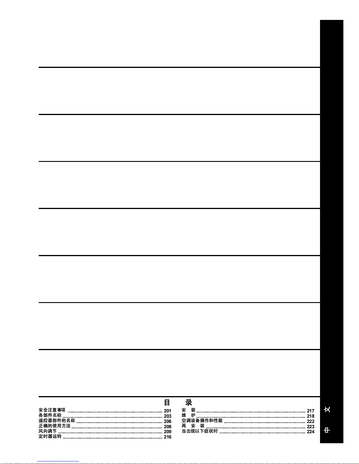
CONTENTS
SOMMAIRE
INHALT
INDICE
CONTENIDO
ÍNDICE
РЕСЙЕЧПМЕНБ
INHOUD
PRECAUTIONS FOR SAFETY .............................................................1
NAME OF EACH PART .........................................................................3
PARTS NAME OF REMOTE CONTROLLER ........................................ 6
CORRECT USAGE................................................................................8
ADJUSTMENT OF WIND DIRECTION.................................................. 9
TIMER OPERATION ............................................................................ 16
INSTALLATION....................................................................................17
MAINTENANCE...................................................................................18
AIR CONDITIONER OPERATIONS AND PERFORMANCE ............... 2 2
RE-INSTALLATION ............................................................................. 23
WHEN THE FOLLOWING SYMPTOMS ARE FOUND ........................ 24
MESURES DE SECURITE .................................................................. 26
NOM DE CHAQUE PIÈCE................................................................... 28
NOM DES PIECES DE LA TELECOMMANDE ................................... 31
UTILISATION CORRECTE ..................................................................33
REGLAGE DU SENS DE SOUFFLAGE .............................................. 34
FONCTIONNEMENT PAR MINUTERIE .............................................. 41
INSTALLATION....................................................................................42
ENTRETIEN......................................................................................... 43
FONCTIONNEMENT ET PERFORMANCES DU CLIMATISEUR ....... 47
REINSTALLATION...............................................................................48
EN PRÉSENCE DES SYMPTÔMES SUIVANTS ................................ 49
SICHERHEITSVORKEHRUNGEN ...................................................... 51
BEZEICHNUNGEN DER TEILE .......................................................... 53
TEILEBEZEICHNUNG DER FERNBEDIENUNG ................................ 56
RICHTIGE HANDHABUNG .................................................................58
EINSTELLUNG DES LUFTSTROMS ..................................................59
ZEITBETRIEB......................................................................................66
INSTALLATION....................................................................................67
WARTUNG ...........................................................................................68
FUNKTIONEN UND LEISTUNG DES KLIMAGERÄTS ......................72
NEU-INSTALLATION........................................................................... 73
VORGEHENSWEISE BEI FOLGENDEN SYMPTOMEN ....................74
PRECAUZIONI PER LA SICUREZZA................................................. 76
NOME DI OGNI PARTE ....................................................................... 78
NOME DELLE PARTI DEL TELECOMANDO .....................................81
USO CORRETTO ................................................................................ 83
REGOLAZIONE DELLA DIREZIONE DELL’ARIA.............................. 84
FUNZIONAMENTO CON TIMER ......................................................... 91
INSTALLAZIONE .................................................................................92
MANUTENZIONE ................................................................................ 93
OPERAZIONI E PRESTAZIONI DEL CONDIZIONATORE D’ARIA....97
RE-INSTALLAZIONE ........................................................................... 98
QUANDO SI RISCONTRANO I SINTOMI SEGUENTI ........................ 99
PRECAUCIONES PARA SU SEGURIDAD .......................................101
NOMBRE DE CADA COMPONENTE ............................................... 103
DESCRIPCIÓN DE LOS BOTONES DEL CONTROL REMOTO ......106
UTILIZACIÓN CORRECTA................................................................108
AJUSTE DE LA DIRECCIÓN DEL AIRE .......................................... 109
FUNCIONAMIENTO DEL TEMPORIZADOR.....................................116
INSTALACIÓN ................................................................................... 117
MANTENIMIENTO ............................................................................. 118
FUNCIONES Y RENDIMIENTO DEL APARATO DE AIRE
ACONDICIONADO ............................................................................122
REINSTALACIÓN .............................................................................. 123
CUANDO SE DETECTAN LOS SIGUIENTES SÍNTOMAS...............124
PRECAUÇÕES DE SEGURANÇA.................................................... 126
NOMES DE CADA PEÇA..................................................................128
NOME DAS PEÇAS DO CONTROLADOR REMOTO.......................131
UTILIZAÇÃO CORRECTA ................................................................133
REGULAÇÃO DA DIRECÇÃO DO VENTO.......................................134
OPERAÇÃO DO TEMPORIZADOR .................................................. 141
INSTALAÇÃO .................................................................................... 142
MANUTENÇÃO ................................................................................. 143
FUNCIONAMENTO E PERFORMANCE DO APARELHO DE AR
CONDICIONADO...............................................................................147
REINSTALAÇÃO ............................................................................... 148
SE FOREM DETECTADOS OS SEGUINTES SINTOMAS ............... 149
VOORZORGSMAA TREGELEN V OOR UW VEILIGHEID ................. 151
BENAMINGEN VAN DE ONDERDELEN...........................................153
BENAMING VAN DE ONDERDELEN VAN DE
AFSTANDSBEDIENING .................................................................... 156
CORRECT GEBRUIK ........................................................................ 158
INSTELLEN VAN DE LUCHTSTROOMRICHTING ...........................159
DE TIMER GEBRUIKEN.................................................................... 166
INSTALLEREN .................................................................................. 167
ONDERHOUD....................................................................................168
BEDIENING EN WERKING VAN DE AIRCONDITIONER .................172
OPNIEUW INSTALLEREN ................................................................173
WANNEER DE VOLGENDE SYMPTOMEN AANWEZIG ZIJN ......... 174
РСПЦХЛБОЕЙУ ГЙБ БУЦБЛЕЙБ ....................................................... 176
ПНПМБУЙБ ФПХ КБИЕ ЕОБСФЗМБФПУ ........................................ 178
ПНПМБУЙБ ФМЗМБФЩН ФПХ ФЗЛЕЧЕЙСЙУФЗСЙПХ ...................... 181
ПСИЗ ЧСЗУЗ ..................................................................................... 183
СХИМЙУЗ ФЗУ КБФЕХИХНУЗУ ФПХ БНЕМПХ .............................. 184
ЛЕЙФПХСГЙБ ЧСПНПДЙБКПРФЗ ...................................................... 191
ЕГКБФБУФБУЗ .................................................................................. 192
УХНФЗСЗУЗ ....................................................................................... 193
ЛЕЙФПХСГЙЕУ КБЙ БРПДПУЗ ФПХ КЛЙМБФЙУФЙКПХ .................... 1 97
ЕГКБФБУФБУЗ ЕК НЕПХ ................................................................. 198
ПФБН РБСБФЗСЗИПХН ФБ РБСБКБФЩ УХМРФЩМБФБ ........... 199
1
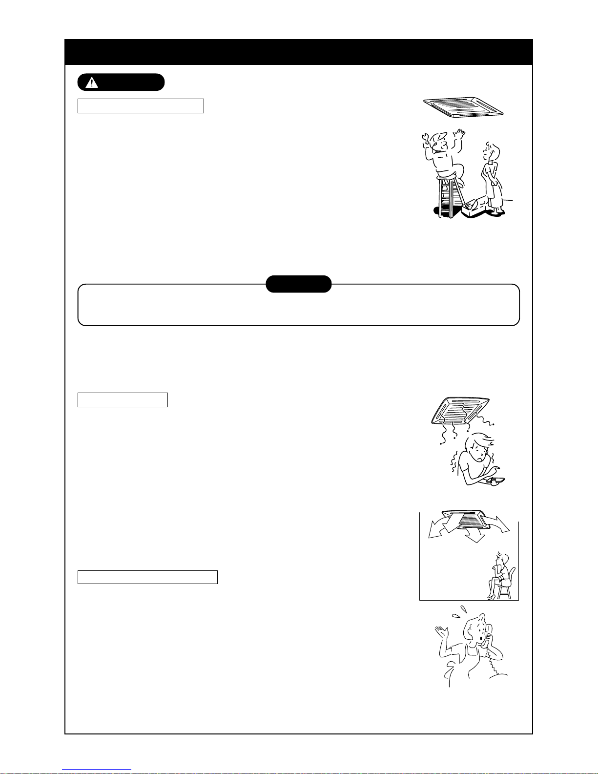
SAFETY PRECAUTIONS
WARNING
Warning on installation
Ensure the unit is installed by qualified personnel.
Specialist knowledge and technology is required to install the unit.
Do not perform the installation by yourself. If an incomplete installation is per-
formed, a fire, electric shock, injury, or water leakage may be caused.
For products that are sold separately, ensure they meet the Toshiba
specification.
For products sold separately, be sure to use those specified by Toshiba.
Otherwise, a fire, electric shock or water leakage ma y occur. For installation
work, leave it to special engineer.
When installing the unit inside a small room, take precautions so that the
refrigerant will not exceed the critical concentration if a leak occurs.
Warning on use
Do not expose your body directly to excessive cool air for long
periods of time.
May effect your physical condition, causing possible health problems.
Never insert a finger or another object into the air inlet port or the air
outlet port of the air conditioner.
Since the fan rotates at a high speed inside the unit, a possible injury may be
caused.
If a fault/error (burnt smell, etc.) occurs, stop the operation, turn off
the power switch and contact the dealer who you
purchased the air conditioner from.
If the unit is allowed to keep running, a fire or electric shock could occur.
Warning on moving/repair
Do not modify the air conditioner in anyway.
As a fire or electric shock may occur.
If the unit requires maintenance or repair, contact the dealer who you
purchased the air conditioner from.
If an incomplete repair is performed, a fire or electric shock may be caused.
When moving or re-installing the air conditioner, contact the dealer
who you purchased the air conditioner from or contact a suitable
engineer.
If an incomplete installation is performed, a fire, electric shock, injury or water
leakage may occur.
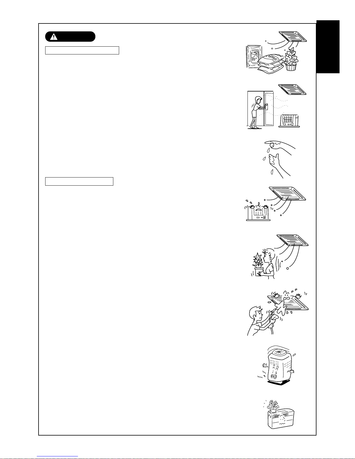
CAUTION
Ensure that the unit is installed correctly by a trained engineer . If the unit is incorrectly installed, refrigerant
may leak causing possible oxygen deficiency.
Ensure that the unit is earthed correctly.
The unit must be earthed correctly , if not an electric shoc k may occur. (for details conform to your local building regulations)
2
CAUTION
Caution on installation
Ensure that the drain pipe is installed so that the water can run
freely and without leakage.
If the piping is fitted incorrectly, water may drip , causing possible damage to
furniture, carpets etc.
Check the earth leakage breaker is installed.
It is necessary to attach an earth leakage breaker. Otherwise, you have no
protection against a possible electric shock.
Check the air conditioner is installed in a place where flammable
gases will not leak.
If gas leaks and accumulates in the unit surroundings, an outbreak of fire
may be caused.
Check the outdoor unit is fixed securely to the base.
If it is not fixed securely to the base, the unit may become unstable and fall,
causing possible injury.
Check fixing method
Do not clean the air conditioner with water.
An electric shock may be caused.
Ensure items that are combustible are not placed in the direction
where the air conditioner will flow directly.
Imperfect combustion of the combustible items may occur.
If there are combustible items within the room, ensure that the
room has adequate ventilation, while the air conditioner is in
operation.
If ventilation is inadequate a shortage of oxygen may occur.
Check that the installation plate, etc. is not damaged by long
term use of the air conditioner.
If the installation location deteriorates sufficiently, then the unit may become
unstable and fall, resulting in possib le injury.
Do not put either plants or animals in a location, where the air
conditioner flows air directly.
An adverse eff ect may occur, resulting in possible damage or injury to the
plant/animal.
Do not locate or spray flammable gases etc. near or directly at the
air conditioner.
A fire may be caused.
Do not put vessels containing water such as a vase on the unit.
Moisture may enter the unit, causing a deterioration of the units electrical
isolation properties, causing a possible electric shock.
Do not handle the switches with wet hands.
An electric shock may be caused.
Do not use the air conditioner for special purpose such as storage of foods, plants and animals, precise equipment and art
works.
Deterioration or damage to the goods may occur .
ENGLISH
3
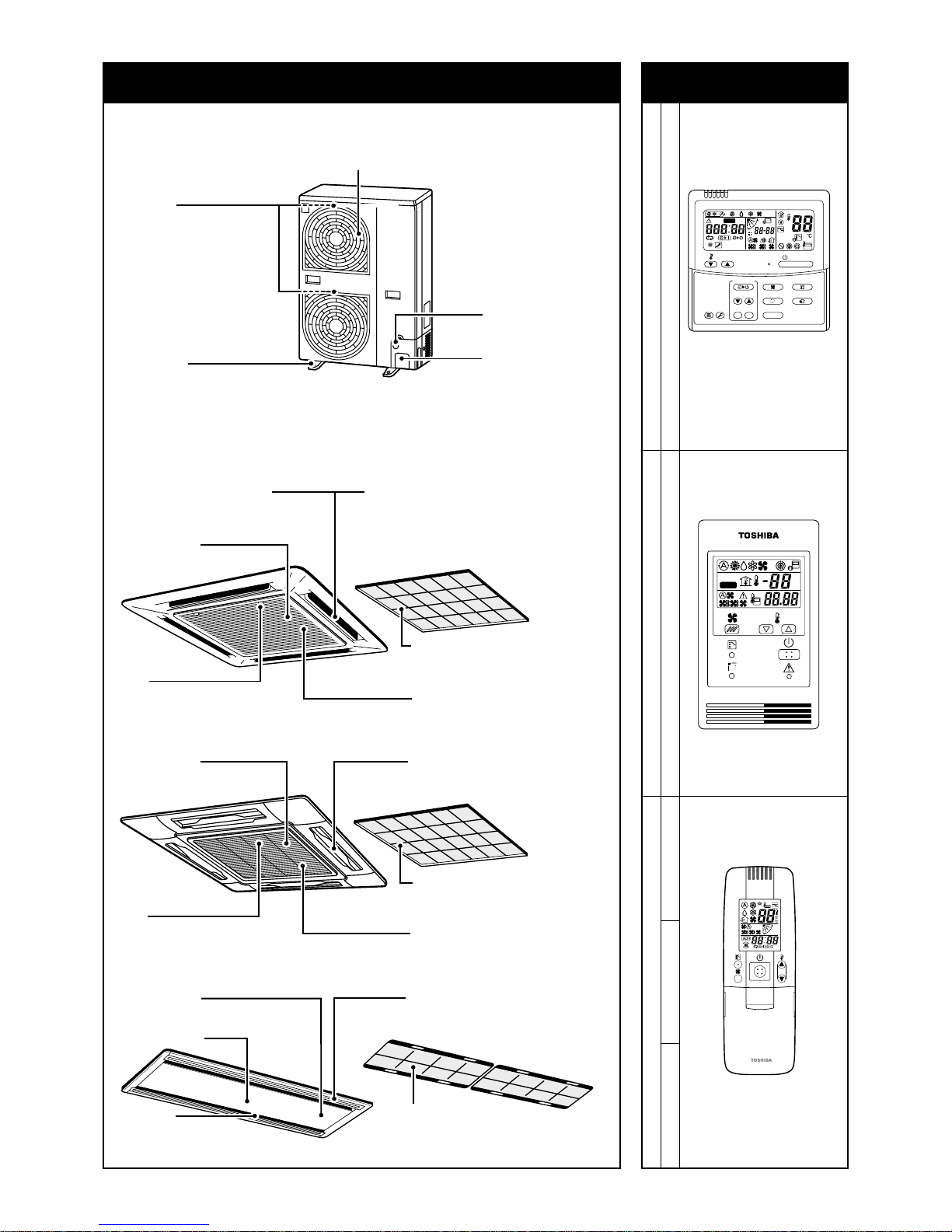
2-way discharge/3-way discharge
2-way discharge or 3-way discharge can be
selected according to the shape or
arrangement of the room.
For details, consult with the dealer which you
have purchased the air conditioner.
Air outlet/Air outlet flap
Select air blow direction in cooling or
heating operation each.
Earth screw
It is included in the electric
parts box.
Air outlet/Air outlet flap
Select air blow direction in cooling or
heating operation each.
Air filter
Removes dust and trash.
(Air filter is provided in the air grille.)
Air inlet grille
Air in the room is sucked from here.
Clip
The clip is to open/close the
air inlet grille.
Air inlet
Air in the room is
sucked from here.
Air filter
Removes dust and trash.
(Air filter is provided in the center panel.)
Earth screw
It is included in the electric parts box.
Center panel
Air outlet/Air outlet flap
Select air blow direction in cooling or
heating operation each.
Indoor unit
[4-way Air Discharge Cassette Type]
MMU-AP0091H, AP0121H, AP0151H, AP0181H, AP0241H,
MMU-AP0271H, AP0301H, AP0361H, AP0481H, AP0561H
[2-way Air Discharge Cassette Type]
MMU-AP0071MH, AP0091MH, AP0121MH, AP0151MH, AP0181MH
Air inlet
They are provided at front,
rear, left, and right sides.
Fixing leg
Air outlet (Discharge)
Hot air is discharged when cooling operation is performed.
Cold air is discharged when heating operation is performed.
Power source hole
Refrigerant pipe
connecting hole
Connecting valve is
included inside here.
Outdoor unit
Air filter
Removes dust and trash.
(Air filter is provided in the air grille.)
Air inlet grille
Air in the room is sucked from here.
Clip
The clip is to open/close the
air inlet grille.
Earth screw
It is included in the electric
parts box.
ON / OFF
FAN
TEMP.
SWING/FIXTIME
MODE
VENT
UNITSET CL
FILTER
RESET
TEST
TIMER SET
CODE No.
UNIT No.
TEST
SETTING
DATA
SET
R.C. No.
H
˚C
TEST
SETTING
NAME OF EACH PART Sold Separately Pa rts
Wired remote controller
RBC-AMT31E
Simple wired remote controller
RBC-AS21E2
Wireless remote controller kit
TCB-AX21E2 RBC-AX22CE2 RBC-AX21U(W)-E2
4
WEEKLY TIMER
ERROR
SuMoTuWeTh FrSa
PROGRAM1
PROGRAM2
PROGRAM3
SELECT ZONE
CL
SET
GROUP
CODE
No.
UNIT No.
No.
R.C.
TEST
ZONE
ALL
ZONE
GROUP
SETTING
1234
SET DATA
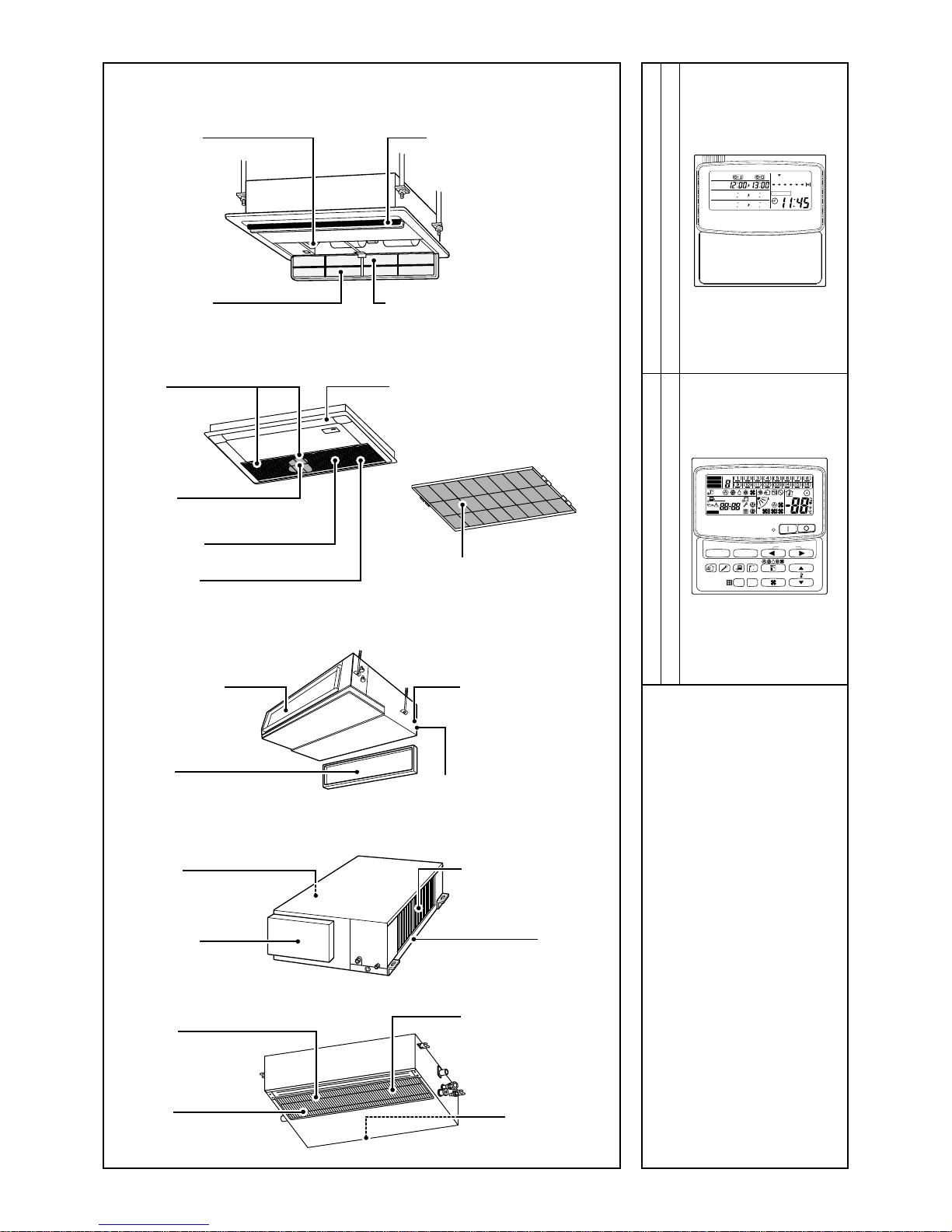
Weekly timer
RBC-EXW21E2
Central remote controller
TCB-SC642TLE2
Earth screw
It is included in the
electric parts box.
Air outlet/
Air outlet flap
Select air blow direction incooling
or heating operation each.
Air inlet grille
Air in the room is sucked from here.
Air filter
Removes dust and trash.
(Air filter is provided in the air inlet grille.)
[1-way Air Discharge Cassette Type]
MMU-AP0071YH to AP0121YH
MMU-AP0152SH, AP0182SH, AP0242SH
Button
Button to open/close
suction port
Air outlet/Air outlet flap
Change the direction of the air to be
discharged according to cool/heat mode.
Air filter
Removes dust or trash.
(Provided on the suction port.)
Suction port
Sucks air inside of the room from here.
Earth screw
It is included in the electric parts box.
Air filter
Removes dust or trash.
(Provided on the suction port.)
[Concealed Duct Standard Type]
[Concealed Duct High Static Pressure Type]
[Slim Duct Type]
Air outlet flange
Discharge duct is
connected.
Earth screw
Earth screws are provided
in the electric parts box.
Air filter
Removes dust and trash.
(Air filter is provided in the air inlet grille.)
Air inlet
Air in the room is sucked from here.
Air outlet
Discharge duct is connected.
Air inlet
Suction duct is connected.
Earth screw
Earth screws are provided
in the electric parts box.
Drain pan
Air inlet
Suction duct is connected.
Earth screw
It is included in the electric
parts box.
Air filter
(Air filter is not provided to
some models in the series.)
Air outlet
Discharge duct is
connected.
5
Air outlet/Air outlet flap
Exchanges the air direction according to
cooling or heating time.
Earth screw
It is prepared in the electric parts box.
Air inlet port
Sucks air inside of the room from here.
Air filter
Removes dirt or dust.
(It is included in the suction port.)
Air outlet port
Drain pan (With drain filter)
This accessory is installed at the local site.
Air filter
Removes dirt or dust.
(It is included in the suction port.)
Air inlet port
Sucks air inside of the room from here.
Earth screw
It is prepared in the electric parts box.
Earth screw
It is prepared in the electric parts box.
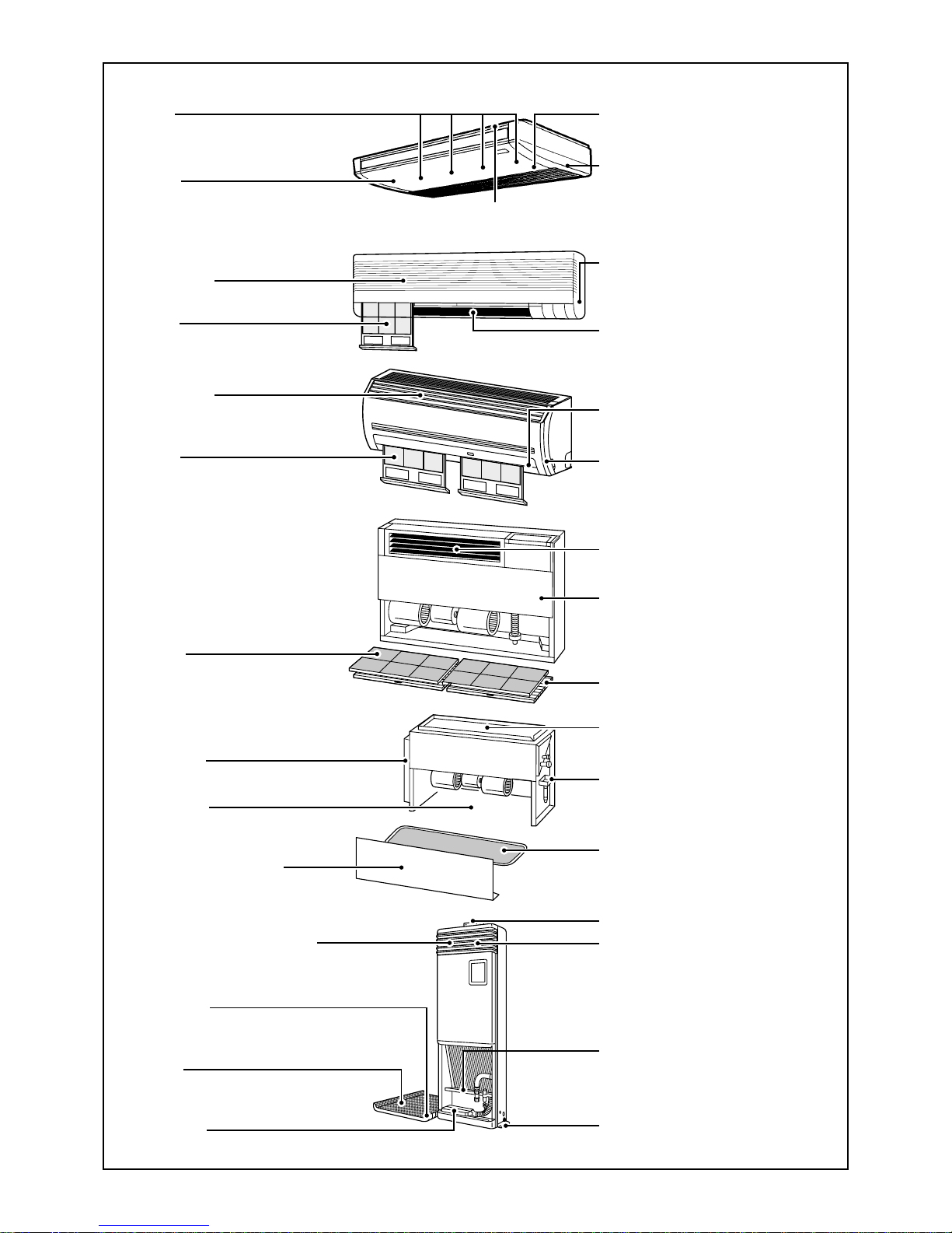
Front panel (Lower side)
Fixing metal holder
Vertical flap
The air can be automatically discharged
rightward/leftward at stated periods.
Horizontal flap/Air outlet port
Exchanges the air direction according
to cooling or heating time.
Air filter
Removes dirt or dust.
Air inlet port
Sucks air inside of the room from here.
Fixing metal holder (Right and left)
Drain pan
Water accumulated in the drain pan is
drained from here through the drain pipe.
[Under Ceiling Type]
[High Wall T ype]
MMK-AP0071H to AP0241H
MMK-AP0072H to AP0122H
Air inlet grille
Air in the room is sucked from here.
Earth screw
Earth screws are provided in the electric
parts box.
Air filter
Removes dust and trash.
(Air filter is provided in the air inlet grille.)
Air outlet/Air outlet flap
Change the direction of the air to be
discharged according to cool/heat mode.
Button
Button to open/close the suction port
Air filter
Removes dust or trash.
(Provided on the suction port.)
Air inlet port
The air in the room is sucked in from this
port.
Earth screw
Earth screws are provided in the electric
parts box.
Air outlet/Air outlet flap
Change the direction of the air to be discharged according to cool/heat mode.
Air inlet grille
Air in the room is sucked from here.
Earth screw
Earth screws are provided in the electric
parts box.
Air outlet/Air outlet flap
Change the direction of the air to be
discharged according to cool/heat mode.
Air filter
Removes dust and trash.
(Air filter is provided in the air inlet grille.)
[Floor Standing Type]
[Floor Standing Concealed Type]
[Floor Standing Cabinet Type]

6
Display
section
Operation
section
ON / OFF
FAN
TEMP.
SWING/FIXTIME
MODE
VENT
UNITSET CL
FILTER
RESET
TEST
TIMER SET
CODE No.
UNIT No.
TEST
SETTING
DATA
SET
R.C. No.
H
2
15
5
78 9
3
1
4
6
10
11
13
16
12
14
17
CODE No.
UNIT No.
TEST
SETTING
DATA
SET
R.C. No.
H
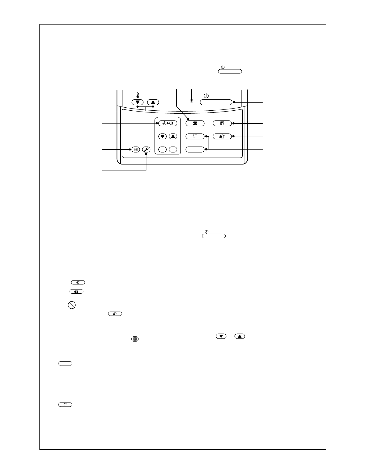
PARTS NAME OF REMOTE CONTROLLER
Display section
In the display example, all indicators are displayed for the explanation.
In reality only, the selected contents are displayed.
• When turning on the leak breaker for the first time, [SET DATA] flashes on
the display part of the remote controller. While this display is flashing, the
model is being automatically confirmed. After the [SET DATA] display has
disappeared, you may use the remote controller.
1
SET DATA displa y
Displayed during the setup of the timer.
2
Operation mode select display
The selected operation mode is displayed.
3
CHECK display
Displayed while the protective device works
or a fault/error occurs.
4
Timer time display
Time on the timer is displayed.
(When a fault/error occurs, the check code is
displayed.)
5
Timer setting setup display
When pushing the Timer setting button, the
display on the timer is selected in order of
[OFF]
→ [OFF] repeat OFF timer
→ [ON]
→ No display.
6
Filter display
If “FILTER ” is displayed, clean the air
filter.
7
TEST run display
Displayed during a test run.
8
Flap position display
(for 4-Wa y Air Dischar ge Cassette Type and
Under Ceiling T ype model only)
Displays flap position.
9
SWING display
Displayed during the up/down movement of the
flap.
10
Set up temperature display
The selected set up temp. is displayed.
11
Remote controller sensor display
Displayed while the sensor on the remote
controller is used.
12
PRE-HEA T displa y
(for Heat-pump model only)
Displayed when the heating operation starts or a
defrost operation is carried out.
While this indication is displayed, the indoor fan
will stop or will go into LOW mode.
13
Operation ready display
Displayed when cooling or heating operation is
impossible because the outdoor temperature goes
out of the operable range.
14
No function display
Displayed if there is no function even when the
button is pushed.
15
Air volume select display
The selected air volume mode is displayed.
(AUTO)
(HIGH)
(MED.) (LOW)
In the Concealed Duct High Static Pressure type
models, [HIGH] only is displayed for the air speed.
16
Mode select control display
Displayed when pushing the “Operation mode
select
” button while the operation mode is
fixed in heating or cooling mode by the system
manager of the air conditioner.
17
Central control display
Displayed when using the remote controller together with a central control remote controller.
If the Remote controller is prohibited at the central
control side,
flashes when operating the
ON / OFF
,
MODE
, / buttons. The change
will not be accepted.
(The contents available to be set up on the remote
controller differ according to the central control
mode. For details, refer to Owner’s Manual of the
central control remote controller.)
7
1
7
3
5
2
8
9
6
4
10
ON / OFF
FAN
TEMP.
SWING/FIXTIME
MODE
VENT
UNITSET CL
FIL TER
RESET
TEST
TIMER SET
Operation section
Push each button to select a desired operation.
This remote controller can operate a maximum of 8 indoor units.
• Before the unit can begin operation, it is firstly necessary to set the units operating parameters. After this
has been completed the air conditioner can be used by pushing the
ON / OFF
button only.
1
Air volume select button
Selects the desired air volume mode.
For the Concealed Duct High Static Pressure
type models this function is unavailable.
2
Timer set button
The TIMER SET button is used when the timer
is set up.
3
Check button
The CHECK button is used to check the units
operation. During normal operation, do not use
this button.
4
Fan
VENT
button
The
VENT
button is used when a fan which is
sold on the market is connected.
• If is displayed on the remote controller
when pushing the
VENT
button, a fan is not
connected.
5
Filter reset button
Resets (Erases) the “FILTER ” display.
6
Air flow direction and Swing function
UNIT
:
If there are multiple indoor units that are controlled by a single remote controller , simply
select each unit in turn for which you wish to
adjust the air flow direction.
SWING/FIX
:
Set up the auto swing and the angle of the flap.
• This function is not provided on the Concealed
Duct Standard Type, High Static Pressure
Type, Floor standing Cabinet Type, Floor
Standing Concealed Type, or Slim Duct Type.
7
Operation lamp
The light will be ON when the unit is in operation and OFF when the unit is not being used.
Note) The light will flash if a protective device
has been operated or if the timer function has
an error.
8
ON / OFF
button
When the button is pushed, the operation
starts. If the button is pressed again, the unit
operation will stop.
When the unit operation has stopped, the
operation lamp and all of the displays will
disappear.
9
Operation select button
Selects the desired operation mode.
10
Set up temperature button
Adjusts the room temperature.
Set the desired set temperature by pushing
the or buttons.
OPTION :
Remote controller sensor
In normal installations the temperature of the room
is sensed by a temperature sensor on the indoor
unit. However it is possible to have the sensor
within your remote controller . For further details
please contact your local dealer .
• In cases where one remote controller controls the
multiple indoor units, the setup operation is
unavailable in group control.
8
1
3
2
4
ON / OFF
FAN
TEMP.
SWING/FIXTIME
MODE
VENT
UNITSET CL
FILTER
RESET
TEST
TIMER SET
HEAT DRY COOL FAN
Heat-pump model
DRY COOL FAN
Cooling only model
(Dehumidity)
LOW MED. HIGH
AUTO
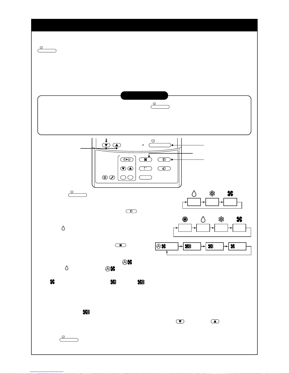
CORRECT USAGE
When you use the air conditioner for the first time or when y ou change the SET DATA value, follow the procedure shown below . For consequent uses the display on the remote controller can be turned on by pushing the
ON / OFF
button only.
Preparation
Turn on the main power supply and/or the leakage breaker.
• When the power supply is turned on, a partition line is shown on the display part of the remote controller.
Note) When the po w er supply is turned on, the remote controller will not accept any operational inputs until
approximately 1 minute has passed. This is not a failure of the unit.
REQUIREMENT
• While using the air conditioner, only operate it with the
ON / OFF
button. Do not turn it off with the main
power switch or the leakage break er.
• Do not turn off the leakage breaker while the air conditioner is in use.
• T urn on the leakage breaker 12 hours or more before the air conditioner is to begin operation or if the
system has not been in use for long periods of time.
1
Push the
ON / OFF
button.
The operation lamp goes on, and the operation will start.
2
Select an operation mode with the
MODE
button.
One push of the button, and the display
changes in the order shown on the right.
•“DRY mode” function is not provided on the
Concealed Duct High Static Pressure Type.
3
Select the air volume with the
FAN
button.
One push of the button, and the display
changes in the order shown on the right.
• When the air volume is set to “AUTO ”, the air volume will differ according to the room temper ature .
• In DRY mode, the “AUTO ” symbol will be displayed and the air volume will be LOW.
• In heating operation, if the room temperature is not heated sufficiently with the air volume set at “LOW
” operation, select the “MED. ” or “HIGH ” operation.
• The temperature sensor for the indoor unit is located near to the air inlet opening and therefore will differ
slightly from the actual room temperature. This difference ma y be increased/decreased depending on the
type of room and its design. (Automatic air speed cannot be selected in F AN mode .)
• The Air Volume function is not provided on the “Concealed Duct High Static Pressure T ype” instead the
air speed “HIGH ” symbol is displayed.
4
Determine the set up temperature by pushing the “TEMP. ” or “TEMP. ” button.
Stop
Push the
ON / OFF
button.
The operation lamp goes off and the unit will stop.

9
REQUIREMENT
[In Cooling operation]
• The operation will start after approximately 1 minute.
[In Heating operation (For Heat-pump model only)]
• In heating operation, the fan operation may continue for approximately 30 seconds after the air conditioner has stopped.
• The indoor fan will continue the preheat operation for 3 to 5 minutes under stop conditions. The indoor
unit will then begin to blow out hot air.
(
symbol on the remote controller display will come on.)
• When the temperature of the room has reached the setup temperature and the outdoor unit stops, the air
speed reduces and so the air volume will decrease.
• In HEA T mode, if the room temperature reaches the set temperature, the outdoor unit will stop and
the air flow / volume will decrease.
• In the defrost mode, the fan will stop so that cool air is not discharged and the PRE-DEF is displayed.
ADJUSTMENT OF WIND DIRECTION
To increase the cooling or heating effect, be sure to use the discharge flap in different directions when in cooling or heating operation.
The characteristics of air are such that cold air will accumulate in the lower half of the room, while hot air will
accumulate in the upper half.
CAUTION
Set the flap horizontally in cooling operation.
If a cooling operation is performed with a downwards discharge, the surf ace of the discharge port or flap
will become wet with dew, and water may drip down.
REQUIREMENT
• If a heating operation is performed with a horizontal discharge, unevenness the room temperature may
not be equal i.e. there may be a large variance between one side of the room with the other.
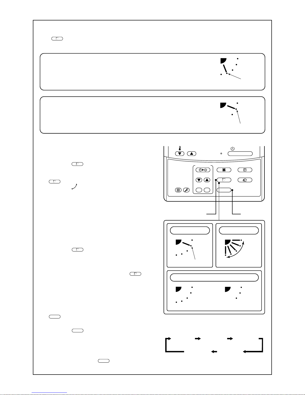
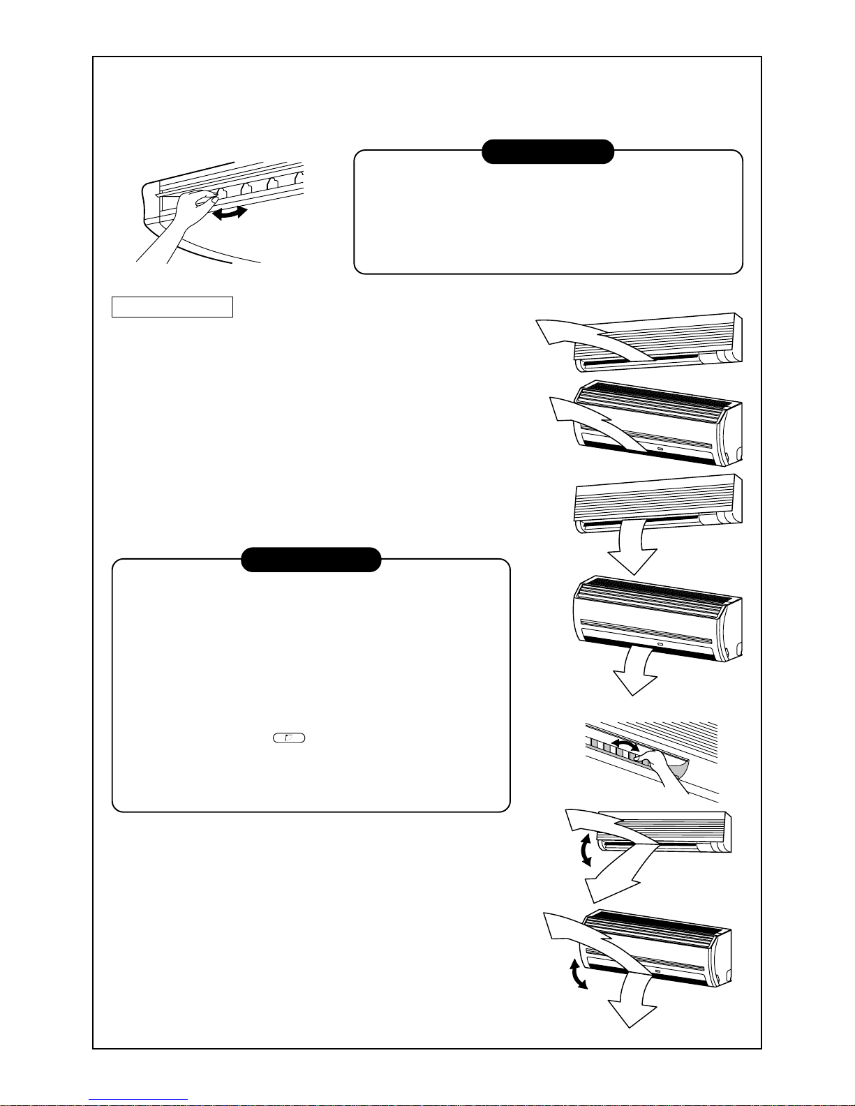
4-way Air Discharge Cassette Type
• When the air conditioner is not in operation, the
discharge flap will automatically directs downwards.
• When the air conditioner is in ready status for heating, the discharge flap will be directed upwards.
The swinging operation will begin after heating
ready status has been cleared. Please note the
“SWING
” symbol will still be displayed on the
remote controller even when the unit status is ready
to begin the heating operation.
[In Cooling operation]
Use the discharge flap with a horizontal set point.
[In Heating operation (For Heat-pump model only)]
Use the discharge flap with a downwards set point.
10
Initial setup
Initial setup
ON / OFF
FAN
TEMP.
SWING/FIXTIME
MODE
VENT
UNITSET CL
FIL TER
RESET
TEST
TIMER SET
In FAN operation
1, 2, 3 4
In all modes
Display when stopping the swing
Initial setup
Series of
operation
Fan/Heat
operation
Cool/Dry
operation
Unit No. 1-1No display Unit No. 1-2
Unit No. 1-4 Unit No. 1-3
How to set up the air direction
Push
SWING/FIX
button.
1
Every pushing the button, the air direction changes.
In Heating operation
Set the air outlet flap downward.
If directing it upward, the hot air may not come to the foot.
How to adjust the the air flow direction,
using the swinging function
2
Push the
SWING/FIX
button.
Set the direction of the air outlet flap to
the lowest position and then push the
SWING/FIX
button again.
• [SWING ] is displayed and the air flow
direction will automatically change either
upwards/downwards.
In the case where one remote controller controls multiple indoor units, each indoor unit can
be selected and its air flow direction can be
adjusted.
How to stop the flap from swinging
3
Push the
SWING/FIX
button again while the
horizontal flap is moving.
• The horizontal flap can be stopped at any
position desired. If you wish to return the flap to
it original upwards position, press the
SWING/FIX
button again.
* During the cooling/drying operation the hori-
zontal flap will not stop at its most downwards
facing position 9 (reduce the risk of water
dripping), but will instead move to the 3rd
position from the top (as shown in the figure).
4
UNIT
• T o set up the air flo w direction individually,
push the
UNIT
button to display each indoor
unit No. in a group control. You can then set the
air flow direction for the displayed indoor unit.
• If there is no display, all the indoor units can be
operated collectively.
• For every push of the
UNIT
button, the display
will alter between units as shown in the figure.
In Cooling / Dry operation
Set the air outlet flap Upwards.
If directing it downwards, the dew may form on the near side of the air discharge
port and could drip.

11
ON / OFF
FAN
TEMP.
SWING/FIXTIME
MODE
VENT
UNITSET CL
FILTER
RESET
TEST
TIMER SET
1, 2 3
Unit No. 1-1No display Unit No. 1-2
Unit No. 1-4 Unit No. 1-3
Based on the shape or arrangement of the room, the cold air and hot air can be discharged in two directions or
three directions. For details, please contact your local dealer.
INFORMATION
• If cooling operation is performed with a downwards discharge, dew may form on the surface of the
cabinet or the horizontal flap resulting in dripping.
• If heating operation is performed with a horizontal discharge, the room temperature may not be equal i.e.
there may be a large variance between one side of the room with the other.
• Do not move the horizontal flap directly with your hands; otherwise a fault maybe caused. Select the
direction of the horizontal flap using the flap operation switch on the remote controller . The horizontal flap
will not stop immediately, even if the switch is pushed.
Note) Pushing the switch again when the required louver direction has been reached will stop the louv er.
2-way Air Discharge Cassette Type
[In Cooling operation]
Use the air outlet flap with a horizontal set point.
[In Heating operation (For Heat-pump model only)]
Use the air outlet flap with a downwards set point.
Setup of air flow direction and swinging function
1
Push the
SWING/FIX
button during operation.
• [SWING ] is displayed and the air flow direction will automatically change either upwards/downwards.
In the case of one remote controller that controls multiple indoor units, each indoor unit can be selected
and its air flow direction can be adjusted.
2
Push the
SWING/FIX
button again during the swinging
of the air outlet flap.
• The air outlet flap will be stopped at the desired position.
3
UNIT
• T o set up the air flo w direction individually, push the
UNIT
button to display each indoor unit No. in a group
control. You can then set the air flow direction for the
displayed indoor unit.
• If there is no display , all the indoor units can be operated collectively.
• For every push of the
UNIT
button, the display alters
between units, as shown in the figure.
1-way Air Discharge Cassette Type
Adjustment of air flow direction upwards/downwards
[In Cooling operation]
In cooling operation, use the air outlet flap with a horizontal set point
so that the cold air diffuses the whole room.
[In Heating operation (For Heat-pump model only)]
In heating operation, use the air outlet flap with a downwards set
point so that the hot air is directed towards the floor.
Adjustment of air flow direction rightwards/leftwards
To change the discharge direction to right or left side, set the ve rtical grille inside of the air outlet flap to the desired direction.
Setup the air flow direction and swinging function
Refer to the description of the “2-w ay Air Discharge Cassette Type”.
12
Initial setup
Initial setup
ON / OFF
FAN
TEMP.
SWING/FIXTIME
MODE
VENT
UNITSET CL
FILTER
RESET
TEST
TIMER SET
In FAN operation
1, 2, 3 4
In all modes
Display when stopping the swing
Initial setup
Series of
operation
Fan/Heat
operation
Cool/Dry
operation
Unit No. 1-1No display Unit No. 1-2
Unit No. 1-4 Unit No. 1-3
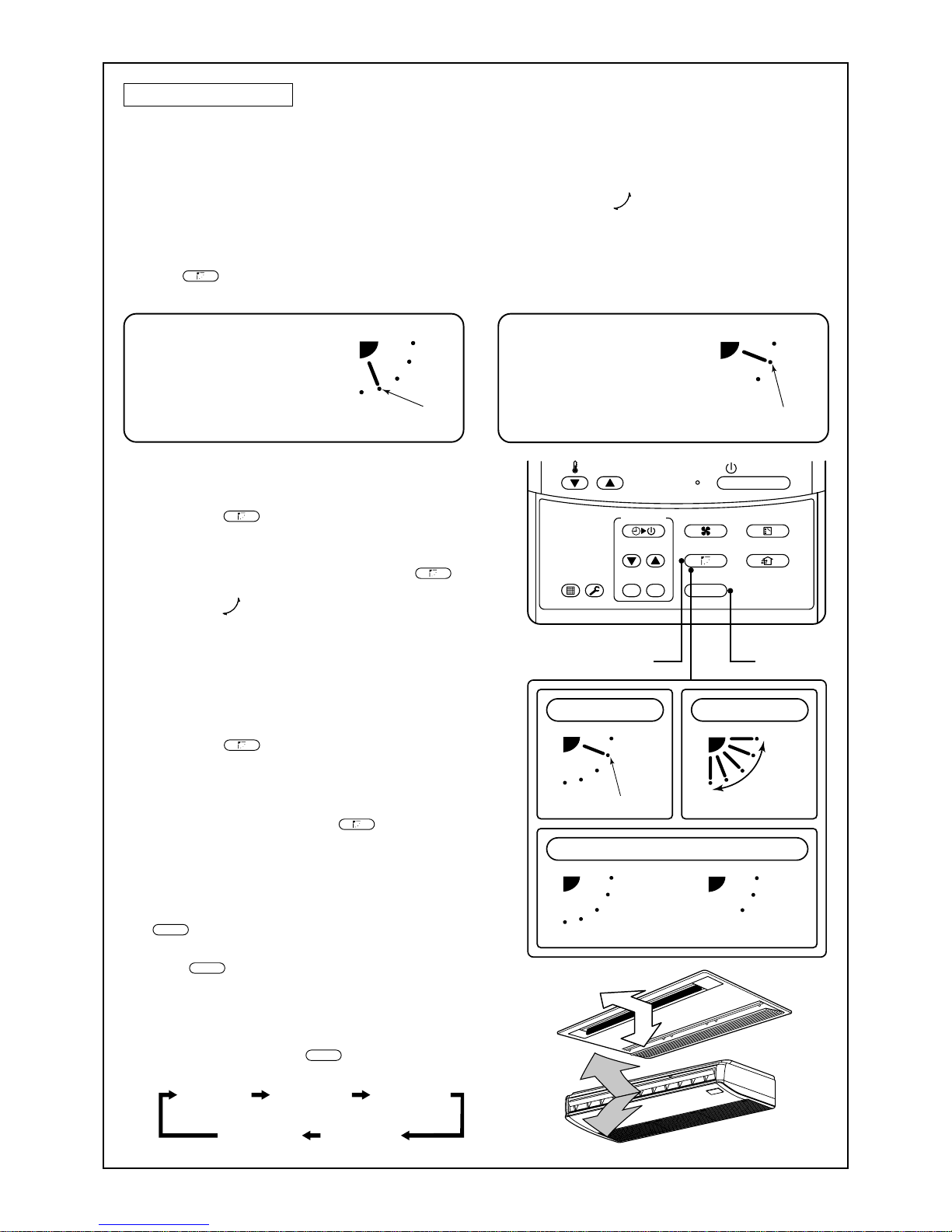
Under Ceiling Type
• While the air conditioner is not in operation, the horizontal flap (Up/Down air direction
adjustment plate) will automatically point upwards.
• When the air conditioner is in ready status for heating, the horizontal flap (Up/Down air
direction adjustment plate) will points upwards. The swinging operation will begin after the
heating ready status has been cleared. Please note the “SWING
” symbol will still be
displayed on the remote controller even when the status is ready to heat.
How to adjust the air flow direction
Push the
SWING/FIX
button during operation.
1
Every time you push the button the air
flow direction will change.
How to adjust the air flow direction, using
the swinging function
2
Push the
SWING/FIX
button.
Set the direction of the horizontal flap (Up/
Down air direction adjustment plate) to its
lowest position and then push the
SWING/FIX
button again.
• [SWING ] is displayed and the air direction will
automatically upwards or downwards.
In cases where one remote controller controls
multiple indoor units, it is possible to set each
indoor unit individually, so that the air flow direction can be altered.
How to stop the louver from swinging
3
Push the
SWING/FIX
button again while the horizontal flap is moving
• The horizontal flap can be stopped at any position
desired. If you wish to return the louvre to it original
upwards position, press the
SWING/FIX
button again.
* During the cooling/drying operation the horizon-
tal flap will not stop at its most downwards
facing position 9 (reduce the risk of water
dripping), but will instead move to the 3rd
position from the top (as shown in the figure).
4
UNIT
• T o set up the air flo w direction individually, push
the
UNIT
button to display each indoor unit No. in
a group control. You can then set the air flow
direction for the displayed indoor unit.
• If there is no display, all the indoor units can be
operated collectively.
• For every push of the
UNIT
button, the display
will alter between units as shown in the figure.
In Cooling / Dry operation
Set the horizontal flap (Up/Down
air direction adjustment plate)
upwards. If directing the air flow
downwards, condensation may
form on the surface of the louver
and may cause water to drip.
In Heating operation
Set the horizontal flap (Up/Down
air direction adjustment plate)
downwards. If the air flow is directed
upwards, the hot air may not reach
the floor, creating an uneven
temperature within the room.
13
Right/Left air direction adjustment
To change the air outlet direction to the right or left side, set the vertical flap located behind the horizontal flap
to the desired direction.
INFORMATION
• If cooling operation is performed with a downwards discharge,
dew may form on surface of the cabinet or the horizontal flap
resulting in possible dripping.
• If heating operation is performed with a horizontal discharge,
the room temperature may not be equal i.e. there may be a
large variance between one side of the room with the other .
High Wall T ype
Adjustment of air flow direction upwards/downwards
[In Cooling operation]
In cooling operation, use the horizontal flap with a horizontal set point
so that the cold air diffuses the whole room.
[In Heating operation (For Heat-pump model only)]
In heating operation, use the horizontal flap with a downwards set
point so that the hot air blows tow ards the floor.
REQUIREMENT
• If cooling operation is performed with the louver set at a downwards position, dew may form on the surface of the cabinet or
the horizontal flap resulting in possible dripping.
• If heating operation is performed with the louver set in a horizontal position, the room temperature may not be equal i.e.
there may be a large variance between one side of the room
with the other.
• Do not move the horizontal flap directly with your hands; otherwise a fault/error may be caused. Select the direction of the
horizontal flap using the
SWING/FIX
button on the remote controller .
The horizontal flap will not stop immediately even if the switch
is pushed.
Note) Pushing the switch again when the required louver direction has been reached will stop the louver .
Adjustment of air flow direction rightwards/leftwards
To change the air outlet direction to the right or left side, set the vertical
flap located behind the horizontal flap to the desired direction.
Setup of air direction and swinging
1H series: Refer to the description of “2-way Air Discharge Cassette
Type”.
2H series: Refer to the description of “Under Ceiling Type, 1-wa y Air
Discharge Cassette Type (2SH Series)”.
14
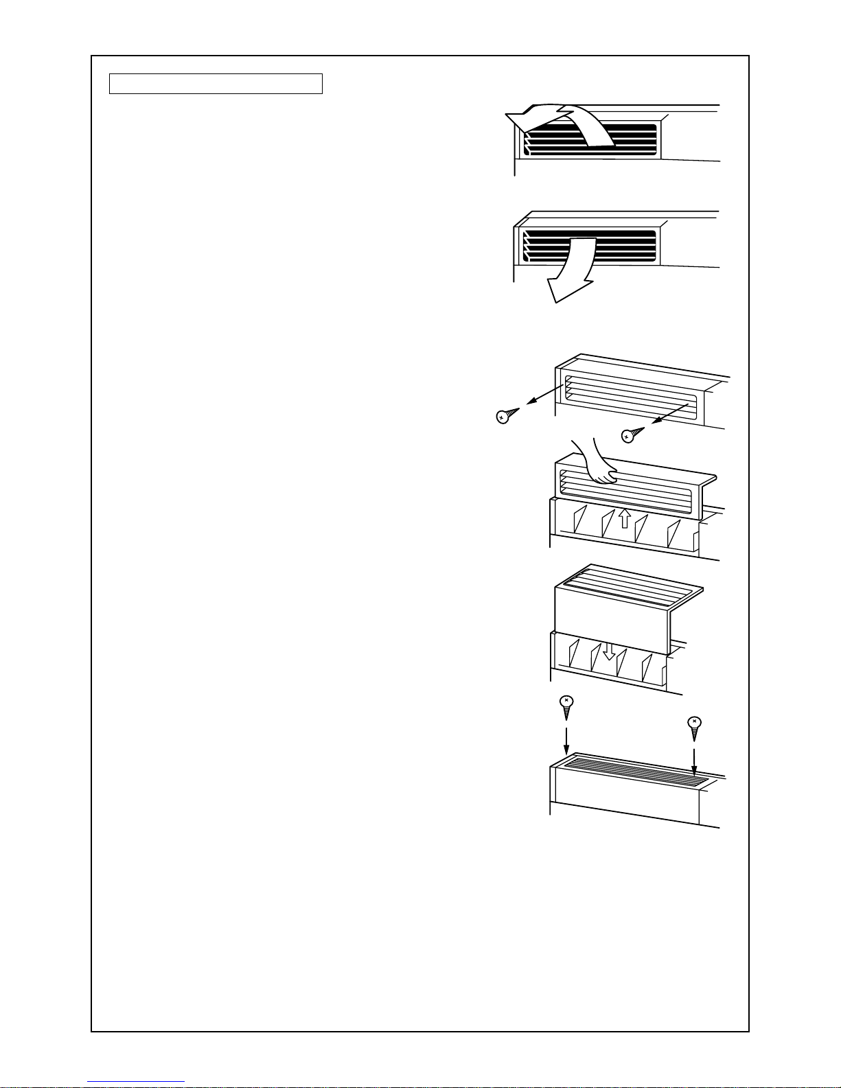
Floor Standing Cabinet Type
[In Cooling operation]
In cooling operation, set the air outlet flap with a horizontal
set point so that the cold air diffuses the whole room.
[In Heating operation (For Heat-pump model only)]
In heating operation, set the air outlet flap with a downwards
set point so that the hot air blows tow ards the floor.
How to change the air outlet port
Change the air outlet port using the following procedure.
1
Remove the two fixing screws on the air outlet
port. (The fixing screws are reused.)
2
Remove the discharge port, by pushing up on
the rear side, to a point where you can remove it
from the rear clip.
3
Lift the air outlet port upwards and remove it.
4
Reverse the air outlet port and attach it to the
main unit.
Pa y attention so that four claw hooks (two at rear and two
at the lower sides) are hooked on the mounting position.
5
Be sure to tighten the air outlet port with the
removed fixing screws so that the air outlet port
does not come off.
15
ON / OFF
FAN
TEMP.
SWING/FIXTIME
MODE
VENT
UNITSET CL
FIL TER
RESET
TEST
TIMER SET
1, 2 3
1
2
In this case, do not use the
swing function.
Unit No. 1-1No display Unit No. 1-2
Unit No. 1-4 Unit No. 1-3
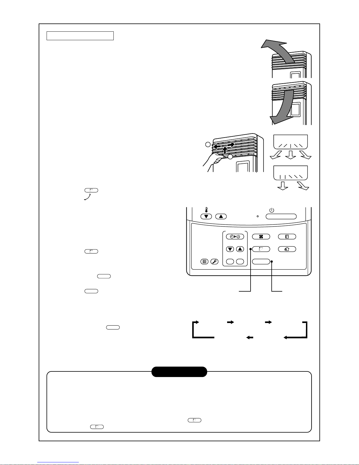
Floor Standing Type
Adjustment of air flow direction upwards/downwards
[In Cooling operation]
In cooling operation, move the flap with your hands so that the horizontal
air outlet points in a direction so that the cold air diffuses the entire room.
[In Heating operation (For Heat-pump model only)]
In heating operation, move the flap with your hands so that the horizontal
air outlet points in a downward direction, towards the floor.
Adjustment of air flow direction rightwards/leftwards
[In case of using unsymmetrical air directions]
Lift up the vertical flap lightly and direct it towards the desired
direction. Once completed lower the flap back down.
In this case, do not use the Swing function.
[In case of automatic swing]
1
Push the
SWING/FIX
button during operation.
• [SWING ] is displayed and the air direc-
tion will automatically change rightwards/
leftwards.
In cases where one remote controller controls multiple indoor units, it is possible to
set each indoor unit individually, so that the
air flow direction can be altered.
2
Push the
SWING/FIX
button again while the
vertical flap is moving will allow you to
stop the louver in the desired position.
3
Swing button
UNIT
• T o set up the air flo w direction individually,
push the
UNIT
button to display each indoor
unit No. in a group control. Then set up the
air flow direction to the desired indoor unit.
• If there is no display, all the indoor units can
be operated collectively.
• Every push of the
UNIT
button, will change
the display as shown in the figure.
INFORMATION
• If cooling operation is performed with downward air outlet, dew may form on the surface of the cabinet or
the horizontal flap, resulting in possible dripping of water.
• If heating operation is performed with the horizontal air outlet actively moving, unevenness of the temperature may increase in the room.
• Do not move the flap directly with your hands during swing operation; otherwise a fault may be caused.
The vertical flap does not stop immediately even if the
SWING/FIX
button is pushed. To adjust the stop posi-
tion, push the
SWING/FIX
button.
16
4
3
2
1
ON / OFF
FAN
TEMP.
SWING/FIXTIME
MODE
VENT
UNITSET CL
FILTER
RESET
TEST
TIMER SET
OFF
(OFF timer) (Repeat OFF timer)
No display
(ON timer)
OFF ON
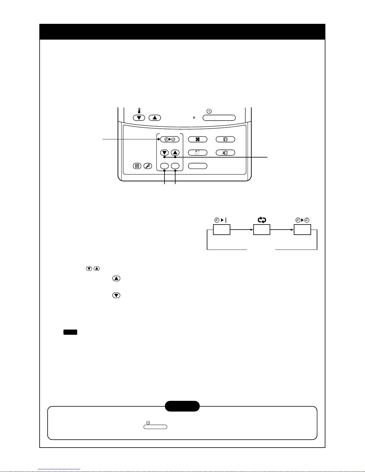
TIMER OPERATION
A type of timer operation can be selected from the following three types.
OFF timer : The operation stops when the time on the timer has reached the set time.
Repeat OFF timer : The unit will stop, every time the set time period has elapsed.
ON timer : The unit will start when the time on the timer has reached the set time.
Timer operation
1
Push the TIMER SET button.
• The timer display (type) changes for every
push of the button.
• SET DATA and timer time displays flash.
2
Push the
TIME
buttons to select the “SET TIME”.
For every push of the button, the set time increases in the unit of 0.5 hr (30 minutes).
The maximum set time is 72.0 hr.
For every push of the button, the set time decreases in the unit of 0.5 hr (30 minutes).
The minimum set time is 0.5 hr.
3
Push the SET button.
•
SETTING
display disappears and timer time display goes on.
When the ON timer is activated, the chosen time period will be displayed. Once the time has been
reached, all displays except the ON light will disappear.
Cancel of timer operation
4
Push the CL button.
• TIMER display will disappear.
NOTICE
• When the unit stops after the timer reached the preset time, the Repeat OFF timer will resume the
operation. However by pushing the
ON / OFF
button the repeat function will stop once the time on the
timer has again reached its set time.
17
INSTALLATION
Installation location
WARNING
• Select a location for installation that will be able to safely support the weight of the unit.
If the installation location is not strong enough to support the unit and the unit falls, injury could result.
CAUTION
• Do not install the unit in a location where combustible gases could conceivably leak.
Leaking gases that accumulate in the vicinity of the unit could be ignited by the unit.
REQUIREMENT
• A location that permits the level installation of the unit
• A location that provides enough space to service the unit safely
• A location where water draining from the unit will not pose a problem
Avoid the following types of locations :
• Locations where salt is present in large amounts (seaside areas), or where sulfuric gases are present in
large amounts (hot springs areas)
(If the unit is to be used in such areas, special maintenance is necessary.)
• Locations that generate oils (including machine oils), steam, oily smoke, or corrosive gases
• Locations where organic solvents are used
• Locations in the vicinity of equipment that generates high frequency signals
• Locations where the outdoor unit will blow in the direction of a neighbor's window
• Locations where the noise of the outdoor unit will pose a problem
• Locations with poor air circulation
Electric wiring
WARNING
Ensure that the unit is correctly earthed.
Grounding is necessary . If earthing is incomplete, an electric shock may be caused.
CAUTION
Check that the circuit breaker is fitted.
Attaching a earth leakage breaker is necessary. Otherwise, an electric shock may be caused.
Make sure that the correct capacity fuses are used.
Using wire or copper wire may cause a fire or unit fault.
Ensure that the power supply to the unit is exclusive and is the correct rated voltage.
To disconnect the appliance from the main power supply.
This appliance must be connected to the main power supply by means a circuit breaker or a switch with a
contact separation of at least 3mm.
18
4-way Air Discharge
Cassette Type
Under Ceiling Type Slim Duct Type
2-way Air Discharge
Cassette Type
Concealed Duct
Standard T ype
1-way Air Discharge
Cassette Type
Concealed Duct
High Static Pressure Type
NO GOOD
NO GOOD
NO GOOD
NO GOOD
NO GOOD
NO GOOD NO GOOD
MAINTENANCE
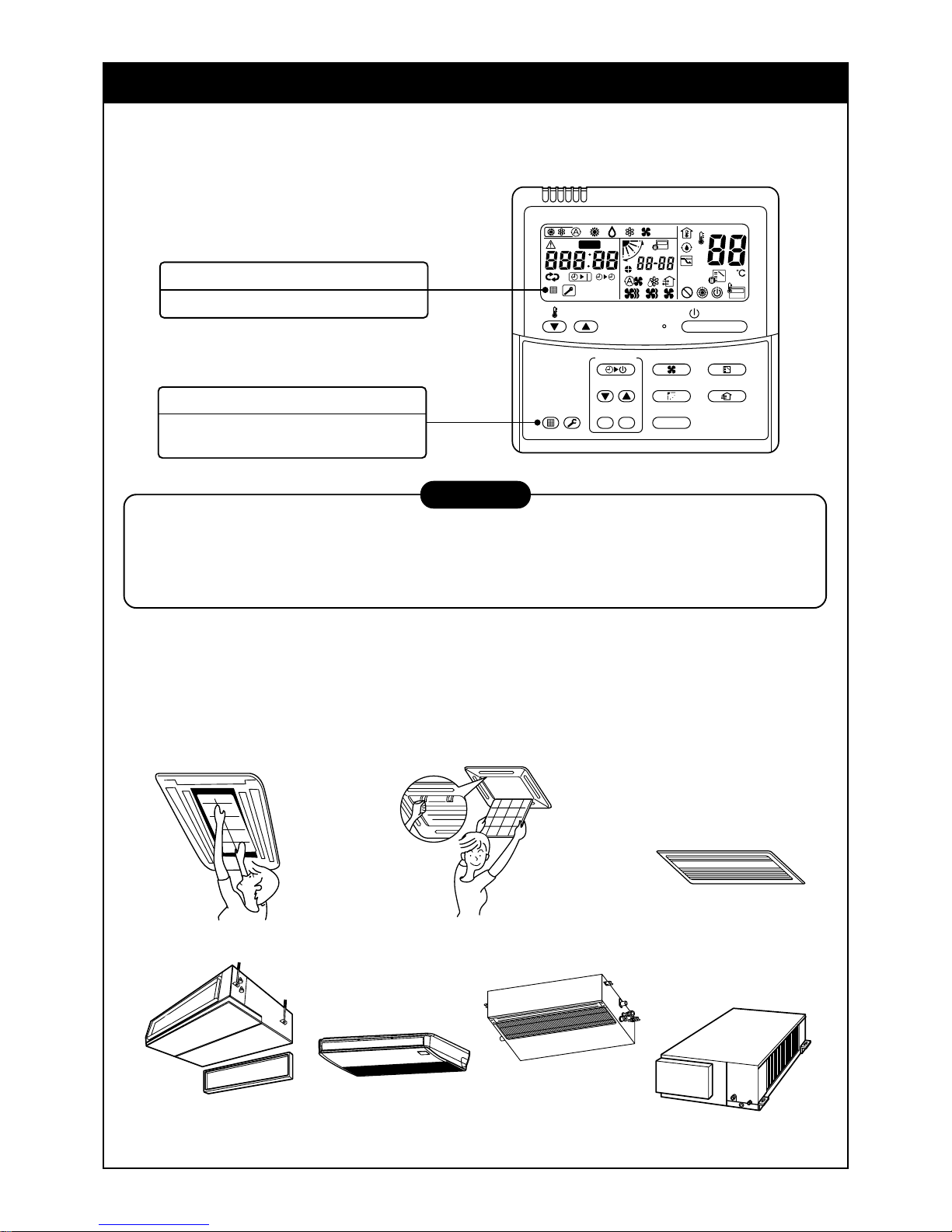
Cleaning of air filter
• When [FILTER] is displayed on the remote controller, it is time to check and if necessary clean the filter.
• Clogging of air filter decreases the cooling/heating effect.
WARNING
Be sure to turn off the main power supply prior to any maintenance.
• Please do not intend to do the daily maintenance and/or Air Filter cleaning by yourself.
Cleaning the air filter and other parts of the unit involves dangerous work in high places, so be sure to
have a qualified service person do it. Do not attempt it by yourself.
Daily maintenance
• For daily maintenance including Air Filter cleaning, please use qualified service personnel, particularly for the
following models -
4-way Air Discharge Cassette Type Concealed Duct Standard Type Under Ceiling Type
2-way Air Discharge Cassette T ype Slim Duct Type
1-way Air Discharge Cassette Type Concealed Duct High Static Pressure Type
ON / OFF
FAN
TEMP.
SWING/FIXTIME
MODE
VENT
UNITSET CL
FILTER
RESET
TEST
TIMER SET
CODE No.
UNIT No.
TEST
SETTING
DATA
SET
R.C. No.
H
FILTER display
Notifies the time to clean the air filter.
FILTER reset
Push the FILTER switch after cleaning.
“FILTER” display disappears.
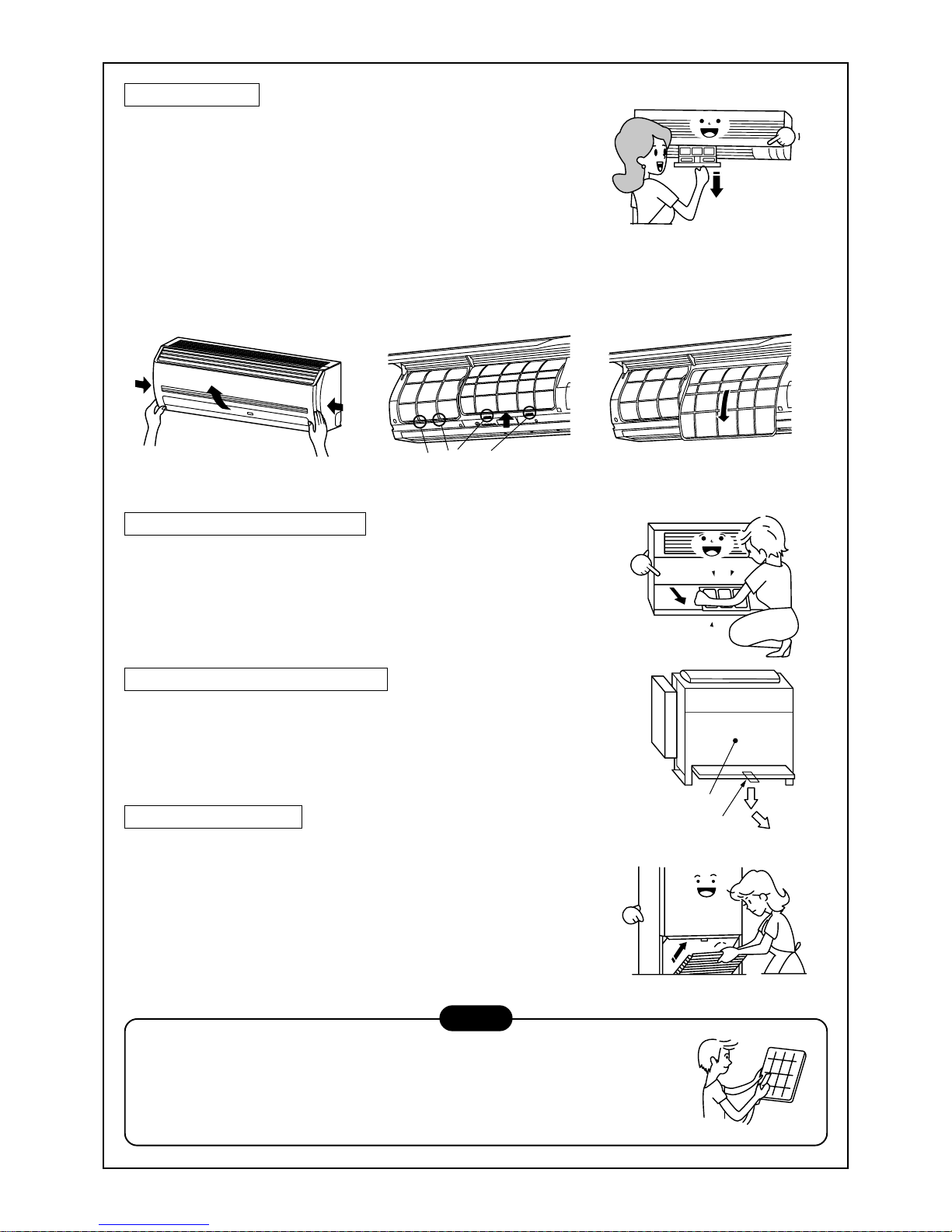
19
Push the air filter,
and pull it downward.
Front panel
(Lower)
Air filter knob
Filter holder
High Wall T ype
(Model : 1H series)
• Push the projection at the center of the air filter.
• Undo the clip on the air filter, pull the air filter downwards while
pushing it towards the main unit side.
(Model : 2H series)
• Open the air inlet grille.
Lift the air inlet grille up to the horizontal position.
• T ake hold of the left and right handles of the air filter and lift it up
slightly, then pull downwards to take it out from the filter holder.
Floor Standing Cabinet Type
• Gently push down on the upper part of the suction port, and then
pull towards you to remove it.
• T ake out the air filter inside of the suction port.
Floor Standing Concealed Type
• Push down hook of the air filter on the front panel (Lower side).
• Pull the air filter towards you to remove it.
Floor Standing Type
Removal / Attachment of air filter
• Pull the air filter towards you.
• T o attach the air filter, insert it into the main body and push it in.
NOTE
• When cleaning the air filter, use a small brush or cleaning device. If the air
filter is heavily stained, use a neutral detergent mix ed with warm water.
• After washing the filter, rinse it out thoroughly and place in the shade to
dry . Do not expose to direct sun light.
• Once the air filter has dried, place the air filter back into the unit.
20
Do not use.
Polishing
powder
Benzene
Thinner
Chemical
floor-cloth
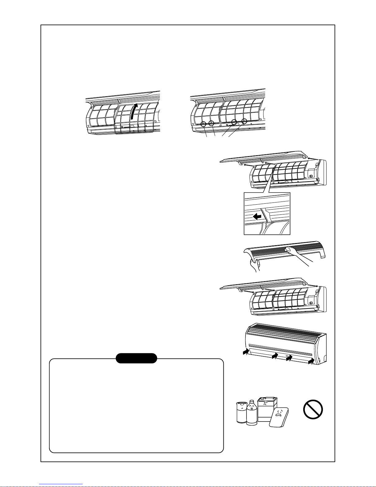
Filter holder
Re-installing the air filter
• Insert the the air filter back into the unit, ensuring that both sides of the filter are positioned correctly inside
of the plastic frame.
• Close the air inlet grille.
If the FILTER lamp on the indoor unit is displayed, press the FILTER button on the remote controller or the
TEMPORARY b utton on the indoor unit. This will turn the light off .
Cleaning the air inlet grille
1. Remove the air inlet grille.
Hold the two sides of the air inlet grille and open upwards.
Move the center arm to the left and remove the grille.
2. Wash the grille with water using a soft sponge or towel.
(Do not use metallic scrubbing brush or other hard brushes.)
• Use of such hard objects will cause scratches on the
surface of the grille, and the metal coating to peel off.
• If very dirty, clean the air inlet grille with a neutral detergent
for kitchen use, and rinse off with water.
3. Dry the inlet grille, ensuring no water is left.
4. Fit the left and right arms of the air inlet grille to the shafts on
the two sides of the air conditioner and push in completely.
Then push in the center arm.
5. Chec k that the center arm has been completely inserted and
then close the air inlet grille.
• Push the arrow locations (four) at the bottom of the air inlet
grille to check whether the grill is completely closed.
Cleaning of the main unit / remote controller
CAUTION
• Wipe them with a soft and dry cloth.
• A cloth dampened with cold water may be used on the indoor
unit if it is very dirty.
• Never use a damp cloth on the main unit and the remote
controller.
• Do not use or leave a chemically treated duster on the unit for
long periods of time, as it may damage or alter the colour of the
unit surface.
• Do not use benzine, thinner, polishing powder, or similar solvents for cleaning. These may cause the plastic surface to
crack or deform.
21
I will wipe soft
and dry cloth!
Use after drying
when it has not been
used for a long time!
Control
Gee, chilly
Clean, please.
Please close
Blows upward
Blows downward
Air flow adjustment
Cool and
dry air
Warm
air
If you do not plan to use the unit for more than 1 month
1. Operate the fan for 3 to 4 hours to dry the inside of the unit
• Operate “FAN” mode.
2. Stop the air conditioner and turn off the main power supply
or the circuit breaker .
Checks before operation
1. Check that the air filters are installed.
2. Check that the air outlet or inlet is not blocked.
3. Turn on the main power switch or the circuit breaker f or the
main power supply to the air conditioner .
NOTE
For Air conditioning system which is operated regularly, cleaning and maintenance of the indoor/outdoor
units are strongly recommended.
As a general rule, if an indoor unit is operated for about 8 hours daily, the indoor/outdoor units will need to
be cleaned at least once every 3 months. This cleaning and maintenance shall be carried out by a qualified person.
Failure to clean the indoor/outdoor units regularly will result in poor perf ormance, icing, water leakage and
even compressor failure.
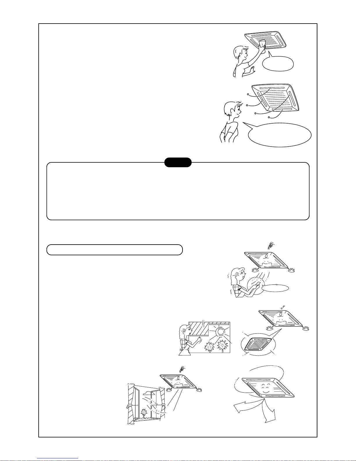
HINTS FOR ECONOMICAL OPERA TION
Maintain room temperature at comfortable level
Clean air filters
The clogged air filter impairs the performance of the air conditioner.
Never open doors and windows more than what is necessary
To keep the cool or warm air in the room, nev er open doors and
windows more than what is necessary .
Window curtains
In cooling, close the curtains to avoid direct sunlight.
In heating, close the curtains to keep the heat in.
Ensure uniform circulation of room air
Adjust the air flow direction so that the air
is evenly circulated throughout the room.
22
WARNING
Turn on the power supply
12 hours or more before
starting the air conditioner.
AIR CONDITIONER OPERATIONS AND PERFORMANCE
Check before operation
• Check whether earth wire is disconnected or out of place.
• Check that air filter is installed to the indoor unit.
Heating capacity (for Heat-pump model only)
• During heating operation the heat pump system operates by
absorbing the heat from the outside air and discharging it into the room.
Therefore if the outside temperature drops, the units heating capacity will decrease.
• When temperature of the outside air is low, it is recommended that you use other forms of heating in con-
junction with the air conditioner.
Defrost operation during heating operation (for Heat-pump model only)
• If the outdoor unit has a build up of frost during the heating operation, the operation mode changes automati-
cally to defrost mode to increase the heating effect (for approximately 2 to 10 minutes).
• During defrost operation, fans of the indoor and the outdoor units will stop.
Protection for 3 minutes
• The outdoor unit will not operate for approximately 3 minutes after the air conditioner has been immediately
restarted after being stop, or the power supply has been turned on. This is to protect the system.
Main power failure
• If a power failure occurs during operation, all operations stop.
• When restarting the unit, push the ON/OFF button again.
Fan rotation of stopped unit
• When other indoor units within the same system are in operation, the fan on the indoor units that are on
“stand-by” will rotate to protect the machine once approximately 1 hour for several minutes.
Protective device (High pressure switch)
The high pressure switch operates the unit automatically when excessive load is applied to the air conditioner.
If the protective device operates, the operation lamp will stay but the operation will stop.
When the protective device operates, check characters “
” on the remote controller display.
The protective device may operate in the following cases.
In Cooling operation
• When suction or discharge port of the outdoor unit is closed.
• When strong winds blow continuously against the discharge port of the outdoor unit.
In Heating operation (For Heat-pump model only)
• When excessive dirt or dust is adhered to the air filter of the indoor unit.
• When the discharge port of the indoor unit is blocked.
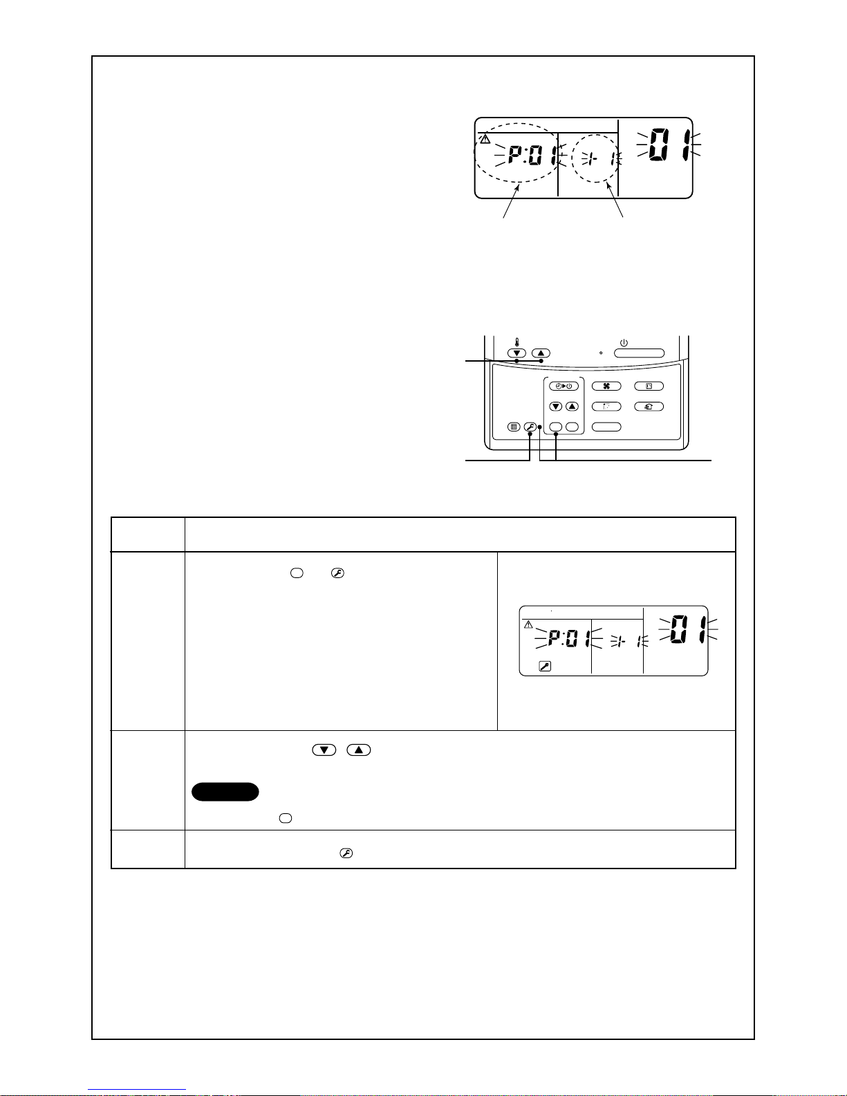
Cooling/heating operation of MiNi-SMMS air conditioner
In MiNi-SMMS air conditioner, each indoor unit can be individually controlled. However, cooling operation and
heating operation cannot be performed concurrently for the indoor units, which are connected to the same
outdoor unit.
When cooling operation and heating operation are performed concurrently, the indoor unit which is performing
cooling operation stops, and the “
” on the unit display will be lit. The indoor unit that is in heating mode will
continue operation.
If the manager has fixed the setting to COOL or HEAT, no other operation can be performed.
When another operation other than the set up one is performed, the “
” light is displayed on the display part
of the indoor unit.
Characteristics of heating operation (For Heat-pump model only)
• Hot air will not be blown out immediately from the indoor unit. It will take between 3 to 5 minutes (depending
on temperature conditions of the room and the outside) before the indoor heat exchanger warms up sufficiently, to allow hot air to be blown.
• During operation, the outdoor unit may stop if the outside temperature becomes to high.
• When other indoor units are in heating operation, the fan operation of the indoor unit on fan only operation
may be stopped temporarily to prevent hot air from being blown out.
23
Air conditioner operating conditions
For the specified performance, operate the air conditioner under the following temperature conditions:
If air conditioner is used outside of the above conditions the units, safety protection devices may operate.
RE-INSTALLATION
DANGER
If the unit position is to be changed and re-located to a new position ask your local dealer or installation specialist. Do not attempt to move the air conditioner yourself, as incorrect installation may
cause electric shock or fire.
Do not install the air conditioner in the following places
• Do not install the air conditioner in any place within 1 m from a TV, stereo, or radio set. If the unit is installed
in such places, noise transmitted from the air conditioner may effect the operation of these appliances.
• Do not install the air conditioner near a high frequency appliance (sewing machine or massager for business
use, etc.), as the air conditioner may malfunction.
• Do not install the air conditioner in a humid or oily place, or in a place where steam, soot, or corrosive gas
may be generated.
• Do not install the air conditioner in a salty place such as a seaside area.
• Do not install the air conditioner in a place where a great deal of machine oil is used.
• Do not install the air conditioner in a place where it is usually exposed to strong winds such as in a seaside
area or on the roof / upper floor of a building.
• Do not install the air conditioner in a place where sulfureous gas may be generated such as in a spa.
• Do not install the air conditioner in a vessel or mobile crane.
Be careful with noise or vibrations
• Do not install the air conditioner in a place where the noise or the hot air created by the outdoor unit will
come into contact with your neighbours.
• Install the air conditioner on a solid and stable foundation as this will reduce the transmission of noise and
vibration that is produced from the outdoor unit.
• If one indoor unit is operating, some sound may be audible from other indoor units that are connected within
the same system (even when not in operation).
Cooling operation
Heating operation
Outdoor temperature : –5°C to 43°C (Dry-bulb temp.)
Room temperature : 21°C to 32°C (Dry-bulb temp.), 15°C to 24°C (Wet-bulb temp.)
CAUTION
Room relative humidity – less than 80 %. If the air conditioner operates
in excess of this figure, the surface of the air conditioner may cause dewing.
Outdoor temperature : –15°C to 15.5°C (Wet-bulb temp.)
Room temperature : 15°C to 28°C (Dry-bulb temp.)
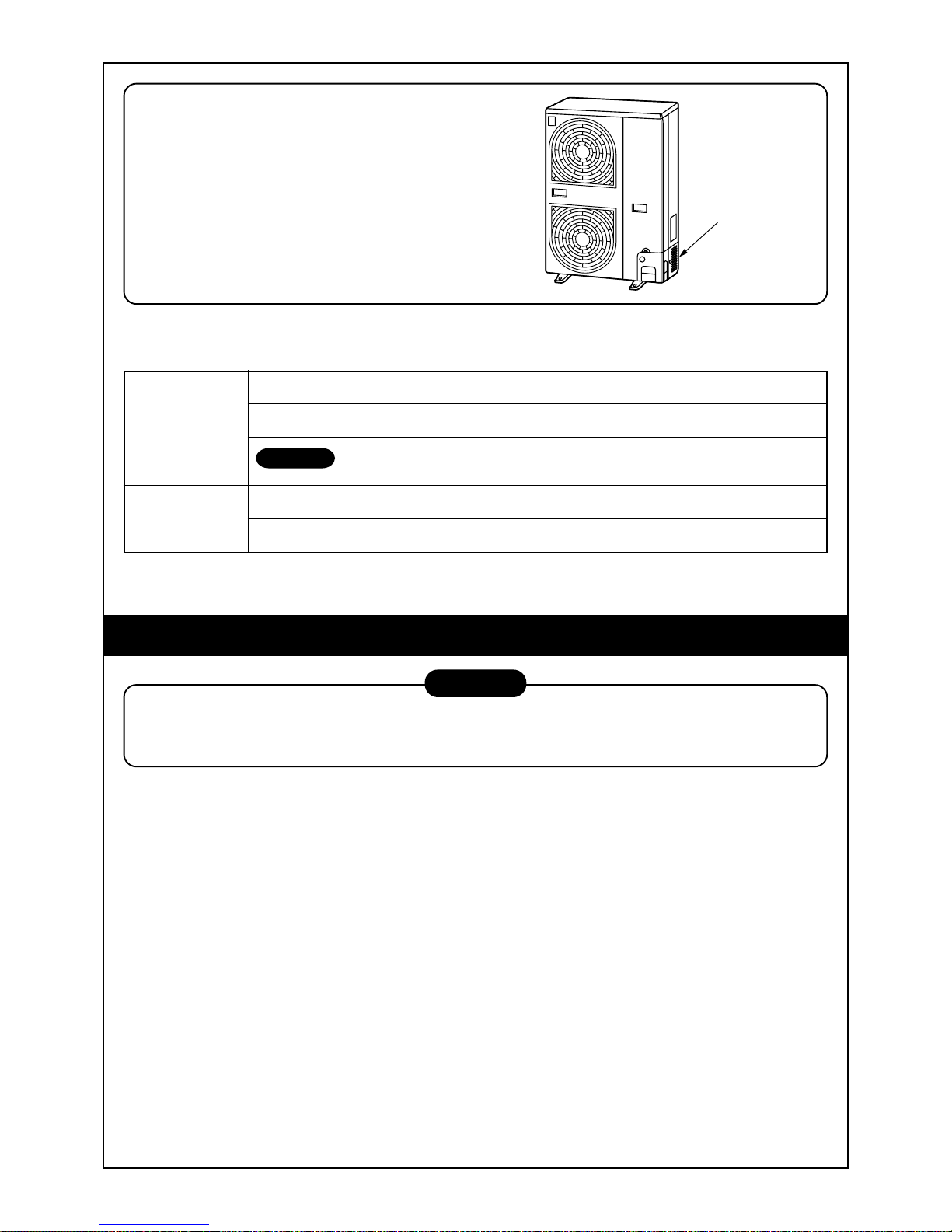
The slot provided at side surface of the outdoor
unit is an air intake for cooling the electrical parts.
If the air intake would be clogged, a trouble is
caused on the electrical parts.
Therefore never close the air intake or do not
place any obstacle near the air intake.
Slot for air intake
24
Silent
It’s strange.
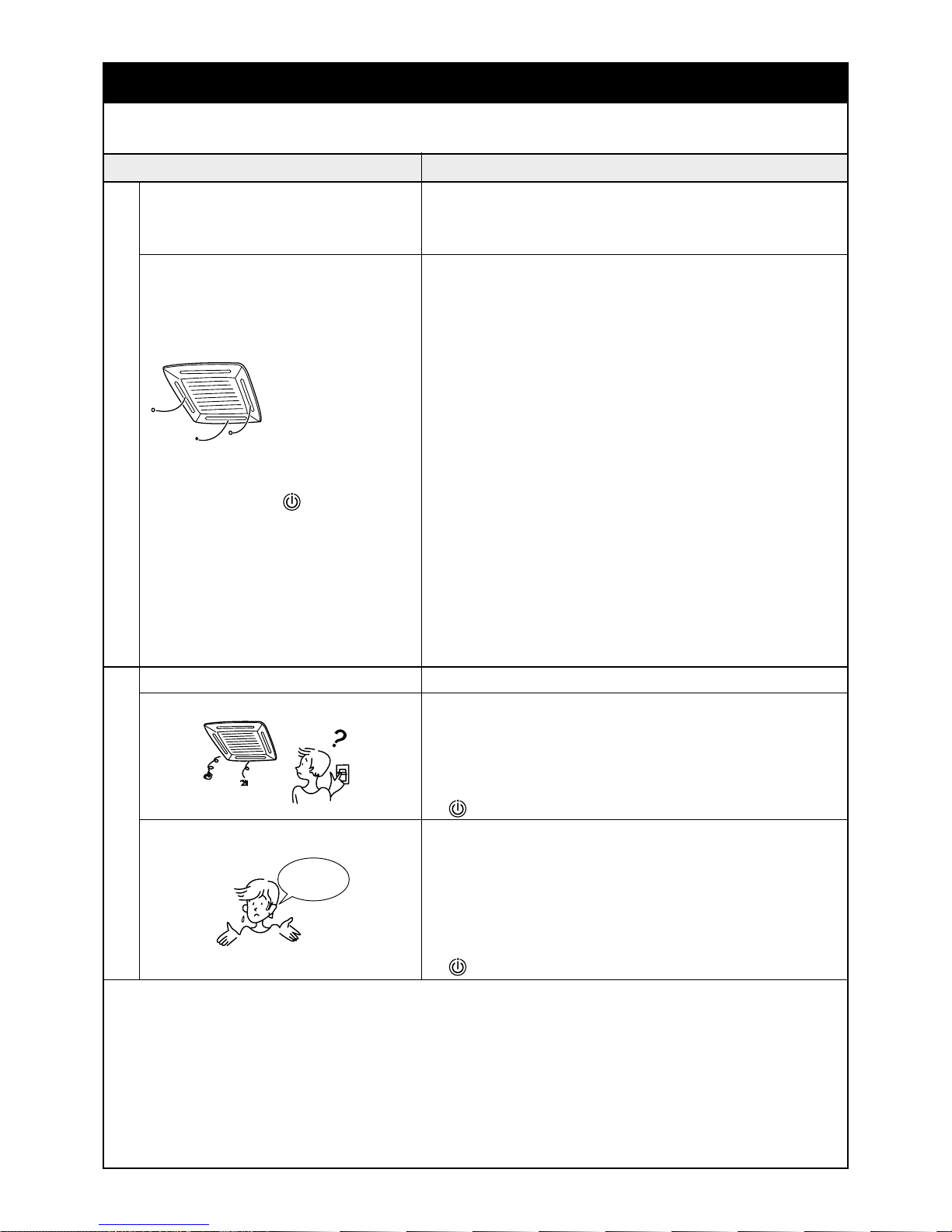
WHEN THE FOLLO WING SYMPTOMS ARE FOUND
Check the points described below before contacting your local service repair center.
Check again.
It is not a failure.
Cause
• Fan of the outdoor unit stops automatically and performs defrost
operation.
• Solenoid valve works when defrost operation starts or finishes.
• When the unit is in operation,a sound such as the movement of
water from one area to another may be heard. This sound may
become larger after a period of 2 to 3 minutes once the unit has
begun operation. This is not a cause for concern, but is the movement of the refrigerant or the draining sound of the dehumidifier.
• When the air conditioner system is operating, the stopping indoor
unit in the same system needs temporary flow of refrigerant to
prevent the stay of oil or refrigerant.
Therefore, refrigerant flow sound “shaa/cyu” may be heard, or white
vapor may come out when other indoor unit heating, or cool air
may come out when other indoor unit cooling.
• This sound is generated when the heat exchanger, etc. expands
and contracts slightly due to the change of temperature.
• Various odurs such as those from a carpet, clothes, cigarette, or
cosmetics will adhere to the air conditioner.
• When cooling operation cannot be performed because another
indoor unit performs heating operation.
• When the manager of the air conditioner has fixed the operation to
either COOL or HEAT, but a request or demand contrary to the
setup operation is requested.
• When the fan operation is stopped to prevent the discharge of hot
air.
• Sound is generated when the expansion valve operates when the
power supply has been turned on.
• Is the timer “ON” or “OFF”?
• Is there a power failure to the unit?
• Has the power supply been turned off?
• Has the power fuse or breaker blown?
• Has the protective device operated? (The operation lamp goes on.)
• Is the timer “ON”? (The operation lamp goes on.)
• Are COOL and HEAT selected simultaneously?
(“
” indication is lit on the display column of the remote controller.)
• Is the suction port or discharge port of the outdoor unit obstructed?
• Are there any doors or windows open?
• Is the air filter clogged with dust?
• Is the discharge louver of the indoor unit set at appropriate position?
• Is the air selection set to “LOW” or “MED” and is the operation
mode set to “FAN”?
• Is the setup temp. the appropriate temperature?
• Are COOL and HEAT selected simultaneously?
(“ ” indication is lit on the display column of the remote controller.)
Symptom
Outdoor unit • White misty cold air or
water is blown out.
• Sometimes, the noise
“Pushu !” is heard.
Indoor unit •“Swish” sound is
sometimes heard.
• A stopping indoor unit
in the same operating
air conditioner system
emitted sound, white
vapor or cool air.
• Slight “Pishi!” sound is
heard.
• Discharge air smells.
•“
” indication is lit.
• When power of the air
conditioner is turned
on, “Ticktock” sound is
heard.
Operates or stops automatically.
Does not operate.
Air is not cooled or warmed sufficiently.
When the following symptoms are found, stop the operation immediately, tur n off the power supply, and contact the dealer from where you have purchased the air conditioner.
• Activation of the power supply causing the unit to operate in an unstable fashion
(power on, power off , power on, power off etc).
• The main power fuse often blows out, or circuit breaker is often activated.
• Foreign matters or water have entered the unit by mistake.
• When the unit fails to operate after the protective device (circuit breaker) has been removed.
Not recommended.
• Other unexplained symptoms or unit abnormalities, that cannot be explained.
25
3
2
1
ON / OFF
FAN
TEMP.
SWING/FIXTIME
MODE
VENT
UNITSET CL
FILTER
RESET
TEST
TIMER SET
CODE No.
UNIT No.
R.C. No.
Confirmation and check
When a error has occurred in the air conditioner, the
check code and the indoor unit No. will appear on
the display part of the remote controller.
The check code is only displayed during while the
unit is operating.
If the display disappears, operate the air conditioner
according to the following “Confirmation of error
history” for confirmation.
Confirmation of error history
When a error has occurred on the air conditioner,
the error history can be confirmed with the following
procedure. (up to 4 errors can be stored in the
memory of the remote controller)
The history can be confirmed from both operating
status and stop status.
Procedure
1
2
3
Description
When pushing the
SET
and
TEST
buttons at the same time
for 4 seconds or more, the following display will appear.
If [Service check] is displayed, the mode enters into the
error history mode.
• [01 : Order of error history] is displayed in CODE No.
window.
• [Check code] is displayed in CHECK window.
• [Indoor unit address in which the error has occurred]
is displayed in UNIT No.
For every push of the [ , ] button, the error history stored in memory is displayed in order.
The numbers in CODE No. indicate CODE No. [01] (latest) → [04] (oldest).
CAUTION
Do not push the
CL
button because all the error history of the indoor unit will be deleted.
After confirmation, push the
TEST
button to return to the normal display.
1. Check the error codes according to the above procedure.
2. Ask an authorized dealer or qualified service (maintenance) professional to repair or maintain the air conditioner.
3. More details of the service codes are explained in the Service Manual.
Check code
Indoor unit No. in which
an error occurred
CODE No.
UNIT No.
R.C. No.
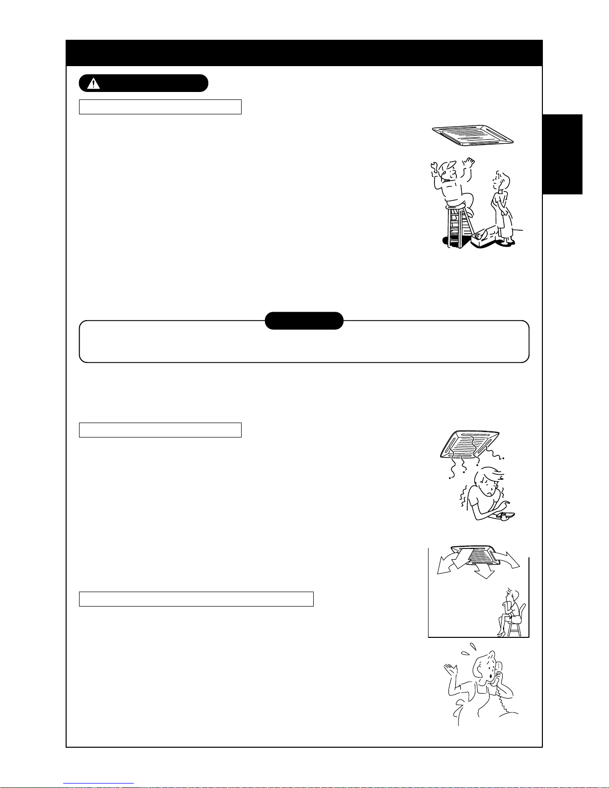
26
MESURES DE SECURITE
AVERTISSEMENT
Avertissement sur le montage
Confiez les travaux de montage au revendeur ou à un atelier
spécialisé.
Pour effectuer les travaux de montage il est indispensable d’avoir des
connaissances techniques approfondies.
N’essayez pas de le monter vous-mêmes. Un montage incomplet risque de
provoquer une électrocution, des b lessures , des fuites d’eau ou un incendie .
Vérifiez si les produits vendus séparément sont ceux que nous
avons indiqués.
Vérifiez si les produits vendus séparément sont ceux que nous av ons indiqués .
Autrement vous pourriez provoquer une électrocution, des blessures, des
fuites d’eau ou un incendie. Pour les travaux de montage adressez-vous à un
technicien spécialisé.
Si vous montez l’unité dans une petite pièce, prenez des mesures
afin que les fuites éventuelles de réfrigérant ne dépassent pas la
concentration critique.
PRUDENCE
Dans ce but, effectuez les travaux de montage après avoir demandé son avis à votre revendeur.
Si le réfrigérant fuit et dépasse la concentration critique, l’oxygène risque de venir à manquer.
Contrôlez si les travaux de mise à la terre sont effectués correctement
La mise à la terre est nécessaire. Une mise à la terre incomplète risque de provoquer une électrocution.
(Pour les détails , respectez scrupuleusement la réglementation locale de chaque pays).
Avertissement sur l’utilisation
Evitez d’exposer directement à l’air froid pendant longtemps une
quelconque partie de votre corps et de trop vous refroidir.
Cela pourrait nuire à votre condition ph ysique et à votre santé.
N’introduisez jamais ni barre ni doigt dans la bouche d’aspiration ou
dans la bouche de soufflage.
Le ventilateur à l’intérieur de l’unité tourne très vite et pourrait vous blesser.
Si vous sentez une odeur suspecte (odeur de brûlé, etc..) arrêtez le
fonctionnement, coupez l’alimentation électrique et adressez-vous
au revendeur du climatiseur.
Si vous laissez le climatiseur f onctionner en mauvais état vous pourriez
provoquer un incendie, une électrocution ou un autre prob lème .
Avertissement sur la manutention/réparation
Ne modifiez jamais le climatiseur.
Vous risqueriez de provoquer un incendie ou une électrocution.
Pour les réparations, contactez le revendeur du climatiseur.
Une réparation incomplète risque de provoquer une électrocution, des
blessures, des fuites d’eau ou un incendie.
Pour déplacer ou réinstaller le climatiseur, adressez-vous au
revendeur du climatiseur ou à un technicien spécialisé.
Un montage incomplet risque de provoquer une électrocution, des blessures,
des fuites d’eau ou un incendie.
FRANCAIS
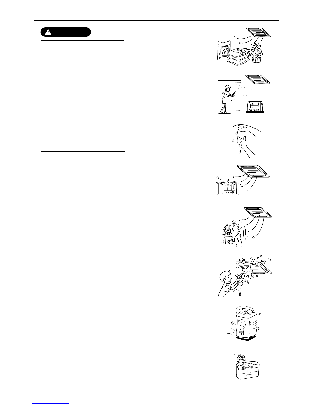
27
PRUDENCE
Prudence pendant le montage
Vérifiez si les tuyaux d’évacuation sont montés afin d’évacuer
correctement l’eau d’évacuation.
Si la tuyauterie est incomplète, les fuites d’eau risquent de mouiller les
meubles.
Vérifiez si le disjoncteur est branché.
En cas de besoin installez-en un. Si vous ne le faites pas vous pourriez
vous électrocuter.
Vérifiez si le climatiseur est monté loin de tout risque de fuite de
gaz.
Les fuites et l’accumulation de gaz autour de l’appareil risquent de
provoquer un incendie.
Vérifiez si l’unité extérieure est fixée sur son socle.
Si elle n’est pas solidement fixée sur son socle elle peut provoquer un
accident, par exemple en tombant.
Vérifiez la méthode de fixation
Ne nettoyez pas le climatiseur avec de l’eau.
Vous risqueriez de vous électrocuter.
Ne placez pas d’appareil de chauffage directement dans le flux
d’air du climatiseur.
Vous risqueriez de nuire à la combustion du combustible de cet appareil.
Aérez correctement la pièce lorsque vous utilisez le climatiseur
en même temps qu’un appareil de chauffage.
Si l’aération n’est pas bonne, l’oxygène risque de manquer.
Après un certain temps, vérifiez si la plaque de montage, etc…
n’est pas endommagée.
Si vous ne la changez pas lorsqu’elle est endommagée, l’appareil risque de
tomber et de blesser quelqu’un, etc..
Ne placez ni plantes ni animaux directement dans le flux d’air
du climatiseur.
Vous risqueriez de nuire à ces animaux et à ces plantes.
Ne laissez pas de produits en bombe à proximité du climatiseur et
ne pulvérisez pas de produit directement sur le climatiseur.
Vous risqueriez de provoquer un incendie.
Ne posez aucune récipient plein d’eau, comme des vases, sur
l’appareil.
En pénétrant dans l’unité détériore l’isolation électrique et risque de
provoquer une électrocution.
Ne manipulez pas les interrupteurs avec les mains humides.
Vous risqueriez de vous électrocuter.
N’utilisez pas le climatiseur pour entreposer des aliments, des
plantes, des animaux, des appareils de précision et des œuvres
d’art.
Il pourrait les endommager .

28
Evacuation à 2 voies/évacuation à 3 voies
Vous pouvez choisir l’évacuation à 2 ou à
3 voies en fonction de la forme et de
l’aménagement de la pièce.
Pour les détails, contactez le revendeur de
votre climatiseur.
Refoulement de l’air/
Volet de refoulement de l’air
Choisissez la direction du soufflage de
l’air pour le refroidissement ou le chauffage.
Vis de terre
Fait partie des pièces du
boîtier électrique.
Grille d’aspiration de l’air
L’air de la pièce est aspiré par cet orifice.
Filtre à air
Elimine la poussière et la saleté.
(Un filtre à air est fourni sur la
grille d’aspiration de l’air).
Attache
L’attache permet de fermer/
ouvrir la grille d’Aspiration de l’air
Vis de terre
Fait partie des pièces du
boîtier électrique.
Refoulement de l’air/
Volet de refoulement de l’air
Choisissez la direction du soufflage de
l’air pour le refroidissement ou le chauffage.
Filtre à air
Elimine la poussière et la saleté.
(Un filtre à air est fourni sur la
grille d’aspiration de l’air).
Attache
L’attache permet de fermer/
ouvrir la grille d’Aspiration de l’air
Grille d’aspiration de l’air
L’air de la pièce est aspiré par cet orifice.
Aspiration d’air
L’air de la pièce est
aspiré par cet orifice.
Filtre à air
Elimine la poussière et la saleté.
(Un filtre à air est prévu dans le panneau du centre)
Vis de terre
Fait partie des pièces du boîtier électrique.
Panneau central
Refoulement de l’air/
Volet de refoulement de l’air
Choisissez la direction du soufflage de
l’air pour le refroidissement ou le chauffage.
Unité intérieure
[Type cassette à 4 voies de refoulement]
De MMU-AP0091H, AP0121H, AP0151H, AP0181H, AP0241H,
MMU-AP0271H, AP0301H, AP0361H, AP0481H, AP0561H
[Type cassette à 2 voies de refoulement]
Aspiration de l’air
Il y en a sur la façade,
dans le dos et sur les
côtés droit et gauche.
Piétement de fixation
Refoulement de l’air (évacuation)
L’air chaud est évacué pendant le refroidissement.
L’air froid est refoulé pendant le chauffage.
Orifice de l’alimentation
électrique
Orifice de raccordement
du tuyau de réfrigérant
Robinet de raccordement
fourni à l’intérieur.
Unité extérieure
De MMU-AP0071MH, AP0091MH, AP0121MH, AP0151MH, AP0181MH
NOM DE CHAQUE PIÈCE
Pièces vendues séparément
Télécommande filaire
RBC-AMT31E
Télécommande filaire simple
RBC-AS21E2
Kit de télécommandes sans fil
TCB-AX21E2 RBC-AX22CE2 RBC-AX21U(W)-E2
ON / OFF
FAN
TEMP.
SWING/FIXTIME
MODE
VENT
UNITSET CL
FILTER
RESET
TEST
TIMER SET
CODE No.
UNIT No.
TEST
SETTING
DATA
SET
R.C. No.
H
˚C
TEST
SETTING

29
Minuterie hebdomadaire
RBC-EXW21E2
Télécommande centrale
TCB-SC642TLE2
WEEKLY TIMER
ERROR
SuMoTuWeTh FrSa
PROGRAM1
PROGRAM2
PROGRAM3
SELECT ZONE
CL
SET
GROUP
CODE
No.
UNIT No.
No.
R.C.
TEST
ZONE
ALL
ZONE
GROUP
SETTING
1234
SET DATA
Vis de terre
Fait partie des pièces du boîtier
électrique.
Refoulement de l’air/
Volet de refoulement de l’air
Choisissez la direction du soufflage de l’air
pour le refroidissement ou le chauffage.
Grille d’aspiration de l’air
L’air de la pièce est aspiré
par cet orifice.
Filtre à air
Elimine la poussière et la saleté.
(Un filtre à air est fourni sur la grille d’aspiration de l’air).
[Type cassette à 1 voies de refoulement]
De MMU-AP0071YH à AP0121YH
De MMU-AP0152SH, AP0182SH, AP0242SH
Touche
Bouton d’ouverture/
fermeture de la bouche
d’aspiration
Refoulement de l’air/
Volet de refoulement de l’air
Modifie le sens de refoulement d’air
en fonction du mode chaud/froid.
Filtre à air
Elimine la poussière et la saleté.
(Prévu sur la bouche d’aspiration)
Port d’aspiration
Aspire l’air de la pièce par ici.
Filtre à air
Elimine la poussière et la saleté.
(Prévu sur la bouche d’aspiration)
Vis de terre
Fait partie des pièces du boîtier électrique.
[Type standard à conduit dissimulé]
[Conduit dissimulé type à pression statique élevée]
Filtre à air
Elimine la poussière et la saleté.
(Un filtre à air est fourni sur
la grille d’aspiration de l’air)
Bride du refoulement de l’air
Le conduit de refoulement
est raccordé
Vis de terre
Les vis de terre font partie des
pièces du boîtier électrique.
Aspiration de l’air
L’air de la pièce est aspiré
par cet orifice.
Aspiration de l’air
Le conduit d’aspiration
est raccordé.
Refoulement de l’air
Le conduit d’évacuation
est raccordé.
Vis de terre
Les vis de terre font
partie des pièces du
boîtier électrique.
Bac d’évacuation
[Type Conduit Mince]
Aspiration de l’air
Le conduit d’aspiration
est raccordé.
Filtre à air
(Sur certains modèles
de certaines séries
aucun filtre à air n’est fourni)
Vis de terre
Fait partie des pièces
du boîtier électrique.
Refoulement de l’air
Le conduit d’évacuation
est raccordé.

30
[Type mural haut]
De MMK-AP0071H à AP0241H
De MMK-AP0072H à AP0122H
Grille d’aspiration de l’air
L’air de la pièce est aspiré par là.
Vis de terre
Les vis de terre font partie des pièces du
boîtier électrique.
Filtre à air
Elimine la poussière et la saleté.
(Un filtre à air est fourni sur la grille
d’aspiration de l’air)
Refoulement de l’air/
Volet de refoulement de l’air
Modifie le sens de refoulement d’air en
fonction du mode chaud/froid.
[Type dans faux-plafond]
Vis de terre
Les vis de terre font partie des pièces du
boîtier électrique.
Touche
Bouton d’ouverture/fermeture
de la bouche d’aspiration
Filtre à air
Elimine la poussière et la saleté.
(Prévu sur la bouche d’aspiration)
Refoulement de l’air/Volet de refoulement de l’air
Modifie le sens de refoulement d’air en fonction du mode chaud/froid.
Bouche d’aspiration de l’air
L’air de la pièce est aspiré par cet orifice.
[Type armoire à châssis
vertical posé au sol]
[Type à châssis vertical
dissimulé au sol]
[Type à châssis vertical posé au sol]
Refoulement de l’air/
Volet de refoulement de l’air
Change la direction de l’air en fonction de
l’horaire de chauffage ou de refroidissement.
Vis de terre
Fait partie des pièces du boîtier électrique.
Bouche d’aspiration de l’air
Aspire l’air de la pièce par ici.
Filtre à air
Elimine la saleté et la poussière.
(Il est prévu dans la bouche d’aspiration).
Bouche de refoulement de l’air
Bac d’évacuation
(avec filtre d’évacuation)
Cet accessoire est monté sur place.
Filtre à air
Elimine la saleté et la poussière.
(Il est prévu dans la bouche d’aspiration).
Bouche d’aspiration de l’air
Aspire l’air de la pièce par ici.
Vis de terre
Fait partie des pièces du boîtier électrique.
Façade (bas)
Volet vertical
L’air peut être évacué directement vers la
droite/la gauche à des moments prévus.
Support de fixation métallique
Volet horizontal/
bouche de refoulement de l’air
Change la direction de l’air en fonction
de l’horaire de chauffage ou de refroidissement.
Vis de terre
Fait partie des pièces du boîtier électrique.
Bouche d’aspiration de l’air
Aspire l’air de la pièce par ici.
Filtre à air
Elimine la saleté et la poussière.
Bac d’évacuation
L’eau qui s’accumule dans le bac
d’évacuation s’écoule ensuite dans le
tuyau d’évacuation.
Support de fixation métallique
(droit et gauche)

31
NOM DES PIECES DE LA TELECOMMANDE
Section
d’affichage
Section de
fonctionnement
ON / OFF
FAN
TEMP .
SWING/FIXTIME
MODE
VENT
UNITSET CL
FILTER
RESET
TEST
TIMER SET
CODE No.
UNIT No.
TEST
SETTING
DATA
SET
R.C. No.
H
2
15
5
78 9
3
1
4
6
10
11
13
16
12
14
17
CODE No.
UNIT No.
TEST
SETTING
DATA
SET
R.C. No.
H
Section d’affichage
Toutes les rubriques d’affichage sont représentées sur la figure
de droite pour l’explication.
Seules les rubriques sélectionnées sont affichées lors du
fonctionnement normal.
• Lors de la première activation du disjoncteur, [SET DATA]
(PARAMETRAGE) clignote dans l’afficheur de la télécommande. Alors
que cet affichage clignote, le modèle est vérifié automatiquement. Par
conséquent, attendez que [SET DATA] (PARAMETRAGE) disparaisse de
l’afficheur avant d’utiliser la télécommande.
1
Affichage de SET DATA (PARAMETRAGE)
Apparaît durant le réglage de la minuterie.
2
Affichage du mode de fonctionnement
Le mode de fonctionnement sélectionné apparaît.
3
Affichage de CHECK (VERIFICATION)
Apparaît lors du fonctionnement du dispositif de
protection ou en cas de panne.
4
Affichage de l’heure de la minuterie
L’heure réglée par la minuterie apparaît.
(En cas de panne, le code de vérification
apparaît.)
5
Affichage du réglage de SETIN
(FONCTIONNEMENT) par minuterie
Lorsque vous appuyez sur la touche SETIN
(FONCTIONNEMENT) par minuterie, sélectionnez
l’affichage dans l’ordre [OFF].
[OFF]
→ [OFF] Répétition
DESACTIVATION par minuterie →
[ON]
→ Pas d’affichage
6
Affichage du filtre
Si “FILTER ” s’affiche, nettoyez le filtre à air.
7
Affichage de TEST RUN
(ESSAI DE FONCTIONNEMENT)
Apparaît durant un essai de fonctionnement.
8
Affiche la position du volet
(uniquement pour le type à cassette de
refoulement à 4 voies et pour le type en
faux-plafond)
Affiche la position du volet.
9
Affichage de SWING (OSCILLATION)
Apparaît durant le déplacement haut/bas du volet.
10
Affichage de la température définie
La température définie sélectionnée apparaît.
11
Affichage du capteur de la
télécommande
Apparaît lors du fonctionnement du capteur de la
télécommande.
12
Affichage de PRE-HEAT
(uniquement pour le modèle à thermopompe)
Apparaît lorsque le chauffage commence ou lors du
dégivrage. Alors que l’indication s’affiche, le
ventilateur de l’unité intérieure s’arrête ou le mode de
ventilation passe à LOW (FAIBLE).
13
Affiche l’état prêt à fonctionner.
S’affiche lorsque le refroidissement ou le chauffage
est impossible parce que la température extérieure
sort de la plage de fonctionnement.
14
Affichage d’absence de fonction
Apparaît en cas d’absence de fonction même si vous
appuyez sur la touche.
15
Affichage du mode de ventilation
Le mode de ventilation sélectionné apparaît.
AUTO
(AUT OMATIQUE) HIGH (ELEVE)
MED . (MO YEN) LOW (FAIBLE)
Sur les modèles à pression statique élevée et conduit
dissimulé, seul [HIGH] s’affiche pour la vitesse de
l’air.
16
Affichage du contrôle de sélection du mode
S’affiche en appuyant sur la touche “Sélection du
mode de fonctionnement
” tandis que le mode de
fonctionnement est défini comme chauffage ou
refroidissement par le gestionnaire de système du
climatiseur.
17
Affichage du contrôle central
S’affiche lorsque la commande à distance est utilisée
en même temps que la commande à distance du
contrôle central, etc..
Si la commande à distance est interdite du côté du
contrôle central,
clignote lorsque vous appuyez
sur les touches
ON / OFF
,
MODE
, / et le
changement est refusé.
(Les possibilités de configuration disponibles pour la
commande à distance varient en fonction du mode du
contrôle central. Pour en savoir davantage, consultez
le Manuel de l’utilisateur de la commande à distance
du contrôle central).

32
Section de fonctionnement
Appuyez sur chaque touche pour sélectionner le mode de fonctionnement désiré.
La télécommande ne peut faire f onctionner que 8 unités intérieures.
• Les détails du mode de fonctionnement doivent être réglés une fois pour toutes ; les mêmes états sont
utilisés en appuyant sur la touche
ON / OFF
.
1
Touche de sélection du volume d’air
Sélectionne le volume d’air désiré.
Ne peut pas faire fonctionner les modèles à
pression statique élevée et conduit dissimulé.
2
Touche de réglage de la minuterie
Utilisez la touche TIMER SET (REGLAGE
MINUTERIE) pour régler la minuterie.
3
Touche de vérification
La touche CHECK (VERIFICATION) sert à
vérifier le fonctionnement. N’utilisez pas cette
touche durant le fonctionnement normal.
4
Touche
VENT
La touche
VENT
est utilisé en cas de connexion
d’un ventilateur, en vente dans le commerce.
• Si
s’affiche sur la télécommande lorsque
vous appuyez sur la touche
VENT
, cela signifie
qu’aucun ventilateur n’est connecté.
5
Touche de remise à zéro du filtre
Remet à zéro (efface) l’affichage “FILTER ”.
6
Direction du soufflage et oscillation
UNIT
: Si vous faites fonctionner plusieurs
unités intérieures avec ne seule
télécommande, sélectionnez les unités
après avoir réglé la direction de l’air.
SWING/FIX
: Configurez l’oscillation automatique et
l’angle du volet,
• Cette fonction n’est prévue ni sur le type
standard à conduit dissimulé, ni sur le type à
pression statique élevée, ni sur le type à
armoire à châssis vertical, ni sur le type à
conduit dissimulé au sol et type conduit mince.
7
Témoin de fonctionnement
Le témoin est allumé durant le fonctionnement.
Le témoin est éteint durant l’arrêt.
Il clignote lors de l’utilisation du dispositif de
protection ou en cas d’anomalie.
8
Touche
ON / OFF
Lorsque vous appuyez sur la touche, le
fonctionnement commence ; il s’arrête si vous
appuyez à nouveau sur la touche.
Lorsque le fonctionnement s’arrête, le témoin de
fonctionnement et toutes les indications
disparaissent.
9
Touche de sélection du mode de
fonctionnement
Sélectionne le mode de fonctionnement.
10
Touche de réglage de la température
Règle la température ambiante requise.
Réglez la température définie requise en
appuyant sur
ou .
OPTION :
Capteur de télécommande
Le capteur de TEMP. de l’unité intérieure mesure
habituellement la température.
La température entourant la télécommande peut
elle aussi être mesurée.
Pour les détails , contactez le revendeur chez lequel
vous av ez acheté le climatiseur.
• Si vous faites fonctionner plusieurs unités
intérieures avec une seule télécommande, vous
pouvez configurez le contrôle de groupe.
1
7
3
5
2
8
9
6
4
10
ON / OFF
FAN
TEMP.
SWING/FIXTIME
MODE
VENT
UNITSET CL
FIL TER
RESET
TEST
TIMER SET
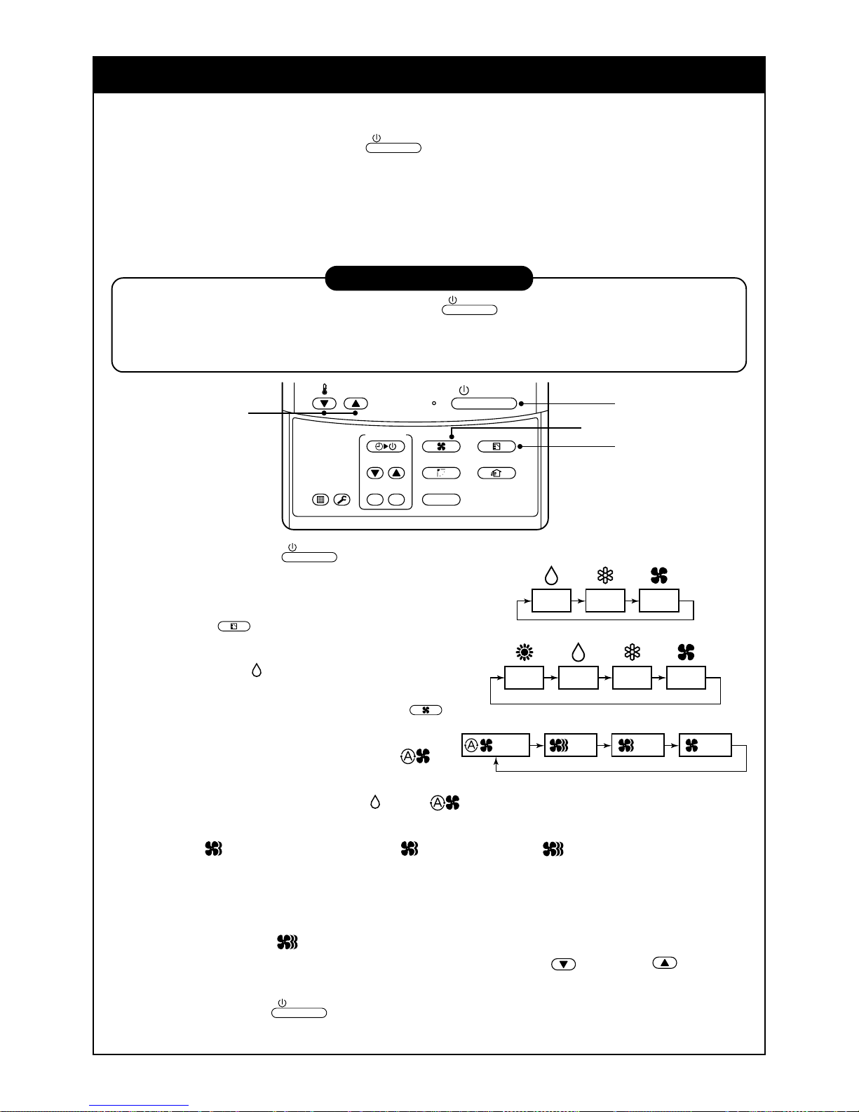
33
UTILISATION CORRECTE
Lorsque vous utilisez le climatiseur pour la première fois ou lorsque vous modifiez SET DATA
(PARAMETRAGE), suivez la procédure ci-dessous. Dès la fois suivante, le fonctionnement commencera
selon l’état défini en appuyant sur la touche
ON / OFF
.
Préparation
Activez l’interrupteur général et/ou le disjoncteur.
• Lorsque le système est mis sous tension, la section d’affichage apparaît sur la télécommande.
* Après avoir mis le climatiseur sous tension, la télécommande n’accepte aucune opération pendant environ
1 minute, mais il ne s’agit pas d’une panne.
CONDITIONS REQUISES
• Ne faites fonctionner le climatiseur qu’avec la touche
ON / OFF
sans désactiver l’interrupteur général ni
le disjoncteur.
• Ne désactivez pas le disjoncteur pendant le fonctionnement du climatiseur.
• Activez le disjoncteur 12 heures ou davantage avant de démarrer le climatiseur après un arrêt prolongé.
1
Appuyez sur la touche
ON / OFF
.
Le témoin de fonctionnement s’allume et le
fonctionnement commence.
2
Sélectionnez le mode de fonctionnement à l’aide
de la touche
MODE
.
Chaque pression sur cette touche modifie l’affichage
dans l’ordre indiqué à droite.
• La fonction “Mode
SEC” n’est pas disponible sur le
Type à pression statique élevée et à conduit dissimulé.
3
Sélectionnez le volume d’air avec la touc he
FAN
.
Chaque pression sur cette touche modifie
l’affichage dans l’ordre indiqué à droite.
• Lorsque le volume d’air correspond à “AUTO
”,
le volume d’air diffère en fonction de la température
ambiante.
• En mode DRY (DESHUMIDIFICATION)
, “AUTO ” apparaît et le volume d’air correspond à LOW
(FAIBLE).
• En mode Chauffage, si la température ambiante n’est pas suffisamment élevée avec le mode de ventilation
sur “LOW
” (FAIBLE), sélectionnez “MED. ” (MOYEN) ou “HIGH ” (ELEVE).
• La température de détection du capteur est celle à proximité de l’aspiration de l’air de l’unité intérieure. Elle
est donc légèrement différente de la température ambiante, selon l’état de l’installation. La valeur de
configuration est un critère de la température ambiante. (La vitesse automatique de l’air ne peut pas se
sélectionner en mode FAN)
• La fonction volume d’air n’est pas prévue sur le Type à pression statique élevée et conduit dissimulé seule
la vitesse de l’air HIGH
s’affiche.
4
Déterminez la température définie en appuyant sur la touche “TEMP. ” ou “TEMP. ”.
Arrêt
Appuyez sur la touche
ON / OFF
.
Le témoin de fonctionnement s’éteint et le fonctionnement s’arrête.
1
3
2
4
ON / OFF
FAN
TEMP.
SWING/FIXTIME
MODE
VENT
UNITSET CL
FILTER
RESET
TEST
TIMER SET
HEAT DRY COOL FAN
Modèle à thermopompe seulement
DRY COOL FAN
Modèle de refroidissement seulement
(Déshumidificateur)
LOW MED. HIGH
AUTO

34
CONDITIONS REQUISES
[En mode refroidissement]
• Le fonctionnement démarre après environ 1 minute.
[En mode chauffage seulement (uniquement pour le modèle à thermopompe)]
• En mode Chauffage, le ventilateur peut continuer de fonctionner pendant environ 30 secondes après
l’arrêt du climatiseur.
• Le ventilateur intérieur continue le préchauffage pendant 3 ou 5 minutes après l’arrêt puis il souffle l’air
chaud. ( l’affichage apparaît sur l’afficheur de la télécommande)
• Lorsque la température de la pièce atteint la température configurée et que l’unité extérieure s’arrête, la
vitesse de l’air ralentit énormément et le volume d’air diminue d’autant.
• En mode HEA T , si la température ambiante atteint la température configurée, l’unité extérieure
s’arrête, le flux d’air devient LOW et le volume d’air diminue.
• En mode dégivrage, le ventilateur s’arrête de manière à ce que l’air froid ne soit pas refoulé et PREDEF s’affiche.
REGLAGE DU SENS DE SOUFFLAGE
Pour augmenter l’effet de refroidissement ou de chauffage, utilisez le volet de refoulement en
l’orientant de différentes façons selon le mode de fonctionnement.
Comme vous le sav ez, l’air froid s’accumule dans le bas et l’air chaud dans le haut,
PRUDENCE
En mode refroidissement placez le volet horizontalement.
En refroidissement si le refoulement s’eff ectue vers le bas, la surface de la bouche de refoulement, ou le
volet, se couvre de condensats, qui risquent de tomber au sol.
CONDITIONS REQUISES
• En mode chauffage si le refoulement est horizontal, la température risque d’être encore plus irrégulière
dans la pièce.
Type cassette à 4 voies de refoulement
• Lorsque le climatiseur s’arrête, le volet de refoulement s’oriente automatiquement vers le bas.
• Lorsque le climatiseur est en état prêt au chauffage, le
volet de refoulement s’oriente vers le haut.
L’oscillation commence après avoir annulé l’état prêt
au chauffage mais SWING
s’affiche sur la
télécommande même si l’état est prêt au chauffage.
[En mode refroidissement]
Utilisez le volet de refoulement avec le point de consigne horizontal.
[En mode chauffage
(uniquement pour le modèle à thermopompe)]
Utilisez le volet de refoulement a vec le point de consigne
vers le bas.

35
Mode de réglage de la direction de l’air
Appuyez sur la touche
SWING/FIX
.
1
La direction de l’air change chaque fois que vous appuyez sur la touche.
En mode Chauffage
Orientez le volet de refoulement de l’air v ers le bas .
Si vous l’orientez vers le haut, l’air chaud pourrait ne pas atteindre le sol.
En mode Refroidissement/Déshumidification
Orientez le volet de refoulement de l’air v ers le haut.
Si vous l’orientez vers le bas, la condensation pourrait adhérer à la
surface de la bouche de refoulement ou dégoutter.
Réglage initial
Réglage initial
1, 2, 3 4
En mode
VENTILATION
Dans tous
les modes
Affichage à l’arrêt de l’oscillation
Réglage initial
Série de
fonctionnement
Ventilation/
Chauffage
Refroidissement/
Déshumidification
ON / OFF
FAN
TEMP.
SWING/FIXTIME
MODE
VENT
UNITSET CL
FIL TER
RESET
TEST
TIMER SET
N˚ unité 1-1Pas
d’affichage
N˚ unité 1-2
N˚ unité 1-4 N˚ unité 1-3
Mode de démarrage de l’oscillation
2
Appuyez sur la touche
SWING/FIX
.
Orientez le volet sur la position la plus
basse, puis appuyez à nouveau sur la
touche
SWING/FIX
.
• [SWING ] s’affiche et la direction de l’air
change automatiquement de haut en bas.
Si vous contrôlez plusieurs unités intérieures
avec une télécommande, vous pouvez
sélectionner chaque unité intérieure et régler la
direction de l’air séparément .
Comment arrêter l’oscillation
3
Appuyez encore sur la touche
SWING/FIX
pendant l’oscillation du volet de refoulement de
l’air.
• Vous pouvez arrêter le volet de refoulement de
l’air dans la position voulue. Vous pouvez
ensuite régler la direction de l’air sur la position
la plus haute en appuyant sur la touche
SWING/FIX
.
* Si le volet de refoulement de l’air est orienté
vers le bas en mode refroidissement/
déshumidification, il ne s’arrête pas.
Si vous arrêtez le volet alors qu’il se dirige
vers le bas pendant l’oscillation, il s’arrête
après s’être déplacé dans la 3
ème
position à
partir de la plus haute.
4
UNIT
• Pour configurer séparément la direction de l’air,
appuyez sur la touche
UNIT
pour afficher
chaque n° d’unité intérieure si vous effectuez le
contrôle de groupe. Configurez alors la direction de l’air de l’unité intérieure affichée.
• Si l’affichage est vide, vous pouvez faire
fonctionner toutes les unités intérieures de la
même façon.
• Chaque fois que vous appuyez sur la touche
UNIT
l’affichage change de la façon illustrée
par la figure.

36
Selon la forme et l’aménagement de la pièce l’air froid et l’air chaud peuvent être ref oulés dans deux ou trois
directions. Pour les détails, contactez votre revendeur.
INFORMATIONS
• En mode refroidissement avec refoulement vers le bas , de la condensation peut tomber sur l’armoire ou
sur le volet horizontale et dégoutter.
• En mode chauffage si le refoulement est horizontal, la température risque d’être encore plus irrégulière
dans la pièce.
• Ne bougez pas le volet horizontal avec les mains pour ne pas provoquer de dysfonctionnement.
Sélectionnez la direction du volet horizontal à l’aide de l’interrupteur “Flap operation” de la
télécommande. Le volet horizontal ne s’arrête pas immédiatement même si vous appuyez sur la touche .
Réglez la position d’arrêt, appuyez sur l’interrupteur.
Type cassette à 2 voies de refoulement
[En mode refroidissement]
Utilisez le volet de refoulement avec le point de consigne horizontal.
[En mode chauffage
(uniquement pour le modèle à thermopompe)]
Utilisez le volet de refoulement a vec le point de consigne
vers le bas.
Configuration de la direction et l’air et de l’oscillation
1
Appuyez sur la touche
SWING/FIX
pendant le fonctionnement.
• [SWING ] s’affiche et la direction de l’air change
automatiquement de haut en bas.
Si vous contrôlez plusieurs unités intérieures avec une
télécommande, vous pouvez sélectionner chaque unité
intérieure et régler la direction de l’air séparément .
2
Appuyez encore sur la touche
SWING/FIX
pendant l’oscillation
du volet de refoulement de l’air.
• Vous pouvez arrêter le volet de refoulement de
l’air dans la position voulue.
3
UNIT
• Pour configurer séparément la direction de l’air, appuyez sur la touche
UNIT
pour afficher chaque n°
d’unité intérieure si vous effectuez le contrôle de groupe. Configurez alors la direction de l’air de l’unité
intérieure affichée.
• Si l’affichage est vide, vous pouvez faire fonctionner toutes les unités intérieures de la même façon.
• Chaque fois que vous appuyez sur la touche
UNIT
l’affichage change de la façon illustrée par la figure.
Type cassette à 1 voie de refoulement (Série 1H)
Réglage de la direction de l’air haut/bas
[En mode refroidissement]
En mode refroidissement, utilisez le volet de refoulement avec le point
de consigne horizontal pour que l’air froid se diffuse dans toute la pièce.
[En mode chauffage (uniquement pour le modèle à thermopompe)]
En mode chauffage, utilisez le volet de refoulement avec le point de consigne
vers le bas pour que l’air chaud se diffuse vers le bas de la pièce .
Réglage de la direction de l’air droite/gauche
Pour changer la direction, de droite à gauche , réglez la g rille v erticale à
l’intérieur du volet du refoulement de l’air dans la direction voulue.
Configuration de la direction et l’air et de l’oscillation
Consultez la description du Type à cassette avec refoulement de l’air à 2 voies.
ON / OFF
FAN
TEMP.
SWING/FIXTIME
MODE
VENT
UNITSET CL
FILTER
RESET
TEST
TIMER SET
1, 2 3
N˚ unité 1-1Pas
d’affichage
N˚ unité 1-2
N˚ unité 1-4 N˚ unité 1-3

37
Type dans faux-plafon, Type cassette à 1 voie de refoulement (Série 2SH)
• Lorsque le climatiseur s’arrête, le volet horizontal (plaque de réglage de la direction vers le
haut/bas) s’oriente automatiquement vers le haut.
• Lorsque le climatiseur est prêt au chauffage, le volet horizontal (plaque de réglage de la
direction vers le haut/bas) s’oriente automatiquement vers le haut. L’oscillation commence
après avoir annulé l’état prêt au chauffage mais SWING
s’affiche sur la télécommande
même si l’état est prêt au chauffage.
Mode de réglage de la direction de l’air
Appuyez sur la touche
SWING/FIX
pendant le fonctionnement.
1
La direction de l’air change chaque fois que vous appuyez sur la touche.
1, 2, 3 4
En mode
VENTILATION
Dans tous
les modes
Affichage à l’arrêt de l’oscillation
Réglage initial
Série de
fonctionnement
Ventilation/
Chauffage
Refroidissement/
Déshumidification
FAN
SWING/FIXTIME
MODE
VENT
UNITSET CL
FILTER
RESET
TEST
TIMER SET
N˚ unité 1-1Pas
d’affichage
N˚ unité 1-2
N˚ unité 1-4 N˚ unité 1-3
En mode Chauffage
Réglez le volet horizontal (plaque de réglage
de la direction vers le haut/bas) vers le bas.
Si vous l’orientez vers le
haut, l’air chaud pourrait
ne pas atteindre le sol.
En mode Refroidissement/Déshumidification
Réglez le volet horizontal (plaque
de réglage de la direction vers le
haut/bas) vers le haut. Si vous
l’orientez vers le bas, la condensation pourrait adhérer à la surface
de la bouche de refoulement ou
dégoutter.
Comment démarrer l’oscillation
2
Appuyez sur la touche
SWING/FIX
.
Réglez l’orientation du volet horizontal (plaque de
réglage de la direction du refoulement vers le haut/
bas) sur la position la plus basse, puis appuyez à
nouveau sur la touche
SWING/FIX
.
• [SWING ] s’affiche et la direction de l’air change
automatiquement de haut en bas.
Si vous contrôlez plusieurs unités intérieures avec une
télécommande, vous pouvez sélectionner chaque unité
intérieure et régler la direction de l’air séparément.
Comment arrêter l’oscillation
3
Appuyez encore sur la touche
SWING/FIX
pendant
l’oscillation du volet horizontal de refoulement de
l’air.
• Vous pouvez arrêter le volet horizontal de refoulement
de l’air dans la position voulue. Vous pouvez ensuite
régler la direction de l’air sur la position la plus haute en
appuyant sur la touche
SWING/FIX
.
* Si le volet de refoulement de l’air est orienté vers le
bas en mode refroidissement/déshumidification, il ne
s’arrête pas.
Si vous arrêtez le volet horizontal alors qu’il se dirige
vers le bas pendant l’oscillation, il s’arrête après
s’être déplacé dans la 3ème position à partir de la
plus haute.
4
UNIT
• Pour configurer séparément la direction de l’air,
appuyez sur la touche
UNIT
pour afficher chaque n°
d’unité intérieure si vous effectuez le contrôle de
groupe. Configurez alors la direction de l’air de l’unité
intérieure affichée.
• Si l’affichage est vide, vous pouvez faire fonctionner
toutes les unités intérieures de la même façon.
• Chaque fois que vous appuyez sur la touche
UNIT
l’affichage change de la façon illustrée par la figure.
Réglage initial
Réglage initial

38
Réglage de la direction de l’air droite/gauche
Pour changer la direction de refoulement de l’air, de droite à gauche, réglez le volet vertical à l’intérieur du
volet de la refoulement de l’air dans la direction voulue.
INFORMATIONS
• En mode refroidissement avec refoulement vers le bas , de la
condensation peut tomber sur l’armoire ou sur le volet
horizontale et dégoutter.
• En mode chauffage si le refoulement est horizontal, la
température risque d’être encore plus irrégulière dans la pièce.
Type mural haut
Réglage de la direction de l’air haut/bas
[En mode refroidissement]
En mode refroidissement, utilisez le volet de refoulement avec le
point
de consigne horizontal pour que l’air froid se diffuse dans toute la
pièce.
[En mode chauffage (uniquement pour le modèle à
thermopompe)]
En mode chauffage, utilisez le v olet de refoulement avec le point de
consigne
vers le bas pour que l’air chaud se diffuse vers le bas de la pièce .
INFORMATIONS
• En mode refroidissement avec refoulement vers le bas , de la
condensation peut tomber sur l’armoire ou sur le volet
horizontale et dégoutter .
• En mode chauffage si le refoulement est horizontal, la
température risque d’être encore plus irrégulière dans la
pièce.
• Ne bougez pas le volet horizontal avec les mains pour ne pas
provoquer de dysfonctionnement. Sélectionnez la direction du
volet horizontal à l’aide de l’interrupteur
SWING/FIX
de la
télécommande. Le volet horizontal ne s’arrête pas
immédiatement même si vous appuyez sur la touche . Réglez
la position d’arrêt, appuyez sur l’interrupteur.
Réglage de la direction de l’air droite/gauche
Pour changer la direction de refoulement de l’air, de droite à gauche,
réglez le volet vertical à l’intérieur du volet de la refoulement de l’air
dans la direction voulue.
Configuration de la direction et l’air et de
l’oscillation
Série 1H: Consultez la description du “Type à cassette avec
refoulement de l’air à 2 v oies”.
Série 2H: Consultez la description du “Type dans faux-plafon, Type
cassette à 1 voie de ref oulement (Série 2SH)”.

39
Type armoire posée au sol
[En mode refroidissement]
En mode refroidissement, utilisez le volet de refoulement a vec
le point
de consigne horizontal pour que l’air froid se diffuse dans
toute la pièce.
[En mode chauffage (uniquement pour le modèle à
thermopompe)]
En mode chauffage, utilisez le v olet de refoulement avec le
point de consigne
vers le bas pour que l’air chaud se diffuse vers le bas de la
pièce.
Comment changer la bouche de refoulement de l’air
Pour changer la bouche de refoulement de l’air procédez de la sorte.
1
Enlevez les deux vis de fixation de la bouche de
refoulement de l’air.
(Les vis de fixation seront réutilisées).
2
Introduisez la main dans la bouche de refoulement de
l’air et poussez légèrement puis sortez la bouche de
refoulement de l’air de son crochet placé à l’arrière.
3
Soulevez la bouche de refoulement de l’air ver s le
haut et sortez-le.
4
Inversez la bouc he de refoulement de l’air et fixez-le
sur l’unité centrale.
Vérifiez si les quatre crochets (deux de chaque côté à
l’arrière et dans le bas) sont bine en place.
5
Veillez à bien serrer les vis de fixation de la bouche
de refoulement de l’air de façon à ce que celui-ci ne
sorte pas.

40
Type à châssis vertical posé au sol
Réglage de la direction de l’air haut/bas
[En mode refroidissement]
En mode refroidissement, déplacez le volet de refoulement à la main et utilisez le point
de refoulement de l’air horizontal pour que l’air froid se diffuse dans toute la pièce.
[En mode chauffage (uniquement pour le modèle à thermopompe)]
En mode chauffage, déplacez le volet de refoulement à la main et utilisez le volet
horizontal avec le point de consigne vers le bas pour que l’air chaud se diffuse vers le
bas de la pièce.
Réglage de la direction de l’air droite/gauche
[Si vous utilisez des directions de l’air asymétriques]
Soulevez légèrement le volet vers le haut et dirigez-le dans
la direction voulue, puis abaissez-le
Dans ce cas, n’utilisez pas la fonction Oscillation.
1
2
Dans ce cas, n’utilisez
pas la fonction Oscillation.
ON / OFF
FAN
TEMP.
SWING/FIXTIME
MODE
VENT
UNITSET CL
FILTER
RESET
TEST
TIMER SET
1, 2 3
N˚ unité 1-1Pas
d’affichage
N˚ unité 1-2
N˚ unité 1-4 N˚ unité 1-3
[Avec l’oscillation automatique]
1
Appuyez sur la touche
SWING/FIX
pendant le
fonctionnement.
• [SWING ] s’affiche et la direction de l’air change
automatiquement de haut en bas.
Si vous contrôlez plusieurs unités intérieures avec
une télécommande, vous pouvez sélectionner
chaque unité intérieure et régler la direction de l’air
séparément .
2
Appuyez encore sur la touche
SWING/FIX
pendant
l’oscillation du volet de refoulement de l’air.
• Vous pouvez arrêter le volet de refoulement de
l’air dans la position voulue.
3
UNIT
• Pour configurer séparément la direction de l’air,
appuyez sur la touche
UNIT
pour afficher chaque
n° d’unité intérieure si vous effectuez le contrôle de
groupe. Configurez alors la direction de l’air de
l’unité intérieure affichée.
• Si l’affichage est vide, vous pouvez faire fonctionner
toutes les unités intérieures de la même façon.
• Chaque fois que vous appuyez sur la touche
UNIT
l’affichage change de la façon illustrée par la figure.
INFORMATIONS
• En mode refroidissement avec refoulement vers le bas , de la condensation peut tomber sur l’armoire ou
sur le volet horizontale et dégoutter.
• En mode chauffage si le refoulement est horizontal, la température risque d’être encore plus irrégulière
dans la pièce.
• Ne bougez pas le volet directement avec les mains pendant l’oscillation pour ne pas provoquer de
dysfonctionnement. Le volet vertical ne s’arrête pas immédiatement même si vous appuyez sur la
touche
SWING/FIX
. Réglez la position d’arrêt, appuyez sur l’interrupteur
SWING/FIX
.
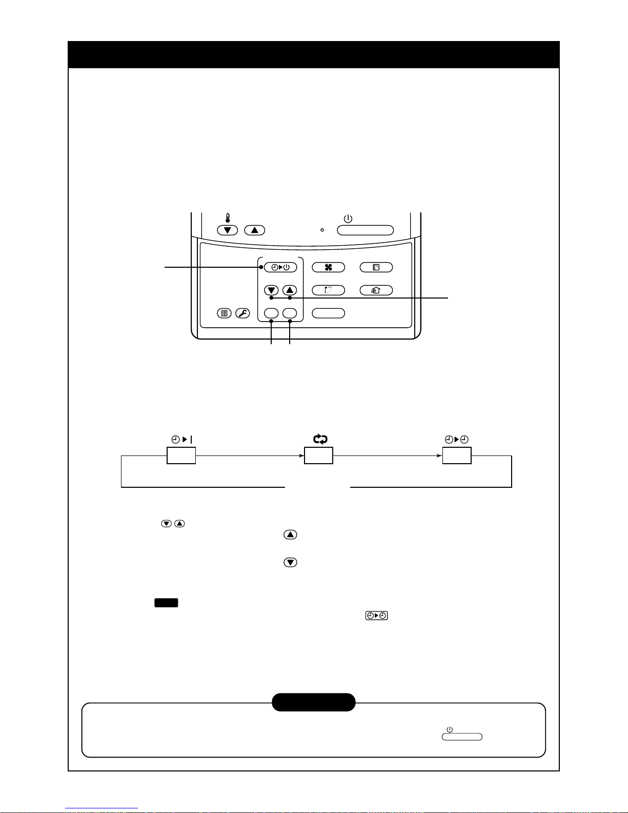
41
FONCTIONNEMENT PAR MINUTERIE
Vous pouvez sélectionner l’un des trois types de fonctionnement de la minuterie:
Désactivation de la minuterie :
Le fonctionnement s’arrête lorsque l’heure de la minuterie a atteint l’heure prédéfinie .
Répétition Désactivation de la minuterie :
Le fonctionnement s’arrête chaque fois que l’heure prédéfinie est dépassée.
Activation de la minuterie :
Le fonctionnement démarre lorsque l’heure de la minuterie a atteint l’heure prédéfinie.
Fonctionnement par minuterie
1
Appuyez sur la touche TIMER SET (REGLAGE MINUTERIE).
• L’affichage de la minuterie (type) change chaque fois que vous appuyez sur la touche.
• SET DATA et l’affichage de l’horaire de la minuterie clignotent.
2
Appuyez sur
TIME
pour sélectionner “SET TIME” (HEURE DEFINIE).
Chaque fois que vous appuyez sur la touche , l’heure définie augmente d’une demi-heure (30 minutes).
L’heure définie maximum est de 72 heures.
Chaque fois que vous appuyez sur la touche
, l’heure définie diminue d’une demi-heure (30 minutes).
L’heure définie minimum est d’une demi-heure.
3
Appuyez sur la touche SET (REGLA GE).
• L’affichage
SETTING
disparaît et l’heure de la minuterie apparaît.
(Lorsque ON timer est activé, l’heure de la minuterie, ON timer
sont affichés et les autres affichages
disparaissent.)
Annulation du fonctionnement par minuterie
4
Appuyez sur la touche CL (ANNULER).
• TIMER (MINUTERIE) disparaît.
REMARQUE
• Quand le fonctionnement s’arrête lorsque la minuterie a atteint l’heure définie, la minuterie de Répétition
DESACTIVATION reprend le fonctionnement lorsque vous appuyez sur la touche
ON / OFF
et arrête le
fonctionnement une fois que l’heure de la minuterie a atteint l’heure définie.
4
3
2
1
ON / OFF
FAN
TEMP.
SWING/FIXTIME
MODE
VENT
UNITSET CL
FILTER
RESET
TEST
TIMER SET
OFF
(DESACTIVATION par minuterie) (Répétition DESACTIVATION par minuterie)
Pas d’affichage
(ACTIVATION par minuterie)
OFF ON

42
INSTALLATION
Lieu d’installation
AVERTISSEMENT
• Choisissez un lieu d’installation en mesure de supporter sans problème le poids de l’unité.
Si l’endroit choisi pour l’installation n’est pas assez robuste pour supporter l’unité, celle-ci risque de
tomber et de blesser quelqu’un.
PRUDENCE
• N’installez pas l’unité dans un endroit où des fuites de gaz risquent de se produire.
L’unité pourrait enflammer les fuites de gaz s’accumulant à proximité de l’unité.
CONDITIONS REQUISES
• Un endroit permettant de mettre à niveau l’unité
• Un endroit offrant assez d’espace pour effectuer l’entretien de l’unité en toute sécurité
• Un endroit où l’eau s’écoulant de l’unité ne pose pas de problème
Evitez les endroits suivants :
• Les endroits présentant une concentration élevée de sel (bord de mer) ou de gaz sulfureux (sources
thermales) (Pour utiliser l’unité dans ces endroits, un entretien spécial est nécessaire).
• Les endroits produisant de l’huile (y compris l’huile pour machine), de la vapeur, de la fumée grasse ou
des gaz corrosifs.
• Les endroits où sont utilisés des solvants organiques
• Les endroits à proximité d’appareils générant des signaux à haute fréquence
• Les endroits où l’unité extérieure souffle dans la direction de la fenêtre d’un voisin
• Les endroits où le bruit de l’unité extérieure pose un problème
• Les endroits offrant une mauvaise circulation d’air
Câbles électriques
AVERTISSEMENT
Vérifiez si la mise à la terre est effectuée correctement.
La mise à la terre est indispensable. Une mise à la terre incomplète risque de prov oquer une électrocution.
PRUDENCE
Vérifiez sir le disjoncteur est mis en place.
Il est indispensable de brancher un disjoncteur. Sinon, vous risqueriez de vous électrocuter.
Vérifiez si les fusibles utilisés ont un pouvoir de coupure adéquat.
En utilisant un fil métallique ou un fil en cuivre vous risquez de provoquer un incendie ou un
dysfonctionnement.
Pour l’alimentation électrique utilisez un circuit dont la tension nominale ne dessert que le climatiseur .
Pour déconnecter l’appareil du secteur.
Cet appareil doit être connecté au secteur via un disjoncteur ou un interrupteur ayant une séparation de
contact d’au moins 3 mm.

43
ENTRETIEN
Nettoyage du filtre à air
• Si [FILTER] s’affiche sur la télécommande , procédez à l’entretien du filtre à air.
• L’encrassement du filtre à air réduit les performances du refroidissement/chauffage .
AVERTISSEMENT
Avant de nettoyer le climatiseur, assurez-vous de désactiver l’interrupteur général.
• N’effectuez pas vous-même l’entretien et/ou le nettoyage quotidien du filtre.
Le nettoyage du filtre à air et des autres pièces de l’unité intérieure impliquant un travail en hauteur
dangereux, assurez-vous qu’il soit effectué par une personne chargée de l’entretien. Ne le faites pas
vous-même.
<Entretien quotidien>
• Faites exécuter l’entretien quotidien, y compris le nettoy age du filtre par du personnel qualifié, surtout sur le
modèles suivants :
Type cassette à 4 voies de refoulement Type standard à conduit dissimulé Type dans faux-plafond
Type cassette à 2 voies de refoulement Type Conduit Mince
Type cassette à 1 voie de refoulement Conduit dissimulé type à pression statique élevée
ON / OFF
FAN
TEMP.
SWING/FIXTIME
MODE
VENT
UNITSET CL
FILTER
RESET
TEST
TIMER SET
CODE No.
UNIT No.
TEST
SETTING
DATA
SET
R.C. No.
H
Affichage de FILTER
Il s’allume lorsqu’il est temps de nettoyer le filtre à air.
Remise à zéro de FILTER
Après le nettoyage, appuyez sur la touche FILTER
L’affichage FILTER disparaît.
Type cassette à
4 voies de refoulement
Type dans faux-plafond Type Conduit Mince
Type cassette à
2 voies de refoulement
Type standard
à conduit dissimulé
Type cassette à
1 voie de refoulement
Conduit dissimulé type
à pression statique élevée
PAS BON
PAS BON
PAS BON
PAS BON PAS BON
PAS BON
PAS BON

44
Type mural haut
(Modèle : série 1H)
• Poussez la projection au centre du filtre à air. L’attache est sortie.
• Défaites l’attache du filtre à air, tirez sur le filtre à air v ers le bas tout en
le poussant vers le côté de l’unité.
(Modèle : série 2H)
• Ouvrez la grille d’aspiration de l’air.
Soulevez la grille d’aspiration de l’air vers le haut jusqu’à l’horizontale.
• Saisissez les poignées gauche et droite du filtre à air et soulevez-le
légèrement puis tirez-le vers le bas pour le sortir du porte filtre.
Poussez le filtre
à air et tirez-le
vers le bas.
Façade
(inférieure)
Bouton du
filtre à air
Support du filtre
Type armoire posée au sol
• Poussez légèrement vers le bas le haut de la bouche d’aspiration et
tirez vers vous pour l’enlever.
• Sortez le filtre à air de l’intérieur de la bouche d’aspiration.
Type à châssis vertical dissimulé au sol
• Poussez vers le bas le crochet du filtre à air de la façade (côté
inférieur).
• Tirez le filtre à air vers vous pour l’enlever.
Type à châssis vertical posé au sol
Enlèvement/fixation du filtre à air
• Tirez le filtre à air vers vous.
• Pour fixer le filtre à air, introduisez-le dans la carrosserie de l’unité et
poussez dessus.
REMARQUE
• Pour nettoyer le filtre à air, utilisez un produit de nettoyage ou une brosse .
Si les tâches sont résistantes, lav ez le filtre à air dans de l’eau tiède savonneuse.
• Après le lavage, rincez bine le filtre à air et faites-le sécher à l’ombre.
• Remontez le filtre à air une fois propre.

45
Retournez le filtre à air.
• Introduisez le haut du filtre à air en vérifiant si ses bords droit et gauche s’adaptent à l’unité intérieure puis
fixez-le solidement.
• Fermez la grille d’aspiration de l’air.
Si le voyant du FILTRE placé sur l’unité intérieure s’éclaire, appuyez sur la touche FILTER (FILTRE) de la
télécommande ou sur la touche TEMPORARY (PROVISOIRE) sur l’unité intérieure pour éteindre le voyant.
Support du filtre
Ne pas utiliser.
Poudre
abrasive
Benzène
Diluant
Lingette
pour sol
Nettoyage de la grille d’aspiration de l’air.
1. Otez la grille d’aspiration de l’air
Maintenez les deux côtés de la grille d’aspiration de l’air et
ouvrez-la vers le haut.
Déplacez le levier central v ers la gauche et ôtez la g rille.
2. Lavez-la à l’eau à l’aide d’une éponge souple ou d’une
serviette.
(N’utilisez aucune brosse dure métallique ou en autres
matériaux).
• Le recours à ce type d’objet dur égratigne la surface de
la grille et écaille la couche de peinture.
• Si la grille d’aspiration de l’air est très sale, nettoyez-la
avec un savon à vaisselle neutre et rincez-la ensuite à
l’eau.
3. Essuy ez l’eau à la surface de la grille d’aspiration de l’air et
séchez-la.
4. Enfilez les leviers droit et gauche de la grille d’aspiration de
l’air sur les axes placés des deux côtés du climatiseur et
poussez-les à fond, puis poussez le le vier central.
5. Vérifiez si le levier centr al est entièrement enfoncé et
fermez la grille d’aspiration de l’air.
• Poussez les parties où se trouvent les flèches (quatre)
au bas de la grille d’aspiration de l’air pour vérifier si la
grille est complètement fermée.
Nettoyage de l’unité principale/télécommande
PRUDENCE
• Dépoussiérez-les avec un chiffon doux et sec.
• Vous pouvez utiliser un chiffon imbibé d’eau froide pour
nettoyer l’unité intérieure si elle est très sale .
• N’utilisez jamais un chiffon humide pour nettoyer la
télécommande.
• N’utilisez pas un chiffon traité chimiquement pour
nettoyer l’unité ou ne l’y abandonnez pas longtemps.
Il pourrait endommager ou décolorer la surface de
l’unité.
• N’utilisez ni benzine, ni diluant, ni cire, ni solvants
similaires pour le nettoyage .
Ils pourraient fissurer ou déformer la surface en
plastique.

46
Si vous prévoyez de ne pas utiliser l’unité pendant
plus d’un mois
1. Faites tourner le ventilateur pendant 3 ou 4 heures pour
déshumidifier l’intérieur de l’unité
• Faites marcher en mode FAN.
2. Arrêtez le climatiseur et désactivez l’interrupteur général ou le
disjoncteur.
Vérifications avant utilisation
1. Vérifiez que les filtres à air soient montés.
2. Vérifiez que la sortie ou l’entrée de l’air ne soient pas bloquées.
3. Connectez l’interrupteur général ou le disjoncteur au secteur
pour mettre le climatiseur sous tension.
REMARQUE
Si le système de climatisation est utilisé régulièrement, le nettoyage et l’entretien des unités intérieures/
extérieures sont fortement recommandés.
En général, si une unité intérieure est utilisée quotidiennement pendant 8 heures environ, les unités
intérieures/extérieures devront être netto yées au moins une fois tous les 3 MOIS.
Le nettoyage et l’entretien doivent être effectués par un professionnel.
L’absence de nettoyage régulier des unités intérieures/extérieures se soldera par une baisse des
performances, du givre, une fuite d’eau, voire une panne du compresseur.
SUGGESTIONS CONCERNANT LE FONCTIONNEMENT ECONOMIQUE
Maintenez la température ambiante à un niveau confortable.
Nettoyez les filtres à air.
Le flux d’air et les performances seront réduits si les filtres à air s’encrassent.
N’ouvrez pas les portes et fenêtres plus souvent qu’il le faut.
Pour conserver l’air froid ou chaud dans la pièce , n’ouvrez pas les portes et fenêtres plus souv ent qu’il le faut.
Rideaux des fenêtres
Lors du refroidissement, fermez les rideaux pour éviter la lumière directe du soleil.
Lors du chauffage, fermez les rideaux pour conserver la chaleur à l’intérieur.
Faites en sorte que l’air circule uniformément dans la pièce.
Réglez le sens du flux d’air de sorte que l’air circule uniformément dans la pièce.
Nettoyez avec un
chiffon doux et sec !
S’il n’a pas servi
pendant longtemps,
faites-le sécher !
Commandez
Mince, quel froid !
Nettoyez, s’il vous plaît.
Fermez, s
’il
vous pla
ît.
Souffle ascendant
Souffle descendant
Réglage du flux d’air
Air froid
et sec
Air
chaud

47
FONCTIONNEMENT ET PERFORMANCES DU CLIMATISEUR
Vérifications avant utilisation
• Vérifiez si le fil de mise à la terre est débranché ou pas ne place.
• Vérifiez si le filtre à air est monté sur l’unité intérieure.
Puissance de chauffage
(uniquement pour le modèle à thermopompe)
• Pour le chauffage, on adopte une thermopompe qui aspire l’air extérieur et refoule l’air chaud dans la pièce.
Si la température de l’air extérieur s’abaisse, la puissance de chauffage diminue.
• Si la température de l’air extérieur est basse, nous vous recommandons d’utiliser en même temps un autre
appareil de chauffage.
Dégivrage pendant le fonctionnement en mode chauffage
(uniquement pour le modèle à thermopompe)
• Si du givre se forme sur l’unité extérieure pendant le chauffage, le mode de fonctionnement passe
automatiquement au mode dégivrage pour accroître l’effet chauffant (pendant environ 2 ou 10 minutes)
• Pendant le dégivrage les ventilateurs des unité intérieures et extérieures s’arrêtent.
Protection pendant 3 minutes
• L’unité ne fonctionne pas du tout pendant environ 3 minutes après le redémarrage du climatiseur à la suite d’un
arrêt, ou lorsque l’interrupteur est activé. Cela permet de protéger le système.
Panne de courant
• En cas de panne de courant pendant le fonctionnement, toutes les opérations cessent.
• Lors du redémarrage, appuyez à nouveau sur la touche ON/OFF.
Rotation du ventilateur de l’unité arrêtée
• Lorsque les unités intérieures fonctionnent, le ventilateur des unités intérieures en attente tourne pour protéger
la machine pendant environ 1 heure pendant quelques minutes.
Dispositif de protection (pressostat de haute pression)
Le pressostat de haute pression arrête automatiquement le climatiseur si une charge excessive lui est appliquée.
Si le dispositif de protection se déclenche, la lampe de fonctionnement reste éclairée mais le fonctionnement
cesse.
Lorsque le dispositif de protection se déclenche, les caractères “
” de la télécommande clignotent.
Le dispositif de protection se déclenche dans les cas suivants.
En mode refroidissement
• Lorsque la bouche d’aspiration ou de refoulement de l’unité extérieure est fermée.
• Lorsque un vent fort souffle sans cesse contre la bouche de refoulement de l’unité extérieure.
En mode chauffage (uniquement pour le modèle à thermopompe)
• Lorsqu’il y a trop de poussière ou de saleté sur le filtre à air de l’unité intérieure.
• Lorsque la bouche de refoulement de l’unité intérieure est bouchée.
Fonctionnement en chauffage/refroidissement du MiNi-SMMS modulaire
Sur les MiNi-SMMS modulaire chaque unité intérieure peut se contrôler séparément.
Cependant, le fonctionnement en chauffage ou en refroidissement ne peut pas avoir lieu en même temps sur les
unité intérieures branchées sur un même unité extérieure.
Si le fonctionnement en chauffage et en refroidissement est effectué en même temps, l’unité intérieure
fonctionnant en refroidissement s’arrête et “
” s’éclaire sur l’afficheur.
L’unité intérieure fonctionnant en chauffage continue de fonctionner.
Si le responsable a configuré le fonctionnement sur COOL ou HEAT, il est impossible d’effectuer un type de
fonctionnement autre que celui configuré.
Si vous effectuez un autre fonctionnement que celui configuré “
” s’éclaire sur l’afficheur et le fonctionnement
cesse.
Caractéristiques du mode chauffage (uniquement pour le modèle à thermopompe)
• L’air chaud ne sort pas immédiatement après le démarrage. Après 3 ou 5 minutes (selon la température
ambiante et la température extérieure) et lorsque l’échangeur de chaleur est chaud, l’air chaud commence
d’être soufflé.
• Pendant le fonctionnement, l’unité ex térieure peut s’arrêter si la température extérieure est trop élevée.
• Lorsque l’unité extérieure effectue le chauffage pendant que le ventilateur est en marche, le fonctionnement du
ventilateur peut être provisoirement arrêté pour l’empêcher de souffler de l’air chaud.
AVERTISSEMENT
Mettez sous tension au moins
12 heures avant de démarrer
le fonctionnement.

48
Refroidissement
Chauffage
ATTENTION
Humidité relative ambiante - inférieure à 80 %. Si le climatiseur fonctionne
à un taux supérieur, de la condensation peut se for mer à sa surface.
Température extérieure : de –15°C à 15.5°C (Temp. bulbe humide)
Température ambiante : de 15°C à 28°C (Temp. bulbe sec)
Température extérieure : de –5°C à 43°C (Temp. bulbe sec)
Température ambiante : de 21°C à 32°C (Temp. bulbe sec)
de 15°C à 24 °C (Temp. bulbe humide)
Conditions de fonctionnement du climatiseur
Pour que ses performances soient bonnes, utilisez le climatiseur dans les conditions de température ci-après.
Si le climatiseur est utilisé en dehors des conditions ci-dessus, une protection de sécurité peut entrer en fonction.
REINSTALLATION
DANGER
Demandez à votre revendeur ou à un professionnel de l’installation de réinstaller le climatiseur ou
de l’installer ailleurs et d’observer les points ci-après.
Si vous installez vous-même le climatiseur de manière inappropriée, une électrocution ou un
incendie peuvent avoir lieu.
Ne installez pas le climatiseur dans les endroits ci-après.
• Ne installez pas le climatiseur dans un endroit situé à moins de 1 m d’un téléviseur, d’une chaîne stéréo ou
d’une radio. Si l’unité est installée dans un endroit de ce type, le bruit transmis par le climatiseur affectera le
fonctionnement de ces appareils.
• Ne installez pas le climatiseur près d’une machine haute fréquence (machine à coudre ou appareil de massage
à usage professionnel, etc.) ou le climatiseur pourrait mal fonctionner.
• Ne installez pas le climatiseur dans un endroit humide ou huileux ni dans un lieu de formation de vapeur, de
suie ou de gaz corrosif.
• Ne installez pas le climatiseur dans un endroit riche en sel tel qu’une zone de bord de mer.
• Ne installez pas le climatiseur dans un endroit où de l’huile pour machines est utilisée en grande quantité.
• Ne installez pas le climatiseur dans un endroit habituellement exposé à un vent fort, tel qu’une zone de bord de
mer, un toit ou un dernier étage d’immeuble.
• Ne installez pas le climatiseur dans un lieu de formation de gaz sulfureux tel qu’une source minérale.
• Ne installez pas le climatiseur dans un véhicule ou une grue mobile.
Attention au bruit ou aux vibrations !
• Ne installez pas le climatiseur dans un endroit où le bruit de fonctionnement de l’unité extérieure ou sa sortie
d’air chaud gênent votre voisinage.
• Installez le climatiseur sur une base solide et stable, apte à éviter la transmission du bruit de fonctionnement,
d’échos et de vibrations.
• Si une unité intérieure est en fonction, il est possible que d’autres unités intérieures, qui ne sont pas en fonction,
émettent des sons.
Fente d’aspiration de l’air
La fente latérale de l’unité extérieure est une
bouche d’air de refroidissement des parties
électriques.
L’obstruction de cette bouche d’aspiration risque
de provoquer une panne électrique.
N’obstruez donc jamais cette bouche d’air et
évitez de placer des obstacles devant elle.

49
EN PRÉSENCE DES SYMPTÔMES SUIVANTS
Vérifiez les points indiqués ci-après avant de vous adressez au service de dépannage.
Il ne s’agit pas d’une panne.
Vérifiez à nouveau.
Symptôme
Unité extérieure
Unité intérieure
L’unité se met en marche ou s’arrête automatiquement.
L’unité ne fonctionne pas.
L’air n’est pas suffisamment chauffé ou refroidi.
Cause
• Le ventilateur de l’unité extérieure s’arrête automatiquement et
effectue le dégivrage-
• L’électrovanne fonctionne lorsque le dégivrage commence ou
s’achève.
• Après le démarrage, pendant le fonctionnement ou
immédiatement après l’arrêt du fonctionnement, on entend un
bruit d’eau et le bruit du fonctionnement augmente pendant 2
ou 3 minutes immédiatement après le démarrage. Il s’agit du
bruit de la circulation du réfrigérant ou de l’eau qui s’écoule du
déshumidificateur.
• Lorsque le système de climatisation fonctionne, si une unité
intérieure s’arrête elle doit encore faire circuler du réfrigérant
pour éviter la stagnation de l’huile réfrigérante.
Le réfrigérant peut donc émettre un chuintement ou de la
vapeur blanche peut s’échapper, si d’autres unités intérieures
sont en mode chauffage, ou de l’air froid peut s’échapper, si
d’autres unités intérieures sont en mode refroidissement.
• Ce son est produit lorsque l’échangeur de chaleur, etc.. se
détend et se contracte légèrement à cause des variations de
température.
• Des odeurs adhèrent au climatiseur, comme celles de mur, de
vêtement, de tapis, de cigarettes ou de cosmétiques.
• Lorsque le refroidissement ne peut pas s’effectuer parce
qu’une autre unité intérieure est en mode chauffage.
• Lorsque le responsable du climatiseur à configure le
fonctionnement sur COOL ou HEAT et qu’un fonctionnement
autre que celui configuré est en cours.
• Lorsque le ventilateur cesse de fonctionner pour empêcher le
refoulement d’air chaud.
• Un son est produit quand la soupape d’expansion fonctionne
lorsque l’unité est sous tension.
• Emission de brouillard blanc
froid ou d’eau.
• On entend parfois du bruit ou
“Pushu”
• On entend parfois “swish”.
• Une unité intérieure d’un
système de climatisation
s’arrête en émettant un bruit ou
en laissant s’échapper de la
vapeur blanche ou de l’air froid.
• On entend parfois un léger
“Pishi”.
• L’air refoulé sent mauvais.
•
s’éclaire.
• On entend un bruit, tic-toc,
lorsque le climatiseur est mis
sous tension.
• La minuterie est sur ON ou sur OFF ?
• Est-ce qu’il y a une panne de courant ?
• L’interrupteur est-il désactivé?
• Est-ce que le fusible ou le disjoncteur a sauté ?
• Est-ce que le dispositif de protection s’est déclenché ?
(La lampe de fonctionnement s’éclaire)
• Est-ce que la minuterie est sur ON ?
(La lampe de fonctionnement s’éclaire)
• Est-ce que COOL et HEAT sont sélectionnés en même
temps ? (
s’éclaire sur l’afficheur de la télécommande)
• Est-ce que la bouche d’aspiration ou de refoulement de l’unité
extérieure est bouchée?
• Est-ce qu’une porte ou une fenêtre est ouverte ?
• Est-ce que de la poussière a colmaté le filtre à air ?
• Est-ce que le volet de refoulement de l’unité intérieure est
dans la bonne position ?
• Est-ce que l’air est réglé sur LOW MED et est-ce que le mode
de fonctionnement est réglé sur FAN ?
• Est-ce que la température est correctement configurée ?
• Est-ce que COOL et HEAT sont sélectionnés en même
temps ? (
s’éclaire sur l’afficheur de la télécommande)
Si l’un de ces symptômes se présente arrêtez le fonctionnement, coupez l’alimentation électrique et adressezvous au revendeur du climatiseur.
• L’activation de l’interrupteur est instable.
• Le fusible général grille souvent ou le disjoncteur entre souvent en fonction.
• Des corps étrangers ou de l’eau ont pénétré par erreur.
• Après avoir éliminé la cause du déclenchement du dispositif de protection, l’appareil ne fonctionne toujours pas.
• D’autres situations se présentent.
Silencieux
C’est étrange.

50
Procédure
1
2
3
Description
Lorsque vous appuyez simultanément sur les touches
SET
et
TEST
pendant 4 secondes ou davantage, l’affichage de droite apparaît.
Si [Vérification de service] s’affiche, le mode passe au mode
Historique de pannes.
• [01: Ordre de l’historique de pannes] s’affiche sur la fenêtre du
n° de CODE.
• [Code de vérification] s’affiche dans la fenêtre VERIFICATION.
• [Adresse de l’unité intérieure liée à la panne] s’affiche dans la
fenêtre N° D’UNITE.
Chaque fois que vous appuyez sur la touche , , l’historique de pannes mémorisé s’affiche
dans l’ordre.
Les chiffres de N° CODE indiquent le n° de CODE [01] (dernier) –> [04] (plus ancien).
ATTENTION
N’appuyez pas sur la touche CL ou tout l’historique de pannes de l’unité intérieure sera supprimé.
Après confirmation, appuyez sur la touche
TEST
pour retourner à l’affichage habituel.
Confirmation et vérification
En cas de panne du climatiseur, le code de
vérification et le n° d’unité intérieure apparaissent
dans l’afficheur de la télécommande.
Le code de vérification ne s’affiche que lors du
fonctionnement.
Si l’affichage disparaît, faites f onctionner le
climatiseur conformément au paragraphe suivant,
Confirmation de l’historique de pannes afin de
confirmer.
Confirmation de l’historique de pannes
En cas de panne du climatiseur, l’historique de
pannes peut être confirmé avec la procédure
suivante.
(L’historique de pannes est stocké en mémoire
jusqu’à un maximum de 4 pannes).
L’historique peut être confirmé à l’état de marche ou
à l’état d’arrêt.
1. Vérifiez les pannes conformément à la procédure ci-dessus.
2. Demandez à un revendeur autorisé ou à un professionnel de l’entretien (réparation) de réparer ou
d’effectuer l’entretien du climatiseur.
3. Pour en savoir da vantage sur le code d’entretien, consultez le Manuel d’entretien.
Code de vérification N˚ de l’unité intérieure dans
laquelle une panne s’est produite
CODE No.
UNIT No.
R.C. No.
3
2
1
ON / OFF
FAN
TEMP.
SWING/FIXTIME
MODE
VENT
UNITSET CL
FILTER
RESET
TEST
TIMER SET
CODE No.
UNIT No.
R.C. No.

51
SICHERHEITSVORKEHRUNGEN
W ARNUNG
Warnhinweise zur Installation
Lassen Sie die Installation nur von Ihrem Händler oder einem Fac hbetrieb
durchführen.
Zur Installation sind fundierte Fachkenntnisse erforderlich.
Versuchen Sie nicht, das Gerät selbst zu installieren. Wird die Installation nicht
korrekt abgeschlossen, kann es zu Feuer, Stromschlag, Verletzungen oder
Wasserschäden kommen.
Verwenden sie als Zubehörteile nur Teile, die von uns zugelassen sind.
Wenn Sie keine von uns zugelassene Zubehörteile verwenden, kann es zu
Feuer, Stromschlag, Verletzungen oder Wasserschäden kommen. Überlassen Sie
auch die Installation dieser Teile einem ausgebildeten Fachmann.
Wenn Sie Geräte in einem kleinen Raum installieren, treffen Sie
Vorkehrungen, damit bei Kältemittellecks die zulässige K onzentration
nicht überschritten wird.
VORSICHT
Stimmen Sie die Maßnahmen gegen unzulässige Konzentrationen mit Ihrem Händler ab. Sollte die Menge
austretenden Kältemittels den Grenzwert überschreiten, kann es zu Sauerstoffmangel kommen.
Prüfen Sie, ob das Gerät korrekt geer det ist.
Eine Erdung ist erforderlich. Ist das System nicht geerdet, kann dies zu einem
Stromschlag führen. (Achten Sie auf die regionalen Vorschriften.)
Warnhinweise zur Benutzung
Setzen Sie sich nicht für längere Zeit dem kalten Luftstrom aus und auch
Sie darauf, dass Sie nicht unterkühlen.
Hierdurch kann es zu Gesundheitsschäden kommen.
Stecken Sie keinen Finger oder einen Gegenstand in den Luftauslass.
Da sich der Lüfter mit hoher Geschwindigkeit dreht, kann es zu Verletzungen
kommen.
Kommt es zu einem Fehler (Brandgeruch usw.), schalten Sie das Gerät
und die Stromversorgung aus und nehmen Sie Kontakt mit Ihrem Händler
auf.
Bleibt das Gerät weiter in Betrieb, kann dies zu Feuer, Stromschlägen oder zu
einem Ausfall des Geräts führen.
Warnhinweise zum Umbau/zur Reparatur
Modifizieren Sie nie das Gerät.
Feuer oder ein Stromschlag können die Folge sein.
Lassen Sie Reparaturen durch den Fachhändler bei dem Sie das
Klimagerät erworben haben durchführen.
Wird die Reparatur nicht korrekt abgeschlossen, kann es zu Feuer oder einem
Stromschlag kommen.
Wollen Sie das Gerät an anderer Stelle neu installieren, nehmen Sie mit
Ihrem Händler oder einem Fachbetrieb K ontakt auf.
Wird die Installation nicht korrekt abgeschlossen, kann es zu Feuer, Stromschlag,
Verletzungen oder Wasserschäden kommen.

52
VORSICHT
Vorsichtsmaßnahmen bei der Installation
Prüfen Sie, ob die Ablaufleitungen korrekt installiert sind, damit das
Kondensat ablaufen kann.
Sind die Leitungen nicht korrekt installiert, kann es zu Wasserschäden an Ihren
Möbeln kommen.
Prüfen Sie, ob eine Er dschluss-Sicherung installiert ist.
Die Installation einer Erdschluss-Sicherung ist erforderlich. Anderenfalls kann
ein Stromschlag die Folge sein.
Stellen Sie sicher , dass am Installationsort des Klimageräts kein
entflammbares Gas entweichen kann.
Strömt Gas aus und sammelt sich an, kann es zu einem Brand kommen.
Prüfen Sie, ob die Außeneinheit fest montiert ist.
Ist dies nicht der Fall, kann sie herunterfallen und einen Unfall verursachen.
Prüfen des Installationsorts
Das Klimagerät darf nicht mit Wasser gereinigt werden.
Ein Stromschlag könnte die Folge sein.
Stellen Sie keine Öfen in den Luftstrom des Klimageräts.
Hierdurch kann es zu einer unvollständigen Verbrennung kommen.
Lüften Sie den Raum regelmäßig, wenn in dem klimatisierten Raum ein
Ofen steht.
Bei ungenügender Lüftung kann es zu einem Sauerstoffmangel kommen.
Prüfen Sie von Zeit zu Zeit den Installationsrahmen usw.
Ist die Befestigung des Geräts beschädigt, kann es herunterfallen und
Verletzungen verursachen.
Stellen Sie keine Pflanzen oder Haustiere in den Luftstrom des
Klimageräts.
Dies kann bei Haustieren zu Krankheiten und bei Pflanzen zu
Wachstumsstörungen kommen.
Verwenden Sie in der Nähe des Klimageräts kein entzündbares Spra y
oder sprayen Sie nie direkt auf das Gerät.
Ein Brand kann die Folge sein.
Stellen Sie keine Blumenv ase oder einen anderen Behälter mit Wasser
auf das Gerät.
Dringt Wasser in das Gerät ein, kann die Isolierung der Kabel beschädigt werden
und so einen Stromschlag verursachen.
Berühren Sie die Schalter nicht mit nassen Händen.
Ein Stromschlag könnte die Folge sein.
Dieses Klimagerät eignet sich nicht für spezielle Zwecke, weder für die
Konservierung von Lebensmitteln, Präzisionsinstrumenten und
Kunstobjekten noch zur A ufzucht von Tieren, der Zucht von
Topfpflanzen usw.
Schäden können die Folge sein.
DEUTSCH

53
2-Wege/3-Wege-Zuluft
Entsprechend der Form des Raumes kann
zwischen 2-Wege- und 3-Wege-Zuluft
gewählt werden.
Details erfragen Sie bitte beim dem Fachhändler
bei dem Sie das Klimagerät erworben haben.
Luftauslass/Lüftungsklappe
Wählen Sie für den Kühl- oder
Heizbetrieb die jeweilige Luftrichtung.
Erdungsschraube
Befindet sich im Schaltkasten.
Abluftgitter
Über das Abluftgitter wird die Raumluft angesaugt.
Luftfilter
Filtert Staub und Schmutz
(Luftfilter befindet sich hinter
Lüftungsgitter).
Klammer
Klammer zu Öffnen/Schließen
des Lüftungsgitters.
Lufteinlass
Über das Abluftgitter wird
die Raumluft angesaugt.
Luftfilter
Filtert Staub und Schmutz
(Luftfilter befindet sich hinter
Mittenverkleidung).
Erdungsschraube
Befindet sich im Schaltkasten.
Mittenverkleidung
Luftauslass/Lüftungsklappe
Wählen Sie für den Kühl- oder
Heizbetrieb die jeweilige Luftrichtung.
Inneneinheit
[4-Wege-Kassetten-Modell]
MMU-AP0091H, AP0121H, AP0151H, AP0181H, AP0241H,
MMU-AP0271H, AP0301H, AP0361H, AP0481H, AP0561H
[2-Wege-Kassetten-Modell]
Lufteinlass
Lufteinlässe befinden vorn,
hinten rechts und links.
Befestigungsfuß
Luftauslass (Abluft)
Im Kühlbetrieb entweicht warme Luft.
Im Heizbetrieb entweicht kalte Luft.
Öffnung für
Stromversorgung
Öffnung für
Kältemittelrohrleitung
Der Anschluss befindet
sich im Gerät.
Außeneinheit
Erdungsschraube
Befindet sich im Schaltkasten.
Luftauslass/Lüftungsklappe
Wählen Sie für den Kühl- oder
Heizbetrieb die jeweilige Luftrichtung.
Abluftgitter
Über das Abluftgitter wird die Raumluft angesaugt.
Luftfilter
Filtert Staub und Schmutz
(Luftfilter befindet sich hinter
Lüftungsgitter).
Klammer
Klammer zu Öffnen/Schließen
des Lüftungsgitters.
MMU-AP0071MH, AP0091MH, AP0121MH, AP0151MH, AP0181MH
BEZEICHNUNGEN DER TEILE
Zubehörteile
Kabelfernbedienung
RBC-AMT31E
Einfache Kabelfernbedienung
RBC-AS21E2
Infrarot-Fernbedienung
TCB-AX21E2 RBC-AX22CE2 RBC-AX21U(W)-E2
ON / OFF
FAN
TEMP.
SWING/FIXTIME
MODE
VENT
UNITSET CL
FILTER
RESET
TEST
TIMER SET
CODE No.
UNIT No.
TEST
SETTING
DATA
SET
R.C. No.
H
˚C
TEST
SETTING

54
Wochenzeitschaltuhr
RBC-EXW21E2
Zentrale Fernbedienung
TCB-SC642TLE2
WEEKLY TIMER
ERROR
SuMoTuWeTh FrSa
PROGRAM1
PROGRAM2
PROGRAM3
SELECT ZONE
CL
SET
GROUP
CODE
No.
UNIT No.
No.
R.C.
TEST
ZONE
ALL
ZONE
GROUP
SETTING
1234
SET DATA
Erdungsschraube
Befindet sich im Schaltkasten.
Luftauslass/Lüftungsklappe
Wählen Sie für den Kühl- oder
Heizbetrieb die jeweilige Luftrichtung.
Abluftgitter
Über das Abluftgitter wird
die Raumluft angesaugt.
Luftfilter
Filtert Staub und Schmutz
(Luftfilter befindet sich hinter Lüftungsgitter).
[1-Wege-Kassetten-Modell]
MMU-AP0071YH bis AP0121YH
MMU-AP0152SH, AP0182SH, AP0242SH
Halter
Halter zum
Öffnen/Schließen der
Ansaugöffnung.
Luftauslass/Lüftungsklappe
Wechseln Sie für Kühl/Heizbetrieb über
die Lüftungsklappen die Zuluftrichtung.
Luftfilter
Filtert Staub und Schmutz
(Luftfilter in Ansaugöffnung)
Abluftöffnung
Über die Abluftöffnung wird die Raumluft angesaugt.
Luftfilter
Filtert Staub und Schmutz
(Luftfilter in Ansaugöffnung)
Erdungsschraube
Befindet sich im Schaltkasten.
Luftauslassflansch
Zuluftkanal wird
angeschlossen.
Erdungsschraube
Die Erdungsschraube befindet
sich im Schaltkasten
Luftfilter
Filtert Staub und Schmutz
(Luftfilter befindet sich hinter Lüftungsgitter).
Lufteinlass
Über das Abluftgitter wird
die Raumluft angesaugt.
Lufteinlass
Abluftkanal wird
angeschlossen.
Zuluftöffnung
Zuluftkanal wird angeschlossen.
Erdungsschraube
Die Erdungsschraube
befindet sich im Schaltkasten
Kondensatschale
[Zwischendecken-Standardmodell]
[Zwischendecken-Luftkanal hohen statischen Druck]
[Flaches Kanalgerät]
Lufteinlass
Abluftkanal wird
angeschlossen.
Luftfilter
(Einige Modelle der
Serie sind nicht mit
Luftfiltern ausgestattet.)
Erdungsschraube
Befindet sich im Schaltkasten.
Zuluftöffnung
Zuluftkanal wird
angeschlossen.

55
Abluftgitter
Über das Abluftgitter wird die
Raumluft angesaugt.
Luftfilter
Filtert Staub und Schmutz
(Luftfilter befindet sich hinter Lüftungsgitter).
Erdungsschraube
Die Erdungsschraube befindet sich im
Schaltkasten
Luftauslass/Lüftungsklappe
Wechseln Sie für Kühl-/Heizbetrieb über
die Lüftungsklappen die Zuluftrichtung.
Erdungsschraube
Die Erdungsschraube befindet sich im
Schaltkasten
Halter
Halter zum Öffnen/Schließen der
Ansaugöffnung.
Luftfilter
Filtert Staub und Schmutz
(Luftfilter in Ansaugöffnung)
Luftauslass/Lüftungsklappe
Wechseln Sie für Kühl/Heizbetrieb über die Lüftungsklappen die Zuluftrichtung.
Abluftöffnung
Über die Abluftöffnung wird die Raumluft
angesaugt.
Abluftgitter
Über das Abluftgitter wird die
Raumluft angesaugt.
Erdungsschraube
Die Erdungsschraube befindet
sich im Schaltkasten
Luftfilter
Filtert Staub und Schmutz
(Luftfilter befindet sich hinter Lüftungsgitter).
Luftauslass/Lüftungsklappe
Wechseln Sie für Kühl/Heizbetrieb über
die Lüftungsklappen die Zuluftrichtung.
[Abgehängtes Modell]
[Wand modell]
MMK-AP0071H bis AP0241H
MMK-AP0072H bis AP0122H
Luftauslass/Lüftungsklappe
Je nach Bedarf gekühlte oder erwärmte
Zuluft.
Erdungsschraube
Befindet sich im Schaltkasten.
Abluftöffnung
Über die Abluftöffnung wird die Raumluft
angesaugt.
Luftfilter
Filtert Staub und Schmutz
(Luftfilter in Ansaugöffnung)
Zuluftöffnung
Kondensatschale
(mit Kondensatfilter)
Dieses Zubehör wird bauseits montiert.
Luftfilter
Filtert Staub und Schmutz
(Luftfilter in Ansaugöffnung)
Abluftöffnung
Über die Abluftöffnung wird die
Raumluft angesaugt.
Erdungsschraube
Befindet sich im Schaltkasten.
Frontverkleidung (Unterteil)
Halter zur Befestigung
Vertikale Klappe
Die Zuluftrichtung kann nach rechts oder
nach links ausgerichtet werden.
Horizontale Klappe/Zuluftöffnung
Je nach Bedarf gekühlte oder erwärmte Zuluft.
Erdungsschraube
Befindet sich im Schaltkasten.
Abluftöffnung
Über die Abluftöffnung wird die Raumluft angesaugt.
Luftfilter
Filtert Staub und Schmutz
Kondensatschale
Das sich in der Kondensatschale
sammelnde Wasser wird über die
Ablaufleitungen abgeleitet.
Halter zur Befestigung
(rechts und links)
[Truhenmodell]
[Einbaumodell]
[Standmodell]

56
TEILEBEZEICHNUNG DER FERNBEDIENUNG
Anzeige
Bedienung
ON / OFF
FAN
TEMP .
SWING/FIXTIME
MODE
VENT
UNITSET CL
FILTER
RESET
TEST
TIMER SET
CODE No.
UNIT No.
TEST
SETTING
DATA
SET
R.C. No.
H
2
15
5
78 9
3
1
4
6
10
11
13
16
12
14
17
CODE No.
UNIT No.
TEST
SETTING
DATA
SET
R.C. No.
H
Anzeige
In der rechten Abbildung werden alle Anzeigen der Fernbedienung dargestellt.
Im Betrieb erscheinen nur die für die gewählte Betriebsart relevanten Anzeigen.
• Wenn Sie das Gerät das erste Mal einschalten, blinkt auf der Fernbedienung
die Anzeige [SET DATA]. Während diese Anzeige blinkt, wird automatisch
ermittelt, welches Modell installiert ist.
Warten Sie daher eine Weile, bis [SET DATA] erlischt, und verwenden Sie
dann erst die Fernsteuerung.
1
SET DATA Anzeige
Wird, während Sie eine Zeitvorgabe einrichten,
angezeigt.
2
Betriebsartanzeige
Hier wird die ausgewählte Betriebsart angezeigt.
3
PRÜF-Anzeige
Wird angezeigt, wenn die Schutzeinrichtung arbeitet
oder ein Fehler auftritt.
4
Zeitschaltuhr
Die Zeit der Zeitschaltuhr wird angezeigt.
(Tritt ein Fehler auf, prüfen Sie den angezeigten
Code.)
5
Anzeige Zeiteinstellung
Wenn Sie die Taste Zeiteinstellung drücken, ändert
sich die Anzeige der Zeitschaltuhr in folgender
Reihenfolge AUS [OFF]
→
AUS [OFF] Schaltzeit
→ AN [ON] →
Keine Anzeige .
6
Filteranzeige
Wird “FILTER ” angezeigt, reinigen Sie bitte die
Luftfilter.
7
Probelauf-Anzeige
Wird während eines Probelaufs angezeigt.
8
Anzeige der Klappenposition
(nur für 4-Wege-Kassettengeräte und
abgehängte Modelle)
Zeigt die jeweilige Klappenposition an
9
SCHWENK-Anzeige
Erscheint, wenn die Lamellen auf und ab gefahren
werden.
10
T emperatureinstellung
Hier wird die ausgewählte Temperatur angezeigt.
11
IR-Sensor
Wird angezeigt, während die Fernbedienung
benutzt wird.
12
VORHEIZEN
(nur bei Modellen mit integrierter Heizung)]
Wird angezeigt, wenn die Heizung startet oder ein
Abtauvorgang stattfindet.
Bei dieser Anzeige stoppt der Ventilator der
Raumeinheit oder das Gerät schaltet in den Modus
NIEDRIG.
13
Betriebsbereitschaftsanzeige
Anzeige wenn Kühl- oder Heizbetrieb aufgrund der
Außentemperaturen nicht möglich ist.
14
Keine Funktion
Wird angezeigt, wenn selbst nach Drücken der Taste
keine Funktion festgestellt werden kann.
15
Lüftungsleistungsanzeige
Hier wird angezeigt, mit welcher Leistung das
Gebläse arbeitet.
(AUTO)
(HOCH)
(Mittel) (NIEDRIG)
Bei Modellen mit Zwischendecken-Luftkanälen für
hohen statischen Druck wird für die
Luftgeschwindigkeit nur [HIGH] angezeigt.
16
Anzeige des Betriebs-Modus
Wird angezeigt, wenn die Systemverwaltung das
Gerät auf Kühl- oder Heizbetrieb eingestellt hat
und “Betriebsart-Auswahl
” gedrückt wird.
17
Anzeige der zentralen Steuerung
Wird angezeigt, wenn die Fernbedienung
zusammen mit einer zentralen Steuerung
verwendet wird etc.
Ist die Fernbedienung über die zentrale Steuerung
gesperrt, blinkt
wenn die Tasten
ON / OFF
,
MODE
, / gedrückt werden und die
Änderung wird nicht akzeptiert.
(Die Möglichkeiten, Einstellungen mit der
Fernbedienung vorzunehmen, hängen von der
Betriebsart der zentralen Steuerung ab. Details
finden Sie im Benutzerhandbuch für die zentrale
Steuerung.)

57
Bedienung
Drücken Sie eine Taste, um eine gewünschte Funktion auszuwählen.
Mit dieser Fernbedienung können maximal 8 Inneneinheiten gesteuert werden.
• Die gewünschte Betriebsart muss nur einmal eingerichtet werden.
Danach kann das Klimagerät durch Drücken auf
ON / OFF
in der eingestellten Betriebsart gestartet werden.
1
Auswahl der Lüftungsleistung
Wählen Sie mit dieser Taste die gewünschte
Lüftungsleistung.
Modelle mit Zwischendecke-Kanälen für hohen
statischen Druck können nicht bedient werden.
2
Zeitschaltuhr
Drücken Sie diese Taste, um die Zeitschaltuhr
einzurichten.
3
Prüf-Taste
Die CHECK - Taste dient ausschließlich dazu,
Prüffunktionen auszuführen. Benutzen Sie diese
Taste nicht während des normalen Betriebs.
4
Ventilator (
VENT
)
Diese Taste kann verwendet werden, wenn ein
marktüblicher V entilator (
VENT
) angeschlossen
ist.
• Wird nach dem Drücken der Taste
angezeigt,
ist kein Ventilator (
VENT
) angeschlossen.
5
Filter zurücksetzen
Mit dieser Taste löschen Sie die “FILTER
”
Anzeige
6
Luftrichtung und Klappenstellung
UNIT
: Werden mehrere Inneneinheiten über
eine Fernbedienung gesteuert, wählen
Sie die Einheit, deren Luftrichtung
eingestellt werden soll.
SWING/FIX
: Automatische Klappenrichtung und
Klappenwinkel
• Diese Funktion steht bei Modellen mit
Zwischendecken-Kanälen, Modellen mit hohem
statischen Druck, Einbaumodellen nicht zur
Verfügung Truhen- oder Flaches Kanalgerät.
7
Betriebsanzeige
Diese Kontrollanzeige leuchtet während des
Betriebs. Sie erlischt, wenn das Gerät
angeschaltet wird.
Sie blinkt, wenn die Schutzvorrichtung in Betrieb
ist oder ein Fehler auftritt.
8
ON / OFF
T aste
Wird diese Taste gedrückt, startet das Gerät.
Drücken Sie sie nochmals, schaltet das Gerät ab.
Danach erlöschen die Betriebsanzeige und alle
Anzeigen der Fernbedienung.
9
Betriebsart-Auswahl
Wählt die gewünschte Betriebsart.
10
Temperatureinstellung
Stellt die Raumtemperatur ein.
Wählen Sie die Vorgabetemperatur, indem Sie
auf
oder auf drücken.
OPTION:
Fernsteuerungs-Sensor
Normalerweise ermittelt der Temperaturfühler (TEMP)
des Innengeräts die Temperatur.
Zusätzlich kann auch die Umgebungstemperatur an
der Fernsteuerung gemessen werden.
Wenden Sie sich hierzu an den Fachhändler bei dem
Sie das Klimagerät erworben haben.
• Werden mehrere Inneneinheiten mit einer
Fernbedienung gesteuert, steht die Funktion bei
Gruppensteuerung nicht zur Verfügung.
1
7
3
5
2
8
9
6
4
10
ON / OFF
FAN
TEMP.
SWING/FIXTIME
MODE
VENT
UNITSET CL
FIL TER
RESET
TEST
TIMER SET

58
RICHTIGE HANDHABUNG
Wenn Sie das Klimagerät zum ersten Mal verwenden, oder wenn Sie die Vorgaben unter SET DATA ändern
wollen, gehen Sie wie folgt vor. Vom nächsten Mal an, arbeitet das Klimagerät in derselben Betriebsart, wenn Sie
die Taste
ON / OFF
drücken.
Vorbereitung
Schalten Sie den Hauptschalter (oder die Sicherung) an.
• Ist dies geschehen, schaltet sich die Anzeige der Fernsteuerung ein.
* Nachdem die Stromversorgung wieder eingeschaltet wurde, akzeptiert die Fernbedienung für ca. 1 Minute keine
Tastenbefehle. Dies ist jedoch kein Fehler.
VORAUSSETZUNGEN
• Um das Klimagerät zu nutzen, schalten Sie es nur mit Hilfe der Taste
ON / OFF
nicht über den
Hauptschalter oder die Sicherung ein und aus.
• Schalten Sie, während das Klimagerät in Betrieb ist, nicht die Erdschluß-Sicherung aus.
• Wurde das Gerät für lange Zeit nicht benutzt, schalten Sie 12 Stunden vor Inbetriebnahme die Erdschluß-
Sicherung ein.
1
Drücken Sie die
ON / OFF
- Taste.
Die Betriebsanzeige leuchtet und das Gerät startet.
2
Wählen Sie mit
MODE
die gewünschte Betriebsart.
Nach jedem Tastendruck wechselt die Anzeige in der rechts
dargestellten Reihenfolge.
• Die “TROCKNEN”-Funktion
steht bei Modellen mit
Zwischendecken-Kanälen für hohen statischen Druck
nicht zur Verfügung.
3
Wählen Sie die Lüftungsleistung mit der
“FAN (Ventilator)
FAN
” Taste
Nach jedem Tastendruck wechselt die Anzeige in
der rechts dargestellten Reihenfolge.
• Wurde die Lüftungsleistung auf “Auto
”
eingestellt, ändert sich die Lüftungsleistung
entsprechend der Raumtemperatur.
• Im DRY (Trocken)
Modus wird “Auto ” angezeigt und die Lüftungsleistung ist NIEDRIG.
• Wird der Raum im Heizbetrieb in der Stellung “LOW (Niedrig)
” nicht warm genug, wählen Sie “MED
(Mittel)
” oder “HIGH (Hoch) ”.
• Die Temperatur wird über einen Temperaturfühler, der sich in der Nähe des Lufteinlasses befindet,
gemessen. Daher unterscheidet sie sich etwas von der eigentlichen Raumtemperatur. Die Vorgabewerte
sind Kriterium für die Raumtemperatur. (Im FAN-(Lüfter)-Modus kann die automatische Lüftungsleistung
nicht ausgewählt werden.)
• Bei Modellen mit Zwischendecken-Kanälen für hohen statischen Druck steht die Auswahl der
Lüftungsleistung nicht zur Verfügung, auf der Anzeige erscheint nur “HIGH
”.
4
Wählen Sie die Vorgabetemperatur, indem Sie auf “TEMP. ” oder auf “TEMP. ” drücken.
Stopp
Drücken Sie die
ON / OFF
- Taste.
Die Betriebsanzeige erlischt und das Gerät schaltet ab.
1
3
2
4
ON / OFF
FAN
TEMP.
SWING/FIXTIME
MODE
VENT
UNITSET CL
FILTER
RESET
TEST
TIMER SET
HEAT DRY COOL FAN
Modelle mit Heizung
DRY COOL FAN
Modelle nur Kühlung
(Entfeuchten)
LOW MED. HIGH
AUTO

59
VORAUSSETZUNGEN
[Im Kühlbetrieb]
• Der Kühlbetrieb startet nach etwa 1 Minute.
[Im Heizbetrieb (nur bei Modellen mit integrierter Heizung)]
• Nachdem der Heizbetrieb beendet ist, kann der Ventilator noch etwa weitere 30 Sekunde in Betrieb sein.
• Der Lüfter der Inneneinheit stoppt in der Vorheizphase für 3 bis 5 Minuten und bläst danach warme Luft in
den Raum. (Auf der Anzeige der Fernbedienung erscheint
.)
• Wenn die Raumtemperatur den Vorgabewert erreicht hat und die Außeneinheit stoppt, läuft der Lüfter auf
kleinster Stufe und die Lüftungsleistung sinkt erheblich.
• Im HEAT-(Heiz)-Modus
läuft der Lüfter auf kleinster Stufe und die Lüftungsleistung sinkt entsprechend,
wenn die Raumtemperatur den Vorgabe wert erreicht und das Außengerät stoppt.
• Während des Abtauvorganges stoppt der Ventilator, damit keine kalte Luft ausströmt und PRE-DEF.
wird
angezeigt.
EINSTELLUNG DES LUFTSTROMS
Um den erwünschten Effekt zu erzielen, stellen Sie die Lüftungsklappen für den Kühl- und Heizbetrieb
entsprechend ein.
Wie Sie wissen, sammelt sich kalte Luft am Boden, während sich warme Luft unter der Raumdecke ansammelt.
VORSICHT
Stellen Sie die Klappen im Kühlbetrieb horizontal ein.
Sind die Klappen beim Kühlen nach unten gerichtet, kann sich auf der Oberfläche Kondenswasser bilden und
heruntertropfen.
VORAUSSETZUNGEN
• Befinden sich die Klappen im Heizbetrieb in horizontaler Position, kann es zu einer ungleichmäßigen
Temperaturverteilung im Raum kommen.
4-Wege-Kassetten-Modell
• Wenn das Klimagerät stoppt, werden die Lüftungsklappen automatisch nach unten ausgerichtet.
• Ist das Gerät bereit zum Heizen, fahren die Klappen nac h oben.
Obwohl die Bewegung der Lamellen beginnt, nachdem der Status Heizung bereit erreicht wurde,
wird auf der Fernbedienung SWING (Lamellen einstellen) angezeigt, auch wenn der Heizbetrieb
den Status “bereit” aufweist.
[Im Kühlbetrieb]
Verwenden Sie die Klappen in horizontaler Einstellung.
[Im Heizbetrieb
(nur bei Modellen mit integrierter Heizung)]
Verwenden Sie die Klappen in vertikaler Einstellung.

60
Einstellen der Zuluftrichtung
Drücken Sie
SWING/FIX
.
1
Jedesmal, wenn Sie die Taste drücken, ändert sich die Zuluftrichtung.
Im Heizbetrieb
Richten Sie die Lüftungsklappen nach unten aus.
Zeigen die Lamellen nach oben, erreicht die warme Luft nicht den Boden.
Im Kühl-/Trocknen-Betrieb
Richten Sie die Lüftungsklappen nach oben aus.
Sind sie nach unten gerichtet, kann es passieren, dass Kondenswasser von den
Zuluftöffnungen nach unten tropft.
Anfangseinstellung
Anfangseinstellung
1, 2, 3 4
Im FAN (Ventilator)
-Betrieb
In allen
Betriebsarten
Anzeige, wenn Bewegung stoppt
Anfangseinstellung
Reihenfolge
der Positionen
Fan Heat
(Ventilator/Heiz)
-Betrieb
Cool/Dry
(Kühlen/Trocknen)
-Betrieb
ON / OFF
FAN
TEMP.
SWING/FIXTIME
MODE
VENT
UNITSET CL
FIL TER
RESET
TEST
TIMER SET
Einheit Nr. 1-1Keine
Anzeige
Einheit Nr. 1-2
Einheit Nr. 1-4 Einheit Nr. 1-3
Starten des Schwenkvorgangs
2
Drücken Sie
SWING/FIX
.
Stellen Sie die Lüftungsklappen in die niedrigste
Position und drücken dann noch einmal
SWING/FIX
.
• Es wird [SWING
] angezeigt und die
Lüftungsrichtung wechselt automatisch nach
oben oder nach unten.
Werden mehrere Inneneinheiten mit einer
Fernbedienung gesteuert, kann jede
Inneneinheit angewählt und ihre Luftrichtung
eingestellt werden.
Schwenkvor gang stoppen
3
Drücken Sie
SWING/FIX
noch einmal, während sich
die Klappen bewegen.
• Die Lüftungsklappe kann an der gewünschten
Position angehalten werden. Drücken Sie
SWING/FIX
ein weiteres Mal, um die Klappen beginnend
bei der höchsten Position neu einzustellen.
* Werden die Klappen im Kühl-/Trocknen-Betrieb
nach unten gefahren, halten Sie nicht an.
Stoppen Sie die Klappen während sie nach
unten fahren, halten sie von oben gesehen in
der 3. Position an.
4
UNIT
• Um die Zuluftrichtung für einzelne Geräte
einzustellen, drücken Sie in einer
Gruppensteuerung
UNIT
, um die Nummer der
jeweiligen Einheit anzuzeigen. Richten Sie
dann die Richtung für die angezeigte Einheit
ein.
• wird keine Einheit angezeigt, können alle
Inneneinheiten zusammen eingestellt werden.
• Jedes Mal, wenn Sie
UNIT
drücken, wechselt
die Darstellung wie angezeigt.

61
Abhängig von der Raumbeschaffenheit kann die warme oder kalte Luft in zwei oder drei Richtungen gelenkt
werden. Wenden Sie sich für nähere Informationen hierzu an Ihren Fachhändler.
INFORMATION
• Sind die Klappen im Kühlbetrieb nach unten ausgerichtet, kann sic Kondensat bilden und in den Raum tropfen.
• Befinden sich die Klappen im Heizbetrieb in horizontaler Position, kann es zu einer ungleichmäßigen
Temperaturverteilung im Raum kommen.
• Verstellen Sie die Klappen nicht von Hand, da hierdurch Fehler auftreten können. Ändern Sie die
Klappenstellung nur über die Fernbedienung mit Hilf e der Funktion “Flap Operation (Klappenbedienung)”.
Eine horizontal ausgerichtete Klappe stoppt nicht sofort, wenn die Taste gedrückt wird. Um die StoppPosition einzustellen, drücken Sie die Taste.
2-Wege-Kassetten-Modell
[Im Kühlbetrieb]
Verwenden Sie die Klappen in horizontaler Einstellung.
[Im Heizbetrieb
(nur bei Modellen mit integrierter Heizung)]
Verwenden Sie die Klappen in vertikaler Einstellung.
Einstellen der Lüftungsrichtung und der Schwenkbewegung
ON / OFF
FAN
TEMP.
SWING/FIXTIME
MODE
VENT
UNITSET CL
FILTER
RESET
TEST
TIMER SET
1, 2 3
1
Drücken Sie im Betrieb
SWING/FIX
.
Stellen Sie die Lüftungsklappen in die niedrigste Position
und drücken dann noch einmal.
• Es wird [SWING
] angezeigt und die Lüftungsrichtung
wechselt automatisch nach oben oder nach unten.
Werden mehrere Inneneinheiten mit einer Fernbedienung
gesteuert, kann jede Inneneinheit angewählt und ihre
Luftrichtung eingestellt werden.
2
Drücken Sie
SWING/FIX
noch einmal, während sich die
Klappen bewegen.
• Die Lüftungsklappe kann an der gewünschten Position
angehalten werden.
3
UNIT
• Um die Zuluftrichtung für einzelne Geräte einzustellen,
drücken Sie in einer Gruppensteuerung
UNIT
, um die
Nummer der jeweiligen Einheit anzuzeigen. Richten Sie
dann die Richtung für die angezeigte Einheit ein.
Einheit Nr. 1-1Keine
Anzeige
Einheit Nr. 1-2
Einheit Nr. 1-4 Einheit Nr. 1-3
• Wird keine Einheit angezeigt, können alle Inneneinheiten zusammen eingestellt werden.
• Jedes Mal, wenn Sie
UNIT
drücken, wechselt die Darstellung wie angezeigt.
1-Wege-Kassetten-Modell (Serie 1H)
Einstellung der Lüftungsrichtung nach oben/nach unten
[Im Kühlbetrieb]
Verwenden Sie im Kühlbetrieb die horizontale Stellung der Lüftungsklappen,
damit sich die kalte Luft gleichmäßig im Raum verteilt.
[Im Heizbetrieb (nur bei Modellen mit integrierter Heizung)]
Richten Sie im Heizbetrieb die Lüftungsklappen nach unten, damit die
warme Luft bis auf den Boden geblasen wird.
Einstellung der Lüftungsrichtung nach rechts/nach links
Um den Luftstrom nach rechts oder links zu lenken, verschieben Sie die
vertikalen Lamellen in die gewünschte Richtung.
Einstellen der Lüftungsrichtung und der Schwenkbewegung
Details finden Sie unter “2-Wege-Kassetten-Modell”.

62
Abgehängtes Modell, 1-Wege-Kassetten-Modell (Serie 2SH)
• Schaltet das Klimagerät ab, zeigen die horizontalen Lamellen (Einstellklappen für die
Luftstromrichtung) automatisch nach oben.
• Ist das Klimagerät bereit für den Heizbetrieb, zeigen die horizontalen Lamellen (Einstellklappen für
die Luftstromrichtung) nach oben. Obwohl die Bewegung der Lamellen beginnt, nac hdem der Status
Heizung bereit erreicht wurde, wird auf der Fernbedienung SWING (Lamellen einstellen)
angezeigt, auch wenn der Heizbetrieb den Status “bereit” aufweist.
Einstellen der Zuluftrichtung
Drücken Sie im Betrieb
SWING/FIX
.
1
Jedesmal, wenn Sie die Taste drücken, ändert sich die Zuluftrichtung.
Im Heizbetrieb
Richten Sie die horizontalen Lamellen
(Einstellklappen für die
Luftstromrichtung) nach
unten aus. Zeigen die
Lamellen nach oben,
erreicht die warme Luft
nicht den Boden.
Im Kühl-/Trocknen-Betrieb
Richten Sie die horizontalen Lamellen
(Einstellklappen für die Luftstromrichtung) nach
oben aus. Sind sie nach
unten gerichtet, kann es
passieren, dass
Kondenswasser von den
Zuluftöffnungen nach unten tropft.
Starten des Schwenkvorgangs
2
Drücken Sie
SWING/FIX
.
Stellen Sie die horizontalen Lamellen (Einstellklappen
für die Luftstromrichtung) in die niedrigste P osition
und drücken dann noch einmal
SWING/FIX
.
• Es wird [SWING
] angezeigt und die
Lüftungsrichtung wechselt automatisch nach oben oder
nach unten.
Werden mehrere Inneneinheiten mit einer
Fernbedienung gesteuert, kann jede Inneneinheit
angewählt und ihre Luftrichtung eingestellt werden.
Schwenkvor gang stoppen
3
Drücken Sie
SWING/FIX
noch einmal, während sich die
Klappen bewegen.
• Die Lüftungsklappe kann an der gewünschten Position
angehalten werden. Drücken Sie
SWING/FIX
ein weiteres
Mal, um die Klappen beginnend bei der höchsten
Position neu einzustellen.
* Werden die Klappen im Kühl-/Trocknen-Betrieb nach
unten gefahren, halten Sie nicht an.
Stoppen Sie die Klappen während sie nach unten fahren,
halten sie von oben gesehen in der 3. Position an.
4
UNIT
• Um die Zuluftrichtung für einzelne Geräte einzustellen,
drücken Sie in einer Gruppensteuerung
UNIT
, um die
Nummer der jeweiligen Einheit anzuzeigen. Richten Sie
dann die Richtung für die angezeigte Einheit ein.
• wird keine Einheit angezeigt, können alle
Inneneinheiten zusammen eingestellt werden.
• Jedes Mal, wenn Sie
UNIT
drücken, wechselt die
Darstellung wie angezeigt.
Anfangseinstellung
Anfangseinstellung
Einheit Nr. 1-1Keine
Anzeige
Einheit Nr. 1-2
Einheit Nr. 1-4 Einheit Nr. 1-3
1, 2, 3 4
Im FAN (Ventilator)
-Betrieb
In allen
Betriebsarten
Anzeige, wenn Bewegung stoppt
Anfangseinstellung
Reihenfolge
der Positionen
Fan Heat
(Ventilator/Heiz)
-Betrieb
Cool/Dry
(Kühlen/Trocknen)
-Betrieb
FAN
SWING/FIXTIME
MODE
VENT
UNITSET CL
FILTER
RESET
TEST
TIMER SET

63
Einstellung des Luftstroms nach rechts oder links
Um den Luftstrom nach rechts oder links zu lenken, verschieben Sie die vertikalen Lamellen in die gewünschte
Richtung.
INFORMATION
• Sind die Klappen im Kühlbetrieb nach unten ausgerichtet, kann sic
Kondensat bilden und in den Raum tropfen.
• Befinden sich die Klappen im Heizbetrieb in horizontaler Position,
kann es zu einer ungleichmäßigen Temperaturverteilung im Raum
kommen.
Wand modell
Einstellung der Lüftungsrichtung nach oben/nach
unten
[Im Kühlbetrieb]
Verwenden Sie im Kühlbetrieb die horizontale Stellung der
Lüftungsklappen, damit sich die kalte Luft gleichmäßig im Raum
verteilt.
[Im Heizbetrieb (nur bei Modellen mit integrierter
Heizung)]
Richten Sie im Heizbetrieb die Lüftungsklappen nach unten, damit die
warme Luft bis auf den Boden geblasen wird.
INFORMATION
• Sind die Klappen im Kühlbetrieb nach unten ausgerichtet, kann sic
Kondensat bilden und in den Raum tropfen.
• Befinden sich die Klappen im Heizbetrieb in horizontaler Position, kann es zu einer ungleichmäßigen Temperaturverteilung im
Raum kommen.
• Verstellen Sie die Klappen nicht von Hand, da hierdurch Fehler
auftreten können. Ändern Sie die Klappenstellung nur über die
Fernbedienung mit Hilfe der Funktion
SWING/FIX
.
Eine horizontal ausgerichtete Klappe stoppt nicht sofort, wenn
die Taste gedrückt wird. Um die Stopp-Position einzustellen,
drücken Sie die Taste.
Einstellung der Lüftungsrichtung nach rechts/nach
links
Um den Luftstrom nach rechts oder links zu lenken, verschieben Sie
die
vertikalen Lamellen in die gewünschte Richtung.
Einstellen der Lüftungsrichtung und der
Schwenkbewegung
Serie 1H: Details finden Sie unter “2-Wege-Kassetten-Modell”.
Serie 2H: Details finden Sie unter “Abgehängtes Modell, 1-Wege-
Kassetten-Modell (Serie 2SH)”.

64
Truhenmodell
[Im Kühlbetrieb]
Verwenden Sie im Kühlbetrieb die horizontale Stellung der
Lüftungsklappen,
damit sich die kalte Luft gleichmäßig im Raum verteilt.
[Im Heizbetrieb
(nur bei Modellen mit integrierter Heizung)]
Richten Sie im Heizbetrieb die Lüftungsklappen nach unten,
damit die
warme Luft bis auf den Boden geblasen wird.
Wechsel der Luftauslassöffnung
Gehen Sie hierzu wie folgt vor:
1
Entfernen Sie die beiden Befestigungsschrauben der
Luftauslassöffnung. (Verwahren Sie die Schrauben
auf.)
2
Schieben Sie Ihre Hand in die Öffnung und drücken Sie
leicht nach oben. Lösen Sie die Auslassöffnung von
der Klammer auf der Rückseite.
3
Heben Sie die Luftauslassöffnung nach oben aus dem
Gerät heraus.
4
Drehen Sie die Auslassöffnung und setzen Sie sie
wieder ein.
Achten Sie darauf, dass die vier Klammern (auf jeder Seite
zwei hinten und zwei unten) in die Befestigungsposition
einrasten.
5
Befestigen Sie die Luftauslassöffnung wieder mit den
beiden Schrauben, damit sie sich nicht lösen kann.

65
Standmodell
Einstellung der Lüftungsrichtung nach oben/nach unten
[Im Kühlbetrieb]
Verwenden Sie im Kühlbetrieb die horizontale Stellung der
Lüftungsklappen, damit sich die kalte Lüft gleichmäßig im
Raum verteilt. Stellen Sie die Klappe hierzu von Hand ein.
[Im Heizbetrieb (nur bei Modellen mit integrierter Heizung)]
Richten Sie im Heizbetrieb die Lüftungsklappen nach unten, damit die
warme Luft bis auf den Boden geblasen wird. Stellen Sie die Klappe hierzu von Hand ein.
Einstellung der Lüftungsrichtung nach rechts/nach links
[Bei asymmetrischer Luftrichtung]
Heben Sie die vertikale Klappe leicht an und richten Sie sie
in die gewünschte Richtung aus.
Verwenden Sie in diesem Fall nicht die Swing-Funktion.
ON / OFF
FAN
TEMP.
SWING/FIXTIME
MODE
VENT
UNITSET CL
FILTER
RESET
TEST
TIMER SET
1, 2 3
Einheit Nr. 1-1Keine
Anzeige
Einheit Nr. 1-2
Einheit Nr. 1-4 Einheit Nr. 1-3
1
2
Verwenden Sie in diesem
Fall nicht die Swing-Funktion.
[Bei automatischer Einstellung der
Lüftungsklappen]
1
Drücken Sie im Betrieb
SWING/FIX
.
Stellen Sie die Lüftungsklappen in die niedrigste
Position und drücken dann noch einmal.
• Es wird [SWING
] angezeigt und die
Lüftungsrichtung wechselt automatisch nach oben
oder nach unten.
Werden mehrere Inneneinheiten mit einer
Fernbedienung gesteuert, kann jede Inneneinheit
angewählt und ihre Luftrichtung eingestellt werden.
2
Drücken Sie
SWING/FIX
noch einmal, während sich die
Klappen bewegen.
• Die Lüftungsklappe kann an der gewünschten
Position angehalten werden.
3
UNIT
• Um die Zuluftrichtung für einzelne Geräte
einzustellen, drücken Sie in einer Gruppensteuerung
UNIT
, um die Nummer der jeweiligen Einheit
anzuzeigen. Richten Sie dann die Richtung für die
angezeigte Einheit ein.
• Wird keine Einheit angezeigt, können alle
Inneneinheiten zusammen eingestellt werden.
• Jedes Mal, wenn Sie
UNIT
drücken, wechselt die
Darstellung wie angezeigt.
INFORMATION
• Sind die Klappen im Kühlbetrieb nach unten ausgerichtet, kann sic Kondensat bilden und in den Raum tropfen.
• Befinden sich die Klappen im Heizbetrieb in horizontaler Position, kann es zu einer ungleichmäßigen
Temperaturverteilung im Raum kommen.
• Verstellen Sie die Klappen im Swing-Betrieb nicht von Hand, da hierdurch Fehler auftreten können.
Die vertikale Klappe stoppt, wenn
SWING/FIX
gedrückt wird, nicht sofort.
Um die Stopp-Position einzustellen, drücken Sie die
SWING/FIX
.

66
ZEITBETRIEB
Es kann zwischen drei verschiedenen Zeitschaltfunktionen gewählt werden:
ABSCHALTZEIT : Das System schaltet ab, wenn die eingestellte Zeit erreicht ist.
ABSCHALTZEIT Wiederholung : Jedes Mal, wenn die voreingestellte Zeit erreicht ist, schaltet das Gerät ab.
EINSCHALTZEIT : Das System schaltet ein, wenn die eingestellte Zeit erreicht ist.
Zeitbetrieb
1
Drücken Sie die TIMER SET Taste.
• Die Anzeige der Zeitschaltuhr ändert sich jedes Mal, wenn Sie die Taste drücken.
• SET DATA und die Anzeige der Zeitschaltuhr blinken.
4
3
2
1
ON / OFF
FAN
TEMP.
SWING/FIXTIME
MODE
VENT
UNITSET CL
FILTER
RESET
TEST
TIMER SET
OFF
(Abschaltzeit) (Abschaltwiederholung)
Keine Anzeige
(Einschaltzeit)
OFF ON
2
Drücken Sie
TIME
, um die “VORGABEZEIT” einzustellen.
Jedes Mal, wenn Sie
drücken, erhöht sich die Zeit um 0,5 Stunden (30 Minuten).
Die maximale Einstellung beträgt 72 Stunden.
Jedes Mal, wenn Sie
drücken, reduziert sich die Zeit um 0,5 Stunden (30 Minuten).
Die minimale Einstellung beträgt 0,5 Stunden.
3
Drücken Sie die SET Taste.
•
SETTING
erlischt und die Zeitanzeige schaltet sich ein.
(Wenn die Zeitvorgabe aktiviert ist, wird die aktuelle Zeit angezeigt. ON Timer
und andere Anzeigen
erlöschen.)
Löschen der Zeitvorgabe
4
Drücken Sie CL.
• Die Anzeige Zeitanzeige erlischt.
HINWEIS
• Wenn der Betrieb durch die Zeitschaltuhr angehalten wird, kann er durch die Wiederholfunktion neu
gestartet werden, indem Sie die taste
ON / OFF
drücken.
Das System stoppt dann, wenn die vorgegebene Zeit neu erreicht wird.

67
INSTALLATION
Installationsort
W ARNUNG
• Wählen Sie einen Platz, der stabil genug ist, um das Gewicht des Geräts aufzunehmen.
Ist der Platz nicht stabil genug, kann das Gerät fallen und so Verletzungen verursachen.
VORSICHT
• Installieren Sie das Gerät nicht an einem Platz, an dem brennbare Gase ausströmen.
Diese Gase können sich, wenn sie sich ansammeln, durch das Klimagerät entzündet werden.
VORAUSSETZUNGEN
• Ein Platz, an dem das Gerät waagerecht ausgerichtet werden kann.
• Ein Platz, an dem genügend Platz für Wartungsarbeiten ist.
• Ein Platz, an dem aus dem Gerät laufendes Wasser nicht zu Problemen führt.
Vermeiden Sie eine Installation an den f olgenden Stellen:
• Stellen, an denen das Gerät mit sehr salzhaltiger Luft (in Strandnähe) oder mit großen Mengen
schwefelhaltiger Dämpfe (heiße Quellen) in Kontakt kommt. (In solchen Fällen ist eine besondere Wartung
des Geräts erforderlich.)
• Stellen, an denen Öl (einschl. Maschinenöl), Dampf, öliger Rauch oder korrosive Dämpfe frei werden.
• Stellen, an denen organische Lösemittel verwendet werden.
• Stellen, in deren Nähe Geräte hochfrequente Signale freisetzen.
• Stellen, an denen die Außeneinheit in Richtung benachbarter Fenster bläst.
• Stellen, an denen das Geräusch der Außeneinheit zu Problemen führt.
• Stellen mit ungenügender Luftzirkulation
Elektrische V erkabelung
W ARNUNG
Prüfen Sie, ob das Gerät korrekt geerdet ist.
Eine Erdung ist erforderlich. Ist das System nicht geerdet, kann dies zu einem Stromschlag führen.
VORSICHT
Prüfen Sie, ob eine Sicherung installiert wurd e.
Eine Erdschluss-Sicherung muss installiert sein. Anderenfalls kann ein Stromschlag die Folge sein.
Ver ge wissern Sie sich, dass die Sicherungen die korrekte Leistung haben.
Eine Überbrückung durch Kabel kann zu Bränden oder Fehlfunktionen führen.
Das Klimagerät muss an eine Stromversorgung mit der für das Gerät geltenden Spannung angeschlossen
werden.
Trennung des Geräts von der Stromversor gung
Das Gerät muss über eine Sicherung oder einen Schalter, dessen Anschlüsse einen Mindestabstand von
3mm haben, an die Stromversorgung angeschlossen werden.

68
WARTUNG
Reinigen des Luftfilters
• Wird auf der Fernbedienung [FILTER] angezeigt, reinigen Sie den Luftfilter.
• Ein verstopfter Luftfilter beeinträchtigt die Wirksamkeit der Kühlung/Heizung.
W ARNUNG
Ehe Sie mit der Wartung beginnen, schalten Sie den Hauptsc halter aus.
• Planen Sie nicht, die regelmäßige Wartung und / oder Reinigung des Filters alleine
durchzuführen.
Da die Reinigung der Luftfilter und anderer Teile des Luftfilters Arbeiten in gefährlicher Höhe einschließt,
beauftragen Sie einen Servicebetrieb mit den Wartungsarbeiten. Versuchen Sie es nicht selbst.
<Tägliche Wa rtung>
• Beauftragen Sie für die regelmäßige Wartung einschließlich des Reinigens des Luftfilters, besonders bei den
aufgeführten Geräten, einen Fachbetrieb:
4-Wege-Kassetten-Modell Zwischendecken-Standardmodell Abgehängtes Modell
2-Wege-Kassetten-Modell Flaches Kanalgerät
1-Wege-Kassetten-Modell Modell mit Zwischendecken-Luftkanal für hohen statischen Druck
ON / OFF
FAN
TEMP.
SWING/FIXTIME
MODE
VENT
UNITSET CL
FILTER
RESET
TEST
TIMER SET
CODE No.
UNIT No.
TEST
SETTING
DATA
SET
R.C. No.
H
FILTER-Anzeige
Meldet, wenn der Filter gereinigt werden muss.
FILTER zurücksetzen
Drücken Sie nach der Reinigung die Taste FILTER.
Die Anzeige “FILTER” erlischt.
4-Wege-
Kassetten-Modell
Abgehängtes Modell Flaches Kanalgerät
2-Wege-
Kassetten-Modell
Zwischendecken-
Standardmodell
1-Wege-
Kassetten-Modell
Modell mit
Zwischendecken-Luftkanal für
hohen statischen Druck
FALSCH
FALSCH
FALSCH
FALSCH FALSCH
FALSCH
FALSCH
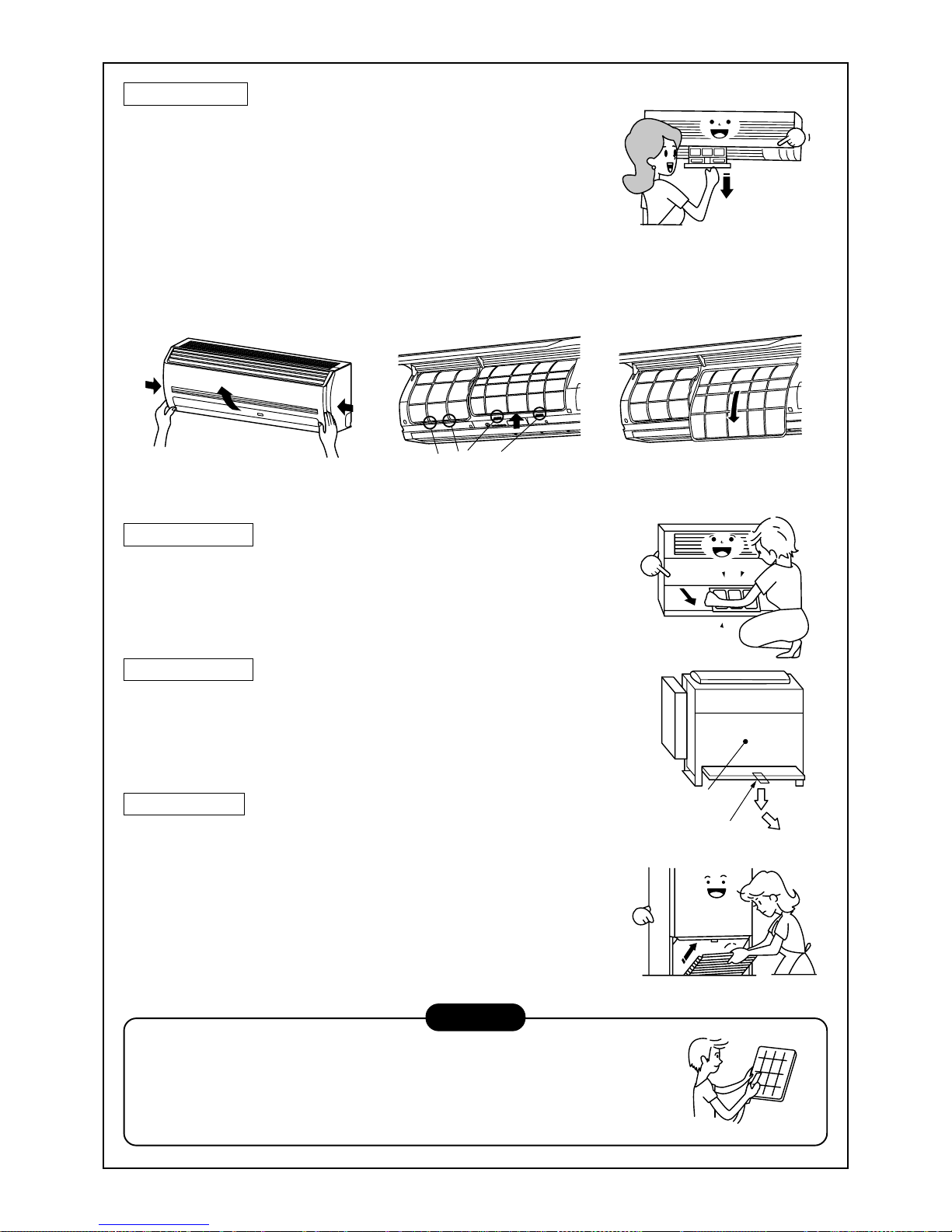
69
HINWEIS
• Verwenden Sie zur Reinigung des Filters einen Staubsauger oder eine Bürste.
Verwenden Sie bei starker Verschmutzung lauwarmes Wasser mit einem neutralen
Reinigungsmittel.
• Spülen Sie ihn nach dem Waschen gut aus und trocknen Sie ihn im Schatten.
• Setzen Sie den gereinigten Luftfilter wieder ein.
Drücken Sie gegen
den Filter und ziehen
ihn nach unten.
Frontverkleidung
(Unterteil)
Luftfilterarretierung
Filterhalterungen
Truhenmodell
• Drücken Sie leicht auf das Oberteil der Ansaugöffnung und ziehen es zu
sich hin.
• Nehmen Sie den Filter aus der Ansaugöffnung.
Einbaumodell
• Drücken Sie den Haken zur Befestigung des Luftfilters nach unten (unten
am Gerät).
• Schieben Sie den Filter zu sich hin und entfernen Sie ihn.
Standmodell
Aus-/Einbau des Luftfilters
• Ziehen Sie den Luftfilter zu sich hin.
• Um den Filter einzubauen, setzen Sie ihn ein und drücken ihn nach
innen.
Wand modell
(Modell: Serie 1H)
• Drücken Sie in die Mitte des Luftfilters. Die Klammer springt heraus.
• Lösen Sie den Luftfilter und ziehen ihn nach unten, während Sie gegen
das Gerät drücken.
(Modell: Serie 2H)
•Öffnen Sie das Abluftgitter.
Heben Sie das Abluftgitter in horizontale Position.
• Halten Sie den rechten und linken Feststellhebel des Filters und
schieben Sie sie leicht nach oben. Dann ziehen sie den Filter nach
außen vom Filterhalter weg.

70
Einbau des Luftfilters
• Setzen Sie den oberen Teil des Luftfilters ein, indem Sie die linke und rechte Kante zur Inneneinheit ausrichten,
bis sie sich in der korrekten Position befinden.
• Schließen Sie das Luftgitter wieder.
Leuchtet die FILTER-Anzeige auf der Inneneinheit, drücken Sie FILTER auf der Fernbedienung oder die TEM-
PORARY (TEMPORÄR) -Taste der Inneneinheit, um die Anzeige abzuschalten.
Filterhalterungen
Nicht verwenden.
Scheuerpulver
Benzin
Verdünner
Chemisch
behandelte
Reinigungstücher
Reinigen des Zuluftgitters
1. Ausbauen des Zuluftgitters
Halten Sie beide Seiten des Zuluftgitters und öffnen es nach oben.
Schieben Sie den Hebel nach links und nehmen das Gitter ab.
2. Wischen sie es mit einem weichen in Wasser getränkten Tuch
oder Schwamm ab.
(Verwenden Sie keine Metallbürste oder eine andere harte
Bürste.)
• Solche Bürsten verursachen Kratzer auf der Oberfläche des
Gitters und können die Beschichtung beschädigen.
• Wenn es sehr verschmutzt ist, verwenden Sie einen neutralen
Reiniger und spülen es, nachdem Sie das Zuluftgitter gereinigt
haben, mit Wasser wieder ab.
3. Wischen Sie das Wasser ab und lassen das Zuluftgitter trocknen.
4. Drücken Sie die linke und rechte Aufhängung des Zuluftgitters auf
die Bolzen am Klimagerät und drücken dann das Gitter fest auf.
Danach schieben Sie den Hebel wieder in die ursprüngliche
Position.
5. Vergewissern Sie sich, dass der Hebel eingerastet und das
Zuluftgitter fest verankert ist.
• Drücken Sie auf die vier mit Pfeilen gekennzeichneten
Positionen unten am Zuluftgitter, um sicher zu gehen, dass das
Gitter vollständig geschlossen ist.
Säuberung des Innengeräts und der Fernbedienung
VORSICHT
• Verwenden Sie ein weiches, trockenes Tuch.
• Ist die Raumeinheit stark verschmutzt, kann ein mit kaltem
Wasser angefeuchtetes Tuch verwendet werden.
• Verwenden Sie zur Reinigung der Fernbedienung nie ein
feuchtes Tuch.
• Verwenden Sie kein chemisch behandeltes Wischtuch.
Lassen Sie Reinigungsmittel nie länger auf die Oberfläche
des Geräts einwirken.
Dies kann zu Beschädigungen oder Ausbleichungen
führen.
• Verwenden Sie zum Säubern weder Benzin, noch
Verdünner, Poliermittel oder ähnliche Lösungsmittel.
Sie können die Kunststoffoberfläche beschädigen oder
verformen.

71
HINWEIS
Setzen Sie das Klimagerät regelmäßig ein, sind Reinigung und Wartung der Außen- und Raumeinheit
unbedingt erforderlich.
Wenn Ihr Klimagerät etwa acht Stunden täglich betrieben wird, müssen die Außen- und Raumeinheit
mindestens einmal in DREI MONATEN gereinigt werden. Reinigung und Wartung sollte durch einen
qualifizierten T echniker erfolgen.
Werden Innen- und Außengerät nicht regelmäßig gereinigt, hat dies eine schwache Kühlleistung, Vereisung,
Kondenswasserbildung und vorzeitiges Versagen des Kompressors zur Folge.
Falls Sie das Klimagerät für mindestens einen
Monat nicht benutzen,
1. Schalten Sie den Lüfter etwa 3 bis 4 Stunden ein, um das Innere
des Geräts zu trocknen
• Schalten Sie das Gerät in den FAN-(Lüfter)-Modus.
2. Stoppen Sie danach das Klimagerät und schalten Sie es mit dem
Hauptschalter oder der Sicherung aus.
Tests vor der Inbetriebnahme
1. Prüfen Sie, ob alle Luftfilter installiert sind.
2. Stellen Sie sicher, dass Zuluft- und Abluftöffnungen nicht verstopft
sind.
3. Schalten Sie den Hauptschalter oder die Sicherung der
Hauptstromversorgung ein, um das Klimagerät mit Strom zu
versorgen.
HINWEISE ZUM WIRTSCHAFTLICHEN BETRIEB DES KLIMAGERÄTS
Regelt Sie die Raumtemperatur auf ein angenehmes Niveau.
Säubern Sie die Luftfilter regelmäßig.
Sind die Luftfilter verstopft, reduziert sich die Leistung des Geräts.
Öffnen Sie Türen und Fenster nicht öfter als nötig.
Um die Raumtemperatur konstant zu halten, öffnen Sie Türen und Fenster nicht öfter als nötig.
Fenstervorhänge
Schließen Sie die Vorhänge beim Kühlen, um eine direkte Sonneneinstrahlung zu verhindern.
Schließen Sie die Vorhänge beim Heizen, um den Wärmeverlust zu reduzieren.
Sorgen Sie für eine gleichmäßige Zirkulation der Raumluft
Stellen Sie die Lüftungsgitter so ein, dass die Raumluft gleichmäßig zirkuliert.
Verwenden Sie ein
weiches, trockenes Tuch.
Erst trocknen,
wenn für längere
Zeit nicht benutzt.
Regeln
Huch, kühl hier!
Bitte säubern.
Bitte schlie
ßen
Bläst nach oben
Bläst nach unten
Einstellung des Luftstroms
Kühle und
trockene
Luft
Warme
Luft

72
WARNUNG
Schalten Sie die Stromzufuhr 12 Stunden
vor Inbetriebnahme ein.
FUNKTIONEN UND LEISTUNG DES KLIMAGERÄTS
Tests vor der Inbetriebnahme
• Prüfen Sie, ob das Erdungskabel korrekt angeschlossen ist.
• Prüfen Sie, ob der Luftfilter in der Inneneinheit installiert ist.
Heizbetrieb (nur bei Modellen mit integrierter Heizung)
• Zur Heizung wird eine Wärmepumpe, die Außenluft ansaugt
und warme Luft in den Raum bläst verwendet.
Sinkt die Temperatur der Außenluft, verringert sich die Heizleistung.
• Bei niedrigen Außentemperaturen ist daher eine zusätzliche Heizquelle zu empfehlen.
Abtauung im Heizbetrieb (nur bei Modellen mit integrierter Heizung)
• Bildet sich während des Heizbetriebs Eis auf dem Wärmetauscher der Außeneinheit, wechselt das System
automatisch in den Abtaumodus (für etwa 2 bis 10 Minuten), um eine konstante Heizleistung zu gewährleisten.
• Während des Abtauens stoppen die Ventilatoren von Innen- und Außeneinheit.
3-Minuten-Schutz
• Die Außeneinheit arbeitet, wenn das Gerät abgeschaltet und sofort neu gestartet wird, erst wieder nach etwa 3
Minuten. Hierdurch wird das System geschützt.
Stromausfall
• Kommt es während des Betriebs zu einem Stromausfall, stoppen alle Geräte.
• Drücken Sie zum Neustart des System die Taste ON/OFF (EIN/AUS).
Lüfterdrehung bei angehaltenen Geräten.
• Ist eine Inneneinheit auf Standby geschaltet und arbeiten die anderen Innengeräte weiter, dreht sich der Lüfter
des angehaltenen Geräts zum Schutz 1-mal pro Stunde für einige Minuten.
Sicherheitseinrichtung (Hochdruckschalter)
Der Hochdruckschalter stoppt das Klimagerät automatisch, wenn es überlastet wird.
Hierbei leuchtet die Betriebsanzeige weiter, das Gerät stoppt jedoch.
Hat sich die Sicherheitseinrichtung eingeschaltet, blinkt auf der Anzeige der Fernbedienung das Zeichen “
”.
Die Sicherheitseinrichtung schaltet sich in den folgenden Fällen ein:
Im Kühlbetrieb
• Wenn Zu- oder Abluftöffnung der Außeneinheit geschlossen sind.
• Wenn für längere Zeit starker Wind gegen die Abluftöffnung der Außeneinheit bläst.
Im Heizbetrieb (nur bei Modellen mit integrierter Heizung)
• Wenn der Filter der Inneneinheit mit Staub oder Schmutz verstopft ist.
• Wenn die Abluftöffnung der Inneneinheit verschlossen ist.
Kühl-/Heizbetrieb bei MiNi-SMMS
Bei MiNi-SMMS kann jede Inneneinheit einzeln gesteuert werden.
Es ist jedoch nicht möglich, dass Inneneinheiten, die an eine Außeneinheit angeschlossen sind, gleichzeitig in
unterschiedlichen Betriebsarten arbeiten.
Soll gleichzeitig ein Kühl- und Heizbetrieb durchgeführt werden, schaltet die Inneneinheit, die kühlt ab, und “
”
leuchtet auf.
Die Inneneinheit, die sich im Heizbetrieb befindet, arbeitet weiter.
Wurden die Geräte fest auf COLL (Kühlen) oder HEAT (Heizen) eingestellt, kann die jeweils andere Betriebsart
nicht ausgeführt werden.
Soll eine andere als die voreingestellte Betriebsart ausgeführt werden, erscheint “
” und das Gerät stoppt.
Charakteristik des Heizbetriebs (nur bei Modellen mit integrierter Heizung)
• Nach dem Start der Betriebsart wird nicht sofort warme Luft ausgeblasen. Nach 3 bis 5 Minuten (abhängig von
der Raum- oder Außentemperatur) hat sich der Wärmetauscher der Inneneinheit aufgewärmt und warme Luft
wird ausgeblasen.
• Steigt die Außentemperatur, kann die Außeneinheit während des Betriebs anhalten.
• Befinden sich andere Außengeräte im Heizbetrieb, kann der Lüfter zeitweilig stoppen, damit keine heiße Luft
ausgeblasen wird.

73
Kühlbetrieb
Heizbetrieb
Außentemperatur : –5°C bis 43°C (Trockentemp.)
Raumtemperatur : 21°C to 32°C (Trockentemp.), 15°C to 24°C (Nasstemp.)
VORSICHT
Relative Luftfeuchtigkeit im Raum weniger als 80 %.
Wird das Klimagerät bei höheren Werten betrieben, kann sich an der
Oberfläche Kondenswasser bilden.
Außentemperatur : –15°C bis 15.5°C (Nasstemp.)
Raumtemperatur : 15°C bis 28°C (Trockentemp.)
Betriebsbedingungen des Klimageräts
Um eine gute Leistung zu erzielen, betreiben Sie das Klimagerät unter folgenden Temperaturbedingungen:
Wird das Klimagerät außerhalb der oben beschriebenen Betriebsbedingungen gefahren, kann sich der
Sicherheitsschutz einschalten.
NEU-INSTALLATION
GEFAHR
Fragen Sie Ihren Fachhändler oder einen Installationsbetrieb, wenn Sie das Klimagerät neu installieren
oder an einem anderen Platz montieren möchten, und beachten Sie folgende Punkte.
Wurde das Klimagerät von Ihnen nicht fachgerecht installiert, kann dies zu einem Str omschlag führen
oder ein Feuer kann die Folge sein.
Installieren Sie das Klimagerät nicht an folgenden Orten
• Installieren Sie das Gerät nie in einem Abstand von einem Meter von Fernsehern, HiFi-Anlagen oder
Rundfunkempfängern. Wird das Gerät an solchen Stellen installier t, können Störungen, die vom Klimagerät
ausgehen, den Empfang der oben genannten Geräte behindern.
• Installieren Sie das Klimagerät nicht in der Nähe eines Geräts das mit hohen Frequenzen arbeitet (Nähmaschinen,
Massagegeräte usw.), da sonst die Funktion des Klimageräts gestört werden kann.
• Installieren Sie das Klimagerät nicht an einem feuchten oder öligen Ort, oder an Stellen, wo Dampf, Ruß oder
korrosive Gase entstehen.
• Installieren Sie das Klimagerät nicht an einem Ort mit star k salzhaltiger Luft, wie beispielsweise direkt an der Küste.
• Installieren Sie das Klimagerät nicht an einem Ort, an dem große Mengen Maschinenöl verwendet werden.
• Installieren Sie das Klimagerät nicht an einem Ort, an dem es ständig star kem Wind ausgesetzt ist, wie beispielsweise
an der Küste, auf dem Dach oder in einem oberen Stockwerk eines Gebäudes.
• Installieren Sie das Klimagerät nicht an einem Ort, an dem schwefelhaltige Gase austreten, wie beispielsweise in der
Nähe einer Heilquelle.
• Installieren Sie das Klimagerät nicht auf einem Schiff oder einem Mobilkran.
Achten Sie auf Geräusche und Vibrationen
• Installieren Sie das Klimagerät nicht an einem Ort, an dem der Geräuschpegel des Außengeräts oder die aus dem
Luftauslass strömende War mluft Ihre Nachbarn belästigen.
• Installieren Sie das Klimagerät immer auf einem soliden, stabilen Fundament, damit Betriebsgeräusche und
Vibrationen nicht nach außen übertragen werden.
• Wird nur ein einzelnes Innengerät betrieben, können an anderen Innengeräten, die zu der Zeit nicht in Betrieb sind,
Geräusche hörbar sein.
Lüftungsschlitze
Die Schlitze auf der Seite der Außeneinheit dienen als
Lüftungsschlitze zur Kühlung elektrischer Teile.
Wenn diese Schlitze verstopfen, kann es zu Problemen
mit diesen Teilen kommen. Achten Sie darauf, dass die
Schlitze nie verschlossen werden oder der Luftstrom
durch Hindernisse gestört wird.

74
VORGEHENSWEISE BEI FOLGENDEN SYMPTOMEN
Prüfen Sie die folgenden Punkte, ehe Sie sich an den Kundendienst wenden.
Dies ist kein Fehler.
Nochmals prüfen
Symptom
Außeneinheit
Inneneinheit
• Kalte, neblige Luft oder
Wasser strömen aus.
• Manchmal ist ein Zischen
zu hören.
• Manchmal ist ein Zischen
zu hören.
• Aus einer abgeschalteten
Inneneinheit des gleichen
Kühlkreises entweichen
Dampf und kalte Luft, oder
Sie hören Geräusche.
• Manchmal ist ein Zischen
zu hören.
• Die Zuluft riecht
•“
” leuchtet
• Wir die Stromzufuhr des
Klimageräts eingeschaltet,
ist ein klicken zu hören.
Startet oder stoppt automatisch
Arbeitet nicht
Luft ist nicht ausreichend kalt oder warm
Ursache
• Lüfter der Außeneinheit stoppt automatisch und Abtauung
wird durchgeführt.
• Magnetventil arbeitet, wenn die Abtauung beginnt oder
beendet wird.
• Bei Betriebsbeginn, während des Betr iebs oder direkt nach
Ende des Betriebs kann ein Geräusch wie fließendes Wasser
gehört werden und die Betriebsgeräusche können für 2 bis 3
Minuten nach dem Start ansteigen. Es handelt sich um
Flussgeräusche von Kältemittel oder Kondensat des
Entfeuchters.
• Wenn das Klimasystem arbeitet, fließt durch eine angehaltene
Inneneinheit des Kühlkreises noch Kältemittel, damit sich kein
Öl oder Kältemittel ansammeln kann.
Daher hören Sie evtl. Strömungsgeräusche oder es kann,
wenn andere Inneneinheiten im Heizbetrieb arbeiten, weißer
Dampf oder im Kühlbetrieb kalte Luft entweichen.
• Dieses Geräusch entsteht, wenn sich der Wärmetauscher
aufgrund von Temperaturänderungen leicht ausdehnt oder
zusammenzieht.
• Unterschiedliche Gerüche von Wänden, Teppichen,
Zigaretten, Kleidung oder Kosmetik können Sich im
Klimagerät ansammeln.
• Kühlbetrieb kann nicht durchgeführt werden, weil sich eine
andere Inneneinheit im Heizbetrieb befindet.
• Wenn das Klimagerät fest auf COOL (Kühlen) oder HEAT
(Heizen) eingestellt wurde und eine andere Betriebsart
ausgeführt werden soll.
• Wenn der Lüfter stoppt, damit keine heiße Luft eingeblasen
wird.
• Das Geräusch ertönt, wenn der Strom eingeschaltet ist und
sich das Expansionsventil öffnet.
• Ist die Zeitschaltuhr “ON (AN)” oder “OFF (AUS)”?
• Ist die Stromversorgung ausgefallen?
• Ist der Hauptschalter ausgeschaltet?
• Ist die Hauptsicherung durchgebrannt?
• Hat sich die Schutzeinrichtung eingeschaltet?
(Die Kontrollleuchte schaltet ein)
• Ist die Zeitschaltuhr “ON (AN)”?
(Die Kontrollleuchte schaltet ein)
• Wurde gleichzeitig COOL (Kühlen) und HEAT (Heizen)
ausgewählt.
(In der Anzeige der Fernbedienung erscheint “
”.)
• Ist Zu- oder Abluftöffnung der Außeneinheit verschlossen?
• Sind Türen oder Fenster geöffnet?
• Ist der Luftfilter mit Staub verstopft?
• Befindet sich die Lüftungsklappe der Inneneinheit in der
richtigen Stellung?
• Wurde die Lüftungsleistung auf “LOW (Niedrig)” oder “MED
(Mittel)” eingestellt und als Modus “FAN (Lüfter)” gewählt?
• Ist die Temperatureinstellung angemessen?
• Wurde gleichzeitig COOL (Kühlen) und HEAT (Heizen)
ausgewählt?
(In der Anzeige der Fernbedienung erscheint“
”.)
Kommt es zu einem der folgenden Fehler, schalten Sie das Gerät und die Stromversorgung sofort aus und nehmen
Sie Kontakt mit Ihrem Händler auf.
• Die Funktion des Schalters ist nicht in Ordnung.
• Die Sicherung brennt häufig durch oder die Sicherung springt oft heraus.
• Fremdkörper oder Wasser sind in das System eingedrungen
• Obwohl die Ursache für die Aktivierung der Schutzvorrichtung beseitigt wurde, läßt sich das System nicht mehr in
Betrieb nehmen.
• Andere unübliche Probleme.
Kein Ger
äusch
Komisch

75
Vorgehensweise
1
2
3
Beschreibung
Wenn Sie gleichzeitig
SET
und
TEST
für 4 Sekunden oder
länger drücken, erscheint die rechts stehende Anzeige:
Wird [Service Check] angezeigt, wechselt die
Fernbedienung in die Fehlertabelle.
• [01: Reihenfolge der Fehler] wird im Fenster CODE NO.
angezeigt.
• [Kennziffer] wird im Fenster [CHECK] angezeigt.
• [Die Nummer der fehlerhaften Raumeinheit] erscheint
unter UNIT NO.
Jedesmal, wenn Sie die Tasten , drücken, wechseln Sie zum nächsten Fehler im
Speicher.
Die Zahlen unter CODE NO. zeigen den letzten [01] bis zum ältesten [04] Fehler an.
VORSICHT
Drücken Sie nicht die Taste CL, da Sie dann den Fehlerspeicher löschen.
Um den Fehlerspeicher zu verlassen, drücken Sie auf die Taste
TEST
.
Bestätigung und Prüfung
Tritt ein Fehler auf, erscheint in der Anzeige der
Fernbedienung eine entsprechende Kennziffer und die
Nummer der betroffenen Raumeinheit.
Die Kennziffer wird nur während des Betriebs
angezeigt.
Erlischt die Anzeige, gehen Sie wie in dem Absatz
“Aufruf des Fehlerspeichers” beschrieben vor.
Aufruf des Fehlerspeichers
Tritt ein Fehler auf, kann der Fehlerspeicher wie im
folgenden beschrieben aufgerufen werden.
(Es können bis zu 4 Fehler gespeichert werden.)
Der Fehlerspeicher kann während des Betriebs oder,
wenn das System angehalten wurde, aufgerufen
werden.
1. Prüfen Sie die Fehler wie oben beschrieben.
2. Zur Reparatur oder Wartung des Klimagerätes wenden Sie sich an einen autorisierten Händler oder einen
qualifizierten Installateur.
3. Details zu den Kennziffern der Fehler finden Sie im Servicehandbuch.
Prüfcode Nr. der fehlerhaften
Raumeinheit
CODE No.
UNIT No.
R.C. No.
3
2
1
ON / OFF
FAN
TEMP.
SWING/FIXTIME
MODE
VENT
UNITSET CL
FILTER
RESET
TEST
TIMER SET
CODE No.
UNIT No.
R.C. No.

76
PRECAUZIONI PER LA SICUREZZA
ATTENZIONE
Avviso per l’installazione
Affidare il lavoro di installazione al rivenditore o a un negoziante
specializzato.
Per eseguire il lavoro di installazione sono necessarie una conoscenza e una
tecnologia specifiche.
Non eseguire l’installazione personalmente. Se si esegue un’installazione incompleta,
si possono provocare incendi, folgorazioni, ferite o perdite d’acqua.
Usare solo i prodotti, in vendita a parte, specificati dalla nostra azienda.
Per i prodotti in vendita a parte, si raccomanda di usare quelli specificati dalla nostra
azienda. Altrimenti, si possono provocare incendi, folgorazioni o perdite d’acqua.
Affidare il lavoro di installazione a un tecnico specializzato.
Se si installano le unità in un locale piccolo, prendere le misure necessarie
affinché, in caso di perdite, il refrigerante non superi la concentrazione critica.
AVVERTENZA
Per quanto riguarda le contromisure contro la concentrazione critica, eseguire il lavoro di installazione con la
consulenza del rivenditore. Se si verificano perdite del refrigerante e viene superata la concentrazione critica,
si può causare una deficienza di ossigeno.
Controllare se la messa a terra è stata eseguita correttamente.
La messa a terra è necessaria. Se la messa a terra è incompleta, si possono provocare folgorazioni.
(Per ulteriori dettagli, conformarsi alle normative locali).
Avviso per l’uso
Non esporre direttamente il corpo all’aria fredda per lungo tempo, e non
rinfrescarsi eccessivamente.
Ciò potrebbe provocare un peggioramento delle condizioni fisiche o problemi di salute.
Non inserire mai le dita o una barra nella porta di ingresso o in quella di
uscita dell’aria.
Poiché all’interno dell’unità la ventola ruota a velocità elevata, si possono provocare
ferite.
Quando si percepisce un problema (odore di bruciato, ecc.), arrestare il
funzionamento, spegnere l’interruttore di alimentazione e contattare il
rivenditore dal quale si è acquistato il condizionatore d’aria.
Se si mantiene in funzione il condizionatore d’aria guasto, si possono provocare
incendi, folgorazioni o problemi.
Avviso per spostamenti/riparazioni
Non modificare mai il condizionatore d’aria.
Si possono provocare incendi o folgorazioni.
Per quanto riguarda le riparazioni, farle eseguire al rivenditore dal quale si è
acquistato il condizionatore d’aria
Se si eseguono riparazioni incomplete, si possono provocare incendi o folgorazioni.
Quando si desidera spostare o reinstallare il condizionatore d’aria, contattare
il rivenditore dal quale si è acquistato o un tecnico specializzato.
Se si esegue un’installazione incompleta, si possono provocare incendi, folgorazioni,
ferite o perdite d’acqua.
ITALIANO

77
AVVERTENZA
Avvertenza per l’installazione
Controllare che siano installati i tubi di scarico, in modo che sia
possibile scaricare l’acqua in sicurezza.
Se la tubazione è incompleta, si possono verificare delle perdite, che
causerebbero umidità ai mobili.
Controllare che sia installato l’interruttore per dispersioni a terra.
È necessario montare un interruttore per dispersioni a terra.
Altrimenti, si possono provocare folgorazioni.
Controllare che il condizionatore d’aria sia installato in un luogo in cui
non si verifichino perdite di gas infiammabili.
Se si verifica una perdita e il gas si accumula intorno all’unità, si può provocare
un incendio.
Controllare che l’unità esterna sia fissata sulla base.
Se non è fissata saldamente sulla base, si possono provocare incidenti, come la
caduta del condizionatore.
Metodo di esecuzione dei controlli
Non pulire il condizionatore d’aria con acqua.
Si possono provocare folgorazioni.
Non posizionare apparecchi che usano combustibili in un punto sul
quale soffia direttamente l’aria del condizionatore.
Si può provocare una combustione non corretta del combustibile.
Quando si usa il condizionatore d’aria insieme ad apparecchi che
usano combustibili, ventilare con cura il locale.
Se la ventilazione è incompleta, si può provocare una carenza di ossigeno.
Controllare che la piastra di installazione, ecc. non sia danneggiata
dall’uso prolungato.
Se la piastra è danneggiata, l’unità potrebbe cadere, provocando ferite.
Non posizionare piante e animali in un punto sul quale soffia
direttamente l’aria del condizionatore.
Si possono provocare problemi alle piante o agli animali.
Non posizionare spray infiammabili, ecc. accanto al condizionatore
d’aria e non spruzzare direttamente sostanze sul condizionatore.
Si possono provocare incendi.
Non appoggiare sull’unità recipienti contenenti acqua, come, ad
esempio, v asi.
Nell’unità penetrerebbe umidità, gli isolamenti elettrici si deteriorerebbero e si
potrebbero provocare folgorazioni.
Non maneggiare gli interruttori con le mani bagnate.
Si possono provocare folgorazioni.
Non utilizzare il condizionatore d’aria per scopi particolari, come
conservazione di cibi, piante e animali, utensili di precisione e opere
d’arte.
Si può provocare un deterioramento della qualità.

78
Scarico a 2 vie/scarico a 3 vie
È possibile selezionare lo scarico a 2 o 3 vie, in
base alla forma o alla disposizione del locale.
Per ulteriori dettagli, consultare il rivenditore dal
quale si è acquistato il condizionatore d’aria.
Uscita dell’aria/
deflettore per l’uscita dell’aria
Selezionare la direzione del flusso dell’aria
durante il raffreddamento o il riscaldamento.
Vite di messa a terra
È inclusa nella scatola dei
componenti elettrici.
Filtro dell’aria
Rimuove polvere e sporcizia.
(Il filtro dell’aria si trova nella
griglia per l’aria).
Fermaglio
Questo fermaglio serve per
aprire/chiudere la griglia di ingresso dell’aria.
Griglia di ingresso dell’aria
Da qui viene aspirata l’aria contenuta nel locale.
Vite di messa a terra
È inclusa nella scatola dei
componenti elettrici.
Uscita dell’aria/deflettore per l’uscita dell’aria
Selezionare la direzione del flusso dell’aria durante
il raffreddamento o il riscaldamento.
Filtro dell’aria
Rimuove polvere e sporcizia.
(Il filtro dell’aria si trova nella
griglia per l’aria).
Fermaglio
Questo fermaglio serve per
aprire/chiudere la griglia di ingresso dell’aria.
Griglia di ingresso dell’aria
Da qui viene aspirata l’aria contenuta nel locale.
Ingressi dell’aria
Da qui viene aspirata l’aria
contenuta nel locale.
Filtro dell’aria
Rimuove polvere e sporcizia.
(Il filtro dell’aria si trova nel pannello centrale).
Vite di messa a terra
È inclusa nella scatola dei
componenti elettrici.
Pannello centrale
Uscita dell’aria/deflettore per l’uscita dell’aria
Selezionare la direzione del flusso dell’aria
durante il raffreddamento o il riscaldamento.
Unità interna
[Tipo a cassetta con scarico d’aria a 4 vie]
Da MMU-AP0091H, AP0121H, AP0151H, AP0181H, AP0241H,
MMU-AP0271H, AP0301H, AP0361H, AP0481H, AP0561H
[Tipo a cassetta con scarico d’aria a 2 vie]
Ingressi dell’aria
Sono situati sui lati anteriore,
posteriore, sinistro e destro.
Base di fissaggio
Uscita dell’aria (scarico)
Quando si esegue il raffreddamento, viene scaricata l’aria calda.
Quando si esegue il riscaldamento, viene scaricata l’aria fredda.
Foro per l’alimentazione
Foro di connessione della
tubazione del refrigerante
All’interno è inclusa la valvola
di connessione.
Unità esterna
Da MMU-AP0071MH, AP0091MH, AP0121MH, AP0151MH, AP0181MH
NOME DI OGNI PARTE
Parti da acquistare separatamente
Telecomando via ca vo
RBC-AMT31E
Telecomando via cavo, semplice
RBC-AS21E2
Kit del telecomando via radio
TCB-AX21E2 RBC-AX22CE2 RBC-AX21U(W)-E2
ON / OFF
FAN
TEMP.
SWING/FIXTIME
MODE
VENT
UNITSET CL
FILTER
RESET
TEST
TIMER SET
CODE No.
UNIT No.
TEST
SETTING
DATA
SET
R.C. No.
H
˚C
TEST
SETTING

79
Timer settimanale
RBC-EXW21E2
Telecomando centrale
TCB-SC642TLE2
WEEKLY TIMER
ERROR
SuMoTuWeTh FrSa
PROGRAM1
PROGRAM2
PROGRAM3
SELECT ZONE
CL
SET
GROUP
CODE
No.
UNIT No.
No.
R.C.
TEST
ZONE
ALL
ZONE
GROUP
SETTING
1234
SET DATA
Vite di messa a terra
È inclusa nella scatola
dei componenti elettrici.
Uscita dell’aria/
deflettore per l’uscita dell’aria
Selezionare la direzione del flusso dell’aria
durante il raffreddamento o il riscaldamento.
Griglia di ingresso dell’aria
Da qui viene aspirata l’aria
contenuta nel locale.
Filtro dell’aria
Rimuove polvere e sporcizia.
(Il filtro dell’aria si trova nella griglia per l’aria).
[Tipo a cassetta con scarico d’aria a 1 vie]
Da MMU-AP0071YH a AP0121YH
Da MMU-AP0152SH, AP0182SH, AP0242SH
Tasto
Tasto per aprire/chiudere
la porta di aspirazione
Uscita dell’aria/deflettore per l’uscita dell’aria
Cambiare la direzione dell’aria da scaricare in
base alla modalità di raffreddamento/riscaldamento.
Filtro dell’aria
Rimuove la polvere o la sporcizia.
(Si trova sulla porta di aspirazione).
Porta d’aspirazione
Aspira da quì l’aria interna al locale.
Filtro dell’aria
Rimuove la polvere o la sporcizia.
(Si trova sulla porta di aspirazione).
Vite di messa a terra
È inclusa nella scatola dei componenti elettrici.
[Tipo standard a condotto nascosto]
[Condotto nascosto del tipo ad alta pressione statica]
[Tipo a Condotto Sottile]
Ingressi dell’aria
Da qui viene aspirata l’aria contenuta
nel locale.
Vite di messa a terra
Le viti di messa a terra si
trovano nella scatola dei
componenti elettrici.
Flangia dell’uscita dell’aria
Viene collegato il condotto
di scarico.
Filtro dell’aria
Rimuove polvere e sporcizia.
(Il filtro dell’aria si trova nella griglia di ingresso dell’aria).
Uscita dell’aria
Viene collegato il condotto
di scarico.
Ingressi dell’aria
Viene collegato il condotto
di aspirazione.
Vite di messa a terra
Le viti di messa a terra si trovano
nella scatola dei componenti elettrici.
Vaschetta di scarico
Ingressi dell’aria
Viene collegato il
condotto di aspirazione.
Filtro dell’aria
(Il filtro dell’aria non è
equipaggiato su tutti I
modleli della serie.)
Vite di messa a terra
È inclusa nella scatola
dei componenti elettrici.
Uscita dell’aria
Viene collegato il
condotto di scarico.

80
[Tipo da installare al soffitto]
[Tipo per mura alte]
Da MMK-AP0071H a AP0241H
Da MMK-AP0072H a AP0122H
Griglia di ingresso dell’aria
Da qui viene aspirata l’aria
contenuta nel locale.
Vite di messa a terra
Le viti di messa a terra si trovano nella scatola dei
componenti elettrici.
Filtro dell’aria
Rimuove polvere e sporcizia.
(Il filtro dell’aria si trova nella
griglia di ingresso dell’aria).
Uscita dell’aria/deflettore per l’uscita dell’aria
Cambiare la direzione dell’aria da scaricare in base
alla modalità di raffreddamento/riscaldamento.
Tasto
Tasto per aprire/chiudere
la porta di aspirazione
Filtro dell’aria
Rimuove la polvere o la sporcizia.
(Si trova sulla porta di aspirazione).
Porta di ingresso dell’aria
Da questa porta viene aspirata l’aria contenuta nel
locale.
Vite di messa a terra
Le viti di messa a terra si trovano nella scatola dei
componenti elettrici.
Uscita dell’aria/deflettore per l’uscita dell’aria
Cambiare la direzione dell’aria da scaricare in
base alla modalità di raffreddamento/riscaldamento.
Griglia di ingresso dell’aria
Da qui viene aspirata l’aria contenuta
nel locale.
Vite di messa a terra
Le viti di messa a terra si trovano nella scatola dei
componenti elettrici.
Filtro dell’aria
Rimuove polvere e sporcizia.
(Il filtro dell’aria si trova nella
griglia di ingresso dell’aria).
Uscita dell’aria/deflettore per l’uscita dell’aria
Cambiare la direzione dell’aria da scaricare in base
alla modalità di raffreddamento/riscaldamento.
[Tipo ad armadietto da
posizionare sul pavimento]
[Tipo nascosto da posizionare
sul pavimento]
[Tipo da posizionare sul pavimento]
Uscita dell’aria/deflettore per l’uscita dell’aria
Scambia la direzione dell’aria in base al tempo di
raffreddamento o riscaldamento.
Vite di messa a terra
È inclusa nella scatola dei
componenti elettrici.
Porta di ingresso dell’aria
Da qui viene aspirata l’aria contenuta nel locale.
Filtro dell’aria
Rimuove la sporcizia o la polvere.
(Si trova nella porta di aspirazione).
Porta di uscita dell’aria
Vaschetta di scarico (con filtro di scarico)
Questo accessorio viene installato a livello locale.
Filtro dell’aria
Rimuove la sporcizia o la polvere.
(Si trova nella porta di aspirazione).
Porta di ingresso dell’aria
Da qui viene aspirata l’aria contenuta nel locale.
Vite di messa a terra
È inclusa nella scatola dei componenti elettrici.
Pannello anteriore (Lato inferiore)
Supporto in metallo per il fissaggio
Deflettore verticale
È possibile scaricare automaticamente l’aria verso
destra/verso sinistra in momenti predefiniti.
Deflettore orizzontale/porta di uscita dell’aria
Scambia la direzione dell’aria in base al tempo di
raffreddamento o riscaldamento.
Vite di messa a terra
È inclusa nella scatola dei componenti elettrici.
Porta di ingresso dell’aria
Da qui viene aspirata l’aria contenuta nel locale.
Filtro dell’aria
Rimuove la sporcizia o la polvere.
Vaschetta di scarico
L’acqua accumulata nella vaschetta di scarico viene
scaricata da qui attraverso il tubo di scarico.
Supporto in metallo per il fissaggio
(destro e sinistro)

81
Sezione
del display
Sezione
operazioni
ON / OFF
FAN
TEMP .
SWING/FIXTIME
MODE
VENT
UNITSET CL
FILTER
RESET
TEST
TIMER SET
CODE No.
UNIT No.
TEST
SETTING
DATA
SET
R.C. No.
H
2
15
5
78 9
3
1
4
6
10
11
13
16
12
14
17
CODE No.
UNIT No.
TEST
SETTING
DATA
SET
R.C. No.
H
NOME DELLE PARTI DEL TELECOMANDO
Sezione del display
Tutte le voci del display riportate nella figura di destra servono solo per le
spiegazioni. Durante il funzionamento effettivo vengono visualizzate solo
le voci selezionate. In realtà sono visualizzati solo i contenuti selezionati.
• Quando si spegne per la prima volta l'interruttore di rilevamento delle
perdite, sulla parte del display del telecomando lampeggia l'indicazione
[SET DATA]. Mentre il display lampeggia, viene confermato
automaticamente il modello. Quindi, dopo che l'indicazione [SET DATA]
è scomparsa attendere un poco e poi utilizzare il telecomando.
1
Indicazione SET DATA (DATI IMPOSTATI)
Visualizzata durante l'impostazione del timer.
2
Display della modalità operativa
Viene visualizzata la modalità di funzionamento
selezionata.
3
Indicazione CHECK (CONTROLLO)
Visualizzata quando il dispositivo di protezione è in
funzione o quando si verifica un problema.
4
Indicazione del tempo del timer.
Viene visualizzato il tempo impostato per il timer.
(Se si verifica un problema, viene visualizzato il codice di
controllo).
5
Indicazione dell'impostazione SETIN del timer
Quando si preme il tasto SETIN del timer, viene
selezionato il display del timer nell'ordine [OFF] →
[OFF] ripetizione spegnimento timer (OFF)
→
[ON]
→ Assenza del display.
6
Indicazione del filtro
Se viene visualizzata l'indicazione “FILTER
”, pulire il
filtro dell'aria.
7
Indicazione del funzionamento di prova (TEST)
Visualizzata durante il funzionamento di prova.
8
Display della posizione del deflettore
[Solo per il tipo con cassetta di scarico dell’aria a 4
vie e per il tipo da installare al soffitto]
Visualizza la posizione del deflettore
9
Indicazione SWING (OSCILLAZIONE)
Visualizzata durante il movimento verso l'alto/verso il
basso del deflettore.
10
Indicazione della temperatura impostata
Viene visualizzata la temperatura impostata
selezionata.
11
Indicazione del sensore del telecomando
Visualizzata quando viene usato il sensore del
telecomando.
12
Indicazione PRE-HEAT
Visualizzata quando viene avviato il funzionamento in
modalità di riscaldamento o in modalità di sbrinamento.
Quando viene visualizzata questa indicazione, la
ventola dell'unità interna si arresta oppure entra in
modalità LOW.
13
Display di pronto al funzionamento
(solo per i modelli con pompa per il calore)
Visualizzato quando il funzionamento di
raffreddamento o quello di riscaldamento
risulta impossibile in quanto il valore della
temperatura esterna non è compreso tra i
valori limite per il funzionamento.
14
Indicazione di assenza di funzioni
Visualizzata quando non viene eseguita
nessuna funzione, anche se si preme il tasto
corrispondente.
15
Display della modalità di ventilazione
Viene visualizzata la modalità di ventilazione
selezionata.
(AUTO)
(ALTA)
(MEDIA) (BASSA)
Nei modelli del tipo a condotto nascosto e ad
elevata pressione statica, viene solo
visualizzato [HIGH] per la velocità dell’aria.
16
Indicazione del comando di selezione della
modalità
Visualizzato allorché si preme il tasto
“Selezione della modalità di funzionamento
”
quando la modalità di funzionamento è stata
impostata su riscaldamento o raffreddamento
dal responsabile del sistema di
climatizzazione.
17
Indicazione di comando centralizzato
Indicazione visualizzata quando il telecomando
è utilizzato insieme al telecomando per
controllo centralizzato, ecc.
Se l’uso del telecomando non è consentito dal
controllo centralizzato, quando si usano i tasti
,
ON / OFF
,
MODE
, / lampeggia
e il cambiamento non è accettato.
(Le cose che possono essere impostate
usando il telecomando differiscono a seconda
della modalità di controllo centralizzato. Per
informazioni dettagliate, far riferimento al
manuale d’istruzioni per il telecomando di
controllo centralizzato.)

82
Sezione operazioni
Per selezionare l'operazione desiderata premere il tasto relativo.
Questo telecomando può controllare fino a un massimo di 8 unità interne.
•È necessario impostare i dettagli dell'operazione una sola volta, poi è possibile usare il condizionatore d'aria
semplicemente premendo il tasto
ON / OFF
.
1
Tasto di selezione del volume dell’aria
Seleziona la modalità desiderata per il volume
dell’aria.
Non è possibile controllare i modelli del tipo a
condotto nascosto e ad elevata pressione statica.
2
Tasto di impostazione del timer
Il tasto TIMER SET (IMPOSTAZIONE DEL
TIMER) viene usato quando si imposta il timer.
3
Tasto di controllo
Il tasto CHECK (CONTROLLO) viene usato per le
operazioni di controllo.
Durante il funzionamento normale, non utilizzare
questo tasto.
4
Tasto
VENT
Il tasto
VENT
viene usato quando si collega una
ventola disponibile sul mercato, ecc.
• Se quando si preme il tasto
VENT
sul
telecomando viene visualizzata l'indicazione
, non è collegata nessuna ventola.
5
Tasto di cancellazione dell'indicazione del
filtro
Ripristina (cancella) l'indicazione “FILTER
”.
6
Direzione del soffio d’aria e oscillazione
UNIT
: Se si controllano più unità interne con un
solo telecomando, quando si è regolata
la direzione dell’aria, selezionare le
unità.
SWING/FIX
: Impostare l’oscillazione e l’angolazione
automatiche del deflettore.
• Questa funzione non è disponibile nel tipo
standard con condotto nascosto, nel tipo ad
elevata pressione statica, nel tipo ad
armadietto da posizionare sul pavimento, nel
tipo nascosto da posizionare sul pavimento e
nel tipo a condotto sottile.
7
Spia di funzionamento
La spia è accesa durante il funzionamento. La
spia è spenta quando il condizionatore non è in
funzione.
Tuttavia, esso lampeggia quando è in funzione un
dispositivo di sicurezza o quando si verifica
un'anomalia.
8
T asto
ON / OFF
Quando si preme questo tasto, viene avviato il
funzionamento, che viene interrotto quando si
preme di nuovo il tasto.
Quando viene arrestato il funzionamento, la spia
di funzionamento e tutti i display vengono spenti.
9
Tasto di selezione della modalità di
funzionamento
Seleziona la modalità di funzionamento
desiderata.
10
Tasto di impostazione della temperatura
Regola la temperatura del locale.
IImpostare la temperatura desiderata premendo
o .
OPZIONE:
Sensore del telecomando
Normalmente il sensore TEMP. dell'unità interna rileva
la temperatura.
È anche possibile misurare la temperatura intorno al
telecomando.
Per ulteriori dettagli, contattare il rivenditore dal quale
si è acquistato il condizionatore d'aria.
• Nel caso si controllino più unità interne con un solo
telecomando, nel controllo di gruppo non è
disponibile l’operazione di impostazione.
1
7
3
5
2
8
9
6
4
10
ON / OFF
FAN
TEMP.
SWING/FIXTIME
MODE
VENT
UNITSET CL
FIL TER
RESET
TEST
TIMER SET

83
USO CORRETTO
Quando si usa il condizionatore d'aria per la prima volta o quando si modificano i valori memorizzati in SET DATA,
seguire la procedura indicata qui sotto.
La volta successiva, premendo il tasto
ON / OFF
verrà avviato il funzionamento nello stato già impostato.
Preparazione
Accendere l'interruttore principale e/o l'interruttore di rilevamento delle perdite.
• Quando si accende l'alimentazione, sul telecomando si accende la sezione del display.
* Dopo che si è accesa l'alimentazione, il telecomando non accetta nessuna operazione per circa 1 minuto, ma
questo non costituisce un malfunzionamento.
REQUISITI
• Quando si usa il condizionatore d’aria, azionarlo solo con il tasto
ON / OFF
senza spegnere l’interruttore
principale di alimentazione e l’interruttore per dispersioni a terra.
• Durante l’uso del condizionatore d’aria, non spegnere l’interruttore per dispersioni a terra.
• Dopo che il condizionatore d’aria è stato spento per lungo tempo, accendere l’interruttore per dispersioni a
terra 12 o più ore prima di riavviarlo.
1
Premere il tasto
ON / OFF
.
Si accende la spia di funzionamento e si avvia il condizionatore.
2
Selezionare la modalità operativa con il tasto
MODE
.
A ogni pressione del tasto, il display cambia nell’ordine
mostrato a destra.
• La funzione “modalità DEUMIDIFICAZIONE
” non
è disponibile nel tipo ad alta pressione statica in
condotto nascosto.
3
Selezionare il volume dell'aria con il tasto
FAN
.
A ogni pressione del tasto, il display cambia nell'ordine
mostrato sulla destra.
• Quando il volume dell'aria è impostato su
“AUTO
”, il volume dell'aria cambia a secondo
della temperatura della stanza.
• In modalità DRY
, viene visualizzata l'indicazione “AUTO ” e il volume dell'aria viene impostato su
“LOW (BASSO)”.
• Nel funzionamento di riscaldamento, se la temperatura della stanza non è calda a sufficienza con la
modalità di riscaldamento impostata si “LOW
”, selezionare il funzionamento in modalità “MED. ” o
“HIGH
”.
• La temperatura rilevata dal sensore è quella accanto all’ingresso dell’aria dell’unità interna. Pertanto, essa
potrebbe essere leggermente diversa da quella del locale, a seconda dello stato dell’installazione. Il valore
di impostazione è il criterio sul quale è basata la temperatura del locale. (In modalità FAN non è possibile
selezionare la velocità automatica dell’aria).
• Nel “tipo con condotto nascosto e ad elevata pressione statica” non è presente la funzione di volume
dell’aria, ma viene visualizzata solo la velocità dell’aria “HIGH
”.
4
Determinare la temperatura impostata premendo il tasto “TEMP. ” o il tasto “TEMP. ”.
Arresto
Premere il tasto
ON / OFF
.
La spia di funzionamento si spegne e il condizionatore si arresta.
1
3
2
4
ON / OFF
FAN
TEMP.
SWING/FIXTIME
MODE
VENT
UNITSET CL
FILTER
RESET
TEST
TIMER SET
HEAT DRY COOL FAN
Modello con pompa per il calore
DRY COOL FAN
Modello solo per raffreddamento
(Deumidificazione)
LOW MED. HIGH
AUTO

84
REQUISITI
[Nel funzionamento di raffreddamento]
• Il funzionamento inizia dopo circa 1 minuto.
[Nel funzionamento di riscaldamento (solo per i modelli con pompa per il calore)]
• Nel riscaldamento, il funzionamento della ventola può continuare per circa 30 secondi dopo l’arresto del
condizionatore d’aria.
• In condizioni di arresto, la ventola interna continua il funzionamento di prer iscaldamento da 3 a 5 minuti e
poi emette l’aria. (Sul telecomando si accende il display
).
• Se la temperatura del locale ha raggiunto quella impostata e l’unità esterna si arresta, la velocità dell’aria
diventa molto bassa e il volume dell’aria viene estremamente diminuito.
• In modalità HEAT
, se la temperatura del locale raggiunge quella impostata, l’unità esterna si arresta, il
flusso dell’aria si abbassa (LOW) e il volume dell’aria diminuisce.
• In modalità di sbrinamento, la ventola si arresta, in modo che non venga scaricata aria fredda, e viene
visualizzato PRE-DEF.
.
REGOLAZIONE DELLA DIREZIONE DELL’ARIA
Per aumentare l’effetto del raffreddamento o del riscaldamento, durante il raffreddamento o il
riscaldamento usare il deflettore di scarico in direzioni diverse.
Per quanto riguarda le caratteristiche dell’aria, l’aria fredda si accumula sul lato inferiore e quella calda sul lato
superiore.
AVVERTENZA
Durante il raffreddamento, impostare la feritoia di scarico in orizzontale.
Se si esegue il raffreddamento con lo scarico rivolto verso il basso, la superficie della porta di scarico o la
feritoia di scarico vengono bagnate dalla condensa e si può verificare la caduta di gocce.
REQUISITI
• Se si esegue il riscaldamento con lo scarico in orizzontale, nel locale può aumentare la irregolarità della
temperatura.
Tipo a cassetta con scarico d’aria a 4 vie
• Quando il condizionatore d’aria si arresta, il deflettore di scarico si rivolge automaticamente verso il
basso.
• Quando il condizionatore d’aria è nello stato di pronto al
riscaldamento, il deflettore di scarico si riv olge ver so l’alto.
L’oscillazione inizia dopo la cancellazione dello stato di
pronto al riscaldamento ma, anche se lo stato è pronto al
funzionamento, sul telecomando viene visualizzato
“SWING ”.
[Nel funzionamento di raffreddamento]
Utilizzare il deflettore di scarico in orizzontale.
[Nel funzionamento di riscaldamento
(solo per i modelli con pompa per il calore)]
Utilizzare il deflettore di scarico rivolto verso il basso.

85
Come impostare la direzione dell’aria
Premere il tasto
SWING/FIX
.
1
A ogni pressione del tasto, la direzione dell’aria cambia.
Nel funzionamento di riscaldamento
Impostare il deflettore dell’uscita dell’aria verso il basso.
Se lo si rivolge verso l’alto, l’aria calda potrebbe non arrivare fino a terra.
Nel funzionamento di raffreddamento/deumidificazione
Impostare il deflettore dell’uscita dell’aria verso l’alto.
Se lo si rivolge verso il basso, sulla porta di scarico si depositerebbe
della condensa, che a sua volta farebbe cadere delle gocce.
Come avviare l’oscillazione
2
Premere il tasto
SWING/FIX
.
Impostare la direzione del deflettore dell’uscita
dell’aria nella posizione più bassa e poi premere
di nuovo il tasto
SWING/FIX
.
• Viene visualizzato [SWING
] e la direzione
dell’aria cambia automaticamente verso l’alto/
verso il basso.
Nel caso in cui un solo telecomando controlli
più unità interne, è possibile selezionare ogni
unità interna e impostarne la direzione dell’aria.
Come arrestare l’oscillazione
3
Durante il movimento di oscillazione del
deflettore dell’uscita dell’aria, premere di
nuov o il tasto
SWING/FIX
.
•È possibile arrestare il deflettore dell’uscita
dell’aria nella posizione desiderata. In seguito,
è possibile impostare di nuovo la direzione
dell’aria nella posizione più elevata premendo il
tasto
SWING/FIX
.
* Durante il funzionamento di raffreddamento/
deumidificazione, se il deflettore dell’uscita
dell’aria è impostato verso il basso, non si
arresta.
Se, durante l’oscillazione, si arresta il deflettore
dell’uscita dell’aria rivolto verso il basso, esso si
arresta dopo essersi spostato alla terza
posizione a partire dall’alto.
4
UNIT
• Per impostare singolarmente la direzione
dell’aria, premere il tasto
UNIT
per visualizzare
ogni numero di unità nel controllo di gruppo.
Quindi, impostare la direzione dell’aria per
l’unità interna visualizzata.
• Se non esiste nessun display, è possibile
controllare tutte le unità interne direttamente.
• A ogni pressione del tasto
UNIT
, il display
cambia come mostrato in figura.
Impostazione iniziale
Impostazione iniziale
1, 2, 3 4
In funzionamento
FAN (VENTILAZIONE)
In tutte le modalità
Visualizzato quando si arresta l'oscillazione
Impostazione
iniziale
Serie di
operazioni
Funzione di
ventilazione/riscaldamento
Funzionamento di
raffreddamento/deumidificazione
ON / OFF
FAN
TEMP.
SWING/FIXTIME
MODE
VENT
UNITSET CL
FIL TER
RESET
TEST
TIMER SET
Unità n. 1-1Nessun
display
Unità n. 1-2
Unità n. 1-4 Unità n. 1-3

86
A seconda della forma o della disposizione del locale, è possibile scaricare l’aria fredda e quella calda in due o
tre direzioni. Per ulteriori dettagli, contattare il rivenditore.
INFORMAZIONI
• Se si esegue il raffreddamento con lo scarico verso il basso, sulla superficie dell’armadietto o sul deflettore
orizzontale potrebbe formarsi della condensa, con risultanti sgocciolamenti.
• Se si esegue il riscaldamento con lo scarico in orizzontale, nel locale può aumentare la irregolarità della temperatura.
• Non spostare il deflettore orizzontale direttamente con le mani; altrimenti si potrebbero causare problemi.
Selezionare la direzione del deflettore orizzontale utilizzando l’interruttore “Flap Operation” del telecomando.
Alla pressione dell’interruttore, il deflettore orizzontale non si arresta immediatamente. Quando si è regolato la
posizione di arresto, premere l’interruttore.
Tipo a cassetta con scarico d’aria a 2 vie
[Nel funzionamento di raffreddamento]
Utilizzare il deflettore di scarico in orizzontale.
[Nel funzionamento di riscaldamento
(solo per i modelli con pompa per il calore)]
Utilizzare il deflettore di scarico rivolto verso il basso.
Impostazione della direzione dell’aria e dell’oscillazione
1
Durante il funzionamento, premere il tasto
SWING/FIX
.
• Viene visualizzato [SWING
] e la direzione dell’aria
cambia automaticamente verso l’alto/verso il basso.
Nel caso in cui un solo telecomando controlli più unità
interne, è possibile selezionare ogni unità interna e
impostarne la direzione dell’aria.
2
Durante il movimento di oscillazione del deflettore
dell’uscita dell’aria, premere di nuovo il tasto
SWING/FIX
.
•È possibile arrestare il deflettore dell’uscita dell’aria nella
posizione desiderata.
3
UNIT
• Per impostare singolarmente la direzione dell’aria,
premere il tasto
UNIT
per visualizzare ogni numero
di unità nel controllo di gruppo. Quindi, impostare la
direzione dell’aria per l’unità interna visualizzata.
• Se non esiste nessun display, è possibile controllare
tutte le unità interne direttamente.
• A ogni pressione del tasto
UNIT
, il display cambia
come mostrato in figura.
Tipo a cassetta con scarico d’aria a 1 via (Serie 1H)
Regolazione della direzione dell’aria verso l’alto/ver so il basso
[Nel funzionamento di raffreddamento]
Nel raffreddamento, usare il deflettore dell’uscita dell’aria in orizzontale,
in modo che l’aria fredda si diffonda in tutto il locale.
[Nel funzionamento di riscaldamento
(solo per i modelli con pompa per il calore)]
Nel riscaldamento, usare il deflettore dell’uscita dell’aria rivolto verso il basso,
in modo che l’aria soffi verso terra.
Regolazione della direzione dell’aria verso destra/
verso sinistra
Per cambiare la direzione di scarico al lato destro o sinistro, impostare nella
posizione desiderata la griglia verticale all’interno del deflettore dell’uscita dell’aria.
Impostazione della direzione dell’aria e dell’oscillazione
Vedere la descrizione nel paragrafo “Tipo a cassetta con scarico dell’aria a 2 vie”.
Unità n. 1-1Nessun
display
Unità n. 1-2
Unità n. 1-4 Unità n. 1-3
ON / OFF
FAN
TEMP.
SWING/FIXTIME
MODE
VENT
UNITSET CL
FILTER
RESET
TEST
TIMER SET
1, 2 3

87
Tipo da installare al soffitto, Tipo a cassetta con scarico d’aria a 1 via (Serie 2SH)
• Quando il condizionatore d’aria si arresta, il deflettore orizzontale (piastra di regolazione della
direzione dell’aria in alto/in basso) si rivolge automaticamente verso l’alto.
• Quando il condizionatore d’aria si trova in stato di pronto al funzionamento per il riscaldamento, il
deflettore orizzontale (piastra di regolazione della direzione dell’aria in alto/in basso) si rivolge
verso l’alto. L’oscillazione inizia dopo la cancellazione dello stato di pronto al riscaldamento ma,
anche se lo stato è pronto al funzionamento, sul telecomando viene visualizzato “SWING ”.
Come impostare la direzione dell’aria
Durante il funzionamento, premere il tasto
SWING/FIX
.
1
A ogni pressione del tasto, la direzione dell’aria cambia.
Impostazione iniziale
Impostazione iniziale
1, 2, 3 4
In funzionamento
FAN (VENTILAZIONE)
In tutte le modalità
Visualizzato quando si arresta l'oscillazione
Impostazione
iniziale
Serie di
operazioni
Funzione di
ventilazione/riscaldamento
Funzionamento di
raffreddamento/deumidificazione
ON / OFF
FAN
TEMP.
SWING/FIXTIME
MODE
VENT
UNITSET CL
FILTER
RESET
TEST
TIMER SET
Unità n. 1-1Nessun
display
Unità n. 1-2
Unità n. 1-4 Unità n. 1-3
Come avviare l’oscillazione
2
Premere il tasto
SWING/FIX
.
Impostare la direzione del deflettore orizzontale (piastra di
regolazione della direzione dell’aria in alto/in basso) nella
posizione più bassa e poi premere di nuov o il tasto
SWING/FIX
.
• Viene visualizzato [SWING
] e la direzione dell’aria
cambia automaticamente verso l’alto/v erso il basso.
Nel caso in cui un solo telecomando controlli più unità
interne, è possibile selezionare ogni unità interna e
impostarne la direzione dell’aria.
Come arrestare l’oscillazione
3
Durante il movimento di oscillazione del deflettore
orizzontale, premere di nuovo il tasto
SWING/FIX
.
•È possibile arrestare il deflettore orizzontale nella posizione
desiderata. In seguito, è possibile impostare di nuovo la
direzione dell’aria nella posizione più elev ata premendo il
tasto
SWING/FIX
.
* Durante il funzionamento di raffreddamento/
deumidificazione, se il deflettore orizzontale è impostato
verso il basso , non si arresta.
Se, durante l’oscillazione, si arresta il deflettore orizzontale
rivolto verso il basso, esso si arresta dopo essersi spostato
nella terza posizione a partire dall’alto.
4
UNIT
• Per impostare singolarmente la direzione dell’aria, premere
il tasto
UNIT
per visualizzare ogni numero di unità nel
controllo di gruppo. Quindi, impostare la direzione dell’aria
per l’unità interna visualizzata.
• Se non esiste nessun display, è possibile controllare tutte le
unità interne direttamente.
• A ogni pressione del tasto
UNIT
, il display cambia come
mostrato in figura.
Nel funzionamento di riscaldamento
Impostare il deflettore orizzontale (piastra di
regolazione della direzione dell’aria in alto/in
basso) verso il basso.
Se lo si rivolge verso l’alto,
l’aria calda potrebbe non
arrivare fino a terra.
Nel funzionamento di raffreddamento/
deumidificazione
Impostare il deflettore orizzontale (piastra di
regolazione della direzione dell’aria in alto/in basso)
verso l’alto. Se lo si rivolge verso il basso, sulla porta
di uscita dell’aria si
depositerebbe della condensa,
che a sua volta farebbe
cadere delle gocce.

88
Regolazione della direzione dell’aria verso destra/verso sinistra
Per cambiare la direzione dello scarico dell’aria al lato destro o sinistro, impostare nella posizione desiderata la
griglia verticale all’interno del deflettore orizzontale.
INFORMAZIONI
• Se si esegue il raffreddamento con lo scarico verso il basso, sulla
superficie dell’armadietto o sul deflettore orizzontale potrebbe
formarsi della condensa, con risultanti sgocciolamenti.
• Se si esegue il riscaldamento con lo scarico in orizzontale, nel locale
può aumentare la irregolarità della temperatura.
Tipo per mura alte
Regolazione della direzione dell’aria verso l’alto/
verso il basso
[Nel funzionamento di raffreddamento]
Nel raffreddamento, usare il deflettore dell’uscita dell’aria in
orizzontale, in modo che l’aria fredda si diffonda in tutto il locale.
[Nel funzionamento di riscaldamento
(solo per i modelli con pompa per il calore)]
Nel riscaldamento, usare il deflettore dell’uscita dell’aria rivolto verso il
basso, in modo che l’aria soffi verso terra.
INFORMAZIONI
• Se si esegue il raffreddamento con lo scarico verso il basso,
sulla superficie dell’armadietto o sul deflettore orizzontale
potrebbe formarsi della condensa, con risultanti sgocciolamenti.
• Se si esegue il riscaldamento con lo scarico in orizzontale, nel
locale può aumentare la irregolarità della temperatura.
• Non spostare il deflettore orizzontale direttamente con le mani;
altrimenti si potrebbero causare problemi. Selezionare la
direzione del deflettore orizzontale utilizzando l’interruttore
SWING/FIX
del telecomando.
Alla pressione dell’interruttore, il deflettore orizzontale non si
arresta immediatamente.
Quando si è regolato la posizione di arresto, premere
l’interruttore.
Regolazione della direzione dell’aria verso destra/
verso sinistra
Per cambiare la direzione dello scarico dell’aria al lato destro o sinistro,
impostare nella posizione desiderata la griglia verticale all’interno del
deflettore orizzontale.
Impostazione della direzione dell’aria e
dell’oscillazione
Serie 1H: Vedere la descrizione nel paragrafo “Tipo a cassetta con
scarico dell’aria a 2 vie”.
Serie 2H: Vedere la descrizione nel paragrafo “Tipo da installare al
soffitto, Tipo a cassetta con scarico d’aria a 1 via (Serie
2SH)”.

89
Tipo ad armadietto da posizionare sul pavimento
[Nel funzionamento di raffreddamento]
Nel raffreddamento, usare il deflettore dell’uscita dell’aria in
orizzontale,
in modo che l’aria fredda si diffonda in tutto il locale.
[Nel funzionamento di riscaldamento
(solo per i modelli con pompa per il calore)]
Nel riscaldamento, usare il deflettore dell’uscita dell’aria rivolto
verso il basso,
in modo che l’aria soffi verso terra.
Come cambiare la porta di uscita dell’aria
Per cambiare la porta di uscita dell’aria, utilizzare la procedura
seguente.
1
Togliere le due viti di fissaggio della porta di scarico
dell’aria. (Le viti di fissaggio verranno riutilizzate).
2
Inserire una mano nella porta di scarico dell’aria e
spingerla un poco verso l’alto, quindi rim uovere la porta
di scarico dell’aria dal gancio a denti situato sul retro.
3
Sollevare la porta di scarico dell’aria e rimuoverla.
4
Rovesciare la porta di scarico dell’aria e fissarla
all’unità principale.
Fare attenzione che i quattro ganci a denti (due sul retro e
due in basso) siano agganciati nella posizione di montaggio.
5
Serrare la porta di uscita dell’aria con le viti di fissaggio
rimosse, in modo che non possa spostarsi all’infuori.
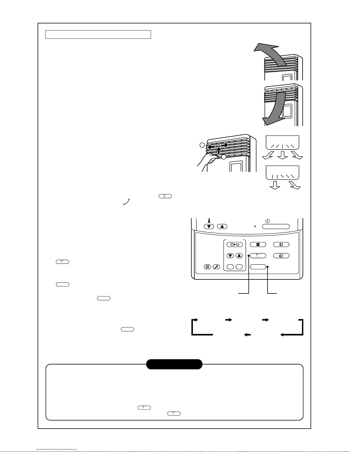
90
Tipo da posizionare sul pavimento
Regolazione della direzione dell’aria verso l’alto/verso il basso
[Nel funzionamento di raffreddamento]
Nel raffreddamento, spostare con le mani il deflettore e utilizzarlo con il punto di
uscita dell’aria in orizzontale, in modo che l’aria fredda si diffonda in tutto il locale.
[Nel funzionamento di riscaldamento
(solo per i modelli con pompa per il calore)]
Nel riscaldamento, spostare il deflettore con le mani e usare il deflettore
orizzontale impostato verso il basso, in modo che l’aria soffi verso terra.
Regolazione della direzione dell’aria verso destra/verso sinistra
[Nel caso di uso non simmetrico delle direzioni dell’aria]
Sollevare leggermente il deflettore verticale, dirigerlo verso
la direzione desiderata e poi abbassarlo.
In questo caso, non utilizzare la funzione di oscillazione.
Unità n. 1-1Nessun
display
Unità n. 1-2
Unità n. 1-4 Unità n. 1-3
ON / OFF
FAN
TEMP.
SWING/FIXTIME
MODE
VENT
UNITSET CL
FILTER
RESET
TEST
TIMER SET
1, 2 3
1
2
In questo caso, non utilizzare
la funzione di oscillazione.
INFORMAZIONI
• Se si esegue il raffreddamento con lo scarico verso il basso, sulla superficie dell’armadietto o sul deflettore
orizzontale potrebbe formarsi della condensa, con risultanti sgocciolamenti.
• Se si esegue il riscaldamento con lo scarico in orizzontale, nel locale può aumentare la irregolarità della
temperatura.
• Durante l’oscillazione, non spostare il deflettore direttamente con le mani; altrimenti si potrebbero causare
problemi. Anche se si preme il tasto
SWING/FIX
, il deflettore verticale non si arresta immediatamente. Quando si
è regolato la posizione di arresto, premere il tasto
SWING/FIX
.
[In caso di oscillazione automatica]
1
Durante il funzionamento, premere il tasto
SWING/FIX
.
• Viene visualizzato [SWING
] e la direzione
dell’aria cambia automaticamente verso l’alto/verso
il basso.
Nel caso in cui un solo telecomando controlli più
unità interne, è possibile selezionare ogni unità
interna e
impostarne la direzione dell’aria.
2
Durante il movimento di oscillazione del deflettore
dell’uscita dell’aria, premere di nuovo il tasto
SWING/FIX
.
•È possibile arrestare il deflettore dell’uscita dell’aria
nella posizione desiderata.
3
UNIT
• Per impostare singolarmente la direzione dell’aria,
premere il tasto
UNIT
per visualizzare ogni numero
di unità nel controllo di gruppo. Quindi, impostare la
direzione dell’aria per l’unità interna visualizzata.
• Se non esiste nessun display, è possibile controllare
tutte le unità interne direttamente.
• A ogni pressione del tasto
UNIT
, il display cambia
come mostrato in figura.

91
FUNZIONAMENTO CON TIMER
È possibile scegliere il funzionamento del timer fra i tre tipi seguenti.
Timer di spegnimento (OFF) : Quando l'ora del timer ha raggiunto l'ora impostata, il funzionamento si arresta.
Timer di spegnimento ripetuto : Il funzionamento si arresta ogni volta che si è raggiunta l'ora impostata.
Timer di accensione (ON) : Quando l'ora del timer ha raggiunto l'ora impostata, si avvia il funzionamento.
Operazioni con il timer
1
Premere il tasto TIMER SET.
• Il display del timer (tipo) cambia ogni volta che si preme il tasto.
• Le visualizzazioni SET DATA e orario del timer lampeggiano.
2
Premere il tasto
TIME
per selezionare “SET TIME”.
A ogni pressione del tasto
, il tempo impostato aumenta in unità di 0,5 ore (30 minuti).
Il tempo massimo che si può impostare è di 72 ore.
A ogni pressione del tasto
, il tempo impostato diminuisce in unità di 0,5 ore (30 minuti).
Il tempo minimo che si può impostare è di 0,5 ore.
3
Premere il tasto SET.
•
SETTING
scompare e appare lavisualizzazione dell’orario del timer.
(Quando la funzione di timer ON è attivata, orario del timer, timer ON
appaiono mentre tutte le altre
visualizzazioni scompaiono.)
Cancellazione delle operazioni con timer
4
Premere il tasto CL.
• Il display del timer scompare.
AVVISO
• Quando si arresta il funzionamento dopo che il timer ha raggiunto l'ora preimpostata, se si preme il tasto
ON / OFF
il timer di spegnimento ripetuto riprende il funzionamento e lo arresta dopo che l'ora del timer ha
raggiunto quella impostata.
4
3
2
1
ON / OFF
FAN
TEMP.
SWING/FIXTIME
MODE
VENT
UNITSET CL
FILTER
RESET
TEST
TIMER SET
OFF
(Timer di spegnimento) (timer di spegnimento ripetuto)
Nessun display
(Timer di accensione)
OFF ON

92
INSTALLAZIONE
Posizione di installazione
ATTENZIONE
• Per l’installazione, selezionare un luogo che sia in grado si sostenere in sicurezza il peso
dell’unità.
Se il luogo di installazione non è abbastanza solido da sostenere l’unità ed essa cade, si possono provocare
ferite.
AVVERTENZA
• Non installare l’unità in un luogo nel quale si possono verificare perdite di gas.
Il gas accumulatosi nelle vicinanze dell’unità potrebbe essere incendiato dall’unità stessa.
REQUISITI
• Un luogo che consenta di installare l’unità in piano
• Un luogo che fornisce abbastanza spazio per eseguire in sicurezza la manutenzione dell’unità
• Un luogo nel quale lo scarico di acqua dall’unità non presenti nessun problema.
Evitare i seguenti tipi di luoghi:
• Luoghi in cui è presente sale in grosse quantità (zone nei pressi del mare) o dove sono presenti gas
solforosi in grosse quantità (aree nel pressi di sorgenti termali).
[Se si deve usare l’unità in tali zone, è necessaria una manutenzione speciale.]
• Luoghi in cui vengono generati oli (compresi oli per macchine), vapore, fumo d’olio o gas corrosivi
• Luoghi in cui si usano solventi organici
• Luoghi nelle vicinanze di apparecchi che generano segnali ad alta frequenza
• Luoghi nei quali l’unità esterna diriga il soffio dell’aria verso la finestra di un vicino
• Luoghi nei quali il rumore dell’unità esterna potrebbe costituire un problema
• Luoghi con scarsa circolazione di aria
Collegamenti elettrici
ATTENZIONE
Controllare se la messa a terra è stata eseguita correttamente.
La messa a terra è necessaria. Se la messa a terra è incompleta, si possono provocare folgorazioni.
AVVERTENZA
Controllare che sia montato l’interruttore per dispersioni a terra.
È necessario montare un interruttore per dispersioni a terra. Altrimenti, si possono provocare folgorazioni.
Verificare che siano stati utilizzati fusibili della capacità corretta.
L’uso di fili o di filo di rame può provocare incendi o problemi.
Per l’alimentazione, utilizzare un circuito con tensione nominale esclusiva per il condizionatore d’aria.
Per scollegare l’apparecchio dall’alimentazione principale di rete.
Questo apparecchio deve essere collegato alla rete elettrica per mezzo di un interruttore di circuito o di un
interruttore con una separazione dei contatti di almeno 3 mm.

93
MANUTENZIONE
Pulizia del filtro dell’aria
• Se sul telecomando viene visualizzata l’indicazione [FILTER], è necessario eseguire la manutenzione del filtro
dell’aria.
• Se il filtro dell’aria è otturato, diminuisce l’effetto di raffreddamento/riscaldamento.
ATTENZIONE
Prima di eseguire la manutenzione, spegnere l’interruttore principale dell’alimentazione.
• Non eseguire personalmente la manutenzione giornaliera e/o la pulizia del filtro dell’aria.
La pulizia del filtro dell’aria e delle altre parti dell’unità interna è un lavoro pericoloso da fare in posti alti e
pertanto si raccomanda di farlo fare a persone del servizio di assistenza tecnica. Non cercare di farlo da
soli.
<Manutenzione giornaliera>
• Per la manutenzione giornaliera, compresa la pulizia del filtro dell’aria, interpellare un tecnico qualificato
dell’assistenza, soprattutto per i modelli seguenti:
Tipo a cassetta con scarico d’aria a 4 vie Tipo standard a condotto nascosto Tipo da installare al soffitto
Tipo a cassetta con scarico d’aria a 2 vie Tipo a Condotto Sottile
Tipo a cassetta con scarico d’aria a 1 via Condotto nascosto del tipo ad alta pressione statica
ON / OFF
FAN
TEMP.
SWING/FIXTIME
MODE
VENT
UNITSET CL
FILTER
RESET
TEST
TIMER SET
CODE No.
UNIT No.
TEST
SETTING
DATA
SET
R.C. No.
H
Indicazione FILTER
Avvisa del momento in cui è necessario pulire
il filtro dell’aria.
Azzeramento indicazione FILTER
Dopo la pulizia, premere l’interruttore FILTER.
L’indicazione “FILTER” scompare.
Tipo a cassetta con
scarico d’aria a 4 vie
Tipo da
installare al soffitto
Tipo a cassetta con
scarico d’aria a 2 vie
Tipo standard
a condotto nascosto
Tipo a cassetta con
scarico d’aria a 1 vie
Condotto nascosto del tipo
ad alta pressione statica
NON ADATTO
NON ADATTO
Tipo a
Condotto Sottile
NON ADATTO
NON ADATTO
NON ADATTO
NON ADATTO
NON ADATTO

94
Tipo per mura alte
(Modello: Serie 1H)
• Premere la sporgenza al centro del filtro dell’aria. Viene estratto il fermaglio.
• Togliere il fermaglio del filtro dell’aria, tirare il filtro dell’aria verso il basso
mentre lo si preme verso il lato dell’unità principale.
(Modello: Serie 2H)
• Aprire la griglia di ingresso dell'aria.
Sollevare la griglia di ingresso dell'aria in posizione orizzontale.
• Afferrare le maniglie sinistra e destra del filtro dell’aria e sollevarlo
leggermente e poi tirarlo verso il basso per estrarlo dal relativo supporto.
Premere il filtro
dell’aria e tirarlo
verso il basso.
Pannello anteriore
(Lato inferiore)
Manopola del
filtro dell’aria
Supporto del filtro dell'aria
Tipo ad armadietto da posizionare sul pavimento
• Spingere leggermente verso il basso la parte superiore della porta di
aspirazione e poi tirarla verso di sé per rimuoverla.
• Estrarre il filtro dell’aria che si trova all’interno della porta di aspirazione.
Tipo nascosto da posizionare sul pavimento
• Spingere verso il basso il gancio del filtro dell’aria situato sul pannello
anteriore (lato inferiore).
• Tirare il filtro dell’aria verso di sé per rimuoverlo.
Tipo da posizionare sul pavimento
Rimozione/montaggio del filtro dell’aria
• Tirare il filtro dell’aria verso di sé.
• Per montare il filtro dell’aria, inserirlo nel corpo principale e spingerlo in
esso.
NOTA
• Per la pulizia del filtro dell’aria, utilizzare un prodotto per pulizia o una spazzola pulita.
Se le macchie sono ampie, lavare il filtro dell’aria in acqua tiepida miscelata con
detergente neutro.
• Dopo il lavaggio, sciacquarlo per bene e poi lasciarlo asciugare all’ombra.
• Dopo la pulizia, reinstallare il filtro dell’aria.

95
Reinstallare il filtro dell’aria.
• Inserire la parte superiore del filtro dell'aria allineando i bordi destro e sinistro sull'unità interna fino a quando è
fissato bene.
• Chiudere la griglia di ingresso dell'aria.
Se la spia FILTER del filtro sull'unità interna è visualizzata, per spegnerla premere il tasto FILTER sul
telecomando o il tasto TEMPORARY sull'unità interna.
Supporto del filtro dell'aria
Non utilizzare.
Polvere per
la pulizia
Benzene
Solvente
Abito per
lavoro con
prodotti
chimici
Pulizia della griglia di ingresso dell'aria
1. Rimuovere la griglia di ingresso dell'aria.
Tenere entrambi i lati della griglia di ingresso dell'aria e
aprirla verso l'alto.
Spostare il braccio centrale a sinistra e rimuovere la griglia.
2. Lavarla con acqua usando una spugna morbida o un
asciugamano.
(Non utilizzare nessuna spazzola metallica dura e nessun
altro tipo di spazzola dura).
• L'uso di oggetti duri può graffiare la superficie della griglia
di ingresso dell'aria e strappare il rivestimento del metallo.
• Se è molto sporca, pulire la griglia di ingresso dell'aria con
un detergente per cucina e sciacquarla con acqua.
3. Strofinare e lasciar asciugare l'acqua dalla griglia di ingresso
dell'aria.
4. Inserire i bracci sinistro e destro della griglia di ingresso
dell'aria negli alberini che si trovano sui due lati del
condizionatore d'aria, spingerli dentro completamente e poi
spingere il braccio centrale.
5. Controllare che il braccio centrale sia stato inserito
completamente e chiudere la griglia di ingresso dell'aria.
• Per controllare che la griglia sia chiusa completamente,
premere i punti indicati dalle frecce (quattro) situati in fondo
alla griglia di ingresso dell'aria.
Pulizia dell’unità interna/del telecomando
AVVERTENZA
• Pulire con un panno morbido e asciutto.
• Se è molto sporca, l'unità interna può essere pulita con un
panno bagnato con acqua fredda.
• Non usare mai un panno bagnato per pulire il
telecomando.
• Non usare mai per la pulizia uno straccio per la polvere
trattato chimicamente e non lasciare mai materiali simili
per lungo tempo sull'unità. Potrebbe danneggiare o
scolorire la superficie dell'unità.
• Per la pulizia, non usare benzene, diluente, polvere per
lucidatura o solventi simili. Queste sostanze possono
causare la rottura o la deformazione della superficie di
plastica.

96
Se si pensa di non utilizzare l’unità per più di 1 mese
Pulire con un panno
morbido e asciutto!
Quando non si è
utilizzato per lungo tempo,
usarlo dopo averlo fatto
asciugare!
1. Azionare la ventola per 3 o 4 ore per asciugare l’interno dell’unità.
• Impostare la modalità “FAN”.
2. Arrestare il condizionatore d'aria e spegnere l'interruttore
principale di alimentazione oppure l'interruttore del circuito.
Controlli prima dell'uso
1. Controllare che siano installati i filtri dell'aria.
2. Controllare che l'uscita o l'ingresso dell'aria non siano bloccati.
3. Per accendere il condizionatore d’aria, accendere l’interruttore
principale di alimentazione o l’interruttore del circuito della presa
di rete.
NOTA
Per i sistemi di condizionamento d'aria usati regolarmente, si
raccomanda caldamente di eseguire pulizia e manutenzione delle
unità interna/esterna.
Come guida generale, se si usa un'unità interna per circa 8 ore
ogni giorno, è necessario pulire le unità interna/esterna almeno
una volta ogni 3 MESI. La pulizia e la manutenzione devono
essere eseguite da personale qualificato.
La mancata pulizia regolare delle unità interna/esterna avrà come
risultato uno scarso effetto di raffreddamento, formazione di
ghiaccio, perdite d'acqua e anche guasti prematuri del
compressore.
SUGGERIMENTI PER UN FUNZIONAMENTO ECONOMICO
Mantenere la temperatura della stanza a un livello confortevole.
Pulire i filtri dell'aria.
Se il filtro dell'aria è bloccato, il flusso dell'aria e le prestazioni del condizionatore si riducono.
Non aprire mai le porte e le finestre più del necessario.
Per mantenere aria fredda o calda nel locale, non aprire mai le porte e le finestre più del necessario.
Tende alle finestre
Durante il raffreddamento, chiudere le tende per evitare la luce solare diretta.
Durante il riscaldamento, chiudere le tende per mantenere il calore nella stanza.
Impostare un flusso d'aria uniforme nella stanza.
Regolare la direzione del flusso d'aria, in modo da
ottenere una circolazione d'aria uniforme.
Controllo
Molto freddo
Pulire.
Chiudere.
Dirigere il soffio verso l'alto.
Dirigere il flusso verso il basso.
Regolazione del
flusso dell'aria
Aria fredda
e secca
Aria
calda
97
OPERAZIONI E PRESTAZIONI DEL CONDIZIONATORE D’ARIA
Controlli prima dell’uso
• Controllare che il filo di messa a terra non sia scollegato o fuori posto.
• Controllare che il filtro dell’aria sia installato nell’unità interna.
Capacità di riscaldamento (solo per i modelli con pompa per il calore)
• Per il riscaldamento, viene adottato un sistema con pompa per il calore
che aspira l’aria calda dall’esterno e la scarica nel locale.
Se la temperatura dell’aria esterna scende, la capacità di riscaldamento diminuisce.
• Se la temperatura dell’aria esterna è bassa, si raccomanda di usare anche un’altro apparecchio di
riscaldamento.
Sbrinamento durante il riscaldamento (solo per i modelli con pompa per il calore)
• Se durante il funzionamento di riscaldamento sull’unità esterna si è formato un po’ di ghiaccio, la modalità di
funzionamento cambia automaticamente nella modalità di sbrinamento, per aumentare l’effetto di riscaldamento
(per circa da 2 a 10 minuti).
• Durante lo sbrinamento, le ventole delle unità inter na ed esterna si arrestano.
Protezione per 3 minuti
• Quando il condizionatore d’aria è stato riavviato immediatamente dopo un arresto o dopo l’accensione
dell’interruttore di alimentazione, l’unità esterna non funziona per circa 3 minuti. Ciò serve a proteggere il sistema.
Interruzione di corrente
• Se durante il funzionamento si verifica un’interruzione di corrente, il funzionamento si arresta.
• Quando si riavvia il funzionamento, premere di nuovo il tasto ON/OFF.
Rotazione della ventola con l’unità in stato di arresto.
• Mentre le altre unità interne sono in funzione, la ventola delle unità interne in “standby” ruota, per proteggere le
macchine, per diversi minuti ogni ora.
Dispositivo di protezione (Interruttore di alta pressione)
L’interruttore dell’alta pressione arresta automaticamente il condizionatore d’aria quando viene applicato ad esso
un carico eccessivo.
Nel caso di azionamento del dispositivo di protezione, la spia di funzionamento rimane accesa, ma il
funzionamento si arresta.
Quando il dispositivo di protezione è attivato, i caratteri di controllo “
” sul display del telecomando lampeggiano.
Il dispositivo di protezione può essere attivato nei casi seguenti.
Nel funzionamento di raffreddamento
• Quando la porta di aspirazione o quella di scarico dell’unità esterna sono chiuse.
• Quando contro la porta di scarico dell’unità esterna soffia continuamente un forte getto d’aria.
Nel funzionamento di riscaldamento (solo per i modelli con pompa per il calore)
• Quando la polvere o lo sporco aderiscono eccessivamente al filtro dell’aria dell’unità interna.
• Quando la porta di scarico dell’unità interna è bloccata.
Raffreddamento/riscaldamento del condizionatore d’aria a MiNi-SMMS
Nei condizionatori d’aria a MiNi-SMMS, è possibile controllare singolarmente ogni unità interna.
Tuttavia, nelle unità interne collegate alla stessa unità esterna non è possibile eseguire contemporaneamente
raffreddamento e riscaldamento.
Se si eseguono contemporaneamente raffreddamento e riscaldamento, l’unità interna che esegue il
raffreddamento si arresta e si accende il display “
”.
L’unità inter na che esegue il riscaldamento continua a funzionare.
Se il gestore dell’impianto ha eseguito le impostazioni COOL o HEAT, non è possibile eseguire altri tipi di
funzionamento diversi dall’impostazione uno.
Se si eseguono altri tipi di funzionamento diversi dall’impostazione uno, si accende il display “
” e il
funzionamento si arresta.
Caratteristiche del funzionamento di riscaldamento (solo per i modelli con pompa per il calore)
• Subito dopo l’inizio del funzionamento non viene emessa aria calda. Dopo da 3 a 5 minuti (a seconda del locale
o della temperatura esterna) e dopo che lo scambiatore interno di calore si è riscaldato, inizia ad essere emessa
aria calda.
• Durante il funzionamento, se la temperatura esterna diventa alta, l’unità esterna potrebbe arrestarsi.
• Se altre unità esterne eseguono il riscaldamento mentre la ventola è in funzione, è possibile arrestare
temporaneamente il funzionamento della ventola per impedire l’emissione di aria calda.
ATTENZIONE
Accendere l’interruttore di
alimentazione 12 o più ore
prima di avviare il
funzionamento dell’unità.
 Loading...