

SERVICE
Forçage des PMV dans le groupe.
Shunter TP1
Mettre le rotatif sw1 sur 0 et TP1 shunté ouverture de la PMV1 pendant 2 mn
Mettre le rotatif sw1 sur 1 et TP1 shunté ouverture de la PMV2 pendant 2 mn (page 42 du MARF102
Couper l'alimentation électrique pour que les vannes restent en ouverture.
Forçage des PMV sur les multi-controllers
Basculer le bouton rotatif de couleur (situé à droite) sur la position 0 et shunté TP1 pour forcer l'ouverture de la PMVA.
Basculer le bouton rotatif de couleur (situé à droite) sur la position 1 et shunté TP1 pour forcer l'ouverture de la PMVB.
Basculer le bouton rotatif de couleur (situé à droite) sur la position 2 et shunté TP1 pour forcer l'ouverture de la PMVC.
Basculer le bouton rotatif de couleur (situé à droite) sur la position 3 et shunté TP1 pour forcer l'ouverture de la PMVD.
Couper l'alimentation électrique pour que les vannes restent en ouverture.
DATA
TOSHIBA
SUPER
CCOOUHEAT
Outdoor Units
Multi-Controller
MULTI
AIR
CONDITIONER
FLEX SERIESI
FILE
NO.
300
-
950
RBM-Y
Forcaae des
Shunter TPI
Mettre le rotatif swl sur O et TPI shunté ouverture de la PMVI pendant 2 mn
Mettre le rotatif swl sur 1 et
Couper I'alimentation électrique pour que les vannes restent en ouverture.
Forcaae des
Basculer le bouton rotatif de couleur (situé à droite) sur la position O et shunté TPI pour forcer I'ouverture de la PMVA.
Basculer le bouton rotatif de couleur (situé à droite) sur la position 1 et shunté TPI pour forcer I'ouverture de la PMVB.
Basculer le bouton rotatif de couleur (situé à droite) sur la position 2 et shunté TPI pour forcer I'ouverture de la PMVC.
Basculer le bouton rotatif de couleur (situé à droite) sur la position 3 et shunté TPI pour forcer I'ouverture de la PMVD.
Couper
PMV
dans le aroupe.
TPI shunté ouverture de la PMV2 pendant 2 mn (page 42 du MARF102
PMV
sur les multi-controllers
I'alimentation électrique pour que les vannes restent en ouverture.
1031FE
PRINTED
IN
JAPAN,
July,
1993
@

TABLE
1
.
MULTI AIR CONDITIONER SYSTEMS AND
THEIR BASIC COMPONENTS
1.1
.
Indoor Remote Controllera
.
1.2 Outdoor Unlis 3 16.3 . Test Run Check
1.3 . Multi-wnlmllera
14
Indoor Units
2
.
CONTRO1 SYSTEM
3
.
REFRIGERANT CYCLE DIAGRAM
4
.
COMBINATION OF INDOOR UNITS AND
OUTDOOR UNITS
4.1 . Baslc Criterls for Combinatlons
4-2
Procedure for Checking ihe Comblnation 7 20.2 . How lo Read the Malfunction Check
4-3 . Exemplee of Connectlon Check
5
.
SPECIFICATIONS OF OUTDOOR UNIT
5.1 . Explanatlon of
Electrlc Characterlstlcs Calculation
6
.
EXTERNAL VIEW
6.1 Outdoor Unit 11
6.2 . Multlcontroller
.
6.3
Header
7
.
WIRING DIAGRAM
7.1. outdoor unlt (YAR.F~~H~~, MAR-F~O~HTM~) 14
7.2 . Mulll-wntmller (RBY.Y1031FE, Yl041FE)
.
8
ELECTRICAL SPECIFICATIONS
l
.
Speclflcatlons
8.2
.
Speclflcatlons oi Inverter Asssmbly Parts
8.3. Speciflcatlons of Multl-contraller Parts
.
9
Coollng/Heatlng Capaclty Characteristics
.
9.1
Range of Operalion 21
9.2 . Coollng Capaclty Calculation
9.3 . Heatlng Capaclty CaIculatIon
10
.
AIR TIGHTNESS TEST, AIR PURGING WITH
VACUUM PUMP AND CHARGING OF
ADDlTlONAL REFRIGERANT
10.1 . Air Tlghtness Test
10.2 . Alr Purging with a Vacuum Pump
10.3 . Addltlonal Refrlgerant Charglng and
Amount of Addltlon
11
.
PIPING LENGTH AND CHARGED
REFRIGERANT AMOUNT
11.1
.
Maln
Branch (One Mulii-Controller)
11.2 . Sub Branch (Two Multl-Controllers)
12
.
DESCRIPTION OF OPERATION
t
2.1 . Slmultaneous Coollngl
Heatlng Operatlon Control Outline
12.2 . Functlons
13
OPERATIONS OF EACH SENSOR
.
13.1. Multi-Controller 33
.
13.2 Outdoor Unlt
14
.
COOLINGIHEATING AUTOMATIC REMOTE
CONTROLLER
14-1
.
CoolinglHeatlng Automatic
ChangeOver Operatlon
15
.
IMPORTANT MATTERS T0 BE CHECKED
BEFORE TEST RUN AND SERVICING
15-1
.
Reglstered Indoor Unlt Code Numbers
15-2 . Connections o1 Refrigerant Piping and
Control Wires
Multi-Controller 37
15-3 . Conneclions of Control Wires between Units
..............................................................
.......................
................................................................ .
...........................................
...............................................
.............................................
.............................................................. .
..........................................................
........,..,
"-m.,.".-
...........................................
of
Refrlgerant Cycle Parto
...................................................
.............................
................................................
and
Operations of Solenoid Valves
.........................................................
.....................................................
..-...
-
..................................................
beiween Indoor Units and
......................................................
...........................
...,.......................
..
.............................
.............
..................
................................
................................
...-.".....
..................................
..................................
................
............
.......................
............................
............
....................
...............
.............
..................
..........................
..
...............
...........................
................................
........................
.......................
......................
.........................
.................
...........................................
...........
...................
....
...
.......
........
OF
2
3
3
3
3
5 19
6
6
8
9
10
11
12
13
14
16
18
18
19
20
21
22
23
A
25
25
26
27
28
28
29
30
30
31
33
34
35
35
36
36
37
CONTENTS
16
.
TEST RUN
.
16.1 Test Run Prooedure 38
16.2
.
Check
.
Guidelines
16.4
17
.
SERVICING PROCEDURES
18
.
CHECK CODE DISPLAY SYSTEM CHART
.
IDENTIFICATION PROCEDURES
20
.
JUDGMENT OF MALFUNCTIONS WITH THE
REMOTE CONTROLLER INDICATION
20.1 . Malfunction Check Dlsplay Operatlon
Monltor Display
20.3 . The Check Code and Ihe Judgmenl
20.4
.
Malfunctlon Judgmeni wlth the Self-Dlagnostlc
Function of the
20.5 . Malfunction Judgment wlth the Sell-Dlognoatlc
Functlon of the Multl-Controller
20.6. PMV Openlng
Pressure Sensor Data Code Display
Conversion Table
21
.OTHERS
21.1 . Microprocessor System Dlagram and the Tlme
Requlred lo Judge the Malfunctlon
21.2 . A Check of ihe Conlrol Clrcuit Power Voltage of
the
Multi-Controller Control Board
21.3
.
A
Check of rhe Control Clrcult Power Voltage of
theoutdoot Interface Board
21.4 220 - 240V Systein Dlagram
.
22 . REMOTE CONTROLLER DISCRIMINATION
FUNCTION, OUTDOOR UNIT
D
ISCRIMINATION FUNCTION
.
22.1 Search from the Remote Controller
.
22.2 Search from Outdoor Unit 76
23
.
CHECK FOR REFRIGERANT PIPING AND
INTER-UNIT WIRING CONNECTION
23.1
.
Check System Procedure8
24
.
REMOVAL METHOD
24.1 Outdoor Unlt (MAR.FSlHTM0, FlOlHTM8)
.
24.2. Multi-Controller (RBM.Y1031FE, Y1 WlFE)
25
.
EXPLODED VIEWS AND PARTS LIST
25.1 . Outdoor Units
(MAR-FS1 HTM8, MAR-FlOIHTM8)
25.2 . Electrical Parto Assembly
(MAR-FS1
25.3
.
Multi-Controller
(RBM.Y103IFE, RBM-Yl041FE)
25.4 . Eleclrical Parts Assembly
(RBM.Y1031FE, RBM-Y1041FE)
.........................................................
...................................................
before
Test Run
..............................................
...........................................-.............
..................................................................
............................
...................
...........
.....................
.,.,.,
......,.....,..
"v-.
.........................
Outdoor Unlt
....................................
.....................
Degree,
Temperature Sensor and
.......................................................
............................................................
........................
...........................
..........................
.............................
.........................
........................
...............
J
..............
..............
...........
...........................
..........................
................................
................................
HTMB,
MAR-F101HTM8)
.........................................
...........................
........................................
30
38
39
41
43
....
45
46
49
49
50
51
57
.....
64
67
71
71
72
......
73
....
74
76
36
77
70
78
83
86
...8
6
.88
90
91
1.
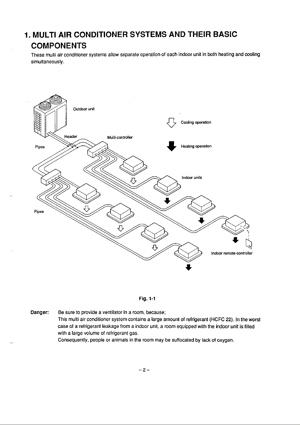
MULTI AIR CONDITIONER
COMPONENTS
These multi
sirnultaneously.
air
conditioner systerns allow separale operation of each indoor unit
Multi-controller
SYSTEMS
AND THEIR BASIC
in
both heating and cooling
Cooling operaiion
0
Heating operation
+
Danger:
Fig.
1-1
Be
sure to provide a ventilator in a room, because;
This multi air conditioner system contains a large amount
a
case of a refrigerant leakage frorn
with a large volume of refrigerant gas.
Consequently, people or
anirnals in the room
indoor unit, a room equipped with the indoor unil
may
be
suffocated by lack of oxygen.
of
refrigerant
Indoor remote controller
(HCFC
22).
In
the worst
is
filled

1-1.
Indoor remote controllers come either with or without lhe automatic heatinglcooling mode lunction. Automatic
heating
1-2.
Two types of outdoor units are available in the iine-up:
both types are used in combination.
1-3.
Multi-controllers are refrigerant distributing devices to connecl multiple indoor units with the outdoor unit. The
series includes 3-way (for 3 indoor units)and 4-way multi-controllers. To make
indoor units) system, the 3-way and 4-way mu#icontrollers are used in combination wilh a header.
1-4.
There is a wide range ol indoor units totaling
Refer to
Indoor
and
Remote
cooling operations can be controlled by those that equipped with Ihe funclion.
Controllers
Outdoor Units
8
HP
and
10
HP.
For
16
Multi-controllers
Indoor
table
4-1.
Units
13
models
(3
types with 6 capacity ratings from
HP or larger applications,
a
5-,
6-,
7-
or 8-way (for
1.5
to 5 HP).
8
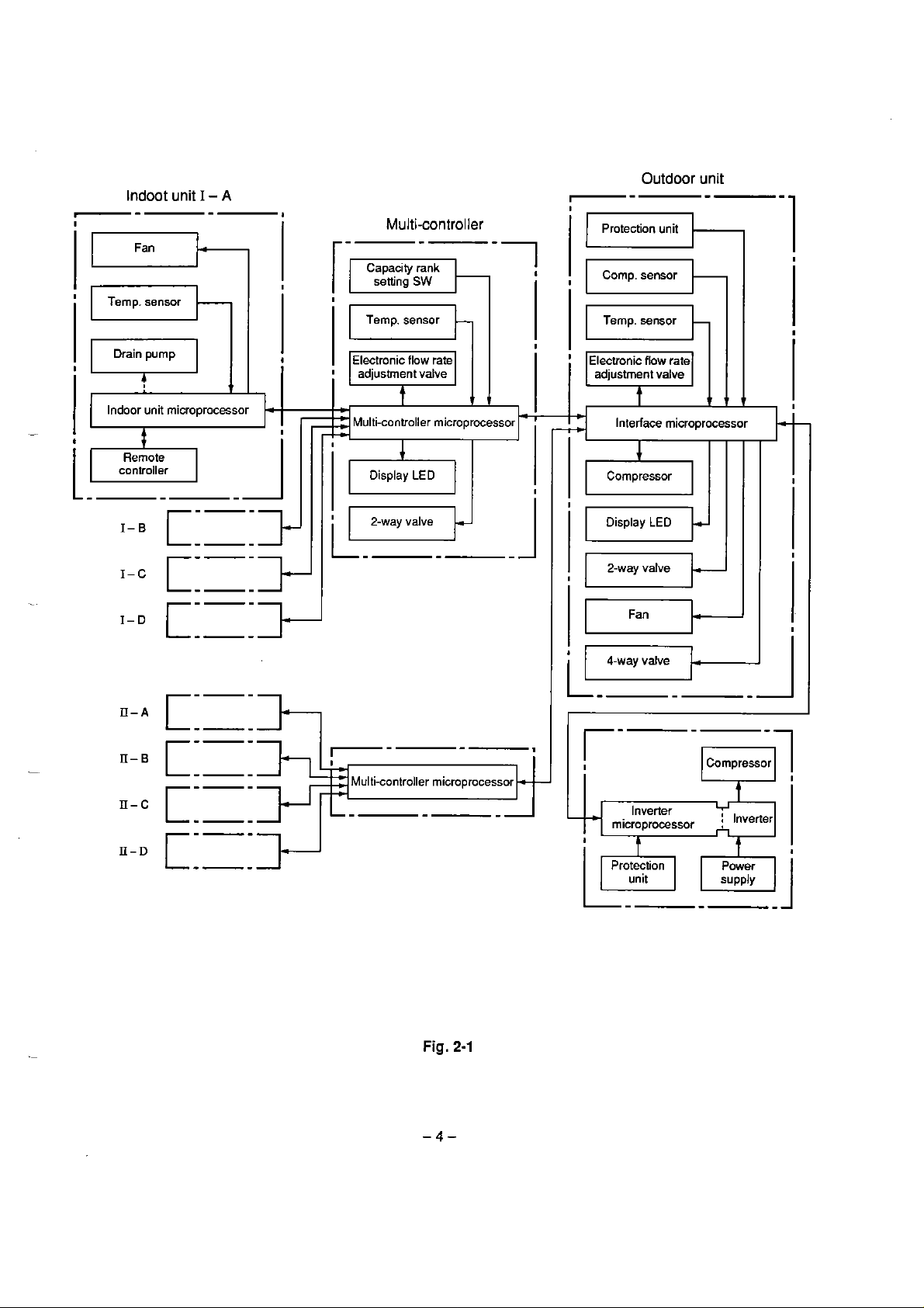
2.CONTROL
The refrigerant and electrical systems of the multi air conditioner system are controlled by the
multi-controllers and rnicroprocessor contained inside the outdoor unit. The indoor units of the CooltHeat
Flex Series of Multi Air Conditioner Systerns are the same units as in the RAV-series air wnditioner systems.
For system operation, first the microprocessor in each indoor unit reads the difference between Ihe current
room temperature and desired temperature which has been set by the remote
corresponding
operation comrnands
On the basis of the operation commands sent lrom al1 the indoor microprocessors, the multi-controller
microprocessors adjust the cooling and heating operation commands and send them to the interface
microprocessor in the ouldoor unit. The inleriace microprocessor calculates the capacity required for cooling
and heating, determines Ihe operation mode in the outdoor unit and
compressor and
frequencies of
SYSTEM
controller, determines the
demand signai, and transmits this to the multicontroller rnicroprocessors in the form
(ONJOFF,
al1 the requested heating command dilference between al1 the requested cooling command
the compressor of al1 the indoor units.
coolinglheating operation mode, operation frequency of the compressor).
calculates frequencies of the
of
-
r-
Indoot unit
Fan
Temp. sensor
Outdoor
I
-
A
1
Multi-controller
Capacity rank
setting
SW
Temp. sensor
-
7-
Protection unit
Comp. sensor
Temp. sensor
unit
.
-
-
-
1
Electronic flow rate
adjustment valve adjustment valve
Indoor unit microprocessor
.>
I-.
cm-'>
-P-
Multi-controller microprocessor Interiace microprocessor
Display
LED
2-way valve Display
Electronic flow rate
Compressor
LED
2-way valve
Fan
v
4
"'"
:
L.
----
----
I-
Multi-controller microprocessor
r-
-
Inverter
microprocessor i Inverier
Compressor
V
-1
D
t-----
----
Fig.
2-1
Ptotection
L+
unit

3.
REFRIGERANT
CYCLE
DIAGRAM
Fig.
3-1
Exarnples
of
8
and
10
HP
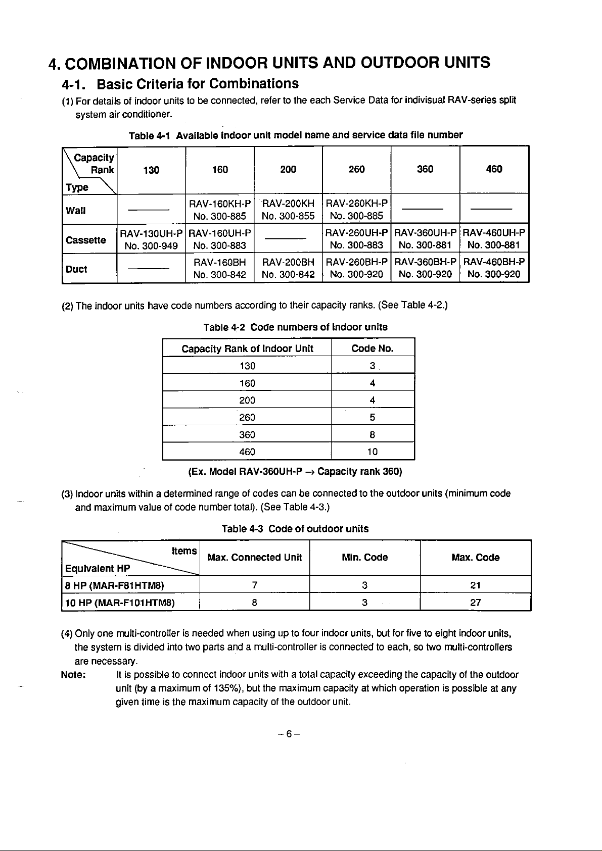
4.
COMBINATION OF INDOOR UNITS AND
OUTDOOR
UNITS
4-1.
(1) For details of indoor units to be connected, referto the each Service Data for indivisual RAV-series split
Wall
Cassette
Duct
(2)
Basic
systern air conditioner.
The indoor units have code numbers according to their capacity ranks.
Criteria for Combinations
Table
4-1
Available indoor unit mode1 name and service data file nurnber
130
RAV-130UH-P
No. 300-949
Capacity Rank of tndoor Unit
160
RAV-16OKH-P
NO. 300-885
RAV-1 6OUH-P
No.
300-883
RAV-160BH
NO.
300-842
Table
4-2
130
160
200
260
360
460
-RAV-200KH
NO. 300-855
RAV-200BH
NO. 300-842
Code numbers of indoor units
200
260
RAV-260KH-P
NO. 300-885
RAV-260UH-P
No. 300-883
RAV-260BH-P
NO.
300-920
Code No.
3.
4
4
5
8
10
360
RAV960UH-P
No. 300-881
RAV-36OBH-P
NO. 300-920
(See
Table
4-2.)
460
RAV46OUH-P
No.
300-881
RAV-460BH-P
NO. 300-920
(Ex.
Model RAVS6OUH-P + Capacity rank 360)
(3)
Indoor units within a determined range of codes can be connected to the outdoor units (minimum code
and maxirnum value of code number total). (See Table
4-3
Code of outdoor units
7
with
but the maximum capacity at which operation is possible at any
8
HP
(MAR-F81
l0
HP
(MAR-F1 O1 HTM8) 8
(4)
Only one multi-controller
the systern is divided into two
are necessary.
Note:
HTMB)
It is possible to connect indoor units
unit (by a maxirnurn
given time is the maximum capacity of the outdoor unit.
Table
Max.
Connected Unit Min. Code
is
needed when using up lo four indoor units, but for five to eight indoor units,
parts and a multi-controller is connected lo each, so two multi-controllers
of
13S0h),
4-3.)
Max.
3
3
a total capacity exceeding the capacity of the outdoor
2
27
Code
1
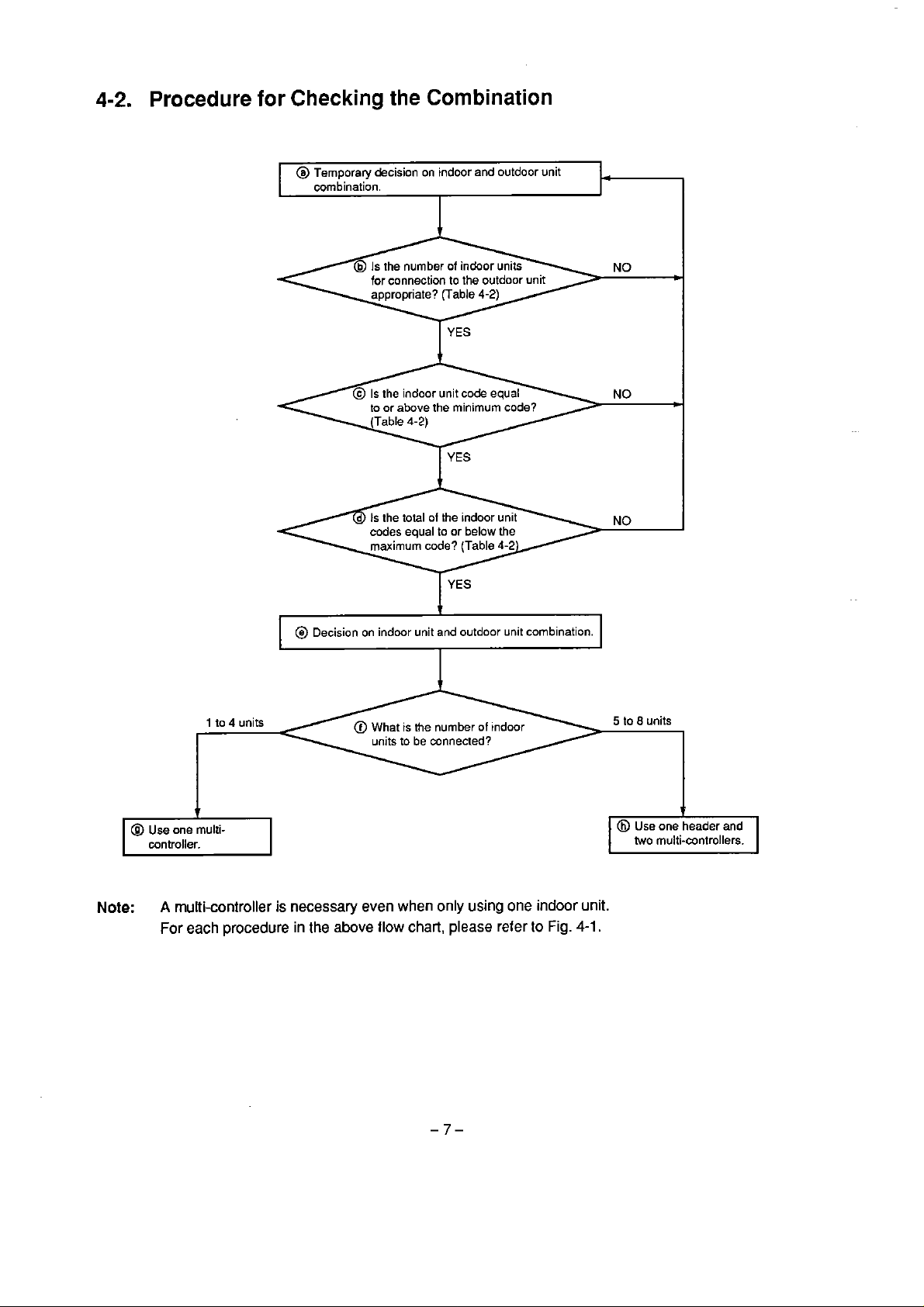
4-2.
Procedure
for
Checking
combination.
the
Combination
Note:
1
to
4
A
multi-controller
For
each
procedure
@
L
units
is
necessary
in
Decision on indmr unit and outdoor unit combination.
@
What
is
the
nurnber
of
indoor
the
even when
above
flow
only
chart,
using
please
one indoor
reter to
Fig.
unit.
4-1.
5
io
8
units
two
multi-wntrollers.

4-3.
Examples
of
Connection
Check
code
@Check
for
the
unii
qliantiy
Fig.
4-1
6-o)
.
Totai Indoor
<130>~9+3~3
0TYType33a3
Cr)
(130I~~pe-3ra
(200)
(200')
(200)
Totai Indoor
unitcode
Outdoor
unitcode
Outdoor
~ype
-
:
L,,,,,,J
unit
Max.
Type
-c
Type
-
~~~e + 423
~ype
-,
,,,,,,
unit
Max.
8z3
code
3 r 3
4
r
3
423
code
7
,
'
@~heck
for
M,,co*
h
,
'I
i
C
lhe
-
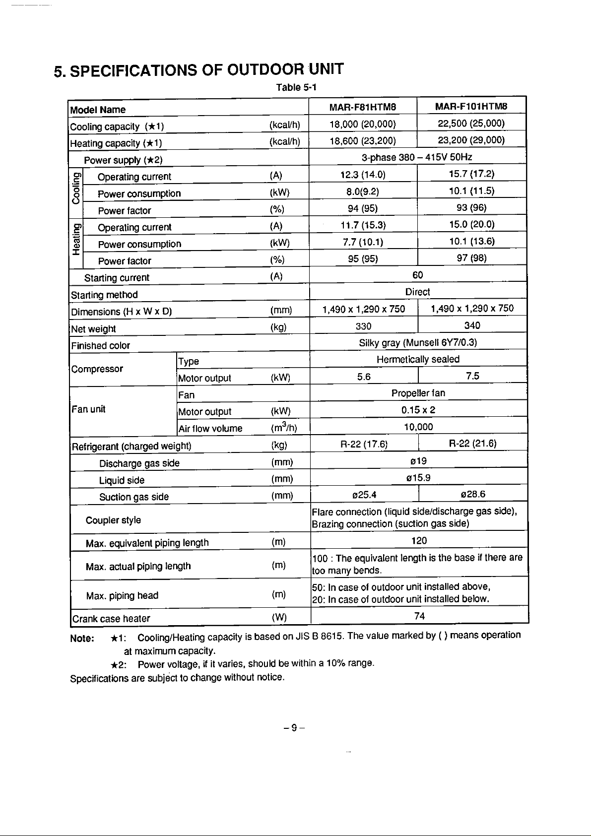
5.
SPECIFICATIONS
OF OUTDOOR
Table 5-1
UNIT
Model
Name
Cooling capacity (h 1) (kcallh)
Heating capacity (*l
Power supply
Operating current
.-
-
O
Power consumption (kW)
8
Power factor
Operating currenl
.-
C
m
CB
Power oonsumption (kW)
I.
Power facior ("/o)
Starìing current
Starting rnethod
Dimensions
Net
weight
Finished color
Compressor
Fan unii
(H
(*2)
x W x
)
D)
TYP~
Motor output
Fan
Motor output
Air flow volume (m3/h)
(kcallh)
(A)
(%l
(A)
(A)
(mm)
(kg)
(k
W)
(kW)
MAR-F81
18,000 (20,000)
18,600 (23,200)
12.3 (1
1 1.7 (15.3)
1,490 x 1,290
HTM8
3-phase 380 - 415V 50Hz
4.0)
8.0(9.2)
94
(95)
7.7 (10.1)
95
(95)
330
Silky gray (Munsell
5.6
MAR-FIO1
22,500 (25,000)
23,200 (29,000)
15.7 (17.2)
10.1 (11.5)
15.0 (20.0)
10.1 (13.6)
60
Direct
x
750
Herrnetically sealed
Propeller fan
0.15
1,490 x 1,290 x 750
6Y710.3)
x
2
10,000
93
97
HTMB
(96)
(98)
340
7.5
Refrigerant (charged weight)
Discharge gas side (mm)
Liquid side (mm)
Suction gas side (mm)
Coupler style
Max.
equivalenl piping length
Max. actual piping
Max. piping head
Crank case heater
Note:
Specificalions are subject to change without notice.
l:
al maxirnum capacity.
*2:
length
CoolingtHeating capacity
Power voltage,
ii
it varies, should be within a 10% range.
is
based on
(kg)
(m)
(m)
(m)
(W)
R-22
(17.6) R-22 (21.6)
019
015.9
025.4
Flare connection (liquid sideldischarge gas side),
Brazing connection
100
:
The equivalent length is the base
many bends.
too
50: In case of outdoor unit installed above,
20: In case of outdoor unit installed below.
JIS B 8615. The value marked by
1
(suction gas side)
120
74
028.6
(
)
means operation
if
there are
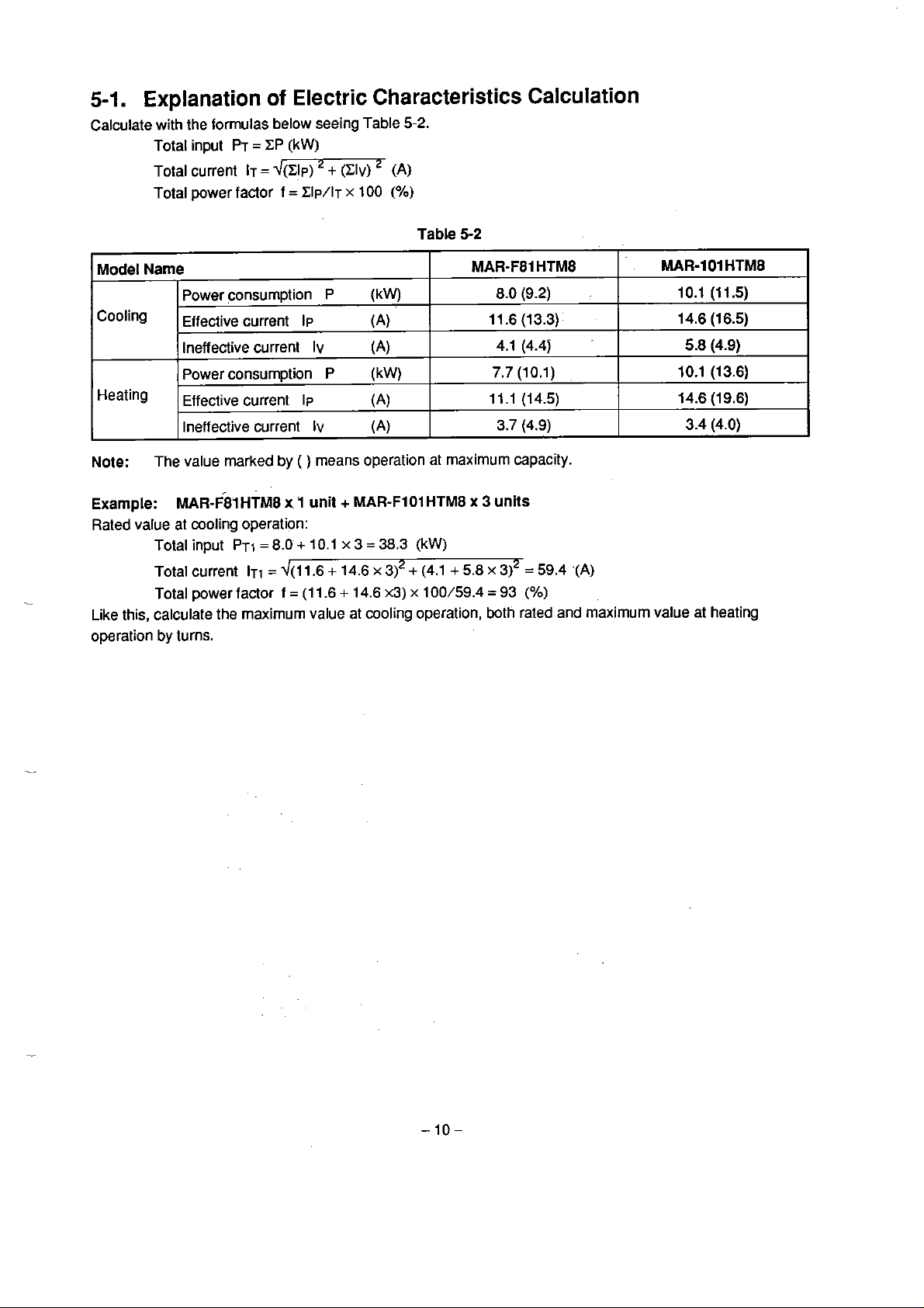
5-1.
Explanation
of
Electric Characteristics Calculation
Calculate with the formulas below seeing Table
Totat input
Total current
Total power factor
PT
=
CP
IT
=
~(CIP) + (CIv)
(kW)
f
=
Clp/l~
x
100
(A)
(Oh)
5-2.
Table
5-2
Model
Narne
Power consumption
CoOling
Effettive
Ineffective current
Power consurnption P
Heating
Effettive
Ineffective current
Note:
Exarnple:
Rated
The value marked
MAR-F01HTM8
value at moling operation:
Total input
Total current
Total power factor
Like this, calculate
by
operation
turns.
MAR-F81 HTM8
+
x
5.8
8.0 (9.2)
11.6 (13.3)
4.1
(4.4j
7.7
(10.1)
11.1
(14.5)
3.7
(4.9)
3
units
x
3)2
=
59.4
=
93
(%)
.(A)
P
(kW)
current
IIJ
IV
(A)
(A)
(kW)
current lp
Iv
by
(
)
means operation at rnaximum capacity.
x
1
unit
PT~
=
8.0 + 10.1 x 3 = 38.3
ITI
=
d(11.6 + 14.6
f
=
(1 1.6 + 14.6
the
maximurn value at cooling operation, both rated and maximurn value al heating
(A)
(A)
+
MAR-FlOlHTM8
(kW)
x
312
+
(4.1
x3)
x
100/59.4
MAR-101
10.1
14.6 (16.5)
5.8
10.1 (13.6)
14.6
3.4
HTMB
(l
1.5)
(4.9)
(19.6)
(4.0)
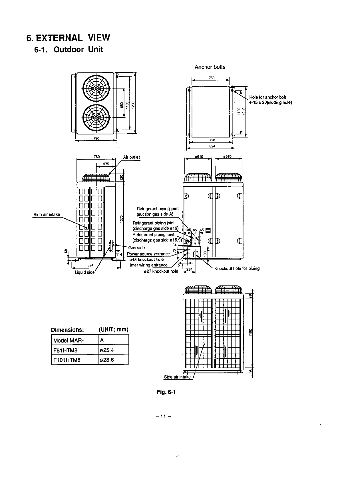
6.
EXTERNAL
VIEW
6-1.
Side
air intake
Outdoor
Unit
750
Air
outlet
Anchor
boiis
for
anchor bolt
x
20(slotting hole)
Dimensions:
Model
MAR-
(UNIT:
I
A
mm)
Fig.
6-1
'
piping
To indoor uni1
To indooX1
A
To indoor unii
To indoor uni1 B To outdwr uni1
Electric
parts
box
Refri ant piping joint (Ilare)
Liqui
A-TO
To indoor uni1 B To indoor unit
=or unx Toxdoor unit
C
Note: Please install
e019
D
Fig. 6-2
hole for
Oval
hanging bolt
4
100 or more
A
I
I
-F
Slit for hanging bolt It is indispensable for test run and servicing.
-1
\
1
I
,I
-
Outdoor uni1 side
M
Or
Electric paris box or more
1
Note: Make an inspection opening at the sp~ified p"..
450rnm x 450rnm over
Suction gas side
Outdoor uni1 sidel
or
Neciri!= 500
g
-
I
Note: Make an inspeciion opening ai the specified place.
Il is indispensable for test run and servicing.
0
28.6
more or more
Indoor unit side
or more
450 x 450 inspection opening
installation space
100 or more
I
T
Indoor unit side
500
or more
450 x 450 ins~ection
installation siace
iring entrance
igerant piping joint (Ilare)
Discharge gas side 0 19
I
opening
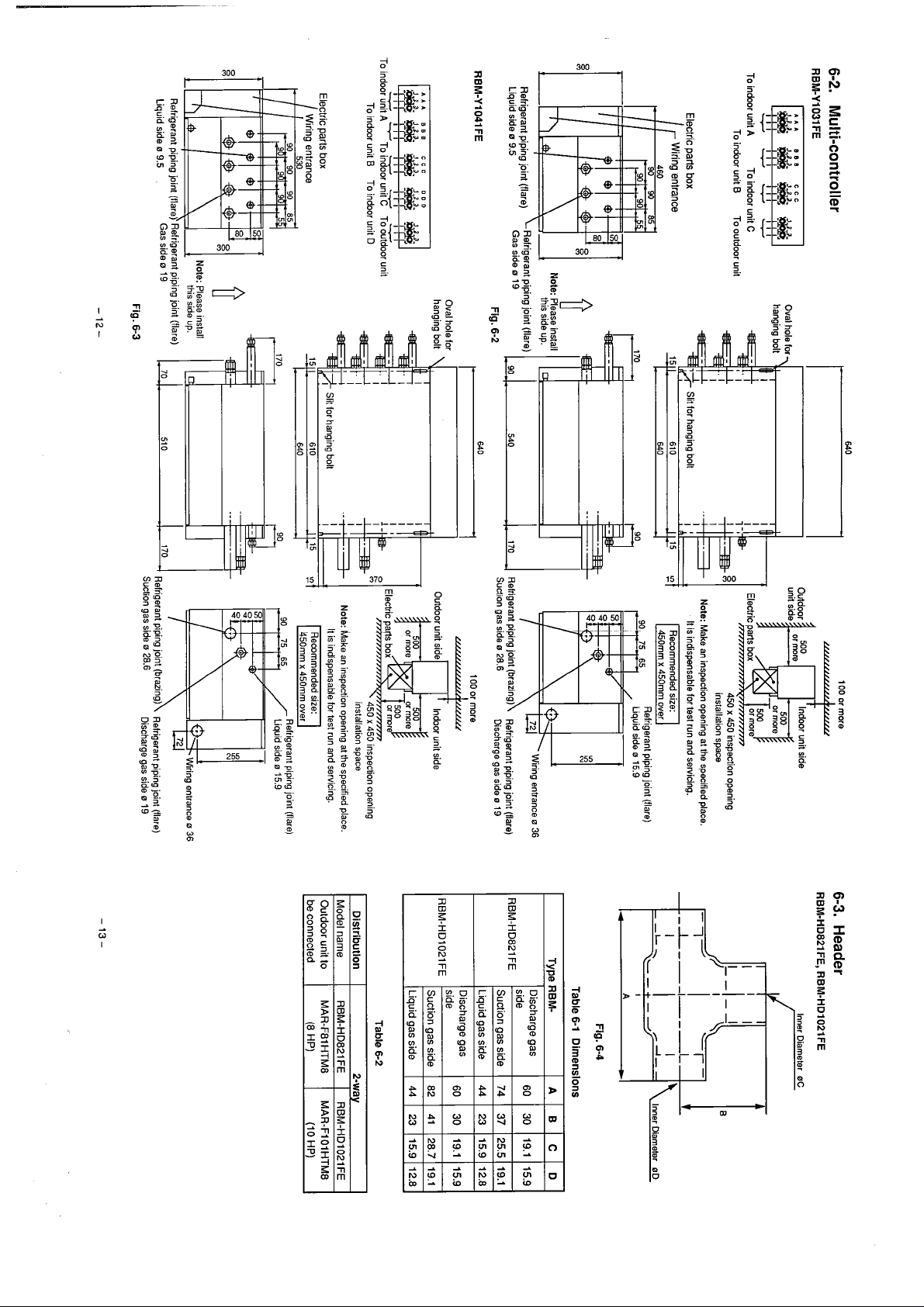
6-3.
RBM-HD821FE, RBM-HD1021FE
1-
0
36
O
O
Liquid side 0 9.5
Fig. 6-3
450mm x 450rnm over
Suction gas side
0
28.6
Discharge gas side 0 19
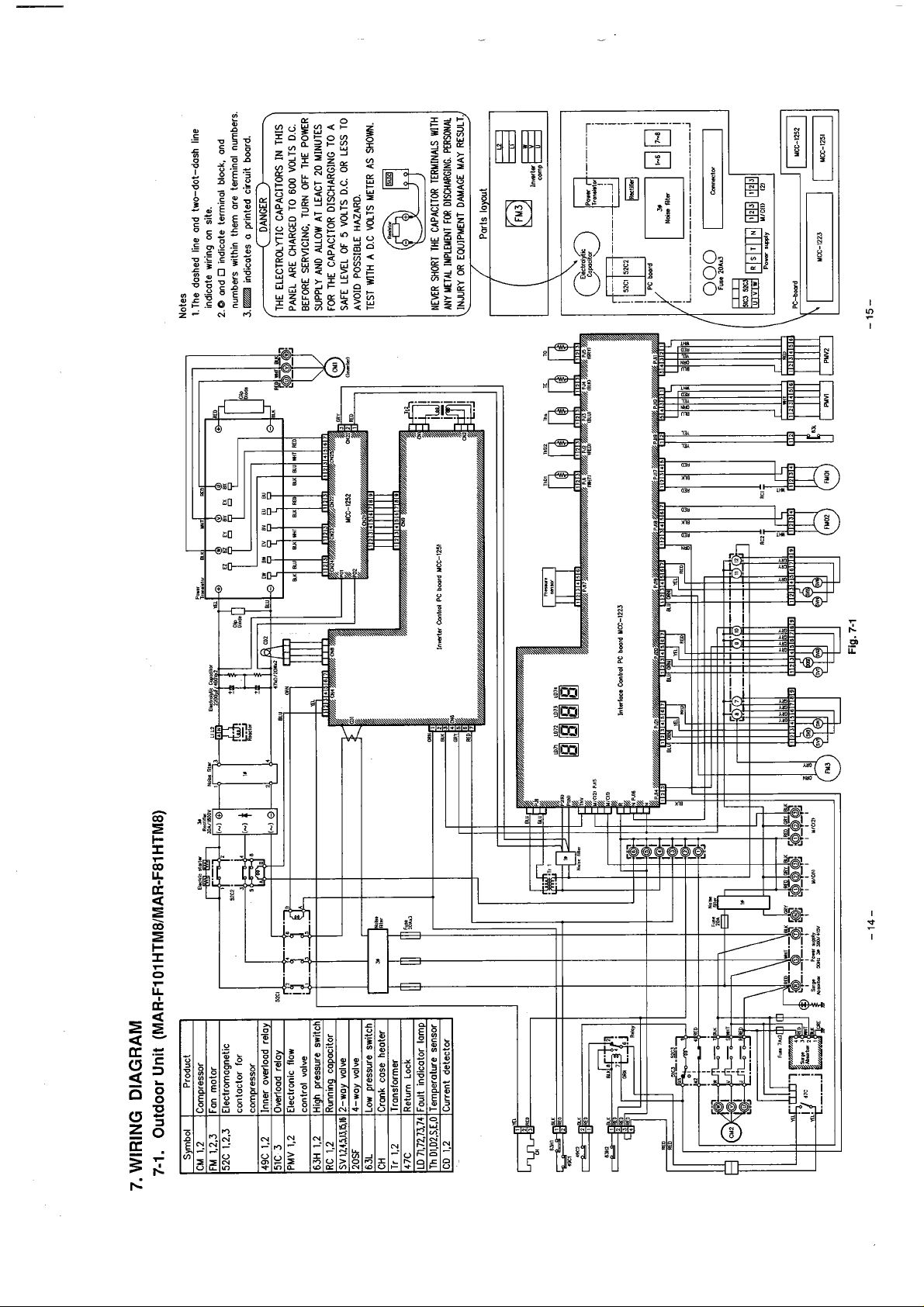
7.
WIRING DIAGRAM
7-1.
Outdoor
Unit
(MAR-F1
01
HTMBlMARF81HTM8)
Inarlor
Cmtrol
PC bmrd
YCC-1251
Inlaloce Cmlrd
-14- -15-
PC
bmid
Fig.
YCC-1223
7-1
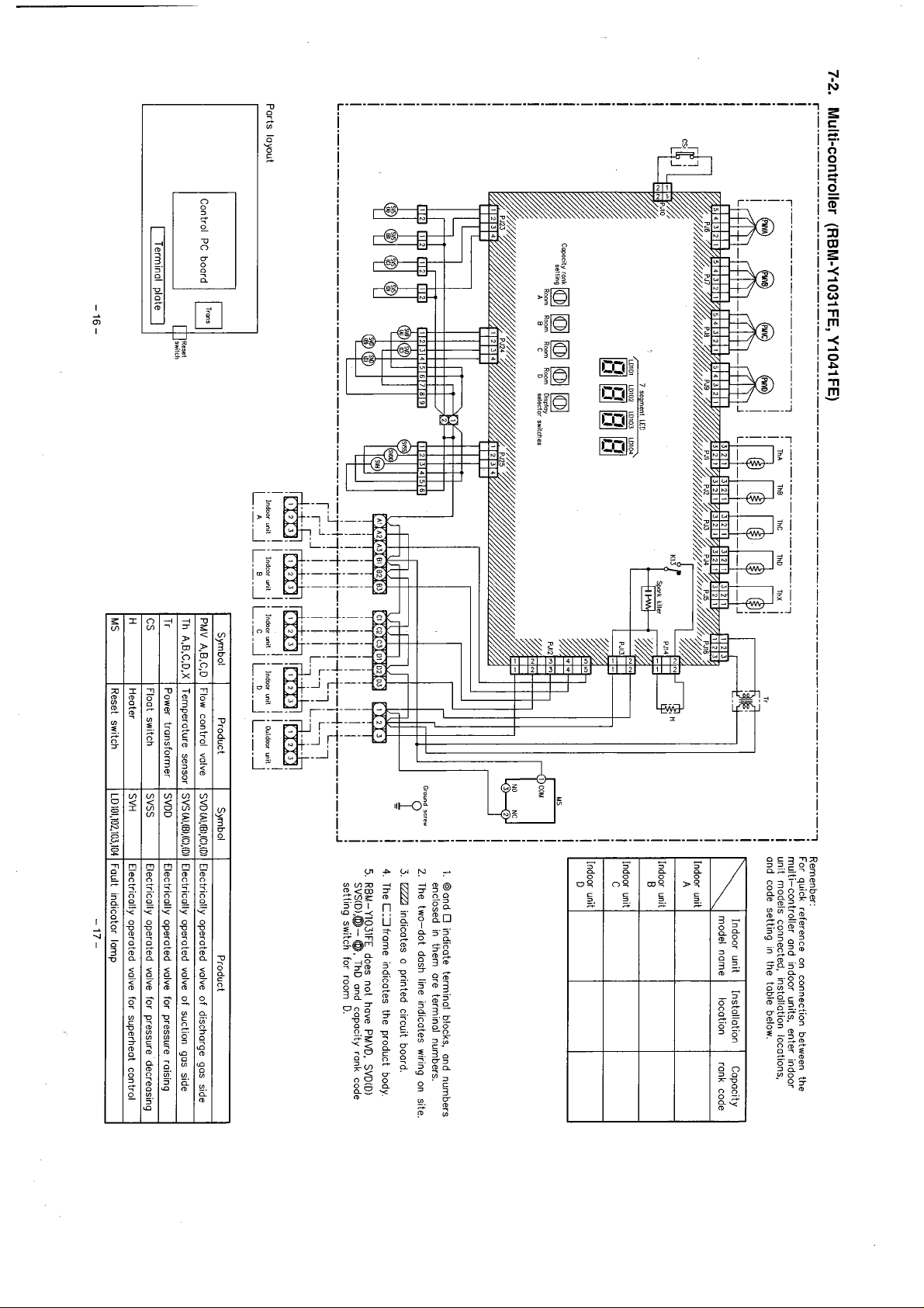
Multi-controller
r----------'------------------------------------------------------------------------
(RBM-Y1031 FE, Y1041 FE)
!
Rernenber:
7
For quick reference on connection between the
!
multi-controller ond indoor units. enter indoor
unit models connected. instollotion locations,
ond code setting in the toble below.
1. Oond
O
enclosed in them ore termino1 numbers.
2.
The two-dot dosh line indicotes wiring on site.
3.
EZZJ
indicates o printed circuit boord
4.
The C13frome indicotes the product body
5.
RBM-Y1031FE does not have PMVD. SVD(D)
SVS(D),@-
setting switch for room
Ports layout
Control
PC
boord
m
[
Termina1 plote
8
unii
8
I
i
L.B.A
a
Indoor
L.L.A
]
Indaor
,m
unit
i i
Indoor
L.2.J
8 8 8 8
unii
i
i
L-0-1
Syrnbol
PMV A,B.C.D
Th A.B.C,D,X
Tr
CS
H
MS
lndoar
unii
i i
Ouldcor
L--.l
Product
Flow control volve
Temperature sensor
Power tronsforrner
Float switch
Heater
Reset switch
unit
:
Symbol
SVDiA).IBI.IC).(DI
SVSiAl.(BI,(C).(DI
SVDD
SVSS
SVH
LD101.102.103.104
Electricolly operoted volve of discharge gas side
Electrically operoted volve of suction gas side
Electricolly operoted valve for pressure raising
Electricolly operoted valve for pressure decreasing
Electrically operated valve for superheot
Foult indicotor lomp
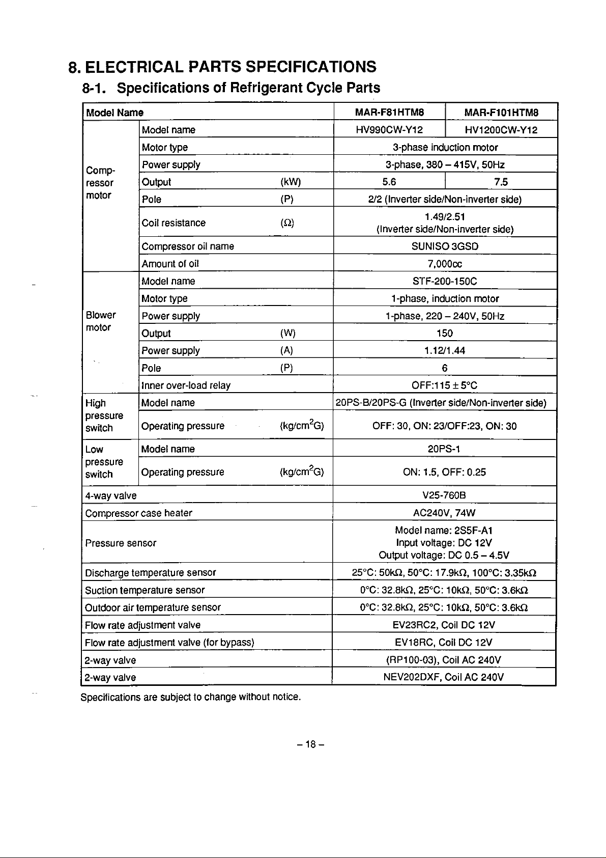
8.
ELECTRICAL
PARTS
SPECIFICATIONS
8-1.
Model
Cornpressor
motor
Blower
rnotor
Specifications
of
Refrigerant
Name
Model name
Motor type
Power supply
Output (kW)
Pole
Coil resistance
Cornpressor oil narne
Arnount of oil
Model narne
Motor type
Power supply
Output
Power supply (A)
Pole
Inner over-load relay
(p)
(Q)
(W)
(p)
Cycle
Parts
MAR-F81
HV990CW-YI 2
HTM8
3-phase induction motor
3-phase, 380 - 415V, 50Hz
5.6
212 (Inveder sidelNon-inverter side)
1.4912.51
(Inverter sidelbion-inverfer side)
SUNISO 3GSD
7,000~~
STF-200-150C
l
-phase, induction motor
1-phase, 220
1.12/1.44
OFF:115 f 5OC
MAR-FIO1
HV1200CW-Y12
-
240V, 50Hz
150
6
HTM8
7.5
High
pressure
switch
Low
pressure
switch
4-way valve
Compressor case heater
Pressure sensor
Discharge temperature sensor
Suction temperature sensor
Outdoor air temperature sensor
Flow rate adjustment valve
Flow rate
2-way valve
2-way valve
Specifications are subject to change without notice.
Model name
Operating pressure (kg/crn2~)
Model narne
Operating
adjustment valve (for bypass)
pressure (kg/cm2~)
20PS-Bl20PS-G (Inverter side/Non-inverter side)
OFF: 30, ON:
ON: 1.5, OFF: 0.25
Model narne: 2S5F-A1
Input voltage: DC 12V
Output voltage:
25°C:
50W,
0°C: 32.8kR, 25°C: 10k2,5O0C: 3,6m
0°C: 32.8kLt25"C: IOkQ, 50°C:
EV23RC2, Coil DC 12V
EV18RC, Coil DC 12V
(RP100-03), Coil
NEV202DXF, Coil AC 240V
23/OFF:23,
20PS-1
V25-760B
AC240V, 74W
DC
50°C: 17.9kQ, 100°C:
ON:
0.5 - 4.5V
AC
240V
30
3.35kS1
3.6U
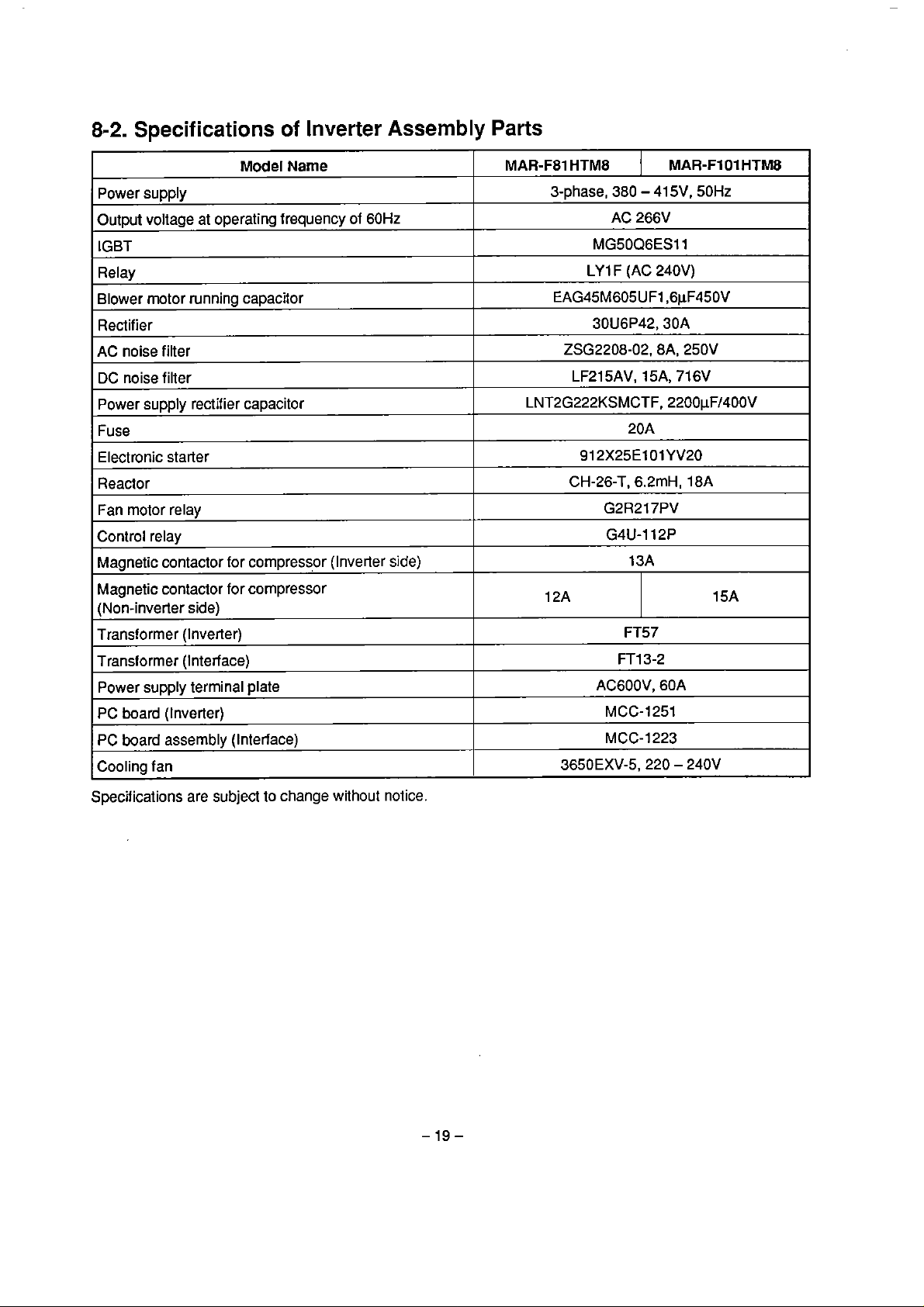
8-2.
Specifications
of
Inverter
Assembly
Parts
Model
Power supply
Output voiiage at operating frequency of
IGBT
Relay
Blower motor running capacitor
Rectifier
AC noise filter
DC noise filter
Power supply rectifier capacitor
Fuse
Electronic starter
Reactor
Fan
rnotor relay
Control relay
Magnetic contactor for
Magnetic contactor for compressor
(Non-inverler side)
Transformer (lnverter)
Transformer (Interface)
Power supply
PC
board (tnverter)
termina1 plate
Narne
compressor (Inverter
60Hz
side)
MAR-FS1
HTM8
3-phase,
EAG45M605UF1,6pF450V
ZSG2208-02,8A, 250V
LNT2G222KSMCTF, 2200pFl4OOV
12A
380
AC
MG50Q6ES11
LY
1 F (AC 240V)
30U6P42,30A
LF215AV, 15A, 71
912X25ElOlYV20
CH-26-T, 6.2mH, 18A
G2R217PV
G4U-112P
FT13-2
ACGOOV, 60A
MCC-1251
-
41 5V, 50Hz
266V
20A
13A
FT57
MAR-Fl 01
6V
HTM8
15A
PC
board assembly (Interface)
Cooling
Specifications are subject to change without notice.
fan
MCC-1223
3650EXV-5,220 - 240V
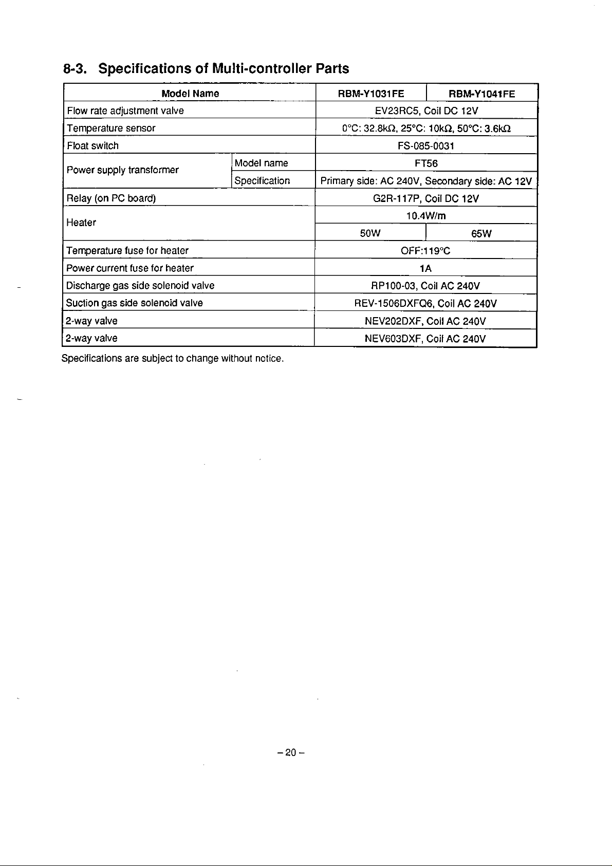
8-3.
Specìfications of Multi-controller
Parts
Model
Flow rate adjustment valve
Temperature sensor
Float switch
Power supply transformer
Relay (on
Heater
Temperature fuse for heater
Power current fuse for heater
Discharge gas side solenoid valve
Suction gas side
2-way valve
2-way valve
Specifications are subject to change without
PC
board)
solenoid valve
Name
Model narne
Specif ication
notice.
RBM-Y1031
0°C:
Prirnary side: AC 240V, Secondary side:
50W
REV-1506DXFQ6, Coil
FE
EV23RC5, Coil DC 12V
32.8m.
NEV202DXF, Coil
NEV603DXF, Coil AC 240V
25OC: 1 OkR, 50°C:
FS-085-0031
FT56
G2R-117P,
10.4W/m
0FF:11S0C
RP100-03, Coil
Coil
I
1 A
AC
RBM-Y1041
DC
12V
65W
240V
AC
240V
AC
240V
3.6kn
FE
AC
12V
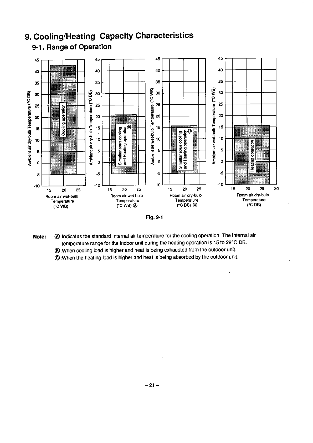
9.
CoolinglHeating Capacity Characteristics
9-1.
Range
15
Room
Temperature
('C
of
20 25
air wet-bulb
WB)
Operation
15
Room
20
25
air wet-bulb
Temperature Temperature
("C
WB)
@
15
Room
("C
20
air
dry-bulb
DB)
@
25
15
20
Room air dry-bulb
Temperature
('=C
DB)
25
30
Note:
Fig.
9-1
@:lndicates the standard internal air temperature
temperature range for
@:When cooling load
@:~hen
lhe
heating load
the indoor unit during the heating operation
is
higher and heat is being exhausted
is
higher and heat is being absorbed
for
the
cooling
from
operalion.
is
15
The
to
the outdoor una.
by
the outdoor unit.
internal air
28°C
DB.
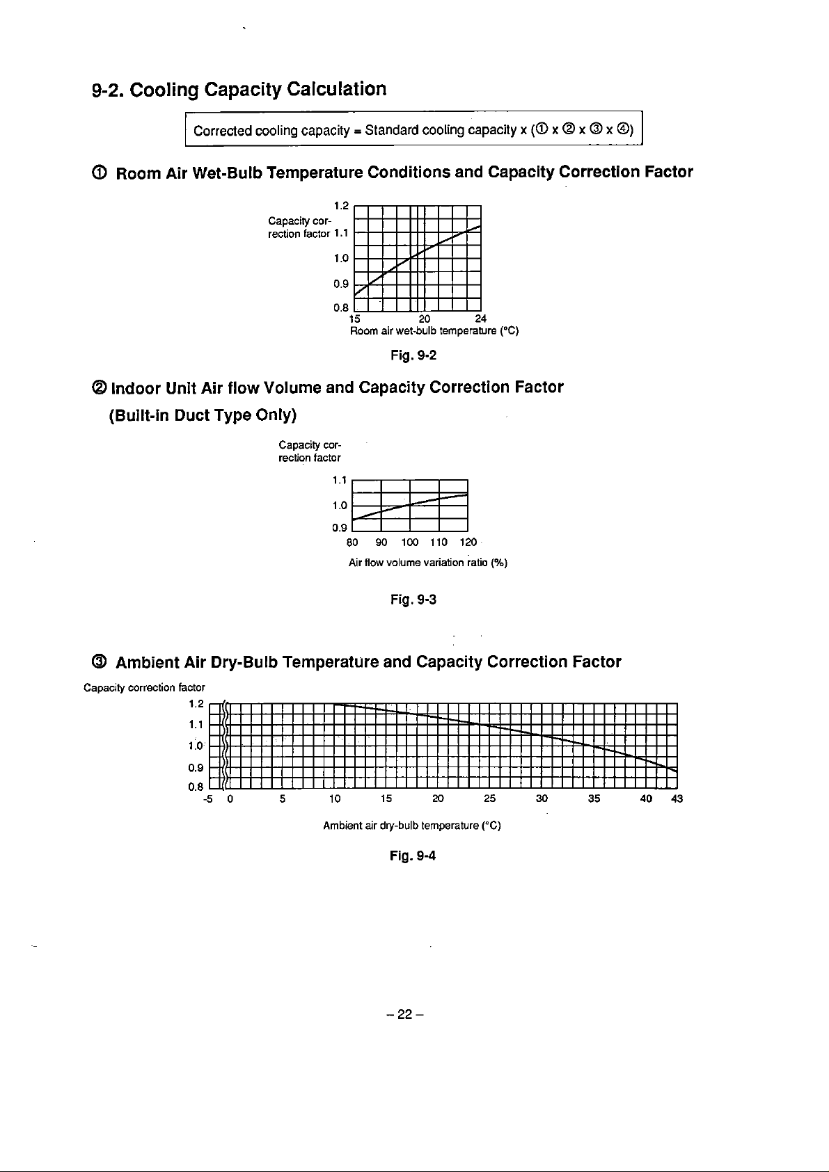
9-2.
Cooling Capacity Calculation
Corrected
a
Room Air Wet-Bulb Temperature Conditions and Capacity Correction Factor
@
Indoor Unit
(Built-in
Air
Duct
cooling capacity = Standard
1.2
flow
Capaciry
rection
Volume
cor-
factor
1
1
0.9
0.8
and Capacity Correction Factor
Type Only)
Capacity correction factor
cooling
.l
capacity
.o
15
Room air wet-bulb temperature
Fig.
20
9-2
24
("C)
x
(a
x
@ x @
x
@)
Air
flow
volume variation ratio
Fig.
9-3
@
Ambient Air Dry-Bulb Temperature and Capacity Correction Factor
Capacity correction factor
Ambient air
dry-bulb
Fig.
temperature
9-4
(%)
("C)
@
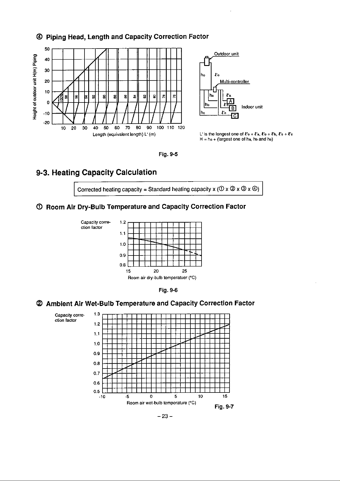
Piping
Head,
Length and Capacity Correction Factor
&'r
I
ho
Outdoor unit
I
P'o
unit
9-3.
Heating
@
Room Air
10 20 30
Capacity
Corrected
Dry-Bulb
Capacity correction
40
50
60
70
80
Length (equivalent length)
Calculation
heating
factor
capacity = Standard
Temperature and
1.2
1.1
0.8
15 20 25
Room air dry-bulb temperatuer
90
100 110 120
L'
(m)
Fig.
9-5
heating
Capacity
Fig.
9-6
L'
is
the longest one of
H
=
ho
+
(largest one of
capacity
x
(a
x Q x
Correction Factor
("C)
4'0
@
ha,
x
+l'a,
hb and
@)
O'O
+
hc)
Eb,
4'0
+
O'C
@
Ambient Air Wet-BuIb Temperature and Capacity Correction Factor
Capacity
ction factor
corre-
1.3
1.2
0.5
-1
O
-5
Room
O
air wet-bulb temperature
5
10 15
("C)
Fig.
9-7
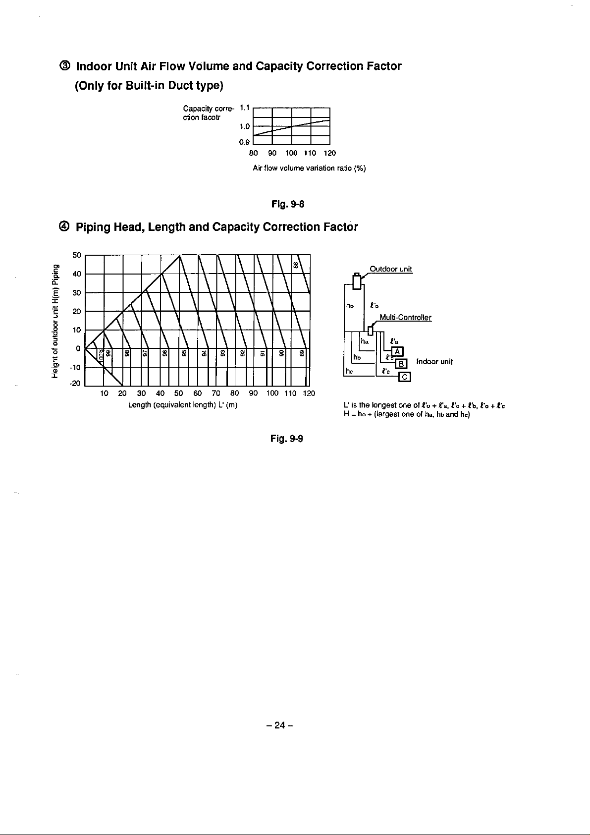
@
Indoor Unit Air Flow Volume and Capacity Correction Factor
(Only for Built-in Duct type)
@
Piping
Capacity
ction
facotr
corre-
1.1
1
.o
0.9
80
90 100
Air flow volume variation ratio
110
l20
(%)
Fig. 9-8
Head, Length and Capacity Correction Factor
7
hc
Outdoor
unit
Multi-Controller
O'c
Indoor unit
Length (equivalent length)
L'
(m)
Fig.
9-9
C
is
the longest one of
H
=
ho
+
(largest one of
2'0
ha,
+
l'a,
hb
4'0
and
+
hc)
Ib,
I'o
+
O's
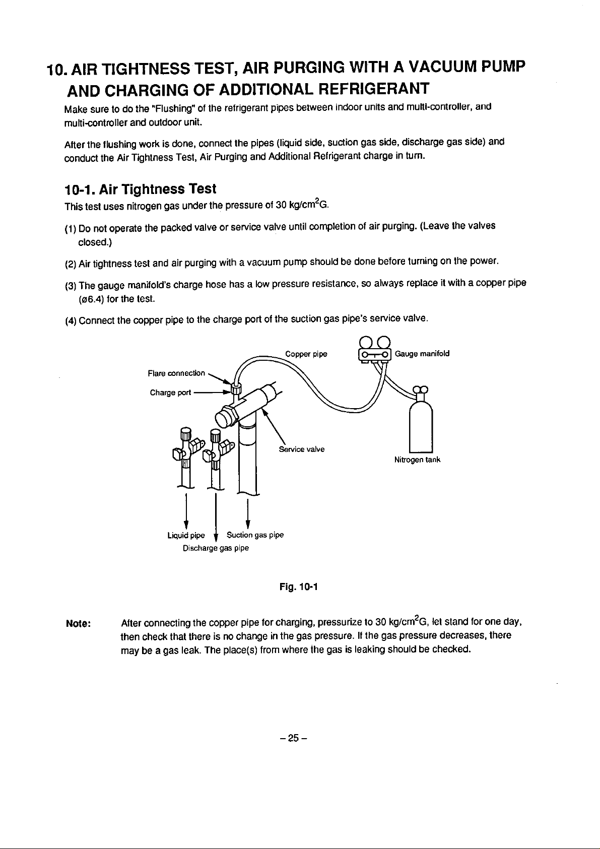
10.
AIR TIGHTNESS
TEST,
AIR
PURGING
WITH
A
VACUUM
PUMP
AND
Make sure Lo
multi-controller and outdoor unit.
Aiter the flushing
conduct the Air Tightness Test, Air Purging and Additional Refrigerant charge in turn.
10-1.
This test uses nitrogen gas under the pressure of
(1)
(2)
(3)
(4)
CHARGING
do
the "Flushing" of the refrigerant pipes between indoor units and multi-controller,
work
is done, connect the pipes (liquid side, suction gas side, discharge gas side)
Air
Tightness
Do
not
operate the packed valve or service valve until completion of air purging. (Leave the valves
closed.)
Air tightness test and air purging with a vacuum pump should be done before turning on the power
The
gauge rnanifold's charge hose has a
(06.4)
for the test.
Connect the copper pipe to the charge port
OF
Test
ADDITIONAL
30
kg/crn2~.
low
pressure resistance,
of
the suction gas pipe's service valve.
REFRIGERANT
so
always replace it
with
and
and
a
copper pipe
Note:
Liquid
pipe
Discharge
After connecting the copper pipe for charging, pressurize
then check that there
may be
a
gas leak. The piace(s) from where the gas is leaking should be checked.
Suction
gas
pipe
gas
pipe
Fig.
10-1
is
no change in the gas pressure.
to
30
kg/cm2~,
If
the gas pressure decreases, there
let stand for one day,
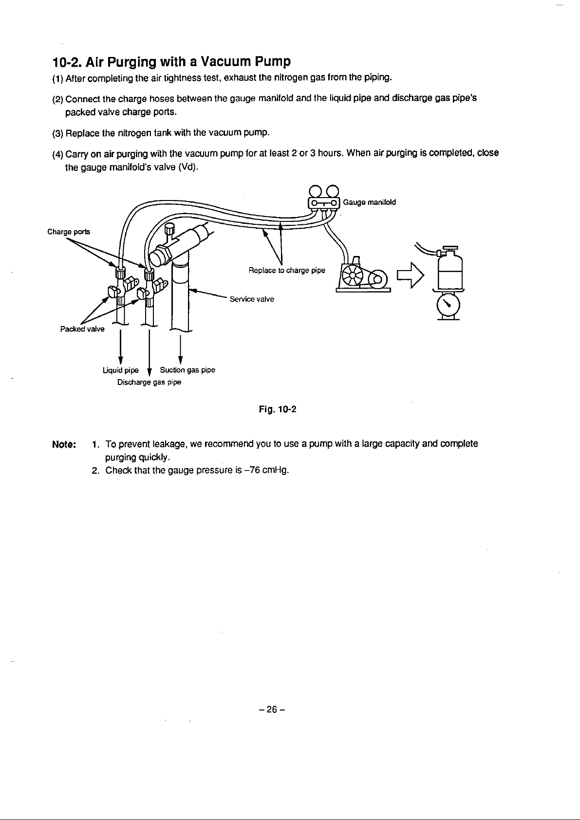
10-2.
(1)
(2)
(3)
(4)
Air
Purging
After completing the air lightness test, exhaust the nitrogen gas from the piping.
Connect the charge hoses behveen the gauge manifold and
packed valve charge
Replace the nitrogen tank with lhe vacuum pump.
Carry on air purging with the vacuum pump for at least 2 or 3 hours.
t
he gauge manifold's valve
with
ports.
a
Vacuum
(Vd)
.
Pump
the
liquid pipe and discharge gas pipe's
When
air purging is completed, close
Note:
Liquid
pipe t Suction
Discharge
1.
To prevent leakage, we recommend you to use a pump with a large capacity
purging
2.
Check that the gauge pressure
gas
quickly.
pipe
gas
pipe
is
-76
Fig.
10-2
cmHg.
and
complete

10-3.
(l)
(2)
(3)
(4)
Additional
Reptace the vacuum pump with the refrigerant tank, charge the stipulated arnount of refrigerant, and then
open both packed valve and service valve fully. If additional charge is needed, conduct the following.
Switch the charge hose lo the suction gas pipe's service valve charge port (dotted lines 4 solid tines, one
charge
Attach the charge hose lightly to the suction gas pipes service valve charge
loosen the refrigerant tank's valves (Va and
charge
Next, tighten
specified amount of refrigerant.
refrigerant
hose as shown in Fig.
hose
is
the
in
gas form from the low pressure side lo supply the specified amounl.
Refrigerant
10-3).
expelled by the refrigerant.
hose fully, then loosen the service valve and use the pressure in the tank to add the
Il not enough refrigerant can be added, operate the unit and
Charging
Vb).
The air in the lank's
Low
Charge hose
pressure
port
at first and slightly
gas
hose, gauge rnanifold and
Gauge
manifold
draw
in the
Lquid pipe
Discharge
t
gas
Suction
pipe
gas
pipe
--2.
Fig.
-2.
10-3
.
\
9)
Gas
Refrigerant
5kg
tank
Spring
scale
gas
(20kg)
11.
PIPING
LENGTH
AND
ADDITIONAL
REFRIGERANT
AMOUNT
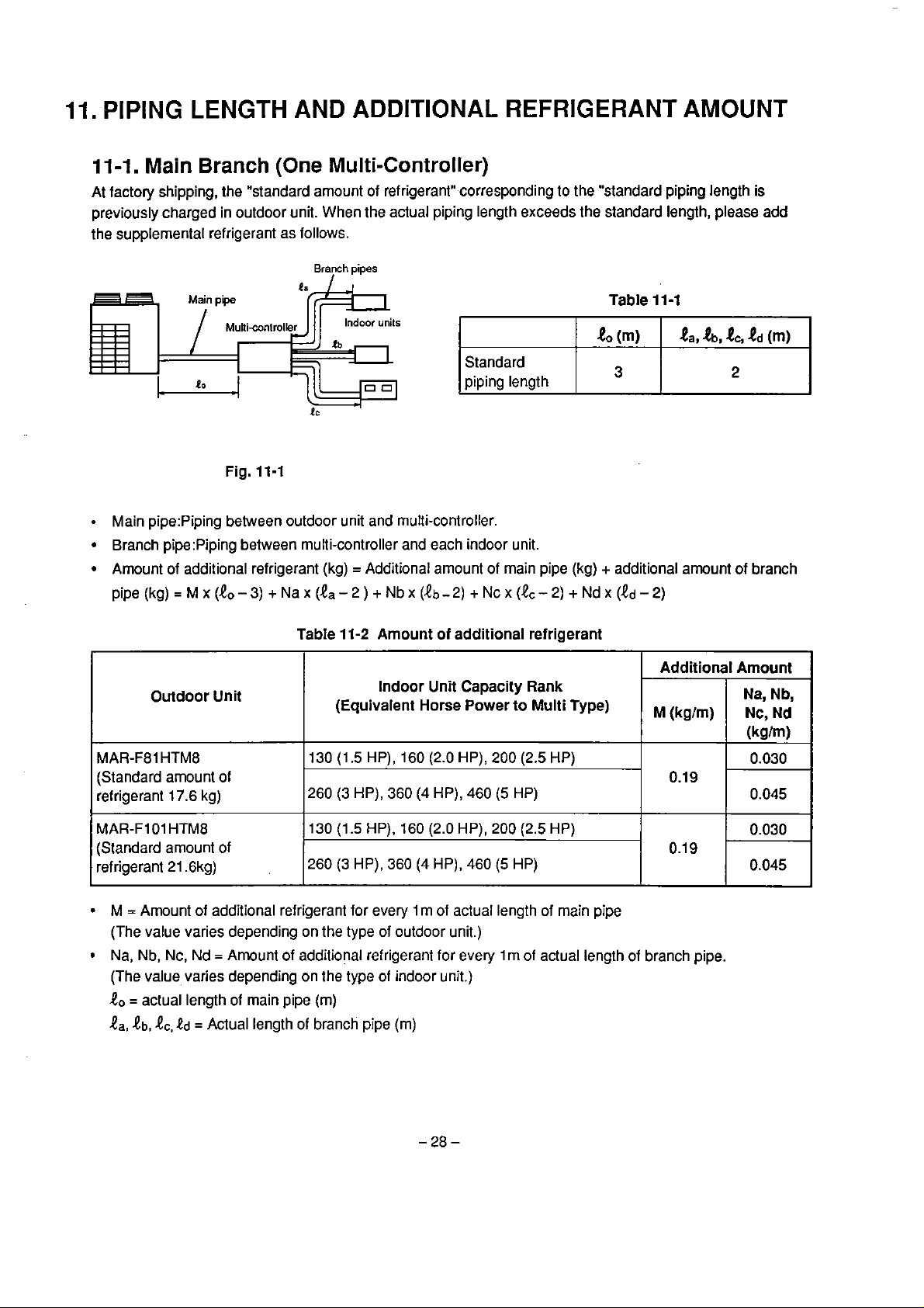
11-1.
At factory shipping, the "standard arnount of refrigerant" corresponding to the "standard piping length
previously charged in outdoor unit. When the actual piping length exceeds the standard length, please add
the supplemental refrigerant as follows.
Main
Main pipe:Piping between outdoor unit and multi-controller.
Branch pipe:Piping between multi-controller and each indoor unit.
Arnount of additional refrigerant (kg) = Additional amount of main pipe
pipe (kg)
Branch
Fig. 11-1
=~x(e,-3)
(One
+~ax
Multi-Controller)
Branch
(1,-2)
pipes
+Nbx
(lb-2) +Ncx(&-2) +Ndx (ed-2)
Table
11
-1
(kg)
+
additional amount of branch
is
Table
11-2 Amount of additional refrigerant
Outdoor Unit
MAR-F81
(Standard arnount of
refrigerant
MAR-Fl
(Standard arnount of
refrigerant 21.6kg)
M = Arnount of additional refrigerant for every
(The value varies depending
Na,
(The
t,,
HTMB
17.6
kg)
O1
HTM8
Nb,
Nc,
Nd
=
Amount of additional refrigerant for every l m of actual length of branch pipe.
value, varies depending on the type of indoor unit.)
= actual length of main pipe (m)
tb,
&,Od
=
Actual length
(Equivalent Horse Power
130
(1.5
HP), 160 (2.0 HP), 200 (2.5 HP)
260 (3HP), 360 (4HP),460(5 HP)
130
(1.5
HP),
260
(3
HP),
on
the type of outdoor unit.)
of
branch pipe (m)
Indoor
Unit
Capacity Rank
160 (2.0 HP), 200
360
(4
HP),
l
m
of actual length of rnain pipe
460
(5
to
(2.5
HP)
Multi Type)
HP)
Additional Arnount
Na,
,,,,
(kg,m,
0.19
0.1
9
Nc,
(kglm)
0.030
0.045
0.030
0.045
Nb,
Nd
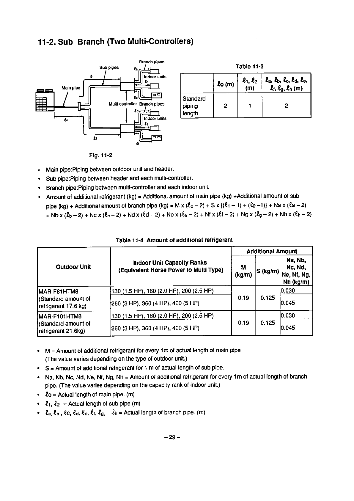
11-2.
Sub
Main pipe:Piping between outdoor unit and header.
Sub pipe:Piping between header and each rnulti-controller.
Branch pipe:Piping between multi-controller and each indoor unit.
Arnount of additional refrigerant (kg) = Additional amount of main pipe (kg) +Additional amount of
pipe
(kg)
+~bx(8b-2)+~~x(e,-2)+~d~(id-2)+~e~(8,-2)+~f~(tf-2)+~g~(Q~-2)+~h~(!h-2)
Branch
Pipe
(Two
Sub
pipes
Multi-Controllers)
Branch
pipes
t
~ulli-conirolkr
Fig.
l
1-2
+
Additional amount of branch pipe (kg)
Bych
pipes
=
M
Standard
piping
length
x
(10
-
2)
+
S
x
2
{(ti
Table
-
1)
11
-3
e,,
(m)
+
P,,
e2
&,&,eh
l
(e2
-l)} + Na x (ta - 2)
.tb,
4,
2
&,
te,
(m)
sub
Table
11-4
Amount of additional refrigerant
Outdoor
MAR-F81 HTM8
(Standard arnount of
refrigerant
MAR-FIO1
(Standard amount of
refrigerant
M
=
Arnount of additional refrigerant for every 1m ot actual length of main pipe
(The value varies depending on the type
S
=
Amount of additional refrigerant far 1 m o1 actual length of sub pipe.
Na, Nb, Nc.
pipe. (The
40
=
Aclual length of main pipe.
41,
t2
la,
tb
,
Unit
130 (1.5 HP), 160 (2.0 HP), 200
17.6
kg)
HTM8
21.6kg)
Nd,
Ne,
value varies depending on the capacity rank of indoor unit.)
=
Actual length of sub pipe (m)
h,
td,
te,
ef,
260 (3 HP),
130 (1.5 HP), 160
260
Nf,
Ng, Nh = Amount of additional refrigerant
.eg,
eh
Indoor Unit Capacity Ranks
(Equivalent Horse Power to Multi Type)
(2.5
360
(4
HP),
460
(5
HP)
(2.0
(3
HP),
360
(4
of
outdoor unit.)
HP), 200
HP), 460
(5
(2.5
HP)
(m)
=
Aclual length of branch pipe.
(m)
HP)
HP)
for
every
Additlonal Amount
M
(kglm)
0.19
0.19
Im
of actual length of branch
(kg'm)
0.125
0.125
Ne, Nf, Ng.
Nh
0.030
0.045
0.030
0.045
Na, Nb,
Nc, Nd,
(kglm)
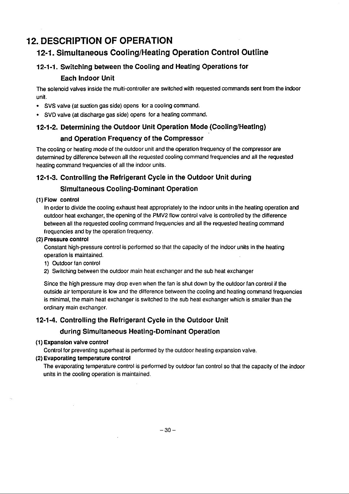
12.
DESCRIPTION
OF
OPERATION
12-1.
Simultaneous CoolingtHeating Operation Control Outline
12-1-1. Switching between the Cooling and Heating Operations for
Each Indoor Unit
The solenoid valves inside the muiti-controller are switched with requested commands sent from the indoor
unii.
SVS
valve (at suction gas side) opens for a cooling command.
SVD
valve (al discharge gas side) opens for a heating command.
t
2-1-2.
Determining the Outdoor Unit Operation Mode (CoolingIHeating)
and Operation Frequency of the Compressor
The cooling or heating mode of the outdoor unit and Ihe operation frequency of the compressor are
determined
heating command frequencies of
by
difference between al1 ihe requested cooling command frequencies and al1 the requested
al1 the indoor units.
12-1-3. Controlling the Refrigerant Cycle in the Outdoor Unit during
SrmuItaneous Cooling-Dominant Operation
(I
)
FIOW
contro1
In order to divide the cooling exhaust heat appropriately to the indoor units in the heating operation and
outdoor heat exchanger, the opening of the
between
frequencies and by the operation frequency.
(2)
Pressure contro1
Constant high-pressure control is performed so that the capacity of the indoor units in the heating
operation is maintained.
1)
2)
al1 the requested cooling comrnand frequencies and al1 the requested heating command
Outdoor fan control
Switching between the outdoor main heat exchanger and the sub heat exchanger
PMV2
flow control valve is controlled by the difference
Since the high pressure
outside air temperature is low and the difference between the cooling and heating command frequencies
is
minimal, the main heat exchanger is switched to the sub heat exchanger which is srnaller than the
ordinary rnain exchanger.
12-1
-4.
Controlling the Refrigerant Cycle in the Outdoor Unit
may
drop even when the fan
is
shut down by the outdoor fan control
if
the
during Simultaneous Heating-Dominant Operation
(1)
Expansion valve control
Control for preventing superheat is
(2)
~vaporaiing, temperature control
The evaporating temperature control
units in the cooling operation is maintained.
periormed
is
by
the outdoor heating expansion valve.
performed by outdoor fan control so that the capacity of Ihe indoor

(3)
Swltching between outdoor expansion
When there is a minimal
by
the outdoor heat exchanger
the
flow. This results in capillary control being selected.
differente
is
between the cooling and heating frequencies and the heat absorption
low,
the
valve
control and capillary control
expansion valve is no longer capable of controlling adequately
12-2.
12-2-1.
(1)
PMV
SVS
SVD
Functions
Multi-controller
Valve functions
Symbol
(A,
B,
C,
(A,
B,
C,
(A,
8,
C,
svss
SVDD
SVH
and
Operations
Name of Valve
Flow rate contro1 valve
D)
Suction gas valve
D)
Discharge gas valve
D)
Pressure reducing solenoid
valve
Pressure increasing solenoid
valve
Superheat solenoid valve
of
Solenoici
This opens to the extent
and performance required of the indoor units in each
system.
Opens when cornrnands from the indoor units in each
system
Opens when cornrnands from the
system call for heating.
Opens when number of units in heating operation
reduced (heating 4 shutdown or cooling).
Opens when def rosting
Opens while
Opens when number
increased (shutdown or cooling + heating).
Opens while
discharge pipe from being blocked.
Opens when unit in cooling operation
Valves
Descriptlon of Function
corresponding to
call
lor cooling.
indoor units in each
starls.
oil
recovery is controlled in cooling.
o1 units in heating operation is
contro1 is performed to prevent liquid in
is
the
presenl.
capacity
is
(2)
Valve operatlons
Outdoor
Operation Mode
Shutdown
During operation
Indoor
Shutdown, fan
Shutdown, fan
Cooling
Cooling
Heating
Heating therrno-contro1 OFF
Operation
Iherrno-contro1
Mode
OFF
SVD
OFF
OFF
OFF
OFF
ON
ON
SVS
OFF
ON
ON
ON
OFF
OFF
PMV
(Normal)
Fully closed
Futly closed
Rated opening
Fully closed
Rated opening
Fully closed

12-2-2.
(1)
Valve
Outdoor
functlons
Unit
Symbol
20SF
Name
of
Valve
4-way switching varve
Sub heat exchanger solenoid
valve
Cooling solenoid valve
Outdoor flow control valve
I
solenoid valve
valve
Solenoid valve for capillary
Cooling bypass flow
valve
High-pressure release
solenoid valve
Hot gas bypass solenoid valve
Solenoid valve ior stariup
com~ensation
Gas balance
p--p
control
-
DescrIption
Selects whether outdoor main heat exchanger is to be
used as condenser or evaporator.
OFF: Condenser, ON: Evaporator
Selects whether outdoor main heat exchanger or sub
heat exchanger is to be used.
OFF:
Main exchanger,
Selects whether the sub heat exchanger is going to be
used
or
not,
1
Opens when sub heat exchanger
Opens for cooiing-oniy operations.
L
Controls flow to divide cooling exhaust heal between
indoor units in heating operation and outdoor heat
exchanger during sirnultaneous cooling-dorninant
operations.
Its opening
I
coolingtheating difference.
I
Its opening is adjusted by the adjustrnent signal
frorn the multi-controller.
Opens or closes to select the expansion valve or
capillary tube
coolirig/heating during sirnultaneous operation
(coolinqlheating) under the heating-dorninant operation.
Degree of opening is controlled by discharge and
suction temperature.
Opens and closes with the heat exchange temperature
(TE).
Opens and closes with the pressure and outside air
Opens
side starts up.
Opens when the
when the compressor (No.
is
increased
acmrding to the diflerence of
Inverler cornpressor is shut down.
of
Functlon
ON:
Sub exchanger
in
accordante
is
to be used.
with
2)
at the non-inverter
I
l
I
l

(2)
Valve
operations
Outdoor Operation Mode
Cooling operalion
Heating operation
Simultaneous
coolingdominant
operation
Simultaneous
heat ing-dominant
operation
13.
OPERATIONS
13-1.
Temperature sensor
Multi-Controller
SV13
ON
OFF
OFF
ON
OFF
ON
ON
OFF
ON
ON
ON
C,
SV15
OFF
OFF
OFF
D)
and pseudo saluration temperature (Thx)
20SF
Outdoor
exchanger
Sub
main
heat
heat exchanger
-
Outdoor main heat
exchanger
Sub
heat
exchanger
Expansion valve
Capillary
OF
EACH
According to a temperature difference belween the evaporator outlet
temperature
(1)
Performs the open compensation o1
only, and Cooling-dominant operation)
(2)
Performs the opening degree of
(cooling only, cooling-dominant operation)
SENSOR
(ThA,
B,
SV14
ON
OFF
OFF
OFF
OFF
OFF
OFF
ON
OFF
OFF
OFF
OFF
PMV
the
outdoor flow rate contro1
SV16
OFF
OFF
ON
OFF
OFF
OFF
ON
OFF
ON
in each system. (Cooling
PMVP
-
-
Opening degree
control
Opening degree
control
valve.
-

13-2.
Outdoor
Unit
Pressure sensor
(High pressure)
Suction temperature sensor
(cooling
coolingdOminant 'peration1
heating-dOminant 'peration)
Discharge temperature
sensor (cooling, heating,
coolingdominant,
heating-dOminant Operation)
Outdoor unil heat exchanger
sensor (heating,
heating-dominant operation)
only, heating only,
Determines the frequency of the compressor Inveiter side
status of non-inverter side. (cooling only, heating only, coolingdorninant,
heating-dominant operation)
Controls the outdoor blower. (cooling only, cooling-dorninant operation)
Controls the hot gas bypass
1) Pd < 13kg/cm2~: Open (cooling)
2)
~d<l 7kg/cm2~: Open (cooling-dominant sub heat exchanger
operat ion mode)
Switches the outdoor unit
exchanger operation
Controls the open degrees of PMVl
Operation temperature:
Stops when the suction temperature
to detect the suction temperature abnormality.
Controls open degrees of PMV1 (cooling bypass).
Operation temperature: 11 0°C
Stops when the discharge temperature
discharge temperature abnorrnality.
Multiples the time during TE C -3°C and performs the defrost contro1 after
55
minutes.
Controls the outdoor unit blower.
Controls the high pressure
Opens when
(25
minutes when the Wwer is turned
TE
r
SV2.
main heat exchanger operation and sub heat
(cooling bypass)
20°C
>
40°C
continues for ten minutes due
>130°C due to detect the count
ON
release.
11°C.
and
ONIOFF
for the first time.)
3
Outdoor temperature
High pressure switch
Low pressure switch
Operation pressure:
0.25
kg/crn2~
sensOr
Controls the hot gas bypass
Opens when the outdoor temperature C 0°C
Opens when the outdoor temperature
Controls the outdoor blower.
Identifies whether the forced cooling operation
The forced
temperature
Stops when Pd>
compressor side due to
Stops al1 the operations
abnormality. (Cooling, cooling-dorninant operation)
Stops
al1 the operation after counting
to detect the gas leak abnormality. (Heating, heating-dominant operation)
Ignores the low pressure switch operation. (Defrost operation)
cooling operation
>
25%.
30
kgtcm2G in both of inverter side and non-inverter
SV2.
(10
HP).
e
13°C
(8
HP).
is
performed.
is
performed when the outdoor
detects the high pressure abnormality.
30
seconds after due to detect Ihe gas leak
10
rninutes by the timer counter due

14.
COOLINGIHEATING AUTOMATIC
REMOTE
CONTROLLER
14-1.
Cooling/Heating
Basic variation
rwm
temperature (example)
Automatic
of
Change-Over Operation
Load
Load
variation
variation
n
a
I
-
Cooling
operation
Fig.
0.5deg
14-1
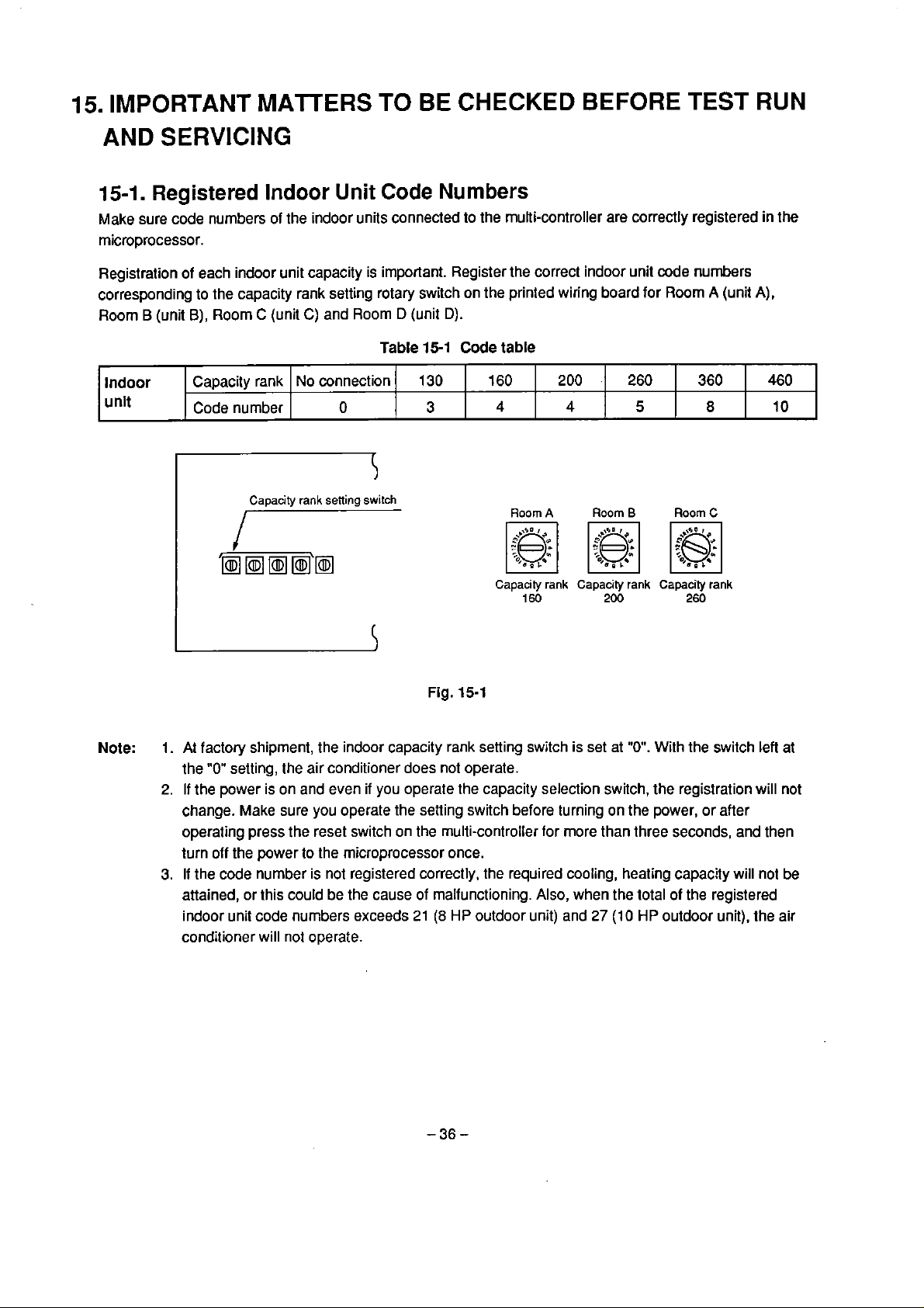
15.
IMPORTANT MATTERS
T0
BE
CHECKED
BEFORE
TEST
RUN
AND
15-1.
Make
rnicroprocessor.
Registralion of each
corresponding to the capacity rank setting
Roorn B (unit
Indoor
unit
SERVICING
Registered
sure code nurnbers of the indoor units connected to the multi-controller are correctly registered in the
B),
Roorn C (unit
Capacity rank
Code number
Indoor
indoor unit capacity is important. Register the correct indoor unit code numbers
Capacity
Unit
Code
rotary switch on the printed wiring board far Roorn A (unit
C)
and Roorn D (unit
Table
No connection
O
rank
sening
switch
Numbers
D).
15-1
Code
130
3
table
160
4
Roorn
A
200
4
.
Room
260
5
B
360
Roorn
8
C
7
Capacity
160
rank
Capacity
200
rank
Capacity
260
rank
A),
460
10
Note:
Fig.
15-1
1.
At factory shipment, the indoor capacity rank setting switch is set at
the
"0"
setting, the air conditioner does not operate.
2.
If
the power is on and even if you operale the capacity selection switch, the registration will not
change. Make
operaling press the reset switch on the multi-controfler for more than three seconds, and then
turn off the power to the microprocessor once.
3.
If
the
code nurnber is not registered correctly, the required cooling, heating capacity will nol be
attained, or this could be the cause of malfunctioning.
indoor unil code numbers exceeds
conditioner will not operate.
sure you operate the setting switch before turning on the power, or after
Also, when the iotal of the registered
21
(8
HP
outdoor
unit)
and
27
"O".
With the switch leit
(10
HP
outdoor unit), the air
at
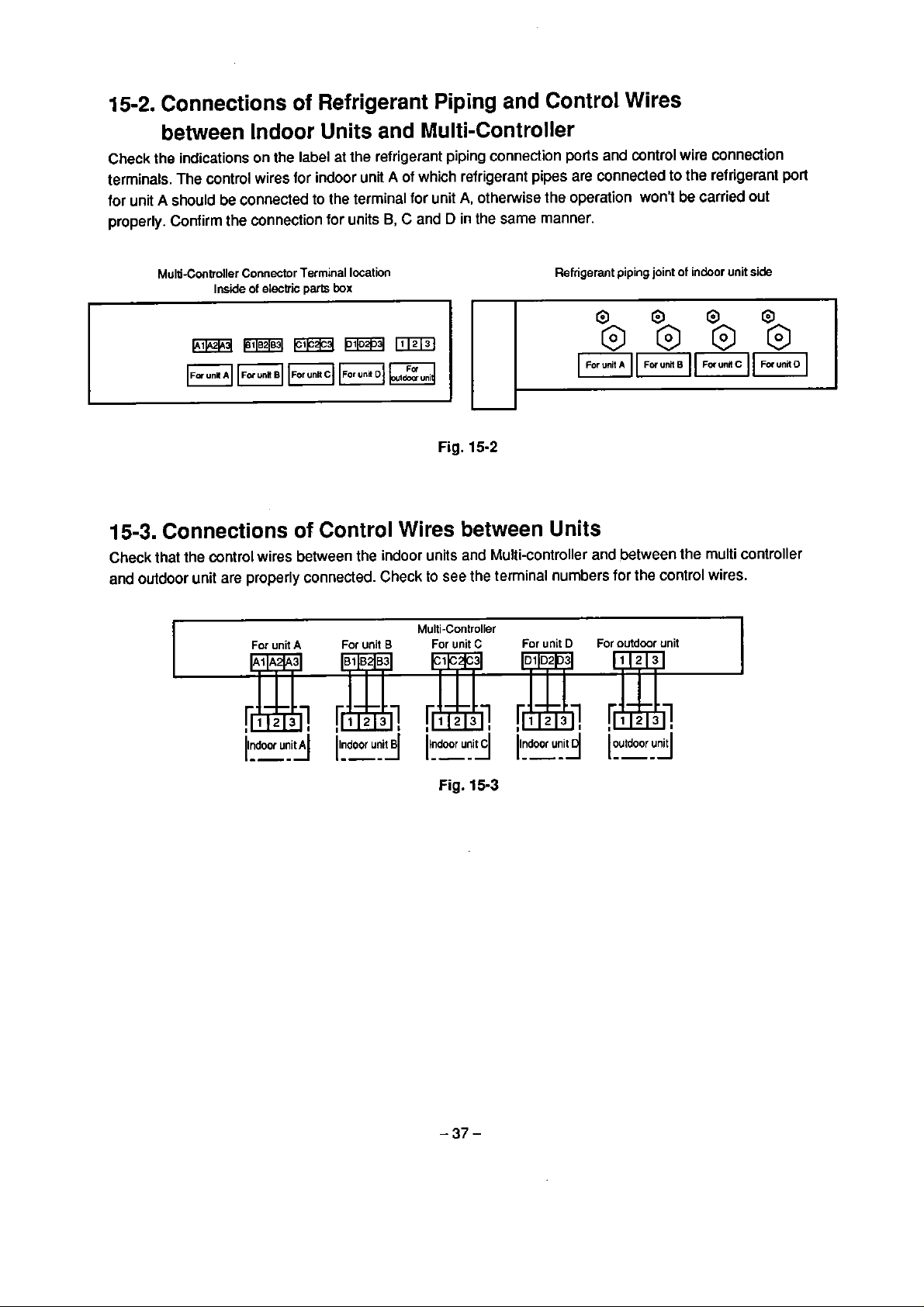
15-2.
Connections
of
Refrigerant Piping and Control Wires
between Indoor Units and Multi-Controller
Check
terrninals. The control wires for indoor unii A of which refrigerant pipes are connected to the refrigerant
for unit A should
properly. Confirm the connection for units
the indications on the label at the refrigerant piping connection
be
connected to the terrninal for unit
B,
C
A,
otherwise the operation won't
and D in the same manner.
ports
and control wire connection
be
carried
out
port
Multi-Controller Connector Termina1 location
15-3.
Check that the control wires between the indoor units and Multi-controller and between the multi controller
and outdoor unit are properly connected. Check
Connections of Control Wires between Units
I
Inside
of
electric
Far
unit
A
partc
box
For unit
to
Multi-Controller
B
Fig.
15-2
see the termina1 numbers for the control wires.
For
unit
C
Refrigerant piping joint
For
unit
D
of indoor
unit
I
side
z
Fig.
15-3
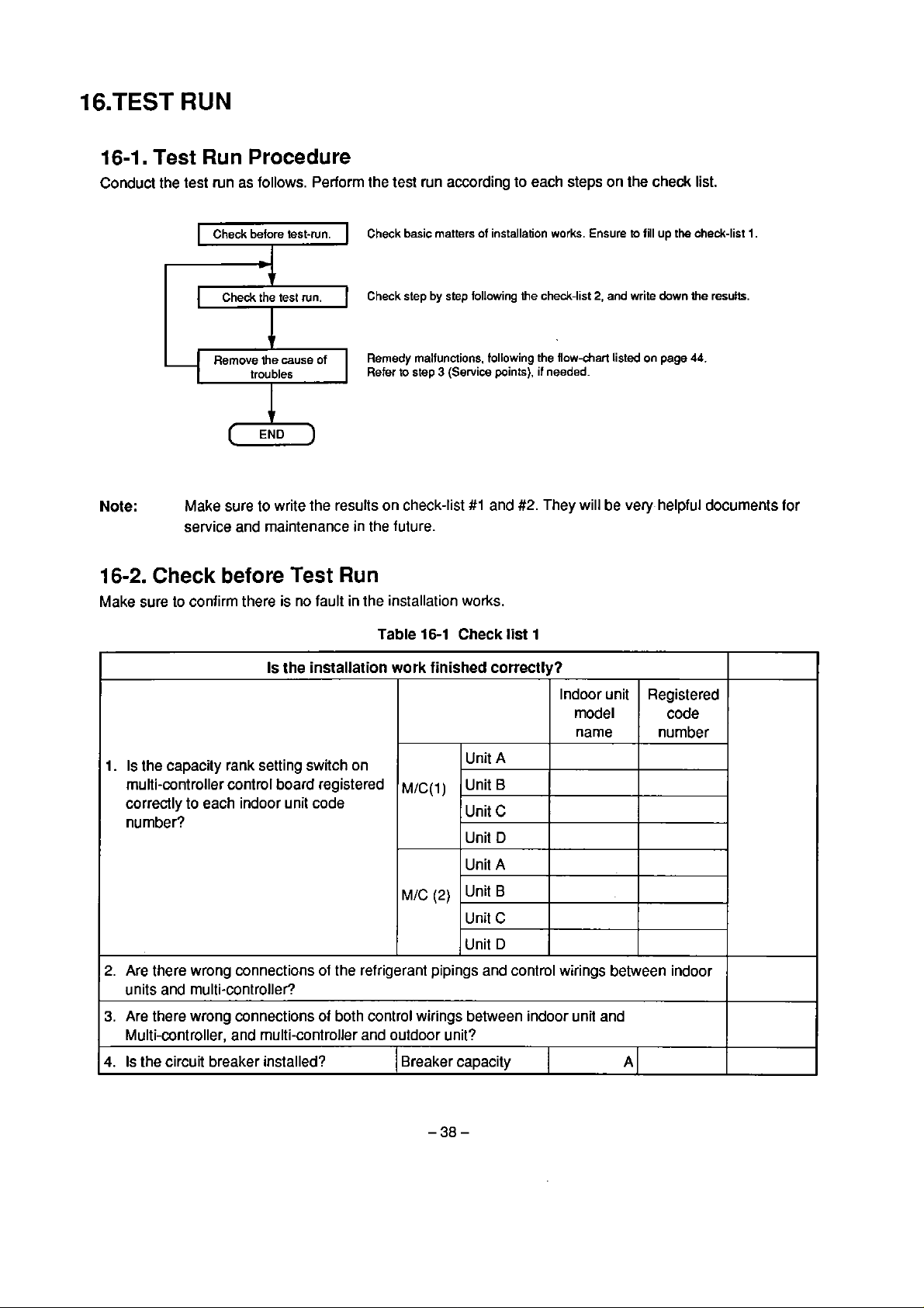
I6.TEST
RUN
16-1.
Conduct the test run as follows. Perform the test run according to
Test Run
Check before test-run.
Procedure
Check basic matters of installation works. Ensure
-
Che&
Remove
trou bles
the test run.
1
lhe
cause of
Check step by
Remedy malfunctions. following the
Refer
to
I
Make
Note:
16-2.
Make sure to confirrn there is no fault in the installation works.
Check
sure to write the results on check-list
service and maintenance in the future.
before
Test
Run
step
follawing
step
3
(Service points), if needed.
#l
and
#2.
each
lhe
che&-list
They will
steps on the
2.
and write
flow-chart
listeci on
be
che&
list.
lo
fill up the check-list
dawn
the
page
44.
very helpful docurnents for
1.
resultr.
Table
16-1
Check
Is
the
installation work finished correctly?
1.
Is
the
capacity rank setting switch on
multi-controller control
correctly
nurnber?
2.
Are there wrong connections of the refrigerant pipings and control wirings between indoor
units and multi-conlroller?
3.
Are there wrong connections
Multi-controller, and multi-controller and outdoor
4.
Is the circuit breaker installed?
to
each indoor unit code
board registered
of
both control wirings between indoor unii and
M/c(~)
M/C
(2)
unil?
Breaker capacity
Unit A
Unit B
C
Unit
Unit
D
Unit
A
Unit
B
Unit
C
Unit
D
list
1
Indoor unit
rnodel
name
Registered
nurnber
A
code

5.
Is the breaker capacity adequate?
6.
Is there any wrong wiring of power
cable?
7.
Is the wire size correct?
8.
Is there a wrong wiring between power source outlet and outdoor unit?
9.
Is the grounding wire attached?
10.
Is there adequate resistance?
(more than
11.
Is the voltage correct?
12.
Does the drainage flow smoothly?
13.
Is the heat insulation sufficient? (Especially connecting parts of indoor unit and
muli-cont roller)
14.
Is there a shorì-circuit of air flow frorn indoor unit?
15.
Is there a shori circuit of blowing air from outdoor unit?
16.
Is the refrigerant added adequately?
17.
Are the valves lully opened?
18.
Is the remote conlroller normal?
10Mn)
Power cable
Control wire
Insulation resistance
Voltage
mm2
rnm2
MQ
V
16-3.
After completion of the check before the test mn, conduct the test run check with the tollowing steps listed in
the check
(1)
(2)
(3)
(4)
(5)
(6)
Test
As for the actual procedure of check list 2 (See page
More than
heater. In the case
or heating operation won't work due to
The test run check, in principle, should be rnade for each and every indoor unit.
operating
piping and
To confirrn cooling and heating operation, operate the unit under the mode within the possible
temperature range to operate the units.
There are few cases when one of two operation modes is norrnal but the other is not. Make sure to write
down the
For this check, you need al least a tester and screw driver
lherrnometer, pressure gauge
Run
Check
Iist
2.
40.1,
and simultaneousty rernove the troubles.
12
hours in advance of the test run, turn on the switch lor supplying power to the crankcase
that the compressor was not warrned up sufticiently by crank case heater, the cooling
protettive
simultaneously, you can not carry on the check for the cross connection between refrigerant
contro1 wiring.
items you have checked.
and
other tools (spanners, pliers, nippers, and pins for reset switch.)
circuit activated.
(+,
-).
If
the multiple units are
We recornrnend you to prepare
a

Operatlon Procedure
1.
Turn on the power.
2.
(Check the Fan operation)
Set the operation mode to
and
start operation.
3.
(Check the Cooling operation)
Set ihe operaiion mode to
"Cooling" and stari operation.
(Once you stopped operation you
have lo wait for 3 minutes to
restart due to the
built in restart
delay circuit functioning.)
"Fan",
Table
16-2
Check list
2
Check Iterns
Is the
LED
on remote controller
blinking?
Are
Ihe conditions initialized for
operation?
Is the air flow discharging from
air-outlet?
1s
there abnormal noise from fan?
Does the compressor start normally?
Is there abnorrnal noise from the
cornpressor or pipes?
Is the cool air flow coming out?
Is the air flow circulaling
adequately?
Conflrmatlon
MIC
(1
)
MIC
(2)
amonamom
rr=crrrr
CCCCECCC
33333333
In this case, check
every indoor unit
operating
simultaneously.
Set the temperature to
the lowest.
4.
(Check for
the
heating operation)
Set the operation mode to
heating
and
start the operation.
(Once You stop~ed operation,
you have to wait for 3 minutes to
restart due to
the
built-in restart
delay circuit functioning.)
1)
(Note
Does Ihe thermostal work norrnally?
(Confirm that compressor stops at
high temperature setting, and
restarts at low temperature setting.)
Is the temperature diff erence correct
between suction air and exhaust air?
Is the voltage of power supply
correct?
(380
-
41
5V
f
10%)
Is the operating current correct?
Is the operating pressure correct?
Does the compressor
stati norrnally?
Is there abnormal sound?
(ComPressor~ PiPings)
Is the warm air flow coming out?
Is the air flow circulating adequately?
Does the thermostat work normally?
(Confirm that cornpressor stops at
low temperature setting, and restarts
at high temperature setting.)
p
/

Operatlon
Procedure
Check
Items
ConfirmatIon
M/C
(1)
UmOPUmOP
=====,C==
ECCEECCC
33333x33
MIC
(2)
In this case, check
every indoor unit
operating
simultaneously.
Se1 the temperature lo
the highest.
1.
When
the
Note:
16-4.
protect the units.
Guidelines
outdoor temperature rises above
16-4-1. Guideline for SuctionlDischarge Temperature
(1)
If
the difference between the dry-bulb temperatures al the suction port and discharge
conditioner is
lhe system is operating properly. (Operation at max.
(2)
11 the difference between the dry-bulb temperatures at Ihe suction
conditioner is
the system
10°C
or more when operation has continued for al least
18°C
or more when operation has continued
is operating norrnally. (Operation at max.
Is the temperature diflerence correct
between suction air and exhaust air?
Is the voltage
correct?
Is the operating currenl correct?
Is the operating pressure mrrect?
of
power supply
(380 - 41
21°C,
Hz)
Hz)
5V
f
1OoA)
it will
for
be
forced into reverse operation to
Diff
erence
30
port
and discharge
at
least
30
minutes in the
minutes in the
port
"COOL"
port
"HEAT"
of the air
mode,
of the
air
mode,
16-4-2. Guideline for
If
the current is within f
syslem is operaling normally. (Cooling: operation at max.
The
current varies as lollows depending on the operating conditions.
(t)
When the current is higher than the standard current
High indoor/outdoor temperatures
Poor heai dissipafion of outdoor
(2)
When the current
Low indoor/outdoor lemperatures
Gas leak (insufficient refrigeranl)
Operating
15%
of lhe value given in the catalog in both the heating and cooling modes, the
is
lower than the standard current
Current
unii
(during cooling)
Hz:
heating: operation at
max.
Hz)

16-4-3. Guideline
(1)
The operating pressure level is generatly as listed below.
for
Operating Pressure
Table
16-3
16
to
20
High pressure:
Low pressure:
Heating
Note:
(2) Changes in high and low pressures caused
Cooling: Operation at max.
The above figures indicate the pressure levels established
temperature
1)
Cooling:
Rise in indoor ternperature:Rise in high and low pressures
Drop in indoor temperature: Drop in high and low pressures
Rise
-
Drop
2) Heating:
Rise in indoor temperature: Rise in high and low pressures
Drop in indoor temperature:
Rise in outdoor air temperature: Rise in high and low pressures
Drop in outdoor air temperature: Drop in high and low pressures
High pressure:
Low pressure: 3 to
"C)
in
outdoor air temperature: Rise in high and low pressures
in outdoor air temperature: Drop in high and low pressures
3.5
15
kg/cm2~
to 5.5 kg/crn2~
to
21
kg/cm2G
4.5
kg/cm2G
Hz,
Heating: Operation at max.
by
changes
Drop
in high and low pressures
Indoor:
Outdoor: 25°C to
Indoor:
Outdoor:
15
rninutes after operation starts up. (dry-bulb
in
operating conditions
Hz
18°C
15°C
5°C
lo
to
to
32OC
35°C
25°C
10°C
16-4-4. Flashing
When the power is turned on, Ihe remote controller's operation lamp will flash (ON for
0.5
sec.). This is not indicative of a failure or rnalfunction.
16-4-5.
In the following cases, "PREHEAT/DEFROST" will flash (at 4 second intervals) on lhe
remote controller. This is not indicative of a failure or malfunction.
Case:
PREHEATtDEFROST
1.
When the cornbination of indoor units exceeds the capacity or when the code number entered
by the capacity rank setting switch
2.
When the indoor unit assigned
selector switch.
of
Remote Controller's Operation Lamp
Flashing
is
incorrect (so that capacity
by
the command has been excluded by the operaling mode
is
exceeded).
0.5
LCD
sec. and
display
OFF
of
the
for
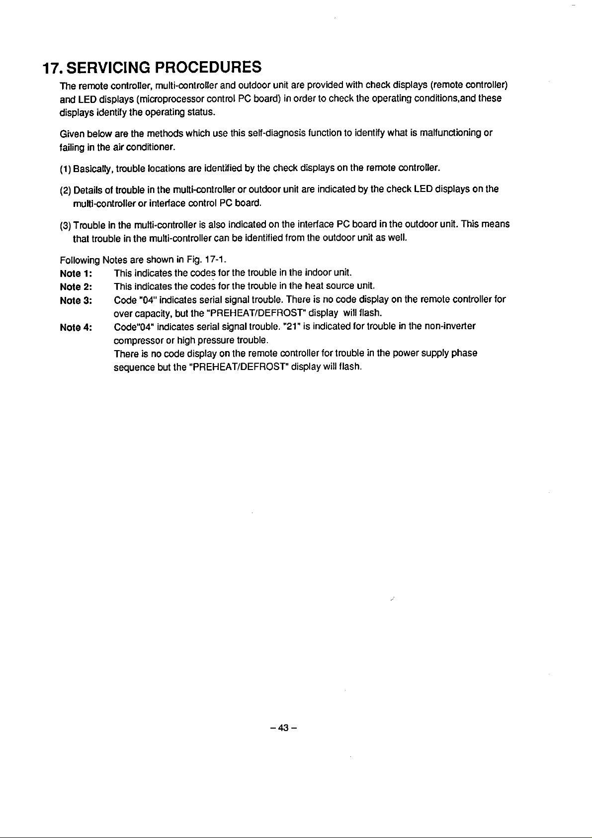
17.
SERVICING
The remote coniroller, multi-controller and outdoor unit are provided with check displays (remote controller)
and
LED
displays ~microprocessor control
displays identify the operating
Given below are the methods which use this self-diagnosis function to identify what is malfunclioning or
failing in the air conditioner.
(l)
Basically, trouble locations are identified by the check displays on the remote controller.
(2)
Details o1 trouble in the muiti-controller or outdoor unit are indicaled by the check
muli-controller or interface control
(3)
Trouble in the multi-controller is
that trouble in the multi-controller can be identified frorn the outdoor unit as well.
PROCEDURES
PC
board) in order to check the operating conditions,and these
status.
PC
board.
also
indicated on the interface
LED
displays on the
PC
board in the outdoor unit. This means
Following Notes are shown in Fig.
Note
Note
Note
Note
1:
2:
3:
4:
This indicates the codes for the trouble in the indoor unit.
This indicates the codes for the trouble in the heat source unit.
Code "04" indicates serial signal trouble. There is no code display on the remote controller for
over capacity, but the
CodeW04" indicates serial signal trouble.
compressor or high pressure trouble.
is no code display on the remote controller for trouble in the power supply phase
There
sequence but the
"PREHEAT/DEFROST"
17-1.
"PREHEATtDEFROST"
"21"
is indicated for trouble in the non-inverter
display will flash.
display will flash.

Remote controller Che& code display
Multi-Controller
(MfC)
Outdoor unit
Interface Control
Inverter Control Board
Multi-Controller
(
M/c)
Board
(IIF)
(INV)
Remote
controller
Indoor
unil
"99.
(Note
1)
(Note
2)
(Note
3)
'15'
1
Remote controller
serial signal abnormality
-
t
Indoor unrt abnorrnality
*TA
sensor abnormality
*TC sensor abnormality 'Od"
=
Water level abnormality "Ob'
Serial
signal abnormality '04'
Outdoor unit abnormality
Power supply circuit abnormality '17" TE sensor abnomality
G-Tr abnorrnality "14"-
Compressor abnormality "ld' abnormality
Breakdown
High pressure SW operation
11
-
"OC'
V")
--)
"1F'
"21"-
MJC
abnormality
Th
(A)
sensor abnormality
Th
(8)
eensor abnormality
Th (C) sensor abnormality '82'
Th
(D)
sensor abnmality
Th
(X)
sensor abnorrnality
-
Water leve1 abnormality
e
Serial signal abnormality
*Outdoor unit capacity
is
not detected
Over capacity
MIC PC board abnormality
Outdoor unit abnormality
ThD1 sensor abnormality
ThD2 sensor abnorrnality
ThS sensor abnormality
T0
sensor abnormality
m
Pischarge temperature
Suction temperature
abnormality
Pressure sensor abnormality
Low pressure
abnormality
Non-inverter wrnpressor
abnormality
High pressure abnonnality
Serial signal abnormality
Power supply
sequence abnormality
gas
phase
leak
(Note
'80'
'81'
'83'
'84'
'Ob'
'04'
'88'
"89'
'8A'
4)
A
-
'AO'
'Al'
'A2'
"A4'
'AS
'A8'
-A
7
"AA'
'AE'
'AD'
'21'
'04'
'AF'
'1
C"
Fig.
17-1
-L
WC abnormality
Displays each
abnormality
Power supply circuit abnonnality
INV abnormality
code
of
IWC
"17
'AB"
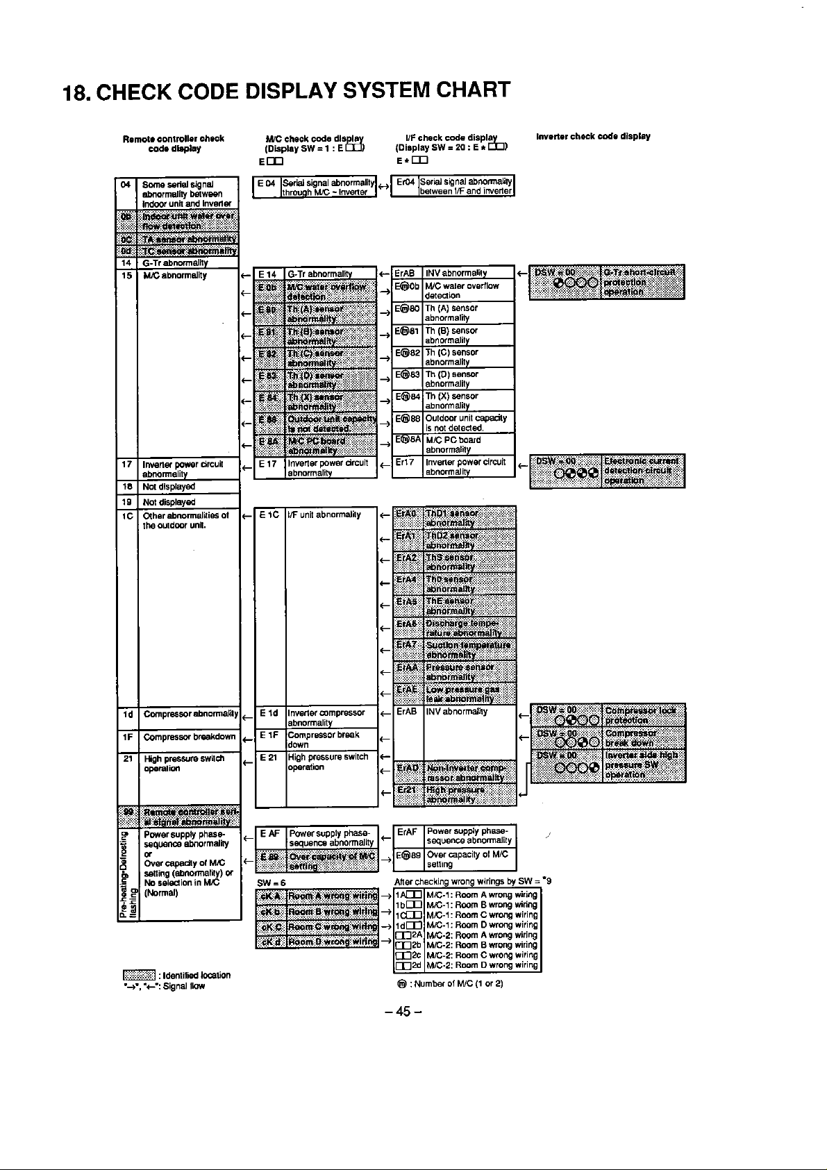
18.
CHECK
CODE
DISPLAY
SYSTEM
CHART
Remote
COdO
controllar
dlapley
chock
W
check code dls I
(Display
Em
SW = 1
I/F check code displa
(Display
SW
=
20 : E
r
:
E
l%
E*m
h)
Inverior check
code
dlsplay

19.
IDENTIFICATION
When there
the check code.
Whether the trouble location
check code.
is
a sign of trouble, do not reset but press the "check switch
PROCEDURES
is in
the
indoor unit, multi-controller or outdoor unit can be identiiied by lhe
on
the remote controller and check
When the failure has been identified to be in
the
LEDs
on
the
contro1
causes of multi-controller failure can also
PC
board incide the electrical parts box of the Multi-controller or outdoor unit.
be
the
multi-controller or outdoor unit, its cause can be
identified from the outdoor unit.
identiiied
The
by

(1)
Press the check switch
(See
pages
49
to
on
the remote controller
56
for the checking rnethod.)
operation lamp lighted?
Is
PREHEATIDEFROST
on the remote controller'c
display?
and
check the check code.
flashing
)YES-
LCD
Trouble in indaor uni1
%C'
Failed
'Od'
Failed
'Obm Incorrect
'04'
Serial signal trouble
'99'
Remote contmlter
serial trouble
Tmuble in outdoor unil
'17'
Defective current circuit
"1
4'
Defective
'l
d"
Defective comprescar
'1
F'
Breakdown
'21'
High-pressure switch
operation
v
Refer to
identification' on page
I
TA
JC
'Check
sensor
sensor
water
Level
G-Tr
codes and
51
lo
56.
the remote controller? not operating.
1C : Trouble in outdoor unit
C
Check the check
I
by the
interface control
the outdoor unit.
function (outdoor unit)'
I
v
LED
display on the
YES
code
PC
indicated
board of
NO
15
C
I
Che& the check code indicated
I
by the LED display on the
control
controller or
control
unit.
Refer
(multi-controller)' on pages
and
function (outdoor unit)' on
pages
Indoor unii fan is
Detective fan motor or
:
Trouble in multi-controller
V
PC
board of the multi-
the
interface
PC
board of the outdoor
lo
'Self-diagnosis function
66
or
to 'Self-diagnosis
57
to
63.
I
64

t
Is the power
supplied between pin 1 and 2 of
indoor unit termina1 plate?
AC
220
YES
-
240V
L
<
Indoor unit abnormality
Indwr unit rniaoprocessor
is
damaged
Remote controller is damaged.
Wrang wiring between indoor
unit and remote controller.
and etc.
Indoor unit trans
Is
switch set correctly?
the power supply wiring correct?
the
.
capacity
is
damaged.
rank setting
NO
z
NO
Is the power supplied
the outdmr unit?
YES
C
Total abnormality
-
Inter-unit wiring connection
damaged.
(Wrong wiring, cut wire,
damaged wntact.)
e
*
Multi-Controller abnormality
Wrong-setting ot the capacity rank setting
switch.(over-capacity sening)
c
Outdoor unit abnormality
Power source phase
(Check code
of
M/C
and
Correct the phase sequence of
to
r
'AF'
is displayed on
iF
PC
board.)
NO
sequence
C
Turn on
>
>
abnormality
the
LEDs
Me
power
Norma1
the
power.
Indoor unit is not selected
by
lhe
Mode Select Switch
Retry to select the
NO
-
r
<
Indoor unit is damaged.
Remote controller is damaged.
Indoor unit abnormality
>

20.JUDGMENT
OF
MALFUNCTIONS WITH
THE
REMOTE
CONTROLLER
20-1.
Check:
Malfunction
Pressing
on
the
the
time
Blinking
INDICATION
Check
check
part
in
The
The
Abnonnal phase of power supply
Display
switch
on,
the
display.
"PREHEAT",
total
capacity of
indoor unit is excepted previously by
Operation
comprescor's
"DEFROST'
the
connected indoor units is too large.
ONIOFF
the
operation mode selector switch.
times
and
the
check
code
are
shown
Blinking
-
At high pressure
"Check"
switch operation
1
Check
switch
Reset
switch
By
pressing the hole with a srnall pin, remote aontroller
(All the rnemories are cleared.)
Displays check
Resets
F
I
Clears check code by
(The start-up nurnber of compressor remains
Fig.
code
by
1
the microprocescor of indoor unit
10
seconds continuous pressing.
20-1
second pressing.
by
power
is reset.
5
seconds continuous pressing.
as
il
is.)

20-2.
By
How
pressing
information
to
Read
CHECK
of 2 faults
key,
tirnes of No.
x
16
units
the
Malfunction
l
are
displayed
unil
compressor-ON
on
the
Check
time
display
Monitor
actuations
area.
Display
as
well
(2
sec.
per one phenomenon).
as
the
check
code
Dispiay h 4
Display
Check
code
Unit
I
MALFUNCTION
dgik
of
In
7
segrnents
information
nu-rnber
CHECK
hexadeejmal
11
che&
L
The
first
I
notatim.
mde
detected
Example
In
~aseof
Example
ki
case
ot
l
ihe
nurnberoflinm
2:
ioom
temperawre
of
cnmprawractwiicns
sensw
of
No.
1
unit
in
lrwbie.
ai
164.
No
display
Ls
made il
L
The
last
detected
there
Is
no
fault.
Example
Far
No.
15
connecting
(serial
signai)
Fig.
20-2
3:
unit,
&le
firctly
are
rown
between
in
buble.
temperaire
lhe
VKkor
se-
and
and
ovMaor
sec;oKly
unib

20-3.
The
Check Code
and
the
Judgment
Table
20-1-A
Check
code
DCI
fl
b
[
Method of
Judgment is performed on the
stop of
outdoor unit. (Operation
continuing)
Judgment is perforrned on the
presente
=
Judgment is performed on the
The resistance value is infinite or
zero. (Operation continuing)
the serial signal from
indoor iinit's board connector
PJ11
by
(IC06).
Float switch rnovement
(Operation continuing)
(Outdoor unit stops fully.)
room temperature sensor.
Judgment
Of
220
-
240V
using the photo coupler
the
Which
Inter-wire for
indoor/outdoor units.
TRS
Crank case heater.
Compressor case
therrnostat.
Drainage systern.
-
Drain pipe
m
Drain
Control
PJl1
m
Photo coupler.
m
Room temperature
senso;
Parts
thermal switch
is
systern.
connector.
(TA).
stuffed.
How
about
the
Conditions
Can't discriminate the signal
a
due to
signal.
.
The serial signal has stopped
because the case thermostat
circuit was opened due to low
temperature in the
cornpressor case.
Float switch movement.
Due to a bad connector
contact, the photo coupler on
the PC board becomes faulty,
and the like.
=
Lead wire cut.
=
Loose connector due to
bad contact.
Wire cut in the sensor.
Short circuit caused
insertion of the lead wire.
Short circuit in the sensor.
stop or wrong
by
a
the
m
m
Od
~udgrnent is performed on the
indoor heat exchanger sensor
(W.
The resistance value is infinite or
zero (Operation oontinuing).
Heat exchanger
sensor
(TC).
Lead wire cut.
-
Bad connector contact due to
loose insertion.
Wire cut in the sensor.
Short circuit due to 1he
insertion of lead wire.
Shori circuit in the sensor.

Table
20-1-A'
How
about the Operation
Although the fan is
carrying on the operation,
cooling or heating
operation does not work
because outdoor
(In norrnal operation, the
LED
for the serial signal
will blink.)
Indoor unit is operating,
bul outdoor unit stops.
Cooling operation carries
on with therrnostat at off
position.
Heating operation carries
on with thermostat at on
position.
una
stops.
Method
Check up lhe inter-wire for wrong
wiring, disconnection, or bad
contact.
Check the current at
thermostat.
In case that termina1 voltage is
applied at the crank case heater
connector, check for crank case
heater.
In lhe case of
at the crank
for cornpressor case
Drainage pipe repair.
Drain pump repair.
Check lhe connector contact
points.
=
Check on the PC board.
Check the resistance value of
sensor.
-
If
there are any peculiar defects,
replace.
of
Diagnosis
TRS
no
terminal voltage
case
heater, check
thermoslat.
TA
Notes
For inverter type, when
aluminum radiation temperature
goes over the
serial signal circuit will be open.
By making the serial signal circuit
of the multi-controller, etc., an
open
circuit, the type that forms a
protective circuit.
There is no
connector.
Due lo the common use of the
board for various models, this
PC
code rnay appear
without drain purnp is connected.
setting value, the
220 - 240V
for
il
the model
PJ11
For cooling operation,
freeze prevention contro1
does not
For heating operation,
outdoor unit carries on its
work interrnittently under
lhe high temperature
release control.
=
For cooling operalion,
freeze prevention control
does not work.
For heating operation,
outdoor unit carries on its
work interrnittently under
the high temperature
release control.
work.
Check the resistance value on
the TC sensor.
If
there are any peculiar defecls,
replace.

Table
20-1-8
Check
code
ICI
7
1
5
i
1
i
d
Method
Judgment is performed on the
over-current protection circuit or
the insufficient voltage
circuit . (Short time)
Fu11 stop.
Judgment is performed on the
temperature sensor
(ThA,
The resistance value is infinite or
zero.
Full slop.
At lhe stop of compressor,
operation judgrnent is
when
the
current sensor circuil.
Full stop.
-
Judgment is performed on the
(LED
50)
inverter
(MCC-1521).
Full stop.
Judgment on the abnormality of
interface board.
,l
stop
Judgment is performed on the
over-current protection
or the insulficient voltage
protection circuit. (Short time)
Full stop.
of Judgrnent
protection
B,
C,
D).
perforrned
current comes into the
red light on the outdoor
contro1 board.
circuil
Which
Power supply.
Wiring.
Fuses.
Giant transistor.
Base drive board.
Smoothing
capacitor.
Rectifier.
Diode.
=
Cornpressor.
Temperature sensor
(ThA,
Assembiy of
PC
14.
Id.
=
21
ThDt,ThD2.
Ths sensor.
Pressure sensor.
Low pressure switch.
Power supply.
Wiring.
Crank case heater.
Comprescor.
6,
board.
items.
Parts
C,
D).
How
about
the Condltlons
Under voltage protection
circuil functioning, due to
voltage reduct ion.
m
Over-current protection
circuit functioning.
Operation stops due to
malfunction
controller.
Due to an abnorrnality
detected in the current,
operation stops.
-
Under voltage protection
circuit functioning, due
voltage reduction.
Over-current protection
circuit functioning.
High pressure switch
functioning.
-
Lead wire cut.
Bad connector contact.
Pressure abnormal.
Loose or cut in sensor
mnnectors.
Discharge air temperature
abnormal.
Under voltage protection
circuit functioning, due lo
voltage reduction.
Over-current protection
circuit functioning.
in
the muiti-
a
a
to

Table
20-1-8'
How
about
the
Operation
Operation stops due to
inverter tripping.
Restart does not work.
Operation stops.
Restart does not work.
Operation stops
Reslart does not work.
Method
Check the power supply.
Repair the disconnection, loose
contact or cut of wires, fbses or
reaclors.
Replace the defective parts.
Check the giant transistor, base
drive, smoothing capacitor,
rectification diode, compressor
and other
connections.
Check the operation of the PC
board.
-
Check the contact condition of
multi-controller temperature
sensor connector and
specif ications.
of
Diagnosis
its
-
Multi-controller type.
Notes
Operation stops.
Restart does not work.
Operalion stops.
Restart does not work.
Check14.
Check Id.
Check
21
items.
Check every sensor resistance.
there are faults of specifications,
repiace.
=
Capiltary tube is stuffed up.
Check
sensor resistance.
m
Check the
=
Repair the disconnection, loose
contacts and cut
power relay.
power
supply
in
wiring
If
and

Table
20-1-C
Check
code
I
F
2
4
q
Method
Judgment is performed when the
larger
one continuously cornes into the
C
urrent sensor circuit.
Full stop.
Judgrnent is performed on the
continuous time for the high
pressure switch functioning.
Wrong wiring between the
remote contro1 and
units, or a selection mistake.
(Stop of operation)
of
Judgment
AC
current than the rated
the
indoor
fan
Parts
motor
Which
Power supply.
Wiring.
Crank case heater.
Compressor.
Operating condition.
Highpressure
switch.
Inner over-load relay.
Indoor
capacitors.
TC, TL sensor
board assembly.
=
Inter-wiring between
remote controller
a nd indoor units.
Unil No. setting.
PC
How
about
the
Conditions
Under voltage protection
circuit functioning,
voltage reduciion.
Over-current protection
circuit functioning.
Malfunctioning
detection circuit.
High pressure switch
functioning
operation.
Can't discriminate the signal
due to a stop or wrong
signal.
by
because of
of
current
overload

How
about
the Operation
Table
Method
20-1-C'
of
Diagnosis
Notes
m
Operation stops.
Restarl does not work.
Operation stops.
m
Restarl does not work.
For wrong wiring,operation
does not start.
m
For wrong setting,
operation starts depending
on the case.
Check power circuit.
Check the causes of abnormal
loading.
Check
Check the causes
loading.
PC
board works.
of
If
there are peculiar
abnormal
defects, replace.
Check
the
TC,
TL
sensor
resistance.
Check PC board works in.
Cut, bad connection of
inter-wiring.
Double setting
No.
l.
of
indoor unil
Both indoor and outdoor unas.
Termina1
A,
B,
C.

20-4.
The
Malfunction
of
the Outdoor
combination
contents below.
of
Judgment
two
display
Unit
selecior
with
switches
the
SeIf-Diagnostic
(SW1,
SW2)
and the
LED
Function
(LD1
-
LD8)
indicate the
Park
lnterface control
location
board
r----
1
Demand
interface board
Multi-Control- Multi-Control- Cornpressor
ler
Fig.
20-3
(l)
control
ler
Electric
7
Inverter con-
7
I
I
Compressor
(2)
parts
location
segmenled
Inverter
LED
I
Oisplay
selector
20-4-1.
Sendinglreceiving
switching
If
the
Set
the
Selector Switch
at
"O"
serial signals
disptay
selector
and
SW2.
Dispiay
seledor
Fig.
20-4
SW1
on Outdoor
operating
l"--
msw4
Push
switch
Interface
status
"-
Display seledor
2
I
SW3
control
are displayed. Following
board
Unit
Interface Board
is
contenls are indicated
by

Display
selector
sw2
Indication
Table
20-2
LD71
7
Segmented
LD72
LED
Display
L073
LD74
Sendinglreceiving status of
O
signal
Operating instruction
from M/C
2
3
.
Outdoor unit operating
condition
4
Operaling instruction
from
6
Inverter operation status
9
M/C
(l)
(2)
serial
Operating
mode
Instruction
frequency
Operating
mode
Operating
mode
Instruction
frequency
Between
M/C (1)
sending
on'y
[SI
Receiving Sending and
only
[Jl
Heating
cooling/heating [HC],
Cooling
Heating frequency
(See table
Heating [H], Cooling [OC],
Simultaneous heating [Hc],
Defrost
cooling
M
/C
operation
[O]
No:
1
unit: [l]
2
unil : [2]
Heating
coolinglheating [HC].
Cooling
Heating frequency [O0 -1
(See table 20-3.)
Abnormal
Between
M/C
No
sendinglrecei
ving
receiving
[H],
Sirnultaneous
[C],
Stop
20-3.)
[Jo],
Simultaneous
[hC]
Frequency
release
No:
Yes:
[H],
Simultaneous
[C],
Stop
Operating
IC1
irequency
[O
IE1
table
[-l
[O0 -1
[O]
[-l
-
(2)
H
[l]
F]
(See
20-4.)
[O]
Fj
F]
Between
Cooling frequency [O0
(See table
Cooling irequency
(See table 20-3.)
Non-inverter
IN"
mrnpressor
Abnormal
Normal
20-3.)
[O0
[O]
-
-1
[E]
lF]
fl
10
1
l
Operating instruction to inverter
Power supply frequency
IC1
Ab"orma'
50Hz
[5]
60Hz [6]
Instruction
irequency
[O
lE1
tabie
[O]
-
F]
(See
20-4,)

Table
20-3
Display
code conversion table
Dlsplay
code
Frequency
conversion
value
(Hz)
Display
code
Frequency
conversion
(Hz)
value
Display
code
Frequency
conversion
value
(Hz)
20-4-2.
If
8et
00
O
10
44.1
01
O
l1
47.2
02
O
12
50.3
03
3.9
13
53.4
Table
05
04
6.9
14
56.5
20-4
Display code conversion table
10.0
15
59.6
06
13.0
16
62.7
07
16.2
17
65.8
08
19.3
18
68.9
09
22.4
19
72.0
OA
25.5
1A
75.1
OB
28.6
1B
78.2
31.7
81.3
I
03456789ABCD
O
30.5
the
Selector Switch
at
"2"
38.1
45.8 42.0
53.4
61.0
68.7
SW1
on Outdoor Unit Interface
76.3
83.9
91.6
Board
OC
1C
103.0
is
OD
34.8
1D
84.4
110.6
87.5
E
OE
37.9
1E
OF
41.0
1F
90.0
F
121.6
Malfunction information is displayed when display selector switch
Table
20-5
7
Dlsplay
selector
20-4-3.
Check code
Outdoor unit
SW
O
The
ErAO
ErAl
ErA2
ErA4
ErA5
2
lndication
Check code
display
Outdoor unit.
MIC
(l),
MIC
(2)
Check Code
ThD1
sensor abnormality
ThD2
sensor abnormality
ThS
sensor abnormality
T0
sensor abnormality
TE sensor abnormalily
Judged
-
LD71
[E]
by
Outdoor
Table
Defects
segmented
LD72
Outdoor unit [rl
M'C
(l) [l1
M'C
(2)
Unit and Multi-Controller
20-6
Judgment
of
sensor, wire cut, short circuit, connectors
SW2
[21
is sei at
"O".
See
LED
dispiay
LD73
Check
For
the contents. see table
the check code.
LD74
20-6.
off

Check
ErA6
code
Judgment
Discharge air temperature abnorrnality (detected by
Refrigerant under-charge, gas leakage, over-loading operating condition
PMV1 rnalfunction (Defect of valve body, defects of coils, connectors off, wire cut.)
=
PMV1 stuffed up
(In cooling, simultaneous cooling operation)
SV13 malfunction
PMV2 malfunction (Defect of valve body, defects of coils, connectors off, wire cut,
PC
board defects)
-
PMV (A - D) in M/C malfunction
SVS (A - D) in M/C malfunction
Defect of expansion valve, expansion valve stuff
(In heating, simultaneous heating operation)
4-way valve rnalfunction
SV14
malfunction (Defect of valve body, defects of coils, connectors off, wire cut,
PC
boards' defects)
SV16 rnalfunction
PMV
(A
-
D) in
M/C
malfunction
Defect of expansion valve, expansion valve stuffed up
ThDI and ThD2 sensor)
ed
up
ErA7
ErAA
ErAE
ErAD
Suction temperature abnorrnality (detected by
Refrigerant under-charge, gas leakage, over-loading operating condition
Pressure sensor abnormality
Defects of pressure sensor, wire cut, connectors off, pressure intake
stuff ed up
Low pressure gas leakage abnormal (Low pressure switch functioning)
Gas leakage, refrigerant
(In cooling, simuitaneous cooling operation)
PMV(A
off, wire cut, PC board defects.)
SVS (A - D) in
Defect of expansion valve, expansion valve stuifed up
(In heating, simultaneous heating operation)
4-way valve malf unction
SV14 malfunction (Defect of valve body, defects of coils, connectors
PC
SV16 malfunction
Cornpressor abnormatity (High pressure switch (63H2), Inner over-load relay
Over-load relay (51C2) in non-inverter compressor side functioning)
(t)
High pressure switch
Over-loading operating condition
(Defects of fan motors and capacitors, wire cut, conneclors off, PC boards' defects)
SV13 malfunction (cooling)
PMV2 malfunction (simultaneous cooling) (Defects ot valve body, defects
connectors
S
PMV (A
-
D)
in
board defects)
Indoor and outdoor fan motors malfunction
off,
V D ( A
-
D ) i n M
-
D)
in M/C malfunction
underchange
M/C
malfunction (Defect of valve body, defects of coils, connectors
M/C
malfunction
(63H2)
malfunction
PC
boards' defects)
/C malfunction (heating, simultaneous heating)
ThS
sensor)
capillary tube
off,
wire cut,
(49C2),
of
coils,
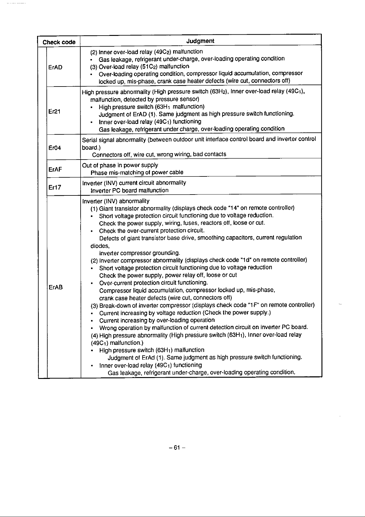
Check
ErAD
code
Judgrnent
(2) Inner over-load relay
(49C2) malfunction
Gas leakage, refrigerant under-charge, over-loading operating condition
(3)
Over-load relay
=
Over-loading operating condition, compressor liquid accurnulation, compressor
(51
C2) malfunction
locked up, rnis-phase, crank case heater defects (wire cut, connectors off)
Er21
Ero4
ErAF
Er17
ErAB
High pressure abnormality (High pressure switch
(63Hz), Inner over-load relay (49Ci),
malfunction, detected by pressure sensor)
=
High pressure switch
Judgrnent of ErAD
(63H
i
rnaifunction)
(1).
Sarne judgment as high pressure switch functioning.
Inner over-load relay (49C1) functioning
Gas leakage, refrigerant under charge, over-loading operating condition
Serial signal abnormality (between outdoor unit interface control board and inverter control
board.)
Connectors off, wire cut. wrong wiring, bad contacts
Out of phase in power supply
Phase mis-matching ol power cable
Inverter (INV)
cuirent circuit abnormality
Inverter PC board malfunction
Inverter (INV) abnorrnality
(1)
Giant transistor abnormality (displays check code
"1
4" on remote controller)
Short voltage protection circuit functioning due to voltage reduction.
Check the power supply, wiring, fuses, reactors off,
loose or cut.
Check the over-current protection circuit.
Defects
of
giant
transistor
base
drive, smoothing capacitors, current regulation
diodes,
inverter cornpressor grounding.
(2) Inverter compressor abnormality (displays check code
"l
d"
on remote controller)
Short voltage protection circuit functioning due lo voltage reduction
Check the power supply, power relay off, loose or cut
Over-current protection circuit functioning.
Compressor liquid accumulation, compressor locked up, mis-phase,
crank case heater defects (wire cut, connectors off)
(3)
Break-down of inverter compressor (displays check code
"1
F"
on remote controller)
Current increasing by voltage reduction (Check the power supply.)
Current increasing by over-loading operation
Wrong operation by malfunction of current detection circuit on inverter
(4)
High pressure abnorrnality (High pressure switch
(63Hi),
Inner over-load relay
PC
board.
(49Ci ) malfunction.)
High pressure switch (63H1) malfunction
Judgment of
ErAd
(1).
Sarne
judgment as high pressure switch functioning.
Inner over-load relay (49Ci) functioning
Gas leakage, refrigerant under-charge, over-loading operating condition.

Check
Multi-cantrokc
code
,E180
E280
Th
(A)
sensor
..
Judgment
abnorrnalily
E181
E28
1
E282
E183
E283
E284
E1
Ob
E20b
E1
88
E288
E1
89
E289
E18A
E28A
Th
(B)
sensor abnorrnality
~h
(C)
sensor abnormality
Th
(D)
sensor abnorrnality
Th
(X)
sensor abnormality
Water level abnormality (Float switch functioning)
Drain heater defects (wire
Float swilch defects (wire cul, connectors off)
Impossible discrimination of outdoor unit capacilies (Displayed when the outdoor unit
capacity was unknown.)
=
Defects of multi-controller control board
-
Defeds of interface board of outdoor unit
Wrong wiring, wire cut or bad connection between multi-controller and outdoor units
Over-capacity
Displayed when lotal capacity of each indoor unit exceeds
capacity
M/C
board abnormality
Displayed when the multi-controller contro1 board does not work normally.
Defects of SenSOiS, wire Cut, shon drcuit, mnnedors off
cui, connectors off)
1.35
tirnes of outdoor un2

20-44. If the Setector Switch
SW1
on
Outdoor Unit Interface Board
is
Set
at
"3"
Capacity rank setting is displayed. Following contents are indicateci by switching
Table
20-7
7
Display
Selector
sw2
O
1
3
4
5
8
Indication
Outdoor unit horse power
Room A
Capacity
-
indoor unil
connected to
MiC
Capacity rank
indoorunit
connected lo
M/C
(l)
(2)
rank
of
of
~oom
Room C
Room
RoornA
Room
Roorn
Roorn
B
D
i3
C
D
LD71
[91
[A]
[b]
[CI
[d]
[Al
[b]
[C]
[d]
Segmented
LD72
8 HP [8],
Displays the code number of indoor unit
regislered
Code
No.
4
O
2
3
5
to
M/C
Capacity
rank
No
connection
-
130
160,200
260
LED Display
10
HP
[A]
Code
No.
6
7
8
9
10
the
display selecior
Capacity
rank
-
-
380
-
460
LD73
[H]
SW2.
LD74
[P]
20-4-5.
Sensor data is displayed. By switching the
Display
Selector
SW2
O
1
2
3
4
5
If
the Selector Switch
Indication
Pressure sensor data
ThD1
sensordata
ThD2
sensor data
ThS
sensor data
TE
sensor data
T0 sensor
data
SW1
on Outdoor Unit Interface Board is Set at "4"
SW2,
the contents are shown in table 20-8.
Table
20-8
7
Segmented
LED
Display
LD71
[p]
Idl
[dl
[SI
[h1
[h]
LD72
[dl
['l
[21
11
1
['l
[o]
LD73
Data
100
-
FO]
See the conversion table
(Table
on pages
20-1 4,20-15
59.
and
LD74
20-1
6)

20-4-6.
PMV
sw2.
Display
Selector
If
the Selector Switch
opening inforrnation is displayed. Following contents
Indication
SW1
on
SW2
PMV1
PMV2
opening
opening
2
3
Outdoor Unif Interface Soard
are
indicateci by switching the display selector
Tabie
20-9
7
LD71
[p]
[p]
Segrnented
LD72
[l
1
[*l
LED
Display
LD73
Data
[O0 - FO]
See the conversion table
(Table
20-1 2)
68.
Cornpleteiy ciose
Fully open [FO]
is
Set
on pages
at
"I"
LD74
1001
67
and
-
20-5.
The
contents below.
Malfunction Judgment with the Self-Diagnostic Function
of
the Multi-Controller
combination of the display switches
Display
(SW)
Fig.
and
four
20-5
Contro1 board
segments
7
segrnented
Display
LED
LED
selector
(LDIO1
switches
-
LD104)
indicate
the
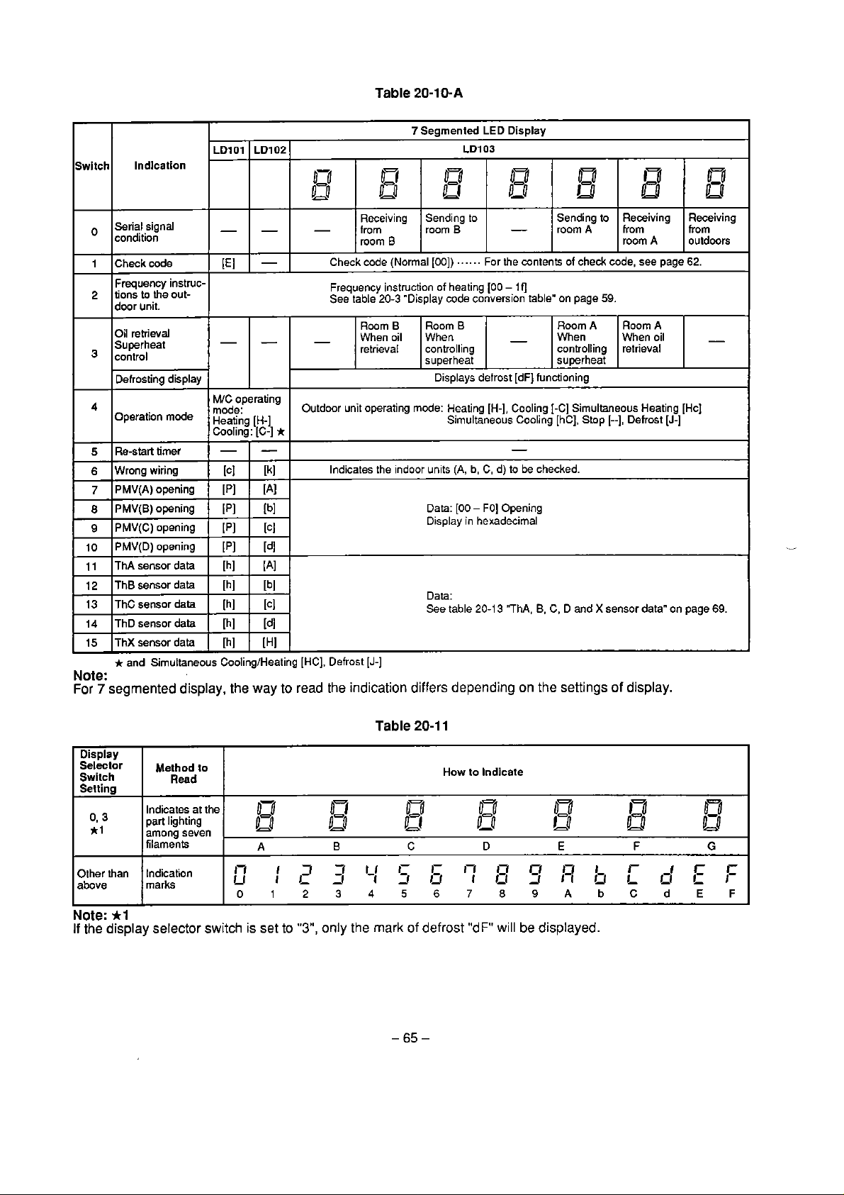
Switch Indlcation
Serial signal
O
condition
Frequency instruc-
2
tions
to
I
I
P-
3
5
6
Iwrong wiring
the out-
I
door
unit.
--.
-
~
Oil
retriwal
Superheat
contro1
1
Dehostina displav
Operation mode Heating [H-]
I
IRe-start
timer
-
I
-
-
-
1
I
M/C operating
Cooling: [C-]
Imode:
)
-
I
-
I
[C]
I
[k]
*
Table
20-10-A
7
Seamented LED Dis~lav
0
B
Sending to
3
room
. . .
Room
B
When
controlling
su~erheat
I' I
Displays defrost
Simultaneous Cooling [hC], Stop [--l, Defrost [J-]
-
. .
.
For the contents of che& code, see page 62.
-
Ilj
-
[dFj
-
-
Outdoor
Receiving
from
room
C
heck code (Normal [00])
Frequency instruction of heating 100
See table 20-3 "Display code conversion table' on page
Room
When oil
retrieval
1
unit
operating mode: Heating [H-]. Cooling
-
Indicates the indoor units
(A,
b,
C,
d) to be checked.
Sending
ta
room A
RoomA
When
controlling
sutterheat
1.
functioning
[-C]
Simultaneous Heating [Hc]
Receiving
from
room A
59.
Room
When oil
retrieval
A
Receiving
from
outdoors
-
I
11
IT~A
sensor data I [h] I (A]
12
IT~B
sensor data I [h] I [bl
13
IT~C
sensor
data
I
ThD sensor
14
ThX
15
*
and Simuttaneous CoolingIHeating [HC], Defrost
data
sensor data
Note:
For
7
segmented
Display
Selector
Swilch
Setting
irl
Other than
above
Note:
*l
If
the
display selector switch is set to
display, the
Method lo
Read
Indicates
part lighting
among seven
filaments
Indication
marks
at
the
Data: [O0 - FO] Opening
Display in hexadecirnal
[h] [ [C]
[h]
[d]
[h]
[H]
[J-]
way
to read the indication differs depending
Table
r,
"3",
W
D-1
Lo
B
,rii
,i
only the
7
mark
ltfl
U
A
17
I_r
l7
i
0123456789AbCdEF
Data:
See table 20-1 3 'ThA,
20-1
1
How to Indicate
B.
C, D and X sensor data" on page
on
the settings
of
display.
-
13
U
C
-
-
bb"Ey2b
of defrost
1-fl
?A'
D
I
"dF"
will
h3
L4
E
be
displayed.
I
I
L4
L!!
F
~bcr
P
T
69.
Lo
P,P
G
T
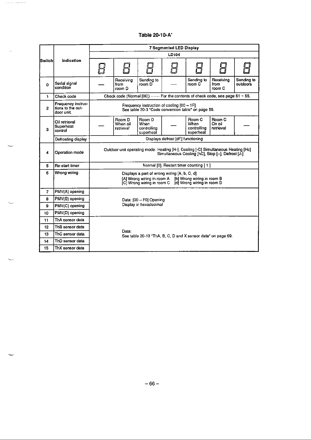
Switch
Serial signal
cond~tion
1
Checkcode
Frequency instruc-
tions to the out
2
door unit.
Oil retrieval
Superheat
3
contro1
Defrosting display
Indication
W
o2
!LO
-
Check code (Norma1 [DO])
-
kr
U
Receiving
from
room
D
Frequency instruction of cooling [OD
See table
Room
D
When oil
retrieval
Table
20-1
0-A'
7
Segmented
07
.
El
Sending to
D
room
.
. .
. . .
20-3
'Code conversion table' on page
'Room
O
When
controlling
superheat
Displays defrost [dF] functioning
LED
Display
LD104
03
'DO
For the contents of check code. see page
-
03
iu
Sending
room
C
-
1
F]
Room
C
When
controlling
superheat
to
59.
Receiving
from
room C
Room
C
On
oil
retrieval
Sending
outdoors
51
-
55.
to
Operation mode
4
Re-star1 timer
5
Wrong wiring
6
PMV(A) opening
7
PMV(B) opening
8
PMV(C)
9
PMV(D)
i0
ThA
11
Th8 sensor data
12
ThC
13
ThD
14
15
ThX sensor
opening
opening
sensor
data
sensor
data
sensor data
data
Outdoor unit operating mode: Heating
Displays a part of wrong wiring
[A] Wrong wiring in room A
[C] Wrong wiring in room
Data: 100 - FO] Opening
Display in hexadecimal
Data:
See table
20-13
Simultaneous Cooling IhC], Stop
Normal IO], Restart timer counting
C
"ThA,
B.
C. D and X sensor data" on page
[H-],
Cooling [-C] Simultaneous Heating [Hc]
[A.
b,
C, d]
[bl Wrong wiring
[d]
Wrong wiring in roorn
I
in
1
1
room
[--l,
B
D
Defrost
69.
[J-I

20-6.
PMV
Opening
Degree, Temperature Sensor
and
Pressure
Sensor
20-6-1.
Data
PMV
PMV
PMV1,
PMV
00
(0)
FO
(240)
Code
Display
Conversion
Table
(Electronic Flow Control Valve) Opening Degree
(A),
(B),
(C),
(D)
.....................................
2
................................................................
opening
degree
................
................................
.......................................................................
.................
..................
........................
Table
,
,,..,..
Multi-mntroller
Oudoo unit
O
lo
Fully
........
Fully open
20-1
2
Display
34
35
36
37
38 56
39
3A
38
240
pulses
closed
Opening
deg
(pulsel
ree
52
53
54
55
57
58
59
Data
3
C
3D
3E
3F
40
60
61
62
63
64

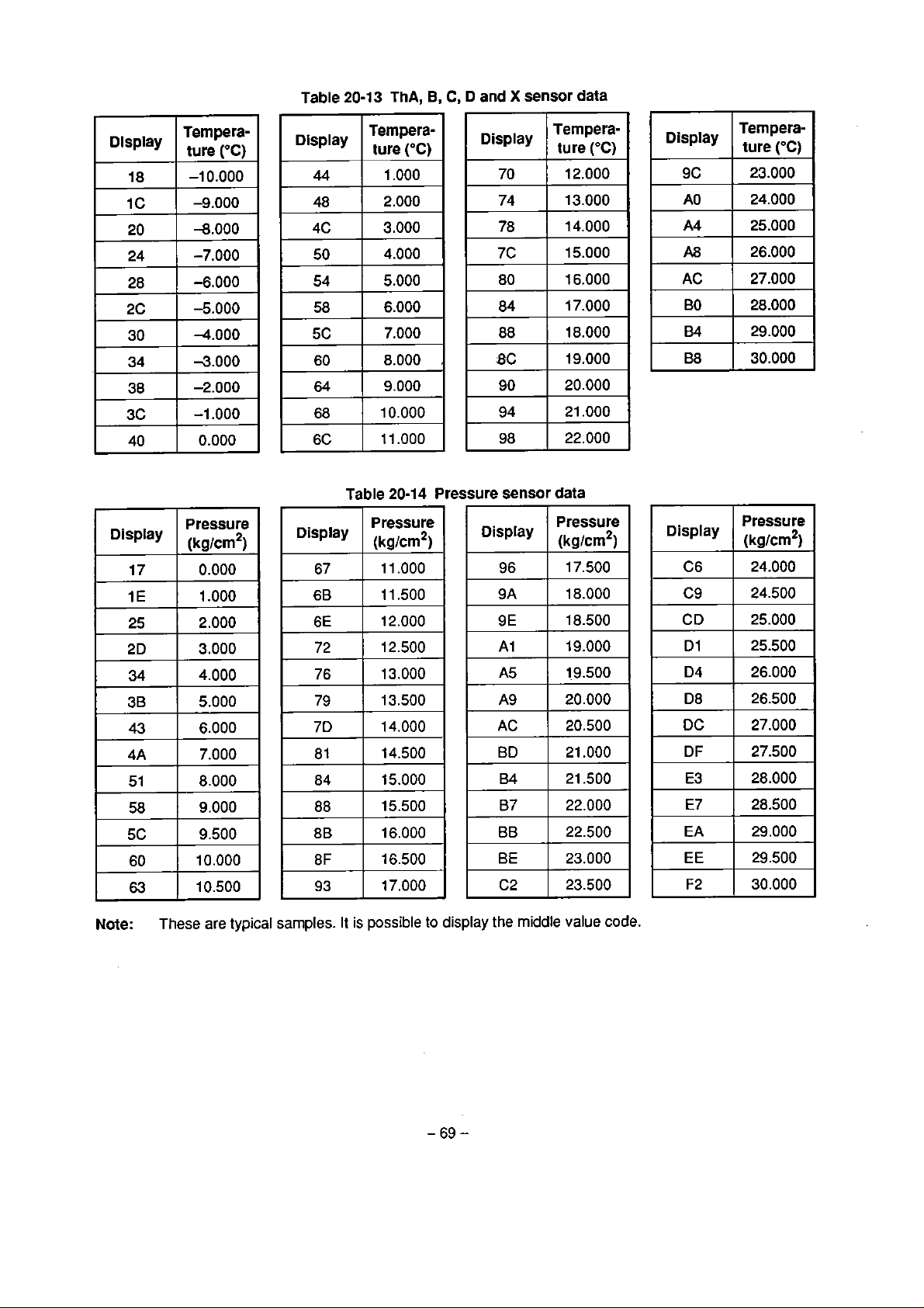
Table
20-13
Table
ThA,
20-1
B,
C,
4
Pressure
D
and X sensor
sensor
data
data
Note:
These
are
typical
samples. It
is
possible
to
display
the
middle
value code.
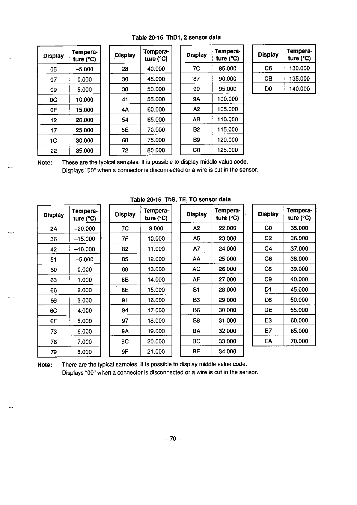
Table
20-15 ThD1,2
sensor
data
Tempera-
ture
(OC)
130.000
135.000
140.000
Note:
These afe the typical sarnples. It is possible to display middle value code.
Displays
"00"
when a connector
Table
is
disconnected
20-16
ThC.
TE.
or
T0
a
wire
sensor
is
cut
in
data
the sensor.
Tempera-
Note:
There are the typical samples. It is possible lo display middle value code.
Displays
"00"
when a connector is disconnected or a wire is cut
in
Ihe sensor.

21-1.
Microprocessor
the
Remote controller
I
I
I
I
I
I
I
l
l
I
A
few
Malfunction
Indoor unit
l
I
l
1
I
I
I
I
I
I
I
sec.
I
I
System
-
-
1
min
Diagram
Multicontroller
Multicontroller
(M/C
2)
I I I
I I I
I I
l
l
l
I I
I I
I I
l
I I
I I
I
I I
I
I I
I I
I
I
l
I
I
Fig.
21-1
and the
--
1
min.
Time Required
-
Interface Inverter
microprocessor microprocessor
to
IIF
I
I
I
I I
I I
I I
I I
I
I
I
I
I
I
I
l
i
l
min.
I
I
I
1
I
I
I
I
I
I
I
I
I
I
I
I
I
I
I
I
I
I
I
Judge
The
tirne
to
display the indication on the remote controller.
Seria1 signal abnormalities:
(1)
Between the
a
(2)
M/C
a
(3)
Indoor
a
(4)
The
few seconds + one minute + one minute + one minute
and
few
few seconds + one minute
remote
IIF
and the INV
the
I/F
seconds + one minute + one minute
unit
and the
MIC
contro1 and indoor units
a few seconds
INV
abnormalities:
a little more than three minutes
IIF
abnormalities:
a
little more than two minutes
M/C
and indoor
unit
microprocessor abnormalities:
a little more than one rninutes
=
more
=
than
one minute
=
more than three minutes
more than two minutes

21-2.
A
Check
of
the
Control
Multi-Controller Control Board
There are
Measure lhe voltage between the
When there is no voltage, take off
voltage. When approximately
transformer defects.
two
types of contro1 circuit power voltages,
5V:
............................................................................
12V:
..........................................................................
18
Circuit Power Voltage of the
5V
and
GND
and the checkpoints shown in Fig.
PJ16
(in condition without loading), measure the transformer
-
20V
AC
(at
240V)
is detected, the relay
12V.
(Cornrnon
Electronic circuit power
Relay drive circuit, power
GND).
21-2.
board
is
defective, otherwise,
for
the
PMV
secondai-y

21-3.
A
Check
of
the Control
Interface Board
There
are
two
types
of
contro1 circuit power voltages,
5V:
............................................................................
12V:
........................................................................
Measure the voltage between the
When there is no voltage, take off
voltage. When approximately
transformer defects.
18
Circuit
GND
and the checkpoints shown in Fig.
PJ8
(in condition without ioading), rneasure the transformer secondary
-
20V
AC
(at
240V)
Power
5V
and
is detected, the relay board is defective, othetwise,
Voltage
12V.
(Common
Electronic circuit power
e
drive circuit, power for the
of
the Outdoor
GND).
21-3.
PMV
Fig.
-
73
21-3
-

-4.220 - 240V
Multi-Controller
r'-'----------------------------------------
System
Diagram
l
I
I
l
X
-
a
%
B
B
a
-
C
ò
v
C
Fig.
21-4
Multi-controller
-74-

Power
3
phase
supply
380-415v
50Hz
A/C
220-240V
A/C
220-240V
TRIAC
72
Fig.
21-5
-75-
Outdoor
unit

22.REMOTE
CONTROLLER DISCRIMINATION FUNCTION,
OUTDOOR UNIT DISCRIMINATION FUNCTION
For each of one outdoor
To search for connected outdoor unit
T
o
search for connected remote controllers from the outdoor unit.
unit
system, it
is
possible;
from
the remote controtler.
22-1.
22-2.
Search
I
Remove
l
I
Select
timer.
I
(Short circuit
The
unit, striking
seconds, opens
5
minutesl.
Stop
Search
Set the display select rotary switch No.
on the interface board in outdoor unit to
"3".
"5"
or
l
Press the push switch
for more than
"7".
from
Turn on the power.
the
(or tum over the remote oontroller)
"Fa".
2
way
valve for
with
shorting
(Remove
from
Turn on the power.
two
seconds.
the
remote controller cover
mode. and shoit cicuit the
the
timer by a short pin.)
the
bypass of outdoor
a
grinding noise every
and
closes repeatedly (for
the
remote contro1 timer.
the
timer short pin.)
Outdoor
SW3
ori lhe board
Remote
2
Unit
I
1
*2
I
Controller
I
1
Procedures
I
I
I
*lI
I
1
Check
the connecled
outdoor unit.
l
1
Procedures
I
t1
:
Figure
olcover
oli.
~Shorl~
Fix
shori-pin wilh
*2
Depending
judgemenl on the remote cwitrol
the followhg division.
Parts location
on
ihe selting oi
In
the case o1
In Vie
In the case of '7': Multi-controller MIC
(The
'3':
of
'5':
All systems
Multi-controller
case
lay-oul diagrarn on
/
an
acihesive
3'.
'5
and
'T,
can
be
M/C
(1)
(2)
the
interface
7
segrnented LED
lape
the
done in
system
system
board)
,
Dispiay
The remote controller's "PREHEATING"
"DEFROSTING"
blinking.
Set the display select
1
Na
l
b
indication will
"O".
starl
rolary switch
,
I
I
Check
the connected
remote
I
controllers
I
End
Push switch
SW3

23.CHECK
CONNECTION
The
units have a function
multi-controller and
the cases
Cases:
listed below.
1.
The capacity of indoor units setto
multi-controller contro1 board.)
2.
Remote
3.
Out of phase.
FOR REFRIGERANT PIPING AND INTER-UNIT WIRING
to
check
the
wrong connection
indoor units. Conduct the check at the test
''O".
controller of indoor unit dici not set to "cooling" (Select "cooling")
in
inter-unit wiring, or wrong connection (Connect the wire to correct termina1
of
refrigerant piping and inter-unit wiring between
run
as
follows. This function does not work in
(Select the correct capacity with the switches on the
23-1.
Check
System
Turn
Procedures
the
C
Open the electrical parts
3
Frequency
setting
Set up the operaiion Irequencies.
Depending on the
I
ternperatures. sei the rotary switch (display
switch) on the intedace (IIF) board in the
outdoor unir to either
room and arnbient
il
4
Set
up
the
operation
5
Start the
check
6
End
of
check
7
Judgernent I Check. a wrona wirina or not. In the case
8
Reset
Note: When there
turning off ihe power and perform a check again.
units wnnected to the outdoor unit to
cooling operation, and press
button. (No need for temperature setting)
Press the push
(Mcre than iwo seconds)
(Eighr
unii will simultaneously start to btink.)
(SFrt to check with indoor unit A and carry
on in iurn. Durino che check. al1 of the
'rndoortiniG 'semire controll~rs display
"PREHMT'.
indoor unit fan keeps to stop operation.)
SW
LED5
on the I/F board in outdoor
"DEFROST
f
thc
Atrer cornpletion of the operation larnp on
ihe remote wniroller gws off. As br ihe
outdoor unit,
operation and
on the
of wrong wirinc 7 segrnented
indicare the defective indoor unit. You can
also use 7 segmented
controller for this check.
minutes for the check. But il varies depend.
ing on room and arnbient air ternperature.
l
I
When ihe check is cornpleted, rnake sure
io return ihe rotaq
.,n,,
U.
(Il it is not returned io
nection check will finish as it
be
ooeraton.l
afe
rhe compressor sfops the
the seven segrnented LEDs
VF
board also stop blinkina.
t
SW
poscible io do rile cooling or the healing
some wrong connecrions, repair ihem after
power on.
box
"9"
or
'10'.
ttie operation
No.3 on the IiF board
blinking, and lhe
LEDs
LEDs
on
the
takes max.
the wrong
S.
and il won'i
rnulti-
10
con-
li
on the IiF board to
"O",
1
I
I
I
(The lay-oul diagram lorthe switch on the inledace board)
(Standard lor the check operation trequency se1ection.J
Y
21
5
(7
segmented LED indication on the
(Examp4e) If there is no wrong oonnection in
system,
When there are wrong
f'
and
seconds.
(The
the multi-motniiier
(Exarnple) When there are wrong conneciions
in unii C and
displayed every iwo secunds.
If
ihere are wrang conneaiofls in al1 of the unii
C
and
.
7.T
is displayed.
"&
will
be
two
digit, 7 segmented
7segmenied
+7
D.
'T'
D,
al1 Ihe syrnbols
L-.-
mnneaions in unii C and
aliernately displayed every
ima.1
LED
and
"'d
are
I
LED
WhenLe prebsus
IO
bw
~srpsiiunta
ii==arr
iteemipsrrr
by
pmeaivc
ard
BuiLEDn
tdnhkqngatir.
UF
display on
iidmrnd
ga.
d-ihirdmiq,
[hs
Eh&
wiUmmtlo
YFboidanlnia
baard.)
L-
D~wiOlqr
!h
M/C
IWO
ldl
orMm
dr-harge
mi
vll
~wm
bs
.
uni
*h
(l)
D,
+
wili
ba
alternaieiy
A,
dispiayed evey huo seconds.
8,
&m
mpped
h
d
d
ihì.
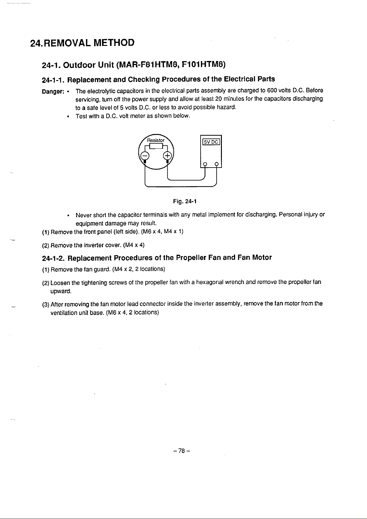
24.REMOVAL
METHOD
24-1.
24-1-1.
Danger:
(1)
Outdoor
Unit (MAR-F81
Replacement and Checking Procedures
The electrolytic capacitors in the electrical parts assembly are charged to
servicing, turn off the power supply and allow at least
a
safe level of 5 volts
to
Test with a D.C.
Never short the capacitor terminals with
equipment damage may result.
Remove the front panel (left side).
HTM8,
D.C.
or less to avoid possible hazard.
volt meter as shown below.
(M6
x
4,
M4 x 1)
Fig.
F1
24-1
any
O1
HTM8)
of
the
Electrical
20
minutes for the capacitors discharging
rnetal implement for djscharging. Persona1 injury
Parts
600
volts
D.C.
Before
or
(2)
Remove the inverler cover.
24-1-2.
(1)
(2)
(3)
Replacement Procedures
Remove the fan guard.
Loosen the tightening screws of the propeller
upward.
After removing the fan motor lead connector inside the inverler assembly, remove the fan motor frorn
ventilation uni1 base.
(M4 x 2,
(M6
x
(M4 x 4)
2
4.
2
locations)
of
the
locations)
Propeller
fan
with a hexagonal wrench and remove the propeller fan
Fan
and Fan Motor
the

24-1-3.
(l)
(2)
(3)
(4)
(5)
Replacement Procedures
Remove the front panels (left and right sides).
Purge the refrigerant.
Remove the inverter cooling duct.
Remove the strut (front). (M6
Remove the upper cover
of
(M6
x
9,
M4
x
the inverter unit.
of
the
compressor unit
(M6 x 4,
x
2)
1)
cover
-
2
locations, M4 x
1)
Fig.
24-2
(6)
Remove the fixing screws of
the
inverter assembly.
(M4
(7) Remove al1 the connectors of 2-way valve coi1 lead and
(8)
Remove the inverter assembly to the front.
(9)
Rernove the noise reduction box
(10)
Remove
the noise reduction box
(A).
(6).
(M4 x 7)
(M4
x
4)
\
\
Noise
reduction
box
(A)
x
etc.
Crank
2)
inside the inverler assembly.
Noise
reduction
case
heater
box
18)
Fig.
24-3

(1
l) Remove the noise reduction materia1 and crank case heater.
(12)Remove the discharge temperature sensors
(2
locations on left and righl side) mounting on the discharge
pipe and remove the discharge pipe from the compressor.
(13)Remove the suclion temperature sensor
(2
pipe from the cornpressor.
(14) Remove the equalizer pipe
localions)
on
the suction pipe.
(1
location) mounting on the suction pipe and remove the suction
Fig.
(1
5)
Loosen the cornpressor fixing nuts (M1
0 x 3)
and remove them. (M1
24-4
\
Remove
(Discharge
at
0 x 3)
2
locations.
pipe)
.-
(l
6)
Rernove
(1
7)
lnseil a rectangular lumber or etc. (as carrying guides.) under the bottom of the compressor leaning the
the
connection lead wires on the compressor and termina1 sections.
compressor.
(1
8)
Move forward Ihe compressor rolling lefl and right
(19)
Replace the compressor.
by
using
the
hooks for hanging.
(20)After replacing the compressor, perform the procedures in reverse order of removal.
Hook
for
I
hanging
Fig.
24-5
\
Lumkr
24-1-4.
(1)
(2)
(3)
(4)
(5)
(6)
Replacement Procedures
Rernove the front panel (lefl and right side). (M6
Purge the refrigerant.
Remove lhe inverter assembly fotward according to the procedures described in
Remove
Remove the accurnulator fixing screw. (M6 x 1)
Replace the accumulator.
the
pipes connected to the accumulator.
of
the Accumulator
x
4,
2
locations, M4 x 1)
itern
24-1
-3.
24-1-5. Replacement Procedures
(1) Rernove the front panel (left and righl side). (M6 x
(2)
Purge the refrigerant.
(3)
Remove the pipe connecled to the liquid tank.
(4)
Rernove
(5)
Replace the liquid tank.
the
liquid tank fixing screws. (M6
24-1-6. Replwement Procedures
(1) Rernove the front panel (left
(2)
Purge the refrigerant
(3)
Pull the replacing~ouldoor unit out frorn the coupled outdoor units.
(4)
Remove the fronl panel (right), the exhaust
ventilation assertibly.
the
(5)
Replace the heat exchangers (upper right, lower right, upper left, lower lefl). (M4
and
of
the Liquid
x
2)
of
the Heat Exchanger
right side). (M6 x
air
cabinet, the side plate (right and lefi), the strut (back), and
4,
2
4,
M4 x 1)
Tank
locations,
M4
x
l)
x
8,
2
locations)

Discharge
air
cabinet
+
Propeller
fan
v
"
Fig.
24-6
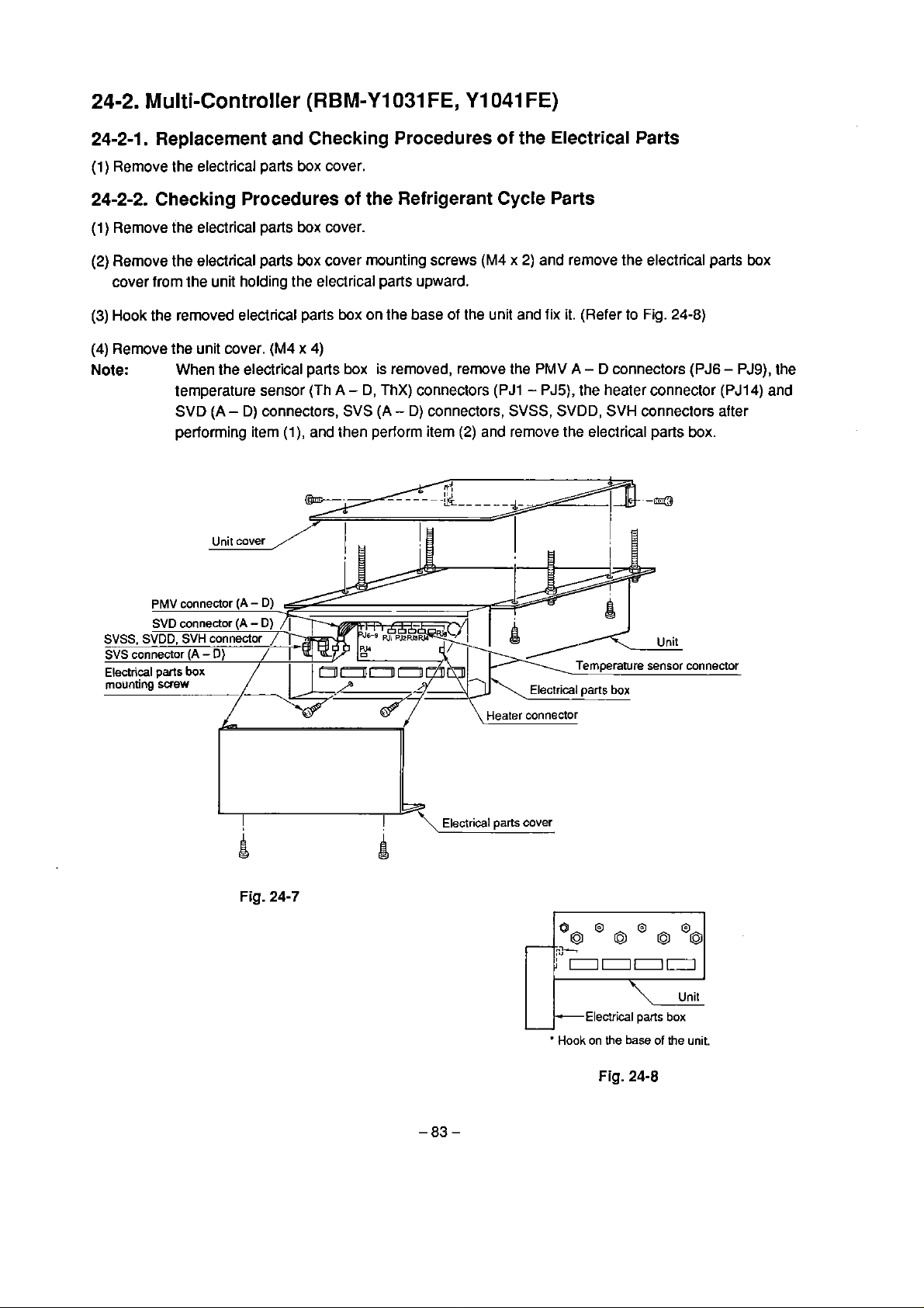
24-2.
Multi-Controller
(RBM-Y1031
FE,
Y1041
FE)
24-2-1. Replacement
(1)
Rernove the electrical parts box cover.
24-2-2. Checking Procedures
(1)
Remove the electrical parts box cover.
(2)
Remove the electrical
cover frorn the unit holding the electrical parts upward.
(3)
Hook the removed electrical
(4)
Remove the unit cover.
Note:
When the electrical parts box is rernoved, remove the
temperature sensor (Th
SVD
(A
performing itern
and
parts
box cover mounting screws
parts
(M4
x
-
D) connectors,
(l),
Checking Procedures
of
the
Refrigerant Cycle
box on the base
4)
A
-
D,
ThX) connectors
SVS
(A
-
D) connectors,
and then perform itern
of
the
Electrical
Parts
Parts
(M4 x 2)
of
Ihe unit and fix it. (Refer to Fig.
(2)
and remove the electrical parts box.
and rernove the electrical parts box
PMV
A
-
D
connectors
(PJ1 - PJ5),
SVSS,
the heater connector
SVDD,
SVH
connectors after
24-8)
(PJ6 - PJ9),
(PJ14)
the
and
A
Fig.
24-7
r
Electrical
parts
cover
k~lectrical
Hook
on
the
Fig.
pms
base
24-8
of
box
the
unit.

24-2-3.
(1)
(2)
(3)
Note:
Replacement Procedures
of
the Refrigerant Cycle Parts
Purge the refrigerant frorn the outdoor unit.
Rernove the refrigerant pipes and the inter-unit wiring connections.
Bring down the mulli-controller frorn the ceiling.
1.
Replacernent of the refrigerant cycle parts should be perlormed with the multi-controller broughi
down from the ceiling.
2.
Replacernent of
PMV,
the expansion valve, the check valve, the magnetic valve should
periomied while cooling the valve main body by wet clothes.
3.
For locations of the parts, please see the
parts
Heat
lists.
insulatar for
pipes - foamed
polyethylene
(with heat-proof adhesive)
be
Heat
insulalor
Fig.
-84-
24-9

24-2-4. Replacement Procedures of the Heater
(1)
Remove the leaf plate.
(2)
Remove the heater connector
(3)
Insert the connecior of the new heater into
1.
Note:
Before attaching a new heater, completely clean residua1 adhesive on the bottom plate.
2.
Glue the new heater so that
exit
side without caiching the heater leads.
(M4
x
6)
PJ14
(on the
PC
PJ14
it
does exceed
board) and replace the healer.
on the
the
PC
board and mount the leaf plate.
heat insulators and leaf plate and clamp at the
24-26. Replacement Procedures of the
(1)
Rernove
(2)
Peel ofl the pipe heat insulators to be replaced with a knife or etc.
(3)
Remove an adhesive seal of the new pipe heat insulator and attach the insulators surely on the pipe
without slipping off.
24-2-6. Replacernent Procedures
(l)
Loosen the screws of the float
(2)
Remove the float switch mnnector
(3)
Replace the floal switch and rnount it according io the reverse order
the
unit cover.
(M4
x
4)
switch
of
and remove the float switch from the bottom plate.
PJIO
the
(on the
Pipe
Heat lnsulators
Float
PC
Switch
board).
(2)
-
(1).

25.EXPLODED
VIEWS
AND
PARTS
LIST
25-1.
Outdoor Units
(MAR-F81
HTM8,MAR-FIO1
HTM8)

Loca-
tion
No.
1
2
3
4
5
6
9
10
11
12
13
13
14.
14
15
15
16
16
17
l7
18
18
19
Part
No.
430461 51
43046255
43047491
43047527
43048009
43107200
43119391
431 19392
43120170
43121545
43141 603
431 41 702
43143572
43143557
4314573
431 43558
43143574
431 43559
431 43575
431 43560
43143576
43143562
43145066
Description
2-Way Valve
Solenoid Coil, 4-Way Valve
Capillary Tube l .5 Diameter
Capillary Tube 2.0 Diameter
Fusible Plug
Spring, Base
Fin Guard
Fan Guard
Propeller Fan
Fan Motor, STF-200-150C
Compressor, HV990CW-Y12
(MAR-F81 HTM8)
Compressor, HV1200CW-Y 12
(MAR-F1 O1 HTM8)
Condenser, Right-Lower
(MAR-F81
HTM8)
Compressor, Right-Lower
(MAR-Fl
O1 HTM8)
Condenser, Right-Upper
(MAR-F81 HTM8)
Condenser, Right-Upper
(MAR-F1 O1 HTM8)
Condenser, Left-Lower
(MAR-F81 HTM8)
Condenser, Left-Lower
(MAR-F1 01 HTM8)
Condenser, Left-Upper
(MAR-F81 HTM8)
Condenser, Left-Upper
(MAR-F 1 O1 HTM8)
Condenser, Sub
(MAR-F81 HTM)
Condenser, Sub
(MAR-F1 O1 HTMB)
Dryer
Loca-
tion
20
21
22
23
24
25
26
27
28
29
30
31
31
32
33
34
35
36
37
37
38
38
39
40
41
42
43
44
46
47
48
50
51
No.
43146252
431 46283
431 46351
43146367
43146397
43146398
43146506
43146404
431 46503
431 46428
431 46443
431 46427
431 46444
43146446
43146504
431 46458
43147529
43147537
43148123
43148120
43148122
43148121
43151229
43151230
43157254
43195185
431 95186
43195198
44246235
44246236
43155136
43188856
43188859
Part
No.
Description
Check Valve
Check Valve
Service Valve
Switch, High Pressure
Pulse Motor Valve
Valve Body
Solenoid Coil
Pulse Motor Valve
Packed Valve (5/8")
Check Valve
Solenoid Coil
Expansion Valve
(MAR-F8i HTM8)
Expansion Valve
(MAR-F1 O1 HTM8)
4-Way Valve
Packed Valve
(314")
Sensor, Pressure
Strainer
Strainer
Liquid Tank (MAR-FS1 HTM8)
Liquid Tank (MAR-FI OiHTM8)
Accumulator (MAR-F81 HTM8)
Accumulator (MAR-FIO1 HTM8)
Switch, High Pressure
Switch, Low Pressure
Heater, Crank Case
Cushion, Under, Compressor
Cushion, Upper, Compressor
Spacer
Capillary Tube 0.8 Diameter
Capillary Tube
1
.O
Reactor
Owner's
Manual
Manual, Trial Run and Service
7
Diarneter

25-2.
Electrical Parts
Assem
bly
(MAR-F81 HTM8, MAR-F1 O1 HTM8)

Location
No.
101
102
103
104
105
106
107
108
109
11 0
11 1
1 12
113
114
5
11
116
11 7
118
119
120
121
122
123
Pari
No.
431 31 031
431 69622
431 50214
4316961 7
431 6961
431 6961
431 60438
431 60450
43160447
431 60448
431 69624
431 69623
43154156
43155135
431 581 27
43155134
43060750
431 60449
431 60426
431 69625
431 60451
43160452
431 4231 2
9
3
Description
G-Transistor, MG50Q6ES< 1
Rectif ier, 30U6P42
TRS-Thermostat , TRC
TR-100310SPT3A
Noise FiIter, DC
Diode Clipper Assembly
Fan Motor
Terrninal
Termina!,
Termina!,
Terminal, 6P
PC Board, MCC-1252, Gate
PC Board, MCC-1251,
Relay, LY-1
Noise Filter
Transformer FT57
Capacitor, MF
Terminai Block,
Terminal,
Termina1 Block, 3P
PC Board, MCC-1253, Surge
Holder, Fuse
Fuse
Magnetic Contactor
(MAR-F81
3P
(LI, L2)
6P
F
3P
(N)
HTM8)
Control
3P
(RST)
Location
No.
123
124
125
126
127
128
129
130
131
132
133
134
135
136
137
138
139
*
140
141
142
143
Pari
No.
43152356
43160453
43460526
43060859
431 69618
43169620
431 6961 6
431 54148
43150172
431 501 73
431501 71
43150176
43150175
431 69628
431 52334
431 581 29
431 6961 2
431 69621
431 69614
431 69615
43055392
Descript
Magnetic Contactor
(MAR-F1 O1 HTM8)
Fuse
Fuse
Fuse Block
Noise Fiher
Ferrite Core
Noise Filter,
Return Lock STR-4AB
TC Sensor
TC Sensor
TC Sensor
Sensor
Sensor
PC
Board, MCC-1223,
Interface
Magnetic Contactor
Transforrner FT13-2
Starter
Capacitor, LNTZG222KSMCTF
SEM Resistor
Hole-CT
Surge Absorber
ion
AC
*
Note:
Replace both two capacitors at a time

25-3.
SVS Cooling
SVD Heating
SVH THX
SVSS
SVDD
SVSS SVDD
SVH
SVD
SVS
Détendeur
Détendeur
PMV Pulse
Motor Valve
PMV
Multi-Controller
(RBM-Y1031
FE,
RBM-Y1041
FE)
Location
No.
1
2
3
4
5
6
7
8
9
10
11
12
13
14
18
No.
43019604
43146443
43046151
430461
43046269
43046270
43047527
43060229
431 46283
43146398
43146506
4314M29
431
43151231
431 57252
56
46505
Description
Holder, Sensor
Solenoid Coil
2-Way Valve
SVSS SVDD
SVH
Check Valve
Pulse Motor Valve
2-Way Valve
Capillary Tube
l
Fuse,
A
2.0
C heck Valve
Valve Body
SVD
Solenoid Coil
Expansion Valve
2-Way Valve
svs
Float Switch
Panel Heater
(RBM-Y
PMV
Diameter
Détendeur
1041
FE)
Location
No.
19
-
21
22
23
24
25
27
28
30
31
32
Part
No.
43157253
43179086
43189026
43189027
43189028
43189029
43189031
431 89032
431971 41
44246235
44246236
Description
Panel Heater
(R8M-Y1031
Cap
Insulator, Liquid-A
Insulator,
Liquid-6
Insulator, Header-A
(RBM-Y 1041 FE)
Insulator, Header-A
(RBM-Y 1031
FE)
Insulator, Header-B
(RBM-Y 1041 FE)
Insulator, Header-B
(RBM-Y1031 FE)
Decoration
Capillary Tube
Capillary Tube
Bolt
0.8
1
.O
FE)
Diamer
Diameter
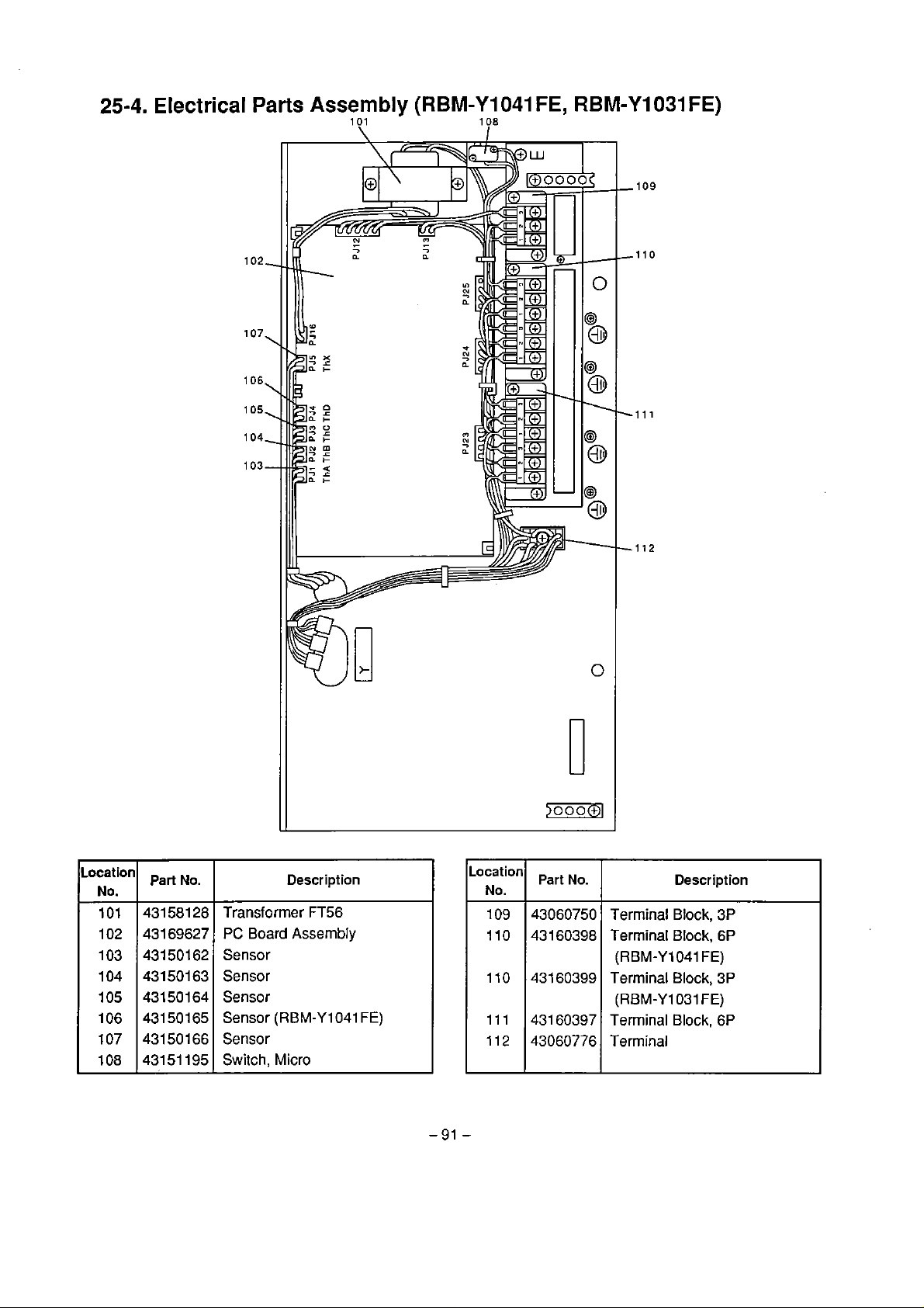
25-4. Electrical
Parts Assembly
1
O1
\
(RBM-Y1041
108
I
FE,
RBM-Y1031
FE)
Locat
No.
101
102
103
104
105
106
107
108
ion
Part
431 581
431 69627
43150162
43150163
43150164
43150165
43150166
43151 195
No.
Transformer FT56
28
PC
Board
Sensor
Sensor
Sensor
Sensor
Sensor
Switch,
Description
Assembly
(RBM-Yl041
Micro
FE)
Location
No.
109
1 10
1 10
1 11
1 12
Part
No.
43060750
43160398
431 60399
431 60397
43060776
Descript ion
Terrninal Block, 3P
Terminal
(RBM-Y1041
Terrninal Block,
(RBM-Y1031
Terrninal Block,
Terminal
Block,
FE)
FE)
6P
3P
6P

This
page
-92
is
not
-
printed.

TOSHIBA
1
-1.
SHIBAURA
1
€HOME.
CORpORATION
MINATO-KU. TOKYO
1
05.
JAPAN
 Loading...