

Page 1

A90-0233
Super Multi System
Service Manual
Air Conditioner - Multi Split Type System
HFC R407C
Page 2

Contents
Introduction
Precautions .......................................................................................................................................... 4
Components ......................................................................................................................................... 6
Outline of control system ...................................................................................................................... 9
Parts specification
Outdoor unit - general ......................................................................................................................... 12
Outdoor unit - refrigeration parts ......................................................................................................... 13
Outdoor unit - inverter assembly......................................................................................................... 14
Multi Controller - general .................................................................................................................... 15
Construction views
Outdoor unit........................................................................................................................................ 16
Multi Controller ................................................................................................................................... 17
Wiring diagram
Outdoor unit........................................................................................................................................ 18
Multi Controller ................................................................................................................................... 20
Refrigeration schematic
Outdoor unit........................................................................................................................................ 21
Normal operation - heat mode ............................................................................................................ 22
Normal operation - cool mode ............................................................................................................ 23
Simultaneous operation - mainly heat ................................................................................................. 24
Simultaneous operation - mainly cool ................................................................................................. 25
Diagnostic procedure
Diagnostic - outdoor unit ..................................................................................................................... 26
Diagnostic - Multi Controller unit ......................................................................................................... 32
Fault code display
Self-diagnostic function ...................................................................................................................... 34
Troubleshooting
Fault code table .................................................................................................................................. 36
Diagnostic procedure for check code ................................................................................................. 37
Control features ..................................................................................................................................... 63
Valve and sensor function and operation
Multi Controller valve function and operation ...................................................................................... 65
Outdoor unit valve functions ............................................................................................................... 66
Manual operation of valves ................................................................................................................. 67
Sensor and switch operation .............................................................................................................. 68
Refrigeration pipe installation
Leak test ............................................................................................................................................. 69
Vacuuming ......................................................................................................................................... 70
Charging ............................................................................................................................................. 71
Piping ................................................................................................................................................. 72
Additional refrigerant .......................................................................................................................... 73
Service parts list
Outdoor unit exploded views .............................................................................................................. 74
Inverter exploded view........................................................................................................................ 77
Multi Controller exploded view ............................................................................................................ 78
Multi Controller electrical parts ........................................................................................................... 79
3
Page 3

Introduction
Precautions
Please read these instructions carefully before starting the installation.
This equipment should only be installed by suitably trained operatives.
In all cases ensure safe working practice: Observe precautions for persons in the vicinity of the works.
Ensure that all local, national and international regulations are satisfied.
Check that the electrical specifications of the unit meet the requirements of the site.
Carefully unpack the equipment, check for damage or shortages. Please report any damage immediately.
Model MAR-F105HTM8-PE complies with the following EU Directives:
73/23/EEC (Low Voltage Directive), 89/336/EEC (Electromagnetic Compatibility) and 97/23/EC (Pressure
Equipment Directive). Accordingly, they are designated for use in commercial and industrial environments.
97/23/EC Pressure Equipment Directive information
Conformity assessment procedure: Module D1
Pressure equipment:
Compressor, category II, Module A1 Liquid receiver, category II
Accumulator, category I High pressure switch, category II, Module A1
Notified body for inspection and quality assurance systems: BSI, Maylands Avenue, Hemel Hempstead,
WP2 4SQ, UK.
Avoid installation in the following locations:
Where there is danger of flammable gas leakages.
Where there are high concentrations of oil.
Where the atmosphere contains an excess of salt (as in coastal areas). The air conditioner is prone to
failure when used under this condition unless special maintenance is provided.
Where the airflow from the outdoor unit may cause annoyance.
Where the operating noise of the outdoor unit may cause annoyance.
Where the foundation is not strong enough to fully withstand the weight of the outdoor unit.
Where the water drainage may cause a nuisance or a hazard when frozen.
Where strong winds may blow against the air outlet of the outdoor unit.
Precautions for R407C outdoor units
R407C outdoor units use synthetic oils which are extremely hygroscopic. Therefore ensure that the
refrigerant system is NEVER exposed to air or any form of moisture.
Mineral oils are unsuitable for use in these units and may lead to premature system failure.
Use only equipment which is suitable for use with R407C. Never use equipment which has been used
with R22.
R407C should only be charged from the service cylinder in the liquid phase. It is advisable to use a
gauge manifold set equipped with a liquid sight glass fitted in the centre (entry) port.
4
Page 4
Introduction
Precautions
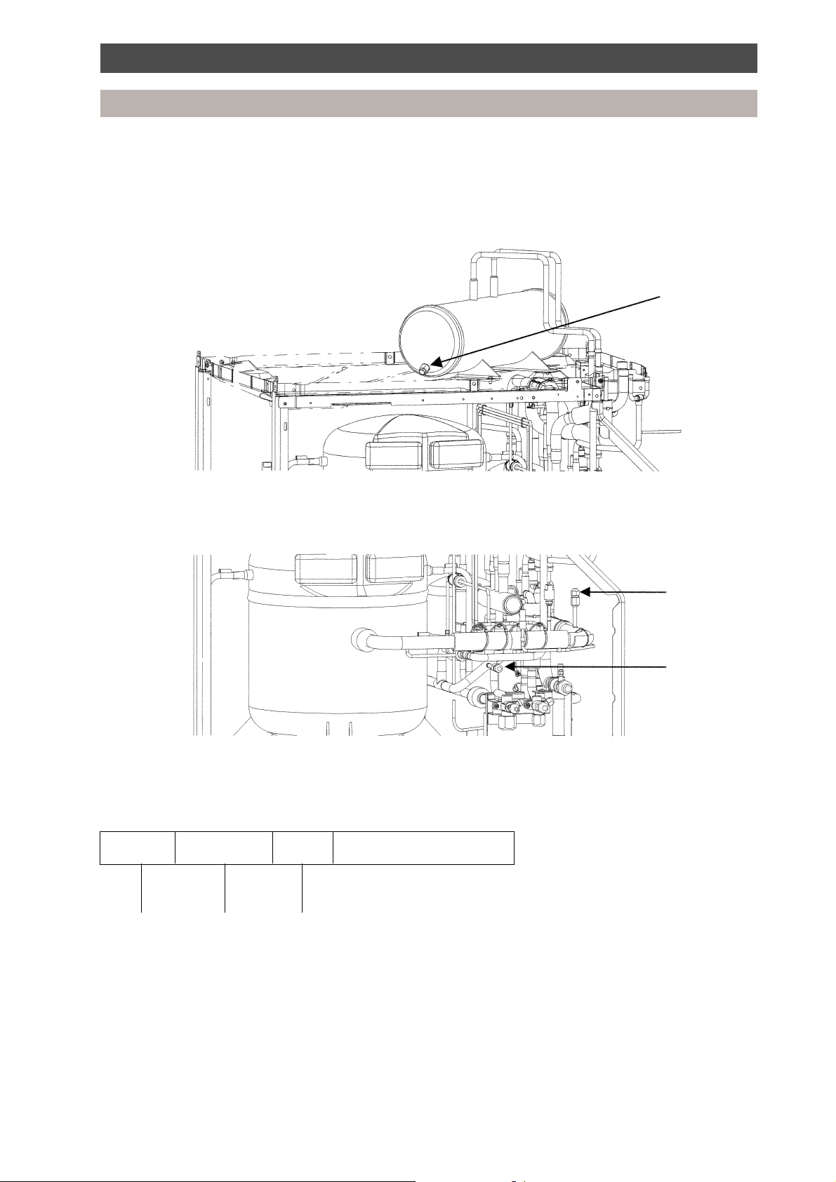
Precautions for R-407C outdoor units
Liquid receiver fusible plug
In the event of the system being subjected to abnormal conditions it is protected by a fusible plug,
positioned on the liquid receiver, within the outdoor unit. It is rated to fail at 70°C.
Position of
fusible plug
System pressure measurement
To measure the system’s high and low pressures, connect a gauge manifold to the corresponding access
port as indicated below.
Low pressure
access port
High pressure
access port
Explanation of Toshiba serial number
A serial label is attached to all Toshiba air conditioning units. Located on the label is an 8-digit number,
which represents the month, year and batch number of the manufactured unit. A breakdown of the 8-digit
number is defined below.
24480001
}
j jj
Year of
manufacture
2001 = 1
2002 = 2
2003 = 3
Month of
manufacture
41 = Jan.
42 = Feb.
43 = Mar.
44 = Apr.
45 = May
46 = Jun.
47 = Jul.
48 = Aug.
49 = Sep.
50 = Oct.
51 = Nov.
52 = Dec.
Site of
manufacture
8 = Plymouth
Model batch serial number
5
Page 5
Introduction
Components
Components - 3 pipe system
1. Outdoor unit
Model name Inverter unit
MAR-F105HTM8-PE 10 HP
2. Multi Controllers
Model name No. of indoor units connectable
RBM-Y1034F-PE 3
RBM-Y1044F-PE 4
3. Interface control kit
Model name Requirement
RBC-16DIF1-PE 3 or 4 Multi Controllers used on a system
Combination of Multi Controllers, indoor units and interface kits
No. of No. of 3-way No. of 4-way No. of
indoor units Multi Controllers Multi Controllers interface kits
1-8 1-2 Multi Controllers 0
930 1
10 2 1 1
11 1 2 1
12 0 3 1
13 3 1 2
14 2 2 2
15 1 3 2
16 0 4 2
6
Page 6

Introduction
Operating conditions
• Operating conditions of the unit are as follows:
Outdoor temperature -5 ~ 43°C Cooling
-15 ~ 21°C Heating
Room temperature 18 ~ 32°C Cooling
15 ~ 29°C Heating
Room humidity <80% Cooling
Note 1: Cooling capacity is rated at the following temperature conditions:
Indoor air inlet temperature 27°C DB, 19°C WB.
Outdoor air inlet temperature 35°C DB.
Note 2: Heating capacity is rated at the following temperature conditions:
Indoor air inlet temperature 20°C DB.
Outdoor air inlet temperature 7°C DB, 6°C WB.
Note 3: For details about the outdoor unit, indoor units or remote controller installation refer to the relevant
literature, i.e. Installation Instructions supplied with the units.
Note 4: Operatives handling refrigerants must be suitably qualified in accordance with local and national
codes of practice and statutory requirements.
Note 5: Legislation may regulate the removal of waste refrigerant from the systems. We advise
awareness of any regulations and duty of care. Waste refrigerant must NEVER be discharged to
atmosphere.
Note 6: Electrical work should be in accordance with all relevant codes of practice and should be carried
out by suitably qualified personnel.
Note 7: Metric/Imperial pipe conversion.
Diameter (mm) 6.4 9.5 12.7 15.9 19.0 22.0 28.6
Nominal diameter (inch) 1/4 3/8 1/2 5/8 3/4 7/8 1-1/8
Note 8: Within this manual:
ODU = Outdoor Unit IDU = Indoor Unit
R/C = Remote Controller D.O.L. = Direct On-Line compressor
INV = Inverter ODU WB = Wet Bulb
DB = Dry Bulb IOL = Inner Overload Relay
Mg-Sw = Magnetic Contactor IGBT = Inverter Gate Bi-Polar Transistor
OCR = Over Current Relay IPDU = Intelligent Power Drive Unit
M/C = Multi Controller
Note 9: MPaG ⇒ kgf/cm2G conversion multiplier
1.0 MPaG = 10.2 kgf/cm2G
7
Page 7
Introduction
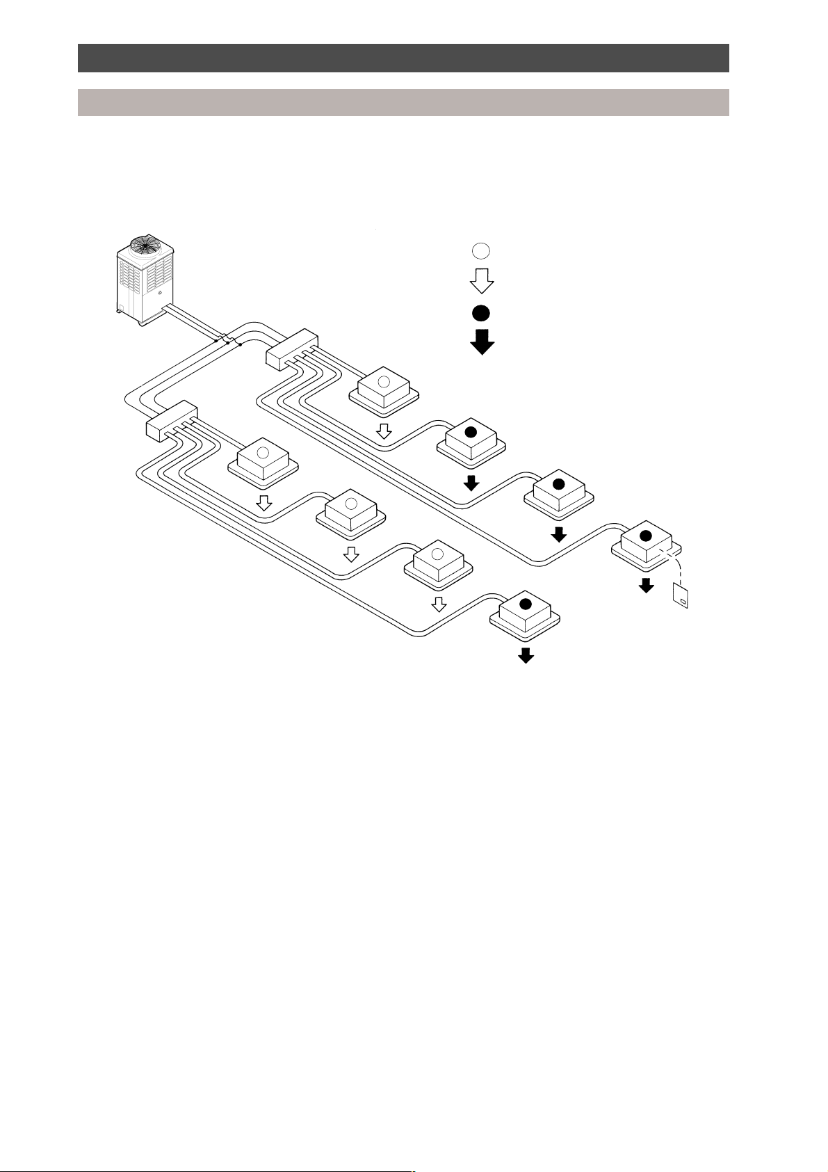
Super multi system basic components
3-pipe heat pump with simultaneous heating and cooling
This system allows separate operation of each indoor unit in either heating or cooling simultaneously.
3 pipes
3-pipe
outdoor unit
T-pieces
Multi Controller
Indoor unit remote controller requesting cooling
Cooling operation
Indoor unit remote controller requesting heating
Heating operation
Indoor units
Remote controller
2 pipes
8
Page 8
Introduction
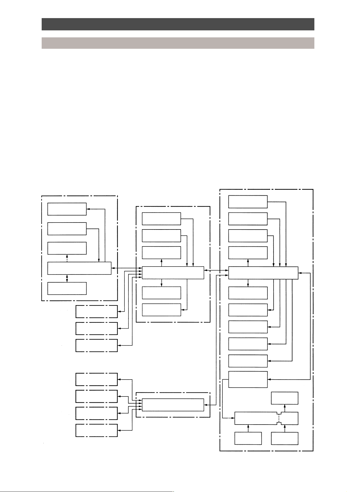
Outline of control system
The refrigerant and electrical systems of the Super Multi air conditioner are controlled by the Multi
Controller and the outdoor unit microprocessors.
All RAV heat pump, R-407C, 4/5 series indoor units are compatible with the Super Multi system, i.e. 1~5 HP.
For system operation, initially the microprocessor in each indoor unit calculates the difference between the
current room temperature (TA) and the requested temperature which has been set on the remote
controller. A demand signal is determined and transmitted to the Multi Controller microprocessor in the
form of operation commands (i.e. ON/OFF, cooling or heating operation mode, operation demand frequency).
The Multi Controller microprocessor receives operation commands from all indoor units connected,
calculates the accumulative operation command and transmits this information to the outdoor unit interface
microprocessor.
The interface microprocessor calculates the capacity required for heating or cooling and determines the
operation mode of the outdoor unit and the actual frequency of the compressor.
Control system diagram
Indoor unit 1-A
Fan
Temp. sensor (TA)
Drain pump
Indoor unit microprocessor
Remote controller
1 - B
1 - C
1 - D
Multi Controller 1
Capacity rank
setting switch
Pulse modulating
valve
Display LED
2-way valve
Outdoor unit
Protection unit
Comp. sensor
Temp. sensorTemp. sensor
Pulse modulating
valve
Interface microprocessorMulti Controller microprocessor
D.O.L. compressor
Display LED
2-way valve
Fan
2 - A
2 - B
2 - C
2 - D
Multi Controller 2
Multi Controller microprocessor
4-way valve
Communication
PCB
IPDU
Protection
unit
Inverter
compressor
Inverter
Power
supply
9
Page 9

Introduction
Components
Setting of indoor unit capacity codes
• The setting of the indoor unit capacities is important. Set the correct indoor unit code numbers
according to the indoor unit capacity. The capacities are set by the rotary switches on the printed
circuit board switch A (unit A), switch B (unit B), switch C (unit C) and switch D (unit D).
• During manufacture, the indoor capacity selection switches are set at ‘0’.
• Record the indoor capacity codes, indoor unit model names and locations in the installation manual,
and on the wiring diagram on the electrical panel cover.
Example: Room A Room B Room C
Capacity 16 Capacity 16 Capacity 26
Indoor unit Capacity No connection 10 13 16 20 26 36 46
Code number 0 2 3 4 5 6 8 10
(Example: Model RAV-364UH-PE, capacity = 36)
Multi Controller PCB
MCC-1210
Capacity select switches
• Multiple indoor units may be connected to each outdoor unit, providing the total indoor code does not
exceed the limits shown below.
Combination of Multi Controllers and indoor units
Number of Maximum No. of Indoor unit diversity Maximum system code Maximum code per
Multi Controllers indoor units Multi Controller
1 4 135% 27 27
2 8 160% 32 27
3 12 27 (13*)
416 13
Example of systems with maximum possible code:
Outdoor unit
Interface kit
Multi Controller [code]
(Max. system code)
10
OD OD
OD
27 266668888
27
(27) (32)(32)
OD OD
27 13
27 2713 13 13 13 13
OD
DIF
DIF DIF DIF
20
OD
OD
(32)
DIFDIF
Page 10
Introduction
Components
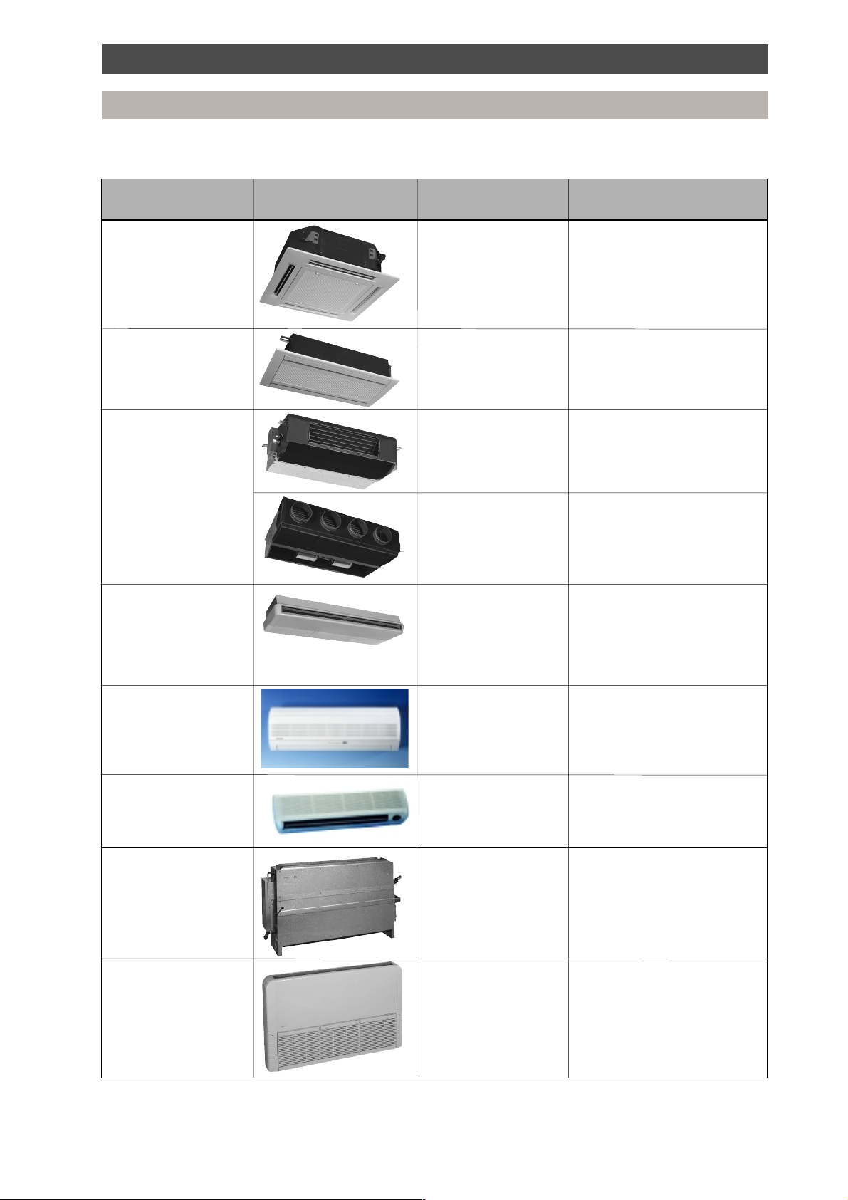
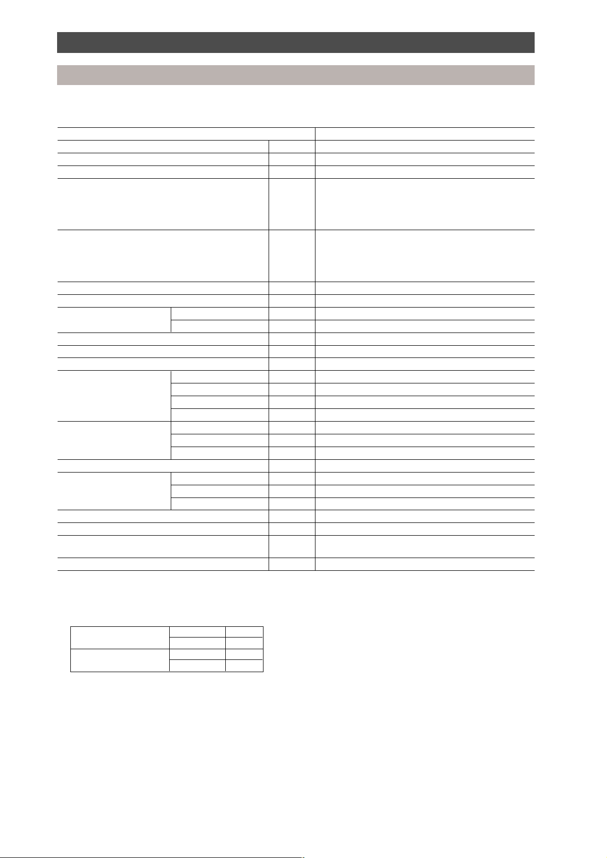
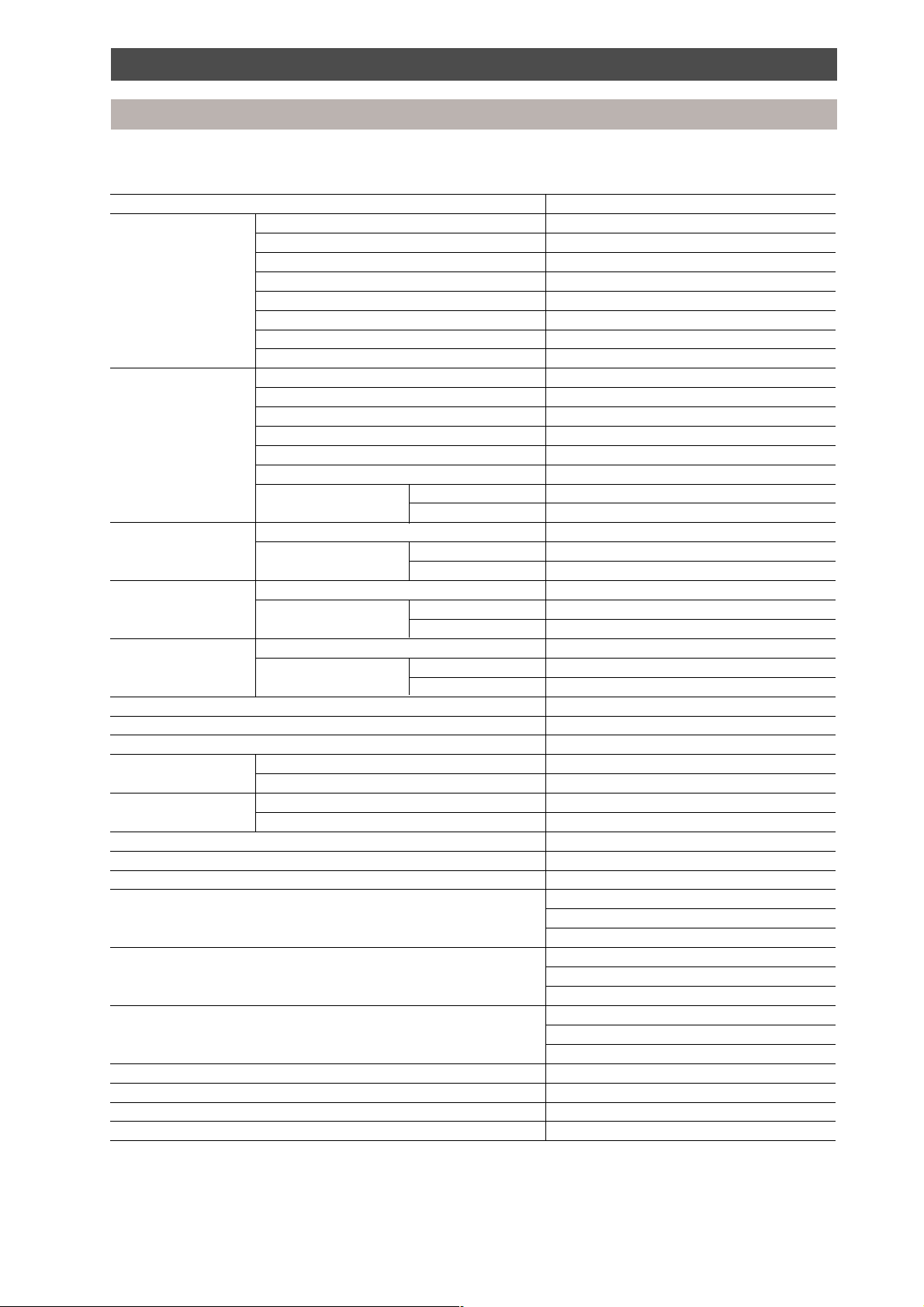
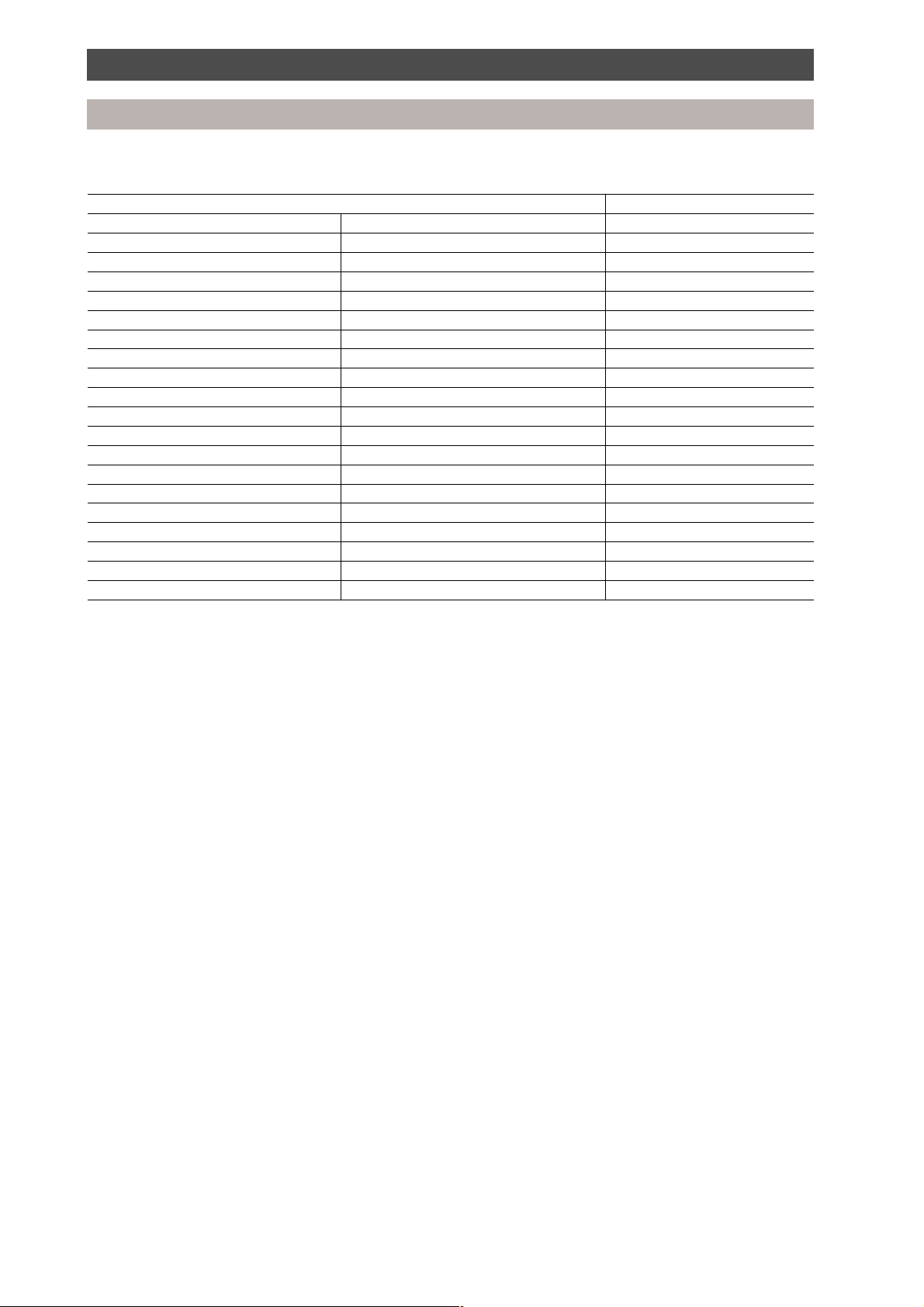
Indoor units
Type Appearance Model name Capacity code on
Multi Controller
Cassette (4-way) RAV-164UH-PE 4
RAV-264UH-PE 6
RAV-364UH-PE 8
RAV-464UH-PE 10
Cassette (2-way) RAV-104TUH-1-PE 2
RAV-134TUH-1-PE 3
RAV-164TUH-1-PE 4
RAV-104SBH-PE 2
Built-In Horizontal
RAV-164BH-PE 4
RAV-264BH-PE 6
RAV-364BH-PE 8
RAV-464BH-PE 10
Ceiling Suspended RAV-134CH/CHR-PE 3
RAV-164CH/CHR-PE 4
RAV-264CH/CHR-PE 6
RAV-364CH/CHR-PE 8
RAV-464CH/CHR-PE 10
High Wall RAV-105KH-E 2
RAV-135KH-E 3
RAV-165KH-E 4
RAV-265KH-E 5
High Wall RAV-264KH-PE 6
Built-In Vertical RAV-104NH-PE 2
RAV-134NH-PE 3
RAV-164NH-PE 4
RAV-264NH-PE 6
Floor Mounted RAV-164SH/SHR-PE 4
RAV-264SH/SHR-PE 6
11
Page 11
Parts specification
Outdoor unit
Specification of 3-pipe, heat recovery outdoor unit
Model name MAR-F105HTM8-PE
Cooling capacity kW 25.0 (28.0)
Heating capacity kW 28.0 (31.5)
Power supply 380-415 V, 3 phase, 50 Hz
Cooling
Operating current A 17.4 (19.1)
Power consumption kW 11.8 (12.8)
EER 2.11 (2.19)
Power factor % 98 (97)
Heating
Operating current A 17.7 (15.5)
Power consumption kW 11.8 (10.5)
COP 2.37 (3.0)
Power factor % 96 (98)
Starting current A 60
Starting method Direct
Sound level Sound pressure dB 58
Sound power dB(A) 70
Dimensions (H x W x D) mm 1700 x 990 x 790
Net weight kg 285
Colour Silky Shade (Munsell 1-Y8.5/0.5)/RAL 1013 (DE ~9)
Compressor Type Hermetically sealed (twin scroll)
Oil (volume) ml Polyolester NISSEKI RB74AF 74VG (7000)
Crankcase heater Internal type
Motor output kW 7.5
Fan assembly Fan Propeller fan
Motor output kW 0.4
Air flow volume m3/h 10,000
Refrigeration (charged weight) kg R-407C (19)
Piping connection Liquid mm 15.9 (flare connection)
Discharge gas mm 19.0 (flare connection)
Suction gas mm 28.6 (brazing connection)
Max. equivalent piping length m 120
Max. actual piping length m 100
Max. piping head m 50: when the outdoor unit is installed above
Suction accumulator case heater W 29 (240 V AC)
m 20: when the outdoor unit is installed below
Notes:
1. Specifications are subject to change without notice.
2. The specification shown in ( ) denotes operation with an indoor unit load diversity of 135%.
3. Operating conditions:
Outdoor temperature °C Cooling -5 to 43
Heating -15 to 21
Room temperature °C Cooling 18 to 32
Heating 15 to 29
4. Sound level: 1 m horizontal from centre.
1.5 m vertical from base.
12
Page 12
Parts specification
Outdoor unit
Specification of outdoor unit refrigeration cycle parts
Parts description MAR-F105HTM8-PE
Compressor model Model name MG1300CW-20
Motor type 3-phase induction motor
Power supply 380-415 V, 3 phase, 50 Hz
Output kW 7.5
Pole 2/2 (inverter side/non-inverter side)
Coil resistance Ω 1.49/2.51 (inverter side/non-inverter side)
Compressor oil name Polyolester NISSEKI RB68AF VG 74
Amount of oil ml 7,000
Fan motor Model name STF-200-350A
Motor type 1-phase, induction type
Power supply 220-240 V, 1 phase, 50 Hz
Output kW 0.4
Supply current A 3.2 ~ 3.5
Pole 6
Protective device Operation °C 145 ± 5
(Relay) Reset °C 86 ± 15
High pressure switch Model name ACB-JB128
Inverter side Operating pressure Operation MPa 3.2
Reset MPa 2.55
High pressure switch Model name ACB-JA64
Fixed side Operating pressure Operation MPa 3.2
Reset MPa 2.55
Low pressure switch Model name 20PS-1
Operating pressure Operation MPa 0.025
Reset MPa 0.15
4-way valve CHV-0712, coil AC240 V
Liquid tank l (RSH 12) 12
Accumulator l (BT9-1 1/8)
Check valve Model name YCV5-3SPTF-1
Maximum pressure MPa 3.3
Check joint Model name R-407C type
Maximum pressure MPa 3.53
Expansion valve EXV-V-E80HTF-9WS
Compressor heater (Internal within the compressor)
Accumulator heater W 29 (240 V AC)
Pressure sensor Model name: NTP-Q250TF-2
Input voltage: DC12 V
Output voltage: DC 0.5 - 4.5 V
Discharge temperature sensor 25°C = 50 kΩ
50°C = 18.1 kΩ
100°C = 3.35 kΩ
Suction temperature sensor/ 0°C = 34.6 kΩ
outdoor air temperature sensor 25°C = 10 kΩ
50°C = 3.4 kΩ
Pulse modulating valve (Cooling bypass PMV1) EV18RC1, coil DC 12 V
Pulse modulating valve (PMV2) EV23RC2, coil DC 12 V
2-way valve (SV1, SV2, SV4, SV5, SV16, SV17) NEV202DXF, coil AC 240 V
2-way valve (SV13, SV14, SV15) RP100-03, coil AC 240 V
Note:
Specifications are subject to change without notice.
13
Page 13
Parts specification
Outdoor unit
Specification of outdoor unit inverter assembly parts
Model name MAR-F105HTM8-PE
Power supply 380-415 V, 3 phase, 50 Hz
PC board assembly PCB (IPDU) MCC-1342
PC board assembly PCB (noise filter) MCC-1366
PC board assembly PCB (interface) MCC-1223
PC board assembly PCB (communication) MCC-1387
Fan motor capacitor 8 µF/450 V AC
Electrolytic capacitor 2200 µF/400 V
Power supply terminal plate L1, L2, L3 600 V AC, 60 A, 3 pole
Transformer Interface TT01
Magnetic contactor Inverter side FMCa - 1S
Magnetic contactor Fixed side FC - 3
Reactor CH - 25 - 2FK
Fuse 6 A 500 V AC
Fuse 20 A 600 V AC
Fuse 3.15 A 250 V AC
Fuse 6.3 A 250 V AC
Fuse 20 A 250 V AC
Fuse 10 A 250 V AC
Thermistor (PTC)
Relay 15 A, 240 V AC
Note:
Specifications are subject to change without notice.
14
Page 14
Parts specification
Multi Controller unit
Specification of 3-pipe Multi Controller parts
Model name RBM-Y1034F-PE RBM-Y1044F-PE
Pulse modulating valve EV23RC7, coil DC 12 V
Temperature sensor At 0°C = 32.8 kΩ, 25°C = 10 kΩ, 50°C = 3.6 kΩ
Float switch FS-085-0031
PC board assembly PCB MCC-1222
Power supply transformer Model name FT69
Specification Primary side: AC 240 V, secondary side: AC 12 V
Relay (PC board) G2R-117P, coil DC 12 V
Heater 10.4 W/m
50 W 65 W
Thermal fuse for heater Cut out at 119°C
Heater fuse T1A
Discharge gas side 2-way valve RP100-03, coil AC 240 V
Suction gas side 2-way valve REV-1506DXFQ6, coil AC 240 V
2-way valve NEV202DXF-AC 240 V
2-way valve NEV603DXF-AC 240 V
Note:
Specifications are subject to change without notice.
15
Page 15

MAR-F105HTM8-PE
Dimensional drawings
Construction view
Outdoor unit
4-15 x 20 (Slot)
80
790755
630
Grounding part of bottom plate
4 - ø 25
drain holes
1700
1582
110
700
80
Fixing bolt positions
Fixing bolt pitch
90
700
990
Pipe outlet
(bottom)
601
Grounding part of bottom plate
Foundation dimensions
750
88
4-60 x 150 slot
(for transport)
All dimensions in mm
16
568
500
Slot pitch
Details of piping connections
Knock outs on
both sides of unit
Refrigerant pipe connecting port
(Gas suction side) braze connection (ø 28.6)
Refrigerant pipe connecting port
(Liquid side) flare connection (ø 15.9)
315
275
1146068
Refrigerant pipe connecting port (gas
discharge side) flare connection (ø 19.0)
3-ø 20 cable gland knock outs
ø 32 cable gland knock outs
ø 25 cable gland knock outs
Page 16

Construction view
Multi Controller
Model A B C D E F
RBM-Y1034F-PE 460 300 - 90 - 90
RBM-Y1044F-PE 530 370 90 90 90 90
All dimensions are in mm
2 notches for
hanging bolts
(12 x 21)
Electric parts box
Refrigerant pipe
connection (brazing)
55
Liquid side ø 12.7
55
50
80
300
300
A
D
C
EF
90
90
2 slots for
hanging bolts
(12 x 52)
3-pipe:
RBM-Y1034F/Y1044F-PE
Connection (brazing)
Liquid side ø 15.9
Wiring knockouts
6 x ø 20
110
Refrigerant pipe
connection (brazing)
Gas side ø 19
Refrigerant pipe
connection (brazing)
Delivery gas side ø 19
Refrigerant pipe
connection (brazing)
Suction gas side ø 28.6
17
Page 17
MAR-F105HTM8-PE
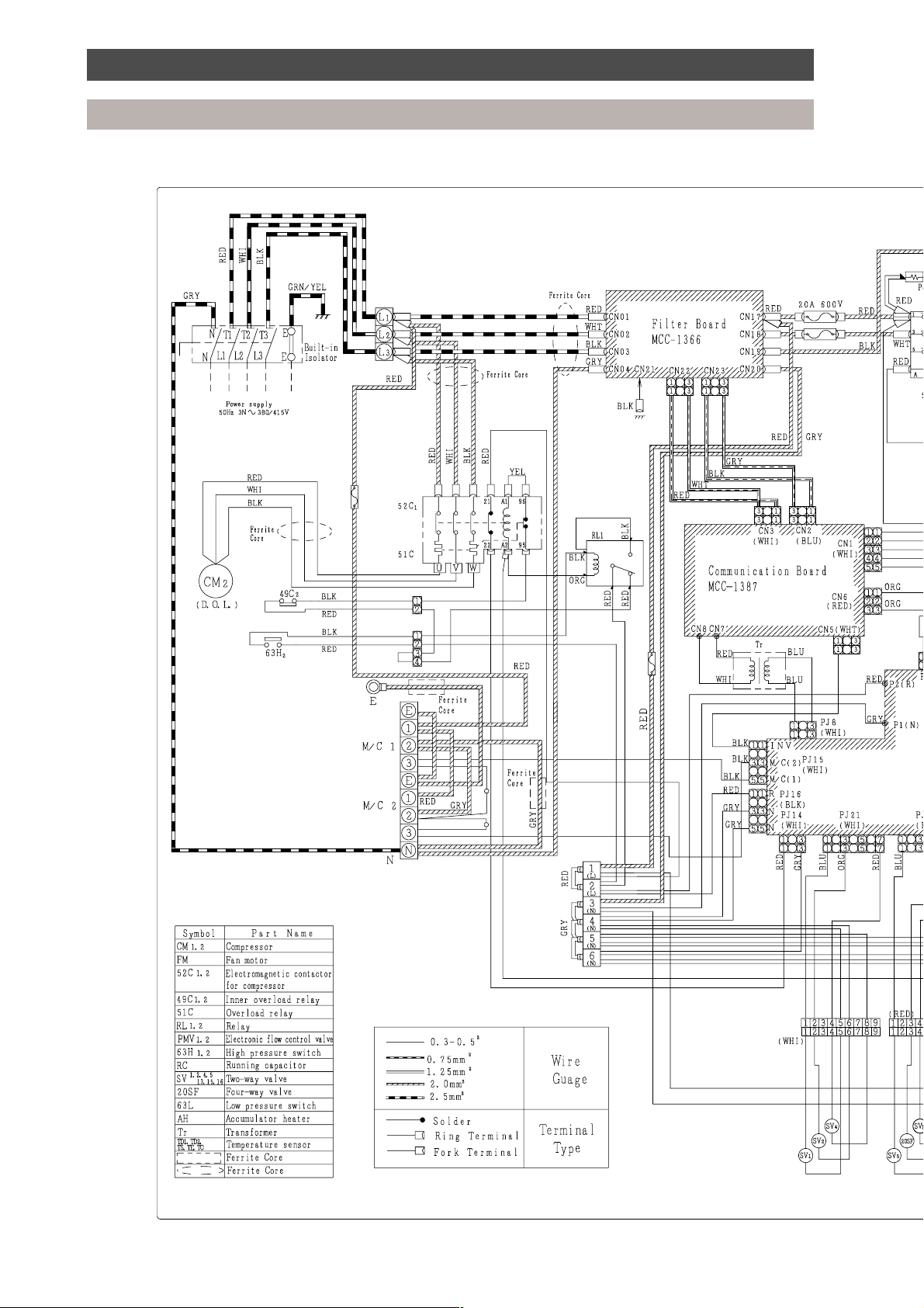
Wiring diagrams
Outdoor unit
18
Page 18
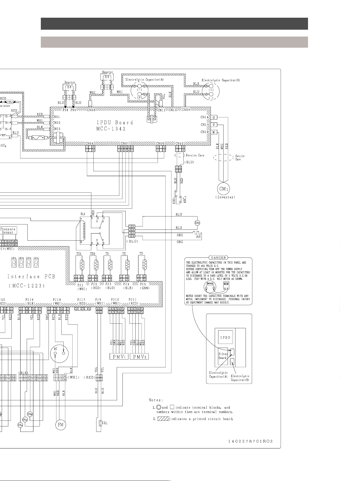
Wiring diagrams
Outdoor unit
19
Page 19
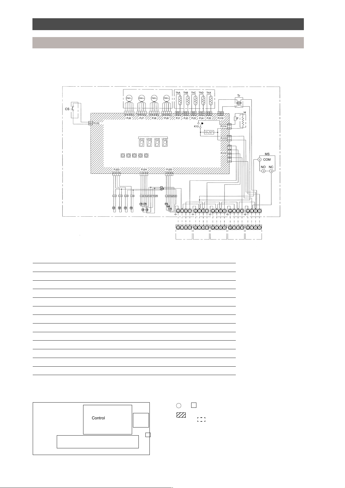
Wiring diagram
Multi Controllers
3-pipe Multi Controller (RBM-Y1034F-PE, RBM-Y1044F-PE)
Spark
killer
Capacity rank
setting
ABCD
7-segment LED
Display
selector switch
Indoor
unit A
Indoor
unit B
Indoor
unit C
Symbol Part Name
PMVA, B, C, D Pulse modulating valve
Th A, B, C, D, X Temperature sensor
Tr Power transformer
CS Float switch
H Heater
MS Reset switch
F Fuse (T1A)
SVD (A), (B), (C), (D) Electrically operated valve for discharge gas side
SVD (A), (B), (C), (D) Electrically operated valve for suction gas side
SVDD Electrically operated valve for increasing pressure
SVSS Electrically operated valve for decreasing pressure
SVH Electrically operated valve for superheat control
LD 101, 102, 103, 104 Fault indicator LED
Parts layout
Control PC board
Terminal plate
Trans
• The dashed lines indicate wiring on site.
• and indicate terminal blocks, and numbers within them are
terminal numbers.
• indicates a printed circuit board.
• The frame indicates the product body.
• RBM-Y1034F-PE does not have PMVD, SVD(D), SVS(D), ThD or the
Reset
switch
connection block for indoor unit D.
The capacity rank code setting for unit D is to be set to “0”.
Indoor
unit D
Outdoor
unit
20
Page 20
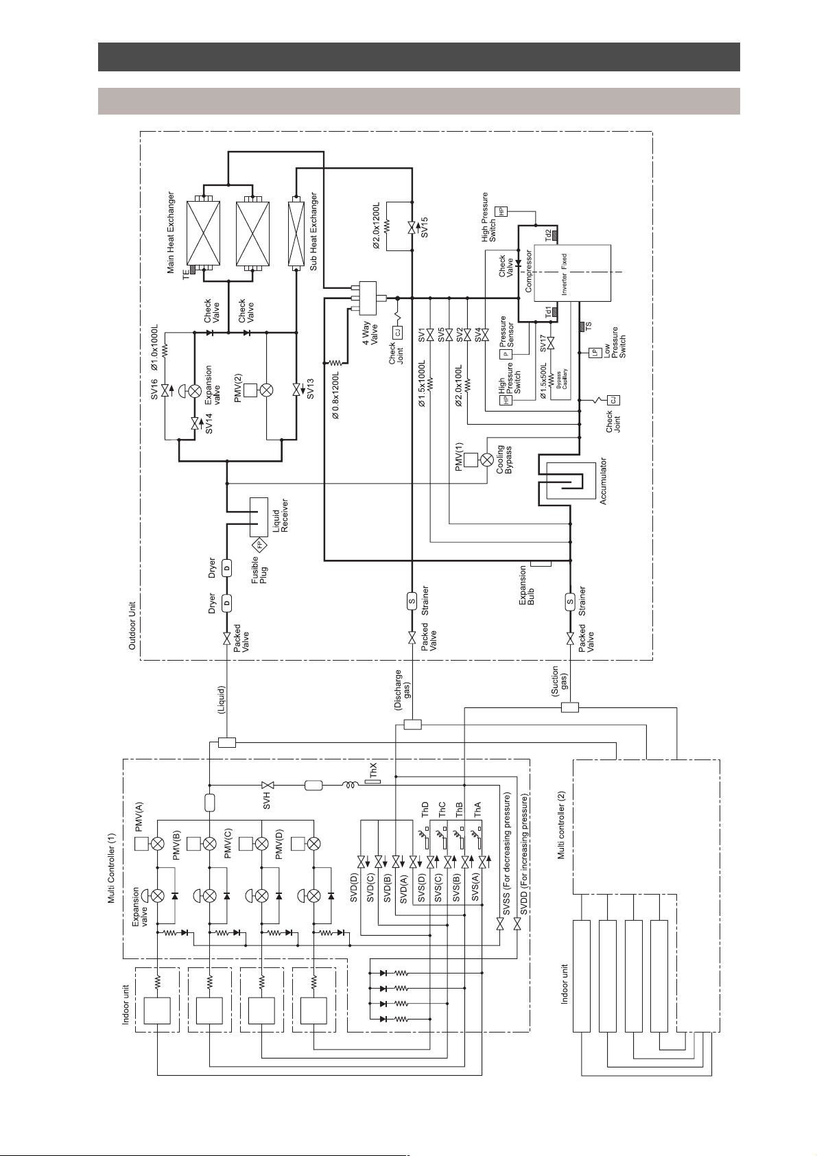
Refrigeration piping schematic diagram
Outdoor unit
21
Page 21

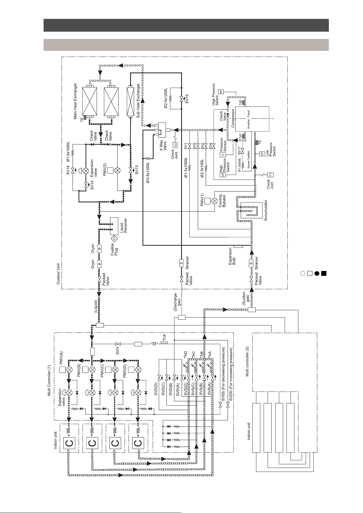
Refrigeration piping schematic diagram
Normal operation - heat mode
High pressure gas
Low pressure gas
Key:
High pressure liquid
Low pressure liquid
22
Page 22
Refrigeration piping schematic diagram
Normal operation - cool mode
High pressure gas
Low pressure gas
Key:
High pressure liquid
Low pressure liquid
23
Page 23
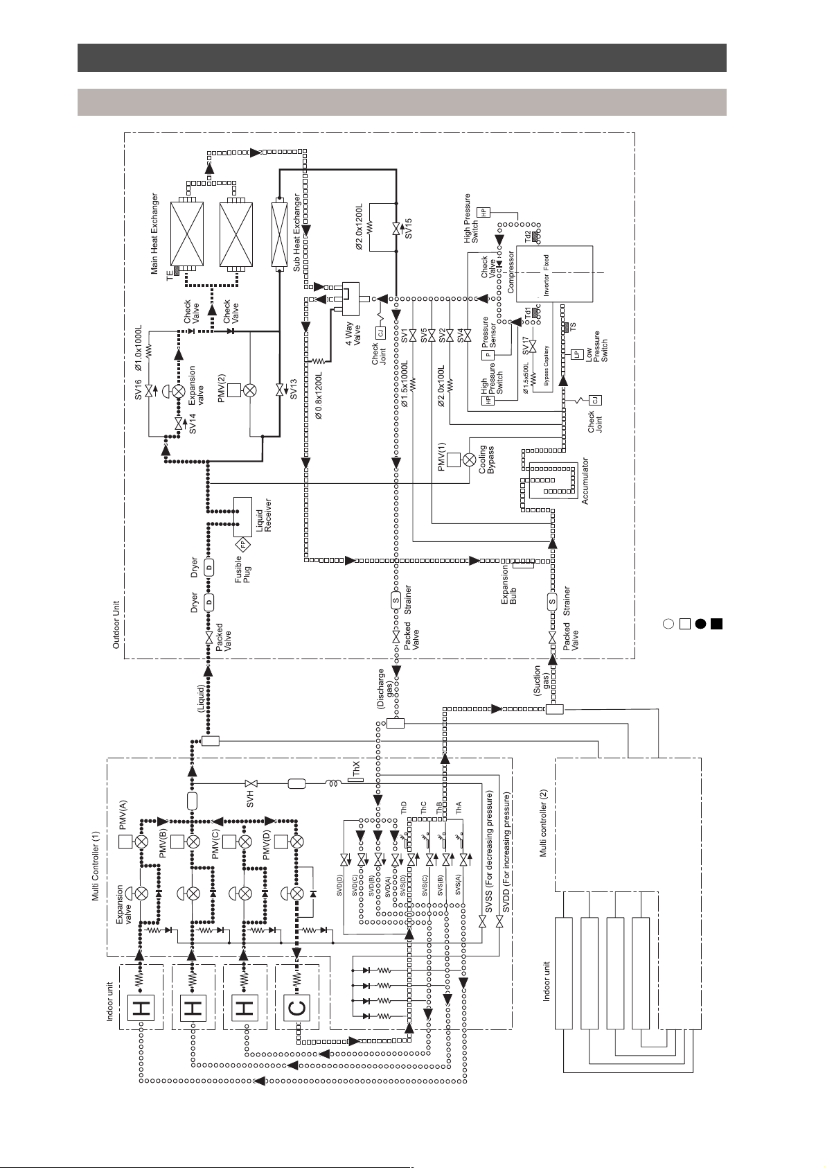
Refrigeration piping schematic diagram
Simultaneous operation - mainly heat
High pressure gas
Low pressure gas
Key:
High pressure liquid
Low pressure liquid
24
Page 24
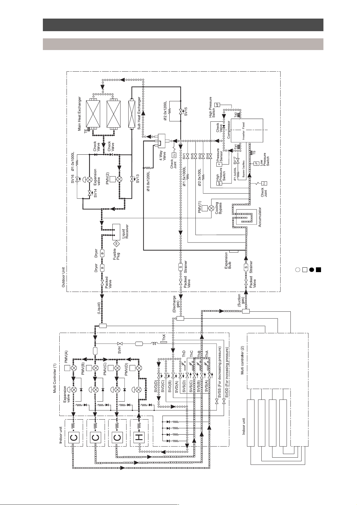
Refrigeration piping schematic diagram
Simultaneous operation - mainly cool
High pressure gas
Low pressure gas
Key:
High pressure liquid
Low pressure liquid
25
Page 25

Diagnostic procedure
Outdoor unit
MAR-F104HTM8-PE, 3-pipe outdoor unit
Malfunction judgement is performed using the self-diagnostic function of the outdoor unit. The combination
of the display switches (SW1, SW2) and the LEDs (LD 71~LD 74) indicates the diagnostic details.
Located on the electrical inverter cover is a transparent window, which allows the 7-segment LED to be
viewed while the unit is in operation.
The transparent window has access holes to allow the adjuster pen, which is attached to the window,
access to alter the setting of the display switch SW1 and SW2 while the unit is running.
A slit is positioned at one end of the pen to locate onto the rotary switch.
The adjuster pen can also be used to push switches SW3 and SW4 during the diagnostic procedure
check.
A crimp connector is located on the other end of the adjuster pen. This connector can be used to ‘short’
TP1 or TP2 connectors when performing manual operation of the outdoor valves.
No other component other than that supplied must be used to adjust the rotary switches. Failure to do
so may result in damage to the unit, malfunction or risk of electric shock.
26
Page 26

Diagnostic procedure
Outdoor unit
1. Communication serial signals and the system operating status are displayed by changing display
switch SW2.
Display Display Indication 7-segment LED display
switch switch LD 71 LD 72 LD73 LD74
SW1 SW2
position position
0 0 Sending/receiving status of Between Between Between Non-inverter
interface control board serial M/C (1) M/C (2) inverter compressor
signal Sending Not sending Abnormal [E]
only [S] or receiving
[ ]
Receiving Sending and Normal [0]
only [J] receiving [0]
1 Operating instruction Operating Heating [H], Simultaneous ---------- ----------
from M/C (1) mode cooling/heating [HC],
Cooling [C], Stop [ ]
2 Instruction Heating frequency [00-1F] Cooling frequency [00-1F]
frequency (Refer to conversion table 2) (Refer to conversion table 2)
3 Outdoor unit Operating Heating [H], Cooling [0C], ---------- ----------
operating condition mode Simultaneous heating [Hc]
Defrost [J0], Simultaneous
cooling [hC]
4 M/C Frequency ---------- ----------
operation release
Off: [0] No: [0]
1 unit: [1] Yes: [1]
2 unit: [2]
5 Operating instruction Operating Heating [H], Simultaneous ---------- ----------
from M/C (2) mode cooling/heating [HC],
Cooling [C], Stop [-]
6 Instruction Heating frequency [00-1F] Cooling frequency [00-1F]
frequency (Refer to conversion table 2) (Refer to conversion table 2)
9 Inverter operation status Normal Operating ---------- ----------
[C] frequency
[0-F],
Abnormal (Refer to
[E] table 3)
10 Operating instruction to Normal Operating ---------- ----------
inverter from interface [C] frequency
control board [0-F],
Abnormal (Refer to ---------- ---------[E] table 3)
11 Power supply frequency 50 Hz [5] [0] ---------- ----------
60 Hz [6]
27
Page 27

Diagnostic procedure
Outdoor unit
2. Display code conversion table - instruction frequency from Multi Controller.
Display 00 01 02 03 04 05 06 07 08 09 0A 0B 0C 0D 0E 0F
code
Frequency 0 0 0 3.9 6.9 10.0 13.0 16.2 19.3 22.4 25.5 28.6 31.7 34.8 37.9 41.0
conversion
value (Hz)
Display 10 11 12 13 14 15 16 17 18 19 1A 1B 1C 1D 1E 1F
code
Frequency 44.1 47.2 50.3 53.4 56.5 59.6 62.7 65.8 68.9 72.0 75.1 78.2 81.3 84.4 87.5 90.0
conversion
value (Hz)
3. Display code conversion table - operating frequency of inverter compressor
Display 03456789ABCDEF
code
Frequency 0 30.5 38.3 41.9 45.5 53.3 61.0 68.8 76.0 83.8 91.6 102.9 110.7 121.5
conversion
value (Hz)
4. PMV opening information is displayed
Display Display Indication 7-segment LED display
switch switch LD 71 LD 72 LD 73 LD 74
SW1 SW2
position position
1 2 PMV1 opening [P] [1] Displays the degree of PMV
opening (0 - 240) as a
hexadecimal code:
3 PMV2 opening [P] [2] [00] : Closed, [F0] : Fully open
5. Malfunction information is displayed, refer to fault code section for details
Display Display Indication 7-segment LED display
switch switch LD 71 LD 72 LD 73 LD 74
SW1 SW2
position position
2 0 Check code [E] Outdoor unit: [r] Refer to fault code section for
display for the M/C (1): [1] details (page 36)
outdoor unit, M/C (2): [2]
M/C (1), M/C (2)
28
Page 28

Diagnostic procedure
Outdoor unit
6. The indoor unit capacity rank setting is displayed.
Display Display Indication 7-segment LED display
switch switch LD 71 LD 72 LD 73 LD 74
SW1 SW2
position position
3 0 Outdoor unit HP [9] 8 HP [8], 10 HP [A] [H] [P]
1 Capacity rank of Unit A [A] Displays the code number of the
2 indoor unit Unit B [b] indoor unit registered to each M/C.
3 connected to Unit C [C]
4 M/C (1) Unit D [d] Refer to the table below (7) for
5 Capacity rank of Unit A [A] indoor unit model capacity rank.
6 indoor unit Unit B [b]
7 connected to Unit C [C]
8 M/C (2) Unit D [d]
7. Indoor unit code No. conversion table
Code No. 0 23456810
Capacity rank No correction 10 13 16 20 26 36 46
(Indoor unit model example: Model RAV-364UH-PE, capacity rank = 36)
8. Sensor temperature display
Display Display Indication 7-segment LED display
switch switch LD 71 LD 72 LD 73 LD 74
SW1 SW2
position position
4 0 Pressure sensor data [P] [d] Refer to table 9 conversion chart
1 ThD1 sensor data [d] [1] Refer to table 10 conversion chart
2 ThD2 sensor data [d] [2]
3 ThS sensor data [S] [1] Refer to table 11 conversion chart
4 TE sensor data [h] [E]
5 TO sensor data [h] [0]
29
Page 29

Diagnostic procedure
Outdoor unit
9. Outdoor unit - pressure sensor data
Display Pressure Display Pressure Display Pressure Display Pressure
(kgf/cm2G) (kgf/cm2G) (kgf/cm2G) (kgf/cm2G)
17 0.0 67 11.0 96 17.5 C6 24.0
1E 1.0 6B 11.5 9A 18.0 C9 24.5
25 2.0 6E 12.0 9E 18.5 CD 25.0
2D 3.0 72 12.5 A1 19.0 D1 25.5
34 4.0 76 13.0 A5 19.5 D4 26.0
3B 5.0 79 13.5 A9 20.0 D8 26.5
43 6.0 7D 14.0 AC 20.5 DC 27.0
4A 7.0 81 14.5 BD 21.0 DF 27.5
51 8.0 84 15.0 B4 21.5 E3 28.0
58 9.0 88 15.5 B7 22.0 E7 28.5
5C 9.5 8B 16.0 BB 22.5 EA 29.0
60 10.0 8F 16.5 BE 23.0 EE 29.5
63 10.5 93 17.0 C2 23.5 F2 30.0
These are sample displays. intermediate displays to those above are possible.
10. Outdoor unit - ThD1 and ThD2 sensor data
Display Temp. °C Display Temp. °C Display Temp. °C Display Temp. °C
05 -5.0 28 40.0 7C 85.0 C6 130.0
07 0.0 30 45.0 87 90.0 CB 135.0
09 5.0 38 50.0 90 95.0 D0 140.0
0C 10.0 41 55.0 9A 100.0
0F 15.0 4A 60.0 A2 105.0
12 20.0 54 65.0 AB 110.0
17 25.0 5E 70.0 B2 115.0
1C 30.0 68 75.0 B9 120.0
22 35.0 72 80.0 C0 125.0
These are sample displays. Intermediate displays to those above are possible.
Display [00] signifies sensor open circuit.
11. Outdoor unit - ThS, TE, TO sensor data
Display Temp. °C Display Temp. °C Display Temp. °C Display Temp. °C
2A -20.0 7C 9.0 A2 22.0 C0 35.0
36 -15.0 7F 10.0 A5 23.0 C2 36.0
42 -10.0 82 11.0 A7 24.0 C4 37.0
51 -5.0 85 12.0 AA 25.0 C6 38.0
60 0.0 88 13.0 AC 26.0 C8 39.0
63 1.0 8B 14.0 AF 27.0 C9 40.0
66 2.0 8E 15.0 B1 28.0 D1 45.0
69 3.0 91 16.0 B3 29.0 D8 50.0
6C 4.0 94 17.0 B6 30.0 DE 55.0
6F 5.0 97 18.0 B8 31.0 E3 60.0
73 6.0 9A 19.0 BA 32.0 E7 65.0
76 7.0 9C 20.0 BC 33.0 EA 70.0
79 8.0 9F 21.0 BE 34.0
These are sample displays. Intermediate displays to those above are possible.
Display [00] signifies sensor open circuit.
30
Page 30

Diagnostic procedure
Outdoor unit circuit test procedure
12. Outdoor unit circuit test procedure
• These systems have a feature which enables them to check that the wiring and piping connections
are aligned with each other. This is carried out by allowing refrigerant to flow to one indoor unit at a
time and monitoring that indoor unit’s coil sensor for a corresponding drop in temperature. Each
indoor unit is tested in turn and where two Multi Controllers are installed each Multi Controller is tested
in turn.
• This test would normally be used at the commissioning stage.
• Procedure for initialising the circuit test.
1. Turn the power off.
2. Ensure the capacity codes are set correctly, capacity switches set to ‘0’ are not tested.
3. Put the outdoor display switches SW1 and SW2 to 9 and Multi Controller(s) display switch to 6.
4. Turn the power back on.
5. Set all the remote controllers to cool mode and 29°C.
6. Press the on/off button to start all the indoor units (the outdoor LEDs show ‘1020’).
7. Press the outdoor unit switch SW3, and hold for 3 seconds.
8. The system is now in self-testing (all 8 LEDs will be flashing rapidly).
9. The system will stop at the end of the test.
• In the event of cross wiring/piping the system will indicate which units are faulty, see table below:
Outdoor display switch SW1 and SW2 set to position 9.
One and two Multi Controllers
Display Multi Controller Fault
1020 All None
1A20 1 Unit A
1B20 Unit B Units that are indicated
1C20 Unit C failed the test
1D20 Unit D
102A 2 Unit A
102B Unit B
102C Unit C
102D Unit D
Three or more Multi Controllers
Display Multi Controller Fault
1020 All None
1A20 1 Unit A or B
1B20 Unit C or D Units that are indicated
1C20 2 Unit A or B failed the test
1D20 Unit C or D
102A 3 Unit A or B
102B Unit C or D
102C 4 Unit A or B
102D Unit C or D
31
Page 31

Diagnostic procedure
Multi Controller
The combination of the display switch and the four 7-segment LEDs (LD 101-LD 104) indicates the
diagnostic details.
MCC - 1223
7-segment LED
LD 101
LD 102
LD 103
LD 104
Unit B
Unit A
Capacity rank switches
Unit D
Unit C
Display switch
Multi Controller control board
7 segment LED display
Switch Indication LD 101LD 102 LD 103 LD 104
position
0 Serial - - - Receiving Sending - Sending Receiving Receiving - Receiving Sending - Sending Receiving Sending
signal from to to from from from to to from to
1 Fault [E] - Fault code display (normal [00]). Refer to fault code section for details.
codes
2 Frequency Instructed demand frequency of cooling or heating [00 - 1F].
instructions Refer to the Multi Controller display conversion table (1) for display switch position “2”
to the outdoor unit
3 Oil - - - Oil Superheat - Superheat Oil - - Oil Superheat - Superheat Oil -
retrieval, retrieval control control retrieval retrieval control control retrieval
superheat unit B unit B unit A unit A unit D unit D unit C unit C
control
Defrost Displays [dF] during defrost operation
4 Operation M/C operating Outdoor unit operating mode: Heating [H-], Cooling [-C], Simultaneous Heating [Hc],
mode mode: Simultaneous Cooling [hC], Stop [--], Defrost [J-]
5 Restart - - - Normal display [0], Restart timer counting [1]
timer
6 Circuit test [c] [k] Displays unit being tested [A b C d] Indicates faulty unit connection [A b C d]
7 PMV A [P] [A] Displays the degree of PMV opening (0-240) as a hexadecimal code:
8 PMV B [P] [b] [00]: Closed, [FO]: Fully open
9 PMV C [P] [c]
10 PMV D [P] [d]
11 ThA [h] [A] Displays sensor temperature
12 ThB [h] [b] Refer to the Multi Controller sensor temperature conversion table (1).
13 ThC [h] [c]
14 ThD [h] [d]
15 ThX [h] [H]
Heating [H-],
Cooling [C-]*
unit B unit B unit A unit A oudoor unit D unit D unit C unit C outdoor
unit unit
* and Simultaneous Cooling/Heating [HC], Defrost [J-]
32
Page 32

Diagnostic procedure
Multi Controller
1. Display switch set to position “11”, “12”, “13” and “14”
Multi Controller - ThA, B, C, D and X sensor conversion table
Display Temp. °C Display Temp. °C Display Temp. °C Display Temp. °C
18 -10.0 44 1.0 70 12.0 9C 23.0
1C -9.0 48 2.0 74 13.0 A0 24.0
20 -8.0 4C 3.0 78 14.0 A4 25.0
24 -7.0 50 4.0 7C 15.0 A8 26.0
28 -6.0 54 5.0 80 16.0 AC 27.0
2C -5.0 58 6.0 84 17.0 B0 28.0
30 -4.0 5C 7.0 88 18.0 B4 29.0
34 -3.0 60 8.0 8C 19.0 B8 30.0
38 -2.0 64 9.0 90 20.0
3C -1.0 68 10.0 94 21.0
40 0.0 6C 11.0 98 22.0
Display [00] signifies sensor open circuit.
Control board communication diagram
Multi Controller
M/C (1)
Interface
control board
I/F
Multi Controller
M/C (2)
Remote
controller
Indoor unit
A few seconds 1 minute 1 minute1 minute
Remote controller fault code display time lapse for system malfunctions
Serial signal abnormalities: Between the I/F and the INV More than 3 minutes
Between the M/C and the I/F More than 2 minutes
Between the indoor unit and the M/C More than 1 minute
Between the remote controller and indoor unit A few seconds
INV abnormality: More than 3 minutes
I/F abnormality: More than 2 minutes
M/C and indoor unit abnormality: More than 1 minute
Inverter
control board
INV
33
Page 33

Fault code display
Self-diagnostic function
The remote controller, Multi Controller and outdoor unit have the facility to display fault codes which are
used to determine any malfunction of the system.
• The remote controller is provided with a “check” button and a check display.
• The Multi Controllers and outdoor units are provided with display switches and LED displays.
Initially malfunctions can be identified from the remote controller check display.
Details of the Multi Controller and outdoor unit malfunctions can be determined from their control boards.
(Multi Controller malfunctions are also displayed on the outdoor unit interface control board).
Fault code identification
When a malfunction has been identified, do not reset the system. Press the “CHECK” button on the remote
controller and observe the display.
The location and cause of the malfunction can be determined from the fault code.
“CHECK”
Flashes when
phases are rotated.
FAN
MODE
FAN ONLY
AUTO
OPERATION
HIGH
COOL
MED
HEAT
LOW
AUTO
CHECK
TEMP
UNIT MANUAL
C
˚
88
OFF ON
TIMER
CONT.
88 : 88
H
“STANDBY” displayed
• The total capacity rank settings of indoor units connected exceeds
the allowable level, or an indoor capacity rank is set at “0” (Multi
Controller).
NETWORK
CENTRAL
STANDBY
PREHEAT
DEFROST
LOUVER
ADDRESS
FILTER
M
REMOTE CONTROLLER
MODE
-
TIMER ADJUST
CHECK
FILTER
ON/OFF
+
Reset button
• Pressing the reset button with a pin will clear the memory.
Check button
• Pressing for 1 second will display fault codes.
• Pressing for 5 seconds will reset the indoor unit microprocessor.
• Pressing for 10 seconds will clear only the fault codes.
34
Page 34

Fault code display
Self-diagnostic function
Details of the malfunction check display
The following fault code display occurs when the check button is pressed for 1 second.
(Note: Up to 16 indoor units can be connected to one remote controller using group control.)
2 fault codes for each of the 16 indoor units can be displayed at 2 second intervals.
Example:
Display for fault codes:
TEMP LOUVER
CHECK
UNIT
MANUAL
°c
Indoor unit number
The 1st fault detected
TIMER
ADDRESSCONT. OFF ON
The 2nd fault detected
35
Page 35

Fault code display
Self-diagnostic function
Remote controller fault code Multi Controller fault code Outdoor fault code
No communication signal between Interface PCB and IPDU
04 No communication signal between M/C and O/D
No communication signal between I/D and M/C
0b Drain pump fault - I/D unit
0C TA sensor fault
0d TC sensor fault
08 Reverse TC temperature change
09 No TC temperature change
11 Motor short circuit
12 Indoor PC board short circuit
b5 External input display fault
(Low level refrigerant leak if RBC-RD1-PE fitted)
b6 External interlock display fault
(High level refrigerant leak if RBC-RD1-PE fitted)
97 Central management communication short circuit
98 Central management address set-up fault
99 No communication I/D to R/C
15 Refer to M/C
1C Refer to O/D 1C Refer to O/D 08 Four-way valve alarm.
14 Refer to O/D 14 Refer to O/D 14 G-Tr short-circuit protective operation
17 Refer to O/D 17 Refer to O/D 17 Current detection circuit
21 Refer to O/D 21 Refer to O/D 21 High pressure SW circuit
1d Refer to O/D 1d Refer to O/D 1d Compressor error
1F Refer to O/D 1F Refer to O/D 1F Inverter malfunction
d3 Refer to O/D d3 Refer to O/D d3 TH sensor circuit - Inverter microprocessor (IPDU)
dA Refer to O/D dA Refer to O/D dA Heat sink overheat protective operation (IPDU)
NOTE:
• To retrieve fault codes from the outdoor unit ensure rotary switch SW1 is set to position ‘2’ and SW2 is set to position ‘0’.
• To retrieve fault codes from the Multi Controller ensure the display switch is set to position ‘1’.
04 No communication signal between Interface PCB and IPDU
tt
t
tt
No communication signal between M/C and O/D.
8A Multi Controller PCB error
88 Communication error between outdoor unit and Multi
Controller
80 ThA sensor fault 80 ThA sensor fault
81 ThB sensor fault 81 ThB sensor fault
tt
t
tt
82 ThC sensor fault 82 ThC sensor fault
83 ThD sensor fault 83 ThD sensor fault
84 ThX sensor fault 84 ThX sensor fault
0b Drain pump fault - M/C unit 0b Drain pump fault - M/C unit
89 Indoor units capacity codes too high or set to 0 89 Over capacity
tt
t
tt
tt
t
tt
tt
t
tt
tt
t
tt
tt
t
tt
tt
t
tt
tt
t
tt
tt
t
tt
04 No communication signal between Interface PCB and
tt
t
tt
IPDU
tt
t
tt
tt
t
tt
tt
t
tt
tt
t
tt
tt
t
tt
tt
t
tt
tt
t
tt
Er [E][r] fault code refers to Outdoor unit
tt
t
tt
A0 Discharge temp. sensor (TD1) short circuit
A1 Discharge temp. sensor (TD2) short circuit
A2 Suction temp. sensor (TS) short circuit
A4 External air sensor (THo) short circuit
A5 Outdoor heat exchanger sensor (TE) short circuit
A6 Discharge temp. (TD1 and TD2) protective operation
A7 Suction temp. (TS) protective operation
AA High pressure sensor (Pd) short circuit
Ad DOL compressor fault
AE Low pressure fault (Ps)
AF Outdoor Unit power source phase order miswiring
1C Extension IC, EEPROM short circuit
tt
t
tt
tt
t
tt
tt
t
tt
tt
t
tt
tt
t
tt
tt
t
tt
tt
t
tt
36
Page 36

Troubleshooting
Diagnostic procedure for check code
Check code Status of air conditioner Operation cause
[04] Outdoor unit stops 1. Wiring fault between indoor and Multi
Inverter serial signal Indoor unit fan continues Controller or Multi Controller and outdoor
short circuit interface PC board.
Inter-unit communication 2. Defective communication PC board.
3. Defective IPDU PC board.
4. Noise from outside.
5. High level refrigeration leak (RBC-RD2-PE).
Is there continuity of the
communication cable between
the indoor unit and Multi
Controller?
Ye s
j
Is there continuity of the
communication cable between
the Multi Controller the outdoor
Is there continuity of the
communication cable between
the outdoor interface PC board
and outdoor IPDU PC board?
Is there voltage present
between pins 4 and 5 of CN1
on communication PC board?
(DC 0 to 5 V, pin 5-GND)
between pins 3 and 5 of CN1
(DC 0 to 5 V, pin 5-GND)
Check noise interference from
unit
Ye s
j
Ye s
j
Ye s
j
Is there voltage present
on interface PC board?
Ye s
j
outside, etc.
Ye s
j
Is refrigerant detector
RBC-RD2-PE fitted?
Ye s
No
No
No
No
No
No
h
h
h
h
h
h
Replace communication cable
Replace communication cable
Replace communication cable
Communication PC board is defective - replace
IPDU PC board is defective - replace
Complete checks detailed above
Are the high level alarm and
j
the shutdown LEDs on the
RBC-RD2-PE (RED) on?
Ye s
j
Refrigerant leak.
Leak-check unit.
No
Complete checks detailed above
h
37
Page 37

Troubleshooting
Diagnostic procedure for check code
Check code Operation cause
[08] 1. 4-way valve operation error.
4-way valve reversal alarm 2. TS sensor/TE sensor error.
3. Pd sensor error.
4. Fixed-speed compressor Mg-SW operation error.
Is 4-way valve coil connector
connected?
Ye s
j
Is 4-way valve cool normal?
Ye s
j
Are connectors of TS, TE, Pd
sensors connected?
Ye s
j
Are resistance value
characteristics of TS and TE
sensors normal?
Ye s
j
Are the output voltage
characteristics of Pd sensor
normal?
Ye s
j
Is there a problem on wiring of
fixed-speed compressor?
No
j
Reset power supply and perform
trial heating operation.
No
No
No
Ye s
No
No
h
h
h
h
h
h
Modify connector connection
(4-way valve coil: CN 317)
4-way valve cool error
Modify connection of connectors.
TS sensor: PJ3
TE sensor: PJ4
Pd sensor: PJ7
Sensor error
Sensor error
Correct wiring
j
Does 4-way valve operate?
No
j
Is fixed-speed compressor
activated?
Ye s
j
4-way valve error
Ye s
No
Does refrigerant bypass
h
from discharge to suction
on 4-way valve?
h
Does OL of Mg-SW
Does IOL of fixed-speed
compressor operate?
Ye s
operate?
No
j
No
No
Ye s
Ye s
Restart the operation if a trouble has not
h
h
h
h
h
occurred in trial operation.
Check 4-way valve
Restart the operation after manual reset
Restart the operation after compressor
IOL reset (automatic reset)
Mg-SW error
38
Page 38

Troubleshooting
Diagnostic procedure for check code
Check code Operation cause
[09] 1. Compressor running but not pumping.
No temperature change in TC temperature 2. Bi-Metal thermostat protection device.
3. Compressor wiring.
4. Faulty TC temperature sensor.
Is the power supply
voltage to the outdoor
unit normal?
Ye s
j
Is the compressor
running but not
pumping?
Ye s
j
Are the gas suction,
gas discharge and
liquid packed valves
fully open?
Ye s
j
Is the wiring of the
compressor normal?
Ye s
j
See judgement flow [1d]
compressor fault
No
No
No
No
h
h
h
Modify power supply
Open packed valves
Modify connection of
wiring
h
Is the indoor unit in
Is the indoor TC sensor
normal and connected
Confirm:
Lack of gas charge
Pipe blockage
frost conditions?
Ye s
j
correctly?
Ye s
j
No
No
See judgement flow
h
[1d] compressor fault
Replace TC sensor
h
39
Page 39

Troubleshooting
Diagnostic procedure for check code
Check code Status of air conditioner Operation cause
[0b] Operation stops for Multi 1. Float switch disconnection.
Drain pump fault Controller fault. 2. Drain pump operation error.
Indoor unit or Multi Indoor unit fan continues for 3. Drain hose blockage.
Controller unit fault.
Check connection of connector CN10
(Drain pump: Indoor main, PC board
h
h
(MCC-1292), CN10)
(Drain pump: Multi Controller, PC board
(MCC-1210) PJ10)
Check and modify wiring circuit.
(MCC-1292), (MCC-1210)
Is drain pump connected?
Ye s
j
Does float switch operate?
Ye s
No
No
h
Is circuit wiring
normal?(*1)
No
Indoor PC board error
(MCC-1292), (MCC-1210)
Float switch error
Check and modify wiring
circuit.
1 and 2/1 to 3 of the indoor main PC board,
is 230V or not (MCC-1292), (MCC-1210).
j
Does drainage water collect?
Ye s
j
Does drain pump operate?
Ye s
j
Check for blockage of
drainage hose.
(*1) For confirmation, check voltage under condition that
connector is connected to CN10, pins 5 and 7,
PJ10, pins 1 and 2
No
No
h
Is power to drain
pump turned on?(*2)
Ye s
j
Drain pump error
No
h
h
h
(*2) Check whether voltage of CN10/PJ10, pins
Check code Operation cause
[0C]
Indoor sensor (TA) short or open circuit alarm TA sensor open/short
TA sensor open/short has been detected. Check disconnection of connector connection (TA sensor: CN04)
circuit and resistance value characteristics of sensor.
When the sensors are normal, replace indoor PC board (MCC-1292).
Check code Status of air conditioner Operation cause
[0D] Indoor unit fan stops. TC sensor open/short
Indoor sensor (TC) short ‘Preheat defrost’ is
or open circuit alarm displayed on R/C.
TC sensor open/short has been detected. Check disconnection of connection (TC sensor: CN05) circuit
and resistance value characteristics of sensor.
When the sensors are normal, replace indoor PC board (MCC-1292).
40
Page 40

Troubleshooting
Diagnostic procedure for check code
Check code Operation cause
[11] 1. Fan motor circuit connection error.
Indoor fan motor short circuit alarm 2. Capacitor error.
3. Fan motor error.
4. Defective indoor PC board.
Does indoor fan operate for a
short period after resetting and
resuming?
Ye s
j
Is there a connection error of
CN07 connector?
No
j
Is approx. DC12V to 13V output
to CN07 connector 1-3 pins?
Ye s
j
No
Ye s
No
j
Is there a connection error
of CN07 connector?
No
j
Is capacitor normal?
Ye s
j
Confirm there is no
mechanical lock on the fan
motor?
No
Ye s
No
Ye s
j
Modify connection and wiring.
h
h
Replace capacitor.
Is revolution pulse input from
hole IC to CN18 connector 2-3
pins during fan operation?
(Measurement by tester:
Approx. DC2 to 2.5V)
Ye s
No
j
h
j
j
h
Check code Operation cause
[12] 1. Irregularity of power source.
Indoor PC board short circuit alarm 2. Noise of peripheral equipment.
3. Defective indoor PC board.
Is there an irregularity of
power source?
No
j
Indoor PC board check
Defective t Replacement
Ye s
Check power source voltage, modify
h
Replace fan motor.
Replace MCC-1292
PC board
lines, remove noise, etc.
41
Page 41

Troubleshooting
Diagnostic procedure for check code
Check code Status of air conditioner Operation cause
[14] Operation stops 1. Outdoor unit power supply error.
IPDU short circuit 2. Wiring error on IPDU PC board.
protective operation 3. AC fuse disconnection.
alarm (Power Transistor) 4. Inverter compressor error.
5. Defective IPDU PC board.
Is the power supply voltage
of the outdoor unit normal?
Ye s
j
Is the connection of the wiring
connector on the IPDU PC board
normal?
Ye s
j
Is AC 20A fuse working?
Ye s
j
Is inverter compressor normal?
Ye s
j
Is smoothing capacitor normal?
(2200µ F,400V x 2)
Ye s
No
No
No
No
No
h
h
h
h
h
Confirm the power supply line.
Modify connector of wiring.
Replace IPDU PC board and fuse.
Replace IPDU PC board and inverter
compressor.
Confirm capacitance and appearance -
Replace if faulty.
Replace IPDU PC board.
42
j
Check IPDU PC board.
Page 42

Troubleshooting
Diagnostic procedure for check code
Check code Operation cause
[17] 1. Defective wiring of IPDU PC board.
Current detection circuit alarm 2. Defective IPDU PC board.
Refer to outdoor unit
Is wiring connector on IPDU PC
board normal?
Ye s
j
Is compressor operation normal?
Ye s
j
Check IPDU PC board.
No
No
h
h
Modify connection of wiring
Compressor error
Check code Operation cause
[1C] 1. Outdoor unit power source error.
Extension IC, EEPROM short circuit alarm 2. Interface PC board error.
(Outdoor unit error)
Is there an irregularity of outdoor
unit power source?
No
Ye s
h
Check power source voltage.
Modify power source line.
Check noise interference from outside, etc.
j
Check interface PC board fault code.
43
Page 43

Troubleshooting
Diagnostic procedure for check code
Check code Status of air conditioner Operation cause
[1d] Operation stops 1. Outdoor unit power source error.
Compressor error alarm 2. Inverter compressor circuit system error.
Refer to outdoor unit 3. Inverter compressor error.
4. Inverter compressor refrigerant stagnation.
5. Defective IPDU PC board.
Is the power source voltage of the
outdoor unit normal?
Ye s
j
Does voltage reduction occur
when the fixed-speed compressor
has been activated?
No
j
Is the connection of wiring on
the IPDU PC board normal?
Ye s
j
Is there an abnormal overload?
No
j
Is the inverter compressor normal?
Ye s
No
Ye s
No
Ye s
No
Confirm the power source supply.
i
h
h
h
h
Modify connector wiring.
Modify cause of overload.
Compressor error
Is there refrigerant stagnation
in the compressor case?
Check IPDU PC board.
44
j
Ye s
h
No
j
Is the inverter winding
output normal?
No
j
Check IPDU PC board.
Ye s
Modify refrigerant stagnation in
the compressor case, and start
h
the operation.
Page 44

Troubleshooting
Diagnostic procedure for check code
Check code Status of air conditioner Operation cause
[1F] Operation stops 1. Outdoor unit power source error.
Compressor break down 2. Inverter compressor circuit system error.
Refer to outdoor unit 3. IPDU PC board error.
Is the power source voltage of the
outdoor unit normal?
Ye s
j
Does the voltage reduction occur
when the fixed-speed compressor
has been activated?
No
j
Is the wiring connection on the
IPDU PC board correct?
Ye s
j
Is there an abnormal overload?
No
j
Check IPDU PC board.
No
Ye s
No
Ye s
Confirm the power source supply.
i
h
h
h
Modify wiring connector.
Remove cause of overload.
45
Page 45

Troubleshooting
Diagnostic procedure for check code
Check code Operation cause
[21] 1. Inverter high pressure SW error.
Inverter high pressure SW system alarm 2. Inverter IOL operation.
3. Service valve closed.
4. Outdoor fan, capacitor error.
5. Indoor/Outdoor PMV blockage.
6. Outdoor heat exchanger blockage.
7. SV2 circuit blockage.
8. Indoor – Outdoor communication error.
9. Pd sensor error.
10.Refrigerant overcharge.
Does the inverter high pressure
switch operate?
Ye s
j
Are the inverter high pressure
switch parts normal?
Ye s
j
Is service valve fully open?
Ye s
Does the cooling outdoor fan
Is there a problem with the
outdoor unit heat exchanger?
(1) Blockage of heat exchanger
Il circuito di bypass della SV2 è normale?
Is SV2 bypass circuit normal?
j
normally operate?
Ye s
j
(2) Short circuit
No
j
Ye s
No
No
j
Check parts.
If defective, replace.
No
j
Open service valve fully.
No
Ye s
j
Remove cause.
No
j
Repair SV2 bypass circuit.
See judgment flow of IPDU IOL
Check and modify wiring
j
Are the connection, capacitor
and fan motor normal?
Ye s
Repair defective position.
j
Are the high pressure sensor
characteristics normal?
Ye s
Replace high pressure sensor.
j
Check outdoor IPDU PC board.
If defective, replace board.
(Coil error, disconnection of wiring, etc.)
No
j
operation circuit “E5”.
No
j
No
j
No
j
j
Is the inverter IOL
circuit normal?
Ye s
j
Is circuit wiring normal?
Ye s
j
46
j
A
Page 46
Troubleshooting
Diagnostic procedure for check code
A
j
Does heating indoor fan
operate normally?
Ye s
j
Are the Multi Controller PMV/
solenoid valves normal?
Ye s
j
Is there any element to block
heat exchange in the room?
(1) Filter blockage
(2) Heat exchanger blockage
(3) Short circuit
No
j
Is communication line
between indoor and outdoor
units correct?
Ye s
No
No
Ye s
j
Eliminate blocking
element
Check Multi Controller
No
j
Check and modify
wiring
j
Are the connector
connection and coil
normal?
Ye s
j
Is there a blockage on
whole valve?
No
j
PC board.
If defective, replace
h
No
j
Repair defective
position
Ye s
j
Replace PMV unit
Are the
connection and fan
motor normal?
Ye s
j
Is the sensor resistance
value characteristic TC
normal?
No
j
Repair defective
position
NoYe s
Refrigerant overcharge
j
Blockage
Pipe breakage
Abnormal overload
Check indoor PC board.
jj
If defective, replace
Replace TC sensor
47
Page 47

Troubleshooting
Diagnostic procedure for check code
Check code Operation cause
[E5] 1. Inverter IOL operation.
Inverter IOL operation 2. Service valve closed.
3. Outdoor PMV 1 error.
4. Miswiring of communication between indoor and
outdoor unit.
Is IOL circuit normal?
1. Connector
2. Wiring
3. Outdoor PC board
Ye s
j
Are gas pipe, liquid pipe and
service valve of the outdoor
unit fully open?
Ye s
j
Is outdoor PMV 1
normal?
1. Connector connection
2. Wiring
3. Coil
4. Valve unit
5. Outdoor PC board
Ye s
j
Is wiring correct?
Ye s
j
Insufficient refrigerant,
blockage, pipe breakage
No
No
No
No
(Check miswiring of the outdoor unit according to miswiring check function.)
(Check there is no blockage or pipe breakage.)
h
h
h
h
Repair IOL circuit
Open service valve fully
Repair outdoor PMV
Set normal wiring
48
Page 48

Troubleshooting
Diagnostic procedure for check code
Check code Operation cause
[80]
Gas temp. sensor (Tha) short circuit Tha sensor open/short
Open/short of Tha sensor was detected. Check connector (Tha sensor: PJ1) and characteristics of sensor
resistance value.
When sensor is normal, replace interface PC board of the Multi Controller.
Check code Operation cause
[81]
Gas temp. sensor (Thb) short circuit Thb sensor open/short
Open/short of Thb sensor was detected. Check connector (Thb sensor: PJ2) and characteristics of sensor
resistance value.
When sensor is normal, replace interface PC board of the Multi Controller.
Check code Operation cause
[82]
Gas temp. sensor (Thc) short circuit Thc sensor open/short
Open/short of Thc sensor was detected. Check connector (Thc sensor: PJ3) and characteristics of sensor
resistance value.
When sensor is normal, replace interface PC board of the Multi Controller.
Check code Operation cause
[83]
Gas temp. sensor (Thd) short circuit Thd sensor open/short
Open/short of Thd sensor was detected. Check connector (Thd sensor: PJ4) and characteristics of sensor
resistance value.
When sensor is normal, replace interface PC board of the Multi Controller.
Check code Operation cause
[84]
Gas temp. sensor (Thx) short circuit Thx sensor open/short
Open/short of Thx sensor was detected. Check connector (Thx sensor: PJ5) and characteristics of sensor
resistance value.
When sensor is normal, replace interface PC board of the Multi Controller.
49
Page 49

Troubleshooting
Diagnostic procedure for check code
Check code Operation cause
[88] 1. Error connection between Multi Controller
Communication alarm between Multi Controller and outdoor unit.
and outdoor unit 2. Outdoor PC board error (MCC-1223).
3. Multi Controller PC board error (MCC-1210).
4. Multi Controller does not recognise outdoor
capacity.
Check lead connection between indoor unit and Multi Controller.
If no error is detected, replace Multi Controller board (MCC-1210) or outdoor PC board (MCC-1223).
Check code Operation cause
[89] 1. No. of connected indoor units/connected over
Indoor over capacity capacity.
2. Incorrect set-up of indoor unit horse power or
set to 0.
Is No. of connected indoor
units acceptable? (*1)
Ye s
j
Is set-up of indoor unit
horse power correct? (*2)
Ye s
j
Is total capacity of
connected indoor units
within indoor unit diversity?
1. M/C = 135%
2. 4 M/C = 160%
Ye s
j
Check IPDU PC board
No
No
No
Indoor units from another system have been
h
h
h
incorrectly connected.
Modify miswiring/installation.
Modify set-up of horse power.
Keep capacity of connected indoor units
within unit diversity.
(*1)
Number of Maximum No. of Indoor unit diversity Maximum system code Maximum code per
Multi Controllers indoor units Multi Controller
1 4 135% 27 27
2 8 160% 32 27
3 12 27 (13*)
416 13
(*2)
Indoor unit Capacity No connection 10 13 16 20 26 36 46
Code number 0 2 3 4 5 6 8 10
(Example: Model RAV-364UH-PE, capacity = 36)
50
Page 50

Troubleshooting
Diagnostic procedure for check code
Check code Operation cause
[8A] 1. Multi Controller PC board error.
Multi Controller PC board malfunction
Check lead connection between indoor unit and Multi Controller and outdoor unit.
If no error is detected, replace Multi Controller board (MCC-1210).
Check code Operation cause
[97] 1. Connection error of (XY) for outdoor units.
Central management communication 2. Power source system error of the central
short circuit controller and indoor unit.
3. Noise of peripheral devices.
4. Power failure.
5. Indoor PC board error, central controller error.
Are X,Y communication cables
normal?
Ye s
j
Is there a connection error of
power source wiring?
No
j
Is the power source of either
central controller or indoor/
outdoor turned on?
Ye s
j
Did power failure occur?
No
j
Is [97] displayed only on
the central controller?
Ye s
j
Is the network address
different from main or sub
remote controller?
Ye s
j
Clear the alarm after turning on
the power source, and start the
operation.
No
No
Ye s
No
Ye s
No
Is the operation status of
h
the indoor unit reflected on
the central controller?
h
Is there noise
interference, etc.?
Central controller error
h
h
h
No
h
Ye s
h
Ye s
h
No
j
Check communication cable.
Check power source wiring.
Clear the alarm after turning on the
power source, and start the operation.
i
Indoor PC board error
i
No
Is there noise
interference, etc.?
Ye s
j
Eliminate noise interference.
51
Page 51

Troubleshooting
Diagnostic procedure for check code
Check code Operation cause
[98] 1. Miswiring of XY communication cables.
Central management address set-up fault 2. Duplicated network addresses.
3. Indoor PC board error, central controller error.
Is the wiring connection of
communication cables to X,Y normal?
Ye s
j
Is [98] displayed only on the
central controller?
Ye s
j
Is [97] displayed only on the
central controller?
No
No
Ye s
No
j
Is there duplication of
network addresses?
No
j
Check indoor PC board.
If defective, replace.
Ye s
h
h
h
Check connection of wiring.
Check duplication of network addresses.
Check No. of connected central
controllers to 1 unit.
j
Check the central controller.
If defective, replace.
52
Page 52

Troubleshooting
Diagnostic procedure for check code
Check code Status of air conditioner Operation cause
[99] Indoor unit stops 1. Remote controller circuit connection error.
Remote controller serial 2. Duplicated indoor No.1 units.
signal circuit alarm 3. Remote controller error.
4. Indoor PC board error.
Are A, B, C internal wires normal? Check connection of wiring.
Ye s
j
Is there a connection error?
No
j
Is group operation performed?
No
No
Ye s
Ye s
j
Is SW01 set to No. 1 on
the master unit?
Ye s
j
Is SW01 duplicated?
No
No
Ye s
h
Check indoor PC board.
h
If defective, replace.
h
h
Set SW01 to 1.
Correct switch SW01.
j
Is SW01 set to No. 1?
Ye s
g
j
Does the indoor unit operate?
Ye s
No
No
j
Does serial LED (Green)
D15 on the indoor PC board
flash?
No
j
Does serial LED (Orange)
D14 on the indoor PC
board flash?
No
j
Ye s
Ye s
h
Check indoor PC board.
h
i
If defective, replace.
Check remote controller.
h
If defective, replace.
Make unit set-up No.1.
53
Page 53

Troubleshooting
Diagnostic procedure for check code
Check code Operation cause
[A0]
Discharge temp. sensor (TD1) short circuit TD1 sensor open/short
Open/short of TD1 sensor was detected. Check connector (TD1 sensor: PJ1) and characteristics of
sensor resistance value.
When sensor is normal, replace interface PC board of the outdoor unit.
Check code Operation cause
[A1]
Discharge temp. sensor (TD2) short circuit TD2 sensor open/short
Open/short of TD2 sensor was detected. Check connector (TD2 sensor: PJ2) and characteristics of
sensor resistance value.
When sensor is normal, replace interface PC board of the outdoor unit.
Check code Operation cause
[A2]
Suction temp. sensor (TS) short circuit TS1 sensor open/short
Open/short of TS1 sensor was detected. Check connector (TS1 sensor: PJ3) and characteristics of sensor
resistance value.
When sensor is normal, replace interface PC board of the outdoor unit.
Check code Operation cause
[A4]
External air sensor (Tho) short circuit Tho sensor open/short
Open/short of Tho sensor was detected. Check connector (Tho sensor: PJ5) and characteristics of sensor
resistance value.
When sensor is normal, replace interface PC board of the outdoor unit.
Check code Operation cause
[A5]
Outdoor heat exchange sensor (TE) short circuit TE sensor open/short
Open/short of TE sensor was detected. Check connector (TE sensor: PJ4) and characteristics of sensor
resistance value.
When sensor is normal, replace interface PC board of the outdoor unit.
54
Page 54

Troubleshooting
Diagnostic procedure for check code
Check code Operation cause
[A6] 1. Outdoor unit service valve closed.
Discharge temperature TD1 and TD2 alarm 2. Cooling bypass PMV error.
(>130°C) 3. TD sensor error.
4. Insufficient refrigerant, blockage in pipe.
5. Blockage of PMV assembly on the liquid line.
Are the gas pipe and liquid pipe
service valves of the outdoor unit
fully open ?
Ye s
j
Are PMV 2 and SV13
operating normally?
Ye s
j
Is the cooling bypass
PMV 1 normal ?
Ye s
j
Are the resistance characteristics
of TD sensor normal ?
Ye s
j
Is wiring correct ?
Ye s
No
No
No
No
No
(Check miswiring of the outdoor unit according to miswiring check function.)
h
h
h
h
h
Open valves fully.
Replace defective part.
Cooling bypass PMV 1 error.
Replace TD sensor.
Correct wiring.
Insufficient refrigerant, blockage,
Multi Controller blockage.
j
pipe breakage.
55
Page 55

Troubleshooting
Diagnostic procedure for check code
Check code Operation cause
[A7] 1. Outdoor unit service valve closed.
Suction temperature (TS) alarm (>40°C) 2. Blockage PMV assembly on the liquid line.
3. TS pressure switch error.
4. Insufficient refrigerant, blockage in pipe.
Are the gas pipe and liquid pipe
service valves of the outdoor unit
fully open ?
Ye s
j
Is there a blockage in the
expansion valve on the liquid line?
No
j
Are the characteristics of TS
pressure switch normal?
(N/C type)
Ye s
j
Insufficient refrigerant, blockage,
pipe breakage.
No
Ye s
No
h
h
h
Open valves fully.
Replace expansion valve.
Replace TS pressure switch.
Check code Operation cause
[AA]
High pressure sensor (Pd) short circuit Pd sensor output voltage alarm
If there is an abnormal output voltage of Pd sensor: Check connector circuit (Pd sensor: PJ7) and output
voltage of the sensor.
If the sensor is normal, replace the outdoor interface PC board.
Sensor characteristics:
Input 12 V DC (± 10%) across red and black leads of the pressure sensor.
Output 0.5 to 4.5 V at 0 to 2.45 MPa across white and black leads of the pressure sensor.
56
Page 56

Troubleshooting
Diagnostic procedure for check code
Check code Operation cause
[Ad] 1. Fixed-speed compressor high pressure SW error.
Fixed-speed compressor fault 2. Fixed-speed compressor IOL operation.
3. Service valve closed.
4. Outdoor fan, capacitor error.
5. Multi Controller/outdoor PMV blockage.
6. Outdoor heat exchanger blockage.
7. SV2 circuit blockage.
8. Miswiring of communicaiton between indoor and outdoor unit.
9. Pd sensor error.
10.Refrigerant overcharge.
OCR: Overload Current Relay
Does the fixed-speed high
pressure switch operate?
Ye s
j
Are the fixed-speed high
pressure switch parts normal?
Ye s
j
Is service valve fully open?
Ye s
j
Does the outdoor fan
normally operate?
Ye s
j
Is there a problem with the
outdoor unit heat exchanger?
(1) Blockage of heat exchanger
(2) Short circuit (air flow)
(3) Blockage of air flow
No
j
C
No
No
Check parts.
If defective, replace.
Open service valve fully.
No
Repair failed position.
Replace high pressure sensor.
Ye s
j
No
j
No
j
No
j
j
Remove cause.
Are the connection, capacitor
See judgment flow of fixed-speed
Check compressor withstand
j
and fan motor normal?
Ye s
j
Are the high pressure sensor
characteristics normal?
Ye s
j
Check outdoor interface PC board.
If defective replace board.
No
j
IOL, OL circuits “E6”.
No
j
Reset relay.
resistance.
No
j
Check and modify wiring
j
Is the fixed-speed
IOL circuit normal?
Ye s
j
j
Is the fixed-speed
OCR circuit normal?
Ye s
j
Is circuit wiring normal?
Ye s
j
57
Page 57

Troubleshooting
Diagnostic procedure for check code
C
j
Does heating indoor fan
operate normally?
Ye s
j
Is the Multi Controller PMV/
solenoid valve normal?
Ye s
j
Is there any element to block
heat exchange in the room?
(1) Filter blockage
(2) Heat exchanger blockage
(3) Short circuit (air flow)
No
j
Is communication line
between indoor and Multi
Controller units correct?
Ye s
No
No
Ye s
j
Eliminate blocking
element.
Check Multi Controller
No
j
Check and modify
wiring.
j
Are the connector
connection and coil
normal?
Ye s
j
Is there a blockage on
whole valve?
No
j
PC board.
If defective, replace
h
and outdoor fan motor
No
j
Repair defective
position.
Ye s
j
Replace PMV unit.
Is the sensor resistance
value characteristic TC
Are the connection
normal?
Ye s
j
normal?
No
j
Repair defective
connection.
NoYe s
Refrigerant overcharge
Blockage
Pipe breakage
Abnormal overload
58
j
Check indoor PC board.
jj
Replace TC sensor.
If defective, replace
Page 58

Troubleshooting
Diagnostic procedure for check code
Check code Operation cause
[E6] 1. Power supply error.
Fixed-speed IOL, OL alarm 2. Fixed-speed compressor IOL operation.
3. Service valve closed.
4. Blockage in Multi Controller PMV/outdoor PMV 1.
5. Miswiring of communication between indoor and outdoor units.
OCR: Overload Current Relay
Are the following items
related to power supply
normal?
400 V ± 10%
circuit of fixed-speed
compressor power supply
circuit system
Ye s
j
Is Mg-SW defective?
Is constant speed
compressor normal ?
1. Is compressor winding
normal ?
2. Is compressor locked?
Overload operation,
liquid compression
No
j
Ye s
j
Does OCR operate ?
Check the OCR reset button.
(Manual reset)
No
j
Is OCR circuit normal ?
1. OCR unit
2. OCR wiring
Ye s
j
Are gas pipe, liquid pipe, and
service valve of the outdoor
unit fully open ?
Ye s
j
Is outdoor PMV 1
normal?
1. Connector connection
2. Wiring
3. Coil
4. Valve unit
5. Outdoor PC board
Ye s
Ye s
No
j
Repair OCR circuit.
No
Open service valves fully.
j
No
j
Repair outdoor PMV.
1. Power supply voltage is
h
2. Phase missing, short-
No
Repair power supply system.
Ye s
j
j
Replace Mg-SW.
No
j
Replace fixed-speed
compressor.
j
Is IOL circuit normal ?
1. Connector
2. Wiring
3. Outdoor PC board
Ye s
j
Is wiring normal ?
Ye s
j
Insufficient refrigerant, blockage,
pipe breakage.
No
No
(Check miswiring of the outdoor unit according to miswiring check function.)
(Check there is no blockage or pipe breakage.)
h
h
Repair IOL circuit.
Set normal wiring.
59
Page 59

Troubleshooting
Diagnostic procedure for check code
Check code Operation cause
[AE] 1. Ps pressure switch error.
Low pressure fault (Ps) 2. Ps switch connection error.
Detected by low pressure switch <0.02 MPa 3. Compressor compressing error.
4. 4-way valve error.
5. Refrigeration undercharge.
6. Gas leak.
Is Ps switch connector
correctly connected?
Ye s
j
Is Ps switch normally closed (NC)?
Ye s
j
Is low pressure below
0.95 MPa during
operation of compressor?
Ye s
j
Check interface PC board.
No
No
No
Modify connector connection.
h
h
Does refrigerant bypass
h
from outlet to inlet on 4-way
valve?
Ye s
j
Check 4-way valve.
No
Confirm refrigeration charge correct.
h
PJ9 (MCC-1223)
Ps switch error.
Replace switch.
Check compressor.
(No leaks from system.)
Check code Operation cause
[AF] Abnormal power phase order or missing phase of
Outdoor unit power source phase power supply to the outdoor unit.
order miswiring
There is an abnormal power phase order or missing phase of power supply to the outdoor unit. Check
power supply wiring.
60
Page 60

Troubleshooting
Diagnostic procedure for check code
Check code Operation cause
[b5] 1. External device error.
External input display fault 2. Indoor PC board error.
[b6]
External interlock display fault
Fault on CN17 - fault on external device
(accessory)
Is the external device connected
to connector CN17 ?
Ye s
j
Is the external device
operating normally ?
Ye s
j
Check cause of the operation.
No
No
Check indoor PC board.
h
If defective, replace.
Check external device.
h
If defective, replace.
Check code Operation cause
[d3] Error of temp. sensor incorporated in IGBT
TH sensor alarm (Inverter Gate Bi-Polar Transistor)
Refer to outdoor unit
There is an error with the temp. sensor incorporated in IGBT. Check connectors CN07 on IPDU PC board
and CN600 on interface PC board. If there is no problem, replace IPDU PC board.
61
Page 61

Troubleshooting
Diagnostic procedure for check code
Check code Operation cause
[dA] 1. Power supply failure.
Abnormal overheat of heat sink 2. Outdoor fan error.
Refer to outdoor unit 3. Heat sink installation failure.
4. Blockage of heat sink cooling duct.
5. Defective inverter PC board.
Is power supply voltage normal ?
Ye s
j
Is the wiring connector
connection normal on the
inverter PC board ?
Ye s
j
Is outdoor fan normal ?
Ye s
j
Is there a screw loose on the
IGBT module or heat sink on
inverter PC board ?
No
j
Is there a blockage in the heat
sink cooling duct ?
No
No
No
Ye s
Ye s
No
h
Check the circuit wiring, for example wiring to the
h
inverter compressor or connector connection.
h
h
h
Check power supply.
Check fan and fan motor.
Tighten screws.
Remove blockage.
Check inverter PC board.
j
62
Page 62

Control features
Outdoor unit
No. Control Description Diagram
1 Defrost • During heating operation, defrost is
(Heating mode) controlled by the outdoor unit heat
exchanger temperature sensor (TE).
• When the cumulative operating time with
TE in zone [A] has amounted to 25 minutes,
defrost operation starts. Subsequent
defrosts occur after a cumulative time of 55
minutes. When heating operation resumes
after defrost, the timer is reset.
• The maximum defrost period after TE
returns to zone [B] is 1 minute.
• Heating operation resumes immediately
after TE returns to zone [C].
2 Oil retrieval • During cooling operation, oil retrieval is
(Cooling mode) performed if one or more Indoor units are
OFF.
• If this condition is satisfied, when cooling
operation commences, oil retrieval takes
place for 1 minute.
If cooling operation continues, oil retrieval is
repeated for 1 minute every 60 minutes.
• During oil retrieval the following occurs:
a. All Multi Controller PMVs are opened.
The degree of opening is dependant
on the capacity of the Indoor unit .
b. If the D.O.L. compressor is OFF the
inverter compressor speed increases
to SD.
• When cooling operation ends the timer is
reset.
3 Superheat control • Superheat is controlled by the Multi
(Cooling mode) Controller for cooling operation.
The level of superheat is determined by the
difference between the evaporator outlet
temperature for each indoor unit (ThA, B,
C, D) and the saturation temperature (ThX).
• If the superheat of an indoor unit enters
zone [Y], the relevant M/C PMV opens
further to compensate for this increase. The
degree of additional opening is dependant
on the capacity of the indoor unit.
• When zone [Z] is reached the PMV opening
is held at the level set in zone [Y].
• When the level of superheat returns to zone
[X] the control is cancelled.
Temp.
(°C)
12
8
-3
60 min.
1 min.
Oil
retrieval
Superheat
(°C)
13
9
A
Cooling mode
1 min.
Oil
retrieval
Y
X
C
B
< 60 min.
Z
Compr.
off
Timer
reset
63
Page 63

Control features
Outdoor unit/Multi Controller
No. Control Description
4 Simultaneous a. Changeover between cooling and heating operations for each indoor unit.
cooling/heating
operation The solenoid valves inside the Multi Controller are energised when operation
commands are sent from the indoor units.
• SVS valve (suction side) opens for a cooling command.
• SVD valve (discharge side) opens for a heating command.
b. Determination of the outdoor unit operation mode and frequency of the
compressor.
These are determined by the difference between the total requested cooling
command frequencies and the total requested heating command frequencies
of all Indoor units.
c. Outdoor unit refrigerant control during cooling dominant mode.
• Refrigerant flow is controlled by PMV2. The degree of opening is
controlled by the difference of all requested cooling and heating command
frequencies and the compressor operation frequency.
This flow control is required to divide cooling exhaust heat appropriately
between indoor units in heating mode and the outdoor unit heat exchanger.
• High pressure control is performed to ensure that the capacity of the
indoor units in heating is maintained. This is controlled by the outdoor
unit fan control and the changeover from the main heat exchanger to the
sub heat exchanger.
d. Outdoor unit refrigerant control during heating dominant mode.
• Superheat control is performed by the outdoor unit expansion valve.
• Evaporating temperature control is performed by the outdoor unit fan
control to ensure that the capacity of the Indoor units in cooling mode is
maintained.
• Changeover from expansion valve to capillary control is performed
when there is a minimal difference between the cooling and heating
demands and the heat absorption of the outdoor unit heat exchanger is low.
64
Page 64

Valve and sensor function and operation
Multi Controller
Multi Controller - valve functions
Symbol Name of valve Description of function
PMV (A, B, C, D) Flow rate control valve This opens to the extent corresponding to the capacity
and performance required of each indoor unit.
SVS (A, B, C, D) Suction gas valve Opens when commands from the indoor units require
cooling operation.
SVD (A, B, C, D) Discharge gas valve Opens when commands from the indoor units require
heating operation.
SVSS Pressure reducing Opens when the number of units in heating operation
solenoid valve is reduced (heating to shutdown or cooling).
Opens when defrost operation starts.
Opens during oil retrieval control in cooling operation.
SVDD Pressure increasing Opens when the number of units in heating operation
solenoid valve is increased (shutdown or cooling to heating).
Opens while control is performed to prevent liquid
in discharge pipe from being blocked.
SVH Superheat solenoid valve Opens when unit in cooling operation is present.
Multi Controller - valve operation
Outdoor operation mode Indoor operation mode SVD SVS PMV
Shutdown Shutdown, fan OFF OFF Fully closed
During operation Shutdown, fan OFF ON Fully closed
Cooling OFF ON Rated opening
Cooling thermo-control (@ setpoint) OFF OFF ON Fully closed
Heating ON OFF Rated opening
Heating thermo-control (@ setpoint) OFF ON OFF Fully closed
65
Page 65

Valve and sensor function and operation
Outdoor unit
Outdoor unit - valve functions
Symbol Name of valve Description of function
20SF 4-way reversing valve OFF: Normal operation.
(4-way valve) Cooling operation ON: Low load condition when sub heat exchanger is
required. Used in combination with SV15.
4-way reversing valve ON: Normal operation.
Heating operation OFF: Defrost operation.
SV1 High-pressure release Heating operation.
solenoid valve Energised when TE >11°C
SV2 Hot gas bypass solenoid Opens when Pd < 13 kgf/cm2G (ccoling)
valve (For cooling-dominant mode and sub heat exchanger
operation Pd < 17 kgf/cm2G - 3-pipe only).
Opens when outdoor ThO < 0°C
SV4 Solenoid valve for D.O.L. Opens when the D.O.L. compressor starts for
compressor start-up unloading.
SV5 Gas balance Opens when compressor stops.
SV13 Cooling solenoid valve Opens for cooling-only operations.
SV14 Solenoid valve for SV14 opens for heating operation.
expansion valve.
SV15 Sub heat exchanger Opens for sub heat exchanger requirement.
solenoid valve
SV16 Solenoid valve for capillary SV16 opens for low load conditions during heating-
dominant operation.
SV17 Solenoid valve for compressor Open when compressor ON.
Closed when compressor OFF.
PMV1 Cooling bypass flow Opens when ThD1 or ThD2 > 110°C.
control valve Opens when ThS > 20°C.
PMV2 Outdoor flow control valve Opens during cooling-dominant operation.
Degree of opening depending on cooling/heating
demands.
66
Page 66

Valve and sensor function and operation
Valve operation
Outdoor unit - valve operation
Outdoor operation mode 20SF SV15 SV13 SV14 SV16 SV17 PMV2
Cooling operation Outdoor main heat OFF OFF ON OFF OFF ON -
exchanger
Sub heat exchanger ON ON ON OFF OFF ON Heating operation - ON OFF OFF ON OFF ON Simultaneous Outdoor main heat OFF OFF OFF OFF OFF ON Opening degree
cooling-dominant exchanger control
operation Sub heat exchanger ON ON OFF OFF OFF ON Opening degree
control
Simultaneous Expansion valve ON OFF OFF ON OFF ON heating-dominant Capillary ON OFF OFF OFF ON ON -
operation
Manual operation of valves
Note: 1. Ensure that the system is OFF before valves are manually operated.
2. Valves will reassume their required position unless electrically isolated.
a. Multi Controller
Display switch Valve Short point
position
0 PMV A TP 1 TP 2
1 PMV B Selected valve is fully opened for 2 Selected valve is fully closed for 2
2 PMV C minutes. minutes
3 PMV D
b. Outdoor unit
SW1 SW2 Short point Operation Function
0 N/A TP1 Valves will automatically assume PMV 1 fully open for 2 minutes.
1 their required position after 2 PMV 2 fully open for 2 minutes.
0 TP2 minutes. PMV 1 fully closed for 2 minutes.
1 PMV 2 fully closed for 2 minutes.
2 0 TP3 Push SW04 Solenoid valves manually energised
in sequence when pressed.
Press SW03 Solenoid valves automatically
energised in sequence
(1 second intervals)
Note:
During Manual/Automatic operation of outdoor valves, SV17 will not be energised. To confirm operation of SV17 operation is as follows: Energised valve
when compressor ON.
67
Page 67

Valve and sensor function and operation
Sensor and switch operation
Multi Controller sensor operation
Temperature According to a difference between the evaporator outlet temperature and
sensor (ThA, B, C, D) saturation temperature (ThX):
a. Performs superheat control.
(cooling operation)
b. Determines the degree of opening of PMV 2.
(cooling-dominant operation)
Outdoor unit sensor and switch operation
Discharge pressure Determines the frequency of the inverter compressor and the ON/OFF status of
sensor D.O.L. compressor.
Controls the outdoor unit fan operation.
Controls the hot gas bypass SV2.
Controls the changeover from outdoor unit main heat exchanger to sub heat
exchanger.
Suction temperature Controls the degree of opening of PMV 1.
sensor (ThS) Stops operation when ThS > 40°C for 10 minutes (Fault code [A7]).
Discharge temperature Controls the degree of opening of PMV 1.
sensor (ThD1, ThD2) Stops operation when the discharge temperature > 130°C (Fault code [A6]).
Outdoor unit heat Controls the defrost operation.
exchanger sensor (TE) Controls the outdoor unit fan operation.
Heating operation Controls the high pressure release valve SV1.
Outdoor temperature Controls the hot gas bypass SV2.
sensor (ThO) Controls the outdoor unit fan operation.
Prevents heating operation when ThO > 25°C.
High pressure switch Stops operation when Pd > 30 kgf/cm2G.
Low pressure switch Stops operation when suction pressure < 0.25 kgf/cm2G:
• After 30 seconds for cooling operation.
• After 10 minutes for heating operaton.
The low pressure switch is ignored during defrost operation.
68
Page 68

Refrigerant pipe installation
Leak test
Airtight test
Carry out an airtight test after the refrigerant piping is complete. For an airtight test, connect a nitrogen
gas bottle as shown, and apply pressure (use oxygen-free nitrogen, OFN).
The pressure test must be completed before supplying power to ensure that the Multi Controller PMVs
(pulse modulating valves) are open.
The test must be completed with the indoor units, Multi Controllers and outdoor unit connected.
• Be sure to carry out the test from the service ports of the packed valves at the discharge gas,
liquid and suction gas side.
• Keep all of the valves at discharge gas, liquid and suction gas sides fully closed. Nitrogen may
enter the cycle of the outdoor unit. Therefore, retighten the valve rod before applying pressure.
(For all valves.)
• For each refrigerant line, apply pressure gradually at the discharge gas, liquid and suction gas
sides.
Never use oxygen, or a flammable noxious gas.
Detailed drawing of packed valve
Service port at gas
discharge side
To
manifold
Service port at
gas suction side
Service port at
liquid side
Packed valve fully closed
(gas suction side)
Brazed
Flare
connection
Flare
connection
Inverter outdoor unit
Service port
Service port
Packed valve fully
closed (liquid side)
Packed valve fully closed
(gas discharge side)
Copper
pipe
ø 6.4
Low
pressure
gauge
High
pressure
gauge
Gauge
manifold
Regulator
Copper
pipe
ø 6.4
Nitrogen
gas
To detect a large leakage
Step 1: 0.3 MPa (3 kg/cm2 G) Apply pressure for 3 minutes or more
Step 2: 1.5 MPa (15 kg/cm2 G) Apply pressure for 3 minutes or more
To detect a fine leakage
Step 3: 3.0 MPa (30 kg/cm2 G) Apply pressure for 24 hours
• Check for a reduction in pressure.
If there is no reduction in pressure this is acceptable.
If there is a reduction in pressure check for a leakage.
(Note: If there is a difference of ambient temp. between when the pressure was applied and 24 hours later,
then pressure could change by approx. 0.01 MPa (0.1 kg/cm2 G) - so correct the pressure change.
69
Page 69

Refrigerant pipe installation
Vacuuming
Leak position check
If a pressure drop is detected, check for leakage at connecting points. Locate the leakage by listening,
feeling, using foaming agent, etc. - then rebraze or retighten.
Air purge
The air purge must be completed before supplying power to ensure the Multi Controller’s PMVs are
open.
Using a vacuum pump, complete an air purge. Never use refrigerant gas.
• After the airtight test, discharge the nitrogen gas.
• Connect a gauge manifold to the service port at discharge gas, liquid and suction gas sides, and
connect a vacuum pump as shown.
• Be sure to vacuum at discharge gas, liquid and suction gas sides.
Detailed drawing of packed valve
Packed valve fully closed
(gas suction side)
Inverter outdoor unit
Low
pressure
gauge
High
pressure
gauge
Gauge
manifold
Service port at gas
discharge side
To
manifold
Service port at
gas suction side
Service port at
liquid side
Brazed
Flare
connection
Flare
connection
Service port
Service port
Packed valve fully
closed (liquid side)
Packed valve fully closed
(gas discharge side)
Vacuum pump
• Use a vacuum pump with high vacuum carry-over degree (-0.013 x 10⁵ Pa; 0.750 mm Hg or less) and
large displacement (40 l/min. or more).
• Ensure to create a vacuum at -0.013 x 10⁵ Pa (0.75 mm Hg) at the discharge gas, liquid and suction
gas.
• After the procedure has been completed, replace the vacuum pump with a refrigerant bottle and add
the refrigerant if required.
70
Page 70

Refrigerant pipe installation
Charging the system with additional refrigerant
Adding the refrigerant
After the airtight test, replace the vacuum pump with a refrigerant bottle to charge the system.
Calculating the additional refrigerant required
The Super Multi contains sufficient refrigerant to operate an installation having 5 metres of pipework (when
delivered). The refrigerant amount at shipment does not include the refrigerant needed for the piping - so
first calculate this amount, and then add it.
The total refrigerant charge must be calculated by the weight and within a tolerance of ± 50 g.
Refrigerant charge amount shipped from the factory:
Outdoor unit model name MAR-F105HTM8-PE
Charging amount (kg) 19.0
Maximum gas charge (kg) 36.3
The amount of additional refrigerant is calculated from the actual length of the liquid pipe.
To calculate the additional refrigerant volume, refer to the diagram and follow the steps below:
(i) The main pipe length is taken as the addition of pipes X, Y and Z.
(ii) The sub pipe length is taken as the addition of the two longest of the four (if 4 Multi Controllers).
(iii) The branch pipe lengths must be individually calculated using the 8 longest pipes.
(iv) Do not attempt to add gas above the maximum shown in the table above.
(v) For systems with one Multi Controller ignore the sub-pipe section within the additional gas charge
calculation.
(vi) When using three Multi Controllers, it is important that a reducer is used on the pipework for the third
Multi Controller. Pipework before the reducer is classed as main piping and after as sub piping.
Charging the system
• Keeping the outdoor unit valve closed, charge the refrigerant from the service port on the liquid side.
• If the specified amount of refrigerant cannot be charged - fully open all the outdoor unit’s valves, then
perform the cooling operation with the valve at the gas side slightly closed.
• If leaks cause a shortage of refrigerant - recover the refrigerant from the system, and recharge with
new refrigerant to the total refrigerant charge.
• Prolonged operation with either an overcharge or deficiency in refrigerant will lead to a loss of
performance, increased running costs and will cause damage to the machine. Warranty will be void.
71
Page 71

Additional refrigerant
One Multi Controller
Additional refrigerant
Piping
Outdoor
L1
Two Multi Controllers
Outdoor
L1
L2
Three Multi Controllers
Outdoor
X
Y
Z
Indoor
M/C
L3
Indoor
M/C
L3
Table 1 - Branch pipes
RAV-10* : 0.030 kg/m
RAV-13* : 0.030 kg/m
Indoor
RAV-16* : 0.030 kg/m
RAV-26* : 0.045 kg/m
M/C
RAV-36* : 0.045 kg/m
RAV-46* : 0.045 kg/m
L2
L3
Example:
RAV-464CH-PE i RAV-46*
Four Multi Controllers
Indoor
Outdoor
X
Y
Z
Pipe Additional gas/metre Additional gas
MAR-F105 - main pipe L1 (X+Y+Z) (minus 2 m) x 0.19 kg/m =
1st longest sub pipe L2 (minus 1 m) x 0.125 kg/m =
2nd longest sub pipe L2 (minus 1 m) x 0.125 kg/m =
1st longest branch pipe L3 (minus 2 m) x Refer to Table 1 =
2nd longest branch pipe L3 (minus 2 m) x Refer to Table 1 =
3rd longest branch pipe L3 (minus 2 m) x Refer to Table 1 =
4th longest branch pipe L3 (minus 2 m) x Refer to Table 1 =
5th longest branch pipe L3 (minus 2 m) x Refer to Table 1 =
6th longest branch pipe L3 (minus 2 m) x Refer to Table 1 =
7th longest branch pipe L3 (minus 2 m) x Refer to Table 1 =
8th longest branch pipe L3 (minus 2 m) x Refer to Table 1 =
M/C
L1 = Main pipe (X + Y + Z)
L2 = Sub pipe
L2
L3
Total additional gas charge = kg
L3 = Branch pipe
72
Page 72

Refrigerant pipe installation
Additional refrigerant charging method
(1) Loosely connect the refrigerant cylinder hose to the gauge manifold, then open the source valve VH on
the cylinder, purge the air in the hose, and then tighten the hose.
(2) As shown in the diagram below, turn the refrigerant cylinder upside down, open the valve VH on the
gauge manifold, and then charge the liquid side pipe with refrigerant in the liquid state. (Note that with
some types of refrigerant cylinders, the liquid refrigerant will be output through siphoning action with
the cylinder in the normal upright position.) If the proper charging amount cannot be reached, close
the valve VH, turn the refrigerant cylinder upright, open the liquid-side and balance packed valves
completely, and open the gas-side packed valve only half way. Begin the cooling operation, open
valve VL, and then charge the gas-side pipe with refrigerant in the liquid state.
(3) While watching the scales display, quickly close the valve VL completely when the system has been
charged with the proper amount of additional refrigerant. Then close the source valve Va on the
cylinder, and open the gas-side packed valve completely.
(4) Record the amount of additional refrigerant that was added to the system on the nameplate inside the
front panel (lower) of the outdoor unit.
Indoor unit
Liquid pipe
Gauge manifold
Gas pipe
Refrigerant
bottle
V
Scales
Packed valve
(liquid side)
Low
High
pressure
pressure
V
H
V
L
Gas
Liquid
a
Refrigerant
gas
Packed valve (discharge gas side)
Outdoor unit
73
Page 73

Exploded view and service parts
Outdoor unit
74
Page 74

Exploded view and service parts
Outdoor unit
12
j
14
75
Page 75

Exploded view and service parts
Outdoor unit
Ref. Service Description
part No.
01 43A00020 Plate side (Right)
02 43A00021 Plate side (Left)
03 43A00022 Air-in cabinet (Front)
04 43A00023 Air-in cabinet (Back)
05 43A00024 Cabinet-down (Front)
06 43A00025 Cabinet-down (Back)
07 43A00026 Service panel
08 43A00027 Air-out cabinet
09 43A20004 Propeller fan - PY631
10 43A41504 Compressor - 10 HP (INV)
11 43A49011 Switch, high pressure
12 43A49006 Switch, high pressure
13 43151230 Switch, low pressure
14 43A49012 Pressure sensor service kit
15 43A46038 Solenoid coil assembly
16 43A46039 Solenoid coil assembly
17 43A6040 Solenoid coil assembly
18 43146252 Check valve
19 43A46032 Check valve - Dia. 15 mm
20 43146351 Service valve (1-1/8”)
21 43146503 Packed valve (5/8”)
22 43146504 Packed valve (3/4”)
23 43146398 Valve body
24 43046151 2-way valve
25 43A46041 Pulse modulating valve (PMV 1)
26 43A46042 Pulse modulating valve (PMV 2)
27 43A46010 Expansion valve
28 43A46007 4-way valve
Note:
Part 35 - Replace both dryers at the same time.
Ref. Service Description
part No.
29 43A48005 Accumulator
30 43A48006 Liquid tank
31 43A60013 Fusible plug
32 43A43018 Condenser assembly - right
33 43A43019 Condenser assembly - left
34 43A44089 Sub condenser
35 43A45003 Dryer-XH-10C
36 43A46036 Check joint
37 43147529 Strainer
38 43147537 Strainer
39 43A57002 Accumulator heater
40 43A51005 Isolator
41 43A21022 Fan motor
42 43107200 Spring
43 43195198 Spacer
44 43195186 Rubber cushion - under
45 43195185 Rubber cushion - upper
46 43A95001 Rubber support cushion
47 43A19011 Fan guard
48 43A16007 Wiring diagram
49 43A55008 Capi-form-SV15
50 43A55009 Capi-form-4WV
51 43A55010 Capi-form-SV1
52 43A55011 Capi-SV2 (straight)
53 43A55012 Capi-form-SV16
54 43A47034 Capi-form-compressor
55 43A86001 EP window
56 43A89002 Push fastener
57 43A89003 Adjuster pen
76
Page 76

Exploded view and service parts
Outdoor unit - inverter assembly
Ref. Service Description
part No.
101 43A52005 Magnetic contactor - FC - 3
102 43A58009 Transformer - TT01
103 43A55004 MF - capacitor - 8µF/450 V AC
104 43A55005 Capacitor - electrolytic -
2200µF/400 V
105 43A50030 Temperature sensor TS - blue
106 43A50031 Temperature sensor THO - green
107 43A50032 Temperature sensor TE - black
108 43A50015 Temperature sensor TD1 - white
109 43A50016 Temperature sensor TD2 - red
110 43A50033 Thermistor (PTC)
111 43A69016 Heatsink
112 43A69035 PC board (IPDU) MCC-1342
113 43A69018 PC board (noise filter) MCC-1366
144 43A69036 PC board (interface) MCC-1223
115 43A69037 PC board (communication)
MCC-1387
116 43A60034 Terminal-6P
117 43A60035 Terminal-9P
Ref. Service Description
part No.
118 43A34001 Relay
119 43A60016 Terminal block - 3P/60 A
120 43A55006 Reactor - CH - 25 - 2FK
121 43A60020 Fuse - 6 A
122 43A60021 Fuse - 20 A
123 43A52006 Magnetic contactor - FMCa -
1S - 02
124 43A60022 Fuse holder - 30 A
125 43A60023 Fuse - 3.15 A
126 43A60024 Fuse - 6.3 A
127 43A63002 Bushing
128 43A63003 Collar
129 43A63004 Supporter (PCB)
130 43A63005 Supporter assembly
131 43A63006 Supporter assembly
132 43A60036 Fuse - 20 A
133 43A60037 Fuse - 10 A
134 43A60038 Fuse-block
Note:
Part 104 - Replace both capacitors at the same time.
77
Page 77

Exploded view and service parts
3-pipe Multi Controller
3-pipe Multi Controller (RBM-Y1034F-PE, RBM-Y1044F-PE)
Ref. Service Description
part No.
1 43107215 Holder, sensor
2 43146443 Solenoid coil
3 43046151 2-way valve
4 43046156 Check valve
5 43046269 Pulse modulating valve
6 43046270 2-way valve
7 43847010 Capillary tube 2.0 diameter
8 43146283 Check valve
9 43146398 Valve body
10 43146506 Solenoid coil
11 43A46011 Expansion valve
12 43146505 2-way valve
13 43151231 Float switch
14 43157252 Panel heater (RBM-Y1044F-PE)
78
Ref. Service Description
part No.
15 43157253 Panel heater (RBM-Y1034F-PE)
16 43189026 Insulator, liquid A
17 43189027 Insulator, liquid B
18 43189028 Insulator, header A
(RBM-Y1044F-PE)
19 43189029 Insulator, header A
(RBM-Y1034F-PE)
20 43189031 Insulator, header B
(RBM-Y1044F-PE)
21 43189032 Insulator, header B
(RBM-Y1034F-PE)
22 43A47011 Capillary tube 0.8 diameter
23 43A47012 Capillary tube 1.0 diameter
Page 78

Exploded view and service parts
3-pipe Multi Controller
3-pipe Multi Controller electrical parts assembly
(RBM-Y1034F-PE, RBM-Y1044F-PE)
102
107
106
105
104
103
PJ7
PJ5
PJ4
PJ3
PJ2
PJ9 PJ1
PJ8
PJ6
PJ16
PJ12
THX
THD
THC
THB
THA
PJ13
PJ14
7-segment LED
LD1 LD2 LD3 LD4
Capacity rank
107
Display selector
ABCD
setting
switches
108
Outdoor unit
Indoor units
109
109
109
109
109
112
111
Note: Terminal D is present on RBM-Y1044F-PE unit only.
Ref. Service Description
Ref. Service Description
part No.
101 43158139 Transformer (FT69)
102 43169627 PC board assembly (MCC-1222)
103 43150162 Sensor (ThA)
104 43150163 Sensor (ThB)
105 43150164 Sensor (ThC)
106 43150165 Sensor (ThD) (RBM-Y1044F-PE)
107 43150166 Sensor (ThX)
108 43151242 Micro-switch
109 43A60001 Terminal block 4P
110 43060776 Terminal block 2P
111 43A60008 Fuse T1A
112 43A60007 Fuse holder
110
part No.
79
Page 79

www.toshiba-aircon.co.uk
MADE IN UK
A90-0233
Revised October 2002
 Loading...