

Toshiba MAP0801T8, MAP1001T8, MMY-MAP0501T8, MAP0601T8, MAP0601HT8 Installation Manual
...
INSTALLATION MANUAL
MANUEL DINSTALLATION
INSTALLATIONS-HANDBUCH
MANUALE DI INSTALLAZIONE
MANUAL DE INSTALACIÓN
MANUAL DE INSTALAÇÃO
INSTALLATIEHANDLEIDING
ЕГЧЕЙСЙДЙП ЕГКБФБУФБУЗУ
Outdoor Unit
Unité extérieure / A ußengerät
Unità esterna / Unidad exterior
Unidade exterior / Buitenunit
ЕощфесйкЮ mпнЬдб /
Cooling Only Model
Modèle à froid seul / Geräte nur zur Kühlung
Modello solo raffreddamento/ Modelo de sólo frío
Modelo Só de Refrigeração / Model voor alleen koelen
МпнфЭлп мьнп шэозт /
MMY-MAP0501T8, MAP0601T8, MAP0801T8, MAP1001T8, MAP1201T8
Heat Pump Model
Modèle à thermopompe / Geräte mit Heizung
Modello con pompa per riscaldamento / Modelo con bomba de calor
Modelo de Bomba Térmica / Model met warmtepomp
МпнфЭлп ме БнфлЯб Иесмьфзфбт /
MMY-MAP0501HT8, MAP0601HT8, MAP0801HT8, MAP1001HT8, MAP1201HT8
Heat Pump Model
Modèle à thermopompe / Geräte mit Heizung
Modello con pompa per riscaldamento / Modelo con bomba de calor
Modelo de Bomba Térmica / Model met warmtepomp
МпнфЭлп ме БнфлЯб Иесмьфзфбт /
MMY-MAP0501HT7, MAP0601HT7, MAP0801HT7, MAP1001HT7, MAP1201HT7
50Hz
50Hz
60Hz
VOLUME-1
For commercial use
Pour usage commercial
Nur für gewerbliche Nutzung
Per uso commerciale
Para uso comercial
Para uso comercial
Voor commercieel gebruik
Гйб емрпсйкЮ чсЮуз

ADOPTION OF NEW REFRIGERANT
This Air Conditioner is a new type which adopts a new
refrigerant HFC (R410A) instead of the conventional
refrigerant R22 in order to prevent destruction of the
ozone layer.
UTILISATION DU NOUVEAU REFRIGERANT
Ce climatiseur est d’un type inédit qui utilise le nouveau
réfrigérant HFC (R410A) au lieu du réfrigérant
traditionnel R22, afin d’éviter la destruction de la couche
d’ozone.
EINFÜHRUNG EINES NEUEN KÜHLMITTELS
Dies ist ein neuartiges Klimagerät. Anstatt des
herkömmlichen Kühlmittels R22 verwendet es das neue
ozonschicht-schonende HFC Kühlmittel R410A.
ADOZIONE DI UN NUOVO REFRIGERANTE
Questo condizionatore d'aria è di un tipo nuovo che
adotta un nuovo refrigerate HFC (R410A) al posto del
refrigerante convenzionale R22, per prevenire la
distruzione dello strato di ozono dell'atmosfera terrestre.
ADOPCIÓN DE NUEVO REFRIGERANTE
Este aparato de aire acondicionado es un modelo
reciente que incorpora el nuevo refrigerante HFC
(R410A) en lugar del refrigerante convencional R22
para así evitar daños en la capa de ozono.
ADOPÇÃO DO NOVO REFRIGERANTE
Este ar condicionado é um modelo novo que adopta um
novo refrigerante HFC (R410A) em vez do refrigerante
convencional R22 para evitar a destruição da cama de
ozono.
ХЙПИЕФЗУЗ НЕПХ ШХКФЙКПХ
Фп рбсьн Клймбфйуфйкь еЯнбй нЭпт фэрпт рпх хйпиефеЯ нЭп
шхкфйкь HFC (R410A) уфз иЭуз фпх ухмвбфйкпэ
шхкфйкпэ R22 рспкеймЭнпх нб впзиЮуей уфзн рспуфбуЯб
фпх ьжпнфпт.
TOEPASSING VAN EEN NIEUW KOELMIDDEL
Deze airconditioner is een nieuwe type dat werkt met
een nieuw koelmiddel HFC (R410A) in plaats van met
het conventionele koelmiddel R22, als bijdrage om de
aantasting van de ozonlaag te reduceren.
Nous vous remercions pour avoir choisi un climatiseur TOSHIBA.
Veuillez lire attentivement ce Manuel du propriétaire avant d’utiliser votre
climatiseur.
• Assurez-vous que le constructeur (ou le revendeur) vous remette le
“Manuel du propriétaire” et le “Manuel d’installation”.
Demande au constructeur ou au revendeur
Veuillez expliquer clairement le contenu du Manuel du propriétaire et le
remettre au client.
Wir danken Ihnen, dass Sie sich für ein TOSHIBA Klimagerät entschieden
haben.
Bitte lesen Sie diese Betriebsanleitung, bevor Sie Ihr Klimagerät benutz en, sorgfältig.
• Lassen Sie sich die “Betriebsanleitung” und das “Installations-Handb uch”
unbedingt vom Installateur oder vom Lieferanten aushändigen.
Eine Bitte an den Installateur oder Lieferanten:
Bitte erklären Sie dem Käufer den Inhalt der Betriebsanleitung und händigen
sie ihm aus.
Grazie di aver acquistato un condizionatore d'aria TOSHIBA.
Prima di usare il condizionatore d'aria, leggere con attenzione questo
manuale del proprietario.
• Si raccomanda di tenere a portata di mano il “Manuale del proprietario”
e il “Manuale di installazione” ricevuti dal produttore (o dal r i venditore).
Richiesta al produttore o al rivenditore
Spiegare chiaramente il contenuto del Manuale del proprietario e
consegnarne una copia all'utente.
Muchas gracias por haber adquirido el aparato de aire acondicionado TOSHIBA.
Lea atentamente este manual del propietario antes de utilizar el aparato de aire
acondicionado.
• Asegúrese de que el fabricante (o distribuidor) le proporcione el “Manual del
propietario” y el “Manual de instalación”.
Solicitud al fabricante o distribuidor
Explique con claridad el contenido del Manual del propietario y entréguelo al
cliente.
Muito obrigada por adquirir o Ar Condicionado TOSHIBA.
Leia atentamente este manual do utilizador antes de utilizar o seu ar
condicionado.
• Não se esqueça de receber o “Manual do utilizador” e o “Manual de
inslatação” do fabricante (ou agente).
Pedido ao fabricante ou agente
Explique por favor o conteúdo do Manual do utilizador e entregue-o.
Hartelijk dank voor uw keuze voor een airconditioner van TOSHIBA.
Lees deze gebruiksaanwijzing zorgvuldig door voordat u de
airconditioner gaat gebruiken.
• Zorg ervoor dat u zowel de ‘gebruiksaanwijzing’ als de
‘installatiehandleiding’ van de installateur (of leverancier) krijgt.
Verzoek aan de installateur of de leverancier
Leg de inhoud van de gebruiksaanwijzing duidelijk uit en overhandig de
gebruiksaanwijzing nadien aan de klant.
Убт ехчбсйуфпэме рплэ рпх рспфймЮубфе гйб фзн бгпсЬ убт Энб
Клймбфйуфйкь TOSHIBA.
Рбсбкблпэме дйбвЬуфе рспуечфйкЬ фйт пдзгЯет чсЮузт рсйн брь фз чсЮуз
фпх Клймбфйуфйкпэ.
ВевбйщиеЯфе ьфй п кбфбукехбуфЮт (Ю п рщлзфЮт) убт рбсЭдщуе кбй фйт
ПдзгЯет ЧсЮузт кбй фп ЕгчейсЯдйп ЕгкбфЬуфбузт.
РбсЬклзуз гйб фпн кбфбукехбуфЮ Ю фпн рщлзфЮ
Рбсбкблю еозгЮуфе ме убцЮнейб фб ресйечьменб фщн Пдзгйюн ЧсЮузт кбй
рбсбдюуфе фп.
HFC
R410A R22
Thank you very much for purchasing TOSHIBA Air Conditioner.
• This manual describes the installation method at the outdoor unit side.
• Before installation, please read this Manual thoroughly to perform correct
installation.
• For pipe connection for the indoor and outdoor units, Y-shape branching joint or
branch header required sold separately. Select it according to the capacity.
• For pipe connection between the outdoor units, T-shape branching joint which is
sold separately is required.

CONTENTS
SOMMAIRE
INHALT
INDICE
CONTENIDO
ÍNDICE
РЕСЙЕЧПМЕНБ
INHOUD
ITALIANO
ESPAÑOLPORTUGUÊSЕЛЛЗНЙКБ FRANCAISDEUTSCHNEDERLANDS ENGLISH
VOLUME-1
ACCESSORY PARTS ......................................................................................................................................................................................................... 1
SAFETY CAUTION............................................................................................................................................................................................................. 1
1
INSTALLATION OF NEW REFRIGERANT AIR CONDITIONER ................................................................................................................................ 3
2
SELECTION OF INSTALLATION PLACE ................................................................................................................................................................... 4
3
OUTDOOR UNIT CARRYING IN ................................................................................................................................................................................. 7
4
INSTALLATION OF OUTDOOR UNIT ................................................................................................... ...................................................................... 8
5
REFRIGERANT PIPING ............................................................................................................................................................................................ 10
PIECES ACCESSOIRES.................................................................................................................................................................................................. 20
MESURES DE SECURITE ............................................................................................................................................................................................... 20
1
INSTALLATION DU CLIMATISEUR UTILISANT LE NOUVEAU REFRIGERANT.................................................................................................... 22
2
SELECTION DU LIEU D’INSTALLATION ................................................................................................................................................................. 23
3
TRANSPORT DE L’UNITE EXTERIEURE ................................................................................................................................................................. 26
4
INSTALLATION DE L’UNITE EXTERIEURE.............................................................................................................................................................. 27
5
TUYAUX DE REFRIGERANT .................................................................................................................................................................................... 29
ZUBEHÖR ........................................................................................................................................................................................................................ 39
SICHERHEITSHINWEISE ................................................................................................................................................................................................ 39
1
INST ALLA TION V ON KLIMAGERÄTEN MIT MODERNEN KÄLTEMITTELN ........................................................................................................... 41
2
AUSWAHL DES AUFSTELLUNGSORTES ............................................................................................................................................................... 42
3
TRANSPORT DER AU?ENEINHEIT ......................................................................................................................................................................... 45
4
INSTALLATION DER AUSSENEINHEIT ................................................................................................................................................................... 46
5
KÄLTEMITTELLEITUNGEN ...................................................................................................................................................................................... 48
ACCESSORI..................................................................................................................................................................................................................... 58
PRECAUZIONI DI SICUREZZA ....................................................................................................... ................................................................................ 5 8
1
INSTALLAZIONE DI UN NUOVO REFRIGERANTE PER IL CONDIZIONATORE D’ARIA ...................................................................................... 60
2
SCELTA DEL LUOGO D’INSTALLAZIONE ............................................................................................................................................................... 61
3
TRASPORTO DELL’UNITÀ ESTERNA ..................................................................................................................................................................... 64
4
INSTALLAZIONE DELL’UNITÀ ESTERNA ............................................................................................................................................................... 65
5
TUBAZIONI DEL REFRIGERANTE .......................................................................................................................................................................... 67
COMPONENTES ACCESORIOS ..................................................................................................................................................................................... 77
PRECAUCIONES DE SEGURIDAD ................................................................................................................................................................................. 77
1
INSTALACIÓN DEL AIRE ACONDICIONADO CON NUEVO REFRIGERANTE...................................................................................................... 79
2
SELECCIÓN DEL LUGAR DE INSTALACIÓN.............................................................................................................................. ............................ 80
3
TRANSPORTE DE LA UNIDAD EXTERIOR............................................................................................................................................................. 83
4
INSTALACIÓN DE LA UNIDAD EXTERIOR ............................................................................................................................................................. 84
5
TUBERÍA DE REGRIGERANTE ............................................................................................................................................................................... 86
PEÇAS ACESSÓRIAS ..................................................................................................................................................................................................... 96
PRECAUÇÃO DE SEGURANÇA ..................................................................................................................................................................................... 96
1
INSTALAÇÃO DE AR CONDICIONADO DE NOVO REFRIGERANTE .................................................................................................................... 98
2
SELECÇÃO DO LOCAL DE INSTALAÇÃO.............................................................................................................................................................. 99
3
TRANSPORTE DA UNIDADE INTERIOR ............................................................................................................................................................... 102
4
INSTALAÇÃO DA UNIDADE EXTERIOR................................................................................................................................................................ 103
5
TUBAGEM DE REFRIGERANTE ............................................................................................................................................................................ 105
ACCESSOIRES .............................................................................................................................................................................................................. 115
AANDACHTSPUNTEN V OOR UW VEILIGHEID ............................................................................................................................................................ 115
1
INSTALLEREN VAN EEN AIRCONDITIONER MET NIEUW KOELMIDDEL .......................................................................................................... 117
2
KEUZE VAN DE LOCATIE VOOR DE INSTALLATIE .............................................................................................................................................. 118
3
VERPLAATSING VAN DE BUITENUNIT ................................................................................................................................................................. 121
4
INSTALLATIE VAN DE BUITENUNIT ...................................................................................................................................................................... 122
5
KOELMIDDELLEIDINGEN ...................................................................................................................................................................................... 124
РБСЕЛКПМЕНБ БОЕУПХБС ............................................................................................................................................................................................ 134
РСПЦХЛБОЕЙУ ГЙБ ФЗН БУЦБЛЕЙБ ................................................................................................................................................................................ 134
ЕГКБФБУФБУЗ КЛЙМБФЙУФЙКПХ МЕ НЕП ШХКФЙКП .............................................................................................................................................. 136
ЕРЙЛПГЗ ИЕУЗУ ЕГКБФБУФБУЗУ ........................................................................................................................................................................... 137
! МЕФБЦПСБ ЕОЩФЕСЙКЗУ МПНБДБУ ..................................................................................................................................................................... 140
" ЕГКБФБУФБУЗ ЕОЩФЕСЙКЗУ МПНБДБУ ................................................................................................................................................................ 141
# УЩЛЗНЩУЗ ШХКФЙКПХ .............................................................................................................................................................................................. 143
153
153
1
155
2
156
3
159
4
160
5
162
1
ACCESSORY PARTS
r Accessory parts
Part name
Installation Manual
Owner’s Manual
Attached pipes
Q’ty
2
1
Each 1
Shape
VOLUME-1
VOLUME-2
——
Usage
(Be sure to hand it to the customers.)
(Be sure to hand it to the customers.)
Connecting pipes for pipe at gas side
(Except MMY-MAP0501∗)
SAFETY CAUTION
• Please read this “Safety Cautions” thoroughly before installation to install the air conditioner
correctly.
• The important contents concerned to the safety are described in the “Safety Cautions”.
Be sure to keep them. For Indications and their meanings, see the following description.
n Explanation of indications
WARNING
Indicates possibilities that a death or serious injury of personnel is caused by an incorrect handling.
CAUTION
Indicates contents that an injury (∗1) or property damage (∗2) only may be caused when an incorrect work has
been executed.
∗1 : “Injury” means a hurt, a burn, or an electric shock which does not require hospitalization or a long-term going to
the hospital.
∗2 : “Property damage means an enlarged damage concerned to property, or breakage of materials.
• After installation work has finished, check there is no trouble by a test operation, and explain
using method and maintenance method to the customers based on the Owner’s Manual.
Please ask the customers to keep this Installation Manual together with the Owner’s Manual.
2
WARNING
Ask a shop or a professional dealer to install the air conditioner.
If you will install by yourself, a fire, an electric shock, or water leak is caused.
Using the tool or piping materials exclusive to R410A, install the air conditioner surely
according to this Installation Manual.
The pressure of the used HFC system R410A refrigerant is higher approx. 1.6 times of that of the former refrigerant.
If the exclusive piping materials are not used, or there is imperfection in installation, a crack or an injury is
caused and also a water leak, an electric shock, or a fire may be caused.
Take measures so that the refrigerant does not exceed the limit concentration even if it leaks
when installing the air conditioner in a small room.
For the measures not to exceed the limit of concentration, contact the dealer. If the refrigerant leaks and it
exceeds the limit of concentration, an accident of oxygen shortage is caused.
Install the air conditioner at a place which is satisfactorily bearable to weight.
If strength is insufficient, the unit may fall down resulting in human injury.
Perform a specified installation work against a strong wind such as typhoon or earthquake.
If the air conditioner is imperfectly installed, an accident by falling or dropping may be caused.
If refrigerant gas leaks during installation work, ventilate the room.
If the leaked refrigerant gas approaches to fire, noxious gas may generate.
After installation work, confirm that refrigerant gas does not leak.
If refrigerant gas leaks in the room, and approaches to fire such as fan heater, stove or kitchen range,
generation of noxious gas may be caused.
Never recover refrigerant in the outdoor unit.
Be sure to use a refrigerant recovery device to recover refrigerant in reinstallation or repair work.
Recovery of refrigerant in the outdoor unit is unavailable; otherwise a serious accident such as crack or human
injury is caused.
A person qualified for the electric work should deal with the electric construction conforming
to the regulations of the local electric company and the Installation Manual. Be sure to use the
exclusive circuit.
If there is capacity shortage of the power supply circuit or incomplete installation, a fire or an electric shock is
caused.
For cabling, use the specified cables and connect them securely so that external force of
cable does not transmit to the terminal connecting section.
If connection or fixing is incomplete, a fire, etc may be caused.
Be sure to connect earth wire.
Do not connect earth wire to gas pipe, water pipe, lightning rod, nor earth wire of telephone.
If grounding is incomplete, an electric shock is caused.
CAUTION
Do not install the air conditioner at a place where combustible gas may leak.
If gas leaks and is collected at surrounding the unit, the production of fire may be caused.
Be sure to attach an earth leakage breaker; otherwise an electric shock may be caused.
Using a torque wrench, tighten the flare nut in the specified method.
If the flare nut is exceedingly tightened, the flare nut is broken and a refrigerant leakage may be caused after a
long time has passed.
ENGLISH

3
1
INSTALLATION OF NEW REFRIGERANT AIR CONDITIONER
This air conditioner adopts the new HFC refrigerant (R410A) which does not deplete the ozone layer.
• R410A refrigerant is apt to be affected by impurity such as water, oxidizing membrane, or oils because the
pressure of R410A refrigerant is higher than that of the former refrigerant by approx. 1.6 times. Accompanied with
adoption of the new refrigerant, refrigerating oil has been also changed. Therefore pay attention so that water,
dust, former refrigerant, or refrigerating oil does not enter into the refrigerating cycle of the new refrigerant air
conditioner during installation work.
• To prevent from mixing of refrigerant or refrigerating oil, the size of charge port of the main unit or connecting
section of installation tool differs from that of the air conditioner for the former refrigerant. Accordingly the
exclusive tools are required for the new refrigerant (R410A) as shown below.
• For connecting pipes, use the new and clean piping materials so that water or dust does not enter.
Required tools and cautions on handling
It is necessary to prepare the tools and parts as described below for the installation work.
The tools and parts which will be newly prepared in the following items should be restricted to the exclusive use.
Explanation of symbols
l
: Newly prepared (It is necessary to use it properly exclusive to R410A separated from those for R22 or R407C.)
¡ : Former tool is available.
Used tools
Gauge manifold
Charging hose
Charging cylinder
Gas leak detector
Vacuum pump
Vacuum pump with counter-
flow preventive adapter
Flare tool
Bender
Refrigerant recovery device
Torque wrench
Pipe cutter
Refrigerant cylinder
Welding machine/
Nitrogen gas cylinder
Refrigerant charging balance
Usage
Vacuuming or charging of
refrigerant and operation check
Charges refrigerant
Checks gas leak
Vacuum drying
Vacuum drying
Flare processing of pipes
Bending processing of pipes
Recovers refrigerant
Tightens flare nut
Cuts pipes
Charges refrigerant
Welding of pipes
Charges refrigerant
Proper use of tools/parts
l
Newly prepared, Exclusive to R410A
l
Newly prepared, Exclusive to R410A
Unusable (Use the Refrigerant charging balance.)
l
Newly prepared
Usable if a counter-flow preventive adapter is attached
¡
: R22 (Existing article)
¡
: Usable by adjusting size
¡
: R22 (Existing article)
l
Exclusive to R410A
l
Ø12.7mm, Exclusive for Ø15.9mm
¡
: R22 (Existing article)
l
Exclusive to R410A
ID : Refrigerant name entered
¡
: R22 (Existing article)
¡
: R22 (Existing article)
4
2
SELECTION OF INSTALLATION PLACE
WARNING
Install the air conditioner certainly at a place bearable to weight.
If strength is insufficient, the unit may fall down resulting in human injury.
CAUTION
Do not install the air conditioner at a place where combustible gas may leak.
If gas leaks and is collected at surrounding the unit, the production of fire may be caused.
Upon customer’s approval, install the air conditioner at a place where satisfies the following
conditions.
• Place where it can be installed horizontally.
• Place which can reserve a sufficient service space for safe maintenance or check.
• Place where there is no problem even if the drained water flows.
Apply electric insulation between metal section of the building and metal section of the air
conditioner in conformance with the Local Regulation.
Avoid the following places.
• Salty place (seaside area) or place with much gas sulfide (hot spring area)
(If selecting such a place, a special maintenance is required.)
• Place where oil (including machine oil), steam, oil smoke or corrosive gas generates.
• Place where a device generating high frequency (inverter, non-utility generator, medical apparatus, or
communication equipment) is set. (A bad influence may generate by malfunction of the air conditioner, control
error, or noise for such equipment.)
• Place where discharged air of the outdoor unit blows against windows of neighbor.
• Place where operation sound of the outdoor unit transmits.
(Especially at the boundary line with neighbor, install the air conditioner considering the noise.)
• Place unbearable to weight of the unit.
• Place with ill ventilation.
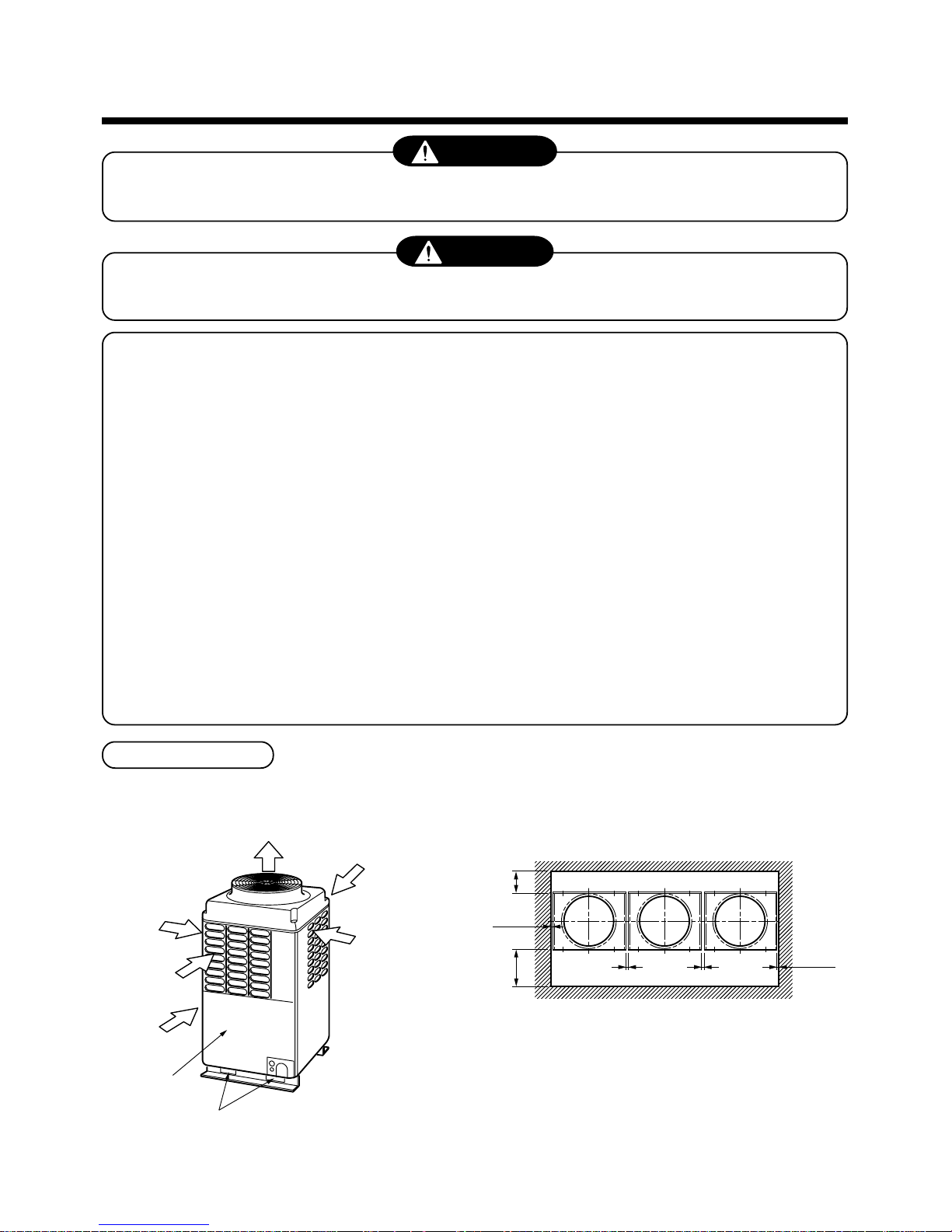
Installation space
Considering functions, reserve space necessary for installation work and servicing.
NOTES)
∗1 : If there is an obstacle at the upper side of the outdoor unit, reserve
a space by 2000mm or more to the top end of the outdoor unit.
∗2 : Arrange the height of obstacle around two outdoor units up to
below 800mm from the bottom end of the outdoor unit.
(Rear side)
(Front side)
(A case of 3 units are installed.)
500mm or more
500mm or more
10mm
or more
10mm
or more
20mm or more
20mm or more
Air outlet
Air inlet
Air inlet
Outdoor unit top view
Installation work/
servicing surface
Square hole for handling
Air inlet
Air inlet
5
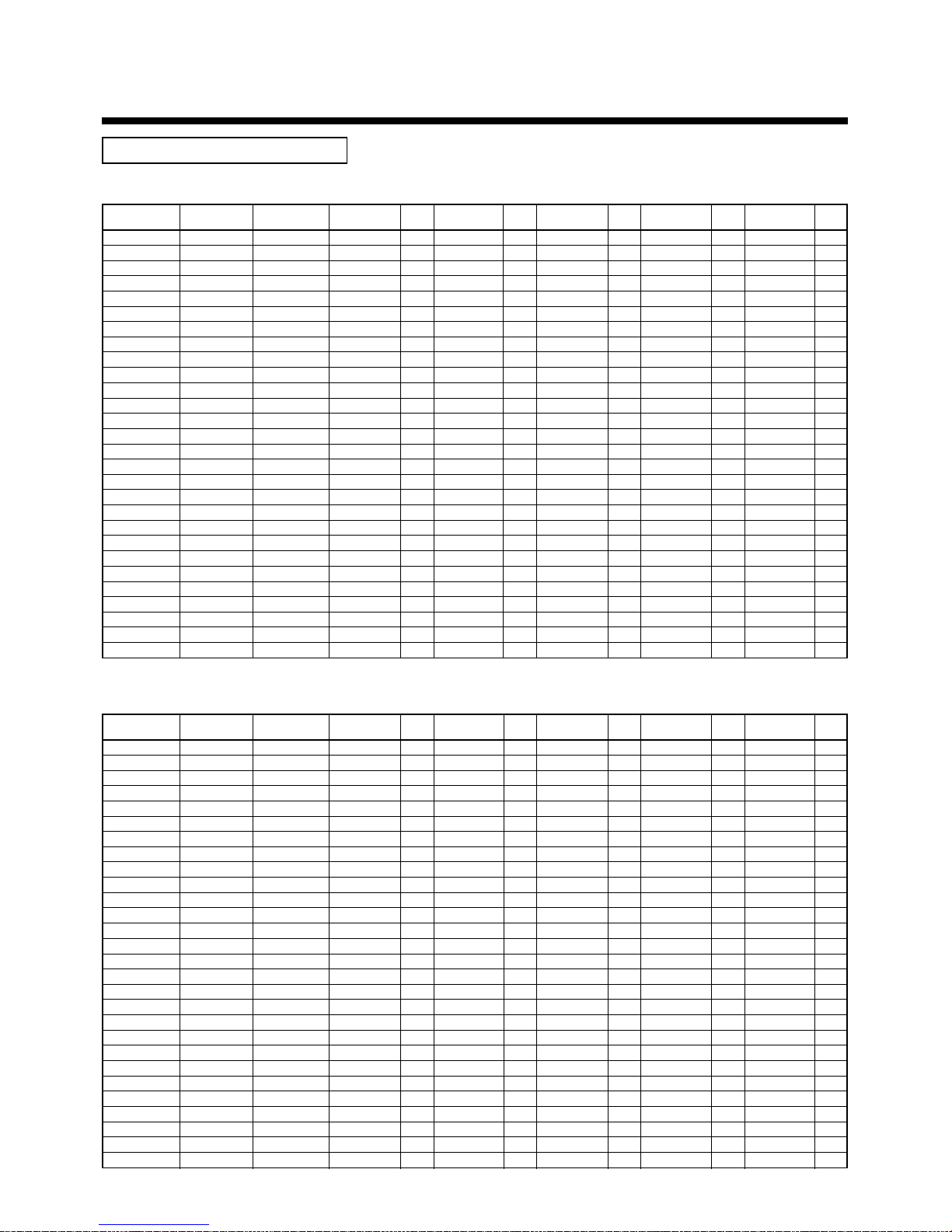
Combination of outdoor unit
Cooling Only Model
Heat-pump Model (50Hz)
HP
(Capacity code)
5HP ( 5)
6HP ( 6)
8HP ( 8)
10HP (10)
12HP (12)
14HP (14)
16HP (16)
18HP (18)
20HP (20)
22HP (22)
22HP (22)
24HP (24)
24HP (24)
26HP (26)
28HP (28)
30HP (30)
32HP (32)
32HP (32)
34HP (34)
34HP (34)
36HP (36)
36HP (36)
38HP (38)
40HP (40)
42HP (42)
44HP (44)
46HP (46)
48HP (46)
Model name
MMY-
MAP0501T8
MAP0601T8
MAP0801T8
MAP1001T8
MAP1201T8
AP1401T8
AP1601T8
AP1801T8
AP2001T8
AP2201T8
AP2211T8
AP2401T8
AP2411T8
AP2601T8
AP2801T8
AP3001T8
AP3201T8
AP3211T8
AP3401T8
AP3411T8
AP3601T8
AP3611T8
AP3801T8
AP4001T8
AP4201T8
AP4401T8
AP4601T8
AP4801T8
No. of
combined units
1
1
1
1
1
2
2
2
2
3
2
3
2
3
3
3
4
3
4
3
4
3
4
4
4
4
4
4
Inverter 5HP Used Inverter 6HP Used Inverter 8HP Used Inverter 10HP Used Inverter 12HP Used
MMY- Q’ty MMY- Q’ty MMY- Q’ty MMY- Q’ty MMY- Q’ty
MAP0501T8 1
MAP0601T8 1
MAP0801T8 1
MAP1001T8 1
MAP1201T8 1
MAP0601T8 1 MAP0801T8 1
MAP0801T8 2
MAP0801T8 1 MAP1001T8 1
MAP1001T8 2
MAP0601T8 1 MAP0801T8 2
MAP1001T8 1 MAP1201T8 1
MAP0801T8 3
MAP1201T8 2
MAP0801T8 2 MAP1001T8 1
MAP0801T8 1 MAP1001T8 2
MAP1001T8 3
MAP0801T8 4
MAP1001T8 2 MAP1201T8 1
MAP0801T8 3 MAP1001T8 1
MAP1001T8 1 MAP1201T8 2
MAP0801T8 2 MAP1001T8 2
MAP1201T8 3
MAP0801T8 1 MAP1001T8 3
MAP1001T8 4
MAP1001T8 3 MAP1201T8 1
MAP1001T8 2 MAP1201T8 2
MAP1001T8 1 MAP1201T8 3
MAP1201T8 4
HP
(Capacity code)
5HP ( 5)
6HP ( 6)
8HP ( 8)
10HP (10)
12HP (12)
14HP (14)
16HP (16)
18HP (18)
20HP (20)
22HP (22)
22HP (22)
24HP (24)
24HP (24)
26HP (26)
28HP (28)
30HP (30)
32HP (32)
32HP (32)
34HP (34)
34HP (34)
36HP (36)
36HP (36)
38HP (38)
40HP (40)
42HP (42)
44HP (44)
46HP (46)
48HP (46)
Model name
MMY-
MAP0501HT8
MAP0601HT8
MAP0801HT8
MAP1001HT8
MAP1201HT8
AP1401HT8
AP1601HT8
AP1801HT8
AP2001HT8
AP2201HT8
AP2211HT8
AP2401HT8
AP2411HT8
AP2601HT8
AP2801HT8
AP3001HT8
AP3201HT8
AP3211HT8
AP3401HT8
AP3411HT8
AP3601HT8
AP3611HT8
AP3801HT8
AP4001HT8
AP4201HT8
AP4401HT8
AP4601HT8
AP4801HT8
No. of
combined units
1
1
1
1
1
2
2
2
2
3
2
3
2
3
3
3
4
3
4
3
4
3
4
4
4
4
4
4
Inverter 5HP Used Inverter 6HP Used Inverter 8HP Used Inverter 10HP Used Inverter 12HP Used
MMY- Q’ty MMY- Q’ty MMY- Q’ty MMY- Q’ty MMY- Q’ty
MAP0501HT8 1
MAP0601HT8 1
MAP0801HT8 1
MAP1001HT8 1
MAP1201HT8 1
MAP0601HT8 1 MAP0801HT8 1
MAP0801HT8 2
MAP0801HT8 1 MAP1001HT8 1
MAP1001HT8 2
MAP0601HT8 1 MAP0801HT8 2
MAP1001HT8 1 MAP1201HT8 1
MAP0801HT8 3
MAP1201HT8 2
MAP0801HT8 2 MAP1001HT8 1
MAP0801HT8 1 MAP1001HT8 2
MAP1001HT8 3
MAP0801HT8 4
MAP1001HT8 2 MAP1201HT8 1
MAP0801HT8 3 MAP1001HT8 1
MAP1001HT8 1 MAP1201HT8 2
MAP0801HT8 2 MAP1001HT8 2
MAP1201HT8 3
MAP0801HT8 1 MAP1001HT8 3
MAP1001HT8 4
MAP1001HT8 3 MAP1201HT8 1
MAP1001HT8 2 MAP1201HT8 2
MAP1001HT8 1 MAP1201HT8 3
MAP1201HT8 4
2
SELECTION OF INSTALLATION PLACE
6
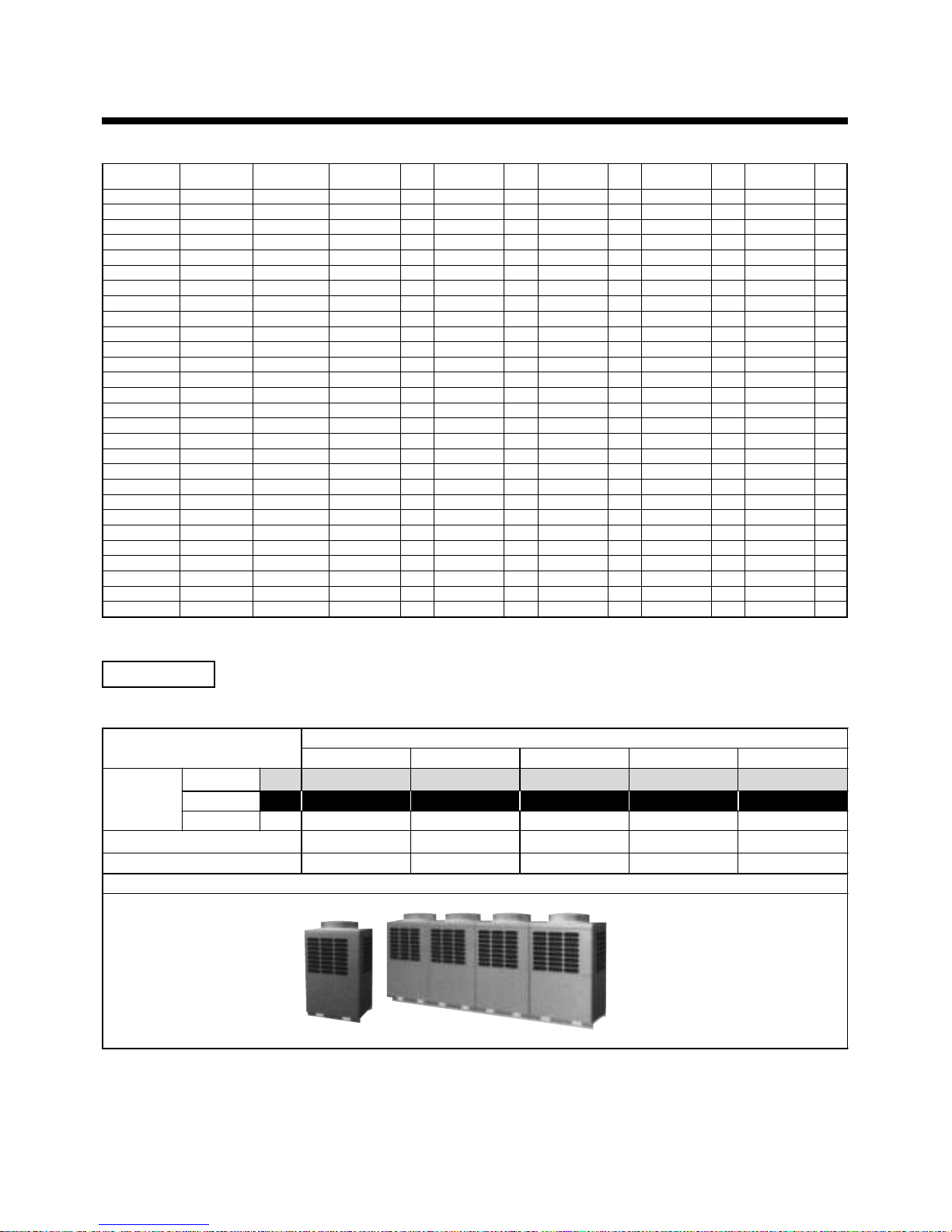
Heat-pump Model (60Hz)
HP
(Capacity code)
5HP ( 5)
6HP ( 6)
8HP ( 8)
10HP (10)
12HP (12)
14HP (14)
16HP (16)
18HP (18)
20HP (20)
22HP (22)
22HP (22)
24HP (24)
24HP (24)
26HP (26)
28HP (28)
30HP (30)
32HP (32)
32HP (32)
34HP (34)
34HP (34)
36HP (36)
36HP (36)
38HP (38)
40HP (40)
42HP (42)
44HP (44)
46HP (46)
48HP (46)
Model name
MMY-
MAP0501HT7
MAP0601HT7
MAP0801HT7
MAP1001HT7
MAP1201HT7
AP1401HT7
AP1601HT7
AP1801HT7
AP2001HT7
AP2201HT7
AP2211HT7
AP2401HT7
AP2411HT7
AP2601HT7
AP2801HT7
AP3001HT7
AP3201HT7
AP3211HT7
AP3401HT7
AP3411HT7
AP3601HT7
AP3611HT7
AP3801HT7
AP4001HT7
AP4201HT7
AP4401HT7
AP4601HT7
AP4801HT7
No. of
combined units
1
1
1
1
1
2
2
2
2
3
2
3
2
3
3
3
4
3
4
3
4
3
4
4
4
4
4
4
Inverter 5HP Used Inverter 6HP Used Inverter 8HP Used Inverter 10HP Used Inverter 12HP Used
MMY- Q’ty MMY- Q’ty MMY- Q’ty MMY- Q’ty MMY- Q’ty
MAP0501HT7 1
MAP0601HT7 1
MAP0801HT7 1
MAP1001HT7 1
MAP1201HT7 1
MAP0601HT7 1 MAP0801HT7 1
MAP0801HT7 2
MAP0801HT7 1 MAP1001HT7 1
MAP1001HT7 2
MAP0601HT7 1 MAP0801HT7 2
MAP1001HT7 1 MAP1201HT7 1
MAP0801HT7 3
MAP1201HT7 2
MAP0801HT7 2 MAP1001HT7 1
MAP0801HT7 1 MAP1001HT7 2
MAP1001HT7 3
MAP0801HT7 4
MAP1001HT7 2 MAP1201HT7 1
MAP0801HT7 3 MAP1001HT7 1
MAP1001HT7 1 MAP1201HT7 2
MAP0801HT7 2 MAP1001HT7 2
MAP1201HT7 3
MAP0801HT7 1 MAP1001HT7 3
MAP1001HT7 4
MAP1001HT7 3 MAP1201HT7 1
MAP1001HT7 2 MAP1201HT7 2
MAP1001HT7 1 MAP1201HT7 3
MAP1201HT7 4
Inverter unit
Corresponding HP
5 HP 6 HP 8 HP 10 HP 12 HP
Heat pump
MMY- MAP0501HT8 MAP0601HT8 MAP0801HT8 MAP1001H8 MAP1201HT8
Heat pump
MMY- MAP0501HT7 MAP0601HT7 MAP0801HT7 MAP1001HT7 MAP1201HT7
Model name
Cooling only
MMY- MAP0501T8 MAP0601T8 MAP0801T8 MAP1001T8 MAP1201T8
Cooling capacity (kW) 14.0 16.0 22.4 28.0 33.5
Heating capacity (kW) 16.0 18.0 25.0 31.5 37.5
Appearance
Equipments
1. Outdoor units
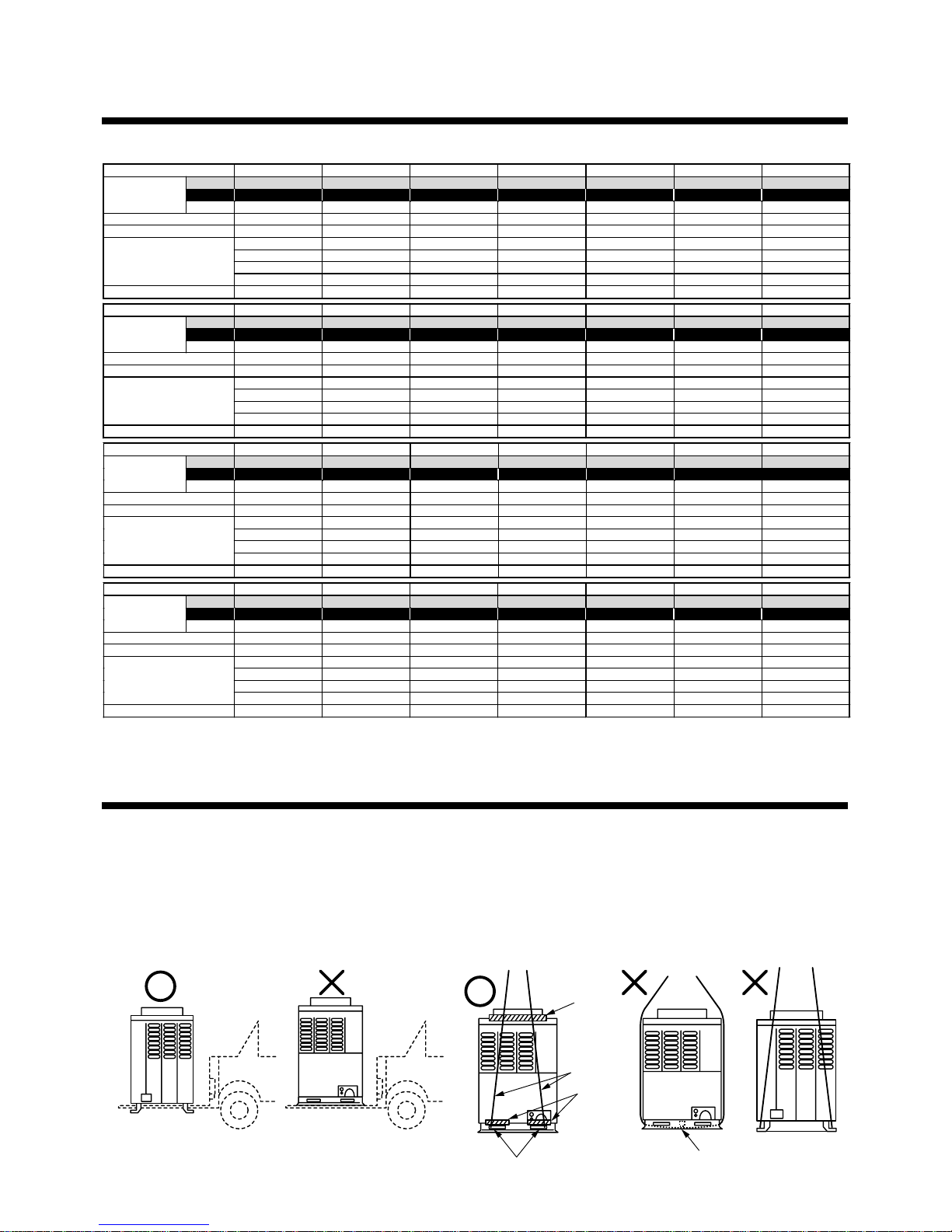
7
3
OUTDOOR UNIT CARRYING IN
Handle the outdoor unit in care with the following items.
1. When using a forklift, etc for loading/unloading in transportation, insert pawl of the forklift into the
square hole for handling as shown below.
2. When lifting up the unit, insert a rope sufficiently bearable to unit mass into the square hole for handling,
and cord the unit from four sides. (Apply a plaster to position where rope fits outdoor unit itself so that
flaw or deformation does not generate on the outer surface of the outdoor unit.)
(There provided the reinforcing plates on the side surfaces, so the rope cannot be passed.)
Corresponding HP 5 HP 6 HP 8 HP 10 HP 12 HP 14 HP 16 HP
MMY- MAP0501HT8 MAP0601HT8 MAP0801HT8 MAP1001HT8 MAP1201HT8 AP1401HT8 AP1601HT 8
MMY- MAP0501HT7 MAP0601HT7 MAP0801HT7 MAP1001HT7 MAP1201HT7 AP1401HT7 AP1601HT 7
Combined Model
MMY- MAP0501T8 MAP0601T8 MAP0801T8 MAP1001T8 MAP1201T8 AP1401T8 AP1601T8
Cooling capacity (kW) 14.0 16.0 22.4 28.0 33.5 38.4 45.0
Heating ca pa cit y (kW ) 16.0 18.0 25.0 31.5 37.5 43.0 50.0
5 HP 6 HP 8 HP 10 HP 12 HP 8 HP 8 H P
—————6 HP 8 HP
———————
Combined outdoor units
———————
No. of connectable indoor units 8 10 13 16 20 23 27
Corresponding HP 18 HP 20 HP 22 HP 22 HP 24 HP 24 HP 26 HP
MMY- AP1801HT 8 AP2001HT8 AP2201HT8 AP2211 HT8 AP2401HT8 AP2411HT8 AP2601 HT8
MMY- AP1801HT 7 AP2001HT7 AP2201HT7 AP2211 HT7 AP2401HT7 AP2411HT7 AP2601 HT7
Combined Model
MMY- AP1801T8 AP2001T8 AP2201T8 AP2211T8 AP2401T8 AP2411T8 AP2601T8
Cooling capacity (kW) 50.4 56.0 61.5 61.5 68.0 68.0 73.0
Heating ca pa cit y (kW ) 56.5 63.0 69.0 69.0 76.5 76.5 81.5
10 HP 10 HP 8 HP 12 HP 8 HP 12 HP 10 HP
8 HP 10 HP 8 HP 10 HP 8 HP 12 HP 8 HP
——6 HP — 8 HP — 8 HP
Combined outdoor units
———————
No. of connectable indoor units 30 33 37 37 40 40 43
Corresponding HP 28 HP 30 HP 32 HP 32 HP 34 HP 34 HP 36 HP
MMY- AP2801HT8 AP3001 HT8 AP3201HT8 AP3211HT8 AP3401HT 8 AP3411HT8 AP3601HT8
MMY- AP2801HT7 AP3001 HT7 AP3201HT7 AP3211HT7 AP3401HT 7 AP3411HT7 AP3601HT7
Combined Model
MMY-
AP2801T8 AP3001T8 AP3201T8 AP3211T8 AP3401T8 AP3411T8 AP3601T8
Cooling capacity (kW) 78.5 84. 0 90.0 90. 0 96.0 96. 0 101.0
Heat i n g c a pa c i t y (k W) 8 8.0 95.0 100.0 100.0 108.0 108.0 113.0
10 HP 10 HP 8 HP 12 HP 10 HP 12 HP 10 HP
10 HP 10 HP 8 HP 10 HP 8 HP 12 HP 10 HP
8 HP 10 HP 8 HP 10 HP 8 HP 10 HP 8 HP
Combined outdoor units
——8 HP — 8 HP — 8 HP
No. of connectable indoor units 47 48 48 48 48 48 48
Corresponding HP 36 HP 38 HP 40 HP 42 HP 44 HP 46 HP 48 HP
MMY- AP3611HT 8 AP3801HT8 AP4001HT8 AP4201 HT8 AP4401HT8 AP4601HT8 AP4801 HT8
MMY- AP3611HT 7 AP3801HT7 AP4001HT7 AP4201 HT7 AP4401HT7 AP4601HT7 AP4801 HT7
Combined Model
MMY-
AP3611T8 AP3801T8 AP4001T8 AP4201T8 AP4401T8 AP4601T8 AP4801T8
Cooling capacity (kW) 101.0 106.5 112.0 118.0 123.5 130.0 135.0
Heat i n g c a pa c i t y (k W) 113.0 119.5 126.5 132.0 138.0 145.0 150.0
12 HP 10 HP 10 HP 12 HP 12 HP 12 HP 12 HP
12 HP 10 HP 10 HP 10 HP 12 HP 12 HP 12 HP
12 HP 10 HP 10 HP 10 HP 10 HP 12 HP 12 HP
Combined outdoor units
— 8 HP 10 HP 10 HP 10 HP 10 HP 12 HP
No. of connectable indoor units 48 48 48 48 48 48 48
2. Outdoor units (Combination of outdoor units)
Plaster
Rope
Plaster
Square hole for handling
Reinforcing plate
Forklift Forklift
2
SELECTION OF INSTALLATION PLACE
8
4
INSTALLATION OF OUTDOOR UNIT
WARNING
Perform a specified installation work against a strong wind such as typhoon or earthquake.
If the air conditioner is imperfectly installed, an accident by falling or dropping may be caused.
Install the air conditioner certainly at a place bearable to weight.
If strength is insufficient, the unit may fall down resulting in human injury.
Drain water is discharged from the outdoor unit. (Especially in heating time)
Install the outdoor unit at a place where has good drainage.
For installation, be careful to the strength and the level of the foundation so that an abnormal
sound (Vibration, noise) does not generate.
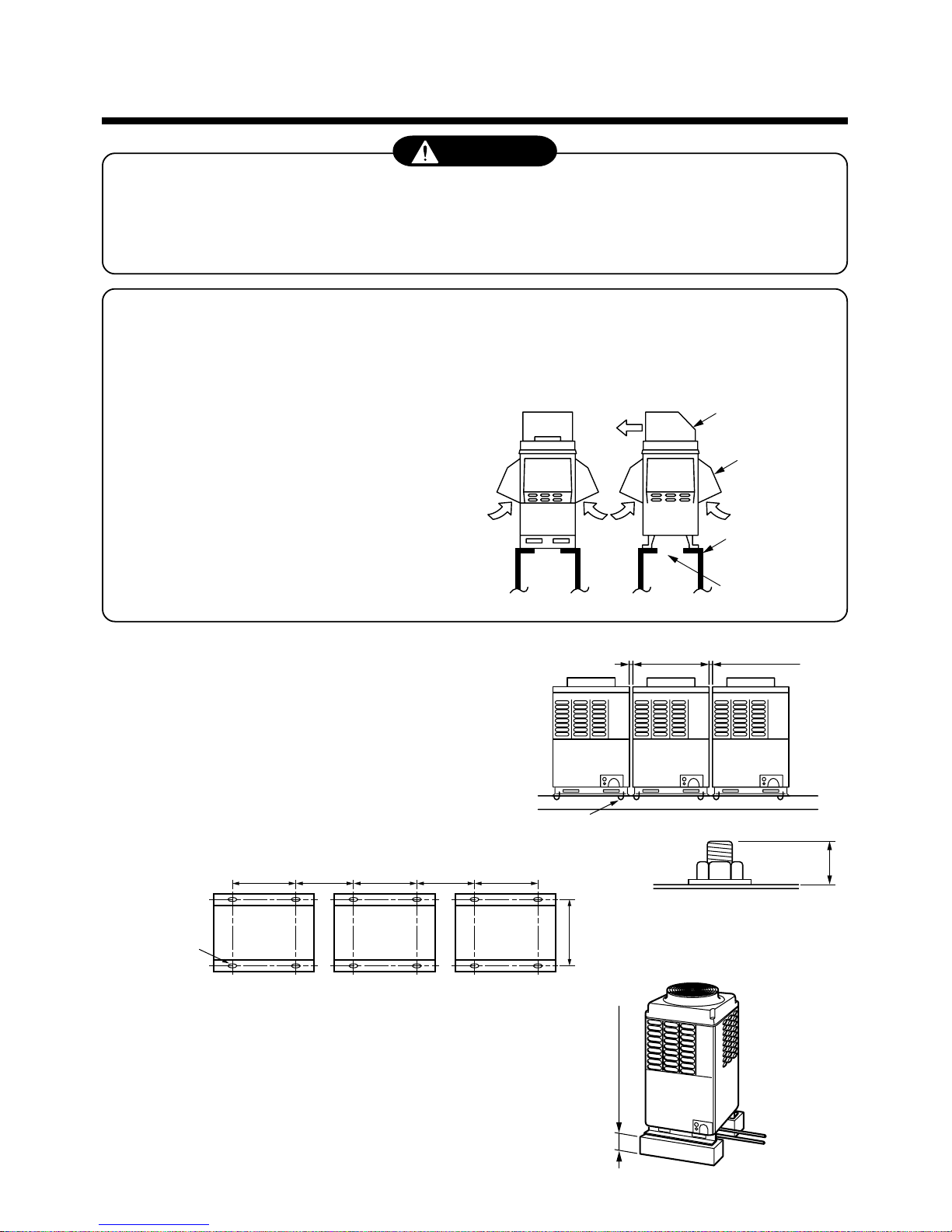
In the snowfall area, apply the following measures against
snowfall for the outdoor unit. (See the figure on the right.)
(Incomplete snowfall-proof measures causes a trouble.)
Place a higher stool under the unit, and mount the
snowfall-hoods to air inlet and air outlet so that
snows do not have influence.
(For the above works, please arrange at the field.)
1. To install the multiple outdoor units, arrange them with
20mm or more intervals.
Fix each outdoor unit with M12 anchor bolts at 4 positions.
Length by 20mm is appropriate for an anchor bolt.
• Anchor bolt pitch is as shown below:
2. When drawing out the refrigerant pipe from underside, set
height of the stool by 500mm or more.
20mm or more 20mm or more
M12 anchor bolt
4 positions/unit
20
700
310 or more
*
310 or more
700 700
755
Continuous hole
(15 x 20 long hole)
500mm or more
Snowfall-hood
for air outlet
Snowfall-hood
for air inlet
(4 faces)
Stool
Space for draining
9
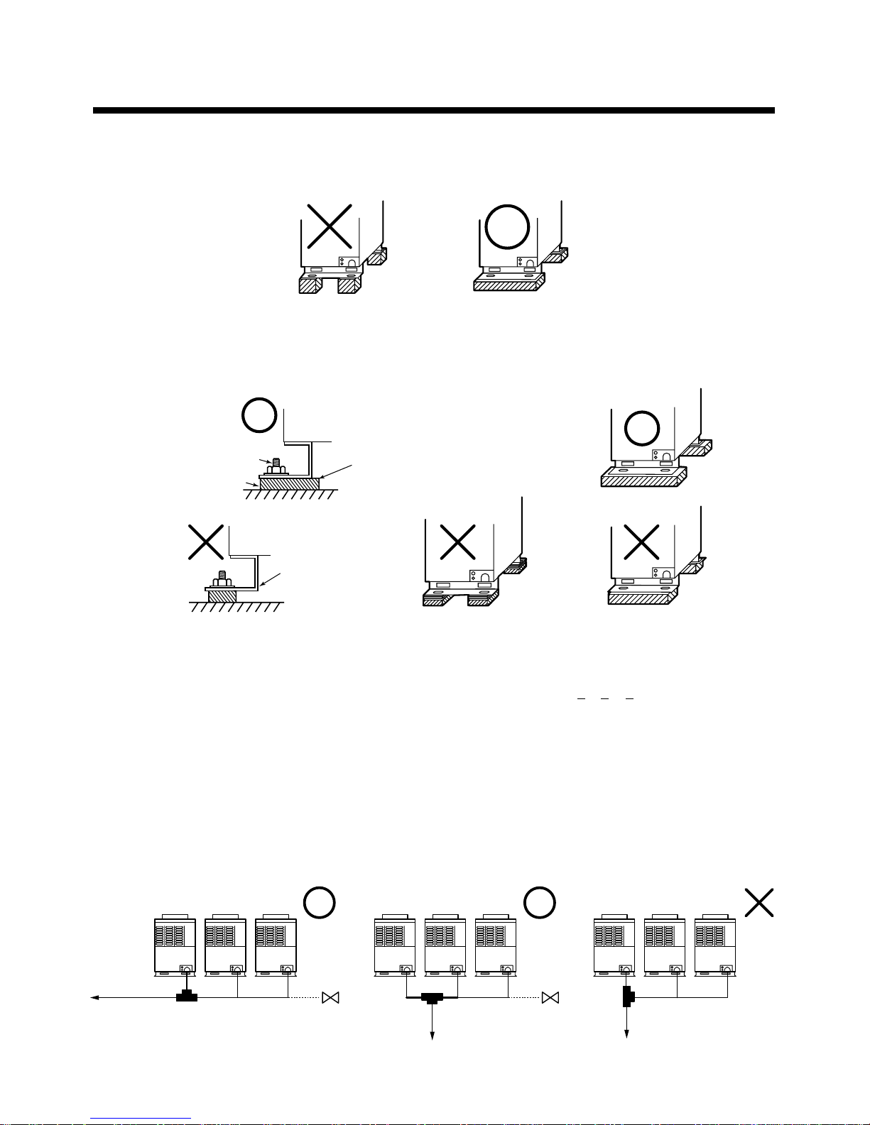
3. Do not use four stools to set the four corners.
4. Mount the vibration-proof rubber (vibration-proof block etc.) so that it catch whole the clamping leg.
5. Be careful to connecting arrangement of the header unit and the follower units.
Set the outdoor units in the order from one with large capacity. (A (Header unit)
> B > C > D)
6. Be careful to connecting arrangement of header unit and follower unit.
1) Be sure to use a header unit for the leading outdoor unit to be connected to the main pipe. (Figure 1)
2) However, as shown in the figure below, T-shape branching joint which is sold separately can be connected to
connect to the main pie within piping indicated with a bold line in the following figure. (Figure 2)
3) Be careful to direction of T-shape branching joint. (As shown in Figure 3, T-shape branching joint cannot be
attached so that refrigerant of the main pipe flows directly to the header unit.)
Install the vibration-proof rubber so that
bent part of the fixing leg is grounded.
Bent part of the fixing
leg is not grounded.
Anchor bolt
Vibration-proof rubber
Figure 1 Figure 2 Figure 3
Extension
valve
To indoor unit To indoor unit
Header
Follower Follower
Header
Follower Follower
Header
Follower Follower
Main pipe
To indoor unit
Main pipe Main pipe
Extension
valve
4
INSTALLATION OF OUTDOOR UNIT
10
5
REFRIGERANT PIPING
WARNING
If the refrigerant gas leaks during installation work, ventilate the room.
If the leaked refrigerant gas comes to contact with a fire, the noxious gas may generate.
After installation work, check that the refrigerant gas does not leak.
If the refrigerant gas leaks in the room and comes to contact with a fire such as fan heater, stove, or kitchen
range, the noxious gas may generate.
REQUIREMENT
For brazing, be sure to use nitrogen gas to avoid oxidation of pipe inside.
1. In a welding work for the refrigerant pipes, be sure to use the nitrogen gas in order to prevent oxidation inside
of the pipes; otherwise clogging of the refrigerating cycle due to oxidized scale generates.
2. Use clean and new pipes for the refrigerant pipes
and perform piping work so that water or dust is
not mixed.
3. Be sure to use a double spanner to loosen or
tighten the flare nut. If a single spanner is used, a
required tightening cannot be obtained. Tighten
the flare not with the specified torque.
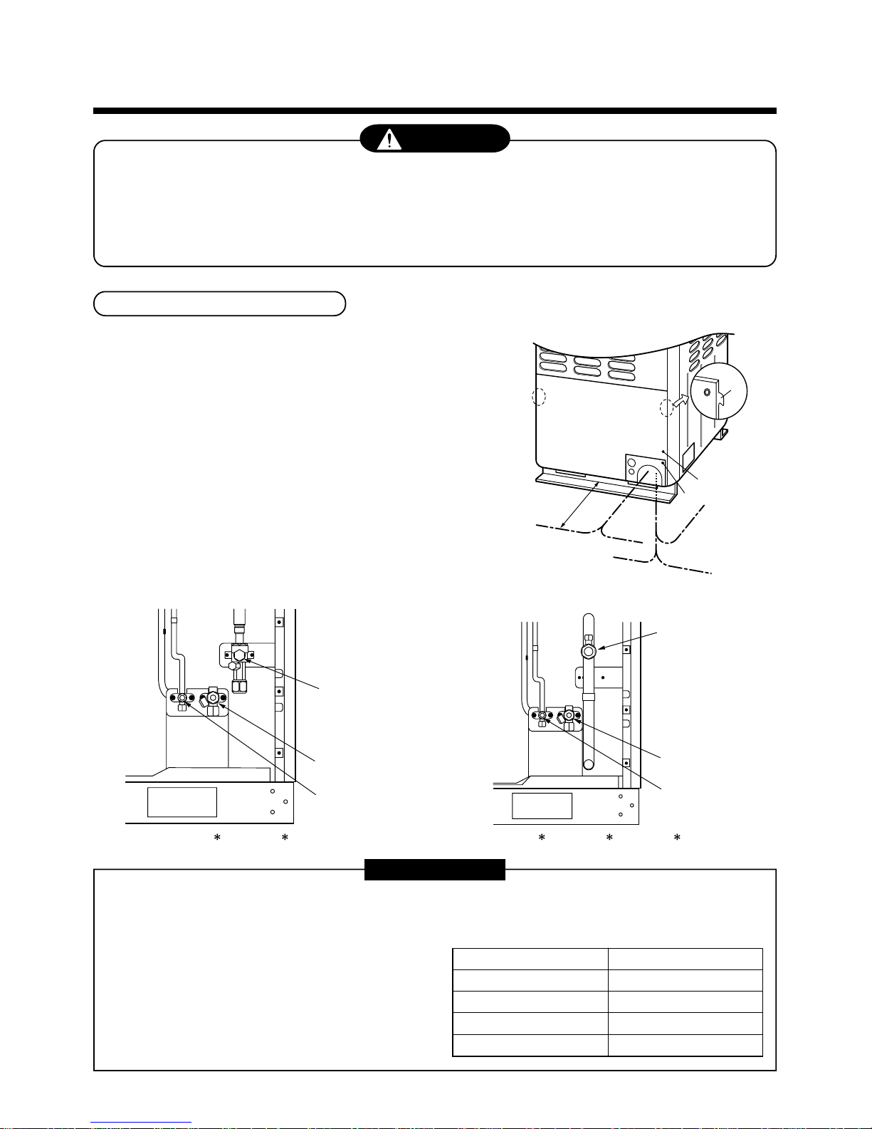
Connection of refrigerant pipe
1. The refrigerant pipe connecting section is set in the outdoor unit.
Remove the front panel and the piping/wiring panel. (M5: 9 pcs.)
• As shown in the right figure, the hooking hooks are attached at
right and left sides each on the front panel. Lift up and remove
the front panel.
2. Pipes can be drawn out forward and downward from the outdoor
unit.
3. When drawing out the pipe forward, draw out the pipe to outside
via piping/wiring panel, and keep space of 500mm or more from
the main pipe connecting the outdoor unit with the indoor unit,
considering service work, etc. (For replacing the compressor,
500mm or more space is required.)
4. When drawing out the pipe downward, remove the knockout of
the base plate of the outdoor unit, apply the pipe to outside of the
outdoor unit, and perform piping at right/left or rear side. Leading
pipe of the balancing should be within 4m.
Outer dia. of copper pipe
6.4 mm
9.5 mm
12.7 mm
15.9 mm
Tightening torque (N•m)
14 to 18 (1.4 to 1.8 kgf-m)
33 to 42 (3.3 to 4.2 kgf-m)
50 to 62 (5.0 to 6.2 kgf-m)
68 to 82 (6.8 to 8.2 kgf-m)
500mm
or more
Hook
Front panel
Piping/wiring panel
Drawing out
forward
(Left piping)
(Left piping)
(Right piping)
(Rear piping)
(Right
piping)
Drawing out
downward
Packed valve of
gas side
Ball valve of
gas side
Packed valve
of liquid side
Packed valve of
balance pipe
Packed valve of
liquid side
Packed valve of
balance pipe
(MMY-MAP0801
, MAP1001 , MAP1201 )(MMY-MAP0501 , MAP0601 )
11
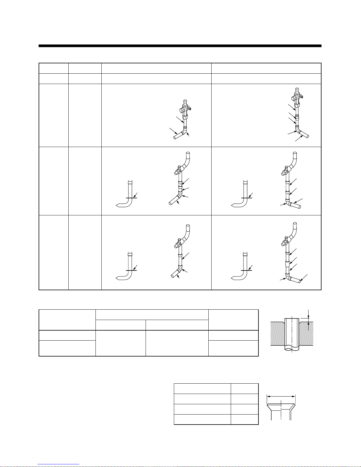
Pipe connecting method of valve at gas side (Example)
+0.0
–0.4
MMY-
MAP0501
∗∗
∗∗
∗
MAP0601
∗∗
∗∗
∗
MAP0801
∗∗
∗∗
∗
MAP1001
∗∗
∗∗
∗
MAP1201
∗∗
∗∗
∗
Pipe diameter
Ø15.9
Ø19.1
Ø22.2
Ø28.6
Draw-out forward
Connect Ø15.9 pipe with flaring.
Connect the attached pipe to the valve with
flaring, and then braze the elbow and pipe
procured locally.
Cut L-shape pipe at the straight
section, and then braze the elbow,
socket and pipe procured locally.
Cut L-shape pipe at the straight
section, and then braze the
elbow and pipe procured locally.
Draw-out downward
Connect Ø15.9 pipe with flaring.
Connect the attached pipe to the
valve with flaring, and
then braze the socket,
elbow and pipe
procured locally.
Cut L-shape pipe at the straight
section, and then braze the elbow,
socket and pipe procured
locally.
Cut L-shape pipe at the
straight section, and then
braze the elbow, socket
and pipe procured locally.
• Extruding margin of copper pipe with flare machining : B (Unit: mm)
Copper pipe outer dia.
9.5
12.7
15.9
Rigid (Clutch type)
R410A tool used Conventional tool used
0 to 0.5 1.0 to 1.5
Imperial (Wing nut)
1.5 to 2.0
2.0 to 2.5
• Extruding margin of copper pipe with flare tools :
A (Unit: mm)
Copper pipe outer dia.
9.5
12.7
15.9
A
13.2
16.6
19.7
B
A
5
REFRIGERANT PIPING
∗ When using the conventional flare tool, to
connect R410A pipes with flaring, make a
margin approx. 0.5mm longer than that of
R22 pipe so that the flare size matches
with the specified one. It is convenient to
use a copper pipe gauge for size
adjustment of the extruding margin.
Attached pipe
Pipe
Elbow
Attached pipe
Pipe
Pipe
Elbow
Socket
pipe
Elbow
L-shape
pipe
Attached
pipe
Pipe
Elbow
L-shape
pipe
Section to
be cut
Pipe
Pipe
Elbow
Socket
L-shape
pipe
Section to
be cut
Attached
pipe
Elbow
pipe
Pipe
L-shape
pipe
Section to
be cut
Section to
be cut
12
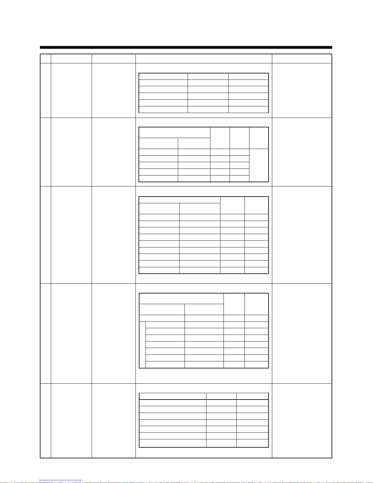
Table 1
Selection of pipe materials and size
• Selection of pipe material
Material: Phosphorus deoxidation seam-less pipe
• Capacity code of indoor and outdoor units
• For the indoor unit, the capacity code is decided at each capacity rank.
• The capacity codes of the outdoor units are decided at each capacity rank. The maximum No. of connectable
indoor unit and the total value of capacity codes of the indoor units are also decided.
Compared with the capacity code of the outdoor unit, the total value of capacity codes of the connectable indoor
units differs based on the height difference between the indoor units.
• When height difference between the indoor units is below 15m: Up to 135% of capacity code of the outdoor unit
• When height difference between the indoor units is over 15m: Up to 105% of capacity code of the outdoor unit
Table 2
* For combination of the outdoor units, refer to “Combination of outdoor units”.
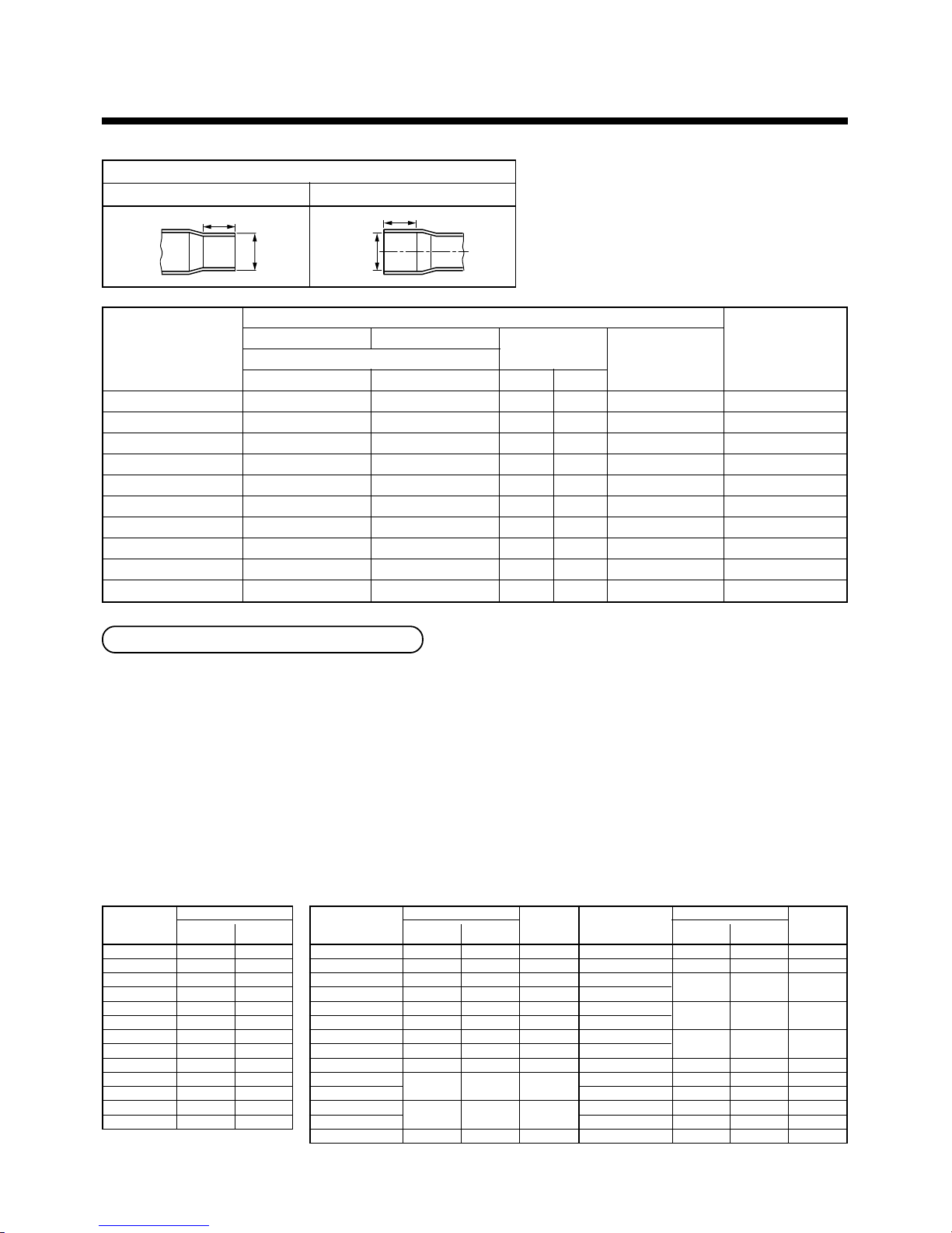
• Coupling size of brazed pipe
K
ØC
G
ØF
Connected section
External size Internal size
Indoor unit
capacity rank
007 type
009 type
012 type
015 type
018 type
024 type
027 type
030 type
036 type
048 type
056 type
072 type
096 type
Capacity code
Equivalent Equivalent
to HP to capacity
0.8 2.2
1 2.8
1.25 3.6
1.7 4.5
2 5.6
2.5 7.1
38
3.2 9
4 11.2
514
616
8 22.4
10 28
Outdoor unit
model name
MMY-MAP0501
∗
MMY-MAP0601
∗
MMY-MAP0801
∗
MMY-MAP1001
∗
MMY-MAP1201
∗
MMY-AP1401
∗
MMY-AP1601
∗
MMY-AP1801
∗
MMY-AP2001
∗
MMY-AP2201
∗
MMY-AP2211
∗
MMY-AP2401
∗
MMY-AP2411
∗
MMY-AP2601
∗
Capacity code
Equivalent Equivalent
to HP to capacity
514
616
8 22.4
10 28
12 33.5
14 38.4
16 45
18 50.4
20 56
22 61.5
24 68
26 73
No. of
indoor
units
8
10
13
16
20
23
27
30
33
37
40
43
Outdoor unit
model name
MMY-AP2801
∗
MMY-AP3001
∗
MMY-AP3201
∗
MMY-AP3211
∗
MMY-AP3401
∗
MMY-AP3411
∗
MMY-AP3601
∗
MMY-AP3611
∗
MMY-AP3801
∗
MMY-AP4001
∗
MMY-AP4201
∗
MMY-AP4401
∗
MMY-AP4601
∗
MMY-AP4801
∗
Capacity code
Equivalent Equivalent
to HP to capacity
28 78.5
30 84
32 90
34 96
36 101
38 106.5
40 112
42 118
44 123.5
46 130
48 135
No. of
indoor
units
47
48
48
48
48
48
48
48
48
48
48
Standard outer dia. of
connected copper pipe
6.35
9.52
12.70
15.88
19.05
22.22
28.58
34.92
38.10
41.28
Connected section
External size Internal siz
Standard outer dia. (Allowable difference)
CF
6.35 (±0.03) 6.45 ( )
9.52 (±0.03) 9.62 ( )
12.70 (±0.03) 12.81 ( )
15.88 (±0.03) 16.00 ( )
19.05 (±0.03) 19.19 ( )
22.22 (±0.03) 22.36 ( )
28.58 (±0.04) 28.75 ( )
34.90 (±0.04) 35.11 ( )
38.10 (±0.05) 38.31 ( )
41.28 (±0.05) 41.50 ( )
Min. depth
of insertion
KG
76
87
98
98
11 10
11 10
13 12
14 13
15 14
15 14
Oval value
0.06 or less
0.08 or less
0.10 or less
0.13 or less
0.15 or less
0.16 or less
0.20 or less
0.25 or less
0.27 or less
0.28 or less
Min. thickness
of coupling
0.50
0.60
0.70
0.80
0.80
0.82
1.00
1.20
1.26
1.35
+0.04
–0.02
+0.04
–0.02
+0.04
–0.02
+0.04
–0.02
+0.03
–0.03
+0.03
–0.03
+0.06
–0.02
+0.04
–0.04
+0.08
–0.02
+0.08
–0.02
(Unit: mm)
13
No.
Piping parts
Outdoor unit
↓
T-shape
branching joint
Between T-shape
branching joints
T-shape joint of
header unit
↓
1st branching
section
Branching section
↓
Branching section
Branching section
↓
Indoor unit
Name
Outdoor unit
connecting pipe
Main connecting
piping between of
outdoor units
Balance pipe
Main piping
Branching pipe
Indoor unit
connecting pipe
Selection of pipe size
1)Connecting pipe outdoor unit
Model
MMY-MAP0501H
MMY-MAP0601H
MMY-MAP0801H
MMY-MAP1001H
MMY-MAP1201H
Gas side
Ø15.9
Ø19.1
Ø22.2
Ø22.2
Ø28.6
Liquid side
Ø9.5
Ø9.5
Ø12.7
Ø12.7
Ø12.7
2)Pipe size for connecting piping between outdoor units
Total capacity codes of outdoor
units at downstream side
Equivalent Equivalent
to capacity to HP
Below 38.4 Below 14
38.4 to below 61.5 14 to below 22
61.5 to below 73.0 22 to below 26
73.0 to below 96.0 26 to below 36
Above 101.0 Above 36
Gas
side
Ø28.6
Ø28.6
Ø34.9
Ø34.9
Ø41.3
Liquid
side
Ø12.7
Ø15.9
Ø15.9
Ø19.1
Ø22.2
Balance
pipe
Ø9.5
3)Size of main piping
Total capacity codes of all outdoor units
Equivalent Equivalent
to capacity to HP
Below 16.0 Below 6
16.0 to below 22.4 6 to below 8
22.4 to below 33.5 8 to below 12
33.5 to below 38.4 12 to below 14
38.4 to below 61.5 14 to below 22
61.5 to below 73.0 22 to below 26
73.0 to below 101.0 26 to below 36
101.0 to below 118.0 36 to below 46
Above 118.0 Above 46
Gas side
Ø15.9
Ø19.1
Ø22.2
Ø28.6
Ø28.6
Ø34.9
Ø34.9
Ø41.3
Ø41.3∗
Liquid side
Ø9.5
Ø9.5
Ø12.7
Ø12.7
Ø15.9
Ø15.9
Ø19.1
Ø22.2
Ø22.2
∗Max. equivalent length of main pipe is below 70m.
4)Pipe size between branching sections
Total capacity codes of indoor units
at downstream side
Equivalent Equivalent
to capacity to HP
Below 7.5 Below 2.8
7.5 to below 18.0 2.8 to below 6.4
18.0 to below 34.0 6.4 to below 12.2
34.0 to below 56.5 12.2 to below 20.2
∗
56.5 to below 70.5 20.2 to below 25.2
1
70.5 to below 98.5 25.2 to below 35.2
98.5 to below 118.5 35.2 to below 42.2
Above 118.5 Above 42.2
Gas side
Ø12.7
Ø15.9
Ø22.2
Ø28.6
Ø34.9
Ø34.9
Ø41.3
Ø41.3
Liquid side
Ø9.5
Ø9.5
Ø12.7
Ø15.9
Ø15.9
Ø19.1
Ø22.2
Ø22.2
5)Connecting pipe size of indoor unit
Capacity rank
007 to 012 type (15m or less)
007 to 012 type (15m or more)
015 to 018 type
024 to 048 type
056 type
072 type
096 type
Gas side
Ø9.5
Ø12.7
Ø12.7
Ø15.9
Ø15.9
Ø19.1
Ø22.2
Liquid side
Ø6.4
Ø6.4
Ø6.4
Ø9.5
Ø9.5
Ø12.7
Ø12.7
Remarks
Same to connecting pipe
size of outdoor unit
Pipe size differs based on
total capacity code value of
outdoor units at
downstream side.
(See Table 2.)
Pipe size differs based on
capacity code of outdoor
unit.
(See Table 2.)
Pipe size differs based on
total capacity code value of
indoor units at downstream
side.
If the total value exceeds
the capacity code of the
outdoor unit, apply capacity
code of the outdoor unit.
(See Table 1.2.)
∗1: If exceeding the main pipe size, decide the size same to
main pipe size.
5
REFRIGERANT PIPING
14
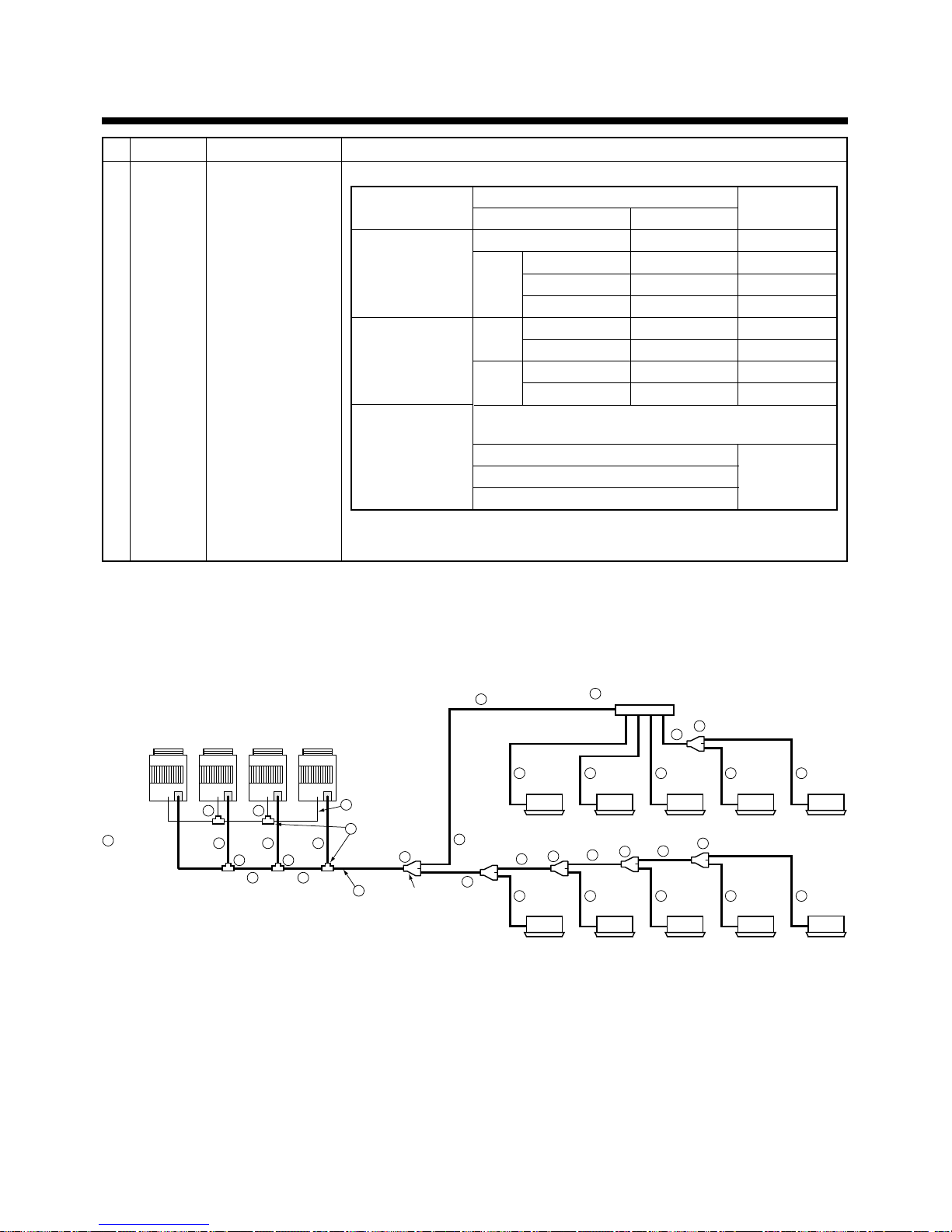
1
1 1 1
22
4
5 5 5
4
4
4
4
4
5 5
5 5 5 5 5
7
6
66
6 6
6
6
6
6
6
6
6
Outdoor
unit
Balance pipe
T-shape
branching joint
Outdoor unit
connecting
piping
Main connecting
piping between
outdoor units
Branching pipe
Branching header
1st branching
section
Indoor unit connecting pipe
Y-shape
branching
joint
Indoor unit
connecting pipe
Follower
unit 2
Follower
unit 3
Follower
unit 1
Header unit
Indoor unit
Indoor unit
3
Main piping
∗1: If exceeding the main pipe size, decide the size same to main pipe size.
∗2: Up to total 6.0 of Max. capacity codes is connectable to one line after branching of header.
No.
Piping parts
Branching
section
Name
Y-shape branching joint
Branching header
T-shape branching joint
Selection of pipe size
6)Selection of branching section
Y-shape branching joint
Branching header ∗2
T-shape branching joint
(For link of outdoor units)
Total capacity code of indoor units
Equivalent to capacity Equivalent to HP
Below 18.0 Below 6.4
18.0 to below 40.0 6.4 to below 14.2
*1 40.0 to below 70.5 14.2 to below 25.2
Above 70.5 Above 25.2
For 4
Below 40.0 Below 14.2
branches
40.0 to below 70.5 14.2 to below 25.2
For 8
Below 40.0 Below 14.2
branches
40.0 to below 70.5 14.2 to below 25.2
• Balance pipe (Corresponding dia. Ø9.5) × 1
• Pipe at liquid side (Ø9.5 to Ø22.1) × 1
• Pipe at gas side (Ø15.9 to Ø41.3) × 1
Model name
RBM-BY53E
RBM-BY103E
RBM-BY203E
RBM-BY303E
RBM-HY1043E
RBM-HY2043E
RBM-HY1083E
RBM-HY2083E
RBM-BT13E
The following 3 types of T-shape branching joint pipes are made to one set.
Arrange the required quantities and combine at the local site.
15
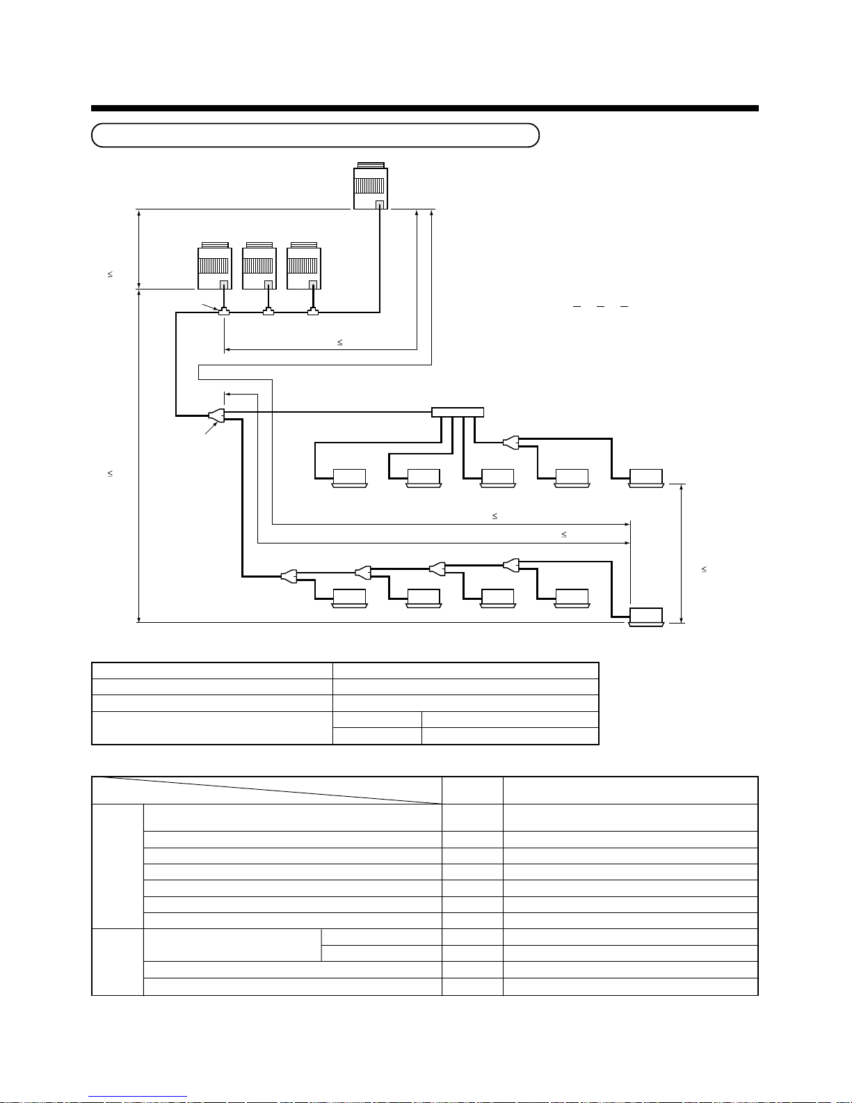
Allowable length of refrigerant pipe and height difference
Outdoor unit
T-shape branching
joint
La
LA
A
D
BC
LB
Lb Lc
Main
piping
L1
1st branching
section
Height
difference
between
outdoor
units
H3
5 m
Height
difference
between
outdoor
units
H1
50 m
Follower
unit 3
outdoor unit
connecting
pipe
Follower
unit 1
Follower
unit 2
Header
unit
Main connecting piping between outdoor units
Length corresponded to farthest piping
between outdoor units LO
25 m
Branching pipe L2
Connecting piping of indoor unit L7
bcdea
ghi jf
L4
L5
L6
L3
Branching
header
Indoor unit
Indoor unit
Equivalent length corresponded to farthest piping L
175 m
Equivalent length corresponded to farthest piping after 1st branching Li
65 m
Y-joint
Height difference
between indoor
units
H2
30 m
Ld
(a)
(d)
(b) (c)
• Cautions concerned with installation/
construction
1) The leading outdoor unit connected with the
indoor inter-unit pipe is made “A (Header unit)”.
2) Set the units in order of the outdoor capacity.
(A (Header unit)
> B > C > D)
3) For the combination of the outdoor units, refer to
“Combination of outdoor unit” list.
• Restriction to the system
• Allowable length/height difference of the refrigerant pipe
Pipe
length
Height
difference
Allowable
value
300m
175m
85m
65m
25m
10m
30m
50m
40m (*2)
30m
5m
Pipe section
LA + LB + La + Lb + Lc + Ld + L1 + L2 + L3 + L4
+ L5 + L6 + L7 + a + b + c + d + e + f + g + h + i + j
LA + LB + Ld + L1 + L3 + L4 + L5 + L6 + j
L1
L3 + L4 + L5 + L6 + j
LA + LB + Ld (LA + Lb, LA + LB + Lc)
Ld (La, Lb, Lc)
a, b, c, d, e, f, g, h, i, j
——
——
——
——
Total extended pipe length
(Liquid pipe/real length)
Farthest equivalent piping length L (∗1)
Max. equivalent length of main pipe (∗3)
Farthest equivalent piping length from 1st branch Li (∗1)
Farthest equivalent piping length between outdoor units LO (∗1)
Max. equivalent length of outdoor unit connecting pipe
Max. real length of outdoor unit connecting pipe
Height difference between
Outdoor at upper side
indoor unit and outdoor unit H1
Outdoor at lower side
Height difference between indoor units H2
Height difference between outdoor units H3
Max. No. of combined outdoor units
Max. capacity of combined outdoor units
Max. No. of connected indoor units
Max. capacity of connected indoor units
(Differs by height difference between indoor units)
4 units
48HP
48 units
H2 < 15m 135% of capacity of outdoor unit
15m < H2 < 30m 105% of capacity of outdoor unit
∗1 : Farthest outdoor unit: (d), farthest indoor unit: (j) from 1st branch
∗2 : If the height difference (H2) between indoor units exceeds 3m, set below 30m.
∗∗
∗∗
∗3 :If Max. capacity of the combined outdoor units exceeds 46HP, Max. equivalent length is up to 70m.
5
REFRIGERANT PIPING
16
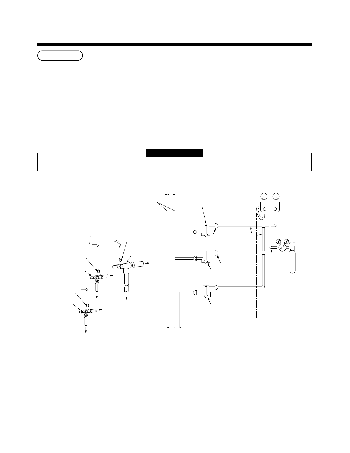
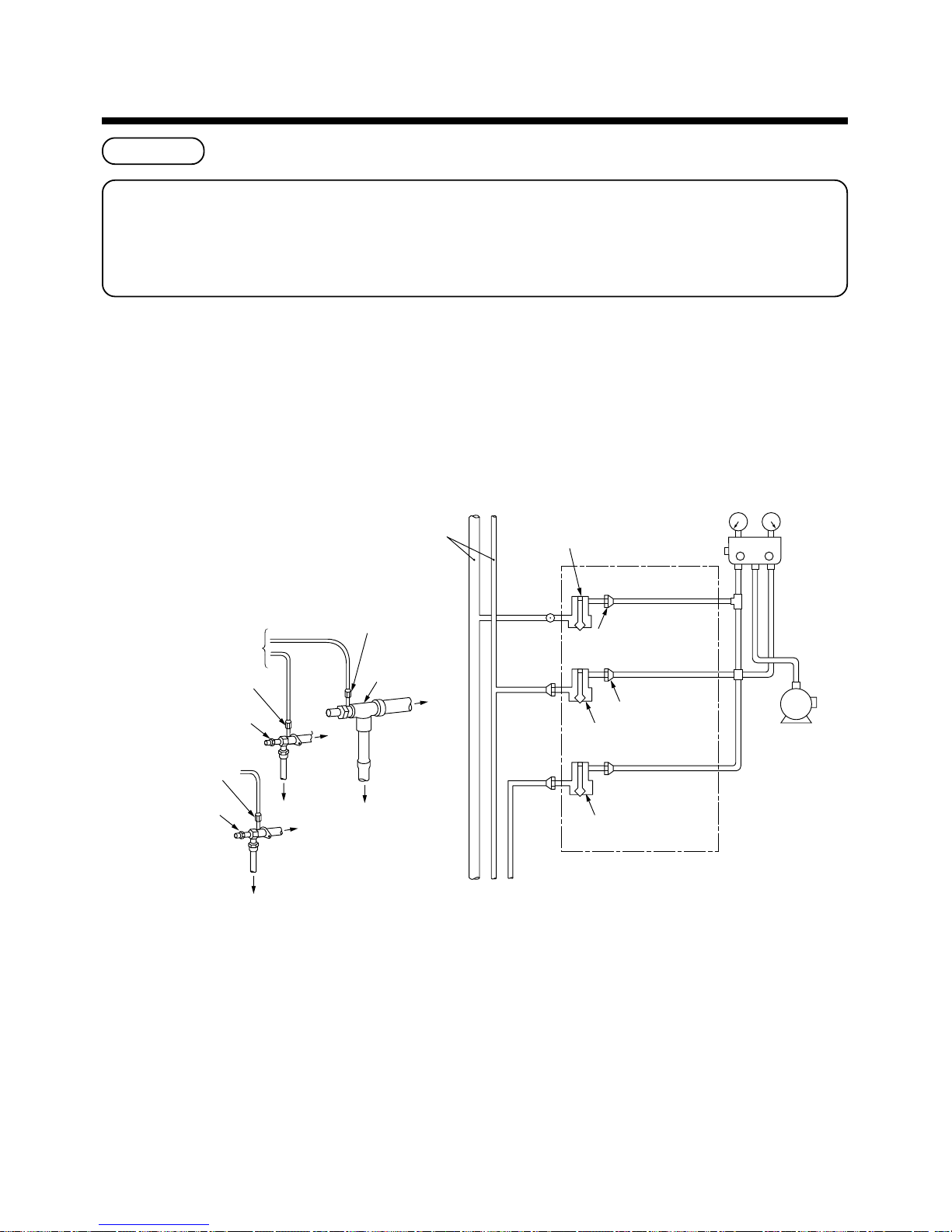
Airtight test
After the refrigerant piping has finished, execute an airtight test. For an airtight test, connect a nitrogen gas bomb as
shown in the figure below, and apply pressure.
• Be sure to apply pressure from the service ports of the packed valves (or ball valves) at liquid side, gas side, and
balance pipe side.
• An airtight test can be only performed to the service ports at liquid side, gas side, and balance side of the header
unit.
• Close fully valves at liquid side, gas side, and balance side. As there is possibility that nitrogen gas enters in the
refrigerant cycle, re-tighten the valve rods before applying pressure. (Re-tightening of the valve rods are
unnecessary for valves at gas side of MMY-MAP0501∗ and MAP0601∗ because they are ball valves.)
• For each refrigerant line, apply pressure gradually with steps at liquid side, gas side, and balance side.
Be sure to apply pressure to liquid side, gas side, and balance side.
REQUIREMENT
Never use “Oxygen”, “Flammable gas” and “Noxious gas” in an airtight test.
STEP 1 : Apply pressure 0.3MPa (3.0kg/cm2G) for 3 minutes or more.
Available to detect a gross leakage
STEP 2 : Apply pressure 1.5MPa (15kg/cm2G) for 3 minutes or more.
STEP 3 : Apply pressure 3.73MPa (38kg/cm2G) for approx. 24 hours. Available to detect slow leakage
• Check pressure down.
No pressure down: Accepted Pressure down: Check the leaked position.
However, if there is difference of ambient temp. between when pressure has been applied and when
24 hours passed, pressure changes by approx. 0.01MPa (0.1kg/cm²G) per 1°C. Correct the pressure.
Leaked position check
When a pressure-down is detected in STEP 1, STEP 2, or STEP 3, check the leakage at the connecting points.
Check leakage with hearing sense, feeler, foaming agent, etc, and perform re-brazing or re-tightening of flare if
leakage is detected.
VLV
H
Connected to indoor unit
Main pipe
Packed valve fully closed
(gas side)
Header outdoor unit
Lowpressure
gauge
Highpressure
gauge
Gauge
manifold
Brazed
Service
port
Service port
Ø6.4
Copper pipe
Ø6.4
Copper
pipe
Fully
closed
Fully
closed
Reducing
valve
Nitrogen
gas
Packed valve fully closed
(liquid side)
Packed valve fully closed
(balance)
Connected to other follower outdoor units
Detailed drawing of packed valve
To gauge manifold
Gas-side
service port
Gas-side
packed valve
To outdoor
unit
To outdoor unit
To
outdoor
unit
Liquid-side
packed valve
Liquid-side
service port
Balance
packed valve
Balance
service port
Piping at site
Piping
at site
Piping
at site
17
Air purge
For the air purge at installation time (Discharge of air in connecting pipes), use “Vacuum pump method” from
viewpoint of protection of earth environment.
• For protection of earth environment, do not discharge the flon gas in the air.
• Using a vacuum pump, eliminate the remained air (nitrogen gas, etc.) in the unit. If gas remains, an absence
of faculties may be caused.
After the airtight test, discharge nitrogen gas. Then connect the gauge manifold to the service ports at liquid, gas,
and balance sides, and connect the vacuum pump as shown in the following figure. Be sure to perform vacuuming
for liquid, gas and balance sides.
• Be sure to perform vacuuming from both liquid and gas sides.
• Be sure to use a vacuum pump with counter-flow preventive function so that oil in the pump does not back up in
the pipe of the air conditioner while the pump stops. (If oil in the vacuum pump enters in the air conditioner with
R410A refrigerant, a trouble is caused in the refrigerating cycle.)
• Use a vacuum pump having a high vacuuming degree (below -755mmHg) and a large exhaust gas amount (over
40L/minute).
• Perform vacuuming for 2 or 3 hours though time differs due to pipe length. In this time, check all packed valves at
liquid, gas, and balance sides are fully closed.
• If vacuuming valve amount is not decreased to below -755mmHg even after vacuuming for 2 hours or more,
continue vacuuming for 1 hour or more. If -755mmHg or less cannot be obtained by 3 hours or more vacuuming,
check the leaked position.
• When vacuuming valve reached to -755mmHg or less after vacuuming for 2 hours or more, close valves VL and
VH of the gauge manifold fully, stop the vacuum pump, leave it as it is for 1 hour, and then check the vacuuming
degree does not change. If it changed, there may be a leaked position. Check the leaked position.
• After the above procedure of vacuuming has finished, exchange the vacuum pump with a refrigerant cylinder and
advance to the additional charging of refrigerant.
P
VLV
H
Connected to indoor unit
Main pipe
Packed valve fully closed
(gas side)
Header outdoor unit
Lowpressure
gauge
Highpressure
gauge
Gauge
manifold
Brazed
Service
port
Service port
Fully
closed
Fully
closed
Packed valve fully closed
(liquid side)
Packed valve fully closed
(Balance)
Connected to other follower outdoor units
Detailed drawing of packed valve
To gauge manifold
Gas-side service port
Gas-side
packed valve
or ball valve
To outdoor
unit
To outdoor unit
To
outdoor
unit
Liquid-side
packed valve
Liquid-side
service port
Balance
packed valve
Balance
service port
Piping at site
Piping
at site
Piping
at site
Vacuum pump
5
REFRIGERANT PIPING
18
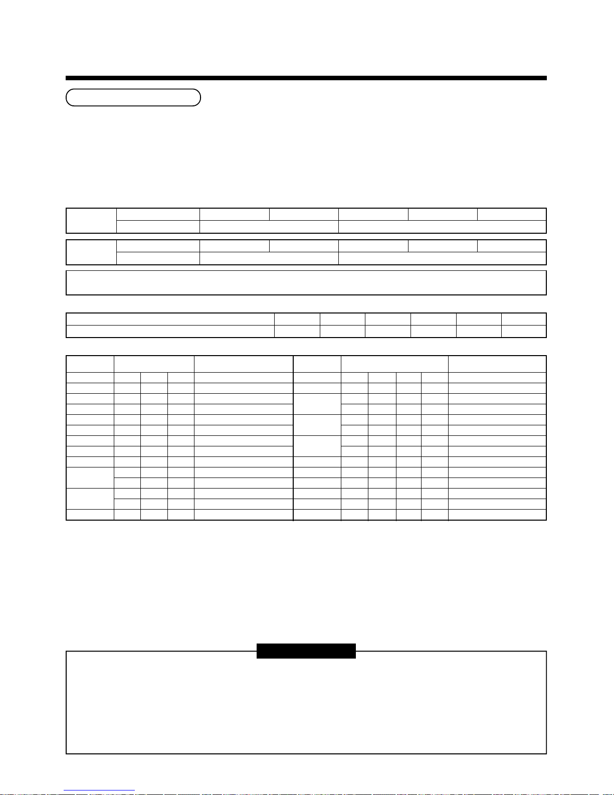
Addition of refrigerant
After vacuuming work, exchange the vacuum pump with the refrigerant bomb and then start the additional charging
work of refrigerant.
Calculation of additional refrigerant charge amount
Refrigerant charge amount at shipment from the factory does not include the refrigerant for pipe at the local site.
For refrigerant to be charged in pipe at the local site, calculate the amount and charge it additionally.
NOTE) If the additional refrigerant amount indicates minus as the result of calculation, use the air conditioner
without addition of refrigerant.
Additional refrigerant = Real length × Additional refrigerant charge + Corrective amount of refrigerant
charge amount at local site of liquid pipe amount per 1m liquid pipe (Table 1) combined horse power (Table 2)
Table 1
Charging of refrigerant
• Keeping valve of the outdoor unit closed, be sure to charge the liquid refrigerant into service port at liquid side.
• If the specified amount of refrigerant cannot be charged, open fully valves of outdoor unit at liquid and gas sides,
operate the air conditioner in COOL mode under condition that valve at gas side is a little returned to close side
(MAP0801∗, MA1001∗, MAP1201∗ only), and then charge refrigerant into service port at gas side. In this time,
choke the refrigerant slightly by operating valve of the bomb to charge liquid refrigerant. The liquid refrigerant may
be charged suddenly, therefore be sure to charge refrigerant gradually.
• When refrigerant leaks and refrigerant shortage occurs in the system, recover the refrigerant in the system and
recharge refrigerant newly up to the correct level.
REQUIREMENT
<Entry of refrigerant charge amount>
• Fill the additional refrigerant record column of the wiring diagram indication plate with the additional refrigerant
amount at installation work, total refrigerant amount and the name of the service man who charged refrigerant
at installation time.
• The total refrigerant amount means the total value of the refrigerant amount at shipment and the additional
refrigerant amount at installation time. The refrigerant amount at the shipment is one described on the “Unit
nameplate”.
Table 2
Liquid pipe dia. (mm)
Additional refrigerant amount/1m liquid pipe (kg/m)
6.4 9.5 12.7 15.9 19.1 22.2
0.025 0.055 0.105 0.160 0.250 0.350
Combined HP
(HP)
5
6
8
10
12
14
16
18
20
22
24
26
Combined outdoor units
(HP)
5
6
8
10
12
86
88
10 8
10 10
12 10
886
12 12
888
10 8 8
C (Corrective amount of refrigerant)
(kg)
0.0
0.0
1.5
2.5
3.5
0.0
0.0
0.0
3.0
5.0
0.0
7.0
–4.0
–4.0
Combined HP
(HP)
28
30
32
34
36
38
40
42
44
46
48
Combined outdoor units
(HP)
10 10 8
10 10 10
12 10 10
8888
12 12 10
10888
12 12 12
10 10 8 8
10 10 10 8
10 10 10 10
12 10 10 10
12 12 10 10
12 12 12 10
12 12 12 12
C (Corrective amount of refrigerant)
(kg)
–2.0
0.0
1.0
–6.0
3.0
–6.0
4.0
–6.0
–6.0
–5.0
–4.0
–2.0
0.0
2.0
Heat pump
model
MMY-MAP0501HT
∗∗
∗∗
∗ MMY-MAP0601HT
∗∗
∗∗
∗ MMY-MAP0801HT
∗∗
∗∗
∗ MMY-MAP1001HT
∗∗
∗∗
∗ MMY-MAP1201HT
∗∗
∗∗
∗
8.5 12.5
Outdoor unit Model
Charging amount (kg)
Cooling only
model
MMY-MAP0501T8 MMY-MAP0601T8 MMY-MAP0801T8 MMY-MAP1001T8 MMY-MAP1201T8
8.0 11.0
Outdoor unit Model
Charging amount (kg)
19
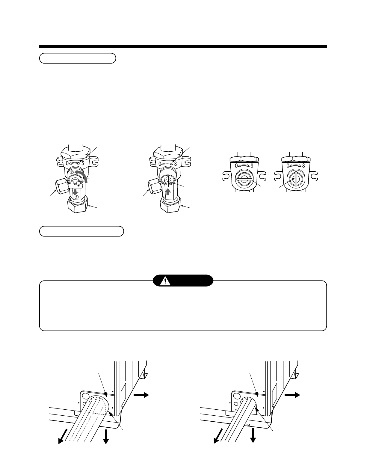
Full opening of valve
• Open valve of the outdoor unit fully.
• Using 4mm-hexagonal wrench, open fully the valve rods at liquid and balance sides.
• Using a spanner, etc, open fully the valve rod of packed valve (MMY-MAP0801∗, MAP1001∗, MAP1201∗) at gas
side.
• Using the pinchers, open fully the handle of the ball valve (MMY-MAP0501∗, MAP0601∗) at gas side.
Be careful that handling of ball valve differs from that of packed valve.
How to open the ball valve at gas side
Valve unit
Valve unit
Charge port
Charge port
Handle
Pull out the handle and
using cutting pliers, etc.
turn it counterclockwise
by 90˚. (Open fully)
Flare nut
Flare nut
Push in handle.
Closed completely
Handle
Handle position
Opened fully
Heat insulation for pipe
• Apply heat insulation of pipe separately at liquid, gas, and balance sides.
• Be sure to use thermal insulator with heat-resisting temp. 120°C or more.
5
REFRIGERANT PIPING
CAUTION
• After piping connection work has finished, cover the opening of the piping/wiring panel with the piping cover, or
fill silicon or putty in space of the pipes.
• In case of drawing-out the pipes downward or sideward direction, also close the openings of the base plate
and the side plate.
• Under the opened condition, a trouble may be caused due to entering of water or dust.
In case of using pipe cover In case of using no pipe cover
Piping/wiring panel
Drawing-out sideward
Drawing-out downward
Drawing-out
frontward
Fill silicon or putty in
periphery of the pipes.
Piping/wiring panel
Drawing-out sideward
Drawing-out downward
Drawing-out
frontward
Close the opening
with pipe cover.
20
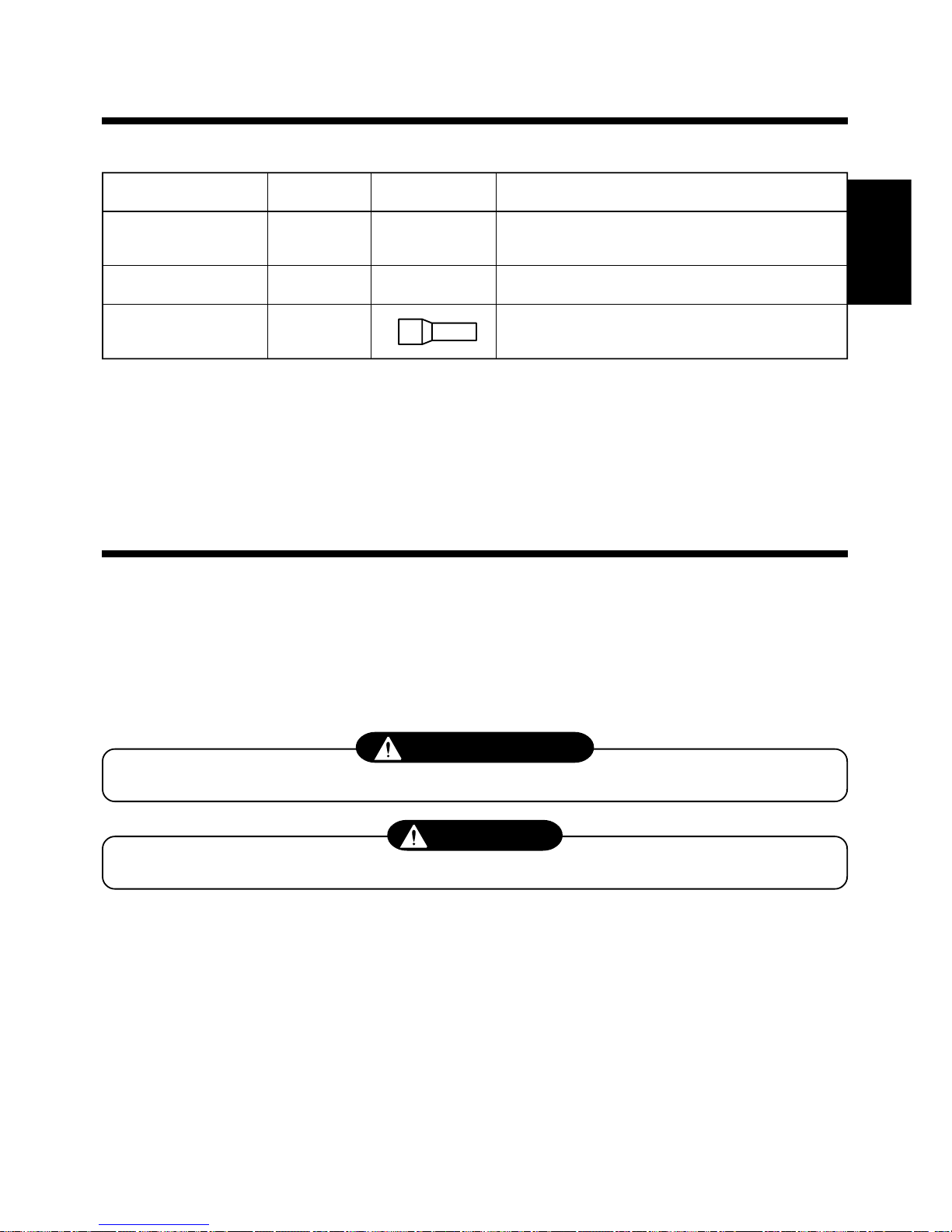
PIECES ACCESSOIRES
r Pièces accessoires
Nom de la pièce
Manuel d’installation
Manuel du propriétaire
Tuyaux fournis
Quantité
2
1
1 de chaque
Forme
VOLUME-1
VOLUME-2
—
Usage
(S’assurer de le remettre aux clients.)
(S’assurer de le remettre aux clients.)
Tuyaux de raccordement côté gaz
(sauf MMY-MAP0501∗)
MESURES DE SECURITE
• Veuillez lire attentivement ces “Mesures de sécurité” avant l’installation pour installer correctement
le climatiseur.
• Les points importants relatifs à la sécurité sont décrits dans les “Mesures de sécurité”.
Assurez-vous de les conserver. Pour les indications et leur signification, voir la description ciaprès.
n Explication des indications
AVERTISSEMENT
Indique un risque de mort ou de blessures corporelles graves en cas de manipulation incorrecte.
ATTENTION
Indique un risque de blessure (∗1) ou de seul dommage matériel (∗2) en cas d’installation incorrecte.
∗1 :Le terme “blessure” représente un choc, une brûlure ou une électrocution ne requérant pas l’hospitalisation ou un
séjour de longue durée à l’hôpital.
∗2 :Le terme “dommage matériel” représente un dommage aggravé d’un bien ou la rupture du matériel.
• L’installation terminée, faites un essai de fonctionnement pour vous assurer de l’absence de
problèmes et expliquez les méthodes d’utilisation et d’entretien aux clients à partir du Manuel du
propriétaire.
Veuillez demander aux clients de conserver ce Manuel d’installation avec le Manuel du propriétaire.
FRANCAIS

21
AVERTISSEMENT
Demandez à un revendeur ou à un professionnel d’installer le climatiseur.
Si vous l’installez vous-même, vous risquez un incendie, une électrocution ou une fuite d’eau.
A l’aide des outils ou du matériel de tuyauterie exclusivement dédiés au R410A, installez le
climatiseur en toute sécurité conformément à ce Manuel d’installation.
La pression du réfrigérant HFC (R410A) est d’environ 1.6 fois plus élevée que celle du réfrigérant précédent.
En cas de non-utilisation du matériel de tuyauterie exclusif ou d’imperfection de l’installation, vous risquez une
rupture ou une blessure ainsi qu’une fuite d’eau, une électrocution ou un incendie.
Prenez des mesures afin que le réfrigérant ne dépasse pas la concentration limite même s’il fuit
lors de l’installation du climatiseur dans une petite pièce.
Contactez votre revendeur pour les mesures permettant de ne pas dépasser la limite de concentration.
Si le réfrigérant fuit et dépasse la limite de concentration, vous risquez un accident par manque d’oxygène.
Installez le climatiseur dans un endroit qui puisse supporter son poids.
Si l’endroit n’est pas assez résistant, l’unité peut tomber et provoquer des blessures.
Effectuez l’installation spécifiée contre les vents forts, comme le typhon, ou les tremblements de
terre.
Si le climatiseur est mal installé, il peut tomber et provoquer un accident.
Si le gaz réfrigérant fuit durant l’installation, aérez la pièce.
Si le gaz réfrigérant qui a fui entre en contact avec le feu, un gaz nocif peut se dégager.
Après l’installation, assurez-vous que le gaz réfrigérant ne fuit pas.
Si le gaz réfrigérant fuit dans la pièce et entre en contact avec le feu, comme un radiateur soufflant, un poêle ou une
cuisinière, un gaz nocif peut se dégager.
Ne récupérez jamais le réfrigérant dans l’unité extérieure.
Assurez-vous d’utiliser un dispositif de récupération de réfrigérant pour récupérer ce dernier lors d’une réinstallation
ou d’une réparation.
La récupération de réfrigérant dans l’unité extérieure risque de provoquer un accident grave, comme une rupture ou
une blessure corporelle.
Un électricien qualifié doit s’occuper de l’installation électrique conformément à la réglementation
de la société électrique locale et au Manuel d’installation. Assurez-vous d’utiliser le circuit
exclusif.
Vous risquez un incendie ou une électrocution en cas de manque de puissance du circuit d’alimentation ou
d’installation incomplète.
Pour le câblage, utilisez les câbles spécifiés et raccordez-les en toute sécurité de sorte que la
pression extérieure exercée sur les câbles ne se transmette pas à la section de raccordement des
bornes.
Si le raccordement ou la fixation des câbles sont incomplets, vous risquez un incendie, etc.
Assurez-vous de raccorder le fil de terre.
Ne raccordez pas le fil de terre aux tuyaux de gaz, aux tuyaux d’eau, aux paratonnerre ou au fil de terre du
téléphone.
Si la mise à la terre est incomplète, vous risquez une électrocution.
ATTENTION
N’installez pas le climatiseur dans un endroit où le gaz inflammable risque de fuir.
Si le gaz fuit et s’accumule autour de l’unité, vous risquez un incendie.
Assurez-vous de monter un interrupteur de dispersion à la terre ; autrement, vous risquez une
électrocution.
A l’aide d’une clé dynamométrique, serrez l’écrou évasé selon la méthode spécifiée.
Si l’écrou évasé est trop serré, il se cassera et vous risquez une fuite de réfrigérant après un certain temps.
MESURES DE SECURITE

22
1
INSTALLATION DU CLIMATISEUR UTILISANT LE NOUVEAU REFRIGERANT
Ce climatiseur utilise le nouveau réfrigérant HFC (R410A), qui ne détruit pas la couche d’ozone.
• Le réfrigérant R410A peut être affecté par les impuretés, comme l’eau, la membrane oxydante ou l’huile car sa
pression est environ 1.6 fois plus élevée que celle du réfrigérant précédent. Outre l’utilisation du nouveau réfrigérant,
l’huile réfrigérante a elle aussi été remplacée. Par conséquent, durant l’installation, prenez soin que l’eau, la poussière,
le réfrigérant précédent ou l’huile réfrigérante n’entrent pas dans le circuit de réfrigération du climatiseur utilisant le
nouveau réfrigérant.
• Pour éviter que le réfrigérant et l’huile réfrigérante ne se mélangent, la taille du port de remplissage de l’unité principale
ou la section de raccordement des outils d’installation sont différentes de celles qui sont utilisées pour le réfrigérant
précédent. En conséquence, les outils exclusifs sont requis pour le nouveau réfrigérant (R410A), comme indiqué ciaprès.
• Pour raccorder les tuyaux, utilisez du matériel de tuyauterie neuf et propre de sorte que l’eau ou la poussière n’entre
pas dans les tuyaux.
Outils requis et précautions de manipulation
Pour effectuer l’installation, il est nécessaire de préparer les outils et pièces comme indiqué ci-après.
Les outils et pièces neufs indiqués ci-après doivent être limités à l’utilisation exclusive.
Explication des symboles
l
: de fabrication récente (Il est nécessaire d’utiliser les outils exclusivement dédiés au R410A, séparément des outils
dédiés au R22 ou au R407C.)
¡ :l’outil précédent est disponible.
Outils utilisés
Collecteur manométrique
Tuyau de remplissage
Bouteille de remplissage
Détecteur de fuite de gaz
Pompe à vide
Pompe à vide avec adaptateur
de prévention du refoulement
Outil d’évasement
Cintreuse
Dispositif de récupération de
réfrigérant
Clé dynamométrique
Coupe-tube
Bouteille de réfrigérant
Soudeuse/Bouteille d’azote
Equilibrage du remplissage de
réfrigérant
Usage
Pompage à vide ou
remplissage du réfrigérant et
vérification du fonctionnement
Remplissage du réfrigérant
Vérification de fuite de gaz
Déshumidification sous vide
Déshumidification sous vide
Evasement des tuyaux
Cintrage des tuyaux
Récupération du réfrigérant
Serrage de l’écrou évasé
Coupe des tuyaux
Remplissage du réfrigérant
Soudage des tuyaux
Remplissage du réfrigérant
Emploi correct des outils/pièces
l
De fabrication récente, exclusivement dédié au
R410A
l
De fabrication récente, exclusivement dédié au
R410A
Inutilisable
(Utiliser l’équilibrage du remplissage de réfrigérant.)
l
De fabrication récente
Utilisable en cas de montage d’un adaptateur de
prévention du refoulement.
¡
: R22 (article existant)
¡
: Utilisable en réglant la taille
¡
: R22 (article existant)
l
Exclusivement dédié au R410A
l
Ø12.7mm – Exclusivement dédié à Ø15.9 mm
¡
: R22 (article existant)
l
Exclusivement dédié au R410A
ID : identité du réfrigérant
¡
: R22 (article existant)
¡
: R22 (article existant)
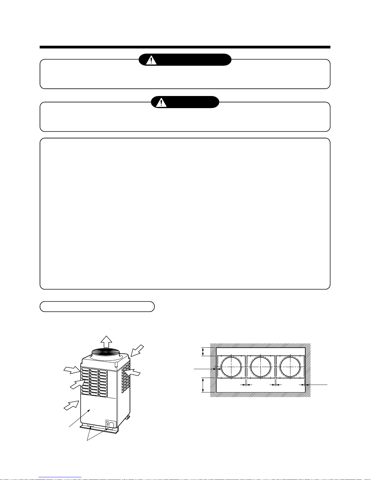
23
2
SELECTION DU LIEU D’INSTALLATION
AVERTISSEMENT
Installez solidement le climatiseur dans un endroit suffisamment résistant pour supporter son poids.
Si l’endroit n’est pas assez résistant, l’unité peut tomber et provoquer des blessures.
ATTENTION
N’installez pas le climatiseur dans un endroit où le gaz inflammable risque de fuir.
Si le gaz fuit et s’accumule autour de l’unité, vous risquez un incendie.
Sur autorisation du client, installez le climatiseur dans un endroit remplissant les conditions
suivantes.
• Un endroit où il puisse être installé à l’horizontale.
• Un endroit desservi par un espace suffisant pour effectuer l’entretien ou le contrôle en toute sécurité.
• Un endroit qui ne pose aucun problème, même en cas d’écoulement de l’eau d’évacuation.
Appliquez un isolant électrique entre la section métallique de la construction et celle du
climatiseur conformément à la réglementation locale.
Evitez les endroits suivants.
• Un endroit riche en sel (bord de mer) ou en gaz sulfureux (source chaude).
(Dans ce type d’endroit, un entretien particulier est requis.)
• Un endroit exposé à l’huile (dont l’huile machine), à la vapeur, aux fumées d’huile ou aux gaz corrosifs.
• Un endroit où un dispositif générateur de haute fréquence (inverseur, générateur non utilitaire, appareil médical ou
équipement de communication) est installé. (Un effet néfaste de ce type de dispositif peut engendrer un
dysfonctionnement du climatiseur, une erreur de commande ou des parasites.)
• Un endroit où l’air refoulé par l’unité extérieure souffle sur les fenêtres du voisinage.
• Un endroit où le bruit de fonctionnement de l’unité extérieure se transmet.
(En particulier à la limite du voisinage, installez le climatiseur en tenant compte du bruit.)
• Un endroit ne supportant pas le poids de l’unité.
• Un endroit mal ventilé.
Espace requis pour l’installation
En tenant compte des fonctions, laissez l’espace nécessaire à l’installation et à l’entretien.
(Arrière)
(Avant)
(Installation d’un groupe de 3 unités)
500 mm ou plus
500 mm ou plus
10 mm
ou plus
10 mm
ou plus
20mm ou plus
20mm ou plus
Sortie de l’air
Entrée de l’air
Entrée de l’air
Vue de dessus de l’unité extérieure
Surface d’installation/
d’entretien
Trou carré de manutention
Entrée de l’air
Entrée de l’air
REMARQUES)
*1 : Laissez un espace de 2 000 mm ou plus entre un obstacle et le
haut de l’unité.
*2 : Laissez un espace maximum de 800 mm entre un obstacle
entourant deux unités extérieures et le bas des unités extérieures.
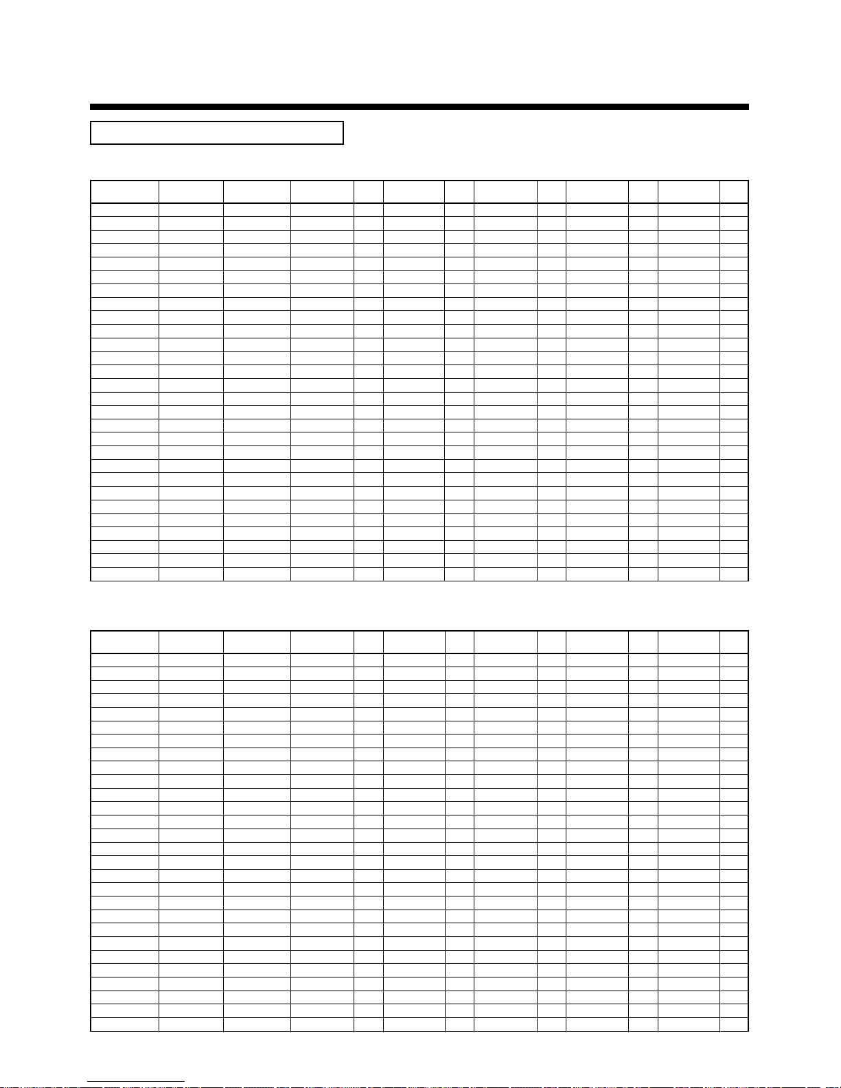
24
Combinaison d’unités extérieures
Modèle à froid seul
CV
(code de puissance)
5HP ( 5)
6HP ( 6)
8HP ( 8)
10HP (10)
12HP (12)
14HP (14)
16HP (16)
18HP (18)
20HP (20)
22HP (22)
22HP (22)
24HP (24)
24HP (24)
26HP (26)
28HP (28)
30HP (30)
32HP (32)
32HP (32)
34HP (34)
34HP (34)
36HP (36)
36HP (36)
38HP (38)
40HP (40)
42HP (42)
44HP (44)
46HP (46)
48HP (46)
Nom du modèle
MMY-
MAP0501T8
MAP0601T8
MAP0801T8
MAP1001T8
MAP1201T8
AP1401T8
AP1601T8
AP1801T8
AP2001T8
AP2201T8
AP2211T8
AP2401T8
AP2411T8
AP2601T8
AP2801T8
AP3001T8
AP3201T8
AP3211T8
AP3401T8
AP3411T8
AP3601T8
AP3611T8
AP3801T8
AP4001T8
AP4201T8
AP4401T8
AP4601T8
AP4801T8
Nombre d’unités
combinées
1
1
1
1
1
2
2
2
2
3
2
3
2
3
3
3
4
3
4
3
4
3
4
4
4
4
4
4
Inverseur 5 CV
Quantité
Inverseur 6 CV
Quantité
Inverseur 8 CV
Quantité
Inverseur 10 CV
Quantité
Inverseur 12 CV
Quantité
MMY-
utilisée
MMY-
utilisée
MMY-
utilisée
MMY-
utilisée
MMY-
utilisée
MAP0501T8 1
MAP0601T8 1
MAP0801T8 1
MAP1001T8 1
MAP1201T8 1
MAP0601T8 1 MAP0801T8 1
MAP0801T8 2
MAP0801T8 1 MAP1001T8 1
MAP1001T8 2
MAP0601T8 1 MAP0801T8 2
MAP1001T8 1 MAP1201T8 1
MAP0801T8 3
MAP1201T8 2
MAP0801T8 2 MAP1001T8 1
MAP0801T8 1 MAP1001T8 2
MAP1001T8 3
MAP0801T8 4
MAP1001T8 2 MAP1201T8 1
MAP0801T8 3 MAP1001T8 1
MAP1001T8 1 MAP1201T8 2
MAP0801T8 2 MAP1001T8 2
MAP1201T8 3
MAP0801T8 1 MAP1001T8 3
MAP1001T8 4
MAP1001T8 3 MAP1201T8 1
MAP1001T8 2 MAP1201T8 2
MAP1001T8 1 MAP1201T8 3
MAP1201T8 4
CV
(code de puissance)
5HP ( 5)
6HP ( 6)
8HP ( 8)
10HP (10)
12HP (12)
14HP (14)
16HP (16)
18HP (18)
20HP (20)
22HP (22)
22HP (22)
24HP (24)
24HP (24)
26HP (26)
28HP (28)
30HP (30)
32HP (32)
32HP (32)
34HP (34)
34HP (34)
36HP (36)
36HP (36)
38HP (38)
40HP (40)
42HP (42)
44HP (44)
46HP (46)
48HP (46)
Nom du modèle
MMY-
MAP0501HT8
MAP0601HT8
MAP0801HT8
MAP1001HT8
MAP1201HT8
AP1401HT8
AP1601HT8
AP1801HT8
AP2001HT8
AP2201HT8
AP2211HT8
AP2401HT8
AP2411HT8
AP2601HT8
AP2801HT8
AP3001HT8
AP3201HT8
AP3211HT8
AP3401HT8
AP3411HT8
AP3601HT8
AP3611HT8
AP3801HT8
AP4001HT8
AP4201HT8
AP4401HT8
AP4601HT8
AP4801HT8
Nombre d’unités
combinées
1
1
1
1
1
2
2
2
2
3
2
3
2
3
3
3
4
3
4
3
4
3
4
4
4
4
4
4
Inverseur 5 CV
Quantité
Inverseur 6 CV
Quantité
Inverseur 8 CV
Quantité
Inverseur 10 CV
Quantité
Inverseur 12 CV
Quantité
MMY-
utilisée
MMY-
utilisée
MMY-
utilisée
MMY-
utilisée
MMY-
utilisée
MAP0501HT8 1
MAP0601HT8 1
MAP0801HT8 1
MAP1001HT8 1
MAP1201HT8 1
MAP0601HT8 1 MAP0801HT8 1
MAP0801HT8 2
MAP0801HT8 1 MAP1001HT8 1
MAP1001HT8 2
MAP0601HT8 1 MAP0801HT8 2
MAP1001HT8 1 MAP1201HT8 1
MAP0801HT8 3
MAP1201HT8 2
MAP0801HT8 2 MAP1001HT8 1
MAP0801HT8 1 MAP1001HT8 2
MAP1001HT8 3
MAP0801HT8 4
MAP1001HT8 2 MAP1201HT8 1
MAP0801HT8 3 MAP1001HT8 1
MAP1001HT8 1 MAP1201HT8 2
MAP0801HT8 2 MAP1001HT8 2
MAP1201HT8 3
MAP0801HT8 1 MAP1001HT8 3
MAP1001HT8 4
MAP1001HT8 3 MAP1201HT8 1
MAP1001HT8 2 MAP1201HT8 2
MAP1001HT8 1 MAP1201HT8 3
MAP1201HT8 4
Modèle à thermopompe (50 Hz)
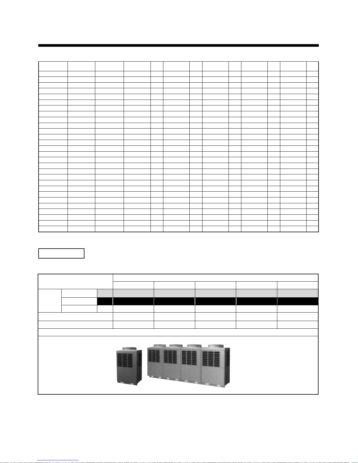
25
Modèle à thermopompe (60 Hz)
CV
(code de puissance)
5HP ( 5)
6HP ( 6)
8HP ( 8)
10HP (10)
12HP (12)
14HP (14)
16HP (16)
18HP (18)
20HP (20)
22HP (22)
22HP (22)
24HP (24)
24HP (24)
26HP (26)
28HP (28)
30HP (30)
32HP (32)
32HP (32)
34HP (34)
34HP (34)
36HP (36)
36HP (36)
38HP (38)
40HP (40)
42HP (42)
44HP (44)
46HP (46)
48HP (46)
Nom du modèle
MMY-
MAP0501HT7
MAP0601HT7
MAP0801HT7
MAP1001HT7
MAP1201HT7
AP1401HT7
AP1601HT7
AP1801HT7
AP2001HT7
AP2201HT7
AP2211HT7
AP2401HT7
AP2411HT7
AP2601HT7
AP2801HT7
AP3001HT7
AP3201HT7
AP3211HT7
AP3401HT7
AP3411HT7
AP3601HT7
AP3611HT7
AP3801HT7
AP4001HT7
AP4201HT7
AP4401HT7
AP4601HT7
AP4801HT7
Nombre d’unités
combinées
1
1
1
1
1
2
2
2
2
3
2
3
2
3
3
3
4
3
4
3
4
3
4
4
4
4
4
4
Inverseur 5 CV
Quantité
Inverseur 6 CV
Quantité
Inverseur 8 CV
Quantité
Inverseur 10 CV
Quantité
Inverseur 12 CV
Quantité
MMY-
utilisée
MMY-
utilisée
MMY-
utilisée
MMY-
utilisée
MMY-
utilisée
MAP0501HT7 1
MAP0601HT7 1
MAP0801HT7 1
MAP1001HT7 1
MAP1201HT7 1
MAP0601HT7 1 MAP0801HT7 1
MAP0801HT7 2
MAP0801HT7 1 MAP1001HT7 1
MAP1001HT7 2
MAP0601HT7 1 MAP0801HT7 2
MAP1001HT7 1 MAP1201HT7 1
MAP0801HT7 3
MAP1201HT7 2
MAP0801HT7 2 MAP1001HT7 1
MAP0801HT7 1 MAP1001HT7 2
MAP1001HT7 3
MAP0801HT7 4
MAP1001HT7 2 MAP1201HT7 1
MAP0801HT7 3 MAP1001HT7 1
MAP1001HT7 1 MAP1201HT7 2
MAP0801HT7 2 MAP1001HT7 2
MAP1201HT7 3
MAP0801HT7 1 MAP1001HT7 3
MAP1001HT7 4
MAP1001HT7 3 MAP1201HT7 1
MAP1001HT7 2 MAP1201HT7 2
MAP1001HT7 1 MAP1201HT7 3
MAP1201HT7 4
Equipements
1. Unit és extérieures
Inverseur
CV correspondants
5 CV 6 CV 8 CV 10 CV 12 CV
Thermopompe
MMY- MAP0501HT8 MAP0601HT8 MAP0801HT8 MAP1001H8 MAP1201HT8
Thermopompe
MMY- MAP0501HT7 MAP0601HT7 MAP0801HT7 MAP1001HT7 MAP1201HT7
Nom du
modèle
Froid seul
MMY- MAP0501T8 MAP0601T8 MAP0801T8 MAP1001T8 MAP1201T8
Puissance frigorifique (kW) 14.0 16.0 22.4 28.0 33.5
Puissance calorifique (kW) 16.0 18.0 25.0 31.5 37.5
Aspect
2
SELECTION DU LIEU D’INSTALLATION
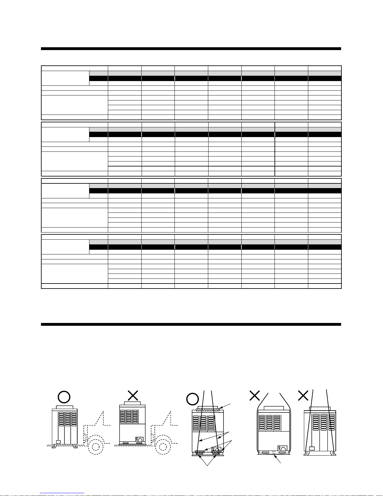
26
2.Unités extérieures (combinaison d’unités extérieures)
CV correspondants 5 CV 6 CV 8 CV 10 CV 12 CV 14 CV 16 CV
MMY- MAP0501HT8 MAP0601HT8 MAP0801HT8 MAP1001HT8 MAP1201HT8 AP1401HT8 AP1601HT8
MMY- MAP0501HT7 MAP0601HT7 MAP0801HT7 MAP1001HT7 MAP1201HT7 AP1401HT7 AP1601HT7
Modèle combiné
MMY- MAP0501T 8 MAP0601T8 MAP0801T8 MAP1001T8 MAP1201T8 AP1401T8 AP1601T8
Puissan ce fr ig ori f i que (k W) 14.0 16.0 22.4 28.0 33.5 38.4 45.0
Puissan ce ca l ori fi q ue ( kW ) 16.0 18.0 25.0 31.5 37.5 43.0 50.0
5 HP 6 HP 8 HP 10 HP 12 HP 8 HP 8 HP
—————6 HP 8 HP
———————
Unités extérieures combinées
———————
Nombre d’unités intérie ures à r ac corder 8 10 13 16 20 23 27
CV correspondants 18 CV 20 CV 22 CV 22 CV 24 CV 24 CV 26 CV
MMY- AP1801HT8 AP2001HT8 AP2201HT8 AP2211HT8 AP2401 HT8 AP2411HT8 AP2601HT8
MMY- AP1801HT7 AP2001HT7 AP2201HT7 AP2211HT7 AP2401 HT7 AP2411HT7 AP2601HT7
Modèle combiné
MMY- AP1801T8 AP2001T8 AP2201T8 AP2211T8 AP2401T8 AP2411T8 AP2601T8
Puissan ce fr ig ori f i que (k W) 50.4 56.0 61.5 61.5 68.0 68.0 73.0
Puissan ce ca l ori fi q ue ( kW ) 56.5 63.0 69.0 69.0 76.5 76.5 81.5
10 HP 10 HP 8 HP 12 HP 8 HP 12 HP 10 HP
8 HP 10 HP 8 HP 10 HP 8 HP 12 HP 8 HP
——6 HP — 8 HP — 8 HP
Unités extérieures combinées
———————
Nombre d’unités intérie ures à raccorder30333737404043
CV correspondants 28 CV 30 CV 32 CV 32 CV 34 CV 34 CV 36 CV
MMY- AP2801HT8 AP3001 HT8 AP3201HT8 A P 3211HT8 AP3401HT8 AP3411HT8 AP3601HT8
MMY- AP2801HT7 AP3001 HT7 AP3201HT7 A P 3211HT7 AP3401HT7 AP3411HT7 AP3601HT7
Modèle combiné
MMY-
AP2801T8 AP3001T8 AP3201T8 AP3211T8 AP3401T8 AP3411T8 AP3601T8
Puissance frigorifique (kW) 78.5 84 .0 90.0 90.0 96.0 96.0 101.0
Puissance calorifiq u e (kW) 88.0 95.0 100.0 100.0 108.0 108.0 113.0
10 HP 10 HP 8 HP 12 HP 10 HP 12 HP 10 HP
10 HP 10 HP 8 HP 10 HP 8 HP 12 HP 10 HP
8 HP 10 HP 8 HP 10 HP 8 HP 10 HP 8 HP
Unités extérieures combinées
——8 HP — 8 HP — 8 HP
Nombre d’unités intérie ures à raccorder47484848484848
CV correspondants 36 CV 38 CV 40 CV 42 CV 44 CV 46 CV 48 CV
MMY- AP3611HT8 AP3801 HT8 AP4001HT8 A P 4201HT8 AP4401HT8 AP4601HT8 AP4801HT8
MMY- AP3611HT7 AP3801 HT7 AP4001HT7 A P 4201HT7 AP4401HT7 AP4601HT7 AP4801HT7
Modèle combiné
MMY-
AP3611T8 AP3801T8 AP4001T8 AP4201T8 AP4401T8 AP4601T8 AP4801T8
Puissance fr i g orifique (kW) 101.0 106.5 112.0 118.0 123.5 130.0 135.0
Puissance calorifiq u e (kW) 113.0 119.5 126.5 132.0 138.0 145.0 150.0
12 HP 10 HP 10 HP 12 HP 12 HP 12 HP 12 HP
12 HP 10 HP 10 HP 10 HP 12 HP 12 HP 12 HP
12 HP 10 HP 10 HP 10 HP 10 HP 12 HP 12 HP
Unités extérieures combinées
— 8 HP 10 HP 10 HP 10 HP 10 HP 12 HP
Nombre d’unités intérie ures à raccorder48484848484848
3
TRANSPORT DE L’UNITE EXTERIEURE
Manipulez l’unité extérieure en tenant compte des points suivants.
1. Lorsque vous utilisez un élévateur à fourche, etc. pour charger/décharger l’unité lors du transport, insérez le
cliquet de l’élévateur à fourche dans le trou carré de manutention, comme indiqué ci-dessous.
2. Lorsque vous soulevez l’unité, insérez une corde qui supporte le poids de l’unité dans le trou carré de
manutention et encordez l’unité des quatre côtés. (Appliquez un sparadrap là où la corde touche l’unité
extérieure de sorte à ne provoquer aucune imperfection ou déformation sur la surface extérieure de l’unité.)
(Les plaques de renforcement sur les surfaces latérales empêchent la corde de glisser.)
Sparadrap
Corde
Sparadrap
Trou carré de manutention
Plaque de renforcement
Elévateur
à fourche
Elévateur
à fourche
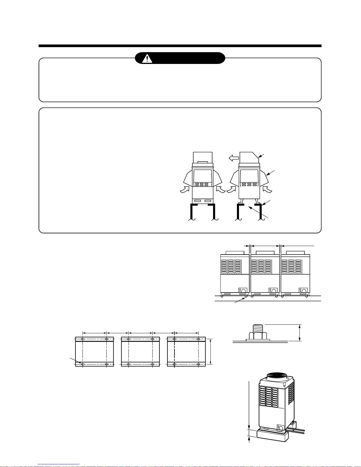
27
4
INSTALLATION DE L’UNITE EXTERIEURE
AVERTISSEMENT
Effectuez l’installation spécifiée contre les vents forts, comme le typhon, ou les tremblements de terre.
Si le climatiseur est mal installé, il peut tomber et provoquer un accident.
Installez solidement le climatiseur dans un endroit suffisamment résistant pour supporter son poids.
Si l’endroit n’est pas assez résistant, l’unité peut tomber et provoquer des blessures.
L’eau d’évacuation s’écoule de l’unité extérieure (Notamment en période de chauffage).
Installez l’unité extérieure dans un endroit favorable à l’évacuation.
Lors de l’installation, veillez à la résistance et au niveau de l’assise de sorte qu’aucun son
anormal (vibration, bruit) ne soit émis.
Pare-chutes de neige
pour la sortie d’air
Pare-chutes de
neige pour la
sortie d’air
(4 faces)
Support
Espace
d’évacuation
20mm ou plus 20mm ou plus
Boulon d’ancrage M12, 4 positions/unité
20
700
310 mm
ou plus
*
310 mm
ou plus
700 700
755
Trou continu
(trou long 15 x 20)
500mm ou plus
Dans les zones enneigées, prenez les mesures ciaprès pour protéger l’unité extérieure contre les chutes
de neige. (Voir figure de droite.) (Le non-respect des
mesures de protection contre les chutes de neige
provoquera une panne.)
Placez un support haut sous l’unité et montez les
pare-chutes de neige à l’entrée et à la sortie d’air de
sorte que la neige n’ait pas d’influence. (Effectuez
les travaux ci-dessus sur place.)
1. Pour installer plusieurs unités extérieures, disposez-les à
intervalles de 20 mm ou plus.
Fixez chaque unité extérieure avec des boulons d’ancrage M12
en 4 positions.
La longueur appropriée au boulon d’ancrage est de 20 mm.
• Le pas du boulon d’ancrage est indiqué ci-dessous.
2. Lorsque vous faites passer le tuyau de réfrigérant pas le bas, la hauteur du
support doit être de 500 mm ou plus.
 Loading...