

Page 1
TOSHIBA
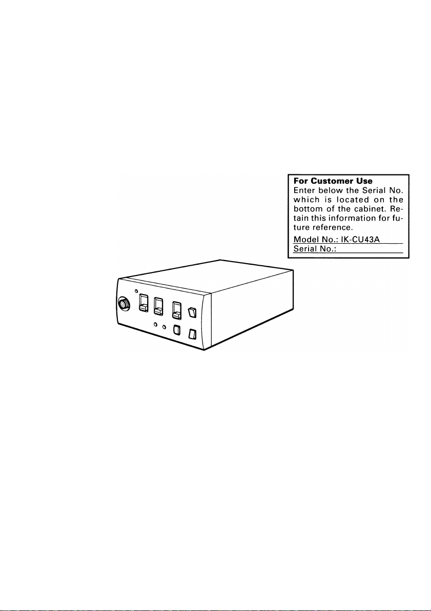
CAMERA CONTROL UNIT
IK-CU43A
INSTRUCTION MANUAL
INFORMATION
This equipment has been tested and found to comply with the limits for a Class A digital device,
pursuant to Part 15 of the FCC Rules. These limits are designed to provide reasonable protection
against harmful Interference when the equipment is operated in a commercial environment. This
equipment generates, uses, and can radiate radio frequency energy and, if not installed and used
in accordance with the instruction manual, may cause harmful interference to radio communica
tions. Operation of this equipment In a residential area is likely to cause harmful interference in
which case the user will be required to correct the Interference at his own expense.
USER-INSTALLER CAUTION: Your authority to operate this FCC verified equipment could be
voided if you make changes or modifications not expressly approved by the party responsible for
compliance to Part 15 of the FCC rules.
This Class A digital apparatus meets all requirements of the Canadian Interference Causing Equip
ment Regulations.
Cet appareil numérique de la classe A respecte toutes les exigences du Règlement sur le matériel
brouilleur du Canada.
Page 2

TABLE OF CONTENTS
1. COMPONENTS.....................................................................................................3
2. SPECIFICATIONS.................................................................................................3
3. NAMES AND FUNCTIONS
4. CONNECTION.......................................................................................................6
4.1 An Example of Standard Connection
4.2 Cautions on Connection.................................................................................6
4.3 Connection on Back Panel.............................................................................7
4.4 Connector Pin Assignments...........................................................................7
5. WHEN USING THE CAMERA WITH THE CAMERA UNIT FIXED
6. OPERATION..........................................................................................................9
6.1 AGC (Automatic Gain Control)
6.2 White Balance.................................................................................................9
(1) White balance adjustment in modes other than AUTO
(1.1) White balance adjustment in SET mode
(1.2) White balance adjustment in MANU mode...............................................10
6.3 FUNC LOCK Switch.....................................................................................10
7. MODE SETTING BY ON SCREEN DISPLAY
7.1 FILE (Scene File)..........................................................................................12
7.2 SHUTTER (Electronic Shutter, Backlight Correction)
(1) Detail setting in AUTO mode (auto electronic shutter)
(2) SS (synchronized scan)................................................................................13
7.3 Pedestal....................................................................................................... 14
7.4 SYNC (Setting for External Synchronization)...............................................14
7.5 AREA (Measurement Area)..........................................................................15
(1) Setting AREA the same for AGC,
auto electronic shutter and white balance
(2) Setting AREA separately for AGC,
auto electronic shutter and white balance
7.6 WB-OFFSET (White Balance Offset)
7.7 INIT. (Scene File Initialization)......................................................................18
7.8 END (Ending ON SCREEN DISPLAY).........................................................18
8 EXTERNAL SYNC.................................................................................................19
9. CAUTIONS ON USE AND INSTALLATION......................................................20
10. BEFORE MAKING A SERVICE CALL
11. OPTIONAL PARTS.............................................................................................21
12. EXTERIOR DIMENSIONS
...................................................................................
..............................................................
.......................
.......................................................................
.................................
..................................................
....................................................
...................................
.................................
....................................................
....................................................
...........................................................
................................................................
..................................................................................
4
6
8
9
10
10
11
12
13
15
16
17
20
22
Page 3

1. COMPONENTS
(1) Camera control unit
(2) Accessories
(a) Instruction manual,
.............
2. SPECIFICATIONS
Specification with camera head (IK-M43H) connected.
Power supply
Power consumption 310 mA
Image sensor
Effective pixels
Effective image area
Scanning system
Scan frequency
Sync system
Resolution
Standard intensity of
illumination for objects
Minimum intensity of
illumination for objects
S/N ratio
Video output
Output impedance
External
sync
White balance
Gain switch (AGO
Electronic shutter
Operating temperature/
humidity
Anti-vibration/
shock characteristics
Weight
Dimensions
(Without protrusion)
Input
Adjustment
function
DC12V + 0.5V
1/2 inch IT-CCD
Horizontal: 768 pixels, Vertical: 494 pixels
Horizontal: 6.54 mm, Vertical: 4.89 mm (1/2 inch type)
2:1 interlace
Horizontal: 15.734 kHz, Vertical: 59.94 Hz
Internal/External (automatic switching)
Horizontal: More than 470 lines. Vertical: More than 350 lines
60 lx (FI.6, 3000K)
5 lx (F1.6, 3000K)
46 dB or more
VBS 1.0 V(p-p), (BNC terminal) NTSC system
Y/C separation output (S terminal)
75Q unbalanced
VBS 1.0 V(p-p) (BNC terminal) NTSC 75Q unbalanced
Subcarrier phase, H phase
Automatic/set/manual
SENS UP (+6 dB)/ON/OFF
Automatic, 1/60s, 1/100s, 1/250s, 1/500s, 1/IOOOs, 1/2000s,
1/4000S, 1/IOOOOs, synchronized scan
14°F to 104°F (-10°C to +40°C)/Less than 90%
70 m/s^ (10 to 200 Hz)/700 m/s^
Control unit: 0.86 lbs (390g)
Control unit: W: 3.35", H: 1.57", D: 6.14"
(W: 85 mm, H: 40 mm, D: 156 mm)
Design and specifications are subject to change without notice.
Page 4
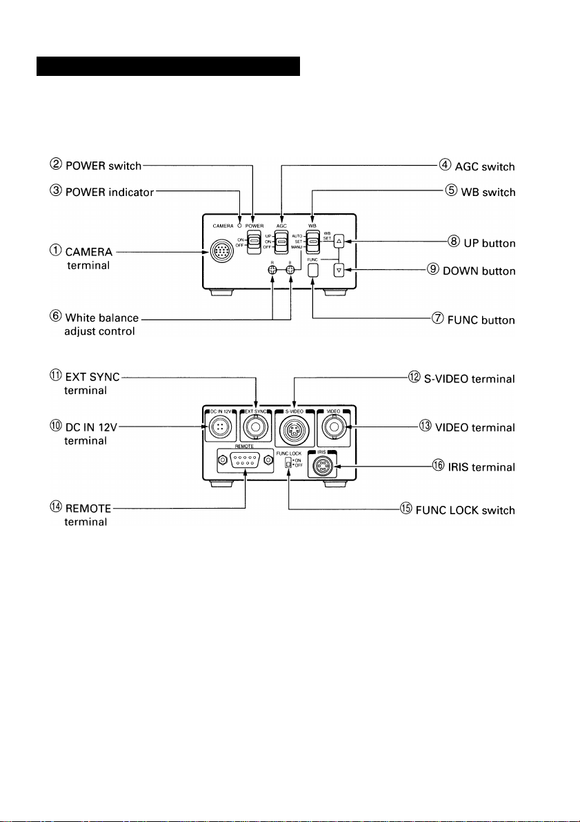
3. NAMES AND FUNCTIONS
Page 5

® CAMERA terminal
® POWER switch
(3) POWER indicator
® AGC switch
® WB switch
© White balance adjust control
@ FUNC button
® UP button
® DOWN button
® DC IN 12V terminal
© EXT SYNC terminal
® S-VIDEO terminal
® VIDEO terminal
REMOTE terminal
FUNC LOCK switch
IRIS terminal
Connects to the camera head.
Turns on and off the camera control unit.
Lights up when the power is turned on.
Selects the gain mode. (AGC OFF/AGC ON/SENS UP)
Selects the white balance mode. (MANU/SET/AUTO)
Adjusts the R gain and B gain with the white balance
mode set to MANU by the WB switch ®.
Determines the setting indication contents when the set
ting menu is displayed on the screen.
Selects the setting item when the setting menu is dis
played on the screen. (When the WB switch ® is set to
SET, pressing the UP button for more than 2 sec. acti
vates the white balance SET operation.)
Selects the setting item when the setting menu is dis
played on the screen.
Accepts a DC power supply (12V).
Accepts an external sync signal to synchronize the cam
era output signal with external signal.
Connects terminal to S input terminal of a monitor or a
VCR, etc.
Can be used at the same time as video terminal.
Connects terminal to video input terminal of a monitor
or a VCR, etc.
Can be used at the same time with the S-VIDEO termi
nal.
Controls the functions via RS232C.
Locks the switches and control on the front panel. When
the FUNC LOCK switch is set to ON, all settings except
for the POWER switch ® and the file item of the screen
setting menu are locked out.
Connect when using an automatic iris lens.
Page 6
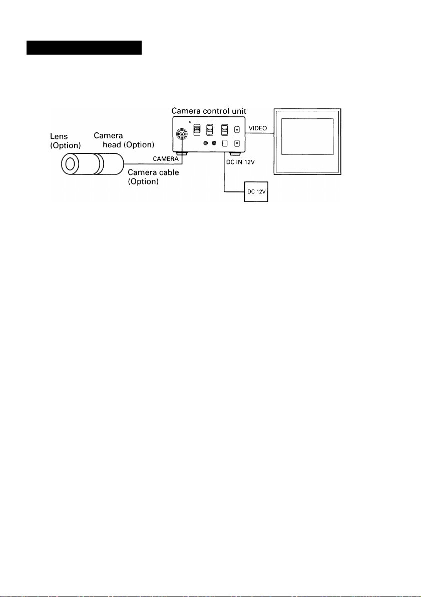
4. CONNECTION
"O* i AM KJElliiipFllS IPW MMPHHMET* %lPliillililiBii
Monitor
DC power supply
4.2 CuvMmw on Connoction
• When connecting or disconnecting the camera cables (for the camera head and
camera control unit), always turn off the power switch of the camera control unit
first. If not, the camera head may be damaged.
• When connecting the camera, always turn off the power of the camera control
unit and any other equipment connected.
© Remove the camera head protection cover and mount a lens (option).
® Connect the camera head and the camera control unit with the camera cable
(option).
@ Connect the VIDEO (or S-VIDEO) terminal of the camera control unit to a video
input terminal of a monitor, etc.
® Connect a DC power supply (12V) to the DC IN 12V terminal of the camera control
unit.
• For DC power supply connecting to DC IN 12V terminal, use UL listed and/or CSA
approved ungrounding type AC adaptor with the specifications described below.
Power supply voltage: DC12V±0.5V
Current rating: More than 800 mA
Ripple voltage: Less than 50 mV(p-p)
Connector: HR10A-7P-4S (Hirose)
Pins 1, 2:©, Pins3, 4:0
Page 7
4.3 4MI fcwrik ]
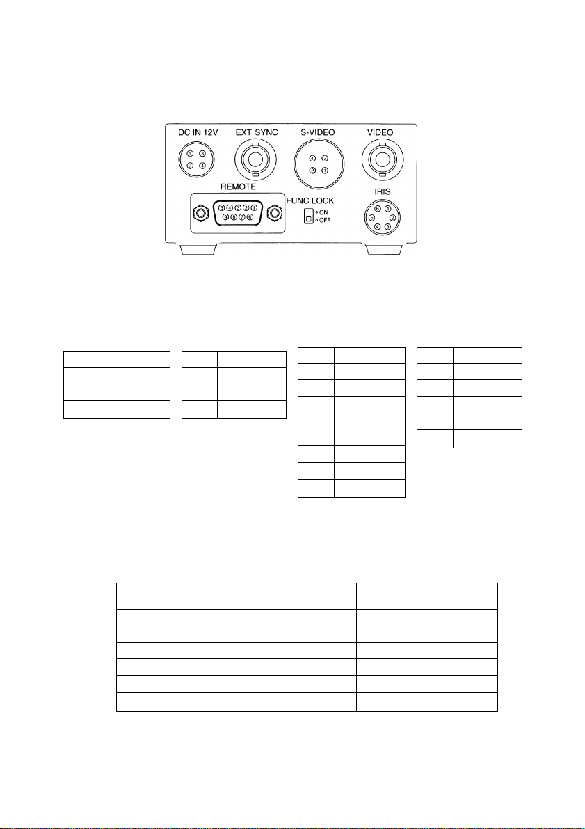
The figure below shows the back panel connection terminals of the camera control unit.
4»4 C0iiiieiHl0i* Pill AssigiiM#irts
DC IN 12V
1 + 12V
2 + 12V
GND
3
4
GND
* When using the REMOTE terminal, please consult with your dealer.
Using the auto-iris lens
The following table shows the IRIS terminal when using the auto-iris (EE) lens.
Table 1
IRIS Connector
The IRIS connector used for the IRIS terminal: HR10A-7P-6P of HIROSE ELECTRIC
CO., LTD.
S-VIDEO
1 GND
2 GND
Y
3
4
C
Terminal No.
1
2 Video signal
3
4 Power (DC)
5
6
Signal
—
GND
(GND)
—
REMOTE
1
2
3 RXD
4
5
6
7
8
9 NC
NC
TXD
DSR
GND
DTR
CTS
RTS
+ 12V (less than 50mA)
IRIS
1
2
3
4
5
6
Rated
0.8± O.IVp-p
NC
VIDEO
GND
+ 12V
GND
NC
Page 8

• EE lens
The IRIS extension cable (optional) is usable for the EE lens. Use the connector HR10A-
7P-4P of HIROSE when the IRIS extension cable is selected. For connections, follow the
instruction below.
When the IRIS extension cable is used under
the right condition, the cable automatically
converts to connection for th’e EE lens In
Table 1. Seethe Chapter OPTIONS for the IRIS
extension cable.
Notes:
• Current consumption must be 50 mA or less.
• Avoid an incorrect connection or short-circuit.
EE lens connector —
HR10A-7P-4P
Power (+)
GND
Video signal
Unconnected or ground
5. WHEN USING THE CAMERA WITH THE CAMERA UNIT FIXED
The camera control unit can be directly mounted by using M3 screws If the four rubber
feet are removed on bottom of the control unit. When mounting directly as described
above, do not use longer screws. If the screws enter by more than 5 mm from the control
unit mounting surface, they will cause a short-circuit inside the control unit. For details of
screw hole locations, refer to the exterior dimensions of the camera control unit.
Page 9

6. OPERATION
Turn on the POWER switch on the camera control unit and adjust the lens iris and focus
while observing a picture on the monitor screen. To obtain the best picture quality, per
form various settings.
«.1 AGC lAntowotic G«lii CmItoI}
AGO functions "OFF", "ON" or "UP" can be selected on the screen menu. Generally, the
camera is used with the AGO set to OFF, but when increased camera sensitivity is re
quired, it is set to ON. When more sensitivity is required, "UP" is selected. With the AGO
ON, the camera sensitivity approximately doubles, and with the UP selected the sensitiv
ity approximately doubles again, but noise will also Increase. We recommend you in
crease intensity of the lighting to obtain good pictures.
The AGO measurement area is the same as that used for "AREA". (Refer to item 7.5)
6.2 White Baiane»
A white balance adjustment is necessary to obtain pictures with correct color tone. This
camera allows you to select the white balance adjustment of "AUTO", "SET", and
"MANU". With the AUTO mode selected, the camera adjusts the white balance automati
cally. Most shooting will be made in the AUTO mode. The color temperature applicable to
this camera is approximately 2500 to 7000K.
Outline
Features
Notes
AUTO
Camera automati
cally measures
object color
temperature and
adjusts the white
balance.
Automatically traces
variations of color
temperature and
adjusts the white
balance.
Under poor illumina
tion, white balance
may not be correct.
SET MANU
Adjust white balance
by pressing "UP"
button on the
camera control unit
while shooting a
white object.
Measurement
accuracy is higher
than AUTO mode.
This mode is
effective when
shooting under less
variations of color
temperature.
Adjust R (red) and B
(blue) levels on the
control unit while
shooting a white
object.
Measurement
accuracy is higher
than SET mode.
This mode is
effective for users
desiring specific
color temperature,
also effective when
shooting under the
least variations of
color temperature.
Adjustment will be
made by viewing
monitor or vector
scope.
Page 10

(1) White balance adfustment in modes other than AUTO
(1.1) White balance adjustment in SET mode
© Set the WB switch to "SET" position.
@ Shoot a white object to fill entire screen and press the UP button ([X]) fo*” about 2
sec.
® When the white balance adjustment completes, the letters "WB SET" blinking at
the upper right of the screen changes to "WB OK" and then turns off. If the "WB
NG" Is displayed, it shows the white balance is out of the adjustment range. This
is caused by the object not being white enough, or the video level is set too high
or too low even if the white object is shot. Shoot the white object or set the video
level correctly.
Note;
• With the screen menu displayed, the UP button is used for moving the
cursor or modifying the data. To activate the SET mode by pressing the
UP button, turn off the screen menu.
(1.2) White balance adjustment in MANU mode
® Set the WB switch to "MANU" position.
(D Shoot the white object and adjust the white balance by adjusting the white bal
ance adjust controls "R" and "B" with the screwdriver while observing the moni
tor or vector scope.
«.3 nine LOCK Mtch
The FUNC LOCK switch protects settings even if a
switch is accidentally pressed after setting. When
the FUNC LOCK switch is ON, only the following
functions are available.
POWER switch (ON/OFF)
FILE (A/B) In menu
Settings will not be changed even if the other
switches are operated. In the menu screen, all ex
cept FILE and END are displayed in black letters
(white when the FUNC LOCK switch is OFF) and
"FUNCTION LOCK ACTIVE" blinks to indicate that
the FUNC LOCK switch is ON.
IfileI A
SHUTTER
PEDESTAL
SYNC INT
AREA
WB-OFFSET
INIT .
END
FUNCTION
PUSHIfunc
AUTO
00
LINK:1
00
LOCK ACTIVE
1 TO SELECT
10
Page 11

7. MODE SETTING BY ON SCREEN DISPLAY
Setting while nnonitoring the menu on the monitor screen is possible. The following seven
items can be set.
® Scene file
(D Electronic shutter (AUTO/MANUAL), backlight correction
@ Pedestal level
® Phase matching in external synchronization (horizontal/subcarrier synchronization)
® White balance, auto electronic shutter, AGC measurement area
® White balance offset
® Scene file factory setting
Press the FUNC button to display the menu. The
menu appears as shown on the right. Current set
ting is displayed. Move the cursor to a desired item
by moving the cursor up or down using the UP and
DOWN buttons, and set an Item by pressing the
FUNC button. To quit the menu, move the cursor to
END and press the FUNC button.
UP button:
The cursor position or
data value goes up.
FUNC
f 1 [ V — DOWN button: The cursor position or
data value goes down.
FUNC button: Selects the item or
data value.
Notes:
• When setting is changed in the menu screen,
be sure to move the cursor to "END" and
press the FUNC button to turn off the menu.
New setting is stored in the camera.
• Don't turn off the POWER switch before
turning off the menu. New setting is not
stored, and old data remains.
Main Menu
IfileI
SHUTTER
PEDESTAL
SYNC INT
AREA LINK:1
WB-OFFSET 00
INIT.
END
PUSHIfuncI
A
AUTO
00
TO SELECT
11
Page 12

7.1 nu IScMM iil*|
There are two scene files A and B which can be se
lected according to the shooting state.
® Move the cursor to "FILE" in the main menu us
ing the UP or DOWN button.
@ Press the FUNC button to display the contents to
set FILE, A or B. Move the cursor to A or B using
the UP or DOWN button. Press the FUNC button
to set the contents.
Note:
• The scene file is for the menu screen. The
AGC switch and the WB switch are only
valid in their set positions.
• The new settings are memorized when the
POWER is turned off.
7.2 SHUmR {UMtrmiic SIhKHNmv BmkIIgM OmtmMwìI
The electronic shutter is available In AUTO (auto
electronic shutter), 1/60 ~ 1/10000 and SS (synchro
nized scan).
AUTO: Controls electronic shutter automati
cally to output the set video level. Can
be selected in backlight correction,
peak measurement, average mea
surement and measurement area.
1/60-1/10000: Exposure time can be fixed to any one
of 1/60, 1/100, 1/250. 1/500, 1/1000,
1/2000, 1/4000 and 1/10000.
SS: Sets the electronic shutter In horizon
tal scanning time intervals of 1H.
® Move the cursor to "SHUTTER" in the main menu
using the UP or DOWN button.
@ Press the FUNC button to display AUTO - EXIT
to set SHUTTER. Move the cursor to a desired
Item of AUTO - SS using the UP or DOWN but
tons. Press the FUNC button to frame a desired
Item in white.
@ Move the cursor to "EXIT" using the UP or DOWN
button. Press the FUNC button. Return to the
main menu.
12
IfileI A
SHUTTER
PEDESTAL
SYNC I NT
AREA
WB-OFFSET 00
INIT .
END
PUSH 1 FUNC1TO SELECT
FI
SHUTTER
PEDESTAL
SYNC
AREA
WB-OFFSET
L N T T .
END
PUSH I FUNc] TO SELECT
FILE
|SHUTTER~|
PEDESTAL
SYNC
AREA
WB-OFFSET
INIT .
END
PUSH I FUNCiTO SELECT
FILE
¡SHUTTER 1
PEDESTAL
SYNC
AREA 1/1000
WB-OFFSET
INIT .
END SS 262/525H
PUSHIfuncI
AUTO
00
LINK:1
A
0
AUTO
00
I NT
LINK : 1
00
1AUTOl
1/60
1/100
1/250
1/500
1/2000
1/4000
1/10000
EXIT
TO SUB MENU
Page 13

(1) Detail setting in AUTO mode (auto electronic shutter)
When the FUNC button is pressed after AUTO is se
lected, the submenu for SHUTTER:AUTO appears.
Set details in this screen.
LEVEL: Adjust the auto electronic shutter
video level. Larger values indicates
brighter level, and vice versa. Data can
be set in a range of -30 to +30.
BLC: Correction for backlight. This can be
set when the measurement area is set
to one of "1/2", "1/8" and "SLIT" for
AREA in the main menu. Backlight is
corrected at ON, but not at OFF. When
the measurement area is "1", BLC is
displayed in black letters and setting
is impossible.
PEAKiAVE: Selects peak or average for measure
ment of auto electronic shutter video
level. The peak to average ratio can
be changed in a range of 00:10 to
10:00.
Note:
• While BLC is ON, PEAKzAVE is displayed in
black letters and setting is impossible.
© Move the cursor to a desired item (LEVEL, BLC,
PEAK:AVE) using the UP or DOWN button. Press
the FUNC button. The cursor moves to the data
of the selected item. Set the data by pressing the
UP or DOWN button.
@ After setting the data, press the FUNC button. The
cursor moves to the item. To finish setting of
submenu, move the cursor to "EXIT" and press
the FUNC button to return to "SHUTTER" in the
main menu.
(2) SS (synchronized scan)
© Move the cursor to "SS" using the UP or DOWN
button. Press the FUNC button. (SS is set.)
@ Press the FUNC button. The cursor moves to the
data and blinks. The data varies in 1/525H to 262/
525H when the UP or DOWN button is pressed.
Set a desired data, and press the FUNC button.
@ Return to "SS" of SHUTTER.
; :|auto I
1AUTO|
1/60
1/500
1/2000
1/4000
1/10000
EXIT
TO SUB MENU
SUB MENU
00
OEF
00:10
FILE
ISHUTTER1 1/100
PEDESTAL 1/260
SYNC
AREA 1/1000
WB-OFFSET
INIT .
END SS 262/525H
PUSH IfuncI
IlevelI
BLC
PEAK:AVE
EXIT
PUSH FUNC TO SELECT
SHUTTER :|aUTO | SUB MENU
IlevelI | oq |
BLC
PEAK:AVE
EXIT
PUSH FUNC TO SELECT
Example of display for LEVEL
FILE
ISHUTTER1 1/100
PEDESTAL
SYNC
AREA 1/1000
WB-OFFSET
INIT .
END
PUSH IfuncI
AUTO
1/60
1/250
1/500
1/2000
1/4000
1/10000
|ss||262/525h|
EXIT
TO SELECT
13
Page 14

7.3 INMkMrtal
© Move the cursor to PEDESTAL using the UP or
DOWN button.
@ Press the FUNC button. The cursor moves to the
data. Set the data using the UP or DOWN button.
The data can be set in a range of-50 to +50. After
setting the data, press the FUNC button to return
to the main menu.
FILE
SHUTTER
IpedestalI
SYNC
AREA
WB-OFFSET
INIT .
END
PUSH I FUNCI TO SELECT
EILE
SHUTTER
Ipedest^
SYNC
AREA
WB-OFESET
INIT .
END
PUSH FUNC TO SELECT
7.4 tHK fM* liiiMnmil %«MdhNrwÉfaHHriMk^
This adjusts horizontal phase and subcarrier phase
while externally synchronized. INT Is displayed for
internal synchronization and changed automatically
to EXT when the external synchronizing signal is en
tered.
® Move the cursor to "SYNC" using the UP or
DOWN button.
® Press the FUNC button to display the available
items (H-PHS, SC-PHS, SC-FINE).
H-PHS: H (horizontal) phase matching 0 ~ 99
SC-PHS: SC (subcarrier) rough adjustment 0,
90, 180, 270
SC-FINE: SC (subcarrier) fine adjustment 0 ~ 99
FILE
SHUTTER
PEDESTAL
ISYNCI
AREA
WB-OFFSET
INIT .
END
PUSH 1 FUNCiTO SELECT
FILE
SHUTTER
PEDESTAL
AREA
WB-OFFSET
INIT .
END
PUSH |fun~c1 to select
A
AUTO
00
INT
LINK:1
00
[ÓÓ]
A
AUTO
00
INT
LINK:1
00
A
AUTO
00
EXT.VBS
LINK :1
00
14
Page 15

Move the cursor to a desired item (H-PHS, SCPHS, SC-FINE) using the UP or DOWN button.
Press the FUNC button and the data is displayed.
Set the data using the UP or DOWN button and
press the FUNC button to select the data. To re
turn to the main menu, move the cursor to EXIT
and press the FUNC button.
Note:
If the internal synchronization is set while
the SYNC item (H-PHS, SC-PHS, SC-FINE) is
being displayed, the display automatically
turns to INT, disabling setting.
FILE
SHUTTER
PEDESTAL
AREA
WB-OFFSET
INIT .
END
PUSH I FUNCI TO SELECT
|h-phs| 50
SC-PHS 0
sc- FINE 50
EXIT
[ y.S IMMm Anwil
AREA is a measurement AREA item for AGC, auto
electronic shutter and white balance. The AREA set
ting for AGC and auto electronic shutter are the
same, so each setting can not be made separately.
However, the AREA setting for white balance can
be made Independently from the AREA setting for
AGC and auto electronic shutter.
FILE
SHUTTER
PEDESTAL
SYNC
Iarea] LINK:1
WB-OFFSET
INIT .
END
PUSH|func|
© Move the cursor to AREA using the UP or DOWN
button.
® Press the FUNC button to display the available
items (LINK, SEP).
® Move the cursor to a desired item (LINK, SEP)
using the UP or DOWN button.
(1) Setting AREA the same for AGC, auto electronic shutter and
white balance
® Move the cursor to LINK using the UP or DOWN
button.
EILE
SHUTTER
PEDESTAL
SYNC
IaREaI
WB-OEFSET SEP
INIT .
END
PUSH I FUNCI TO SELECT
A
AUTO
00
INT
00
TO SELECT
_______
I
LINkI: I
EXIT
15
Page 16

Press the FUNC button to display data 1 ~ SLIT
for LINK. Move the cursor to a desired item of
AREA data (1, 1/2, 1/8, SLIT) using the UP or
DOWN button.
Press the FUNC button to set the data.
FILE
SHUTTER
PEDESTAL
SYNC
IareaI
WB-OFFSET SEP 1/2
INIT .
END
PUSH 1 EUNC1
(2) Setting AREA for white balance separately from the AREA
setting for AGC and auto electronic shutter
© Move the cursor to SEP using the UP or DOWN
button, and press the FUNC button. SEP is se
lected and framed in white.
@ Press the FUNC button to display the submenu.
@ Move the cursor to a desired item using UP or
DOWN button.
WB: Measurement AREA forwhite balance
1, 1/2, 1/8, SLIT
Valid when the WB switch is AUTO
and/or SET.
SHUTTER: Measurement AREA for auto elec
tronic shutter and AGC
1, 1/2, 1/8, SLIT
® Press the FUNC button to select a desired item.
The setting data (1, 1/2, 1/8, SLIT) is displayed.
Move the cursor to a desired item using UP or
DOWN button, then press the FUNC button to
select the data.
® The submenu for AREA appears. Move the cur
sor to EXIT, and press the FUNC button to return
to the main menu.
FILE
SHUTTER
PEDESTAL
SYNC
|aREa| LINK:1
WB-OEESET I SEP|
INIT .
END
PUSH I RUNG I TO SELECT
AREA:[SEP]
|wb|
SHUTTER
EXIT
PUSH I FUNCI TO SELECT
1 link|[T1
EXIT 1/8
SLIT
TO SELECT
EXIT
The size of AREA is approximately as shown below.
(1) 1 (Whole monitor screen)
(3) 1/8
(2) 1/2
(4) SLIT
fv
16
6^^
8 ''
|v
AREA :|SEP|
|wb|
SHUTTER
EXIT
PUSH [ EUNC1
SUB MENU
m
1/2
1/8
SLIT
TO SELECT
Page 17

inínIMPPPiSfNRi wHEMHRNMMI wVfJMW|
This offsets the white balance in the direction of
orange or cyan when the WB switch is set to "SET".
© Move the cursor to WB-OFFSET using the UP or
DOWN button.
@ Press the FUNC button. The cursor nnoves to the
data item.
@ Change the data using the UP or DOWN button.
+20 ~-20
+ Orange direction
- Cyan direction
Press the FUNC button at a desired data value to
set the data.
FILE A
SHUTTER AUTO
PEDESTAL 00
SYNC
AREA LINK:1
1 wb-ofeset|
INIT.
END
PUSH IfuncI
FILE
SHUTTER
PEDESTAL
SYNC
AREA
|wb-offset|
INIT .
END
PUSH I fun's] to select
INT
00
TO . SELECT
ÍTÓ]
17
Page 18

7.y Mill. H—w wnm IwifiqliKqflgit) ]
This reset settings of the scene file to the factory
setting.
® Select a scene file (A or B) to initialize the setting
in FILE.
(D Move the cursor to INIT. using the UP or DOWN
button.
(3) Press the FUNC button. The selected scene file
(A or B) is displayed. NO/YES Is displayed.
® Select NO when not initializing. Select YES and
press the FUNC button when initializing.
Factory setting (the following setting if INIT. is executed)
The setting is common to scene files A and B.
FILE A
SHUTTER AUTO
PEDESTAL 00
SYNC
AREA
WB-OFFSET 00
1 INIT .1
END
PUSH IfuncI
TNT
LINK : 1
TO SELECT
SHUTTER
PEDESTAL
SYNC
AREA
WB-OFESET 00
AUTO
--
00
EXT.VBS
LINK:1 -
R
SEP WB
SHUTTER
7.8 Mm (Ending ON SCiEIN DISMAY)
To turn off the menu, move the cursor to END using
the UP or DOWN button and press the FUNC but
ton. To store the setting in the camera, be sure to
turn off the display by pressing END. When the dis
play is turned off, the setting is stored in the cam
era. If the POWER switch is turned off while the menu
Is being displayed, the setting is not stored and the
old data remains.
18
H-PHS
SC-PHS
P
SC-FINE
— BLC OFF
50
0
50
FILE
SHUTTERAAUTO
PEDESTAL 00
SYNC
AREA LINK : 1
WB-OFFSET
I N T T .
1 end|
PUSH 1 FUNC1TO SELEC"
LEVEL 00
PEAK:AVE 00:10
I NT
00
Page 19

8 EXTERNAL SYNC
When using the camera with external sync, connect a composite video signal (C-VIDEO)
to the EXT SYNC terminal on back of the camera control unit. When the camera accepts
external sync, it is automatically switched from the internal sync to the external sync.
( 1 ) External sync signal Input conditions
C-VIDEO
(75Î2 unbalanced)
SYNC section
BURST section
0.3 ± 0.1V
0.3 ± 0.1V
(2) External sync frequency range
Within ±50 ppm in reference to NTSC standard frequency
(H frequency 15733.5 Hz to 15735.0 Hz)
(3) Using the camera with external sync signal
When using more than two cameras in external synchronization, this adjustment allows
matching of color tone between two cameras. Adjust H (horizontal) phase and SC (sub
carrier) phase if necessary.
(3.1) H (horizontal) phase adjustment
Observe the external sync signal and video out
put signal on the camera with a dual trace oscil
loscope, and adjust "H-PHS" of "SYNC" on the
screen menu so that the H phase matches.
(3.2) SC (sub carrier) phase adjustment
Perform a coarse adjustment for 0, 90, 180, or
270 degrees in "SC-PHS" on the screen menu and then perform a fine adjustment with
"SC-FINE". Using a vector scope for the phase adjustment will provide more accuracy.
Match
the phase.
i/%v
External
sync, signal
Camera
video output
19
Page 20

9. CAUTIONS ON USE AND INSTALLATION
Carefully handle the units.
Do not drop or give a strong shock or vibra
tion to the camera. This may cause prob
lems. Treat the camera cables carefully to
prevent cable problems such as cable break
down and loosened connections.
Do not shoot intense light.
If there is an intense light at a location on
the screen such as a spot light, blooming and
smearing may occur.
Do not aim the camera at the sun. If an in
tense light enters, vertical stripes may ap
pear on the screen.
Lens treatment.
Do not look at the sun through the lens.
Handling of the camera head and pro
tection cover.
Keep the camera head and the protection
cover away from children. Children may put
them into mouth or swallow them acciden
tally. The protection cover protects the im
age sensing plane when the lens is removed
from the camera head, do not throw away.
Do not touch internal parts.
Tampering with the internal parts may cause
operation failure or injury.
Operating ambient temperature and hu
midity.
Do not use the camera in places where tem
perature and humidity exceed the specifica
tions. Picture quality will degrade and inter
nal parts may be damaged.
• Do not splash water.
Install the camera in a location free from
water splash. If splashed, turn off the cam
era power switch and stop supplying power,
then consult with your dealer.
• Install the camera in a location free
from noise.
If the camera or the cables are located near
power utility lines or a TV, etc. undesirable
noise may appear on the screen. In such a
case, try to change the location of the cam
era or the cable wiring.
• When not using the camera for a long
time.
Turn off the camera power switch and stop
supplying power.
• Should you notice any trouble.
If an abnormality occurs such as no picture
obtained, turn the camera power switch off
and stop supplying power, then consult with
the dealer. Using the camera without check
ing the cause of the trouble may lead to fur
ther damage or unexpected accident.
• When cleaning the camera
Always turn off the power and make a clean
ing with a piece of dry cloth. If necessary,
gently wipe with a cloth dampened with
thinned detergent. Do not use benzine, al
cohol, thinner, etc. If used, coating and
printed letters may be discolored. When
cleaning the lens, use a lens cleaning paper,
etc.
10. BEFORE MAKING A SERVICE CALL
Symptom
No picture
Poor color
"HEAD UNCONNECTED"
or "CABLE DETECT ERR"
is displayed on the screen
20
• Is the power supplied correctly?
• Is the lens iris adjusted correctly?
• Are the cables connected correctly?
• Is the monitor (TV) adjusted correctly?
• Is the white balance of the camera adjusted correctly?
(in modes other than automatic trace)
• Is the illumination dark?
• Is the SC phase adjusted correctly? (External sync)
• Turn the power of the camera off, make proper connec
tion for the camera head, camera cable, and camera
control unit, and then turn the power on again. (Im
proper connection may cause the trouble.)
Items to be checked
Page 21

1 1. OPTIONAL PARTS
For further details, call the dealers.
Camera head
Type name
IK-SM43H
IK-C43H
IK-M43H
7mm Camera head
C mount head
17mm Camera head
21
Page 22

1 2. EXTERIOR DIMENSIONS
Cciiwrq Coitfrol HnR ]
20 21.5 21.5
Unit: mm [inch]
22
Page 23

LIMITED WARRANTY
Toshiba America Information Systems, Inc. (“TAIS”), makes the following limited warranties. These limited warranties
extend to the original enduser/purchaser.
Limited One (1) Year Warranty of Labor and Parts
TAIS warrants this product and its parts against defects in materials or workmanship for a period of one year after the
date of original retail purchase.
During this period, TAIS will repair a defective product or part, without charge to you. You must deliver the entire
product to a TAIS Service Center.
You pay for all transportation and insurance charges for the product to the Service Center.
Instruction Manual (Owner’s Manual)
You should read the instruction manual (owner’s manual) thoroughly before operating this product.
Your Responsibility
The above warranties are subject to the following conditions:
1. You must retain your bill of sale or provide other proof of purchase.
2. You must notify TAIS Service within thirty (30) days after you discover a defective product or part.
3. All warranty servicing of this product must be made by TAIS Service Center.
4. These warranties are effective only if the product is purchased and operated in the U.S.A.
5. Labor service charges for installation and adjustment of customer controls are not covered by this warranty.
6. Warranties extend only to defects in materials or workmanship as limited above and do not extend to any product
or parts which have been lost or discarded by you or to damage to products or parts caused by misuse, accident,
improper installation, improper maintenance or use in violation of instructions furnished by us; or to units which
have been altered or modified without authorization of TAIS or to damage to products or parts thereof which have
had the serial number removed, altered, defaced or rendered illegible.
Step-By-Step Procedures - How to Obtain Warranty Service
To obtain warranty servicing, you should:
1. Contact TAIS Service Center listed below for warranty service within thirty (30) days after you find a defective
product or part.
2. Arrange for the delivery of the product to TAIS Service Center. Products shipped to the Service Center must be
insured and safely and securely packed, preferably in the original shipping carton, and a letter explaining the
defect and also a copy of the bill of sale or other proof of purchase must be enclosed. All transportation and
insurance charges must be prepaid by you.
3. If you have any questions about service, please contact the following TAIS Service Center:
9740 Irvine Blvd. Irvine, CA 92713-9724
Phone Number: (714) 583-3000
ALL WARRANTIES IMPLIED BY STATE LAW, INCLUDING THE IMPLIED WARRANTIES OF MERCHANTABILITY
AND FITNESS FOR A PARTICULAR PURPOSE, ARE EXPRESSLY LIMITED TO THE DURATION OF THE LIM
ITED WARRANTIES SET FORTH ABOVE.
limitation may not apply to you
LIMITED, THE FOREGOING EXPRESS WARRANTY IS EXCLUSIVE AND IN LIEU OF ALL OTHER WARRAN
TIES, GUARANTEES, AGREEMENTS AND SIMILAR OBLIGATIONS OF MANUFACTURER OR SELLER WITH
RESPECT TO THE REPAIR OR REPLACEMENT OF ANY PRODUCT OR PARTS.
IN NO EVENT SHALL TAIS BE LIABLE FOR CONSEQUENTIAL OR INCIDENTAL DAMAGES.
the exclusion or limitation of incidental or consequential damages so the above limitation may not apply to you.
No person, agent, distributor, dealer, service station or company is authorized to change, modify or extend the terms
of these warranties in any manner whatsoever. The time within which an action must be commenced to enforce any
obligation of TAIS arising under this warranty or under any statute, or law of the United States or any state thereof, is
hereby limited to one year from the date you discover or should have discovered, the defect. This limitation does not
apply to implied warranties arising under state law. Some states do not permit limitation of the time within which you
may bring an action beyond the limits provided by state law so the above provision may not apply to you. This
warranty gives you specific legal rights and you may also have other rights which vary from state to state.
WITH THE EXCEPTION OF ANY WARRANTIES IMPLIED BY STATE LAW AS HEREBY
Some states do not allow limitations on how long an implied warranty lasts, so the above
Some states do not allow
TOSHIBA AMERICA INFORMATION SYSTEMS, INC.
Printed in Japan 70971703
TOSHIBA
 Loading...