

Toshiba HWS-803XWHM3-E, HWS-803XWHT6-E, HWS-803XWHD6-E, HWS-803XWHT9-E, HWS-1403XWHM3-E Engineering Data Book
...Page 1

Engineering Data Book
Air to Water Heat Pump
Hydro Unit
HWS-803XWHM3-E
HWS-803XWHT6-E
HWS-803XWHD6-E
HWS-803XWHT9-E
HWS-1403XWHM3-E
HWS-1403XWHT6-E
HWS-1403XWHD6-E
HWS-1403XWHT9-E
E10-371
Outdoor Unit
HWS-803H-E
HWS-1103H-E
HWS-1403H-E
HWS-1103H8-E
8 kw 11/14 kw
HWS-1403H8-E
HWS-1603H8-E
HWS-1103H8R-E
HWS-1403H8R-E
HWS-1603H8R-E
Hot Water Cylinder
HWS-1501CSHM3-E
HWS-2101CSHM3-E
HWS-3001CSHM3-E
HWS-1501CSHM3-UK
HWS-2101CSHM3-UK
HWS-3001CSHM3-UK
Page 2

Air to Water Heat Pump
Engineering Data Book
Contents
1. INTRODUCTION . . . . . . . . . . . . . . . . . . . . . . . . . . . . . . . . . . . . . . . . . . . . . . . . . . . . . . . 2
2. SYSTEM OVERVIEW . . . . . . . . . . . . . . . . . . . . . . . . . . . . . . . . . . . . . . . . . . . . . . . . . . . 6
2-1. System Combination . . . . . . . . . . . . . . . . . . . . . . . . . . . . . . . . . . . . . . . . . . . . . . . . 7
2-2. Hydro Unit . . . . . . . . . . . . . . . . . . . . . . . . . . . . . . . . . . . . . . . . . . . . . . . . . . . . . . . . 7
2-3. Outdoor Unit. . . . . . . . . . . . . . . . . . . . . . . . . . . . . . . . . . . . . . . . . . . . . . . . . . . . . . . 8
2-4. Hot Water Cylinder. . . . . . . . . . . . . . . . . . . . . . . . . . . . . . . . . . . . . . . . . . . . . . . . . . 8
2-5. Options. . . . . . . . . . . . . . . . . . . . . . . . . . . . . . . . . . . . . . . . . . . . . . . . . . . . . . . . . . . 9
3. SYSTEM SPECIFICATION . . . . . . . . . . . . . . . . . . . . . . . . . . . . . . . . . . . . . . . . . . . . . . 10
4. HYDRO UNIT . . . . . . . . . . . . . . . . . . . . . . . . . . . . . . . . . . . . . . . . . . . . . . . . . . . . . . . . 12
4-1. Specification. . . . . . . . . . . . . . . . . . . . . . . . . . . . . . . . . . . . . . . . . . . . . . . . . . . . . . 12
4-2. Dimension . . . . . . . . . . . . . . . . . . . . . . . . . . . . . . . . . . . . . . . . . . . . . . . . . . . . . . . 16
4-3. Piping Diagram . . . . . . . . . . . . . . . . . . . . . . . . . . . . . . . . . . . . . . . . . . . . . . . . . . . 18
4-4. Wiring Diagram . . . . . . . . . . . . . . . . . . . . . . . . . . . . . . . . . . . . . . . . . . . . . . . . . . . 20
4-5. Capacity Tables . . . . . . . . . . . . . . . . . . . . . . . . . . . . . . . . . . . . . . . . . . . . . . . . . . . 26
4-6. Q-H characteristics of hydro unit . . . . . . . . . . . . . . . . . . . . . . . . . . . . . . . . . . . . . . 56
4-7. Options. . . . . . . . . . . . . . . . . . . . . . . . . . . . . . . . . . . . . . . . . . . . . . . . . . . . . . . . . . 57
5. OUTDOOR UNIT . . . . . . . . . . . . . . . . . . . . . . . . . . . . . . . . . . . . . . . . . . . . . . . . . . . . . . 59
5-1. Specification. . . . . . . . . . . . . . . . . . . . . . . . . . . . . . . . . . . . . . . . . . . . . . . . . . . . . . 60
5-2. Dimension . . . . . . . . . . . . . . . . . . . . . . . . . . . . . . . . . . . . . . . . . . . . . . . . . . . . . . . 63
5-3. Piping Diagram . . . . . . . . . . . . . . . . . . . . . . . . . . . . . . . . . . . . . . . . . . . . . . . . . . . 65
5-4. Wiring Diagram . . . . . . . . . . . . . . . . . . . . . . . . . . . . . . . . . . . . . . . . . . . . . . . . . . . 66
5-5. Sound Data . . . . . . . . . . . . . . . . . . . . . . . . . . . . . . . . . . . . . . . . . . . . . . . . . . . . . . 71
5-6. Operation Range . . . . . . . . . . . . . . . . . . . . . . . . . . . . . . . . . . . . . . . . . . . . . . . . . . 76
6. HOT WATER CYLINDER . . . . . . . . . . . . . . . . . . . . . . . . . . . . . . . . . . . . . . . . . . . . . . . 78
6-1. Specification. . . . . . . . . . . . . . . . . . . . . . . . . . . . . . . . . . . . . . . . . . . . . . . . . . . . . . 79
6-2. Dimension . . . . . . . . . . . . . . . . . . . . . . . . . . . . . . . . . . . . . . . . . . . . . . . . . . . . . . . 80
6-3. Piping Diagram . . . . . . . . . . . . . . . . . . . . . . . . . . . . . . . . . . . . . . . . . . . . . . . . . . . 81
6-4. Wiring Diagram . . . . . . . . . . . . . . . . . . . . . . . . . . . . . . . . . . . . . . . . . . . . . . . . . . . 83
7. HYDRO UNIT INSTALLATION MANUAL . . . . . . . . . . . . . . . . . . . . . . . . . . . . . . . . . . 84
8. OUTDOOR UNIT INSTALLATION MANUAL . . . . . . . . . . . . . . . . . . . . . . . . . . . . . . . 132
9. OWNER’S MANUAL. . . . . . . . . . . . . . . . . . . . . . . . . . . . . . . . . . . . . . . . . . . . . . . . . . 162
1
Page 3

1. INTRODUCTION
2
Page 4

1.INTRODUCTION
to
te
Engineering Data book
Hot water cylinder
Hydro unit
Outdoor unit
Heat Pump System
Welcome Estía to your home!
Air-to-water Heat Pump System
World-leading energy efficiency –– COP of 4.77*
Comfortable heating and hot water supply
Versatile installation and operation
Introducing Toshiba’s super-efficient space heating and hot water supply system for homes and businesses. Estía
represents breakthrough thinking in intelligent heat pump and inverter technologies, by efficiently transferring
ambient thermal heat from outside air to heat water indoors. Based on Toshiba’s proven light commercial air
conditioning system, the Super Digital Inverter, this innovative unit features DC twin rotary compressor, DC
inverter and R410A refrigerant, providing the highest coefficient of performance (COP) in its class. This means
more power from less energy consumption, and the ideal ecological and economical solution for your home.
8 kW 11 / 14 kW
Outdoor unit
Hot water cylinder Hydro unit
* 11 kW model
3
Page 5

1.INTRODUCTION
Advantages
World-leading energy efficiency - COP of 4.77*
With its best in class COP performance, Estía air to water heat pump system delivers more heating
power with less energy consumption.
Estía uses high quality components and material which contribute to the overall savings in energy
consumption.
With the Toshiba advanced inverter, Estía air to water heat pump system only delivers the heating
capacity required; thus consuming only the necessary electricity.
The hot water temperature is also optimized thanks to Toshiba advanced control depending on
the outside air temperature. The milder outside, the air-to-water systems automatically produces
lower water temperature to anticipate decreased needs of space heating. The same control logic
allows to anticipate as well increasing heating needs when weather conditions become extreme;
this overall temperature management gives the best conditions of comfort.
All this s
reducing the CO
Easy
aving has a positive impact on the personal electricity bill and the whole community by
emissions in the atmosphere.
2
to install Environment conscious
Engineering Data book
*11kW model
Quick and easy to install. The hydro module
unit can be placed safely in the most suitable
place within the house.
There’s no need for chimney or underground
captors which require additional works on site.
The compact outdoor unit can be placed anywhere outside the
house or on a balcony, thanks to extensive piping options.
One system, multiple
solutions
Estía heat pump sys
combination with different types of emitters:
existing heating l
floor heating or fan coil units.
tems can be used in
ow temperature radiators,
he use of Toshiba Estía heat pump contribute
T
to the reduction of global CO
atmosphere and limit the use of fossil fuels or
other non-renewable energy primary sources.
Whenever required for maintenance purpose,
all the R410A refrigerant (non ozone depleting) can be
completely sucked back to the outdoor unit through the
powerful embedded Toshiba “pump down” operation.
emissions in the
2
The right temperature at the
right time
It can produce water at different temperatures
f
or several applications simultaneously.
Toshiba Estía air to water heat pump system operates smoothly
both with low outdoor air temperature down to -20 ˚C in winter
and up to 43 ˚C in the summer season. The system has a unique
anti-ice build-up protection embedded.
1
4
Page 6
1.INTRODUCTION
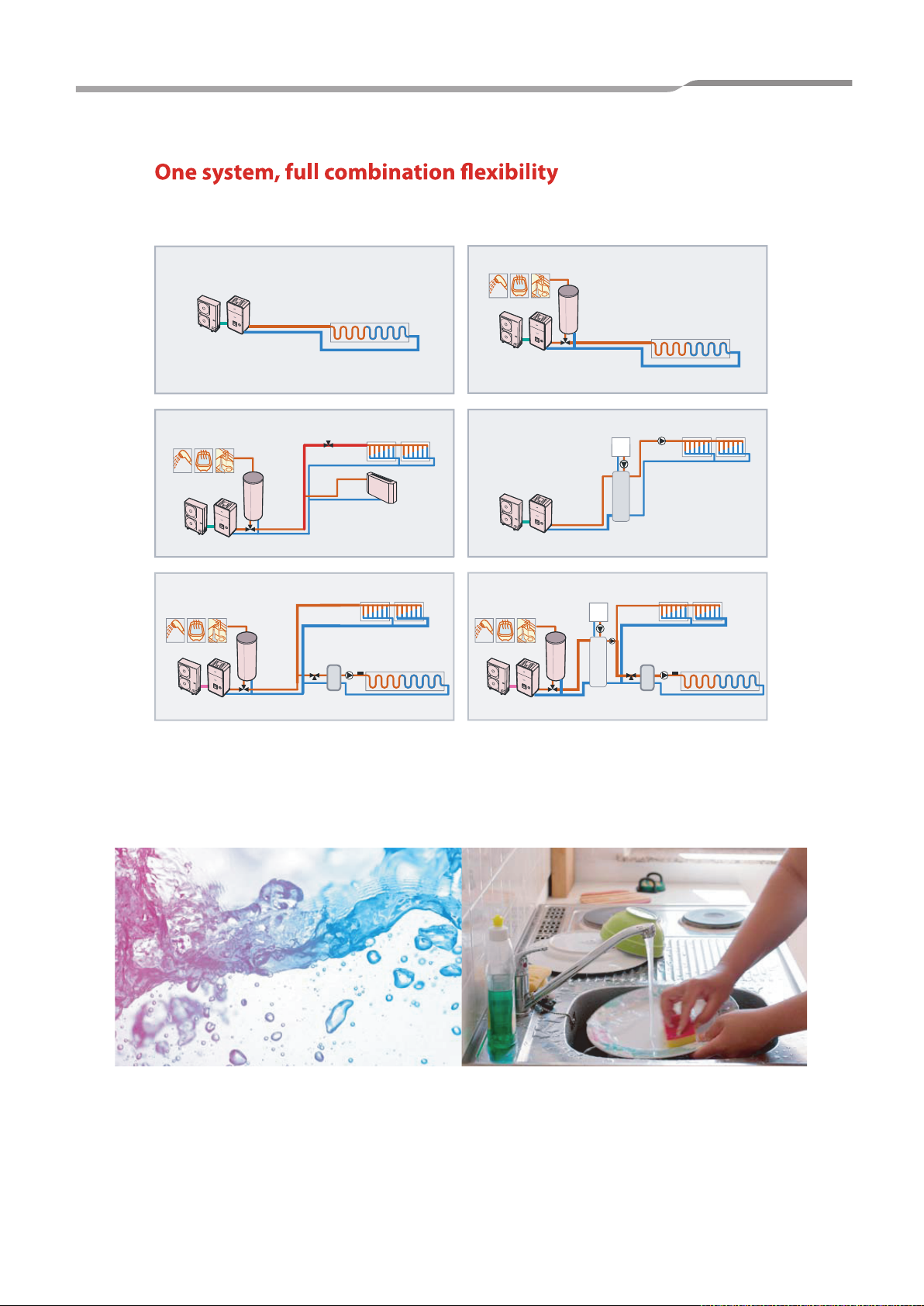
For new houses or refurbishment Estía heat pump offers a variety of combinations, some examples are shown below:
Engineering Data book
Outdoor unit
Shower Bath Kitchen
Hydro unit
Outdoor unit
Shower Bath Kitchen
Hydro unit
Outdoor unit
Hydro unit
Floor heating
2 way valve
Hot water
tank
1 zone heating / cooling with domestic hot water
Hot water
tank
Buffer tank
Mixing
valve
Buffer
tank
2 zone heating with domestic hot water
1 zone heating
HEATING ONLY
Panel radiator
Fan coil
Panel radiator
1 zone
1 zone
HEATING
COOLING
2 zones
Floor heatingTemp. sensor
Shower Bath Kitchen
Hydro unit
Outdoor unit
Outdoor unit
Shower Bath Kitchen
Hydro unit
Outdoor unit
1 zone
Hot water tank
1 zone heating with domestic hot water
Floor heating
1 zone
Hydro unit
Conventional boiler
Buffer
tank
1 zone heating with boiler backup
Panel radiator
2 zones
Conventional boiler
Hot water
tank
Mixing valve
2 zone heating with domestic hot water and boiler backup
Panel radiator
Floor heatingTemp. sensor
Buffer tank
I
n existing dwellings already equipped with traditional gas or
fuel boilers, Toshiba Estía air to water heat pump system can be
combined with the existing heating system to cover exclusively
and in an optimized way all the heating needs, all year round.
Then, the boiler is only used as a back-up source during some
extreme weather days of the winter.
T
he intelligent Toshiba control balances the energy source in the
most efficient way.
5
Page 7

2. SYSTEM OVERVIEW
6
Page 8
2.SYSTEM OVERVIEW
Engineering Data book
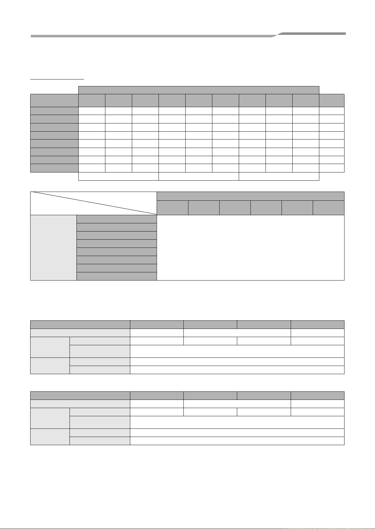
2-1. System Combination
Combination
Outdoor Unit
Hydro Unit
HWS-803XWHM3-E z ––––––––~, 3kW
HWS-803XWHT6-E z ––––––––3N ~, 6kW
HWS-803XWHD6-E z ––––––––3~, 6kW
HWS-803XWHT9-E z –– –––––3N~, 9kW
HWS-1403XWHM3-E – zzzzzzzz~, 3kW
HWS-1403XWHT6-E – zzzzzzzz3N~, 6kW
HWS-1403XWHD6-E – zz ––––––3~, 6kW
HWS-1403XWHT9-E – zzzzzzzz3N~, 9kW
Hydro unit
HWS-
803H-E
HWS-803XWHM3-E
HWS-803XWHT6-E
HWS-803XWHD6-E
HWS-803XWHT9-E
HWS-1403XWHM3-E
HWS-1403XWHT6-E
HWS-1403XWHD6-E
HWS-1403XWHT9-E
HWS-
1103H-E
Single phase model 3 phase model 3 phase with bottom plate heater
HWS-
1403H-E
HWS-
1103H8-E
HWS-
1403H8-E
HWS-
1603H8-E
HWS-
1103H8R-E
HWS-
1403H8R-E
HWS-
1603H8R-E
Hot water cylinder
HWS-1501
CSHM3-E
HWS-2101
CSHM3-E
HWS-3001
CSHM3-E
HWS-1501
CSHM3-UK
HWS-2101
CSHM3-UK
z
Backup
heater
HWS-3001
CSHM3-UK
2-2. Hydro Unit
80 class
Hydro Unit HWS-803XWHM3-E HWS-803XWHT6-E
Back up heater capacity 3.0 6.0 9.0
for back up heater 220-230V ~ 50Hz 380-400V 3N~ 50Hz 220-230V 3~ 50Hz 380-400V 3N~ 50Hz
Power supply
Leaving water
temperature
for hot water cylinder heater
(option)
Heating (°C) 20-55
Cooling (°C) 10-25
220-230V ~ 50Hz
112,140,160 class
Hydro Unit HWS-1403XWHM3-E HWS-1403XWHT6-E
Back up heater capacity 3.0 6.0 9.0
for back up heater 220-230V ~ 50Hz 380-400V 3N~ 50Hz 220-230V 3~ 50Hz 380-400V 3N~ 50Hz
Power supply
Leaving water
temperature
for hot water cylinder heater
(option)
Heating (°C) 20-55
Cooling (°C) 10-25
220-230V ~ 50Hz
HWS-803XWHD6-E
HWS-1403XWHD6-E
HWS-803XWHT9-E
HWS-1403XWHT9-E
7
Page 9
2.SYSTEM OVERVIEW
Engineering Data book
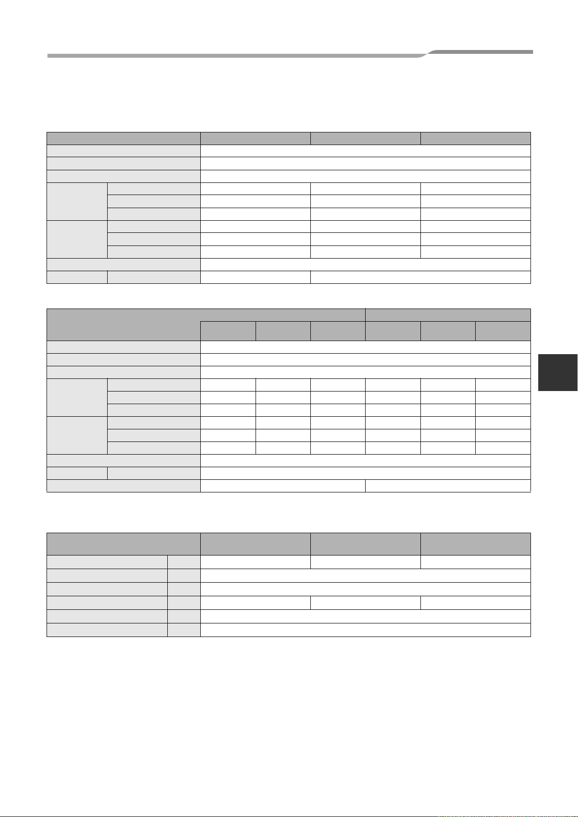
2-3. Outdoor Unit
Single Phase model
Outdoor unit HWS-803H-E HWS-1103H-E HWS-1403H-E
Power supply 220-230V ~ 50Hz
Type INVERTER
Function Heating & Cooling
Capacity (kW) 8.0 11.2 14.0
Heating
Cooling
Refrigerant R410A
Dimension HxWxD (mm) 890x900x320 1,340x900x320
3 Phase model
Power supply 380-400V 3N~ 50Hz
Type INVERTER
Function Heating & Cooling
Heating
Cooling
Refrigerant R410A
Dimension HxWxD (mm) 1,340x900x320
Bottom plate heater (W) – 75
Input (kW) 1.82 2.35 3.11
COP (W/W) 4.40 4.77 4.50
Capacity (kW) 6.0 10.0 11.0
Input (kW) 2.13 3.52 4.08
EER (W/W) 2.82 2.84 2.70
with bottom plate heater
Outdoor unit
Capacity (kW) 11.2 14.0 16.0 11.2 14.0 16.0
Input (kW) 2.39 3.21 3.72 2.39 3.21 3.72
COP 4.69 4.36 4.30 4.69 4.36 4.30
Capacity (kW) 10.0 11.0 13.0 10.0 11.0 13.0
Input (kW) 3.52 4.08 4.80 3.52 4.08 4.80
EER 2.84 2.70 2.71 2.84 2.70 2.71
HWS-
1103H8-E
HWS-
1403H8-E
HWS-
1603H8-E
HWS-
1103H8R-E
1403H8R-E
HWS-
HWS-
1603H8R-E
2
2-4. Hot Water Cylinder
Hot water cylinder (option)
HWS-1501CSHM3-E
HWS-1501CSHM3-UK
Water volume litres 150 210 300
Max water temperature (°C) 75
Electric heater (kW) 2.75 (230 V ~)
Height (mm) 1,090 1,474 2,040
Diameter (mm) 550
Material Stainless steel
8
HWS-2101CSHM3-E
HWS-2101CSHM3-UK
HWS-3001CSHM3-E
HWS-3001CSHM3-UK
Page 10

2.SYSTEM OVERVIEW
Engineering Data book
2-5. Options
No. Part name Model name Application Remarks
1 External output board TCB-PCIN3E
2 External input board TCB-PCMO3E
Second Remote
3
Controller
HWS-AMS11E
Boiler-linked output, Alarm output
Defrost signal output, compressor operation signal
output
Cooling/heating thermostat input
Forced-stop signal input
Wired Remote Controller for Room air temperature
control
Up to two boards (according
to applications)
Up to two boards (according
to applications)
9
Page 11

3. SYSTEM SPECIFICATION
10
Page 12
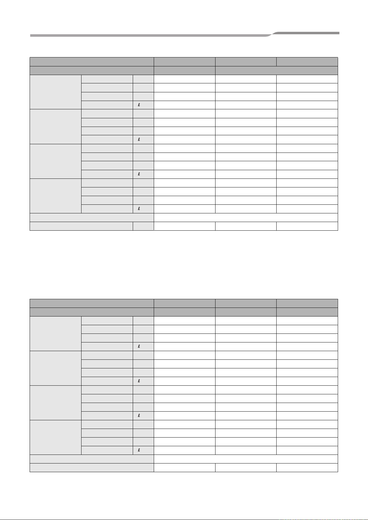
3.SYSTEM SPECIFICATION
Outdoor unit HWS-803H-E HWS-1103H-E HWS-1403H-E
Hydro unit HWS-803XWH**-E HWS-1403XWH**-E
Rated Heating
condition 1
LWT=35°C
dT=5deg
Rated Heating
condition 2
LWT=45°C
dT=5deg
Rated Cooling
condition 1
LWT=7°C
dT=5deg
Rated Cooling
condition 2
LWT=18°C
dT=5deg
Power supply 1~ 230V 50Hz
Maximum current A 19.2 22.8 22.8
Capacity kW 8.0 11.2 14.0
Power input kW 1.82 2.35 3.11
COP W/W 4.40 4.77 4.50
Rated water flow /min 22.9 32.11 40.13
Capacity kW 8.0 11.2 14.0
Power input kW 2.40 2.95 3.95
COP W/W 3.33 3.80 3.54
Rated water flow /min 22.9 32.11 40.13
Capacity kW 6.0 10.0 11.0
Power input kW 2.13 3.52 4.08
EER W/W 2.82 2.84 2.70
Rated water flow rate /min 17.2 28.67 31.53
Capacity kW 6.0 10 11.0
Power input kW 1.42 2.35 2.65
EER W/W 4.23 4.26 4.15
Rated water flow /min 17.2 28.67 31.53
Engineering Data book
* Rated condition capacity and power input are the data at rated compressor operating frequency.
* Power input does not include water pump power.
* Capacity and power input are measured in accordance with EN14511.
TO : Outdoor temperature (°C)
LWT : Leaving water temperature (°C)
dT : Delta temperature (deg)
Leaving water temperature - return water temperature (Heating)
Return water temperature - leaving water temperature (Cooling)
Outdoor unit HWS-1103H8-E HWS-1403H8-E HWS-1603H8-E
Hydro unit HWS-1403XWH**-E HWS-1403XWH**-E HWS-1403XWH**-E
Rated Heating
condition 1
LWT=35°C
dT=5deg
Rated Heating
condition 2
LWT=45°C
dT=5deg
Rated Cooling
condition 1
LWT=7°C
dT=5deg
Rated Cooling
condition 2
LWT=18°C
dT=5deg
Power supply 3N ~ 380-400V 50Hz
Maximum current 14.6 14.6 14.6
Capacity kW 11.2 14.0 16.0
Power input kW 2.39 3.21 3.72
COP W/W 4.69 4.36 4.30
Rated water flow rate /min 32.11 40.13 45.70
Capacity kW 11.2 14.0 16.0
Power input kW 3.19 4.12 4.88
COP W/W 3.51 3.40 3.28
Rated water flow rate /min 32.11 40.13 45.70
Capacity kW 10.0 11.0 13.0
Power input kW 3.52 4.08 4.80
EER W/W 2.84 2.70 2.71
Rated water flow rate /min 28.67 31.53 37.20
Capacity kW 10.0 11.0 13.0
Power input kW 2.14 2.43 3.08
EER W/W 4.67 4.53 4.22
Rated water flow rate /min 28.67 31.53 37.20
11
Page 13

4.HYDRO UNIT
4. HYDRO UNIT
4-1. Specification
4-1-1. Hydro unit specifications
Hydro unit HWS-803XWHM3-E HWS-803XWHT6-E HWS-803XWHD6-E HWS-803XWHT9-E
back up heater kW3669
Back up heater
Hot water
cylinder heater*
Appearance
Outer dimension
Unit weight kg 50
Packing
dimension
Total weight Unit and packing kg 54
Heat exchanger
Water pump
Expansion
vessel
Pressure relief
valve
Sound pressure level dBA 29
Operation water
temp.
Water pipe
Refrigerant pipe
Drain port mm 16.0 inner diameter for drain hose
Note
Power supply 1 ~ 220-230V 50Hz 3N~ 380-400V 50Hz 3~ 220-230V 50Hz 3N~ 380-400V 50Hz
Maximum current A 13 13 (13A*2P) 23A 13 (13A*3P)
Power supply 1 ~ 220-230V 50Hz
Maximum current A 12.0
Color Silky shade (Muncel 1Y8.5-0.5)
Material PCM
Height mm 925
Width mm 525
Depth mm 355
Height mm 1070
Width mm 608
Depth mm 436
Type Brazed plate
Water volume litres 0.67
Minimum flow rate /min 13
Power input W 125 / 95 / 65
Delivery head m 6.5 / 6.1 / 4.5
Volume litres 12
Initial pressure MPa(bar) 0.1 (1)
Operating pressure MPa(bar) 0.3 (3)
Heating °C 20~55
Cooling °C 10~25
Outlet mm 34.92
Inlet mm 34.92
Gas mm 15.9
Liquid mm 9.5
* The electric heater, incorporated in the hot water cylinder, requires separete supply
to hydro unit.
Engineering Data book
4
12
Page 14

4.HYDRO UNIT
Engineering Data book
Hydro unit
back up heater kW3669
Back up heater
Hot water
cylinder heater*
Appearance
Outer dimension
Unit weight kg 54
Packing
dimension
Total weight Unit and packing kg 58
Heat exchanger
Water pump
Expansion
vessel
Pressure relief
valve
Sound pressure level dBA 29
Operation water
temp.
Water pipe
Refrigerant pipe
Drain port mm 16.0 inner diameter for drain hose
Note
Power supply 1 ~ 220-230V 50Hz 3N~ 380-400V 50Hz 3~ 220-230V 50Hz 3N~ 380-400V 50Hz
Maximum current A 13 13 (13A*2P) 13 (13A*2P) 13 (13A*3P)
Power supply 1 ~ 220-230V 50Hz
Maximum current A 12.0
Color Silky shade (Muncel 1Y8.5-0.5)
Material PCM
Height mm 925
Width mm 525
Depth mm 355
Height mm 1070
Width mm 608
Depth mm 436
Type Brazed plate
Water volume litres 1.18
Minimum flow rate /min 17.5
Power input W 190 / 180 / 135
Delivery head m 8.3 / 8.1 / 7.2
Volume litres 12
Initial pressure MPa(bar) 0.1 (1)
Operating pressure MPa(bar) 0.3 (3)
Heating °C 20~55
Cooling °C 10~25
Outlet mm 34.92
Inlet mm 34.92
Gas mm 15.9
Liquid mm 9.5
HWS-1403XWHM3-E HWS-1403XWHT6-E HWS-1403XWHD6-E HWS-1403XWHT9-E
* The electric heater, incorporated in the hot water cylinder, requires separete supply
to hydro unit.
13
Page 15
4.HYDRO UNIT
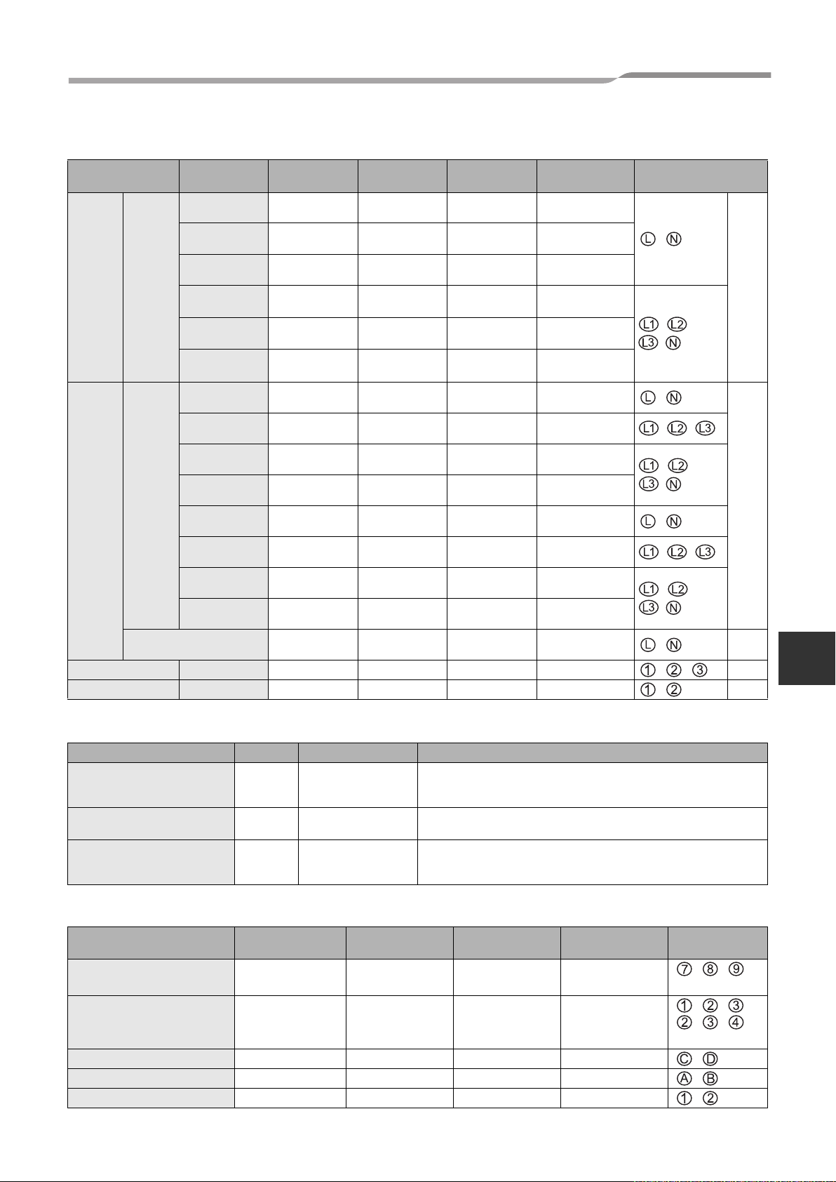
4-1-2. Power Wiring specifications
Engineering Data book
Description
Outdoor
unit
power
Hydro
inlet
heater
power
Outdoor-Hydro unit Connection 1.5 mm² or more , ,
Hydro -Cylinder Connection 1.5 mm² or more , TB03
Power
input
Power
input for
backup
heater
Power input for cylinder
heater
Model name
HWS-
1403H-E
1103H-E
803H-E
1603H8-E,
1603H8R-E
1403H8-E,
1403H8R-E
1103H8-E,
1103H8R-E
1403XWHM3-E
1403XWHD6-E
1403XWHT6-E
1403XWHT9-E
803XWHM3-E
803XWHD6-E
803XWHT6-E
803XWHT9-E
POWER
SUPPLY
220-230 V ~
50 Hz
220-230 V ~
50 Hz
220-230 V ~
50 Hz
380-400V 3N~
50Hz
380-400V 3N~
50Hz
380-400V 3N~
50Hz
220-230V ~
50Hz
220-230V 3~
50Hz
380-400V 3N~
50Hz
380-400V 3N~
50Hz
220-230V ~
50Hz
220-230V 3~
50Hz
380-400V 3N~
50Hz
380-400V 3N~
50Hz
220-230V ~
50Hz
Maximum
current
22.8A 25 A 2.5 mm² or more
22.8A 25 A 2.5 mm² or more
19.2A 20A 2.5 mm² or more
14.6A 16A 2.5 mm² or more
14.6A 16A 2.5 mm² or more
14.6A 16A 2.5 mm² or more
13A 16A 1.5 mm² or more ,
23A 25A 2.5 mm² or more , ,
13A(13A x 2P) 16A 1.5 mm² or more
13A(13A x 3P) 16A 1.5 mm² or more
13A 16A 1.5 mm² or more
23A 25A 2.5 mm² or more
13A(13A x 2P) 16A 1.5 mm² or more
13A(13A x 3P) 16A 1.5 mm² or more
12A 16A 1.5 mm² or more
Installation
fuse rating
Power wire Connection destination
,
, ,
,
, ,
,
,
, ,
, ,
,
,
TB02
TB03
4
4-1-3. External Device specifications
Power Maximum current Type
Motorized 3-way valve
(for hot water)
Motorized 2-way valve
(for cooling)
Motorized mixing valve
type 1 (for 2-zone)
AC 230 V 100 mA
AC 230 V 100 mA spring return type (normally open)
AC 230 V 100 mA
Spring return type
Note: 3-wire SPST and SPDT type can be used by changing the
DPSW 13-1.
60 sec 90º. SPDT type
Note: SPST and 20 to 240 sec type can be used by changing the
function code.
4-1-4. External Device Wiring specifications
Description Line spec Maximum current Maximum length Cable size
3-way valve control 2 line or 3 line 100 mA 12 m 0.75 mm² or more
Mixing valve control 3 line 100 mA 12 m 0.75 mm² or more
2-zone thermo sensor 2 line 100 mA 5 m 0.75 mm² or more , (TB06)
Cylinder thermo sensor 2+GND(shield wire) 100 mA 5 m 0.75 mm² or more , (TB06)
Second remote controller 2 line 50 mA 50 m 0.75 mm² or more , (TB07)
Connection
destination
, ,
(TB05)
, , or
, ,
(TB04)
14
Page 16

4.HYDRO UNIT
4-1-5. External Output specifications
Engineering Data book
Description Output
External pump No.1 AC230V 1 A – 12 m
External boost heater AC230V 1 A – 12 m
Boiler control
ALARM Output
Compressor Operation Output
Defrost Output
Non-voltage
contacts
Non-voltage
contacts
Non-voltage
contacts
Non-voltage
contacts
Maximum
current
0.5 A AC230 V 12 m
1 A DC24 V 12 m
0.5 A AC230 V 12 m
1 A DC24 V 12 m
0.5 A AC230 V 12 m
1 A DC24 V 12 m
0.5 A AC230 V 12 m
1 A DC24 V 12 m
Max voltage
Maximum
length
Output as required when outdoor air
temperature is -20°C or less
Output as required when outdoor air
temperature is -10°C or less
4-1-6. External Input specifications
Description Input Maximum length
Emergency stop control Non-voltage 12 m
Cooling thermostat input Non-voltage 12 m
Heating thermostat input Non-voltage 12 m
15
Page 17
4.HYDRO UNIT
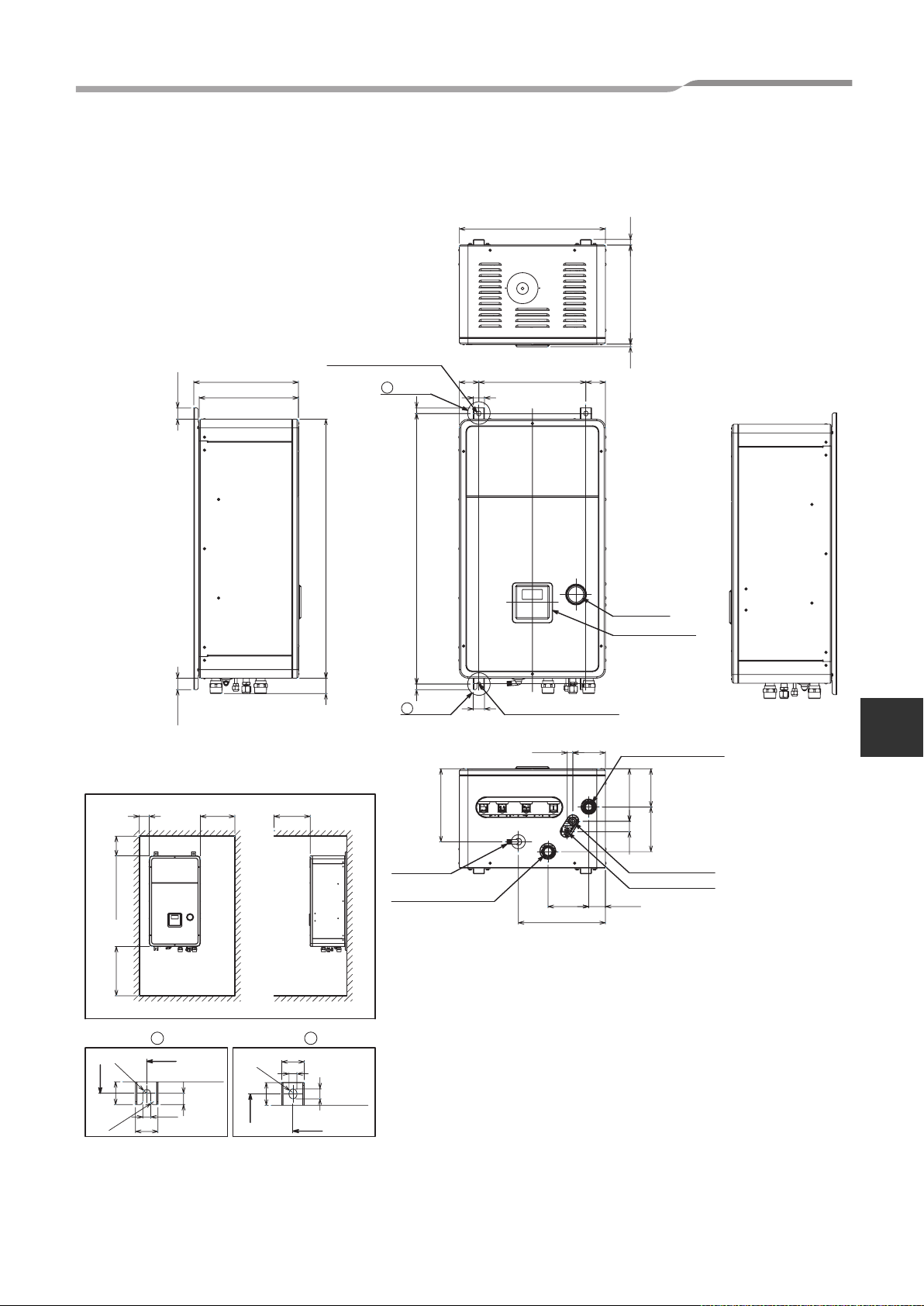
4-2. Dimension
▼Hydro unit
525
19.5
352
Engineering Data book
100 or more
200 or more
40.540.5
Service space
350 or more
371.5
355
500 or more
2-dia.12x17 long hole
(for dia.8-10 anchor bolt)
B leg part
2020
92554
960
A leg part
Drain nipple
Water inlet
connecting pipe 1 1/4"
72.5 72.5
40
Anchor bolt long hole pitch
40
259
380
Anchor bolt
long hole pitch
2-dia.12x17 U-shape hole
(for dia.8-10 anchor bolt)
309.5
Manometer
Remote controler
Hot water outlet
11619.5
connecting pipe 1 1/4"
59.5144.5
9
135.5
186.5
158
37.5
Gas line dia.15.88
Liquid line dia.9.52
4
500 or more
Detailed A leg part Detailed B leg part
960
R14
81
80
28
380
36
Outside line
of product
960
R14
81
2-R10
80
380
28
Outside line
of product
40
16
Page 18
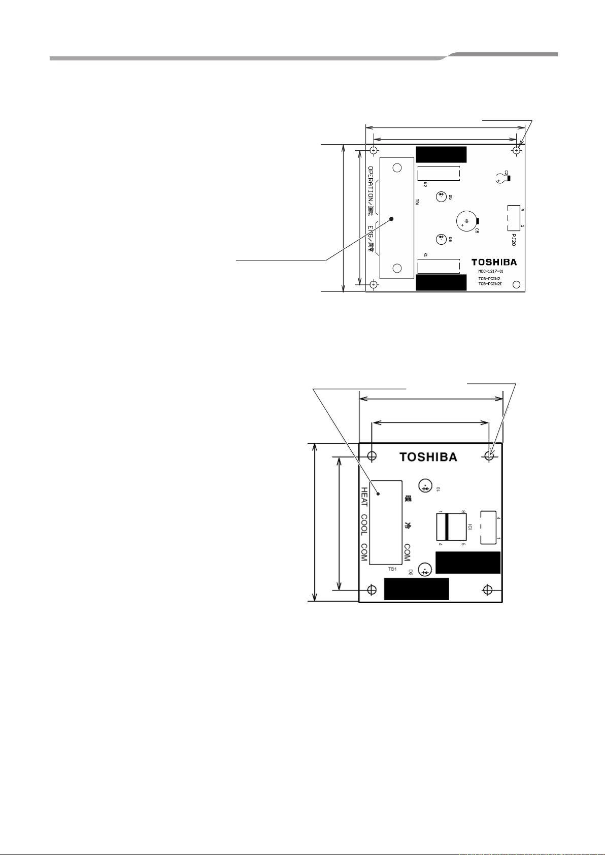
4.HYDRO UNIT
▼External output board (TCB-PCIN3E)
Engineering Data book
Size (mm) : H22 x L73 x W79
Weight (g) : 57
Terminal (Screw M3
▼External input board (TCB-PCMO3E)
Size (mm) : H18 x L55.5 x W60
Weight (g) : 20
63
73
)
Terminal (Screw M3)
79
69
55.5
4- 4Øhole
4-Ø4 hole
60
50
45.5
NCC-1214 TCB-PCMO2
TCB-PCMO2E
PJ17
17
Page 19
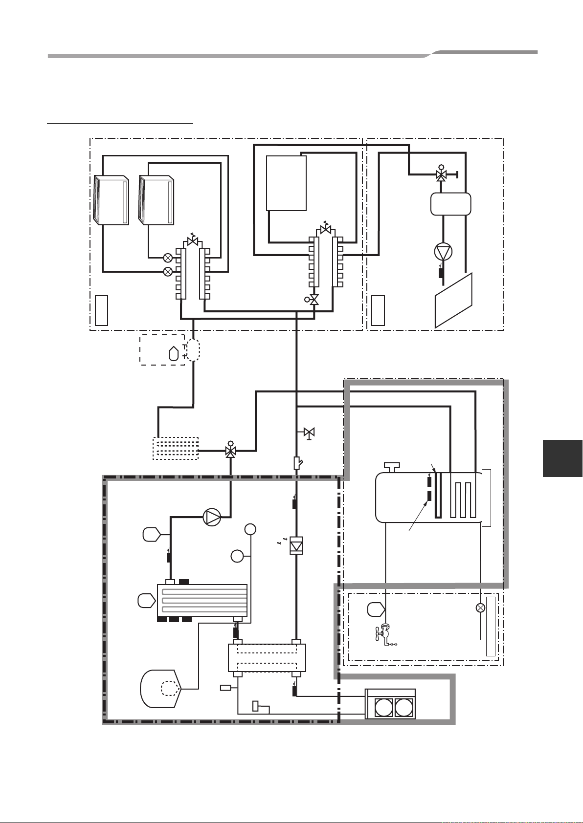
4.HYDRO UNIT
4-3. Piping Diagram
Water system diagram
Engineering Data book
M
Fan coil unit
zone1
Boiler
(locally
procured)
Booster heater
(locally procured)
By-pass valve
(locally procured)
AC230V
(locally procured)
Motorized 3-way valve
M
Radiator unit
2-way valve for
cooling mode
(locally procured)
AC230V
Strainer
40 mesh
(locally procured)
By-pass valve
(locally procured)
(locally procured)
Drain cock for water charge
Relief valve (UK)
zone2
10bar
90 °C
AC230V
(locally procured)
Moterized mixing valve
TFI
AC pump
(locally procured)
2.75kW
:
Ø1
Cylinder heater
TTW
Floor
heating
Buffer tank
(locally procured)
4
set : 3bar
Pressure relief valve
THO
Air vent valve
Expansion vessel
set : 1bar
AC pump
°C
(auto)
set : 75±3
Thermal protector
°C
set : 95±5
single operation
Thermal protector
Menometer
gage : ~6bar
TWO
Pressure sw
4.15MPa
Water vent valve
Flow sw
Backup heater
TWI
13 /min
17.5 /min
:
:
set
set
TC
Pressure sensor
Water heat exchanger
Water outlet
Pressure relief
°C
82+3-2
(manual reset)
Thermal cut-out
Outdoor unit
Hot water cylinder
Water inlet
Reducing valve
Local hot water system
18
Page 20
4.HYDRO UNIT
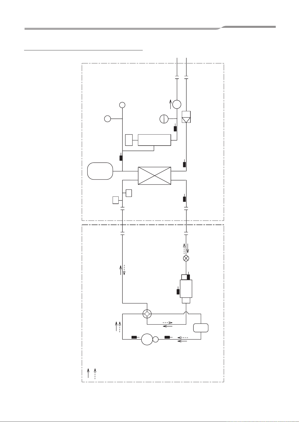
Refrigeration cycle system diagram
Water vent valve
Manometer
P
Circulating pump
Engineering Data book
Expansion vessel
TWO
Pressure Switch
Air vent valve
Backup heater
Low Pressure
sensor
THO
Safety valve
TWITC
heat exchanger
Pulse motor
valve
Flow switch
TE
Outdoor unit Hydro unit
Heating / Hot-water supply
Defrosting / Cooling
TD
4-way valve Plate-type water
Compressor
19
TS
TO
Outdoor heat
exchanger
Accumulator
Page 21
4.HYDRO UNIT
4-4. Wiring Diagram
4-4-1. Hydro unit
Remote
controller
(HWS-AMS11E)
AB
WHI
GRY
Color identification
BLU : BLUE
BLK : BLACK
GRN : GREEN
BRW : BROWN
ORN : ORANGE
GRY : GRAY
RED : RED
PNK : PINK
YEL : YELLOW
WHI : WHITE
WHI WHI
YEL
5251
WPM
*See DIP SW13_1
BLU
3
5
4
5
2WV
WHI
BRW
55
56
BH 3WV
(2-wire spring return)
(3-wire SPST type)
(3-wire SPDT type)
CN10
(WHI)
YEL
9
9
CR10
RY
787
6
55
4
3
2
11
3
3
11
CR11
CR12
CR13
CN01
(WHI)
2
F01 (5A)
10
RY
11
WHI
ORN
PNK
RED
4
3
44
41
2
4
MIXV
(3-wire SPDT type)
WHI
ORN
PNK
RED
43
4
4
41
42
MIXV
(3-wire SPST type)
RY
12
RY
13
Relay
p.c.board
(MCC-1431)
TB 04
Type 1
TB 04TB 05
Type 2
WPM
CN02
(WHI)
A2
RED
BLU
55
4
ORN
4334
3
GRN
2
BRW
2
2
1
11
BLK
BLU
BRW
LNNL
1
RED
WHI
RY
A1
1
05
YEL
7
WHI
5
RED
1
BLU
BRW
WHI
WHI
RED
RED
WHI
YEL
TB 05
5
8
59
5
7
Type 1
WHI
YEL
RED
59
57
8
5
3WV
Type 2
Type 3
controller
(HWS-AMS11E)
TB 07
6
515
4
CN501
(YEL)
3
2
313
CN603
(YEL)
313
CN601
(RED)
7
5
3
1
CN602
(WHI)
Remote
AB
A
7
GRY
1
1
CN41
(BLU)
PNK
*Option
7
B
2
1
2
1
WHI
3
2
3
CN604
(BLU)
2
ORN
BLK
BLK
2
1
2
1
CN203
(YEL)
RY601RY600RY603 RY602
5
3
7
5
3
7
WHI
RED
5
7
RY
06
468
RED
THOTWOTWITC
LPS
3
4
2
1
3
4
2
3
4
2
3
4
2
BLK
BLK
BLK
BLK
BLK
BLK
1
1
CN204
(BRW)
3
2
3
2
111
1
2
1
1
CN206
CN205
(WHI)
(RED)
P.C.board
(MCC-1511)
WHI
BLK
RED
3
2
2
2
22
3
1
CN207
CN212
(BLU)
(WHI)
1
SW01
SW02
ON
12 43
SW10 SW 11 SW12 SW13
ON
ON ON21ON
1234 1234 12341234
SW06
ON
SW07
RY607RY606RY605RY604
CN605
CN606
(YEL)
(BLU)
3
3
1
1
L
BLK
YE
RY
01
1
3
1
WHI
ORN
A2
6
RY
02
03
A1
7
4
WHI WHI
*
1
3
1
WHI
PNK
A1
648
RY04RY
A2
1
*Option
TTW
AB
6
C
D
A
6
6
B
6
BRW
BRW
RED
2
1
1
2
2
34
1
1
CN213
CN214
(WHI)
(WHI)
SW14
OFF
ON
CN305
CN100
(GRN)
(WHI)
5
3
3
1
33
WHI
GRY
TFI
TB 06
RED
3
3
1
2
CN208
(BLU)
3
414
1
2
CN209
(GRN)
3
414
1
2
CN210
(RED)
3
414
1
2
CN211
(BLK)
3
414
1
CN200
2
(RED)
33
CN201
11
(WHI)
22
11
CN202
(YEL)
1
2
CN102
3
(WHI)
4
5
6
CN101
(WHI)
11
33
F100
Fuse
T5A
P100
250V~
1
1
RED
1
HWS-803XWHT6-E : Installed
*
HWS-1403XWHT6-E : Installed
HWS-803XWHD6-E : Installed
HWS-1403XWHD6-E : Installed
HWS-803XWHT9-E : Installed
HWS-1403XWHT9-E : Installed
HWS-803XWHM3-E : Not installed
HWS-1403XWHM3-E : Not installed
Engineering Data book
*Option p.c.board
GRN
1
GRN
Relay
2
2
2
p.c.board
GRN
3
3
3
(MCC-1217)
GRN
414
PJ20
GRN
1
GRN
Relay
2
2
2
p.c.board
GRN
3
3
3
(MCC-1217)
GRN
414
PJ20
YEL
1
YEL
Photocoupler input
2
2
2
p.c.board
YEL
3
3
3
(MCC-1214)
YEL
414
PJ17
YEL
1
YEL
Photocoupler input
2
2
2
p.c.board
YEL
3
3
3
(MCC-1214)
YEL
414
PJ17
YEL
RY
8
7
1
01
GRN
2
RED
11
BLK
BLK
33
BLK
BLK
323
BRW
1
BRW
2
RED
3
RED
4
ORN
5
ORN
6
WHI
WHI
BLK
K1
K2
TB1
K1
K2
TB1
TB1
TB1
22
11
Pressure switch
4.15MPa
Thermal protector
(auto)
75 5
Transformer
4
3
2
1
4
3
2
1
3
2
1
3
2
1
Flow switch
Boiler control O/P
Alerm O/P
Compressor operation
O/P
Defrost O/P
Emergency stop I/P
Cooling thermostat I/P
Heating thermostat I/P
4
WHI
RED
GRY
TB 01
3
12
Power supply
220 - 230V~ 50Hz
or
380 - 400V~ 50Hz
TB 03
12111
Outdoor unit
3
BRW
BLU
12
33
12
Hot water cylinder
1L1
3L2
RY05
4T2
2T1
BLU
BRW
F1 F2
BLU
BRW
N
L
Power supply
220 - 230V~ 50Hz
F1, F2
Fuse
AC250V
T30A
YEL/GRN
*Option
5L3
1L1
3L2
RY02
4T2
6T3
2T1
GRY
BRW
BLU
F3F4F6F5F8
F7
BLU
BLK
BLU
BRW
L3
L1 L2
Power supply
380 - 400V 3N~ 50Hz
1L12L3
4T2
2T1
BLK
BLU
GRY
TB 02
N
Thermal protector
(Single operation)
95 5
Thermal protector
(Single operation)
95 5
Thermal protector
(Single operation)95 5
5L3
RY04
6T3
BLU
BLU
F3~8
Fuse
AC250V
T30A
HWS-803XWHT9-E
HWS-1403XWHT9-E
Backup heater 1
Backup heater 2
Backup heater 3
RY02
4T22T1 6T3
BLU
BRW
F5
F3 F6
F4
BLK
BLU
BRW
Power supply
380 - 400V 3N~ 50Hz
1L1 3L2
3L51L12L3
2T1 4T2
BLK
BLU
L3
1L2L
Thermal protector
(Single operation)
95 5
Thermal protector
(Single operation)
95 5
5L3
RY04
6T3
BLU
F3~6
Fuse
AC250V
T30A
TB 02
N
HWS-803XWHT6-E
HWS-1403XWHT6-E
Backup heater 1
Backup heater 2
Thermal protector
(Single operation)
5L31L1 3L2
6T32T1 4T2
BLU
BRW
F3
F4
F3,F4
Fuse
AC250V
T30A
BLU
BRW
LN
Power supply
220 - 230V~ 50Hz
95 5
RY02
TB 02
HWS-803XWHM3-E
HWS-1403XWHM3-E
Backup heater 1
4T22T1 6T3
BLU
BRW
F5
F3 F6
F4
BLU
BRW
Power supply
220 - 230V 3~ 50Hz
RY02
BLK
3L51L12L3
BLK
BLU
1L2L
Thermal protector
(Single operation)
95 5
Thermal protector
(Single operation)
95 5
1L1 3L2
2T1 4T2
F3~6
Fuse
AC250V
T30A
TB 02
L3
5L3
6T3
BLU
Backup heater 1
Backup heater 2
RY04
HWS-803XWHD6-E
HWS-1403XWHD6-E
Symbol Parts name Symbol Parts name
WPM Water pump motor TC Water heat exchanger temperature sensor
3WV 3-way valve (locally procured) TWI Water inlet temperature sensor
2WV 2-way valve (locally procured) TWO Water outlet temperature sensor
MIXV Mixing valve (locally procured) THO Heater outlet temperature sensor
BH Booster heater TTW Hot water cylinder temperature sensor
RY01~RY06 Relay01~Relay06 TFI Floor heating inlet temperature sensor
LPS Low pressure sensor TB Terminal block
Backup heater1, 2, 3 Heater AC230V, 3kW
1. The one-dot chain line indicates wiring at the local site, and the dashed line indicates accessories sold separately and service wires,
respectively.
2. , and indicates the terminal board and the numberals indicate the terminal numbers.
3. indicates P.C. board.
* Be sure to fix the electric parts cover surely with screws. (Otherwise water enters into the box resulting in malfunction.)
20
Page 22
4.HYDRO UNIT
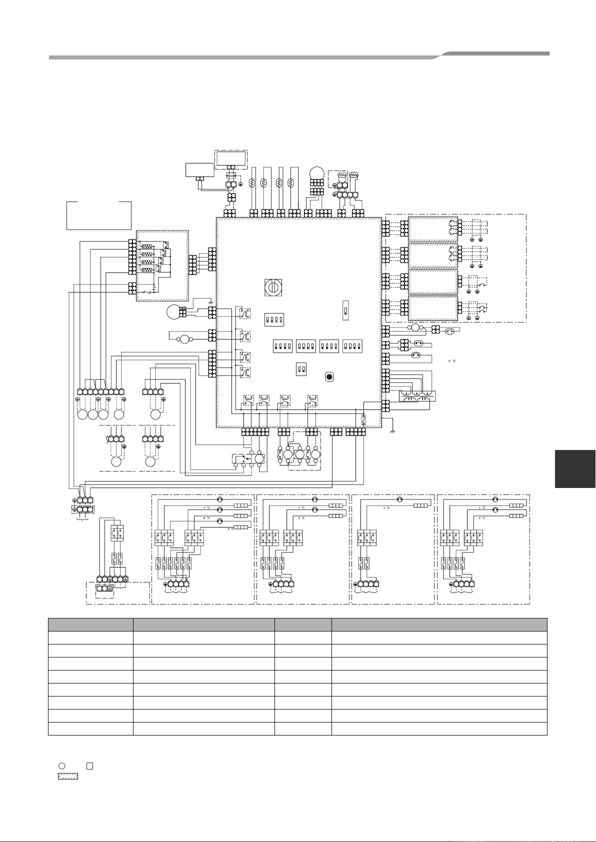
4-4-2. Power line
Electrical connection to hydro unit
Engineering Data book
Backup heater
220-230V ~ type
(3kW type)
Input power
220-230V 50Hz
Leakage
breaker 30mA
Backup heater
380-400V 3N~ type
(6,9kW type)
Input power
220-230V
3N~ 50Hz
Leakage
breaker 30mA
Backup heater
220-230V 3~ type
breaker 30mA
L N L1 L2 L3 N L1 L2 L3
Outdoor unit to hydro unit electrical connection
(6kW type)
Input power
220-230V
3~ 50Hz
Leakage
TB 20TB02TB02
Hot water cylinder
1
2
Input power
220-230V~ 50Hz
Input power
380-400V
3N~ 50Hz
Leakage breaker
30mA
Leakage breaker
30mA
L1
L2
L3
1
TB01
TB03
2
Leakage
L
N
breaker 30
mA
Input power for
cylinder heater
230 V ~ 50 Hz
1
2
L
N
3
1
2
N
3
Hydro unitOutdoor
unit
1
2
3
1
2
TB01
3
21
Page 23
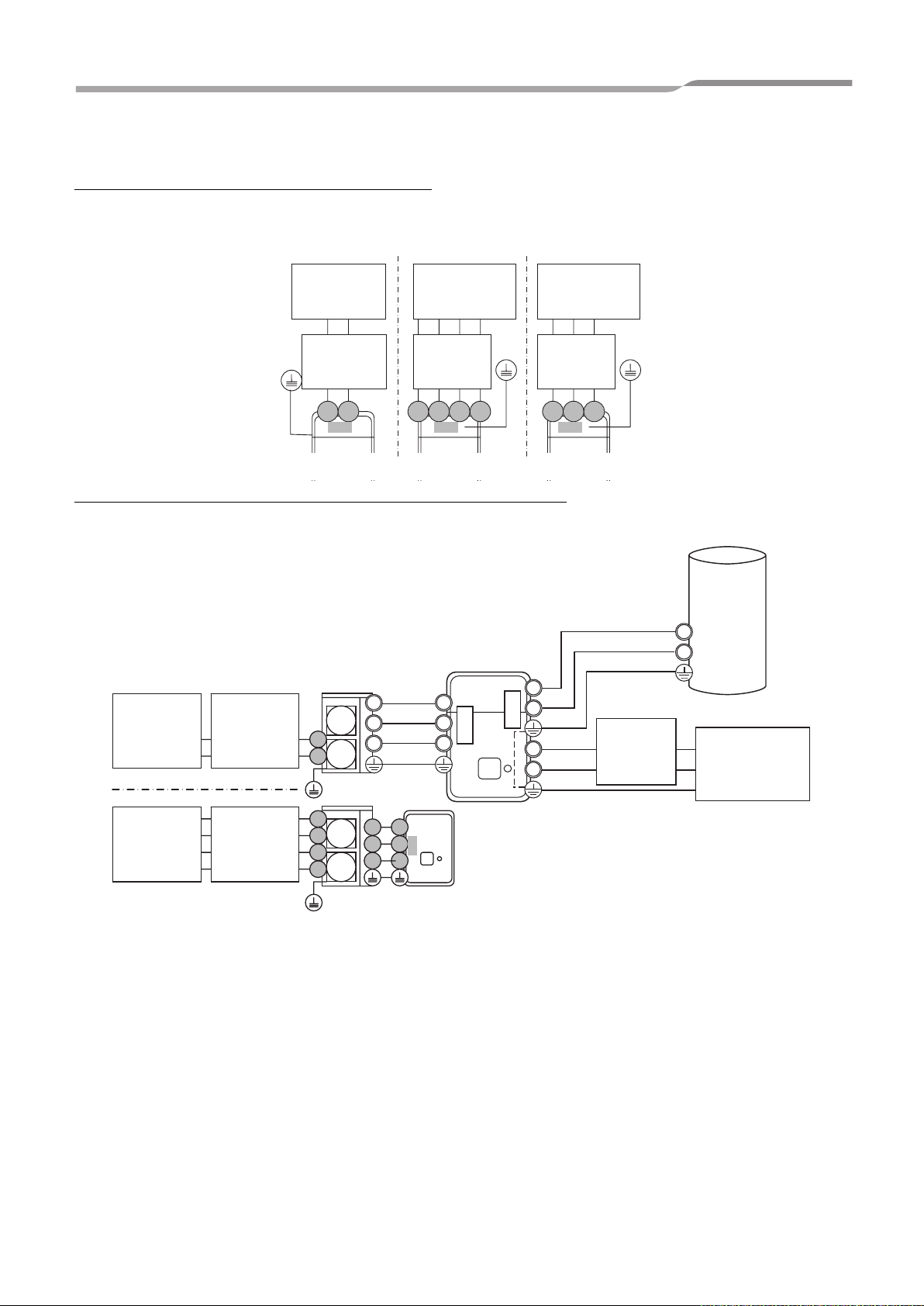
4.HYDRO UNIT
Engineering Data book
55
53
51
52
WPM
TB 05
565758
54
BH
2WV
TB03
Don't apply
6B6A 6D
6C
TB 06
220-240V
TF1
or
breakdown
will occur.
TTW
TB01
to Outdoor unit
Sensor
connection
Outdoor unit
connection
4-4-3. Control line
3WV
1
11 12
TB 01
59
3
2
13
43
41
Hot
water
cylinder
44
42
MIXV
TB 04
31 32
HOT WATER CYLINDER
L
TB 03
Input power
220-230 V ~
50 Hz
Hot water cylinder
power supply
Mixing-Valve
type 2 for 2 zone
control
TB02
L3
N
L2L1
N
L
N
TB 02
Input power
220-230 V ~
50 Hz
Backup heater
power supply
Mixing-Valve type 1
for 2 zone control
Input power
380-400 V 3N
~ 50 Hz
L1 L2
L3
N
L1 L2
Input power
220-230 V
3 ~ 50 Hz
L3
Pump (local)
Max 12 m
230 V 100 mA
0.75 mm² or more
Booster heater
(local)
Max 12 m
230 V 1 A
0.75 mm² or more
2Way-Valve for
cooling stop
Max 12 m
230 V 1 A
0.75 mm² or more
3Way-Valve for hot
water cylinder
Alert output
(local)
4
2
3
1
TB04
1
2
3
4
TB05
5
6
7
8
CN208
OPTION OPTION
9
PJ20
2
1
Boiler operation
(local)
4
3
Max 12 m
230 V 100 mA
0.75 mm² or more
N
CW
4
2
3
1
Max 5 m shielded wire
0.75 mm² or more
CCW
A
B
Temp sensor in hot
water cylinder
A
B
4
TB06
TB07
1
2
CN209
C
D
Temp sensor for
2 zone control
Max 50 m shielded wire
0.75 mm² or more
Max 5 m shielded
wire 0.75 mm² or
more
PJ20
2
1
3
2nd Remote control
4
Max 12 m non
voltage 0.75 mm² or
more
Defrost output
(local)
Compressor
operation output
(local)
22
Page 24
4.HYDRO UNIT
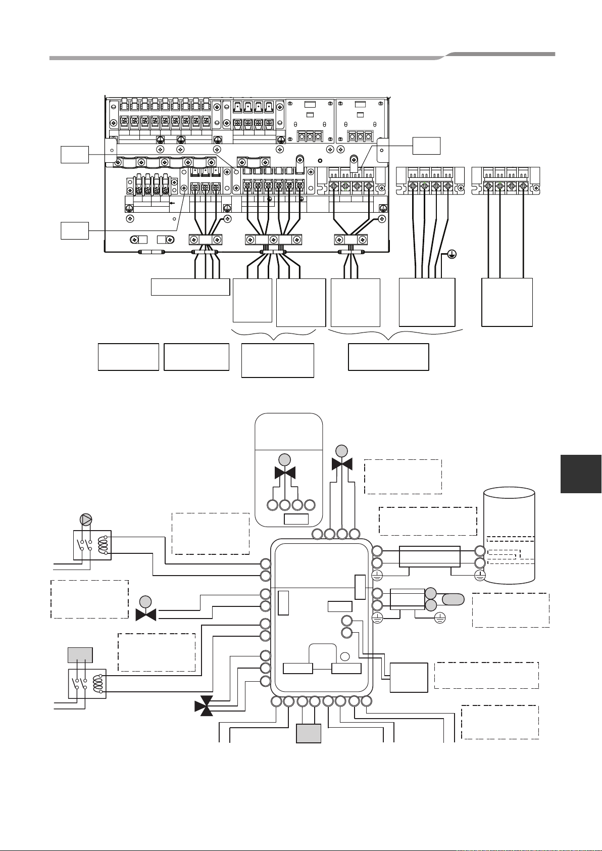
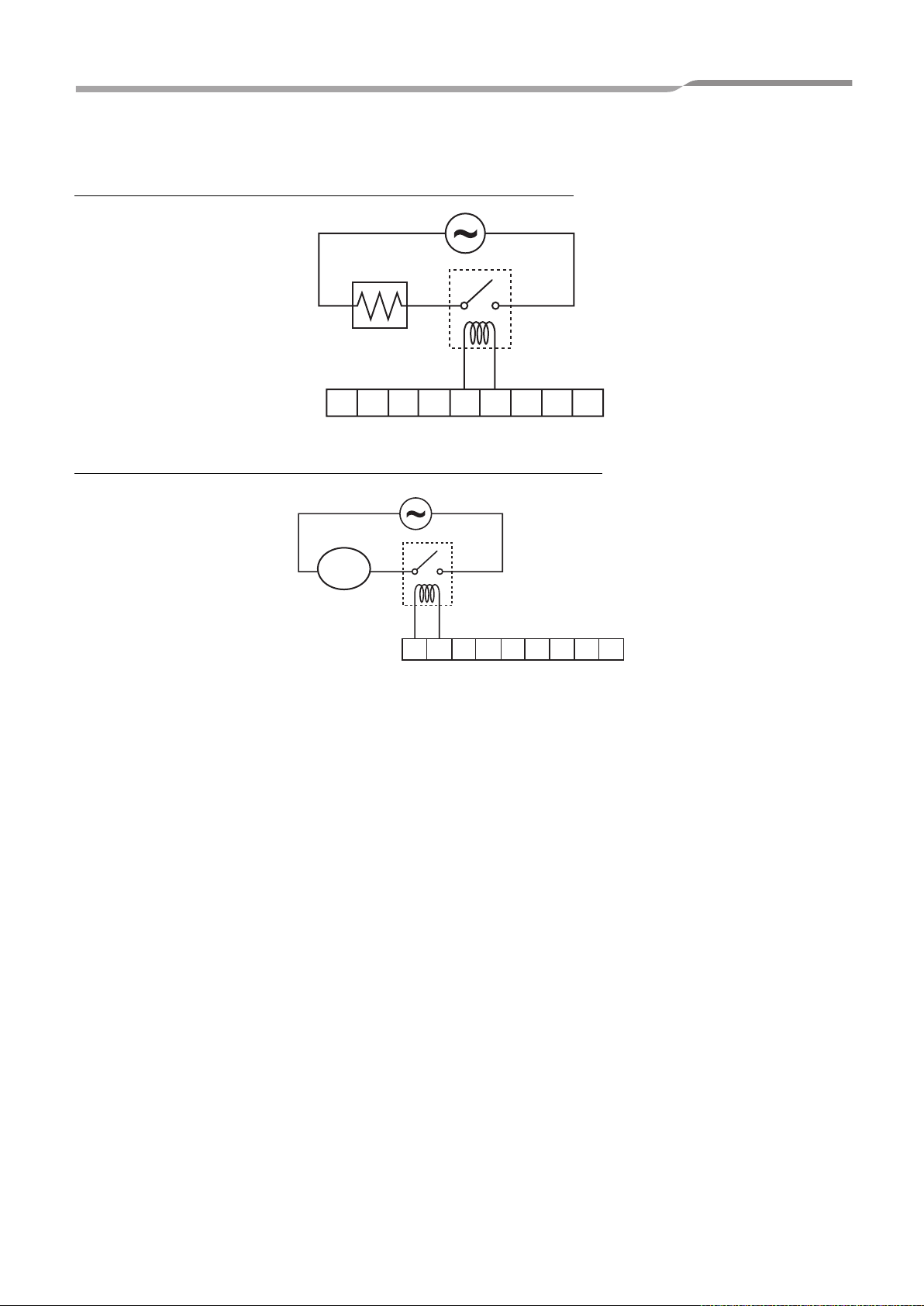
4-4-4. External Device
Electrical connection for external booster heater
Booster Heater
Engineering Data book
1234567 8 9
Electrical connection for external additional pumps
Pump
01
1234567 8 9
Terminal Block 05
Terminal Block 05
23
Page 25
4.HYDRO UNIT
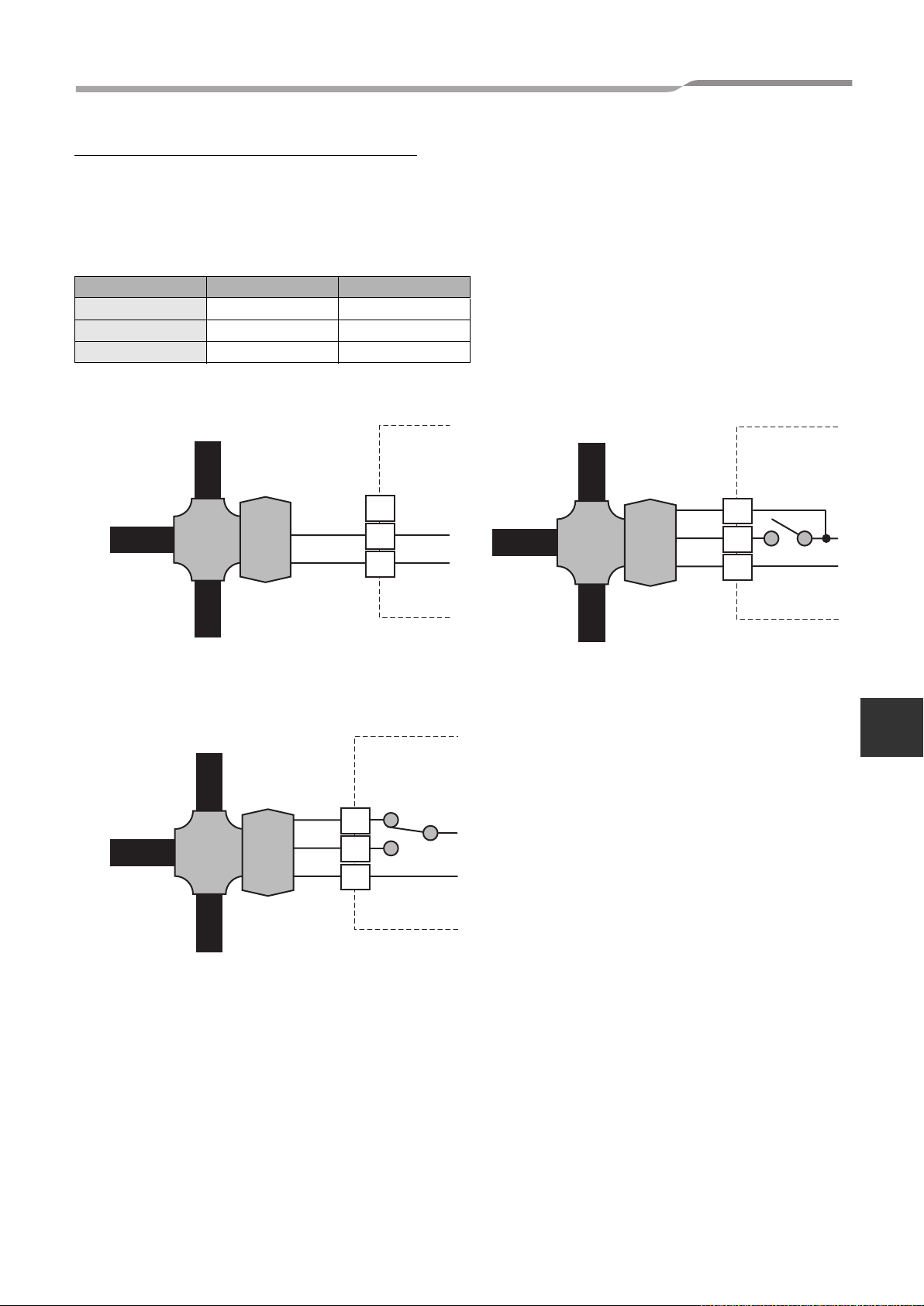
3-way valve (diverter) connection
Required Valve Specification:
Electrical Specification: 230 V; 50 Hz; <100 mA
Valve Diameters: Port A, Port B: Ø 1 1/4"
Return Mechanism: 3 types of 3-way valve (diverter) can be used.
Set the 3-way valve in use with the DIP switch SW13-1 on the Hydro Unit board.
SW13-1
Type 1 2-wire spring return OFF
Type 2 3-wire SPST OFF
Type 3 3-wire SPDT ON
Type 1: SPRING RETURN Type 2: SPST
port “A” to Hot water
cylinder
Hydro Unit
port “A” to Hot water
cylinder
Engineering Data book
Hydro Unit
port “AB” to
Hydro unit
Type 3: SPDT
port “AB” to
Hydro unit
port “A” open
port “B” to Room heating or
cooling
port “A” to Hot water
cylinder
port “A”
close
open
TB 05
7
8
9
Hydro Unit
TB 05
7
8
9
port “AB” to
Hydro unit
port “A”
close
open
port “B” to Room heating or
cooling
TB 05
7
8
9
4
port “B” to Room heating or
cooling
24
Page 26
4.HYDRO UNIT
Engineering Data book
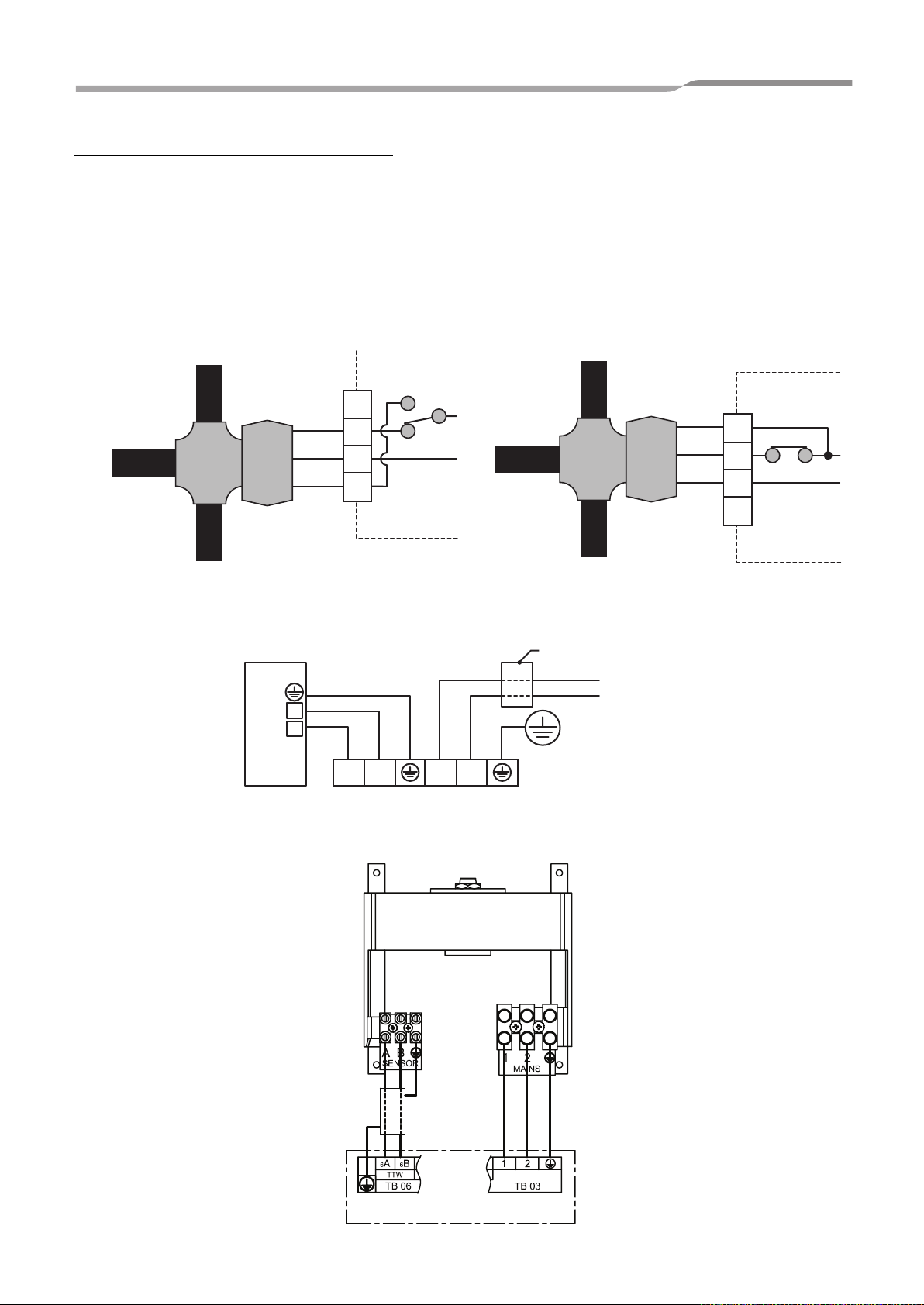
3-way mixing valve connection
Required Actuator Specification
Electrical Specification:230 V; 50 Hz; <100 mA
The 3-way mixing valve is used to achieve the temperature differential needed in a 2-zone heating system.
• Connect the 3-way mixing valve to terminals 2, 3 and 4 on Terminal Block 04 (for Type 1 mixing valve) or on
terminals 1, 2 and 3 on Terminal Block 04 (for Type 2 mixing valve).
• Connect the 3-way mixing valve in accordance with the diagrams below:-
Type 1: SPDT Type 2: SPST
port “A” to Zone 2 Heating
port “AB” to
Hydro unit
open
Hydro Unit
TB 04
1
2
3
port “A”
close
port “B” BLANK OFF
4
Hot water cylinder connection (optional)
2
1
12 LN
Hot water cylinder
port “A” to Zone 2 Heating
port “AB” to
Hydro unit
port “B” BLANK OFF
Earth leakage breaker
INPUT Power 230 V ~ 50 Hz
Terminal block 03
port “A”
close
open
Hydro Unit
TB 04
1
2
3
4
Hot water cylinder electrical box connections
Hydro unit
25
Page 27

4.HYDRO UNIT
4-5. Capacity Tables
▼Outdoor unit HWS-803H-E
Hydro unit HWS-803XWH**-E
Rated heating capacity and power input
Capacity kW 8.0
Rated condition 1
LWT=35°C
dT=5deg
Rated condition 2
LWT=45°C
dT=5deg
* Rated heating capacity and power input are the data at rated compressor operating frequency
* Power input does not include water pump power.
* Heating capacity and power input are measured in accordance with EN14511.
TO : Outdoor temperature (DB°C) RH85%
LWT : Leaving water temperature (°C)
dT : Delta temperature (deg)
Leaving water temperature - return water temperature
Power input kW 1.82
COP W/W 4.40
Rated water flow rate /min 22.9
Capacity kW 8.0
Power input kW 2.40
COP W/W 3.33
Rated water flow rate /min 22.9
Engineering Data book
4
26
Page 28

4.HYDRO UNIT
Average heating capacity and power input
Engineering Data book
Capacity (kW)
TO
(°C)
Power input (kW)
TO
(°C)
LWT (°C)
30 35 40 45 50 55
-20 3.93 3.83 3.74 — — —
-154.664.544.444.27— —
-7 5.45 5.30 5.15 4.99 4.84 —
-2 6.24 6.11 5.97 5.84 5.69 5.55
2 6.86 6.75 6.64 6.52 6.47 6.38
7 9.02 8.78 8.58 8.34 8.11 7.87
10 9.56 9.29 9.10 8.84 8.42 8.29
12 10.11 9.81 9.62 9.35 8.92 8.87
15 10.94 10.60 10.41 10.13 9.68 9.52
20 12.42 11.99 11.82 11.50 11.03 10.78
LWT (°C)
30 35 40 45 50 55
-20 1.70 1.82 1.90 — — —
-151.781.902.002.13— —
-7 2.06 2.21 2.33 2.47 2.79 —
-2 2.10 2.26 2.39 2.56 2.86 3.14
2 2.11 2.28 2.43 2.60 2.88 3.17
7 1.87 2.07 2.25 2.46 2.65 2.85
10 1.84 2.03 2.21 2.42 2.61 2.86
12 1.83 2.02 2.20 2.41 2.60 2.87
15 1.83 2.02 2.20 2.41 2.60 2.88
20 1.82 2.01 2.18 2.44 2.58 2.91
COP
TO
(°C)
30 35 40 45 50 55
-20 2.32 2.11 1.97 — — —
-152.622.382.222.00— —
-7 2.64 2.40 2.21 2.02 1.73 —
-2 2.98 2.70 2.50 2.29 1.99 1.77
2 3.26 2.96 2.73 2.50 2.25 2.02
7 4.82 4.25 3.82 3.39 3.06 2.76
10 5.20 4.58 4.12 3.65 3.23 2.90
12 5.52 4.86 4.37 3.88 3.43 3.09
15 5.98 5.25 4.73 4.20 3.72 3.31
20 6.82 5.97 5.42 4.71 4.28 3.70
LWT (°C)
* Heating capacity and power input are include defrost cycle data.
* Heating capacity and power input are shown at maximum compressor operating frequency
* Power input does not include water pump power.
* Heating capacity and power input are measured in accordance with EN14511.
TO : Outdoor temperature (DB°C) RH85%
LWT : Leaving water temperature (°C)
27
Page 29

4.HYDRO UNIT
Heating peak capacity and power input
Engineering Data book
Capacity (kW)
TO
(°C)
Power input (kW)
TO
(°C)
COP
TO
(°C)
LWT (°C)
30 35 40 45 50 55
-20 4.11 4.01 3.92 — — —
-154.874.744.624.46— —
-7 6.25 6.08 5.92 5.74 5.41 —
-2 7.22 7.00 6.80 6.59 6.37 5.97
2 8.17 7.91 7.67 7.43 7.17 6.92
7 9.02 8.78 8.58 8.34 8.11 7.87
10 9.56 9.29 9.10 8.84 8.42 8.29
12 10.11 9.81 9.62 9.35 8.92 8.87
15 10.94 10.60 10.41 10.13 9.68 9.52
20 12.42 11.99 11.82 11.50 11.03 10.78
LWT (°C)
30 35 40 45 50 55
-20 1.72 1.85 2.04 — — —
-151.831.972.172.30— —
-7 1.85 2.01 2.21 2.43 2.59 —
-2 1.87 2.04 2.24 2.46 2.65 2.78
2 1.86 2.04 2.24 2.45 2.65 2.80
7 1.87 2.07 2.25 2.46 2.65 2.85
10 1.84 2.03 2.21 2.42 2.61 2.86
12 1.83 2.02 2.20 2.41 2.60 2.87
15 1.83 2.02 2.20 2.41 2.60 2.88
20 1.82 2.01 2.18 2.44 2.58 2.91
4
LWT (°C)
30 35 40 45 50 55
-20 2.38 2.17 1.92 — — —
-152.672.412.131.94— —
-7 3.37 3.02 2.68 2.37 2.09 —
-2 3.85 3.43 3.04 2.68 2.40 2.15
2 4.39 3.88 3.43 3.03 2.71 2.47
7 4.82 4.25 3.82 3.39 3.06 2.76
10 5.20 4.58 4.12 3.65 3.23 2.90
12 5.52 4.86 4.37 3.88 3.43 3.09
15 5.98 5.25 4.73 4.20 3.72 3.31
20 6.82 5.97 5.42 4.71 4.28 3.70
* Heating capacity and power input are shown peak value during operation.
* Heating capacity and power input are shown at maximum compressor operating requency
* Power input does not include water pump power.
TO : Outdoor temperature (DB°C) RH85%
LWT : Leaving water temperature (°C)
28
Page 30

4.HYDRO UNIT
▼Outdoor unit HWS-803H-E
Hydro unit HWS-803XWH**-E
Rated cooling capacity and power input
Capacity kW 6.0
Rated condition 1
LWT=7°C
dT=5deg
Rated condition 2
LWT=18°C
dT=5deg
* Rated cooling capacity and power input are the data at rated compressor operating frequency
* Power input does not include water pump power.
* Cooling capacity and power input are measured in accordance with EN14511.
TO : Outdoor temperature (DB°C)
LWT : Leaving water temperature (°C)
dT : Delta temperature (deg)
Return water temperature - leaving water temperature
Power input kW 2.13
EER W/W 2.82
Rated water flow rate /min 17.2
Capacity kW 6.0
Power input kW 1.42
EER W/W 4.23
Rated water flow rate /min 17.2
Engineering Data book
29
Page 31

4.HYDRO UNIT
Cooling capacity and power input
Engineering Data book
Capacity (kW)
TO
(°C)
Power input (kW)
TO
(°C)
COP
TO
(°C)
7 10 13 15 18
20 7.36 8.05 8.81 9.25 10.03
27 6.76 7.39 8.09 8.49 9.21
30 6.46 7.06 7.73 8.12 8.80
35 6.00 6.56 7.18 7.54 8.18
40 5.50 6.01 6.58 6.91 7.49
43 4.62 5.00 5.44 5.69 6.09
7 10 13 15 18
20 1.60 1.63 1.66 1.68 1.70
27 1.84 1.86 1.90 1.92 1.95
30 1.90 1.93 1.97 2.00 2.02
35 2.13 2.16 2.20 2.23 2.26
40 2.30 2.34 2.38 2.41 2.44
43 2.09 2.09 2.09 2.09 2.09
7 10 13 15 18
20 4.60 4.95 5.32 5.51 5.91
27 3.68 3.97 4.26 4.41 4.73
30 3.39 3.65 3.92 4.07 4.36
35 2.82 3.04 3.26 3.38 3.62
40 2.39 2.57 2.76 2.86 3.07
43 2.21 2.40 2.60 2.72 2.91
LWT (°C)
LWT (°C)
LWT (°C)
* Cooling capacity and power input are the data at rated compressor operating frequency of rated condition 1
* Power input does not include water pump power.
* Cooling capacity and power input are measured in accordance with EN14511.
TO : Outdoor temperature (DB°C)
LWT : Leaving water temperature (°C)
4
30
Page 32

4.HYDRO UNIT
Heating capacity and input specifications
▼Outdoor unit HWS-1103H-E
Hydro unit HWS-1403XWH**-E
Rated heating capacity and power input
Capacity kW 11.2
Rated condition 1
LWT=35°C
dT=5deg
Rated condition 2
LWT=45°C
dT=5deg
* Rated heating capacity and power input are the data at rated compressor operating frequency
* Power input does not include water pump power.
* Heating capacity and power input are measured in accordance with EN14511.
TO : Outdoor temperature (DB°C) RH85%
LWT : Leaving water temperature (°C)
dT : Delta temperature (deg)
Leaving water temperature - return water temperature
Power input kW 2.35
COP W/W 4.77
Rated water flow rate /min 32.1
Capacity kW 11.2
Power input kW 2.95
COP W/W 3.80
Rated water flow rate /min 32.1
Engineering Data book
31
Page 33

4.HYDRO UNIT
Average heating capacity and power input
Engineering Data book
Capacity (kW)
TO
(°C)
Power input (kW)
TO
(°C)
LWT (°C)
30 35 40 45 50 55
-205.665.485.345.23— —
-157.096.866.696.55— —
-7 8.68 8.40 8.19 8.02 7.69 —
-2 10.23 9.90 9.65 9.46 9.07 7.97
2 10.90 10.55 10.28 10.08 9.66 8.49
7 15.47 14.97 14.59 14.30 13.71 11.48
10 16.40 15.87 15.47 15.16 14.53 12.17
12 17.35 16.62 16.20 15.88 15.22 12.75
15 18.84 17.70 17.25 16.91 16.21 13.57
20 21.71 20.01 19.50 19.11 18.33 15.35
LWT (°C)
30 35 40 45 50 55
-202.762.973.263.57— —
-152.873.093.403.71— —
-7 3.16 3.40 3.74 4.08 4.43 —
-2 3.11 3.35 3.68 4.02 4.37 4.32
2 3.07 3.30 3.63 3.96 4.30 4.26
7 3.00 3.23 3.55 3.88 4.21 4.17
10 2.98 3.21 3.53 3.86 4.18 4.14
12 2.97 3.20 3.52 3.84 4.17 4.13
15 2.96 3.19 3.51 3.83 4.16 4.12
20 2.94 3.17 3.48 3.81 4.13 4.09
COP
TO
(°C)
30 35 40 45 50 55
-202.051.851.641.46— —
-152.472.221.971.77— —
-7 2.75 2.47 2.19 1.96 1.74 —
-2 3.29 2.96 2.62 2.35 2.08 1.84
2 3.56 3.20 2.83 2.54 2.25 1.99
7 5.16 4.63 4.11 3.69 3.26 2.75
10 5.50 4.94 4.38 3.93 3.48 2.94
12 5.84 5.19 4.60 4.14 3.65 3.09
15 6.36 5.55 4.91 4.42 3.90 3.29
20 7.38 6.31 5.60 5.02 4.44 3.75
LWT (°C)
* Heating capacity and power input are include defrost cycle data.
* Heating capacity and power input are shown at maximum compressor operating frequency
* Power input does not include water pump power.
* Heating capacity and power input are measured in accordance with EN14511.
TO : Outdoor temperature (DB°C) RH85%
LWT : Leaving water temperature (°C)
4
32
Page 34

4.HYDRO UNIT
Heating peak capacity and power input
Engineering Data book
Capacity (kW)
TO
(°C)
Power input (kW)
TO
(°C)
LWT (°C)
30 35 40 45 50 55
-206.646.486.376.18— —
-158.077.867.717.53— —
-7 10.40 10.10 9.89 9.69 9.23 —
-2 12.04 11.68 11.41 11.18 10.73 8.99
2 13.41 12.98 12.65 12.40 11.90 9.97
7 15.47 14.97 14.59 14.30 13.71 11.48
10 16.40 15.87 15.47 15.16 14.53 12.17
12 17.35 16.62 16.20 15.88 15.22 12.75
15 18.84 17.70 17.25 16.91 16.21 13.57
20 21.71 20.01 19.50 19.11 18.33 15.35
LWT (°C)
30 35 40 45 50 55
-202.632.783.083.36— —
-152.812.993.303.60— —
-7 2.91 3.11 3.43 3.75 4.07 —
-2 2.96 3.17 3.49 3.82 4.15 4.10
2 2.96 3.19 3.51 3.84 4.17 4.13
7 3.00 3.23 3.55 3.88 4.21 4.17
10 2.98 3.21 3.53 3.86 4.18 4.14
12 2.97 3.20 3.52 3.84 4.17 4.13
15 2.96 3.19 3.51 3.83 4.16 4.12
20 2.94 3.17 3.48 3.81 4.13 4.09
COP
TO
(°C)
30 35 40 45 50 55
-202.532.332.071.84— —
-152.872.632.332.09— —
-7 3.57 3.25 2.89 2.58 2.27 —
-2 4.07 3.68 3.27 2.93 2.59 2.19
2 4.53 4.07 3.61 3.23 2.86 2.41
7 5.16 4.63 4.11 3.69 3.26 2.75
10 5.50 4.94 4.38 3.93 3.48 2.94
12 5.84 5.19 4.60 4.14 3.65 3.09
15 6.36 5.55 4.91 4.42 3.90 3.29
20 7.38 6.31 5.60 5.02 4.44 3.75
LWT (°C)
* Heating capacity and power input are shown peak value during operation
* Heating capacity and power input are shown at maximum compressor operating requency
* Power input does not include water pump power.
TO : Outdoor temperature (DB°C) RH85%
LWT : Leaving water temperature (°C)
33
Page 35

4.HYDRO UNIT
Cooling capacity and input specifications
▼Outdoor unit HWS-1103H-E
Hydro unit HWS-1403XWH**-E
Rated cooling capacity and power input
Capacity kW 10.0
Rated condition 1
LWT=7°C
dT=5deg
Rated condition 2
LWT=18°C
dT=5deg
* Rated cooling capacity and power input are the data at rated compressor operating frequency
* Power input does not include water pump power.
* Cooling capacity and power input are measured in accordance with EN14511.
TO : Outdoor temperature (DB°C)
LWT : Leaving water temperature (°C)
dT : Delta temperature (deg)
Return water temperature - leaving water temperature
Power input kW 3.52
EER W/W 2.84
Rated water flow rate /min 28.7
Capacity kW 10
Power input kW 2.35
EER W/W 4.26
Rated water flow rate /min 28.7
Engineering Data book
4
34
Page 36

4.HYDRO UNIT
Cooling capacity and power input
Engineering Data book
Capacity (kW)
TO
(°C)
Power input (kW)
TO
(°C)
COP
TO
(°C)
LWT (°C)
7 10 13 15 18
20 12.78 13.64 14.99 16.03 16.98
27 11.60 12.38 13.61 14.55 15.42
30 11.03 11.77 12.94 13.83 14.66
35 10.00 10.67 11.73 12.54 13.29
40 8.96 9.56 10.51 11.24 11.91
43 6.89 7.35 8.08 8.64 9.16
LWT (°C)
7 10 13 15 18
20 2.64 2.70 2.74 2.77 2.78
27 3.04 3.11 3.16 3.18 3.20
30 3.23 3.30 3.35 3.38 3.40
35 3.52 3.59 3.65 3.68 3.70
40 3.82 3.84 3.86 3.88 3.91
43 3.28 3.28 3.28 3.29 3.29
LWT (°C)
7 10 13 15 18
20 4.83 5.05 5.47 5.80 6.11
27 3.81 3.98 4.31 4.57 4.81
30 3.41 3.57 3.86 4.09 4.31
35 2.84 2.97 3.21 3.41 3.59
40 2.34 2.49 2.72 2.90 3.04
43 2.10 2.24 2.46 2.62 2.78
* Cooling capacity and power input are the data at rated compressor operating frequency of rated condition 1
* Power input does not include water pump power.
* Cooling capacity and power input are measured in accordance with EN14511.
TO : Outdoor temperature (DB°C)
LWT : Leaving water temperature (°C)
35
Page 37

4.HYDRO UNIT
Heating capacity and input specifications
▼Outdoor unit HWS-1403H-E
Hydro unit HWS-1403XWH**-E
Rated heating capacity and power input
Capacity kW 14.0
Rated condition 1
LWT=35°C
dT=5deg
Rated condition 2
LWT=45°C
dT=5deg
* Rated heating capacity and power input are the data at rated compressor operating frequency
* Power input does not include water pump power.
* Heating capacity and power input are measured in accordance with EN14511.
TO : Outdoor temperature (DB°C) RH85%
LWT : Leaving water temperature (°C)
dT : Delta temperature (deg)
Leaving water temperature - return water temperature
Power input kW 3.11
COP W/W 4.50
Rated water flow rate /min 40.1
Capacity kW 14.0
Power input kW 3.95
COP W/W 3.54
Rated water flow rate /min 40.1
Engineering Data book
4
36
Page 38

4.HYDRO UNIT
Average heating capacity and power input
Engineering Data book
Capacity (kW)
TO
(°C)
Power input (kW)
TO
(°C)
LWT (°C)
30 35 40 45 50 55
-206.436.185.945.43— —
-158.267.947.646.98— —
-7 9.75 9.37 9.01 8.24 7.42 —
-2 11.37 10.93 10.52 9.61 8.66 8.15
2 12.03 11.56 11.12 10.17 9.16 8.62
7 17.77 17.08 16.43 15.02 13.53 12.13
10 18.66 17.93 17.25 15.77 14.21 12.74
12 19.92 18.96 18.24 16.67 15.02 13.47
15 21.53 20.09 19.33 17.67 15.91 14.27
20 23.89 21.87 21.04 19.23 17.32 15.53
LWT (°C)
30 35 40 45 50 55
-203.243.503.763.77— —
-153.413.693.963.98— —
-7 3.80 4.10 4.40 4.42 4.44 —
-2 3.74 4.04 4.34 4.36 4.38 4.41
2 3.69 3.98 4.27 4.29 4.31 4.34
7 3.65 3.94 4.23 4.25 4.27 4.30
10 3.65 3.94 4.23 4.25 4.27 4.30
12 3.66 3.95 4.24 4.26 4.28 4.31
15 3.69 3.98 4.28 4.30 4.32 4.35
20 3.48 3.75 4.03 4.05 4.07 4.10
COP
TO
(°C)
30 35 40 45 50 55
-201.981.771.581.44— —
-152.422.151.931.75— —
-7 2.57 2.29 2.05 1.86 1.67 —
-2 3.04 2.71 2.43 2.21 1.98 1.85
2 3.26 2.91 2.60 2.37 2.12 1.99
7 4.87 4.34 3.88 3.53 3.17 2.82
10 5.11 4.55 4.08 3.71 3.33 2.96
12 5.44 4.80 4.30 3.91 3.51 3.13
15 5.83 5.05 4.52 4.11 3.68 3.28
20 6.86 5.83 5.22 4.75 4.26 3.79
LWT (°C)
* Heating capacity and power input are include defrost cycle data.
* Heating capacity and power input are shown at maximum operating frequency
* Power input does not include water pump power.
* Heating capacity and power input are measured in accordance with EN14511.
TO : Outdoor temperature (DB°C) RH85%
LWT : Leaving water temperature (°C)
37
Page 39

4.HYDRO UNIT
Heating peak capacity and power input
Engineering Data book
Capacity (kW)
TO
(°C)
Power input (kW)
TO
(°C)
LWT (°C)
30 35 40 45 50 55
-207.126.906.696.08— —
-159.369.058.767.95— —
-7 12.15 11.72 11.32 10.35 9.28 —
-2 14.09 13.57 13.08 11.96 10.78 9.23
2 15.35 14.75 14.19 12.97 11.70 10.01
7 17.77 17.08 16.43 15.02 13.53 12.13
10 18.66 17.93 17.25 15.77 14.21 12.74
12 19.92 18.96 18.24 16.67 15.02 13.47
15 21.53 20.09 19.33 17.67 15.91 14.27
20 23.89 21.87 21.04 19.23 17.32 15.53
LWT (°C)
30 35 40 45 50 55
-203.123.303.573.58— —
-153.313.523.803.82— —
-7 3.52 3.77 4.06 4.08 4.10 —
-2 3.60 3.87 4.16 4.19 4.21 4.24
2 3.59 3.88 4.16 4.18 4.21 4.25
7 3.65 3.94 4.23 4.25 4.27 4.30
10 3.65 3.94 4.23 4.25 4.27 4.30
12 3.66 3.95 4.24 4.26 4.28 4.31
15 3.69 3.98 4.28 4.30 4.32 4.35
20 3.48 3.75 4.03 4.05 4.07 4.10
COP
TO
(°C)
30 35 40 45 50 55
-202.282.091.871.70— —
-152.832.572.302.08— —
-7 3.45 3.11 2.79 2.54 2.26 —
-2 3.91 3.51 3.14 2.86 2.56 2.18
2 4.27 3.81 3.41 3.10 2.78 2.36
7 4.87 4.34 3.88 3.53 3.17 2.82
10 5.11 4.55 4.08 3.71 3.33 2.96
12 5.44 4.80 4.30 3.91 3.51 3.13
15 5.83 5.05 4.52 4.11 3.68 3.28
20 6.86 5.83 5.22 4.75 4.26 3.79
LWT (°C)
* Heating capacity and power input are shown peak value during operation
* Heating capacity and power input are shown at maximum compressor operating requency
* Power input does not include water pump power.
TO : Outdoor temperature (DB°C) RH85%
LWT : Leaving water temperature (°C)
4
38
Page 40

4.HYDRO UNIT
Cooling capacity and input specifications
▼Outdoor unit HWS-1403H-E
Hydro unit HWS-1403XWH**-E
Rated cooling capacity and power input
Capacity kW 11.0
Rated condition 1
LWT=7°C
dT=5deg
Rated condition 2
LWT=18°C
dT=5deg
* Rated cooling capacity and power input are the data at rated compressor operating frequency
* Power input does not include water pump power.
* Cooling capacity and power input are measured in accordance with EN14511.
TO : Outdoor temperature (DB°C)
LWT : Leaving water temperature (°C)
dT : Delta temperature (deg)
Return water temperature - Leaving water temperature
Power input kW 4.08
EER W/W 2.70
Rated water flow rate /min 31.5
Capacity kW 11.0
Power input kW 2.65
EER W/W 4.15
Rated water flow rate /min 31.5
Engineering Data book
39
Page 41

4.HYDRO UNIT
Cooling capacity and power input
Engineering Data book
Capacity (kW)
TO
(°C)
Power input (kW)
TO
(°C)
EER
TO
(°C)
7 10 13 15 18
20 13.95 15.48 16.82 17.53 18.34
27 12.60 13.98 15.19 15.83 16.56
30 12.01 13.33 14.49 15.10 15.80
35 11.00 12.21 13.27 13.83 14.47
40 8.83 9.80 10.65 11.10 11.62
43 6.81 7.56 8.21 8.56 8.95
7 10 13 15 18
20 3.14 3.21 3.26 3.27 3.30
27 3.57 3.64 3.70 3.72 3.76
30 3.77 3.85 3.91 3.92 3.97
35 4.08 4.17 4.23 4.25 4.29
40 3.84 3.85 3.85 3.87 3.88
43 3.25 3.23 3.23 3.22 3.22
7 10 13 15 18
20 4.44 4.83 5.16 5.36 5.55
27 3.53 3.84 4.10 4.26 4.41
30 3.19 3.46 3.71 3.85 3.98
35 2.70 2.93 3.14 3.26 3.37
40 2.30 2.55 2.76 2.87 3.00
43 2.10 2.34 2.54 2.65 2.78
LWT (°C)
LWT (°C)
LWT (°C)
* Cooling capacity and power input are the data at rated compressor operating frequency of rated condition 1
* Power input does not include water pump power.
* Cooling capacity and power input are measured in accordance with EN14511.
TO : Outdoor temperature (DB°C)
LWT : Leaving water temperature (°C)
4
40
Page 42

4.HYDRO UNIT
Heating capacity and input specifications
▼Outdoor unit HWS-1103H8-E, HWS-1103H8R-E
Hydro unit HWS-1403XWH**-E
Rated heating capacity and power input
Capacity kW 11.2
Rated condition 1
LWT=35°C
dT=5deg
Rated condition 2
LWT=45°C
dT=5deg
* Rated heating capacity and power input are the data at rated compressor operating frequency
* Power input does not include water pump power.
* Heating capacity and power input are measured in accordance with EN14511.
TO : Outdoor temperature (DB°C) RH85%
LWT : Leaving water temperature (°C)
dT : Delta temperature (deg)
Leaving water temperature - return water temperature
Power input kW 2.39
COP W/W 4.69
Rated water flow rate /min 32.1
Capacity kW 11.2
Power input kW 3.19
COP W/W 3.51
Rated water flow rate /min 32.1
Engineering Data book
41
Page 43

4.HYDRO UNIT
Average heating capacity and power input
Engineering Data book
Capacity (kW)
TO
(°C)
Power input (kW)
TO
(°C)
LWT (°C)
30 35 40 45 50 55
-205.655.455.315.18— —
-157.397.126.936.76— —
-7 8.76 8.43 8.19 7.99 7.86 —
-2 9.97 9.57 9.28 9.03 8.87 8.29
2 11.18 10.49 10.16 9.87 9.68 9.04
7 15.41 14.82 14.47 14.16 13.81 12.82
10 16.46 15.82 15.42 15.08 14.96 14.14
12 17.15 16.49 16.06 15.69 15.58 14.87
15 18.11 17.41 17.19 17.02 16.62 15.76
20 20.27 19.49 19.25 19.07 18.81 17.67
LWT (°C)
30 35 40 45 50 55
-202.592.782.943.08— —
-152.893.113.293.46— —
-7 3.23 3.47 3.69 3.89 4.15 —
-2 3.18 3.42 3.64 3.85 4.11 4.32
2 3.15 3.38 3.61 3.81 4.07 4.28
7 3.01 3.24 3.56 3.88 4.22 4.52
10 3.01 3.23 3.57 3.91 4.27 4.59
12 3.00 3.23 3.57 3.92 4.30 4.64
15 3.01 3.24 3.60 3.97 4.36 4.72
20 3.04 3.27 3.64 4.02 4.43 4.80
COP
TO
(°C)
30 35 40 45 50 55
-202.181.961.811.68— —
-152.562.292.101.95— —
-7 2.71 2.43 2.22 2.05 1.89 —
-2 3.13 2.80 2.55 2.35 2.16 1.92
2 3.55 3.10 2.82 2.59 2.38 2.11
7 5.12 4.57 4.06 3.65 3.27 2.84
10 5.47 4.89 4.32 3.86 3.51 3.08
12 5.71 5.11 4.49 4.00 3.62 3.21
15 6.01 5.37 4.77 4.29 3.81 3.34
20 6.67 5.96 5.29 4.75 4.25 3.68
LWT (°C)
* Heating capacity and power input are include defrost cycle data.
* Heating capacity and power input are shown at maximum compressor operating frequency
* Power input does not include water pump power.
* Heating capacity and power input are measured in accordance with EN14511.
TO : Outdoor temperature (DB°C) RH85%
LWT : Leaving water temperature (°C)
4
42
Page 44

5.OUTDOOR UNIT
Heating peak capacity and power input
Engineering Data book
Capacity (kW)
TO
(°C)
Power input (kW)
TO
(°C)
LWT (°C)
30 35 40 45 50 55
-206.696.416.216.03— —
-157.977.647.407.19— —
-710.389.969.659.389.10—
-2 11.85 11.38 11.05 10.75 10.43 9.64
2 13.02 12.52 12.16 11.85 11.49 10.62
7 15.41 14.82 14.47 14.16 13.81 12.82
10 16.46 15.82 15.42 15.08 14.96 14.14
12 17.15 16.49 16.06 15.69 15.58 14.87
15 18.11 17.41 17.19 17.02 16.62 15.76
20 20.27 19.49 19.25 19.07 18.81 17.67
LWT (°C)
30 35 40 45 50 55
-202.312.482.682.88— —
-152.662.863.103.33— —
-7 2.85 3.07 3.33 3.57 3.86 —
-2 2.91 3.14 3.41 3.67 3.96 4.20
2 2.96 3.19 3.47 3.74 4.04 4.29
7 3.01 3.24 3.56 3.88 4.22 4.52
10 3.01 3.23 3.57 3.91 4.27 4.59
12 3.00 3.23 3.57 3.92 4.30 4.64
15 3.01 3.24 3.60 3.97 4.36 4.72
20 3.04 3.27 3.64 4.02 4.43 4.80
COP
TO
(°C)
30 35 40 45 50 55
-202.902.592.312.09— —
-152.992.672.382.16— —
-7 3.64 3.24 2.90 2.62 2.36 —
-2 4.07 3.63 3.24 2.93 2.64 2.29
2 4.41 3.92 3.51 3.17 2.85 2.48
7 5.12 4.57 4.06 3.65 3.27 2.84
10 5.47 4.89 4.32 3.86 3.51 3.08
12 5.71 5.11 4.49 4.00 3.62 3.21
15 6.01 5.37 4.77 4.29 3.81 3.34
20 6.67 5.96 5.29 4.75 4.25 3.68
LWT (°C)
* Heating capacity and power input are shown peak value during operation.
* Heating capacity and power input are shown at maximum compressor operating requency
* Power input does not include water pump power.
TO : Outdoor temperature (DB°C) RH85%
LWT : Leaving water temperature (°C)
43
Page 45

4.HYDRO UNIT
Cooling capacity and input specifications
▼Outdoor unit HWS-1103H8-E, HWS-1103H8R-E
Hydro unit HWS-1403XWH**-E
Rated cooling capacity and power input
Capacity kW 10.0
Rated condition 1
LWT=7°C
dT=5deg
Rated condition 2
LWT=18°C
dT=5deg
* Rated cooling capacity and power input are the data at rated compressor operating frequency
* Power input does not include water pump power.
* Cooling capacity and power input are measured in accordance with EN14511.
TO : Outdoor temperature (DB°C)
LWT : Leaving water temperature (°C)
dT : Delta temperature (deg)
Return water temperature - leaving water temperature
Power input kW 3.52
EER W/W 2.84
Rated water flow rate /min 28.7
Capacity kW 10.0
Power input kW 2.14
EER W/W 4.67
Rated water flow rate /min 28.7
Engineering Data book
4
44
Page 46

4.HYDRO UNIT
Cooling capacity and power input
Engineering Data book
Capacity (kW)
TO
(°C)
Power input (kW)
TO
(°C)
COP
TO
(°C)
LWT (°C)
7 10 13 15 18
20 10.09 11.06 12.03 12.67 13.63
27 10.40 11.40 12.40 13.06 14.05
30 10.02 10.98 11.95 12.58 13.54
35 9.37 10.27 11.17 11.77 12.66
40 8.66 9.50 10.33 10.88 11.57
43 8.24 9.03 9.82 10.35 10.91
LWT (°C)
7 10 13 15 18
20 2.04 2.07 2.10 2.12 2.14
27 2.67 2.71 2.75 2.77 2.80
30 2.80 2.84 2.88 2.91 2.94
35 3.00 3.05 3.10 3.12 3.15
40 3.32 3.37 3.42 3.45 3.47
43 3.51 3.56 3.62 3.64 3.66
LWT (°C)
7 10 13 15 18
20 4.94 5.34 5.72 5.98 6.37
27 3.89 4.20 4.50 4.71 5.02
30 3.58 3.86 4.14 4.33 4.61
35 3.12 3.37 3.61 3.77 4.02
40 2.61 2.82 3.02 3.16 3.34
43 2.35 2.53 2.72 2.84 2.98
* Cooling capacity and power input are the data at rated compressor operating frequency of rated condition 1
* Power input does not include water pump power.
* Cooling capacity and power input are measured in accordance with EN14511.
TO : Outdoor temperature (DB°C)
LWT : Leaving water temperature (°C)
45
Page 47

4.HYDRO UNIT
Heating capacity and input specifications
▼Outdoor unit HWS-1403H8-E, HWS-1403H8R-E
Hydro unit HWS-1403XWH**-E
Rated heating capacity and power input
Capacity kW 14.0
Rated condition 1
LWT=35°C
dT=5deg
Rated condition 2
LWT=45°C
dT=5deg
* Rated heating capacity and power input are the data at rated compressor operating frequency
* Power input does not include water pump power.
* Heating capacity and power input are measured in accordance with EN14511.
TO : Outdoor temperature (DB°C) RH85%
LWT : Leaving water temperature (°C)
dT : Delta temperature (deg)
Leaving water temperature - return water temperature
Power input kW 3.21
COP W/W 4.36
Rated water flow rate /min 40.1
Capacity kW 14.0
Power input kW 4.12
COP W/W 3.40
Rated water flow rate /min 40.1
Engineering Data book
4
46
Page 48

4.HYDRO UNIT
Average heating capacity and power input
Engineering Data book
Capacity (kW)
TO
(°C)
Power input (kW)
TO
(°C)
LWT (°C)
30 35 40 45 50 55
-205.905.695.545.40— —
-157.717.437.247.06— —
-7 9.14 8.80 8.55 8.34 8.20 —
-2 10.41 9.99 9.69 9.43 9.26 8.66
2 11.67 10.95 10.60 10.30 10.10 9.44
7 16.71 16.12 15.66 15.34 14.93 13.83
10 17.87 17.38 16.86 16.52 16.18 15.25
12 18.64 18.12 17.56 17.24 17.01 16.04
15 19.67 19.13 18.66 18.44 18.15 17.01
20 21.72 21.20 20.84 20.66 20.34 19.07
LWT (°C)
30 35 40 45 50 55
-202.863.013.183.33— —
-153.193.363.563.74— —
-7 3.56 3.76 3.99 4.20 4.49 —
-2 3.50 3.70 3.94 4.16 4.44 4.67
2 3.45 3.66 3.90 4.12 4.40 4.62
7 3.49 3.77 4.10 4.42 4.76 5.05
10 3.49 3.76 4.11 4.45 4.81 5.12
12 3.49 3.75 4.12 4.47 4.85 5.18
15 3.51 3.77 4.15 4.52 4.92 5.27
20 3.54 3.80 4.19 4.58 4.99 5.36
COP
TO
(°C)
30 35 40 45 50 55
-202.061.891.741.62— —
-152.422.212.031.89— —
-7 2.57 2.34 2.14 1.98 1.83 —
-2 2.97 2.70 2.46 2.27 2.09 1.86
2 3.38 2.99 2.72 2.50 2.30 2.04
7 4.79 4.28 3.82 3.47 3.14 2.74
10 5.12 4.62 4.10 3.71 3.36 2.98
12 5.34 4.83 4.27 3.85 3.51 3.10
15 5.60 5.08 4.50 4.08 3.69 3.23
20 6.13 5.57 4.97 4.51 4.07 3.56
LWT (°C)
* Heating capacity and power input are include defrost cycle data.
* Heating capacity and power input are shown at maximum compressor operating frequency
* Power input does not include water pump power.
* Heating capacity and power input are measured in accordance with EN14511.
TO : Outdoor temperature (DB°C) RH85%
LWT : Leaving water temperature (°C)
47
Page 49

4.HYDRO UNIT
Heating peak capacity and power input
Engineering Data book
Capacity (kW)
TO
(°C)
Power input (kW)
TO
(°C)
LWT (°C)
30 35 40 45 50 55
-207.286.986.756.56— —
-158.668.318.057.82— —
-7 11.29 10.83 10.50 10.20 9.90 —
-2 12.89 12.38 12.01 11.69 11.34 10.48
2 14.17 13.62 13.23 12.89 12.50 11.55
7 16.71 16.12 15.66 15.34 14.93 13.83
10 17.87 17.38 16.86 16.52 16.18 15.25
12 18.64 18.12 17.56 17.24 17.01 16.04
15 19.67 19.13 18.66 18.44 18.15 17.01
20 21.72 21.20 20.84 20.66 20.34 19.07
LWT (°C)
30 35 40 45 50 55
-202.682.883.123.35— —
-153.103.333.613.88— —
-7 3.32 3.57 3.87 4.16 4.49 —
-2 3.38 3.65 3.96 4.26 4.60 4.89
2 3.44 3.71 4.03 4.35 4.69 4.99
7 3.49 3.77 4.10 4.42 4.76 5.05
10 3.49 3.76 4.11 4.45 4.81 5.12
12 3.49 3.75 4.11 4.47 4.85 5.18
15 3.51 3.77 4.15 4.52 4.92 5.27
20 3.54 3.80 4.19 4.58 4.99 5.36
COP
TO
(°C)
30 35 40 45 50 55
-202.712.422.161.96— —
-152.802.492.232.02— —
-7 3.40 3.03 2.71 2.45 2.21 —
-2 3.81 3.39 3.03 2.74 2.47 2.14
2 4.12 3.67 3.28 2.96 2.66 2.32
7 4.79 4.28 3.82 3.47 3.14 2.74
10 5.12 4.62 4.10 3.71 3.36 2.98
12 5.34 4.83 4.27 3.86 3.51 3.10
15 5.60 5.08 4.50 4.08 3.69 3.23
20 6.13 5.57 4.97 4.51 4.07 3.56
LWT (°C)
* Heating capacity and power input are shown peak value during operation
* Heating capacity and power input are shown at maximum compressor operating requency
* Power input does not include water pump power.
TO : Outdoor temperature (DB°C) RH85%
LWT : Leaving water temperature (°C)
4
48
Page 50

4.HYDRO UNIT
Cooling capacity and input specifications
▼Outdoor unit HWS-1403H8-E, HWS-1403H8R-E
Hydro unit HWS-1403XWH**-E
Rated cooling capacity and power input
Capacity kW 11.0
Rated condition 1
LWT=7°C
dT=5deg
Rated condition 2
LWT=18°C
dT=5deg
* Rated cooling capacity and power input are the data at rated compressor operating frequency
* Power input does not include water pump power.
* Cooling capacity and power input are measured in accordance with EN14511.
TO : Outdoor temperature (DB°C)
LWT : Leaving water temperature (°C)
dT : Delta temperature (deg)
Return water temperature - leaving water temperature
Power input kW 4.08
EER W/W 2.70
Rated water flow rate /min 31.5
Capacity kW 11.0
Power input kW 2.43
EER W/W 4.53
Rated water flow rate /min 31.5
Engineering Data book
49
Page 51

4.HYDRO UNIT
Cooling capacity and power input
Engineering Data book
Capacity (kW)
TO
(°C)
Power input (kW)
TO
(°C)
COP
TO
(°C)
7 10 13 15 18
20 11.10 12.13 13.15 13.85 14.89
27 11.64 12.72 13.79 14.52 15.61
30 11.22 12.26 13.29 13.99 15.05
35 10.49 11.46 12.43 13.09 14.07
40 9.83 10.74 11.65 12.14 12.93
43 9.44 10.31 11.19 11.58 12.24
7 10 13 15 18
20 2.39 2.43 2.48 2.51 2.55
27 3.11 3.17 3.24 3.27 3.32
30 3.26 3.33 3.39 3.43 3.48
35 3.50 3.57 3.64 3.68 3.74
40 3.88 3.96 4.03 4.04 4.08
43 4.11 4.19 4.27 4.27 4.29
7 10 13 15 18
20 4.65 4.98 5.30 5.52 5.85
27 3.74 4.01 4.26 4.44 4.70
30 3.44 3.68 3.92 4.08 4.32
35 3.00 3.21 3.42 3.56 3.77
40 2.53 2.72 2.89 3.00 3.17
43 2.30 2.46 2.62 2.71 2.86
LWT (°C)
LWT (°C)
LWT (°C)
* Cooling capacity and power input are the data at rated compressor operating frequency of rated condition 1
* Power input does not include water pump power.
* Cooling capacity and power input are measured in accordance with EN14511.
TO : Outdoor temperature (DB°C)
LWT : Leaving water temperature (°C)
4
50
Page 52

4.HYDRO UNIT
Heating capacity and input specifications
▼Outdoor unit HWS-1603H8-E, HWS-1603H8R-E
Hydro unit HWS-1403XWH**-E
Rated heating capacity and power input
Capacity kW 16.0
Rated condition 1
LWT=35°C
dT=5deg
Rated condition 2
LWT=45°C
dT=5deg
* Rated heating capacity and power input are the data at rated compressor operating frequency
* Power input does not include water pump power.
* Heating capacity and power input are measured in accordance with EN14511.
TO : Outdoor temperature (DB°C) RH85%
LWT : Leaving water temperature (°C)
dT : Delta temperature (deg)
Leaving water temperature - return water temperature
Power input kW 3.72
COP W/W 4.30
Rated water flow rate /min 45.7
Capacity kW 16.0
Power input kW 4.88
COP W/W 3.28
Rated water flow rate /min 45.7
Engineering Data book
51
Page 53

4.HYDRO UNIT
Average heating capacity and power input
Engineering Data book
Capacity (kW)
TO
(°C)
Power input (kW)
TO
(°C)
LWT (°C)
30 35 40 45 50 55
-206.175.955.795.65— —
-158.077.777.577.38— —
-7 9.56 9.20 8.94 8.72 8.58 —
-2 10.88 10.45 10.14 9.86 9.68 9.05
2 12.21 11.45 11.09 10.77 10.57 9.87
7 17.71 17.03 16.54 16.11 15.63 14.44
10 18.90 18.18 17.64 17.29 16.94 15.92
12 19.69 18.95 18.42 18.03 17.72 16.91
15 20.93 20.11 19.66 19.37 19.00 17.93
20 23.44 22.40 22.02 21.70 21.29 19.90
LWT (°C)
30 35 40 45 50 55
-203.053.203.383.54— —
-153.403.583.793.98— —
-7 3.79 4.00 4.25 4.48 —
-2 3.73 3.94 4.20 4.43 4.78 4.97
2 3.68 3.89 4.15 4.39 4.73 4.92
7 3.75 4.05 4.41 4.76 4.68 5.43
10 3.75 4.05 4.42 4.79 5.12 5.51
12 3.76 4.04 4.43 4.81 5.18 5.57
15 3.78 4.06 4.46 4.86 5.22 5.67
20 3.81 4.09 4.51 4.93 5.29 5.77
COP
TO
(°C)
30 35 40 45 50 55
-202.021.861.711.60— —
-152.372.172.001.85— —
-7 2.52 2.30 2.10 1.95 1.79 —
-2 2.92 2.65 2.42 2.23 2.05 1.82
2 3.32 2.94 2.67 2.45 2.26 2.00
7 4.72 4.20 3.75 3.39 3.05 2.66
10 5.03 4.49 3.99 3.61 3.27 2.89
12 5.24 4.69 4.16 3.75 3.40 3.04
15 5.54 4.96 4.41 3.98 3.59 3.16
20 6.14 5.47 4.88 4.40 3.96 3.45
LWT (°C)
* Heating capacity and power input are include defrost cycle data.
* Heating capacity and power input are shown at maximum operating frequency
* Power input does not include water pump power.
* Heating capacity and power input are measured in accordance with EN14511.
TO : Outdoor temperature (DB°C) RH85%
LWT : Leaving water temperature (°C)
4
52
Page 54

4.HYDRO UNIT
Heating peak capacity and power input
Engineering Data book
Capacity (kW)
TO
(°C)
Power input (kW)
TO
(°C)
LWT (°C)
30 35 40 45 50 55
-207.697.377.136.93— —
-159.158.788.508.26— —
-7 11.92 11.44 11.09 10.78 10.46 —
-2 13.61 13.08 12.69 12.35 11.98 11.07
2 14.97 14.39 13.98 13.61 13.21 12.20
7 17.71 17.03 16.54 16.11 15.63 14.44
10 18.90 18.18 17.64 17.29 16.94 15.92
12 19.69 18.95 18.42 18.03 17.72 16.91
15 20.93 20.11 19.66 19.37 19.00 17.93
20 23.44 22.40 22.02 21.70 21.29 19.90
LWT (°C)
30 35 40 45 50 55
-202.893.103.363.60— —
-153.333.583.884.17— —
-7 3.57 3.84 4.16 4.47 4.83 —
-2 3.64 3.92 4.26 4.59 4.95 5.26
2 3.70 3.99 4.34 4.68 5.05 5.37
7 3.75 4.05 4.41 4.76 5.12 5.43
10 3.75 4.05 4.42 4.79 5.18 5.51
12 3.75 4.04 4.43 4.81 5.22 5.57
15 3.78 4.06 4.46 4.86 5.29 5.67
20 3.81 4.09 4.51 4.93 5.37 5.77
COP
TO
(°C)
30 35 40 45 50 55
-202.672.382.131.92— —
-152.752.452.191.98— —
-7 3.34 2.98 2.66 2.41 2.17 —
-2 3.74 3.33 2.98 2.69 2.42 2.10
2 4.05 3.60 3.22 2.91 2.62 2.27
7 4.72 4.20 3.75 3.39 3.05 2.66
10 5.03 4.49 3.99 3.61 3.27 2.89
12 5.24 4.69 4.16 3.75 3.40 3.04
15 5.54 4.96 4.41 3.98 3.59 3.16
20 6.14 5.47 4.88 4.40 3.96 3.45
LWT (°C)
* Heating capacity and power input are shown peak value during operation
* Heating capacity and power input are shown at maximum compressor operating requency
* Power input does not include water pump power.
TO : Outdoor temperature (DB°C) RH85%
LWT : Leaving water temperature (°C)
53
Page 55

4.HYDRO UNIT
Cooling capacity and input specifications
▼Outdoor unit HWS-1603H8-E, HWS-1603H8R-E
Hydro unit HWS-1403XWH**-E
Rated cooling capacity and power input
Capacity kW 13.0
Rated condition 1
LWT=7°C
dT=5deg
Rated condition 2
LWT=18°C
dT=5deg
* Rated cooling capacity and power input are the data at rated compressor operating frequency
* Power input does not include water pump power.
* Cooling capacity and power input are measured in accordance with EN14511.
TO : Outdoor temperature (DB°C)
LWT : Leaving water temperature (°C)
dT : Delta temperature (deg)
Return water temperature - Leaving water temperature
Power input kW 4.80
EER W/W 2.71
Rated water flow rate /min 37.2
Capacity kW 13.0
Power input kW 3.08
EER W/W 4.22
Rated water flow rate /min 37.2
Engineering Data book
4
54
Page 56

4.HYDRO UNIT
Cooling capacity and power input
Engineering Data book
Capacity (kW)
TO
(°C)
Power input (kW)
TO
(°C)
EER
TO
(°C)
LWT (°C)
7 10 13 15 18
20 12.88 14.10 15.29 16.49 17.68
27 13.44 14.72 15.96 17.20 18.45
30 12.95 14.18 15.38 16.58 17.77
35 12.11 13.26 14.38 15.05 16.20
40 10.87 11.90 13.08 13.87 14.75
43 10.11 11.14 12.29 13.09 14.07
LWT (°C)
7 10 13 15 18
20 3.12 3.21 3.28 3.31 3.35
27 3.93 4.04 4.13 4.22 4.31
30 4.12 4.23 4.33 4.42 4.51
35 4.42 4.55 4.65 4.70 4.80
40 4.74 4.86 4.98 5.05 5.16
43 4.93 5.09 5.24 5.31 5.47
LWT (°C)
7 10 13 15 18
20 4.13 4.40 4.67 4.98 5.28
27 3.42 3.65 3.87 4.08 4.28
30 3.14 3.35 3.55 3.75 3.94
35 2.74 2.92 3.10 3.20 3.38
40 2.30 2.45 2.63 2.75 2.86
43 2.05 2.19 2.35 2.47 2.57
* Cooling capacity and power input are the data at rated compressor operating frequency of rated condition 1
* Power input does not include water pump power.
* Cooling capacity and power input are measured in accordance with EN14511.
TO : Outdoor temperature (DB°C)
LWT : Leaving water temperature (°C)
55
Page 57

4.HYDRO UNIT
4-6. Q-H characteristics of hydro unit
4-6-1. HWS-803XWHM3-E, T6-E, D6-E, T9-E
Hydraulic heat exchanger(8kW)QH characteristics
Minimum flow rate
8
7
6
5
4
Pump head(m)
3
2
Out of
1
Operation
Range
0
10 15 20 25 30
230V
220V
SW1
230V
220V
Flow rate(L/min)
230V
220V
SW2
Engineering Data book
SW3
4-6-2. HWS-1403XWHM3-E, T6-E, D6-E, T9-E
Hydraulic heat exchanger(14kW)QH characteristics
Minimum flow rate
10
9
8
7
6
5
4
Pump head(m)
3
Out of Operation
Range
2
1
0
0 5 10 15 20
230V
220V
SW1
25 30 35 40 45 50 55 60 65
220V
Flow rate(L/min)
230V
230V
220V
SW2
4
SW3
56
Page 58

4.HYDRO UNIT
Engineering Data book
4-7. Options
Optional parts
No. Part name Model name Application Remarks
Boiler-linked output, Alarm output
1 External output board TCB-PCIN3E
2 External input board TCB-PCMO3E
Defrost signal output, Compressure operation signal
output
Cooling/heating thermostat input
Forced-stop signal input
▼External output board
Feature
Operation and Error monitoring is possible by using Error output control board “TCB-PCIN3E“
Function / Electric wiring diagram
Alarm output : Output enabled when the system is in alarm / fault condition.
Boiler control output : Output enabled when outdoor ambient temperature <-10 °C
Up to two boards (according
to applications)
Up to two boards (according
to applications)
Hydro unit main control board
Connection
Cable
TCB-PCIN3E
Display
Relay
K1
PJ20CN208
Display
Relay
K2
4
3
2
1
Local Supply
Power Supply
L2
Power Supply
L1
Operation output : Display relay is ON with outdoor unit compressor operation.
Defrost output : Display relay is ON when the system in defrost.
Hydro unit main control board
Connection
Cable
TCB-PCIN3E
Display
Relay
K1
PJ20CN209
Display
Relay
K2
4
3
2
1
Local Supply
Power Supply
L2
Power Supply
L1
: Alarm output
L1
: Boiler control output
L2
: Defrost output
L1
: Compressure
L2
operation output
CAUTION
• Be sure to prepare a non-voltage point for each terminal.
• Display Relay capacity of "ALERM" and "BOILER", "OPERATION" and "DEFROST"
Below AC230V 0.5A (COS Ø =100%). when connecting load such as relay coil to "L1,L2" load, insert the noise surge
absorber.
Below DC24V 1A (Non-inductive load). when connecting load such as relay coil to "L1,L2" load, insert the bypass circuit.
57
Page 59

4.HYDRO UNIT
Engineering Data book
▼External input board
Feature
* “TCB-PCMO3E“ is used for the following external master controls.
1. Room thermostat input
2. Emergency shutdown input
Refer to “Function/Electric wiring diagram“ for feature of each control because connection is different according to
the control.
Function / Electric wiring diagram
Room thermostat input
2-3 : Room thermostat input for cooling mode
1-3 : Room thermostat input for heating mode
• Output enabled when either heating or cooling mode selected on room thermostat. (locally procured)
• Volt free details :
• Connection details :
Cooling connection :Terminals 3 (COM) and 2 (COOL) on TCB-BCMO3E (See Schematic below)
Heating connection :Terminals 3 (COM) and 1 (HEAT) on TCB-BCMO3E (See Schematic below)
CN211
Connection
Cable
TCB-PCMO3E
COM
PJ17
COOL
HEAT
3
2
1
Thermostat (locally procured)
Cool
Hot
Thermostat operation
Cooling Heating
on off on off
2 - 3 open close – –
1 - 3 – – close open
Emergency shutdown input
S2 : Emergency stop input
• Non-voltage contacts
• Connection details :
Emergency stop :Terminals 3 (COM) and 1 (HEAT) on TCB-PCMO3E (See Schematic below)
Locally procured
S2
Connection
Cable
TCB-PCMO3E
COM
COOL
PJ17CN210
HEAT
3
2
1
4
CAUTION
• Be sure to prepare non voltage continuous point of contact for each terminal.
• Supplementary Insulation must be added to user touched to user touchabel part of switches.
58
Page 60

5. OUTDOOR UNIT
59
Page 61

5.OUTDOOR UNIT
Engineering Data book
5-1. Specification
5-1-1. Outdoor unit specifications
Outdoor unit HWS-803H-E HWS-1103H-E HWS-1403H-E
Power supply 1 ~ 220-230V 50Hz
Type Twin rotary type with DC-Inverter variable speed control
Compressor
Refrigerant charged 1.8 2.7
Refrigerant control Pulse motor valve
Pipe length
Height difference Outdoor-Hydro unit m30
Appearance
Outer dimension
Unit weight kg 63 93
Packing
dimension
Total weight unit and packing kg 69 100
Heat exchanger Type Finned tube
Fan unit
Bottom plate heater W–––
Sound pressure
level
Operation
outdoor temp
Refrigerant pipe
Motor Output kW 2.0 3.75
Pole 4
Minimum m5
Maximum m30
Color Silky shade (Muncel 1Y8.5-0.5)
Material PCM
Height mm 890 1340
Width mm 900 900
Depth mm 320 320
Height mm 975 1425
Width mm 971 971
Depth mm 436 436
Fan Propeller fan
Standard air flow m3/min 57 101 103
Motor W 63 100+100
Heating normal dBA494951
Heating low noise* dBA424444
Cooling normal dBA475051
Cooling low noise* dBA444545
Hot water normal dBA494951
Hot water low noise dBA424444
Heating °C -20 to 25
Cooling °C 10 to 43
Hot water °C -20 to 43
Gas mm 15.9
Liquid mm 9.5
5
60
Page 62

5.OUTDOOR UNIT
Engineering Data book
Outdoor unit
Power supply 3N ~ 380-400V 50Hz
Type Twin rotary type with DC-Inverter variable speed control
Compressor
Refrigerant charged 2.7
Refrigerant control Pulse motor valve
Pipe length
Height difference Outdoor-Hydro unit m30
Appearance
Outer dimension
Unit weight kg 93
Packing
dimension
Total weight unit and packing kg 100
Heat exchanger Type Finned tube
Fan unit
Bottom plate heater W–––
Sound pressure
level
Operation
outdoor temp
Refrigerant pipe
Motor Output kW 3.75
Pole 4
Minimum m5
Maximum m30
Color Silky shade (Muncel 1Y8.5-0.5)
Material PCM
Height mm 1340
Width mm 900
Depth mm 320
Height mm 1425
Width mm 971
Depth mm 436
Fan Propeller fan
Standard air flow m3/min 101 103
Motor W 100+100
Heating normal dBA495152
Heating low noise* dBA444444
Cooling normal dBA505152
Cooling low noise* dBA454545
Hot water normal dBA495152
Hot water low noise dBA444444
Heating °C -20 to 25
Cooling °C 10 to 43
Hot water °C -20 to 43
Gas mm 15.9
Liquid mm 9.5
HWS-1103H8-E
HWS-1103H8R-E
HWS-1403H8-E
HWS-1403H8R-E
HWS-1603H8-E
HWS-1603H8R-E
61
Page 63

5.OUTDOOR UNIT
Outdoor unit HWS-1103H8R-E HWS-1403H8R-E HWS-1603H8R-E
Power supply 3N ~ 380-400V 50Hz
Type Twin rotary type with DC-Inverter variable speed control
Compressor
Refrigerant charged 2.7
Refrigerant control Pulse motor valve
Pipe length
Height difference Outdoor-Hydro unit m30
Appearance
Outer dimension
Unit weight kg 93
Packing
dimension
Total weight unit and packing kg 100
Heat exchanger Type Finned tube
Fan unit
Bottom plate heater W757575
Sound pressure
level
Operation
outdoor temp
Refrigerant pipe
Motor Output kW 3.75
Pole 4
Minimum m5
Maximum m30
Color Silky shade (Muncel 1Y8.5-0.5)
Material PCM
Height mm 1340
Width mm 900
Depth mm 320
Height mm 1425
Width mm 971
Depth mm 436
Fan Propeller fan
Standard air flow m3/min 101 103
Motor W 100+100
Heating normal dBA495152
Heating low noise* dBA444444
Cooling normal dBA505152
Cooling low noise* dBA454545
Hot water normal dBA495152
Hot water low noise dBA444444
Heating °C -20 to 25
Cooling °C 10 to 43
Hot water °C -20 to 43
Gas mm 15.9
Liquid mm 9.5
Engineering Data book
5
62
Page 64

5.OUTDOOR UNIT
5-2. Dimension
5-2-1. HWS-803H-E
Note
Ø38 Kockout hole
Name
Power supply inlet hole
Refrigerant piping hole
Indoor/Outdoor unit
connecting wire inlet hole
2
1
12
Mounting bolt hole
(Ø12x17 U-shape hole)
890
Engineering Data book
Unit: mm
64
55
1
95
24
12
Mounting bolt hole
(Ø12x17 long hole)
54
48
B legs
Drain hole (Ø25 burring hole)
170
34
380
60
200
Air inret
46
port
Air inret port
17.5
75
118 128
365
40
40
74
Air outret
Details of B legs
Details of A legs
39
96
A legs
70
600
port
383
150
17.5
320
900
52 550
30
gas side)
Refrigerant pipe
connecting port
Refrigerant pipe
connecting port
(Ø9.5 flare at
(Ø9.5 flare at liquid side)
2
2
534
581
400
151
80
18
1
9555
94
255
247
1
95
155
55
1880
135
Z
178 178
327
178
68 518
60
165
148
7
83 7
Knockout for downward piping
65
Z views
5-Drain hole
(Ø20x88 burring hole)
63
Mounting hole sold separately
(Ø12-Ø3 emboss)
Page 65

5.OUTDOOR UNIT
5-2-2. HWS-1103H-E, HWS-1403H-E, HWS-1603H-E
HWS-1103H(R)-E, HWS-1403H(R)-E, HWS-1603H(R)-E
Engineering Data book
Unit: mm
Note
Ø38 Kockout hole
Name
Power supply inlet hole
Refrigerant piping hole
Indoor/Outdoor unit
connecting wire inlet hole
2
1
12
40
Mounting bolt hole
(Ø12x17 long hole)
40
54
48
B legs
Mounting bolt hole
(Ø12x17 U-shape hole)
Details of B legs
Details of A legs
96
39
320
Refrigerant pipe
connecting port
Refrigerant pipe
connecting port
(Ø9.5 flare at gas side)
(Ø9.5 flare at liquid side)
9555
1
1340
30
2
1
613
605
2
1
12 64
24
400
151
18 80
94
55
95
155
55 95
1880
Z
135
Drain hole (Ø25)
60
port
200
Air inret
380
Air inret port
17.5
128118
34
46
170
A legs
70
600
port
383
150
17.5 365
900
52 550
Drain hole (Ø20x88)
53412153485
360 655
518
327
178 178 178
68
60
70 581 74 581
Knockout for downward piping
65
7
7
83
Z views
75
Air outret
74
5
64
Page 66

5.OUTDOOR UNIT
5-3. Piping Diagram
Water vent valve
Manometer
P
Circulating pump
Engineering Data book
Expansion vessel
TWO
Pressure Switch
Air vent valve
Backup heater
Low Pressure
sensor
THO
Safety valve
TWI
TC
heat exchanger
Pulse motor
valve
Flow switch
TE
Outdoor unit Hydro unit
Heating / Hot-water supply
Defrosting / Cooling
TD
4-way valve Plate-type water
Compressor
65
TS
TO
Outdoor heat
exchanger
Accumulator
Page 67

5.OUTDOOR UNIT
5-4. Wiring Diagram
5-4-1. Outdoor Unit (Single phase type)
▼HWS-803H-E, HWS-1103H-E, HWS-1403H-E
Engineering Data book
Symbol Parts name
CM Compressor
FM
FM01,02*
PMV Pulse motor valve
TD Pipe temperature sensor (Discharge)
TS Pipe temperature sensor (Suction)
TE Heat exchanger sensor 1
TL Heat exchanger sensor 2
TO Outside temperature sensor
20SF 4-way valve coil
49C Compressor case thermostat
RY Relay
L/F Line Filter
* HWS-1103H-E, HWS-1403H-E
Fan motor
1. indicates the terminal block. Alphanumeric characters in
the cycle indicate the terminal No.
2. The two-dot chain line indicates the wiring procured locally.
3.
indicates the P.C. board.
4. For the hydro unit circuit, refer to the wiring diagram of the
hydro unit.
5
66
Page 68

5.OUTDOOR UNIT
5-4-2. Outdoor unit (3 phase type)
▼HWS-1103H8(R)-E, -1403H8(R)-E, -1603H8(R)-E
Engineering Data book
Fuse
10A
250V~
screw
Earth
P.C. board
MCC-1600
P.C. board
MCC-1599
P.C. board
MCC-1596
P.C. board
MCC-1597
(1103H8R-E,
1403H8R-E,
1603H8R-E) only
Outdoor
unit
Hydro
Power supply
380-400V 3N~50Hz
Symbol Part name
CM Compressor
FM1,2 Fan motor
PMV Pulse motor valve
TD Pipe temperature sensor (Discharge)
TS Pipe temperature sensor (Suctiion)
TE Heat exchanger sensor 1
TL Heat exchanger sensor 2
TO Outside temperature sensor
20SF 4-way valve coil
49C Compressor case thermostat
63H High-pressure switch
RY Relay
*HWS-1103H-E, HWS-1403H-E
unit
Earth
screw
Color Identification
BLK: BLACK WHI: WHITE
BLU: BLUE BRN:BROWN
RED RED ORN:ORANGE
GRY:GRAY YEL: YELLOW
GRN:GREEN PUR:PURPLE
1. indicates the teminal block. Alphanumeric characters in
the cycle indicate terminal No.
2. The two-dot chain line indicates the wiring procured
locally.
3. indicates the P.C. board.
4. For the hydro unit circuit, refer to the wiring diagram of the
indoor unit.
67
Page 69

5.OUTDOOR UNIT
5-4-3. Power line
Engineering Data book
Hot water cylinder
Input power
220-230V~ 50Hz
Input power
380-400V
3N~ 50Hz
Leakage breaker
30mA
Leakage breaker
30mA
L1
L2
L3
L
N
1
TB01
TB03
2
Leakage
L
N
breaker
30 mA
1
1
2
2
3
N
unit
3
Hydro unitOutdoor
1
2
TB01
3
1
2
3
Hydro unit
5-4-4. Wiring between Hydro Unit and Outdoor Unit
▼ HWS-803H-E, HWS-1103H-E, HWS-1403H-E
Input power
220-230V~,
50 Hz
Leakage
breaker
L
N
11
22
33
Hydro unitOutdoor unit
1
2
Input power for
cylinder heater
230 V ~ 50 Hz
▼ HWS-1103H8-E, H8R-E
HWS-1403H8-E, H8R-E
HWS-1603H8-E, H8R-E
Input power
380-400V
3N~, 50 Hz
Leakage
breaker
L1
L2
L3
5
11
22
N
33
Hydro unitOutdoor unit
68
Page 70

5.OUTDOOR UNIT
▼ HWS-803H-E, HWS-1103H-E, HWS-1403H-E
Engineering Data book
To Hydro unit
terminal block
123
Earth screw
Connecting wire
Earth
screw
Pipe valve fixing
plate
Stripping length power cord and connecting wire
Power supply
terminal block
LN
Power supply
wire
50
Earth line
10
123
Connecting
wire
10
(mm)
30
Earth line
50
10
LN
10
Power supply
wire
40
69
Page 71

5.OUTDOOR UNIT
▼ HWS-1103H8-E, H8R-E
HWS-1403H8-E, H8R-E
HWS-1603H8-E, H8R-E
Engineering Data book
Hydro/outdoor
connecting wire
123
Earth screw
Cord clampCord clamp
Clamp filter
(accessory)
Stripping length power cord and connecting wire
3
2
1
10
10
10
Power supply wire
L1
L2 L3 N
Cord clampCord clamp
L1 L2 L3 N
Earth screw
10
50
40
(mm)
Connecting wire Power supply wire
40
Earth line
50
Earth line
5
70
Page 72

5.OUTDOOR UNIT
5-5. Sound Data
5-5-1. Sound pressure level measurement
▼HWS-803H-E
Microphone
1.5m
Engineering Data book
1.0m
▼HWS-1103H-E, HWS-1403H-E, HWS-1103H8(R)-E, HWS-1403H8(R)-E,
HWS-1603H8(R)-E
Microphone
1.5m
1.0m
71
Page 73

5.OUTDOOR UNIT
5-5-2. Sound Characteristics (NC Curve)
▼HWS-803H-E
(8 kw, 230 V ~ 50Hz)
Engineering Data book
HWS-802H-E
90
80
70
60
50
Sound pressure level
(dB(A))
Cooling Heating
47 49
Heating
Cooling
NC-70
NC-60
NC-50
Octave band sound pressure level (dB)
40
30
20
10
63 125 250 500 1000 2000 4000 8000
NC-40
5
NC-30
NC-20
Octave band centre frequency (Hz)
72
Page 74

5.OUTDOOR UNIT
▼HWS-1103H-E, 1103H8(R)-E
(11 kw, 380-400V 3N~ 50Hz)
Engineering Data book
HWS-1103H8-E
90
80
70
60
50
Sound pressure level
(dB(A))
Cooling Heating
51 51
Heating
Cooling
NC-70
NC-60
NC-50
Octave band sound pressure level (dB)
40
30
20
10
63 125 250 500 1000 2000 4000 8000
NC-40
NC-30
NC-20
Octave band centre frequency (Hz)
73
Page 75

5.OUTDOOR UNIT
▼HWS-1403H-E, 1403H8(R)-E
(14kw, 380-400V 3N~ 50Hz)
Engineering Data book
HWS-1403H8-E
90
80
70
60
50
Sound pressure level
(dB(A))
Cooling Heating
53 54
Heating
Cooling
NC-70
NC-60
NC-50
Octave band sound pressure level (dB)
40
30
20
10
63 125 250 500 1000 2000 4000 8000
Octave band centre frequency (Hz)
NC-30
NC-20
NC-40
5
74
Page 76

5.OUTDOOR UNIT
▼HWS-1603H8(R)-E
(16kw, 380-400V 3N~ 50Hz)
Engineering Data book
HWS-1603H8-E
90
80
70
60
50
Sound pressure level
(dB(A))
Cooling Heating
52 52
Heating
Cooling
NC-70
NC-60
NC-50
Octave band sound pressure level (dB)
40
30
20
10
63 125 250 500 1000 2000 4000 8000
NC-40
NC-30
NC-20
Octave band centre frequency (Hz)
75
Page 77

5.OUTDOOR UNIT
5-6. Operation Range
8 kW class
Cooling operation
45
40
35
30
25
20
15
10
5
0
Engineering Data book
-5
Outdoor Temperature (DB °C )
-10
-15
-20
-25
0 5 10 15 20 25 30 35
Heating and hot water operation
45
40
35
30
25
20
15
10
5
0
-5
Outdoor Temperature (DB °C )
Leaving Water temperature (°C) T = 5 deg
(Conditional operation range)
Start condition: The
compressor stops for less
than 2 hours and TD>50°C.
55 6040 45 50
5
-10
-15
-20
-25
0 5 10 15 20 25 30 35
Leaving Water temperature (°C) T = 5 deg
55 6040 45 50
76
Page 78

5.OUTDOOR UNIT
11, 14, 16 kW class
Cooling operation
45
40
35
30
25
20
15
10
5
0
-5
Outdoor Temperature (DB °C )
-10
Engineering Data book
-15
-20
-25
0 5 10 15 20 25 30 35
Heating and hot water operation
45
40
35
30
25
20
15
10
5
0
-5
Outdoor Temperature (DB °C )
Leaving Water temperature (°C) T = 5 deg
(Conditional operation range)
Start condition: The
compressor stops for less
than 2 hours and TD>40°C.
55 6040 45 50
-10
-15
-20
-25
0 5 10 15 20 25 30 35
55 6040 45 50
Leaving Water temperature (°C) T = 5 deg
NOTE
Hot water produced only by cylinder heater when both cooling and hot water operation demanded.
77
Page 79

6. HOT WATER CYLINDER
78
Page 80

6.HOT WATER CYLINDER
6-1. Specification
Hot water cylinder specifications
Engineering Data book
Hot water cylinder
Water volume litres 150 210 300 150 210 300
Appearance
Cylinder Material Stainless steel
Insulation
Heat exchanger Material Stainless steel tube
Immersion
heater
Outer dimension
Unit weight kg 31 41 59 31 41 56
Packing
dimension
Total weight unit and packing kg 37 44 59 41 51 56
Maximum water temperature °C 75
Maximum water pressure bar 10
Water pipe
Hydro-cylinder
Water pipe
Domestic watercylinder
Standard
accessories
Color White
Material Plastic coated steel
Material Flame retardent expanded polyurethane foam
Thickness mm 50
Type Single straight, Alloy 825 sheathed
Capacity kW 2.75
Height mm 1,090 1,474 2,040 1,090 1,474 2,040
Diameter mm 550
Height mm 1,213 1,781 2,118 1,406 1,781 2,118
Width mm 576
Depth mm 640
Inlet mm 22
Outlet mm 22
Inlet mm 22
Outlet mm 22
Expansion Vessel litres Not included 12 18 25
HWS-1501
CSHM3-E
Compression nuts and olives Compression nuts and olives
Cylinder heater key spanner Cylinder heater key spanner
HWS-2101
CSHM3-E
Installation manual Installation manual
Safety group NF7bar
HWS-3001
CSHM3-E
HWS-1501
CSHM3-UK
Factory fitted T&P valve c/w insulation
Cold water combination valve
HWS-2101
CSHM3-UK
and housing
Tundish
HWS-3001
CSHM3-UK
79
Page 81

6.HOT WATER CYLINDER
6-2. Dimension
General dimensions and performance
Engineering Data book
Ø550
D
A
45°
25°
30°
45°
29
MODEL
NOMINAL CAPACITY
(litres)
A (mm) 315 315 315
B (mm) 354 354 354
C (mm) 800 1184 1474
D (mm) 1090 1474 2040
C
B
SURFACE AREA (sq.m) 0.65 0.79 0.79
HOT WATER OUTPUT
AT 60ºC (litres)
MIXED HOT WATER
OUTPUT AT 40ºC
(litres)
HEATLOSS (kWh/24h) 1.45 1.91 2.52
HEATING TIME 15ºC
TO 60ºC - USING
ELECTRIC CYLINDER
HEATER ONLY (mins)
CAPACITY HEATED
USING ELECTRIC
CYLINDER HEATER
ONLY (litres)
HWS-1501CSHM3-E
HWS-1501CSHM3-UK
HWS-2101CSHM3-E
HWS-2101CSHM3-UK
150 210 300
102 163 254
243 329.5 476
123 188 262
102 163 254
HWS-3001CSHM3-E
HWS-3001CSHM3-UK
80
6
Page 82

6.HOT WATER CYLINDER
N
Engineering Data book
6-3. Piping Diagram
▼HWS-1501CSHM3-E, HWS-2101CSHM3-E, HWS-3001CAHM3-E
4
1 COLD WATER INLET
2 ISOLATING VALVE
8
3
1
3 SAFETY GROUP NF7 BAR
4 SANITARY WATER
EXPANSION VESSEL
9
2
1
5
5 DISCHARGE PIPE
6 PRIMARY CIRCUIT RETUR
7 PRIMARY CIRCUIT FLOW
8 HOT WATER OUTLET
9 SANITARY WATERRE-
6
CIRCULATION
CONNECTION
7
▼HWS-1501CSHM3-UK, HWS-2101CSHM3-UK, HWS-3001CSHM3-UK
TO HOT
OUTLETS
ELEMENT /
CONTROLS
HOUSING
PRIMARY
RETURN
PRIMARY
FLOW
T&P RELIEF
VALVE
EXPANSION
VESSEL
SECONDARY
TAPPING (IF
REQUIRED)
DRAIN COCK
(NOT SUPPLIED)
INLET
BALANCED
COLD WATER
CONNECTION
(IF REQUIRED)
RETURN
COLD WATER
COMBINATION
VALVE
MAINS
WATER
SUPPLY
ISOLATING
VALVE (NOT
SUPPLIED)
TUNDISH
DISCHARGE
PIPE
81
Page 83

6.HOT WATER CYLINDER
Typical discharge pipe arrangement
(extract from Building Regulation G3 Guidance section 3.9)
Safety device
(e.g. Temperaturerelief valve)
Metal discharge pipe (D1) from
Temperature relief valve to tundish
Engineering Data book
500 mm maximum
300 mm
minimum
Discharge pipe (D2) from tundish,
with continuous fall. See Building
Regulation G3 section 3.9d i-iv,
Table 4 and worked example
Tundish
Discharge below
fixed grating
(Building Regulation
G3 section 3.9d
givesalternative points
of discharge)
Fixed grating
Trapped gully
82
6
Page 84

6.HOT WATER CYLINDER
Engineering Data book
6-4. Wiring Diagram
▼HWS-1501CSHM3-E, HWS-2101CSH3-E, HWS-3001CSHM3-E
HWS-1501CSHM3-UK, HWS-2101CSHM3-UK, HWS-3001CSHM3-UK
Electrical Connections (Schematic)
Double pole thermal
cut-out
Blue
Blue
Thermal cut-out
Terminal bracket
Sensor
B
A
TBO6 (TTW)
TO Hydro unit
Reset button located
on this face
Green/Yellow
TTW sensor
Thermal cut-out
Brown
Hot water
cylinder heater
Brown
2
1
TBO3 (230V)
230V~ Mains supply
from hidro unit.
2
1.5mm min. cable size
Sensor terminal
block
Mains terminal
block
NOTE:
The cover and element assembly have been removed
from this view for clarity
83
Page 85

7. HYDRO UNIT INSTALLATION MANUAL
84
Page 86

AIR TO WATER HEAT PUMP
Installation manual
Hydro Unit
Model name:
HWS-803XWHM3-E
HWS-803XWHT6-E
HWS-803XWHD6-E
HWS-803XWHT9-E
HWS-1403XWHM3-E
HWS-1403XWHT6-E
HWS-1403XWHD6-E
HWS-1403XWHT9-E
Page 87

7. HYDRO UNIT INSTALLATION MANUAL
Please read this Installation Manual carefully before installing the Air to Water Heat Pump.
• This Manual describes the installation method of the hydro unit.
• For installation of the outdoor unit, follow the Installation Manual attached to the outdoor unit.
Engineering Data Book
ADOPTION OF NEW REFRIGERANT
This Air to Water Heat Pump is a new type which adopts a new refrigerant HFC (R410A) instead of the
conventional refrigerant R22 in order to prevent destruction of the ozone layer.
Contents
1 GENERAL INFORMATION. . . . . . . . . . . . . . . . . . . . . . . . . . . . . . . . . . . . . . . . . . . . . . 87
2 ACCESSORY PARTS. . . . . . . . . . . . . . . . . . . . . . . . . . . . . . . . . . . . . . . . . . . . . . . . . . 88
3 PREPARATIONS FOR INSTALLATION . . . . . . . . . . . . . . . . . . . . . . . . . . . . . . . . . . . 89
4 PRECAUTIONS FOR SAFETY. . . . . . . . . . . . . . . . . . . . . . . . . . . . . . . . . . . . . . . . . . . 90
5 EXAMPLE OF HYDRO UNIT INSTALLATION. . . . . . . . . . . . . . . . . . . . . . . . . . . . . . . 92
6 MAIN COMPONENTS OF HYDRO UNIT . . . . . . . . . . . . . . . . . . . . . . . . . . . . . . . . . . . 94
7 HYDRO UNIT INSTALLATION . . . . . . . . . . . . . . . . . . . . . . . . . . . . . . . . . . . . . . . . . . . 96
8 START UP AND CONFIGURATION. . . . . . . . . . . . . . . . . . . . . . . . . . . . . . . . . . . . . . 114
9 TEST RUN. . . . . . . . . . . . . . . . . . . . . . . . . . . . . . . . . . . . . . . . . . . . . . . . . . . . . . . . . . 123
10 MAINTENANCE . . . . . . . . . . . . . . . . . . . . . . . . . . . . . . . . . . . . . . . . . . . . . . . . . . . . . 123
11 SENSOR TEMPERATURE MONITORING FUNCTION . . . . . . . . . . . . . . . . . . . . . . . 124
12 TROUBLESHOOTING . . . . . . . . . . . . . . . . . . . . . . . . . . . . . . . . . . . . . . . . . . . . . . . . 125
7
–86–
Page 88

7. HYDRO UNIT INSTALLATION MANUAL
Engineering Data Book
1 GENERAL INFORMATION
System Combination
Outdoor Unit
Hydro Unit
HWS-803XWHM3-E – – – – – – – – ~, 3kW
HWS-803XWHT6-E – – – – – – – – 3N ~, 6kW
HWS-803XWHD6-E – – – – – – – – 3~, 6kW
HWS-803XWHT9-E – – – – – – – 3N~, 9kW
HWS-1403XWHM3-E – ~, 3kW
HWS-1403XWHT6-E – 3N~, 6kW
HWS-1403XWHD6-E – – – – – – – 3~, 6kW
HWS-1403XWHT9-E – 3N~, 9kW
HWS-
803H-E
HWS-
1103H-E
220-230V model 3 phase model 3 phase with bottom plate heater
HWS-
1403H-E
HWS-
1103H8-E
HWS-
1403H8-E
HWS-
1603H8-E
HWS-
1103H8R-E
HWS-
1403H8R-E
HWS-
1603H8R-E
Backup
heater
General Specifications
Outdoor Unit
Single Phase model
Outdoor unit HWS-803H-E HWS-1103H-E HWS-1403H-E
Power supply 220-230V ~ 50Hz
Type INVERTER
Function Heating & Cooling
Capacity (kW) 8.0 11.2 14.0
Heating
Cooling
Refrigerant R410A
Dimension HxWxD (mm) 890x900x320 1,340x900x320
3 Phase model
Power supply 380-400V 3N~ 50Hz
Type INVERTER
Function Heating & Cooling
Heating
Cooling
Refrigerant R410A
Dimension HxWxD (mm) 1,340x900x320
Bottom plate heater (W) – 75
Input (kW) 1.82 2.35 3.11
COP (W/W) 4.40 4.77 4.50
Capacity (kW) 6.0 10.0 11.0
Input (kW) 2.13 3.52 4.08
EER (W/W) 2.82 2.84 2.70
with bottom plate heater
Outdoor unit
Capacity (kW) 11.2 14.0 16.0 11.2 14.0 16.0
Input (kW)2.393.213.722.393.213.72
COP 4.694.364.304.694.364.30
Capacity (kW) 10.0 11.0 13.0 10.0 11.0 13.0
Input (kW)3.524.084.803.524.084.80
EER 2.84 2.70 2.71 2.84 2.70 2.71
HWS-
1103H8-E
HWS-
1403H8-E
HWS-
1603H8-E
HWS-
1103H8R-E
1403H8R-E
HWS-
HWS-
1603H8R-E
–87–
Page 89

7. HYDRO UNIT INSTALLATION MANUAL
Hydro Unit
80 class
Engineering Data Book
Hydro Unit HWS-803XWHM3-E HWS-803XWHT6-E
Back up heater capacity 3.0 6.0 9.0
Power supply
Leaving water
temperature
for back up heater 220-230V ~ 50Hz 380-400V 3N~ 50Hz 220-230V 3~ 50Hz 380-400V 3N~ 50Hz
for hot water cylinder heater
(option)
Heating (°C) 20-55
Cooling (°C) 10-25
220-230V ~ 50Hz
HWS-803XWHD6-E
HWS-803XWHT9-E
112,140,160 class
Hydro Unit HWS-1403XWHM3-E HWS-1403XWHT6-E
Back up heater capacity 3.0 6.0 9.0
for back up heater 220-230V ~ 50Hz 380-400V 3N~ 50Hz 220-230V 3~ 50Hz 380-400V 3N~ 50Hz
Power supply
Leaving water
temperature
for hot water cylinder heater
(option)
Heating (°C) 20-55
Cooling (°C) 10-25
220-230V ~ 50Hz
HWS-1403XWHD6-E
HWS-1403XWHT9-E
Hot Water Cylinder (option)
Hot water cylinder (option)
Water volume (liter) 150 210 300
Power supply 220-230V ~ 50Hz
Max water temperature (°C) 75
Electric heater (kW) 2.75
Height (mm) 1,090 1,474 2,040
Diameter (mm) 550
Material Stainless steel
HWS-1501CSHM3-E
HWS-1501CSHM3-UK
HWS-2101CSHM3-E
HWS-2101CSHM3-UK
HWS-3001CSHM3-E
HWS-3001CSHM3-UK
2 ACCESSORY PARTS
No Parts name Quantity No Parts name Quantity
1 Installation manual (this document) 1 3 Insulator for cooling 1
2 Owner’s manual 1
7
–88–
Page 90

7. HYDRO UNIT INSTALLATION MANUAL
Engineering Data Book
3 PREPARATIONS FOR INSTALLATION
Parts required to connect this product (Common items)
Category Part Specification Quantity
Strainer (water filter) 1 1/4" 30 to 40 meshes 1
Water piping
Electrical system
Options required for each function
Drain cock (for water charge) 1
Isolating ball valves
Earth leakage breaker for main power supply 30 mA 1
Earth leakage breaker for backup heater 30 mA 1
(Option)
Earth leakage breaker for hot water cylinder
heater
1 1/4"
for service 1 1/4"
30 mA 1
2
Purpose
Heating – –
Heating &Cooling (all
rooms)
Heating & Cooling
(partly heating only)
Hot water supply
2-zone control – –
Interlocking with boiler
In the Hydro Unit Purchased part
Part name Model name Part name Prescribed specification
– – Fan coil(s)
––
Hot water cylinder
150 L
210 L
300 L
Output control board
kit (1)
HWS-1501CSHM3-E
HWS-1501CSHM3-UK
HWS-2101CSHM3-E
HWS-2101CSHM3-UK
HWS-3001CSHM3-E
HWS-3001CSHM3-UK
TBC-PCIN3E Boiler
Radiator(s), Fan coil(s), Under
floor heating
Motorized 2-way valve (for
cooling)
Motorized 3-way valve
Earth leakage breaker
Motorized mixing valve
Circulator pump Other power supply
Buffer tank
Refer to “Control parts
specifications” on page 105.
Refer to “Control parts
specifications” on page 105.
Refer to “Control parts
specifications” on page 105.
Other power supply.
Signal 12 V input function is
required for boiler.
Optional Parts
No. Part name Model name Application Remarks
Boiler-linked output, Alarm output
1 External output board TCB-PCIN3E
2 External input board TCB-PCMO3E
Defrost signal output, compressor operation signal
output
Cooling/heating thermostat input
Emergency stop signal input.
Use specified products for the outdoor unit, Hydro Unit, and hot water cylinder.
Do not use commercially available products.
Use parts that conform to prescribed specifications for parts to be connected to the Hydro Unit.
If unspecified products or parts are used, a malfunction, failure or fire may be caused.
–89–
Up to two boards (according to
applications)
Up to two boards (according to
applications)
Page 91

7. HYDRO UNIT INSTALLATION MANUAL
Engineering Data Book
4 PRECAUTIONS FOR SAFETY
General Safety Precautions
Ensure that all Local, National and International regulations are satisfied.
• Read the “PRECAUTIONS FOR SAFETY” carefully before installation.
• The precautions described below include the important items regarding safety – Observe them without fail.
• After the installation work has been completed, perform a trial operation to check for any problems. Follow the
Owner’s Manual to explain how to use and maintain the unit to the customer.
• Turn off the main power supply switch (or breaker) before unit maintenance.
• Ask the customer to keep the Installation Manual along with the Owner’s Manual.
Refrigerant Precautions
• If a refrigerant leak is suspected contact the dealer who supplied the system, in the case of a recharge of
refrigerant ask service personnel for details of the leak and confirmation of the repairs completed.
The refrigerant used in the system is harmless.
• Generally the refrigerant does not leak, however, if the refrigerant should leak into a room and a heater or stove
burner in the room is lit, toxic gas may be generated.
• Do not install the system in a location subject to a risk of exposure to a combustible gas.
If a combustible gas leaks and stays around the unit a fire may occur.
• Install the refrigerant pipe securely during installation and before operation.
If the compressor is operated with no pipe work connected and valves open the compressor will suck air which
would result in over pressurization of the system which may result in bursting or injury.
Observe the same precautions for refrigerant recovery work (pump back procedure to outdoor unit) and do not
disconnect pipe work until refrigerant is recovered and valves closed.
WARNING
Installation Precautions
• Ask an authorized dealer or qualified installation professional to install/maintain the Air to Water Heat Pump System.
Inappropriate installation may result in water leaks, electric shock or fire.
• Electrical work must be performed by a qualified electrician in accordance with the installation manual.
An inappropriate power supply capacity or installation may result in fire.
• When completing any electrical works to the system ensure that all Local, National and International regulations are
satisfied.
Inappropriate grounding may result in electric shock.
• Ensure all electrical cables, used for the ESTIA installation, comply with all Local and National regulations. Check all
electrical terminations are secure and tight.
• Earth wire connections.
• Install an earth leakage breaker without fail.
Incomplete grounding can cause electric shock.
Do not ground wires to gas pipes, water pipes, lightning rods or telephone cable ground wires.
• This unit must be connected to the main power supply using a circuit breaker or switch with a contact separation of
at least 3 mm.
• Be sure to turn off all main power supply switches or the circuit breaker before starting any electrical work.
Ensure all power switches are off, failure to do so can cause electric shock.
Use an exclusive power circuit for the Air to Water Heat Pump system using the rated voltage.
• Ensure correct connection of interconnecting wire between Outdoor Unit and Hydro Unit.
Incorrect connection of the interconnecting cable may result in the damage of electrical parts.
• Ensure refrigeration system remains sealed to external gases and air.
Should air or other gases contaminate the refrigeration circuit, high system pressures could result in burst pipes and
injuries.
• Do not modify or bypass any of safety guards or switches in this system.
• After unpacking the outdoor unit, examine the unit carefully for any possible damage.
• Do not install in any place that might increase the vibration of the unit.
• To avoid personal injury (with sharp edges), be careful when handling parts.
7
–90–
Page 92

7. HYDRO UNIT INSTALLATION MANUAL
• Perform installation work properly in accordance with the installation manual.
Inappropriate installation may result in water leaks, electric shock or fire.
• Tighten all flare nuts with a torque wrench in the specified manner.
Excessive tightening of the flare nut may result in cracking of the pipe work or flare nut which may result in a
refrigerant leakage.
• Wear heavy duty gloves during installation work to avoid injury.
• Install the outdoor unit securely in a location where the base can sustain the weight adequately.
• In enclosed areas, if the refrigerant leaks during installation vacate and ventilate immediately.
• After installation is complete ensure and confirm that refrigerant does not leak.
If refrigerant leaks into a room and flows near a fire source noxious gas may be generated.
• Do not block any drain hoses. Hoses may come off and electric shocks may occur.
• Do not hit the manometer, because it is made of glass. It is breakable.
Engineering Data Book
Notes on System Design
• The inlet water temperature to the Hydro Unit must be 55°C or less.
Especially, be careful when there is an external heating source such as a boiler.
When hot water over 55°C returns, it may result in a failure of the unit or water leakage.
• The flow rate of the circulating water must meet the following range.
11 and 14 kW 18 L/minute or more
8 kW 13 L/minute or more
If the flow rate becomes less than the minimum, the protective device is activated to stop the operation.
To ensure the minimum flow rate of the water system, install a bypass valve on one water circuit. Please note
this circuit must contain a minimum of 20 liters. Failure to do could result in premature system failure.
• Do not drive water by power other than the pump built in the Hydro Unit.
• The back up heaters, in the hydro unit, are designed to assist the heat pump during periods fo low ambient
conditions.
• Ensure the Hydro unit and the connecting water pipes are installed in a location that is not exposed to low
ambient temperatures which could result in the water circuit freezing.
• The system operation is designed around a closed water cirduit. Do not use an open circuit design.
• Circulating water must be 20 liters or more. If total water amount is not enough, the unit may not function fully
due to protective operation.
–91–
Page 93

7. HYDRO UNIT INSTALLATION MANUAL
Engineering Data Book
5 EXAMPLE OF HYDRO UNIT INSTALLATION
Example of Installation for Cooling and Heating
When both cooling and heating modes are required a 2-way valve must be installed to isolate the radiator or underfloor heating circuit.
▼ Fig. 5-01
Strainer (40 mesh / 0.4 mm)
Drain Cock for water
Charge and Drain
Indirect Sanitary
Hot Water Cylinder
TTW
Isolating
Ball
Valves
M
Fan Coil Units
(Cooling or Heating)
Diverting 3-Way
Valve for
Sanitary Hot
Water Cylinder
2-Way
M
Valve
Use the 2way valve to
isolate the
heating
circuit when
in cooling
mode.
2-Way
M
Valve
Radiators (Heating Only)
[2-Way Valve Control]
Use it when do not
operate cooling.
7
Alternative to Radiators
Under-floor Heating
(Heating Only)
[2-Way Valve Control]
–92–
Page 94

7. HYDRO UNIT INSTALLATION MANUAL
Engineering Data Book
Example of 2-Zone Temperature Control and Hot Water Supply
System
The following shows an example of the 2-zone temperature control.
A buffer tank and a water pump are required for the 2-zone temperature control.
▼ Fig. 5-02
Hi-Pressure
By-Pass
Valve
Temperature
Regulating
Valve
(Mechanical)
TRV
Temp.
Regulating
Valve
(Mechanical)
Strainer (40 mesh / 0.4 mm)
Drain Cock for water
Charge and Drain
TTW
Isolating
Valves
(Service)
Diverting
3-Way
Valve for
Sanitary
Hot
Water
Cylinder
M
TRV
Zone 1
Fan Coil Unit (Heating
or Cooling)
Motorized 2-Way Valve
is required if fan coil
M
units are in cooling
operation.
Mixing 3-Way
M
Valve for Under
Floor Heating
External Pump for
Under Floor Heating
Indirect Sanitary Hot
Water Cylinder
–93–
TFI
Direct Buffer tank for
Under Floor Heating
Zone 2
Under-floor Heating
(2-Way Valve Control)
Page 95

7. HYDRO UNIT INSTALLATION MANUAL
Engineering Data Book
6 MAIN COMPONENTS OF HYDRO UNIT
Exploded view and description for Hydro Unit
▼ Fig. 6-01
1
2
3
4
5
6
7
8
9
10
11
1 : Expansion vessel
2 : Pressure switch (4.15 MPa)
3 : Temperature sensor (for Heat pump outlet -TWO)
4 : Pressure sensor
5 : Heat exchanger
6 : Flow switch (13.0 L/min (8kw), 17.5 L/min (14kw))
7 : Temperature sensor (for refrigerant -TC)
8 : Temperature sensor (for water inlet -TWI)
9 : Drain nipple
10 : Water inlet connection
11 : Refrigerant liquid connection
12 : Air relief valve
13 : Pressure relief valve (0.3 MPa (3 bar))
14 : Thermal protector (auto)
15 : Temperature sensor (for water outlet THO)
16 : Thermal protector (Single operation)
17 : Water pump
18 : Backup heater (3 kW, 3 kW x 2, 3 kW x 3)
19 : Manometer
20 : Water outlet connection
21 : Refrigerant gas connection
12
13
14
15
16
17
18
19
20
21
7
–94–
Page 96

7. HYDRO UNIT INSTALLATION MANUAL
E-Box layout
▼ Fig. 6-02
Main P.C. board
Engineering Data Book
MCC-1511
Trans
former
External input
P.C. board MCC1217 (Option)
External input
P.C. board MCC1217 (Option)
Relay P.C. board
MCC-1431
Relay
(RY06)
MG-SW (RY05)
Relay
(RY03)
Relay
(RY01)
Fuse
MG-SW (RY04)
MG-SW (RY02)
External output
P.C. board MCC1214 (Option)
–95–
TB 07
TB07
Page 97

7. HYDRO UNIT INSTALLATION MANUAL
Engineering Data Book
7 HYDRO UNIT
INSTALLATION
WARNING
• To protect yourself from injury, always use PPE
(Personal Protective Equipment), that is, wear gloves.
• Install the Hydro Unit by at least two persons.
• Install the Hydro Unit in a place strong enough to
withstand the following weights:
Hydro Unit weight with no water 60
(1402)
Hydro Unit weight with full water 80
(1402)
CAUTION
• Do not install the unit in a place where water freezes.
• Do not install the Hydro Unit in a place where
combustible gas may leak.
• Do not install the Hydro Unit in a place exposed to rain
or water.
• Do not install the Hydro Unit near equipment which
generates heat.
• Do not install the Hydro Unit to a movable object.
• Do not install the Hydro Unit in a place exposed to
vibration.
kg (802) 65 kg
kg (802) 85 kg
Positioning
Service space
Secure a service space for the Hydro Unit.
• Do not install the Hydro Unit in a place where heat
stagnates.
▼ Fig. 7-01
200 mm
100 mm
500 mm
350 mm
Mounting
Install M10 bolts at the positions shown below and
secure them with nuts.
▼ Fig. 7-02
380 mm
500 mm
M10
Handling, Unpacking, and
Checking the Hydro Unit
• The unit should be checked when it is delivered, and
any damage reported immediately to the courier
claims the department.
960 mm
7
–96–
Page 98

7. HYDRO UNIT INSTALLATION MANUAL
Engineering Data Book
The Hydro Unit can be installed directly without using
the fixing angles.
However, the back side of the Hydro Unit can be highly
heated, therefore, the installing surface must be heatresistant.
▼ Fig. 7-03
Remove the M5a screws to
detach the fixing angles.
▼ Fig. 7-04
380
▼ Fig. 7-05
M10
860
M10
Refrigerant Piping
WARNING
• THIS SYSTEM ADOPTS HFC REFRIGERANT
(R410A) WHICH DOES NOT DESTROY THE
OZONE LAYER.
• The characteristics of R410A refrigerant are: ease to
absorb water, oxidizing membrane or oil, and its
pressure is approximately 1.6 times higher that of
R22. Accompanied with the new refrigerant the oil has
also been changed. Therefore during installation work
prevention of the invasion of water, dust, former
refrigerant or oil is of a paramount importance.
To prevent the charging of incorrect refrigerants into
the system the service valve connection ports have
also increased in size.
• The use of R410A tools is required for correct
installation of the system.
• The use of the correct pipe sizes and wall thicknesses
of copper pipe work is required for the correct
installation of the system.
CAUTION
• Ensure all refrigerant pipes are protected from the
invasion of dust and water.
• Ensure all pipe work connections are tightened to the
required torque settings detailed in this section.
• Perform an air tight using Oxygen Free Nitrogen
(OFN) only.
• Evacuate the air in the pipe work using a vacuum
pump.
• Check for refrigerant gas leaks at all connections
throughout the pipe work.
Secure the Hydro Unit with
plain washers and nuts.
Install the Hydro Unit so that its tilting angle falls within
the range below.
▼ Fig. 7-06
± 1°
▼ Fig. 7-07
± 1°
NOTE
The Air to Water Heat Pump system uses R410A
refrigerant. It is important that copper pipes used for
refrigerant piping have the following wall thickness:
• 0.8 mm for Ø6.4 mm, Ø9.5 mm and Ø12.7 mm
• 1.0 mm for Ø15.9 mm
–97–
Page 99

7. HYDRO UNIT INSTALLATION MANUAL
Engineering Data Book
Refrigeration pipe
The length and height of the refrigeration pipe must be
within the following values.
As long as the Hydro Unit is installed within these
ranges, no additional refrigerant is required.
▼ Fig. 7-08
Outdoor unit
L
H
H: Max. ±30 m (above or below)
L: Max. 30 m
Min. 5 m
Refrigerant pipe sizes
Hydro Unit Model Gas Side (mm)
8 kW Hydro Unit Ø 15.88 Ø 9.52
14 kW Hydro Unit Ø 15.88 Ø 9.52
Liquid Side
(mm)
Flaring
• Cut the refrigerant pipes to the correct length using a
pipe cutter. Remove any burrs that may be on the
pipes as these may cause refrigerant leaks or
component failure in the refrigeration cycle.
• Place the correct size flare nuts onto the pipes (use
the flare nuts supplied with the Hydro Unit or use
flare nuts designed specifically for R410A
refrigerant) and then flare the pipes using the correct
flaring tool.
Tightening
• Connect the refrigerant pipes, from the outdoor unit,
to the Hydro Unit as shown below.
▼ Fig. 7-09
Gas line Ø 15.88
Liquid line Ø 9.52
• Align the flare connection on each pipe with the
corresponding outlet connection on the Hydro Unit.
Tighten the flare nuts, using fingers, to secure the
pipes in place.
• Tighten the flare nuts, using a torque wrench, to the
tightening torques shown below:
Outer Ø of Copper Pipe
(mm)
9.5 33 to 42
15.9 63 to 77
Tightening Torque (N/m)
• To prevent damage, to the refrigerant pipes, use two
spanners to tighten the flare nut connections to the
required torque.
Water Pipe
WARNING
7
• Install water pipes according to the regulations of
respective countries.
• Install water pipes in a freeze-free place.
• Make sure that water pipes have sufficient pressure
resistance.
The setting value of the pressure relief valve is 0.3 MPa.
CAUTION
• Do not use zinc plated water pipes. When steel pipes
are used, insulate both ends of the pipes.
• The water to be used must meet the water quality
standard specified in EN directive 98/83 EC.
–98–
Page 100

7. HYDRO UNIT INSTALLATION MANUAL
Engineering Data Book
Water pipe
Design the water pipe length within the QH
characteristics of the pump (Refer to “Fig. 7-16” and “Fig.
7-17” on page 101).
The height of the pipe must be 7 m or less.
▼ Fig.7-10
H < 7 m
▼ Fig. 7-11
Attention
To avoid water leak,
exchange the seal
tapes to new one.
Attention
Water (used at test
in factory before
shipping) may be
found in the caps.
Hot water outlet
connection 1 1/4"
Water circuit
• Install a strainer with 30 to 40 meshes (locally
procured) at the water inlet of the Hydro Unit.
• Install drain cocks (locally procured) for water charge
and discharge at the lower part of the Hydro Unit.
• Make the piping route a closed circuit. (An open
water circuit may cause a failure.)
Water inlet connection
1 1/4"
▼ Fig. 7-12
Inlet
Isolating Ball Valve
Strainer (30 to 40
meshes)
–99–
Drain cock for
water charge
and discharge
Local arrangement
 Loading...