

Page 1

H9 ADJUSTABLE SPEED DRIVE
Installatio n and Operat ion
Manual
Page 2

Page 3

H9 ADJUSTABLE SPEED DRIVE
Document Number: 58682-000
Date: Febr ua r y, 2008
Installation and Operation Manual
Page 4

Introduction
Congratulations on the purchase of the new H9 True Torque Control2 Adjustable Speed Drive (ASD).
The H9 True Torque Control
T orque Contro l
and provide compensation for motor slip, which resul ts in smooth, quick starts a nd highly effi cie nt
operation. The H9 ASD uses digitally- controlled pulse width modulation. The prog ram mable functions
may be accessed via the easy-t o-use menu or via the Direct Access Numbers (see page 76). This feature,
combined with Toshiba’s high-performance software, delivers unparalle led motor control and rel iability.
The H9 ASD is a very powerful tool, yet surprisingly simple to operate. The user-fri endly Electronic
Operator Interface (EOI) of the H9 ASD h as an easy-to-read graphi cal LCD screen. There is al so a readonly LED display with enhanced visibility that can be read from a greater distance. The EOI provides
superior viewing feat ures for the user and easy acces s to the many monitoring and programming feat ures
of the H9 ASD.
The motor control software is menu-driven, which allows for easy access to the motor control parameter s
and quick changes when required.
To m aximize the abilities of your new H9 ASD, a working familiarity with this manual will be required.
This manual has been prepared for the H9 ASD installe r, user, and maintenance personnel. This manual
may also be used as a reference guide or for training. With this in mind, use this manual to develop a
system familiarity before attempting to install or operate the device.
2
. Toshiba’s V ec tor Control Algorithm enable s the motor to de velop hig h start ing to rque
2
Adjustable Speed Drive is a solid -s ta te AC dr i v e th at fe at u r es True
Important Notice
The instructions contained in this manual are not intended to cove r all details or variati ons in equipment
types, nor may they provide for every possible contingency concerning the insta llation, operation, or
maintenance of this equipment. Should additional inform ation be required contact your Toshiba
representative.
The contents of this ma nual shall not become a part of or modify any prior or existing agreement,
commitment, or relationship. The s ales contract contains the entire obligation of Toshiba International
Corporation. The warranty contained in the contract between the parties is the sole warranty of Toshiba
International Corpora tion and an y statement s containe d herein do not creat e new warranties or modify the
existing warranty.
Any electrical or mechanical modifications to this equipment without prior written consent of
Toshiba International Corporation will void all warranties and may void the UL/CSA listing or
other safety ce rtifications. Unauthorized modifications may also result in a safety hazard or
equipment damage.
Misuse of this equipment could result in injury and equipment damage. In no event will Toshiba
Corporation be responsible or liable for direct, indirect, special, or consequential damage or injury
that may result from the misuse of this equipment.
Page 5

About This Manual
This manual was written by the T oshiba Technical Publicatio ns Group. This group is tasked with
providing te chnical documenta tion for the H9 Adjustable Speed Drive. Every effort has been made to
provide accurate and concise informati on to you, our customer.
At Toshiba we are continuously search ing for better way s to meet the constan tly changing needs of our
customers. E-m ail your comments , questions, or conce r ns about this publication to
Techni cal-Publ ica tions-De pt@TIC. TOSHIBA.com.
Manual’s Purpose and Scope
This manual provides information on how to safely install, operate, maintain, and dispose of your
H9 Adjustable Speed Drive. The information provided in this manual is applicable to the
H9 Adjustable Speed Drive only.
This manual provides information on the various features and func tions of this powerful cost-saving
device, including
• Installation,
• System operation,
• Configuration and menu options, and
• Mechani cal and electrical specifications.
Included is a section on general safety instructions that describe the warning labels and symbols t hat are
used. Read the manual c omple tely be fore ins t allin g, op erati ng, perf orming mai nte nance, or dis posi ng of
this equipment.
This manual and the accompanying drawi ngs should be considered a permanent part of the equipmen t
and should be readil y available for reference and review. Dimensions shown in the m anual are in metric
and/or the English equiva lent.
Because of ou r commit ment to c ontinu ous im prov ement, Toshiba International Cor poratio n re serves the
right, without prior notice, to update information, make produ ct changes, or to discontinue any product
or service identified in this publica tion.
Toshiba International Corporation (TIC) shall not be liable for direct, indirect, special, or
consequential damages resulting from the use of the information contained within this manual.
This manual is copy righted. No part of this manual may be photocopied or reprod uced in any form
without the prior wr itten consent of Tos hiba International Corp or ation.
© Copyright 2008 Toshiba International Corporation.
TOSHIBA® is a register ed trademark of the Toshiba Corporation. All other product or trade references
appearing in thi s manual are registered trademarks of their respecti ve owners.
Reliability in motion
®
is a registered trademark of th e Toshiba Corporation.
All rights reserved.
Printed in the U.S .A.
Page 6

Cont acting T oshiba’ s Customer Support
TOSHIBA INTERNATIONAL CORPORATION
H9 Adjustable Speed Drive
Please complete t he Warranty Card s upplie d with t he H9 ASD and return it to Toshi ba by prepa id mail . This will
activate the 12 month warranty from the date of installation; but, shall not exceed 18 months from the shipping
date.
Complete the following information and retain for your records.
Model Number: ______________________________________________________________________
Serial Number: ______________________________________________________________________
Project Number (i f applicable): __________________________________________________________
Date of Installation: __________________________________________________________________
Inspected By: ______________________________________________________________________
Name of Application: ______________________________________________________________
Center
Toshiba’s Cus tom er Support Center can be contacted to obtain help in resolving any Adjustable Speed
Drive system problem tha t you may experience or to provide application information.
The center is open from 8 a.m. to 5 p.m. (CST), Monday through Friday. The Support Center’s toll free
number is US (800) 231-1412/Fax (713) 466-8773 — Canada (800) 527-1204.
You may also contact Toshiba by writing to:
Toshiba International Corporation
13131 West Little York Road
Houston, Texas 77041-9990
Attn: ASD Product Manager.
For further information on Toshiba’s products an d services, please visit our website at
www.toshiba.com/ind/.
Page 7

Table of Contents
Gener a l Sa fe t y Inf o r ma t i on........... ... .. .......... .. ... ................... ... .. ................... ... .. .......... ... .. 1
Safety A le r t Sy m b o l...... ... ......... ... .. .................... .. .. .................... .. ... ......... ... .. ...............1
Signa l Wo r ds ...................... .. ... ................... ... .. ... ......... ... .. .................... .. .. .................... 1
Specia l S y mb o ls ....... ... .. .......... .. ... ......... ... .. .................... .. ... ................... .. ... .......... .. ... .. 2
Equipment Warning Labels..........................................................................................2
Qualified Personnel .................................................. .. .......... ........................... .. .......... .2
Equipment Inspection................................................................................................... 3
Handling and Storage ................................................................................................... 3
Disposal........................................................................................................................3
Instal la t io n Precautio n s ............ ... .. .................... .. ... ................... .. ... ................... ... .. ..........4
Location and Ambient Requirements........................................................................... 4
Mounting Requirements...............................................................................................4
Conductor Routing and Grounding.......................................... ...... ....... ................... ....5
Power Connections.................. ..................................................................................... 6
Protection ..................................................................................................................... 6
System Integration Precautions ....................................................................................... 7
Personnel Protection....... ............. .................................... .......... .......... ................. ........7
System S et u p Req u i re m e n ts........... ... .. ................... ... .. .................... .. ... ................... ... .. 8
Operat i onal and Mai n ten a n c e Pr ecautions...... .. .................... .. .. ... .......... .. .. ....................9
Motor C h a ra ct e ri s tics ... .................... .. ... ................... .. ... ................... ... .. .................... .. ...10
Motor Autotuning....................................................................................................... 10
Pulse Width Modulation Operation............................................................................ 10
Low Speed O p er at i on.. .. .......... .. ... ............................. .. ... ................... ... .. .................... 10
Overload Protection Adjustment................................................................................ 10
Operation Above 60 Hz..............................................................................................10
Power F ac to r Co rr ection ...... ... .......... .. .. .................... .. ... ................... ... .. .................... 11
Light Load Condi tions .............................. .................................. ........................ .......11
Motor/Load Combinations.........................................................................................11
Load-p ro d uc e d Neg ative Torqu e ...... .. .. .......... ... .. ................... ... .. ..............................12
Motor Braking............................................................................................................12
H9 ASD Characteristics.................................................................................................. 13
Over-current Protection.............................................................................................. 13
ASD Capacity............................................................................................................. 13
Using V ec to r Co n tro l ........................ .. .. .................... .. ... ................... ... .. .................... 13
Instal la t io n a n d Con nections .... ... ................... ... .. .................... .. .. .......... ... .. .................... 14
Install at i on N ot e s . ... ................... ... .. .................... .. .. .................... .. ... ................... ... .. ... 14
Mounting the H9 ASD ...............................................................................................15
Conne ct in g th e H 9 AS D..... .. .......... ... .. ................... ... .. .................... .. ... ................... ... 16
Power Connections .......... ................. ................. ................. ................................16
System G r o un d i ng....... .. ... .......... .. .. .................... .. ... ................... ... .. .................... 18
Lead Length Specifications.................................................................................20
I/O and Co n tr o l .. ................... ... .. .................... .. ... ................... .. ... ................... ... .. ........21
Termi na l Descripti ons. .. .................... .. ... ................... ... .. ................... ... .. ............. 22
I/O Circu i t Configur a ti o ns ............. ... .. .................... .. ... ................... .. ... .......... .. ... 25
Typical Connection Diagram.......... ...... ................. ................. ................. .......... .26
Startup and Test ..................................................................................................27
H9 ASD Installation and Operation Manual i
Page 8

Electronic Operator Interface........................................................................................28
EOI Oper at io n .................... .. ... ................... ... .. .................... .. .. .................... .. ... ..........28
EOI Remo t e M oun t in g ...................... .. .. .................... .. ... ................... ... .. .................... 28
EOI Featu r es.... .. .. .................... .. ... ................... ... .. ............................. ... .. .................... 29
LED Display .......................................................................................................30
LCD Display ....................................................................................................... 31
Keypad Re m o t e M o un t in g ...... .. .................... .. ... ................... .. ... .......... .. .. ..................33
Remot e K ey p ad Re q u ir e d H ar d ware .......... .. .. .......... ... .. ................... ... .. ............. 33
Keypad I ns ta ll at io n P recaution s............... ... .. ................... ... .. .................... .. ... .....33
Keypad Re m o t e M o un t in g w/o th e A S D- M T G- K I T ............... .. ... ......... ... .. ........34
Keypad Remote Mounting using the ASD-MTG-KIT ....................................... 35
Comma n d M o d e a nd Frequency Mo d e C o nt ro l .......... .. ... ............................. .. ... ..........36
Command Control (F003).............................................. ........................ ............... .....36
Frequency Control (F004).......................................................................................... 37
Command and Frequency Control Selections..................................................... 37
Override Operation..................................................................................................... 38
Comma nd an d Frequency -Control O ve r r ide Hierarch y ........ ... .. .................... .. ... 38
Comma nd Co n t r ol Sel e c ti o ns ..................... .. .. .................... .. ... ................... ... .. ... 39
Frequency Control Selections............................................................................. 39
System Configuration and Menu Options..................................................................... 41
Root Menus ................................................................................................................41
Frequency Command Mode................................................................................41
Monit or M o de .................... ... .. .................... .. .. .................... .. ... ......... ... .. ............. 43
Progra m M ode Menu Navi g ation ..... .. .......... .. ... ................... ... .. .................... .. ... 46
System Operation ............................................................................................................70
Initia l Set u p ........................ .. ... ................... ... .. .................... .. .. .................... .. ... .......... 70
Startup Wizard Parameters.........................................................................................70
Startup Wizard Parameter Requirements............................................................71
Opera ti on ( L o ca l) ........ .. .................... .. .. .................... .. ... ................... ... .. .................... 73
Default Setting Changes............................................................................................. 74
Save User Settings...................................................................................................... 75
Direct Ac ce s s Pa ra meter Info rmation...... .................... .. ... .. .......... .. ... ...........................76
Direct Access Parameters/Numbers...........................................................................76
Alarms, Trips, and Troubleshooting ........................................................................... 246
Alarms an d Tr ip s.................. ... .. .................... .. ... ......... ... .. .................... .. .. ................246
User No ti f ic at io n Co d es ... .. .. .................... .. ... ................... ... .. .......... .. ... ................... . 247
Alarms ...................................................................................................................... 247
Trips/Faults...............................................................................................................250
Viewi ng Tr i p I nfo r m a ti o n....... ... ......... ... .. .................... .. .. .................... .. ... ........ 255
Cleari ng a Tr ip ..... .. .................... .. .. .................... .. ... ................... ... .. .......... .. ... ...25 5
Enclosure Dimensions and Conduit Plate Information .............................................256
Enclosu r e D imension s. .. ... ................... .. ... .. .......... .. ... ................... ... .. .................... .. .256
Current/Voltage Specifications ....................................................................................263
Cable/Terminal/Torque Specifications........................................................................265
Short C ir cuit Protec tio n R ec o mmendati o ns.... .. ... ................... .. ... ............................. . 267
Dynamic Braking Resistor Wire/Cable Specifications ..............................................268
H9 ASD Optional Devices.............................................................................................270
ii H9 ASD Installation and Operation Manual
Page 9

General Safety Information
DANGER
WARNING
CAUTION
CAUTION
DO NOT attempt to install, operate, maintain or dispose of this equipment until you have read and
understood all of the product safe ty information and directions that are contained in this ma nual.
Safety Alert Symbo l
The Safety Alert Symbol indicates that a potential personal injury hazard exists. The symbol is
comprised of an equilateral triangle enclosing an exclamation mark.
Signal Words
Listed below are the signal words that ar e used throughout this manual followed by their descriptions
and associated symbols. When the words DANGER, WARNING, and CAUTION are used in t his
manual they will be followed by importa nt safety information that must be carefully followed.
The word DANGER prece d ed by th e sa fe ty al er t sy m bo l in di ca tes that an imminentl y h azardous
situatio n exis ts that, if not avoided, will result in death or serious injury to personnel.
The word WARNING preceded by the safety ale rt symbol indicat es that a potentially hazardous
situatio n exis ts that, if not avoided, could result in death or serious injury to personnel.
The word CAUTION preceded by the safety alert symbo l indicates that a potentially hazardous
situation exists which, if not a voided, may result in minor or moderate injury.
The word CAUTION without the safety alert symbo l indicates a potentially hazardous situation exist s
which, if not avoided, may result in equipment and property damage.
H9 ASD Installation and Oper ation Manual 1
Page 10

Special Symbols
To identify special hazards, other symbols may appear in conjunction with the DANGER, WARNING
and CAUTION signal words. Thes e symbols indicate areas that require special and/or strict adherence
to the proc edures to prevent serious injury to personnel or death.
Electrical Hazard Symbol
A symbol which indicates a hazard of injury from ele ctrical
shock or burn. It is comprised of an equilateral triangle
enclosing a lightning bolt.
Explosion Hazard Symbol
A symbol which indicates a hazard of injury from exploding
parts. It is comprised of an e quilateral triangle enclosing an
explosion image.
Equi pment Warning Labels
DO NOT attempt to insta ll, operate, perform maintenance, or dispose of this equipment until you have
read and understood all of the product la bels and user direc tions that are contained in this manual.
Warning labels that ar e attached to the equipment will include the exclamati on ma r k within a triangle.
DO NOT remove or cover any of these la bels. If the labels are damaged or if additional labels are
required, contact your Toshiba sales representative for additional labels.
Labels atta ched to the equipment are th ere to provide useful information or to ind ica te an imminently
hazardous s ituation that may result in serious injury, severe property and equipment damage, or death if
safe procedures or methods are not followed as outlined in this manual.
Qualified Personnel
Installatio n, ope ratio n, and maint enanc e shal l be perfor med by Qualified Personnel Only. A Qualified
Person is one that has the skills and knowledge relating to t h e c onstruction, ins tallation, operation, and
maintenance of the electrical equipment a nd has received safety training on the hazards involved (Re f er
to the latest edition of NFPA 70E for additional safety requirements ) .
Qualified Personnel shall:
• Have carefully read the entire manual.
• Be familiar with the constr uction and function of the H9 ASD, the equipment being driven, and the
hazards involved.
• Be able to recognize and properly address hazards associated with the appl ication of motor-d riven
equipment.
• Be traine d and au thorized to safely energize, de-ene rgize, ground, lockout/tagout circuits and
equipment, and clear faults in accord ance with established safety practices.
• Be trained in the proper care and use of protecti ve eq uipment such as safety shoes, rubber gloves,
hard hats, safety glasses, face shields, flash clothing, etc., in ac cordance with esta blished safety
practices.
• Be trained in rend ering first aid.
For further information on workplace safety visit www.osha.gov .
2 H9 ASD Installati on and Operation Manual
Page 11

Equipment Inspection
• Upon receipt of the equipment inspect the packagi ng and equipment for shipping damage.
• Carefully unpack the equipment and check for parts that were damaged during shipping, mi ssing
parts, or conce aled damage. If any discrepancies are discovered, it should be noted with the carrier
prior to accepting the shipment, if possible. File a claim with the carrier if necessary and
immediately notify your Toshiba sales representative.
• DO NOT install or energize equipment that has been damaged. Damaged equipment may fail
during operation resulting in equipment damage or personal injury.
• Check to see that the rated capacity and the model number specified on the nameplate conform to
the order specifi cations.
• Modification of this equipment is dangerous and should only be performed by factory trained
representat ives. When modifica tions are required contact your Toshiba sales
representative.Inspections may be required before and after moving installed equipment.
• Inspections may be required before and after moving installed equipment.
• Keep the equ ipm ent in an upright position.
• Contact your Toshiba sales representative to report discrepancies or for assistance if required.
Handling and Storage
• Use proper li fting techniques when moving the H9 ASD; including properly sizing up the load,
getting assistance, and using a forklift if required.
• Sto re in a well-ventilated covered loc ation and preferably in the original carton if th e equipment
will not be used upon receipt.
• Store in a cool, clean, and dry location. Avoid storage locations with extreme temperatures, rapid
temperature ch anges, high humidity, moisture, dust, corrosive gases, or meta l particles.
• The storage temperature range of the H9 ASD is -13° to 158° F (-9 .4° to 70° C).
• Do not store the unit in pl aces tha t are e xposed to outside we ather c onditi ons (i. e., wi nd, rain , snow,
etc.).
• Store in an upright position.
Disposal
Never dispose of electrical components via incineration. Contact your state environm ental agency for
details on disposal of electrica l components and packaging in your area.
H9 ASD Installation and Oper ation Manual 3
Page 12

Inst a lla ti on Pre cautions
Location and Ambient Requ ire ments
• The Toshiba H9 ASD is intended for permanent installations only.
• Installation should conform to the 2005 National Ele ctr ical Code — Article 110 (NEC)
(Requirements For Electric al I n stallations), all regulations of the Occupational Safety and
Health Administration, and any other applicable na tional, regional, or industry codes and
standards.
• Select a mounting location that is easily accessible, has adequate personnel working space, and
adequate il lum ination for adjustment, inspection, and maintenance of the equipment (refer to 2005
NEC Article 110-13).
• A noncombustible insulating floor or mat should be provided in the area immediately surrounding
the electrical system.
• DO NOT mount the H9 ASD in a loca tion that would produce catastrophic results if it were t o fall
from its mounting location (equipment damage or injury).
• DO NOT mount the H9 ASD in a loc ation that would allow it to be exposed to flammable
chemicals or gases, water, solvents, or other fluids.
• Avoid installation in areas where vibration, heat, humidity, dust, fibers, steel pa rticles, explosive/
corrosive mists or gases, or sources of electric al noise are present.
• The installation location shall not be expo se d to direct sunlight.
• Allow proper cl earance spaces for installation. Do not obstruct the ventilation openings . Refer to
the section titled
requirements.
• The ambient operating temperature range of the H9 ASD is 14° to 104° F (-10° to 40° C).
• See th e sec ti on titl ed I nst alla tion an d Conne ctio ns on pg. 14 for a dditio nal informati on on i nsta lling
the drive.
Installation and Connections on pg. 14 for further information on ventilation
Mounting Re qui rem ents
• Only Qualified Personnel should install this equipment.
• Install the unit in a secure and upright position in a well-ventilated area.
• A noncombustible insulating floor or mat should be provided in the area immediately surrounding
the electrical syste m at the place where maintenance oper ations are to be perf o rmed.
• As a minimum, the ins tallation of the equipment should co nform to the 2005 National Ele ctrical
Code — Article 110 (NEC), OSHA, as well as any other applicable national, regional, or industry
codes and standards.
• Installation practi ces should conform to the late st revision of NFPA 70E Electrical Safety
Requirements for Employee Workplaces.
• It is the respo nsibility of the person ins tallin g the H9 ASD or the electrical maintenance personnel
to ensure that the unit is installed in an enclosure that will protect personnel against ele ctric shock.
4 H9 ASD Installati on and Operation Manual
Page 13

Conductor Routing and Groundi ng
WARNING
• Use sepa rate me tal c ondui ts fo r rout ing the i nput power, output power , a nd cont rol circui ts a nd eac h
shall have its own ground cable.
• A separate ground cable should be run inside the conduit with the input power, output power, and
and control circuit s.
• DO NOT connect CC to earth ground.
•Use IICC terminal as the return for the V/I input.
• Always ground the unit to prevent electrical shock and to help reduce electrical noise.
• It is the respo nsibility of the person ins tallin g the H9 ASD or the electrical maintenance personnel
to provide proper grounding and branch circuit protection in accordan ce with the 2005 NEC and
any applicable local codes .
The Metal Of Conduit Is Not An Acceptable Ground.
Grounding Capacitor Switch
The H9 ASD is equipped with leak reduction capacitors whic h are used to reduce the EMI leakage via
the 3-phase power -i nput cir cuit an d for complia nce with t he Elec trom agnet ic Compatib ilit y Dir ecti ve
(EMC).
The effective value of the capac itor may be increas ed, reduced, or removed entirely via the Selector
Switch, Switching Bar, or the Switching Screw — the type used is typeform-specific.
The Grounding Capacitor Switch allows the user to qui ckly cha nge the value of the le akage- redu ction
capacitance of the 3-phase input circuit without the use of tools.
See the section titled Power Connection Req uirements on pg. 17 for more on the Grounding Capac itor.
See figures 4, 5, 6, and 7 on pg. 19 an electrical depiction of the le akage-reduction functionality of the
Grounding Capacitor and the methods used to set the capacitance value.
The H9 ASD is equipped with a noise reduction capacitor which is used to re duce the noise of the 3phase input circuit. The capacitor may be removed from the circuit electrically us ing the Groundin g
Capacitor Switch (see
The switch has a push- pull activation mechanism. From the front of the unit, push the actuator to place
the noise reduct ion ca pacitor into the circuit. Pull the actuator to remove the noise reduction capacitor
from the circuit.
Figure 2 on pg. 16).
H9 ASD Installation and Oper ation Manual 5
Page 14

Power Connect ions
DANGER
Contact With Energized Wiring Will Cause Severe Injury Or Death.
• Turn off, loc kout, and tag out all power sources before connecting the power wiring to the
equipment.
• After ensuring that all power source s are turned off and isola ted in accordance with esta blished
lockout/tag out procedures, connect three-phase power source wiring of the correct voltage to the
correct input terminals and connect the output terminals to a motor of the correct voltage and type
for the application (refer to NEC Article 300 – Wiring Methods and Article 310 – Conductors For
General Wiring). Size the branch circuit conductors in acc ordance with NEC Table 310.16.
• If multipl e co nductors are used in parallel for the input or output power and it is nec essary to use
separate condu its, each paral lel set s hall ha ve its own conduit (i. e., place U1, V1, W1, an d a ground
wire in one conduit and U2, V2, W2 and a ground wire in another) (refer to NEC Article 300. 20
and Article 310.4). National and local electrical codes should be referenced if three or more power
conductors are run in the same conduit ( refer to 2005 NEC Article 310 adjustment factors).
• Ensure that the 3-phase input power is Not connected to the output of the H9 ASD. This will
damage the H9 ASD and may cause injury to personnel.
• DO NOT install the H9 ASD if it is damaged or if it is missing any compone nt(s).
• DO NOT connect resist ors across terminals PA – PC or PO – PC. This may cause a fire.
• Ensure the correct phase sequence and the desired direction of motor rotation in the Bypass mode
(if applicable).
• Turn the power on only after attaching and/or securing the front cover.
Protection
• Ensure that primary protect ion exis ts for the input wiring to the equipm ent. This protect ion must be
able to interru pt the availabl e fau lt current from the power line. The equipment may or may not be
equipped with an in put disconnect ( option).
• All cable entry ope nings must be sealed to reduce the risk of entry by vermin and to allow for
maximum cooling efficiency.
• Follow all warnings a nd precautions and do not exceed equipment ratings.
• External dynamic braking resistors must be therm ally protected.
• It is the respo nsibility of the person ins tallin g the H9 ASD or the electrical maintenance personnel
to setup the Em e r gency Off braking system of the H9 ASD. The function of the Emergency Off
braking function is to remove output power from the drive in the event of an emergency. A
supplemental braking system may also be enga ged in the event of an emerg ency . For further
information on braking systems, see parameters
F250 and F304.
Note: A supplemental eme rgency stopping syst em s hould be used with the H9 ASD.
Emergency stopping should not be a task of the H9 ASD alone.
• Follow all warnings a nd precautions and do not exceed equipment ratings.
6 H9 ASD Installati on and Operation Manual
Page 15

System Integration Precautions
WARNING
The following preca utions are provide d as gene ral guidelines for the setup of the H9 ASD within the
system.
• The Toshiba H9 ASD is a general-purpose product. It is a system component only and th e system
design should take this into consideration. Please contact your Toshiba sales repres entative for
application-specific information or for training support.
• The Toshiba H9 ASD is part of a larger system and the safe operation of the H9 ASD will depend
on observing certain precautions and perform ing proper system integration.
• A detailed system analysis and job safety analysis shoul d be performed by the systems desig ner
and/or systems integrator before the installation of the H9 ASD component. Contact your Toshiba
sales representative for options availability a nd for application-specific system integration
information if required.
Pers onnel Protect ion
• Instal lation, operation, and maintenance sha ll be performed by Qualified Personnel Only.
• A thorough understanding of the H9 ASD will be required be fore the installation, operatio n, or
maintenance of the H9 ASD.
• Rotating machinery and live conductors can be hazardous and shall not come into contact with
humans. Personnel should be protected from all rotating machinery and electrical hazards at all
times.
• Insulat ors , machine guards, and electrical safeguards ma y fail or be defeated by the purposeful or
inadvertent actions of workers. Insulators, machine guards, and electrical safeguards are to be
inspected (and tested where possible) at installation and periodically after inst allation for potential
hazardous conditions.
• DO NOT allow personnel ne ar rota ti ng machin ery. W arning s igns to this ef fec t shall be p osted at or
near the machinery.
• DO NOT allow personnel near e lectr ical conduct ors. Hu man conta ct wit h elec trica l condu ctors can
be fatal. Warning signs to this effect shall be posted at or near the ha zard.
• Personal protection equipment shall be provided and used to protect employees from any hazards
inherent to system operation.
• Follow all warnings a nd precautions and do not exceed equipment ratings.
H9 ASD Installation and Oper ation Manual 7
Page 16

System Setup Requirements
CAUTION
• When using the H9 ASD as an int egra l part of a larger system, it is the respons ibility of the
H9 ASD installer or maintena nce personnel to ensure that there is a fail-safe in place, i.e., an
arrangement designed to switch the system to a saf e con dition if there is a fault or failure.
• System safety features should be empl oyed and designed into the integr ate d system in a manner
such that s ys te m op e r at io n , ev en in th e ev e nt of sy s te m fa i lu r e, wi ll no t cau s e h arm o r res ul t in
personnel injury or system damage (i.e., E-Off, Auto-Rest art settings, System Interlocks, e tc.).
• The programming s etup and system configuration of the H9 ASD may allow it to start the motor
unexpectedly. A familiarity with the Auto-restart set tings are a requirement to use this product.
• Improperl y desig ned or impr operly inst al led syst em interl ocks may ren der the m otor unabl e to sta rt
or stop on command.
• The failure of external or ancillary components may ca use intermittent s ystem operation, i. e., the
system may sta rt the motor without warning.
• There may be thermal or physical properties, or ancillary devices integrated in to the overall system
that may allow for the H9 ASD to start th e motor without warning. Signs at the equipment
installa tion must be posted to this effect.
• Power factor improvement capacitors or surge absorbers must not be installed on the output of the
H9 ASD.
• Use of the built-in system protective fea tures is highly recommended (i.e., E-Off, Overload
Protection, etc.).
• The operating controls and system status indic ators should be clearly read able and positi oned
where the operator can se e the m wit hout obstruction.
• Additi onal warnings and not ifications shall be posted at the equipment installation locatio n as
deemed required by Qualified Personnel.
• Follow all warnings a nd precautions and do not exceed equipment ratings.
• If a secondary magn etic contactor (MC) or an ASD output disconnect is used between the H9 ASD
and the loa d, it should be interlocked to halt t he H9 ASD before the secondary contact opens. If the
output contactor is used for bypass operation, it must be interlocked such that commer cia l power is
never applied to the H9 ASD output terminals (U, V, W).
• When using an ASD output dis connect the ASD and the motor must be stopped be fore the
disconnect is eithe r ope ned or clo sed. Closin g the outpu t disc onne ct while the 3-pha se out put of the
ASD is active may result in equipment damage or injury to personnel.
8 H9 ASD Installati on and Operation Manual
Page 17

Operational and Maintenance
WARNING
Precautions
• Turn off, lockout, and tag out the main power, the control power, and instrumentation connections
before inspecti ng or servicing the drive, or ope ning the door of the enclosure.
• Turn off, lockout, and tag out the main power, the control power, and instrumentation connections
before proceeding to disconnect or connect the power wiri ng to the equipment.
• The capacitors of th e H9 ASD maintain a resi dual char ge for a period of ti me after turn ing th e ASD
off. The required time for each ASD typeform is indicated with a cabine t label and a Charge LED.
Wait for at least the minimum time indicated on the enclosure-mounted label and ensure that the
Charge LED has gone out before opening the door of the ASD once the ASD power has been
turned of f.
• Turn the power on only after attaching (or closing) the front cover and Do Not remove the front
cover of the H9 ASD when the power is on.
• Do Not attempt to disassemble, modify, or repair the H9 ASD. Call your Toshiba sales
representative for repair information.
• Do not place any objects inside of the H9 ASD.
• If the H9 ASD should emit smoke or an unusua l odor or sound, turn the power off immediatel y.
• The heat si nk and other components may become ext remel y hot to the t ouch. All ow the unit to cool
before coming in contact with these items.
• Remove power from the H9 ASD during extended periods of non-use .
• The system should be inspected pe riodically for damaged or improperly functioning parts,
cleanliness, and to ensure that the connectors are tightened securely.
H9 ASD Installation and Oper ation Manual 9
Page 18

Motor Characteristics
Listed below are some variable speed AC motor control concepts with which the user of the
H9 Adjustable Speed Drive should become familiar.
Motor Autotuning
Motor production methods may cause minor differences in the motor operation. The negative effects of
these diffe r ences may be minimized by using the Autotune feature of the H9 ASD. Autotuning is a
function of the H9 ASD that measures several parameters of the connected motor and places these
readings in a stored table. The software uses the information in the table to help optimize the response of
the ASD to applica tion-specific load an d op er ational requirements. The Autotuning function may be
enabled for automatic tuning, conf ig ured manually at
The measured parameters include the rotor resistance, the stator resistance, the required excitation
inductance, rotational inertia values, and leakage inductance values.
Pulse Width Modula tio n Op e ration
The H9 ASD uses a sinusoidal Pulse Width Modulation (PWM) control system. The output current
waveform generated by the ASD approac hes that of a perfect sine wave; however, the output waveform is
slightly distorted. For this re as on, the motor may produce more heat, noise, and vibration when oper ated
by an ASD, rather than directly from commercial power.
F400, or disabled.
Low Sp eed Operation
Operating a general-purpose motor at lower speeds may cause a decrease in the cooling ability of the
motor. Reducing the torque requirement of the motor at lower spee ds will decrease the generated heat at
lower speeds.
When the motor is to be operated at low spee d (less than 50% of full speed) and at the rate d torque
continuously, a Toshiba VF motor (designe d for use in conjunction with a n ASD) is recommended.
Overload Protecti on Adjustment
The H9 ASD software monitors the output curre nt of the system and determin es when an overload
condition occurs. The overload current level is a percentage of the rating of the motor. This function
protects the motor from overload.
The default setting for the overload detection circuit is set to the maximum rated current of the ASD at the
factory. This setting will have to be adjusted to match the rating of the motor wit h which the ASD is to be
used. To change the overload reference level, see
Motor Overload Protection Level 1 on pg. 182.
Operation Above 60 Hz
A motor produces more noise and vibration when it is operate d at frequencies above 60 Hz. Also, when
operating a motor a bove 60 Hz, th e rated lim it of the motor or its bear ings m ay be ex ceeded; t his may void
the motor warranty.
Contact the motor manufacturer for additi onal information before operating the motor above 60 Hz.
10 H9 ASD Installation and Operation Manual
Page 19

Power Factor Correction
DO NOT connect a power factor correction capacitor or surge absorber to the output of the H9 ASD.
If the ASD is used with a motor that is equipped with a capacitor for power factor co rrec tion, remove the
capacitor from the motor.
Connecting eit her of these devices to the output of the ASD may cause the ASD to malfunction and trip ,
or the output device may cause an over-current condition resulting in damage to the device or the ASD.
Light Load Conditions
When a motor is operated under a co ntinuous light load (i.e., at a load of less tha n 50% of its rated
capacity) or it drives a load which produces a very small amount of inertia, it may become unstable and
produce abnormal vibration or trips because of an over-current condition. In such a case, the carrier
frequency may be lowered to compensate for this undesirable condition (see Program ⇒ Special ⇒
Carrier Frequency ⇒
Note: When op eratin g in the Vector Control mode the carri er frequency should be set to
2.2
kHz or above.
PWM Carrier Frequency).
Motor/Load Comb inations
When the H9 ASD is used in co mbination with one of th e f o llowing motors or loads, it may result in
unstable oper ation.
• A motor with a rated capacity that exceeds the motor capacity recommended for the ASD.
• An explosion-proof motor.
When using the ASD with an explosion-proof motor or other spec ial motor types, lowe r the carrier
frequency to s tabilize the operation. DO NOT set the carrier frequency below 2.2 kHz if operating the
system in the vector control mode.
Note: When op eratin g in the Vector Control mode the carri er frequency should be set to
2.2
kHz or above.
• If the motor that is coupled to a load that has a large ba cklash or a reciprocating loa d, use one of the
following procedures to stabilize its operation.
• Adjust the S-pattern acceleration/deceleration setting,
• If in the Vector control mode, adjust the response time, or
• Switch to the Constant Torque control mode.
H9 ASD Installation and Oper ation Manual 11
Page 20

Load-pro du ce d Nega tiv e Torq ue
CAUTION
When the H9 ASD is used with a load that produces negative torque (an overhauling load), the overvoltage or over-current protect ive functions of the ASD may cause nuisance tripping.
To m inimize the undesira ble effects of negative torque the dynamic braking system may be used. The
dynamic braking syste m converts the regenerate d energy into heat that is dissipated us ing a braking
resistor. The braking resistor must be suitabl y matched to the load. Dynamic braki ng is also effective in
reducing the DC bus voltage during a momentary over-voltage condition.
If under extreme conditions the dynamic braking system or a component of this system were to fail, the
dynamic braking resistor may experience an extended over-current condition. The DBR circuit was
designed to dissipate excessive amounts of heat a nd if the extended over-current condition were allowed
to exceed the circuit parameters, t his condition could result in a fire hazard.
To c ombat this c onditi on, the 3-pha se in put may be connect ed usi ng conta ctors that a re confi gure d to open
in the event of an extende d DBR over-current condition or an internal ci rcuit failure. Using a thermal
sensor and/or overload protec tion as the 3-phase input contactor drive signal, the cont actors will ope n and
remove the 3-phase input power in the event of an extended DBR over-current or system over-voltage
condition.
Motor Braking
The motor may continue to rotat e and c oast t o a sto p after being shu t off due to t he inert ia of the load. If an
immediate stop is required, a braking system should be used. The two most common types of motor
braking systems used with the H9 ASD are DC I n j ec t ion Brak ing and Dynamic Braking.
For further information on braking systems, see DC Injection Braking on pg. 124 and Dynamic Braking
on pg. 136.
12 H9 ASD Installation and Operation Manual
Page 21

H9 ASD Characteristics
Over- current Protection
Each H9 ASD model was designed for a specified operating power range. The H9 ASD will incur a trip if
the desi gn sp ecificati o n s are ex ce ed ed .
However, the H9 ASD may be operated at 100% of the specified output-current range continuously or at
120% for a limited amount of time as indicated in the section titled
263. Also, the Stall Prevention Level may be adjusted to hel p with nuisance over-current trips (see F601).
When using the H9 ASD for an application that controls a motor which is rated significantly less than the
maximum current rating of the ASD, the over-current limit (Thermal Overload Protection) setting will
have to be changed to match th e FLA of the motor. For furt her information on this parameter, see
Overload Protection Level 1 on pg. 182.
ASD Capacity
The H9 ASD must not be used with a motor that has a significantly larger capacity, even if the motor is
operated under a small load. An ASD being used in this way will be susceptible to a high-output peak
current which may result in nuisance tripping.
Do not apply a level of input voltage to an ASD that is beyond that which the ASD is rated. The input
voltage may be stepped down when requ ired with the use of a step-down transformer or some other type
of voltage-reduction system.
Current/Voltage Specifications on pg.
Motor
Using Vector Cont rol
Using Vector Control enables the system to produce very high torque over the entire operating range
even at ex t r emely low sp ee ds . Vector Control may be used with or without feedback. However, us ing
feedback increases the speed accuracy for applications requiring precise speed control .
See F015 on pg. 81 for further informati on on us ing Vector Control.
H9 ASD Installation and Oper ation Manual 13
Page 22

Installation and Connections
CAUTION
The H9 True Torque Contr ol2 Adjustable Speed Drive may be set up initially by performing a few
simple config uration sett ings. To operate properly, the ASD must be securely mounte d and conn ecte d to
a power source (3-phase AC input at the R/L1, S/L2, and T/L3 terminals). The co ntr ol terminals of the
H9 ASD may be used by connecting the terminals of the Terminal Board to the proper sensors or
signal input sources (see the section titled
System performan ce may be further enha nced by assigning a function to the output terminals of the
Terminal Board and connecting the terminals to the proper indicators or actuators ( r elays, contactors,
LEDs, etc.).
Note: The option al H9 ASD interface boards may be used to expand the I/O functionality of
the H9 ASD.
Installation Notes
When a brake-eq uipped motor is connected to the H9 ASD, it is po ssible that the brake may not relea se
at startup because of insuffi cient voltage. To avoid this, DO NOT conne ct th e brake or the br ak e
contactor to th e output of the H9 ASD.
If an output cont actor i s used for byp ass opera tion, it mus t be int erlock ed such tha t commer cial po wer is
never applied to the output termina ls of the H9 ASD (U/T1, V/T2, and W/T3).
I/O and Control on pg. 21
and
Figure 9 on pg. 24).
DO NOT apply commercial power to the H9 ASD output terminals U/T1, V/T2, and W/T3.
If a secondary magnetic contactor (MC) is used between the output of the H9 ASD and the motor, it
should be interlocked such that the ST – CC connection is disconnected be fore the output contactor is
opened.
DO NOT open and then close a secondary magnetic cont actor between the H9 ASD and the motor
unless the ASD is off and the motor is not rotating.
Note: Re-applicat ion of power via a secondary contact whi le the H9 ASD is on or while the
motor is s t il l turnin g m a y ca u s e AS D da m age.
The H9 ASD input voltage should remain within 10% of the specified input voltage range. Input
voltages approaching the upper or lower limit settings may require that the overvolt age and
undervoltage stall pr otection level parameters be adjusted. Voltages outside of the permi ssible tolerance
should be avoided.
The frequency of the inp ut power should be ±2 Hz of the sp ec ified input frequency.
DO NOT use an ASD with a motor that has a current rating that is higher than the rated current of the
ASD.
The H9 ASD is designed to operat e NEMA B motors. Consult with your sales representative before
using the ASD for specia l applications such as with an explosion-proof motor or applications with a
piston load.
Disconnect the H9 ASD from the motor before megging or applying a bypass voltage to the motor.
Interface problems may occur when an ASD is used in conjunction with some types of process
controllers. Signal isolation may be required to prevent controller and/or ASD malfun ction (contact
your Toshiba sales representative or the process controller manufacturer for a dditional information
about compatibility and signal isolation).
14 H9 ASD Installation and Operation Manual
Page 23

Use caution when setting the output frequency. Over speeding a motor decrease s its ability to deliver
Figure 1. Typical circuit breaker configuration.
CAUTION
torque and may result in da ma ge to the motor and/o r the driven equipment.
Not all H9 ASDs are equipped with internal primary power input fuses (HP depe ndent). When
connecting two or more drives that have no internal fuse to the sa me power line as shown in
select a circuit-breaking configuration that will ensure that if a short circuit occurs in ASD 1, only
MCCB2 trips, not MCCB1. If it is not feasible to use this configuration, insert a fus e between MCCB2
and ASD 1.
Mounting the H9 ASD
Figure 1,
— The following thermal specifications apply to the 230- and the 460-volt ASDs ONLY —
Install the unit securely in a well ventilated area that is out of direct sunli ght.
The process of converting AC to DC, and then back to AC produces heat. During normal ASD
operation, up to 5% of the input energy to the ASD may be dissipated as he at. If installing the ASD in a
cabinet, ensure that there is adequate ventilation.
DO NOT operate the H9 ASD with the enclosure door open.
The ambient operating temperature rating of the 3.0 to 20 HP H9 ASD is 14° to 104° F (-10° to 40° C).
The ambient operating temperature rating of the 25 HP and above H9 ASDs is 14° to 122° F (-10° to
50° C). If the ASD is being operat ed ab ove its specifie d range derate the ASD and in accordance with
the Carrier Frequency/Derating specifications listed in Fi gure 31 on pg. 190 — and provide a minimum
clearance space of 20 cm above and below the ASD from any obstruction.
The aforementioned thermal specifications apply to the 230- and the 460-volt ASDs.
When installing adjacent ASDs horizontally Toshiba recommends that there be at least 5 cm of space
between adjace nt units. However, horizontally mounted ASDs may be installed side-by-side with no
space in between the adjacent units — Side-b y-side installations require that the top cove r be removed
from ea ch ASD.
For 150 HP ASDs and above, a minimum of 50 cm of space is required above and below adjacent units
and any obstruction.This space is the recommended minimum space req uirement for the H9 ASD and
ensures that adequate ventilation is provided f or each unit. More space will provide a better
environment for cooling (see the section titled Enclosure Dim ensions and Conduit Plate Information on
pg. 256 for additiona l information on mounting space requirements) .
Note: Ensure that the ventilation openings are not obstr u cted.
H9 ASD Installation and Oper ation Manual 15
Page 24
Connecting the H9 ASD
DANGER
DANGER
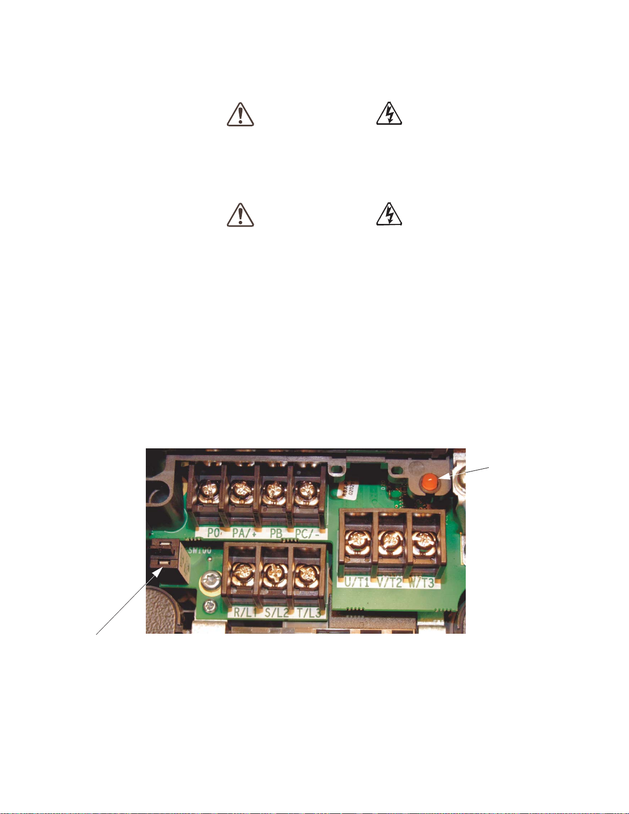
Charge LED
Grounding Capacitor Switch — Pull for Small capacitance/Push for Large capaci tance.
Refer to the section titled Installation Precautions on pg. 4 and the sect io n titled Lead Length
Specifications on pg. 20 before attempting to connect the H9 ASD and the motor to el ectrical power.
Power Connections
Contact with the 3-phase input or output terminals may cause an electrical shock
resulting in injury or loss of life.
See Figure 20 on pg. 26 for a system I/O connectivity sche ma tic.
An inductor (DCL) may be connected a cross the PO and PA/+ termin als to provide additional filtering.
When not used, a jumper must be connected across these terminals (see Figure 20 on pg. 26).
PA/+ and PB are us ed for the DBR connection if using a braking resistor.
PC/- is the negative terminal of the DC bus.
R/L1, S/L2, and T/L3 are the 3-phase input supply terminals for the H9 ASD.
U/T1, V/T2, and W/T3 are the output terminals of the H9 ASD that connect to the motor.
The location of the Charge LED for the smalle r typeform ASD is provided in Figure 2. The Charge
LED is located on the front door of the enclosure of the larger ASDs.
Figure 2. Typical H9 ASD input/output terminals and the Grounding Capacitor Switch.
16 H9 ASD Installation and Operation Manual
Page 25
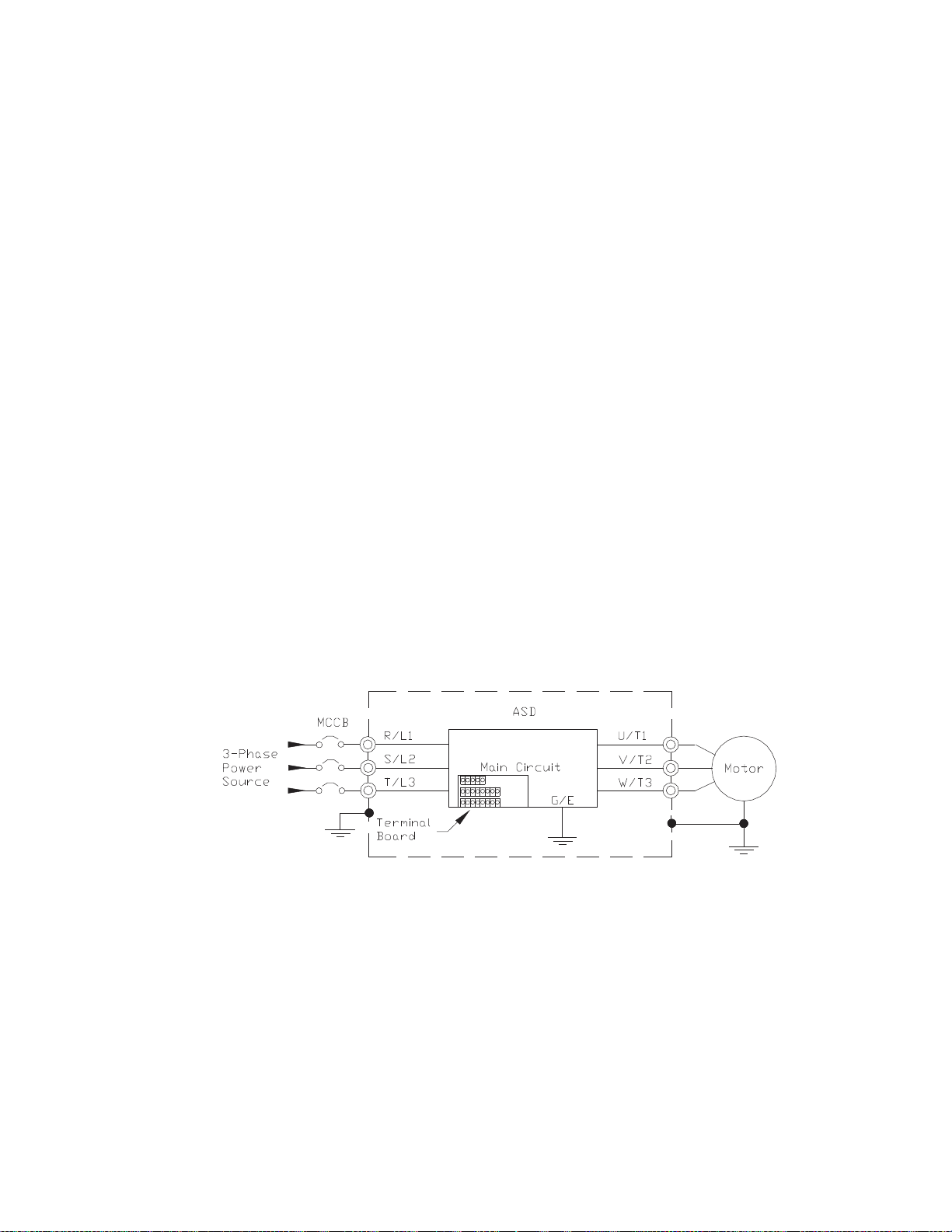
Power Connection Requirements
Connect the 3-phase input power to the input terminals of the H9 ASD at R/L1, S/L2, and T/L3 (see
Figure 3 for the typical el ec tri cal con nec ti on scheme ). Con nect the outpu t of the ASD to the motor f rom
the ASD terminals U/T1, V/T2, and W/T3. The input and output conductors and terminal lugs used
shall b e in accordan ce wi th the requirements li sted in the section tit led Current/Voltage Specifica tions
on pg. 263.
If multiple conductors are used in parallel for the input or output power and it is nec essary to use
separate conduits, each parall el set shall have its own conduit and not sha re its conduit with other
parallel sets — i.e., plac e U1, V1, and W1 in one conduit and U2, V2, and W2 in another (refer to NEC
Article 300.20 and Article 310.4). National and local electrical codes should be refe renced if three or
more power conducto rs are run in the same conduit (re fer to 2005 NEC Article 310 adj us tm ent factors).
Note: National and local codes should be referenced when running more than three
conductors in the same conduit .
Install a molded case circ uit breaker (MCCB) or fuse be tween the 3-phase power source and the H9
ASD in accordance with the faul t curre nt setting of the H9 ASD and 2005 NEC Article 430.
The H9 ASD is designed and tes ted to comply with UL Standard 508C. Modifications to the ASD
system or failure to comply with the short circuit protection requirements outlined in this manual may
disqualify the UL rating. See Table 22 on pg. 267 for typeform-specific shor t circuit protec tion
recommendations.
As a minimum, the installation of the H9 ASD shall conform to 2005 NEC Article 110, the
Occupational Safety and Health Administration requirements, and to any other local and regional
industry code s a nd st andards.
Note: In the event that the motor rotate s in the wrong direction when powered up, reverse
any two of the three H9 ASD output power leads (U, V, or W) connected to the motor.
Figure 3. H9 ASD/Motor typical connection scheme.
H9 ASD Installation and Oper ation Manual 17
Page 26

System Grounding
Proper grounding helps to prevent electrical shock and to reduce electrical noise. The H9 ASD is
designed to be grounded in accordanc e with Article 250 of the 2005 NEC or Section 10/Par t One of
the Canadian Electrical Code (CEC).
The grounding condu ctor shall be sized in accordan ce with Arti cle 250-122 of the NEC or Part One-
Table
6 of the CEC.
The Metal Of Conduit Is Not An Acceptable Ground.
The input, output, and control lines of the system shall be run in separate metal conduits and each shall
have its own ground conductor.
ASDs produce high-fre quency noise — take steps to avoid the negative effects of noi se. L is ted below
are some ex amples of measures that wi l l he l p to co mb at noise prob l ems.
• DO NOT install the input power and output power wires in the same duc t or in parallel with each
other, and do not bind them together .
• DO NOT install the input/output power wires and the wires of the control circuit in the same duct
or in parallel with each other, and do not bind them together.
• Use shielded wires or twis te d wires for the control circuits.
• Ensure that the grounding terminals (G/E) of the H9 ASD are securely connected to groun d.
• Connect a surge suppress or to every electromagnetic contactor and every relay installed near the
ASD.
• Install noise filters as required.
The Grounding Capacitor Switch and the 3-phase input and output terminals are shown on pg. 16 (see
pg. 5 for more information on the Grounding Capacitor Switch).
Grounding Capacitor
The Grounding Capacitor plays a role in minimizing the effects of leakage current through the ASD
system and through ground paths to other sys tems. Leakage current may cause the improper operation
of earth-leakage curre nt breakers, leakage -current relays, ground relays, fire alarms, and othe r sensors
— and it may cause superimposed noise on CRT screens.
The Grounding Capacitor Switch allows the user to qui ckly cha nge the value of the le akage- redu ction
capacitance of the 3-phase input circuit. See figur es 4, 5, 6, and 7 on pg. 19 fo r an electrical depiction of
the leakage-reduction functiona lity and the methods used to change the capac itance value. The method
used is typeform-specific.
If using a 460-volt 5 HP ASD or a 460-volt ASD that is i n the range of 7.5 HP to 25 HP, and the U/T1,
V/T2, and W/T3 connections to the motor are 100 meters or more in length, the ASD Carrier
Frequency must be set to 4 kHz or less when activating or deactiv ating the Grounding Capacitor
Switch. ASD ov erheat ing may o c c ur if the Carrie r Freq uency is set above 4 kHz when activating or
deactivating the Grounding Capacitor Switch.
See pg. 5 for more information on the Grounding Capacitor Switch and pg. 16 for the location.
18 H9 ASD Installation and Operation Manual
Page 27

Figure 4. The Grounding Capacitor Switch is
used on typeforms 230-volt 0.5 HP to 10 HP
and the 25 and 30 HP/460-volt 1.0 HP to
250 HP.
The value may be set to Maximum (default
setting) or to zero by pushing or pulling the
switch actuator, respectively.
Figure 5. The Grounding Capacitor
Switch is used on typeforms 230-volt
15 HP to 20 HP and the 40 HP to 60
HP/460-volt 30 HP to 100 HP.
The value may be set to Large
(default setting) or Small by pushing
or pulling the switch actuator,
respectively.
Figure 6. The Grounding Capacitor Bar is
used on typeforms 230-volt 75 HP and the
100 HP/460-volt 125 HP and the 150 HP.
The value may set to Large or Small (default
setting) by connecting or disconnecting the
switching bar, respectively.
Figure 7. The Ground ing Cap aci tor Screw is
used on typeforms 460-volt 175 HP and
above.
The value may set to Large or Small (default
setting) by placing the screw in the A position
or by placing the screw in the B position,
respectively.
H9 ASD Installation and Oper ation Manual 19
Page 28

Lead Length Specifications
Adhere to the NEC and any local codes during the installation of ASD/Motor systems. Excessive lead
lengths may adversely effect the performance of the motor. Special cables are not re quired. Lead lengths
from the ASD to the motor in excess of those listed in
of the ASD. Table 1 lists the suggested maximum lead lengths for the listed motor voltages.
Table 1.
Table 1 may require filters to be added to the output
Model
230 Volt All 1000 feet
460 Volt
Note: Contact Toshiba for application assistance when using lead lengths in excess of those
listed.
PWM Carrier
Frequency
< 5 kHz 600 feet
≥ 5 kHz 300 feet
NEMA MG-1-1998 Section IV Part 31
Compliant Motors
2
Exceeding the peak voltage rating or the allowable ther mal rise time of the motor
insulation will reduce the life expectancy of the motor.
When operating in the Vector Control mode the carrier frequency should be set to
2.2
kHz or above.
20 H9 ASD Installation and Operation Manual
Page 29

I/O and Control
The H9 ASD can be controlled by several input types and combinati ons thereof, as well as operate within
a wide range of output freque ncy a nd voltage level s. This section discusses the H9 ASD control methods
and supported I/O functions.
The Terminal Board supports d iscrete and analog I/O functions and is shown in F igure 9 on pg. 24. Table
2 lists the names, functions, and the settings (default settings of programmable terminals) of the input and
output terminals of the Terminal Board.
Note: To use the input lines of the Terminal Board to provi d e Run commands the Command
Mode setting must be set to Terminal Block.
Figure 20 on pg. 26 shows the typica l connection diagram for the H9 ASD system.
Table 2. Terminal Board terminal names and functions.
Te rm. Na me Input/Output
ST
RES Reset — Multifunctional programmable discrete input. Resets ASD.
F
R
S1
S2
S3
S4
O1A/B (OUT1)
O2A/B (OUT2)
FLC
FLB
FLA
RR
RX
V/I
(Select V or I
via SW301)
AM
FM
SU+
P24
PP
FP Pulsed Output
IICC
CCA — Return for the RR, RX, P24, and the PP terminals.
CC
Discret e Input
Connect to CC
to activate
(Sink mode) .
Switched
Output
Analog Input
Analog
Output
DC Input Externally-supplied 24 VDC backup control power (1.1 A max.). Referenc e CC.
DC Output
— Return for the V/I input terminal.
— Return for discrete input terminals and the SU+ input terminal.
Standby — Multifu nct io nal pr ogr ammabl e di scre te inpu t. Act iv ation req uired
for normal ASD operation.
Forward — Multifunctional programmable discrete input.
Reverse — Multifunctional programmable discrete input.
Prese t Speed 1 — Multifunctional programmable discrete input.
Prese t Speed 2 — Multifunctional programmable discrete input.
Prese t Speed 3 — Multifunctional programmable discrete input.
Prese t Speed 4 — Multifunctional programmable discrete input.
Low Speed — Multifunctional programmable discret e output.
Reach Frequency — Multifunctional programmabl e discrete output.
Fault relay (common).
Fault relay (N.C.).
Fault relay (N.O.).
Multifunction programmable anal og input (0.0 to 10 volt input — 0 Hz to
Maximum Frequency). Reference CCA.
Multifunctional programmable analog input (-10 to +10 VDC input —
0 to ±Maxim um Frequency). Reference CCA.
V — Multifunctional programmable isol ated analog voltage input
(0 to 10 VDC input — 0 to Maximum Frequency output). Reference IICC.
I — Multifun ctional programmable isolate d analog current input (0 [4] to
20 mADC inpu t — 0 to Max im um Frequency output). Reference IICC.
Current output that is proportion al to the magni tude of the function assigned
to this term i na l (s ee
Current or voltag e output that is proportion al to the magni tude of the function
assigned to this terminal (see
at F681. Reference CC.
24 VDC (200 mA max.) output. Reference CCA. Figure 14 on pg. 25.
10.0 VDC/10 mA voltage source for the externa l potentiometer . CCA Ref. Figure 15 on pg. 25.
Frequency Pulse — Multifunctional programmable out put pulse t rain of a
frequency based on the output frequency of the ASD (see
Function (Default setting if progr am m able)
(see Terminal Description s on pg. 22)
Table 6 on pg. 239). Reference CC.
Table 6 on pg. 239). The output selection is set
Table 6 on pg. 239).
Circuit Config.
Figure 10 on pg. 25.
Figure 16 on pg. 25.
Figure 19 on pg. 25.
Figure 11 on pg. 25.
Figure 12 on pg. 25.
Figure 13 on pg. 25.
Figure 18 on pg. 25
Figure 17 on pg. 25.
Do Not connect to
Earth Gnd or to
each other.
H9 ASD Installation and Oper ation Manual 21
Page 30

Terminal Descriptions
Note: The programmable term inal assignments may be accessed and changed from their
default settings as mapped on
Direct Access ⇒ applicable paramete r number. See th e sec tio n tit le d Program Mode
Menu Navigation on pg. 46 for the applicable Direct Access parameter numbers.
For further information on terminal assignments and default setting changes, see the
sections titled
Note: See the section titled Cable/Terminal/Torque Specifications on pg. 265 for the H9
ASD conductor and terminal electrical spec ifications.
Note: Programmable te rminals will not retain their settings indefinit ely in the event o f a
power loss. Connect an external +24V DC supply to the SU+ terminal to retain the
programmable settings in the event of Control Power loss (see
ST — The default se tting for this terminal is the Standby mode controller. As the default setting, this
terminal must be activate d for normal system oper ation. The ST t ermin al is act ivate d by connec ting CC
to this ter minal (Sink mode). When deactivated the Not Ready to Run icon is displayed on the LCD
screen as sh own in
functi o ns that are listed in Table 5 on pg. 236 (see F113).
RES — The default setting for this terminal is Reset. The RES termin al is activated by connecting CC
to this termina l (S ink mode). A momentary connection to CC resets the ASD and any fault indications
from the display. Reset is effective when faulted only. This input termin al may be program me d to any
one of the functions that are listed in
Default Setting Changes on pg. 74 and Ter minal on pg. 47.
Figure 22. on pg. 31.This input terminal may be programmed to any one of the
pg. 46 or via the Direct Access method: Program ⇒
Figure 20 on pg. 26).
Table 5 on pg. 236 (see F114).
F — The default setting for this terminal is the Forward Run Command. The F term in a l is ac ti v a t ed
by connecting CC to this terminal (Sink mode). This input terminal may be programmed to any one of
the functions that are listed in
R — The default setting for this terminal is the Re verse Run Command. The R termina l is activat ed
by connecting CC to this terminal (Sink mode). This input terminal may be programmed to any one of
the functions that are listed in
S1 — The default setting for this terminal is the Preset Speed #1 Command. The S1 terminal is
activated by connecting CC to this terminal (Sink mode) . This input termina l ma y be progr ammed to
any one of the functions that are listed in
S2 — The default setting for this terminal is the Preset Speed #2 Command. The S2 terminal is
activated by connecting CC to this terminal (Sink mode) . This input termina l ma y be progr ammed to
any one of the functions that are listed in
S3 — The default setting for this terminal is the Preset Speed #3 Command. The S3 terminal is
activated by connecting CC to this terminal (Sink mode) . This input termina l ma y be progr ammed to
any one of the functions that are listed in
S4 — The default setting for this terminal is the Preset Speed #4 Command. The S4 terminal is
activated by connecting CC to this terminal (Sink mode) . This input termina l ma y be progr ammed to
any one of the functions that are listed in
RR — The default function assigned to this terminal is the Frequency Mode 1 setting. The RR
terminal accepts a 0 – 10 VDC input signal that is used to carry out the function assigned to this
terminal. This input terminal may be programmed to control the speed or torque of the motor via an
amplitude se tting or regulate by setting a limit. The gain an d bias of this terminal may be a djusted for
application-specific suit ability (see
the RR terminal. This terminal reference s CC A.
Table 5 on pg. 236 (see F111).
Table 5 on pg. 236 (see F112).
Table 5 on pg. 236 (see F115).
Table 5 on pg. 236 (see F116).
Table 5 on pg. 236 (see F117).
Table 5 on pg. 236 (see F118).
F210 – F215). See Figure 20 on pg. 26 for an electrical depiction of
22 H9 ASD Installation and Operation Manual
Page 31

RX — The default fu nction assigne d t o this termi nal is the Torque Comma nd se tti ng. The RX te rmina l
accepts a ±10 VDC input signal that is used to carry out the function assigned to this terminal. This
input terminal may be programmed to raise or lower the speed or torque of the motor via an amplitu de
setting or thi s te rminal may be used to regulat e the speed or torque of a motor by sett ing a limit. The
gain and bias of t his te rm inal m ay be adj us ted f or a pplic at ion- spec ifi c sui tab ili ty (s ee
F216 – F221). See
Figure 20 on pg. 26 for an electrical depiction of the RX te rminal. This terminal references CCA.
V/I (I) — The function of the I input is to receive a 0 – 20 mA input signal that controls a 0 – 80 Hz
output. T his is an isolated input te r minal. This terminal is identified as V/I on the terminal board and
may be programmed to control the speed or torque of the motor. This terminal cannot be used when
using the V input function. SW301 must be set to I to receive a current input signal at this terminal and
is the def ault setting from the factory (see
Figure 9 on pg. 24). This terminal refere nces IICC. Scaling
of the V/I terminal is accomplished via F201 – F206. The gain and bias of t his te rmina l may b e adjus ted
for appli cation- sp ec if i c su it ab i li ty ( s ee F470 and F471).
V/I (V) — The function of the V input termin al is to receive a 0 – 10 VDC input signal that controls a
0 – 80 Hz output. This is an isolated input terminal. This term inal is identified as V/I on the terminal
board and may be programm ed to cont rol the s peed or tor que of the motor. This terminal cannot be used
when using the I input. SW301 must be set to V to receive a voltage input signal at this te rminal (see
Figure 9 on pg. 24). This terminal references IICC. Scaling of the V/I terminal is accomplis h ed vi a
F201 – F206. The gain and bias o f t h is terminal may be adju sted for application-specific suitability
(F470 and F471).
SU+ — Externally suppli ed +24 VDC ± 10% @ 1.1 A (minimum) backup contro l power. This terminal
references CC.
P24 — +24 VDC @ 200 mA power supply for cu stomer use. This term inal references CCA.
PP — The function of out put PP is to provide a 10 VDC/10 m ADC output that may be divided using a
potentiome ter. The tapped voltag e is applied to the RR input to provide manual control of the RR
programmed function. This terminal refe rences CCA.
O1A/B (OUT1A/B) — The default function assigned to this term inal is Output Low Speed. This
output may be programmed to provide an indication (open or closed) that any 1 of the functions that are
listed in
Table 8 on pg. 241 has taken plac e. This function may be used to signal external e quipm ent or
to activ a t e th e b r ak e ( see F130). The OUT1 terminal is rated at 2 A/120 VAC and 2 A/30 VDC.
O2A/B (OUT2A/B) — The default function assigned to this terminal is ACC/DEC Complete. This
output may be programmed to provide an indication (open or closed) that any 1 of the functions that are
listed in
Table 8 on pg. 241 has taken plac e. This function may be used to signal external e quipm ent or
to activ a t e th e b r ak e ( see F131). The OUT2 terminal is rated at 2A/120 VAC and 2A/30 VDC.
FP — The default function of this output terminal is to output a series of pulses at a rate that is a
function of the output frequency of the ASD. As the output frequency of the ASD goes up so does the
FP output pulse rate. This terminal may be programmed to provide an output pulse rate that is
proportional t o an y one of th e it ems li sted i n
T abl e 6 on pg. 239. For further informatio n on this terminal
see F676 on pg. 196.
AM — This output terminal produces an output curre nt that is proportional to the magnitude of the
function assigned to this terminal. The available assignme nts for this output t erm inal are lis ted in
Table
6 on pg. 239. For further information on this terminal see F670 on pg. 194.
FM — This output terminal produces an output current or voltage that is proportional to the magnitude
of the function assi gned to this terminal. The available assignments for this output terminal ar e listed in
Table 6 on pg. 239. For further information on this terminal see F005 on pg. 78. The Voltage/Current
output sele ction is performed at F681.
H9 ASD Installation and Oper ation Manual 23
Page 32

FLC — FLC is the common leg of a single-pole double-throw form C relay. The FL relay is the Fault
Note: The relay is shown in the Faulted or de-energ ized condition.
During normal system ope ration the relay connection is FLC-
to-FLA.
J101
TB1
TB2
TB3
J100
SW200
TB4
SW301
RES
CC
F
R
S1
S2
S3
S4
CC
ST
FP
+SU
Ensure that the ground screw is securely in place to
prevent arcing, intermittent operation, or system
failure.
1 to 2 = Sink
2 to 3 = Source
1 to 2 = System Supplied
2 to 3 = Ext. Supplied
(24V )
V/I Switch
See F igure 20 on pg. 26 for more information on the Terminal Board connections .
Half/Full Duplex Switch
CAUTION
S4
RS485 4-Wire Communication
Relay by defa ult, but may be programmed t o any one of the conditions lis ted in Table 8 on pg. 241. For
further information on this terminal see F132 and Figure 8.
FLB — The normally-closed leg of the FL relay.
FLA — The normally-open leg of the FL relay.
Note: The FLA, FLB, and FLC contacts are rated at 2A/120 VAC and 2A/30 V DC.
Figure 8. FLA, FLB, and FLC switching contacts shown in the de-energized state.
Figure 9. Terminal Board. Sink Source
24 H9 ASD Installation and Operation Manual
See the section titled Te rm inal Descriptions on pg. 22 for terminal descriptions.
See the section titled Cable/Terminal/T orque Specifications on pg. 265 for information on the proper
cable/terminal sizes and torq ue specifications when maki ng Terminal Board co nnections.
Page 33

I/O Circuit Configurations
Figure 10. Discrete Input. Figure 11. RR Input.
Figure 12. RX Input. Figure 13. V/I Isolated Input.
Figure 14. P24 Output. Figure 15. PP Output.
Figure 16. OUT1/OUT2 Output. Figure 17. FP Output.
Figure 18. AM/FM Outp u t. Figure 19. Fault Relay (shown faulted).
H9 ASD Installation and Oper ation Manual 25
Page 34

Typical Connection Diagram
Note: When connecting multiple wires to the PA, PB, PC, or PO
terminals, do not connec t a sol id w ire an d a strande d wi re to the
same terminal.
Figure 20. The H9 ASD typical connection diagram.
Note: The AM, FM, and the +SU analog terminals are referenced to CC.
Note: The RR, RX, P24, and the PP analog terminals are referenced to CCA.
Note: The isolate d V/I analog terminal references IICC.
26 H9 ASD Installation and Operation Manual
Page 35

Startup and Test
Before turning on the ASD ensure that:
• R/L1, S/L2, and T/L3 are connected to the 3-phase input power.
• U/T1, V/T2, and W/T3 are connected to the motor.
• The 3-phase input voltage is within the specified tolerance.
• There are no shorts and all grounds are secured.
• All per sonnel are at a safe distance from the motor and the mo to r-driven equipment.
H9 ASD Installation and Oper ation Manual 27
Page 36

Electronic Ope rat or In terf ace
The H9 ASD Electronic Op er ator Interface (EOI) is comprised of an LED display , an LCD display, two
LEDs, a rotary encoder, and five keys. These items ar e describ ed below a nd th eir loc ations ar e prov ided in
Figure 21. on pg. 29.
EOI Operation
The EOI is the primary input/output device for the user. The EOI may be used to monitor system
functions, in put data into the system, perform diagnostics, and view performance data (e.g. , motor
frequency, bus voltage, torque, etc.).
The software used with the H9 ASD is menu drive n; thus, making it a select and cl ick environmen t. The
operating parameters of a motor may be selected and viewed or changed using the EOI (or via
communications).
EOI Remote Mounting
The EOI may be mounted remotely using the optional ASD-MTG-KIT9. The kit contains a ll of the
hardware required to mount the EOI of the 9-Series ASD remotely.
System operation and EOI oper ation while using the remotel y-mounted EOI are the same as with the
ASD-mounted configuration.
28 H9 ASD Installation and Operation Manual
Page 37

EOI Features
LCD Display
Rotary Encoder
Local/Remote
Mode
Key
Press for Enter Key
Escape Key
Stop|Reset Key
Key (LED)
Run Key
(LED)
LED Display
LED / LCD Display
}
01:14
Selected
Number
item:
(01)
of items:
(14)
Program
Terminal...
Direct Access...
Utilities...
Protection...
Fundamental...
Figure 21. The H9 ASD Electronic Operator Interface features.
LED Display — Displays the running frequency, and active Fault and/or active Alarm information.
Rotary Encoder — Used to access the H9 ASD menu selections, change the value of a displaye d
parameter, and performs the Enter key function. Turn the Rotary Encoder either clockwise or
counterclockwise to perform the Up or Down func tions of the displ ayed menu sel ecti on. Press the Rotar y
Encoder to perform the Enter (select) function.
LCD Display — Displays configuration information, performance data (e.g., outp ut frequency, bus
voltage, torque, etc.), diagnostic information, and LED Display information in expanded norm al text.
Local|Remote Key — Toggles the system to and from the Local and Remote modes. The
Local|Remote Key is disabled while the Fault screen is displayed. The LED is on when the system is in
the Local Command mode. The Local mode allows th e Command and Frequency control functions to
be carried out via the EOI.
The Remote mode enables the Command and Frequency control fun ctions to be carried out via the
Terminal Board, RS485, Communication Board, or Pulse Input. The selection may be made via
Program ⇒ Fundamental ⇒ Standard Mode Select ion ⇒ Command Mode and Frequency Mode 1,
respectively.
The availability of Local mode control (Command and Frequency control) may be disabled via Pro gram
Utilities ⇒ Prohibition ⇒ Local/Remote Key Command Override and Local/Remote Key
⇒
Frequency Override. The availability of the Local mode of operation may be reinstated by changing thi s
setting or performing a Reset (see F007).
ESC Key — The Escape key returns the system to the previous level of the menu tree, toggles between
the EOI Command screen and the Frequency Command screen, or cancels changes made to a field if
pressed while still in the revers e video mode (dark background/light text). The 3 functions are menuspecific.
Run Key — Issues the Run command while in the Local mode. The Run key LED Illuminates green
while stopped or red while running to alert personnel.
Mode Key — Pro vi d es a means to access the three roo t men u s. P r essing the Mode Key key repeatedly
loops the system through the three root menus (se e
menus, the Program menu will display the root menu screen or the Program sub-menu item being
accessed prior to pressing the Mode key.
H9 ASD Installation and Oper ation Manual 29
Fig u r e 27 on pg. 41). While looping through the root
Page 38

Stop|Reset Key — This key has three functions.
LED/LCD Display Information
LED
LCD
LED
LCD
A A 1 1
b b 2 2
C C 3 3
d d 4 4
E E 5 5
F F 6 6
G G 7 7
H H 8 8
I I 9 9
J J 0 0
L L
M M
n n
O O
P P
b
q
r r
S S
t t
U U
v v
y y
- -
1. Issues the Off command (d e celerates to Stop at the programmed rate) if pressed once while in the
Local mode.
2. I nitiates an Emer gency Of f Fault if pressed twice quickly from the Local or Remote modes. The
Emergency Off fun ction terminates the H9 ASD output and applies the brake if so configured.
3. Resets active Faults and/or activ e Alar ms if pressed twice quickly. The source of the Fault or
Alarm must be determined and corrected before normal ASD operation can resume.
Run Key Status LED — Illuminates green while stopped or red while runni ng.
LED Display
The LED display is used to display the output frequency, active alarms and/or active faults.
If there are no active alarms or fault s, the output frequency is displayed.
During an active alarm, the display to ggles to and from the running frequency and the active alarm.
During an active fault, the fault is disp layed.
LED Character/Font Information
Characters dis playe d on the L ED displa y wil l be of
the seven-segmen t format. Not all alpha-numeric
characters are available or used with the LED
display.
Listed are the seven-segment characters used at the
30 H9 ASD Installation and Operation Manual
LED display along with the sam e ch aracters as
they are displayed on the
LCD Display.
Page 39

LCD Display
Speed Reference %
Speed Reference Hz
User-selected
Monito red Parameters (see
Not-Ready-to-Run
Indicat o r (ST-to -C C required)
Ready-to-Run Indicator
appears whe n ST is connect ed
to CC
Shows d iscrete I/O terminal status when n ot in alarm mode.
Main Monitor Sel ections on pg. 45)
Figure 22. Frequency Command Screen Items.
Forward Run Active
Reverse Run Active
Discrete I/O terminal status or
alarm condi tion
Item Number 1 of 43
Speed at Trip (if applicable)
Active Frequency
Active DC Bus Voltage
Monitored items
Command Active output Current
ASD Output Voltage
Screen Name
(only 5 items listed)
Active Frequency
Prim ary Menu Items
Screen Name
Item Number 1 of 15
Prog ram Menu it e m s
{
(only 5 items listed)
Program
Fundamental...
Terminal...
Direct Access...
Utilities...
Startup Wizard...
01:15
The LCD Display is the primary us er input/output information center. Parameter settings may be vie w ed
or changed using the LCD displ ay module of the EOI. To view or change a parameter setting using the
LCD display, press the Mode key until the Program menu is displayed. Turn the Rotary Encoder until
the desired Primary Menu item is within the cursor block. Pr ess the Rota ry Encoder to select the item
from the Primary Men u (repeat the press-to-select for submenu items).
See the se ct io n titled Default Setting Changes on pg. 74 for more information on changing parameter
settings.
Upon reaching the desired parameter selection the current setting may be viewed, or it may be changed by
pressing the Rotar y Encoder and the setting wil l ta ke on the reverse vide o format (dark back ground /light
text). Turn the Rotary Encoder to change the parameter setting. Press the ESC key while the new
parameter setting is in the reverse video mode to exit the selection without saving the change or press the
Rotary Encoder while the parameter setting is in the reverse video mode to accept the new setting.
Repeated ESC key entries at any time takes the menu back one level each time the ESC key is pressed
until the Frequency Command screen i s reached. Further ESC entries will toggle the syste m to and from
the Frequency Command scre en and the EOI Comm and menu.
Note: Changes carried out from the EOI Command screen will be effective for EOI-
controlled ASD oper ation on ly. Se e the se ctio n tit le d
further infor m ation on EOI Command Mode operations.
Primary Menus of the LCD Display
The thr ee Pr i mary screen s of th e LCD displ ay ar e d isp l ay ed while ac ce s si n g th e as so ci at ed op e r at in g
mode : the Frequency Command, Monitor, and the P rogram Menu screens.
EOI Command Mode on pg. 42 for
Figure 23. Monitor Screen Items (see pg. 43 for more on the Monitor Screen items).
Figure 24. Program Menu Items (see pg. 46 for more on the Program Menu Screen).
H9 ASD Installation and Oper ation Manual 31
Page 40

LED/LCD Display Installation Note
When installin g the LED/LCD display module of the EOI ensure that the left side of the display is
inserted first with the top and bottom catches (see Phillips screws at unders ide of display) securely in
place. This ensures the proper alignment an d ele ctrical connection of the CNX connector of the LED/
LCD display module PCB . Th en gently hold the display in place while securing the Phillips mounting
screw.
If improperly seated, the pe riphery of the LED/LCD display module will not be flush with the front panel
surface and the unit will not function prop erly .
32 H9 ASD Installation and Operation Manual
Page 41

Keypad Remote Mounting
The H9 ASD may be controlled from a remotely-mounted keypad. For safe ty and applicati on-specific
reasons, some ASD instal lations will warrant that the operator not be in the vicinity during operat ion or
that the keypad not be att ached to the ASD housing. The keypad may be mounted either with or without
the optional Remote Mounting Kit (P/N ASD-MTG-KIT). The ease of installation is enhanced by the
Remote Mounting Kit (P/N 58333) which allows for keypad placement and easier cable routing.
Remote mounting will also allow for multipl e keypad mountings at one location if controlling and
monitoring several AS Ds from a central location is required.
The keypad can operate up to 9 feet away from the ASD. A keypad extender cable is required for remote
mounting. The keypad extender cable is available in a 9-ft. length and may be ordered through your sales
representative.
The optional dust cov er (P/N AS D-BP C) may be us ed to cover the front panel opening of the ASD
housing after removi ng the keypad.
Remote Keypad Required Hardware
Keypad Mounting Hardware
• EOI Remote-mount Housing — P/N 58333 (included with 230-volt 40-HP and above; and with the
460-volt 75 HP and above)
• 6-32 x 5/16” Pan Head Screw — P/N 50595 (4 ea.)
• #6 Split-Lock Wa sher — P/N 01884 (4 ea.)
• #6 Flat Washer — P/N 01885 (4 ea.)
Bezel Plate Mounting Hardware
• Bezel Plate — P/N 52291
• 10-32 Hex Nut — P/N 01922 (4 ea.)
• #10 Split-Lock Wa s her — P/N 01923 (4 ea.)
• #10 Flat Washer — P/N 01924 (4 ea.)
• Dust Cover — P/N ASD-BPC (Optional)
Extender Cable
• ASD-CAB10F: Cable, 9 ft.
Keypad Installation Precautions
Install the unit secu rely in a well ven til ated a rea tha t is o ut of direc t sunl igh t using the four m ount ing holes
of the rear of the keypad. The ambie nt temperature rating for the keypad is 14° to 104° F (-10° to 40° C).
• Select a mounting location that is easily accessible by the user.
• Avoid installation in areas where vibration, hea t, humidity, dust, metal particles, or high levels of
electrical noise (EMI) are present.
• Do not instal l the keypad where it may be exposed to flammable chemic als or gas es, water, solvents,
or other fluids.
• Turn on the power only after securing the front cover to the ASD.
H9 ASD Installation and Oper ation Manual 33
Page 42

Keypad Remote Mounting w/o the ASD-MTG-KIT
Note: See Figure 25 for the dimensions and the item locat ions refe renced in steps 1 through 5.
1. At the keypad mounting location, mark the 3.80” by 3.56” hole and the four 7/32” screw holes.
2. Cut the 3.80” by 3.56” rectangular hole.
3. Dri ll the four 7/32” screw holes.
4. At tach a nd secure the EOI t o the front side of the mo unting l ocati on using the four 6- 32 x 5/16” p an
head screws, the #6 sp lit lock washers, and the #6 flat washers.
5. Connect the extension cable.
Keypa d Dim e ns ions (mounting)
Figure 25. Keypad Mounting Dimensions.
34 H9 ASD Installation and Operation Manual
Page 43

Keypad Remote Mounting using the ASD-MTG-KIT
Note: See Figure 26 for the dimensions and the item locations referenc ed in steps 1 through 6.
1. At the keypad mounting location, mark the 4.60” by 4.50” hole and the four 11/32” screw holes.
2. Cut the 4.60” by 4.50” rectangular hole.
3. Dri ll the four 1 1/32” holes for the Bezel Plate mount.
4. At tach and secure the Bezel plate to the fr ont s ide of the mounting l ocation using the four 10-32
hex nuts, #10 split lock washers, and the #10 flat washers.
5. At tach and secure the keypa d to the front side of the Bezel plate using the four 6-32 x 5/16” pan
head screws, #6 split lock washers, and the #6 flat washers.
6. Connect the extension cable.
Keypa d ASD- MTG-KIT Dimensions (mounting)
Figure 26. Keypad Bezel Plate Mounting Dimensions.
H9 ASD Installation and Oper ation Manual 35
Page 44

Command Mode and Frequency Mode
Control
Command control includes instructions such as Stop, Run, Jog, etc. The source of the Command
signal must be estab lished for normal operation.
Frequency commands control the output speed of the H9 ASD. The source of the frequency (spee d)
control signal m ust be established for normal operation.
The source of the command control and speed control may be either internal or ext ernal. Once the
source signal is selected for either funct ion, the system may be configured to use the selected sign al a ll
of the time or switc h under user-defined conditions.
Command and Frequency control may be carried out using any one of several control m ethods (signal
sources) or combinations thereo f . In the event that multiple control commands are received, the signal
sources are assig ned priorit y le vels. Th e primary cont rol method for Command and Frequency control
uses the settings of
Command Con tro l (F003 )
The Command Mode selection of F003 establishes
the primary sourc e of the command input for the ASD.
However, the Override feature may supersede the
F003 setting as indicated in Table 3.
Table 3 on pg. 38 shows the hierarchy of the control
sources managed by the O verride function. The level
of the control ite m on the hierarchy is list ed from left
to right, most to least, respectively. As indicated in the
table , th e Override setting may supersede the
F003 and F004, respectively.
F003 setting.
Placing the EOI in the Local mode selects the RS485 (2-wire) as the Command Mode co ntrol source.
Local mode operation m ay be superseded by other Override settings.
Example: With the EOI se t to Local, Communication Board input or RS485 (4-wire) input will
supersede EOI control input.
The remaining con trol sources may be plac ed into the overr ide mode using communic ations.
The source of the Command control signal may be selected by:
•The F003 setting,
• Pla cing an item from the list below in th e Override mode via communications, or
• Placi ng the EOI in th e Local mode (places only the RS485 [2-wire] or the RS485 [4-wire] in the
Override mode).
Possible Command signal source selections include the following:
• Terminal Block (default),
• EOI Keypad,
• RS485,
• Communic ation Option Boar d, or
• F003 setting (is used if no sig nal sources are in the Override mode).
Note: The Terminal Board is placed in th e Override mode by assigning a discrete terminal
to Command Terminal Board Priority and connecting the terminal to CC. Once
activated (Run command requir ed), the Terminal Board settings will be used for
Override Command control (F, R, Preset Speeds, etc.).
36 H9 ASD Installation and Operation Manual
Page 45

Frequency Control (F004)
The Freq uency Mo de 1 (or the Frequency Mode 2)
setting esta blishes the user-selected source of the
frequency-control input for the H9 ASD. The signal
source selected here is used for speed control unless
the R e f erence Priorit y Se le ct i o n parameter is
configured to switch this setting automatically (see
F200) or if the Override feature is en a bl ed .
Table 3 on pg. 38 shows the hierarchy of the control
sources managed by the Override function. The level of the control item on the hierarchy is listed from
left to right, most to least, respect ively. As indicated in the table, the Override setting may supersede
the selection at
Placing the EOI in the Local mode selects the RS485 (2-wire) as the Frequency Mode 1 control
source. Local mode operation may be superseded by other Override settings.
Example: With the EOI se t to Local, the Communication Board input or the RS485 (4-wire) input
will supersede EOI cont rol input.
The remaining con trol sources may be plac ed into the overr ide mode using communic ations.
The source of the Frequency control signal may be selecte d by:
•The F004 setting,
• Pla cing an item from the list below in th e Override mode via communications, or
F004.
• Placi ng the EOI in th e Local mode (places only the RS485 [2-wire] in the Override mode).
Possible Frequency control source selections include the following:
• Communic ation Board,
• RS485,
• EOI Keypad,
• Terminal Block (the default se tting), or
• F004 setting (used if no other items a re in the Override mode).
Note: The Terminal Board is placed in th e Override mode by assigning a discrete terminal
to V/I Terminal Priority and connecting th e terminal to CC. Once the discrete
terminal is activated, V/I is used as the Terminal Board Ove rride control item.
Command and Freq ue nc y Control Selections
The user may select only one Command source an d only one source for Frequency control. The
default settings for Command and Frequency control are Terminal Block and RR, respectiv ely.
The H9 ASD has a comman d reg ist er f or each item list ed as a Command or Frequency source . T he
registers store the Override setting for each control source. The registers are continuously scanned to
determine if any of the list ed items are in the Override mode.
For each scan cycle, the command reg isters of the control sources are scanned for the Override setting
in the order that they are listed in
the F requency section detect ed as being in the Overrid e mode will be used for Command and
Frequency control , re spec tiv el y. If no items are dete ct ed as bei ng in the Override mode, the settings of
F003 and F004 will be use d for Command and Frequency control, respectiv ely.
Table 3. The first item of the Command section and the first item of
H9 ASD Installation and Oper ation Manual 37
Page 46

Any or all of the Command and Frequency control input sources may be placed in the Override
mode.
Placing the H9 ASD in the Local mode (Local/ Remote LED on) via the EOI places the RS485 (2-wi re)
control selection in the Override mode for Command and Frequency input (see the section titled
Override Operation on pg. 38 for the proper setting). The Local/Remote control Override feature for
Command and Frequency (or either) may be enabled/disabled at Progra m ⇒ Utilities ⇒ Prohibition
⇒ Local/Remo t e Ke y (Command or Frequency) Override.
Communications may be used to place the rema ini ng Command and eligible Frequency control input
sources in the Override mode. Once placed in the Override mode this setting is valid until it is
cancelled, the power supply is turned off, or the H9 ASD is reset.
Override Operation
The signal sources of Table 3 are scanned fr o m left to righ t in the order that they are lis t ed to determine
which input source s are in the Overrid e mode (active Command or Frequency command pres ent). The
first item det ecte d as havin g the Override function turned on i s the s ele ction t hat is use d for Command or
Frequency control input.
The Override control setting supersedes the setting of the Command mode setting (F003) and the
Frequency mode setting (F004). However, the F003 and F004 setti n g s will be u sed in the event that th e
register scan returns th e condition that none of the liste d items have the Override f ea tu r e tu r n ed on or a
discrete input terminal is set to Serial/Local Switch and is activated.
Command and Freq ue nc y-Control Override Hierarchy
Tabl e 3 lists the input conditions and the resulting output control source selections for Command and
Frequency control Override operation.
The H9 ASD software rea ds the memory locations of the li sted control sour ces from the left to the right.
The firs t item to be r ead that h as th e Override feature turned on will be used for Command or Frequency
control.
Tab le 3. Command and Frequency control hierarchy.
1 2 3 4 5 6 Priority Level
Forced F003/
F004 by I/P
Terminal
(assign to Serial/
Local Switch)
1 X X X X X F003/F004 Setting
0 1 X X X X Communicati on Board
0 0 1 X X X RS48 5 (4-w ire)
0 0 0 1 X X RS 4 8 5 (2 -w i re)
0 0 0 0 1 X Terminal Board
0 0 0 0 0
Note: 1 = Override featur e is turned on for that control input sour ce ; 0 = Override Off; X = Don’t Car e.
Comm.
Board
RS485
(4-wire)
RS485
(2-wire)
Terminal Board
(Binary/BCD Input)
F003/F004
F003/F004
Setting
Command/
Frequency Mode
F003/F004 Setting
38 H9 ASD Installation and Operation Manual
Page 47

Command Control Selections
(Default)
(Default)
The following is a listing with descriptions of the
Command Mode (
Fundamental ⇒ Standard Mode Selection ⇒ Command
Mode Selection)
Settings:
0 — Terminal Block
Allows for Command control input via the
Terminal Board.
2 — EOI Keypad
This sett ing is used for EOI command control.
3 — RS485 (4-wire)
Use this setting if using a remote ly-moun te d EOI for command c ontrol. Connect the EOI to the
RJ45 connector of the Terminal Board.
4 — Communication Option Board
Use this setting if using the optional Communica tion Board for command control.
F003) selections (Program ⇒
.
Frequency Control Selections
The following is a listing with descriptions of the
Frequency Mode (
Fundamental ⇒ Standard Mode Sele ction ⇒
Frequency Mode 1).
Settings:
1 — V/I
This selection is used when a 0 to 10-volt DC
analog input or a 0 – 20 mA DC current input
is used as th e s peed control input. Only one input signal type may be used at a time. Set SW301
to the desired si gnal type.
2 — RR
This selection is used for a 0 to 10-volt DC analog input signal.
3 — RX
This selection is used for a -10 to +10-volt DC analog input signal.
5 — EOI Keypad
This setting is used for EOI frequency control.
6 — RS485 (4-wire)
Use this setting if using a remotely-mounte d EOI f or f r equency control. Connect the EOI to the
RJ45 connector of the Terminal Board.
7 — Communication Option Board
Use this setting if using the optional Communica tion Board for frequency control.
F004) selections (Program ⇒
8 — RX2 Option (AI1)
This selection is used for a -10 to +10-volt DC analog input signal.
H9 ASD Installation and Oper ation Manual 39
Page 48

9 — Option V/I
This setting allows for the use of the optional voltage/current frequency-control interface.
10 — UP/DOWN Frequency
A discrete terminal may be configured to inc r ease or decrease the speed of the motor by
momentarily connecting the assigned terminal to CC. See
F264 on pg. 128 for further
information on this feature.
11 — Pulse Input Option
This setting is used to allow the system to use a pulsed input for frequency control. See PG
Input Point 1 Setting on pg. 122 for further information on this feature.
12 — Pulse Input (motor CPU)
This setting is used to allow the system to use a pulsed input for frequency control. See PG
Input Point 1 Setting on pg. 122 for further information on this feature.
13 — Binary/BCD Input Option
Allows for discrete terminal to be used for frequency-control input.
40 H9 ASD Installation and Operation Manual
Page 49

System Configuration and Menu Options
Root Menus
The Mode key ac cesses the three primary modes of the H9 ASD: the Frequency Command mode, the
Monitor mode, and the Program m od e . F r om eit h er m o de , p re ss th e Mode key to loop through to the
other two modes (see
toggles the menu to and from the EOI Command mode and the Frequency Command mode.
The Alarm or Fault information will be displayed in the event of an active Alarm or Fault. Alarm text
will be displayed on the Frequency Command screen and on the L ED screen when active. Fault
information will be displayed via the Fault screen. See
on Alarms and Trips.
Note: EOI Command mode changes made when accessed via the me thod shown in Figure 27
are effe ctive for EOI control Only.
Figure 27. H9 ASD Root Menu Navigation.
Figure 27). While in the Frequency Co mmand mode, pressing the ESC key
Alarms and Trips on pg. 246 for more informatio n
Frequency Command Mode
Freque ncy Setting
While operating in the Local mode (Local LED is illuminated on the front panel), the runni ng f requency
of the motor may be set from the Frequency Command screen. Using the Ro ta ry Encoder, enter the
Frequency Command value, connect ST to CC, and provide a Run command (F and/or R) and then
press the Run key. The motor will run at the Freq uen cy Comman d speed and may be changed while
running. See
Command m ode.
H9 ASD Installation and Oper ation Manual 41
Figure 22. on pg. 31 a nd Operat ion (Local) on p g. 73 for more in formation o n the Frequency
Page 50

EOI Command Mode
The EOI Co mmand mode is accessed by pressing the ESC key from the Frequency Command screen.
The co n tr o l s ettings of th e EOI Command menu are effe ct iv e fo r EOI control only.
The EOI Co mmand mode provides quick access to the following menu parameters:
Direction — Forward or Reverse.
Stop Pattern — Th e Decel Stop or Coast Stop settings determines the method used to stop the
motor when using the Stop|Reset key of the EOI. The Decel Stop setting enables the Dynamic
Braking system setup at
The Coast Stop settin g allows the motor to s to p at the ra te allowed by th e in ertia of th e load.
Note: The Stop Pattern setting has no effect on the Emergency Off settings of F603.
V/f Group — 1 of 4 V/f profiles may be selected and run. Each V/f profile is comprised of 4 user
settings: Base Frequency, Bas e F requency Voltage, Manual Torque Boost, and Electronic
Thermal Protec tion. Expanded descriptions of these parameters may be found in the section titled
Direct Access Parameter Information on pg. 76.
Accel/Decel Group — 1 of 4 Accel/Decel profiles may be selected and run. Each of the Accel/
Decel profiles is comprised of 3 user settings: Acceleration, Deceleration, and Pattern. Expanded
descriptions of these parameters may be found in the section titled
Information on pg. 76 (or see F009).
F304 or the DC Injection Braking system setup at F250, F251, and F252.
Direct Access Parameter
Feedback in Panel Mode — This feature enables or disables the PID feedback function.
Torque Limit Group — This parameter is used to sele ct 1 of 4 preset posit ive torque li mits to ap ply
to the acti ve motor (of a multiple motor configuration). The settings of profiles 1 – 4 may be setup at
F441, F444, F446, and F448, respectively.
42 H9 ASD Installation and Operation Manual
Page 51

Monitor Mode
The Monitor mode allows the user to monitor motor perform ance variables, control settings, and
configuration da ta during motor operati on. There are 43 ite ms that may be monit ored from this mode. The
items are listed and described below.
Note: The Monitor mode is a read-only mode. The set tings cannot be cha nged from the
Monitor mode. For information on how to change the values, see the section titled
Default Setting Changes on pg. 74.
Note: Any two of the Underlined monitored items may be selected for display at the
Frequency Command screen while running via Program
Monitor Selecti ons.
Note: The F701 sett ing will deter mine if the Curre nt and Voltage values displayed appear
as A (Amps) or V (Voltage ), or if the v alu e is shown as a % (perce ntag e) of the ASD
rating.
Frequency at T r ip — Display the at-trip frequency.
Frequency Reference — Displays the Frequency Setpoint (also called the Commanded
Frequency).
Output Current — Displays the Output Current as a percentage of the rated capacity of the H9
ASD.
DC Bus Voltage — Displays the Bus Voltage as a percentage of the rated capacity of the H9 ASD.
Outp ut Voltage — Displays the Output Voltage as a percentage of the r at e d cap a ci ty of th e H9
ASD.
AM Output — Displays the AM output terminal value for the func tion assigned to the AM terminal.
FM Output — Displays the FM output terminal value for the function assigned to the FM terminal.
Motor OL (Overload) Real — Displays the real-time Motor Overload value as a percentage of
the rated c apacity of the motor.
Motor OL (Overload) Trip — Displays the Motor Overload Trip value as a per centage of th e
rated capacity of the mot or.
Motor Loa d — Displays the re al-time Motor Load as a percenta ge of the r ate d capacity of the
motor.
ASD OL (Overload) Real — Displays the real-time ASD Overload as a percentage of the rated
capacity of the H9 ASD.
ASD OL (Overload) Trip — Displays the ASD Overload Trip value as a percentage of the rated
capacity of the ASD.
ASD Load — Displays the ASD Load as a percentage of th e rat e d ca p acity of the H9 A SD .
Run Time — Dis plays th e Cumulative Run Time in hours.
Compensation Frequency — Disp lays the Output Frequency after the application of the slip
compensation correction value (Post Compensation Frequency).
DBR OL (Overload) Real — Displays the real-time DBR Overload value as a percentage o f th e
Dynamic Braking Resistor capacity.
DBR OL (Overload) Trip — Displays the DBR Overload Trip va lu e as a percenta g e o f th e
Dynamic Braking Resistor capacity.
DBR Load — Displays the DBR Load as a per centage of th e Dynamic Braking Resistor capacity.
Feedback (inst) — Provides a status of the Real Time Feedback in Hz.
Feedback (1 second) — Pro vi des a st at us of the 1 -Se cond Averaging feedback in Hz.
⇒
Utilities ⇒ Main
H9 ASD Installation and Oper ation Manual 43
Page 52

Torque — Displays the Output Torque as a percentage of the rated capacity of the H9 ASD.
Torque Reference — Displays the Torque Reference as a percen tage.
Torq ue Cu rrent — Displays the torque-producing curre nt value.
Excitation Current — Displays the current value re quired to produce the excitation field.
PID Feedback — Provide s a sta tus of the PID Real Time Feedback in Hz.
Input Power — D i splays the Input Power in Kilowatts (Kw).
Outp ut P ower — Displays the Output Power in Kilowa tts ( Kw) .
Pattern Group Number — Displays the active Patte rn Run Group Number.
Pattern Group Cycle — Displays the cycle number of the active Pattern Run Group.
Pattern Group Preset — Displays the active Preset Speed being run of the active Pattern Run
Group.
Pattern Time — Displays the rem aining time for the active Pattern Run Group.
RR — Displays the RR input value as a percentage of the full range of the RR value (potentiometer
input).
*V/I — Displays the V/I input s etting as a percent age of the full range of the V/I value.
Note: The isolated V/I input terminal may receive Current or Voltage to control the
output speed or the output torque. The input signal type must be selected at SW301
on the Terminal Board.
The V input setting of SW301 is used for the 0 – 10 VDC analog input signal and
the I input setting of SW301 is used for the 0 – 20 mA analog input signal . Ei ther
may be used as a frequency or torque command source. Se e parameter
more information on the setup of this ter minal.
F201 for
On the LCD display the V/I terminal is listed as the VI/II terminal (the additional
letter I is us ed to indicate “input.”).
RX — Displays the RX input setting as a percentage of the full range of the RX value (-10 to
+10 V D C input ) .
RX2 Option (AI1) — Displays the RX2 input setting as a percentage of the full range of the RX2
value.
Note: The RX2 function is available on the Expansion IO Card Option 1 option board
(P/N ETB003Z) only.
Trip Code — Displays None if there are no errors, or displays one of the associated Fault Codes
listed in
Past Trip #1 — This function records and displays the last trip incurred. Subsequent trips will
replace Past Trip #1. As trip records are replaced they are shifted to the next level of the Past Tri p
locations until being deleted (i.e., Past Trip #1 is moved to Past Trip #2 and then to #3 until being
shifted out of #4). Once shifted out of Past Trip #4 the record is deleted. If no trips have occurred
since the last reset, None is displayed for each trip record.
Past Trip #2 — Past Trip information.
Past Trip #3 — Past Trip information.
Past Trip #4 — Past Trip information.
Note: An improper H9 ASD setup may cause some trips — reset the H9 ASD to the
44 H9 ASD Installation and Operation Manual
Table 14 on page 250 if ther e is an ac ti ve Fault (e.g., E = Emergency Off).
Facto ry D ef a ul t settings before pursuing a systemic malfunction (Program ⇒
Utilities ⇒ Type R eset ⇒ Res et to Facto r y Settin g s ).
Page 53

Direction — Displays the Direction comma nd (fo r w a rd/ r ev er se).
Discrete Input Terminals — Displays the sta tus (Activated = revers e video) of the discrete input
term inals of th e Terminal Board.
Discrete Output Terminals — Displays the status (Activated = reverse video) of the discrete
output lines of the Terminal Board.
Main Monito r Selec tions
Two (2) Monitor Mode items may be selected from the Main Monitor Selections screen to be displayed
on the Frequency Command screen while the H9 ASD is running.
The selected items , al ong with their real-time values, are displ ayed on the Frequency Command screen
while running. Not all Monitor Mode items are available for display on the Frequency C ommand
screen. The availa ble items are underlined on
Any two of the underlined it ems may be selected from the listi ng at Program ⇒ Utilities ⇒ Main
Monitor Selections. Select an item from the Monitor #1 listing and another item from the Monitor #2
listing to be displayed as shown in
Figure 22. on pg. 31.
pg. 43 and pg. 44.
H9 ASD Installation and Oper ation Manual 45
Page 54

gra
m
Program Mode Menu Na v iga t ion
The following table lists the menu items of the Program mode and maps the flow of the menu selections.
The Parameter Numbers for the list ed functions are provided where applicable.
The functions listed may be accessed (and changed) as mapped be low or via the Direct Access method:
Program ⇒ Direct Access ⇒ Applicable Parameter Number.
Program Mode Menu Nav igation
Primary Menu Sub Menu Parameter Name
STARUP WIZARD
FUNDAMENTAL
Fundamental
See the section ti tl ed Initial Setup on pg. 70 for Startup Wizard Requirements.
Automa tic Acceleration/Deceleration F000
Acceleration T ime 1 F009
Deceleration T ime 1 F010
Accel/Decel #1
Settings
Frequency Settings
Acceleration/D eceleration Suspended Function F349
Acceler ation Suspend Frequen cy F350
Acceler ation Suspend Time F351
Deceler ation Suspend Frequen cy F352
Deceler ation Suspend Time F353
Maximum Frequency F011
Upper Limit Frequency F012
Lower Limit Frequency F013
V/f Pattern F015
Time Limit for Lower Limit Frequ ency Operation F256
Parameter
Number
Automatic Torque Boost F001
Base Frequency 1 F014
Motor Set #1
Manual Torque Boost 1 F016
Motor Ove rload Prot ec tion Leve l 1 F600
Command Mode F003
Frequen cy Mode 1 F004
Forward/Reverse Run F008
St a ndard Mode
Selection
46 H9 ASD Installation and Operation Manual
Frequency Priority F200
Frequen cy Mode 2 F207
Frequency Mode Priority Switching Frequency F208
FM Output Terminal Function F005
FM Output Terminal Adjustment F006
Page 55

Program Mode Menu Nav igation
Primary Menu Sub Menu Parameter Name
TERMINAL
Terminal
Analog Output
Terminals
FM Output Gradient Charact eristic F682
FM Bias Adjustment F683
FM Voltage/C urrent Output Switch ing F681
AM Output Terminal Function F670
AM Output Terminal Adjustment F671
AM Output Gradient Characteristic F685
AM Bias Adjustment F686
MON 1 Terminal Meter Selection F672
MON 1 Terminal Meter Adjustment F673
MON 1 Output Gradient Characteristic F689
MON 1 Bias Adjustment F690
MON 1 Voltage/Current Output Switching F688
MON 2 Terminal Meter Selection F674
MON 2 Terminal Meter Adjustment F675
Parameter
Number
Input Special
Functions
Input Terminal Delays
MON 2 Output Gradient Characteristic F692
MON 2 Bias Adjustment F693
MON 2 Voltage/Current Output Switching F691
Select ion of OUT Terminal F669
Pulse Out put Functi on F676
Pulse Out put Frequency F677
Forward/Reverse Run Priority When Both Are Activated F105
Input Termina l P riority F106
16-Bit Binary/BCD Input F107
V/I Analo g Input Broken Wire Detect ion Level F633
Input Terminal 1 (F) Response Time F140
Input Terminal 2 (R) Response Time F141
Input Terminal 3 (ST) Response Time F142
Input Terminal 4 (RES) Response Time F143
Input Terminal 5–12 Response Time F144
Input Terminal 13–20 Response Time F145
H9 ASD Installation and Oper ation Manual 47
Page 56

Program Mode Menu Nav igation
Primary Menu Sub Menu Parameter Name
TERMINAL
Input Terminals
Always ON T er m in al Fu nct io n F110
Input Terminal 1 (F) Function F111
Input Terminal 2 (R) Function F112
Input Terminal 3 (ST) Function F113
Input Terminal 4 (RES) Function F114
Input Terminal 5 (S1) Fun ction F115
Input Terminal 6 (S2) Fun ction F116
Input Terminal 7 (S3) Fun ction F117
Input Terminal 8 (S4) Fun ction F118
Input Terminal 9 (LI1) Func tion F119
Input Terminal 10 (LI2) Function F120
Input Terminal 11 (LI3) Function F121
Input Terminal 12 (LI4) Function F122
Input Terminal 13 (LI5) Function F123
Parameter
Number
Line Power Switching
Input Terminal 14 (LI6) Function F124
Input Terminal 15 (LI7) Function F125
Input Terminal 16 (LI8) Function F126
Input Terminal 17 (B12) Funct ion F164
Input Terminal 18 (B13) Funct ion F165
Input Terminal 19 (B14) Funct ion F166
Input Terminal 20 (BI5) Function F167
Virtual Input Terminal Selection 1 F973
Virtual Input Terminal Selection 2 F974
Virtual Input Terminal Selection 3 F975
Virtual Input Terminal Selection 4 F976
Commercial Power/ASD Swi tching Output F354
Comm er cial Power/ASD Sw i t c h in g F r e qu ency F355
ASD Side Switching Delay Time F356
Commercial Power Side Switching Delay Time F357
Commercia l Pow er Switching Frequency Hol d Time F358
48 H9 ASD Installation and Operation Manual
Page 57

Program Mode Menu Nav igation
Primary Menu Sub Menu Parameter Name
TERMINAL
Output Terminals
Reach Sett i ngs
Output Terminal 1 (OUT1) Function F130
Output Terminal 2 (OUT2) Function F131
Output Terminal 3 (FL) Function F132
Output Terminal 4 (OUT3) Function F133
Output Terminal 5 (OUT4) Function F134
Output Terminal 6 (R1) Function F135
Output Terminal 7 (OUT5) Function F136
Output Terminal 8 (OUT6) Function F137
Output Terminal 9 (R2) Function F138
Output Terminal 10 (R3) Function F168
Output Terminal 11 (R4) Function F169
Low Speed Signal Output Frequency F100
Speed Reach Frequency F101
Speed Reac h Detection Band F102
Parameter
Number
DIRECT ACCESS
Direct Access
UTILITIES
Utilities
Display Parameters
Prohibition
Trace
Parameter Number Input
N/A
Unknown Numbers Accepted
Automatic Function Selection F040
Voltage/Current Display Units F701
Free Unit Multiplication Factor F702
Free U nit F703
Free Un it Disp lay Gradient Characteristic F705
Free Un it Disp lay Bias F706
Change Step Selection 1 F707
Change Step Selection 2 F708
Write Parameter Lock o ut F700
Command Mode/Frequenc y Mo de Lockout F736
Lockout All Keys F737
Local/Remote Key Command Override
N/A
Local/Rem ote Key Frequency Override
Trace Selection F740
H9 ASD Installation and Oper ation Manual 49
Page 58

Program Mode Menu Nav igation
Primary Menu Sub Menu Parameter Name
Trace Cycle F741
Trace Data 1 F742
Trace
Trace Data 2 F743
Trace Data 3 F744
Trace Data 4 F745
Over-current Alarm
ASD Overload Alarm
Motor Overload Alarm
Over-Heat Alarm
Over-Voltage Alarm
Main Power Under-Voltage Alarm
Reserved (POFF) Alarm
Under-Current Alarm
Over-Torque Alarm
Parameter
Number
UTILITIES
Alarm Pr ohi bi tion
(prohibits an EOI alarm
display ONLY — alarm
still activated)
Braking Resistor Overload Alarm
Cumulative Run Timer Alarm
DeviceNet/Profibus/CC-Link Alarm
RS485 Communic ation
Main Power Under-Voltage Alarm
Stop After Instantaneous Power-off Alarm
Stop After Lower Limit Continuous Time
Light Load Alarm
Heavy Load Alarm
Maintenance Timer Alarm
Over-Torque Alarm
Soft Stall Alarm
N/A
Type Reset Reset F007
Real-time Clock Setup
Trip History (read-only)
Set Real-time Clock N/A
Trip Number
N/A
Trip Type
50 H9 ASD Installation and Operation Manual
Page 59

Program Mode Menu Nav igation
Primary Menu Sub Menu Parameter Name
UTILITIES
Trip History
(read-only)
Frequency at Trip
Output Current
Output Voltage
Direction
Frequen cy Reference
DC Voltage
Discrete Input Terminals
Discrete Output Terminals
Run Timer
Post Compensation Frequency
Speed Feedback (real-time)
Speed Feedback (1 second)
Torque Feedback
Torque Reference
Parameter
Number
N/A
Torque Current
Excitation Current
PID Feedback
Motor Ove rload Rati o
ASD Overload Ratio
DBR Overload Ratio
Motor Load
ASD Load
DBR Load
Input Power
Output Power
Change d Fro m De f aul t Changed Parameters N/A
Contrast
Version (read-only)
Contrast Adjustment N/A
H9 EOI (Ver:DB)
N/AASD Type
CPU Code Ve rsion
H9 ASD Installation and Oper ation Manual 51
Page 60

Program Mode Menu Nav igation
Primary Menu Sub Menu Parameter Name
UTILITIES
CPU Code Revision
MC Version
Version (read-only)
MC Revision
Main Board EEPROM Version
Monit o r #1
Monit o r #2
View Trace Data
Abnormal Speed Detection Time F622
Over-speed Detection Frequency Upper Band F623
Over-speed Detection Frequency Lower Band F624
Supply Voltage Correction F307
DC Injection Braking Start Frequency F250
DC Injection Braking Current F251
PROTECTION
Protection
Main Mon itor
Selections
View Trace Data
Abnormal Speed
Settings
Base Frequency
Voltage
Parameter
Number
N/A
DC Injection Braking
Dynamic Braking
Emergency Off
Settings
Low Current Settings
Overload
DC Injection Braking Time F252
Forward/Reverse DC Injection Braking Priority F253
Moto r Sh aft Stati o nary Control F254
Dynamic Braking Enable F304
Dynamic Braking Resistance F308
Continuous Dynamic Braking Capa city F309
Braking Resistanc e O verload Time (10 T imes rated
torque)
Emerge ncy O ff F603
Emergency DC Injection Braking Control Time F604
Low-c u rrent Trip F610
Low-current Detection Current F611
Low-current Detection Time F612
Low-current Detection Hysteres is Width F609
Motor Ove rload Prot ec ti on Configur ation F017
Overload Reduction Start Frequency F606
F639
52 H9 ASD Installation and Operation Manual
Page 61

Program Mode Menu Nav igation
Primary Menu Sub Menu Parameter Name
PROTECTION
Overload
Overtorque
Parameters
Motor 150% O verload Time Limit F607
ASD Overload F631
Overtorque Trip F615
Overtorque Detection Level During Power Running F616
Overtorque Detection Level During Regenerative
Braking
Overtorque Detection Time F618
Overtorque Detection Hysteresis F619
ASD Output Phase Loss Detection F605
Phase Loss
ASD Input Pha se Loss Detection F608
Auto Restart Enable F301
Number of Times to Retry F303
Retry/Restart
Ridethrou gh Time F310
Random Mode F312
Overvol tage Limit Operation F305
Parameter
Number
F617
Stall
Trip Settings
Undervoltage/
Ridethrough
Special Protection
Parameters
Stall Prevention Factor 1 F416
Power Running Stall Continuous Trip D etection Time F452
Stall Prevention During Regeneration F453
Stall Prevention Level F601
Overvoltage Limit Operation Level F626
Retain Trip Reco rd at Power Down F602
Regenerative Power Ridethrough Mode F302
Synchro nized Deceleration T ime F317
Synchro nized Acceleration T ime F318
Undervoltage Tr ip F627
Undervoltage (trip alarm) Detection Time F628
Regenerative Power Ridethrough Control Level F629
Short Circuit Detection at Start F613
Cooling Fan Control F620
Cumulative Operation Time Alarm Se tting F621
Brake An sw er Wait Time F630
H9 ASD Installation and Oper ation Manual 53
Page 62

Program Mode Menu Nav igation
Primary Menu Sub Menu Parameter Name
FREQUENCY
Frequency
Analog Filter
Forward/Reverse
Disable
Jog Settings
UP/DOWN Frequency
Functions
V/I Settings
Analog Input Filter F209
Forward/Reverse Disable F311
Jog Frequency F260
Jog Stop Pattern F261
Panel Operation Jog Mode F262
UP/DOWN Up Response Time F264
UP/DOWN Up Frequency Step F265
UP/DOWN Down Response Time F266
UP/DOWN Down Frequency Step F267
Initial UP/DOWN Frequency F268
Initial UP/DOWN Frequency Rewriting F269
Option V/I Terminal Voltage/Current Selection (AI2
option board input)
Preset Speed 1 F018
Parameter
Number
F109
Preset Speeds
Preset Speed 2 F019
Preset Speed 3 F020
Preset Speed 4 F021
Preset Speed 5 F022
Preset Speed 6 F023
Preset Speed 7 F024
Preset Speed 8 F287
Preset Speed 9 F288
Preset Speed 10 F289
Preset Speed 11 F290
Preset Speed 12 F291
Preset Speed 13 F292
Preset Speed 14 F293
Preset Speed 15 F294
54 H9 ASD Installation and Operation Manual
Page 63

Program Mode Menu Nav igation
Primary Menu Sub Menu Parameter Name
FREQUENCY
V/I Input Point 1 Setting F201
V/I Input Point 1 Frequ ency F202
V/I Input Point 2 Setting F203
V/I Input Point 2 Frequ ency F204
RR Input Point 1 Sett ing F210
RR Input Point 1 Frequency F211
RR Input Point 2 Sett ing F212
RR Input Point 2 Frequency F213
RX Input Point 1 Se tting F216
RX Input Point 1 Fr equency F217
RX Input Point 2 Se tting F218
RX Input Point 2 Fr equency F219
RX2 Optio n (A I1 ) In p ut Po in t 1 Setting F222
RX2 Option (AI1) Input Point 1 Frequency F223
Parameter
Number
Speed Reference
Setpoints
RX2 Optio n (A I1 ) In p ut Po in t 2 Setting F224
RX2 Option (AI1) Input Point 2 Frequency F225
BIN Input Point 1 Setting F228
BIN Input Point 1 Frequency F229
BIN Input Point 2 Setting F230
BIN Input Point 2 Frequency F231
PG Input Point 1 Setting F234
PG Input Point 1 Frequency F235
PG Input Point 2 Setting F236
PG Input Point 2 Frequency F237
V/I Input Bias F470
V/I Input G ain F471
RR Input Bias F472
RR Input Gain F473
RX Input Bias F474
RX Input Gain F475
H9 ASD Installation and Oper ation Manual 55
Page 64

Program Mode Menu Nav igation
Primary Menu Sub Menu Parameter Name
FREQUENCY
Speed Reference
Setpoints
SPECIAL
Special
Acc/Dec #1 – #4
Settings
RX2 Option (AI1) Input Bias F476
RX2 Option (AI1) Input Gain F477
V/I Input Bias (AI2 option board input) F478
V/I Input G ain (AI2 option board input) F479
Acceleration T ime 2 F500
Deceleration T ime 2 F501
Acc/Dec Pattern 1 F502
Acc/Dec Pattern 2 F503
Acceleration T ime 3 F510
Deceleration T ime 3 F511
Acc/Dec Pattern 3 F512
Acceleration T ime 4 F514
Deceleration T ime 4 F515
Acc/Dec Pattern 4 F516
Parameter
Number
Acc/Dec Special
Carrier Frequen cy
Crane/Hoist Settings
Acc/Dec Pattern 1 – 4 F504
Acc/Dec Switching Frequency 1 F505
S-Pattern Acceleration Lower Li mi t Adjustment F506
S-Pattern Acceleration Upper Li mit Adjustment F507
S-Pattern Deceleration Lower Li mi t Adjustment F508
S-Pattern Deceleration Upper Li mit Adjustment F509
Acc/Dec Switching Frequency 2 F513
Acc/Dec Switching Frequency 3 F517
PWM Carrier Frequency F300
Carrier Frequency Control Mode F316
Light Load/High Speed Operation F328
Light Load/ High Speed Learning Function F329
Light Load/High Speed Operation Frequency F330
Light Lo ad / H ig h S pe e d O pe r ation Switc h in g Lo wer
Limit Frequency
Light Load/High Speed Operation Load Wait Time F332
F331
Light Load/High Speed Operation Detection Time F333
56 H9 ASD Installation and Operation Manual
Page 65

Program Mode Menu Nav igation
Primary Menu Sub Menu Parameter Name
SPECIAL
Crane/Hoist Settings
Light Load/High Speed Heavy Load Detection Time F334
Switching Load Torque During Power Running F335
Heavy Load Torque During Power Running F336
Heavy Load Torque During Constant Power Running F337
Switching Load Torque During Regener ation Braking F338
V/f 5-Point Setting Frequency 1 F190
V/f 5-point Setting Voltage 1 F191
V/f 5-Point Setting Frequency 2 F192
V/f 5-Point Setting Voltage 2 F193
V/f 5-Point Setting Frequency 3 F194
V/f Five Point Setting
V/f 5-Point Setting Voltage 3 F195
V/f 5-Point Setting Frequency 4 F196
V/f 5-Point Setting Voltage 4 F197
V/f 5-Point Setting Frequency 5 F198
Parameter
Number
Frequency Control
Special Parameters
Jump Frequencies
V/f 5-Point Setting Voltage 5 F199
Star t Frequency F240
Run Freque ncy F241
Run Freque ncy Hystere sis F242
End Freque ncy F243
0 Hz Dead Band Signal F244
0 Hz Command Output F255
Exciting Strengthening Co efficient F415
Annual Average Ambient Temperatur e F634
Rush Current Suppres sion Relay Activation Time F635
PTC 1 Thermal Selection F637
PTC 2 Thermal Selection F638
Jump Freque ncy 1 F270
Jump Frequency 1 Bandwidth F271
Jump Freque ncy 2 F272
Jump Frequency 2 Bandwidth F273
H9 ASD Installation and Oper ation Manual 57
Page 66

Program Mode Menu Nav igation
Primary Menu Sub Menu Parameter Name
SPECIAL
Jump Fre quencies
Operation Panel
Parameters
Traverse
Jump Freque ncy 3 F274
Jump Frequency 3 Bandwidth F275
Operation Command Clear Selection With S tandby
Te rmi nal Off
Panel Stop Pattern F721
Panel Torque Command F725
Panel Tension Torque Bias F727
Panel Load Sharing Gain F728
Panel Override Multiplication Gain F729
Panel Frequency Lockout F730
Panel Emer gency Off Lockout F734
Panel Reset Lockout F735
Traverse Selection F980
Traverse Acceleration Time F981
Traverse Deceleration Time F982
Parameter
Number
F719
MOTOR
Motor
Traverse Step F983
Travers e Ju m p Step F984
Motor Set #2 Base Frequency F170
Motor Set #2 Base Frequency Voltage F171
Motor Set #2
Motor Set #2 Manual Torque Boost F172
Motor Set #2 Overload Pr otection L ev e l F173
Motor Set #3 Base Frequency F174
Motor Set #3 Base Frequency Voltage F175
Motor Set #3
Motor Set #3 Manual Torque Boost F176
Motor Set #3 Overload Pr otection L ev e l F177
Motor Set #4 Base Frequency F178
Motor Set #4 Base Frequency Voltage F179
Motor Set #4
Motor Set #4 Manual Torque Boost F180
Motor Set #4 Overload Pr otection L ev e l F181
PM Motor Constant 1 (d axis inductance) F498
PM Motor
PM Motor Constant 2 (q axis inductance) F499
58 H9 ASD Installation and Operation Manual
Page 67

Program Mode Menu Nav igation
Primary Menu Sub Menu Parameter Name
MOTOR
TORQUE
Torque
PM Motor
Vector Motor Model
Step-Ou t D et ec t i on - cu rrent Leve l (for PM moto rs) F640
Step-Out Detection-current T ime (for PM motors) F641
Autotune 1 F400
Slip Frequency Gain F401
Autotune 2 F402
Motor Rated Capacity (nameplate) F405
Motor Rated Current (nameplate) F406
Motor Rated RPM (nameplate) F407
Base frequency Voltage 1 F409
Motor Const ant 1 (torque boost) F410
Motor Constant 2 (no load current) F411
Motor Constant 3 (leak inductance) F412
Motor Constant 4 (rated slip) F413
Power Running Torque Limit 2 Level F444
Regenerative Braking Torque Limit 2 Level F445
Parameter
Number
Manual Torque Limit
Settings
Setpoints
Torque Control
Power Running Torque Limit 3 Level F446
Regenerative Braking Torque Limit 3 Level F447
Power Running Torque Limit 4 Level F448
Regenerative Braking Torque Limit 4 Level F449
V/I Input Point 1 Rate F205
V/I Input Point 2 Rate F206
RR Input Point 1 Rate F214
RR Input Point 2 Rate F215
RX Input Point 1 Rat e F220
RX Input Point 2 Rat e F221
RX2 Option (AI1) Input Point 1 Rate F226
RX2 Option (AI1) Input Point 2 Rate F227
Braki ng Mode F341
Torque Bias Input F342
Panel Torque Bias F343
Panel Torque Gain F344
H9 ASD Installation and Oper ation Manual 59
Page 68

Program Mode Menu Nav igation
Primary Menu Sub Menu Parameter Name
TORQUE
Torque Control
Torque Limit Settings
Release Time F345
Creeping Frequency F346
Creeping Time F347
Braking Time Learning Function F348
Torque Command F420
Tension Torque Bias Input (t orque control) F423
Load Sharing Gain Input F424
Forward Speed Limit Input F425
Forward Speed Limit Input Level F426
Reverse Speed Limit Input F427
Reverse Speed Limit Input Level F428
Power Running Torque Limit 1 F440
Power Running Torque Limit 1 Level F441
Regenerative Braking Torque Limit 1 F442
Parameter
Number
FEEDBACK
Feedback
Torque Speed
Limiting
Drooping Control
Feedback Settings
Regenerative Braking Torque Limit 1 Level F443
Acceleration/D eceleration Operat ion After Torque Limit F451
Speed Limit (torque = 0) Center Value Reference F430
Speed Limit (torque = 0) Center Value F431
Speed lim it (torqu e = 0) Band F432
Allow Specified Direction ONLY F435
Drooping Gain F320
Speed at 0% Drooping Gain F321
Speed at F320 Drooping Gain F322
Drooping Insensitive Torque F323
Drooping Output Filter F324
PID Control Switchin g F359
PID Feedba ck Signal F360
PID Feedba ck D elay Filter F361
PID Feedba ck Proportional Gain F362
PID Feedback Integra l Gain F363
60 H9 ASD Installation and Operation Manual
Page 69

Program Mode Menu Nav igation
Primary Menu Sub Menu Parameter Name
FEEDBACK
Feedback Settings
PID Deviat ion Upper Limit F364
PID Deviation Lower Limit F365
PID Feedback Differential Gain F366
Proces s Upper Limit F367
Process Lower Limit F368
PID Control Wait Time F369
PID Output Upper Limit F370
PID Output Lower Limit F371
Process Increasing Rate F372
Proces s D ecreasing Rate F373
Speed PI Swi tching Fre quency F466
Adding Input Selection F660
Override Cont rol
Multiplying Input Selection F661
Number of PG Input Pulses F375
Parameter
Number
MY FUNCTION
PG Settings
My Funct i on S election
My Funct i on Uni t 1
Number of PG Input Phases F376
PG Disconnection Detection F377
Simple Positioning Completion Range F381
Current Control Proportional Ga in F458
Speed Loop Proportional Gain F460
Speed Loop Stabilization Coef ficient F461
Load Moment o f Inertia 1 F462
Second Spe ed Loop Proportional Gain F463
Second Speed Loop Stabilization Coef ficient F464
Load Moment o f Inertia 2 F465
My Function O pe rating M o de F977
Input Function Target 1 F900
Input Function Command 1 F901
Input Function Target 2 F902
Input Function Command 2 F903
Input Function Target 3 F904
Output Function Assigned F905
H9 ASD Installation and Oper ation Manual 61
Page 70

Program Mode Menu Nav igation
Primary Menu Sub Menu Parameter Name
MY FUNCTION
Input Function Target 1 F906
Input Function Command 1 F907
Input Function Target 2 F908
My Funct i on Uni t 2
Input Function Command 2 F909
Input Function Target 3 F910
Output Function Assigned F911
Input Function Target 1 F912
Input Function Command 1 F913
Input Function Target 2 F914
My Funct i on Uni t 3
Input Function Command 2 F915
Input Function Target 3 F916
Output Function Assigned F917
Input Function Target 1 F935
Input Function Command 1 F936
Parameter
Number
My Funct i on Uni t 4
My Funct i on Uni t 5
My Funct i on Uni t 6
Input Function Target 2 F937
Input Function Command 2 F938
Input Function Target 3 F939
Output Function Assigned F940
Input Function Target 1 F941
Input Function Command 1 F942
Input Function Target 2 F943
Input Function Command 2 F944
Input Function Target 3 F945
Output Function Assigned F946
Input Function Target 1 F947
Input Function Command 1 F948
Input Function Target 2 F949
Input Function Command 2 F950
Input Function Target 3 F951
Output Function Assigned F952
62 H9 ASD Installation and Operation Manual
Page 71

Program Mode Menu Nav igation
Primary Menu Sub Menu Parameter Name
MY FUNCTION
Input Function Target 1 F953
Input Function Command 1 F954
Input Function Target 2 F955
My Funct i on Uni t 7
Input Function Command 2 F956
Input Function Target 3 F957
Output Function Assigned F958
My Function Percent Data 1 F918
My Function Percent Data 2 F919
My Function Percent Data 3 F920
My Function Percent Data 4 F921
My Function Percent Data 5 F922
My Function Frequency Data 1 F923
My Function Frequency Data 2 F924
My Function Frequency Data 3 F925
Parameter
Number
My Funct i on Da ta
My Funct ion Analog
My Funct ion Monitor
My Function Frequency Data 4 F926
My Function Frequency Data 5 F927
My Function Tim e D ata 1 F928
My Function Tim e D ata 2 F929
My Function Tim e D ata 3 F930
My Function Tim e D ata 4 F931
My Function Tim e D ata 5 F932
My Function Count Data 1 F933
My Function Count Data 2 F934
Analog Input Function Target 11 F959
Analog Function Assigned Object 11 F961
Analog Input Function Target 21 F962
Analog Function Assigned Object 21 F964
Monit o r O u tput Func ti on 11 F965
Monit o r O u tput Funct i o n C ommand 11 F966
H9 ASD Installation and Oper ation Manual 63
Page 72

Program Mode Menu Nav igation
Primary Menu Sub Menu Parameter Name
MY FUNCTION
Monit o r O u tput Func ti on 21 F967
Monitor Output Function Command 21 F968
Monit o r O u tput Func ti on 31 F969
My Funct ion Monitor
Monitor Output Function Command 31 F970
Monit o r O u tput Func ti on 41 F972
Monitor Output Function Command 41 F971
COMMUNICATIONS
Communications
Communication
Adjustments
Frequency Point Selection F810
Point 1 S e tting F811
Point 1 Frequency F812
Point 2 S e tting F813
Point 2 Frequency F814
Baud Rate (2-w ire RS485) F800
Parity (2-wire and 4-wire RS485) F801
ASD Number F802
Parameter
Number
Communication
Settings
Communications T im e-out (2-wire and 4-wire RS485) F803
Communication Time-out Ac tion (2-wire and 4-wire
RS485)
Send Wait Time (2-wire RS485) F805
ASD-to-ASD Communic ation (2-wire RS485) F806
2-Wire RS485 Protocol F807
Baud Rate (4-w ire RS485) F820
RS485 Send Wait Time F825
ASD-to-ASD Communic ation (4-wire RS485) F826
4-Wire RS485 Protocol (TSB/MOD B US ) F829
Communication Option (DeviceNet/Profibus) Setting 1 F830
Communication Option (DeviceNet/Profibus) Setting 2 F831
Communication Option (DeviceNet/Profibus) Setting 3 F832
Communication Option (DeviceNet/Profibus) Setting 4 F833
Communication Option (DeviceNet/Profibus) Setting 5 F834
Communication Option (DeviceNet/Profibus) Setting 6 F835
F804
Communication Option (DeviceNet/Profibus) Setting 7 F836
64 H9 ASD Installation and Operation Manual
Page 73

Program Mode Menu Nav igation
Primary Menu Sub Menu Parameter Name
COMMUNICATIONS
Communication Option (DeviceNet/Profibus) Setting 8 F841
Communication Option (DeviceNet/Profibus) Setting 9 F842
Communication Option (DeviceNet/Profibus) Setting 10 F843
Communication Option (DeviceNet/Profibus) Setting 11 F844
Communication Option (DeviceNet/Profibus) Setting 12 F845
Communication Option (DeviceNet/Profibus) Setting 13 F846
Disconnection Detection Extended Time F850
ASD Operation at Disconnection F851
Preset Speed Operation F852
Communication Option Station Addres s Monitor F853
Communication
Settings
Communication Option Speed Switch Monitor
DeviceNet/CC-Link
Block Write Data 1 F870
Block Write Data 2 F871
Block Read Data 1 F875
Parameter
Number
F854
PATTERN RUN
Patter n Run
Ethernet Se t ti n gs
Operation Mode
Block Read Data 2 F876
Block Read Data 3 F877
Block Read Data 4 F878
Block Read Data 5 F879
Free N otes F880
Network Optio n R eset Setting F899
IP
Sub Net
Gateway
DHCP Mode
MAC ID
Preset Speed Operation Mode F560
Prese t Speed 1
Acc/Dec Group
N/A
F561Direction
H9 ASD Installation and Oper ation Manual 65
Page 74

Program Mode Menu Nav igation
Primary Menu Sub Menu Parameter Name
PATTERN RUN
V/f Group
Torque Limit Gr oup
Prese t Speed 2
Direction
Acc/Dec Group
V/f Group
Torque Limit Gr oup
Prese t Speed 3
Direction
Acc/Dec Group
V/f Group
Torque Limit Gr oup
Prese t Speed 4
Direction
Parameter
Number
F561
F562
F563
Oper ation Mode
Acc/Dec Group
V/f Group
Torque Limit Gr oup
Prese t Speed 5
Direction
Acc/Dec Group
V/f Group
Torque Limit Gr oup
Prese t Speed 6
Direction
Acc/Dec Group
V/f Group
Torque Limit Gr oup
Prese t Speed 7
Acc/Dec Group
F564
F565
F566
F567Direction
66 H9 ASD Installation and Operation Manual
Page 75

Program Mode Menu Nav igation
Primary Menu Sub Menu Parameter Name
PATTERN RUN
V/f Group
Torque Limit Gr oup
Prese t Speed 8
Direction
Acc/Dec Group
V/f Group
Torque Limit Gr oup
Prese t Speed 9
Direction
Acc/Dec Group
V/f Group
Torque Limit Gr oup
Prese t Speed 10
Direction
Parameter
Number
F567
F568
F569
Oper ation Mode
Acc/Dec Group
V/f Group
Torque Limit Gr oup
Prese t Speed 11
Direction
Acc/Dec Group
V/f Group
Torque Limit Gr oup
Prese t Speed 12
Direction
Acc/Dec Group
V/f Group
Torque Limit Gr oup
Prese t Speed 13
Acc/Dec Group
F570
F571
F572
F573Direction
H9 ASD Installation and Oper ation Manual 67
Page 76

Program Mode Menu Nav igation
Primary Menu Sub Menu Parameter Name
PATTERN RUN
V/f Group
Torque Limit Gr oup
Prese t Speed 14
Direction
Acc/Dec Group
V/f Group
Oper ation Mode
Torque Limit Gr oup
Prese t Speed 15
Direction
Acc/Dec Group
V/f Group
Torque Limit Gr oup
Speed 1 Operation Time F540
Speed 2 Operation Time F541
Parameter
Number
F573
F574
F575
Operation Time
Pattern Run
Speed 3 Operation Time F542
Speed 4 Operation Time F543
Speed 5 Operation Time F544
Speed 6 Operation Time F545
Speed 7 Operation Time F546
Speed 8 Operation Time F547
Speed 9 Operation Time F548
Speed 10 Operation Time F549
Speed 11 Operation Time F550
Speed 12 Operation Time F551
Speed 13 Operation Time F552
Speed 14 Operation Time F553
Speed 15 Operation Time F554
Pattern Operation F520
Pattern Operation Mode F521
Pattern 1 Repeat F522
68 H9 ASD Installation and Operation Manual
Page 77

Program Mode Menu Nav igation
Primary Menu Sub Menu Parameter Name
PATTERN RUN
Pattern Run
Pattern 2 Repeat F531
Pattern Group 1 Selection 1 F523
Pattern Group 1 Selection 2 F524
Pattern Group 1 Selection 3 F525
Pattern Group 1 Selection 4 F526
Pattern Group 1 Selection 5 F527
Pattern Group 1 Selection 6 F528
Pattern Group 1 Selection 7 F529
Pattern Group 1 Selection 8 F530
Speeds
Pattern Group 2 Selection 1 F532
Pattern Group 2 Selection 2 F533
Pattern Group 2 Selection 3 F534
Pattern Group 2 Selection 4 F535
Pattern Group 2 Selection 5 F536
Parameter
Number
PASSWORD AND
LOCKOUT
Password
Lockout
Pattern Group 2 Selection 6 F537
Pattern Group 2 Selection 7 F538
Pattern Group 2 Selection 8 F539
Enter Password
N/A
Change Password Enter New Password N/A
Reset From Trip
Local/Remote
Run/Stop from EOI
Lockouts
Frequen cy Change From Eoi
Monitor Screen
Parameter Access
Param eter Writ e
N/A
H9 ASD Installation and Oper ation Manual 69
Page 78

System Operation
Initial Setup
Upon initial system powe r up, the Startup Wizard starts automatically. The S tartup Wizard assists the
user with the initial configuration of the input power settings and the output parameters of the H9 AS D.
The Startup Wizard may also be selecte d and run from the Program menu af ter the initial startup , if
required.
The Startup Wizard querys the user to select one of the following items:
Run Now? ⇒ Continue on to item #1 below.
Run Next Time? ⇒ Go to Program Mode.
Manually Configure? ⇒ Go to Finish screen and click Finish.
Startup Wizard Parameters
Startup par ameter settings may be viewed or cha nged. Change the parameter setti ng and c lick Ne xt or
click Next only without making any changes to go to the next startup parameter.
See the se ct io n titled Startup Wizard Parameter Requirements on pg. 71 for further information on the
Startup Wizard parameters.
Click Finish to close the Startup Wizard when done.
1. The Voltage and Frequency Rating of the Motor (a selection is required for Next or select Finish).
2. The Upper Limit Frequency.
3. The Lower Limit Frequency.
4. The Automatic Acceleration/Deceleration Setting.
5. The Acceleration Time.
6. The Deceleration Time.
7. The Volts per Hertz Setting.
8. The Motor Current Rating.
9. The Motor RPM.
10. The Command Source.
11. The Frequency Reference Source.
12. The Display Unit.
13. Wizard: Finish.
70 H9 ASD Installation and Operation Manual
Page 79

Startup Wizard Parameter Requirements
The Startup Wizard queries the user for in form ation on the I/O signal parameters, control, and the EOI
display settings of the ASD. The ASD may also be setup by dire ctly accessing ea ch of the startup settings
via the Program menu or the as sociated Direct Access Numbers (see the section titled Direct Access
Parameter Information on pg. 76).
Upon initial system powe r up, the Startup Wizard starts automatically. It may also b e r u n f rom the
Program menu after startup, if r equire d. The user i s quer ied to e ither (1) Run Now , (2) Run Next Time, or
(3) Manually Configure the ASD.
If select ion (2) is chosen, the system returns to the Program menu and will default to the Startup Wizard
on the next power up. If selection (3) is chosen, cl ick the subsequent Finish box and the system returns to
the Frequency Command screen.
If select ion (1) is chosen, the Startup Wizard will start and assist the user with the configuration of the
H9 Adjustable Speed Drive using the following use r-input screens.
Voltage and Frequency Rating of the Motor
Motors are designe d and manufa ctured to be operated within a specific voltage and frequency range. The
voltage and frequency specific ations for a given motor ma y be found on the namepla te of the motor. Click
on the voltage and frequen cy of the motor being used.
Upper Limit Frequency
This parameter sets the highest frequency tha t the H9 will accept as a frequency command or fr equency
setpoint. The H9 may outpu t frequencies higher than the Upper Limit Frequency (but, lower than the
Maximum Frequenc y ) when operating in the P ID Control mode, Torque Control mode, or the Vector
Control modes (sensorless or feedback).
Lower Limit Freq uency
This parameter sets the lowest frequency that the H9 will accept as a frequenc y comm and or frequency
setpoint. The H9 will outp ut fre quenci es l ower than the Lower Limit Frequency when acce le rat in g to t he
lower limit or decelerating to a stop. Frequenc ies below the Lower Limit may be output when operating
in the PID Control m ode, Torque Control mode, or the Vector Control modes (sensorless or feedback).
Automatic Acceleration/Deceleration
When Automatic ACC/DEC is chosen, the H9 adjusts the acceleration and deceleration rates according
to the applie d load. The minimum accel/decel time may be set using F508. The motor and the load must
be connected prior to selecting Automatic Accel/De cel.
Select Manua l to allow the settings of F009 and F 010 to control the ac cel/decel, respectively. The
acceleration and deceleration times range from 12.5% to 800% of the programmed values for the ac tive
acceleration time.
Select Automatic ACC Only to allow for th e acceleration rate to be controlled automatically only.
Accel eration Time
This parameter spe cifie s the ti me in se conds f or the out put of the ASD to go from 0.0 Hz t o the Maximum
Frequency for the #1 Acceleration profile. The Accel/Decel Pattern may be set using F502.
Decel eration Time
This parameter specifies the time in seconds for the output of the ASD to go from the Maximum
Frequency to 0.0 H z f or the #1 Deceleration profile. The Accel/Decel Pattern may be set using F502.
H9 ASD Installation and Oper ation Manual 71
Page 80

Volts per Hertz Sett ing
This function establishes the relationship betwee n the output frequency and the output voltage of the
ASD.
Settings:
Constant Torque
Volt ag e D ecrease Cu rv e
Automatic Torque Boost
Sensorless Vector Control (Speed)
Sensorless Vector Control (S peed/Torque Switching)
V/f 5-point Curve (Go to F190 to configure the V/f 5-point settings)
PM Drive (Permanent Magnet)
PG Feed ba ck Vector Control (Sp e ed )
PG Feedback Vector Control (Speed/Torque Switching)
Motor Current Rating
This parameter allows the user to input the ful l-load amperage (FLA) of the motor. This value is found on
the nameplate of the motor and it is used by the ASD to determine the Thermal Overload protec tion
setting for the motor.
Motor RPM
This parameter is used to input the (name plated) rated spe ed of the mot or.
Command Source
This selection allows the user to establ ish the source of the Run commands . Ru n commands are Run,
Stop, Jog, etc.
Settings:
Use Terminal Block
Use EOI Keypad
Use RS485
Use Communication Option Board
Frequency Reference Source
This selection allows the user to establ ish the source of the Frequency (speed ) co m m an d .
Settings:
Use V/I
Use RR
Use RX
EOI Keypad
RS485
Communication Option Board
RX2 Option (AI1)
Option V/I
72 H9 ASD Installation and Operation Manual
Page 81

UP/DOWN Frequency
Frequency Command Screen
Pulse Input (option)
Pulse Input (motor CPU)
Binary/BCD Input (option)
Display Unit
This parameter sets the unit of measurement for current and voltage values displayed on the EOI.
Wizard: Finish
This is the final screen of the Startup Wizard. The basic parameters of the ASD have been set. Click
Finish to return to the Program mode. Additional application-specific programming may be re quired.
Operation (Local)
Note: See the section titled EOI Features on pg. 29 for information on Remote operation.
To t urn the motor on perform the following:
1. Connect the CC terminal to the ST terminal.
2. Press the Mode key unt il the Frequency
Command screen is displayed.
3. Press the Local|Remote key to enter the Local
mode (green Local LED illuminates).
4. Turn the Rotary Encoder clockwise until the
desired Frequency Command value is
displayed in the SET field of the LCD screen.
5. Press the Run key and the mot or runs at the
Frequency Command value.
Note: The speed of the motor may be changed while the motor is running by using the Rotary
Encoder to change the Frequency Command value.
6. Press the Stop|Reset key to stop the mot or.
H9 ASD Installation and Oper ation Manual 73
Page 82

Default Settin g Chang es
To change a default paramet er s etting go to the root level of the Progr am menu. Turn the Rotary
Encoder until the desired parameter gro up is within the c ursor block. Press the Rotary Encoder to select
an item or to access a subgroup (repeat if required until reaching the parameter to be changed).
Press the Rotary Encoder to enter the Edit mode and the value/setting takes on the rever se video format
(dark background/light text). Turn the Rotary Encode r to chan ge the parameter value/s etting.
Press the Rotary Encoder while the parameter settin g is in the re verse video mode to accept the new
setting or press the ESC key while t he new paramete r sett ing is in the reve rse video mode to exit t he menu
without saving the change.
For a complete listing of the Program mode menu selections, see the section titled Program Mode Menu
Navigation on pg. 46. Program menu items are liste d and mapped for convenience. The Direct Access
Numbers are listed where applicable.
The default setti ngs may al so be chan ged by enteri ng the Pa ram et er N umb e r of t he setti ng to be chang ed
at the Dir ec t Access m enu (Progra m ⇒ Di re ct Acc es s ⇒ Applic able P aramete r Nu mber). A lis ting o f th e
Direct Access Numbers and a description of the associated parameter may be found in th e section titled
Direct Access Parameter Information on pg. 76.
A listing of a ll parameters that have been cha nged from the default settin g may be viewed sequentially by
accessing the Changed From Default screen (Program
Note: Parameter F201 was changed to create the example s hown in Figure 28.
The Changed From Default feature allows the user to quickly acce ss the param eters that are dif f erent
from the factory default se ttings or the post-reset settings. Once the Changed From Default screen is
displayed, the system scrolls through all of the system paramete rs automatically and halts once reaching a
changed parameter.
⇒ Utilities ⇒ Changed Fr om Defaul t).
Once stopped at a changed parameter, the Rotary Encoder may be clicked once clockwise to continue
scrolling forward or cli cked once counterclockwi se to begin scrolling in reverse. With ea ch click of the
Rotary Encoder from a stop, the system scrolls through the parameters and stops at the next parameter
that has been changed.
Press the Rotary Encoder while stopped at a changed parameter to dis play the settings of the changed
parameter. Press the Rotary Encoder to enter the Edit mode — the para meter value/setting takes on the
reverse video format (dark ba ckground/light text).Turn the Rotary Encoder to change the param eter
setting.
Press the ESC key while the setting is in th e re vers e vide o form at to e xit the Edit mode without saving the
change and to resume the Change From Default search. Or press the Rotary Encoder while the setting
is in the reverse video form at to save the change. Press ESC to return to the Change From Default
search.
Pressing ESC while the system is performing a Changed F ro m D efault search ter mi na tes the search .
Pressing ESC when done searching (or halted at a changed parameter) takes the menu back one level.
Note: Communication s setting changes will r equire that the power be removed and then re-
applied for the changes to take affect.
Figure 28. Changed From Default screen.
74 H9 ASD Installation and Operation Manual
Page 83

Save User Settings
A profile of an existing setup may be saved and re-appl ied when required by using the Save User Setup
feature. This function is carried out via Program
With the initia l setu p saved , trouble shoot ing an d diagnos tics ma y be perform ed and the sta rti ng setu p may
be re-applied when done via Program
Note: EOI settings are not stored using the Save User Settings or the Restore U ser Setting s
feature (i.e., contrast setting, voltage/current uni ts, display gradient characteristics,
etc.).
⇒ Utilities ⇒ Type Reset ⇒ Restore User Settings.
⇒ Utilities ⇒ Type Reset ⇒ Save User Settings.
H9 ASD Installation and Oper ation Manual 75
Page 84

F000 F001
Direct Access Parameter Information
The H9 ASD has the ability to allow the user direct access to the motor control functions. There are two
ways in which the motor - control parameters may be accessed for modification : P r ogram ⇒ applicable
menu path or Pr o gr am ⇒ Direct Access ⇒ applicable parameter number. Both methods access the
parameter via the Program mode. Once accessed, the parameter may be viewed or chang ed.
The Program mode allows the user to develop an application-specific motor-control profile. Motor
control functions may be set to ac commo date specific power and timing requirements for a given
application. The configurable parameters of the Program mode that have user-accessible Parameter
Numbers are listed and described below.
Note: Parameter selections are preceded by the number used to select an item if using communications to
write to a parameter location in memory (i.e., F000
Acc Only, etc.).
Note: The set up procedures incl uded within this section may require a Reset before performing the procedure.
Application-specific settings may then be performed. The pre-Re set conditions may be saved (see
Note: Communications setti ng changes will require that the power be remove d and then re- applied for the
changes to take affect.
⇒ 0-Manual, 1- No Trip on Acc/Dec, 2-No trip on
F007).
Direct Access Parameters/Numbers
Automatic Acceleration/Deceleration
Program ⇒ Fundamental ⇒ Accel/Decel #1 Settings
This parameter is used to allow the ASD to adjust the accelerati o n and
deceleration rates in accordance with the applied load automatically.
The adjust ed acceleration and decel eration times range from 12.5% to 800% of
the programmed values for Acceleration Ti me #1 (
Time #1 (F010).
Settings:
0 — Manual
1 — Automatic ACC/DEC
2 — Automatic ACC Only
Note: The motor and the load must be connected prior to selecting
Automatic Acceleration/Deceleration.
Automatic Torque Boost
Program ⇒ Fundamental ⇒ Motor Set #1
This parameter allows the ASD to adjust the output torque in accordance with
the applied load automatically. When enabled Autot uning is performed — the
motor should be connecte d before performing an Autot une.
F009) and Deceleration
Direct Access Number — F000
Parameter Type — Selection List
Factory Default — Manual
Changeabl e During Run — No
Direct Access Number — F001
Parameter Type — Selection List
Factory Default — Disabled
Changeabl e During Run — No
Settings:
0 — Disabled
1 — Automatic Torque Boost + Autotuning
2 — Sensorles s Vector Control + Autotuning
76 H9 ASD Installation and Operation Manual
Page 85

F003 F004
Command Mode
Program ⇒ Fundamental ⇒ Standard Mode Selection
The Command Mode Selec ti on establishes the source of the command input
for the ASD. Comma nd inputs include Run, Stop, Forward, etc. The Override
feature m ay supersede the Command Mode Selection setting (se e
Mode and Frequency Mode Cont rol on pg. 36).
Settings:
0 — Term inal Block
1 — Not Used
2 — EOI Keypad
3 — RS485
4 — Communication Option Board
Command
Frequency M ode 1
Program ⇒ Fundamental ⇒ Standard Mode Selection
The Frequency Mode 1 setting establishes the source of the frequency-control
input for the ASD. The Frequency Mode 2 setting or the Override feat ure may
supersede the Frequency Mode 1 setting (see
Mode Control on pg. 36 and F200 fo r more information on this s etting).
Note: Only Bolded items from the Settings list below may be placed in
the Override mode. See the sect ion titl ed
Frequency Mode Control on pg. 36 for more information on the
Override feature.
Command Mode an d Frequency
Command Mode and
Direct Access Number — F003
Parame te r Type — Selection List
Factory D efault — Termi nal Block
Changeable Duri ng Run — No
Direct Access Number — F004
Parame te r Type — Selection List
Factory D efault — RR
Changeable Duri ng Run — No
Settings:
1 — V/I
2 — RR
3 — RX
5 — EOI Keypad
6 — RS485
7 — Communication Option Board
8 — RX2 Option (AI1)
9 — Option V/I
10 — UP/DOWN Frequency
11 — Pulse Input (option)
12 — Pulse Input (m otor CPU)
13 — Binary/BCD Input (option)
H9 ASD Installation and Oper ation Manual 77
Page 86

F005 F006
FM Output T erminal Func t ion
Program ⇒ Terminal ⇒ Analog Output T erminals
This parameter is used to set the out put function of the FM anal og output
terminal. The FM output terminal produces an output current or voltage that is
proportional to the magnitude of the function assigned to this terminal (s elect
current or voltage at
are lis te d in Table 6 on pg . 239.
Note: To read voltage at this terminal connect a 100 – 500Ω resistor from
the FM (+) terminal to the CC (-) terminal. Using a voltmeter read
the voltage across the 100 – 500
F681). The available assignments for this output terminal
Ω
resist o r.
To read current at this terminal connect a 100 – 500Ω resist or f ro m
the FM (+) terminal throu gh a seri es Am met er to the CC (-) terminal.
The FM analo g output has a maximum resolution of 1/1024 an d a
maximum load rating of 500 ohms.
FM Terminal Setup Parameters
F005 — Set FM Function
F006 — Calibrate FM Terminal
F681 — Voltage/Current Output Switching Selection
F682 — Output Response Polarity Selection
F683 — Set Zero Level
FM Output Terminal Adjustment
Program ⇒ Terminal ⇒ Analog Output T erminals
This parameter is used to calibrate the FM analog output.
To calibrate the FM analog output, connect a meter (cur rent or voltage) as
described at
With th e drive running at a known value (e.g., output frequency), adjust this
parameter un til the assigned f unction produces the desired DC level output at
the FM output terminal.
See F005 f or mo r e in fo rmation on th is set ting.
F005.
Direct Access Number — F005
Parameter Type — Selection List
Factory Default — DC (Bus) Voltage
Changeabl e During Run — Yes
Direct Access Number — F006
Parameter Type — Numerical
Factory Default — 493
Changeabl e During Run — Yes
Minimum — 1
Maximum — 1280
78 H9 ASD Installation and Operation Manual
Page 87

Reset
F007 F008
Type Reset
Program ⇒ Utilities
This feature assists the user when performing fault analysis or by allowing a
quick system setup change when requi red. Performing a Type Reset results in
one of the foll owing user-selected post-reset configurations.
Settings:
0 — None
1 — 50 Hz Setting
2 — 60 Hz Setting
3 — Reset to Factory Settings
4 — Clear Past Trips
5 — Clear Run Timer
6 — Initialize Typeform
7 — Save User Setti ngs
8 — Restore U ser Settings
9 — Clear Cumulative Fan Timer
10 — Accel/Decel Time Set ting 0.01 – 600.0 Seconds
11 — Accel/Dec el Time Setti ng 0.1 – 600 0 . 0 Se conds
12 — Update EOI F irmware
13 — Set EOI Memory to De fault
14 — Save User Sett ings to EOI
15 — Restore User Settings from EOI
Forward/Reverse Run Selection
Program ⇒ Fundamental ⇒ Standard Mode Selection
While oper ating using the keypad (F003 is set to E O I Keypad) this parameter
sets the direction of motor rota tion. This setting may be change d during
operation. This settin g will not override parameter
Disable).
If either direction is disabled via parameter F311, the disabled direction will not
be recognized if commanded by the keypad. If both directions are disabled via
parameter
directio n of th e m o to r ro ta tion.
F311, the direction command from the keypad will determine the
F311 (Forward/Reverse
Direct Access Number — F007
Parame te r Type — Selection List
Factory D efault — None
Changeable Duri ng Run — No
Direct Access Number — F008
Parame te r Type — Selection List
Factory D efault — Forward
Changeable Duri ng Run — Yes
Settings:
0 — Forward
1 — Reverse
2 — Forward (EOI-switchable F/R)
3 — Reverse (EOI-switchable F/R)
H9 ASD Installation and Oper ation Manual 79
Page 88

F009 F011
Acceleration Time 1
Program ⇒ Fundamental ⇒ Accel/Decel #1 Settings
This parameter specifies the time in seconds for the output of the ASD to go
from 0.0 Hz to the Maximum Frequency for the #1 Acceleration profile. The
Accel/Dec el pattern m ay be set usi ng
may be set usin g F508.
Note: An accel eration time shorter than the load will allow m ay cause
nuisance tripping and mechanical stress to loads. Automatic
Accel/Decel, Stall, and Ridethrough settings may lengthen the
acceleration times.
F502. The minimum Accel/Decel time
Acceleration
The acceler ation rate of a motor is d etermined by several factors: applied
power, applied load, and the physical properties of the motor (winding
parameters, motor size, etc.). The ASD will control the first of these factors:
input power. The settings of the AS D w ill control the frequency and amplitude
of the applied voltage to the motor.
Under most operating conditions, as the output fre quency of the drive goes up
so does the output voltage (linear acceleration). The ASD has th e ability to
modify the re lationship between fr equency and voltage automatically to
produce smoother operation or increased (sta rting) t o rque (See
F502).
Deceleration Time 1
Program ⇒ Fundamental ⇒ Accel/Decel #1 Settings
This parameter specifies the time in seconds for the output of the ASD to go
from the Maximum Frequency to 0.0 Hz for the #1 Deceleration profile. The
Accel/Dec el pattern m ay be set usi ng
When operating with the Automatic Accel/Decel enabled (F000) the minimum
accel/d ecel time may be set using F508.
Note: A deceleration time shorter than th e load will allow may cause
nuisance tripping and mechanical stress to loads. Automatic
Accel/Decel, Stall, and Ridethrough settings may lengthen the
deceleration times.
F502.
Maximum Frequenc y
Program ⇒ Fundamental ⇒ Frequency Settings
This setting determines the absolute maximum frequency that the ASD can
output.
Accel/decel times are calculated based on the Maximum Frequency setting.
The Maximum Frequency is not limited by this setting while operating in the
Drooping Cont rol mode (see
F320 for more information o n th is setting).
Direct Access Number — F009
Parameter Type — Numerical
Factory Default — (ASD-dependent)
Changeabl e During Run — Yes
Minimum — 0.1
Maximum — 6000
Units — Seconds
Direct Access Number — F010
Parameter Type — Numerical
Factory Default — (ASD-dependent)
Changeabl e During Run — Yes
Minimum — 0.1
Maximum — 6000
Units — Seconds
Direct Access Number — F011
Parameter Type — Numerical
Factory Default — 80.0
Changeabl e During Run — No
Minimum — 30.0
Maximum — 299.0
Units — Hz
Note: This setting may not be lower than the Upper Limit setting
(
F012).
80 H9 ASD Installation and Operation Manual
Page 89

F012 F015
Upper Lim i t Fre qu e ncy
Program ⇒ Fundamental ⇒ Frequency Settings
This parameter sets the highest frequency that the ASD will accept as a
frequenc y com m and or frequency setpoi nt. The ASD may output frequencies
higher than the Upper Limit Frequency (but, lower than the Maximum
Frequency) when operat ing in the PID Cont rol mode, Torque Control mode,
or the Vector Control modes (sensorless or feedback).
Note: This sett ing may not be higher than the Maximum Frequency
(
F011) setting.
Lower Limit Frequency
Program ⇒ Fundamental ⇒ Frequency Settings
This par a m et er sets the low e st fre qu ency that th e A S D wil l accept as a
frequenc y com m and or frequency setpoint. The ASD will outp ut freque ncies
lower than the Lower Limi t Frequency when accelerating to the lower limit or
decelerating to a stop. Frequencies below the Lower Limit may also be output
when operating in the PID Control mode, Torque Control mode, or the
Vector Control modes (sensorless or feedback).
Base Frequency 1
Program ⇒ Fundamental ⇒ Mo tor Set #1
The Base Frequency 1 setting is the fr equency at which the output voltage of
the ASD reaches its maximum setting. The Base Frequency Voltage 1
parameter is set at
For proper moto r op e ra tion, the Base Frequency should be set for the nameplated frequency of the motor.
F409.
V/f Pattern
Program ⇒ Fundamental ⇒ Frequency Settings
This function establishes the relation ship between the output frequency and the
output voltage.
Direct Access Number — F012
Parameter Type — Numerical
Facto ry Defa ul t — (ASD-dependent)
Changeable During Run — Yes
Minimum — 0.0
Maximum — M ax . F req . (F011)
Units — Hz
Direct Access Number — F013
Parameter Type — Numerical
Facto ry Defa ul t — 0.00
Changeable During Run — Yes
Minimum — 0.00
Maximum — Upper Limit (F012)
Units — Hz
Direct Access Number — F014
Parameter Type — Numerical
Facto ry Defa ul t — 60.0
Changeable During Run — Yes
Minimum — 0.0
Maximum — Upper Limit (F012)
Units — Hz
Direct Access Number — F015
Parameter Type — Selection List
Facto ry Defa ul t — Constant Torque
Changeable During Run — No
Settings:
0 — Cons t a nt Torque
1 — Voltage Decr ea se Cu rv e
2 — Automatic Torque Boost
3 — Sensorless Vector Contro l (speed)
4 — Sensorless Vector Contro l (Speed/Torque Switching)
5 — V/f 5-point Curve (Go to F190 to configure the V/f 5-point settings)
6 — PM Drive (Permanent Magnet)
7 — PG Feedback Vector Control (Speed)
8 — PG Feedback Vector Control (Speed/Torque Switching)
Note: When operating in the Vector Control mode the carrier
frequency sh ould be set to 2.2
The Automa ti c Torque Boo st and the Sensorless Vector Control selections
use the motor tuning parameters of the drive to properl y configure the ASD for
the moto r b eing used. If Load Reactors or Long Lead Filters are us ed, or if
the capacity of the ASD is greater than the motor , manual tuning of the motor
parameters may be required for optimum performance.
H9 ASD Installation and Oper ation Manual 81
kHz or above.
Page 90

F016 F017
Manual Torque Boost 1
Program ⇒ Fundamental ⇒ Motor Set #1
The Manual Torque Boost 1 functi on is used to increase the low frequency
torque for high-inertia loads by increasing the output voltage at frequencies
below ½ of the Base Frequency 1 (
The value pro grammed as a boost percentage establishes an output voltage vs.
output frequency relationship to be used to start the motor or to provide
smoother operation .
Note: Setting an excessive Torque Boost level may cause nuisance
tripping and mechanical stress to loads.
F014) setting.
Motor Overload Protection Configur ation
Program ⇒ Protection ⇒ Overload
This parame ter is used to protect the motor from an overcurrent condition. The
type of motor being used and the Overload/Stall setting is selected here to
better match the application.
This parameter setting may extend the Overvoltage Stall time settings.
This parame ter may be affected by the setting of the Power Running Stall
Continuous Trip Detection Time (
F452).
Direct Access Number — F016
Paramete r Type — Numerical
Factory Default — (ASD-dependent)
Changeable During Run — Yes
Minimum — 0.0
Maximum — 30.0
Units — %
Direct Access Number — F017
Paramete r Type — Selection List
Factory Default — O/L Trip No Stall
Changeable During Run — Yes
Settings:
0 — Overlo ad Trip without Sta ll
1 — Overload Trip with Stall
2 — No Overload without Stall
3 — Stall Only
4 — V/f Motor -Overload without Stall
5 — V/f Motor -Overload with Stall
6 — V/f Motor -No Overload without Stall
7 — V/f Motor-Stall Only
82 H9 ASD Installation and Operation Manual
Page 91

1
Preset
S4
MSB
S3 S2
S1
LSB
Output
10001 F018
2001 0 F019
30011 F020
401 00F021
501 0 1 F022
60110 F023
70111 F024
8 1 000 F287
9 1 001 F288
10 1 0 1 0 F289
11 1 0 11F290
12 1100F291
13 110 1 F292
14 1110 F293
15 1111F294
Note: 1 = Terminal connected to CC.
2
F018 F019
set Speed
Preset Speed 1
Program ⇒ Frequency ⇒ Preset Speeds
Up to 15 output frequency values that fall within the Lower Limit and the
Upper Limit range may be prog rammed int o the drive and output as a Preset
Speed. Th is parameter as signs an output frequenc y to binary number 0001 and
is identified as Preset Speed #1. The binary num ber is applied to S1 – S4 of the
Terminal Board to output the Preset Speed.
Perform the foll owing setup to al lo w the sy stem to rece iv e Preset Speed
control input at the S1 – S4 terminals:
1. Program ⇒ Fundamental ⇒ Standard Mode Selection ⇒ Command Mode
⇒ Terminal Block.
2. Program ⇒ Terminal ⇒ Input Te rminals ⇒ S1 (set to Preset Speed
Command 1; LSB o f 4-bi t coun t). Re peat f or S2 – S4 (MSB of 4-bit count)
as Preset Speed Command 2 – 4, respectively (all Normally Open).
3. Program ⇒ Frequency ⇒ Preset Speeds ⇒ Preset Speed 1 (s et an output
frequency as Preset Speed #1; repeat for Preset Speeds 2 – 15 as
required).
4. Program ⇒ Pattern Run ⇒ Operation Mode ⇒ Preset Speed Operation
Mode.
Select Enabled to use the direction, accel/decel, and torque settings of the
Preset Spee d be ing run . The t orq ue set ti ngs us ed wi ll be as d ef ined i n
– F181 and as selected via the associated discrete input terminals V/ f
Switching 1 and 2 in Table 5 on pg. 236.
F170
Direct Access Number — F018
Parameter Type — Numerical
Factory Default — 0.0
Changeabl e During Run — Yes
Minimum — Lower Limit (F013)
Maximum — Upper Limit (F012)
Units — Hz
Preset Speed Truth Table
Select Disabled to use the spe ed se ttin g onl y of the Preset Speed being run.
5. Place the system in the Remote mode (Local|Remote LED Off).
6. Provide a Run command (conne ct F and/or R to CC).
Connect S1 to CC to run Preset Speed #1 (S1 to CC = 0001 binary).
With S1 – S4 configured to output Preset Speeds (F115 – F118), 0001 – 1111
may be applied to S1 – S4 of the Ter minal Board to run the associated Preset
set Speed
Speed. If bidirectional operation is required, F
and Preset Speed Operation Mode must be set to Enabled at F560.
With S1 being the least significant bit of a binary count, the S1 – S4 setting s
will produce the programmed speed setti ngs as indicated in the Preset Speed
Truth Table to the right.
Preset Speeds are also used in th e Pattern Run mode.
Preset Speed 2
Program ⇒ Frequency ⇒ Preset Speeds
This parameter assigns an output frequency to binary number 0010 and i s
identified as Preset Speed #2. The binary number is applied to S1 – S4 of the
Terminal Board to output th e Preset Speed (see
this parameter).
and R must be connected to CC,
F018 for more information on
Direct Access Number — F019
Parameter Type — Numerical
Factory Default — 0.0
Changeabl e During Run — Yes
Minimum — Lower Limit (F013)
Maximum — Upper Limit (F012)
Units — Hz
H9 ASD Installation and Oper ation Manual 83
Page 92

3
F020 F024
set Speed
Preset Speed 3
Program ⇒ Frequency ⇒ Preset Speeds
This parameter assigns an output frequency to binary number 0011 and is
identified as Preset Speed #3. The binary number is applied to S1 – S4 of the
Terminal Board to output th e Preset Speed (see
this parameter).
F018 for more information on
Preset Speed 4
Program ⇒ Frequency ⇒ Preset Speeds
This parameter assigns an output frequency to binary number 0100 and i s
identified as Preset Speed #4. The binary number is applied to S1 – S4 of the
Terminal Board to output th e Preset Speed (see
this parameter).
F018 for more information on
Preset Speed 5
Program ⇒ Frequency ⇒ Preset Speeds
This parameter assigns an output frequency to binary number 0101 and i s
identified as Preset Speed #5. The binary number is applied to S1 – S4 of the
Terminal Board to output th e Preset Speed (see
this parameter).
F018 for more information on
Preset Speed 6
Program ⇒ Frequency ⇒ Preset Speeds
This parameter assigns an output frequency to binary number 0110 and is
identified as Preset Speed #6. The binary number is applied to S1 – S4 of the
Terminal Board to output th e Preset Speed (see
this parameter).
F018 for more information on
Preset Speed 7
Program ⇒ Frequency ⇒ Preset Speeds
This parameter assigns an output frequency to binary number 0111 and is
identified as Preset Speed #7. The binary number is applied to S1 – S4 of the
Terminal Board to output th e Preset Speed (see
this parameter).
F018 for more information on
Direct Access Number — F020
Parameter Type — Numerical
Factory Default — 0.0
Changeabl e During Run — Yes
Minimum — Lower Limit (F013)
Maximum — Upper Limit (F012)
Units — Hz
Direct Access Number — F021
Parameter Type — Numerical
Factory Default — 0.0
Changeabl e During Run — Yes
Minimum — Lower Limit (F013)
Maximum — Upper Limit (F012)
Units — Hz
Direct Access Number — F022
Parameter Type — Numerical
Factory Default — 0.0
Changeabl e During Run — Yes
Minimum — Lower Limit (F013)
Maximum — Upper Limit (F012)
Units — Hz
Direct Access Number — F023
Parameter Type — Numerical
Factory Default — 0.0
Changeabl e During Run — Yes
Minimum — Lower Limit (F013)
Maximum — Upper Limit (F012)
Units — Hz
Direct Access Number — F024
Parameter Type — Numerical
Factory Default — 0.0
Changeabl e During Run — Yes
Minimum — Lower Limit (F013)
Maximum — Upper Limit (F012)
Units — Hz
84 H9 ASD Installation and Operation Manual
Page 93

User Settings
Related
Parameters
Default
Settings
0-Disable 1-RR 2-V/I
3-RR or V/I
via TB
4-Keypad/
Freq.
CMD/TB
5-Keypad
Freq/CMD
CMOD
F003
Terminal
Board
N/C
Terminal
Board
Keypad
FMOD1
F004
RR N/C RR N/C RR Keypad
S3 Terminal
F117
Preset
Speed 3
N/C
Freq. Ref .
Priority
N/C
Freq.
Priority
F200
Terminal
Board
N/C Terminal Board
V/I Setup
F201
0.0% N/C 20.0% N/C
FMOD2
F207
V/I N/C RR V/I Keypad
N/C = No Change — the setting remains as it was before setting parameter F040.
F040 F040
Automatic Function Selection
Program ⇒ Utilities ⇒ Display Parameters
This para m e te r se tting is used to co n fi gu r e m u ltiple parame ters with th e se tt ing
of only one parameter. From the selection below multi ple parameters may be
set as indicated in the table.
Once set, the selec ted configuration is placed in effect and r em ains in effect
until this para m et er is chang e d or the indi vi dual sett ings are ch a ng ed.
Set this parameter to Disable to set these parameters individually.
Note: After performing the de sired selection the EOI display returns to
Disabled though the selected function has been carried out (i.e.,
withou t this, if selection 1 is performed, F004 and F207 woul d
hold the RR ter mina l set ting r ega rdles s of atte mpt s to cha nge the
settings individually).
Settings:
0 — Disabled
1 — RR
2 — V/I
3 — RR or V/I Switched via Terminal Board
4 — Keypad = Freque ncy/Terminal Boa rd = Command
5 — Keypad = Freque ncy and Command
Direct Access Number — F040
Parame te r Type — Selection List
Factory D efault — Disabled
Changeable Duri ng Run — No
H9 ASD Installation and Oper ation Manual 85
Page 94

cy
F100 F105
equen
Low-Speed Signal Output Frequency
Program ⇒ Terminal ⇒ Reach Settings
The Low Speed Signal Output Frequency paramete r se ts a frequency
threshold that act ivates th e assigned output termin al for the duration that the
ASD output is at or above this setting (see
output assi gnments).
Table 8 on pg. 241 for the available
Speed Reach Frequency
Program ⇒ Terminal ⇒ Reach Settings
The Speed Reach Frequency sets a freq uency threshold that, when reached or
is within the bandwidth specified by parameter
output terminal for the duration that the ASD output is within t he bandwidth
specified (see
Table 8 on pg. 24 1 for the available output assignments).
F102, activates t he assigned
Speed Reach Detection Band
Program ⇒ Terminal ⇒ Reach Settings
This parameter sets the bandwidth of the Speed Reach Frequency (F101)
setting.
Forward/Reverse Run Priority Selection
Program ⇒ Terminal ⇒ Input Special Functions
The Fo rw ard/Reverse Priority Selection determines the operation of the ASD
if the F and R control termi nals are activated simultaneously.
Settings:
0 — Reverse
1 — Suspend
Direct Access Number — F100
Parameter Type — Numerical
Factory Default — 0.00
Changeabl e During Run — Yes
Minimum — 0.00
Maximum — Max. Freq. (F011)
Units — Hz
Direct Access Number — F101
Parameter Type — Numerical
Factory Default — 0.00
Changeabl e During Run — Yes
Minimum — 0.00
Maximum — Max. Freq. (F011)
Units — Hz
Direct Access Number — F102
Parameter Type — Numerical
Factory Default — 2.50
Changeabl e During Run — Yes
Minimum — 0.00
Maximum — Max. Freq. (F011)
Units — Hz
Direct Access Number — F105
Parameter Type — Selection List
Factory Default — Suspend
Changeabl e During Run — No
Simultaneous F and R activ ati on.
The waveforms shown depict the motor response for all combinations of the F
and R terminal settings if the Reverse option is chosen.
The Suspend setting will dec el erate the motor to a stop regardless of th e
rotation direction whe n both the F and R control terminals are activated.
86 H9 ASD Installation and Operation Manual
Page 95

F106 F107
Inpu t Term inal Prio r ity
Program ⇒ Terminal ⇒ Input Special Functions
This parameter is used to allow the Jog and DC Inject ion Braking input
signals to control the ASD when received via the Terminal Boa rd even though
the system is in the Local mode.
With this parameter enabled, a Jog com m a nd or a DC Injection Braking
command received from the Terminal Board will receive priority over
commands fr om the EOI.
See F260 for more information on using the Jog function.
See F250 – F252 for more informa tion on DC Injection Braking.
Settings:
0 — Disabled
1 — Enabled
16-Bit Binary/BCD Input
Program ⇒ Terminal ⇒ Input Special Functions
The extended terminal function is used with the optional Expansion IO Card
Option (P/N ETB004Z).
This parameter defines the format of the binary or BCD data wh en using the
option card.
Direct Access Number — F106
Parameter Type — Selection List
Factory Default — Disabled
Changeabl e During Run — No
Direct Access Number — F107
Parameter Type — Selection List
Factory Default — None
Changeabl e During Run — No
Note: The Expansion IO Card Opti on 2 option board is required to
use this term in al.
See the Expa nsion IO Card Option 1 instruction manual (P/N 58685) for
more information on the function of this terminal.
Settings:
0 — None
1 — 12-Bit Binary
2 — 16-Bit Binary
3 — 3-Digit BCD
4 — 4-Digit BCD
5 — Inverted 12-Bit Binary
6 — Inverted 16-Bit Binary
7 — Inverted 3- Digit BCD
8 — Inverted 4- Digit BCD
Selections using 16-bit bi nary or 4-digit BCD will require the configuration of
terminal s S1-S4 on the Terminal Board as binary bits 0 – 3 (
The Frequency Mode 1 (F004) param e ter must be se t to Binary/BCD.
For proper scaling of t he binary or BCD input, parameters F228 – F231 must
be configured.
F115 – F118).
H9 ASD Installation and Oper ation Manual 87
Page 96

F109 F113
Option V/I Terminal Voltage/Current Selection
Program ⇒ Frequency ⇒ V/I Settings
This parameter is used to set the AI2 input terminal to receive either current or
voltage as a control signal.
Note: The Expansion IO Card Opti on 2 option board (P/N ETB004Z)
is required to use this terminal.
See the Expa nsion IO Card Option 2 instruction manual (P/N 58686) for
more information on the function of this terminal.
Settings:
0 — Voltage Input
1 — Current Input
Always ON 1 Terminal 1
Program ⇒ Terminal ⇒ Input Terminals ⇒ ON
This parameter is used to set the functionality of the virtual discrete input
terminal ON. As a virtual terminal, the ON control terminal exists only in
memory and is considered to always be in its True (connected to CC) state.
It is often practical to assign a function to this terminal that the user desires to
be maintai ned regardless of extern al condit ions or operations.
This parameter sets the programmable ON terminal to any one of the userselectable functions listed in
Table 5 on pg. 236.
Input Terminal 1 (F) Function
Program ⇒ Terminal ⇒ Input Terminals
This parameter is used to set the functionality of the F discrete input te rm inal.
In addition, this input terminal must be specified as Nor mally Open or
Normally Closed.
This parameter sets the programmable F terminal to any one of the user-
selectable functions listed in
Table 5 on pg. 236.
Input Terminal 2 (R) Fu nct i on
Program ⇒ Terminal ⇒ Input Terminals
This parameter is used to set the functionality of the R discrete input te rm inal.
In addition, this input terminal must be specified as Nor mally Open or
Normally Closed.
This parameter sets the programmable R terminal to any one of the user -
selectable functions listed in
Table 5 on pg. 236.
Input Terminal 3 (ST) Function
Program ⇒ Terminal ⇒ Input Terminals
This parameter is used to set the functionality of the ST discrete inp ut terminal.
In addition, this input terminal must be specified as Nor mally Open or
Normally Closed.
This parameter sets the programmable ST terminal to any one of the user-
selectable functions listed in
Table 5 on pg. 236.
Direct Access Number — F109
Parameter Type — Selection List
Factory Default — Voltage Input
Changeabl e During Run — No
Direct Access Number — F110
Parameter Type — Selection List
Factory Default — Unassigned
Changeabl e During Run — No
Direct Access Number — F111
Parameter Type — Selection List
Factory Default—Forward Forward
Changeabl e During Run — No
Direct Access Number — F112
Parameter Type — Selection List
Factory Default — Reverse Rever se
Changeabl e During Run — No
Direct Access Number — F113
Parameter Type — Selection List
Factory Default — Standby Standby
Changeabl e During Run — No
88 H9 ASD Installation and Operation Manual
Page 97

F114 F118
Input Terminal 4 (RES) Function
Program ⇒ Terminal ⇒ Input Terminals
This parameter is used to set the functionality of the RES discrete input
terminal.
In addition, this input terminal must be specified as Nor mally Open or
Normally Closed.
This parameter sets the programmable RES terminal to any one of the userselectable functions listed in
Table 5 on pg. 236.
Input Terminal 5 (S1) Function
Program ⇒ Terminal ⇒ Input Terminals
This parameter is used to set the functionality of the S1 di sc r et e in pu t terminal .
In addition, this input terminal must be specified as Nor mally Open or
Normally Closed.
This parameter sets the programmable S1 terminal to any one of the user-
selectable functions listed in
Table 5 on pg. 236.
Input Terminal 6 (S2) Function
Program ⇒ Terminal ⇒ Input Terminals
This parameter is used to set the functionality of the S2 di sc r et e in pu t terminal .
In addition, this input terminal must be specified as Nor mally Open or
Normally Closed.
This parameter sets the programmable S2 terminal to any one of the user-
selectable functions listed in
Table 5 on pg. 236.
Input Terminal 7 (S3) Function
Program ⇒ Terminal ⇒ Input Terminals
This parameter is used to set the functionality of the S3 di sc r et e in pu t terminal .
In addition, this input terminal must be specified as Nor mally Open or
Normally Closed.
This parameter sets the programmable S3 terminal to any one of the user-
selectable functions listed in
Table 5 on pg. 236.
Input Terminal 8 (S4) Function
Program ⇒ Terminal ⇒ Input Terminals
This parameter is used to set the functionality of the S4 di sc r et e in pu t terminal .
In addition, this input terminal must be specified as Nor mally Open or
Normally Closed.
This parameter sets the programmable S4 terminal to any one of the user-
selectable functions listed in
Table 5 on pg. 236.
Direct Access Number — F114
Parameter Type — Selection List
Factory Default — Reset Reset
Changeabl e During Run — No
Direct Access Number — F115
Parameter Type — Selection List
Factory Default — Preset Spe ed 1
Changeabl e During Run — No
Direct Access Number — F116
Parameter Type — Selection List
Factory Default — Preset Spe ed 2
Changeabl e During Run — No
Direct Access Number — F117
Parameter Type — Selection List
Factory Default — Preset Spe ed 3
Changeabl e During Run — No
Direct Access Number — F118
Parameter Type — Selection List
Factory Default — Preset Spe ed 4
Changeabl e During Run — No
H9 ASD Installation and Oper ation Manual 89
Page 98

F119 F121
Input Terminal 9 (LI1 ) Function
Program ⇒ Terminal ⇒ Input Terminals
This parameter is used to set the functionality of the LI1 discrete input ter minal.
In addition, this input terminal must be specified as Nor mally Open or
Normally Closed.
This setting assign s the function of the progr am m able LI1 terminal to any one
of the user-selectable functions listed in
Note: The Expansion IO Card Opti on 1 option board (P/N ETB003Z)
is required to use this terminal.
See the Expa nsion IO Card Option 1 instruction manual (P/N 58685) for
more information on the function of this terminal.
Table 5 on pg. 236.
Input Terminal 10 (LI2) Function
Program ⇒ Terminal ⇒ Input Terminals
This parameter is used to set the functionality of the LI2 discrete input ter minal.
In addition, this input terminal must be specified as Nor mally Open or
Normally Closed.
This setting assign s the function of the progr am m able LI2 terminal to any one
of the user-selectable functions listed in
Note: The Expansion IO Card Opti on 1 option board (P/N ETB003Z)
is required to use this terminal.
Table 5 on pg. 236.
Direct Access Number — F119
Parameter Type — Selection List
Factory Default — Unassigned
Changeabl e During Run — No
Direct Access Number — F120
Parameter Type — Selection List
Factory Default — Unassigned
Changeabl e During Run — No
See the Expa nsion IO Card Option 1 instruction manual (P/N 58685) for
more information on the function of this terminal.
Input Terminal 11 (LI3) Function
Program ⇒ Terminal ⇒ Input Terminals
This parameter is used to set the functionality of the LI3 discrete input ter minal.
In addition, this input terminal must be specified as Nor mally Open or
Normally Closed.
This setting assign s the function of the progr am m able LI3 terminal to any one
of the user-selectable functions listed in
Note: The Expansion IO Card Opti on 1 option board (P/N ETB003Z)
is required to use this terminal.
See the Expa nsion IO Card Option 1 instruction manual (P/N 58685) for
more information on the function of this terminal.
Table 5 on pg. 236.
Direct Access Number — F121
Parameter Type — Selection List
Factory Default — Unassigned
Changeabl e During Run — No
90 H9 ASD Installation and Operation Manual
Page 99

F122 F124
Input Terminal 12 (LI4) Function
Program ⇒ Terminal ⇒ Input Terminals
This parameter is used to set the functionality of the LI4 discrete input ter minal.
In addition, this input terminal must be specified as Nor mally Open or
Normally Closed.
This setting assign s the function of the progr am m able LI4 terminal to any one
of the user-selectable functions listed in
Note: The Expansion IO Card Opti on 1 option board (P/N ETB003Z)
is required to use this terminal.
See the Expa nsion IO Card Option 1 instruction manual (P/N 58685) for
more information on the function of this terminal.
Table 5 on pg. 236.
Input Terminal 13 (LI5) Function
Program ⇒ Terminal ⇒ Input Terminals
This parameter is used to set the functionality of the LI5 discrete input ter minal.
In addition, this input terminal must be specified as Nor mally Open or
Normally Closed.
This setting assign s the function of the progr am m able LI5 terminal to any one
of the user-selectable functions listed in
Note: The Expansion IO Card Opti on 2 option board (P/N ETB004Z)
is required to use this terminal.
Table 5 on pg. 236.
Direct Access Number — F122
Parameter Type — Selection List
Factory Default — Unassigned
Changeabl e During Run — No
Direct Access Number — F123
Parameter Type — Selection List
Factory Default — Unassigned
Changeabl e During Run — No
See the Expa nsion IO Card Option 2 instruction manual (P/N 58686) for
more information on the function of this terminal.
Input Terminal 14 (LI6) Function
Program ⇒ Terminal ⇒ Input Terminals
This parameter is used to set the functionality of the LI6 discrete input ter minal.
In addition, this input terminal must be specified as Nor mally Open or
Normally Closed.
This setting assign s the function of the progr am m able LI6 terminal to any one
of the user-selectable functions listed in
Note: The Expansion IO Card Opti on 2 option board (P/N ETB004Z)
is required to use this terminal.
See the Expa nsion IO Card Option 2 instruction manual (P/N 58686) for
more information on the function of this terminal.
Table 5 on pg. 236
Direct Access Number — F124
Parameter Type — Selection List
Factory Default — Unassigned
Changeabl e During Run — No
H9 ASD Installation and Oper ation Manual 91
Page 100

1T2
F125 F131
Input Te rminal 15 (LI7) Function
Program ⇒ Terminal ⇒ Input Terminals
This para meter is used to se t th e fu n ct io na l ity of the LI7 di sc r et e in pu t terminal .
In additi on , th is inp u t te rm i na l m u st be sp e ci fied as Normally Open or
Normally Closed.
This setting assign s the functi on of the programmable LI7 terminal to any one
of the user-selectable function s listed in
Note: The Expansi on IO Card Option 2 option board (P/N ETB004Z)
is required to use this terminal.
See the Expansion IO Card Option 2 instruction manual (P/N 58686) for
more information on the function of this terminal.
Table 5 on pg. 236.
Input Te rminal 16 (LI8) Function
Program ⇒ Terminal ⇒ Input Terminals
This para meter is used to se t th e fu n ct io na l ity of the LI8 di sc r et e in pu t terminal .
In additi on , th is inp u t te rm i na l m u st be sp e ci fied as Normally Open or
Normally Closed.
This setting assign s the functi on of the programmable LI8 terminal to any one
of the user-selectable function s listed in
Note: The Expansi on IO Card Option 2 option board (P/N ETB004Z)
is required to use this terminal.
Table 5 on pg. 236.
Direct Access Number — F125
Parame te r Type — Selection List
Factory D efault — Unassigned
Changeable Duri ng Run — No
Direct Access Number — F126
Parame te r Type — Selection List
Factory D efault — Unassigned
Changeable Duri ng Run — No
See the Expansion IO Card Option 2 instruction manual (P/N 58686) for
more information on the function of this terminal.
T
Output Terminal 1 (OUT1) Fu nc ti on
Program ⇒ Terminal ⇒ Output Terminals
This para meter is used to se t th e fu n ct io na l ity of the OUT1 discrete output
terminals O1A and O1B.
The O1A and O1B (OUT1) output terminals change state s (open or close) as a
function of a user-selected event. See
assign ments for th e OUT1 terminals.
In additi on , th e o utput term in al s m u st be sp e ci fied as Normally Open or
Normally Closed.
See parameter F669 for more information on this setting.
Table 8 on pg. 241 for listing the possible
Output Terminal 2 (OUT2) Fu nc ti on
Program ⇒ Terminal ⇒ Output Terminals
This para meter is used to se t th e fu n ct io na l ity of the OUT2 discrete output
terminals O2A and O2B.
The O2A and O2B (OUT2) output terminals change state s (open or close) as a
function of a user-selected event. See
assign ments for th e OUT2 terminals.
In additi on , th e o utput term in al s m u st be sp e ci fied as Normally Open or
Normally Closed.
Table 8 on pg. 241 for listing the possible
Direct Access Number — F130
Parame te r Type — Selection List
Factory D efault — Low Speed Signal
Changeable Duri ng Run — No
Direct Access Number — F131
Parame te r Type — Selection List
Factory D efault — RCH (Acc/Dec
Complete)
Changeable Duri ng Run — No
See parameter F669 for more information on this setting.
92 H9 ASD Installation and Operation Manual
 Loading...