

Page 1
March, 2008
Part #46687-004
Page 2

Page 3

TOSHIBA
IMPORTANT NOTICE
The instructions contained in this manual are not intended to cover all of the details
or variations in equipment, nor to provide for every possible contingency
to be met in connection with installation, operation, or maintenance. Should
additional information be desired or should particular problems arise which are not
covered sufficiently for the purchaser's purposes, the matter should be referred to
the local Toshiba sales office.
The contents of this instruction manual shall not become a part of or modify any
prior or existing agreement, commitment, or relationship. The sales contract
contains the entire obligation of Toshiba International Corporation's Adjustable
Speed Drive Division. The warranty contained in the contract between the parties
is the sole warranty of Toshiba International Corporation's Adjustable Speed Drive
Division and any statements contained herein do not create new warranties or
modify the existing warranty.
Toshiba International Corporation reserves the right, without prior notice, to update
information, make product changes, or to discontinue any product or service
identified in this publication.
Any electrical or mechanical modification to this equipment,
without prior written consent of Toshiba International
Corporation, will void all warranties and may void UL listing.
AC ADJUSTABLE SPEED DRIVE
Please complete the Extended Warranty Card supplied with this inverter and return
it by prepaid mail to Toshiba. This activates the extended warranty. If additional
information or technical assistance is required, call Toshiba's marketing department
toll free at (800) 231-1412 or write to: Toshiba International Corporation, 13131 W.
Little York Road, Houston, TX 77041-9990.
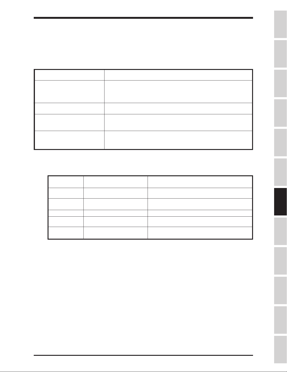
For your records, complete the following information about the drive with which this
manual was shipped.
H3 Model Number:
H3 Serial Number:
Date of Installation:
Inspected By:
Name of Application:
i
Page 4

TOSHIBA
INTRODUCTION
Thank you for purchasing the H3 adjustable speed drive. This adjustable frequency solid-state AC drive
features "True Torque Control" - Toshiba's 'vector algorithm' that enables motors to develop high starting
torque and compensates for motor slip. The H3 also features a multi-lingual forty-character LCD display,
RS232 port, dynamic braking transistor and ground fault, overload, and overcurent protection. These features, combined with built-in special control features such as PID, drooping, trim, and dancer control, make
the H3 suitable for a wide variety of applications that require unparalleled motor control and
reliability.
It is the intent of this operation manual to provide a guide for safely installing, operating, and maintaining the
drive. This operation manual contains a section of general safety instructions and is marked
throughout with warning symbols. Read this operation manual thoroughly before installing and operating
this electrical equipment.
All safety warnings must be followed to ensure personal safety.
Follow all precautions to attain proper equipment performance and longevity.
We hope that you find this operation manual informative and easy to use. For assistance with your H3, for
information on our free drive application school, or for information on Toshiba's complete line of motors,
adjustable speed drives, switchgear, instrumentation, uninterruptable power supplies, PLCs, and
motor control products, please call toll free (800) 231-1412 or write to our plant at: Toshiba International
Corporation, 13131 W. Little York Road, Houston, TX 77041-9990.
Again, thank you for your purchase of this product.
COPYRIGHT © [MARCH, 2008] TOSHIBA INTERNATIONAL CORPORATION
ii
Page 5
TOSHIBA
GENERAL SAFETY INSTRUCTIONS
Warnings
in this manual appear in either of two ways:
1)
Danger warnings
triangle which precedes the 3/16" high letters spelling the word "DANGER". The
Danger warning symbol is used to indicate situations, locations, and conditions that
can cause serious injury or death:
- The danger warning symbol is an exclamation mark enclosed in a
DANGER
2)
Caution warnings
triangle which precedes the 3/16" high letters spelling the word "CAUTION". The
Caution warning symbol is used to indicate situations and conditions that can cause
operator injury and/or equipment damage:
- The caution warning symbol is an exclamation mark enclosed in a
CAUTION
Other warning symbols may appear along with the
special hazards. These warnings describe particular areas where special care and/or procedures are
required in order to prevent serious injury and possible death:
1)
Electrical warnings
a triangle. The Electrical warning symbol is used to indicate high voltage locations and
conditions that may cause serious injury or death if the proper precautions are not
observed:
- The electrical warning symbol is a lighting bolt mark enclosed in
Danger
and
Caution
symbol and are used to specify
2)
For the purpose of this manual and product labels, a Qualified Person is one who is familiar with the
installation, construction, operation and maintenance of the equipment and the hazards involved.
This person must:
1) Carefully read the entire operation manual.
2) Be trained and authorized to safely energize, de-energize, clear faults, ground, lockout
3) Be trained in the proper care and use of protective equipment such as safety shoes,
4) Be trained in rendering first aid.
Explosion warnings
a triangle. The Explosion warning symbol is used to indicate locations and conditions
where molten, exploding parts may cause serious injury or death if the proper
precautions are not observed:
and tag circuits and equipment in accordance with established safety practices.
rubber gloves, hard hats, safety glasses, face shields, flash clothing, etc. in
accordance with established safety practices.
- The explosion warning symbol is an explosion mark enclosed in
iii
Page 6

TOSHIBA
CONTENTS
Disclaimer ...............................................................................................i
Introduction .............................................................................................. ii
General Safety Instructions.....................................................................iii
Contents ............................................................................................iv-vi
Section 1 Inspection/Storage/Disposal
Inspection of the New Unit......................................................................... 1-1
Storage .............................................................................................1-1
Disposal .............................................................................................1-1
PAGE
Section 2 Installation and Operation
Installation Safety Precautions ..................................................................2-1
Operating Safety Precautions.................................................................... 2-2
Confirmation of Wiring ...............................................................................2-3
Start-up and Test.......................................................................................2-4
Maintenance .............................................................................................2-4
Section 3 Specifications
230 Volt NEMA Type 1 Chassis Ratings ...................................................3-1
460 Volt NEMA Type 1 Chassis Ratings ...................................................3-1
Standard Specifications.............................................................................3-2
Section 4 Wiring
Standard Connection Diagrams ................................................................4-1
Selection of Main Circuit Wiring Equipment and
Standard Cable Sizes................................................................................4-3
Grounding .............................................................................................4-5
Application Notes: Motor Selection............................................................ 4-5
Connection Examples
Potentiometer Operation................................................................. 4-6
4-20 mA Reference Operation........................................................4-7
Keypad Reference and Remote Stop/Start ....................................4-8
RS232 Port .....................................................................................4-9
0-10 Volt Reference Operation ....................................................... 4-9
iv
Page 7

TOSHIBA
CONTENTS (cont'd)
Section 5 Jumper and Terminal Connections
Terminal Strip Board..................................................................................5-1
Control Board ............................................................................................5-2
Terminal Connections and Functions ........................................................ 5-3
Section 6 Operating Panel
Panel Layout ............................................................................................. 6-1
Keys and Functions...................................................................................6-2
Section 7 Keypad Functions
Local Mode .............................................................................................7-1
Forward/Rerverse Change ............................................................. 7-1
Jog .............................................................................................7-1
Coast Stop......................................................................................7-2
Programming Mode ...................................................................................7-2
Remote Mode............................................................................................7-2
ESTOP............................................................................................ 7-2
Other: Language Selection........................................................................7-2
Monitor Mode............................................................................................. 7-3
Monitoring "RR" Input Special Function..........................................7-4
Monitoring Pattern Run...................................................................7-4
PAGE
Section 8 Programming Charts
Fundamental Parameters #1 .....................................................................8-1
Fundamental Parameters #2 .....................................................................8-2
Panel Control Parameters .........................................................................8-3
Special Control Parameters.......................................................................8-4
Terminal Selection Parameters .................................................................8-5
Frequency Setting Parameters..................................................................8-8
Protection Parameters..............................................................................8-13
Pattern Run Control Parameters ..............................................................8-16
Feedback Parameters ..............................................................................8-22
Communication Setting Parameters.........................................................8-24
Industrial Application Parameters (Pump) ................................................8-26
Industrial Application Parameters (Fan) ...................................................8-26
Industrial Application Parameters (Conveyor) ..........................................8-26
Industrial Application Parameters (Hoist) .................................................8-26
Industrial Application Parameters (Textiles) .............................................8-26
v
Page 8

TOSHIBA
CONTENTS (cont'd)
Section 8 Programming Charts (cont'd)
Industrial Application Parameters (Machine Tools) ..................................8-26
AM/FM Terminal Adjustment Parameters................................................. 8-27
Utility Parameters .....................................................................................8-28
Motor Parameters.....................................................................................8-32
Parameter Tree ........................................................................................8-33
Section 9 Programming
Groups .............................................................................................9-1
Blinding .............................................................................................9-2
Search Function ........................................................................................9-2
Parameter Explanations ............................................................................ 9-3
Programming Examples ...........................................................................9-30
Section 10 Service
Requesting After Sales Service................................................................10-1
Parts Service Life .....................................................................................10-2
Troubleshooting........................................................................................10-3
How to Clear a Fault ......................................................................10-3
Drive Fault Displays and Explanations ..........................................10-3
Drive Warning Displays and Explanations.....................................10-7
PAGE
Section 11 Dimensions/Weights
Basic Dimensions .....................................................................................11-1
Shipping Weights......................................................................................11-3
Drive Options............................................................................................11-4
Keypad Cutout..........................................................................................11-5
Section 12 Index ............................................................................................12-1
vi
Page 9

TOSHIBA
SECTION 1: Inspection/Storage/Disposal
Inspection of the New Unit
Upon receipt of the H3, a careful inspection for shipping damage should be made. After uncrating:
1) Check the unit for loose, broken, bent or otherwise damaged parts due to
shipping.
2) Check to see that the rated capacity and the model number specified on the
nameplate conform to the order specifications.
Storage
1) Store in a well ventilated location and preferably in the original carton if the
inverter will not be used immediately after purchase.
2) Avoid storage in locations with extreme temperatures, high humidity, dust, or
metal particles.
Disposal
Please contact your state environmental agency for details on disposal of electrical components
and packaging in your particular area. Never dispose of electrical components via
incineration.
InspectionPrecautions
Specifications
Wiring
JumpersPanelKeypadParametersProgrammingServiceDimensionsIndex
1 - 1
Page 10

TOSHIBA
SECTION 2: Installation and Operation
Installation Safety Precautions
1) Install in a secure and upright position in a well ventilated location that is out of
direct sunlight. The ambient temperature should be between -10° C and 40° C.
2) Allow a clearance space of 8 inches (20 cm) for the top and bottom and 2 inches
(5 cm) on both sides. For models 2010-2270 and models 4015-4500, the top and bottom
clearance can be reduced to 4 inches (10 cm). This space will insure adequate ventilation.
Do not obstruct any of the ventilation openings.
3) Avoid installation in areas where vibration, heat, humidity, dust, steel particles,
or sources of electrical noise are present.
4) Adequate working space should be provided for adjustment, inspection and
maintenance.
5) Adequate lighting should be available for troubleshooting and maintenance.
6) A noncombustible insulating floor or mat should be provided in the area
immediately surrounding the electrical system where maintenance is required.
7) Always ground the unit to prevent electrical shock and to help
CAUTION
reduce electrical noise. A separate ground cable should be run
inside the conduit with the input, output, and control power
cables (See Grounding page 4-5).
THE METAL OF CONDUIT IS NOT AN ACCEPTABLE GROUND.
8) Use lockout/tagout procedures before connecting three phase power of the
correct voltage to input terminals L1, L2, L3 (R, S, T) and connect three phase
power from output terminals T1, T2, T3 (U, V, W) to a motor of the correct voltage
and type for the application. Size the conductors in accordance with
Main Circuit Wiring Equipment and Standard Cable Sizes
9) If conductors of a smaller than recommended size are used in parallel to share
current then the conductors should be kept together in sets i.e. U1, V1, W1 in
one conduit and U2, V2, W2 in another. National and local electrical codes
should be checked for possible cable derating factors if more than three power
conductors are run in the same conduit.
10) Install a molded case circuit breaker (MCCB) between the power source and the
inverter. Size the MCCB to clear the available fault current of the power source.
11) Use separate metal conduits for routing the input power, output power, and
control circuits.
12) Installation of drive systems should conform to the
regulations of the
regional or industry codes and standards.
13) If the factory provided enclosure is removed from the drive, then it must be
provided with an alternate enclosure before operating. The alternate enclosure
should be a minimum of NEMA 1.
Occupational Safety and Health Administration
Page 4-3.
National Electrical Code
Selection of
,
, all national,
2 - 1
Page 11
TOSHIBA
Installation Safety Precautions (cont'd)
14) Do not connect control circuit terminal block return connections marked CC to
inverter earth ground terminals marked GND(E). See
Diagrams
15) If a secondary Magnetic Contactor (MC) is used between the inverter output
and the load, it should be interlocked so the ST-CC terminals are disconnected
before the output contactor is opened. If the output contactor is used for bypass
operation, it must also be interlocked so that commercial power is never applied
to the inverter output terminals (U,V,W).
16) Power factor improvement capacitors or surge absorbers must not be installed
on the inverter's output.
17) Only qualified personnel should install this equipment.
Operating Safety Precautions
1) Do not power up the inverter until this entire operation manual is reviewed.
page 4-1 and
CAUTION
Standard Connection
Terminal Connections and Functions
CAUTION
page 5-3.
Precautions
Specifications
Wiring
JumpersPanelKeypadParametersProgrammingServiceDimensionsIndex Inspection
2) The input voltage must be within +/-10% of the specified input voltage. Voltages
outside of this permissible tolerance range may cause internal protection
devices to turn on or can cause damage to the unit. Also, the input frequency
should be within +/-2 Hz of the specified input frequency.
3) Do not use this inverter with a motor whose rated input is greater than the rated
inverter output.
4) This inverter is designed to operate NEMA B motors. Consult the factory before
using the inverter for special applications such as an explosion proof motor or
one with a repetitive type piston load.
5)
Do not touch any internal part with power applied to the inverter; first remove
the power supply from the drive and wait until charge LED (see page 5-1 for location)
is no longer illuminated. Charged capacitors can present a hazard even if source
power is removed. not touch any internal part with
the sou 6) DO NOT OPERATE THIS UNIT WITH ITS CABINET DOOR OPEN.
7) Do not apply commercial power to the output terminals T1 (U), T2 (V), or T3
(W) even if the inverter source power is off. Disconnect the inverter from the
motor before megging or applying bypass voltage to the motor.
DANGER
power applied to the inverter. First remove
2 - 2
Page 12

TOSHIBA
Operating Safety Precautions (cont'd)
8) Interface problems can occur when this drive is used in conjunction with
some types of process controllers. Signal isolation may be required to
prevent controller and/or drive malfunction (contact Toshiba or the process
controller manufacturer for additional information about compatibility and
signal isolation).
9) Do not open and then re-close a secondary magnetic contactor (MC) between
the drive and the load unless the drive is OFF (output frequency has
dropped to zero) and the motor is not rotating. Abrupt re-application of the
load while drive is on or while motor is rotating can cause drive damage.
10) Use caution when setting output frequency. Overspeeding a motor can decrease its
torque-developing ability and can result in damage to the motor and/or driven
equipment.
11) Use caution when setting the acceleration and deceleration time. Unnecessarily
short times can cause tripping of the drive and mechanical stress to loads.
12) Only qualified personnel should have access to the adjustments and
operation of this equipment. They should be familiar with the drive operating
instructions and with the machinery being driven.
CAUTION
13) Only properly trained and qualified personnel should be allowed to service
this equipment. See page iii.
14) Follow all warnings and precautions. Do not exceed equipment ratings.
Confirmation of Wiring
Make the following final checks before applying power to the unit:
1) Confirm that source power is connected to terminals L1, L2, L3 (R, S, T).
Connection of incoming source power to any other terminals will damage
the drive.
2) The 3-phase source power should be within the correct voltage and frequency
tolerances.
3) The motor leads must be connected to terminals T1, T2, T3 (U, V, W).
4) Make sure there are no short circuits or inadvertent grounds and tighten any
loose connector terminal screws.
CAUTION
2 - 3
Page 13
TOSHIBA
Start-Up and Test
Prior to releasing an electrical drive system for regular operation after installation,
the system should be given a start-up test by qualified personnel. This assures
correct operation of the equipment for reasons of reliable and safe performance. It is
important to make arrangements for such a check and that time is allowed for it.
When power is applied for the first time, the drive's parameters are set to the values
listed as "FACTORY SETTING" in the charts starting on page 8-1. If these settings are not
optimal for the application, program the desired settings before initiating a run. The
drive can be operated with no motor connected. Operation with no motor
connected or use with a small trial motor is recommended for initial adjustment or for
learning to adjust and operate the drive.
Maintenance
1) Use lockout/tagout procedures in accordance with local electrical codes
before performing any drive maintenance.
2) Periodically check the operating drive for cleanliness.
3) Do not use liquid cleaning agents.
CAUTION
Precautions
Specifications
Wiring
CAUTION
JumpersPanelKeypadParametersProgrammingServiceDimensionsIndex Inspection
4) Keep the heatsink free of dust and debris.
5) Periodically check electrical connections for tightness (with power off,
locked out, and with charge LED out (see page 5-1 for location)).
2 - 4
Page 14
TOSHIBA
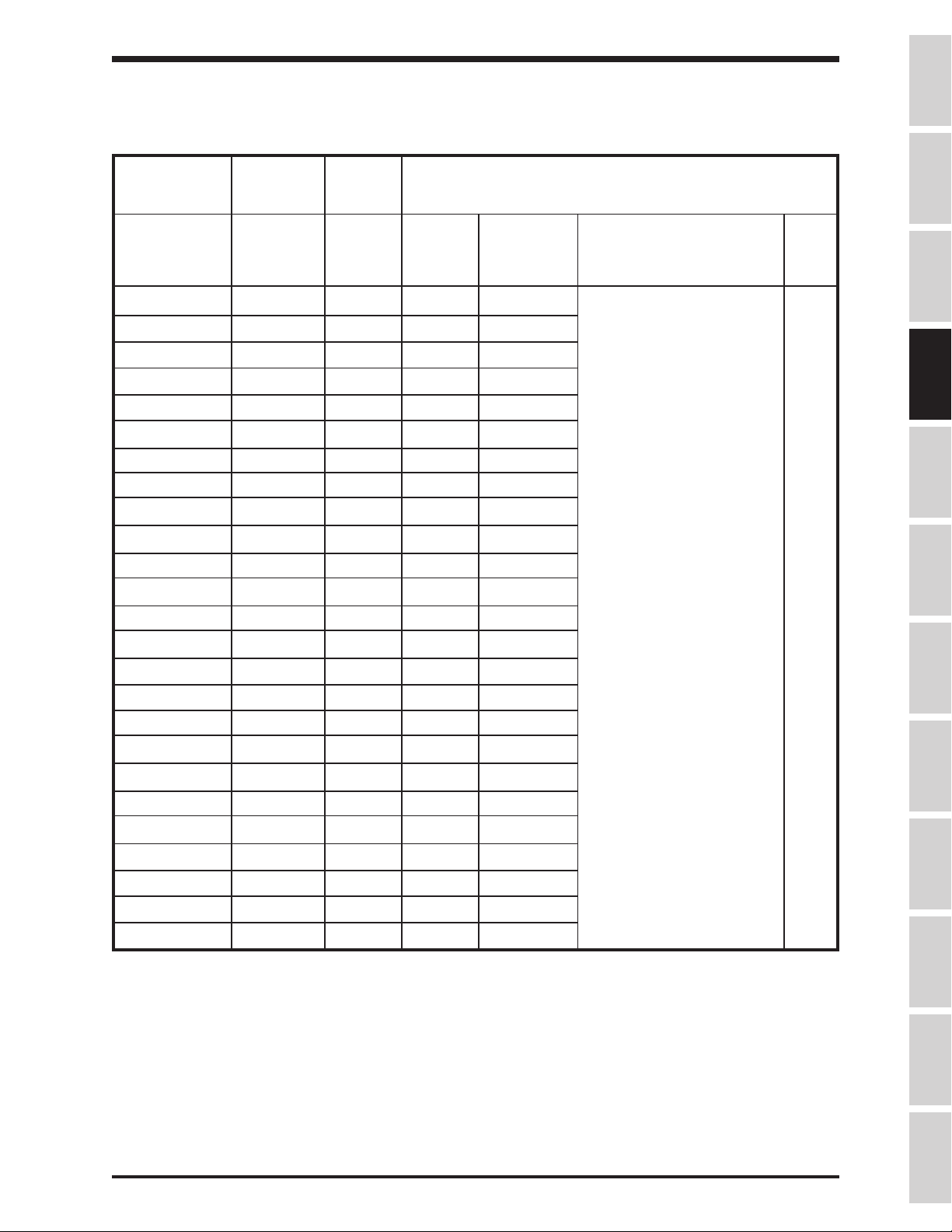
SECTION 3: Specifications
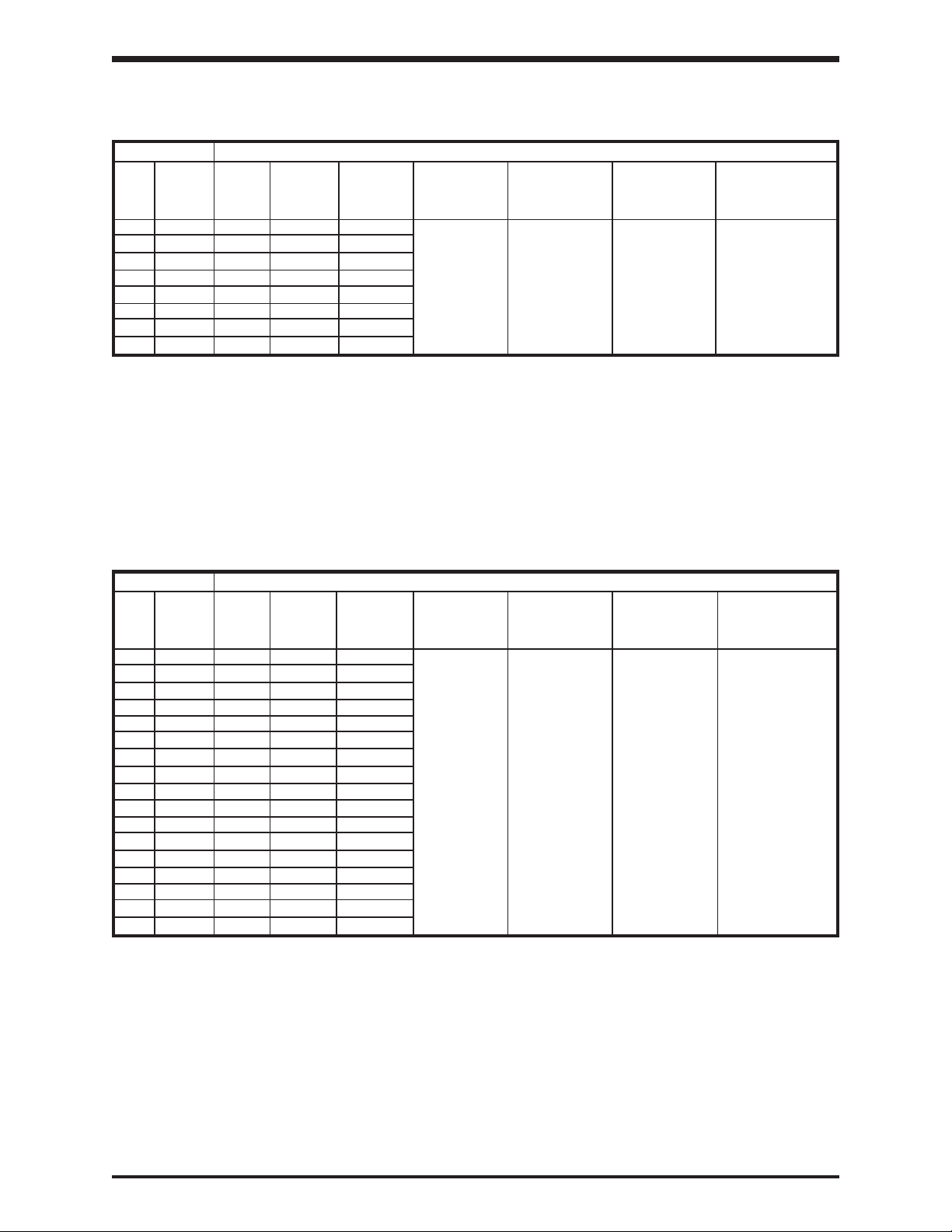
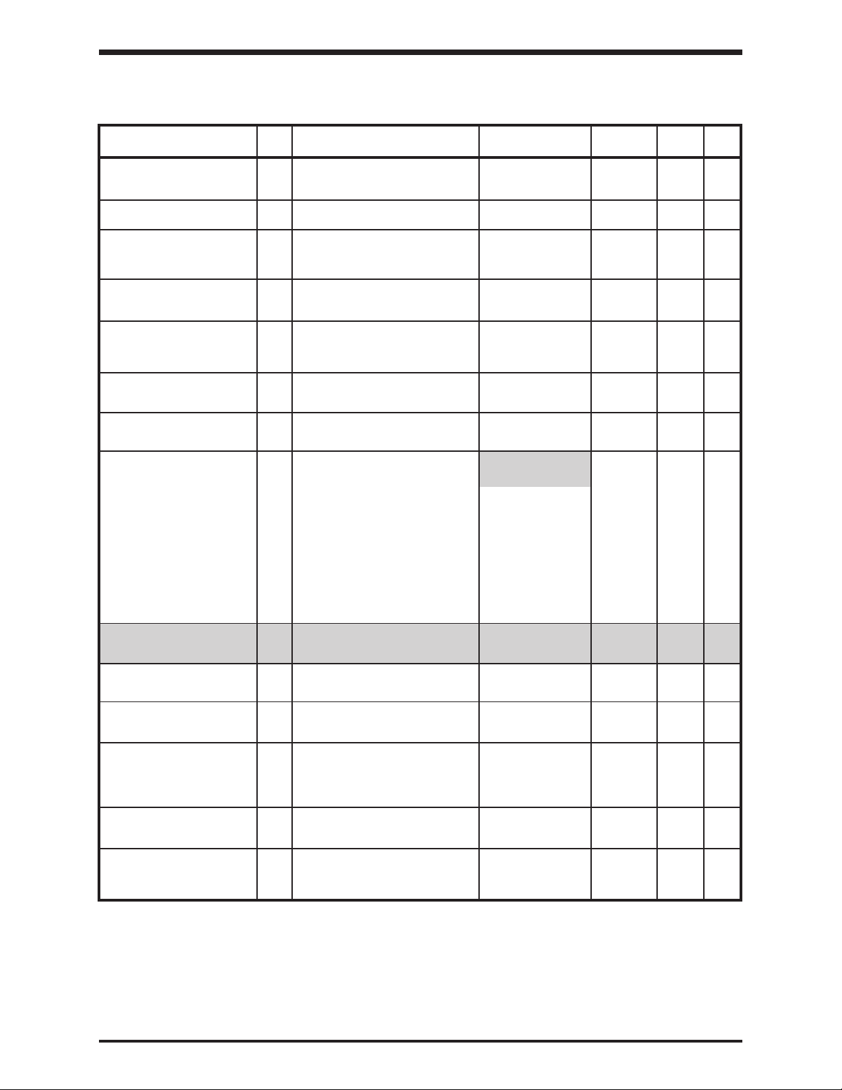
230 Volt NEMA Type 1 Chassis Standard Ratings
H3 STANDARD RATINGS
RATED MOTOR OUTPUT OUTPUT OVERLOAD MAIN CIRCUIT INPUT
KVA HP(KW) CURRENT VOLTAGE CURRENT INPUT POWER CONTROL
(see below)
MODEL
NOTES
2035 (1) 3.5 3/2.2 10.6 200-230V 120% FOR 200V/50Hz or NO EXTERNAL
2055 (1) 5.5 5/3.7 17 3-PHASE 60 SEC. 200-230V/60Hz CONTROL
2080 (1) 8 7.5/5.5 24.3
2110 (1) 11 10/7.5 33 CONTINUOUS
2160 (1) 16 15/11 46
2220 (1) 22 20/15 60
2270 (1) 27 25/18 75
2330 (1) 33 30/23 89
NOTES:
1) NEMA Type1 UL/CUL listing
(AMPS) 3-PHASE POWER
MAX VOLTAGE
110%
VOLTAGE +/- 10%
FREQ. +/- 2Hz
POWER SOURCE
REQUIRED
460 Volt NEMA Type 1 Chassis Standard Ratings
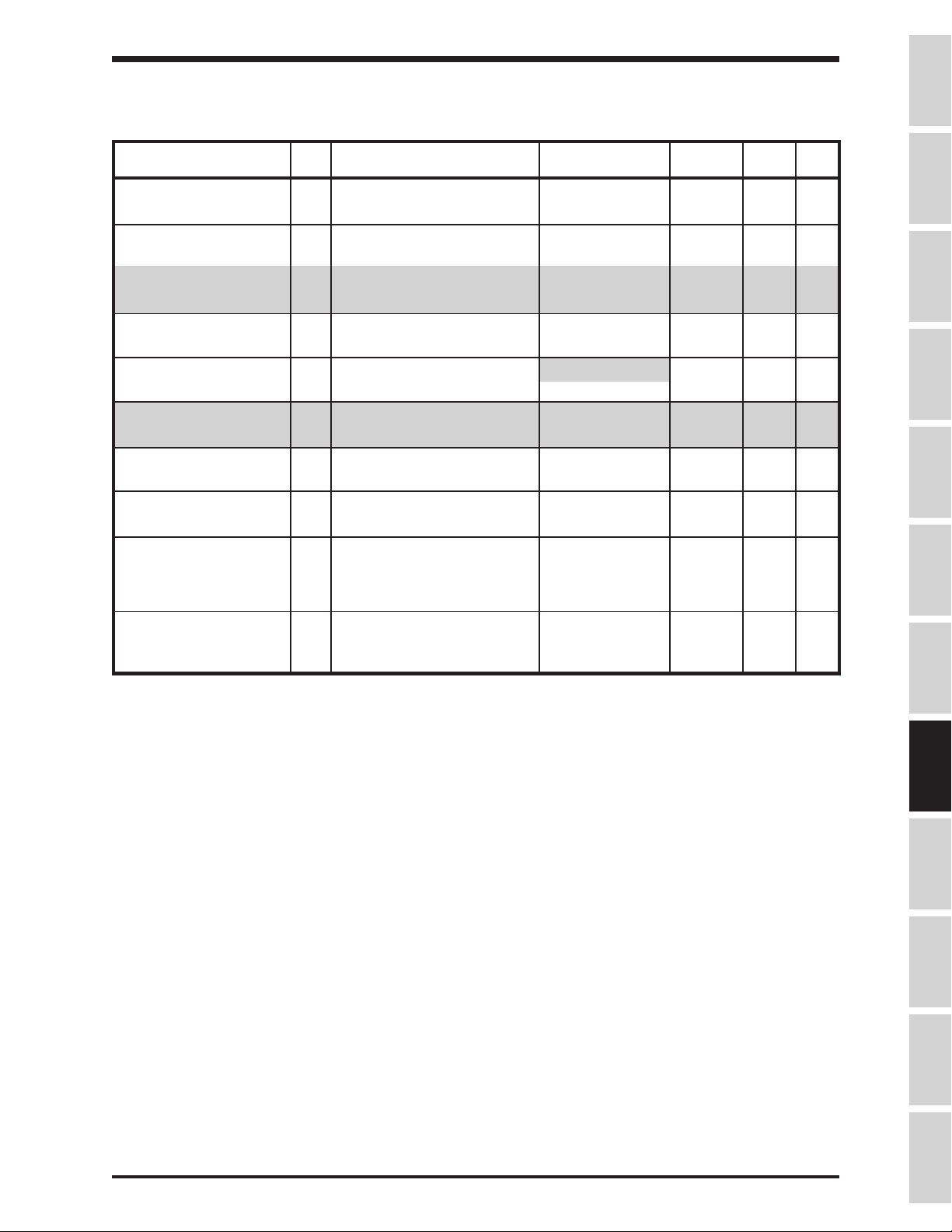
H3
RATED MOTOR OUTPUT OUTPUT OVERLOAD MAIN CIRCUIT INPUT
KVA HP(KW) CURRENT VOLTAGE CURRENT INPUT POWER CONTROL
(AMPS) 3-PHASE POWER
4055
(see below)
MODEL
NOTES
(1) 5.5 5/3.7 7.6 380-460V 120% FOR 380V/50Hz or NO EXTERNAL
4080 (1) 8 7.5/5.5 11 3-PHASE 60 SEC. 400-460V/60Hz CONTROL
4110 (1) 11 10/7.5 15
4160 (1) 16 15/11 22 CONTINUOUS
4220 (1) 22 20/15 28
4270 (1) 27 25/18.5 34
4330 (1) 33 30/22 40
4400 (1) 40 40/30 56
4500 (2) 50 50/37 65
4600 (2) 60 60/45 82
4750 (1) 75 75/55 104
410K (1) 100 100/75 124
412K (1) 125 125/90 156
415K (1) 150 150/110 180
420K (1) 200 200/150 240
425K (1) 250 250/185 300
430K (1) 300 300/220 360
NOTES:
STANDARD RATINGS
MAX VOLTAGE
110%
VOLTAGE +/- 10%
FREQ. +/- 2Hz
POWER SOURCE
REQUIRED
1) NEMA Type 1 UL/CUL listing.
3 - 1
Page 15
TOSHIBA
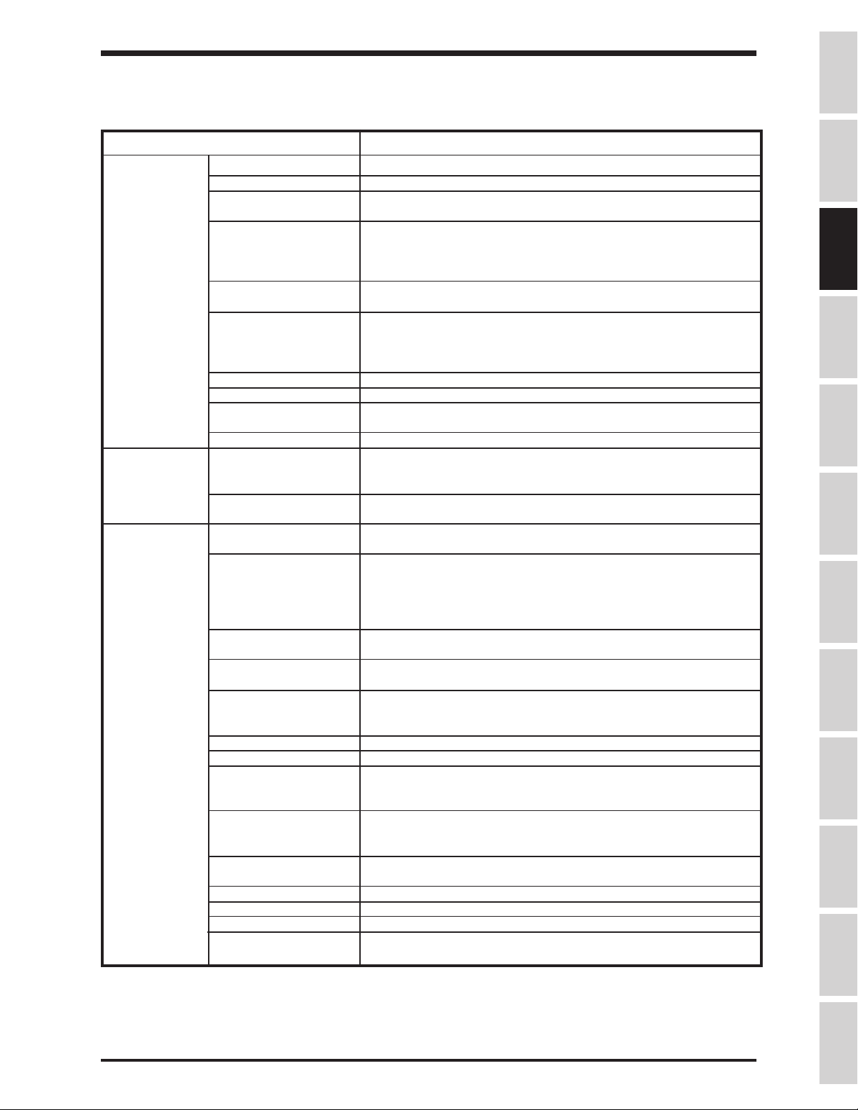
Standard Specifications
ITEM STANDARD SPECIFICATIONS
Principal Control System Sinusoidal PWM control
Control Output voltage regulation Same as power line.
Specifications Output frequency 0.01 to 400 Hz (0.1 to 80Hz default setting)*. 800 Hz operation
possible.
Frequency setting 0.1Hz from operating panel input (60Hz base), 0.01Hz from analog
input (60Hz base, 12-bit/0 to 10Vdc), 0.01Hz from computer interface
(60Hz base)
Precautions
Frequency accuracy Analog input: ±0.2% of the maximum output frequency (25°C±10°C),
Digital input: ±0.01% (25°C±10°C)
Voltage/frequency Constant V/f, variable torque, automatic torque boost, True Torque
characteristics Control and automatic energy-saving control/maximum voltage
frequency adjustment (25 to 400Hz), torque boost adjustment
(0 to 30%), start-up frequency adjustment (0 to 10Hz).
PWM carrier frequency Adjustable between 0.5 and 10kHz
Transistor type Insulated gate bipolar (IGBT)
Output voltage regulation Drive can be programmed to fix max. output volts, let max. float with
input voltage, or set max. to input voltage sensed at power-up.
Dynamic braking
Frequency Input signals 3k ohms potentiometer (1k ohm to 10k ohm-rated potentiometer
Set point control (PID) Proportional gain, integral gain, anti-hunting gain, lag time constant,
Operating Accel/decel time 0.1 to 6000 secs, accel/decel time 1 or 2 selection, accel/decel
functions pattern selection
Forward or reverse run Forward run when F-CC closed (default); reverse run when R-CC
Jogging run Jog run from panel with JOG mode selection. Terminal
Multispeed run Set frequency plus 15 preset speeds possible with combinations of
Retry When a protective function is activated, the system checks main
Soft stall Automatic load reduction during overload (Default setting: OFF).
Automatic restart A coasting motor can be smoothly restarted (Default setting: OFF).
Pattern Run 4 groups of 8 patterns each can be set to the 15 preset speed values.
DC injection braking Braking starting frequency adjustment (0 to 120Hz), braking current
Upper/Lower limit Limits the frequency between the set values (0 to max. frequency).
Frequency jump 3 jump frequency settings (each with unique band settings)
Edit function Easy access user group containing all changed parameters
Blind function Select to display needed parameter groups and parameters
User-defined defaults User's parameter values can be saved into a default library. User
Feature not available in H3 drives above 30 HP.
can be connected). 0 to 10Vdc (Zin=33k ohm), ±10 Vdc (Zin=67k
ohm), +/-5 Vdc (Zin=34k ohm), 4 to 20mAdc (Zin=500 ohm)
and PID error limit adjustments.
closed (default); reverse run when both closed (default); coast-stop
when ST-CC opened (default); emergency coast stop by a
command from operating panel or terminal block; 3-wire control and
motorized speed pot programmable functions.
block operation possible with parameter settings.
CC, SS1, SS2, SS3, and SS4 (default functions).
circuit devices, and attempts to restart. Settable to a maximum
of 10 times; wait time adjustment (0 to 10 secs)
A maximum of 32 different patterns can be run; terminal block
control/repetitive run possible.
adjustment (0 to 100%), braking time adjustment (0 to 10secs),
emergency stop braking function, motor shaft stationary control.
Can be indicated via output contact closure.
can then default drive to Toshiba's values or to the user's own.
Specifications
Wiring
JumpersPanelKeypadParametersProgrammingServiceDimensionsIndex Inspection
* Consult the factory for applications above 80 Hz.
3 - 2
Page 16
TOSHIBA
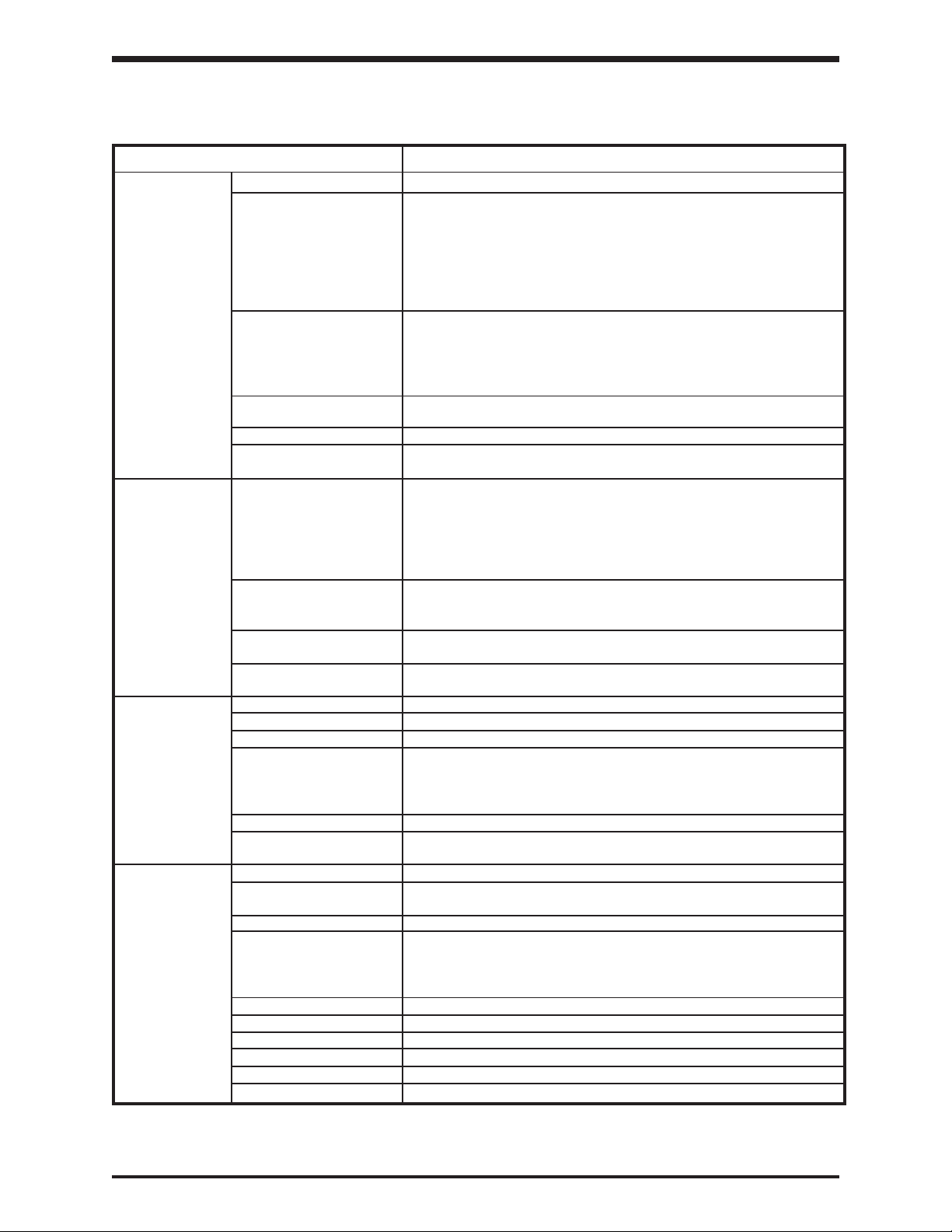
Standard Specifications (cont'd)
ITEM STANDARD SPECIFICATIONS
Display Interface 2-line backlit display LCD 20 characters per line
Fault display Overcurrent, overvoltage, heatsink overheat, load-side short-circuit,
load-side ground fault, inverter overload, stator overcurrent during
start-up, load-side overcurrent during start-up, EEPROM error, RAM
error, ROM error, communication error, (dynamic braking unit
overcurrent/overload), (emergency stop), (undervoltage), (low
current), (overtorque), (open output phase), (motor overload). Items
in parenthesis can be selected or deselected.
Monitor functions Terminal input/output status, forward/reverse, frequency setting
value, output frequency, output current, output voltage, input power,
output power, torque current, cumulative run time, past faults,
excitation current, DBR overload ratio, inverter overload ratio, motor
overload ratio, PID feedback value, DC voltage.
Selectable units display Can scale frequency display.
Selection of display of current in amps or %, voltage in V or %.
LED charge indicator Indicates that the main circuit capacitors are charged
LED local/remote Mounted in LOCAL/REMOTE key. Indicates local (keypad) or
indicator remote (terminal) control
Inverter/Motor Protective functions Soft-stall, current limit, overcurrent, overvoltage, short-circuit at load,
load-side ground fault, undervoltage, momentary power failure,
regeneration power ride-through, electronic thermal overload
protection, main circuit overcurrent at start-up, load-side overcurrent
during start-up, DBR resistor overcurrent/overload, heatsink over
heat, emergency stop, open output phase.
Electronic thermal Drive's motor overload protection for motor can be adjusted for motor
characteristics rated amperage. Motor overload has adjustable speed sensitivity.
Soft stall on/off. Motor 150% time programmable.
Reset Fault reset via keypad, remote contact closure, or programming drive
retry. Cycling power also resets fault (fault display can be maintained)
Regeneration power Some H3 ratings can use regen energy from motor to maintain
ride-through control operation during brown-outs.
Output signals Fault detection signal NC/NO form C contact (250VDC, 2A)
Low speed/reach signals Dry contacts (250VDC, 2A)
Upper limit/lower limit Dry contacts (250VDC, 2A)
Programmable meter Pre-compensation reference frequency, post-compensation output
output signals frequency, frequency setting value, output current, DC voltage,
output voltage, torque current, excitation current, PID feedback value,
motor/inverter/DBR overload ratio, input/output power.
Pulse-train frequency Open collector output (max. 24 Vdc, 50mA)
Communication functions RS232C equipped as standard ( connector: modular 6P), RS485,
TOSLINE-F10, TOSLINE-F20, RIO, DN, and MB+ are options.
Enclosure Type NEMA Type 1
Cooling method Forced air cooling . Fan can be automatically stopped when not
necessary for extended fan life.
Color Sherwin Williams Precision Tan #F63H12
Service environment Indoor. Consult factory for elevations above 1000m (requires derate).
For example, at 2000m, derate drive FLA by 11%.
Must not be exposed to direct sunlight, corrosive and/or explosive
gases or mists, fibers and dusts.
Ambient temperature From -10°C to 40°C (14°F to 104°F).
Relative humidity 20 to 95% maximum (non-condensating)
Vibration 5.9 m/s (0.5G) maximum (10 to 55Hz)
Climatic class 3K3
Polution degree 2
IP rating 2X
2
3 - 3
Page 17
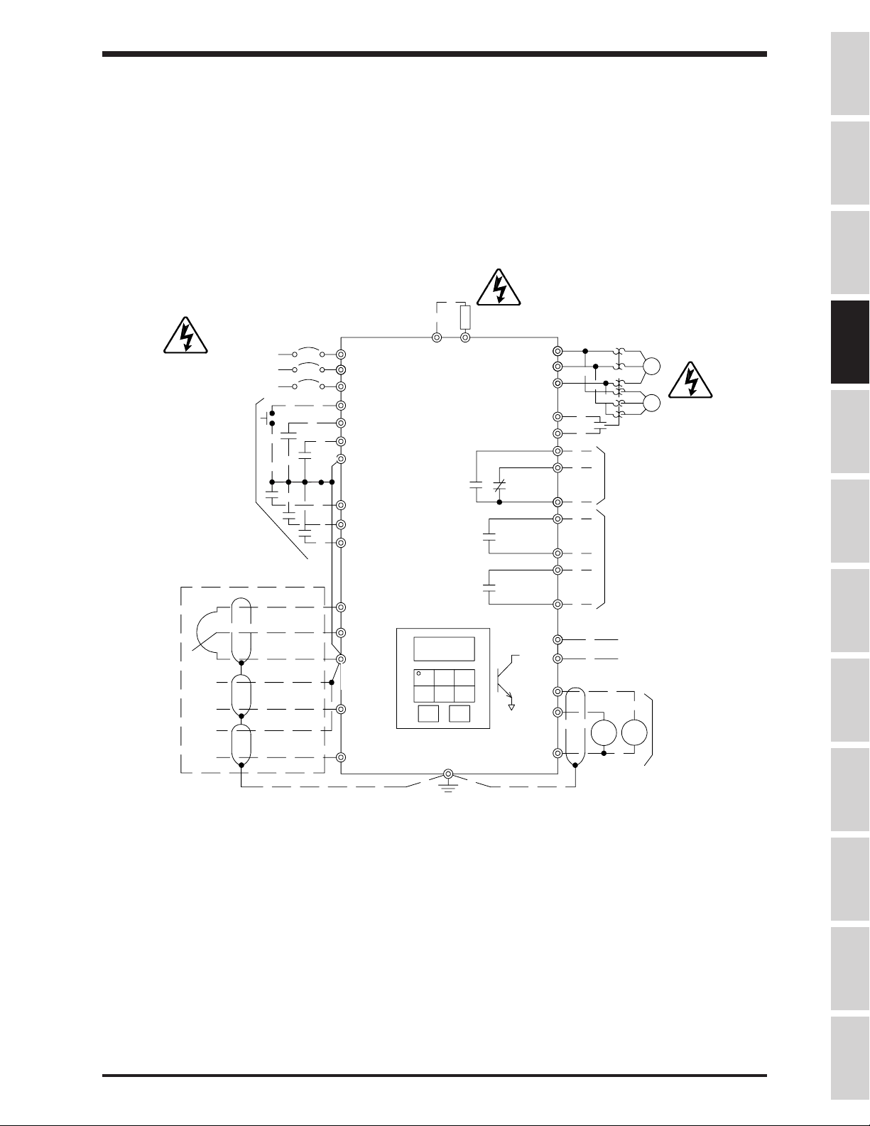
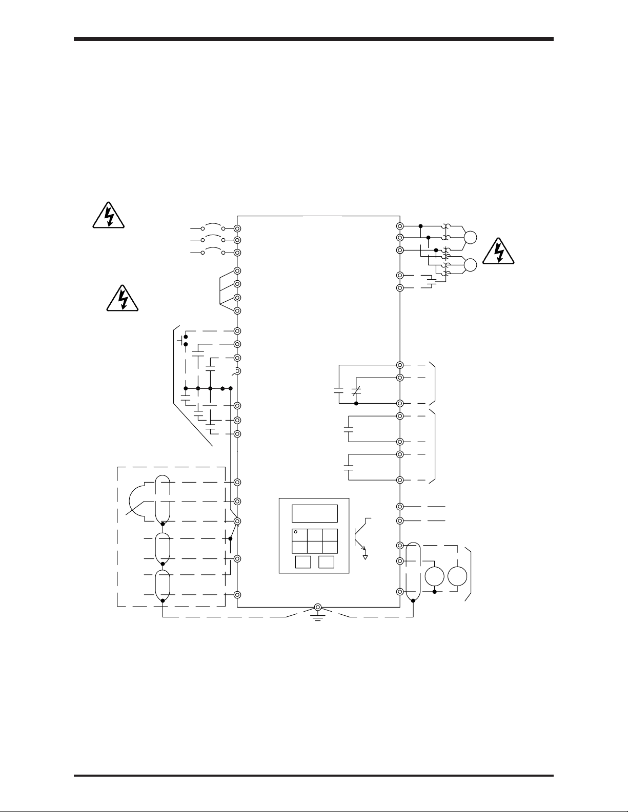
SECTION 4: Wiring
Standard Connection Diagrams
MCCB
INPUT POWER SUPPLY
(see notes 1 and 2 below)
PROGRAMMABLE
SIGNAL INPUT
PROGRAMMABLE
ANALOG INPUT
Potentiometer
-
AUTO
REF.
+
-
AUTO
REF.
+
TOSHIBA
TOSVERT-130H3
STANDARD CONNECTION
MODEL 2035 TO 2330
MODEL 4055 TO 4330
DBR
L1(R)
L2(S)
L3(T)
RES
F
R
ST
S1
S2
S3
DIGITAL
PP
OPERATION PANEL
RR
CC
IV
RX
PA PB
(see note 3 below) S4
GND(E)
T1(U)
T2(V)
T3(W)
CC
FLA
FLB
FLC
R/CH-A
R/CH-C
LOW-A
LOW-C
P24
FP
FM
AM
CC
M
M
PROGRAMMABLE
OUTPUT CONTACTS
250V, 2A MAX
PROGRAMMABLE
OUTPUT CONTACTS
250V, 2A MAX
50mA MAX
PULSE OUTPUT
+ +
AM
PROGRAMMABLE
SIGNAL OUTPUT
FM
0-1mA or 4-20mA
Precautions
Specifications
Wiring
JumpersPanelKeypadParametersProgrammingServiceDimensionsIndex Inspection
NOTES:
1.) For drive models 2035 through 2330 use input power supply of 200VAC, 50Hz or
200-230VAC, 60Hz.
2.) For drive models 4055 through 4330 use input power supply of 380VAC, 50Hz or
400-460VAC, 60Hz.
3.) As an example, the "S4" terminal is shown above as an EMERGENCY OFF input. See
Section 8 for information on how to program the drive for this and other functions.
4 - 1
Page 18
Standard Connection Diagrams (cont'd)
STANDARD CONNECTION
MODEL 4400 TO 430K
MCCB
INPUT POWER SUPPLY
(set by input power selection)
INPUT POWER SELECTION
415/460V-50/60Hz
400/440V-50/60Hz
380V-50Hz
L1(R)
L2 (S)
L3 (T)
R41/46
R40/44
R38
RJ
TOSHIBA
TOSVERT-130H3
(see note 1 below) S4
T1(U)
T2 (V)
T3 (W)
CC
M
M
PROGRAMMABLE
SIGNAL INPUT
PROGRAMMABLE
ANALOG INPUT
Potentiometer
-
AUTO
REF.
+
-
AUTO
REF.
+
RES
F
R
ST
S1
S2
S3
DIGITAL
PP
OPERATION PANEL
RR
CC
IV
RX
GND(E)
FLA
FLB
FLC
R/CH-A
R/CH-C
LOW-A
LOW-C
P24
FP
FM
AM
CC
PROGRAMMABLE
OUTPUT CONTACTS
250V, 2A MAX
PROGRAMMABLE
OUTPUT CONTACTS
250V, 2A MAX
50mA MAX
PULSE OUTPUT
+
AM FM
PROGRAMMABLE
+
SIGNAL OUTPUT
0-1mA or 4-20mA
NOTE:
1.) As an example, the "S4" terminal is shown above as an EMERGENCY OFF input. See
Section 8 for information on how to program the drive for this and other functions.
4 - 2
Page 19
TOSHIBA
Selection of Main Circuit Wiring Equipment and Standard Cable Sizes
Drive circuit breaker (FLA x 1.25) ** Typical cable size (AWG)
Model Number rating (A) and Lug frequency meter, ammeter signal
H3-2035 20 13.3 #14 24-12 / 24-12
H3-2055 30 21.3 #14 24-12 / 24-12
H3-2080 50 30.4 #10 24-8 / 24-8
H3-2110 70 41.3 #8 18-2 / 18-2
H3-2160 90 57.5 #6 18-2 / 18-2
H3-2220 100 75.0 #4 18-2 / 18-2
H3-2270 125 93.8 #3 18-2 / 14-2/0
H3-2330 150 111.3 #2 6-250 / 6-250
H3-4055 15 9.5 #14 24-12 / 24-12
H3-4080 30 13.8 #14 24-8 / 24-8
H3-4110 30 18.8 #14 24-8 / 24-8
H3-4160 40 27.5 #10 18-2 / 14-2
H3-4220 50 35 #8 18-2 / 14-2
H3-4270 70 42.5 #8 18-2 / 14-2
* Molded case Ampacity
(MCCB)
Amp Main power Input and Output Frequency command input, Other
(A) motor load Wire Capacity circuits
3-core shield cable #18
(speed reference)
2-core shield cable
#20
Precautions
Specifications
Wiring
JumpersPanelKeypadParametersProgrammingServiceDimensionsIndex Inspection
H3-4330 90 50 #6 18-2 / 14-2
H3-4400 100 70 #4 18-2 / 14-2
H3-4500 100 81.3 #3 18-2 / 14-2
H3-4600 125 102.5 #2 6-250 / 6-250
H3-4750 175 130.0 #1 6-250 / 6-250
H3-410K 200 155 #2/0 6-250 / 6-250
H3-412K 225 195 #4/0 6-250 / 6-250
H3-415K 300 225 *** 2 (#2/0) 6-250 / 6-250
H3-420K 350 300 *** 2 (#2/0) 6-250 / 6-250
H3-425K 400 375 *** 2 (#4/0) 6-250 / 6-250
H3-430K 600 450 *** 2 (#250) 6-250 / 6-250
See page 4-4 for notes.
4 - 3
Page 20

TOSHIBA
Selection of Main Circuit Wiring Equipment and Standard Cable Sizes (cont'd)
* The customer supplied Molded Case Circuit Breaker (MCCB) or Magnetic Circuit
Protector (MCP) should be coordinated with the available short circuit current. The
drives are rated for output short circuit fault currents of 200,000A (in all horsepowers).
The selection of breakers for this table is in accordance with 1987 NEC Article 430.
** Wire sizing is based upon NEC table 310-16 or CEC Table 2 using 75 deg C cable, an
ambient of 30 deg C, cable runs for less than 300 FT., and copper wiring for not more
than three conductors in raceway or cable or earth (directly buried). The customer
should consult the NEC or CEC wire Tables for his own particular application and wire
sizing.
*** Use two parallel conductors instead of a single conductor (this will allow for the proper
wire bending radius within the cabinet). Use separate conduits for routing parallel
conductors. This prevents the need for conductor derating (see note 3 this page).
Notes:
1.) Contacts used to connect drive terminals should be capable of switching low
current signals (i.e. 5 mA).
2.) The drive has internal overload protection which has been calibrated and
certified by Underwriters Laboratories Inc. and does not require external motor
overload protection.
3.) When wiring with parallel conductors, the conductors should be kept together in
phase sets with U1, V1, W1 in one conduit and parallel conductors U2, V2, W2
in another conduit. The ground conductor should be in one of these conduits.
4) Twisted pair wiring should be used for external meters connected to AM and FM
terminals.
5) For multiple motor applications, a magnetic only MCP should be replaced
by a thermal magnetic MCCB. The MCCB should be sized according to (1.25 X
largest motor full load amps) + sum of all other motor full load amps to meet
National
Applications featuring multiple motors on one drive require overload protection for
each motor.
CAUTION
Electric Code (NEC) or Canadian Electrical Code (CEC) requirements.
Turn off power to the drive before making any wiring
changes to the analog output circuits.
CAUTION
Use separate conduits for routing incoming power, power
to motor, and control conductors. Use no more than three
power conductors and a ground conductor per conduit.
4 - 4
Page 21
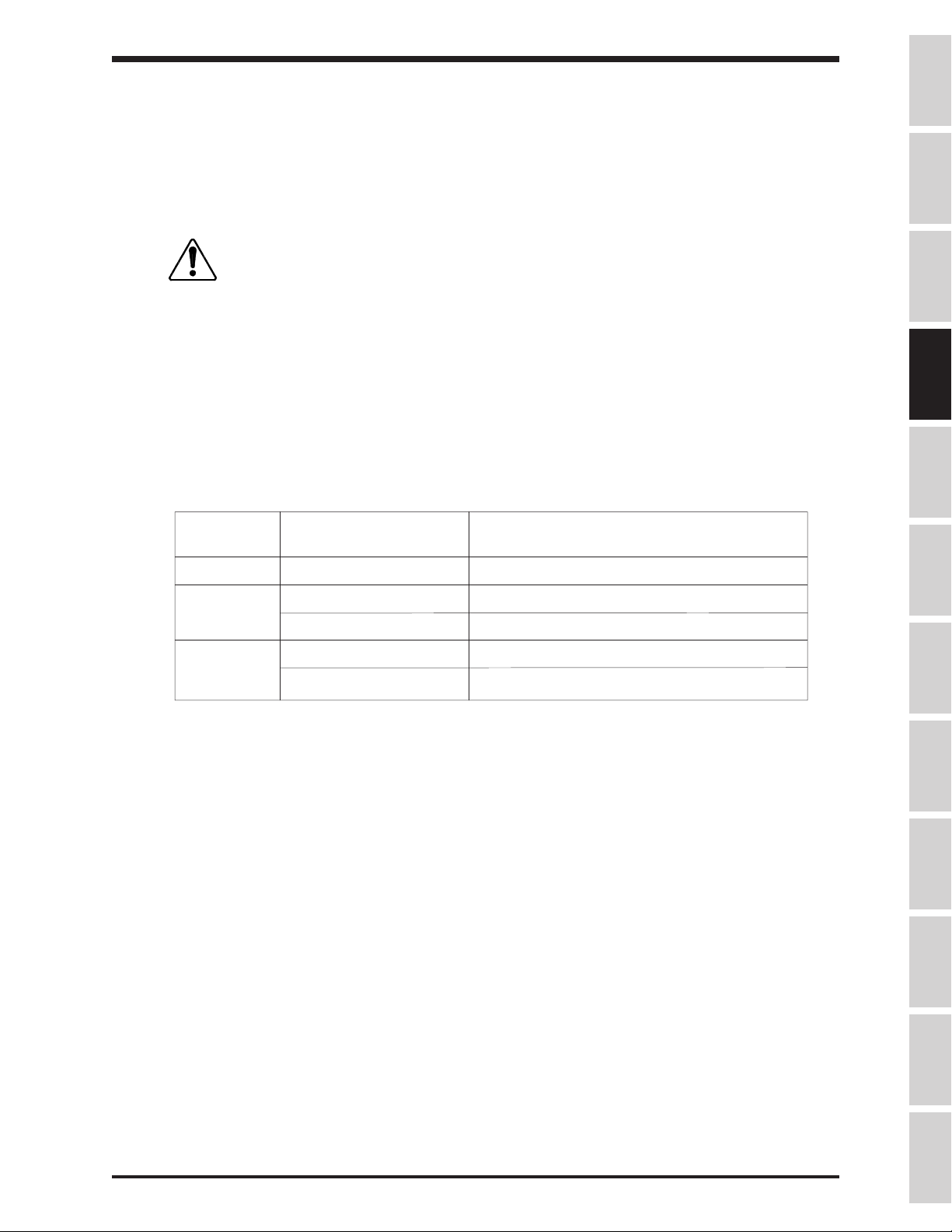
Grounding
The inverter must be grounded in accordance with Article 250 of the National Electrical
Code or Section 10 of the Canadian Electrical Code, Part I and the grounding conductor
should be sized in accordance with 1996 NEC Table 250-95 or CEC, Part I Table 16. See
Installation Safety Precautions notes 7 and 14.
TOSHIBA
Precautions
Motor Selection
1) Exceeding the peak voltage rating or the rise time allowable of the motor insulation
AC Motor
Voltage
230 V
460 V
575 V
460 V
575 V
CAUTION
system will reduce the life expectancy. To insure good motor insulation life, consult
with the motor supplier as to determine motor insulation ratings and allowable maximum
output lead distance. Long lead lenghts between the motor and the drive may require
filters to be added to the drive output.
Suggested Maximum Output Lead Distance
Conduit is not a suitable ground for the inverter.
1
PWM Carrier
Frequency
All
< = 5 kHz
> 5 kHz
< = 5 kHz
> 5 kHz
NEMA MG-1-1998 Section IV
Part 31 Compliant Motors
1000 ft.
600 ft.
300 ft.
200 ft.
100 ft.
2
Specifications
Wiring
JumpersPanelKeypadParametersProgrammingServiceDimensionsIndex Inspection
1
For lead lengths that exceed suggested maximum contact Toshiba for application
assistance.
2
Toshiba EQP III, III-XS & EQP III-841 motors incorporate an insullation system that
is in compliance with NEMA MG-1-1998 Section IV Part 31.
2) Bearing Considerations:
A. Motors operating from adjustable speed drive power sources tend to operate at
higher temperatures which may increase the need for more frequent lubrication
cycles.
4 - 5
Page 22
TOSHIBA
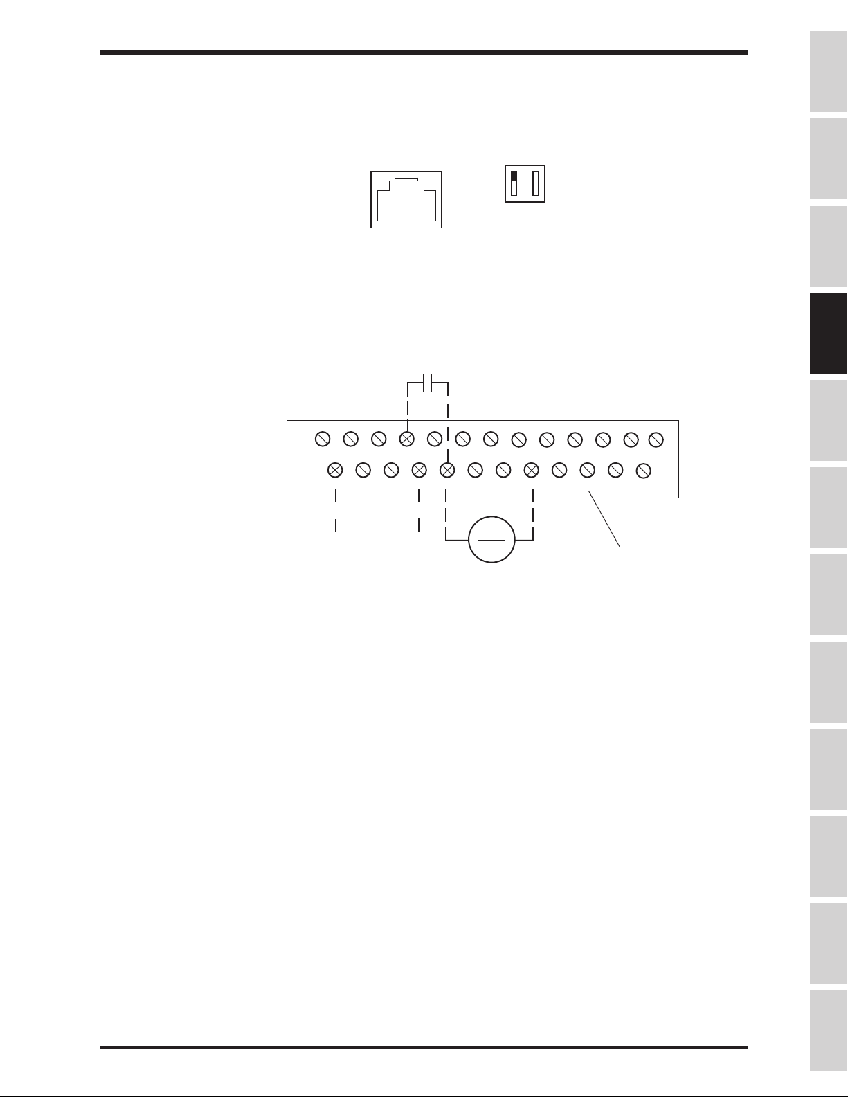
Connection Examples: Potentiometer Operation
Wiper
(usually middle terminal)
stop/start
P24 RES RR F R S1 S2 S3 S4
To run from a pot, the H3 must have:
1) Drive enable ("ST"-"CC" made)
2) Direction command ("F" or "R" to "CC" made)
3) Frequency reference ( wiper from pot is read via "RR" terminal )
4) LOCAL/REMOTE LED off (puts drive in remote mode).
Toggle the LOCAL/REMOTE button on keypad to turn LED off (with drive stopped).
Notes:
1) Use a 3K ohm pot (1 to 10 K ohms will work).
2) The drive will accel to commanded frequency when "F" or "R" to "CC" is made.
3) The drive will decel to 0.0 Hz when "F" or "R" to "CC" is broken.
4) Motor will coast to a stop if "ST" to "CC" is broken.
5) The above information applies to a H3 with factory default programming.
RCHARCHCLOWALOW
ST FM AM CC CC RX PP IV FP FLC FLB FLA
Terminal Block
C
4 - 6
Page 23
TOSHIBA
Connection Examples: 4 - 20mA Reference Operation
Phone Jack on Control Board
I 5
Dipswitch
V 10
stop/start
P24 RES RR F R S1 S2 S3 S4
ST FM AM CC CC RX PP IV FP FLC FLB FLA
( - )
>
(+)
RCHARCHCLOWALOW
4-20 mA Reference
Precautions
Specifications
Wiring
JumpersPanelKeypadParametersProgrammingServiceDimensionsIndex Inspection
C
Terminal Block
To follow a 4-20 mA signal, the H3 must have:
1) "IV" dipswitch to the right of phone jack on control board (immediately under keypad) set to "I"
position. "5/10" dipswitch has no effect in this scenario.
1) Drive enable ("ST"-"CC" made)
2) Direction command ("F" or "R" to "CC" made)
3) Frequency reference ( 4-20mA signal at "IV" terminal )
4) LOCAL/REMOTE LED off ( puts drive in remote mode)
Toggle the LOCAL/REMOTE button on keypad to turn LOCAL/REMOTE LED off.
Notes:
1) The drive will accel to the commanded frequency when "F" or "R" to "CC" is made.
2) The drive will decel to 0.0 Hz when "F" or "R" to "CC" is broken.
3) Motor will coast to a stop if "ST" to "CC" is broken.
4) The above information applies to a H3 with factory default programming.
5) Do not connect "CC" to ground.
4 - 7
Page 24
TOSHIBA
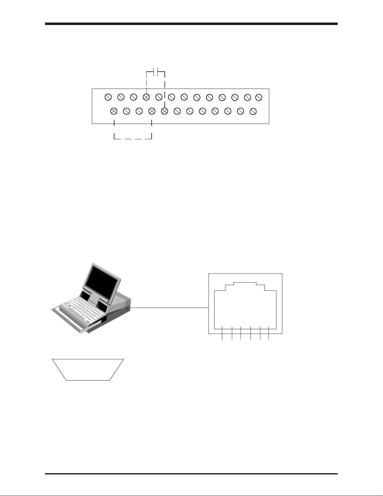
Connection Examples: Keypad Frequency Reference and Remote Stop/Start
dry contact (stop/start)
P24 RES RR F R S1 S2 S3 S4
ST FM AM CC CC RX PP IV FP FLC FLB FLA
RCHARCHCLOWALOW
C
To follow a local (keypad) reference with a remote stop/start, the H3 must have:
1) Drive enable ("ST"-"CC" made)
2) Direction command ("F" or "R" to "CC" made)
3) Frequency reference: Adjust on keypad with arrows. Press READ/WRITE to enter.
4) LOCAL/REMOTE LED off ( puts drive in remote mode)
Toggle the LOCAL/REMOTE button on keypad to turn LED off.
5) Programming: Set Item 282, FREQUENCY MODE SELECTION to "2". See page 8-28.
Notes:
1) The drive will accel to the commanded frequency when "F" or "R" to "CC" is made.
2) The drive will decel to 0.0 Hz when "F" or "R" to "CC" is broken.
3) Motor will coast to a stop if "ST" to "CC" is broken.
Connection Examples: RS232 Port
Pinout for G3 RJ11 RS232 port
Terminal Block
Pinout for DB-9 on computer
(5) (4) (3) (2) (1)
(9) (8) (7) (6)
( looking head-on at male connector
that plugs into computer )
Notes:
1) Free RS232 programming/monitoring software is available from Toshiba. Contact your distributor for a
copy and manual.
2) Do not insert/remove the phone plug into/from the H3 port when drive is powered.
3) Common 6 conductor phone cord can be used with an adaptor (6 conductor RJ11 female to DB9 female).
The adapter is available from your Toshiba distributor or local electrical supply house.
4) "ST"-"CC" must be made.
<
>
6 5 4 3 2 1
( facing front of G3 )
Connect DB9 pin 5 to RJ11 pin 3
Connect DB9 pin 3 to RJ11 pin 4
Connect DB9 pin 2 to RJ11 pin 2
Connect DB9 pin 7 to RJ11 pin 6
Connect DB9 pin 8 to RJ11 pin 1
Short DB9 pin 6 to DB9 pin 4
DB9 pin 1 and 9 and RJ11 pin 5 not used
4 - 8
Page 25
TOSHIBA
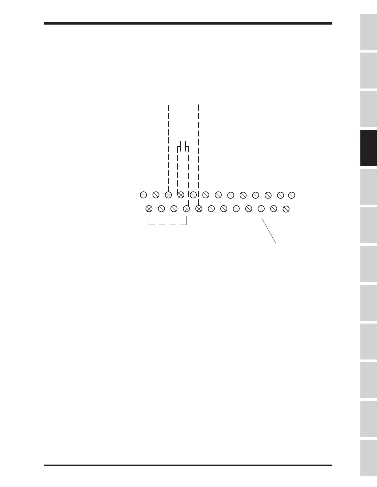
Connection Examples: 0-10 volt Reference Operation
0-10 V
Reference
(+) ( - )
<
stop/start
Precautions
>
Specifications
Wiring
P24 RES RR F R S1 S2 S3 S4
ST FM AM CC CC RX PP IV FP FLC FLB FLA
To run from a 0-10 V reference, the H3 must have:
1) Drive enable ("ST"-"CC" made)
2) Direction command ("F" or "R" to "CC" made)
3) Frequency reference ( 0-10 V signal applied to "RR" terminal )
4) LOCAL/REMOTE LED off (puts drive in remote mode).
Toggle the LOCAL/REMOTE button on keypad to turn LED off.
Notes:
1) The drive will accel to commanded frequency when "F" or "R" to "CC" is made.
2) The drive will decel to 0.0 Hz when "F" or "R" to "CC" is broken.
3) Motor will coast to a stop if "ST" to "CC" is broken.
4) The above information applies to a H3 with factory default programming.
5) Do not connect "CC" to ground.
RCHARCHCLOWALOW
C
Terminal Block
JumpersPanelKeypadParametersProgrammingServiceDimensionsIndex Inspection
4 - 9
Page 26
TOSHIBA
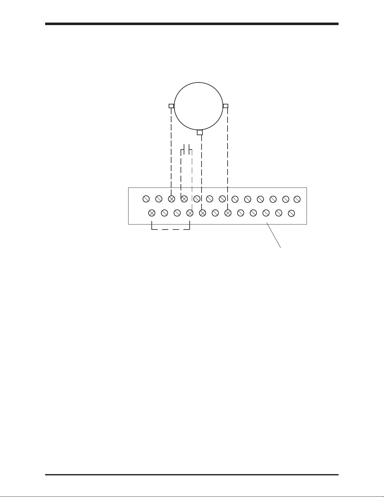
SECTION 5: Jumper and Terminal Connections
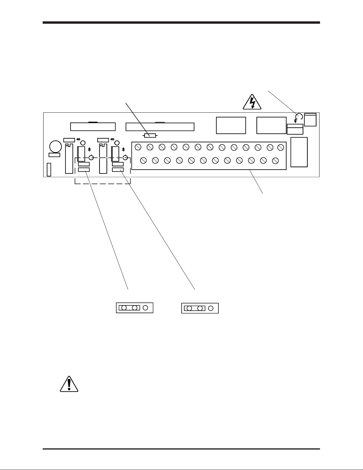
Terminal Board
The terminal printed wiring board is shown in the detail below. See Terminal Connections and
Functions starting on page 5-3. This board is used in all drive sizes.
Fused Resistor for P24
Charge LED
P24 RES RR F R S1 S2 S3 S4
ST FM AM CC CC RX PP IV FP FLC FLB FLA
0-1mA 4-20 mA 0-1mA
JP3
JP4
4-20 mA
RCHARCHCLOWALOW
C
Terminal Block
Jumper JP3 is used to set AM terminal and
Jumper JP4 is used to set FM terminal.
CAUTION
Turn off power to the drive before connecting or
disconnecting any wiring to the terminal block.
5 - 1
Page 27
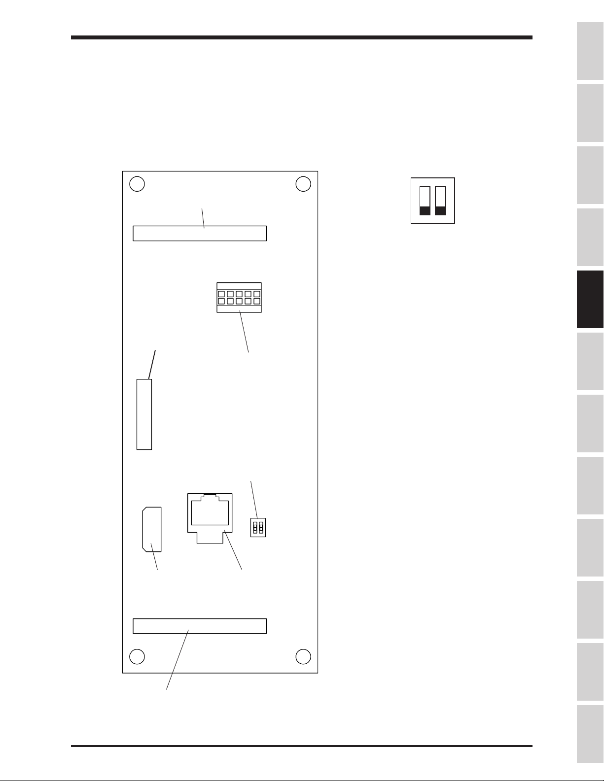
Control Board
The control printed wiring board is shown in the detail below. This control board is used in
all drive sizes.
Option board
connector
(40-pin)
Ribbon cable
connector
(back side)
Operation
panel
connector
TOSHIBA
I5
Dip Switch SW1
(Detail)
10V
When a 4(0)-20mA reference signal is input
to terminal "IV", set switch SW1 to I
When a 0-10 volt reference signal is input to
terminal "IV", set SW1 to V
When a +/- 0-5 volt reference signal is input
to terminal "RX", set SW1 to 5
When a +/- 0-10 volt reference signal is
input to terminal "RX", set SW1 to 10
Precautions
Specifications
Wiring
JumpersPanelKeypadParametersProgrammingServiceDimensionsIndex Inspection
Option
ROM
socket
Ribbon cable
connector
Dip Switch
SW1
(see detail 1
this page)
RS-232
Communication
connector
Make connections to this board only with power off.
5 - 2
Page 28
TOSHIBA
Terminal Connections and Functions
Terminal Terminal functions Terminal
name location
L1, L2, L3 Line input supply terminals for models H3-2035 to H3-2330:
(R, S, T) Connect to either 3ø, 50Hz, 200VAC or 3ø, 60Hz, 200 to 230VAC.
Line input supply terminals for models H3-4055 to H3-420K:
Connect to either 3ø, 50HZ, 400VAC or 3ø, 60Hz, 400 to 460VAC.
Drives can be operated on single phase power with when
appropriately derated; contact Toshiba distributor for information.
T1, T2, T3 Motor output terminals. Connect these terminals to a 3-phase
(U, V, W) induction motor of the proper voltage, current, and horsepower.
PA, PB Braking resistor output terminals. Connect to an external dynamic
braking resistor (available only on 30 HP and smaller drives).
FLA, FLB, FLC Programmable relay contact output. The contact rating is
250VAC - 2A. Default setting closes FLA-FLC and opens FLB-FLC
when protective function has been activated.
Terminal
block
or
bus bar
P24 Unregulated 24Vdc power supply (24Vdc, 50mA maximum). P24 is
protected by fused resistor found on the terminal board (see p. 5-1).
RCH(A & C) Programmable relay contact output. Standard setting closes
contact when an acc/dec is complete, or when the output
frequency is within a specified range. Contact rating is 250Vac - 2A.
LOW(A & C) Programmable relay contact output. Standard setting closes
contact when a preset low speed or a preset lower limit is
reached. Contact rating is 250Vac - 2A.
PP 10 VDC supply typically used to drive potentiometers. Wipers from
pots typically connected to "RR" or "RX" terminals.
FM* Programmable analog output. Outputs 0 - 1mA or 4 - 20mA (set by
JP4 on terminal board (see section 5.1)). This terminal can
be connected to an external analog meter. Use either an ammeter
rated 1mA DC/20 mA DC at full scale or a voltmeter rated 7.5Vdc at
full scale (true analog output). See page 9-23 for programming.
AM* Programmable analog output. Outputs 0 - 1mA or 4 - 20mA (set by
JP3 on terminal board (see section 5.1)). This terminal can
be connected to an external analog meter. Use either an ammeter
rated 1mA DC/20 mA DC at full scale or a voltmeter rated 7.5Vdc at
full scale (true analog output). See page 9-23 for programming.
Terminal
block
(See page
5-1)
FP Dedicated open-collector output. Pulses that are 48, 96, or
360-times the output frequency are available according to the
parameter settings (must connect external supply through pull-up
resistor to measure output).
* Do not make/break connections to these terminals with the drive powered.
5 - 3
Page 29
TOSHIBA
Terminal Connections and Functions (cont'd)
Terminal Terminal functions Terminal
name location
CC This is the common return for all of the input and output terminals.
(2-terminals) Do not connect this terminal to ground.
RR Programmable analog input. Default setting allows user to
input a 0 - 10VDC signal as a frequency command. Input has
bias/gain adjustments.
IV Programmable analog input. User can input a 0 - 10VDC signal or a
4 - 20 mA DC signal as a frequency command (selection of current
or voltage done via dipswitch on control board (see page 5-2).
Input has bias gain adjustments.
RX Programmable analog input. User can input a +/- 10VDC or a
+/- 5VDC signal as a frequency command (see page 5-2). Input
has bias/gain adjustments for forward and reverse operation.
ST Programmable digital input. With default setting, shorting terminal
to "CC" enables drive. Opening "ST" to "CC" coasts motor.
F Programmable digital input. With default setting, shorting terminal
to "CC" gives drive forward run command. Opening "F" to "CC"
decels motor to a stop.
R Programmable digital input. With default setting, shorting terminal
to "CC" gives drive reverse run command. Opening "R" to "CC"
decels motor to a stop.
Do not connect to GND(E).
Terminal
block
(See page
5-1)
Precautions
Specifications
Wiring
JumpersPanelKeypadParametersProgrammingServiceDimensionsIndex Inspection
S1 Programmable digital input. With default setting, shorting "S1" to
"CC" gives drive preset speed frequency reference.
S2 Programmable digital input. With default setting, shorting "S3" to
"CC" gives drive preset speed frequency reference.
S3 Programmable digital input. With default setting, shorting "S2" to
"CC" gives drive preset speed frequency reference.
S4 Programmable digital input. With default setting, shorting "S4" to
"CC" gives drive preset speed frequency reference.
RES Programmable digital input. With default setting, shorting "RES" to
"CC" resets a tripped drive.
5 - 4
Page 30
SECTION 6: Operating Panel
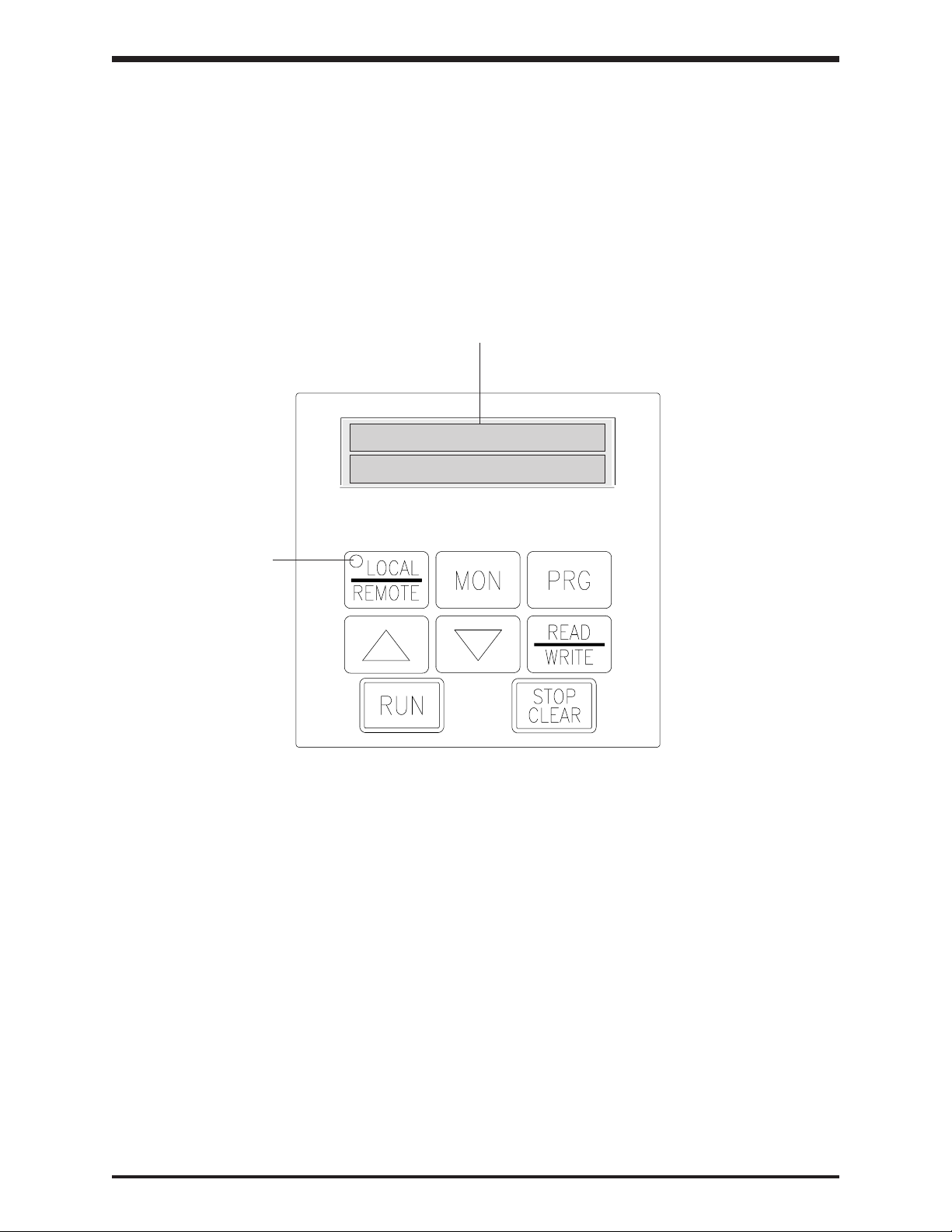
Operating Panel Layout
The operating panel enables the user to enable or disable the keypad, input commands
from the keypad, and monitor the H3's operation on the liquid crystal display. The panel
consists of the keypad, 20 character x 2-line LCD and a LED in the LOCAL/REMOTE
button of the keypad. The illustration below shows the operating panel keypad layout and
the locations of the keys and display.
TOSHIBA
Liquid crystal display
Local / remote
LED
6 - 1
Page 31

Operating Panel Keys and Functions
The following chart explains each of the key functions on the keypad
Key
Up scroll key used for incrementing numerical values. Also, when a parameter or
group name is displayed, the name of the previous parameter/group can be
displayed by pressing this key.
TOSHIBA
Keys and Functions
Function
Precautions
RUN
LOCAL
REMOTE
STOP
CLEAR
MON
Down scroll key used for decrementing numerical values. Also, when a
parameter or group name is displayed, the name of the next parameter/group
can be displayed by pressing this key.
Used to start a run from the keypad (local control).
Key changes between the local control mode and the terminal block input
control mode operation. When the local control LED in the keypad is "on",
operation of the drive is from the keypad.
This key functions as the STOP key when running from keypad (local control). In
all other modes, emergency off is engaged when this key is pressed twice.
During a drive trip, the tripped state can be reset by pressing this key twice.
This key is used to enter the monitor mode..
Specifications
Wiring
JumpersPanelKeypadParametersProgrammingServiceDimensionsIndex Inspection
READ
WRITE
PRG
This key is used to select or enter a parameter name, a parameter value, a
frequency command, or a group name.
This key is used to enter the programming mode.
6 - 2
Page 32

TOSHIBA
SECTION 7: Keypad Operating Functions
This chapter discusses basic keypad operating functions. The keypad allows the user to enter one of four
modes: LOCAL, REMOTE, PROGRAMMING, or MONITORING.
LOCAL MODE
Turn on the power source (MCCB). The drive will display OUTPUT FREQUENCY 0.0Hz.
Press the LOCAL/REMOTE button so that the local/remote LED is on. The illuminated LED
indicates that the drive is receiving run/stop commands from the keypad (LOCAL mode).
Set the operating frequency pressing the 'up arrow' or 'down arrow' keys. Notice that display
changes to FREQUENCY COMMAND.
Press READ/WRITE to save frequency. Display changes back to OUTPUT FREQUENCY.
When the RUN key is pressed, the drive will output a frequency that will increase according to
the set acceleration time. The panel control LED will blink to indicate motor is running.
When the STOP/CLEAR key is pressed, the drive outputs a frequency that will decrease
according to the set deceleration time. The motor will decelerate and stop.
If the power switch is turned off while the drive is running a motor, the motor will coast to a stop.
This method should be used for emergency stopping only.
Avoid frequent starting and stopping of the H3 by
CAUTION
The output frequency can be changed while running by pressing
When one of these keys is pressed the LCD display will blink, indicating that the value is being
changed. When the desired frequency is shown on the display, press the READ/WRITE key. The
output frequency will change even if the READ/WRITE key is not pressed. However, if power is
removed and the READ/WRITE key has not been pressed then the 'new' frequency will be lost
because it was not written into the EEPROM.
LOCAL MODE: FORWARD/REVERSE CHANGE
In LOCAL mode, motor direction can be changed on the fly from the keypad if Item 25,
DIRECTION SELECTION (FORWARD/REV)is set to "1" (its default):
Press READ/WRITE and
briefly display MOTOR RUN DIRECTION: FORWARD).
Pressing READ/WRITE and
(drive will briefly display MOTOR RUN DIRECTION: REVERSE).
Reverse runs can be disabled via Item 5, REVERSE OPERATION DISABLE (see page 8-1).
turning the (MCCB) power on and off. This will shorten
the life of the drive.
up arrow
at the same time to forward direction command ( drive will
down arrow
up arrow
at the same time results in a reverse direction command
or
down arrow
key.
LOCAL MODE: JOG
To jog from the keypad, program Item 108, JOG RUN FREQUENCY and Item 109, JOG STOP
METHOD as desired (see page 8-9).
In LOCAL mode and with display of OUTPUT FREQUENCY, press PRG twice. Drive displays
FORWARD JOG MODE (PRESS RUN). Direction can be changed with up/down arrows.
Pressing RUN starts jog. Releasing RUN stops jog according to Item 109, JOG STOP METHOD.
7 - 1
Page 33

TOSHIBA
LOCAL MODE: COAST STOP
In LOCAL mode, the drive's stop method can be changed to let the motor coast with the following
keystrokes.
Keystroke Display Comment
OUTPUT FREQUENCY Standard output frequency display
60.0 HZ
LOCAL/REMOTE COAST STOP COMMAND Drive prompts user for coast stop command
(PRESS STOP)
STOP/CLEAR OUTPUT FREQUENCY Drive immediately stops firing transistors and motor
0.0 HZ coasts to a stop
Precautions
Specifications
PROGRAMMING MODE
Pressing the PRG button allows users to enter the programming mode. See parameter tree on
page 8-33 and parameter charts starting on page 8-1. Parameter explanations and examples can
be found in section 9.
REMOTE MODE
The drive operates in REMOTE mode when the LOCAL/REMOTE LED is not illuminated. The
LOCAL/REMOTE LED can be turned on and off with the LOCAL/REMOTE key only when the
drive is stopped and at 0.0 Hz. With default programming, the drive powers up in remote mode. In
the remote mode, the drive is stopped/started remotely (e.g. from the terminal strip). To initiate a
run, the drive must have:
1. Drive enable ( e.g. "ST"-"CC" made)
2. Frequency command ( e.g. analog input to "IV", "RR", or other termials)
3. Direction command ( e.g. "R"-"CC" closure or "F"-"CC" closure )
See pages 5-2 and 4-1 for information on physical connections to the drive. See Items 44-55
on page 8-5 for information on the functions available using the input terminals. See Item 281,
COMMAND MODE SELECTION and Item 282, FREQUENCY MODE SELECTION for information on
how to set where the drive receives start/stop and frequency commands.
REMOTE MODE: EMERGENCY OFF
EMERGENCY OFF can be executed from the keypad when running and operating in remote
mode. EMERGENCY OFF is stored as a past fault in the monitor, but does not change the state
of any "fault" contacts. When running in remote mode, press STOP/CLEAR twice to initiate an
EMERGENCY OFF command. Drive will stop motor according to method selected in Item 151,
EMERGENCY OFF MODE SELECTION.
Wiring
JumpersPanelKeypadParametersProgrammingServiceDimensionsIndex Inspection
OTHER KEYPAD FUNCTIONS: LANGUAGE SELECTION
To change languages, press LOCAL/REMOTE + MON + PRG together with the display
showing OUTPUT FREQUENCY. Use the arrows to select the desired language and press WRT
to enter. As of 8/97, English and German are supported. German is available on the version 121
keypad ROM. To check keypad ROM number, press and hold the PRG button after pressing the
three buttons together as mentioned above. If drive displays "79", the keypad ROM is version 121;
if the drive displays "6E", the keypad ROM version is 110. If the drive does nothing, keypad ROM
is version 100.
7 - 2
Page 34

MONITOR MODE
Pressing the MON key switches the drive to monitor mode. The following table is an example of
the drive operation variables visible in the monitor:
Keystroke Display Explanation
MON MOTOR RUN DIRECTION: Pressing the MON key places drive in monitor
down arrow
down arrow
down arrow
down arrow
down arrow
down arrow
down arrow
down arrow
down arrow
down arrow
down arrow
down arrow
down arrow
TOSHIBA
OUTPUT FREQUENCY Standard output frequency display
0.0Hz
FORWARD mode. The first monitor window indicates direction.
MONITOR #1 Programmable monitor #1
0.0 Hz (the default shows frequency command)
LOAD CURRENT Programmable monitor #2
0% (default setting shows total current in percent)
INPUT VOLTAGE Programmable monitor #3
228V (default setting shows input voltage)
OUTPUT VOLTAGE Programmable monitor #4
0V (default setting shows output voltage)
STATUS: R:-- S1:ON Input terminal monitor. Drive displays "ON"
S2:-- S3:ON S4:-- when terminal is shorted to "CC".
ST:ON F:-- RES:ON Input terminal monitor. Drive displays "ON"
S5:-- S6:ON S7:-- when terminal is shorted to "CC".
RCH:ON LOW:ON FL:ON Output contact monitor. Drive displays "ON" when
OUT:ON FAN:-- MC:ON output is energized.
CUMULATIVE RUN TIME Non-resettable run time monitor. ".01" = 1 hour.
0.00
PAST TRIP #1 Past trip #1 monitor
OVERCURRENT (ACCEL)
PAST TRIP #2 Past trip #2 monitor
OVERCURRENT (DECEL)
PAST TRIP #3 Past trip #3 monitor
OVERVOLTAGE (DECEL)
PAST TRIP #4 Past trip #4 monitor
NO ERROR
MOTOR RUN DIRECTION: Return to the first monitor window
FORWARD
The monitor has no effect on what is happening to the motor and contains information useful for
start-ups and troubleshooting. If the down/up arrow key is pressed continuously, every 0.5
seconds the next/previous item will be displayed.
As illustrated above, the monitor displays MONITOR #1, LOAD CURRENT, INPUT VOLTAGE,
and OUTPUT VOLTAGE as default. The four variables displayed in these monitor windows are
programmable via Items 289-292 (see page 8-30).
Terminals "S6", "S7", and "S8" exist on option boards INV3-COM-B and INV3-COM-D. Terminal
"OUT" is an output contact available on option boards INV3-COM-B and INV3-COM-D. "MC" is
the soft start resistor bypass contactor (should always show "ON").
Monitor currents can be shown in amps by adjusting Item 296, CURRENT UNITS SELECTION to
"1". Monitor voltages can be shown in percent by adjusting Item 297, VOLTAGE UNITS
SELECTION to "0".
The monitor's past four faults can be cleared by setting Item 280, STANDARD SETTING MODE
SELECTION to "4".
7 - 3
Page 35
TOSHIBA
MONITORING "RR" INPUT SPECIAL FUNCTION
The "RR" terminal can be used to adjust the following drive parameters on the fly: Maximum
Output Frequency, accel/decel times, voltage boost, and stall level. When Item 289, 290, 291, or
292 are programmed to "14", one of the drive's monitor windows will display the following:
Setting of Item 79, RR INPUT
SPECIAL FUNCTION SELECT Monitor display
1 With 10 volts on the "RR" terminal, this monitor shows MAXIMUM
OUTPUT FREQUENCY. Zero volts on "RR" makes the effective
Maximum Output Frequency 30 Hz. See Item 1, MAXIMUM OUTPUT
FREQUENCY.
2 This monitor displays the acc/dec multiplier. Zero volts on "RR" results
in a display of "1.0". Ten volts on "RR" results in a display of "10.0".
3 This monitor displays the effective voltage boost. Zero volts on the
"RR" terminal results in a "0.0" display. At ten volts, VOLTAGE
BOOST is displayed.
4 This monitor shows effective Stall Protection Current Level. If Item 296,
CURRENT UNITS SELECTION is set to "1", no units will be
displayed with the current value.
MONITORING DURING PATTERN RUN
During a pattern run, the following four windows are added to the monitor sequence:
Precautions
Specifications
Wiring
JumpersPanelKeypadParametersProgrammingServiceDimensionsIndex Inspection
Key Operation LCD Message Explanation
OUTPUT FREQUENCY Standard output frequency display
30.0HZ
MON PATTERN GROUP #1 Indicates the active pattern group number
SPEED #3 and current speed used.
down arrow NUMBER OF CYCLES Indicates how many pattern group repetitions
REMAINING 145 are remaining
down arrow PRESET SPEED # 12 Indicates the preset speed currently used.
down arrow REMAINING PATTERN Indicates the remaining pattern time
TIME 2365 MIN
down arrow MOTOR RUN DIRECTION: Beginning of regular monitor windows.
FORWARD
7 - 4
Page 36
TOSHIBA
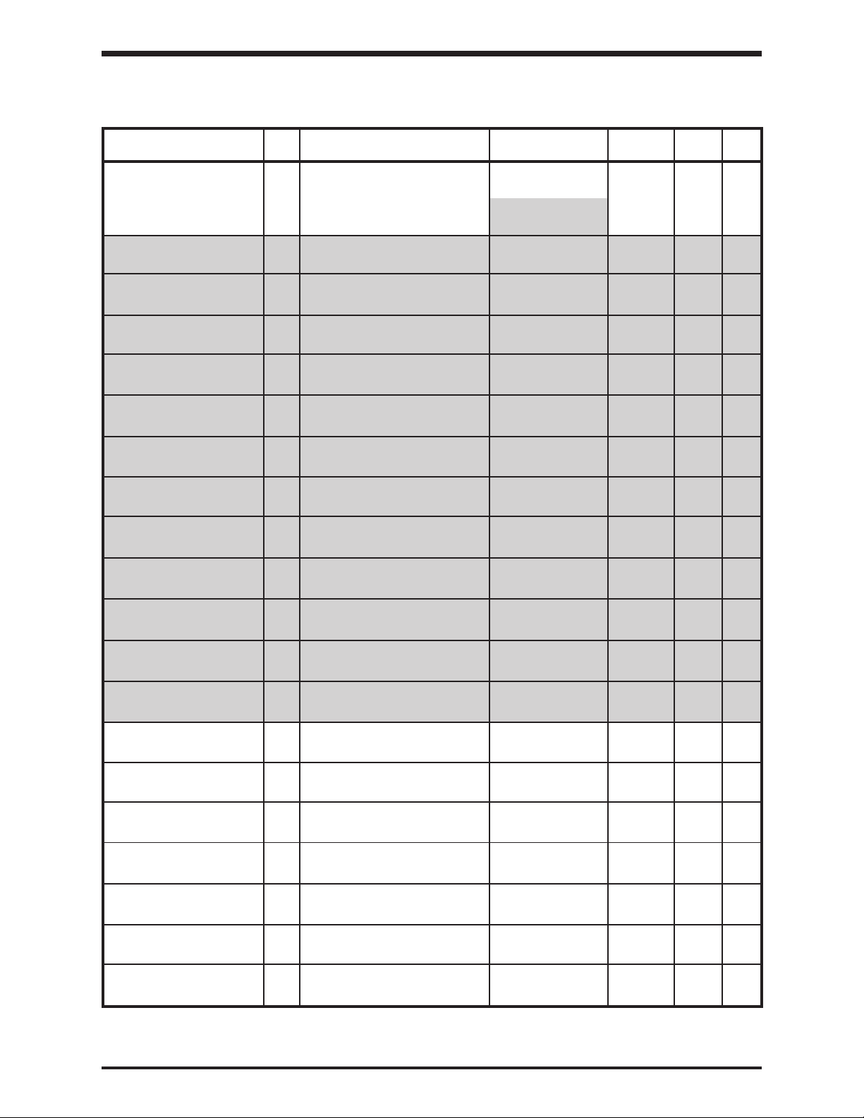
SECTION 8: Programming Charts
GROUP:FUNDAMENTAL PARAMETERS #1
LIQUID CRYSTAL DISPLAY ADJUSTMENT
MAXIMUM OUTPUT 1 Maximum frequency 30 - 400 Hz 0.01/0.1 Hz 80 Hz 9-3
FREQUENCY
BASE FREQUENCY #1 2 Base frequency #1 25 - 400 Hz 0.01/0.1 Hz 60 Hz 9-3
BASE FREQUENCY 3 Base frequency voltage selection 0: Input voltage level - 1 9-3
VOLTAGE SELECT 1: Automatic setting
MAXIMUM OUTPUT 4 Maximum voltage #1 for 230V 0 - 255V 1V 230V 9-3
VOLTAGE #1 Maximum voltage #1 for 460V 0 - 510V 1V 460V 9-3
REVERSE OPERATION 5 Reverse operation disable selection 0: Reverse allowed - 0 9-3
DISABLE SELECT 1: Reverse not
UPPER LIMIT 6 Upper limit frequency 0.0 Hz - Maximum 0.01/0.1 Hz 80.0 9-3
FREQUENCY Output Frequency
LOWER LIMIT 7 Lower limit frequency 0.0 Hz - Upper 0.01/0.1 Hz 0.0 9-3
FREQUENCY Limit Frequency
ITEM
NO.
PARAMETER
DESCRIPTION
RANGE
2: Stationary setting
allowed
DISPLAY
RESOLUTION
FACTORY
SETTING
PAGE
NO.
VOLTS PER HERTZ 8 V/F pattern 1: Constant torque * - 1 9-3
PATTERN 2: Variable torque *
VOLTAGE BOOST #1 9 * 30 HP and less 0 - 30% 0.1% 3% 9-4
40 HP and greater 1%
ACCELERATION TIME #1 10 60 HP and less 0.1-6000/0.01-600.0 0.1s/0.01s 10 sec 9-4
75 HP and greater 60 sec
DECELERATION TIME #1 11 60 HP and less 0.1-6000/0.01-600.0 0.1s/0.01s 10 sec 9-4
75 HP and greater 60 sec
ACC/DEC PATTERN #1 12 Acc/Dec pattern #1 0: Linear - 0 9-4
SELECTION 1: Self-adjusting
ACCEL/DECEL PATTERN 13 Acc/Dec pattern adjustment 0 - 50 1% 25 9-5
ADJUST LOW amounts (low)
ACCEL/DECEL PATTERN 14 Acc/Dec pattern adjustment 0 - 50 1% 25 9-5
ADJUST HIGH amounts (high)
3: Automatic torque
boost
4: Automatic torque
boost with
automatic energy
savings feature
5: Vector control
6: Vector control with
automatic energy
savings feature
2: S-Pattern
3: Overspeed Pattern
*Item 9 is available only when Item 8 Adjustment Range option 1 or 2 is selected.
8 - 1
Page 37
TOSHIBA
GROUP:FUNDAMENTAL PARAMETERS #2
LIQUID CRYSTAL DISPLAY ADJUSTMENT
BASE FREQUENCY #2 15 Base frequency #2 25 - 400 Hz 0.01/0.1 Hz 60.0 9-5
MAXIMUM OUTPUT 16 Maximum voltage #2 for 230V 0 - 255V 1V 230V 9-5
VOLTAGE #2 Maximum voltage #2 for 460V 0 - 510V 1V 460V 9-5
ITEM
NO.
PARAMETER
DESCRIPTION
RANGE
DISPLAY
RESOLUTION
FACTORY
SETTING
PAGE
NO.
Precautions
VOLTAGE BOOST #2 17 * 30 HP and less 0 - 30% 0.1% 3% 9-5
40 HP and greater 1%
ELECTRONIC THERMAL 18 Electronic thermal protection 10-100% or amps 1%/A 100 9-5
PROTECT LVL #2 level #2
STALL PROTECTION 19 turn stall #2 on/off 0: On ** - 0 9-5
SELECTION #2 1: Off
STALL PROTECTION 20** adjust stall current level #2 10-215% or amps 1%/A 120% 9-5
LEVEL #2
ACCELERATION TIME #2 21 60 HP and less 0.1-6000/0.01-600.0 0.1s/0.01s 10 sec 9-5
75 HP and greater 60 sec
DECELERATION TIME #2 22 60 HP and less 0.1-6000/0.01-600.0 0.1s/0.01s 10 sec 9-5
75 HP and greater 60 sec
ACC/DEC PATTERN #2 23 Acc/Dec pattern #2 0: Linear - 0 9-5
SELECTION 1: Self-adjusting
2: S-Pattern
3: Overspeed Pattern
ACC/DEC #1/#2 SWITCH 24 Hz at which to switch from 0 - Max. Output Freq. 0.1/0.01 Hz 0.0 9-5
FREQUENCY ACC1/DEC1 to ACC2/DEC2 (Item 1)
*Item 17 is available only when Item 8, VOLTS PER HERTZ PATTERN Adjustment Range option 1 or 2
is selected.
**Item 20 is available only when Item 19 Adjustment Range option 0 is selected.
Specifications
Wiring
JumpersPanelKeypadParametersProgrammingServiceDimensionsIndex Inspection
8 - 2
Page 38

TOSHIBA
GROUP:PANEL CONTROL PARAMETERS
LIQUID CRYSTAL DISPLAY ADJUSTMENT
DIRECTION SELECTION 25 Forward/reverse 0: Reverse - 1 9-5
(FORWARD/REV) 1: Forward
STOP PATTERN 26 Stop pattern selection 0: Decelerated stop - 0 9-5
SELECTION 1: Coast stop
FUNDAMENTAL PARAM 27 Fundamental parameter #1 or #2 1: Fundamental - 1 9-5
SWITCHING selection parameter #1
ACCEL/DECEL #1/#2 28 Acc/dec #1 or #2 1 : Acc/dec #1 - 1 9-6
SELECTION selection 2: Acc/dec #2
PANEL RESET 29 Panel reset selection 0: All possible - 0 9-6
SELECTION 1: Only OL can be
ITEM
NO.
PARAMETER
DESCRIPTION
RANGE
2: Fundamental
parameter #2
reset
2: Only OL, OC1,
OC2, OC3 can be
reset
DISPLAY
RESOLUTION
FACTORY
SETTING
PAGE
NO.
PANEL FEEDBACK 30 Panel feedback control 0: On (valid when - 0 9-6
CONTROL (PID, speed feedback, drooping) panel operation is
selected)
1: Off (invalid when
panel operation is
selected)
8 - 3
Page 39

TOSHIBA
GROUP:SPECIAL CONTROL PARAMETERS
LIQUID CRYSTAL DISPLAY ADJUSTMENT
START-UP FREQUENCY 31 Start-up frequency 0.0 - 10 0.1/0.01 Hz 0.1 9-6
END FREQUENCY 32 End frequency 0.0 - 30 0.1/0.01 Hz 0.1 9-6
RUN FREQUENCY 33 Run frequency 0.0 - max output freq 0.1/0.01 Hz 0.0 9-6
RUN FREQUENCY 34 Run frequency hysteresis 0.0 - 30 0.1/0.01 Hz 0.0 9-6
HYSTERESIS
ENABLE JUMP 35 Jump frequency enable 0: Function OFF - 0 9-6
FREQUENCIES 1: Function ON *
JUMP FREQUENCY #1 36* Jump frequency #1 0.0-Max Output Freq 0.1/0.01 Hz 0.0 9-6
JUMP FREQUENCY #1 37* +/- band # 1 0 - 30 0.1/0.01 Hz 0.0 9-7
BANDWIDTH
JUMP FREQUENCY #2 38* Jump frequency #2 0.0-Max Output Freq 0.1/0.01 Hz 0.0 9-7
JUMP FREQUENCY #2 39* +/- band # 2 0 - 30 0.1/0.01 Hz 0.0 9-7
BANDWIDTH
JUMP FREQUENCY #3 40* Jump frequency #3 0.0-Max Output Freq 0.1/0.01 Hz 0.0 9-7
ITEM
NO.
PARAMETER
DESCRIPTION
RANGE
DISPLAY
RESOLUTION
FACTORY
SETTING
PAGE
NO.
Precautions
Specifications
Wiring
JumpersPanelKeypadParametersProgrammingServiceDimensionsIndex Inspection
JUMP FREQUENCY #3 41* +/- band # 3 0 - 30 0.1/0.01 Hz 0.0 9-7
BANDWIDTH
PWM CARRIER 42 PWM carrier frequency for 230V 500 Hz - 10 kHz 0.1kHz 2.2 kHz 9-7
FREQUENCY (.75-30 HP)
PWM carrier frequency for 460V 500 Hz - 10 kHz
(1-125 HP)
PWM carrier frequency for 460V 500 Hz - 5 kHz
(125-300 HP)
*Items 36 - 41 are available only when Item 35 Adjustment Range option 1 is selected.
8 - 4
Page 40
TOSHIBA
GROUP:TERMINAL SELECTION PARAMETERS
LIQUID CRYSTAL DISPLAY ADJUSTMENT
INPUT TERMINAL 43 Input terminal selection 0: Standard terminal - 0 9-7
SELECTION functions
"R" INPUT TERMINAL 44* assign function to "R" terminal 0 - 54 - 0 9-7
FUNCTION (default function is reverse run) 5-1
"S1" INPUT TERMINAL 45* assign function to"S1" terminal 0 - 54 - 1 9-7
FUNCTION (default function is preset speed) 5-1
"S2" INPUT TERMINAL 46* assign function to "S2" terminal 0 - 54 - 2 9-7
FUNCTION (default function is preset speed) 5-1
"S3" INPUT TERMINAL 47* assign function to "S3" terminal 0 - 54 - 3 9-7
FUNCTION (default function is preset speed) 5-1
"S4" INPUT TERMINAL 48* assign function to "S4" terminal 0 - 54 - 4 9-7
FUNCTION (default function is preset speed) 5-1
"F" INPUT TERMINAL 49* assign function to "F" terminal 0 - 54 - 5 9-7
FUNCTION (default function is forward run) 5-1
ITEM
NO.
PARAMETER
DESCRIPTION
RANGE
1: custom terminal
functions *
DISPLAY
RESOLUTION
FACTORY
SETTING
PAGE
NO.
"RES" INPUT TERMINAL 50* assign function to "RES" terminal 0 - 54 - 6 9-8
FUNCTION (default function is fault reset) 5-1
"ST" INPUT TERMINAL 51* assign function to "ST" terminal 0 - 54 - 7 9-8
FUNCTION (default function is drive enable) 5-1
"S5" INPUT TERMINAL 52* assign function to "S5" terminal 0 - 54 - 8 9-8
FUNCTION (available on option board)
"S6" INPUT TERMINAL 53* assign function to "S6" terminal 0 - 54 - 9 9-8
FUNCTION (available on option board)
"S7" INPUT TERMINAL 54* assign function to "S7" terminal 0 - 54 - 10 9-8
FUNCTION (available on option board)
POTENTIAL TERMINAL 55* pick function that is always active 0 - 42 - 33 9-8
FUNCTION (no physical connection)
R, S1-S7 TERMINAL 56 "R" and "S1"-"S7" terminals' 1 - 100 1 6 9-10
RESPONSE TIME response time 5-1
"F" INPUT TERMINAL 57 "F" terminal response 1 - 100 1 6 9-10
RESPONSE TIME time selection 5-1
"RES" INPUT TERMINAL 58 "RES" terminal response 1 - 100 1 6 9-10
RESPONSE TIME time selection 5-1
"ST" INPUT TERMINAL 59 "ST" terminal response 1 - 100 1 6 9-10
RESPONSE TIME time selection 5-1
"RCH" CONTACTS 60 assign function to "RCH" 0 - 63 1 6 9-10
FUNCTION output contact 5-1
"RCH" CONTACTS 61 "RCH" output contact delay time 1 - 100 1 1 9-10
DELAY TIME 5-1
"RCH" CONTACTS 62 "RCH" output contact hold time 1 - 100 1 1 9-10
HOLD TIME 5-1
Table continued on next page
*Items 44 - 55 are available only when Item 43 Adjustment Range option 1 is selected.
8 - 5
Page 41
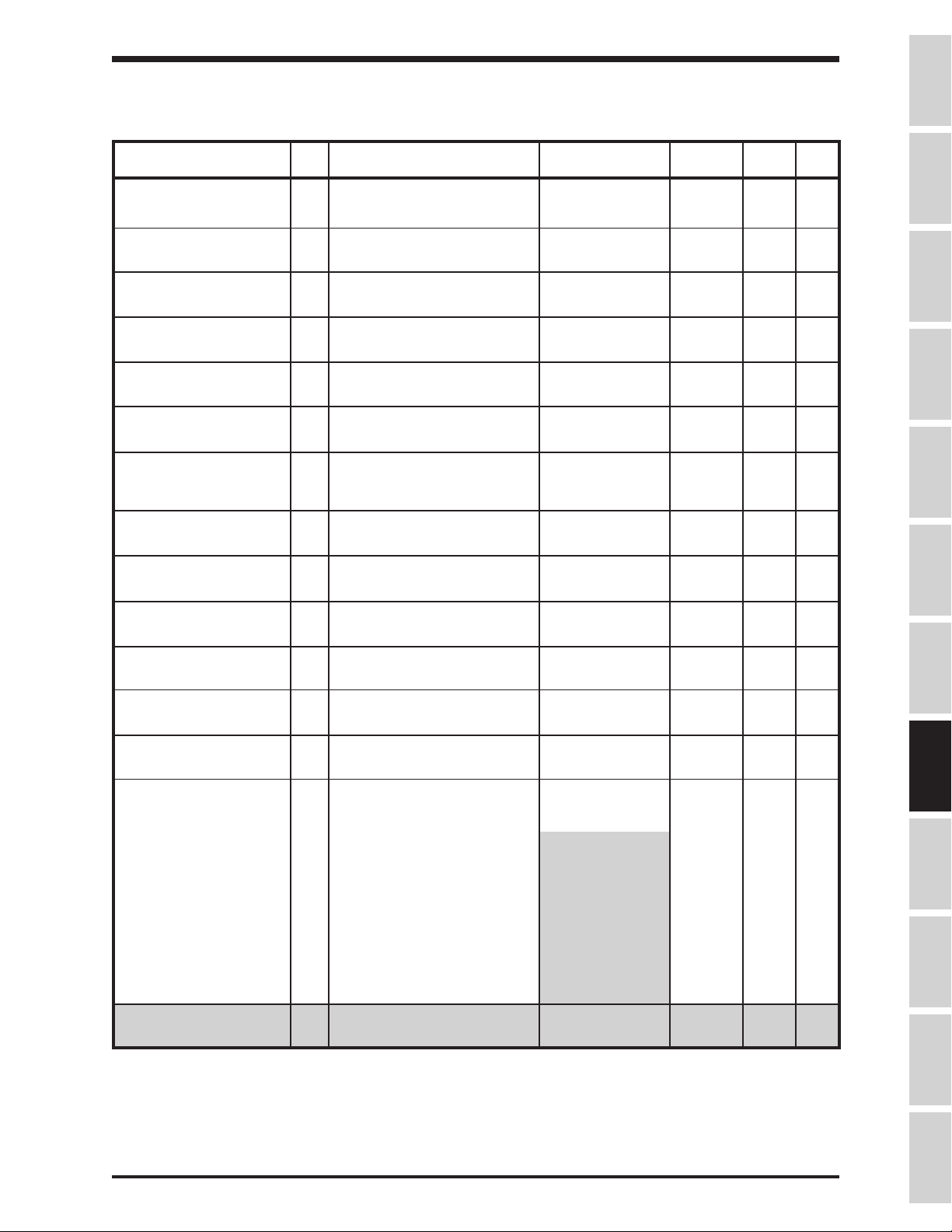
TOSHIBA
GROUP:TERMINAL SELECTION PARAMETERS (cont'd)
LIQUID CRYSTAL DISPLAY ADJUSTMENT
"LOW" CONTACTS 63 assign function to "LOW" 0 - 63 1 4 9-10
FUNCTION contact 5-1
"LOW" CONTACTS 64 "LOW" output contact 1 - 100 1 1 9-10
DELAY TIME delay time 5-1
"LOW" CONTACTS 65 "LOW" output contact 1 - 100 1 1 9-10
HOLD TIME hold time 5-1
"FL" CONTACTS 66 asssign function to "FL" output 0 - 63 1 10 9-10
FUNCTION contact 5-1
ITEM
NO.
PARAMETER
DESCRIPTION
RANGE
DISPLAY
RESOLUTION
FACTORY
SETTING
PAGE
NO.
Precautions
Specifications
"FL" CONTACTS 67 "FL" output contacts 1 - 100 1 1 9-10
DELAY TIME delay time 5-1
"FL" CONTACTS 68 "FL" output contacts 1 - 100 1 1 9-10
HOLD TIME hold time 5-1
"OUT" CONTACTS 69 assign function to "OUT" 0 - 61 1 8 9-10
FUNCTION output contacts
(available on option board)
"OUT" CONTACTS 70 "OUT" output contact delay time 1 - 100 1 1 9-10
DELAY TIME (available on option board)
"OUT" CONTACTS 71 "OUT" output contact hold time 1 - 100 1 1 9-10
HOLD TIME (available on option board)
LOW SPEED SIGNAL 72 Low-speed signal frequency 0 - Max. Output Freq. 0.1/0.01 Hz 0.0 9-13
OUTPUT FREQ
ACC/DEC COMPLETE 73 Acc/Dec complete detection 0 - Max. Output Freq. 0.1/0.01 Hz 2.5 9-13
DETECT BAND bandwidth
SPEED REACH MAXIMUM 74 Speed reach high frequency 0 - Max. Output Freq. 0.1/0.01 Hz 0.0 9-13
FREQUENCY
SPEED REACH MINIMUM 75 Speed reach low frequency 0 - Max. Output Freq. 0.1/0.01 Hz 0.0 9-13
FREQUENCY
COMMERCIAL POWER/INV 76 Bypass control 0: Off - 0 9-13
SWITCHING OUTPUT 1: Automatic
switching upon trip
2: Switching upon
receipt of
switching
signal *
3: Both 1 and 2
above*
Wiring
JumpersPanelKeypadParametersProgrammingServiceDimensionsIndex Inspection
COMMERCIAL POWER/INV 77* Incoming power/inverter 0 - Max Output Freq 0.1/0.01 Hz 60.0 Hz 9-13
SWITCH FREQ switching frequency
Table continued on next page
*Item 77 is available only when Item 76 Adjustment Range option 2 or 3 is selected.
8 - 6
Page 42

TOSHIBA
GROUP:TERMINAL SELECTION PARAMETERS (cont'd)
LIQUID CRYSTAL DISPLAY ADJUSTMENT
"FP" OUTPUT TERMINAL 78 Output terminal pulse 0: 48 times output frequency 0 9-13
PULSE FREQUENCY frequency selection 1: 96 times output frequency 5-1
RR INPUT SPECIAL 79 RR input special function selection 0: Standard 0 9-13
FUNCTION SELECT 1: Set effective Maximum 5-1
ITEM
NO.
PARAMETER
DESCRIPTION
RANGE
2: 360 times output frequency
Output Frequency
2: Scale ACC/DEC times
3: Set effective Voltage Boost
4: Set effective Stall Level
FACTORY
SETTING
PAGE
NO.
8 - 7
Page 43

TOSHIBA
GROUP:FREQUENCY SETTING PARAMETERS
LIQUID CRYSTAL DISPLAY ADJUSTMENT
FREQUENCY PRIORITY 80 Assign priority to frequency 1:RR terminal - 1 9-13
SELECTION #1 reference sources 2:IV terminal
FREQUENCY PRIORITY 81 Assign second priority 1:RR terminal 2 9-13
SELECTION #2 frequency reference source 2:IV terminal
ANALOG INPUT FILTER 82 Analog input filter 0 - 3 - 0 9-14
RR TERMINAL STANDARD 83 RR input selection 0 : Standard - 0 9-14
OR ADJUSTABLE 1: Adjustable * 5-1
RR REFERENCE SETTING 84* RR reference point #1 0 - 100% 1% 0 9-14
POINT #1 of terminal max (10V)
ITEM
NO.
PARAMETER
DESCRIPTION
RANGE
3:RX terminal
4:PG input
5:Binary input or MOP
3:RX terminal
4:PG input
5:Binary input or MOP
DISPLAY
RESOLUTION
FACTORY
SETTING
PAGE
NO.
Precautions
Specifications
Wiring
RR REF POINT #1 85* Output frequency desired 0 - Max. Out. Freq. 0.1/0.01 Hz 0.0 9-14
FREQUENCY with input entered in Item 84
RR REFERENCE SETTING 86* RR reference point #2 0 - 100% 1% 100 9-14
POINT #2 of terminal max (10V)
RR REF POINT #2 87* Output frequency desired 0 - Max.Out. Freq. 0.1/0.01 Hz 80.0 9-14
FREQUENCY with input entered in Item 86
IV TERMINAL STANDARD 88 IV input selection 0: Standard - 0 9-14
OR ADJUSTABLE 1: Adjustable ** 5-1
IV REFERENCE SETTING 89** IV reference point #1 0 - 100% 1% 20 9-14
POINT #1 of terminal maximum
IV REF POINT #1 90** Output frequency desired 0 - Max. Out. Freq. 0.1/0.01 Hz 0.0 9-14
FREQUENCY with input entered inItem 89
IV REFERENCE SETTING 91** IV reference point #2 0 - 100% 1% 100 9-14
POINT #2 of terminal maximum
IV REF POINT #2 92** Output frequency desired 0 - Max. Out. Freq. 0.1/0.01 Hz 80.0 9-14
FREQUENCY with input entered in Item 91
RX TERMINAL STANDARD 93 RX input selection 0: Standard - 0 9-14
OR ADJUSTABLE 1: Adjustable *** 5-1
RX REFERENCE SETTING 94*** RX reference point #1 -100 - 100% 1% 0 9-14
POINT #1 of terminal maximum
RX REF POINT #1 95*** Output Hz desired with input -Max. Out. Freq. to 0.1/0.01 Hz 0.0 9-14
FREQUENCY entered in Item 94 Max. Out. Freq.
JumpersPanelKeypadParametersProgrammingServiceDimensionsIndex Inspection
RX REFERENCE SETTING 96*** RX reference point #2 -100 - 100% 1% 100 9-14
POINT #2 of terminal maximum
RX REF POINT #2 97*** Output Hz desired with input -Max. Out. Freq. to 0.1/0.01 Hz 80.0 9-14
FREQUENCY entered in Item 96 Max. Out. Freq.
Table continued on next page
*Items 84 - 87 are available only when Item 83 Adjustment Range option 1 is selected.
**Items 89 - 92 are available only when Item 88 Adjustment Range option 1 is selected.
***Items 94 - 97 are available only when Item 93 Adjustment Range option 1 is selected.
8 - 8
Page 44
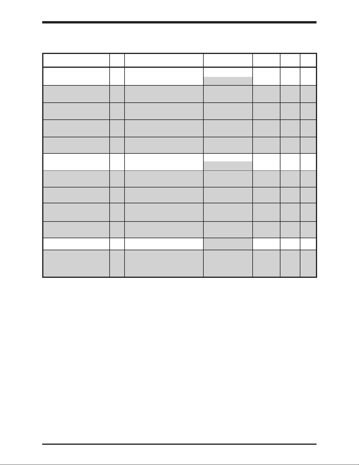
TOSHIBA
GROUP:FREQUENCY SETTING PARAMETERS (cont'd)
LIQUID CRYSTAL DISPLAY ADJUSTMENT
PG TERMINAL STANDARD 98 Bias/gain for PG input selection 0: Standard - 0 9-14
OR ADJUSTABLE (option board) 1 : Adjustable*
PG REFERENCE SETTING 99* PG reference point #1 -100 - 100% of Max. 1% 0 9-14
POINT #1 Out. Freq. X PPR
PG REF POINT #1 100* Output Hz desired when reference -Max. Out. Freq. to 0.1/0.01 Hz 0.0 9-14
FREQUENCY equals value entered in Item 99 Max. Out. Freq.
PG REFERENCE SETTING 101* PG reference point #2 -100 - 100% of Max. 1% 100 9-14
POINT #2 Out. Freq. X PPR
PG REF POINT #2 102* Output Hz desired when reference -Max. Out. Freq. to 0.1/0.01 Hz 80.0 9-14
FREQUENCY equals value entered in Item 101 Max. Out. Freq.
BINARY INPUT STD 103 Bias/gain for binary input 0: Standard - 0 9-14
OR ADJUSTABLE (via input terminals). 1: Adjustible**
BINARY REF SETTING 104** Binary reference point #1 0 - 100 % 1% 0 9-14
POINT #1
ITEM
NO.
PARAMETER
DESCRIPTION
RANGE
DISPLAY
RESOLUTION
FACTORY
SETTING
PAGE
NO.
BINARY REF POINT #1 105** Output Hz desired when reference -Max. Out. Freq. to 0.1/0.01 Hz 0.0 9-14
FREQUENCY equals value entered in Item 104 Max. Out. Freq.
BINARY REF SETTING 106** Binary reference point #2 0 - 100 % 1% 100 9-14
POINT #2
BINARY REF POINT #2 107** Output Hz desired when reference -Max. Out. Freq. to 0.1/0.01 Hz 80.0 9-14
FREQUENCY equals value entered in Item 106 Max. Out. Freq.
JOG RUN FREQUENCY 108 Jog run frequency 0.0 - 20*** 0.1/0.01 Hz 0.0 9-15
JOG STOP METHOD 109*** Jog stop control 0: Decelerated stop - 0 9-15
1: Coast to stop
2: DC injection
braking
Table continued on next page
*Items 99 - 102 are available only when Item 98 Adjustment Range option 1 is selected.
**Items 104 - 107 are available only when Item 103 Adjustment Range option 1 is selected.
***Item 109 is available only when Item 108 Adjustment Range is set to other than "0".
8 - 9
Page 45

TOSHIBA
GROUP:FREQUENCY SETTING PARAMETERS (cont'd)
LIQUID CRYSTAL DISPLAY ADJUSTMENT
PRESET SPEED 110 Selects number of preset speeds 0: Disabled - 0 9-15
SELECTION to be unblinded 1: 1st speed only *
PRESET SPEED MODE 111* Mode selection 0: Deactivated - 0 9-15
ACTIVATION 1: Activated
ITEM
NO.
PARAMETER
DESCRIPTION
RANGE
2: speeds 1 thru 2 *
3: speeds 1 thru 3*
4: speeds 1 thru 4*
5: speeds 1 thru 5*
6: speeds 1 thru 6*
7: speeds 1 thru 7*
8: speeds 1 thru 8*
9: speeds 1 thru 9*
10:speeds 1 thru 10*
11:speeds 1 thru 11*
12:speeds 1 thru 12*
13:speeds 1 thru 13*
14:speeds 1 thru 14*
15:speeds 1 thru 15*
DISPLAY
RESOLUTION
FACTORY
SETTING
PAGE
NO.
Precautions
Specifications
Wiring
PRESET SPEED #1 112* 1st speed Lower limit frequency 0.1/0.01 Hz 0.0 9-15
FREQUENCY to
PRESET SPEED #1 113* 1st speed run mode 0: Acc/dec #1, 0 9-15
OPERATING MODE forward run
PRESET SPEED #2 114* 2nd speed Lower limit frequency 0.1/0.01 Hz 0.0 9-15
FREQUENCY to
PRESET SPEED #2 115* 2nd speed run mode
OPERATING MODE
PRESET SPEED #3 116* 3rd speed Lower limit frequency 0.1/0.01 Hz 0.0 9-15
FREQUENCY to
upper limit frequency
1: Acc/dec #1,
reverse run
2: Acc/dec #2,
forward run
3: Acc/dec #2,
reverse run
4: Acc/dec #1,
forward run
5: Acc/dec #1,
reverse run
6: Acc/dec #2,
forward run
7: Acc/dec #2,
reverse run
upper limit frequency
Same options as
Item 113
upper limit frequency
- 0 9-15
JumpersPanelKeypadParametersProgrammingServiceDimensionsIndex Inspection
PRESET SPEED #3 117* 3rd speed run mode
OPERATING MODE
Same options as
Item 113
- 0 9-15
Table continued on next page
*Items 111 - 117 are available only when Item 110 Adjustment Range options 1 - 15 are selected.
8 - 10
Page 46

TOSHIBA
GROUP:FREQUENCY SETTING PARAMETERS (cont'd)
LIQUID CRYSTAL DISPLAY ADJUSTMENT
PRESET SPEED #4 118* 4th speed Lower limit frequency 0.1/0.01 Hz 0.0 9-15
FREQUENCY to
ITEM
NO.
PARAMETER
DESCRIPTION
RANGE
upper limit frequency
DISPLAY
RESOLUTION
FACTORY
SETTING
PAGE
NO.
PRESET SPEED #4 119* 4th speed run mode
OPERATING MODE
PRESET SPEED #5 120* 5th speed Lower limit frequency 0.1/0.01 Hz 0.0 9-15
FREQUENCY to
PRESET SPEED #5 121* 5th speed run mode
OPERATING MODE
PRESET SPEED #6 122* 6th speed Lower limit frequency 0.1/0.01 Hz 0.0 9-15
FREQUENCY to
PRESET SPEED #6 123* 6th speed run mode
OPERATING MODE
PRESET SPEED #7 124* 7th speed Lower limit frequency 0.1/0.01 Hz 0.0 9-15
FREQUENCY to
PRESET SPEED #7 125* 7th speed run mode
OPERATING MODE
PRESET SPEED #8 126* 8th speed Lower limit frequency 0.1/0.01 Hz 0.0 9-15
FREQUENCY to
PRESET SPEED #8 127* 8th speed run mode
OPERATING MODE
Same options as
Item 113
upper limit frequency
Same options as
Item 113
upper limit frequency
Same options as
Item 113
upper limit frequency
Same options as
Item 113
upper limit frequency
Same options as
Item 113
- 0 9-15
- 0 9-15
- 0 9-15
- 0 9-15
- 0 9-15
PRESET SPEED #9 128* 9th speed Lower limit frequency 0.1/0.01 Hz 0.0 9-15
FREQUENCY to
PRESET SPEED #9 129* 9th speed run mode
OPERATING MODE
PRESET SPEED #10 130* 10th speed Lower limit frequency 0.1/0.01 Hz 0.0 9-15
FREQUENCY to
PRESET SPEED #10 131* 10th speed run mode
OPERATING MODE
PRESET SPEED #11 132* 11th speed Lower limit frequency 0.1/0.01 Hz 0.0 9-15
FREQUENCY to
PRESET SPEED #11 133* 11th speed run mode
OPERATING MODE
upper limit frequency
Same options as
Item 113
upper limit frequency
Same options as
Item 113
upper limit frequency
Same options as
Item 113
- 0 9-15
- 0 9-15
- 0 9-15
Table continued on next page
*Items 118 - 133 are available only when Item 110 Adjustment Range options 1 - 15 are selected.
8 - 11
Page 47

TOSHIBA
GROUP:FREQUENCY SETTING PARAMETERS (cont'd)
LIQUID CRYSTAL DISPLAY ADJUSTMENT
PRESET SPEED #12 134* 12th speed Lower limit frequency 0.1/0.01 Hz 0.0 9-15
FREQUENCY to
PRESET SPEED #12 135* 12th speed run mode Same options as - 0 9-15
OPERATING MODE
PRESET SPEED #13 136* 13th speed Lower limit frequency 0.1/0.01 Hz 0.0 9-15
FREQUENCY to
ITEM
NO.
PARAMETER
DESCRIPTION
RANGE
upper limit frequency
Item 113
upper limit frequency
DISPLAY
RESOLUTION
FACTORY
SETTING
PAGE
NO.
Precautions
Specifications
PRESET SPEED #13 137* 13th speed run mode
OPERATING MODE
PRESET SPEED #14 138* 14th speed Lower limit frequency 0.1/0.01 Hz 0.0 9-15
FREQUENCY to
PRESET SPEED #14 139* 14th speed run mode
OPERATING MODE
PRESET SPEED #15 140* 15th speed Lower limit frequency 0.1/0.01 Hz 0.0 9-15
FREQUENCY to
PRESET SPEED #15 141* 15th speed run mode
OPERATING MODE
Same options as
Item 113
upper limit frequency
Same options as
Item 113
upper limit frequency
Same options as
Item 113
- 0 9-15
- 0 9-15
- 0 9-15
*Items 134 - 141 are available only when Item 110 Adjustment Range options 1 - 15 are selected.
Wiring
JumpersPanelKeypadParametersProgrammingServiceDimensionsIndex Inspection
8 - 12
Page 48
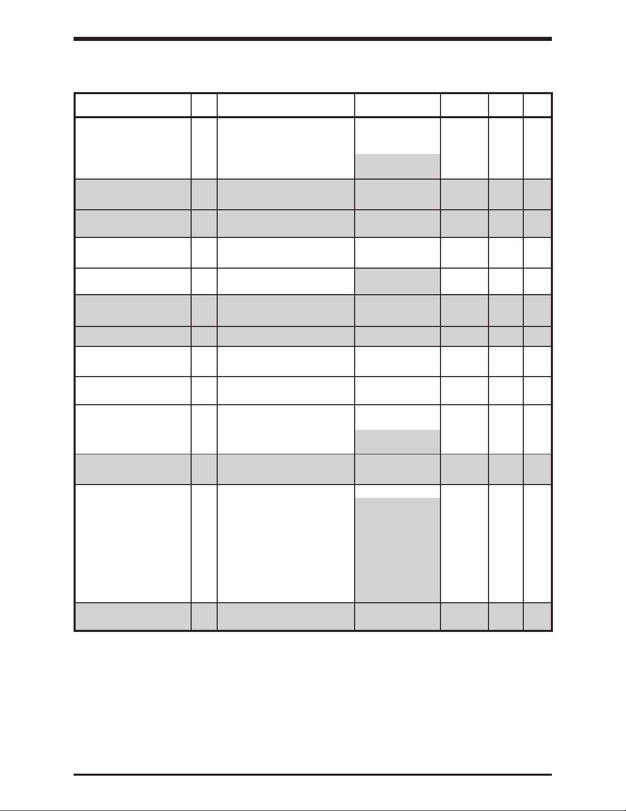
TOSHIBA
GROUP:PROTECTION PARAMETERS
LIQUID CRYSTAL DISPLAY ADJUSTMENT
DYNAMIC BRAKING 142 Dynamic braking selection 0: No DBR used - 0 9-15
SELECTION 1: DBR used. Drive's
BRAKING RESISTOR 143* DBR resistor value 1.0 - 1000 0.1 ohm ***** 9-15
VALUE
BRAKING RESISTOR 144* DBR capacity 0.01 - 600 0.01 kW ***** 9-15
POWER RATING
OVERVOLTAGE STALL 145 Overvoltage stall protection 0: On - 0 9-16
PROTECTION 1: Off
DC INJECTION START 146 DC injection starting frequency 0 - 120 ** 0.1/0.01 Hz 0.0 9-17
FREQUENCY
DC INJECTION CURRENT 147** DC injection current 0 - 100% or amps 1 %/A 0 9-17
MAGNITUDE
ITEM
NO.
PARAMETER
DESCRIPTION
RANGE
DBR OL protect off.
2: DBR used. Drive's
DBR OL protect on.
DISPLAY
RESOLUTION
FACTORY
SETTING
PAGE
NO.
DC INJECTION TIME 148** DC injection time 0 - 10 0.1 sec 0.0 9-17
FWD/REV DC INJECTION 149 DC injection during 0: Off - 0 9-17
PRIORITY CTRL direction change 1: On
MOTOR SHAFT 150 continuous DC trickle 0: O ff - 0 9-17
STATIONARY CTRL 1: On
EMERGENCY OFF MODE 151 Emergency stop selection 0: Coast to stop - 0 9-17
SELECTION 1: Decelerated stop
EMERGENCY OFF DC 152*** Emergency stop DC injection time 0 - 10 0.1 sec 0.1 9-17
INJECTION TIME
NUMBER OF RETRY 153 Retry selection 0: No retry - 0 9-17
ATTEMPTS 1: Retry 1 time ****
TIME BETWEEN RETRY 154 Retry time setting 0.0 - 10 0.1 sec 1.0 9-17
ATTEMPTS ****
2: DC injection
stop ***
2: Retry 2 times ****
3: Retry 3 times ****
4: Retry 4 times ****
5: Retry 5 times ****
6: Retry 6 times ****
7: Retry 7 times ****
8: Retry 8 times ****
9: Retry 9 times ****
10:Retry 10 times ****
Table continued on next page
*Items 143 - 144 are available only when Item 142 Adjustment Range option 2 is selected.
** Items 147 - 148 are available only when Item 146 Adjustment Range is set to other than "0".
*** Item 152 is available only when Item 151 Adjustment Range option 2 is selected.
**** Item 154 is available only when Item 153 Adjustment Range options 1 - 10 are selected.
***** Default wattage and ohm values depend on the inverter size.
8 - 13
Page 49
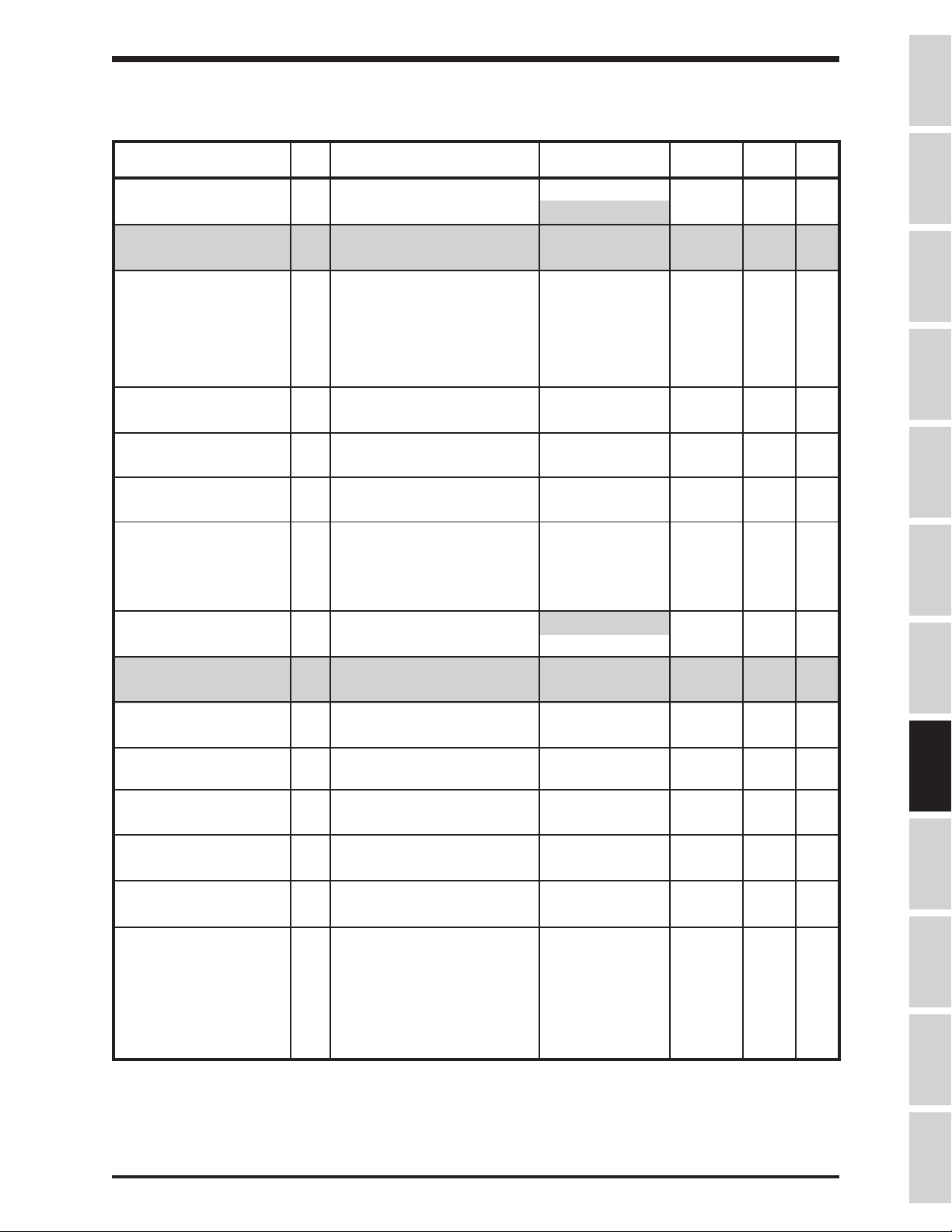
TOSHIBA
GROUP:PROTECTION PARAMETERS (cont'd)
LIQUID CRYSTAL DISPLAY ADJUSTMENT
REGENERATION POWER 155 allows drive to use regen 0: Off - 0 9-17
RIDE-THROUGH for control power 1: On *
REGENERATION RIDE- 156* maximum allowable 0.0 - 25 0.1 sec 2.0 9-17
THROUGH TIME ride-through time
AUTO-RESTART (MOTOR 157 "catch" a spinning motor 0: Off - 0 9-17
SPEED SEARCH) (forward or reverse) 1 : After momentary
ELECTRONIC THERMAL 158 sets drive's overload to 10-100% or amps 1%/A 100 9-18
PROTECT LVL 1 protect motor
OVERLOAD REDUCTION 159 frequency at which drive's motor 0 - 30 0.1/0.01 Hz 30.0 9-18
START FREQ overload becomes speed sensitive
ITEM
NO.
PARAMETER
DESCRIPTION
RANGE
power failure
(ride-through)
2: After "ST" is
shorted to "CC"
3: Both 1 and 2
DISPLAY
RESOLUTION
FACTORY
SETTING
PAGE
NO.
Precautions
Specifications
Wiring
MOTOR 150% OVERLOAD 160 sets motor overload time 10 - 2400 10 sec 600 9-18
TIME LIMIT
OVERLOAD SELECTION 161 OL selection 0: Standard - 0 9-18
1: Soft stall on
2: Motor OL trip off
3: Soft stall on,
Motor OL trip off
STALL PROTECTION 162 Stall protection #1 0: On ** - 0 9-18
ENABLE 1: Off
STALL PROTECTION 163** sets current limit 10 - 215%/A 1 %/A 120 9-18
CURRENT LEVEL
UNDERVOLTAGE TRIP 164 Undervoltage detection can 0: Trip disabled - 0 9-18
SELECTION cause a warning or a trip 1: Trip enabled
UNDERVOLTAGE DETECT 165 Undervoltage detection time 0 - 10 0.01 sec 0.03 9-18
TIME
LOW CURRENT DETECT 166 Low current detection can 0: Trip disabled - 0 9-18
SELECTION cause a warning or a trip 1: Trip enabled
LOW CURRENT DETECT 167 Low current detection level 0 - 100% or amps 1%/A 0 9-19
LEVEL
LOW CURRENT 168 Low current detection time 0 - 255 1 sec 0 9-19
DETECTION TIME
OUTPUT SHORT-CIRCUIT 169 Output short-circuit detection 0: Standard - 0 9-19
DETECTION SELECT selection (OCL) 1: Less sensitive
short-circuit checki
2: Short-circuit check
at power up only
3: Combination of
1 and 2 above
JumpersPanelKeypadParametersProgrammingServiceDimensionsIndex Inspection
Table continued on next page
*Item 156 is available only when Item 155 Adjustment Range option 1 is selected.
**Item 163 is available only when Item 162 Adjustment Range option 0 is selected.
8 - 14
Page 50

TOSHIBA
GROUP:PROTECTION PARAMETERS (cont'd)
LIQUID CRYSTAL DISPLAY ADJUSTMENT
OVERTORQUE TRIP 170 Overtorque detection can cause 0: Trip disabled - 0 9-19
SELECTION a warning or a trip 1 : Trip enabled
OVERTORQUE TRIP 171 Overtorque trip level 10-200% or amps 1%/A 150 9-19
LEVEL
FAULT TRIP EEPROM 172 Fault trip saving 0: Fault - 0 9-19
SAVE ENABLE cleared when
COOLING FAN CONTROL 173 Cooling fan control selection 0: Automatic fan - 0 9-19
SELECTION 1: Fan always on
CUMULATIVE RUN TIMER 174 Cumulative run timer alarm setting 0.00 - 999.9 0.02 175.0 9-19
ALARM SETTING (.01 = 1 hour)
ITEM
NO.
PARAMETER
DESCRIPTION
RANGE
power cycled
1: Fault display
retained when
power cycled*
DISPLAY
RESOLUTION
FACTORY
SETTING
PAGE
NO.
*This parameter disables the retry function (see Items 153 and 154).
8 - 15
Page 51

TOSHIBA
GROUP:PATTERN RUN CONTROL PARAMETERS
LIQUID CRYSTAL DISPLAY ADJUSTMENT
PATTERN RUN 175 Pattern run on/off 0: Off - 0 9-19
SELECTION 1: On *
PATTERN RUN CONTINUE 176* Pattern run mode 0: Pattern is reset - 0 9-19
MODE when inverter
PATTERN GROUP #1 177* 1st Pattern Group 0: Skip - 1 9-20
SPEED #0 1st speed selection 1: Preset speed #1
ITEM
NO.
PARAMETER
DESCRIPTION
RANGE
is stopped
1: Pattern resumes
with speed of
interruption and
with time left at
interruption
2: Preset speed #2
3: Preset speed #3
4: Preset speed #4
5: Preset speed #5
6: Preset speed #6
7: Preset speed #7
8: Preset speed #8
9: Preset speed #9
10:Preset speed #10
11:Preset speed #11
12:Preset speed #12
13:Preset speed #13
14:Preset speed #14
15:Preset speed #15
DISPLAY
RESOLUTION
FACTORY
SETTING
PAGE
NO.
Precautions
Specifications
Wiring
JumpersPanelKeypadParametersProgrammingServiceDimensionsIndex Inspection
PATTERN GROUP #1 178* 1st Pattern Group
SPEED #1 2nd speed selection
PATTERN GROUP #1 179* 1st Pattern Group
SPEED #2 3rd speed selection
PATTERN GROUP #1 180* 1st Pattern Group
SPEED #3 4th speed selection
PATTERN GROUP #1 181* 1st Pattern Group
SPEED #4 5th speed selection Item 177
PATTERN GROUP #1 182* 1st Pattern Group
SPEED #5 6th speed selection
PATTERN GROUP #1 183* 1st Pattern Group
SPEED #6 7th speed selection
PATTERN GROUP #1 184* 1st Pattern Group
SPEED #7 8th speed selection
Same options as
Item 177
Same options as
Item 177
Same options as
Item 177
Same options as
Same options as
Item 177
Same options as
Item 177
Same options as
Item 177
Table continued on next page
- 2 9-20
- 3 9-20
- 4 9-20
- 5 9-20
- 6 9-20
- 7 9-20
- 8 9-20
*Items 176 - 184 are available only when Item 175 Adjustment Range option 1 is selected.
8 - 16
Page 52

TOSHIBA
GROUP:PATTERN RUN CONTROL PARAMETERS (cont'd)
LIQUID CRYSTAL DISPLAY ADJUSTMENT
PATTERN GROUP #1 185* number of repeats for 1 - 254, 255=infinity - 1 9-20
NUMBER OF CYCLES entire pattern group
ITEM
NO.
PARAMETER
DESCRIPTION
RANGE
DISPLAY
RESOLUTION
FACTORY
SETTING
PAGE
NO.
PATTERN GROUP #2 186* 2nd Pattern Group
SPEED #0 1st speed selection
PATTERN GROUP #2 187* 2nd Pattern Group
SPEED #1 2nd speed selection
PATTERN GROUP #2 188* 2nd Pattern Group
SPEED #2 3rd speed selection
PATTERN GROUP #2 189* 2nd Pattern Group
SPEED #3 4th speed selection
PATTERN GROUP #2 190* 2nd Pattern Group
SPEED #4 5th speed selection
PATTERN GROUP #2 191* 2nd Pattern Group
SPEED #5 6th speed selection
PATTERN GROUP #2 192* 2nd Pattern Group
SPEED #6 7th speed selection
PATTERN GROUP #2 193* 2nd Pattern Group
SPEED #7 8th speed selection
Same options as
Item 177
Same options as
Item 177
Same options as
Item 177
Same options as
Item 177
Same options as
Item 177
Same options as
Item 177
Same options as
Item 177
Same options as
Item 177
- 9 9-20
- 10 9-20
- 11 9-20
- 12 9-20
- 13 9-20
- 14 9-20
- 15 9-20
- 0 9-20
PATTERN GROUP #2 194* number of repeats of 1 - 254, 255=infinity - 1 9-20
NUMBER OF CYCLES entire pattern group
PATTERN GROUP #3 195* 3rd Pattern Group
SPEED #0 1st speed selection
PATTERN GROUP #3 196* 3rd Pattern Group
SPEED #1 2nd speed selection
PATTERN GROUP #3 197* 3rd Pattern Group
SPEED #2 3rd speed selection
PATTERN GROUP #3 198* 3rd Pattern Group
SPEED #3 4th speed selection
Same options as
Item 177
Same options as
Item 177
Same options as
Item 177
Same options as
Item 177
- 1 9-20
- 2 9-20
- 3 9-20
- 4 9-20
Table continued on next page
*Items 185 - 198 are available only when Item 175 Adjustment Range option 1 is selected.
8 - 17
Page 53

TOSHIBA
GROUP:PATTERN RUN CONTROL PARAMETERS (cont'd)
LIQUID CRYSTAL DISPLAY ADJUSTMENT
ITEM
NO.
PARAMETER
DESCRIPTION
RANGE
DISPLAY
RESOLUTION
FACTORY
SETTING
PAGE
NO.
PATTERN GROUP #3 199* 3rd Pattern Group
SPEED #4 5th speed selection
PATTERN GROUP #3 200* 3rd Pattern Group
SPEED #5 6th speed selection
PATTERN GROUP #3 201* 3rd Pattern Group
SPEED #6 7th speed selection
PATTERN GROUP #3 202* 3rd Pattern Group
SPEED #7 8th speed selection
PATTERN GROUP #3 203* number of repeats of 1 - 254, 255=infinity - 1 9-20
NUMBER OF CYCLES entire pattern group
PATTERN GROUP #4 204* 4th Pattern Group
SPEED #0 1st speed selection
PATTERN GROUP #4 205* 4th Pattern Group
SPEED #1 2nd speed selection
PATTERN GROUP #4 206* 4th Pattern Group
SPEED #2 3rd speed selection
Same options as
Item 177
Same options as
Item 177
Same options as
Item 177
Same options as
Item 177
Same options as
Item 177
Same options as
Item 177
Same options as
Item 177
- 5 9-20
- 6 9-20
- 7 9-20
- 8 9-20
- 9 9-20
- 10 9-20
- 11 9-20
Precautions
Specifications
Wiring
JumpersPanelKeypadParametersProgrammingServiceDimensionsIndex Inspection
PATTERN GROUP #4 207* 4th Pattern Group
SPEED #3 4th speed selection
PATTERN GROUP #4 208* 4th Pattern Group
SPEED #4 5th speed selection
PATTERN GROUP #4 209* 4th Pattern Group
SPEED #5 6th speed selection
PATTERN GROUP #4 210* 4th Pattern Group
SPEED #6 7th speed selection
PATTERN GROUP #4 211* 4th Pattern Group
SPEED #7 8th speed selection
PATTERN GROUP #4 212* number of repeats of 1 - 254, 255=infinity - 1 9-20
NUMBER OF CYCLES entire pattern group
Same options as
Item 177
Same options as
Item 177
Same options as
Item 177
Same options as
Item 177
Same options as
Item 177
- 12 9-20
- 13 9-20
- 14 9-20
- 15 9-20
- 0 9-20
Table continued on next page
*Items 199 - 212 are available only when Item 175 Adjustment Range option 1 is selected.
8 - 18
Page 54
TOSHIBA
GROUP:PATTERN RUN CONTROL PARAMETERS (cont'd)
LIQUID CRYSTAL DISPLAY ADJUSTMENT
SPEED #1 CONTINUE 213 determines how speed time 0: Count in seconds 0 9-20
MODE is measured from time of
SPEED #1 DRIVE TIME 214* Speed #1 drive time 0 - 8000 1 sec./min. 0 9-21
ITEM
NO.
PARAMETER
DESCRIPTION
RANGE
activation *
1: Count in minutes
from time of
activation *
2: Count in seconds
from time set
speed is reached *
3: Count in minutes.
from time set
speed is reached *
4: Non-stop
(continue until
STOP command)
5: Continue until next
step command
DISPLAY
RESOLUTION
FACTORY
SETTING
PAGE
NO.
SPEED #2 CONTINUE 215 Speed #2 drive continuation mode
MODE
SPEED #2 DRIVE TIME 216** Speed #2 drive time 0 - 8000 1 sec./min. 0 9-21
SPEED #3 CONTINUE 217 Speed #3 drive continuation mode
MODE
SPEED #3 DRIVE TIME 218*** Speed #3 drive time 0 - 8000 1 sec./min. 0 9-21
SPEED #4 CONTINUE 219 Speed #4 drive continuation mode
MODE
SPEED #4 DRIVE TIME 220 Speed #4 drive time 0 - 8000 1 sec./min. 0 9-21
****
SPEED #5 CONTINUE 221 Speed #5 drive continuation mode
MODE
SPEED #5 DRIVE TIME 222 Speed #5 drive time 0 - 8000 1 sec./min. 0 9-21
*****
Same options as
Item 213
Same options as
Item 213
Same options as
Item 213
Same options as
Item 213
0 9-20
0 9-20
0 9-20
0 9-20
Table continued on next page
*Item 214 is available only when Item 213 Adjustment Range option 0 - 3 is selected.
**Item 216 is available only when Item 215 Adjustment Range option 0 - 3 is selected.
***Item 218 is available only when Item 217 Adjustment Range option 0 - 3 is selected.
****Item 220 is available only when Item 219 Adjustment Range option 0 - 3 is selected.
*****Item 222 is available only when Item 221 Adjustment Range option 0 - 3 is selected.
8 - 19
Page 55
TOSHIBA
GROUP:PATTERN RUN CONTROL PARAMETERS (cont'd)
LIQUID CRYSTAL DISPLAY ADJUSTMENT
SPEED #6 CONTINUE 223 Speed #6 drive continuation mode Same options as - 0 9-20
MODE Item 213
SPEED #6 DRIVE TIME 224* Speed #6 drive time 0 - 8000 1 sec./min. 0 9-21
SPEED #7 CONTINUE 225 Speed #7 drive continuation mode Same options as - 0 9-20
MODE Item 213
SPEED #7 DRIVE TIME 226** Speed #7 drive time 0 - 8000 1 sec./min. 0 9-21
SPEED #8 CONTINUE 227 Speed #8 drive continuation mode Same options as - 0 9-20
MODE Item 213
SPEED #8 DRIVE TIME 228*** Speed #8 drive time 0 - 8000 1 sec./min. 0 9-21
SPEED #9 CONTINUE 229 Speed #9 drive continuation mode Same options as - 0 9-20
MODE Item 213
ITEM
NO.
PARAMETER
DESCRIPTION
RANGE
DISPLAY
RESOLUTION
FACTORY
SETTING
PAGE
NO.
Precautions
Specifications
Wiring
JumpersPanelKeypadParametersProgrammingServiceDimensionsIndex Inspection
SPEED #9 DRIVE TIME 230 Speed #9 drive time 0 - 8000 1 sec./min. 0 9-21
SPEED #10 CONTINUE 231 Speed #10 drive continuation mode Same options as - 0 9-20
MODE Item 213
SPEED #10 DRIVE TIME 232 Speed #10 drive time 0 - 8000 1 sec./min. 0 9-21
****
*****
Table continued on next page
*Item 224 is available only when Item 223 Adjustment Range option 0 - 3 is selected.
**Item 226 is available only when Item 225 Adjustment Range option 0 - 3 is selected.
***Item 228 is available only when Item 227 Adjustment Range option 0 - 3 is selected.
****Item 230 is available only when Item 229 Adjustment Range option 0 - 3 is selected.
*****Item 232 is available only when Item 231 Adjustment Range option 0 - 3 is selected.
8 - 20
Page 56
TOSHIBA
GROUP:PATTERN RUN CONTROL PARAMETERS (cont'd)
LIQUID CRYSTAL DISPLAY ADJUSTMENT
ITEM
NO.
PARAMETER
DESCRIPTION
RANGE
DISPLAY
RESOLUTION
FACTORY
SETTING
PAGE
NO.
SPEED #11 CONTINUE 233 Speed #11 drive continuation mode
MODE
SPEED #11 DRIVE TIME 234* Speed #11 drive time 0 - 8000 1 sec./min. 0 9-21
SPEED #12 CONTINUE 235 Speed #12 drive continuation mode
MODE
SPEED #12 DRIVE TIME 236** Speed #12 drive time 0 - 8000 1 sec./min. 0 9-21
SPEED #13 CONTINUE 237 Speed #13 drive continuation mode
MODE
SPEED #13 DRIVE TIME 238*** Speed #13 drive time 0 - 8000 1 sec./min. 0 9-21
SPEED #14 CONTINUE 239 Speed #14 drive continuation mode
MODE
SPEED #14 DRIVE TIME 240 Speed #14 drive time 0 - 8000 1 sec./min. 0 9-21
****
SPEED #15 CONTINUE 241 Speed #15 drive continuation mode
MODE Item 213
Same options as
Item 213
Same options as
Item 213
Same options as
Item 213
Same options as
Item 213
Same options as
- 0 9-20
- 0 9-20
- 0 9-20
- 0 9-20
- 0 9-20
SPEED #15 DRIVE TIME 242 Speed #15 drive time 0 - 8000 1 sec./min. 0 9-21
*****
Table continued on next page
*Item 234 is available only when Item 233 Adjustment Range option 0 - 3 is selected.
**Item 236 is available only when Item 235 Adjustment Range option 0 - 3 is selected.
***Item 238 is available only when Item 237 Adjustment Range option 0 - 3 is selected.
****Item 240 is available only when Item 239 Adjustment Range option 0 - 3 is selected.
*****Item 242 is available only when Item 241 Adjustment Range option 0 - 3 is selected.
8 - 21
Page 57

TOSHIBA
GROUP:FEEDBACK PARAMETERS
LIQUID CRYSTAL DISPLAY PARAMETER
FEEDBACK CONTROL 243 select type of feedback control 0: No feedback - 0 9-21
SELECTION control
FEEDBACK INPUT 244* Feedback input signal selection 1: "RR" terminal - 2 9-21
SIGNAL SELECTION 2: "IV" terminal
PROPORTIONAL GAIN 245* Proportional gain 0.01 - 2.55 0.01 0.30 9-21
ITEM
NO.
DESCRIPTION
ADJUSTMENT
RANGE
1: PID setpoint
control *
2: Speed feedback
control *
3: "RX" terminal
4: PG feedback
(option board)
5: RS232C input
6: RS485 board or
12-bit binary/BCD
option board input
7: Binary input
DISPLAY
RESOLUTION
FACTORY
SETTING
PAGE
NO.
Precautions
Specifications
Wiring
INTEGRAL GAIN 246* Integral time 0.01 - 360.0 0.01 sec 5.00 9-21
ANTI-HUNTING GAIN 247* Differential time 0.0 - 25.5 0.1 sec 0.0 9-21
LAG TIME CONSTANT 248* Lag time constant 0 - 255 1 80 9-21
PID LOWER LIMIT 249** unique lower limit for PID 0.0 - Max Out Freq 0.1/0.01 Hz 0.0 9-21
FREQUENCY
PID DEVIATION LIMIT 250 PID deviation limit selection 0: No PID deviation - 0 9-21
SELECTION limit
1: PID deviation
limited***
PID DEVIATION UPPER 251*** PID deviation upper limit 0 - 50% 1% 50 9-21
LIMIT
PID DEVIATION LOWER 252*** PID deviation lower limit 0 - 50% 1% 50 9-21
LIMIT
PG INPUT: NUMBER OF 253 pulses per rev (for feedback) or 1 - 9999 1 500 9-21
PULSES # pulses = 1Hz for pulse reference
PG INPUT: NUMBER OF 254 number of phases 1: Single phase input - 2 9-22
PHASES 2: Two-phase input
DROOPING CONTROL 255 load share 0: Off - 0 9-22
ENABLE 1: On ****
DROOPING CONTROL 256 Number of Hz droop 0.0 - 10.0% 0.1% 0.0 9-22
AMOUNT at full load**** of Max. Out. Freq.
JumpersPanelKeypadParametersProgrammingServiceDimensionsIndex Inspection
Table continued on next page
*Items 244 - 248 are available only when Item 243 Adjustment Range options 1or 2 are selected.
**Item 249 is available only when Item 243 Adjustment Range option 1 is selected.
***Items 251 - 252 are available only when Item 250 Adjustment Range option 1 is selected.
****Item 256 is available only when Item 255 Adjustment Range option 1 is selected.
8 - 22
Page 58

TOSHIBA
GROUP:FEEDBACK PARAMETERS (cont'd)
LIQUID CRYSTAL DISPLAY ADJUSTMENT
OVERRIDE CONTROL 257 trim source 0 : Off - 0 9-22
SELECTION 1: "RR" terminal
OVERRIDE MULTIPLIER 258* trim source selection 0: Reference - 0 9-22
INPUT SELECTION 1: "RR" terminal.
OVERRIDE CHANGE 259* sets trim range -100.0 - 100.0% 0.1% 0.0 9-22
MULTIPLIER of reference
ITEM
NO.
PARAMETER
DESCRIPTION
RANGE
2: "IV" terminal
3: "RX" terminal
4: PG option board
5: Keypad
6: All other opt board
7: Multiplier
2: "IV" terminal
3: "RX" terminal
4: Binary input
*Items 258 - 259 are available only when Item 257 Adjustment Range option 7 is selected.
DISPLAY
RESOLUTION
FACTORY
SETTING
PAGE
NO.
8 - 23
Page 59

TOSHIBA
GROUP:COMMUNICATION SETTING PARAMETERS
LIQUID CRYSTAL DISPLAY ADJUSTMENT
ITEM
NO.
PARAMETER
DESCRIPTION
RANGE
DISPLAY
RESOLUTION
FACTORY
SETTING
PAGE
NO.
RS232 BAUD RATE 260 set RS232 baud rate 0: 2400 baud - 2 9-22
1: 4800 baud
2: 9600 baud
NUMBER OF DATA BITS 261 Number of data bits 0: 7 bits - 0 9-22
1: 8 bits
PARITY SETTING 262 Parity 0: Even parity - 0 9-22
1: Odd parity
INVERTER ID NUMBER 263 Inverter number 0 - 255 - 0 9-22
COMMUNICATION 264 Communication selection 0: Of f - 0 9-23
SELECTION 1: RS485 board*
2: Tosline-F10,
DN board,
MB+ board,
RIO board**
3: Tosline-S20 **
4: 12-bit binary input
(option board)
5: BCD board
(0.1 Hz units)
6: BCD board
(1 Hz units)
MASTER/SLAVE 265* Master/follower selection 0: Follower - 0 9-23
SELECTION 1: Master (follower
follows master
freq. command)
2: Master (output
frequency)
Precautions
Specifications
Wiring
JumpersPanelKeypadParametersProgrammingServiceDimensionsIndex Inspection
RS485 BAUD RATE 266* RS485 baud rate 0: Normal mode - 0 9-23
TOSLINE-F10/S20 267** TOSLINE-F10/TOSLINE-S20 0: Off - 0 9-23
COMMAND INPUT command input 1: Frequency
1: High speed mode
command
2: Command input
3: Frequency
command,
command input
Table continued on next page
*Items 265 - 266 are available only when Item 264 Adjustment Range option 1 is selected.
**Item 267 is available only when Item 264 Adjustment Range option 2 or 3 is selected.
Cycle power after changing any parameter in GROUP: COMMUNICATION SETTING PARAMETERS.
8 - 24
Page 60

TOSHIBA
GROUP:COMMUNICATION SETTING PARAMETERS (cont'd)
LIQUID CRYSTAL DISPLAY ADJUSTMENT
TOSLINE-F10/S20 268* TOSLINE-F10/TOSLINE-S20 0: Off - 0 9-23
MONITOR OUTPUT monitor output 1: Output frequency
ITEM
NO.
PARAMETER
DESCRIPTION
RANGE
2: Status
3: Output
frequency, status
4: Output current
5: Output
frequency,
output current
6: Status, output
current
7: Output
frequency,
status,
output current
8: Output voltage
9: Output
frequency,
output voltage
10:Output voltage,
status
11:Output
frequency,
output voltage,
status
12:Output voltage,
output current
13:Output voltage,
output current,
output frequency
14:Output voltage,
output current,
status
15:Output voltage,
output current,
output frequency,
status
DISPLAY
RESOLUTION
FACTORY
SETTING
PAGE
NO.
TOSLINE-F10/S20 COMM 269 TOSLINE-F10 0: Data cleared - 0 9-23
ERROR MODE TOSLINE-S20 1: Data retained
RS485/12-BIT BINARY 270 RS485/12-bit binary input: bias 0: Off - 0 0 9-23
BIAS, GAIN and gain settings 1: On **
RS485/12-BIT BINARY 271** Point #1 setting signal 0 - 100% of 1% 0 9-23
POINT #1 Max. Out. Freq.
RS485/12-BIT BINARY 272** Output Hz desired with input 0 - Max. Out. Freq. 0.1/0.01 Hz 0.0 9-23
POINT #1 FREQ entered in Item 271
RS485/12-BIT BINARY 273** Point #2 setting signal 0 - 100% of 100% 100 9-23
POINT #2 Max. Out. Freq.
RS485/12-BIT BINARY 274** Output Hz desired with input 0 - Max. Out. Freq. 0.1/0.01 Hz 80.0 9-23
POINT #2 FREQ entered in Item 273
communication error mode
*Item 268 is available only when Item 264 Adjustment Range option 2 or 3 is selected.
**Items 271 - 274 are available only when Item 270 Adjustment Range option 1 is selected.
Cycle power after changing any parameter in GROUP:COMMUNICATION SETTING PARAMETERS.
8 - 25
Page 61

TOSHIBA
GROUP:INDUSTRIAL APPLICATION PARAMETERS (PUMP)
GROUP:INDUSTRIAL APPLICATION PARAMETERS (FAN)
GROUP:INDUSTRIAL APPLICATION PARAMETERS (CONVEYOR)
GROUP:INDUSTRIAL APPLICATION PARAMETERS (HOIST)
GROUP:INDUSTRIAL APPLICATION PARAMETERS (TEXTILES)
GROUP:INDUSTRIAL APPLICATION PARAMETERS (MACHINE TOOLS)
These groups contain the parameters likely to be used for certain applications. See the H3 Industrial
Application Manual (available from your Toshiba distributor) for programming charts and macro values.
Precautions
Specifications
Wiring
JumpersPanelKeypadParametersProgrammingServiceDimensionsIndex Inspection
8 - 26
Page 62

TOSHIBA
GROUP:AM/FM TERMINAL ADJUSTMENT PARAMETERS
LIQUID CRYSTAL DISPLAY ADJUSTMENT
FM TERMINAL FUNCTION 275 "FM" terminal signal selection 0 : Pre-compensation 0 9-23
SELECTION ref frequency
ITEM
NO.
PARAMETER
DESCRIPTION
RANGE
1: Post- compensation
output frequency
2: Frequency
referencee
3: Output current
4: DC voltage
5: Output voltage
6: Torque current
7: Excitation current
8: PID feedback
value
9: Motor overload
ratio
10: Inverter overload
ratio
11: DBR overload
ratio
12: Input power
13:Output power
14: Meter calibration
(100% fixed output)
15: Peak output
current
16: Peak input voltage
FACTORY
SETTING
PAGE
NO.
FREQUENCY METER 276 "FM" terminal calibration - 0.0 Hz 9-24
ADJUSTMENT
AM TERMINAL FUNCTION 277 "AM" terminal signal selection 0: Pre-compensation 3 9-25
SELECTION reference
frequency
1: Post-
compensation
output frequency
2: Frequency setting
value
3: Output current
4: DC voltage
5: Output voltage
6: Torque current
7: Excitation current
8: PID feedback
value
9: Motor overload
ratio
10: Inverter overload
ratio
11: DBR overload
ratio
12: Input power
13: Output power
14: Meter calibration
(100% fixed output)
15: Peak output
current
16: Peak input voltage
CURRENT METER 278 "AM" terminal calibration - 0 % 9-25
ADJUSTMENT
8 - 27
Page 63

TOSHIBA
GROUP:UTILITY PARAMETERS
LIQUID CRYSTAL DISPLAY ITEM
NO.
INDUSTRIAL 279 selects application-specific 0: Does nothing 0 9-25
APPLICATIONS programming (macros) 1: Pump application
PARAMETER
DESCRIPTION
ADJUSTMENT
RANGE
2: Fan application
3: Conveyor application
4: Hoist application
5: Textiles application
6: Machine tool application
FACTORY
SETTING
PAGE
NO.
Precautions
STANDARD SETTING 280 defaults drive parameters 0: Does nothing 0 9-25
MODE SELECTION 1: 50 Hz setting
2: 60 Hz setting
3: Default drive to factory settings
4: Clear past trips in monitor
5: Store user default settings
6: Default to user default settings
7: Initialize inverter typeform
COMMAND MODE 281 selects START/STOP command 0: Only RS232C input valid 4 9-25
SELECTION source 1: Terminal input valid
2: Panel input valid
3: RS485 option board
4: Keypad or terminal strip, as set
by LOCAL/REMOTE button.
FREQUENCY MODE 282 selects frequency reference 0: Only RS232C input valid 4 9-25
SELECTION source 1: Terminal input valid
2: Panel input valid
3: RS485 option board
4: Keypad or terminal strip, as set
by LOCAL/REMOTE button
PANEL OPERATION MODE * 283 limits keypad's functions 0: Prohibit all key operations 63 9-26
SELECTION 1: Perform reset
2: Perform monitor operations
3: Perform reset, perform monitor
operations
4: Perform emergency stop
5: Perform emergency stop,
perform reset
6: Perform emergency stop,
perform monitor operations
7: Perform emergency stop,
perform monitor operations,
perform reset
8: Perform run/stop operations
9: Perform run/stop operations,
perform reset
10:Perform run/stop operations,
perform monitor operations
11:Perform run/stop operations,
perform monitor operations,
perform reset
12:Perform run/stop operations,
perform emergency stop
13:Perform run/stop operations,
perform emergency stop,
perform reset
14:Perform run/stop operations,
perform emergency stop,
perform monitor operations
(cont'd)
Specifications
Wiring
JumpersPanelKeypadParametersProgrammingServiceDimensionsIndex Inspection
Table continued on next page
*
NOTE: Recycle power after changing ITEM 283, PANEL OPERATION MODE SELECTION. ESTOP
from keypad while in remote mode cannot be disabled.
8 - 28
Page 64
TOSHIBA
GROUP:UTILITY PARAMETERS (cont'd)
LIQUID CRYSTAL DISPLAY ITEM
NO.
PANEL OPERATION MODE * 283 Panel operation mode selection 15:Perform run/stop operations, 63 9-26
SELECTION perform emergency stop,
PARAMETER
DESCRIPTION
ADJUSTMENT
RANGE
(cont'd from p.8-28)
perform monitor operations,
perform reset
16:Perform parameter read
operations
17:Option 16 + Option 1
18:Option 16 + Option 2
19:Option 16 + Option 3
20:Option 16 + Option 4
21:Option 16 + Option 5
22:Option 16 + Option 6
23:Option 16 + Option 7
24:Option 16 + Option 8
25:Option 16 + Option 9
26:Option 16 + Option 10
27:Option 16 + Option 11
28:Option 16 + Option 12
29:Option 16 + Option 13
30:Option 16 + Option 14
31:Option 16 + Option 15
32:Perform parameter change
operations
33:Option 32 + Option 1
34:Option 32 + Option 2
35:Option 32 + Option 3
36:Option 32 + Option 4
37:Option 32 + Option 5
38:Option 32 + Option 6
39:Option 32 + Option 7
40:Option 32 + Option 8
41:Option 32 + Option 9
42:Option 32 + Option 10
43:Option 32 + Option 11
44:Option 32 + Option 12
45:Option 32 + Option 13
46:Option 32 + Option 14
47:Option 32 + Option 15
48:Option 32 + Option 16
49:Option 32 + Option 17
50:Option 32 + Option 18
51:Option 32 + Option 19
52:Option 32 + Option 20
53:Option 32 + Option 21
54:Option 32 + Option 22
55:Option 32 + Option 23
56:Option 32 + Option 24
57:Option 32 + Option 25
58:Option 32 + Option 26
59:Option 32 + Option 27
60:Option 32 + Option 28
61:Option 32 + Option 29
62:Option 32 + Option 30
63:Standard mode (perform all
operations)
FACTORY
SETTING
PAGE
NO.
* NOTE: Recycle power after changing ITEM 283, PANEL OPERATION MODE SELECTION.
8 - 29
Page 65

TOSHIBA
GROUP:UTILITY PARAMETERS (cont'd)
LIQUID CRYSTAL DISPLAY ADJUSTMENT
PASS NUMBER 284 Panel operation mode selection 0 - 99 - 0 9-26
CPU VERSION 285 CPU version Can be monitored only - 120 9-26
ROM VERSION 286 ROM version Can be monitored only - 6800 9-26
EEPROM VERSION 287 EEPROM version Can be monitored only - 100 9-26
ITEM
NO.
PARAMETER
DESCRIPTION
RANGE
DISPLAY
RESOLUTION
FACTORY
SETTING
PAGE
NO.
Precautions
INVERTER TYPEFORM 288 Inverter typeform Can be monitored only - - 9-26
STATUS MONITOR #1 289 Programmable monitor #1 1: post-compensation - 2 9-27
DISPLAY SELECT (displayed in MON mode) output frequency
STATUS MONITOR #2 290 Programmable monitor #2
DISPLAY SELECT (displayed in MON mode)
STATUS MONITOR #3 291 Programmable monitor #3
DISPLAY SELECT (displayed in MON mode)
STATUS MONITOR #4 292 Programmable monitor #4
DISPLAY SELECT (displayed in MON mode)
2: frequency
command setting
3: output current
4: input voltage
5: output voltage
6: torque current
7: excitation current
8: PID feedback value
9: motor overload
ratio
10:inverter overload
ratio
11:DBR overload ratio
12:input power
13:output power
14:RR input value
15:peak load current
16:peak input voltage
Same options as
Item 289
Same options as
Item 289
Same options as
Item 289
- 3 9-27
- 4 9-27
5 9-27
Specifications
Wiring
JumpersPanelKeypadParametersProgrammingServiceDimensionsIndex Inspection
FREQUENCY UNITS 293 multiplier to scale Hz display 0 (Off), 0.01 - 200 0.01 0.00 9-27
SCALE FACTOR
FREQUENCY DISPLAY 294 Frequency display resolution 0: 1 Hz - 1 9-27
RESOLUTION 1: 0.1 Hz
ACC/DEC TIME UNITS 295 ACC/DEC time units selection 0: 0.1 secs - 0 9-27
SELECTION 1: 0.01 secs
CURRENT UNITS 296 Current units selection 0: % - 0 9-27
SELECTION 1: A
VOLTAGE UNITS 297 Voltage units selection 0: % - 1 9-27
SELECTION 1: V
2: 0.01 Hz
Table continued on next page
8 - 30
Page 66

TOSHIBA
GROUP:UTILITY PARAMETERS (cont'd)
LIQUID CRYSTAL DISPLAY PAGE
BLIND FUNCTION 298 Blind function selection 0: Items 299-315 blinded 0 9-27
SELECTION 1: View Items 299-315
FUNDAMENTAL 299* This group must be unblinded to 0: Blind this group 0 9-27
PARAMS #2 BLIND access group's parameters 1: Add this group to visible group list
PANEL CONTROL PARAMS 300* This group must be unblinded to 0: Blind this group 0 9-28
BLIND access group's parameters 1: Add this group to visiblegroup list
TERMINAL SELECTION 301* This group must be unblinded to 0: Blind this group 0 9-28
PARAMS BLIND access group's parameters 1: Add this group to visible group list
SPECIAL CONTROL 302* This group must be unblinded to 0: Blind this group 0 9-28
PARAMS BLIND access group's parameters 1: Add this group to visible group list
FREQUENCY SETTING 303* This group must be unblinded to 0: Blind this group 0 9-28
PARAMS BLIND access group's parameters 1: Add this group to visible group list
PROTECTION FUNCTION 304* This group must be unblinded to 0: Blind 0 9-28
PARAMS BLIND access group's parameters 1: Add this group to visible group list
ITEM
NO.
PARAMETER
DESCRIPTION
ADJUSTMENT
RANGE
FACTORY
SETTING
NO.
PATTERN RUN CONTROL 305* This group must be unblinded to 0: Blind 0 9-28
PARAMS BLIND access group's parameters 1: Add this group to visible group list
FEEDBACK CONTROL 306* This group must be unblinded to 0: Blind 0 9-28
PARAMS BLIND access group's parameters 1: Add this group to visible group list
COMMUNICATION PARAMS 307* This group must be unblinded to 0: Blind 0 9-28
BLIND access group's parameters 1: Add this group to visible group list
INDUSTRIAL APPL: PUMP 308* This group must be unblinded to 0: Blind 0 9-28
PARAMS BLIND access group's parameters 1: Add this group to visible group list
INDUSTRIAL APPL: FAN 309* This group must be unblinded to 0: Blind 0 9-28
PARAMS BLIND access group's parameters 1: Add this group to visible group list
INDUSTRIAL APPL: 310* This group must be unblinded to 0: Blind 0 9-28
CONVEYOR BLIND access group's parameters 1: Add this group to visible group list
INDUSTRIAL APPL: 311* Thsi group must be unblinded to 0: Blind 0 9-28
HOIST BLIND access group's parameters 1: Add this group to visible group list
INDUSTRIAL APPL: 312* This group must be unblinded to 0: Blind 0 9-29
TEXTILES BLIND access group's parameters 1: Add this group to visible group list
INDUSTRIAL APPL:MACHINE 313* This group must be unblinded to 0: Blind 0 9-29
TOOLS BLIND access group's parameters 1: Add this group to visible group list
TRAVERSE PARAMETERS 313A* This group must be unblinded to 0:Blind 0 **
BLIND access group's parameters 1: Add this group to visible group list
AM/FM ADJUSTMENT 314* This group must be unblinded to 0:Blind 0 9-29
PARAMS BLIND access group's parameters 1: Add this group to visible group list
MOTOR PARAMETERS 315* This group must be unblinded to 0: Blind 0 9-29
BLIND access group's parameters 1: Add this group to visible group list
*Items 299 - 315 are available only when Item 298 Adjustment Range option 1 is selected.
**Contact Toshiba for details on Traverse Parameter Item 313A
8 - 31
Page 67
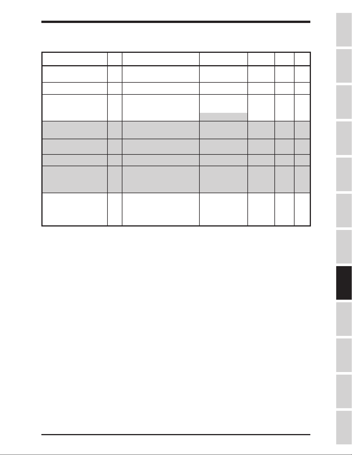
TOSHIBA
GROUP:MOTOR PARAMETERS
LIQUID CRYSTAL DISPLAY ADJUSTMENT
NUMBER OF MOTOR 316 Number of motor poles 2, 4, 6, 8, 10, 12, 14, 2 4 9-29
POLES 16
MOTOR RATED CAPACITY 317 Motor rated capacity 0.1 - 999.9 0.1kW * 9-29
ITEM
NO.
PARAMETER
DESCRIPTION
RANGE
DISPLAY
RESOLUTION
FACTORY
SETTING
PAGE
NO.
Precautions
MOTOR TYPE 318 Motor type 0: High efficiency - 0 9-29
motor
1: Standard motor
2: Other**
MOTOR RATED VOLTAGE 319** Rated voltage for 400V inverter 90 - 600 5V 400 9-29
Rated voltage for 200V inverter 90 - 600 5V 200 9-29
MOTOR RATED 320** Rated frequency 0 - 400 2 Hz 60 9-29
FREQUENCY
MOTOR RATED RPM 321** Rated RPM 0 - 9999 1 RPM 1710 9-29
AUTO-TUNING ENABLE 322** Auto-tuning *** 0: Auto-tuning - 0 9-29
disabled
1: Auto-tuning
enabled
LOAD MOMENT OF 323 Load moment of inertia 0: Small - 1 9-29
INERTIA 1: Medium
2: Large
3: Very large
*Item 317 factory setting depends on inverter rating (1 HP = .746kW)
**Items 319 - 322 are available only when Item 318 Adjustment Range option 2 is selected.
***Inverters sized 150 HP and larger cannot be auto-tuned.
Specifications
Wiring
JumpersPanelKeypadParametersProgrammingServiceDimensionsIndex Inspection
8 - 32
Page 68

Parameter Tree
Frequency
RR Terminal Standard
"OUT" Contacts Delay
RX Terminal Standard
Commercial Power Inv
"RCH" Contacts Delay
PG Terminal Standard
TOSHIBA
Fundamental
Parameters #1
1 152531436280100
Maximum Output
2 162632446381101
Base Frequency #1 Maximum Output
3 172733456482102
Base Frequency
Voltage Select
4 182834466583103
Maximum Output
Voltage #1
5 192935476684104
Reverse Operation
Disable Select
6 203036486785105
Upper Limit Freq. Stall Protection Level
7 21 37496886106
Lower Limit Freq. Acceleration Time #2 Jump Frequency #1
8 22 38506987107
Volts per hertz Pattern Deceleration Time #2 Jump Frequency #2 "RES" Input Terminal
9 23 39517088108
Voltage Boost #1 Acc/Dec Pattern #2 Jump Frequency #2
Fundamental Parameters #2Panel Control Parameters Special Control
Base Frequency #2 Direction Selection
Voltage #2
Voltage Boost #2 Fundamental Param
Electronic Thermal
Protect LVL #2
Stall Protection
Selection #2
#2
Forward/Rev
Stop Pattern Selection End Frequency "R" Input Terminal
Switching
Accel/Decel #1/#2
Selection
Panel Reset Selection Enable jump
Panel Feedback
Control
Parameters
Start up Frequency Input Terminal
Run Frequency "S1" Input Terminal
Run Frequency
Hysteresis
Frequencies
Jump Frequency #1 "S4" Input Terminal
Bandwidth
Bandwidth
Terminal Selection
Parameters
Selection
Function
Function
"S2" Input Terminal
Function
"S3" Input Terminal
Function
Function
"F" Input Terminal
Function
Function
"ST" Input Terminal
Function
Terminal Selection
Parameters (continued)
"RCH" Contacts Hold
Time
"Low" Contacts
Function
"Low" Contacts Delay
Time
"Low" Contacts Hold
Time
"FL" Contacts Function RR Reference Setting
"FL" Contacts Delay
Time
"FL" Contacts Hold
Time
"OUT" Contacts
Function
Time
Frequency Setting
Parameters
Frequency Priority
Selection #1
Frequency Priority
Selection #2
Analog Input Filter PG Ref Point #2
or Adjust.
Point #1
RR Ref Point #1
Frequency
RR reference Setting
Point #2
RR Ref Point #2
Frequency
IV Terminal Standard
or Adj.
Frequency Setting
Parameters (continued)
PG Ref Point #1
Frequency
PG Reference Setting
Point #2
Frequency
Binary Input Std. or
Adjustable
Binary Ref Setting
Point #1
Binary Ref Point #1
Frequency
Binary Ref Setting
point #2
Binary Ref Point #2
Frequency
Jog Run Frequency
10 24 40 52 71 89 109
Acceleration Time #1 Acc/Dec #1/#2 Switch
11 41 53 72 90 110
Deceleration Time #1 Jump Frequency #3
12 42 54 73 91 111
Acc/Dec Pattern #1
Selection
13 55 74 92 112
Accel/Decel Pattern
Adjust Low
14 56 75 93 113
Accel/Decel Pattern
Adjust High
Frequency
LEGEND FOR PARAMETER TREE
Unblinded Group Blinded Group
Item # Item #
Unblinded Parameter Blinded Parameter
600 V G3s HAVE ANOTHER GROUP NOT COVERED IN THIS MANUAL
Jump Frequency #3 "S5" Input Terminal
Bandwidth
PWM Carrier
Frequency
Function
"S6" Input Terminal
Function
"S7" Input Terminal
Function
Potential Terminal
Function
R, S1-S7 Terminal
Response Time
57 76 94 114
"F" Input Terminal
Response Time
58 77 95 115
"RES" Terminal
Response Time
59 78 96 116-139
"ST" Input Terminal
Response Time
60 79 97 140
"RCH" Contacts
Function
61 98 141
Time
"OUT" Contacts Hold
Time
Low Speed Signal
Output Freq
Acc/Dec Complete
Detect Band
Speed Reach Max.
Frequency
Speed Reach Min.
Frequency
Switch Output
Commercial Pwr / Inv
Switch Freq
"FP" Output Terminal
Pulse Freq.
RR Input Special
Function Select
IV Reference Setting
Point #1
IV Ref Point #1
Frequency
IV Reference Setting
Point #2
IV Ref Point #2
Frequency
or Adjust.
RX Reference Setting
Point #1
RX Ref Point #1
Frequency
RX Reference Setting
Point #2
RX Ref Point #2
Frequency
or Adjust.
Jog Stop Method
Preset Speed
Selection
Preset Speed Mode
Activation
Preset Speed #1
Frequency
Preset Speed #1
Operating Mode
Preset Speed #2
Frequency
Preset Speed #2
Operating Mode
Preset Speeds 3-14
Oper. Modes #3-14
Preset Speed #15
Frequency
Preset Speed #15
Operating Mode
8 - 33
99
PG Reference Setting
Point #1
Page 69

Protection Parameters Protection Parameters
Feedback Input Signal
Standard Setting Mode
Panel Operation Mode
Low Current Detection
Speeds 2-15 Continue
Cumulative Run Timer
Frequency Units Scale
Overload Reduction
Start Freq.
Electronic Thermal
Protect Level 1
159 313
Auto-restart (motor
speed search)
158 259 295 312
Regeneration Ride
Through time
157 258 294 311
Regeneration Power
Ride Through
156 174 257 274 293 310
Time Be tween Retry
Attempts
155 173 215 - 242 256 273 292 309
Number of Retry
Attempts
154 172 215-242 255 272 291 308
Emergency Off DC
Injection Time
153 171 214 254 271 290 307
Emergency Off Mode
Selection
152 170 213 253 270 289 306
Motor Shaft stationary
control
151 169 212 252 269 288 305
Fwd/Re v D C Inj.
Priority co nt ro l
150 168 204-211 251 268 287 304
DC Injec tion T ime Low Current Detect
149 167 203 250 267 286 303 323
DC Injec tio n Current
Magnitute
148 166 195-202 249 266 285 302 322
DC Injec tio n Start
Frequency
147 165 194 248 265 284 301 321
Overvoltage Stall
Protection
146 164 186-193 247 264 283 300 320
Braking Resistor
Power Rating
145 163 185 246 263 278 282 299 319
Branking Resistor
Value
144 162 177-184 245 262 277 281 298 318
Dynamic Braking
Selection
143 161 176 244 261 276 280 297 317
142 160 175 243 260 275 279 296 316
Parameter Tree (cont'd)
8 - 34
Alarm Setting
Override Change
Multiplier
Override Multiplier
Input Selection
Override Control
Selection
Cooling Fan Control
Selection
mode
Drooping Control
Amount
Fault Trip EEPROM
Save Enable
Speeds 2 - 15 Drive
Time
Drooping Control
Enable
Overtorque Trip Level Speed #1 Drive Time PG Input Number of
Phases
Overtorq ue T rip
Selection
Speed #1 Continue
Mode
PG Input Number of
Pulses
Output Short Circuit
Detection Select
Number of Cycles
limit
Time
Pattern Group #4
PID Deviation Lower
Pattern Group #4
Speeds #0 - #7
PID Deviation Upper
Limit
Low Current Detect
Level
Number of Cycles
Selection
Selection
Pattern Group #3
PID Deviation Limit
Pattern Group #3
Speeds #0 - #7
PID Lower Frequency
Limit
Undervoltage Detect
Time
Number of Cycles
Pattern Group #3
Lag Time Constant Master/Slave Selection Pass Number Terminal Selection
Undervoltage Trip
Selection
Pattern Group #2
Speeds #0 - #7
Anti Huntin g Gain Co mmunication
Stall Protec tio n
Current Level
Number of Cycles
Pattern Group #1
Integral Gain Inverter ID Number Current Meter
Stall Protection Enable Pattern Group #1
Speeds #0 - #7
Proportion al G a in Parity Se ttin g AM Terminal Function
Overloa d Selection Pattern Run C on tin ue
Mode
Selection
Motor 150% Overload
Time Limit
Selection
(Continued)
Pattern Run Selection Feedback Control
Pattern R u n Control
Parame te rs
Feedback Parameters Communication Setting
TOSHIBA
RS485/12-Bit Binary
pt. #2 Freq
ACC/DEC Time Units
Selection
Frequency Display
Resolution
Factor
RS485/12-Bit Binary
point #2
Status Monitor #4
Display Select
RS485/12-Bit Binary
pt. #1 Freq
Status Monitor #3
Display Select
RS485/12-Bit Binary
point #1
Status Monitor #2
display Select
RS485/12-Bit Binary
Bias, Gain
Status Monitor #1
Display Select
TOSLINE F10/S20
Comm Error Mode
Inverter TypeForm Pattern Run Control
TOSLINE F10/S20
Monitor O u tp ut
EEPROM Version Protection Function
TOSLINE F10/S20
Command Input
ROM Version Frequency Setting
RS485 Baud Rate CPU Version Special Control
Selection
Adjustment
Selection
Selection
Selection
Frequency Mode
Command Mode
Selection
Number of Data Bits Frequency Meter
Adjustment
Selection
RS232 Baud Rate FM Terminal Function
Parameters
Adjustment Parameters
AM/FM Terminal
Selection
Industrial A pp lic a tio ns Current U n its S e lection Number of Motor P ole s
Utility Parameters Utility Parameters
Motor Parameters
Blind
AM/FM Adjustment
Params B lin d
315
Industrial Appl: Tools
Blind
314
Industrial Ap p l:
Textiles B lin d
Industrial Ap p l: H o is t
Conveyor Blind
Blind
Industrial Ap p l:
Industrial Appl: Fan
Params B lin d
Industrial Appl: Pump
Params B lin d
Communication
Params B lin d
Feedback Control
Params B lin d
Params B lin d
Params B lin d
Params B lin d
Params B lin d
Load Moment of Inertia
JumpersPanelKeypadParametersProgrammingServiceDimensionsIndex Inspection
Parame te rs B lin d
Auto-Tuning Enable
Parame te rs B lin d
Motor Ra ted RPM
Frequency
Wiring
Parameters #2 Blind
Panel Control
Motor Rated
Fundamental
Motor Ra te d V o ltag e
Blind Function
Selection
Motor Type
Voltage Un its
Selection
Motor Rated Capacity
Specifications
Precautions
(Continued)
Motor Pa ra meters
Page 70

TOSHIBA
SECTION 9: Programming
Note: The H3 will "kick out" of programming mode (return to OUTPUT FREQUENCY display) when a
parameter name is displayed for fourteen seconds after the previous parameter has been read and
written.
Press the PRG button to access the H3's programming mode. The drive now displays the first of the
available groups. The H3 parameters that have related functions are gathered into families called groups.
Use the up/down arrows to scroll through the available group list.
Groups
With factory default programming, the H3 displays only three groups:
GROUP: PARAMETERS CHANGED FROM FACTORY DEFAULT
GROUP: FUNDAMENTAL PARAMETERS #1
GROUP: UTILITY PARAMETERS
The following is a list of all H3 groups:
GROUP: PARAMETERS CHANGED FROM FACTORY DEFAULT
GROUP: FUNDAMENTAL PARAMETERS #1
GROUP: FUNDAMENTAL PARAMETERS #2
GROUP: PANEL CONTROL PARAMETERS
GROUP: SPECIAL CONTROL PARAMETERS
GROUP: TERMINAL SELECTION PARAMETERS
GROUP: FREQUENCY SETTING PARAMETERS
GROUP: PROTECTION PARAMETERS
GROUP: PATTERN RUN CONTROL PARAMETERS
GROUP: FEEDBACK PARAMETERS
GROUP: COMMUNICATION SETTING PARAMETERS
GROUP: INDUSTRIAL APPLICATION PARAMETERS (PUMP)
GROUP: INDUSTRIAL APPLICATION PARAMETERS (FAN)
GROUP: INDUSTRIAL APPLICATION PARAMETERS (CONVEYOR)
GROUP: INDUSTRIAL APPLICATION PARAMETERS (HOIST)
GROUP: INDUSTRIAL APPLICATION PARAMETERS (TEXTILES)
GROUP: INDUSTRIAL APPLICATION PARAMETERS (MACHINE TOOLS)
GROUP: AM/FM TERMINAL ADJUSTMENT PARAMETERS
GROUP: UTILITY PARAMETERS
GROUP: MOTOR PARAMETERS
Programming Example 1
Objective: Set ACCELERATION TIME #1 to 23.4 seconds.
Step 1: ACCELERATION TIME #1 (Item 10) is in GROUP: FUNDAMENTAL PARAMETERS #1,
so press the PRG key and use the up/down arrows to scroll through the group list until
GROUP: FUNDAMENTAL PARAMETERS #1 is displayed.
Step 2: Press the READ/WRITE key. Drive will then display MAXIMUM OUTPUT FREQUENCY
(Item 1), because MAXIMUM OUTPUT FREQUENCY is the first parameter in
GROUP: FUNDAMENTAL PARAMETERS #1.
Step 3: Use the up/down arrows to scroll through the parameters in GROUP: FUNDAMENTAL
PARAMETERS #1 until the desired parameter (in this case, ACCELERATION TIME #1),
is displayed.
Step 4: Press the READ/WRITE key. Drive will display the value stored in this parameter.
Step 5: Adjust displayed value with up/down arrow keys. Press READ/WRITE when finished.
Drive flashes WRT to confirm entry.
Step 6: Use up/down arrows to select another parameter in this group, or press PRG to exit.
9 - 1
Page 71

Blinding
To make the H3's many parameters more manageable, Toshiba employs "blinded" parameters
and "blinded" groups.
BLINDED PARAMETERS
Item 9, VOLTAGE BOOST #1, is an example of a "blinded" parameter. A blinded parameter is
identified in the parameter charts (which start on page 8-1) by its gray shading. A "blinded"
parameter is preceded by a parameter that has a shaded choice in the Adjustment Range column
(like Item 8, VOLTS PER HERTZ PATTERN). Item 9, VOLTAGE BOOST #1, is visible to the
programmer only if item 8, VOLTS PER HERTZ PATTERN, is set to "1" or "2". Note how
Adjustment Range 1 and 2 are shaded to indicate this. There are many other blinded parameters
in the H3.
BLINDED GROUPS
Of the twenty groups in the H3, only three are accessible when the drive is programmed with
factory defaults. To adjust a parameter that is not in one of the three visible groups, that
parameter's group must first be added to the group list. This is done in GROUP: UTILITY
PARAMETERS, which is one of the visible groups.
Programming Example 2
Objective: Change ELECTRONIC THERMAL PROTECT LEVEL 1 in GROUP: PROTECTION
PARAMETERS to 89%.
Note 1: ELECTRONIC THERMAL PROTECT LEVEL 1 is in a group that is not one of the three
groups visible when the drive is programmed with factory defaults. Therefore, GROUP:
PROTECTION PARAMETERS will have to be added to the visible group list.
Note 2: GROUP: PROTECTION PARAMETERS is added to the visible group list by changing item
304, PROTECTION FUNCTION PARAMETERS BLIND in GROUP: UTILITY
PARAMETERS to "1". To change item 304, however, it must first be unblinded by setting
Item 298, BLIND FUNCTION SELECTION in GROUP: UTILITY PARAMETERS to "1".
Step 1: Press PRG and use up arrow to display GROUP: UTILITY PARAMETERS. Press READ/
WRITE key. Drive will display INDUSTRIAL APPLICATIONS because it is the first
parameter in the group.
Step 2: Instead of using the down arrow to go through all the parameters in GROUP: UTILITY
PARAMETERS, use the up arrow to make the drive display the last visible parameter in
GROUP:UTILITY PARAMETERS, which is item 298, BLIND FUNCTION SELECTION.
Step 3: Press READ/WRITE and adjust the "0" to a "1" using the arrow keys. Press READ/
WRITE again. Drive flashes WRT to confirm entry.
Step 4: Items 299-315 are now unblinded. Use the down arrow to display PROTECTION
FUNCTION PARAMETERS BLIND. Press READ/WRITE, use the up arrow to change the
"0" to a "1", and press READ/WRITE again. Drive flashes WRT to confirm entry.
Step 5: Press PRG twice to return to the group list. Use the arrows to verify that a fourth group,
GROUP:PROTECTION PARAMETERS is now a part of the group list.
Step 6: Press READ/WRITE to enter the group. Drive will display Item 142, DYNAMIC BRAKING
SELECTION because that parameter is the first in the group.
Step 7: Use the down arrow to reach Item 158, ELECTRONIC THERMAL PROTECT LEVEL 1.
Step 8: Press READ/WRITE. Using the arrows, adjust the value to "89". Press READ/WRT. Drive
flashes WRT to confirm entry.
Step 9: Press PRG to leave programming.
TOSHIBA
Precautions
Specifications
Wiring
JumpersPanelKeypadParametersProgrammingServiceDimensionsIndex Inspection
Search Function
When GROUP: PARAMETERS CHANGED FROM FACTORY DEFAULT is displayed and READ/
WRITE is pressed, the drive will display SEARCHING. Any displayed parameters have been
changed to a value different from Toshiba's default. Press READ/WRITE to see the value of the
parameter. The parameter can be modified with the up/down arrows. Pressing READ/WRITE
again resumes the drive's search.
9 - 2
Page 72

TOSHIBA
Parameter Explanations
GROUP: FUNDAMENTAL PARAMETERS #1 and GROUP: FUNDAMENTAL PARAMETERS #2 allow the
user to store unique V/Hz, accel/decel, etc. parameters for two motors to be operated on one drive at
different times.
Item 1, MAXIMUM OUTPUT FREQUENCY - This parameter cannot be changed while the motor is running,
and affects accel/decel times, binary frequency references, and many other parameters and functions. To
limit the drive's ouput frequency range, adjust UPPER LIMIT FREQUENCY and/or LOWER LIMIT
FREQUENCY (see Items 6 and 7 below).
Item 2, BASE FREQUENCY #1 - This parameter sets the frequency at which the drive's output voltage
reaches its maximum.
Item 3, BASE FREQUENCY VOLTAGE SELECTION - The parameter affects the drive's maximum output
voltage as follows:
0: The output voltage fluctuates with the input voltage.
1: The output voltage is set according to the input voltage when the drive is first powered.
2: The output voltage is set by Item 4, MAXIMUM OUTPUT VOLTAGE #1.
Item 4, MAXIMUM OUTPUT VOLTAGE #1 - This parameter sets the drive's maximum output voltage. The
output voltage cannot exceed the input voltage.
Item 5, REVERSE DISABLE OPERATION SELECTION - The drive will not run in reverse with this
parameter set to '1'.
Item 6, UPPER LIMIT FREQUENCY - This parameter sets the maximum frequency the drive will output,
regardless of reference.
Item 7, LOWER LIMIT FREQUENCY - This parameter sets the lowest speed the drive can run, regardless of reference. If this parameter is set to a non-zero value and the drive is given a run command (i.e.
F-CC closure or RUN button), the drive will run at LOWER LIMIT FREQUENCY if the reference is less
than LOWER LIMIT FREQUENCY.
Item 8, VOLTS PER HERTZ PATTERN - This parameter cannot be changed while the motor is running.
The value here sets the way the output voltage changes with output frequency:
1: Constant torque: Drive varies its output voltage linearly with its output hertz change (at 30 Hz,
output voltage is approximately half of what it is at 60 Hz).
2: Variable torque: Drive varies its output voltage as the square of its output hertz change (at 30
Hz, ouput voltage is approximately 1/4 of what it is was at 60 Hz).
3: Automatic torque boost: Drive increases its output voltage at low output Hz to increase motor
starting torque.
4: Automatic torque boost with energy saving feature: Same as number 3 above, but drive lowers
output voltage during lightly-loaded periods (reduces idle amps).
5: True torque control: Drive maximizes torque developed by motor and compensates for
motor slip. Item 298, BLIND FUNCTION SELECTION and Item 315, MOTOR PARAMETERS
BLIND, must also be set to "1" so that GROUP:MOTOR PARAMETERS can be adjusted (see
page 8-31).
6: True torque control with energy saving feature: Same as number 5 above, but drive lowers
output voltage during lightly-loaded periods (reduces idle amps).
9 - 3
Page 73

TOSHIBA
Parameter Explanations (cont'd)
Item 9, VOLTAGE BOOST #1 - This parameter increases output voltage at low Hz to enable a motor
operated in constant or variable torque modes to develop more starting torque. Too much voltage boost
could result in an overcurrent trip.
Item 10, ACCELERATION TIME #1 (AT#1)
AT#1 sets the time for drive output frequency to go from 0 Hz to MAXIMUM OUTPUT FREQUENCY
(Item 1). A small acceleration time may result in an overcurrent trip.
Item 11, DECELERATION TIME #1 (DT#1)
This parameter sets the time for drive output frequency to go from MAXIMUM OUTPUT FREQUENCY
(Item 1) to 0 Hz. A small deceleration time may result in an overvoltage trip.
Item 12, ACC/DEC PATTERN #1
This value determines the way the drive's output frequency varies with time during an accel or decel as
follows:
0: Linear pattern - Drive's output frequency change is linear with respect to time. For example, if
the output goes from 0 to 30 Hz in 5 seconds, it will take 10 seconds to go from 0 to 60 Hz.
1: Self-adjusting - Drive changes value in AT#1 and DT#1 based on current during accel and bus
voltage during decel to prevent overcurrent/overvoltage trips. Every time a run/stop is executed,
the drive changes existing data in AT#1 and DT#1 (RAM). Drive may require a few run/stop
commands to optimize value. To store modified AT#1 and DT#1 values, read value in AT#1 and
DT#1 then press READ/WRITE to write values into memory (EEPROM).
2: S pattern - Drive output frequency's rate of change is slow near beginning and end of accel/
decel.
MAXIMUM OUTPUT FREQUENCY
Precautions
Specifications
Wiring
JumpersPanelKeypadParametersProgrammingServiceDimensionsIndex Inspection
commanded frequency
OUTPUT HZ
*
AT#1
**
TIME
***
* S pattern accel time contributed by Item 13, ACCEL/DECEL PATTERN ADJUST LOW
** S pattern accel time contributed by Item 14, ACCEL/DECEL PATTERN ADJUST HIGH
*** Total S pattern accel time
Drive follows similar curve during decel.
3:
Overspeed pattern - When outputting a frequency greater than the motor's base frequency,
drive extends accel/decel time to reduce possibility of overload trip due to reduction in torque.
MAXIMUM OUTPUT FREQUENCY
commanded frequency
BASE FREQUENCY #1
OUTPUT HZ
AT#1
****
**** Actual accel time
TIME
9 - 4
Page 74

TOSHIBA
Parameter Explanations (cont'd)
Item 13, ACCEL/DECEL PATTERN ADJUST LOW - expressed as a percentage of Item 10, this time is
represented as "*" in the graph of S Pattern for Item 12.
Item 14, ACCEL/DECEL PATTERN ADJUST HIGH - expressed as a percentage of Item 10, this time is
represented as "**" in the graph of S Pattern for Item 12.
Note for GROUP:FUNDAMENTAL PARAMETERS #2
The parameters in this group are similar to those found in GROUP: FUNDAMENTAL PARAMETERS #1.
These two groups allow the user to program the drive for operation with two different motors (only one
motor connected to drive at a time). The user can determine if GROUP: FUNDAMENTAL PARAMETERS #1
or if GROUP: FUNDAMENTAL PARAMETERS #2 is active by setting Item 27, FUNDAMENTAL PARAM
SWITCHING as desired or by setting one of the drive's input terminal's function to "12" and opening/closing
that terminal to the CC terminal. The user can also determine if ACCELERATION TIME #1/DECELERA-
TION TIME #1 or ACCELERATION TIME #2/DECELERATION TIME #2 is active by setting Item 28,
ACCEL/DECEL #1/#2 SELECTION or by setting one of the drive's input terminal's functions to "9" and
opening/closing that terminal to the CC terminal. See page 9-7 for more information on programming the
input terminals.
Item 15, BASE FREQUENCY #2 - see item 2, BASE FREQUENCY #1
Item 16, MAXIMUM OUTPUT VOLTAGE #2 - see item 4, MAXIMUM OUTPUT VOLTAGE #1
Item 17, VOLTAGE BOOST #2 - see item 9, VOLTAGE BOOST #1
Item 18, ELECTRONIC THERMAL PROTECT LEVEL #2 - This parameter lowers the drive's overload to
protect the motor. Divide motor full-load amps by drive full-load amps and multiply by one hundred. Enter
the result in this parameter. Input in amps with item 296, CURRENT UNITS SELECTION, is set to "1".
Item 19, STALL PROTECTION SELECTION #2 - Stall is a drive function wherein the drive limits the
motor current by reducing output voltage and frequency in an effort to reduce load. Stall is most effective
on variable torque loads. This parameter turns stall off/on.
Item 20, STALL PROTECTION LEVEL #2 - Enter the current limit in amps or in percent of drive rating.
See Item 296, CURRENT UNITS SELECTION, to change units from % to amps.
Item 21, ACCELERATION TIME #2 - see item 10, ACCELERATION TIME #1
Item 22, DECELERATION TIME #2 - see item 11, DECELERATION TIME #1
Item 23, ACC/DEC PATTERN #2 SELECTION - see item 12, ACC/DEC PATTERN #1 SELECTION
Item 24, ACC/DEC #1/#2 SWITCHING FREQUENCY - The drive can be programmed to switch from
accel/decel time #1 to accel/decel time #2 based on output frequency. Enter the Hz at which the drive
should switch from accel/decel time #1 to accel/decel time #2.
Item 25, DIRECTION SELECTION (FORWARD/REVERSE) - This parameter determines direction when
commanding start/stop from keypad. Direction can also be changed from the keypad by pressing READ/
WRITE and the up or down arrow simultaneously (with Item 25 set to "1").
Item 26, STOP PATTERN SELECTION - This parameter determines whether the drive follows the decel
curve when the STOP button is pressed or if it performs a coast-stop. Coast stop is also performed when
ST-CC is broken.
Item 27, FUNDAMENTAL PARAM SWITCHING - This parameter determines whether GROUP:
FUNDAMENTAL PARAMETERS #1 or GROUP:FUNDAMENTAL PARAMETERS #2 is used.
9 - 5
Page 75

TOSHIBA
Parameter Explanations (cont'd)
Item 28, ACC/DEC #1 OR #2 SELECTION - If the keypad is being used for the RUN/STOP command,
then change this parameter to choose which times and pattern are currently utilized. If the drive is getting
a run/stop command via the terminal strip (i.e. "F"-"CC" made or "R"-"CC" made), the user can remotely
choose which accel/decel is used by the drive by programming one of the input terminal's functions (see
items 44-54) to a value of "9" and then closing this terminal to "CC" when acc/dec #2 is to be used. See
item 24, ACC/DEC #1/#2 SWITCH FREQUENCY to change which acc/dec time is used based on drive's
output Hz.
Item 29, PANEL RESET SELECTION - Use this parameter to limit the type of fault that can be manually
reset from the panel:
0:
Overcurrents, overloads, overvoltages, and overheat
1:
Only overload faults
2:
Only overload and overcurrent faults
Precautions
Specifications
Item 30, PANEL FEEDBACK CONTROL - Turns feedback on/off when stop/starting from keypad."0" allows
keypad to set setpoint. "1" turns feedback off, letting keypad act as a regular frequency referrence.
Item 31, START-UP FREQUENCY - Drive's output frequency remains at 0 Hz until reference commands an
output frequency greater than START-UP FREQUENCY. When the reference is great enough, drive
immediately outputs commanded frequency (no accel ramp).
Item 32, END FREQUENCY - Drive's output frequency immediately goes to 0 Hz (no decel ramp) when
reference commands an output frequency less than or equal to END FREQUENCY.
Item 33, RUN FREQUENCY (Frun) - Use in conjunction with item 34, below. This parameter is the center of
the hysteresis band.
Item 34, RUN FREQUENCY HYSTERESIS (Fhys) - Use this parameter as a +/- bandwidth around RUN
FREQUENCY. When the reference signal reaches a value that commands a frequency of Frun+Fhys, the
drive's output frequency will ramp up to the corresponding frequency. The output will continue to follow
the reference until the frequency it is commanding falls below Frun-Fhys, at which time the drive will decel
to 0 Hz.
Items 33 and 34 are not effective when PID control is operating.
HYSTERESIS CHARACTERISTIC
Wiring
JumpersPanelKeypadParametersProgrammingServiceDimensionsIndex Inspection
Frun + Fhys
Frun
Frun - Fhys
OUTPUT FREQUENCY
0
Stop
FREQUENCY REFERENCE
Start
100%
Item 35 JUMP FREQUENCY ENABLE - This parameters allows the programming of "Jump Frequencies",
which are bands of output frequencies the drive will not continuously output. The drive allows the user to
program up to three separate frequencies along with a bandwidth for each.
Item 36 JUMP FREQUENCY #1 - Enter the jump frequency.
9 - 6
Page 76

TOSHIBA
Parameter Explanations (cont'd)
Item 37 JUMP FREQUENCY BAND #1 - Enter the bandwidth for JUMP FREQUENCY #1. The value
entered here will be added to and subtracted from JUMP FREQUENCY #1 to determine the upper and
lower frequencies of the deadband.
Item 38 JUMP FREQUENCY #2 - see item 36.
Item 39 JUMP FREQUENCY BAND #2 - see item 37.
Item 40 JUMP FREQUENCY #3 - see item 36.
Item 41 JUMP FREQUENCY BAND #3 - see item 37.
Example of Jump Frequency:
Suppose JUMP FREQUENCY #1 is set to 30 Hz and JUMP FREQUENCY BAND #1 is set to 5 Hz.
Suppose a frequency reference starts commanding 0 Hz and slowly increases. The drive's output
frequency slowly increases. When the reference hits a level that is commanding 25 Hz (30 - 5 Hz),
the drive's output frequency stays at 25 Hz even though the reference continues to increase.
When the reference hits a level that commands 35 Hz (30+5 Hz), the drive accelerates (using the
selected acceleration time) from 25 Hz to 35 Hz and continues to increase as the reference
increases. During a decel, the drive will "stick" at 35 Hz until the reference hits a level that
commands 25 Hz, at which time the drive decelerates (using the selected decel time) from 35 Hz
to 25Hz, and resumes following the reference.
Item 42 PWM CARRIER FREQUENCY - Use this function to change the frequency of the motor's acoustic
noise. Derate its current capability (110%<= 8Khz, 90%>=10Khz).
Item 43 INPUT TERMINAL SELECTION - With this parameter set to "0", the drive's input terminals, when
shorted to "CC", have the following default functions:"R" terminal gives reverse run command, "F" terminal
gives forward run command, "RES" terminal resets a fault, "ST" terminal enables drive, "S1", "S2", "S3",
and "S4" terminals give preset speed references. The user has the option of changing the function assigned to any of the G3's input terminals by programming a "1" into item 43 and programming the following
parameters as necessary.
Item 44, "R" INPUT TERMINAL FUNCTION - sets the function realized when the "R" terminal isshorted
to "CC". Default setting gives a reverse run command. See page 9-9 for codes for other available
functions.
Item 45, "S1" INPUT TERMINAL FUNCTION - sets the function realized when the "S1" terminal is
shorted to "CC". Default setting gives a preset speed reference. See page 9-9 for codes for other available
functions.
Item 46, "S2" INPUT TERMINAL FUNCTION - sets the function realized when the "S2" terminal is
shorted to "CC". Default setting gives a preset speed reference. See page 9-9 for codes for other available
functions.
Item 47, "S3" INPUT TERMINAL FUNCTION - sets the function realized when the "S3" terminal is
shorted to "CC". Default setting gives a preset speed reference. See page 9-9 for codes for other available
functions.
Item 48, "S4" INPUT TERMINAL FUNCTION - sets the function realized when the "S4" terminal is
shorted to "CC". Default setting gives a preset speed reference. See page 9-9 for codes for other available
functions.
Item 49, "F" INPUT TERMINAL FUNCTION - sets the function realized when the "F" terminal is shorted
to "CC". Default setting gives a forward run command. See page 9-9 for codes for other available
9 - 7
Page 77

TOSHIBA
Parameter Explanations (cont'd)
Item 50, "RES" INPUT TERMINAL FUNCTION - sets the function realized when the "RES" terminal is
shorted to "CC". Default setting resets a fault. See page 9-9 for codes for other available functions.
Item 51, "ST" INPUT TERMINAL FUNCTION - sets the function realized when the "ST" terminal is
shorted to "CC". Default setting enables the drive. See page 9-9 for codes for other available functions.
Item 52, "S5" INPUT TERMINAL FUNCTION - sets the function realized when the "S5" terminal is
shorted to "CC". Default setting gives a binary speed reference bit. The "S5" terminal is available on the
option boards INV3-COM-B and INV3-COM-D. See page 9-9 for codes for other available functions.
Item 53, "S6" INPUT TERMINAL FUNCTION - sets the function realized when the "S6" terminal is
shorted to "CC". Default setting gives a binary speed reference bit. The "S6" terminal is available on the
option boards INV3-COM-B and INV3-COM-D. See page 9-9 for codes for other available functions.
Item 54, "S7" INPUT TERMINAL FUNCTION - sets the function realized when the "S7" terminal is
shorted to "CC". Default setting gives a binary speed reference bit. The "S7" terminal is available on the
option boards INV3-COM-B and INV3-COM-D. See page 9-9 for codes for other available functions.
Item 55, POTENTIAL TERMINAL FUNCTION - The potential terminal is an imaginary terminal that the
drive considers always shorted to "CC". Any function code from page 9-9 entered here will always be
active. For example, if a value of "10" is programmed here, the drive will always ESTOP
Notes on input terminals' functions:
1. If the same function is assigned to more than one input terminal, 'OR' logic is in effect.
2. If none of the input terminals' function is set to "7" (enable), the drive will assume the drive
enabled (just like ST-CC is made).
Precautions
Specifications
Wiring
JumpersPanelKeypadParametersProgrammingServiceDimensionsIndex Inspection
.
9 - 8
Page 78

TOSHIBA
Parameter Explanations (cont'd)
The following are the functions that are realized when the appropriate drive terminal is shorted to "CC".
Program the desired code from the list below into items 44-55 (see). Contact the factory on how to
make a function active when the terminal is disconnected from "CC" (fail-safe).
Code Function
0 Reverse direction command (default for "R" terminal function)
1 Binary coding for number of preset speed desired. Value: +1 (default for "S1" terminal function)
2 Binary coding for number of preset speed desired. Value: +2 (default for "S2" terminal function)
3 Binary coding for number of preset speed desired. Value: +4 (default for "S3" terminal function)
4 Binary coding for number of preset speed desired. Value: +8 (default for "S4" terminal function)
5 Forward direction command (default for "F" terminal function)
6 Reset faults (momentary falling-edge trigger) (default for "RES" terminal function)
7 Drive enable (default for "ST" terminal function)
8 Jog (also need direction command). See items 108 and 109.
9 Select ACC1/DEC1 (open) or ACC2/DEC2 (closed to "CC")
10 Emergency stop. Also see item 151, EMERGENCY OFF MODE SELECTION.
11 DC injection. When outputting a frequency under DC INJECTION START FREQUENCY, short
terminal to "CC" to inject. Also see items 146, 147, and 148. Works in remote mode only.
12 Activate GROUP:FUNDAMENTAL PARAMETERS #1 (open) or GROUP:FUNDAMENTAL
PARAMETERS #2 (closed to "CC")
13 PID off (closed to "CC") or on (open)
14 Select Pattern Run #1
15 Select Pattern Run #2
16 Select Pattern Run #3
17 Select Pattern Run #4
18 Pattern Run continue signal
19 Pattern Run step signal
20 Jog forward (includes forward command). See items 108 and 109.
21 Jog reverse (includes reverse command). See items 108 and 109.
22 Bit #0 for binary speed reference (value of MAXIMUM OUTPUT FREQUENCY/2048)
23 Bit #1 for binary speed reference (value of MAXIMUM OUTPUT FREQUENCY/1024)
24 Bit #2 for binary speed reference (value of MAXIMUM OUTPUT FREQUENCY/512)
25 Bit #3 for binary speed reference (value of MAXIMUM OUTPUT FREQUENCY/256)
26 Bit #4 for binary speed reference (value of MAXIMUM OUTPUT FREQUENCY/128)
27 Bit #5 for binary speed reference (value of MAXIMUM OUTPUT FREQUENCY/64)
28 Bit #6 for binary speed reference (value of MAXIMUM OUTPUT FREQUENCY/32)
29 Bit #7 for binary speed reference (value of MAXIMUM OUTPUT FREQUENCY/16)
30 Bit #8 for binary speed reference (value of MAXIMUM OUTPUT FREQUENCY/8)
31 Bit #9 for binary speed reference (value of MAXIMUM OUTPUT FREQUENCY/4)
32 Bit #10 for binary speed reference (value of MAXIMUM OUTPUT FREQUENCY/2)
33 no function (use terminal to connect wires)
34 Motor operated pot: increase frequency reference
35 Motor operated pot: decrease frequency reference
36 Motor operated pot: clear frequency reference
37 Three wire control: NO momentary start push button
38 Three wire control: NO momentary stop push button. Contact factory for information on how to
realize stop with a NC contact.
40 Forward (open) or reverse (closed to "CC") command
41 Run (use in conjunction with 40 above)
42 Binary data write (use with 22-32 above). If no input terminal's function is set to "42", the drive
responds immediately to binary references commanded by changing data bits. If one of the input
terminal's function is set to "42", the drive responds to binary reference only when terminal is
closed to "CC". Binary reference is lost when power is cycled.
43 emulate LOCAL/REMOTE key
51 Drive/bypass switching signal
53 give "RR" priority over "IV" and "RX"
54 give "IV" priority over "RR" and "RX"
9 - 9
Page 79

TOSHIBA
Parameter Explanations (cont'd)
Item 56, R,S1-S7 RESPONSE TIME - Use this function to adjust the time between an input terminal's
connection to "CC" and its function's realization. A setting of "100" results in a delay of about 200
milliseconds.
Item 57, "F" INPUT TERMINAL RESPONSE TIME - Use this function to adjust the time between an
input terminal's connection to "CC" and its function's realization. A setting of "100" results in a delay of
about 200 milliseconds.
Item 58, "RES" INPUT TERMINAL RESPONSE TIME - Use this function to adjust the time between an
input terminal's connection to "CC" and its function's realization. A setting of "100"results in a delay of
about 200 milliseconds.
Item 59, "ST" INPUT TERMINAL RESPONSE TIME - Use this function to adjust the time between an
input terminal's connection to "CC" and its function's realization. A setting of "100"results in a delay of
about 200 milliseconds.
Item 60, "RCH" CONTACTS FUNCTION - Enter the code from the table on pages 9-11 and 9-12 to
determine when drive will change the state of this dry output contact. Terminals "RCHA" and "RCHB" are
either side of the contact.
Item 61, "RCH" CONTACTS DELAY TIME - sets the delay between the time the drive senses a desired
condition and the time at which a change in "RCH" contact indicating this condition occurs. Maximum
adjustment of "100" is approximately 200 milliseconds.
Item 62, "RCH" CONTACTS HOLD TIME - Example: Suppose drive is programmed to close "RCH"
contact when it is outputting more than 30 Hz. When the drive's output frequency dips below 30 Hz, the
contact will immediately open. Adjusting this parameter to "100" would keep the "RCH" contact closed (i.e.
"RCHA" to "RCHB" shorted) for an additional 200 milliseconds after the drive outputted less than 30 Hz.
Precautions
Specifications
Wiring
JumpersPanelKeypadParametersProgrammingServiceDimensionsIndex Inspection
Item 63, "LOW" CONTACTS FUNCTION - See item 60 above.
Item 64, "LOW" CONTACTS DELAY TIME - See item 61 above.
Item 65, "LOW" CONTACTS HOLD TIME - See item 62 above.
Item 66, "FL" CONTACTS FUNCTION - See item 60 above. On terminal strip, normally open contact is
between "FLA" and "FLC". Normally closed contact is between "FLB" and "FLC".
Item 67, "FL" CONTACTS DELAY TIME - See item 61 above.
Item 68, "FL" CONTACTS HOLD TIME - See item 62 above.
Item 69, "OUT" CONTACTS FUNCTION - See item 60 above. Available on INV3-COM-B and
INV3-COM-D option boards (see page 11-4 for more information).
Item 70, "OUT" CONTACTS DELAY TIME - See item 61 above.
Item 71, "OUT" CONTACTS HOLD TIME - See item 62 above.
9 - 10
Page 80

TOSHIBA
Parameter Explanations (cont'd)
Output Contacts' Functions
Value Comments
0 Contact will close when drive is at or above Item 7, LOWER LIMIT FREQUENCY
1 Contact will close when drive is not at or above LOWER LIMIT FREQUENCY
2 Contacts will close when drive is at Item 6, UPPER LIMIT FREQUENCY
3 Contacts will close when drive is not at UPPER LIMIT FREQUENCY
4 Default for LOWA/LOWC terminals. Contact will close when drive is at or above speed in
Item 72, LOW SPEED SIGNAL OUTPUT FREQUENCY
5 Contact will close when drive is not at or above LOW SPEED SIGNAL OUTPUT FREQUENCY
6 Default for RCHA/RCHC terminals. Contact closes when any accel or decel is complete.
7 Contact closes when any acceleration or deceleration is not complete.
8 Contact closes when drive is at or above Item 74, SPEED REACH MAXIMUM FREQUENCY
during an accel or when drive is at or above Item 75, SPEED REACH MINIMUM FREQUENCY
during a decel
9 Contact closes when drive is not at or above SPEED REACH MAXIMUM FREQUENCY during an
accel or when drive is not at or above SPEED REACH MINIMUM FREQUENCY during a decel.
10 Default for FLA/FLB/FLC terminals. Contact closes when drive is faulted (ESTOP is not a fault)
11 Contact closes when drive is not faulted (ESTOP is not a fault)
12 Contact closes when drive is faulted on anything except EARTH FAULT or LOAD END
OVERCURRENT (ESTOP is not a fault)
13 Contact closes when drive is faulted on EARTH FAULT or LOAD END OVERCURRENT
14 Contact closes when overcurrent stall is active (use as overcurrent pre-alarm). The stall current
level is adjustable via Item 163 or Item 20 (see).
15 Contact closes when overcurrent stall is not active. The stall current level is adjustable via Item
163 or Item 20 (see).
16 Contact closes to signify drive overload pre-alarm. Example of drive overload: H3 is rated
for 150% of rated current for 2 minutes. If drive is operated at 150% of rated current for one
minute, the drive overload is at 50%, or half of its overload current-time capability. The drive
trips on overload at 100%. Drive overload pre-alarm starts at 50%.
17 Contact closes to signify drive is not in an overload pre-alarm. See explanation for value 16
above.
18 Contact closes to signify motor overload pre-alarm. Example of overload: H3 is rated for 150%
of rated current for 2 minutes. If drive is operated at 150% of rated current for one minute, the
drive overload is at 50%, or half of its overload current-time capability. The drive trips on
overload at 100%. Overload pre-alarm starts at 50%.
19 Contact closes to signify motor is not in an overload pre-alarm. See explanation for value 18
above.
20 Contact closes when heatsink reaches 84O C. Contact opens at 80O C after it has closed
21 Contact closes when heatsink is under 84O C. Contact closes at 80O C after it has opened
22 Contact closes when drive is displaying OVERVOLTAGE. See page 10-7.
23 Contact closes when drive is not displaying OVERVOLTAGE. See page 10-7.
24 Contact closes when drive is displaying DC BUS UNDERVOLTAGE. See page 10-7.
25 Contact closes when is not displaying DC BUS UNDERVOLTAGE. See page 10-7.
26 Contact closes when output current is at or greater than the current programmed into Item 167,
LOW CURRENT DETECTION LEVEL for longer than the time programmed in Item 168, LOW
CURRENT DETECTION TIME
27 Contact closes when output current is not at or greater than the current programmed into LOW
CURRENT DETECTION LEVEL for longer than the time programmed in LOW CURRENT
DETECTION TIME
28 Contact closes when torque current equals or exceeds the setting programmed into Item 171,
OVERTORQUE TRIP LEVEL
29 Contact closes when torque current does not equal or exceed the setting programmed into
OVERTORQUE TRIP LEVEL
Output contact functions continued on next page
9 - 11
Page 81

TOSHIBA
Parameter Explanations (cont'd)
OUTPUT CONTACTS' FUNCTIONS (con't)
Value Comments
30 Contact closes when dynamic braking resistor is half way or more into its overload as
calculated by the drive based upon the setting in Item 143, BRAKING RESISTOR VALUE and
Item 144, BRAKING RESISTOR POWER RATING (GROUP:PROTECTION PARAMETERS). See
explanation of overload for Value 16 on previous page.
31 Contact closes when dynamic braking resistor is less than half way into its overload as
calculated by the drive based upon the settings in BRAKING RESISTOR VALUE and BRAKING
RESISTOR POWER RATING. See explanation of overload for Value 17 on previous page.
32 Contact closes when drive is executing an ESTOP
33 Contact closes when drive is not executing an ESTOP
34 Contact closes when drive is executing a retry
35 Contact closes when drive is not executing a retry
36 Contact closes when drive is running a Pattern Run
37 Contact closes when drive is not running a Pattern Run
38 Contact closes when the error signal calculated by the drives PID equals or exceeds the value
programmed into Item 251, PID DEVIATION UPPER LIMIT or Item 252, PID DEVIATION
LOWER LIMIT (GROUP:FEEDBACK PARAMETERS)
39 Contact closes when the error signal calculated by the drives PID does not equal or exceed the
value programmed into PID DEVIATION UPPER LIMIT or PID DEVIATION LOWER LIMIT
40 Contact closes when drive is running at or above 0.01 Hz.
41 Contact closes when drive is not running at or above 0.01 Hz.
42 Contact closes when drive is faulted on a severe fault (not retryable) *
43 Contact closes when drive is not faulted on a severe fault *
44 Contact closes when drive is tripped on a retryable fault *
45 Contact closes when drive is not tripped on a retryable fault *
46 Auto-bypass control. Contact closes to energize coil of output contactor.
47 Opposite logic state of above
48 Auto-bypass control. Contact closes to energize coil of bypass contactor.
49 Opposite logic state of above
50 Contact closes when drives cooling fan(s) is on.
51 Contact closes when drives cooling fan(s) is not on.
52 Contact closes when drive is jogging
53 Contact closes when drive is not jogging
54 Contact closes when drive is getting RUN/STOP command from the keypad
55 Contact closes when drive is not getting RUN/STOP command from the keypad
56 Contact closes when drive run time is greater than or equal to time programmed into Item 174,
CUMULATIVE RUN TIMER ALARM SETTING (GROUP:PROTECTION PARAMETERS)
57 Contact closes when drive run time is not greater than or equal to time programmed into
CUMULATIVE RUN TIMER ALARM SETTING
58 Contact closes when drive trips on a COMMUNICATION ERROR
59 Contact closes when drive does not have a COMMUNICATION ERROR
60 Contact changes state when drive goes through 0.0 Hz to change direction. Contact is closed/
open during forward/reverse run. Contact maintains current condition at 0.0 Hz when decel is
complete after a stop command.
61 Contact changes state when drive goes through 0.0 Hz to change direction. Contact is open/
closed during forward/reverse run. Contact maintains current condition at 0.0 Hz when decel is
complete after a stop command.
62 Contact closes when drive has a run command and ST-CC is made
63 Contact closes when drive does not have a run command
Precautions
Specifications
Wiring
JumpersPanelKeypadParametersProgrammingServiceDimensionsIndex Inspection
* Retryable faults include:
OVERCURRENT(ACCEL), OVERCURRENT(DECEL), OVERCURRENT(RUN), DC OVERCURENT(ACC), DC
OVERCURRENT (DEC), DC OVERCURRENT(RUN), OVERVOLTAGE(ACCEL), OVERVOLTAGE(DECEL),
OVERVOLTAGE(RUN), OVERHEAT, MOTOR OVERLOAD, INVERTER OVERLOAD, DBR OVERLOAD TRIP
9 - 12
Page 82

TOSHIBA
Parameter Explanations (cont'd)
Item 72, LOW SPEED SIGNAL OUTPUT FREQUENCY - Use this parameter to set the frequency above
which one of the drive's output contacts (RCHA-RCHC, etc) changes state. See Item 60, 63, and 66.
Item 73, ACC/DEC COMPLETE DETECT BAND - If one of the output contacts' function is set to "6"
(accel/decel complete), use this parameter to operate the contact when the output frequency is within this
bandwidth (minus during accel, plus during decel) of the frequency command.
Item 74, SPEED REACH MAXIMUM FREQUENCY - Use this parameter to set the output frequency at which
one of the drive's output contacts (RCHA-RCHC, etc.) changes state during an acceleration. See Items
60, 63, and 66.
Item 75, SPEED REACH MINIMUM FREQUENCY - Use this parameter to set the output frequency at which
one of the drive's output contacts (RCHA-RCHC, etc.) changes state during a deceleration. See Items 60,
63, and 66.
Item 76, COMMERCIAL POWER/INVERTER SWITCHING OUTPUT - On appropriately equipped drives, use
this parameter to determine when the H3's bypass circuitry is activated:
1:
Motor runs on bypass when drive trips
2:
Motor runs on bypass when a signal is given
3:
Both of the above
Contact your Toshiba distributor for information on how to program and wire a H3 for this function.
Item 77, COMMERCIAL POWER/INVERTER SWITCHING FREQUENCY - On appropriatelyequipped
drives, use this parameter to determine the drive output frequency reached before the H3's bypass
circuitry is activated. Contact your Toshiba distributor for information on how to program and wire a
drive for this function.
Item 78, "FP" OUTPUT TERMINAL PULSE FREQUENCY - Use this parameter to set the number of
pulses per output Hz.
Item 79, RR INPUT SPECIAL FUNCTION SELECT - Use this parameter to change the function
of the 0-10 volt signal applied to the "RR" terminal:
0:
Standard (speed reference)
1:
Scale MAXIMUM OUTPUT FREQUENCY. Minimum 30 Hz
2:
Adjust multiplier on accel/decel times. Zero volts sets the multiplier to 1, 10 volts sets
the multplier to 10.
3:
Adjust voltage boost. Zero volts sets voltage boost to 0%. 10 volts set the voltage boost
to its programmed value.
4:
Current limit. Ten volts sets current limit to 150%. Contact your Toshiba distributor for
information on how to Torque Current limit.
Suggestion: set one of the monitors (Items 289-292) to a value of "14" (RR input value) to see
effective MAXIMUM OUTPUT FREQUENCY, accel/decel multiplier, effective voltage boost, or
effective STALL PROTECTION CURRENT LEVEL.
Item 80, FREQUENCY PRIORITY SELECTION #1 - use this parameter to give one of the drive's
frequency setting signals priority over another. Only when the signal set here goes to zero will the drive
follow the signal set in Item 81. If the signal selected here becomes non-zero, the drive will follow it and
ignore the signal selected in Item 81. Set this parameter to "5" when using MOP control or inputting a
binary reference via the drive's terminal strip. Preset speeds have priority over "RR" and "RX".
Item 81, FREQUENCY PRIORITY SELECTION #2 - use this parameter to give one of the drive's
frequency setting signals priority over another. Only when the signal set in Item 80 goes to zero will the
drive follow the signal set here. If the signal selected in Item 80 becomes non-zero, the drive will follow it
and ignore the signal selected here.
9 - 13
Page 83

TOSHIBA
Parameter Explanations (cont'd)
Item 82, ANALOG INPUT FILTER - Use this parameter to set the amount of filtering applied to
the drive's current/voltage frequency reference to dampen noise or resonance problems. "0" is no
filtering and "3" is maximum filtering.
Item 83, RR INPUT SELECTION - Use this parameter to allow adjustment of the RR reference's
bias and gain. Items 84 and 85 define one point on a % input reference vs. output Hz graph; Items
86 and 87 define another. The drive varies its output frequency as its input changes according to a
line connecting these points. See graph below. With default programming, drive outputs 40 Hz
with 5 volts on the "RR" terminal.
Item 84, RR REFERENCE POINT #1 - Use this parameter to set a percentage of reference.
Item 85, RR REF POINT #1 FREQUENCY - Use this parameter to set the desired drive output
Hz when its reference has the value set in Item 84 above.
Item 86, RR REFERENCE POINT #2 - Use this parameter to set a percentage of reference. The
"RR" terminal's range is 0-10 volts, so the factory default of 100% corresponds to 10 volts.
Item 87, RR REF POINT #2 FREQUENCY - Use this parameter to set the desired drive output
Hz when its reference has the value set in Item 86 above.
Bias/Gain of Frequency Input
REFERENCE POINT #2: 100%
Input Reference
Signal
Precautions
Specifications
Wiring
JumpersPanelKeypadParametersProgrammingServiceDimensionsIndex Inspection
REFERENCE POINT #1: 0%
REF POINT #2 FREQREF POINT #1 FREQ
Items 88-92, IV TERMINAL STANDARD OR ADJUSTABLE - Use these parameters to allow
adjustment of the "IV" reference's bias and gain. See explanation for Items 83-87 above. With
dipswitch in "I" position, drive considers 100% reference = 20 mA (20% would be 4 mA). With
dipswitch in "V" position, 100% reference = 10 volts. See page 5-3 for dipswitch location.
Items 93-97, RX TERMINAL STANDARD OR ADJUSTABLE - Use these parameters to allow
adjustment of the "RX" reference's bias and gain. See explanation for Items 83-87 above. With
dipswitch in "5" position, drive considers 100% reference = 5 volts. With dipswitch in "10" position,
100% reference = 10 volts. See page 5-3 for dipswitch location. Notice that the "RX" reference
can be positive or negative, and can represent a positive or negative frequency (direction change).
Items 98-102, PG TERMINAL STANDARD OR ADJUSTABLE - Use these parameters to allow
adjustment of the "PG" reference's bias and gain. See explanation for Items 83-87 above. PG
input is available on option cards INV3-COM-B and INV3-COM-D. Notice that the PG reference
can be positive or negative, and can represent a positive or negative frequency (direction change).
Items 103-107, BINARY INPUT STANDARD OR ADJUSTABLE - Use these parameters to allow
adjustment of a binary reference's bias and gain. See explanation for Items 83-87 above. Notice
that the binary reference can represent a positive or negative frequency (direction change). These
bias/gain adjustments apply to terminals programmed with values 22-32 on page 9-9.
Output Hz
80 Hz0 Hz
9 - 14
Page 84

TOSHIBA
Parameter Explanations (cont'd)
Item 108, JOG RUN FREQUENCY - Use this parameter to set the run frequency during a jog. An accel
time of zero is used, so low jog frequencies of 5 Hz or less and light loads are recommended. For
information on jogging from the keypad, see page 7-1. For information on how to jog from the terminal
strip, see pages 8-9 and 9-9. During a jog, low speed, speed reach, and PID, functions do not operate.
Item 109, JOG STOP METHOD - This parameter determines the way a jog is stopped. If DC Injection is
selected, also adjust Item 146, DC INJECTION STARTING FREQUENCY, Item 147, DC INJECTION
CURRENT, and Item 148, DC INJECTION TIME. Jog is stopped by releasing the "RUN" key (when in
panel control), and by opening "F"-"CC" or "R"-"CC" (when in remote control).
Item 110, PRESET SPEED SELECTION - Enter the total number of preset speeds to be accessed.
Item 111, PRESET SPEED MODE ACTIVATION - If this parameter is set to "1", the corresponding preset
speeds' acc/dec time selection, volts per hertz pattern selection, and direction is determined by the setting
of PRESET SPEED #<1,2,3,4,5,6,7,8,9,10,11,12,13,14,or 15> OPERATING MODE (Items 113, 115,
117, etc.). Directions commanded by closing "F"-"CC" or "R"-"CC" are effectively ignored. If Item 111 is set
to "0", the direction is determined by the terminal strip.
Items 112, 114, 116, 118, 120, 122, 124, 126, 128, 130, 132, 134, 136, 138, 140, PRESET SPEED
#<1,2,3,4,5,6,7,8,9,10,11,12,13,14,or 15> FREQUENCY - Use this parameter to set preset speed
frequencies.
Items 113, 115, 117, 119, 121, 123, 125, 127, 129, 131, 133, 135, 137, 139, 141, PRESET SPEED
#<1,2,3,4,5,6,7,8,9,10,11,12,13,14,or 15> OPERATING MODE - Use this parameter to associate a
direction and ACCELERATION TIME #1 / DECELERATION TIME #1 or ACCELERATION TIME #2 /
DECELERATION TIME #2 with a preset speed. See Item 111.
With default programming, the "S1", "S2", "S3", and "S4" terminals (see Items 45-48) are preset
speed selections via a binary implementation. Some examples:
"S4" to "CC" "S3" to "CC" "S2" to "CC" "S1" to "CC" Commanded Preset Speed #
open open open close 1
open open closed closed 3
closed closed open open 12
open closed open closed 5
closed closed closed closed 15
closed open open closed 9
closed open closed open 10
A "F"-"CC" or "R"-"CC" closure is necessary to initiate a preset speed run.
Item 142, DYNAMIC BRAKING SELECTION - Adjust this parameter when attaching a dynamic braking
resistor to the drive for increased stopping ability. A setting of "1" affords no protection for the resistor (use
for over-sized wattages, or for externally-protected resistors). A setting of "2" invokes the drive's braking
resistor protection (drive will trip on DB RESISTOR OVERLOAD if resistor is overloaded). See Items 143
and 144. For optimum use of the dynamic braking resistor, set Item 145, OVERVOLTAGE STALL
PROTECTION to "1", "off".
Item 143, BRAKING RESISTOR VALUE - Enter ohm value of resistor. See page 9-16 for
recommended DBR sizing.
Item 144, BRAKING RESISTOR POWER RATING - Enter kilowatt value of resistor. See page 9-16 for
recommended DBR sizing.
Note:
Items 142, 143, 144 are not applicable to H3 drives above 30 horsepower.
9 - 15
Page 85
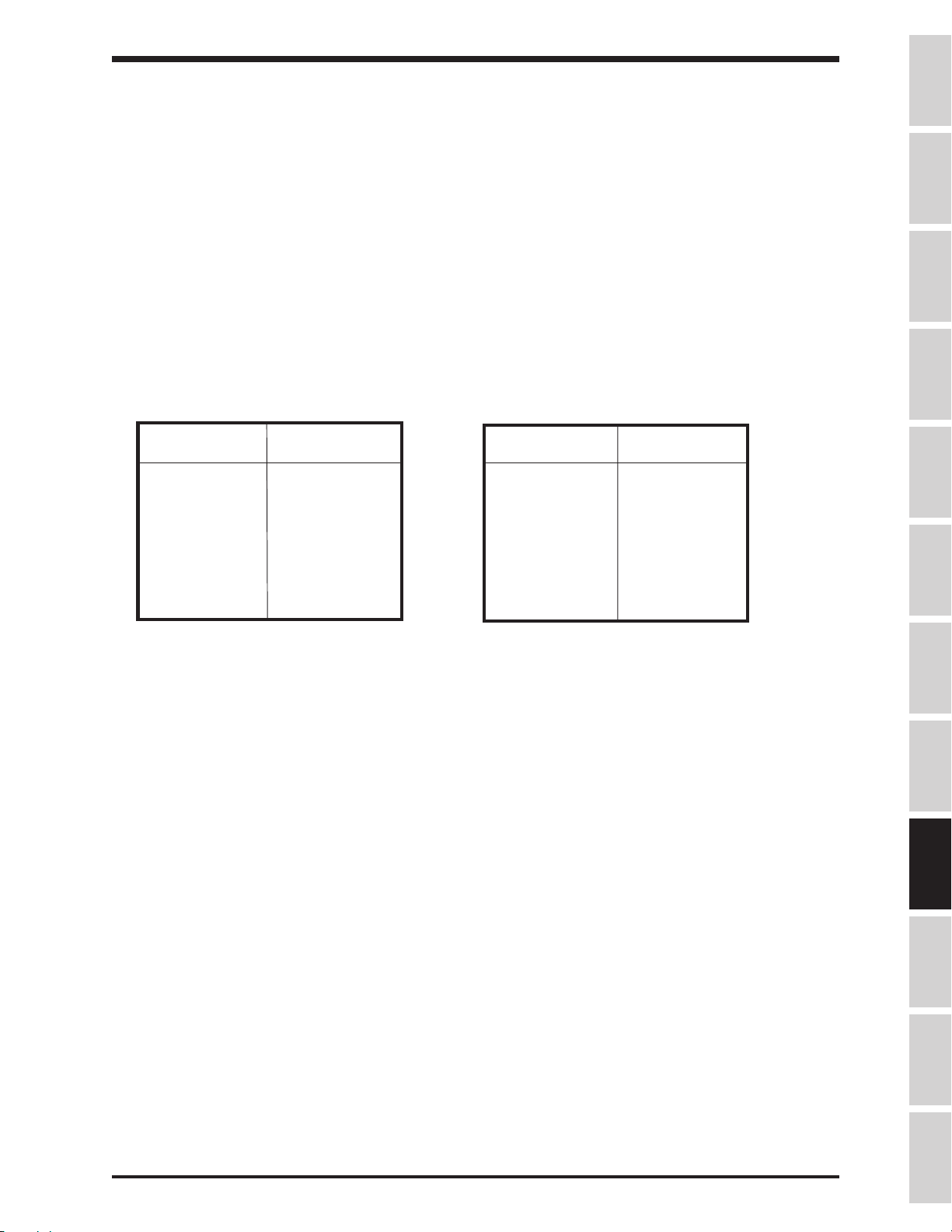
Parameter Explanations (cont'd)
TOSHIBA
DYNAMIC BRAKING
When a motor is mechanically forced to spin faster than the output frequency of the drive, the
motor acts as a generator. This regenerated energy forces current to flow into the drive's DC
bus. The bus capacitors will absorb some of the regenerative energy by charging and raising the
DC bus voltage. At high bus voltages, the drive can be programmed to fire the IGBT7 dynamic
braking transistor. This prevents a common drive fault, DC BUS OVERVOLTAGE. The dynamic
braking resistor, attached by the user to the "PA" and "PB" terminals, dissipates the bus energy
as heat when the IGBT7 fires. Two resistor values are of concern: resistance (ohms) and power
(watts). Insufficient resistance may lead to IGBT7 damage; too low of a wattage may result in
braking resistor damage from overheating.
HEAVY DUTY RESISTORS LIGHT DUTY RESISTORS
WATTS: 300 watts per drive HP WATTS: 60 watts per drive HP
H3 H.D. H3 H.D. H3 L.D. H3 L.D.
Model Ohms Model Ohms Model Ohms Model Ohms
2035 35 4055 108 2035 150 4055 360
2055 28 4080 65 2055 90 4080 240
2080 20 4110 60 2080 61 4110 180
2110 12 4160 38 2110 45 4160 120
2160 7.0 4220 30 2160 30 4220 90
2220 6.0 4270 22 2220 23 4270 70
2270 5.0 4330 20 2270 18 4330 61
2330 4.0 2330 15
(Feature not available in H3 drives above 30 horsepower)
Precautions
Specifications
Wiring
JumpersPanelKeypadParametersProgrammingServiceDimensionsIndex Inspection
Contact your Toshiba distributor for dynamic braking resistor part numbers and information.
Item 145, OVERVOLTAGE STALL PROTECTION - This function is turned on as a default setting.
Overvoltage stall protection causes the drive to automatically extend the decel time when the DC bus
voltage increases due to regeneration. The value stored in DECELERATION TIME #1 / DECELERATION
TIME #2 is not changed. The drive may still trip on overvoltage if the decel time is very small.
9 - 16
Page 86

TOSHIBA
Parameter Explanations (cont'd)
Item 146, DC INJECTION STARTING FREQUENCY - Use this parameter to set the frequency at which
DC injection begins. DC injection can be initiated remotely by programming one of the input terminals
appropriately (see Items 44-54 and page 9-9).
Item 147, DC INJECTION CURRENT - sets the current level to be employed during DC injection. Amount
can be in % of drive rating or in amps (set by Item 296).
Item 148, DC INJECTION TIME - sets the number of seconds DC is applied to the motor.
Drive will DC inject approximately 60% FLA continuously, 80% for 100 seconds, and 100% for 2
seconds without an INVERTER OVERLOAD trip.
DC injection is active when the drive's output frequency is below DC INJECTION START
FREQUENCY and the drive has a STOP command or a zero reference. DC injection is also active
when the drive's output frequency is below Item 32, END FREQUENCY.
Item 149, FWD/REV DC INJECTION PRIORITY CONTROL - When drive is running in forward
direction and is given a reverse reference, this parameter determines whether or not DC injection is active
between DC INJECTION STARTING FREQUENCY and 0 Hz. Also, a setting of "1" gives DC injection
priority over a new run command. With a setting of "0", a new run command has priority over DC injection.
Item 150, MOTOR SHAFT STATIONARY CONTROL - This parameter enables a continuous DC injection
into a stopped motor. Amps are set by DC INJECTION CURRENT / 2. Motor shaft stationary control starts
after DC injection and continues until "ST"-"CC" is opened, power is turned off, drive emergency stops, or
parameter is changed.
Item 151, EMERGENCY STOP SELECTION - This parameter determines ESTOP method.
Item 152, EMERGENCY OFF DC INJECTION TIME - This is an unique DC injection time for ESTOPs.
Item 153, NUMBER OF RETRY ATTEMPTS - The H3 can be programmed to restart after a fault occurs.
This parameter sets the number of retry attempts. Speed search is automatically on during retry. Retry will
not function if Item 172, FAULT TRIP EEPROM SAVE ENABLE is on.
Item 154, TIME BETWEEN RETRY ATTEMPTS - Adjust this parameter to set the number of seconds
between retry attempts.
Make sure that workers are not exposed to danger from
CAUTION
Item 155, REGENERATION POWER RIDE THROUGH CONTROL - H3 models 2080-2110 and 4080-4270
take control power from the DC bus; enabling this function allows use of regeneration energy from the
motor to maintain control during a brown-out. Accel/decel times may need to be adjusted to avoid
overvolltage trips. Always confirm operation.
Item 156, REGENERATION POWER RIDE THROUGH TIME - Use this parameter to limit the ridethrough time (effective only if there is sufficient regen energy).
equipment suddenly re-starting when a fault occurs and
a retry selection option other than "0" has been selected.
Item 157, AUTO-RESTART (MOTOR SPEED SEARCH) - This parameter enables the drive's ability to
catch a spinning motor:
0: Speed search off
1: Drive performs speed search after a power glitch
2: Drive performs speed search after "ST"-"CC" is made
3: Both 1 and 2 above
A drive with a forward direction command will catch a reversing motor.
9 - 17
Page 87

TOSHIBA
Parameter Explanations (cont'd)
DRIVE AND MOTOR OVERLOADS
The H3 features separate overload curves for itself and the motor. All H3s can output 110% of their rated
current continuously; current levels above 110% are considered
HP and smaller H3's overload is 150% of their rated current for 120 seconds; 125 HP and larger H3's
overload is 130% for 120 seconds. The motor's overload curve is defined by Items 158, 159, 160, and
output frequency:
Item 158, ELECTRONIC THERMAL PROTECT LEVEL 1 - use this parameter to scale the motor overload
protection to a specific motor's amp rating. Can be entered in percent or in amps, depending on the setting
of Item 296, CURRENT UNITS SELECTION. For percent setting, divide motor full load amps by drive full
load amps and multiply by 100.
overload
. The drive overload is fixed: 100
Precautions
Specifications
Item 159, OVERLOAD REDUCTION START FREQUENCY - The motor overload protection provided by the
drive is speed-sensitive by default. With default setting, a H3 at 115% of the current set by ELECTRONIC
THERMAL PROTECT LEVEL 1 will trip on MOTOR OVERLOAD sooner at 15 Hz than at 60 Hz. Users who
have allowed for reduced motor cooling at low speeds can reduce this parameter to get more overload
capability. The drive's overload protection is speed sensitive at frequencies below the value entered here.
Item 160, MOTOR 150% OVERLOAD TIME LIMIT - This parameter sets the time the drive will output
150% of the current set by Item 158, ELECTRONIC THERMAL PROTECTION LEVEL #1 before tripping
on MOTOR OVERLOAD.
Item 161, OVERLOAD SELECTION - This parameter adjusts the overload protection scheme.
0:
Standard
1:
Soft stall on. Soft stall reduces output frequency only when the drive is in its overload
region. Soft stall helps prevent drive from tripping on INVERTER OVERLOAD.
2:
Motor overload trip off.
3:
Soft stall on and motor overload trip off.
Motor overload sensing is "on" unless "2" or "3" is selected.
INVERTER OVERLOAD cooling time is approximately one minute after trip
MOTOR OVERLOAD cooling time is approximately five minutes after trip
DBR OVERLOAD cooling time is approximately thirty seconds after trip
Item 162, STALL PROTECTION ENABLE - Drive current limits when stall is turned "on".
Wiring
JumpersPanelKeypadParametersProgrammingServiceDimensionsIndex Inspection
Item 163, STALL PROTECTION LEVEL - Drive will reduce its output frequency and voltage automatically
to limit output current to the value programmed here.
Item 164, UNDERVOLTAGE TRIP SELECTION - The drive can be programmed to UNDERVOLTAGE TRIP
when the DC bus voltage is under a factory-set value by programming a "1" here. See Item 165 also. An
undervoltage alarm is available in the form of a drive output contact change; see Items 60, 63, or 66 and
setting values 24/25 on page 9-11.
Item 165, UNDERVOLTAGE DETECT TIME - The DC bus must be low for at least the time entered here
before the drive faults on UNDERVOLTAGE TRIP.
Item 166, LOW CURRENT DETECT SELECTION - The drive can be programmed to LOW CURRENT TRIP
when its output current is below the value programmed in Item 167 for at least the time programmed in
Item 168. Enter a "1" here to enable the low current detection. A low current alarm is available in the form
of a drive output contact change; see Items 60,63, or 66 and setting values 26/27 on page 9-11.
9 - 18
Page 88

TOSHIBA
Parameter Explanations (cont'd)
Item 167, LOW CURRENT DETECT LEVEL - Enter the current amount (in % or amps depending on setting
of Item 296) below which the drive will trip and/or close an appropriately-programmed output contact.
Item 168, LOW CURRENT DETECTION TIME - Enter the time the output current must be below the
amount set in Item 167 before the drive trips and/or closes an appropriately-programmed output contact.
Item 169, OUTPUT SHORT-CIRCUIT DETECTION SELECT - To protect itself, the drive does an output
short-circuit check every time a run is initiated. This parameter changes the short-circuit check:
0:
Standard setting
1:
When a low impedance motor is used, this setting desensitizes the short-circuit check,
reducing nusiance trips.
2:
This setting programs the drive to perform the check at power up only.
3:
Combination of 1 and 2 above.
Do not operate the drive on a motor with power factor correction capacitors.
Item 170, OVERTORQUE TRIP SELECTION - Enter a "1" here to program the drive to fault OVERTORQUE
TRIP based on on the torque current amount. See Item 171.
Item 171, OVERTORQUE TRIP LEVEL - Enter the torque current (in % or amps depending on the setting
of Item 296, CURRENT UNITS SELECTION) at which the drive trips and/or closes an appropriately-
programmed output contact (see Items 60,63, or 66 and setting values 28/29 on page 9-11).
Item 172, FAULT TRIP SAVING - This parameter determines the effect of cycling power on a faulted
drive:
0:
Fault and fault data cleared when drive powers up.
1:
Drive powers up in tripped state (drive display remains in faulted state, but fault data and fault
contact are not maintained).
The setting of Item 153, NUMBER OF RETRY ATTEMPTS, is ignored by the drive when Item 172 is
set to "1".
Item 173, COOLING FAN CONTROL SELECTION - This parameter determines if the drive's fan is
thermostatically-controlled or if it runs continuously.
Item 174, CUMULATIVE RUN TIMER ALARM SETTING - One of the drive's output contacts can be
programmed to change state based upon the time entered here. See Items 60,63, or 66 and setting values
56/57 on page 9-12. ".01" is one hour.
PATTERN RUN
The H3 has a feature called pattern run that emulates a low-level PLC. During a pattern run, the drive
follows a
directions with desired accel/decel times for a defined number of cycles. The H3 has 15 preset speeds,
any of which can be assigned to be speeds zero through seven in a pattern group. The drive can hold up
to four separate pattern groups, any of which can be remotely selected to run.
Item 175, PATTERN RUN SELECTION - This parameter enables pattern run. When stopping/starting
drive from panel, pattern run takes priority over the keypad's frequency reference.
pattern group
by running at the user's preset speeds for desired amounts of time in desired
Item 176, PATTERN RUN CONTINUE MODE - This parameter determines if a pattern group is continued
after a pattern run is stopped and restarted:
0:
Pattern group starts over with its first speed
1:
Pattern resumes at the time of and with the speed at interruption
9 - 19
Page 89

TOSHIBA
Parameter Explanations (cont'd)
Items 177, 186, 195, and 204, PATTERN GROUP #<1,2,3, or 4> SPEED #0 - This parameter
determines which preset speed (preset speeds 1 through 15 programmed in Items 110-141) is the first
speed in the pattern group. Unlike the other speeds #1 - #7, speed #0 is not repeated when PATTERN
GROUP #<1,2,3, or 4> NUMBER OF CYCLES is greater than one. Set this parameter to "0" to skip this
speed.
Items 178, 187, 196, 205, PATTERN GROUP #<1,2,3, or 4> SPEED #1 - This parameter determines
which preset speed (preset speeds 1 through 15 programmed in Items 110-141) is the next speed in the
pattern group. Speed #1 can be but does not have to be Preset Speed #1.
Precautions
Items 179, 188, 197, 206, PATTERN GROUP #<1,2,3, or 4> SPEED #2 - This parameter determines
which preset speed (preset speeds 1 through 15 programmed in Items 110-141) is the next speed in the
pattern group. Speed #2 can be but does not have to be Preset Speed #2.
Items 180, 189, 198, 207, PATTERN GROUP #<1,2,3, or 4> SPEED #3 - This parameter determines
which preset speed (preset speeds 1 through 15 programmed in Items 110-141) is the next speed in the
pattern group. Speed #3 can be but does not have to be Preset Speed #3.
Items 181, 190, 199, 208, PATTERN GROUP #<1,2,3, or 4> SPEED #4 - This parameter determines
which preset speed (preset speeds 1 through 15 programmed in Items 110-141) is the next speed in the
pattern group. Speed #4 can be but does not have to be Preset Speed #4.
Items 182, 191, 200, 209, PATTERN GROUP #<1,2,3, or 4> SPEED #5 - This parameter determines
which preset speed (preset speeds 1 through 15 programmed in Items 110-141) is the next speed in the
pattern group. Speed #5 can be but does not have to be Preset Speed #5.
Items 183, 192, 201, 210, PATTERN GROUP #<1,2,3, or 4> SPEED #6 - This parameter determines
which preset speed (preset speeds 1 through 15 programmed in Items 110-141) is the next speed in the
pattern group. Speed #6 can be but does not have to be Preset Speed #6.
Items 184, 193, 202, 211, PATTERN GROUP #<1,2,3, or 4> SPEED #7 - This parameter determines
which preset speed (preset speeds 1 through 15 programmed in Items 110-141) is the next speed in the
pattern group. Speed #7 can be but does not have to be Preset Speed #7.
Specifications
Wiring
JumpersPanelKeypadParametersProgrammingServiceDimensionsIndex Inspection
Items 185, 194, 203, 212, PATTERN GROUP #<1,2,3, or 4> NUMBER OF CYCLES - This parameter
determines how many times the pattern group made up of speeds #1 through #7 entered in the above
parameters will be repeated.
Items 213, 215, 217, 219, 221, 223, 225, 227, 229, 231, 233, 235, 237, 239, and 241,
SPEED #<1,2,3,4,5,6,7,8,9,10,11,12,13,14,or 15> CONTINUE MODE. This parameter affects the timing
of the speeds in a pattern group:
0:
Preset speed's time is counted in
included in the time entered in the following parameter, SPEED
#<1,2,3,4,5,6,7,8,9,10,11,12,13,14,or 15> DRIVE TIME
1: Preset speed's time is counted in
included in the time entered in the following parameter, SPEED
#<1,2,3,4,5,6,7,8,9,10,11,12,13,14,or 15> DRIVE TIME
2: Preset speed's time is counted in
not included in the time entered in the following parameter, SPEED
#<1,2,3,4,5,6,7,8,9,10,11,12,13,14,or 15> DRIVE TIME
3: Preset speed's time is counted in
not included in the time entered in the following parameter, SPEED
#<1,2,3,4,5,6,7,8,9,10,11,12,13,14,or 15> DRIVE TIME
4:
Non-stop (stop by breaking ST-CC or F-CC or R-CC).
5:
Drive waits for step command to change speeds. See Items 45-54 and setting value 19
on page 9-9.
seconds
minutes
seconds
minutes
from the beginning of the run (accel/decel time is
from the beginning of the run (accel/decel time is
after preset speed is reached (accel/decel time is
after preset speed is reached (accel/decel time is
9 - 20
Page 90

TOSHIBA
Parameter Explanations (cont'd)
Items 214, 216, 218, 220, 222, 224, 226, 228, 230, 232, 234, 236, 238, 240, and 242, SPEED NUMBER
<1,2,3,4,5,6,7,8,9,10,11,12,13,14, or 15> DRIVE TIME - This parameter determines the
amount of time associated with each
preceding parameter.
Item 243, FEEDBACK CONTROL SELECTION - This parameter programs the drive to operate in PID
mode (maintain a process variable such as pressure), speed feedback, or in normal mode.
Item 244, FEEDBACK INPUT SIGNAL SELECTION - This parameter programs the drive to accept
feedback at one of many possible inputs:
1:
"RR" terminal
2:
"IV" terminal
3:
"RX" terminal
4:
Pulse generator input (on option board INV3-COM-B or INV3-COM-D)
5:
RS232 port
6:
RS485 port or 12 bit input (on option board INV3-COM-A, INV3-COM-C or
G3-VF5X-4526A
7:
Binary input ( via input terminals programmed appropriately - see Items 45-54 and
setting values 22-32 on page 9-9).
preset
speed. The time unit (minutes/seconds is determined by the
Item 245, PROPORTIONAL GAIN - The larger the value here, the quicker the drive responds to changes
in feedback. Contact Houston for the PID application guideline. READ/WRITE does not have to be
pressed to make the value entered here effective.
Item 246, INTEGRAL GAIN - Also known as reset, this parameter is actually a time. The smaller the
value here, the more pronounced the effect of the integral function. Contact Houston for the PID
application guideline. READ/WRITE does not have to be pressed to make the value entered here
effective.
Item 247, ANTI-HUNTING GAIN - Also known as differential gain or rate, this parameter is actually a
time. The larger the value here, the more pronounced the effect of the differential function. Contact
Houston for the PID application guideline. READ/WRITE does not have to be pressed to make the value
entered here effective.
Item 248, LAG TIME CONSTANT - This parameter effects drive reaction time to change in feedback
value. Decrease this setting to improve drive response.
Item 249, PID LOWER LIMIT FREQUENCY - When PID is active, Item 7, LOWER LIMIT FREQUENCY
is not effective. This parameter is the lower limit when PID is active. Some drives have a version of keypad
ROM that does not contain this parameter (version 100). If drive cannot display this parameter, see
section 7.4 about identifying keypad ROM version. Keypad ROM versions 110 and 121 contain Item 249.
Item 250, PID DEVIATION LIMIT SELECTION - The amount of correction calculated by the drive can
be limited to control possible system oscillations. Place a "1" here to PID deviation limit.
Item 251, PID DEVIATION UPPER LIMIT - The amount of correction calculated by the drive is limited
to the value entered here, expressed in terms of percent of Item 1, MAXIMUM OUTPUT FREQUENCY.
Item 252, PID DEVIATION LOWER LIMIT - The amount of correction calculated by the drive is limited
to the value entered here, expressed in terms of percent of Item 1, MAXIMUM OUTPUT FREQUENCY.
Item 253, PG INPUT: NUMBER OF PULSES - When an encoder and PG option board (INV3-COM-B or
INV3-COM-D) is being used for closed loop speed control, enter pulses per revolution. When using option
board to follow a pulse reference, enter number of pulses that correspond to a frequency command of one
hertz. See the Extended Terminal Block Option Manual for more information.
9 - 21
Page 91

TOSHIBA
Parameter Explanations (cont'd)
Item 254, PG INPUT: NUMBER OF PHASES - Use this parameter to select either one or two phase
encoder feedback. See the Extended Terminal Block Option Manual for more information.
Item 255, DROOPING CONTROL ENABLE - Use this parameter to enable the H3's load share function,
which continuously stalls based on load. This parameter can be changed while the drive is at a non-zero
output frequency, but the change does not go into effect until drive is stopped.
Item 256, DROOPING CONTROL AMOUNT - Use this parameter to set the maximum amount of droop (in
percent of Item 1, MAXIMUM OUTPUT FREQUENCY).
Precautions
When drooping, Output Frequency = Reference Frequency - Droop
Droop = MAXIMUM OUTPUT FREQUENCY x DROOPING CONTROL AMOUNT x Torque Ratio
Torque Ratio (maximum value of 2.0)= operating torque / rated torque
Item 257, OVERRIDE CONTROL SELECTION - Use this parameter to create a "trim pot". The "trim pot"
function allows a user to uniquely adjust the speed of a drive that is receiving a master reference. The
bias/gain of these inputs determines their effect on the master reference (see Items 84-107). Select which
one of the H3's frequency references will serve as the trim source:
0:
none
1:
"RR" terminal
2:
"IV" terminal
3:
"RX" terminal (+/- trim possible)
4:
Pulse generator input on option card INV3-COM-B or INV3-COM-D (+/- trim possible)
5:
H3 keypad
6:
RS485 input or 12-bit input on option cards INV3-COM-A , INV3-COM-C, or G3-VF5X-4526A
7:
Trim source with multiplier. See Items 258 and 259 below.
Item 258, OVERRIDE MULTIPLIER INPUT SELECTION - When used with a multiplier, the
following inputs' bias and gain do not determine their effect on the master reference. Select which
of the following trim sources will be used with the muliplier:
0:
Frequency reference
1:
"RR" terminal
2:
"IV" terminal
3:
"RX" terminal
4:
RS485 input or 12-bit input on option cards INV3-COM-A, INV3-COM-C, or G3-VF5X-4526A
Specifications
Wiring
JumpersPanelKeypadParametersProgrammingServiceDimensionsIndex Inspection
Item 259, OVERRIDE CHANGE MULTIPLIER - When Item 258 is set to "0", this parameter sets the
percent of reference to be added/subtacted to/from the reference. When Item 258 is set to "1", "2", "3", or
"4", the value entered here determines the maximum range of trim in terms of percentage of reference.
This maximum range of trim includes both positive and negative trim bandwidths. Any amount of trim up to
this maximum is available by changing the trim terminal's input. Maximum negative trim is achieved with
minimum input on trim terminal. Maximum positive trim is achieved with maximum input on trim terminal.
Example: Suppose Item 258 is set to "1" (RR trim), Item 259 is set to "25%", and a 4-20 mA
reference into the "IV" terminal is commanding 40 Hz. When the "RR" input is 0 volts, the drive
outputs 35 Hz (40 - ((40 X 0.25)/2)). When the "RR" input is adjusted to 10 volts, the drive outputs
45 Hz (40 + ((40 X 0.25)/2)).
Item 260, RS232 BAUD RATE - sets baud rate. Cycle power after changing this parameter.
Item 261, NUMBER OF DATA BITS - sets the word length. Cycle power after changing.
Item 262, PARITY SETTING - sets the parity. Cycle power after changing this parameter.
Item 263, INVERTER ID NUMBER - assigns unique ID to drive for use on RS485 net. Cycle power after
changing this parameter.
9 - 22
Page 92

TOSHIBA
Parameter Explanations (cont'd)
Item 264, COMMUNICATION SELECTION - Use this parameter to select type of communication:
0:
None
1:
RS485 port on option boards INV3-COM-A, INV3-COM-C, or INV3-COM-B
2:
Toshiba TOSLINE F10 (twisted pair). Contact your Toshiba distributor for more information
3:
Toshiba TOSLINE S20 (fiber optic). Contact your Toshiba distributor for more information.
4:
12 bit binary reference using option card G3-VF5X-4526A
5:
Three digit BCD input on card G3-VF5X-4526A ( 0.1 Hz resolution )
6:
Three digit BCD input on card G3-VF5X-4526A ( 1.0 Hz resolution )
Cycle power after changing this parameter.
Item 265, MASTER/SLAVE SELECTION - This parameter defines the drive's role in the master/
follower scenario. A value of "1" entered here will make followers follow the frequency command
the master is receiving (master may be stopped while the followers run). A value of "2" entered
here will make the followers run according to the master's output frequency. Cycle power after
changing this parameter.
Item 266, RS485 BAUD RATE - In conjunction with jumpers J1 ands J2 on the RS485 option
board used, this parameter sets the
RS485 baud rate
as follows:
Position of Setting of Item 266
J1 J2 0 1
off off
on off
off on
on on
INV3-COM-A and INV3-COM-B cards' max baud is 19200.
INV3-COM-C card's max baud is 38400.
Cycle power after changing this parameter.
Item 267, TOSLINE F10/S20 COMMAND INPUT - determines if drive accepts run/stop and/or
frequency commands from TOSLINE. Contact PLC marketing for more information. Cycle power
after changing this parameter.
Item 268, TOSLINE F10/S20 MONITOR OUTPUT - determines the drive operating data to be
communicated. Contact PLC marketing for more information. Cycle power after changing this
parameter.
Item 269, TOSLINE F10/S20 COMM ERROR MODE - When set to a value of "0", a zero speed
command is commenced in the event of an error. A value of "1" the data prior to the error is held.
Cycle power after changing this parameter.
Items 270-274 , RS485/12-BIT BINARY BIAS, GAIN - use these parameters to allow
adjustment of the RS485 or 12 bit reference's bias and gain. See explanation for Items 83-87
above. Follower's 100% reference is master's Item 1, MAXIMUM OUTPUT FREQUENCY. RS485 input is
available on option cards INV3-COM-A, INV3-COM-B, and INV3-COM-C. 12 bit binary input is available
on option card G3-VF5X-4526A. Cycle power after changing this parameter.
9600 38400
4800 19200
2400 9600
1200 4800
Item 275, FM TERMINAL FUNCTION SELECTION - This parameter determines the drive
operating variable associated with the 0-1 mA/4-20 mA signal from the "FM" and "CC" terminals.
The "FM" output is user-selected as 0-1 mA or 4-20 mA by setting JP3 (to the left of the terminal
strip) in the appropriate position (see page 5-2).
Do not make connections to this terminal with the
drive powered.
(continued next page)
9 - 23
Page 93

TOSHIBA
Parameter Explanations (cont'd)
Item 275, FM TERMINAL FUNCTION SELECTION (con't) - Choices for "FM" terminal's signal's
function:
0: (
default for "FM"). Pre-compensation reference frequency. This is the drive's internal
frequency command and is affected by acc/dec and PID and droop (same as the actual output
frequency displayed on the drive's keypad).
1:
Post-compensation output frequency may be higher than frequency command (drive
overspeeds to compensate for slip in vector control).
2:
Frequency command. Use for master/follower. Not affected by stopping or accel/decel.
3:
(default for "AM"). Output current. (output amps)2 =(torque amps)2+(excitation amps)
4:
DC bus voltage
5:
Output voltage
6:
Torque current. (output current)2 = (torque current)2 + (excitation current)
7:
Excitation current. (output current)2 = (torque current)2 + (excitation current)
8:
PID feedback value. This is the frequency represented by the feedback signal
9:
Motor overload ratio. Example: H3 is rated for 150% FLA for 2 minutes. If H3 runs at
150% for 1 minute, this output will be 50%. Drive trips when ration hits 100%.
10:
Inverter overload ratio. See example for selection 9 above.
11:
Dynamic braking resistor overload ratio. See example for selection 9 above.
12:
Input power (watts)
13:
Output power (watts)
14:
Meter calibration setting
15:
Peak output current. Peak is reset by cycling power, initiating a run, or resetting drive.
16:
Peak input voltage. Peak is reset by cycling power, initiating run, or resetting drive.
Calculated from DC bus.
2
2
Precautions
2
Specifications
Wiring
JumpersPanelKeypadParametersProgrammingServiceDimensionsIndex Inspection
Item 276, FREQUENCY METER ADJUSTMENT - This setting adjusts the gain of the "FM" terminal. With
Item 275 set to "14" (or Item 277 for the "AM" terminal), press the up/down arrows (ignoring parameter
value shown) until external meter/system reads the following value for the chosen operating variable:
For
post compensation frequency,
adjust until meter/system reads 75% of Item 1, MAXIMUM
OUTPUT FREQUENCY
For
post-compensation output frequency,
adjust until meter/system reads 75% of Item 1,
MAXIMUM OUTPUT FREQUENCY
For
frequency command,
adjust until meter/system reads 75% of Item 1, MAXIMUM OUTPUT
FREQUENCY
For
output current,
For
DC bus voltage,
adjust until meter/system reads drive rated amps (or 100%)
adjust until meter/system 283 VDC for a 230 V drive or 566 VDC for a 460 V
drive.
For
output voltage,
adjust arrows until meter/system reads 200 VAC (or 100%) for a 230 V drive
or 400 VAC (or100%) for a 460 V drive.
For
torque current,
For
excitation current,
For
PID feedback value,
adjust arrows until meter/system reads drive rated amps (or 100%).
adjust arrows until meter/system reads drive rated amps (or 100%).
adjust arrows until meter/system reads 75% of Item 1, MAXIMUM
OUTPUT FREQUENCY.
For
motor overload ratio,
For
inverter overload ratio,
For
dynamic braking resistor overload ratio,
For
input power,
adjust arrows until meter/system reads 346 X drive FLA for a 230 V driveor 692
adjust arrows until meter/system reads 100%.
adjust arrows until meter/system reads 100%.
adjust arrows until meter/system reads 100%.
X drive FLA for a 460 V drive.
For
output power,
adjust arrows until meter/system reads 346 X drive FLA for a 230 V drive or
692 X drive FLA for a 460 V drive.
For
peak output current,
For
peak input voltage,
adjust arrows until meter/system reads drive rated amps (or 100%).
adjust arrows until meter/system reads 200 VAC for a 230 V drive or 400
VAC for a 460 V drive.
9 - 24
Page 94

TOSHIBA
Parameter Explanations (cont'd)
Item 277, AM TERMINAL FUNCTION SELECTION - This parameter is programmed like Item 275, but it
affects the "AM" terminal.
Item 278, AMMETER ADJUSTMENT - This parameter is programmed like Item 276, but it affects the "AM"
terminal.
Item 279, INDUSTRIAL APPLICATION SELECTION - This parameter can be changed only when the
drive's output is 0.0 Hz.When programmed with a non zero value, the drive will initialize itself (prior programming is erased) to parameter values that lend themselves to specific applications. Contact your
Toshiba distributor for a copy of the Industrial Application Manual which lists the specific parameter setting
by application macro. When read, this parameter displays two values; the one on the left is the previous
value, while the one on the right is the current value.
Item 280, STANDARD SETTING MODE SELECTION - This parameter can be changed only when the
drive's output is 0.0 Hz. When read, this parameter displays two values; the one on the left is the previous
value, while the one on the right is the current value. This parameter resets the parameter values of the
drive as follows:
1: Default drive to typical 50 Hz application settings.
2: Default drive to typical 60 Hz application settings.
3: Default drive to Toshiba factory settings listed in "Factory Setting" column on pages 8-1 through
8-32. Past four faults in the monitor erased.
4: Erase past four faults in the monitor.
5:
Save present parameter settings in separate "user" default memory.
6:
Default drive to "user" default memory.
7:
Clear INVERTER TYPEFORM ERROR (also defaults drive to factory values).
Item 281, COMMAND MODE SELECTION - Changes to this parameter go into effect only when the drive is
at 0.0 Hz. This parameter determines where the drive looks for a stop/start command:
0: RS232 port
1: H3 terminal strip only (remote mode)
2: H3 keypad stop/start buttons only (local mode)
3: RS485 input on option boards INV3-COM-A, INV3-COM-B, or INV3-COM-C
4:
Local or remote as determined by setting of LOCAL/REMOTE button on keypad
Terminal strip enable, reset, and ESTOP commands are always valid, regardless of Item 281's
setting. With this parameter set to "2", preset speeds from terminal strip will not function.
Item 282, FREQUENCY MODE SELECTION - Changes to this parameter go into effect only when the drive
is at 0.0 Hz. This parameter determines where the drive looks for its output frequency reference:
0: RS232 port
1: H3 terminal strip only (remote mode)
2: H3 keypad stop/start buttons only (local mode)
3: RS485 or 12 bit binary input on option boards INV3-COM-A, INV3-COM-B,
INV3-COM-C, or VF5X-4526A
4:
Local or remote as determined by setting of LOCAL/REMOTE button on keypad
Terminal strip enable, reset, and ESTOP commands are always valid, regardless of Item 282's
setting.
9 - 25
Page 95

TOSHIBA
Parameter Explanations (cont'd)
Item 283, PANEL OPERATION MODE SELECTION - Cycle power after changing this parameter.
This parameter limits what can be done via the keypad. Panel ESTOP in remote mode is ALWAYS valid.
The values entered here that are zero or are a power of two have one function assigned to them:
0: Keypad does nothing 1: Reset drive fault only
2: Monitor only
8:
Run/Stop only
32:
Change parameters only
The rest of the possible parameter values are combinations of the above.
Note: to "change parameters only", "read parameters only" must also be selected.
TO RESET AFTER "0" HAS BEEN PROGRAMMED IN ITEM 283:
1. Press four keys simultaneously: LOCAL/REMOTE, PRG, READ/WRITE, and
2. Drive will display ENTER PASS NUMBER 0
3. Pass number is programmed in Item 284, PASS NUMBER. Enter pass number with
arrows and hit READ/WRT.
4. If entered correctly, PASS NUMBER ENTERED CORRECTLY will display briefly and Item
283 will be reset to a value of 63, allowing all keypad operations.
4:
ESTOP only
16:
Read parameters only
up arrow
Precautions
Specifications
Wiring
If ENTER PASS NUMBER doesn't appear after pressing the four keys, cycle power and try again.
Item 284, PASS NUMBER - Incorrect entry of the setting in this parameter prevents resetting
keypad lockout (Item 283 set to "0"). Item 284 is viewable through RS232 port.
Item 285, CPU VERSION - This is a read-only parameter. This manual is for the version 120 CPU. Version
120 added the following features to version 5101: input terminal functions 52,53, and 54; output terminal
functions 62 and 63; "RR" special input function #4; PID lower limit, peak voltage, peak current, and
calibration settings for AM/FM terminal functions; peak voltage and peak current monitor choices;
drooping control.
Item 286, ROM VERSION - This is a read-only parameter. "5120" is the default setting with a
version 120 CPU (230/460 volt drive). Application-specific option ROMs are available from Toshiba.
Item 287, EEPROM VERSION - This read-only parameter shows control board EEPROM version.
Item 288, INVERTER TYPEFORM - This read-only parameter identifies the drive model number:
Typeform Model Typeform Model
24 H3U2035
25 H3U2055 26 H3U2080
27 H3U2110 28 H3U2160
29 H3U2220 2A H3U2270
2B H3U2330
45 H3U4055 46 H3U4080
47 H3U4110 48 H3U4160
49 H3U4220 4A H3U4270
4B H3U4330 4C H3U4400
4D H3U4500 4E H3U4600
4F H3U4750 50 H3U410K
51 H3U412K 52 H3U415K
53 H3U420K 54 H3U425K
55 H3U430K
JumpersPanelKeypadParametersProgrammingServiceDimensionsIndex Inspection
9 - 26
Page 96

TOSHIBA
Parameter Explanations (cont'd)
Items 289-292, STATUS MONITOR #<1,2,3,and 4> SELECT - Pressing MON button displays the drive's
monitor mode. See Item 296 to display currents in amps or percent. See Item 297 to display voltages in
volts or percent. The drive operation variable displayed in four of the monitor mode's screens are
selectable:
1:
Post-compensation output frequency may be higher than frequency command (drive
overspeeds to compensate for slip in vector control).
2:
Frequency command. Not affected by stopping or accel/decel.
Default for STATUS MONITOR #1 DISPLAY SELECT
3:
Output current. (output amps)2 =(torque amps)2+(excitation amps)
Default for STATUS MONITOR #2 DISPLAY SELECT
4:
Input voltage (calculated from DC bus voltage). If displayed in percent, note that 230 V drives
consider 200 V to be 100% input and 460 V drives consider 400 V to be 100% input.
Default for STATUS MONITOR #3 DISPLAY SELECT
5:
Output voltage. If displayed in percent, note that 230 V drives consider 200 V to be 100% output
and 460 V drives consider 400 V to be 100% output.
Default for STATUS MONITOR #4 DISPLAY SELECT
6:
Torque current. (output current)2 = (torque current)2 + (excitation current)
7:
Excitation current. (output current)2 = (torque current)2 + (excitation current)
8:
PID feedback value. This is the frequency represented by the feedback signal
9:
Motor overload ratio. Example: H3 is rated for 150% FLA for 2 minutes. If drive runs at 150%
for one minute, this output will be 50%. Drive trips when ration hits 100%.
10:
Inverter overload ratio. See example for selection 9 above.
11:
Dynamic braking resistor overload ratio. See example for selection 9 above.
12:
Input power
13:
Output power
14:
"RR" terminal input value (the variable displayed here varies with the setting of Item 79, RR
INPUT SPECIAL FUNCTION SELECT).
15:
Peak output current. Peak is reset by cycling power, initiating a run, or resetting drive.
16:
Peak input voltage. Peak is reset by cycling power, initiating run, or resetting drive.
Calculated from DC bus. If displayed in percent, note that 230 V drives consider 200 V input to
be 100% and that 460 drives consider 400 V input to be 100%.
2
2
2
Item 293, FREQUENCY UNITS SCALE FACTOR - Drive's frequency output display can be scaled by
putting a non-zero value here. Drive's display will still read OUTPUT FREQUENCY, but HZ will no longer be
visible.
Item 294, FREQUENCY DISPLAY RESOLUTION - Use this parameter to select the number of decimal
points for keypad's output frequency display.
Item 295, ACC/DEC TIME UNITS SELECTION - Affects Items 10,11,21, and 22 (sets resolution of
accel/decel times).
Item 296, CURRENT UNITS SELECTION - With this parameter set to "1", drive displays currents in amps.
Item 297, VOLTAGE UNITS SELECTION - With this parameter set to "0", the voltages displayed in the
monitor are in percent.
Item 298, BLIND FUNCTION SELECTION - Page 8-31 contains the parameters that unblind the H3's
programming groups. Item 298 must be set to "1" before Items 299-315 can be read or changed.
Item 299, FUNDAMENTAL PARAMS #2 BLIND - This parameter must be set to "1" before any of the
parameters on page 8-2 can be read or changed. Putting a "1" here adds GROUP: FUNDAMENTAL
PARAMETERS #1 to the group list (accessed via the PRG button).
9 - 27
Page 97

TOSHIBA
Parameter Explanations (cont'd)
Item 300, PANEL CONTROL PARAMS BLIND - This parameter must be set to "1" before any of the
parameters on page 8-3 can be read or changed. Putting a "1" here adds GROUP:PANEL CONTROL
PARAMETERS to the visible group list (accessed via the PRG button).
Item 301, TERMINAL SELECTION PARAMS BLIND - This parameter must be set to "1" before any of the
parameters on pages 8-5 through 8-7 can be read or changed. Putting a "1" here adds GROUP:TERMINAL
SELECTION PARAMETERS to the visible group list (accessed via the PRG button).
Item 302, SPECIAL CONTROL PARAMS BLIND - This parameter must be set to "1" before any of the
parameters on page 8-3 can be read or changed. Putting a "1" here adds GROUP:SPECIAL CONTROL
PARAMETERS to the visible group list (accessed via the PRG button).
Item 303, FREQUENCY SETTING PARAMS BLIND - This parameter must be set to "1" before any of the
parameters on pages 8-8 through 8-12 can be read or changed. Putting a "1" here adds
GROUP:FREQUEMCY SETTING PARAMETERS to the visible group list (accessed via the PRG button).
Item 304, PROTECTION FUNCTION PARAMS BLIND - This parameter must be set to "1" before any of
the parameters on pages 8-13 through 8-15 can be read or changed. Putting a "1" here adds
GROUP:PROTECTION FUNCTION PARAMETERS to the visible group list (accessed via the PRG button).
Item 305, PATTERN RUN CONTROL PARAMS BLIND - This parameter must be set to "1" before any of
the parameters on pages 8-16 through 8-21 can be read or changed. Putting a "1" here adds
GROUP:PATTERN RUN CONTROL PARAMETERS to the visible group list (accessed via the PRG button).
Item 306, FEEDBACK CONTROL PARAMS BLIND - This parameter must be set to "1" before any of the
parameters on pages 8-22 through 8-23 can be read or changed. Putting a "1" here adds
GROUP:FEEDBACK CONTROL PARAMETERS to the visible group list (accessed via the PRG button).
Item 307, COMMUNICATION PARAMETERS BLIND - This parameter must be set to "1" before any of the
parameters on pages 8-24 through 8-25 can be read or changed. Putting a "1" here adds
GROUP:COMMUNICATION PARAMENTERS to the visible group list (accessed via the PRG button).
Precautions
Specifications
Wiring
JumpersPanelKeypadParametersProgrammingServiceDimensionsIndex Inspection
Item 308, INDUSTRIAL APPL: PUMP PARAMS BLIND - Putting a "1" here adds GROUP:INDUSTRIAL
APPLICATION - PUMP to the visible group list (accessed via the PRG button). This group contains
parameters from other groups which may be useful when programming the drive for a pump application.
The settings of these parameters are still set at factory default. Contact your Toshiba distributor for the
Industrial Application Manual for more information on the pump group.
Item 309, INDUSTRIAL APPL: FAN PARAMS BLIND - Putting a "1" here adds
GROUP:INDUSTRIAL APPLICATION - FAN to the visible group list (accessed via the PRG button). This
group contains parameters from other groups which may be useful when programming the drive for a fan
application. The settings of these parameters are still set at factory default. Contact your Toshiba
distributor for the Industrial Application Manual for more information on the fan application group.
Item 310, INDUSTRIAL APPL: CONVEYOR BLIND - Putting a "1" here adds
GROUP:INDUSTRIAL APPL - CONVEYOR to the visible group list (accessed via the PRG button). This
group contains parameters from other groups which may be useful when programming the drive for a
conveyor application. The settings of these parameters are still set at factory default. Contact your Toshiba
distributor for the Industrial Application Manual for more information on the conveyor application group.
Item 311, INDUSTRIAL APPL: HOIST BLIND - Putting a "1" here adds
GROUP:INDUSTRIAL APPLICATION - HOIST to the visible group list (accessed via the PRG button).
This group contains parameters from other groups which may be useful when programming the drive for a
hoist application. The settings of these parameters are still set at factory default. Contact your Toshiba
distributor for the Industrial Application Manual for more information on the hoist application group.
9 - 28
Page 98

TOSHIBA
Parameter Explanations (cont'd)
Item 312, INDUSTRIAL APPL: TEXTILES BLIND - Putting a "1" here adds
GROUP:INDUSTRIAL APPL - TEXTILES to the visible group list (accessed via the PRG button). This
group contains parameters from other groups which may be useful when programming the drive for a
textile application. The settings of these parameters are still set at factory default. Contact your Toshiba
distributor for the Industrial Application Manual for more information on the textile application group.
Item 313, INDUSTRIAL APPL: TOOLS BLIND - Putting a "1" here adds
GROUP:INDUSTRIAL APPL - MACHINE TOOLS to the visible group list (accessed via the PRG button).
This group contains parameters from other groups which may be useful when programming the drive for a
machine tool application. The settings of these parameters are still set at factory default. Contact your
Toshiba distributor for the Industrial Application Manual for more information on the machine tool application group.
Item 314, AM/FM ADJUSTMENT PARAMS BLIND - This parameter must be set to "1" before any of the
parameters on page 8-27 can be read or changed. Putting a "1" here adds GROUP:AM/FM ADJUSTMENT
PARAMS to the visible group list (accessed via the PRG button).
Item 315, MOTOR PARAMETERS BLIND - This parameter must be set to "1" before any of the parameters
on page 8-31 can be read or changed. Putting a "1" here adds GROUP:MOTOR PARAMETERS to the visible
group list (accessed via the PRG button).
Item 316, NUMBER OF MOTOR POLES - Enter number of motor poles.
Item 317, MOTOR RATED CAPACITY - Enter motor KW. 1 HP = 0.746 KW.
Item 318, MOTOR TYPE - This parameter describes the motor as follows:
0:
Toshiba/Houston EQP3 (premium efficiency)
1:
Toshiba/Houston High Efficient (standard efficiency)
2:
Non-Toshiba/Houston motor
Item 319, MOTOR RATED VOLTAGE - Enter motor nameplate voltage.
Item 320, MOTOR RATED FREQUENCY - Enter motor nameplate frequency.
Item 321, MOTOR RATED RPM - Enter motor nameplate full-load RPM.
Item 322, AUTO-TUNING ENABLE - To auto-tune a motor, enter a "1" here. When the next run is
initiated, the drive performs an autotuning which lasts a fraction of a second. Item 322 is then
reset to "0".
Item 323, LOAD MOMENT OF INERTIA - Estimate the load's inertia as folows:
0:
Small
1:
Medium
2:
Large
3: Very large
In the event of an AUTO-TUNING ERROR, try a different inertia level.
9 - 29
Page 99

TOSHIBA
Programming Examples
Preset Speed Example
The following example uses "S1" and "S2" terminals to access three preset speeds of 11.0 Hz
(close "S1"-"CC"), 55.0 Hz (close "S2"-"CC"), and 33.7 Hz (close "S1" and "S2" to "CC"). "F"-"CC"
and "ST"-"CC" must be made on the drive's terminal strip. This example assumes drive is
defaulted to factory settings prior to when the following programming is done.
Group Parameter Value
UTILITY PARAMETERS BLIND FUNCTION SELECTION 1
UTILITY PARAMETERS FREQUENCY SETTING PARAMETERS BLIND 1
FREQUENCY SETTING PARAMETERS PRESET SPEED SELECTION 3
FREQUENCY SETTING PARAMETERS PRESET SPEED MODE ACTIVATION 0
FREQUENCY SETTING PARAMETERS PRESET SPEED #1 FREQUENCY 11
FREQUENCY SETTING PARAMETERS PRESET SPEED #1 OPERATING MODE 0
FREQUENCY SETTING PARAMETERS PRESET SPEED #2 FREQUENCY 55
FREQUENCY SETTING PARAMETERS PRESET SPEED #2 OPERATING MODE 0
FREQUENCY SETTING PARAMETERS PRESET SPEED #3 FREQUENCY 33.7
FREQUENCY SETTING PARAMETERS PRESET SPEED #3 OPERATING MODE 0
Precautions
Specifications
Wiring
LOCAL LED must be off to run from terminal strip. See page 9-15 for parameter explanations.
Trim Pot Example
This example uses the "RX" terminal to trim a reference (i.e. a 4-20 mA input) +7/-5 Hz.
Group Parameter Value
UTILITY PARAMETERS BLIND FUNCTION SELECTION 1
UTILITY PARAMETERS FEEDBACK CONTROL PARAMETERS BLIND 1
UTILITY PARAMETERS FREQUENCY SETTING PARAMETERS BLIND 1
FEEDBACK PARAMETERS OVERRIDE CONTROL SELECTION 3
FREQUENCY SETTING PARAMETERS RX TERMINAL STANDARD OR ADJUSTABLE 1
FREQUENCY SETTING PARAMETERS RX REFERENCE SETTING POINT #1 0 %
FREQUENCY SETTING PARAMETERS RX REFERENCE POINT #1 FREQUENCY 7 HZ
FREQUENCY SETTING PARAMETERS RX REFERENCE SETTING POINT #2 100 %
FREQUENCY SETTING PARAMETERS RX REFERENCE POINT #2 FREQUENCY -5 HZ
Motor Operated Pot
The following programming allows a drive to emulate motor operated pot control. Momentarily
shorting "S1"-"CC" increases frequency reference. Momentarily shorting "S2"-"CC" decreases
frequency reference. Momentarily shorting "S3"-"CC" erases frequency reference. "F"-"CC" and
"ST"-"CC" must be made on the drive's terminal strip. This example assumes drive is defaulted to
factory settings prior to the following programming is done.
Group Parameter Value
UTILITY PARAMETERS BLIND FUNCTION SELECTION 1
UTILITY PARAMETERS TERMINAL SELECTION PARAMETERS BLIND 1
UTILITY PARAMETERS FREQUENCY SETTING PARAMETERS BLIND 1
TERMINAL SELECTION PARAMETERS INPUT TERMINAL SELECTION 1
TERMINAL SELECTION PARAMETERS "S1" INPUT TERMINAL FUNCTION 34
TERMINAL SELECTION PARAMETERS "S2" INPUT TERMINAL FUNCTION 35
TERMINAL SELECTION PARAMETERS "S3" INPUT TERMINAL FUNCTION 36
FREQUENCY SETTING PARAMETERS FREQUENCY PRIORITY SELECTION #1 5
JumpersPanelKeypadParametersProgrammingServiceDimensionsIndex Inspection
The LOCAL LED must be off to run from terminal strip. See pages 9-7 and 9-13 for parameter
explanations.
9 - 30
Page 100

TOSHIBA
Programming Examples (cont'd)
True Torque Control Programming
The drive can be programmed to utilize True Torque Control (TTC), the benefits of which are slip
compensation and high torque at low speed. In volts per hertz control (or across the line ), a typical AC
induction motor will lose 3-5% of its RPM as it goes from no load to full load; when operated in TTC mode,
a motor will slow a maximum of 0.5% of base RPM as it is loaded. Motors operated on volts per hertz
drives cannot develop their rated torque when operated at low frequencies; the same motor operated in
TTC mode can typically develop 200% of its rated torque at one Hz.
The drive divides the motor current it is providing into two components that are ninety degrees out of
phase: the excitation current and the torque current. Excitation current is the part of the total current that
develops the magnetic field in the motor's core. The torque current is the current that does the useful
work. According to the Pythagorean theorem, (total current)2 = (torque current)2 + (excitation current)2.
The drive calculates and controls these currents based on motor models to optimize motor performance.
If a Toshiba/Houston motor is used, the drive will use an on-board motor model. If a generic motor is
used, the drive can be programmed to auto-tune. During auto tuning, the drive derives a motor model by
applying a voltage to the motor and analyzing the resulting decay.
These parameters must be adjusted to use TTC with a TOSHIBA/HOUSTON motor.
Group Parameter Value
UTILITY PARAMETERS BLIND FUNCTION SELECTION 1
UTILITY PARAMETERS MOTOR PARAMETERS BLIND 1
FUNDAMENTAL PARAMETERS #1 VOLTS PER HERTZ PATTERN 5
MOTOR PARAMETERS NUMBER OF MOTOR POLES *
MOTOR PARAMETERS MOTOR RATED CAPACITY *
MOTOR PARAMETERS MOTOR TYPE **
MOTOR PARAMETERS LOAD MOMENT OF INERTIA ***
The following parameters must be adjusted to use TTC for a GENERIC motor.
Group Parameter Value
UTILITY PARAMETERS BLIND FUNCTION SELECTION 1
UTILITY PARAMETERS MOTOR PARAMETERS BLIND 1
FUNDAMENTAL PARAMETERS #1 VOLTS PER HERTZ PATTERN 5
MOTOR PARAMETERS NUMBER OF MOTOR POLES *
MOTOR PARAMETERS MOTOR RATED CAPACITY *
MOTOR PARAMETERS MOTOR TYPE 2
MOTOR PARAMETERS MOTOR RATED VOLTAGE *
MOTOR PARAMETERS MOTOR RATED FREQUENCY *
MOTOR PARAMETERS MOTOR RATED RPM *
MOTOR PARAMETERS AUTO-TUNING ENABLE 1****
MOTOR PARAMETERS LOAD MOMENT OF INERTIA ***
* Enter appropriate value from motor's nameplate. KW = 0.746 X HP.
** Enter "0" for an EQPIII or "1" for a high efficiency motor.
*** If the drive displays AUTO TUNE ERROR, try a different inertia setting.
**** The drive will auto tune the next time a run is initiated. This parameter is then reset to "0" by the drive`.
9 - 31
 Loading...