

Page 1

6 F 2 S 0 8 5 7
INSTRUCTION MANUAL
TRANSFORMER PROTECTION RELAY
GRT100 - ∗∗∗D
© TOSHIBA Corporation 2007
All Rights Reserved.
( Ver. 4.0 )
Page 2
R
Safety Precautions
Before using this product, be sure to read this chapter carefully.
This chapter describes safety precautions when using the GRT100. Before installing and using the
equipment, read and understand this chapter thoroughly.
Explanation of symbols used
Signal words such as DANGER, WARNING, and two kinds of CAUTION, will be followed by
important safety information that must be carefully reviewed.
Indicates an imminently hazardous situation which will result in death or
DANGE
Indicates a potentially hazardous situation which could result in death or
WARNING
CAUTION Indicates a potentially hazardous situation which if not avoided, may result in
serious injury if you do not follow instructions.
serious injury if you do not follow instructions.
minor injury or moderate injury.
6 F 2 S 0 8 5 7
CAUTION Indicates a potentially hazardous situation which if not avoided, may result in
property damage.
⎯ 1 ⎯
Page 3

R
DANGE
• Current transformer circuit
Never allow the current transformer (CT) secondary circuit connected to this equipment to be
opened while the primary system is live. Opening the CT circuit will produce a dangerous high
voltage.
WARNING
• Exposed terminals
Do not touch the terminals of this equipment while the power is on, as the high voltage generated
is dangerous.
• Residual voltage
Hazardous voltage can be present in the DC circuit just after switching off the DC power supply. It
takes about 30 seconds for the voltage to discharge.
• Fiber optic
Do not view directly with optical instruments.
6 F 2 S 0 8 5 7
CAUTION
• Earth
Earth the earthing terminal of the equipment securely.
CAUTION
• Operation conditions
Use the equipment within the range of ambient temperature, humidity and dust as detailed in the
specification and in an environment free of abnormal vibration.
• Ratings
Before applying AC voltage and current or DC power supply to the equipment, check that they
conform to the equipment ratings.
• Printed circuit board
Do not attach and remove the printed circuit board while the DC power to the equipment is on, as
this may cause the equipment to malfunction.
• External circuit
When connecting the output contacts of the equipment to an external circuit, carefully check the
supply voltage used and prevent the connected circuit from overheating.
• Connection cable
Carefully handle the connection cable without applying excessive force.
• Modification
Do not modify this equipment, as this may cause the equipment to malfunction, and any such
modifications will invalidate the warranty.
• Short-link
Do not remove a short-link which is mounted at the terminal block on the rear of the relay before
⎯ 2 ⎯
Page 4

6 F 2 S 0 8 5 7
shipment, as this may cause the performance of this equipment such as withstand voltage, etc., to
reduce.
• Disposal
When disposing of this product, do so in a safe manner according to local regulations.
This product contains a lithium-ion battery, which should be removed at the end-of-life of the
product. The battery must be recycled or disposed of in accordance with local regulations. The
battery can be removed by withdrawing the Signal Processing module (SPM) from the relay case,
and cutting the connecting leads and plastic strap which hold the battery.
⎯ 3 ⎯
Page 5

Contents
Safety Precautions 1
1. Introduction 8
2. Application Notes 10
2.1 Protection Scheme 10
2.2 Current Differential Protection 12
2.3 Restricted Earth Fault Protection 34
2.4 Overcurrent Protection 38
2.5 Thermal Overload Protection 43
2.6 Frequency Protection 44
2.7 Overexcitation Protection 46
2.8 Trip by External Devices 48
2.9 Tripping Output 49
2.10 Characteristics of Measuring Elements 51
6 F 2 S 0 8 5 7
2.2.1 Differential Scheme 12
2.2.2 Stability for CT Saturation during Through-fault Conditions 16
2.2.3 Matching of CT Secondary Currents 18
2.2.4 Connection between CT Secondary Circuit and the GRT100 22
2.2.5 Setting 23
2.10.1 Percentage Current Differential Element DIF 51
2.10.2 High-set Overcurrent Element HOC 52
2.10.3 Restricted Earth Fault Element REF 52
2.10.4 Inverse Time Overcurrent Element OCI and EFI 54
2.10.5 Definite Time Overcurrent element OC and EF 55
2.10.6 Thermal Overload Element THR 55
2.10.7 Frequency Element FRQ 57
2.10.8 Overexcitation Element V/F 57
3. Technical Description 58
3.1 Hardware Description 58
3.1.1 Outline of Hardware Modules 58
3.1.2 Transformer Module 61
3.1.3 Signal Processing Module 62
3.1.4 Binary Input and Output Module 63
3.1.5 Human Machine Interface (HMI) Module 67
3.2 Input and Output Signals 69
3.2.1 Input Signals 69
3.2.2 Binary Output Signals 70
3.2.3 PLC (Programmable Logic Controller) Function 71
3.3 Automatic Supervision 72
3.3.1 Basic Concept of Supervision 72
3.3.2 Relay Monitoring and Testing 72
3.3.3 PLC Data and IEC61850 Mapping Data Monitoring 73
⎯ 4 ⎯
Page 6

6 F 2 S 0 8 5 7
3.3.4 IEC61850 Communication Monitoring 73
3.3.5 Failure Alarms 73
3.3.6 Trip Blocking 74
3.3.7 Setting 74
3.4 Recording Function 75
3.4.1 Fault Recording 75
3.4.2 Event Recording 76
3.4.3 Disturbance Recording 76
3.5 Metering Function 78
4. User Interface 79
4.1 Outline of User Interface 79
4.1.1 Front Panel 79
4.1.2 Communication Ports 81
4.2 Operation of the User Interface 82
4.2.1 LCD and LED Displays 82
4.2.2 Relay Menu 84
4.2.3 Displaying Records 87
4.2.4 Displaying the Status 90
4.2.5 Viewing the Settings 95
4.2.6 Changing the Settings 95
4.2.7 Testing 114
4.3 Personal Computer Interface 118
4.4 Communication Interface 118
4.4.1 RSM (Relay Setting and Monitoring System) 118
4.4.2 IEC 60870-5-103 Interface 119
4.4.3 IEC 61850 interface 120
4.5 Clock Function 120
5. Installation 121
5.1 Receipt of Relays 121
5.2 Relay Mounting 121
5.3 Electrostatic Discharge 121
5.4 Handling Precautions 121
5.5 External Connections 122
6. Commissioning and Maintenance 123
6.1 Outline of Commissioning Tests 123
6.2 Cautions 124
6.2.1 Safety Precautions 124
6.2.2 Cautions on Tests 124
6.3 Preparations 125
6.4 Hardware Tests 126
6.4.1 User Interfaces 126
6.4.2 Binary Input Circuit 127
6.4.3 Binary Output Circuit 128
6.4.4 AC Input Circuits 129
⎯ 5 ⎯
Page 7

6 F 2 S 0 8 5 7
6.5 Function Test 130
6.5.1 Measuring Element 130
6.5.2 Timer Test 146
6.5.3 Protection Scheme 148
6.5.4 Metering and Recording 148
6.6 Conjunctive Tests 149
6.6.1 On Load Test 149
6.6.2 Tripping Circuit Test 149
6.7 Maintenance 151
6.7.1 Regular Testing 151
6.7.2 Failure Tracing and Repair 151
6.7.3 Replacing Failed Modules 153
6.7.4 Resumption of Service 155
6.7.5 Storage 155
7. Putting Relay into Service 156
⎯ 6 ⎯
Page 8

6 F 2 S 0 8 5 7
Appendix A Block Diagram 157
Appendix B Signal List 159
Appendix C Variable Timer List 179
Appendix D Binary Output Default Setting List 181
Appendix E Details of Relay Menu and LCD & Button Operation 185
Appendix F Case Outline 193
Appendix G External Connections 199
Appendix H Relay Setting Sheet 207
Appendix I Commissioning Test Sheet (sample) 241
Appendix J Return Repair Form 247
Appendix K Technical Data 253
Appendix L Setting of REF Element 261
Appendix M Symbols Used in Scheme Logic 267
Appendix N Implementation of Thermal Model to IEC60255-8 271
Appendix O IEC60870-5-103: Interoperability and Troublehsooting 275
Appendix P IEC61850: MICS & PICS 287
Appendix Q Inverse Time Characteristics 321
Appendix R Failed Module Tracing and Replacement 325
Appendix S Ordering 331
The data given in this manual are subject to change without notice. (Ver.4.0)
⎯ 7 ⎯
Page 9

1. Introduction
GRT100 provides high-speed transformer and reactor protection, and realises high dependability
and security for diverse faults such as single-phase faults, multi-phase faults, overload and
over-excitation.
GRT100 is used as a main protection and backup protection of the following transformers and
reactors.
• Two-winding or three-winding power transformers
• Auto-transformers
• Generator-transformer units
• Shunt reactors
GRT100 is designed to provide stability under magnetizing inrush and overexcitation conditions.
GRT100 is available for mixed 1A/5A inputs
GRT100 provides the following metering and recording functions.
6 F 2 S 0 8 5 7
• Metering
• Fault records
• Event records
• Disturbance records
GRT100 provides the following human interfaces for relay setting or viewing of stored data.
• Relay front panel: LCD, LED display and operation keys
• Local PC
• Remote PC
Password protection is provided to change settings. Eight active setting groups are provided. This
allows the user to set one group for normal operating conditions while other groups may be set to
cover alternative operating conditions by binary input using the PLC.
GRT100 can provide the following serial interface ports:
- RS232C for a local PC and Relay Setting and Monitoring System (RSM100)
- RS485 for a remote PC, and Relay Setting and Monitoring System (RSM100) or Substation
control and Automation System (SAS) with IEC60870-5-103 protocol
- Fibre Optic (FO, option) for a remote PC, and Relay Setting and Monitoring System
(RSM100) or Substation control and Automation System (SAS) with IEC60870-5-103
protocol
- 100BASE-TX, or -FX (option) for Substation control and Automation System (SAS) with
IEC61850 protocol
Another interface IRIG-B port is provided for an external clock connection.
The RS232C port is located on the front panel of the relay. Other ports (RS485, FO, 100BASE-TX
and IRIG-B) are located on the rear of the relay.
Further, the GRT100 provides the following functions.
⎯ 8 ⎯
Page 10

6 F 2 S 0 8 5 7
- Configurable binary inputs and outputs
- Programmable logic for I/O configuration, alarms, indications, recording, etc.
- Automatic supervision
GRT100 has two model series which differ according to the number of three-phase current inputs
for differential protection as follows:
Relay Type and Model
Relay Type:
- Type GRT100; Numerical transformer protection relay
Relay Model:
- Model 100 series; 2 three-phase current inputs, applied to two-winding transformers
• Model 101; 16 binary inputs, 13 binary outputs, 5 binary outputs for tripping
• Model 102; 16 binary inputs, 23 binary outputs, 5 binary outputs for tripping
- Model 200 series; 3 three-phase current inputs, applied to two- and three-winding transformers
• Model 201; 16 binary inputs, 13 binary outputs, 5 binary outputs for tripping
• Model 202; 16 binary inputs, 23 binary outputs, 5 binary outputs for tripping
• Model 203; 15 binary inputs (12-independent), 13 binary outputs, 3 binary outputs for tripping
• Model 204; 15 binary inputs (12-independent), 23 binary outputs, 3 binary outputs for tripping
Model 100 series have 2 three-phase current inputs and can be applied to two-winding
transformers. Model 200 series have 3 three-phase current inputs and can be applied to two- and
three-winding transformers.
⎯ 9 ⎯
Page 11

2. Application Notes
GRT100 is applied to both main protection and backup protection for the following transformers
and reactors:
• Two-winding or three-winding power transformers
• Auto-transformers
• Generator-transformer units
• Shunt reactors
2.1 Protection Scheme
GRT100 provides the following protection schemes with measuring elements in parentheses.
Appendix A shows the block diagrams of the GRT100 series.
• Current differential protection (DIFT)
• Restricted earth fault protection (1REF-3REF)
6 F 2 S 0 8 5 7
• Time-overcurrent protection (1OC-3OC, 1OCI-3OCI, 1EF-3EF and 1EFI-3EFI)
• Thermal overload protection (THR)
• Frequency protection (FRQ)
• Overexcitation protection (V/F)
• Trip and/or indication of external devices (Buchholtz relay, pressure or temperature sensing
devices etc.)
The DIFT, provided with DIF and HOC elements and the REF are applied for main protection. For
details, see Sections 2.2, 2.3 and 2.10.
They provide transformer protection coverage as follows:
REF: protection for winding to earth faults of star-winding side
DIF: protection for all internal transformer faults (The DIF can be blocked by 2F or 5F
element.)
HOC: protection for all internal transformer faults, specifically for heavy internal faults,
high-speed operation (The HOC is not blocked by 2F or 5F element. The sensitivity is
set above the estimated maximum inrush current.)
DIF
HOC
REF
For earth fault only
Small
The number of measuring elements for the restricted earth fault protection and time-overcurrent
protection is dependent on the relay models.
Figure 2.1.1, 2.1.2 and 2.1.3 show typical application and the relationship between AC inputs and
the measuring elements applied in each model.
Differential current
⎯ 10 ⎯
Large
Page 12
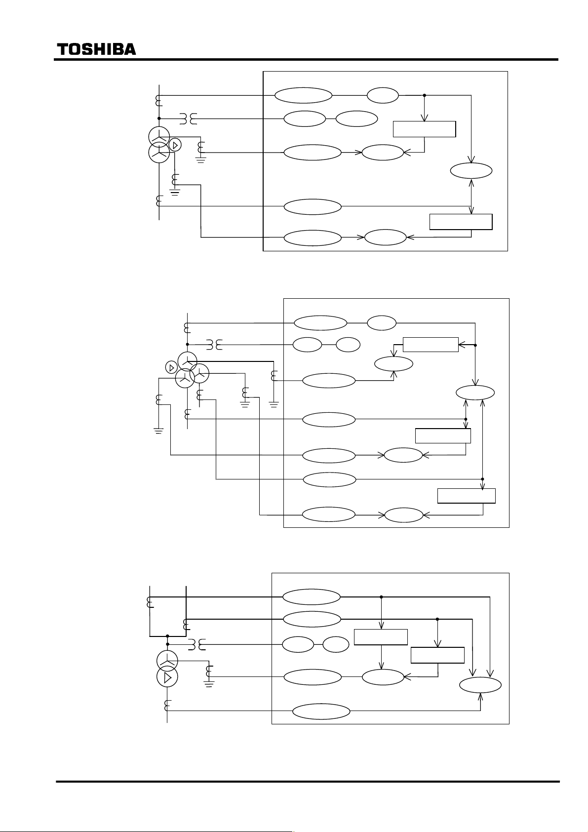
6 F 2 S 0 8 5 7
1CT
HV
LV
2CT
2nCT
HV
MV
GRT100
1OC/1OCI THR
VT
FRQ V/F
Calculate 3I0
1nCT
2nCT
1EF/1EFI
2OC/2OCI
2EF/2EFI
1REF
2REF
Figure 2.1.1 Measuring Elements of Model 100 series
GRT100
1CT
VT
LV
3CT
1nCT
3nCT
1OC/1OCI THR
FRQ V/F
1EF/1EFI
Calculate 3I0
1REF
DIFT
Calculate 3I0
DIFT
1CT
HV
LV
3CT
2CT
2OC/2OCI
2EF/2EFI
3OC/3OCI
3EF/3EFI
Figure 2.1.2 Measuring Elements of Model 200 series
GRT100
1OC/1OCI
2CT
VT
1nCT
2OC/2OCI
FRQ V/F
1EF/1EFI
3OC/3OCI
Calculate 3I
1REF
Calculate 3I0
2REF
Calculate 3I0
3REF
0
Calculate 3I0
DIFT
Figure 2.1.3 Measuring Elements of Model 200 series
⎯ 11 ⎯
Page 13
2.2 Current Differential Protection
2.2.1 Differential Scheme
Current differential protection DIFT provides an overall transformer protection deriving phase
current from each transformer winding, calculating the differential current on a per phase basis
and detecting phase-to-phase and phase-to-earth faults.
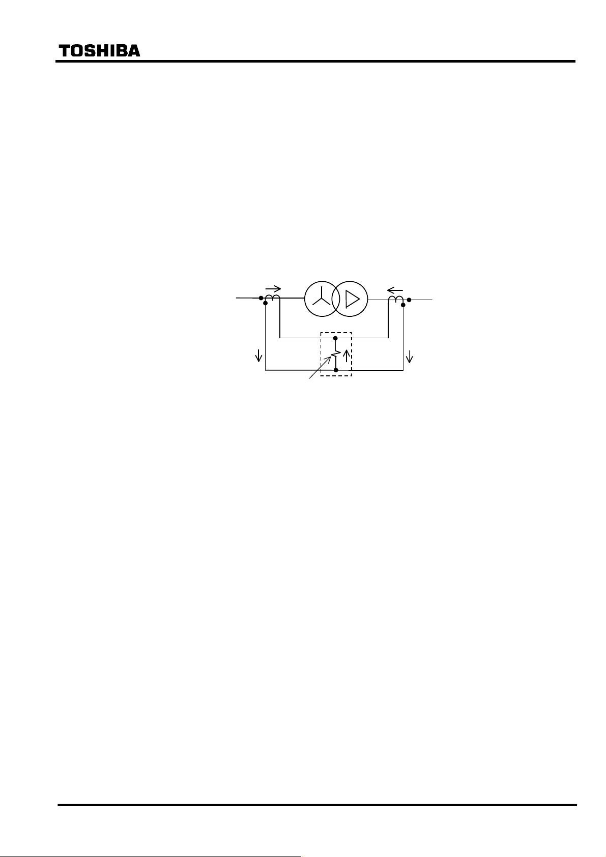
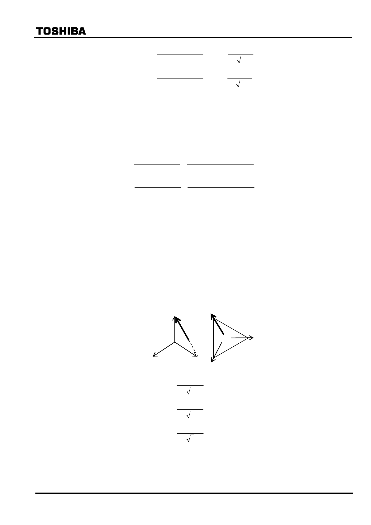
The current differential protection is based on Kirchhoff’s first law that the vector summation of
all currents flowing into a protected zone must be zero. Figure 2.2.1.1 shows the principle of
current differential protection. Differential current (id) is the vector summation of all terminal
current of the transformer. The differential current (id=i1+i2) is zero because the current (i1)
equals current (−i2) during a load condition or an external fault. During an internal fault, the
differential current (id) is not zero because the current (i1) does not equal to the current (−i2), and
the DIFT operates.
I1
Primary
6 F 2 S 0 8 5 7
Secondary
I2
Transformer
i1
id=i1+i2
Differential cu r r ent
detection
Figure 2.2.1.1 Current Differential Protection
DIFT
i2
Scheme logic
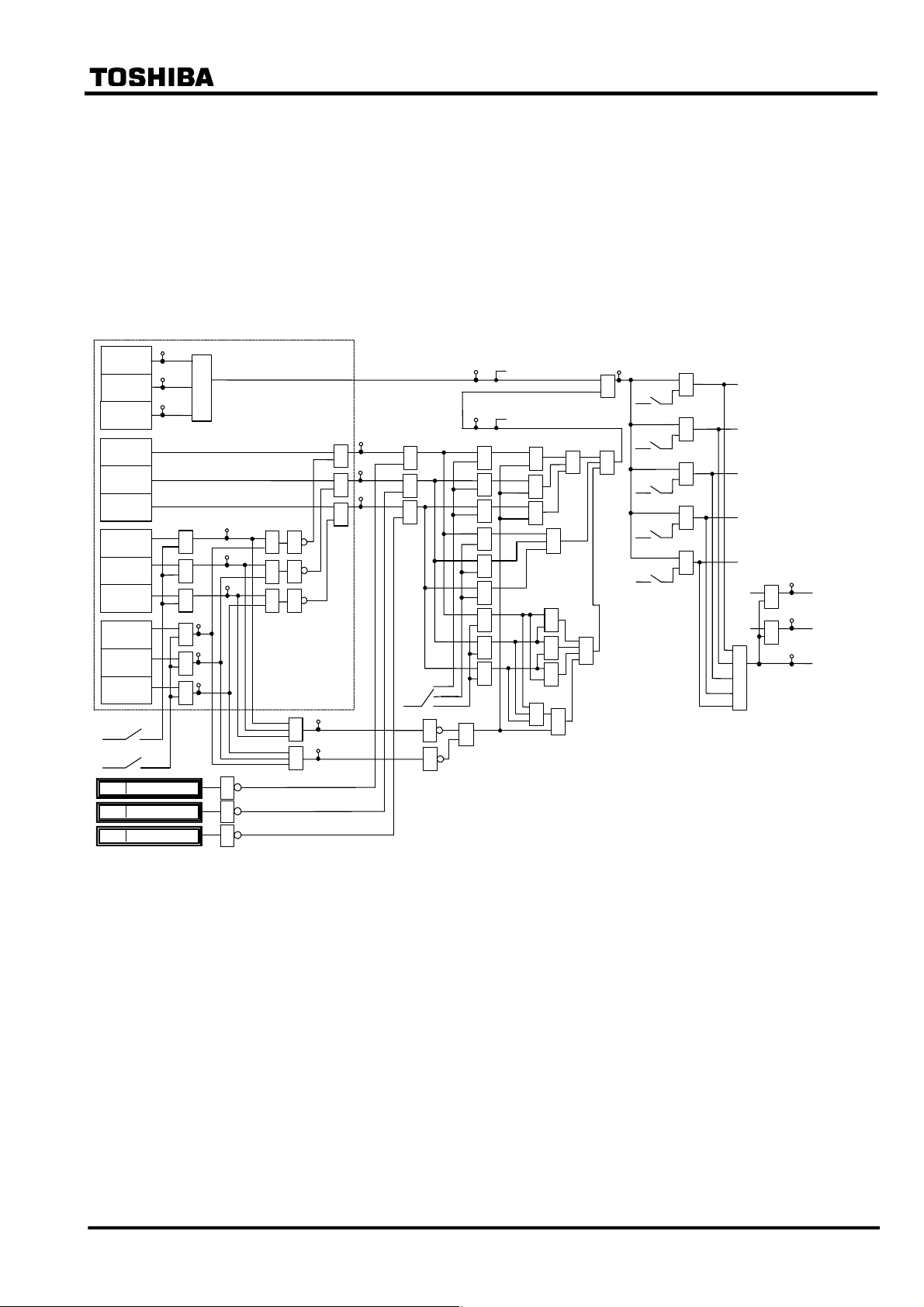
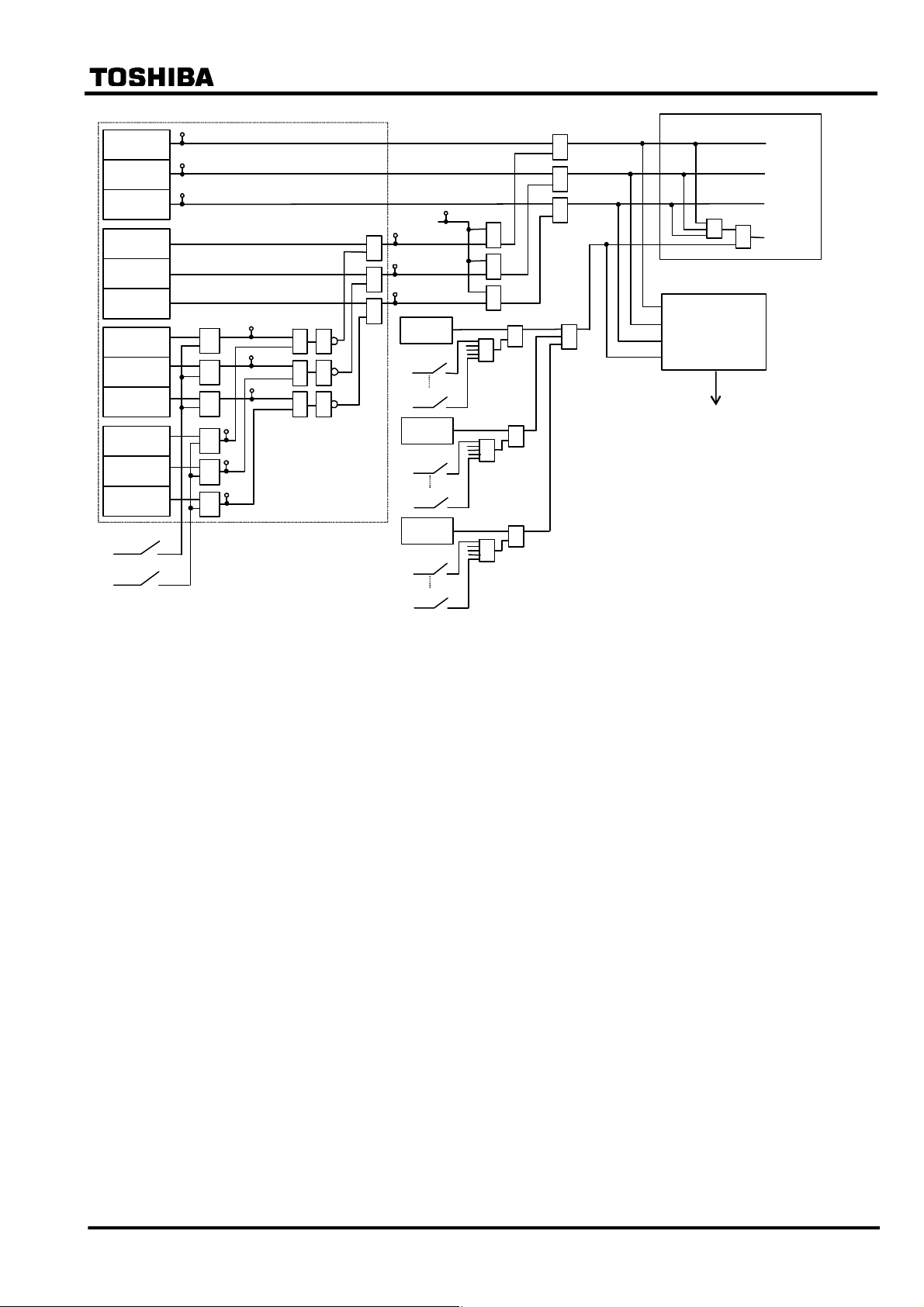
Figure 2.2.1.2 shows the scheme logic of the current differential protection. Current differential
element DIFT comprises sub-elements HOC, DIF, 2F and 5F which operate for differential
current on a per phase basis.
Note: For the symbols used in the scheme logic, see Appendix M.
HOC is a high-set overcurrent element operating for differential current. It provides high-speed
protection for heavy internal faults.
DIF is a percentage restraining element and has dual restraining characteristics, a weak restraint in
the small current region and a strong restraint in the large current region, to cope with erroneous
differential current which may be caused due to output imbalance of the CTs in case of an external
fault. (For the characteristics, see Section 2.10.)
The DIF output signal can be blocked when the 2F or 5F elements detect second harmonic inrush
current during transformer energization or fifth harmonic components during transformer
overexcitation. Blocking is enabled by setting scheme switch [2F-LOCK] or [5F-LOCK] to “ON”.
The following two or three blocking schemes are selectable by scheme switch [DIFTPMD].
“3POR”: When any one phase of the 2F or 5F element operates, tripping by the DIF
element is blocked in all 3 phases. “3POR” is recommended for transformers with
large capacity whose second harmonic component may be low. Its blocking
function is stronger than that of the “1P” or “2PAND” below.
“1P”: When any phase of the 2F or 5F elements operate, only the corresponding phase
output of the DIF element is blocked.
“2PAND”: Even if 2F or 5F element operates during manetising inrush, the trip by DIF
element is allowed when any two phases or more of DIF element operate.
⎯ 12 ⎯
Page 14
DIFT
+
+
1616
1617
1618
HOC-A
HOC-B
HOC-C
DIF-A
DIF-B
DIF-C
2F-A
2F-B
2F-C
5F-A
5F-B
5F-C
2F-Lock
5F-Lock
DIF-A_BLOCK
DIF-B_BLOCK
DIF-C_BLOCK
6 F 2 S 0 8 5 7
“2PAND” is recommended for a transformer with small or midium capacity
whose second harmonic component in inrush current is genarally higher than that
of transformer with large capacity. This mode is applicable if [Phase matching] is
set to “Beta”.
Protection by DIF and HOC can perform instantaneous three-phase tripping of up to five breakers.
Any of the five breaker tripping signals DIFT-1 to DIFT-5 are enabled or disabled by the scheme
switch [DIF1] to [DIF5] settings.
Note: Models 203 and 204 are not provided with DIFT-4 and DIFT-5, and perform tripping of up to
three breakers.
41
42
43
HOC
374
≥1
DIF
121
44
&
&
&
98
99
100
95
96
97
1
1
1
1
≥1
1
≥1
1
≥1
122
≥1
123
≥1 1
&
&
&
&
&
&
45
46
&
&
&
DIFTPMD
+
1
3POR
1P
2PAND (*2)
&
&
&
&
&
&
&
&
&
&
Note:
(*1) Models 203 and 204 are not provided with DIFT-4 and DIFT-5.
(*2) [Phase matching]="Beta" setting only
&
≥1
&
&
≥1
&
&
&
≥1
&
224
≥1
+
+
≥1
+
+
+
≥1
DIF1
DIF2
DIF3
DIF4
DIF5
&
&
&
&
&
TRIP
DIFT-1
DIFT-2
DIFT-3
DIFT-4 (*1)
DIFT-5 (*1)
DIF
HOC
≥1
330
&
331
&
352
DIFT-DIF TP
DIFT-HOC TP
DIFT TRIP
Figure 2.2.1.2 Scheme Logic of Current Differential Protection
⎯ 13 ⎯
Page 15

Display mode following differential tripping
Following a trip output, GRT100 can display either the operating phase or the faulted phase
according to the user’s requirements as shown in Table 2.2.1.1. The operating phase or faulted
phase display is selectable by a setting in the Record menu.
Table 2.2.1.1 Operating Phase / Faulted Phase Display
Operating phase display Faulted phase display
6 F 2 S 0 8 5 7
Setting
(Setting/Record/Fault
record/Phase mode)
Displayed phase Operating phase
Application All two- and three-winding transformers
1 = Operating 2 = Fault
Generally, the operating phase of the DIF element
does not correspond with the faulted phase, but
depends on the transformer configuration and the
electrical quantities that are input to the GRT100
current differential calculation.
Faulted phase (for single-phase to earth, phase to
phase, two-phase to earth and three-phase to
earth faults)
• Faults at primary side or secondary side of Yy0
and Yy6 transformers
• Faults at primary side of Yd1, Yd3, Yd5, Yd7,
Yd9, Yd11, Yy2, Yy4, Yy8 and Yy10
transformers
• Faults at secondary side of Dy1, Dy3, Dy5, Dy7,
Dy9 and Dy11 transformers
• Faults on Dd2, Dd4, Dd6, Dd8 and Dd10
transformers, faults at Zig-zag connected side
of transformers and faults at tertiary side of
three-winding transformers are not supported.
Logic Refer to Figure 2.2.1.4.
∗ Phase (A/B/C) display is based on the operating
signal of DIF or HOC element, and “N” display is
based on the operating signal of REF and DIFT
elements. If the REF is not used, “N” is not
displayed.
Refer to Figure 2.2.1.4.
∗ Phase (A/B/C) display is based on the operating
signal of DIF or HOC element and a differential
current value, and “N” display is based on the
operating signal of REF and DIFT elements. If the
REF is not used, “N” is not displayed.
⎯ 14 ⎯
Page 16
6 F 2 S 0 8 5 7
DIFT
HOC-A
HOC-B
HOC-C
DIF-A
DIF-B
DIF-C
2F-A
2F-B
2F-C
5F-A
5F-B
5F-C
2F-Lock
+
5F-Lock
+
41
42
43
[Op erating phase]
≥1
≥1
121
DIF
44
&
45
&
46
&
98
99
100
95
96
97
≥1
≥1
≥1
1
1
1
&
&
&
&
&
&
1REF
1REF1
+
1REF5
+
2REF
2REF1
+
2REF5
+
3REF
3REF1
+
3REF5
+
&
&
&
≥1
≥1
≥1
≥1
≥1
Fau lt ed phase
& ≥1
&
&
Not e: Mod els 203 and 20 4 are not provided with 1RE F-4,
1REF-5, 2R EF-4, 2REF-5, 3REF-4 and 3REF -5.
selection logic
[Fau lted ph ase]
Phas e A
Phas e B
Phas e C
&
Phas e N
Figure 2.2.1.4 Operating Phase and Faulted Phase Selection Logic
⎯ 15 ⎯
Page 17
6 F 2 S 0 8 5 7
2.2.2 Stability for CT Saturation during Through-fault Conditions
For current differential protection of transformers, GRT100 has a strong restraint characteristic in
the large current region for erroneous differential current due to CT saturation. Further, GRT100
provides a CT saturation countermeasure function. If any CTs saturate due to a large through-fault
current, an apparent differential current is generated in the differential circuit and may cause false
operation of the differential protection.
Operation Principle
Even when a CT saturates under very large primary currents, the waveform of the saturated CT
secondary current has two identifiable periods in each cycle: a non-saturated period and a
saturated period. The GRT100 utilizes this phenomenon and provides very secure operation for
external faults with a large through-fault current.
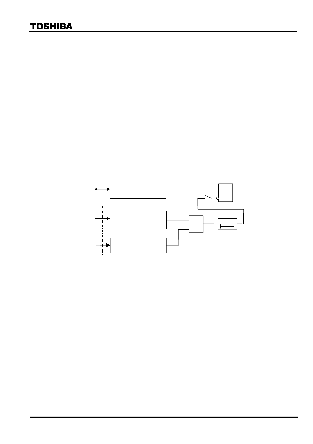
Figure 2.2.2.1 shows a block diagram of the CT saturation countermeasure (CTS). The CTS has a
waveform discriminating element (WDE) and starting element (SE). WDE operates if the change
in the instantaneous value of the differential current is less than a specified percentage of the
change in the instantaneous value of the restraining current. In the CTs non-saturated period, the
differential current is theoretically zero for through-fault currents. The element operates in this
period.
Current
Input
Figure 2.2.2.1 Differential Element with CT Saturation Countermeasure
Differential Element
(DIFT_DIF)
Waveform Discriminating
Element
Starting Element
[CTSEN]
&
ON
&
0
CTS
t
The algorithm of this element is given by the following equation:
ΔId < 0.15×(ΔIp + ΔIn)
where,
ΔId : Change in the differential current Id
(ΔIp + ΔIn) : Change in the restraining current in the positive and negative cycles
Tripping
Output
Id : Differential current
Ip : Sum of positive input currents
In : Sum of negative input currents
SE operates when the sum of the absolute values of the difference between the instantaneous
values of current data at each current input from one cycle is greater than 0.5 × (CT secondary
rated current).
SE discriminates between healthy and faulty power system conditions and blocks the output of
WDE which may otherwise operate during healthy conditions.
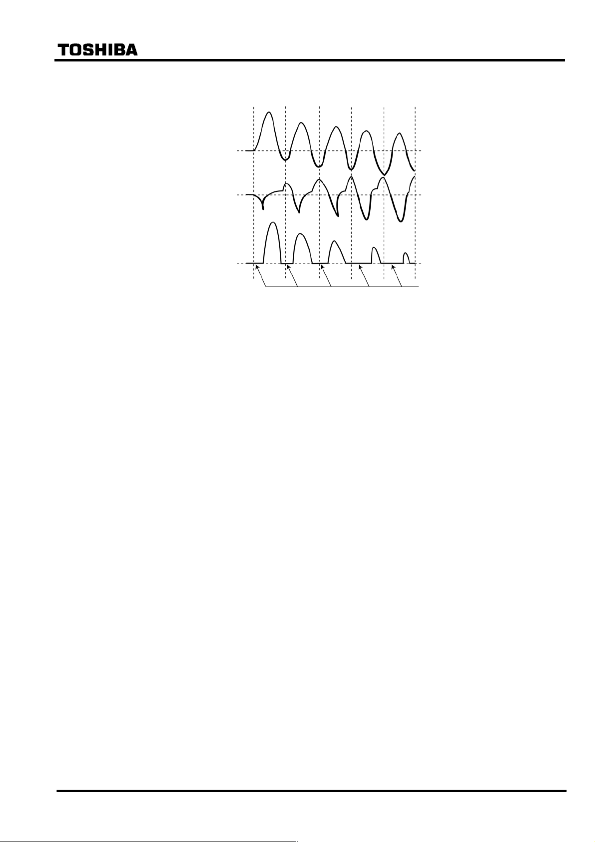
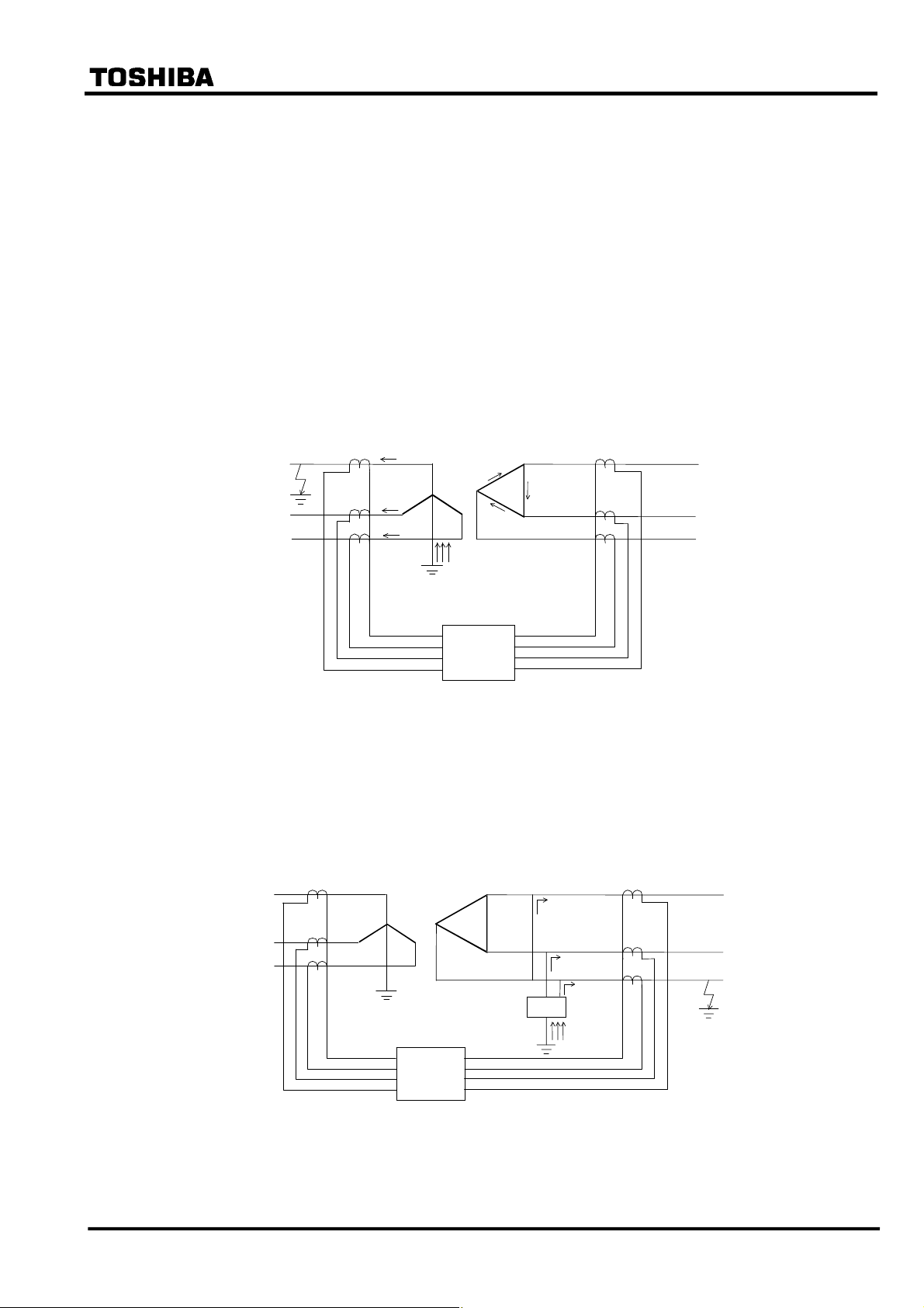
Figure 2.2.2.2 shows CT secondary current waveforms of the incoming and outgoing terminals,
⎯ 16 ⎯
Page 18
6 F 2 S 0 8 5 7
and also the differential current at the time of an external fault with outgoing terminal CT
saturation.
Incoming terminal
current
Outgoing terminal
current
Differential
current
No change period
Figure 2.2.2.2 CT Secondary Current Waveforms and Differential Current for an External
Fault with CT Saturation
From the inception of the fault until the CT secondary current at the outgoing terminal saturates,
the differential current Id is zero and the change in the differential current ΔId obtained from
equation (2) is also zero. However, the change in the restraining current given by equation (3) is a
sufficiently large positive value, so equation (1) is met and WDE operates.
SE detects changes in the terminal currents and rapidly operates, producing an AND output with
WDE. After this, since there is a period during which equation (1) is not satisfied, a certain time
delay is inserted to reliably block the operation of the DIFT_DIF differential element.
If, during an internal fault, there is a period during which the change in the instantaneous value of
the differential current is small due to CT saturation, WDE will not operate because the change in
the restraining current is also small during that period. Thus, during an internal fault, operation of
the differential element is not blocked falsely.
The CTS function can be disabled by the scheme switch [CTSEN].
⎯ 17 ⎯
Page 19
×
6 F 2 S 0 8 5 7
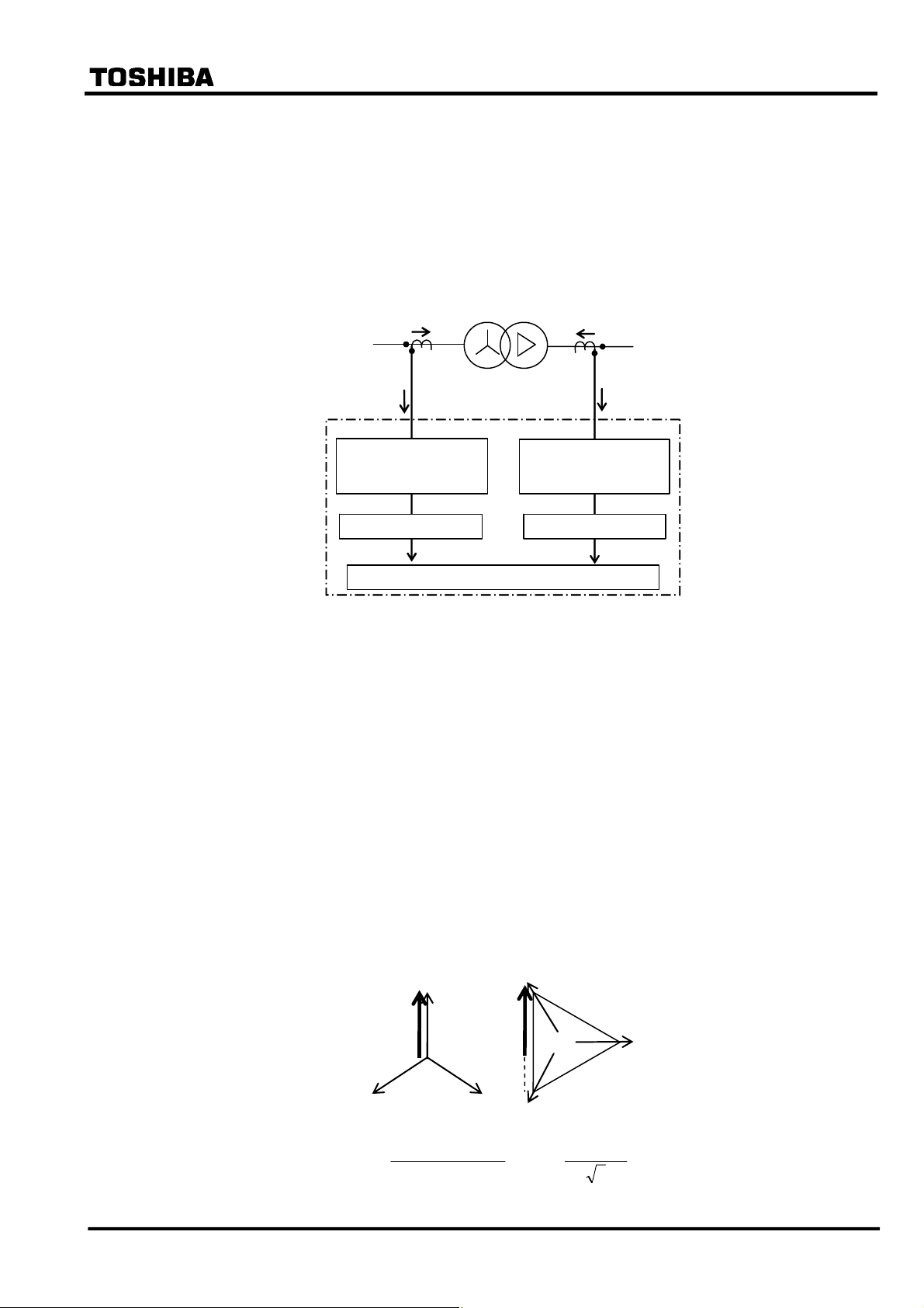
2.2.3 Matching of CT Secondary Currents
The currents supplied to the differential elements must be matched in phase displacement and
amplitude under through-load and through-fault conditions.
Generally, it is difficult to completely match the incoming current with the outgoing current for
the relay input because the CT ratios at the primary, secondary and tertiary sides of a transformer
are not matched in terms of the CT ratio, phase angle and cancelling of zero-sequence current.
GRT100 provides the following matching method:
CT ratio: N1
Ip/N1=i1
GRT100
Matching of phase
angle / Zero-sequence
current elimination
Matching of CT ratio Matching of CT ratio
Primary
Ip
Transformer
i1 Kct2×i2
Kct1
Differential relay calculation
Secondary
Is
CT ratio: N2
Is/N2=i2
Matching of phase
angle / Zero-sequence
current elimination
Figure 2.2.2.1 Matching Method
GRT100 supports selectable two matching methods, α-method (Alpha) and β-method (Beta). The
method is selected by the scheme switch [Phase matching].
Phase matching is performed by setting according to the hands of a clock and the transformer
connections described in IEC60076-1. For details of the setting, refer to 2.2.5.
2.2.3.1 α-method phase matching
This method corrects the phase angle by using each winding current calculated as follows:
- Current substructed zero-sequence current from each phase current in Star- winding side of
transformer
- Phase-to-phase Current in Delta-winding side of transformer
The followings show calculation formula and current vectors in an example of a transformer
Yd11.
Is
1
Isa
Isb
Isc
Ipa
Ip1
Ipb Ipc
2
&
1
pI
=
&&&
pcIpbIpaI
−−
,
&
1
sI
=
3
&&
scIsaI
−
(1)
3
⎯ 18 ⎯
Page 20
6 F 2 S 0 8 5 7
&&&
2
&
=
2
pI
−−
paIpcIpbI
&
,
2
sI
=
3
2
&
3
pI
=
&&&
pbIpaIpcI
−−
,
&
3
sI
=
3
where,
Further, zero-sequence current is eliminated from the relay input current (Ip∗) for the calculation
of the differential current as follows:
&&&
pcIpbIpaI
,, : Primary side terminal current of transformer
&&&
scIsbIsaI
,, : Secondary side terminal current of transformer
&&&
2
&
pI −=
=
1
2
&
pI −=
=
2
2
&
pI −=
=
3
−−
3
=
&&&
−−
=
3
&&&
−−
=
3
3
3
3
&&
saIsbI
−
(2)
3
&&
sbIscI
−
(3)
3
IpcIpbIpaIpapcIpbIpaI
++−
)(3
IpcIpbIpaIpbpaIpcIpbI
++−
)(3
IpcIpbIpaIpapbIpaIpcI
++−
)(3
IpoIpa
IpoIpb
IpoIpc
2.2.3.2 β-method (Traditional method) phase matching
This is a traditional method that delta current (phase-to-phase current) on the Star-winding side of
a Star/Delta transformer and phase current on the Delta-winding side of that is introduced into a
relay input for the calculation of the differential current. Traditionally, the phase matching is
realized by Delta connecting the CTs on the Star-winding side and by Star connecting the CTs on
the Delta-winding side. In GRT100, however, it is realized by software.
The followings show calculation formula and current vectors in an example of a transformer
Yd11.
Ipa
Ip1
I
&
1
pI
Ipb
&&
−
=
pbIpaI
Is1
,
I
Isc
saIsI&&=1
I
(4)
3
&&
pcIpbI
&
2
pI
−
=
,
sbIsI&&=2
(5)
3
&
=
3
pI
⎯ 19 ⎯
&&
−
paIpcI
,
scIsI&&=3
(6)
3
Page 21
6 F 2 S 0 8 5 7
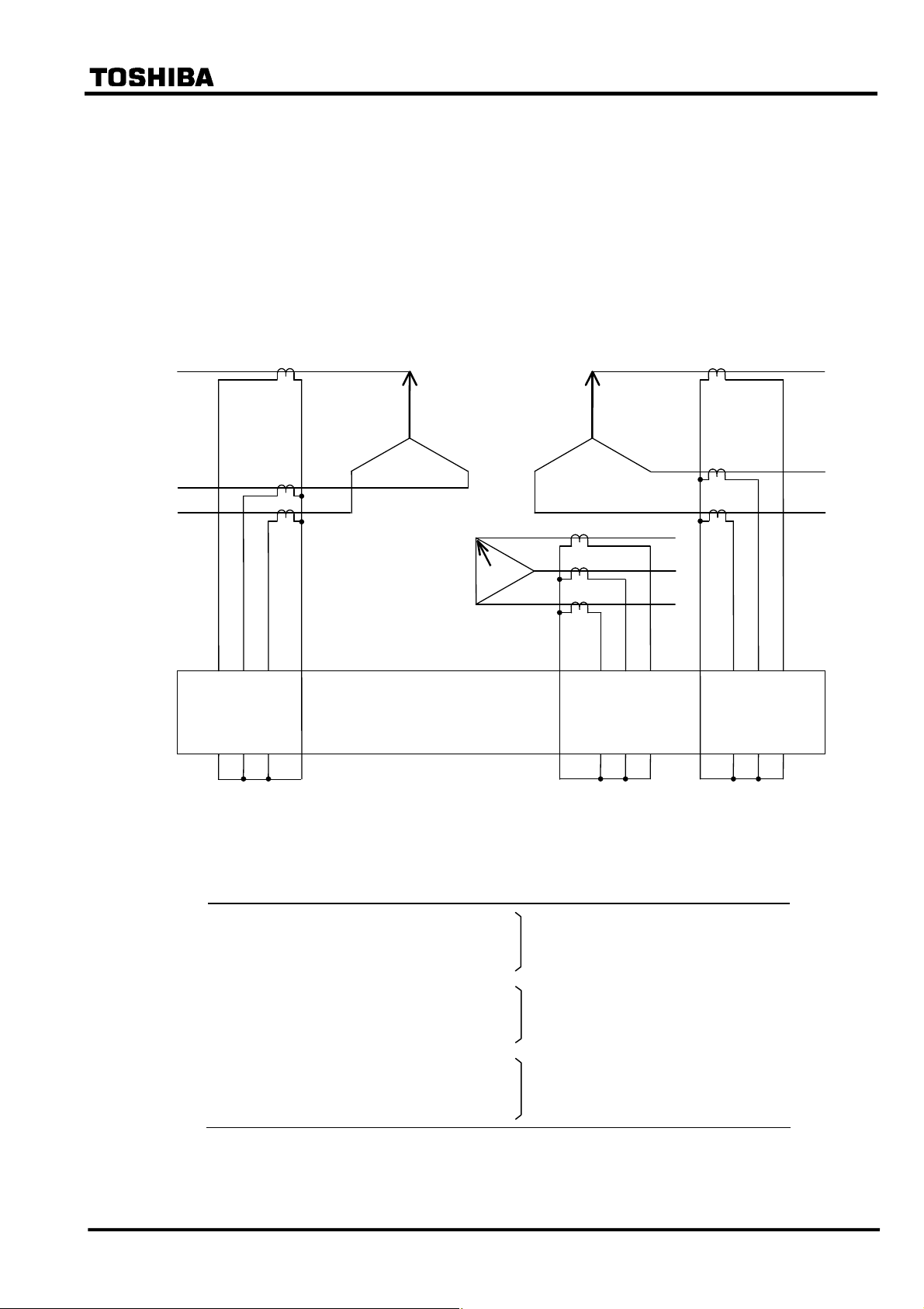
2.2.3.3 Zero-sequence current elimination
In addition to compensating for the phase angle between the primary and secondary currents of the
transforemer, also phase angle matching prevents unnecessary operation due to zero-sequence
current during an external earth fault, such as in the following cases.
Case 1:
When an external fault occurs at the star-connected side of the transformer shown in Figure
2.2.3.2, a zero-sequence current flows in star-connected side, but the zero-sequence current at the
delta-side circulates in the delta winding. The zero-sequence current is only fed into the star
winding side of the DIFT which is star-connected at the CT secondary, thus causing the DIFT to
operate incorrectly. In α-method phase matching, the zero-sequence current is eliminated from a
relay input current as described above. In β-method phase matching, the zero-sequence current is
eliminated from the relay input current by Delta connection on the Star-winding side.
Since the DIFT provides a function to eliminate the zero-sequence current by software, the DIFT
is insensitive the fault described.
I
0
Transforme
I
0
I
0
I
0
I
0
3
0
I
I
0
I
I
DIFT
Figure 2.2.3.2 External Earth Fault at the Star-connected side of a Transformer
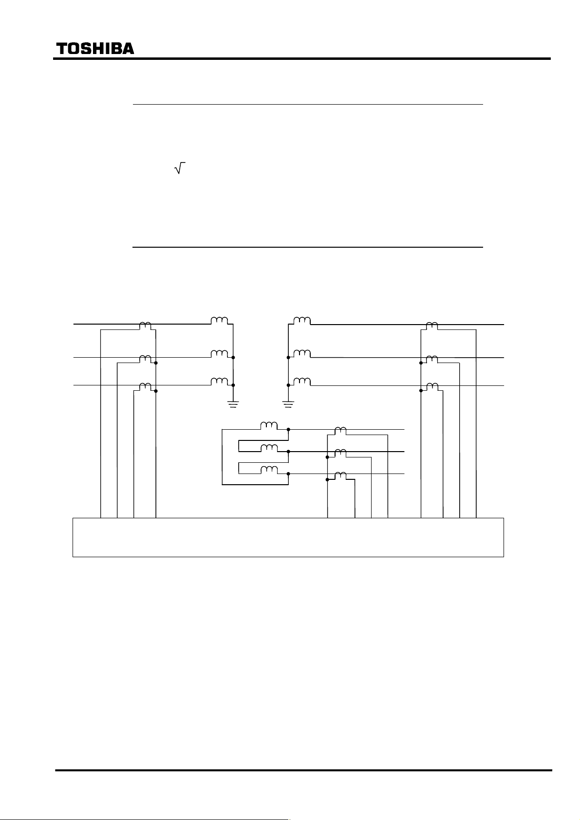
Case 2:
When the delta winding of a power transformer is earthed through an earthing transformer as
shown in Figure 2.2.3.3 and the earthing transformer is located within the differential protection
zone, in case of an external earth fault the zero-sequence current flows only on the delta side of the
power transformer and appears as a differential current.
I
0
I
0
Earthing
Transforme
3I
0
Ia
Ib
Ic
DIF
I
0
Figure 2.2.3.3 External Earth Fault at the Delta-winding side of a Transformer with
in-zone Earthing Transformer
⎯ 20 ⎯
Page 22

6 F 2 S 0 8 5 7
In α-method phase matching, since the DIFT provides a function to eliminate the zero-sequence
current by software, the DIFT is insensitive to the fault described.
In β-method phase matching, however, since the zero-sequence current is not eliminated because
of Star connection on the Delta-winding side, the DIFT may operate unnecessary.
In case the GRT100 is applied to a transformer with in-zone earthing transformer, the [Phase
matching] = “Alpha” setting is recommended.
2.2.3.4 Matching of CT Ratio
If I
to I3 correspond to 1CT to 3CT secondary currents, differential current Id is calculated
1
according to the following equation,
= kct1⋅I1 + kct2⋅I2 + kct3⋅I3
I
d
where kct1 to kct3 are settings corresponding to 1CT to 3CT.
Setting kct1 is obtained by using the following equation.
kct1 = I
= I
n/Ibase1
/( 3 × I
n
) if 1CT is delta-connected.
base1
where
I
= rated secondary current of 1CT (1A or 5A)
n
I
= transformer capacity(kVA)/(
If the 1CT secondary circuit is delta-connected,
= secondary current of 1CT based on the kVA rating of the power transformer.
base1
3 × rated voltage(kV)) × CT ratio of 1CT
3 × I
is used instead of I
base1
above.
Settings kct2 and kct3 are obtained in the same way.
The differential current I
kct1 × I
to kct3 × I3 are equal to the rated secondary current of each CT when the rated line
1
is zero under through-load and through-fault conditions.
d
currents based on the kVA rating of the power transformer flow.
in the equation
base1
⎯ 21 ⎯
Page 23
9
12
22 11
21
6 F 2 S 0 8 5 7
2.2.4 Connection between CT Secondary Circuit and the GRT100
GRT100 is provided with 2 or 3 three-phase current input terminals depending on the relay model.
To validate the phase angle matching described previously and apply in-phase current from each
winding to the relay, connect the CT secondary circuits to the current input terminals of the relay
as follows;
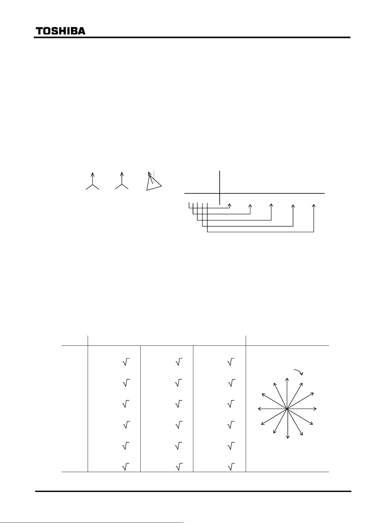
As shown below, the phases used in the phase angle setting (indicated by an arrowhead) must be
connected to the AC input terminals with the lowest number in the terminal group such as 1, 9, 17,
then the other two phases should be connected to the terminals with a larger number clockwise
from the setting phase, such as 3 and 5, 11 and 13, or 19 and 21.
Primary
Tertiary
Secondary
3
1 5
2 4 6
17 19
GRT100
18 10
13
14 20
Figure 2.2.4.1 Connection of CT Secondary Circuit and the GRT100
Terminal numbers and corresponding input currents are shown in the following table.
Model Terminal block Terminal number Input current
100 series / 200 series TB1 1-2
3-4 Current of primary winding
5-6
9-10
11-12 Current of secondary winding
13-14
17-18
19-20 Current of tertiary winding
21-22
⎯ 22 ⎯
Page 24

6 F 2 S 0 8 5 7
2.2.5 Setting
The following shows the setting elements necessary for the current differential protection and their
setting ranges. Setting can be performed on the LCD screen or PC screen.
Element Range Step Default Remarks
DIFT
DIF
ik
0.10 − 1.00
(∗)
0.01 0.30 Minimum operating current
p1
p2
kp
k2f
k5f
HOC kh
CT matching
kct1
CT ratio kct2
kct3
Phase angle matching
yd_p 1(star) / 2(delta) 1 Primary winding
(α-method)
yd_t 1(star) / 2(delta) 1 Tertiary winding
vec_s 0 – 11 1 0 Phase angle difference between primary
vec_t 0 – 11 1 0 Phase angle difference between primary
If [Phase matching]=Alpha setting
yd_s 1(star) / 2(delta) 1 Secondary winding
10 − 100%
10 − 200%
1.00 − 20.00(*)
10 − 50%
10 − 100%
2.00 − 20.00(*)
0.05 − 50.00
0.05 − 50.00
0.05 − 50.00
1% 100% % slope of small current region
1% 200% % slope of large current region
0.01 1.00 Break point of dual characteristics
1% 15% Second harmonic detection
1% 30% Fifth harmonic detection
0.01 2.00 High-set overcurrent protection
0.01 1.00 Primary winding
0.01 1.00 Secondary winding
0.01 1.00 Tertiary winding
and secondary
and tertiary
If [Phase matching]=Beta setting
d1
(β-method)
d3
Scheme switch
[Phase matching] Alpha / Beta Beta Matching methods of CT secondary
[DIFTPMD] 3POR / 1P 3POR Trip mode (if [Phase matching] = Alpha)
[DIFTPMD] 3POR / 2PAND / 1P
[2F – LOCK] Off / On On Block by second harmonic
[5F - LOCK] Off / On On Block by fifth harmonic
[DIF1] to [DIF5] Off / On (**) Output tripping signal
[CTSEN] Off / On Off CT saturation function
(∗): Multiplier of CT secondary rated current including CT ratio correction.
(**): Default settings are dependent on the models. See Appendix H.
d2
0 − 11
0 − 11
0 − 11
1 0 Primary winding
1 0 Secondary winding
1 0 Tertiary winding
currents
3POR Trip mode (if [Phase matching] = Beta)
⎯ 23 ⎯
Page 25

6 F 2 S 0 8 5 7
Setting of ik
ik determines the minimum operation sensitivity of the DIF element. ik is set as a ratio to the CT
secondary rated current.
The minimum sensitivity setting ik is determined from the maximum erroneous differential
current under normal operating conditions.
Setting of p1, p2 and kp
Percentage restraining factor (% slope)
= (Differential current) / (Through current)
= (Differential current) / [{(Incoming current) + (Outgoing current)} /2]
p1 is the percentage restraining factor which defines the DIF restraining characteristic in the small
current region. The setting is determined by the sum of:
• CT accuracy error (generally considered as 5%)
• Tap error: Error between maximum/minimum tap and the middle tap when taking the middle
tap of the tap changer as a reference.
• Matching error: The error due to CT mismatch may be small enough to be neglected in the
setting.
• Relay calculation error, and others (5%)
The recommended setting is “Sum of above” × 1.5 (margin).
p2 is the percentage restraining factor which defines the restraining characteristic in the large
current region. The setting is determined from the maximum erroneous differential current which
is generated when a large through fault current flows.
kp is the break point of the dual percentage restraining characteristics. It is set above the maximum
operating current level of the transformer between the maximum forced-cooled rated current and
the maximum emergency overload current level, as a ratio to the CT secondary rated current.
Setting of k2f
k2f is set to detect the second harmonic content in the inrush current during transformer
energization and blocks GRT100 to prevent incorrect operation due to the inrush current. A
setting of 15% is suggested if there is no data on the minimum second harmonic content.
Setting of k5f
k5f is set to detect the fifth harmonic content during transformer over-excitation and blocks
GRT100 to prevent incorrect operation due to transient over-excitation conditions.
A setting of 30% is suggested if there is no data on the minimum fifth harmonic content.
Setting of k
h
Kh is the HOC setting and should be set above the estimated maximum inrush current.
The recommended setting is more than “Maximum peak value of Inrush current” × kct.
Setting for CT ratio matching
Taking the transformer shown in Figure 2.2.5.1 as an example, the CT ratio matching settings kct1
to kct3
can be calculated as follows. For transformer capacity, take the maximum of the rated
capacites of the three windings.
⎯ 24 ⎯
Page 26
A
6 F 2 S 0 8 5 7
Calculation steps Primary Secondary Tertiary
3
(1) Transformer capacity (kVA)
40 × 10
(2) Voltage(kV) 154 66 11
(3) Rated line current(A) 150 350 2100
=(1)/(
3 × (2))
(4) CT ratio 60 120 240
(5) Secondary rated line current(A) =(3)/(4)
2.50 2.92 8.75
(6) CT secondary rating(A) 5 5 5
(7) Setting =(6)/(5) Kct1=2.00 Kct2=1.71 Kct3=0.57
Note: kct1 to kct3 should be set to 2.00 or less. If more, the CT ratio matching of relay input current
may be not stable.
CT1
300/5
Primary
40MVA
154kV
B
Tertiary
12MVA
11kV
Secondary
40MVA
66kV
CT3
1200/5
CT2
600/5
C
kct1 kct3
GRT100
kct2
Figure 2.2.5.1 CT Ratio Matching
As explained in Section 2.2.3 for Mathcing of CT Secondary Currents, examples of setting for
both α-method and β-method are described as follows:
⎯ 25 ⎯
Page 27
2 3 4
10
6 F 2 S 0 8 5 7
Setting for phase angle matching
The phase angle difference between line currents on either side of the power transformer are
corrected by setting according to the hands of a clock and the transformer connections described in
IEC60076-1 as follows:
(When α-method is selected for [Phase matching])
If a winding is star-connected, set 1 (=star) for winding setting yd_p, yd_s, and yd_t. If
delta-connected, set 2 (=delta). Next, set the phase angle difference vec_s and vec_t from the
primary winding as a lagging angle winding expressed in hours. One hour corresponds to lagging
by thirty degrees.
Note: In the case of a zigzag connected winding, set 2 (=delta).
Example: Setting for star/star/delta transformer.
Primary
Secondary
Tertiary
IEC60076-1
yd_p yd_s vec_s yd_t vec_t
Y y 0 d 11 1 1 0 2 11
Setting
yd_p: Because the primary winding is star-connected, set 1.
yd_s: Because the secondary winding is star-connected, set 1.
vec_s: Because the secondary winding is in phase with the primary winding, set 0.
yd_t: Because the tertiary winding is delta-connected, set 2.
vec_t: Because the tertiary winding lags the primary winding by 330°, set 11.
The settings for the transformer connections described in IEC60076-1 are listed in Table 2.2.5.2.
Note: The following calculation is performed in the relay for phase angle correction.
Table 2.2.5.1 Phase Angle Matching Calculation
O’clock Calculation Remarks
0
1
2
3
4
5
6
7
8
9
10
11
Ia’ = (2Ia − Ib − Ic)/ 3 Ib’ = (2Ib − Ic − Ia)/ 3
Ia’ = (Ia – Ib)/
Ia’ = (Ia − 2Ib + Ic)/ 3 Ib’ = (Ia + Ib − 2Ic)/ 3
Ia’ = (Ic − Ib)/
Ia’ = (2Ic − Ia − Ib)/ 3 Ib’ = (2Ia − Ib − Ic)/ 3
Ia’ = (Ic – Ia)/
Ia’ = (Ib + Ic −2Ia)/ 3 Ib’ = (Ia − 2Ib + Ic)/ 3
Ia’ = (Ib − Ia)/
Ia’ = (2Ib − Ia − Ic)/ 3 Ib’ = (2Ic − Ia − Ib)/ 3
Ia’ = (Ib – Ic)/
Ia’ = (Ia + Ib − 2Ic)/ 3 Ib’ = (Ib + Ic −2Ia)/ 3
Ia’ = (Ia – Ic)/
3 Ib’ = (Ib − Ic)/ 3 Ic’ = (Ic – Ia)/ 3
3 Ib’ = (Ia – Ic)/ 3 Ic’ = (Ib − Ia)/ 3
3 Ib’ = (Ia – Ib)/ 3 Ic’ = (Ib – Ic)/ 3
3 Ib’ = (Ic − Ib)/ 3 Ic’ = (Ia – Ic)/ 3
3 Ib’ = (Ic – Ia)/ 3 Ic’ = (Ia – Ib)/ 3
3 Ib’ = (Ib − Ia)/ 3 Ic’ = (Ic − Ib)/ 3
Ic’ = (2Ic − Ia − Ib)/ 3
Ic’ = (Ib + Ic −2Ia)/ 3
11
Ic’ = (2Ib − Ia − Ic)/ 3
9
Ic’ = (Ia + Ib − 2Ic)/ 3
8
Ic’ = (2Ia − Ib − Ic)/ 3
Ic’ = (Ia − 2Ib + Ic)/ 3
Setting value
0
7
6
1
5
⎯ 26 ⎯
Page 28
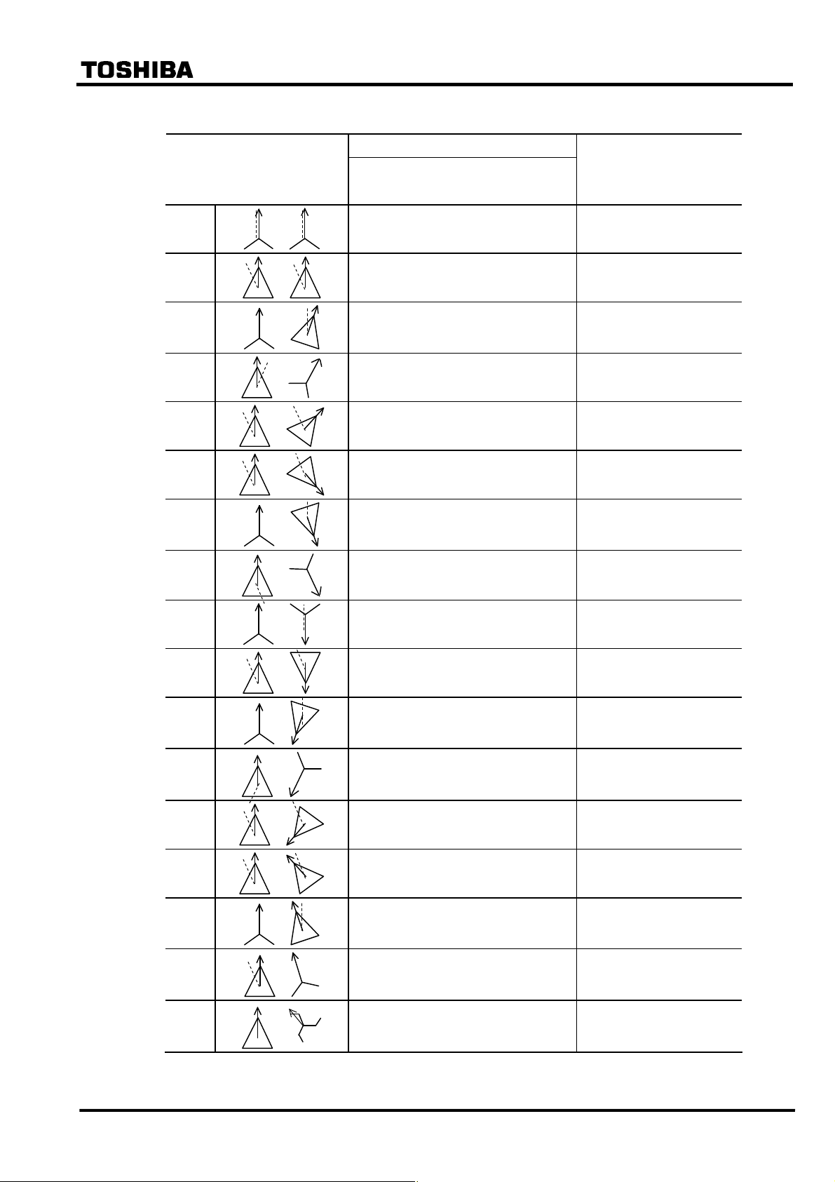
Table 2.2.5.2 Setting for Phase Angle Matching (for α-method)
(a) Settings for typical connections of 2-windings transformer
Transformer connections
described in IEC60076-1
Primary, Secondary
(P) (S)
Yy0
Dd0
Yd1
Dy1
Dd2
Dd4
Yd5
Dy5
Yy6
Dd6
Yd7
Dy7
Dd8
Dd10
Yd11
Dy11
Dz10
Note: A 2-windings transformer covers a 3-windings transformer with a stabilizing-winding circuit
for which 2-windings transformer protection relay can be applied.
Settings for phase angle correction Remarks
Primary, Secondary, Phase angle Diff.
(yd_p) (yd_s) (vec_s)
1 1 0
2 2 0
1 2 1
2 1 1
2 2 2 P: 1 O’clock
2 2 4 P: 1 O’clock
1 2 5 P: 0 O’clock
2 1 5 P: 7 O’clock
1 1 6 P: 0 O’clock
2 2 6 P: 1 O’clock
1 2 7 P: 0 O’clock
2 1 7 P: 5 O’clock
2 2 8 P: 1 O’clock
2 2 10 P: 1 O’clock
1 2 11 P: 0 O’clock
2 1 11
2 2 10 P: 1 O’clock
Phase angle matching
calculation (Table 2.2.5.1)
P: 0 O’clock
S: 0 O’clock
P: 1 O’clock
S: 1 O’clock
P: 0 O’clock
S: 1 O’clock
P: 11 O’clock
S: 0 O’clock
S: 3 O’clock
S: 5 O’clock
S: 5 O’clock
S: 0 O’clock
S: 6 O’clock
S: 7 O’clock
S: 7 O’clock
S: 0 O’clock
S: 9 O’clock
S: 11 O’clock
S: 11 O’clock
P: 1 O’clock
S: 0 O’clock
S: 11 O’clock
6 F 2 S 0 8 5 7
⎯ 27 ⎯
Page 29
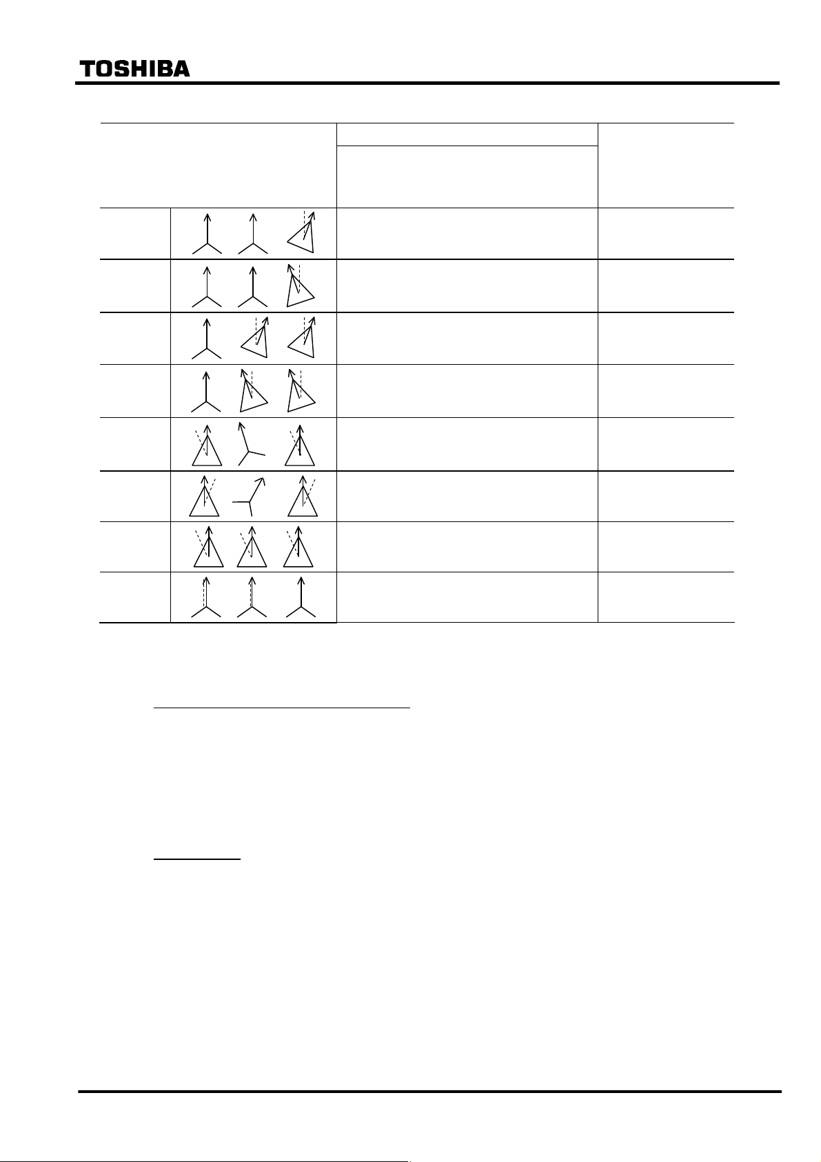
(b) Settings for typical connections of 3-windings transformer
6 F 2 S 0 8 5 7
Transformer connections described in
IEC60076-1
Primary , Secondary,
Tertiary
(P) (S) (T)
Yy0d1
Yy0d11
Yd1d1
Yd11d11
Dy11d0
Dy1d0
Dd0d0
Yy0y0
Settings for phase angle correction
Primary, Secondary, PA Diff., Tertiary, PA Diff.
(yd_p) (yd_s) (vec_s) (yd_t) (vec_t)
1 1 0 2 1
1 1 0 2 11
1 2 1 2 1
1 2 11 2 11
2 1 11 2 0
2 1 1 2 0
2 2 0 2 0
1 1 0 1 0
Remarks
Phase angle matching
calculation (Table
2.2.5.1)
P: 0 O’clock
S: 0 O’clock
T: 1 O’clock
P: 0 O’clock
S: 0 O’clock
T: 11 O’clock
P: 0 O’clock
S: 1 O’clock
T: 1 O’clock
P: 0 O’clock
S: 11 O’clock
T: 11 O’clock
P: 1 O’clock
S: 0 O’clock
T: 1 O’clock
P: 11 O’clock
S: 0 O’clock
T: 11 O’clock
P: 1 O’clock
S: 1 O’clock
T: 1 O’clock
P: 0 O’clock
S: 0 O’clock
T: 0 O’clock
Note: Dotted line: Reference phase
<How to set phase angle matching for GRT100>
Reference phase for phase angle matching
The phase of a star-connected winding side is used as the reference phase for phase angle
matching.
Yd: primary
Dy: secondary
Yy: primary
Dd: the reference vector leads the A phase of the primary side by 30°.
Phase rotation
The relationship between each terminal current vector of a transformer, which depends on the
transformer connection and the connection between the transformer and the power system, must
be checked. The phase displacement of a delta-connected side may not be determined only by the
transformer connection described in IEC60076. Table 2.2.5.3 shows an example illustrating the
connection of a transformer and power system and their current vectors when a Yd1 type
transformer is connected to the power system with both clockwise and anticlockwise phase
rotation. In this case, the setting for phase angle correction is not corresponding to that of Table
2.2.5.1.
⎯ 28 ⎯
Page 30
−
−
−
−
−
−
−
−
−
−
−
6 F 2 S 0 8 5 7
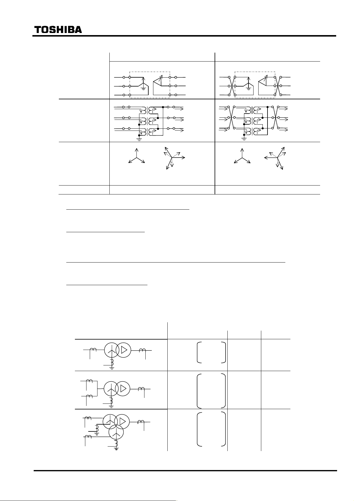
Table 2.2.5.3 Transformer Connection and Current Vector
Connection between
Yd1 Transformer
and Power system
Each winding
connection and
Incoming/Outgoing
current
Incoming current
vector and Outgoing
current vector
Delta-side connected with 30° lagging Delta-side connected with 30° leading
Primary
a
I1a
b
I
1b
c
I
1c
a
b
c
Transformer
U
V
W
Transformer
U
V
W
Yd1
I
2a
I
2b
I
2c
Secondary
u
a
v
b
w
c
u
a
I
2a’=I2a
v
b
I
2b’=I2b
w
c
I
2c’=I2c
Primary
a
I
I
2c
I
2a
I
2b
1a
b
I
1b
c
I
1c
a
b
c
Transformer
U
V
W
Transformer
U
I
1c
V
I
1b
W
I
1a
Yd1
I2c
I
I
2b
2a
Secondary
u
a
v
b
w
c
u
a
I
2a’=I2a
v
b
I
2b’=I2b
w
c
I
2c’=I2c
I
2b
I
2c
I
2a
I
I
1a
I
1c
Incoming
Current
I
1b
I
2a’=I2a
2b’=I2b
I
2b
I
2c
Outgoing
Current
I
2a
I
2c
30
°
I
I
2c’=I2c
2b
I
2a
I
I
1c
Incoming
Current
1a
I
2b’=I2b
I1b
I2b
I
−
2c
I
2a
Outgoing
Current
I
2c’=I2c
I
2c
30°
I
2a’=I2a
I
2a
I
2b
Setting Yd_p=1, yd_s=2, vec_s=1 (Same as Yd1) Yd_p=1, yd_s=2, vec_s=11 (same as Yd11)
Auto-transformer (with internal delta-winding)
Set Yy0.
Zigzag connected transformer
Set yd_p, yd_s and vec_s to 2 (=delta) for zigzag connected side. Zero-sequence current is
canceled.
When three-winding model (model 200 series) applied to two-winding transformer:
Keep the settings of “yd_t” and “vec_t” to the default setting values.
One-and-a-half breaker system
When applied to one-and-a-half breaker system, note the DIFT and REF setting as shown in Table
2.2.5.4.
Table 2.2.5.4 Example of DIFT and REF Setting
Setting
DIFT 1REF 2REF
Yd11
One-and-a-half breaker system
Yd11
Yy0d11
Yd11 yd_p=1
yd_s=2
vec_s=11
Yy0d11
yd_p=1
yd_s=1
vec_s=0
yd_t=2
vec_s=11
Yy0d11
yd_p=1
yd_s=1
vec_s=0
yd_t=2
vec_s=11
1I0 --
2Io --
1I0 1I0
⎯ 29 ⎯
Page 31

6 F 2 S 0 8 5 7
(When β-method is selected for [Phase matching])
The phase angle differences between line currents on each side of the power transformer are
corrected by setting according to the hands of a clock as follows:
Rule 1:
If all the windings are star-connected, then take one of the windings as a reference winding and set
1 (= one o’clock) for it. For other winding(s), set the phase angle difference from the reference
winding by the expression of the leading angle. One hour corresponds to leading by thirty degrees.
Example 1 If the setting winding leads the reference winding by 60°, set 3 (= three o’clock).
Example 2 If the setting winding is in phase with the reference winding, set 1 (= one
o’clock).
Example 3 If the setting winding lags the reference winding by 60° (that is leading by 300°),
set 11 (= eleven o’clock).
Rule 2:
If any of the windings are delta-connected, take one of the delta-connected winding(s) as a
reference winding and set 0 (= noon) for it. For other star- or delta-connected winding(s), set
according to the Rule 1 mentioned above.
Example 1 If the setting winding leads the reference winding by 60°, set 2 (= two o’clock).
Example 2 If the setting winding is in phase with the reference winding, set 0 (= noon).
Example 3 If the setting winding lags the reference winding by 60° (that is leading by 300°),
set 10 (ten o’clock).
The settings for the two-winding transformer connections described in IEC60076-1 are listed in
Table 2.2.5.5.
Three-winding transformers are also set according to the above mentioned rules.
Example 4 Setting for star/star/delta transformer.
Setting (d1 / d2 / d3)
Primary (d1) 11
Primary
Secondary
Tertiary
Secondary (d2) 11
Tertiary (d3) 0
⎯ 30 ⎯
Page 32

1
6 7 8 9 10 11 Ia
Note: The following calculation is performed in the relay for phase angle correction.
Setting Calculation Remarks
0 Ia = Ia
1
2
3
4 Ia = Ib
5
6
7
8 Ia = Ic
9
10
11
Ia = (Ia – Ic)/
Ia = −Ic
Ia = (−Ic + Ib)/
Ia = (Ib – Ia)/
Ia = −Ia
Ia = (−Ia + Ic)/
Ia = (Ic – Ib)/
Ia = −Ib
Ia = (Ia – Ib)/
3
3
3
3
3
3
Setting value
0
2
3
4
5
6 F 2 S 0 8 5 7
⎯ 31 ⎯
Page 33

Table 2.2.5.5 Setting for Phase Angle Matching (for β-method)
(a) Settings for typical connections of 2-windings transformer
Transformer connections
described in IEC60076-1
Settings for phase angle correction Remarks
Primary , Secondary
6 F 2 S 0 8 5 7
(d1) (d2)
Yy0
1 , 1
Dd0
Yd1
Dy1
Dd2
Dd4
Yd5
Dy5
Yy6
0 , 0
1 , 0
0 , 11
0 , 10
or 2 , 0
0 , 8
or 4 , 0
5 , 0
0 , 7
1 , 7
Based on primary winding.
Based on secondary winding.
Based on primary winding.
Based on secondary winding.
Based on primary winding.
Dd6
Yd7
Dy7
Dd8
Dd10
Yd11
Dy11
Note: A 2-windings transformer covers a 3-windings transformer with a stabilizing-winding circuit
or 7 , 1
0 , 6
or 6 , 0
7 , 0
0 , 5
0 , 4
or 8 , 0
0 , 2
or 10 , 0
11 , 0
0 , 1
Based on secondary winding.
Based on primary winding.
Based on secondary winding.
Based on primary winding.
Based on secondary winding.
for which 2-windings transformer protection relay can be applied.
⎯ 32 ⎯
Page 34

(b) Settings for typical connections of 3-windings transformer
6 F 2 S 0 8 5 7
Transformer connections described in
IEC60076-1
Yy0d1
Yy0d11
Yd1d1
Yd11d11
Dy11d0
Dy1d0
Dd0d0
Yy0y0
Settings for phase angle correction
Primary, Secondary, Tertiary
(d1) (d2) (d3)
1 , 1 , 0
11 , 11 , 0
1 , 0 , 0
11 , 0 , 0
0 , 1 , 0
0 , 11 , 0
0 , 0 , 0
1 , 1 , 1
Remarks
Note :
1. If all the windings are star-connected, then take one of the windings as a reference winding
and set 1 (= one hour) for it.
2. If any of the windings are delta-connected, take one of the delta-connected winding(s) as a
reference winding and set 0 for it.
⎯ 33 ⎯
Page 35

2.3 Restricted Earth Fault Protection
Restricted earth fault protection (REF) is a zero-phase current differential scheme applied to a
star-connected winding whose neutral is earthed directly or through a low impedance. It gives
highly sensitive protection for internal earth faults.
REF employs a low impedance current differential scheme which detects the differential current
between the zero-sequence current I
current I
in the neutral conductor as shown in Figure 2.3.1.
N
Figure 2.3.1 Restricted Earth Fault Protection
6 F 2 S 0 8 5 7
derived from the three-phase line currents and the neutral
0
Ia+Ib+Ic
REF
I
N
REF and the overall differential protection DIFT use the three-phase line currents in common.
GRT100 has two or three REF elements depending on the model, providing separate protection
for all star-connected and neutral-earthed windings.
The elements have the same percentage restraining characteristics and are stable for all faults
outside the protected zone.
Figure 2.3.2 shows the block diagram of the REF element which is composed of REF_DIF and
REF_DEF. The REF_DIF has a percentage restraining characteristic while the REF_DEF
provides a directional check feature to discriminate between internal and external faults. When the
REF_DEF is “ON”, the REF_DEF element is used. The REF_DEF element provides additional
security against incorrect operation of the REF element in the event of saturation of the neutral
CT. The REF_DEF is blocked when the maximum phase current exceeds 2 × kct × (Rated current
of neutral CT), since the REF element is used for earth fault protection of transformer winding.
For details, see Section 2.10.3. In case of terminal current larger than that, the DIFT element
provides tripping. The REF_DEF can be disabled by setting the scheme switch [REF_DEF] to
“OFF”.
REF_DIF
REF_DEF
internal fau lt d e tec t ion
Ires≦ 2.0× Max_kct
&
≥1
&
REF
[REF_DEF]
+
ON
OFF
Figure 2.3.2 Block Diagram of REF
Figure 2.3.3 shows the scheme logic of the restricted earth fault protection when three REF
elements are applied. Each REF element can perform instantaneous or time-delayed tripping of up
to five breakers. Any of the five breaker tripping signals 1REF-1 to 3REF-5 are enabled or
disabled by the scheme switch [1REF1] to [3REF5] settings.
Note: Models 203 and 204 are not provided with 1REF-4, 1REF5, 2REF-4, 2REF-5, 3REF-4 and
⎯ 34 ⎯
Page 36

[
]
[
]
[
]
[
]
[
]
6 F 2 S 0 8 5 7
3REF-5.
1REF
2REF
T1REF
71
74
t 0
0.00 - 10.00s
Same as above
+
+
+
+
+
1REF1
“ON”
1REF2
“ON”
1REF3
“ON”
1REF4
“ON”
1REF5
“ON”
&
&
&
&
&
1REF-1
1REF-2
1REF-3
1REF-4
1REF-5
≥1
2REF-1
2REF-2
2REF-3
2REF-4
2REF-5
≥1
332
1REF TRIP
333
2REF TRIP
≥1
3REF-1
3REF-2
3REF-3
3REF-4
3REF-5
334
3REF TRIP
3REF
77
Same as above
Note: Models 203 and 204 are not provided with 1REF-4, 1REF-5, 2REF-4, 2REF-5, 3REF-4 and
3REF-5.
Figure 2.3.3 Scheme Logic of Restricted Earth Fault Protection
Appendix L shows applications of the three REF elements to various types of transformers. When
protecting a two- or three-winding transformer, 1REF, 2REF and 3REF elements should be
applied to the primary (or high-voltage) winding, secondary (or medium-voltage) winding and
tertiary (or low-voltage) winding respectively. This is also valid for auto-transformer protection
but the application must comply with Appendix L.
In the application to auto-transformers, one REF element may introduce two or three line currents
and one neutral current as shown in Appendix L. 1REF to 3REF elements recognize the number of
the line currents according to the scheme switch setting of [1REF] to [3REF].
⎯ 35 ⎯
Page 37

6 F 2 S 0 8 5 7
Setting
The following shows the setting elements for the restricted earth fault protection and their setting
ranges.
Element Range Step Default Remarks
1REF 1ik
1kct1
1kct2
1kct3
1p2
1kp
2REF 2ik
2kct1
2kct2
2kct3
2p2
2kp
3REF 3ik
3kct1
3kct2
0.05 − 0.50(*)
1.00 − 50.00
1.00 − 50.00
1.00 − 50.00
50 − 100%
0.50 − 2.00(*)
0.05 − 0.50(*)
1.00 − 50.00
1.00 − 50.00
1.00 − 50.00
50 − 100%
0.50 − 2.00(*)
0.05 − 0.50(*)
1.00 − 50.00
1.00 − 50.00
0.01 0.50 Minimum operating current
0.01 1.00
0.01 1.00 CT ratio matching
0.01 1.00
1% 100% % slope of DF2
0.01 1.00 DF2 restraining current section of
large current characteristic
0.01 0.50 Minimum operating current
0.01 1.00
0.01 1.00 CT ratio matching
0.01 1.00
1% 100% % slope of DF2
0.01 1.00 DF2 restraining current section of
large current characteristic
0.01 0.50 Minimum operating current
0.01 1.00
0.01 1.00 CT ratio matching
3kct3
3p2
3kp
T1REF
T2REF
T3REF
Scheme switch
[1REF1] to [1REF5]
[2REF1] to [2REF5]
[3REF1] to [3REF5]
[1REF] to [3REF]
[REF_DEF]
(*): Multiplier of secondary rated current
(**): Default settings are dependent on the models. See Appendix H.
1.00 − 50.00
50 − 100%
0.50 − 2.00(*)
0.00 − 10.00s
0.00 − 10.00s
0.00 − 10.00s
Off/On
Off/On
Off/On
1Io/2Io/3Io
Off/On
0.01 1.00
1% 100% % slope of DF2
0.01 1.00 DF2 restraining current section of
large current characteristic
0.01s 0.00s
0.01s 0.00s Delayed tripping
0.01s 0.00s
(**)
(**)
(**)
1Io
Off
Enable or disable to output
tripping signal
Number of line currents input to
1REF, 2REF and 3REF elements
Setting of ik (1ik, 2ik and 3ik)
1ik, 2ik and 3ik are minimum operating current settings and are set as a ratio to the line CT
secondary rated current. ik is determined from the maximum erroneous zero sequence differential
current under normal operating conditions. A typical setting would be between 10% and 50%.
⎯ 36 ⎯
Page 38

6 F 2 S 0 8 5 7
Setting of kct (1kct1-1kct3, 2kct1-2kct3 and 3kct1-3kct3)
CT ratio matching is performed between the line CT(s) and the neutral CT by setting 1kct1-1kct3
for 1REF element, 2kct1-2kct3 for 2REF element and 3kct1-3kct3 for 3REF element. The settings
are obtained as a ratio of the line CTs ratio to the neutral CT ratio and the line CTs have the
notations shown in Appendix L according to 1REF to 3REF applications.
For example, the settings of 1kct1, 1kct2, 2kct1 and 2kct2 are calculated;
1kct1 = (CT ratio of line CT 1ct-1)/(CT ratio of neutral CT 1nCT)
1kct2 = (CT ratio of line CT 1ct-2)/(CT ratio of neutral CT 1nCT)
2kct1 = (CT ratio of line CT 2ct-1)/(CT ratio of neutral CT 2nCT)
2kct2 = (CT ratio of line CT 2ct-2)/(CT ratio of neutral CT 2nCT)
where,
CT ratio = (primary rated current)/(secondary rated current).
Setting of scheme switch [1REF] to [3REF]
[1REF] to [3REF] are set to "1I0", "2I0" or "3I0" when they introduce one, two or three line
currents respectively.
Setting of scheme switch [REF_DEF]
The function of REF_DEF is set to “On/Off” by setting.
⎯ 37 ⎯
Page 39

2.4 Overcurrent Protection
GRT100 provides definite time and inverse time overcurrent elements for both phase faults and
earth faults, separately for each transformer winding. Three phase currents from each set of line
CTs are used for the phase fault protection elements, while the earth fault protection is based on
the neutral CT input.These elements can be used selectively depending on the requirements of the
particular application, but the following points should be noted:
• In the case of large power transformers, overcurrent protection is usually employed only as
back-up protection for terminal faults, and for uncleared LV system faults. In such cases, the
overcurrent elements can be applied either on one or both sides of the transformer as
required.
• Coverage of internal transformer faults is generally limited.
• It is common practice to apply IDMTL phase and earth fault overcurrent protection as
back-up for the LV system. Current and time settings must be arranged to grade with
downstream relays and fuses. The phase fault current setting must also be set to exceed the
maximum overload current.
• High-set instantaneous overcurrent protection can be applied on the primary side to provide
back-up protection for terminal faults. The current setting must be higher than the maximum
through-fault current to ensure that the element does not operate for faults on the LV side.
6 F 2 S 0 8 5 7
One of the following IEC-standard-compliant inverse time characteristics or one long time inverse
characteristic is available for the inverse current protection.
• standard inverse IEC 60255-3
• very inverse IEC 60255-3
• extremely inverse IEC 60255-3
Up to three definite time elements (1OC to 3OC) and inverse time elements (1OCI to 3OCI) input
three phase currents from line CTs in the transformer windings.
Up to three definite time elements (1EF to 3EF) and inverse time elements (1EFI to 3EFI) input
neutral currents from CTs in the neutral circuit.
Figure 2.4.1 and Figure 2.4.2 show the scheme logic of overcurrent protection. Each element can
perform time-delayed tripping of up to five breakers. The breaker tripping signals are blocked by
the scheme switch settings.
The number of overcurrent elements applied depends on the relay models.
⎯ 38 ⎯
Page 40

[
]
+
[
]
+
[
]
+
[
]
+
[
]
+
[
]
+
[
]
+
[
]
+
[
]
+
[
]
+
6 F 2 S 0 8 5 7
1OC
1OCI
A
B
C
A
B
C
47
48
49
50
51
52
≥1
≥1
370
0.00 - 10.00s
225
T1OC
t 0
1OC1
1OC2
1OC3
1OC4
1OC5
1OCI1
&
&
&
&
&
&
1OC-1
1OC-2
1OC-3
1OC-4
1OC-5
≥1
1OCI-1
335
1OC TRIP
&
1OCI2
&
1OCI3
&
1OCI4
&
1OCI5
Note: 2OC and 3OC provide the same logic as 1OC. 2OCI and 3OCI provide the same logic as 1OCI.
Models 203 and 204 are not provided with 1OC-4, 1OC-5, 2OC-4, 2OC-5, 3OC-4, 3OC-5,
1OCI-4, 1OCI-5, 2OCI-4, 2OCI-5, 3OCI-4 and 3OCI-5.
1OCI-2
1OCI-3
1OCI-4
1OCI-5
≥1
339
1OIC TRIP
Figure 2.4.1 Scheme Logic of the Overcurrent Protection
⎯ 39 ⎯
Page 41

[
]
+
[
]
+
[
]
+
[
]
+
[
]
+
[
]
+
[
]
+
[
]
+
[
]
+
[
]
+
6 F 2 S 0 8 5 7
1EF
1EFI
72
73
T1EF
t 0
0.00 - 10.00s
1EF1
1EF2
1EF3
1EF4
1EF5
1EFI1
&
&
&
&
&
&
≥1
1EF-1
1EF-2
1EF-3
1EF-4
1EF-5
343
1EFI-1
1EF TRIP
&
1EFI2
&
1EFI3
&
1EFI4
&
1EFI5
Note: 2EF and 3EF provide the same logic as 1EF. 2EFI and 3EFI provide the same logic as 1EFI.
Models 203 and 204 are not provided with 1EF-4, 1EF-5, 2EF-4, 2EF-5, 3EF-4, 3EF-5, 1EFI-4,
1EFI-5, 2EFI-4, 2EFI-5, 3EFI-4 and 3EFI-5.
1EFI-3
1EFI-4
1EFI-5
≥1
1EFI-2
346
1EFI TRIP
Figure 2.4.2 Scheme Logic of the Overcurrent Protection for Earth Faults
⎯ 40 ⎯
Page 42

6 F 2 S 0 8 5 7
Setting
The following shows the setting elements for the overcurrent protection and their setting ranges.
Element Range Step Default Remarks
1OC
2OC
3OC
T1OC
T2OC
T3OC
1OCI
2OCI
3OCI
T1OCI
T2OCI
T3OCI
1EF
2EF
3EF
T1EF
0.10 − 20.0(*)
0.10 − 20.0(*)
0.10 − 20.0(*)
0.00 − 10.00s
0.00 − 10.00s
0.00 − 10.00s
0.10 − 5.00(*)
0.10 − 5.00(*)
0.10 − 5.00(*)
0.05 − 1.00
0.05 − 1.00
0.05 − 1.00
0.10 − 20.00(*)
0.10 − 20.00(*)
0.10 − 20.00(*)
0.00 − 10.00s
0.01 2.00 Definite time overcurrent (line)
0.01 2.00 Definite time overcurrent (line)
0.01 2.00 Definite time overcurrent (line)
0.01s 1.00s Delayed tripping for 1OC
0.01s 1.00s Delayed tripping for 2OC
0.01s 1.00s Delayed tripping for 3OC
0.01 1.00 Inverse time overcurrent (line)
0.01 1.00 Inverse time overcurrent (line)
0.01 1.00 Inverse time overcurrent (line)
0.01 1.00 Time multiplier setting for 1OCI
0.01 1.00 Time multiplier setting for 2OCI
0.01 1.00 Time multiplier setting for 3OCI
0.01 2.00 Definite time overcurrent (neutral)
0.01 2.00 Definite time overcurrent (neutral)
0.01 2.00 Definite time overcurrent (neutral)
0.01s 1.00s Delayed tripping for 1EF
T2EF
T3EF
1EFI
2EFI
3EFI
T1EFI
T2EFI
T3EFI
Scheme switch
M1OCI to M3OCI
M1EFI to M3EFI
Scheme switch
[1OC1] to [3OC5]
[1OCI1] to [3OCI5]
[1EF1] to [3EF5]
[1EFI1] to [3EFI5]
0.00 − 10.00s
0.00 − 10.00s
0.10 − 5.00(*)
0.10 − 5.00(*)
0.10 − 5.00(*)
0.05 − 1.00
0.05 − 1.00
0.05 − 1.00
Long-Std-Very-Ext
Long-Std-Very-Ext
Off/On (**) Enable or disable tripping by
0.01s 1.00s Delayed tripping for 2EF
0.01s 1.00s Delayed tripping for 3EF
0.01 1.00 Inverse time overcurrent (neutral)
0.01 1.00 Inverse time overcurrent (neutral)
0.01 1.00 Inverse time overcurrent (neutral)
0.01 1.00 Time multiplier setting for 1EFI
0.01 1.00 Time multiplier setting for 2EFI
0.01 1.00 Time multiplier setting for 3EFI
Std
Std
Inverse time characteristic selection of
OCI elements
EFI elements
OC elements
OCI elements
EF elements
EFI elements
(*) : Multiplier of CT secondary rated current.
(**) : Default settings are dependent on the models. See Appendix H.
The overcurrent elements use the same three-phase line currents and neutral current as the
⎯ 41 ⎯
Page 43

6 F 2 S 0 8 5 7
differential protection and the restricted earth fault protection. When choosing settings, the
following relationships between the overcurrent elements and the connected windings must be
taken into account.
1OC, 1OCI : Primary (high-voltage) winding
2OC, 2OCI : Secondary (medium-voltage) winding
3OC, 3OCI : Tertiary (low-voltage) winding
1EF, 1EFI : 1REF applied neutral circuit
2EF, 2EFI : 2REF applied neutral circuit
3EF, 3EFI : 3REF applied neutral circuit
⎯ 42 ⎯
Page 44

+
[
]
+
[THR2]
+
+
[THR4]
+
+
[
]
2.5 Thermal Overload Protection
The thermal overload protection is applied to protect transformers from electrical thermal damage.
A-phase current is used to detect the thermal overload of a transformer. The characteristics are
exponential functions according to the IEC 60255-8 standard and take into account the I
due to the particular operational current and the simultaneous cooling due to the coolant. In this
way the tripping time during an overload condition takes the pre-load into consideration. An alarm
stage can be set to operate before reaching the tripping condition.
Figure 2.5.1 shows the scheme logic of the thermal overcurrent protection. THR tripping output
can be given to up to five breakers. Any of the five breaker tripping signals THR-1 to THR-5 can
be blocked by the scheme switch [THR1] to [THR5] settings. Alarming signal THR-A can be
blocked by the scheme switch [THRA] setting.
THR
83
S
87
A
THR1
“ON”
6 F 2 S 0 8 5 7
2
R losses
&
&
THR-1
THR-2
“ON”
[THR3]
“ON”
“ON”
[THR5]
“ON”
THRA
“ON”
Note: Models 203 and 204 are not provided with THR- 4 and THR-5.
&
&
&
248
THR-3
THR-4
THR-5 &
THR-A
≥1
351
THR TRIP
Figure 2.5.1 Scheme Logic of Thermal Overload Protection
Setting
The following shows the setting elements for the thermal overload protection and their setting
ranges.
Element Range Step Default Remarks
τ 0.5 − 500.0min
k
IB
0.10 − 4.00
0.50 − 2.50(*1)
0.1min 60.0min Thermal time constant
0.01 1.30 Constant
0.01 1.00 Basic current
Ip
TA
Scheme switch
THR1 to THR5
THRA
0.00 − 1.00(*1)
0 − 10min
Off/On
Off/On
0.01 0.00 Pre-specified load current
1min 10min Time for alarm (before trip) (*3)
(*2)
On
Enable or disable
Trip
Alarm
(∗1): Multiplier of CT secondary rated current
(*2): Default settings are dependent on the models. See Appendix H.
(*3): Alarming time = THR trip time (operating time) – TA (setting time)
Note: Ip sets a minimum level of previous load current to be used by the thermal element, and is
typically used when testing the element. For the majority of applications, Ip should be set to
zero, in which case the previous load current, Ip, is calculated internally by the thermal
model, providing memory of conditions occurring before an overload.
⎯ 43 ⎯
Page 45

[
[
]
[
[
]
[
]
[
]
[
]
[
]
[
2.6 Frequency Protection
GRT100 provides underfrequency or overfrequency protection and/or alarms for load shedding or
for detecting such an overfrequency condition caused by disconnecting load from a particular
generation location.
The frequency element FRQ comprises two frequency elements 81-1 and 81-2, the former is used
for tripping and the latter for alarms.
Figure 2.6.1 shows the scheme logic of the frequency protection. The tripping element 81-1
outputs underfrequency and overfrequency trip signals L1 and H1. Either underfrequency or
overfrequency protection is selected by setting the scheme switch [FRQ-UF1] to “ON” or “OFF”.
The alarm element 81-2 outputs underfrequency and overfrequency alarm signals L2 and H2.
Either underfrequency or overfrequency alarms are selected by setting the scheme switch
[FRQ-UF2] to “ON” or “OFF”.
Frequency protection can perform time-delayed tripping of up to five breakers. Any of the breaker
tripping signals FRQ-1 to FRQ-5 can be blocked by the scheme switch [FRQ1] to [FRQ5]
settings.
Note: Models 203 and 204 are not provided with FRQ-4 and FRQ-5.
6 F 2 S 0 8 5 7
81-1
81-2
UV
[FRQ-UF1]
+
FRQ-UF2]
+
Alarm signal FRQ-A can be blocked by the scheme switch [FRQA] setting.
Frequency protection is blocked under the condition that the system voltage is lower than the
setting of the undervoltage element UV.
TFRQL
0 t
L1
L2
H1
H2
119
1
ON
ON
89
90
91
92
&
&
&
1
&
1
0.00 - 60.00s
TFRQH
0 t
0.00 - 60.00s
TFRQA
≥1
0.00 - 60.00s
≥1
0t
+
+
+
+
+
+
FRQ1
FRQ2
FRQ3
FRQ4
FRQ5
FRQA
&
&
&
&
&
&
FRQ-1
FRQ-2
FRQ-3
FRQ-4
FRQ-5
FRQ-UF1]
+
≥1
FRQ-UF2]
+
ON
OFF
ON
OFF
353
FRQ-UF TRIP
&
354
FRQ-OF TRIP
&
249
FRQ TRIP
355
FRQ-UF ALARM
&
356
FRQ-OF ALARM
&
257
FRQ A
Note: Models 203 and 204 are not provided with FRQ-4 and FRQ-5.
Figure 2.6.1 Scheme Logic of Frequency Protection
⎯ 44 ⎯
Page 46

6 F 2 S 0 8 5 7
Setting
The following shows the setting elements for the frequency protection and their setting ranges.
Element Range Step Default Remarks
81-1 (L1, H1)
81-2 (L2, H2)
UV
TFRQL
TFRQH
TFRQA
Scheme switch
[FRQ-UF1]
[FRQ-UF2]
[FRQ1] to [FRQ5]
[FRQA]
(*) : Frequency values shown in parentheses are for the case of 60Hz rating. Other frequency values
are shown for the case of 50Hz rating.
(**): Default settings are dependent on the models. See Appendix H.
45.00 − 55.00Hz
(54.00 − 66.00Hz
45.00 − 55.00Hz
(54.00 − 66.00Hz
40 − 100V
0.00 − 60.00s
0.00 − 60.00s
0.00 − 60.00s
Off/On
Off/On
Off/On
Off/On
0.01Hz
0.01Hz
0.01Hz
0.01Hz
1V 40V Undervoltage block
0.01s 10.00s Underfrequency trip time
0.01s 10.00s Overfrequency trip time
0.01s 10.00s Alarm time delay
49.00Hz
59.00Hz) (*)
48.00Hz
58.00Hz)
On
On
(**)
On
Trip
Alarms
delay
delay
Enable or disable
Trip
Alarm
Trip
Alarm
⎯ 45 ⎯
Page 47

2.7 Overexcitation Protection
Overexcitation protection is applied to protect transformers from overvoltage and overfluxing
conditions.
Any single phase-to-phase connected voltage is used to detect overexcitation. Trip and alarm
characteristics, which are based on a measurement of the voltage/frequency ratio, are provided.
Figure 2.7.1 shows the scheme logic of overexcitation protection. Overexcitation element V/F
responds to voltage/frequency and outputs three signals. Signal T has an inverse time
characteristic. Signals H and A have high-set and low-set definite time characteristics
respectively. Signal T and signal H with a delayed pick-up timer TVFH are used for tripping.
Signal A is used for alarm with a delayed pick-up timer TVFA.
The V/F element has a reset feature with definite time reset. The reset time RT is set to match the
cooling characteristic that is the time for the protected transformer to reach a normal temperature
after releasing the overexitation condition.
6 F 2 S 0 8 5 7
V/F
H
T
A
81
80
82
TVFH
t
1 - 600s
TVFA
t
1 - 600s
V/F-T
≥1
TV/F-H
0
0
[V/F1]
+
[V/F2]
+
[V/F3]
+
[V/F4]
+
[V/F5]
+
[V/FA]
+
&
&
&
&
&
&
242
V/F-1
V/F-2
V/F-3
V/F-4
V/F-5
≥1
V/F-A
V/F-T
TV/F-H
&
&
362
363
350
V/F-L TRIP
V/F-H TRIP
V/F TP
Note: Models 203 and 204 are not provided with V/F-4 and V/F-5.
Figure 2.7.1 Scheme Logic of Overexcitation Protection
Overexcitation protection can trip up to five breakers. Any of the breaker tripping signals V/F-1 to
V/F-5 can be blocked by the scheme switch [V/F1] to [V/F5] settings.
Note: Models 203 and 204 are not provided with V/F-4 and V/F-5.
Alarm signal V/F-A can be blocked by the scheme switch [V/FA] setting.
⎯ 46 ⎯
Page 48

A
(p
)
A
6 F 2 S 0 8 5 7
Setting
The following shows the setting elements for the overexcitation protection and their setting
ranges.
Element Range Step Default Remarks
V
A
L
H
LT
HT
RT
TVFH
TVFA
Scheme switch
[V/F1] to [V/F5]
[V/FA]
(∗): Multiplier of (rated voltage) / (rated frequency)
(**): Refer to Appendix H for default setting.
100.0 − 120.0V
1.03 − 1.30
1.05 − 1.30
1.10 − 1.40
1 − 600s
1 − 600s
60 − 3600s
1 − 600s
1 − 600s
Off/On
Off/On
0.1V 100.0V Transformer rated voltage / VT ratio
(∗)
0.01 1.03 Alarm
0.01 1.05 Low level
0.01 1.40 High level
1s 600s Operation time at low level
1s 1s Operation time at high level
1s 250s Reset time after removing
1s 10s Operating time at high level setting
1s 10s Alarm time
(**)
On
(Inverse time curve)
(Inverse time curve)
overexcitation condition
(Definite time delay)
(Definite time delay)
Enable or disable tripping
Enable or disable alarm
V/Hz
H
: Alarm level
H: High level (definite time tripping)
L: Low level
HT: Operating time at high level
L T: Operating time at low level
TVFH: Operating time at high level setting
TVFA : Alar m time
Withstand curve for transformer overexcitation
ick up level
L
0
TVFA
TVFH
HT
LT
Figure 2.7.2 Setting Points
sec
(log T)
⎯ 47 ⎯
Page 49

2.8 Trip by External Devices
Up to four binary signals EXT. MECHANICAL TRIP1 to EXT. MECHANICAL TRIP4 can be
used for tripping external devices. Figure 2.8.1 shows the scheme logic for the signal
EXT_MEC.TP1. The signal can trip up to five breakers. Any of the tripping signals
EXT_MEC.TP1-1 to EXT_MEC.TP4-5 can be blocked by the scheme switches [M.T1-1] to
[M.T1-5] setting.
Note: Models 203 and 204 are not provided with EXT_MEC.TP1-4 and EXT_MEC.TP1-5, and
[M.T1-4] and [M.T1-5].
The other binary signals have the same scheme logic.
6 F 2 S 0 8 5 7
EXT. MECHANICAL TRIP1
1536
[M.T1-1]
+
[M.T1-2]
+
[M.T1-3]
+
[M.T1-4]
+
[M.T1-5]
+
&
&
&
&
&
EXT_MEC.TP1-1
EXT_MEC.TP1-2
EXT_MEC.TP1-3
EXT_MEC.TP1-4
EXT_MEC.TP1-5
357
≥1
MEC.TRIP1
Figure 2.8.1 Scheme Logic of Trip by External Device
Setting
The following shows the setting elements for tripping by external devices and their setting ranges.
Element Range Step Default Remarks
Scheme switch
EXT_MEC.TP1-1 to -5
EXT_MEC.TP2-1 to -5
Off/On
(*)
Enable or disable tripping
EXT_MEC.TP3-1 to -5
EXT_MEC.TP4-1 to -5
(*): Default settings are dependent on the model. See Appendix H.
⎯ 48 ⎯
Page 50

2.9 Tripping Output
Figure 2.9.1 shows the tripping logic. Each protection can output five tripping signals to enable
tripping for five breakers. The tripping signals are set according to the number of breakers to be
tripped and drive the heavy duty, high-speed tripping output relays TRIP-1 to TRIP-5.
Note: Models 203 and 204 are not provided with TRIP-4 and TRIP-5.
When the scheme switch [L/O] is set to “ON”, tripping signals can be locked and reset with the
〔RESET〕key on the front panel. When the switch is set to “OFF”, they are reset automatically
after clearing the fault.
The tripping output relays reset 200ms after the tripping signal disappears. When [L/O] is set to
“OFF”, the tripping circuit must be opened with the auxiliary contact of the breaker prior to reset
of the tripping relay to prevent the tripping relay from directly interrupting the tripping current of
the breaker.
6 F 2 S 0 8 5 7
⎯ 49 ⎯
Page 51

TRIP-1
DIFT-1
1OC-1
1OCI-1
1REF-1
1EF-1
1EFI-1
2OC-1
2OCI-1
2REF-1
2EF-1
2EFI-1
3OC-1
3OCI-1
3REF-1
3EF-1
3EFI-1
≥1
≥1
≥1
≥1
+
[L/O]
“ON”
≥1
[RESET]
6 F 2 S 0 8 5 7
Tripping output
relay
&
1
&
≥1
Q
S
F/F
R
≥1
0 t
0.2s
284
TRIP-1
FRQ-1
V/F-1
THR-1
MECHANICAL TRIP1-1
MECHANICAL TRIP2-1
MECHANICAL TRIP3-1
MECHANICAL TRIP4-1
TRIP-2
Same as TRIP-1
TRIP-3
Same as TRIP-1
TRIP-4
Same as TRIP-1
TRIP-5
Same as TRIP-1
≥1
≥1
0 t
0.2s
0 t
0.2s
0 t
0.2s
t
0
0.2s
291
298
305
312
TRIP-2
TRIP-3
TRIP-4
TRIP-5
Figure 2.9.1 Tripping Logic
⎯ 50 ⎯
Page 52

2.10 Characteristics of Measuring Elements
2.10.1 Percentage Current Differential Element DIF
The segregated-phase current differential element DIF has dual percentage restraining
characteristics. Figure 2.10.1 shows the characteristics of DF1 and DF2 on the differential current
(Id) and restraining current (Ir) plane. Id is a vector summation of phase current of all windings
and Ir is a scalar summation of phase current of all windings.
6 F 2 S 0 8 5 7
Id
ik
ik
2
Figure 2.10.1 Current Differential Element
DF1
kp
Id = 2Ir (one-end infeed)
DF2
Characteristic DF1 is expressed by the following equation:
Id ≥ p1 x Ir + (1 −p1/2)ik
where,
p1 : slope of DF1
Ir
ik : minimum operating current
Id and Ir are defined as follows for a three-winding transformer.
= | kct1⋅I1 + kct2⋅I2 + kct3⋅I3 |
I
d
=(kct1⋅|I1 |+ kct2⋅|I2 |+ kct3⋅|I3 |)/2
I
r
where,
kct1 ,kct2 ,kct3
I
,I2 ,I3 : currents of primary, secondary and tertiary winding
1
: CT ratio matching settings of primary, secondary and tertiary winding
This characteristic has weaker restraint in the small current region and ensures sensitivity to low
level faults.
Characteristic DF2 is expressed by the following equation:
Id ≥ p2 x Ir + (p1 −p2)kp + (1 −p1/2)ik
where,
p2 : slope of DF2
kp : break point of DF1 characteristic
This characteristic has stronger restraint in the large current region and ensures stability against
CT saturation during through faults.
⎯ 51 ⎯
Page 53

6 F 2 S 0 8 5 7
2.10.2 High-set Overcurrent Element HOC
High-set overcurrent element HOC is an instantaneous overcurrent characteristic, and is applied in
the differential circuit. The characteristic is expressed by the following equation:
Id ≥ kh
Id is defined as follows for three-winding transformer.
= | kct1⋅I1 + kct2⋅I2 + kct3⋅I3 |
I
d
where,
kct1, kct2, kct3: CT ratio matching settings of primary, secondary and tertiary winding
HOC is an un-restrained current differential element which can protect a transformer against
damage due to a heavy internal fault, because it has a simple operation principle and high-speed
operation. Note that HOC is not immune to transformer inrush currents and therefore cannot be
applied with a sensitive setting.
2.10.3 Restricted Earth Fault Element REF
The restricted earth fault element REF is composed of REF_DIF and REF_DEF, as was shown in
Figure 2.3.2.
The REF_DIF has dual percentage restraining characteristics. Figure 2.10.2 shows the
characteristics on the differential current (Id) and restraining current (Ir) plane. Id is the
differential current between the residual current of each winding and the neutral current and Ir is
the restraining current which is the larger of the residual current and the neutral current.
Id
DF2
max-kct⋅ik
max-kct⋅ik
Figure 2.10.2 REF_DIF Characteristic
DF1
kp
Ir
Characteristic DF1 is expressed by the following equation:
≥ p1⋅Ir + (1-p1) ⋅ik⋅max-kct
I
d
where,
p1 : slope of DF1 (fixed to 10%)
ik : minimum operating current
max-kct : CT ratio matching of line CT to neutral CT (when plural line CTs are applied,
maximum kct is employed.)
For the 1REF element, I
and Ir are calculated by the following equations when applied to a circuit
d
with one neutral CT and three line CTs. (For the REF element application, see Appendix L.)
= |1kct1⋅I1o + 1kct2⋅I2o + 1kct3⋅I3o + IN |
I
d
⎯ 52 ⎯
Page 54

6 F 2 S 0 8 5 7
Ir = max.( 1kct1⋅|I1a| , 1kct1⋅|I1b| , 1kct1⋅|I1c| , 1kct2⋅|I2a| , 1kct2⋅|I2b| , 1kct2⋅|I2c| ,1kct3⋅|I3a| ,
1kct3⋅|I
| , 1kct3⋅|I3c| , |IN| )
3b
where,
I
I
I
,I2o ,I
1o
,I1b ,I1c ,I2a ,I2b ,I2c ,I3a ,I3b ,I
1a
: residual current of neutral circuit
N
: residual current of primary, secondary and tertiary winding
3o
: phase current of primary, secondary and tertiary winding
3c
1kct1, 1kct2, 1kct3: CT ratio matching of primary, secondary and tertiary line CT to neutral
CT
Characteristic DF2 is expressed by the following equation:
I
≥ p2 (Ir−kp)
d
where
p2 : slope of DF2
kp : break point of DF1 characteristic
The characteristic of REF_DEF is composed of a directional characteristic and a non-directional
characteristic as shown in Figure 2.10.3 (a) and (b). This characteristic is employed so that the
REF is not blocked at one-end infeed current I
90°
(*1)
3I
0
.
N
180
°
Ik1, ik2: Current sensitivity (0.01pu, 0.025pu fixed)
I
: Neutral current of transformer
N
3I
: Zero sequence current (calculated from Ia, Ib, Ic)
0
*1: MAX(Ia,Ib,Ic) ≤ 2×MAX(kct1,kct2,kct3)
0
Ik1
Operating
270°
0°
I
N
Ik2
3I
0
(a) (b)
Figure 2.10.3 REF_DEF Characteristic
The REF_DEF detects an internal fault by checking the direction between transformer neutral
current I
and zero-sequence current 3I0 calculated from phase currents Ia, Ib and Ic. The REF_DEF
N
is blocked when the maximum phase current is larger than 2 times of Max-kct as follows:
Max.(1kct1•I
, ….1kct3•I3c) ≥ I
1a
=Max.(1kct1,1kct2,1kct3)×2
BLK
⎯ 53 ⎯
Page 55

y
6 F 2 S 0 8 5 7
(Example)
Primary
CT ratio: 2400/1
kct1=2
I01
1REF
Secondar
CT ratio: 3600/1
CT ratio:
1200/1
I
N
kct2=3
I
02
max-kct = 3
Therefore, REF is blocked at
I
=3×2.0=6A (CT secondary)
BLK
If the maximum of phase
currents of both primary and
secondary windings is 7200A
(=6x1200A), the REF is blocked.
Reference current: 1200A
(Rated current of neutral CT)
2.10.4 Inverse Time Overcurrent Element OCI and EFI
The OCI and EFI elements have one long time inverse characteristic and three inverse time
characteristics in conformity with IEC 60255-3 as shown in Figure 2.10.4. One of these
characteristics can be selected.
These characteristics are expressed by the following equations and curves.
(s)
200
T=1.0
Long Time Inverse
t = T
×
(I/Is)−1
120
Standard Inverse
t = T
×
(I/Is)
0.02
− 1
0.14
Very Inverse
×
(I/Is)
13.5
− 1
t = T
Extremely Inverse
×
(I/Is)
80
2
− 1
t = T
where,
t : operating time
I : fault current
Is : current setting
T : time multiplier setting
Operating
time
100
50
20
10
0.5
0.2
Long-time Inverse
5
2
1
Standard Inverse
Very Inverse
Extremely Invease
0.1
1
2
Current I (Multiple of setting current)
5 10 20 30
Figure 2.10.4 Characteristics of Inverse Time Overcurrent Element
⎯ 54 ⎯
Page 56

6 F 2 S 0 8 5 7
2.10.5 Definite Time Overcurrent element OC and EF
The OC and EF elements measure the phase currents and the residual current respectively.
2.10.6 Thermal Overload Element THR
Thermal overload element THR has a characteristic based on thermal replica according to the IEC
60255-8 standard (see Appendix N), which evaluates the phase current (A-phase) of the CT
secondary circuits. Figure 2.10.5 shows the characteristic of THR element. The element has trip
and alarm stages.
Trip stage:
2
2
I
t = τ x Ln
Alarm stage:
t = τ x Ln
where
− Ip
I2 − (k x IB)
2
(I
− Ip2) x (1 − TA/τ)
2
I
− (k x IB)
2
2
t : operating time
τ : thermal time constant
I : load current
kxIB : allowable overload current as specified in IEC 60255-8 (refer to Appendix N)
IB : basic current of transformer (rated current)
k : constant (allowable overload current / IB)
Ip : prior load current before the overload occurs
TA : time for alarm
(Alarming time = t (operating time) – T
A (setting time)
Ln : natural logarithm
Figure 2.10.6 shows the thermal curve for a range of time constant settings in the cold state when
the prior load current Ip is zero.
⎯ 55 ⎯
Page 57

A
6 F 2 S 0 8 5 7
t
T
A
larm
Trip
T
A
0
K ⋅ I
B
I
Figure 2.10.5 Characteristic of Thermal Overload Element
Thermal Curves (Cold Curve - no
prior load)
10000
1000
100
τ
10
500
B
100
50
20
10
5
2
1
)
Operate Time (minutes)
0.01
1
0.1
110
Overload Current (Multiple of kI
Figure 2.10.6 Thermal Curves
⎯ 56 ⎯
Page 58

A
(
)
A
6 F 2 S 0 8 5 7
2.10.7 Frequency Element FRQ
GRT100 has two elements for trip or alarm. Each element operates either in overfrequency or
underfrequency.
2.10.8 Overexcitation Element V/F
The characteristic is based on the ratio of voltage to frequency. The alarm is definite time
delayed, while the tripping characteristic is either definite time or inverse time, as shown in
Figure 2.10.7.
: Alarm level
H: High level (definite time tripping)
V/Hz
H
L
0
TVFA
Figure 2.10.7 Characteristic of Overexcitation Element
TVFH
HT
L: Low level
HT: Operating time at high level
LT: Operating time at low level
TVFH: Operating time at high level setting
TVFA : Alar m time
LT
pick up level
sec
(log T)
The inverse time characteristic of V/F is expressed by the following equation.
K
2
t =
(V/F) − K
1
where,
t : operating time
V : voltage (any phase-to-phase voltage)
F : frequency
V/F=(Vm/Fm) / (Vs/Fs)
(Vm: Input voltage, Fm: Input frequency, Vs: Setting of rated voltage, Fs: Rated frequency)
(LT) × L − (HT) × H
K
K1=
2
(LT) − (HT)
(LT) × (HT) × (H − L)
=
(LT) − (HT)
The V/F element has a reset feature with definite time reset (RT). When the V/F falls below the
reset threshold, the integral state of the inverse time function is reset to the initial value after the
RT time.
Example: V/F=(Vin/Fin)/(V/Fs)=(130/50)/(100/50)=1.3, in case of Vin: Input voltage (130V),
Fin: Input frequency (50Hz), V: Rated voltage (100V), Fs: Rated frequency (50Hz)
⎯ 57 ⎯
Page 59

3. Technical Description
3.1 Hardware Description
3.1.1 Outline of Hardware Modules
The case outline of GRT100 is shown in Appendix F.
The hardware structures of the models are shown in Figure 3.1.1 and Figure 3.1.2. The front
view shows the equipment without the human machine interface module.
The GRT100 consists of the following hardware modules. The human machine interface module
is provided with the front panel.
• Transformer module (VCT)
• Signal processing module (SPM)
• Binary input and output module #1 (IO1 or IO8)
• Binary input and output module #2 (IO2)
6 F 2 S 0 8 5 7
• Binary output module #3 (IO3)
• Human machine interface module (HMI)
Front view without front panel
SPMIO2VCT
IO1 or
IO8
Figure 3.1.1 Hardware Structure (Model: 101, 201, 203)
⎯ 58 ⎯
Page 60

6 F 2 S 0 8 5 7
Figure 3.1.2 Hardware Structure (Model: 102, 202, 204)
IO3VCT
SPM IO1 or
IO2
IO8
The correspondence between each model and module used is as follows:
Models
Module
VCT
SPM
IO1
IO2
IO3 ×
IO8
HMI
Note: The VCT and SPM modules are not interchangeable among different models.
101 102 201 202 203 204
× × × × × ×
× × × × × ×
× × × ×
× × × × × ×
×
× × × × × ×
×
× ×
The hardware block diagram of the GRT100 using these moduls is shown in Figure 3.1.3.
⎯ 59 ⎯
Page 61

×
A
(*1)
×
×
×
×
A
A
6 F 2 S 0 8 5 7
Binary I/O Module (IO1 or IO8)
I
C input
V
External
clock
Transformer
Module (VCT)
CT × 8
CT × 12
or
or
CT × 15
VT × 1
IRIG-B
port
Signal Processing Module (SPM)
nalogue
filter
Human Machine Interface (HMI)
/D
Converter
MPU1
Opt. I/F
or
Ethernet
LAN I/F
DC/DC
Converter
Binary input
13 or 12
Binary output
(High speed)
5 or 3
Binary I/O Module (IO2)
Binary output
14
Binary input
3
RS485
Transceiver
DC
supply
Trip
command
Remote
Setting and
Monitoring
System
Remote PC
Local
Personal
Computer
Liquid crystal display
40characters×4lines
LEDs
RS232C
I/F
Operation keys
Monitoring jacks
Binary I/O Module (IO3)
Binary output
10
(*1) I03: required for Model 102, 202, 204
Figure 3.1.3 Hardware Block Diagram (Models 101, 102, 201, 202, 203 and 204)
⎯ 60 ⎯
Page 62

6 F 2 S 0 8 5 7
3.1.2 Transformer Module
The transformer module (VCT module) provides isolation between the internal and external
circuits through auxiliary transformers and transforms the magnitude of the AC input signals to
suit the electronic circuits. The AC input signals are as follows:
• three-phase currents (Ia, Ib and Ic) for each winding
• neutral current (IN) for each winding
• phase-to-phase voltage
Figure 3.1.4 shows a block diagram of the transformer module. There are 8 to 12 auxiliary CTs
and 1 auxiliary VT mounted in the transformer module depending on the relay model. (For the
correspondence between the relay model and number of AC input signals, see Table 3.2.1.)
The transformer module is also provided with an IRIG-B port. This port collects the serial
IRIG-B format data from an external clock for synchronization of the relay calendar clock. The
IRIG-B port is isolated from the external circuit by a photo-coupler. A BNC connector is used as
the input connector.
I
a1
I
b1
I
c1
I
N1
I
a2
I
b2
I
c2
I
N2
V
External
clock
BNC connector
IRIG-B port
Signal
processing
module
Figure 3.1.4 Transformer Module (e.g. models 101, 102)
⎯ 61 ⎯
Page 63

(Op
(Op
6 F 2 S 0 8 5 7
3.1.3 Signal Processing Module
The signal processing and communication module (SPM) incorporates a signal processing
circuit and a communication control circuit. Figure 3.1.3.1 shows the block diagram.
The signal processing circuit consists of an analog filter, multiplexer, analog to digital (A/D)
converter, main processing unit (MPU) and memories (RAM and ROM), and executes all kinds
of processing including protection, measurement, recording and display.
The SPM contains a lithium-ion battery, which should be removed at the end-of-life of the
product. The nominal backup time of a lithium-ion battery is one year after the shipment from
the factory.
The analog filter performs low-pass filtering for the corresponding current and voltage signals.
The A/D converter has a resolution of 16 bits and samples input signals at sampling frequencies
of 2400Hz (at 50Hz) and 2880Hz (at 60Hz).
The MPU carries out operations for the measuring elements and scheme logic operations for
protection, recording, displaying and signal transmission control.
The SPM can be provided with Optical interface or Ethernet LAN interface for serial
communication system.
Analog
input
Analog filter
Analog filter
Analog filter
Multiplexer
A/D
converter
MPU
RAM ROM
Optical I/F
tion)
Ethernet LAN
tion)
I/F
Other
modules
Link with Serial
communication
system
Figure 3.1.3.1 Signal Processing Module
⎯ 62 ⎯
Page 64

A
×
6 F 2 S 0 8 5 7
3.1.4 Binary Input and Output Module
There are four types of binary input and output module (IO module): These modules are fitted
according to the model (see Section 3.1.1).
3.1.4.1 IO1 and IO8 Module
IO1 and IO8 provide a DC/DC converter, binary inputs and binary outputs for tripping.
As shown in Figure 3.1.4.1, the IO1 module incorporates a DC/DC converter, 15 photo-coupler
circuits (BI) for binary input signals and 6 auxiliary relays (TP1 to 5) dedicated to the circuit
breaker tripping command.
As shown in Figure 3.1.4.2, the IO8 module incorporates a DC/DC converter, 12 photo-coupler
circuits (BI) for binary input signals and 3 auxiliary relays (TP) dedicated to the circuit breaker
tripping command. The 12 binary inputs have dedicated positive and negative inputs suitable for
double-pole switching.
The nominal input voltage rating of the DC/DC converter is 24V, 48V, 110V/125V or
220V/250V. The normal range of input voltage is −20% to +20%.
The five or three tripping command auxiliary relays are the high-speed operation type and have
one normally open output contact.
DC
supply
Binary
input
signals
(+)
(−)
FG
15)
(
Line filter
Photo-coupler
BI
BI
BI
BI
BI
DC/DC
converter
uxiliary relay
(high speed)
TP-1
-
TP-2
TP-3
TP-4
TP-5
Tripping
command
Figure 3.1.4.1 IO1 Module
⎯ 63 ⎯
Page 65

A
×
(+)
6 F 2 S 0 8 5 7
DC
supply
Binary
input
signals
(
(
FG
12)
−)
IO8 module
Line filter
Photo-coupler
BI
BI
BI
BI
BI
Figure 3.1.4.2 IO8 Module
DC/DC
converter
uxiliary relay
(high speed)
TP-1
-
TP-2
TP-3
Tripping
command
(× 3)
⎯ 64 ⎯
Page 66

A
6 F 2 S 0 8 5 7
3.1.4.2 IO2 Module
As shown in Figure 3.1.4.3, the IO2 module incorporates 3 photo-coupler circuits (BI14-BI16) for
binary input signals, 14 auxiliary relays (BO1-BO13 and FAIL) for binary output signals and an
RS-485 transceiver.
The auxiliary relay FAIL has one normally closed contact, and operates when a relay failure or
abnormality in the DC circuit is detected. BO1 to BO13 each have one normally open contact.
BO12 and BO13 are the high-speed operation type.
The RS-485 transceiver is used for the link with the relay setting and monitoring (RSM) system.
The external signal is isolated from the relay internal signal.
Binary
input
signals
Photo-coupler
BI14
BI15
BI16
Figure 3.1.4.3 IO2 Module
uxiliary relay
RS-485
Transceiver
RS-485
Transceiver
BO1
BO2
FAIL
Binary
output
signals
Link with RSM
system
Link with
IEC60870-5-103
Communication
system
⎯ 65 ⎯
Page 67

A
6 F 2 S 0 8 5 7
3.1.4.3 IO3 Module
The IO3 module is used to increase the number of binary outputs.
The IO3 module incorporates 10 auxiliary relays (BO1-BO10) for binary outputs. All auxiliary
relays each have one normally open contact.
IO3 module
uxiliary relay
BO1
BO2
BO9
BO10
Binary
output
signals
Figure 3.1.4.4 IO3 Module
⎯ 66 ⎯
Page 68

6 F 2 S 0 8 5 7
3.1.5 Human Machine Interface (HMI) Module
The operator can access the GRT100 via the human machine interface (HMI) module. As shown
in Figure 3.1.5, the HMI module has a liquid crystal display (LCD), light emitting diodes (LED),
view and reset keys, operation keys, testing jacks and an RS-232C connector on the front panel.
The LCD consists of 40 columns by 4 rows with a backlight and displays record, status and setting
data.
There are a total of 8 LED indicators and their signal labels and LED colors are defined as follows:
Label Color Remarks
IN SERVICE Green Lit when relay is in service.
TRIP Red Lit when trip command is issued.
ALARM Red Lit when failure is detected.
TESTING Red
(LED1) Red
(LED2) Red
Lit when disabling automatic monitoring function or resetting
the time counting of THR and V/F elements by the
scheme switches.
(LED3) Red
(LED4) Red
LED1 to LED4 are user-configurable.
Once it has started operating, the TRIP LED continues to operate even after the trip command
disappears. Pressing the RESET key resets it. Other LEDs operate as long as a signal is present.
The RESET key is ineffective for these LEDs.
The VIEW key starts the LCD indication and switches between windows. The reset key clears the
LCD indication and turns off the LCD backlight.
The operation keys are used to display the record, status and setting data on the LCD, input the
settings or change the settings.
The monitoring jacks and two pairs of LEDs, A and B, on top of the jacks can be used while the
test mode is selected in the LCD window. Signals can be displayed on LED A or LED B by
selecting the signal to be observed from the "Signal List" or "Variable Timer List" and setting it in
the window and the signals can be transmitted to an oscilloscope via the monitoring jacks. (For the
"Signal List" or "Variable Timer List", see Appendix B or C.)
The RS-232C connector is a 9-way D-type connector for serial RS-232C connection. This
connector is used for connection with a local personal computer.
⎯ 67 ⎯
Page 69

6 F 2 S 0 8 5 7
TRANSFORMER PROTECTION
GRT100
101D-21-11
Figure 3.1.5 Front Panel
Operation
keys
⎯ 68 ⎯
Page 70

3.2 Input and Output Signals
3.2.1 Input Signals
AC input signals
Table 3.2.1 shows the AC input signals necessary for each of the GRT100 models and their
respective input terminal numbers. See Appendix G for external connections.
Winding 1, 2 and 3 in the Table correspond to high-voltage or primary, medium-voltage or
secondary, and low-voltage or tertiary winding respectively.
6 F 2 S 0 8 5 7
Table 3.2.1 AC Input Signals
Terminal
No.
TB1
1-2
3-4
5-6
7-8
9-10
11-12
13-14
15-16
17-18
19-20
21-22
23-24
25-26
27-28
30
GRT100-101, 102 Terminal
No.
A phase current of winding 1
B phase current of winding 1
C phase current of winding 1
Neutral current of winding 1
A phase current of winding 2
B phase current of winding 2
C phase current of winding 2
Neutral current of winding 2
⎯
⎯
⎯
⎯
⎯
Phase to phase voltage of
winding 1
(earth)
TB1
1-2
3-4
5-6
7-8
9-10
11-12
13-14
15-16
17-18
19-20
21-22
23-24
25-26
27-28
30
GRT100-201, 202, 203, 204
A phase current of winding 1
B phase current of winding 1
C phase current of winding 1
Neutral current of winding 1
A phase current of winding 2
B phase current of winding 2
C phase current of winding 2
Neutral current of winding 2
A phase current of winding 3
B phase current of winding 3
C phase current of winding 3
Neutral current of winding 3
⎯
Phase to phase voltage of
winding 1
(earth)
Binary input signals
Table 3.2.2 shows the binary input signals necessary for the GRT100, their driving contact
conditions and functions enabled. See Appendix G for external connections.
The binary input circuit of the GRT100 is provided with a logic level inversion function as shown
in Figure 3.2.1. Each input circuit has a binary switch BISW which can be used to select either
normal or inverted operation. This allows the inputs to be driven either by normally open or
normally closed contacts. Where the driving contact meets the contact conditions indicated in
Table 3.2.2 then the BISW can be set to “N” (normal). If not, then “I” (inverted) should be
selected.
The default setting of the BISW is "N" (normal) for all input signals.
Further, all binary input functions are programmable by PLC (Programmable Logic Circuit)
function.
If a signal is not required, the function concerned is disabled.
The operating voltage of binary input signal is typical 74V DC at 110V/125V DC rating and 138V
DC at 220/250V DC. The minimum operating voltage is 70V DC at 110/125V DC rating and
125V DC at 220/250V DC.
⎯ 69 ⎯
Page 71

(
)
(
)
(
)
6 F 2 S 0 8 5 7
Table 3.2.2 Binary Input Signals
(+)
(−)
External Mechanical trip
External Mechanical trip
External Mechanical trip
Signal Names Driving Contact Condition / Function Enabled
External Mechanical trip
(EXT_MEC.TP1)
External Mechanical trip
(EXT_MEC.TP2)
External Mechanical trip
(EXT_MEC.TP3)
External Mechanical trip
(EXT_MEC.TP4)
Closed when external device operated. / Initiate trip command
from operation of external device.
Closed when external device operated. / Initiate trip command
from operation of external device.
Closed when external device operated. / Initiate trip command
from operation of external device.
Closed when external device operated. / Initiate trip command
from operation of external device.
Indication reset Closed to reset TRIP LED indication. / Reset indication
externally.
Protection block Closed to block the protection. / Block the protection
externally.
Signal for event record Closed when external device operated. / Initiate event record
with external signal.
Signal for event record Closed when external device operated. / Initiate event record
with external signal.
Signal for event record Closed when external device operated. / Initiate event record
with external signal.
GRT100
BI1
BI2
BI3
BISW1 (Norm)
Inv
BISW2 (Norm)
Inv
BISW3 (Norm)
Inv
BI1
1
BI2
1
BI3
1
PLC function
Programmable
logic
Signal No.
BISW∗ (default)
1
2
3
4
5
6
14
15
16
Protection
schemes
3.2.2 Binary Output Signals
The number of output binary signals and their output terminals vary depending on the relay model.
See Appendix G for details. For all models, all outputs except the tripping command, signal for
command protections and relay failure signal can be configured.
The signals shown in the signal list in Appendix B can be assigned to the output relay individually
or in arbitrary combinations. Signals can be combined using either an AND circuit or OR circuit
with 6 gates each as shown in Figure 3.2.2. The output circuit can be configured according to the
setting menu. Appendix D shows the factory default settings.
A 0.2s delayed drop-off timer can be attached to these assigned signals. The delayed drop-off time
is disabled by the scheme switch [BOTD].
The relay failure contact closes when a relay defect or abnormality in the DC power supply circuit
is detected.
0V
Figure 3.2.1 Logic Level Inversion
⎯ 70 ⎯
Page 72

A
A
6 F 2 S 0 8 5 7
Signal List
ppendix C
&
6 GATES
OR
1
≧
6 GATES
+(ON)
−(OFF)
0.2s
BOTD
t 0
&
≧1
uxiliary relay
Figure 3.2.2 Configurable Output
3.2.3 PLC (Programmable Logic Controller) Function
GRT100 is provided with a PLC function allowing user-configurable sequence logics on binary
signals. The sequence logics with timers, flip-flops, AND, OR, NOT logics, etc. can be produced
by using the PC software “PLC tool” and linked to signals corresponding to relay elements or
binary circuits.
Configurable binary inputs, binary outputs and LEDs, and the initiation trigger of disturbance
record are programmed by the PLC function. Temporary signals are provided for complicated
logics or for using a user-configured signal in many logic sequences.
PLC logic is assigned to protection signals by using the PLC editor tool. For PLC tool, refer to
PLC tool instruction manual.
Figure 3.2.3 Sample Screen of PLC Tool
⎯ 71 ⎯
Page 73

3.3 Automatic Supervision
3.3.1 Basic Concept of Supervision
Though the protection system is in a non-operating state under normal conditions, it is waiting for
a power system fault to occur at any time and must operate for the fault without fail. Therefore, the
automatic supervision function, which checks the health of the protection system during normal
operation by itself, plays an important role. A numerical relay based on microprocessor
technology is able to implement such as automatic supervision function. GRT100 implements an
automatic supervision function based on the following concept:
• The supervising function should not affect protection performance.
• Perform supervision with no omissions wherever possible.
• When a failure occurs, it should be possible to easily identify the failure location.
Note: Automatic supervision function includes automatic monitor function and automatic test
function. For the terminology, refer to IEC IEV 60448.
3.3.2 Relay Monitoring and Testing
6 F 2 S 0 8 5 7
The relay is supervised with the following items.
AC input imbalance monitoring
The AC current input is monitored such that the following equation is satisfied and the health of
the AC input circuit is checked.
Max(|Ia|, |Ib|, |Ic|) − 4 × Min(|Ia|, |Ib|, |Ic|) ≥ k0
where,
Max(|Ia|, |Ib|, |Ic|) = Maximum amplitude among Ia, Ib and Ic
Min(|Ia|, |Ib|, |Ic|) = Minimum amplitude among Ia, Ib and Ic
k0 = 20% of rated current
A/D accuracy checking
An analogue reference voltage is transmitted to a prescribed channel in the analogue-to-digital
(A/D) converter, and it is checked that the data after A/D conversion is within a prescribed range
and that the A/D conversion characteristics are correct.
Memory monitoring
The memories are monitored as follows depending on the type of the memory and checked that the
memory circuits are healthy:
• Random access memory monitoring:
Writes/reads prescribed data and checks the storage function.
• Program memory monitoring: Checks the checksum value of the written data.
• Setting value monitoring: Checks discrepancy between the setting values stored in
duplicate.
Watchdog Timer
A hardware timer which is cleared periodically by software is provided and it is checked that the
software is running normally.
⎯ 72 ⎯
Page 74

6 F 2 S 0 8 5 7
DC Supply monitoring
The secondary voltage level of the built-in DC/DC converter is monitored and checked that the
DC voltage is within a prescribed range.
3.3.3 PLC Data and IEC61850 Mapping Data Monitoring
If there is a failure in PLC data and IEC61850 mapping data, the function may be stopped.
Therefore, the PLC data and IEC61850 mapping data are monitored and an alarm of "PLC stop" or
"MAP stop" is issued if any failure detected.
3.3.4 IEC61850 Communication Monitoring
The sending and receiving functions in the Ethernet LAN communication are monitored. The
receiving function is executed by checking GOOSE message receiving status, and the sending
function is executed by checking Ping response to the other party. If a failure is detected, an alarm
of "GOOSE stop" or "Ping err" is issued.
These functions are disabled by setting the scheme switches [GSECHK] and [PINGCHK].
3.3.5 Failure Alarms
When a failure is detected by the automatic supervision, it is followed with LCD display, LEDs
indication, external alarms and event recording. Table 3.3.1 summarizes the supervision items and
alarms.
The LCD messages are shown on the "Auto-supervision" screen which is displayed automatically
when a failure is detected or displayed by pressing the
are shown on the "Event record" screen by opening the "Record" sub-menu.
Those alarms are retained until the failure is recovered.
Those alarms can be disabled collectively by setting the scheme switch [AMF] to OFF. The setting
is used to block unnecessary alarms during commissioning test or maintenance.
When the Watchdog Timer detects that the software fails to run normally, LCD display and event
recording on the failure cannot be expected.
DC supply failure disables the LCD display and event recording on the failure as well.
For the discrimination of the two failures mentioned above, refer to Section 6.7.2.
Table 3.3.1 Supervision Items and Alarms
Supervision Item LCD Message
LED
"IN SERVICE"
VIEW
LED
"ALARM"
key. The event record messages
Ext. alarm Event record
Message
AC input
imbalance monitoring
A/D accuracy check A/D err Off On (4) Relay fail
CPU, Memory monitoring (1)
Watchdog Timer ---- Off On (4) ---DC supply monitoring ---- Off (3) (4) Relay fail
PLC data or IEC61850
mapping data monitoring
GOOSE message check GOOSE stop
(1) On/Off (2) On (4) CT err
PLC stop or
MAP stop
on on (4) Relay fail-A
on on (4) Relay fail-A
⎯ 73 ⎯
Relay fail
Page 75

6 F 2 S 0 8 5 7
Supervision Item LCD Message LED
"IN SERVICE"
Ping response check Ping err on on (4) Relay fail-A
(1): Diverse messages are provided as expressed with "---fail" in the Table in Section 6.7.2.
(2): The LED is on when the scheme switch [SVCNT] is set to "ALM" and off when set to
"ALM & BLK" (refer to Section 3.3.4).
(3): Whether the LED is lit o r not depends on the degree of the voltage drops.
(4): The binary output relay "FAIL" operates.
LED
"ALARM"
Ext. alarm Event record
Message
3.3.6 Trip Blocking
When a failure is detected by the following supervision items, the trip function is blocked as long
as the failure exists and restored when the failure is removed.
• A/D accuracy check
• Memory monitoring
• Watchdog Timer
• DC supply monitoring
When a failure is detected by the AC input imbalance monitoring, the scheme switch [SVCNT]
setting can be used to determine if both tripping is blocked and an alarm is initiated, or, if only an
alarm is initiated.
3.3.7 Setting
The setting elements necessary for the automatic supervision and its setting range are shown in the
table below.
Element Range Step Default Remarks
[SVCNT] ALM&BLK / ALM ALM&BLK Alarming and/or blocking
[GSECHK] OFF/ON OFF GOOSE check
[PINGCHK] OFF/ON OFF Ping response check
⎯ 74 ⎯
Page 76

3.4 Recording Function
GRT100 is provided with the following recording functions:
Fault recording
Event recording
Disturbance recording
These records are displayed on the LCD of the relay front panel or on the local or remote PC.
3.4.1 Fault Recording
Fault recording is started by a tripping command of the GRT100 or PLC command by user-setting
(max. 8) and the following items are recorded for one fault:
Date and time of fault occurrence
Operating phase or fault phase
Tripping command
Tripping mode
6 F 2 S 0 8 5 7
Power system quantities
Up to the 8 most-recent faults can be stored as fault records. If a new fault occurs when 8 faults
have been stored, the record of the oldest fault is deleted and the record of the latest fault is then
stored.
Date and time of fault occurrence
The time resolution is 1ms using the relay internal clock.
To be precise, this is the time at which a tripping command has been initiated, and thus it is
approximately 10 ms after the occurrence of the fault.
Operating phase or fault phase
The operating phase or fault phase can be selected to be displayed following tripping, depending
on the requirements of user.
For details, see Section 2.3.1.
Tripping command
The tripping output relay(s) operated is shown in terms of its number (e.g. TP-1: 1, TP-2: 2 etc.).
Tripping mode
This shows the protection scheme that initiated the tripping command.
Power system quantities
The following power system quantities for pre-fault and post-fault are recorded.
- Magnitude and phase angle of phase current of each winding (Ia1, Ib1, I
- Magnitude and phase angle of neutral current of each winding (In1 up to In3)
- Magnitude and phase angle of symmetrical component current of each winding (I11, I21, I01
up to I13, I23, I03)
- Magnitude and phase angle of phase-to-phase voltage (V)
⎯ 75 ⎯
up to Ia3, Ib3, Ic3)
c1
Page 77

6 F 2 S 0 8 5 7
- Magnitude of phase differential current (I
da, Idb, Idc
- Magnitude of residual differential current for REF protection (I
)
d01
up to I
d03
)
- Percentage of thermal capacity (THM%)
Phase angles above are expressed taking that of the voltage as a reference phase angle. If the
voltage input is not provided, then the positive sequence current of the primary winding is used as
a reference phase angle.
3.4.2 Event Recording
The events shown are recorded with a 1 ms resolution time-tag when the status changes. The user
can set a maximum of 128 recording items, and their status change mode. The event items can be
assigned to a signal number in the signal list. The status change mode is set to “On” (only
recording On transitions) or “On/Off”(recording both On and Off transitions) mode by setting.
The “On/Off” mode events are specified by “Bi-trigger events” setting. If the “Bi-trigger events”
is set to “100”, No.1 to 100 events are “On/Off” mode and No.101 to 128 events are “On” mode.
The name of an event cannot be set on LCD. It can set only by RSM100. Maximum 22 characters
can be set and can be viewed on both of the LCD and RSM Setting(view) screen. But the LCD
screen of event record displays only 11 characters. Therefore, it is recommended the maximum 11
characters are set.
The elements necessary for event recording and their setting ranges are shown in the table below.
The default setting of event record is shown in Appendix H.
Element Range Step Default Remarks
BITRN 0 - 128 1 100 Number of bi-trigger(on/off) events
EV1 – EV128 0 - 3071 Assign the signal number
Up to 1024 records can be stored. If an additional event occurs when 1024 records have been
stored, the oldest event record is deleted and the latest event record is then stored.
3.4.3 Disturbance Recording
Disturbance Recording is started when overcurrent starter elements operate or a tripping command
is output, or PLC command by user-setting (max. 4: Signal No. 2632 to 2635) is output. The
records include 13 analog signals (primary: Ia1, Ib1, Ic1, In1, secondary: Ia2, Ib2, Ic2, In2,
tertiary: Ia3, Ib3, Ic3, In3, voltage: V), 32 binary signals and the dates and times at which
recording started. Any binary signal in shown in Appendix B can be assigned by the binary signal
setting of disturbance record. The default setting of binary signal is shown in Appendix H.
The name of binary signal can be set only by RSM100. Maximum 22 characters can be set and can
be viewed on both of the LCD and RSM Setting(view) screen. But the waveform data analysis
screen of disturbance record displays up to 11 characters of them. Therefore, it is recommended
the maximum 11 characters are set.
The LCD display only shows the dates and times of the disturbance records stored. Details can be
displayed on a PC. For how to obtain disturbance records on the PC, see the PC software
instruction manual.
The post-fault recording time can be set between 0.1 and 3.0s and the default setting is 1.0s. The
pre-fault recording time depends on the post recording time. The pre-fault recording time is fixed
at 0.3s.
⎯ 76 ⎯
Page 78

6 F 2 S 0 8 5 7
The number of records stored depends on the post-fault recording time. The approximate
relationship between the post-fault recording time and the number of records stored is shown in
Table 3.4.2.
Note: If the recording time setting is changed, all previously recorded data is deleted.
Table 3.4.2 Post Fault Recording Time and Number of Disturbance Records Stored
Model 0.1s 0.5s 1.0s 1.5s 2.0s 2.5s 3.0s
Frequency
101,102 50Hz 40 34 20 15 11 9 8
60Hz 40 28 17 12 9 8 6
201,202 50Hz 40 25 15 11 8 7 6
203,204 60Hz 40 21 13 9 7 6 5
Recording
time
Disturbance recording is initiated when overcurrent elements operate, a tripping signal is output,
2F or 5F element operates or external event signals are input. Three phase overcurrent elements
1OCP-S to 3OCP-S are applied to the line CTs and neutral overcurrent elements 1OCP-G to
3OCP-G to the neutral CTs.
The initiations are blocked by the scheme switches.
Settings
The elements necessary for starting disturbance recording and their setting ranges are shown in the
table below.
Element Range Step Default(**) Remarks
1OCP-S 0.10 - 20.00(*) 0.01 Phase overcurrent element
2OCP-S 0.10 - 20.00(*) 0.01
3OCP-S 0.10 - 20.00(*) 0.01
1OCP-G 0.05 - 20.00(*) 0.01 Neutral overcurrent element
2OCP-G 0.05 - 20.00(*) 0.01
3OCP-G 0.05 - 20.00(*) 0.01
Scheme switch
TRIP1 to TRIP5
1OCPS to 3OCPS
1OCPG to 3OCPG
2F
5F
EVENT1 to EVENT3
ON/OFF Initiating disturbance record
by tripping
by phase overcurrent element
by neutral overcurrent element
by 2F element
by 5F element
by external event
(*) : Multiplier of CT secondary rated current
(**): Default settings are dependent on the models. See Appendix H.
⎯ 77 ⎯
Page 79

3.5 Metering Function
The GRT100 performs continuous measurement of the analogue input quantities. The
measurement data shown below are displayed on the LCD of the relay front panel or on the local
or remote PC.
6 F 2 S 0 8 5 7
- Magnitude and phase angle of phase current of each winding (Ia1, Ib1, I
- Magnitude and phase angle of neutral current of each winding (In1 up to In3)
- Magnitude and phase angle of symmetrical component current of each winding (I11, I21, I01
up to I13, I23, I03)
- Magnitude and phase angle of phase-to-phase voltage (V)
- Magnitude of phase differential current (I
- Magnitude of residual differential current for REF protection (I
- Percentage of thermal capacity (THM%)
- Frequency
Phase angles above are expressed taking that of positive sequence voltage as a reference phase
angle, where leading phase angles are expressed as positive values.
The above system quantities are displayed in values on the primary side or on the secondary side
of the CT according to a setting. To display accurate values, it is necessary to set the CT ratio and
VT ratio too. For the setting method, see "Setting the transformer parameters" in 4.2.6.7.
da, Idb, Idc
)
up to I
d01
up to Ia3, Ib3, Ic3)
c1
)
d03
⎯ 78 ⎯
Page 80

4. User Interface
4.1 Outline of User Interface
The user can access the relay from the front panel.
Local communication with the relay is also possible using a personal computer (PC) via an
RS232C port. Furthermore, remote communication is also possible using RSM (Relay Setting and
Monitoring), IEC103 communication via an RS485, optical fibre or Ethernet LAN etc.
This section describes the front panel configuration and the basic configuration of the menu tree of
the local human machine communication ports and HMI (Human Machine Interface).
4.1.1 Front Panel
As shown in Figure 3.1.13, the front panel is provided with a liquid crystal display (LCD), light
emitting diodes (LED), operation keys,
connector.
VIEW
and
RESET
6 F 2 S 0 8 5 7
keys, monitoring jack and RS232C
LCD
The LCD screen, provided with a 4-line, 40-character back-light, displays detailed information of
the relay interior such as records, status and setting. The LCD screen is normally unlit, but
pressing the
RESET
and
VIEW
will display the menu screen.
These screens are turned off by pressing the
key will display the digest screen and pressing any key other than
RESET
key or
END
key. If any display is left for 5
VIEW
minutes or longer without operation, the back-light will go off.
LED
There are 8 LED displays. The signal labels and LED colours are defined as follows:
Label Color Remarks
IN SERVICE Green
TRIP Red
ALARM Red
TESTING Red
(LED1) Red Configurable LED to assign signals with or without latch when relay operates.
(LED2) Red Configurable LED to assign signals with or without latch when relay operates.
(LED3) Red Configurable LED to assign signals with or without latch when relay operates.
(LED4) Red Configurable LED to assign signals with or without latch when relay operates.
Lit when the relay is in service.
Lit when a trip command is issued.
Lit when a failure is detected.
Lit when disabling automatic monitoring function or resetting the
time counting of THR and V/F elements by the scheme
switches.
LED1 to LED4 are configurable.
The TRIP LED lights up once the relay is operating and remains lit even after the trip command
goes off. The TRIP LED can be turned off by pressing the
long as a signal is present and the
RESET
⎯ 79 ⎯
key is invalid while the signal is being maintained.
RESET
key. Other LEDs are lit as
Page 81

6 F 2 S 0 8 5 7
Operation keys
The operation keys are used to display records, status, and set values on the LCD, as well as to
input or change set values. The function of each key is as follows:
c 0-9, −: Used to enter a selected number, numerical values and text strings.
d , : Used to move between lines displayed on a screen
Keys 2, 4, 6 and 8 marked with
,
,
and
are also used to enter text
strings.
CANCEL
e
f
g
END
ENTER
: Used to cancel entries and return to the upper screen.
: Used to end entry operation, return to the upper screen or turn off the display.
: Used to store or establish entries.
VIEW and RESET keys
Pressing
VIEW
key displays digest screens such as "Metering", "Latest fault" and "Auto-
supervision".
Pressing
RESET
key turns off the display.
Monitoring jacks
The two monitoring jacks A and B and their respective LEDs can be used when the test mode is
selected on the LCD screen. By selecting the signal to be observed from the "Signal List" and
setting it on the screen, the signal can be displayed on LED A or LED B, or transmitted to an
oscilloscope via a monitoring jack.
RS232C connector
The RS232C connector is a 9-way D-type connector for serial RS232C connection with a local
personal computer.
⎯ 80 ⎯
Page 82

(SC, op
)
6 F 2 S 0 8 5 7
4.1.2 Communication Ports
The following 3 individual interfaces are mounted as the communication ports:
• RS232C port
• Serial communication port (RS485 port, optional Fibre optic or Ethernet LAN etc.)
• IRIG-B port
(1) RS232C port
This connector is a standard 9-way D-type connector for serial port RS232C transmission and
mounted on the front panel. By connecting with a personal computer using this connector, setting
operation and display functions can be performed on the personal computer.
(2) Serial communication port
Two serial communication ports can be provided. In one port, it is connected to the RSM (Relay
Setting and Monitoring system) via the protocol converter G1PR2 or IEC60870-5-103
communication via BCU/RTU (Bay Control Unit / Remote Terminal Unit) to connect between
relays and to construct a network communication system. (See Figure 4.4.1 in Section 4.4.)
In another port, it is connected to the substation automation system via Ethernet communication
networks using IEC 61850 protocol.
Screw terminal for RS485, ST connector for fibre optic, or 100Base-TX (RJ-45 connector) or
100Base-FX (SC connector) for Ethernet LAN is provided on the back of the relay as shown in
Figure 4.1.1.
(3) IRIG-B port
The IRIG-B port is mounted on the transformer module. This port collects serial IRIG-B format
data from the external clock to synchronize the relay calendar clock. The IRIG-B port is isolated
from the external circuit by using a photocoupler. A BNC connector is used as the input connector.
This port is provided on the back of the relay and Figure 4.1.1 shows the location of this connector.
100Base-TX
(RJ45, option)
Opt. I/F for IEC103
36-pin terminal block
20-pin terminal block
IRIG BNC
connector
(ST, option)
RS485
connection
100Base-FX
Figure 4.1.1 Locations of Communication Port
terminal
tion
⎯ 81 ⎯
Page 83

4.2 Operation of the User Interface
The user can access such functions as recording, measurement, relay setting and testing with the
LCD display and operation keys.
4.2.1 LCD and LED Displays
Displays during normal operation
When the GRT100 is operating normally, the green "IN SERVICE" LED is lit and the LCD is off.
6 F 2 S 0 8 5 7
Press the
VIEW
key when the LCD is off to display the digest screens which are "Metering",
"Latest fault" and "Auto-supervision" screens in turn. The last two screens are displayed only
when there is some data. The following are the digest screens and can be displayed without
entering the menu screens.
Ia1 ***.*kA Ia **.**kA
***
***
Ia3 ***.*kA
***
***
Note: I 1 for primary(high-voltage) winding current
I 2 for secondary(medium-voltage) winding current
I 3 for tertiary(low-voltage) winding current
Ia, Ib, Ic for phase current
In for neutral current
Press the
RESET
key to turn off the LCD.
g
g
1
2
*
*
2
*
*
**
**
**
**
In **.**kA
1
In **.**kA
3
**
***
**
:
**
:
*
*
For any display, the back-light is automatically turned off after five minutes.
Displays in tripping
:
Phase BC Tri
1-2-3-
:**
-
***
If a fault occurs and a tripping command is output when the LCD is off, the red "TRIP" LED and
other configurable LED if signals assigned to trigger by tripping.
Press the
Press the
VIEW
RESET
key to scroll the LCD screen to read the rest of messages.
key to turn off the LEDs and LCD display.
Notes:
1) When configurable LEDs (LED1 through LED4) are assigned to latch signals by trigger of
tripping, press the
the configurable LEDs. Refer to Table 4.2.1 Step 1.
2) Then, press the
RESET
RESET
key more than 3s until the LCD screens relight. Confirm turning off
key again on the "Latest fault" screen in short period, confirm turning
⎯ 82 ⎯
Page 84

off the "TRIP" LED. Refer to Table 4.2.1 Step 2.
3) When only the "TRIP" LED is go off by pressing the
RESET
6 F 2 S 0 8 5 7
key in short period, press the
RESET
digest screens. LED1 through LED4 will remain lit in case the assigned signals are still active
state.
key again to reset remained LEDs in the manner 1) on t he "Latest fault" screen or other
Table 4.2.1 Turning off latch LED operation
Operation
Step 1
Step 2
Press the
the "Latest fault" screen
Then, press the
period on the "Latest fault" screen
RESET
key more than 3s on
RESET
key in short
When any of the menu screens is displayed, the
LED lighting status
"TRIP" LED Configurable LED
(LED1 - LED4)
continue to lit
turn off
VIEW
and
RESET
turn off
keys do not function.
To return from menu screen to the digest "Latest fault" screen, do the following:
• Return to the top screen of the menu by repeatedly pressing the
• Press the
• Press the
END
key to turn off the LCD.
VIEW
key to display the digest "Latest fault" screen.
END
key.
Displays in automatic supervision operation
A u t o - s u p e r v i s i o n 0 8 / D e c / 1 9 9 7 2 2 : 5 6
DI O r e r
If the automatic supervision function detects a failure while the LCD is off, the
"Auto-supervision" screen is displayed automatically, showing the location of the failure and the
"ALARM" LED lights.
Press the
VIEW
key to display other digest screens in turn including the "Metering" and "Latest
fault" screens.
Press the
RESET
key to turn off the LEDs and LCD display. However, if the failure continues,
the "ALARM" LED remains lit.
After recovery from a failure, the "ALARM" LED and "Auto-supervision" display turn off
automatically.
If a failure is detected while any of the screens is displayed, the current screen remains displayed
and the "ALARM" LED lights.
Notes:
⎯ 83 ⎯
Page 85

1) When configurable LEDs (LED1 through LED4) are assigned to latch signals by issuing an
alarm, press the
2) When configurable LED is still lit by pressing
again to reset remained LED in the above manner.
3) LED1 through LED4 will remain lit in case the assigned signals are still active state.
RESET
key more than 3s until all LEDs reset except "IN SERVICE" LED.
RESET
key in short period, press
6 F 2 S 0 8 5 7
RESET
key
While any of the menu screens is displayed, the
VIEW
and
RESET
keys do not function. To
return to the digest "Auto-supervision" screen, do the following:
• Return to the top screen of the menu by repeatedly pressing the
• Press the
• Press the
• Press the
END
key to turn off the LCD.
VIEW
RESET
key to display the digest screen.
key to turn off the LCD.
END
key.
4.2.2 Relay Menu
Figure 4.2.1 shows the menu hierarchy in the GRT100. The main menu has five sub-menus,
"Record", "Status", "Setting (view)", "Setting (change)", and "Test". For details of the menu
hierarchy, see Appendix E.
⎯ 84 ⎯
Page 86

6 F 2 S 0 8 5 7
Menu
Record Fault record
Event record
Disturbance record
Status Metering
Binary input & output
Relay element
Time synchronization source
Clock adjustment
Setting (view) Relay vers ion
Record
Status
Protection
Binary output
LED
Description
Communication
Binary input
Setting (change) Password
Description
Communication
Record
Status
Protection
Binary input
Binary output
LED
Test Switch
Binary output
Timer
Logic circuit
Figure 4.2.1 Relay Menu
⎯ 85 ⎯
Page 87

6 F 2 S 0 8 5 7
Record
In the "Record" menu, the fault records, event records and disturbance records are displayed or
erased.
Status
The "Status" menu displays the power system quantities, binary input and output status, relay
measuring element status, signal source for time synchronization (IRIG-B, RSM or IEC) and
adjusts the clock.
Setting (view)
The "Setting (view)" menu displays the relay version, plant name and the current settings of relay
address and RS232C baud rate in communication, record, status, protection, configurable binary
inputs and outputs, and configurable LEDs.
Setting (change)
The "Setting (change)" menu is used to set or change the settings of password, plant name, relay
address and RS232C baud rate in communication, record, status, protection, configurable binary
inputs and outputs, and configurable LEDs.
Since this is an important menu and is used to set or change settings related to relay tripping, it has
password security protection.
Test
The "Test" menu is used to set testing switches, to forcibly operate binary output relays, to
measure variable timer time and to observe the binary signals in the logic circuit.
This menu also has password security protection.
When the LCD is off, press any key other than the
VIEW
and
keys to display the top
RESET
"MENU" screen and then proceed to the relay menus.
MENU
1=Record 2=Status
3=Setting(view) 4=Setting(change)
5=Test
To display the "MENU" screen when the digest screen is displayed, press the
off the LCD, then press any key other than the
END
Press the
key when the top screen is displayed to turn off the LCD.
VIEW
and
RESET
keys.
RESET
key to turn
An example of the sub-menu screen is shown below. The top line shows the hierarchical layer of
the screen, screen title and total number of lines of the screen. The last item is not displayed for all
the screens. "/6" displayed on the far left means that the screen is in the sixth hierarchical layer,
while 1/7 displayed on the far right means that the screen has seven lines excluding the top line and
that the cursor is on the first line.
To move the cursor downward or upward for setting or for viewing other lines not displayed on the
window, use the
and keys.
⎯ 86 ⎯
Page 88

(
)
/ 6 V T & T C r a t i o 1 / 7
1 C T
3 C T ( 1 1 n C T
2 n C T
3 n C T
V T
1-20O0
( 1 - 2 0 O 0 )0: 100
( )1- :20O00 100
(
(
1- 20O0 )0:
0 :2000
)2 C T ( 1 - :20O00 1000
)
:20O00
)1- :20O00
400
100
400
6 F 2 S 0 8 5 7
To move to the lower screen or move from the left-side screen to the right-side screen in Appendix
E, select the appropriate number on the screen. To return to the higher screen or move from the
END
right-side screen to the left-side screen, press the
key.
The
CANCEL
key can also be used to return to the higher screen but it must be used carefully
because it may cancel entries made so far.
To move between screens of the same hierarchical depth, first return to the higher screen and then
move to the lower screen.
4.2.3 Displaying Records
The sub-menu of "Record" is used to display fault records, event records and disturbance records.
4.2.3.1 Displaying Fault Records
To display fault records, do the following:
• Open the top "MENU" screen by pressing any keys other than the
• Select 1 (= Record) to display the "Record" sub-menu.
r
l
t
d
record
2=Event
reco r d
R e c o
/ 1
F
1 = r e c o r d
a u
3 = D i s t u r b a n c e
• Select 1 (= Fault record) to display the "Fault record" screen.
/ 2
1 =
a u t F l
i s l D p
R e c o r
a
y
d
2=Clear
VIEW
and
RESET
keys.
• Select 1 (= Display) to display the dates and times of fault records stored in the relay from the
top in new-to-old sequence.
/ 3 F a u l t r e c o r d 1 / 4
#
1 1 6 / O c t / 1 9 9 7 1 8 : 1 3 : 5 7 . 0 3 1
# 2 2 0 / S e p /1997 15:29:22.463
# 3 0 4 / J u l /1997 11:54:53.977
• Move the cursor to the fault record line to be displayed using the and keys and press the
ENTER
key to display the details of the fault record.
⎯ 87 ⎯
Page 89

Date and Time
Fault phase
Tripping mode
Power system
quantities
/4 Fault Record #1 3/42
16/Oct/1997 18
Phase BC Trip
DIFT
Prefault values
Ia1 **.**kA ***.*° la2 **.**kA ***.*°
Ib1 **.**kA ***.*° lb2 **.**kA ***.*°
Ic1 **.**kA ***.*° lc2 **.**kA ***.*°
I11 **.**kA ***.*° l12 **.**kA ***.*°
I21 **.**kA ***.*° l22 **.**kA ***.*°
I01 **.**kA ***.*° l02 **.**kA ***.*°
In1 **.**kA ***.*° ln2 **.**kA ***.*°
Ia3 **.**kA ***.*°
Ib3 **.**kA ***.*°
Ic3 **.**kA ***.*°
I13 **.**kA ***.*°
I23 **.**kA ***.*°
I03 **.**kA ***.*°
In3 **.**kA ***.*°
V ***.*kV ***.*°
Ida ***.**pu ld01 ***.**pu
Idb ***.**pu ld02 ***.**pu
Idc ***.**pu ld03 ***.**pu
:13:57.031
1-2-3-4-5
6 F 2 S 0 8 5 7
CB tripped
Fault values
Ia1 **.**kA ***.*° la2 **.**kA ***.*°
Ib1 **.**kA ***.*° lb2 **.**kA ***.*°
Ic1 **.**kA ***.*° lc2 **.**kA ***.*°
I11 **.**kA ***.*° l12 **.**kA ***.*°
I21 **.**kA ***.*° l22 **.**kA ***.*°
I01 **.**kA ***.*° l02 **.**kA ***.*°
In1 **.**kA ***.*° ln2 **.**kA ***.*°
Ia3 **.**kA ***.*°
Ib3 **.**kA ***.*°
Ic3 **.**kA ***.*°
I13 **.**kA ***.*°
I23 **.**kA ***.*°
I03 **.**kA ***.*°
In3 **.**kA ***.*°
V ***.*kV ***.*°
Ida ***.**pu ld01 ***.**pu
Idb ***.**pu ld02 ***.**pu
Idc ***.**pu ld03 ***.**pu
THM ***.*%
Note: I 1 for primary(high-voltage) winding current
I 2 for secondary(medium-voltage) winding current
I 3 for tertiary(low-voltage) winding current
In for neutral current
I1, I2, I0 for symmetrical component current
Ida, Idb, Idc for differential current
Ido1, Ido2, Ido3 for zero-phase differential current in 1REF, 2REF, 3REF
The lines which are not displayed in the window can be displayed by pressing the and keys.
To clear all the fault records, do the following:
• Open the "Record" sub-menu.
• Select 1 (Fault record) to display the "Fault record" screen.
• Select 2 (= Clear) to display the following confirmation screen.
⎯ 88 ⎯
Page 90

W
p
y
W
/2 Fault record
Clear all fault records?
ENTER=Yes CANCEL=No
6 F 2 S 0 8 5 7
• Press the
ENTER
(= Yes) key to clear all the fault records stored in non-volatile memory.
If all fault records have been cleared, the "Latest fault" screen of the digest screens is not
displayed.
4.2.3.2 Displaying Event Records
To display events records, do the following:
• Open the top "MENU" screen by pressing any keys other than the
VIE
and
RESET
keys.
• Select 1 (= Record) to display the "Record" sub-menu.
• Select 2 (= Event record) to display the "Event record" screen.
/ 2
1 =
v e t E n
i s l D p
R e c o r
a
y
d
2=Clear
• Select 1 (= Display) to display the events with date and time from the top in new-to-old
sequence.
/3 Event record 2/48
16/Oct/1998 23:18:04.294 Tri
16/Oct/1998 23:18:03.913
12/Feb/1998 03:51:37.622 Rl
Trip
es
.
t
The lines which are not displayed in the window can be displayed by pressing the
Off
On
cha gne
and keys.
To clear all the event records, do the following:
• Open the "Record" sub-menu.
• Select 2 (Event record) to display the "Event record" screen.
• Select 2 (= Clear) to display the following confirmation screen.
/2 Event record
Clear all event records?
ENTER=Yes CANCEL=No
• Press the
ENTER
(= Yes) key to clear all the event records stored in non-volatile memory.
4.2.3.3 Displaying Disturbance Records
Details of the disturbance records can be displayed on the PC screen only (*); the LCD displays
only the recorded date and time for all disturbances stored in the relay. To display them, do the
following:
(*) For the display on the PC screen, refer to RSM100 manual.
• Open the top "MENU" screen by pressing any keys other than the
VIE
and
RESET
keys.
⎯ 89 ⎯
Page 91

6 F 2 S 0 8 5 7
• Select 1 (= Record) to display the "Record" sub-menu.
• Select 3 (= Disturbance record) to display the "Disturbance record" screen.
/ 2
1 =
i s u D t r b a n c e
i s l D p
a
y
recor
2=Clear
d
• Select 1 (= Display ) to display the date and time of the disturbance records from the top in
new-to-old sequence.
/3 Disturbance record 3/12
#1 16/Oct/1997 18:13:57.031
#2 20/Sep/1997 15:29:22.463
#
3 04/Jul/1997 11:54:53.977
The lines which are not displayed in the window can be displayed by pressing the
and keys.
To clear all the disturbance records, do the following:
• Open the "Record" sub-menu.
• Select 3 (Disturbance record) to display the "Disturbance record" screen.
• Select 2 (= Clear) to display the following confirmation screen.
/2 Disturbance record
Clear all disturbance records?
ENTER=Yes CANCEL=No
• Press the
ENTER
(= Yes) key to clear all the disturbance records stored in non-volatile
memory.
4.2.4 Displaying the Status
From the sub-menu of "Status", the following statuses can be displayed on the LCD:
Metering data of the protected transformer
Status of binary inputs and outputs
Status of measuring elements output
Status of time synchronization source
The data are renewed every second.
This sub-menu is also used to adjust the time of the internal clock.
4.2.4.1 Displaying Metering Data
To display metering data on the LCD, do the following.
• Select 2 (= Status) on the top "MENU" screen to display the "Status" screen.
⎯ 90 ⎯
Page 92

∗∗∗.∗
∗
∗.∗
∗
∗∗∗.∗
∗
∗.∗
∗
∗∗∗.∗
∗
∗.∗
∗
∗∗∗.∗
∗
∗.∗
∗
∗∗∗.∗
∗
∗.∗
∗
∗∗∗.∗
∗
∗.∗
∗
∗∗∗.∗
∗
∗.∗
∗
∗∗∗.∗
∗∗∗.∗
∗∗∗.∗
∗∗∗.∗
∗∗∗
∗∗∗.∗
∗∗∗.∗
∗∗∗.∗
∗∗∗.∗
∗
∗.∗
∗∗∗
∗∗∗
6 F 2 S 0 8 5 7
/1 Status
1=Metering 2=Binary I/O
3=Relay element 4=Time sync source
5=Cloc
k
adjustme
nt
• Select 1 (= Metering) to display the "Metering" screen.
/2 Metering 16/Oct/1997 18:13 3/20
Ia1 ∗∗. ∗∗kA
Ib1 ∗∗. ∗∗kA
Ic1 ∗∗. ∗∗kA
I11 ∗∗. ∗∗kA
I21 ∗∗. ∗∗kA
I01 ∗∗. ∗∗kA
In1 ∗∗. ∗∗kA
Ia3 ∗∗. ∗∗kA
Ib3 ∗∗. ∗∗kA
Ic3 ∗∗. ∗∗kA
I13 ∗∗. ∗∗kA
I23 ∗∗. ∗∗kA
I03 ∗∗. ∗∗kA
In3 ∗∗. ∗∗kA
V ∗∗∗. ∗ kV
Ida ∗∗∗. ∗∗pu Id01
Idb ∗∗∗. ∗∗pu Id02
Idc ∗∗∗. ∗∗pu Id03
THM ∗∗∗. ∗ %
Frequency
° Ia2
° Ib2
° Ic2
° I12
° I22
° I02
° In2
°
°
°
°
°
°
°
°
Hz
Note: I 1 for primary(high-voltage) winding current
I 2 for secondary(medium-voltage) winding current
I 3 for tertiary(low-voltage) winding current
Ia, Ib, Ic for phase current
In for neutral current
I1, I2, I0 for symmetrical component current
Ida, Idb, Idc for differential current
Ido1, Ido2, Ido3 for zero-phase differential current in 1REF, 2REF, 3REF
kA ∗∗∗. ∗°
kA ∗∗∗. ∗°
kA ∗∗∗. ∗°
kA ∗∗∗. ∗°
kA ∗∗∗. ∗°
kA ∗∗∗. ∗°
kA ∗∗∗. ∗°
. ∗∗pu
. ∗∗pu
. ∗∗pu
Metering data is expressed as primary values or secondary values depending on the setting. For
setting, see Section 4.2.6.6.
⎯ 91 ⎯
Page 93

p
p
6 F 2 S 0 8 5 7
4.2.4.2 Displaying the Status of Binary Inputs and Outputs
To display the binary input and output status, do the following:
• Select 2 (= Status) on the top "MENU" screen to display the "Status" screen.
• Select 2 (= Binary I/O) to display the binary input and output status. (Binary inputs and outputs
depend oh the relay model.)
p
Outp ut
y
IO
p
-
ip
3
p
000 000 000 0
The display format is shown below.
[ ]
Input (IO#1) BI1 BI2 BI3 BI4 BI5 BI6 BI7 BI8 BI9 BI10 BI11 BI12 — — —
Input (IO#2) BI14 BI15 BI16 — — — — — — — — — — — —
Output (IO#1-trip) TP-1 TP-2 TP-3 TP-4 TP-5 — — — — — — — — — —
Output (IO#2) BO1 BO2 BO3 BO4 BO5 BO6
Output (IO#3) BO1 BO2 BO3 BO4 BO5 BO6
BO7 BO8 BO9 BO10 BO11 BO12 FAIL BO13 —
BO7 BO8 BO9 BO10 — — — — —
Lines 1 and 2 show the binary input status. BI1 to BI16 corresponds to each binary input signal.
For details of the binary input signals, see Appendix G. The status is expressed with logical level
"1" or "0" at the photo-coupler output circuit. IO#1 and IO#2 in the table indicates the name of the
module containing the binary input circuits.
Lines 3 to 5 show the binary output status. TP-1 to TP-5 of line 3 corresponding to the tripping
command outputs. Models 203 and 204 are not provided with TP-4 and TP-5. FAIL of line 4
corresponds to the relay failure output. Other outputs expressed with BO1 to BO13 are
configurable. The status of these outputs is expressed with logical level "1" or "0" at the input
circuit of the output relay driver. That is, the output relay is energized when the status is "1".
IO#1 to IO#3 in the table indicate the names of the module containing the binary output relays.
To display all the lines, press the
and keys.
⎯ 92 ⎯
Page 94

6 F 2 S 0 8 5 7
4.2.4.3 Displaying the Status of Measuring Elements
To display the status of the measuring elements on the LCD, do the following:
• Select 2 (= Status) on the top "MENU" screen to display the "Status" screen.
• Select 3 (= Relay element) to display the status of the relay elements.
2Rela
element 3
9
RFE
000
The display format is as shown below.
[
A B C A B C A B C A B C
DIFT
DIF
REF
A B C A B C
OC
1OC
A B C A B C A B C
OCI
1OCI
EF
EFI
1 2 3 — — — — — — — — — — — —
1 2 3
1 2 3
2f 5f HOC
2OC
2OCI
— — — — — — — — — — — —
— — —
A B C
3OC
3OCI
]
— — —
— — —
— — —
— — —
— — —
— — — — — — — — —
THR S A — — — —
V/F H T A — — —
FRQ L1 L2 H1 H2 — —
Line 1 shows the operation status of current differential elements. Line 2 shows the status of
restricted earth fault elements. Line 3 shows the status of overcurrent elements. Line 4 shows the
status of time overcurrent elements. Line 5 shows the status of the overcurrent element for earth
fault. Line 6 shows the status of time overcurrent elements for earth fault. Lines 7, 8 and 9 show
the status of thermal overload element, overexcitation element and frequency element
respectively.
The status of each element is expressed with logical level "1" or "0". Status "1" means the element
is in operation.
To display all the lines on the LCD, press the
⎯ 93 ⎯
— — — — — — — — —
— — — — — — — — —
— — — — — — — — —
and keys.
Page 95

∗
6 F 2 S 0 8 5 7
4.2.4.4 Displaying the Status of the Time Synchronization Source
The inner clock of the GRT100 can be synchronized with external clocks such as the IRIG-B time
standard signal clock or RSM (relay setting and monitoring system) clock or by an
IEC60870-5-103 or SNTP server. To display on the LCD whether these clocks are active or
inactive and which clock the relay is synchronized with, do the following:
• Select 2 (= Status) on the top "MENU" screen to display the "Status" screen.
• Select 4 (= Time sync source) to display the status of time synchronization sources.
4 / 4 m e s y nchron zation s rceiouT i
I R I G I n a c t: eiv
R S M I n a ict: v e
I E C I n a ict: v e
* SN T P : (Serv
)erA ic t v e
The asterisk on the far left shows that the internal clock is synchronized with the marked source
clock. If the marked source clock is inactive, the internal clock runs locally.
For details of the setting time synchronization, see Section 4.2.6.6.
4.2.4.5 Adjusting the Time
To adjust the clock when the internal clock is running locally, do the following:
• Select 2 (= Status) on the top "MENU" screen to display the "Status" screen.
• Select 5 (= Clock adjustment) to display the setting screen.
/2 12/Feb/1998 22:56:19 [local] 1/ 5
Minute( 0- 59): 41
Hour ( 0- 23): 22
Day ( 1- 31): 12
Month ( 1- 12): 2
Year ( 1990- 2089): 1998
Line 1 shows the current date, time and time synchronization source with which the internal clock
is synchronized. The time can be adjusted only when [Local] is indicated on the top line, showing
that the clock is running locally. When [IRIG] or [RSM] or [IEC] or [SNTP] is indicated, the
following adjustment is invalid.
• Enter a numerical value within the specified range for each item and press the
• Press the
END
key to adjust the internal clock to the set hours without fractions and return to
ENTER
key.
the previous screen.
If a date which does not exist in the calendar is set and
END
is pressed, "Error: Incorrect date" is
displayed on the top line and the adjustment is discarded. Adjust again.
⎯ 94 ⎯
Page 96

6 F 2 S 0 8 5 7
4.2.5 Viewing the Settings
The sub-menu "Setting (view)" is used to view the settings made using the sub-menu "Setting
(change)" except for the relay version.
The following items are displayed:
Relay version
Description
Address in the RSM, IEC60870-5-103 or IEC61850 communication
Recording setting
Status setting
Protection setting
Binary input setting
Binary output setting
LED setting
Enter a number on the LCD to display each item as described in the previous sections.
4.2.5.1 Relay Version
To view the relay version, do the following.
• Press 3 (= Setting (view)) on the main "MENU" screen to display the "Setting (view)" screen.
1=Version
=
=
y
g
2=Description 3=
=
p
=
6=Protection
y
p
9=LED
• Press 1 (= Version) on the "Setting (view)" screen and the "Relay version" screen appears.
y
R e l a y
S e r i a l
M a i n s o f t w a r e :
I E C 6 1 8
P L C
G O O S E s u b s c r i p t :
t y p
d a t a : * * * * * * * * * * * *
:
N o . :
eng
d a t a :
:
t
:
**********************
**********************
**************** * * * * * *
**********************
********
************
************
************
********
********
********
3 / 8
4.2.5.2 Settings
The "Description", "Comm.", "Record", "Status", "Protection", "Binary input", "Binary output"
and "LED" screens display the current settings input using the "Setting (change)" sub-menu.
4.2.6 Changing the Settings
The "Setting (change)" sub-menu is used to make or change settings for the following items:
Password
Description
Address in the RSM, IEC60870-5-103 or IEC61850 communication
⎯ 95 ⎯
Page 97

/
6 F 2 S 0 8 5 7
Recording
Status
Protection
Binary input
Binary output
LED
All of the above settings except the password can be seen using the "Setting (view)" sub-menu.
4.2.6.1 Setting Method
There are three setting methods as follows.
- To enter a selective number
- To enter numerical values
- To enter a text string
To enter a selected number
If a screen as shown below is displayed, perform setting as follows.
The number to the left of the cursor shows the current setting or default setting set at shipment. The
cursor can be moved to upper or lower lines within the screen by pressing the
setting (change) is not required, skip the line with the
6 S c h e m e 1 /
DIF T 1 =3P
M2O C I 1 =Lo
-
-
D
_
switch
=
=
=
=
=
=
=
=
=Lo
=
=
0 =Of
=
0 =Of
2=1P
02=2I0 =33I0
=
0
n
f
f
f
f
f
f
=
=
=
2=Std =3 Veryg1
=
g
=
g
=
g
=
g
1=OnL/O
=
=
=OnDIF 1
=
=OnDIF 3
1=OnM . T 4 1 -
1=OnM . T 4 2 -
1=OnM . T 4 3 -
1=OnCTS E N
and keys.
=
=
=
=
=
=
=
yg
y
y
y
y4= t Ex
=t Ex
=t Ex
=t Ex
=t Ex
=t Ex
and keys. If
* * *
1
1 0 =Of
: :
1 0 =Of
1 0 =Of
1 0 =Of
: :
1 0 =ALMBLK 1= MLA&SVC N T
1 0 =Of
• Move the cursor to a setting line.
• Enter the selected number. (Numbers other than those displayed cannot be entered.)
• Press the
ENTER
key to confirm the entry and the cursor will move to the next line below.
(On the lowest line, the entered number blinks.)
• After completing the setting on the screen, press the
⎯ 96 ⎯
END
key to return to the upper menu.
Page 98

CANC
R
6 F 2 S 0 8 5 7
To correct the entered number, do the following.
• If it is before pressing the
• If it is after pressing the
and
keys and enter the new number.
Note: If the
the entries performed so far on the screen concerned are canceled and screen returns to the
upper one.
key is pressed after any entry is confirmed by pressing the
EL
ENTER
ENTER
key, press the
key, move the cursor to the correct line by pressing the
CANCEL
key and enter the new number.
ENTE
key, all
When the screen shown below is displayed, perform setting as follows.
The number to the right of "Current No.=" shows the current setting.
1=Group 1 2=
=
p
g
g
Group2 3=Group3 4=Group 4
=
p
=*
(p
=
p
g
p
=
=*
p
=
• Enter a number to the right of "Select No. = ". (Numbers other than those displayed cannot be
entered.)
• Press the
• After completing the setting on the screen, press the
ENTER
key to confirm the entry and the entered number blinks.
END
key to return to the upper screen.
To correct the entered number, do the following.
• If it is before pressing the
• If it is after pressing the
ENTER
ENTER
key, press the
key, enter the new number.
CANCEL
key and enter the new number.
To enter numerical values
When the screen shown below is displayed, perform setting as follows:
The number to the left of the cursor shows the current setting or default setting set at shipment. The
cursor can be moved to upper or lower lines within the screen by pressing the
setting (change) is not required, skip the line with the
6VT
2nCT
VT
ratio
-
-
-
-
1- 20000
-
1- 20000
:100
:400
and keys.
1
and keys. If
• Move the cursor to a setting line.
• Enter the numerical value.
• Press the
ENTER
key to confirm the entry and the cursor will move to the next line below. (If
a numerical value outside the displayed range is entered, "Error: Out of range" appears on the
top line and the cursor remains on the line. Press the
• After completing the setting on the screen, press the
⎯ 97 ⎯
CANCEL
END
key to clear the entry.)
key to return to the upper screen.
Page 99

CANC
R
j
p
q
6 F 2 S 0 8 5 7
To correct the entered numerical value, do the following.
• If it is before pressing the
ENTER
key, press the
CANCEL
key and enter the new
numerical value.
• If it is after pressing the
and
keys and enter the new numerical value.
Note: If the
the entries made so far on the screen concerned are canceled and the screen returns to the upper
one.
ENTER
key is pressed after any entry is confirmed by pressing the
EL
key, move the cursor to the correct line by pressing the
ENTE
key, all
To enter a text string
Text strings are entered in the bracket under the "Plant name" or "Description" screen.
To select a character, use keys 2, 4, 6 and 8 to move the blinking cursor down, left, right and up.
→" and "←" on each of lines 2 to 4 indicate a space and backspace, respectively. A maximum of
"
22 characters can be entered within the brackets.
/3 Plant name ]_[
←
→←
→←
→
ENTER
key.
ABCDEFGHIJKLMNOPQRSTUVWXYZ ()[]@_
abcdefghi
0123456789 !”#$%&’:;,.^`
klmno
rstuvwxyz {}*/+-<=>
• Set the cursor position in the bracket by selecting "→" or "←" and pressing the
• Move the blinking cursor to select a character.
• Press the
• Press the
ENTER
END
to enter the blinking character at the cursor position in the brackets.
key to confirm the entry and return to the upper screen.
To correct the entered character, do either of the following.
• Discard the character by selecting "←" and pressing the
ENTER
key and enter the new
character.
• Discard the whole entry by pressing the
CANCEL
key and restart the entry from the first.
To complete the setting
Enter after making entries on each setting screen by pressing the
ENTER
key, the new settings
are not yet used for operation, though stored in the memory. To validate the new settings, take the
following steps.
• Press the
END
key to the upper screen. Repeat this until the confirmation screen shown
below is displayed. The confirmation screen is displayed just before returning to the "Setting
(change)" sub-menu.
/2 **************
Change settings?
ENTER=Yes CANCEL=No
• When the screen is displayed, press the
or press the
CANCEL
key to correct or cancel entries. In the latter case, the screen turns back
to the setting screen to enable re-entries. Press the
ENTER
⎯ 98 ⎯
key to start operation using the new settings,
CANCEL
key to cancel entries made so far
Page 100

y
6 F 2 S 0 8 5 7
and to turn to the "Setting (change)" sub-menu.
4.2.6.2 Password
For the sake of security of changing the settings and testing the relay, password protection can be
set as follows;
• Press 4 (= Setting (change)) on the main "MENU" screen to display the "Setting (change)"
screen.
/1 Setting
1=Password
4=Record
7=Binar
(chang )e
2=Description 3=RSM comm
5=Status
i
nput 8=Binayrtoutpu
6=Protection
9=LED
• Press 1 (= Password) to display the "Password" screen.
/2 Password
Input new password [
Retype new password [ ]
]
• Enter a 4-digit number within the brackets after "Input new password" and press the
ENTER
key.
• For confirmation, enter the same 4-digit number in the brackets after "Retype new password"
and press the
• Press the
ENTER
key to display the confirmation screen. If the retyped number is different from
END
key.
that first entered, the following message is displayed on the bottom of the "Password" screen
before returning to the upper screen.
"Mismatch-password unchanged."
Re-entry is then requested.
• Press 2 (= Test) on the "Password" screen to set the password for the test.
/ 2 T e s t
I n p u t n e w p a s s w o r d [
R e t y p e n e w p a s s w o r d [ ]
]
Set the password the same manner as that of the "Setting" above.
Password trap
After the password has been set, the password must be entered in order to enter the setting change
and the test screens.
If 4 (= Setting (change)) is entered on the top "MENU" screen, the password trap screen
"Password" is displayed. If the password is not entered correctly, it is not possible to move to the
"Setting (change)" sub-menu screens.
Password
Input password [
]
⎯ 99 ⎯
 Loading...