


6 F 2 S 0 8 5 0
INSTRUCTION MANUAL
LINE DIFFERENTIAL RELAY
GRL100 - 7∗∗B
© TOSHIBA Corporation 2006
All Rights Reserved.
( Ver. 0.3 )
www . ElectricalPartManuals . com
1
6 F 2 S 0 8 5 0
Safety Precautions
Before using this product, please read this chapter carefully.
This chapter describes the safety precautions recommended when using the GRL100. Before
installing and using the equipment, this chapter must be thoroughly read and understood.
Explanation of symbols used
Signal words such as DANGER, WARNING, and two kinds of CAUTION, will be followed by
important safety information that must be carefully reviewed.
Indicates an imminently hazardous situation which will result in death or
serious injury if you do not follow the instructions.
Indicates a potentially hazardous situation which could result in death or
serious injury if you do not follow the instructions.
CAUTION Indicates a potentially hazardous situation which if not avoided, may result
in minor injury or moderate injury.
CAUTION Indicates a potentially hazardous situation which if not avoided, may result
in property damage.
DANGE
R
WARNING
www . ElectricalPartManuals . com
2
6 F 2 S 0 8 5 0
• Current transformer circuit
Never allow the current transformer (CT) secondary circuit connected to this equipment to be
opened while the primary system is live. Opening the CT circuit will produce a dangerously high
voltage.
• Exposed terminals
Do not touch the terminals of this equipment while the power is on, as the high voltage generated
is dangerous.
• Residual voltage
Hazardous voltage can be present in the DC circuit just after switching off the DC power supply.
It takes approximately 30 seconds for the voltage to discharge.
• Fiber optic
Invisible laser radiation
Do not view directly with optical instruments.
Class 1M laser product (Transmission distance: 30km class)
- the maximum output of laser radiation: 0.2 mW
- the pulse duration: 79.2 ns
- the emitted wavelength(s): 1310 nm
CAUTION
• Earth
The earthing terminal of the equipment must be securely earthed.
CAUTION
• Operating environment
The equipment must only used within the range of ambient temperature, humidity and dust
detailed in the specification and in an environment free of abnormal vibration.
• Ratings
Before applying AC voltage and current or the DC power supply to the equipment, check that
they conform to the equipment ratings.
• Printed circuit board
Do not attach and remove printed circuit boards when the DC power to the equipment is on, as
this may cause the equipment to malfunction.
• External circuit
When connecting the output contacts of the equipment to an external circuit, carefully check the
supply voltage used in order to prevent the connected circuit from overheating.
• Connection cable
Carefully handle the connection cable without applying excessive force.
DANGE
R
WARNING
www . ElectricalPartManuals . com

3
6 F 2 S 0 8 5 0
• Modification
Do not modify this equipment, as this may cause the equipment to malfunction.
• Short-link
Do not remove a short-link which is mounted at the terminal block on the rear of the relay before
shipment, as this may cause the performance of this equipment such as withstand voltage, etc., to
reduce.
• Disposal
When disposing of this equipment, do so in a safe manner according to local regulations.
www . ElectricalPartManuals . com

4
6 F 2 S 0 8 5 0
Contents
Safety Precautions 1
1. Introduction 9
2. Application Notes 11
2.1 Protection Schemes 11
2.2 Current Differential Protection 12
2.2.1 Operation of Current Differential Protection 12
2.2.2 Segregated-phase Current Differential Protection 12
2.2.3 Zero-phase Current Differential Protection 13
2.2.4 Fail-safe Function 14
2.2.5 Remote Differential Trip 15
2.2.6 Transmission Data 17
2.2.7 Synchronized Sampling 17
2.2.8 Charging Current Compensation 24
2.2.9 Blind Zone Protection 25
2.2.10 Application to Three-terminal Lines 26
2.2.11 Dual Communication Mode 28
2.2.12 Application to One-and-a-half Breaker Busbar System 28
2.2.13 Communication System 29
2.2.14 Setting 35
2.3 Distance Protection 43
2.3.1 Time-Stepped Distance Protection 43
2.3.2 Command Protection 58
2.3.3 Power Swing Blocking 73
2.4 Directional Earth Fault Protection 76
2.4.1 Directional Earth Fault Command Protection 77
2.4.2 Directional Earth Fault Protection 81
2.5 Overcurrent Backup Protection 83
2.5.1 Inverse Time Overcurrent Protection 84
2.5.2 Definite Time Overcurrent Protection 86
2.6 Transfer Trip Function 87
2.7 Out-of-step Protection 88
2.8 Thermal Overload Protection 90
2.9 Overvoltage and Undervoltage Protection 93
2.9.1 Overvoltage Protection 93
2.9.2 Undervoltage Protection 97
2.10 Broken Conductor Protection 101
2.11 Breaker Failure Protection 104
2.12 Switch-Onto-Fault Protection 107
2.13 Stub Protection 109
2.13.1 STUB DIF Protection 109
2.13.2 STUB OC Protection 109
www . ElectricalPartManuals . com

5
6 F 2 S 0 8 5 0
2.13.3 Setting 110
2.14 Tripping Output 111
2.15 Autoreclose 113
2.15.1 Application 113
2.15.2 Scheme Logic 115
2.15.3 Autoreclose Output Signals 131
2.16 Characteristics of Measuring Elements 132
2.16.1 Segregated-phase Current Differential Element DIF and DIFSV 132
2.16.2 Zero-phase Current Differential Element DIFG 133
2.16.3 Distance Measuring Elements Z1, Z2, Z3, Z4, ZR and PSB 134
2.16.4 Phase Selection Element UVC 142
2.16.5 Directional Earth Fault Elements DEFF and DEFR 143
2.16.6 Inverse Definite Minimum Time (IDMT) Overcurrent Element OCI and
EFI 144
2.16.7 Thermal Overload Element 145
2.16.8 Out-of-Step Element OST 145
2.16.9 Voltage and Synchronism Check Elements OVL, UVL, OVB, UVB and
SYN 146
2.16.10 Current change detection elements OCD, OCD1 and EFD 147
2.16.11 Level Detectors 147
2.17 Fault Locator 149
2.17.1 Application 149
2.17.2 Starting Calculation 149
2.17.3 Displaying Location 149
2.17.4 Distance to Fault Calculation 150
2.17.5 Setting 154
3. Technical Description 158
3.1 Hardware Description 158
3.1.1 Outline of Hardware Modules 158
3.1.2 Transformer Module 161
3.1.3 Signal Processing and Communication Module 162
3.1.4 Binary Input and Output Module 163
3.1.5 Human Machine Interface (HMI) Module 167
3.2 Input and Output Signals 169
3.2.1 Input Signals 169
3.2.2 Binary Output Signals 172
3.2.3 PLC (Programmable Logic Controller) Function 172
3.3 Automatic Supervision 173
3.3.1 Basic Concept of Supervision 173
3.3.2 Relay Monitoring 173
3.3.3 CT Circuit Current Monitoring 174
3.3.4 CT Circuit Failure Detection 175
3.3.5 Voltage Transformer Failure Supervision 175
3.3.6 Differential Current (Id) Monitoring 177
3.3.7 Telecommunication Channel Monitoring 178
www . ElectricalPartManuals . com

6
6 F 2 S 0 8 5 0
3.3.8 GPS Signal Reception Monitoring (For GPS-mode only) 178
3.3.9 Relay Address Monitoring 178
3.3.10 Disconnector Monitoring 178
3.3.11 Failure Alarms 179
3.3.12 Trip Blocking 180
3.3.13 Setting 180
3.4 Recording Function 181
3.4.1 Fault Recording 181
3.4.2 Event Recording 182
3.4.3 Disturbance Recording 182
3.5 Metering Function 184
4. User Interface 185
4.1 Outline of User Interface 185
4.1.1 Front Panel 185
4.1.2 Communication Ports 187
4.2 Operation of the User Interface 189
4.2.1 LCD and LED Displays 189
4.2.2 Relay Menu 192
4.2.3 Displaying Records 194
4.2.4 Displaying the Status 198
4.2.5 Viewing the Settings 204
4.2.6 Changing the Settings 205
4.2.7 Testing 225
4.3 Personal Computer Interface 232
4.4 Relay Setting and Monitoring System 232
4.5 IEC 60870-5-103 Interface 233
4.6 Clock Function 233
5. Installation 234
5.1 Receipt of Relays 234
5.2 Relay Mounting 234
5.3 Electrostatic Discharge 234
5.4 Handling Precautions 234
5.5 External Connections 235
6. Commissioning and Maintenance 237
6.1 Outline of Commissioning Tests 237
6.2 Cautions 238
6.2.1 Safety Precautions 238
6.2.2 Cautions on Tests 238
6.3 Preparations 239
6.4 Hardware Tests 240
6.4.1 User Interfaces 240
6.4.2 Binary Input Circuit 241
6.4.3 Binary Output Circuit 242
6.4.4 AC Input Circuits 243
www . ElectricalPartManuals . com

7
6 F 2 S 0 8 5 0
6.5 Function Test 244
6.5.1 Measuring Element 244
6.5.2 Timer 269
6.5.3 Protection Scheme 271
6.5.4 Metering and Recording 275
6.5.5 Fault Locator 275
6.6 Conjunctive Tests 277
6.6.1 On Load Test 277
6.6.2 Signaling Circuit Test 277
6.6.3 Tripping and Reclosing Circuit Test 279
6.7 Maintenance 281
6.7.1 Regular Testing 281
6.7.2 Failure Tracing and Repair 281
6.7.3 Replacing Failed Modules 283
6.7.4 Resumption of Service 285
6.7.5 Storage 285
7. Putting Relay into Service 286
www . ElectricalPartManuals . com

8
6 F 2 S 0 8 5 0
Appendix A Block Diagram 287
Appendix B Signal List 289
Appendix C Variable Timer List 323
Appendix D Binary Output Default Setting List 325
Appendix E Details of Relay Menu and LCD & Button Operation 329
Appendix F Case Outline 339
Appendix G Typical External Connection 347
Appendix H Relay Setting Sheet 351
Appendix I Commissioning Test Sheet (sample) 381
Appendix J Return Repair Form 387
Appendix K Technical Data 393
Appendix L Symbols Used in Scheme Logic 409
Appendix M Multi-phase Autoreclose 413
Appendix N Data Transmission Format 417
Appendix O Example of Setting 423
Appendix P Programmable Reset Characteristics and Implementation of Thermal
Model to IEC60255-8 435
Appendix Q IEC60870-5-103: interoperability 439
Appendix R Inverse Time Characteristics 453
Appendix S Failed Module Tracing and Replacement 457
Appendix S PLC Setting Sample 463
Appendix T Ordering 467
The data given in this manual are subject to change without notice. (Ver.0.3)
www . ElectricalPartManuals . com

9
6 F 2 S 0 8 5 0
1. Introduction
The GRL100 provides high-speed phase-segregated current differential protection for use with
telecommunication systems, and ensures high reliability and security for diverse faults including
single-phase and multi-phase faults and double-faults on double-circuit lines, evolving faults
and high-impedance earth faults.
The GRL100 is used as a main protection for the following two- or three-terminal lines in EHV
or HV networks:
• Overhead lines or underground cables
•
Lines with weak infeed or non-infeed terminals
• Single or parallel lines
• Lines with heavy load current
• Short- or long-distance lines
The GRL100 actuates high-speed single-shot autoreclose or multi-shot autoreclose.
The GRL100 can be used for lines associated with one-and-a-half busbar arrangement as well as
single or double busbar arrangement.
For telecommunications using the current differential protection, dedicated optical fibres or 64
kbits/s multiplexed communication links can be employed.
Furthermore, in addition to current differential protection, the GRL100 provides distance, directional
earth fault, overcurrent backup, thermal overload, under- and over-voltage, out-of-step and breaker
failure protection.
The GRL100 is a member of the G-series family of numerical relays which utilise common
hardware modules with the common features:
The GRL100 provides the following metering and recording functions.
- Metering
- Fault record
- Event record
- Fault location
- Disturbance record
The GRL100 provides the following menu-driven human interfaces for relay setting or viewing
of stored data.
- Relay front panel; 4 × 40 character LCD, LED display and keypad
- Local PC
- Remote PC
Password protection is provided to change settings. Eight active setting groups are provided.
This allows the user to set one group for normal operating conditions while other groups may be
set to cover alternative operating conditions.
GRL100 provides either two or three serial ports, and an IRIG-B port for an external clock
connection. A local PC can be connected via the RS232C port on the front panel of the relay.
Either one or two rear ports (RS485 or fibre optic) are provided for connection to a remote PC
and for IEC60870-5-103 communication with a substation control and automation system.
Further, the GRL100 provides the following functions.
- Configurable binary inputs and outputs
www . ElectricalPartManuals . com

10
6 F 2 S 0 8 5 0
- Programmable logic for I/O configuration, alarms, indications, recording, etc.
- Automatic supervision
The GRL100 has the following models:
Relay Type and Model
Relay Type:
- Type GRL100; Numerical current differential relay
Relay Model:
- For two terminal line, With distance protection and autoreclose
• Model 701; 25 binary inputs, 19 binary outputs, 6 binary outputs for tripping
• Model 702; 28 binary inputs, 37 binary outputs, 6 binary outputs for tripping
- For three terminal line, With distance protection and autoreclose
• Model 711; 25 binary inputs, 19 binary outputs, 6 binary outputs for tripping
• Model 712; 28 binary inputs, 37 binary outputs, 6 binary outputs for tripping
Table 1.1 GRL100 Models
Model 701B 702B 711B 712B
2- or 3-terminal line application 2-terminal 2-terminal 3-terminal 3-termnal
Segregated-phase current differential protection (DIF) x x x x
Zero-phase current differential protection (DIFG) x x x x
Charging current compensation (CCC) x x x x
Distance protection (DZ) x x x x
Power swing blocking (PSB) x x x x
Directional earth fault protection (DEF) x x x x
Switch-on-to-fault protection (SOTF) x x x x
Stub protection (STUB) x x x x
Phase overcurrent protection (OC) x x x x
Earth fault overcurrent protection (EF) x x x x
Thermal overload protection (THM) x x x x
Undervoltage protection (UV) x x x x
Overvoltage protection (OV) x x x x
Broken conductor detection (BCD) x x x x
Breaker failure protection (BF) x x x x
Out-of-step protection (OST) x x x x
Autoreclose (ARC) x x x x
Fault location (FL) x x x x
CT failure detection (CTF) x x x x
VT failure detection (VTF) x x x x
www . ElectricalPartManuals . com

11
6 F 2 S 0 8 5 0
2. Application Notes
2.1 Protection Schemes
The GRL100 provides the following protection schemes (Appendix A shows block diagrams of the
GRL100-700 series):
• Segregated-phase current differential protection
• Zero-phase current differential protection
• Three-stepped distance protection and command protection
• Directional earth fault protection
• SOTF and Stub protection
• Overcurrent backup protection
• Thermal overload protection
• Overvoltage and undervoltage protection
• Broken conductor detection
• Out-of-step protection
• Breaker failure protection
• Transfer trip protection
Zero-phase current differential protection enables sensitive protection for high-impedance earth
faults.
Overcurrent backup protection provides both inverse time overcurrent and definite time
overcurrent protection for phase faults and earth faults.
Out-of-step protection performs phase comparison of the local and remote voltages and operates
only when the out-of-step loci cross the protected line.
Furthermore, the GRL100 incorporates autoreclose functions, charging current compensation
for cable or long-distance lines and fault location. The autoreclose mode can be selected from
single-phase, three-phase, single- and three-phase and multi-phase modes.
The current differential protection utilises with the microwave or fibre optic digital
telecommunication systems to transmit instantaneous current values sampled synchronously at
each terminal.
www . ElectricalPartManuals . com
12
6 F 2 S 0 8 5 0
2.2 Current Differential Protection
GRL100 is applicable to telecommunication systems which employ dedicated optical fibre, 64 kbit/s
multiplexed communication channels or microwave links.
2.2.1 Operation of Current Differential Protection
Current differential protection compares the currents flowing into and out of the protected line.
The difference of the currents, that is, the differential current, is almost zero when a fault is
external or there is no fault, and is equal to the fault current when the fault is internal. The
differential protection operates when the difference of the currents exceeds a set value.
The GRL100 relay installed at each line terminal samples the local currents every 7.5 electrical
degrees and transmits the current data to other terminals every four samples via the
telecommunication system. The GRL100 performs master/master type current differential
protection using the current data from all terminals.
As synchronized sampling of all terminals is performed in the GRL100, the current data are the
instantaneous values sampled simultaneously at each terminal. Therefore, the differential current
can be easily calculated by summing the local and remote current data with the identical
sampling address. Thus, compensation of transmission delay time is not required.
The GRL100 utilises the individual three phase currents and residual current to perform
segregated-phase and zero-phase current differential protection.
2.2.2 Segregated-phase Current Differential Protection
The segregated-phase differential protection transmits the three phase currents to the remote
terminal, calculates the individual differential currents and detects both phase-to-phase and
phase-to-earth faults on a per phase basis.
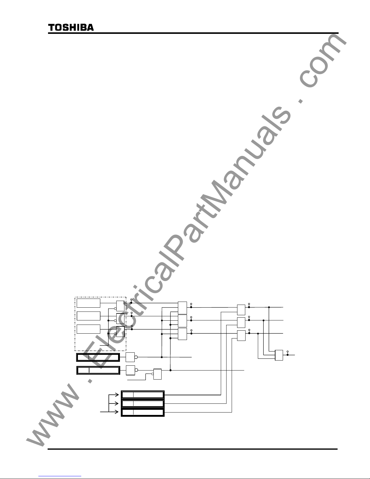
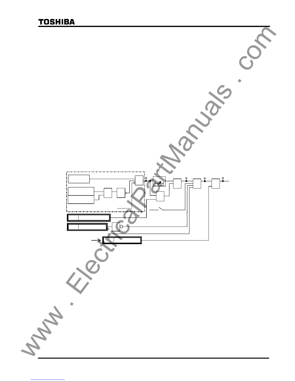
Figure 2.2.2.1 shows the scheme logic of the segregated-phase current differential protection.
Output signals of differential elements DIF-A, -B and -C can perform instantaneous tripping of
the breaker on a per phase basis and start the incorporated autoreclose function.
Note: For the symbols used in the scheme logic, see Appendix L.
DIF.FS-A_TP
DIF.FS-B_TP
DIF.FS-C_TP
DIF-A
&
41
&
82: DIF-A_TRIP
&
401
DIF-B
&
42
&
83: DIF-B_TRIP
&
DIF-C
&
Communication
failure, etc.
43
&
1
CRT_BLOCK
1544
84: DIF-C_TRIP
&
DIF-A_FS
1616
DIF-B_FS
1617
DIF-C_FS
1618
403
402
≥1
400
DIF.FS_TRIP
43C ON
&
TELEPROTECTION OFF
(
from IEC103 command)
DIFFS
1
DIF_BLOCK
1585
DIF BLOCK
Figure 2.2.2.1 Scheme Logic of Segregated-phase Current Differential Protection
www . ElectricalPartManuals . com
13
6 F 2 S 0 8 5 0
Tripping output signals can be blocked by the PLC command DIF_BLOCK and CRT_BLOCK.
The output signals of DIF-A, DIF-B and DIF-C are also blocked when a communication circuit
failure is detected by the data error check, sampling synchronism check or interruption of the
receive signals. For DIF-A_FS, DIF-B_FS and DIF-C_FS signals, see Section 2.2.4.
The differential elements DIF have a percentage restraining characteristic with weak restraint in
the small current region and strong restraint in the large current region, to cope with CT
saturation. (For details of the characteristic, see Section 2.16.)
Erroneous current data may be transmitted from the remote terminal when the remote relay is
out-of-service for testing or other purposes. To prevent false operation in this case, the relay sets
the receiving current data to zero in the differential current calculation upon detecting that the
remote terminal is out-of-service.
If the relay is applied to a three-terminal line, the zero setting is performed only for the current
data received from an out-of-service terminal.
Figure 2.2.2.2 shows the remote terminal out-of-service detection logic. The local terminal
detects that the remote terminal is out-of-service by receiving a signal LOCAL TEST which is
transmitted when the scheme switch [L. TEST] is set to "ON" at the terminal under test. As an
alternative means, the local terminal can detect it by using the circuit breaker and disconnector
status signal CBDS-A, B and C transmitted from the remote out-of-service terminal. The signal
CBDS-A is "1" when both the circuit breaker and disconnector are closed. Thus, out-of-service
is detected when either the circuit breaker or disconnector is open in all three phases.
Zero setting of the receive current data is also performed at the terminal under test. If the scheme
switch [L. TEST] is set to "ON" or the signal R.DATA_ZERO is input by PLC, all the receive
current data transmitted from the in-service terminal is set to zero and this facilitates the local
testing. The zero setting of the receive current data is not performed by the alternative way as
mentioned above.
The out-of-service detection logic can be blocked by the scheme switch [OTD].
REM1_IN_SRV: Remote 1 in-service
REM1_OFF_SRV: Remote 1 out-of-service
REM1_NON_USE: Remote 1 not used
1
≥
1
REM1_OFF_SRV
LOCAL_TEST1
CBDS-A
CBDS-B
CBDS-C
[OTD]
"ON"
(+)
&
[Open1]
"ON"
(+)
1
≥1
1
REM1_NON_USE
REM1_IN_SRV
207
208
209
≥
1
R.DATD_ZERO
1623
≥
1
(∗) Out-of-service detection logic for the remote 2 is same as above.
Figure 2.2.2.2 Out-of-Service Detection Logic
Note: When a communication circuit is disconnected or communication circuit failure occurs, do
not close the circuit breaker. When closing it, make sure that the DIF element is blocked.
(Otherwise, it may cause malfunction.)
2.2.3 Zero-phase Current Differential Protection
The GRL100 provides sensitive protection for high-impedance earth faults by employing
zero-phase current differential protection. For more sensitive protection, residual current is
introduced through an auxiliary CT in the residual circuit instead of deriving the zero-phase
current from the three phase currents.
The zero-phase current differential element has a percentage restraining characteristic with weak
www . ElectricalPartManuals . com
14
6 F 2 S 0 8 5 0
restraint. For details of the characteristic, see Section 2.16.
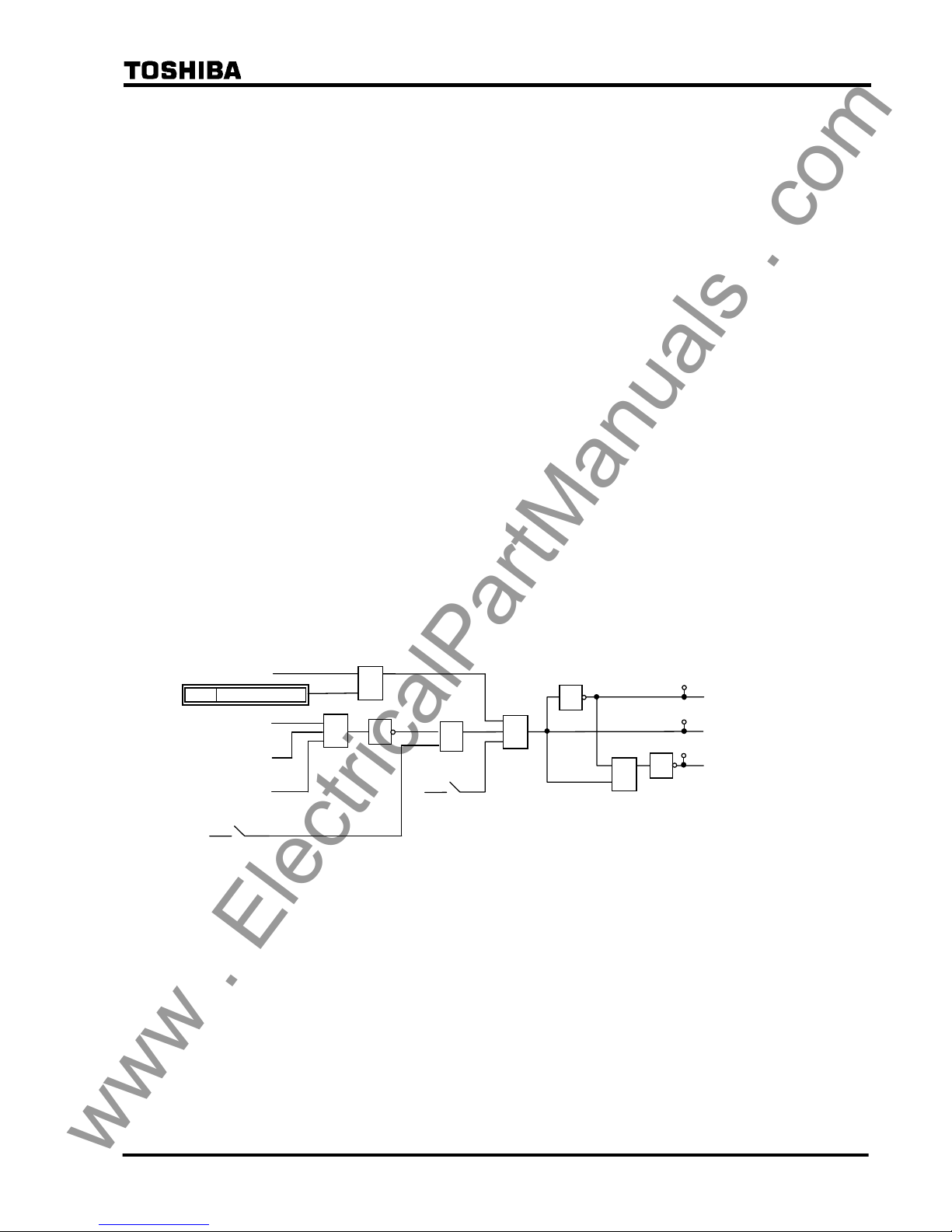
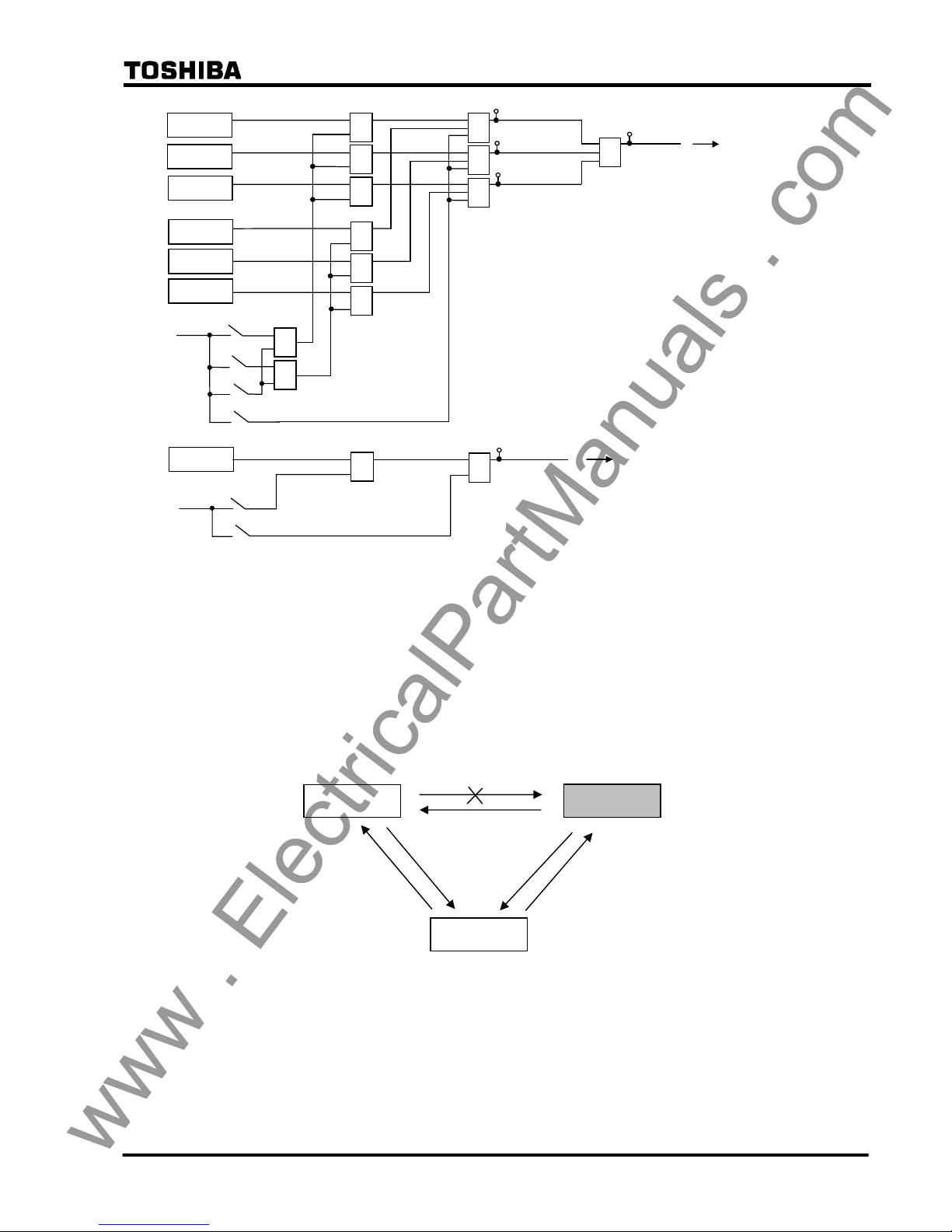
The scheme logic is shown in Figure 2.2.3.1. The output signal of the differential element DIFG
performs time-delayed three-phase tripping of the circuit breaker with the tripping output signal
DIFG.FS_TRIP. DIFG.FS_TRIP can start the incorporated autoreclose function when the
scheme switch [ARC-DIFG] is set to "ON". The DIFG can trip instantaneously by PLC
command DIFG_INST_TP.
Tripping output signal can be blocked by the PLC command DIFG_BLOCK and CRT_BLOCK.
The output signal is also blocked when a communication circuit failure is detected by data error
check, sampling synchronism check or interruption of the receive signals. For DIFG_FS signal,
see Section 2.2.4.
Since the DIFG is used for high-impedance earth fault protection, the DIFG output signal is
blocked when zero-phase current is large as shown in the following equation:
Σ I
01 ≥ 2 pu or Σ I02 ≥ 2 pu
where,
Σ I
01: Scalar summation of zero-phase current at local terminal relay
Σ I
02: Scalar summation of zero-phase current at remote terminal relay
pu: per unit value
In GPS-mode setting and backup mode (refer to 2.2.7.2), DIFG is blocked.
DIFG
DIFG.FS_TRIP
"ON"
&
1
ΣI01≥2PU
ΣI02≥2PU
≥1
Communication failure, etc.
1
DIFG_BLOCK
1586
85
44
DIFG_FS
1619
&
404
43C ON
86
DIFG_TRIP
DIFGFS
DIFG_INST_TP
1632
≥1
&
+
[DIFG]
t 0
TDIFG
0.0-10.0s
&
Figure 2.2.3.1 Scheme Logic of Zero-phase Current Differential Protection
2.2.4 Fail-safe Function
GRL100 provides OC1, OCD and EFD elements. These are used for fail-safe to prevent
unnecessary operation caused by error data in communication failure. OC1 is phase overcurrent
element and its sensitivity can be set. OCD is phase current change detection element, and EFD
is zero-sequence current change detection element. Both of the OCD and EFD sensitivities are
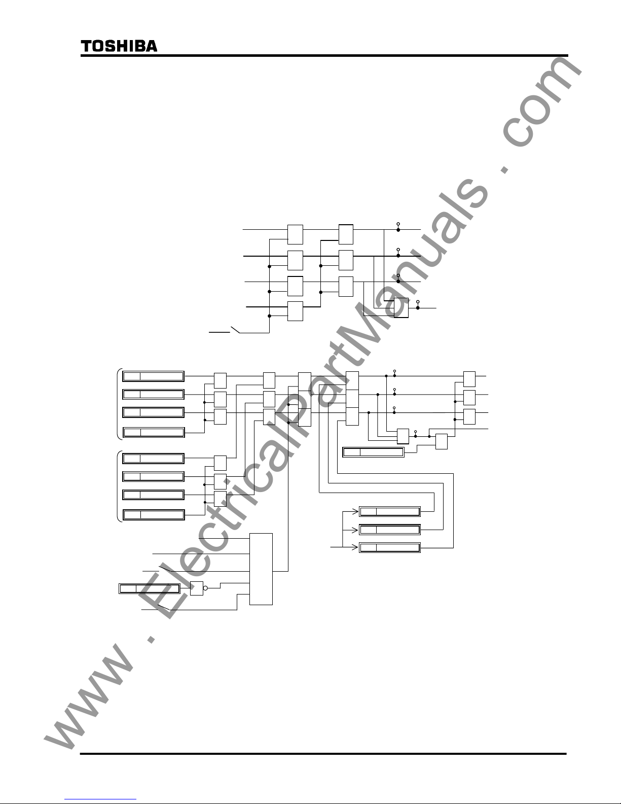
fixed. The scheme logic is shown in Figure 2.2.4.1.
The outputs of DIF.FS_OP and DIFG.FS_OP signals are connected to DIF-A_FS, DIF-B_FS,
DIF-C_FS and DIFG_FS respectively by PLC function. These are connected at the default
setting.
The fail-safe functions are disabled by [DIF-FS] and [DIFG-FS] switches. In the [DIF-FS], OC1
or OCD or both elements can be selected. If these switches are set to “OFF”, the signals of
DIF.FS_OP and DIFG.FS_OP are “1” and the fail-safe is disabled.
www . ElectricalPartManuals . com
15
6 F 2 S 0 8 5 0
DIF.FS-A_OP
OC1-A
OC1-B
OC1-C
OCD-A
OCD-B
OCD-C
[DIF-FS]
"BOTH"
"OCD"
"
OFF"
"OC"
+
&
&
&
&
≥
1
≥1
&
&
≥1
≥
1
≥1
409
DIF.FS-B_OP
410
DIF.FS-C_OP
411
DIF.FS_OP
408
EFD
&
≥
1
DIFG.FS_OP
412
[DIFG-FS]
"ON"
+
"OFF"
DIFG_FS
(see Fig. 2.2.3.1.)
DIF-A_FS
DIF-B_FS
DIF-C_FS
(see Fig. 2.2.2.1.)
≥1
Figure 2.2.4.1 Fail-safe Logic
2.2.5 Remote Differential Trip
Note: This function is available only when the three-terminal protection is applied by
setting the scheme switch [TERM] to “3-TERM”. In the case of A-MODE setting,
this function is not available.
When one of the telecommunication channels fails, the terminal using the failed channel is
disabled from performing current differential protection, as a result of the failure being detected
through by the telecommunication channel monitoring.
Figure 2.2.5.1 Protection Disabled Terminal with Channel Failure
The remote differential trip (RDIF) function enables the disabled terminal to trip by receiving a
trip command from the sound terminal, which continues to perform current differential
protection.
Figure 2.2.5.2(a) and (b) show the RDIF scheme logic at RDIF command sending terminal (=
sound terminal) and command receiving terminal (= disabled terminal). The sound terminal
GRL100
GRL100
GRL100
www . ElectricalPartManuals . com
16
6 F 2 S 0 8 5 0
sends the command when the tripping signals RDIF-A-S, RDIF-B-S, RDIF-C-S or RDIF-S are
output locally and the scheme switches [RDIF] and [TERM] are set to “ON” and “3-TERM”
respectively. The RDIF command is sent to the remote terminal via the 64kb/s digital link
together with other data and signals.
The receiving terminal outputs a local three-phase trip signal RDIF-TRIP under the conditions
that when the command RDIF1 or RDIF2 is received from either of the remote terminals, local
differential protection does not operate, the scheme switches [RDIF] and [TERM] are set to
“ON” and “3-TERM” respectively and no communication channel failure exists in the channel
which received the RDIF command.
When the RDIF function is applied, the command sending signals and receiving signals must be
assigned by PLC function.
DIF-A_TRIP
[RDIF]
+
“ON”
&
&
&
DIF-B_TRIP
DIF-C_TRIP
451
≥
1
≥
1
≥
1
452
DIF-G_TRIP
&
453
RDIF-A-S
RDIF-B-S
RDIF-C-S
≥
1
RDIF-S
454
(a) Sending terminal
RD.FS-A TP
456
&
455
457
458
≥
1
≥
1
≥
1
RDIF-A-R1
1684
RDIF-B-R1
1685
RDIF-C-R1
1686
≥
1
1
RDIF_BLOCK
1598
RDIF-R1
1687
&
&
&
&
&
&
RDIF_3PTP
1649
≥
1
≥
1
≥
1
RD.FS-B TP
RD.FS-C TP
RD.FS_TRIP
RD.FS-A_ TRIP
Receiving
signal from
Remote
Terminal 1
≥
1
≥
1
≥
1
≥
1
≥
1
≥
1
RDIF-A-R2
1716
RDIF-B-R2
1717
RDIF-C-R2
1718
RDIF-R2
1719
Receiving
signal from
Remote
Terminal 2
43C ON
+
“ON”
[RDIF]
[TERM]
+
“3-TERM”
&
RD.FS-B_ TRIP
RD.FS-C_ TRIP
RDIF-A_FS
1624
RDIF-B_FS
1625
RDIF-C_FS
1626
DIF elements not operated
DIF.FS_OP
(b) Receiving Terminal
Figure 2.2.5.2 Remote Differential Trip
www . ElectricalPartManuals . com

17
6 F 2 S 0 8 5 0
2.2.6 Transmission Data
The following data are transmitted to the remote terminal via the 64kb/s digital link. The data
depends on the communication mode and whether a function is used or not. The details are
shown in Appendix N.
A-phase current
B-phase current
C-phase current
Residual current
Positive sequence voltage
A-phase differential element output signal
B-phase differential element output signal
C-phase differential element output signal
A-phase breaker and disconnector status
B-phase breaker and disconnector status
C-phase breaker and disconnector status
Scheme switch [LOCAL TEST] status
Scheme switch [TFC] status
Reclose block command
Sampling synchronization control signal
Synchronized test trigger signal
User configurable data
Current and voltage data are instantaneous values which are sampled every 30 electrical degrees
(12 times per cycle) and consist of eleven data bits and one sign bit. This data is transmitted
every sample to the remote terminal.
Three differential element outputs and the transfer trip command are related to remote terminal
tripping and are transmitted every sampling interval.
Other data is transmitted once every power cycle.
The data transmission format and user configurable data are also shown in Appendix N.
A synchronized test trigger signal is used to test the differential protection simultaneously at all
terminals. For details, see Section 6.5.3.
In addition to the above data, cyclic redundancy check bits and fixed check bits are transmitted to
monitor the communication channel. If a channel failure is detected at the local terminal, all the
local and remote current and voltage data at that instant are set to zero and outputs of the
differential protection and out-of-step protection are blocked, and these protections of remote
terminal are also blocked because the channel failure is also detected at the remote terminal.
2.2.7 Synchronized Sampling
The GRL100 performs synchronized simultaneous sampling at all terminals of the protected
line. Two methods are applied for the sampling synchronization; intra-system synchronization
and GPS-based synchronization. The former is applied to communication modes A-MODE and
www . ElectricalPartManuals . com
18
6 F 2 S 0 8 5 0
B-MODE, and the latter is applied to GPS-MODE.
The intra-system synchronization keeps the sampling timing error between the terminals within
±10µs or ±20µs and the GPS-based system keeps it within ±5µs or ±10µs for two- or
three-terminal applications.
In both methods, the sampling synchronization is realized through timing synchronization
control and sampling address synchronization control. These controls are performed once every
two power cycles.
2.2.7.1 Intra-system Synchronized Sampling for A-MODE and B-MODE
The synchronized sampling is realized using sampling synchronization control signals
transmitted to other terminals together with the power system data. This synchronized sampling
requires neither an external reference clock nor synchronization of the internal clocks of the
relays at different terminals. The transmission delay of the channel is corrected automatically.
Timing synchronization
One of the terminals is selected as the time reference terminal and set as the master terminal. The
other terminal is set as the slave terminal. The scheme switch [SP.SYN] is used for the settings.
Note: The master and slave terminals are set only for the convenience of the sampling timing
synchronization. The GRL100s at all terminals perform identical protection functions and
operate simultaneously.
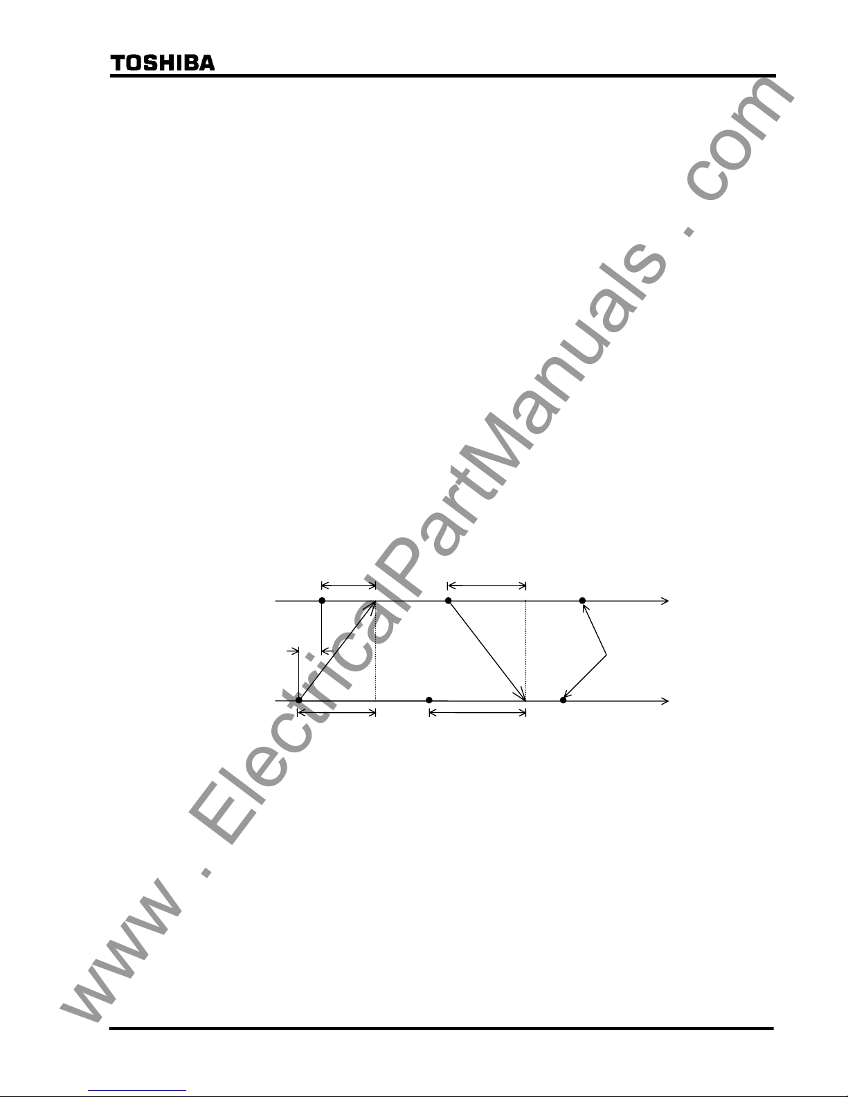
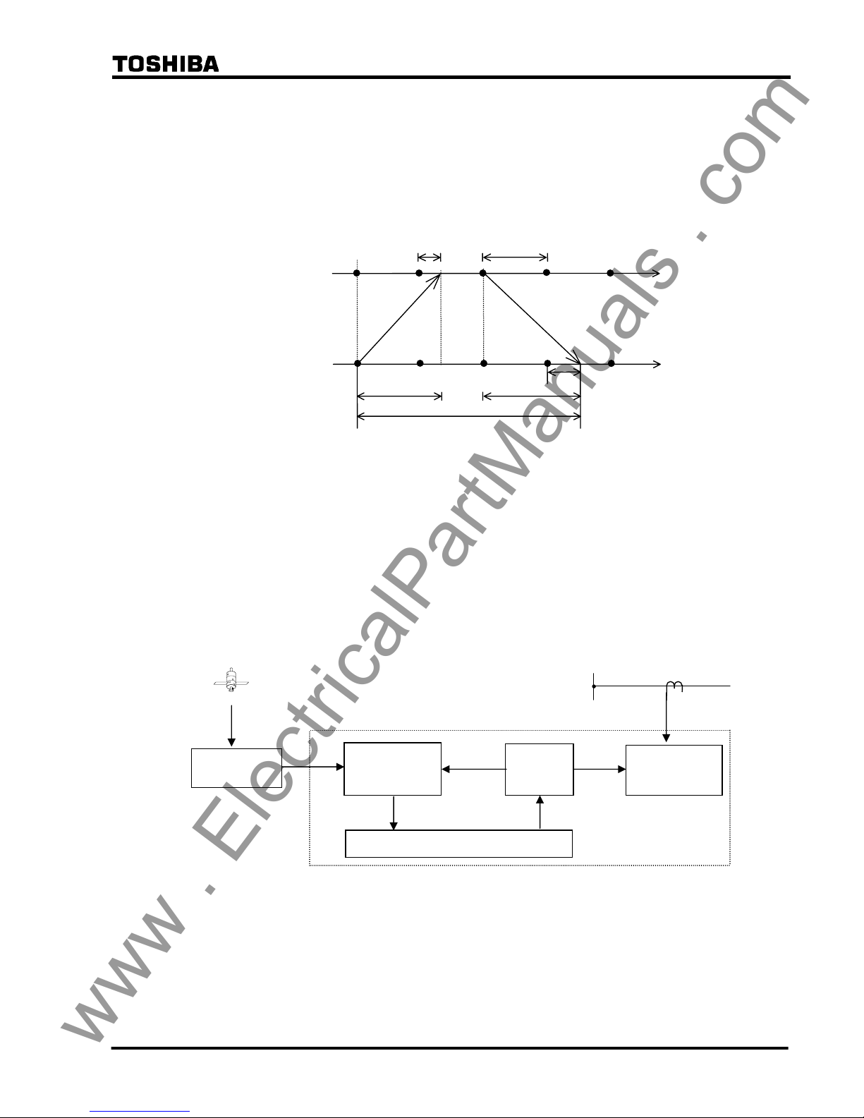
To perform timing synchronization for the slave terminal, the sampling time difference between
master and slave terminals is measured. The measurement principle of the sampling time
difference ∆T is indicated in Figure 2.2.7.1. The master terminal and slave terminal perform
their own sampling and send a signal that becomes the timing reference for the other terminal.
t
t
Master
terminal
TM
∆T
Slave
terminal
T
d2
Td1
Sampling
timing
T
F
Figure 2.2.7.1 Timing Synchronization
Each terminal measures the time TM and TF from its own sampling instant to the arrival of the
signal from the other terminal. As is evident from the figure, the times TM and TF can be
obtained by equation (1) and (2) where Td1 and Td2 are the transmission delay of the channel in
each direction. The sampling time difference ∆T can be obtained from the resulting equation (3).
TM = T
d1
− ∆T (1)
TF = T
d2
+ ∆T (2)
∆T = {(TF − T
M
) + (T
d1
− T
d2
)}/2 (3)
The slave terminal advances or retards its sampling timing based on the time ∆T calculated from
equation (3), thereby reducing the sampling time difference with the master terminal to zero.
This adjustment is performed by varying the interval of the sampling pulse generated by an
www . ElectricalPartManuals . com
19
6 F 2 S 0 8 5 0
oscillator in the slave terminal.
The difference of the transmission delay time Tdd (= T
d1
− T
d2
) is set to zero when sending and
receiving take the same route and exhibit equal delays. When the route is separate and the
sending and receiving delays are different, Tdd must be set at each terminal to be equal to the
sending delay time minus the receiving delay time. The maximum Tdd that can be set is 10ms.
(For setting, see Section 4.2.6.7. The setting elements of transmission delay time difference are
TCDT1 and TCDT2.)
The time TM measured at the master terminal is sent to the slave terminal together with the
current data and is used to calculate the ∆T.
The permissible maximum transmission delay time of the channel is 10ms.
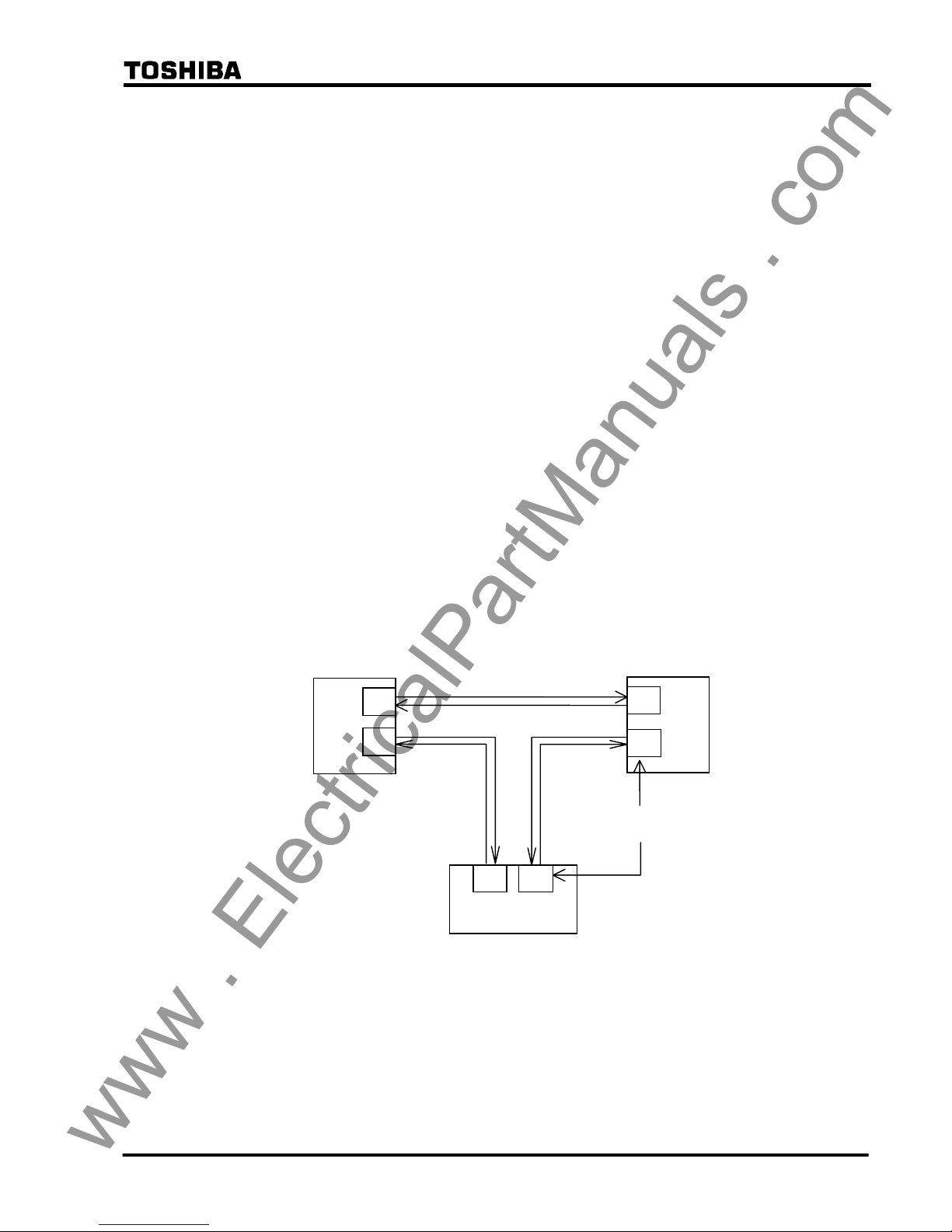
In case of the three-terminal line application, the communication ports of the GRL100 are
interlinked with each other as shown in Figure 2.2.7.2, that is, port CH1 of one terminal and port
CH2 of the other terminal are interlinked. For the setup of the communication system, see
Section 2.2.13.3.
When terminal A is set as the master terminal by the scheme switch [SP.SYN], the
synchronization control is performed between terminals A and B, and terminals B and C. The
terminal B follows the terminal A and the terminal C follows the terminal B. The slave terminals
perform the follow-up control at their communication port CH2.
When the master terminal is out-of-service in A-MODE, the slave terminal that is interlinked
with port 1 of the master terminal takes the master terminal function. In the case shown in Figure
2.2.7.2, terminal B takes the master terminal function when the master terminal A is
out-of-service. In B-MODE and GPS-MODE, even if the master terminal is out-of-service, the
master terminal is not changed. If DC power supply of the out-of-service terminal is “OFF”,
differential elements at all terminals are blocked. Therefore, the [TERM] setting change from
“3TERM” to “2TERM” is required.
GRL100
Terminal B
Terminal A
Terminal C
CH1
Communication
port
GRL100
GRL100
Master
Slave
Slave
CH2
CH1
CH2
CH1 CH2
Figure 2.2.7.2 Communication Link in Three-terminal Line
Sampling address synchronization
The principle of sampling address synchronization control is indicated in Figure 2.2.7.3. After
time synchronization has been established, the slave terminal measures the time from sending its
own timing reference signal until it returns from the master terminal. The transmission delay
time Td1 from slave to master terminal can be calculated from equation (4).
www . ElectricalPartManuals . com
20
6 F 2 S 0 8 5 0
Td = ({T
o
− (T − TM)}/2 + T
dd
)/2 (4)
The calculated transmission delay time Td1 is divided by the sampling interval T. The mantissa
is truncated and the quotient is expressed as an integer. If the integer is set to P, the reception at
the slave terminal of the signal sent from the master terminal occurs at P sampling intervals from
the transmission. Accordingly, by performing control so that the sampling address of the slave
terminal equals integer P when the sampling address = 0 signal is received from the master
terminal, the sampling address of the slave terminal can be made the same as the master terminal.
t
t
Master
terminal
T
M
Slave
terminal
T
T
d2
T
d1
T
O
T
F
Figure 2.2.7.3 Sampling Address Synchronization
2.2.7.2 GPS-based Synchronized Sampling for GPS-MODE
The relays at all terminals simultaneously receive the GPS clock signal once every second.
Figure 2.2.7.4 shows the GPS-based synchronized sampling circuit at one terminal. The GPS
clock signal is received by the GPS receiver HHGP1 and input to a time difference measurement
circuit in the GRL100. The circuit measures the time difference ∆T between the GPS clock and
the internal clock generated from the crystal oscillator. The oscillator is controlled to
synchronize with the GPS clock using the measured ∆T and outputs 2,400 Hz (50Hz rating)
sampling signals to the current sampling circuit (analog to digital converter).
Figure 2.2.7.4 GPS Clock-based Sampling
GPS
GPS receiver
HHGP1
Time
difference
measurement
Crystal
oscillator
Analog/digital
converter
Synchronous control
ΔT
Lead/lag control
GRL100
Line
www . ElectricalPartManuals . com

21
6 F 2 S 0 8 5 0
Timing synchronization
When the GPS signal is received normally at every line terminal, the GRL100 performs
synchronized sampling based on the received clock signal. The GRL100 can provide a backup
synchronization system if the GPS signal is interrupted at one or more terminals, and perform
synchronized sampling without any external reference clock. The backup system becomes valid
by setting the scheme switch [GPSBAK] to "ON".
In the backup modes, the percentage restraint in the small current region can be increased from
the normal 16.7% ((1/6)Ir in Figure 2.16.1.1) in accordance with the PDTD setting which is the
probable transmission delay time difference between send and receive channels.
Backup modes, Mode 1, 2A and 2B are initialised when the backup system is set valid.
If the GPS signal interruption occurs when the backup is set invalid, the sampling runs based on
the local clock. When the arrival time of the remote signal measured from local sampling instant
deviates from a nominal time, the protection is blocked.
Mode 0: When the GPS signal is received normally, the sampling is performed synchronizing
with the received clock signal thus realizing synchronized sampling at all terminals. Difference
of the transmission delay time for the channel in each direction and fluctuation of the delay time
can be permitted.
The GRL100 performs the protection based on the nominal current differential characteristics.
When the GPS signal has interrupted for more than ten seconds at any of the terminals, the mode
changes to Mode 1 at all terminals.
Mode 1: The terminal which loses its GPS signal first functions as the slave terminal. If all
terminals lose their signals simultaneously, then the scheme switch [SP.SYN] setting determines
which terminal functions as the slave or master. The slave terminal adjusts the local sampling
timing to synchronize the sampling with other terminal which is receiving the GPS signal
regularly or with the master terminal.
Note: When two terminals are receiving the GPS signal regularly, the slave terminal
synchronizes with the terminal that is interlinked with port 2 of the slave terminal.
When the GPS signal has been restored, the mode shifts from Mode 1 back to Mode 0.
If, during Mode 1 operation, a failure occurs in the communication system, the sampling timing
adjustment is disabled and each terminal runs free. If the free running continues over the time
determined by the PDTD setting or the apparent phase difference exceeds the value determined
by the PDTD setting, the mode shifts from Mode 1 to Mode 2A at all terminals.
Mode 2A: In this mode, the intra-system synchronization described in 2.2.7.1 is applied
assuming that the transmission delay time for the channel in each direction is identical.
Fluctuation of the delay time can be permitted.
The current differential protection is blocked in this mode.
When the GPS signal has been restored, the mode shifts from Mode 2A to Mode 0.
If the GPS signal interruption occurs a set period following energisation of the relay power
supply or the mode returned to Mode 0 from Mode 1, 2A or 2B, then the transmission delay time
measurement will not be completed in Mode 0, and the mode changes to Mode 2A.
When the apparent current phase difference has stayed within the value determined by the PDTD
setting, the scheme switch [AUTO2B] for automatic mode change is set to "ON" and [TERM] is
set to "2TERM", the mode changes from Mode 2A to Mode 2B at both terminals.
The mode can be changed to Mode 2B manually through a binary input signal "Mode 2B
initiation" or user interface. Before this operation, it must be checked that the transmission delay
www . ElectricalPartManuals . com

22
6 F 2 S 0 8 5 0
time difference between send and receive terminals is less than the PDTD setting and the SYNC
ALARM LED is off. If these conditions are not satisfied, the operation may cause a false
tripping.
Note: The mode change with the binary input signal is performed by either way:
• If the binary input contact is such as to be open when the relay is in service, set
the BI to "Inv" (inverted). The mode changes when the contact is closed more
than 2 seconds and then open.
• If the binary input contact is such as to be closed when the relay is in service, set
the BI to "Norm" (normal). The mode changes when the contact is open more
than 2 seconds and then closed.
For the BISW4, see Section 3.2.1.
In the three-terminal application, the mode change to Mode 2B is available even
when one of the three communication routes is failed.
Mode 2B: The same intra-system synchronization as in Mode 2A is applied.
When the GPS signal has been restored, the mode shifts from Mode 2B to Mode 0.
If a failure occurs in the communication system, the sampling timing adjustment is disabled and
each terminal runs free.
The mode shifts from Mode 2B to Mode 2A, when the apparent load current phase difference
exceeds the value determined by the PDTD setting for pre-determined time.
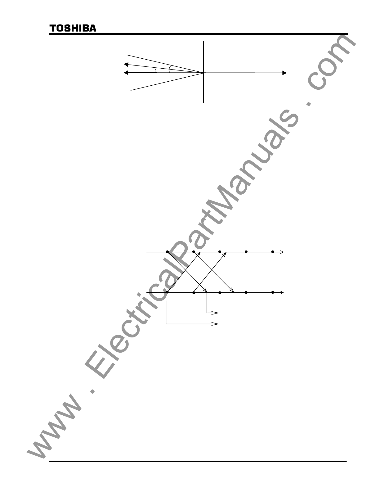
Checking the current phase difference (For two-terminal application setting only)
The current phase difference is checked using the following equations:
I
1A ⋅ cos θ < 0
I
1A ⋅ I1B sin θ < I1A ⋅ I1B sin θs
I
1A > OCCHK
I
1B > OCCHK
Where,
I
1A = Positive sequence component of load current at local terminal
I
1B = Positive sequence component of load current at remote terminal
θ = Phase difference of I
1B from - I1A
θs = Critical phase difference
= CHKθ‐HYSθ
CHKθ =
PDTD(µs)
2
×
360°
20000(µs)
+ 8.5°
HYSθ = Margin of phase difference checking
OCCHK = Minimum current for phase difference check
If the magnitude of I
1A and I1B exceed the setting and the conditions for both equations above are
established, then the sampling is regarded to be synchronized.
If the current phase difference exceeds a set value, the "SYNC ALARM" LED on the front panel
is lit.
Checking the current phase difference is enabled by setting the scheme switches [TERM] to
"2TERM" and [SRCθ] to "I".
www . ElectricalPartManuals . com
23
6 F 2 S 0 8 5 0
I1A
I1B
-I1A
θ
s
θ
Figure 2.2.7.5 Current Phase Difference Check
Sampling address synchronization
The same method as described in section 2.2.7.1 is employed in Mode 0 and Mode 2A where the
sampling synchronization must be established. It is not employed in Mode 1 and 2B because the
sampling address synchronization has already been established in the previous mode.
2.2.7.3 Differential Current Calculation
Synchronized sampling allows correct calculation of differential current even in the presence of
a transmission time delay. This processing is indicated in Figure 2.2.7.4. As indicated in the
figure, sampling synchronization is established between terminals A and B, and both the
sampling timing and sampling address match. The instantaneous current data and sampling
address are both sent to the other terminal. The GRL100 refers to the sampling address affixed to
the received data and uses local data with the same sampling address to calculate the differential
current. This allows both terminals to use data sampled at the same instant to perform the
differential current calculation, no matter how large the transmission time delay is.
t
t
Terminal A
Terminal B
4 3210
i
B(1)
i
A(0)
i
B(0)
i
A(1)
4 3210
Sampling address number
i
A(0)
Differential current calculation
i
B(0)
Figure 2.2.7.4 Calculation of Differential Current with Transmission Delay Time
Protection in anomalous power system operation
Even when any of the terminals is out-of-service, the GRL100 in-service terminal can still
provide the differential protection using the out-of-service detection logic. For details of the
out-of-service detection logic, see Section 2.2.2.
When one terminal is out-of-service in a two-terminal line, the other terminal continues the
current differential protection using the local current irrespective of whether it is a master
terminal or a slave terminal.
When one terminal is out-of-service in a three-terminal line, synchronized sampling is
established between the remaining two terminals as follows and the differential protection is
maintained.
• If the master terminal is out-of-service, one of the slave terminals takes over the master
terminal synchronized sampling function and enables current differential protection
www . ElectricalPartManuals . com

24
6 F 2 S 0 8 5 0
between the remaining terminals to be performed.
• If the slave terminal is out-of-service, the master and another slave terminal maintain the
differential protection.
When two terminals are out-of-service in a three-terminal line, the remaining terminal continues
the current differential protection using the local current irrespective of whether it is a master
terminal or a slave terminal.
2.2.8 Charging Current Compensation
When differential protection is applied to underground cables or long overhead transmission
lines, the charging current which flows as a result of the capacitance of the line (see Figure
2.2.8.1) appears to the protection relay as an erroneous differential current.
GRL100 GRL100
Terminal A Terminal B
Ic
Figure 2.2.8.1 Charging Current
The charging current can be compensated for in the setting of the relay’s differential protection
sensitivity but only at the expense of reduced sensitivity to internal faults. In addition, the actual
charging current varies with the running voltage of the line and this must be taken into account in
the setting.
In order to suppress the effect of the charging current while maintaining the sensitivity of the
differential protection, GRL100 is equipped with a charging current compensation function,
which continuously re-calculates the charging current according to the running line voltage and
compensates for it in its differential current calculation. The running line voltage is measured by
VT inputs to GRL100.
The user enters values for line charging current and for the line voltage at which that charging
current was determined in the settings [DIFIC] and [Vn], and these values are used by the relay
to calculate the capacitance of the line. The relays at each line end share the line capacitance
between them, that is they divide by two for a two-terminal line, and by three for a three-terminal
line. In the case of a three-terminal line, if the relay at one terminal is out-of-service for testing
(see out-of-service terminal detection), the other two terminals are automatically re-configured
to divide the line capacitance by two.
Each terminal continuously calculates its share of the charging current at the running line voltage
on a sample by sample basis as follows:
Ic = C
dV
/ dt
where,
Ic = line charging current
C = line capacitance calculated from settings [DIFIC] and [Vn]
V = measured line voltage
The relay then calculates the line current compensated for the charging current on a sample by
sample basis as follows:
www . ElectricalPartManuals . com

25
6 F 2 S 0 8 5 0
I = I’ - Ic
where,
I = compensated current
I’ = actual measured current
Note that since GRL100 calculates both the charging current and compensated line current on a
sample by sample basis, all necessary phase information is inherently taken into account.
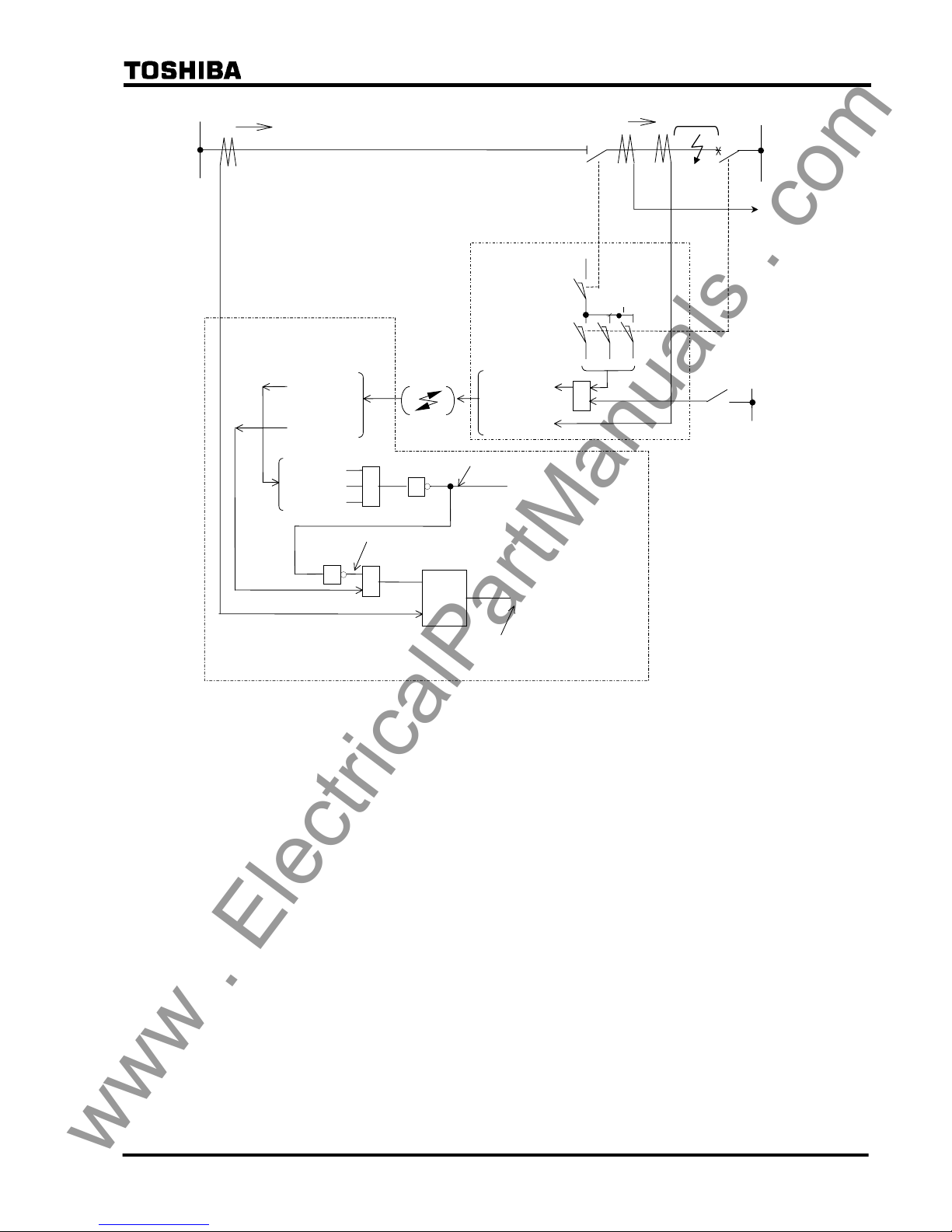
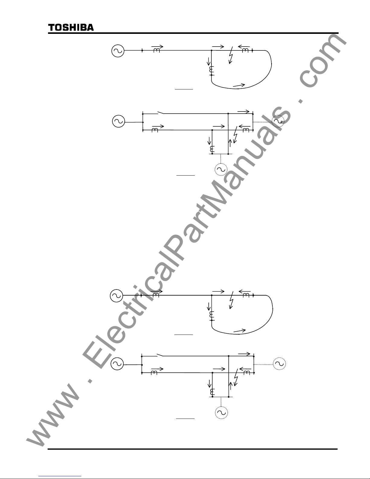
2.2.9 Blind Zone Protection
The GRL100 relay has “Out-of-Service Detection Logic” as described in Section 2.2.2. This
logic functions automatically to detect the remote CB or DS (line disconnecting switch) opened
condition as shown in Figure 2.2.9.1. If the remote CB or DS is opened, the received remote
current data is set to “zero” Ampere at the local terminal, and the local relay can be operated with
only local current like a simple over current relay. Therefore, this logic function is used for blind
zone protection.
The zone between CB and CT at the remote terminal is the blind zone in Figure 2.2.9.1. If a fault
occurs within this zone, the busbar protection should operate first and trip the CB at the remote
terminal, but the fault remains and the fault current (IF) is fed continuously from the local
terminal. Since this phenomenon is an external fault for the current differential protection
scheme, the blind zone fault cannot be cleared. The fault may be cleared by remote backup
protection following a time delay, but there is a danger of damage being caused to power system
plant. Fast tripping for this type of fault is highly desirable. The Out-of-Service Detection Logic
is effective for a fault where a blind zone between CT and CB on the line exists as shown in
Figure 2.2.9.1.
If the CB and DS condition are introduced at the remote terminal as shown in Figure 2.2.9.1, the
GRL100 relay at the local terminal can operate with only local current and the fault can be
cleared, because the remote current data is automatically cancelled as explained above.
Please note the “CB Close Command” signal must be connected to the GRL100 relay to prevent
unwanted operation for a CB close operation (manual close and/or autoreclose). Unwanted
operation may be caused if the close timing of the CB auxiliary contact is delayed relative to the
CB main contact. Therefore, the CB close command signal resets forcibly the Out-of-Service
Detection Logic before the CB main contact is closed.
CB and DS status signals are input by PLC. If the out-of-service detection is not used, its logic
can be blocked by the scheme switch [OTD].
www . ElectricalPartManuals . com
26
6 F 2 S 0 8 5 0
DS
IR (=IF)
IL (=IF)
LINE
REMOTE
LOCAL
52A 52C 52B
89L1
IR(Current)
IR(Current)
CBDS-C
CBDS-B
(Remote terminal closed: “0” logic)
Differential Current (Id)
Remote terminal “OPEN”
CBDS-A
Comm. Link
CBDS-A,B,C
CBDS-A,B,C
DIFF RELAY GRL100
(REMOTE)
DIFF RELAY GRL100
(LOCAL)
1
&
≧1
1
If DS or CB signals (CBDS-A, B, C) changes to “0”, remote current data
(IR) is cancelled to zero (0). Therefore, differential current (Id) equals to
local current (IL).
(Cancel circuit of remote terminal current IR)
Σ
BUSBAR
PROT.
CB
FAULT
≧
1
CB CLOSE COMMAND
IR
IL
Blind Zone
Figure 2.2.9.1 Blind Zone Protection
2.2.10 Application to Three-terminal Lines
When current differential protection is applied to a three-terminal line, special attention must be
paid to the fault current flowing out of the line in the case of an internal fault and CT saturation at
the outflowing terminal in case of an external fault.
Fault current outflow in case of internal fault
In case of a two-terminal line, fault current never flows out from the terminals for an internal
fault. But in case of a three-terminal line with an outer loop circuit, a partial fault current can
flow out of one terminal and flow into another terminal depending on the fault location and
magnitude of the power source behind each terminal.
Case 1 in Figure 2.2.10.1 shows a fault current outflow in a single circuit three-terminal line with
outer loop circuit. J and F in the figure indicate the junction point and fault point. A part of the
fault current flowing in from terminal A flows out once from terminal C and flows in again from
terminal B through the outer loop.
Case 2 shows the outflow in a double-circuit three-terminal line. The outer loop is generated
when one terminal is open in the parallel line. A part of the fault current flowing in from terminal
A flows out from the fault line to the parallel line at terminal C and flows in again at terminal B
through the parallel line.
www . ElectricalPartManuals . com
27
6 F 2 S 0 8 5 0
A
B F
Case 1
J
C
Case 2
A
J
B
F
C
Open
Figure 2.2.10.1 Fault Current Outflow in Internal Fault
The larger current outflows from terminal C when the fault location is closer to terminal B and
the power source behind terminal C is weaker. In case of a double-circuit three-terminal line,
50% of the fault current flowing in from terminal A can flow out from terminal C if terminal C is
very close to the junction and has no power source behind it.
These outflows must be considered when setting the differential element.
CT saturation for an external fault condition
In case of a two-terminal line, the magnitude of infeeding and outflowing currents to the external
fault is almost the same. If the CTs have the same characteristics at the two terminals, the CT
errors are offset in the differential current calculation.
A B
F
Case 1
J
C
Case 2
A
J
B
F
C
Open
Figure 2.2.10.2 Fault Current Distribution
www . ElectricalPartManuals . com
28
6 F 2 S 0 8 5 0
But in case of a three-terminal line, the magnitude of the current varies between the terminals
and the terminal closest to the external fault has the largest magnitude of outflowing fault
current. Thus, the CT errors are not offset in the differential current calculation. Thus, it is
necessary to check whether any fault causes CT saturation, particularly in the terminal with
outflow, and the saturation must be accommodated utilising the DIFI2 setting of the DIF
element.
2.2.11 Dual Communication Mode
Three-terminal application models have dual communication mode (GRL100-∗1∗). By
connecting the remote terminal with dual communication routes, even if one of the routes fails, it
is possible to continue sampling synchronization and protection by the current differential relay.
To set dual communication mode, select "Dual" in the TERM setting. Other settings are the same
as that of the two-terminal. In GPS-MODE setting, however, the dual communication mode
cannot be applied.
GRL100
GRL100
CH1
CH2
CH1
CH2
Figure 2.2.11.1 Dual Communication Mode
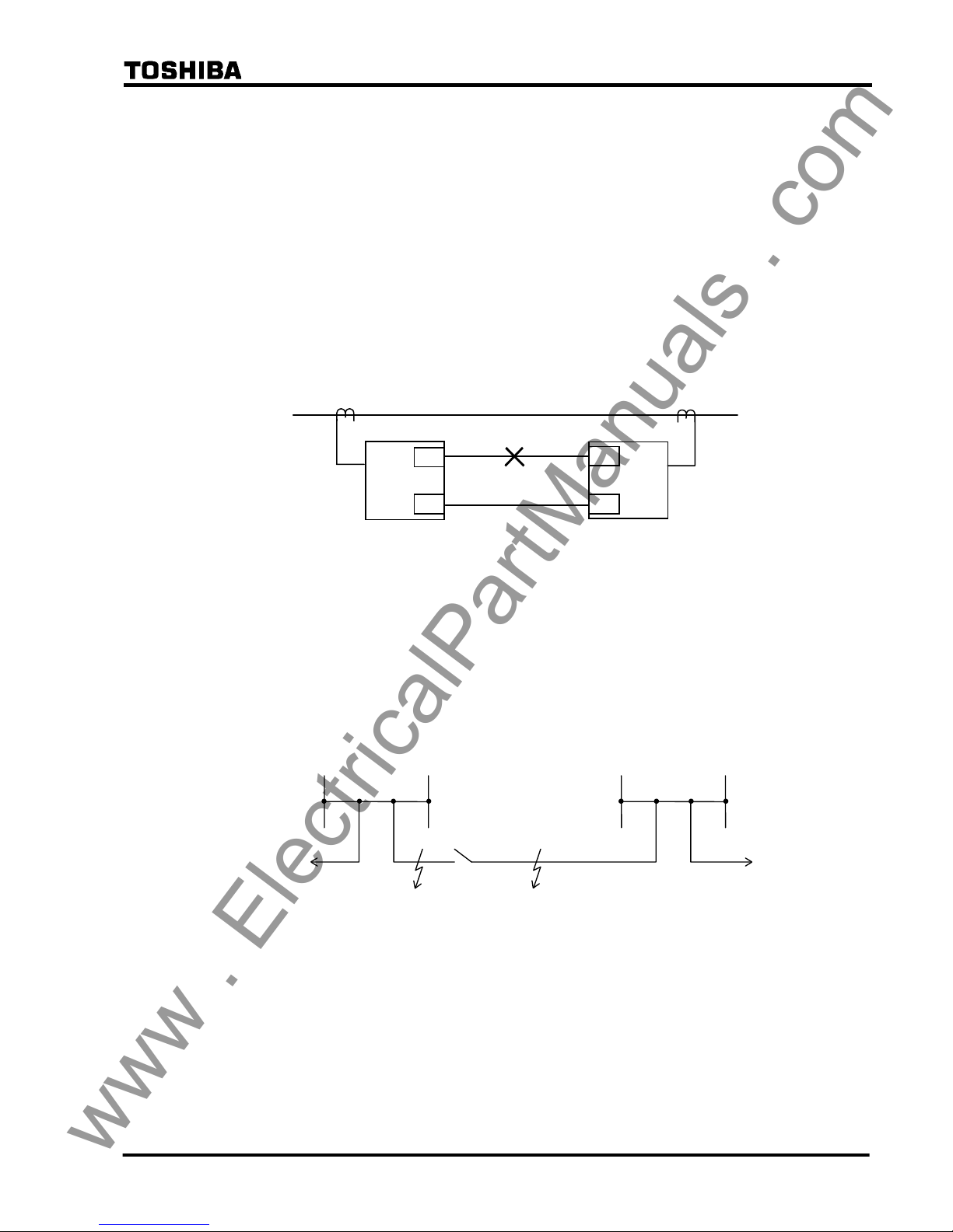
2.2.12 Application to One-and-a-half Breaker Busbar System
The GRL100-700 series can be used for lines connected via a one-and-a-half breaker busbar
system, and have functions to protect against stub faults and through fault currents.
Stub fault
If a fault occurs at F1 or F2 when line disconnector DS of terminal A is open as shown in Figure
2.2.12.1, the differential protection operates and trips the breakers at both terminals without any
countermeasures.
Terminal A
F2 F1
DS
×
× ×
Terminal B
× ×
×
Figure 2.2.12.1 Stub Fault
GRL100 provides stub protection to avoid unnecessary tripping of the breakers in these cases.
For the stub protection, see Section 2.13.
Fault current outflow in case of internal fault
As shown in Figure 2.2.12.2, the fault current may outflow in case of an internal fault of
double-circuit lines. The outflow at terminal A increases as the fault location F approaches
terminal B. When the fault is close to terminal B, 50% of the fault current flows out to the
parallel line, though it depends on the power source conditions at terminals A and B.
This outflow must be considered when setting the differential element.
www . ElectricalPartManuals . com
29
6 F 2 S 0 8 5 0
Figure 2.2.12.2 Fault Current Outflow in Internal Fault
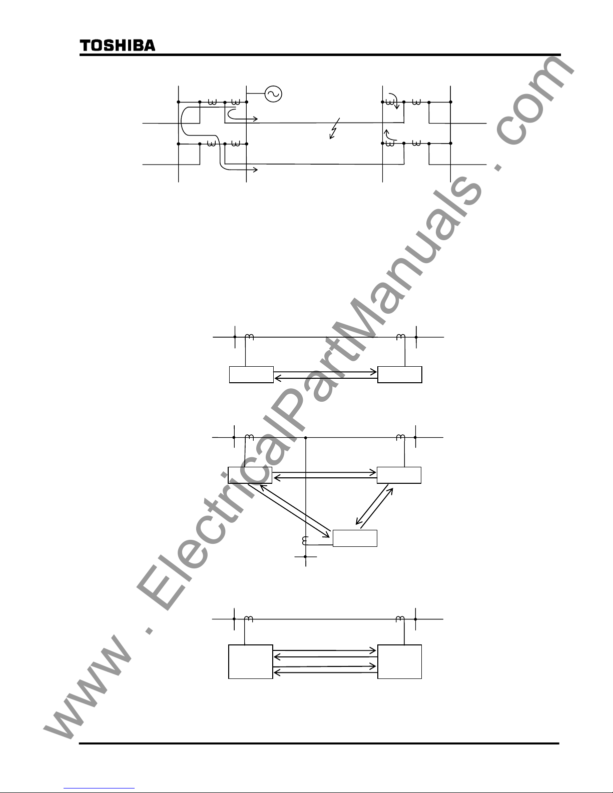
2.2.13 Communication System
2.2.13.1 Signaling Channel
The GRL100 transmits all the local data to the remote terminal by coded serial messages. Two
signaling channels are required for two-terminal line protection, six for three-terminal line
protection and four for dual communication for two-terminal line as shown in Figure 2.2.13.1.
GRL100
Terminal B Terminal A
GRL100
(a) Two-terminal Line
GRL100
GRL100
Terminal B
Terminal A
Terminal C
GRL100
(b) Three-terminal Line
Terminal B Terminal A
GRL100
GRL100
(c) Dual Communication for Two-terminal Line
Figure 2.2.13.1 Signaling Channel
F
Terminal B Terminal A
www . ElectricalPartManuals . com

30
6 F 2 S 0 8 5 0
The variation of the channel delay time due to switching the route of the channel is automatically
corrected in the relay and does not influence the synchronized sampling provided the sending
and receiving channels take the same route. If the routes are separate, the transmission delay
difference time must be set (see Section 2.2.7).
When the route is switched in A- or B-mode application, the synchronized sampling recovers
within 4s in case of a two- terminal line and 6s in case of a three-terminal line after the switching.
The differential element is blocked until the sampling synchronization is established.
In GPS-mode application (GPS-based synchronization), the sampling synchronization is not
influenced by the route switch. The differential element is only blocked for the duration of the
path switching.
2.2.13.2 Linking to Communication Circuit
The GRL100 can be provided with one of the following interfaces by order type and linked to a
dedicated optical fiber communication circuit or multiplexed communication circuit.
• Optical interface (1310nm, SM, 30km class)
• Optical interface (1550nm, DSF(Dispersion Shifted Fibre), 80km class) (*)
• Optical interface (820nm, GI, 2km class)
• Electrical interface in accordance with CCITT-G703-1.2.1
• Electrical interface in accordance with CCITT-G703-1.2.2 and 1.2.3
• Electrical interface in accordance with CCITT X.21
• Electrical interface in accordance with RS422, RS530
Note (*): When using the 80km class optical interface, it is necessary to ensure that the received
optical power does not exceed −10dB, in order to avoid communication failure due to
overloading of the receiver.
When testing in loop-back mode, for instance, the sending terminal should be
connected to the receiving terminal via an optical attenuator with 10 dB or more
attention.
Even if the sending terminal is directly connected to the receiving terminal, the optical
transceiver will not damaged, but communication failures may occur.
- Fibre Coupled Power: −5 to 0dBm
- Input Power Range: −34 to −10dBm
- Optical Damage Input Level: 3dBm
Alternative links to the telecommunication circuit are shown in Figure 2.2.13.2 (a) to (c).
www . ElectricalPartManuals . com

31
6 F 2 S 0 8 5 0
(a) Direct link
(b) Electrical link via multiplexer
(c) Optical link via multiplexer
Figure 2.2.13.2 Link to Communication Circuit
Direct link
When connected to single-mode (SM) 10/125µm type of dedicated optical fiber communication
circuits and using Duplex LC type connector for 30km class, the optical transmitter is an LD
with output power of more
than –13dBm and the optical receiver is a PIN diode with a sensitivity
of less than –30dBm. For 80km class, the optical transmitter is an LD with output power of more
than –5dBm and the optical receiver is a PIN diode with a sensitivity of less than –34dBm.
When connected to graded-index (GI) multi-mode 50/125µm type or 62.5/125µm type of
dedicated optical fiber telecommunication circuit and using an ST type connector, the optical
transmitter is an LED with output power of more
than –19dBm or –16dBm and the optical
receiver is a PIN diode with a sensitivity of less than –24dBm.
For details, refer to Appendix K.
Link via multiplexer
The GRL100 can be linked to a multiplexed communication circuit with an electrical or optical
interface. The electrical interface supports CCITT G703-1.2.1, G703-1.2.2 and 1.2.3,
X.21(RS530) or RS422. Twisted pair cable with shield (<60m) is used for connecting the relay
and multiplexer.
In the optical interface, optical fibers of graded-index multi-mode 50/125µm or 62.5/125µm
type are used and an optical to electrical converter is provided at the end of the multiplexer. The
electrical interface between the converter and the multiplexer supports CCITT G703-1.2.1,
G703-1.2.2 and 1.2.3, X.21(RS530) or RS422.
A D-sub connector (DB-25) or an ST connector is used for electrical linking and optical linking,
respectively.
O/E: Optical/Electrical converter
MUX: Multiplexer
Optical interface
GRL100
Twisted pair cable
with shield
< 60m
MUX
Optical
fibers
O/E
GRL100
Multiplexed circuit
Twisted pair cable with shield
< 60m
MUX
Electrical interface
GRL100
Optical fiber circuit
Optical interface
www . ElectricalPartManuals . com

32
6 F 2 S 0 8 5 0
2.2.13.3 Setup of Communication Circuit
The GRL100 is provided with one set of transmit and receive signal terminals for two-terminal
application models and two sets of signal terminals for three-terminal application models.
In case of two-terminal applications, the communication circuit is set as shown in Figure
2.2.13.3. In the figure, TX and RX are the transmit and receive signal terminals. CK is the
receive terminal for the multiplexer clock signal and is used when the interface supports CCITT
G703-1.2.2, 1.2.3 and X.21(RS530).
Terminal B
Terminal A
GRL100GRL100
TX1
TX1
RX1 RX1
(a) Direct Link Using Optical Fiber
Terminal B Terminal A
MUX: Multiplexer
O/E: Optical interface unit
GRL100GRL100
M
U
X
M
U
X
TX1
TX1
RX1
RX1
O/E
O/E
(b) Link via Multiplexer (Optical Interface)
CH1 CH1
CH1
CH1
Terminal B
Terminal A
GRL100
GRL100
M
U
X
M
U
X
TX1
RX1
CK1
Shield
ground
12
25
11
24
10
23
9
22
8
21
7
20
13
TX1
RX1
CK1
Shield
ground
(c) Link via Multiplexer (Electrical Interface
in accordance with CCITT-G703)
P
N
P
N
P
N
P
N
P
N
P
N
CH1 CH1
12
25
11
24
10
23
9
22
8
21
7
20
13
Terminal B
Terminal A
GRL100
GRL100
M
U
X
M
U
X
TX1
RX1
CK1
Shield
ground
12
25
11
24
10
23
9
22
8
21
7
20
13
TX1
RX1
CK1
Shield
ground
M
U
X
M
U
X
TX2
RX2
CK2
6
19
5
18
4
17
3
16
2
15
1
14
TX2
RX2
CK2
(d) Link via Multiplexer for Dual communication
(Electrical Interface in accordance with CCITT-G703)
P
N
P
N
P
N
P
N
P
N
P
N
P
N
P
N
P
N
P
N
P
N
P
N
CH1
CH1
CH2
CH2
12
25
11
24
10
23
9
22
8
21
7
20
13
6
19
5
18
4
17
3
16
2
15
1
14
Figure 2.2.13.3 Communication Circuit Setup in Two-terminal Application
www . ElectricalPartManuals . com

33
6 F 2 S 0 8 5 0
Terminal B
Terminal A
GRL100
GRL100
M
U
X
M
U
X
Signal ground
TX1
RX1
CK1
Shield
7
2
14
3
16
15
12
1
Signal ground
TX1
RX1
CK1
Shield
(e) Link via Multiplexer (Electrical Interface
in accordance with X.21, RS530)
Terminal B
Terminal A
GRL100
GRL100
(f) Link via Multiplexer for Dual communication
(Electrical Interface in accordance with X.21, RS530)
P
N
P
N
P
N
P
N
P
N
P
N
CH1 CH1
7
2
14
3
16
15
12
1
M
U
X
M
U
X
Signal ground
TX1
RX1
CK1
Shield
7
2
14
3
16
15
12
1
Signal ground
TX1
RX1
CK1
Shield
P
N
P
N
P
N
P
N
P
N
P
N
CH1 CH1
7
2
14
3
16
15
12
1
M
U
X
M
U
X
Signal ground
TX2
RX2
CK2
Shield
7
2
14
3
16
15
12
1
Signal ground
TX2
RX2
CK2
Shield
P
N
P
N
P
N
P
N
P
N
P
N
CH2 CH2
7
2
14
3
16
15
12
1
Figure 2.2.13.3 Communication Circuit Setup in Two-terminal Application (continued)
In case of three-terminal applications, signal terminals CH1-TX1, -RX1 and -CK1 which have
the same function as CH2-TX2, -RX2 and -CK2 are added.
Figure 2.2.13.4 shows the communication circuit arrangement for three-terminal applications.
Note that the CH1 signal terminals TX1, RX1 and CK1 of one terminal are interlinked with the
CH2 signal terminals TX2, RX2 and CK2 of another terminal and that the scheme switch
[TERM] is set to "3-TERM". If the same channel is interlinked between both terminals such as
the CH1 signal terminals of one terminal are interlinked with the CH1 signal terminals of another
terminal, the scheme switch setting [CH. CON] should be set to “Exchange”.
The three-terminal line application models can be applied to a two-terminal line. In this case,
same channel’s TX, RX and CK of both terminals are interlinked and scheme switch [TERM] is
set to "2-TERM".
The three-terminal models also have dual communication mode as shown in Figure 2.2.13.5.
www . ElectricalPartManuals . com

34
6 F 2 S 0 8 5 0
Terminal B
GRL100
Terminal A
GRL100
TX1
RX1
CK1
TX2
RX2
CK2
Terminal C
GRL100
CH1
CH1
CH2
CH2
TX2
RX2
CK2
CH2
TX1
RX1
CK1
CH1
TX1
RX1
CK1
TX2
RX2
CK2
Figure 2.2.13.4 Communication Circuit Setup for Three-terminal Applications
Terminal B
GRL100
Terminal A
GRL100
TX1
RX1
CK1
TX1
RX1
CK1
CH1
CH1
TX2
RX2
CK2
CH2
TX2
RX2
CK2
CH2
Note: The corresponding channels are connected to each other.
Figure 2.2.13.5 Dual Communication Mode
2.2.13.4 Telecommunication Channel Monitoring
If a failure occurs or noise causes a disturbance in the telecommunication channel, this may
interrupt the data transmission or generate erroneous data, thus causing the relay to operate
incorrectly.
The GRL100 detects data failures by performing a cyclic redundancy check and a fixed bit check
on the data. The checks are carried out for every sample.
If the failure lasts for ten seconds, a communication failure alarm is issued.
The output blocking ceases instantly when the failure recovers.
www . ElectricalPartManuals . com

35
6 F 2 S 0 8 5 0
2.2.14 Setting
The following shows the setting elements necessary for the current differential protection and
their setting ranges. The settings can be made on the LCD screen or PC screen.
Element Range Step Default Remarks Communication Mode
A B GPS
DIF Phase current
DIFI1
0.50 − 10.00A
0.01A 5.00A Small current region x x x
(0.10 − 2.00A
0.01A 1.00A)(*1)
DIFI2
3.0 − 120.0A
0.1A 15.0A Large current region x x x
(0.6 − 24.0A
0.1A 3.0A)
DIFG Residual current
DIFGI
0.25 − 5.00A
0.01A 2.50A x x x
(0.05 − 1.00A
0.01A 0.50A)
DIFIC
0.00 − 5.00A
0.01A 0.00 A x x x
(0.00 − 1.00A
0.01A 0.00 A)
Charging current compensation
Vn 100 - 120V 1V 110V Rated line voltage x x x
TDIFG
0.00 − 10.00s
0.01s 0.50s Delayed tripping timer x x x
DIFSV
0.25 − 10.00A
0.01A 0.50A x x x
(0.05 − 2.00A
0.01A 0.10A)
Differential current (Id) monitoring
TIDSV 0 – 60s 1s 10s Timer for Id detection x x x
OCCHK (*4)
0.5 − 5.0A
0.1A 0.5A -- -- x
(0.10 − 1.00A
0.01A 0.10A)
Minimum current for phase difference
check
HYSθ (*4) 1 − 5 deg
1 deg 1 deg Phase difference check margin -- -- x
TDSV 100 - 16000
1
µs 6000µs
Transmission delay time threshold
setting for alarm (*7)
x x x
TCDT1
−10000 − 10000 1µs 0µs
Transmission delay time difference
setting for channel 1 (*6)
x x x
TCDT2
−10000 − 10000 1µs 0µs
Transmission delay time difference
setting for channel 2 (*6)
x x x
PDTD
200 - 2000
µs 1µs 1000µs
Transmission delay time difference
between send and receive channels
(GPS synchronization only)
-- -- x
RYID 0-63 0 Local relay address
-- x x
RYID1 0-63 0 Remote 1 relay address
-- x x
RYID2 0-63 0 Remote 2 relay address
-- x x
[DIFG] ON/OFF ON High impedance earth fault protection x x x
[STUB] ON/OFF ON Measure for stub fault x x x
[RDIF] ON/OFF ON Remote differential protection -- x x
[OTD] ON/OFF OFF Open terminal detection x x x
[DIF-FS] OFF/OC/OCD/Both OFF Fail-safe function x x x
[DIFG-FS] ON/OFF OFF Fail-safe function x x x
[COMMODE] A / B / GPS B Communication mode A B GPS
[TERM] 2TERM/3TERM
/Dual (*2)
3TERM For three-terminal application models x x x
www . ElectricalPartManuals . com

36
6 F 2 S 0 8 5 0
Element Range Step Default Remarks Communication Mode
A B GPS
[SP.SYN] Master/Slave Master(*3) Sampling synchronization x x x
[CH. CON] Normal/Exchange Normal Telecommunication port exchanger x x x
[T.SFT1] ON/OFF OFF Channel 1 bit shifting for multiplexer x x x
[T.SFT2] ON/OFF OFF Channel 2 bit shifting for multiplexer x x x
[B.SYN1] ON/OFF ON Channel 1 bit synchronising for
multiplexer
x x x
[B.SYN2] ON/OFF ON Channel 2 bit synchronising for
multiplexer
x x x
[LSSV] ON/OFF OFF Disconnector contacts discrepancy
check
x x x
[GPSBAK] OFF/ON ON Backup synchronization -- -- x
[AUTO2B](*6) OFF/ON OFF Automatic mode change -- -- x
[SRCθ](*5)
Disable / I I Sampling timing deviation monitoring
with current
-- -- x
[IDSV] OFF/ALM&BLK/ALM OFF Id monitoring x x x
[RYIDSV] OFF/ON ON Relay address monitoring -- x x
(*1) Current values shown in parentheses are in the case of 1A rating. Other current values are in the
case of 5A rating.
(*2) This setting is valid for three-terminal application models of the GRL100.
(*3) In the actual setting, one terminal is set to "Master" and other terminal(s) to "Slave".
(*4) OCCHK, [SRCθ] and HYSθ are enabled by setting the [TERM] to "2TERM".
(*5) [AUTO2B] is enabled by setting the [TERM] to "2TERM" and [SRCθ] to "I".
(*6) This setting is only used when there is a fixed difference between the sending and receiving
transmission delay time. When the delay times are equal, the default setting of 0µs must be
used.
(*7) If the channel delay time of CH1 or CH2 exceeds the TDSV setting, then the alarm "Td1 over"
or "Td2 over" is given respectively.
CT Ratio matching
When the CT ratio is different between the local terminal and the remote terminal(s), the CT
ratio matching can be done as follows:
The differential element settings are respectively set to the setting values so that the primary fault
detecting current is the same value at all terminals. Figure 2.2.14.1 shows an example of CT ratio
matching. The settings for DIFI2, DIFGI, DIFSV and DIFIC should also be set with relation to
the primary current in the same manner of the DIFI1 setting.
CT ratio : 2000/1A
Terminal-A
Terminal-B
GRL100
GRL100
DIFI1=800A / CT ratio(2000/1A)
= 0.4A
CT ratio : 4000/1A
DIFI1=800A / CT ratio(4000/1A)
= 0.2A
Primary sensitivity = 800A
Figure 2.2.14.1 Example of CT Ratio Matching
www . ElectricalPartManuals . com

37
6 F 2 S 0 8 5 0
If the CT secondary ratings at the local and remote terminals are different, relay model suitable
for the CT secondary rating is used at each terminal and then CT ratio matching can be applied
the same as above. The differential element settings are respectively set to the setting values so
that the primary fault detecting current is the same value at all terminals. Figure 2.2.14.2 shows
an example of CT ratio matching. The settings for DIFI2, DIFGI, DIFSV and DIFC should also
be set with relation to the primary current in the same manner of the DIFI1 setting.
CT ratio : 2000/1A
Terminal-A
Terminal-B
GRL100
1A rated model
DIFI1=800A / CT ratio(2000/1A)
= 0.4A
CT ratio : 2000/5A
DIFI1=800A / CT ratio(2000/5A)
= 2.0A
Primary sensitivity = 800A
GRL100
5A rated model
Figure 2.2.14.2 Example of CT Ratio Matching incase of Different CT secondary Rating
Setting of DIFI1
The setting of DIFI1 is determined from the minimum internal fault current to operate and the
maximum erroneous differential current (mainly the internal charging current) during normal
service condition not to operate.
DIFI1 should therefore be set to satisfy the following equation:
K⋅Ic < DIFI1 < I
f
/ K
where,
K: Setting margin (K = 1.2 to 1.5)
Ic: Internal charging current
If: Minimum internal fault current
For the GRL100 provided with the charging current compensation, the condition related to the
charging current can be neglected.
The setting value of DIFI1 must be identical at all terminals. If the terminals have different CT
ratios, then the settings for DIFI1 must be selected such that the primary settings are identical.
Setting of DIFI2
The setting of DIFI2 is determined from the following two factors:
• Maximum erroneous current generated by CT saturation in case of an external fault
• Maximum load current
• Maximum outflow current in case of an internal fault
In the first factor, the DIFI2 should be set as small as possible so that unwanted operation is not
caused by the maximum erroneous current generated by CT saturation on the primary side by a
through current at an external fault. It is recommended normally to set DIFI2 to 2×In (In:
secondary rated current) for this factor.
In the second factor, the DIFI2 should be set large enough such that it does not encroach on load
current.
The third factor must be considered only when the GRL100 is applied to three-terminal
www . ElectricalPartManuals . com

38
6 F 2 S 0 8 5 0
double-circuit lines, lines with outer loop circuit, or double-circuit lines with one-and-a-half
busbar system. DIFI2 should be set larger than the possible largest value of outflow current in
case of an internal fault.
As the occurrence of current outflow depends on the power system configuration or operation, it
is necessary to check whether it is possible for the fault current to flow out of the line. If so, the
factor must be taken into consideration when making the setting.
In other applications, only the first and second factors need be considered.
Setting of DIFGI
The setting of DIFGI is determined from the high-impedance earth fault current.
The setting value of DIFGI must be identical at all terminals. If the terminals have different CT
ratios, then the settings for DIFGI must be selected such that the primary settings are identical.
Setting of DIFSV
When using the differential current monitoring function, the setting of DIFSV is determined
from the maximum erroneous differential current during normal service condition.
K⋅Ierr < DIFSV < DIFI1 / (1.5 to 2)
Ierr: maximum erroneous differential current
For the GRL100 provided with the charging current compensation, the condition related to the
charging current can be neglected.
The setting value of DIFSV must be identical at all terminals. If the terminals have different CT
ratios, then the settings for DIFSV must be selected such that the primary settings are identical.
Setting of DIFIC
The internal charging current under the rated power system voltage is set for DIFIC. The
charging current is measured by energizing the protected line from one terminal and opening the
other terminal.
If the measured power system voltage differs from the rated one, the measured charging current
must be corrected.
The setting value of DIFIC must be identical at all terminals. If the terminals have different CT
ratios, then the settings for DIFIC must be selected such that the primary settings are identical.
Setting of OCCHK
This setting is available for [COMMODE]=‘GPS-MODE’ setting. The OCCHK must be set
larger than any of the following three values, taking the errors due to charging current and
measurement inaccuracy into consideration. If the differential current setting in the small current
region DIFI1 differs between terminals due to different CT ratios, the larger DIFI1 is applied.
• 14 × charging current (A)
• 0.5 × DIFI1 setting (A)
• 0.5A (or 0.1A in case of 1A rating)
Setting of PDTD, [COMMODE], [GPSBAK], [AUTO2B], [TERM], [SRC θ] and [RYIDSV]
The setting of these items must be identical at all terminals.
COMMODE: generally set to ‘B-MODE’ which is standard operating mode. Set to ‘A-MODE’
if the opposite terminal relay is an old version of GRL100, that is GRL100-∗∗∗A,
-∗∗∗N or -∗∗∗Y. If the relay is applied to the GPS-based synchronization, set to
www . ElectricalPartManuals . com

39
6 F 2 S 0 8 5 0
‘GPS-MODE’. The ‘GPS-MODE’ is only available for the relay provided with a
GPS interface.
PDTD, GPSBAK, AUTO2B, SRCθ : Available for [COMMODE]=‘GPS-MODE’ setting. See
Section 2.2.7.
Note: Do not set [TERM] to “Dual” in GPS-mode.
Setting of TDSV, TCDT1 and TCDT2
The TDSV is a transmission delay time threshold setting. GRL100 gives an alarm if the
transmission delay time exceeds TDSV. The alarm messages are ‘Td1 over’ for CH1 and ‘Td2
over’ for CH2.
The TCDT1 and TCDT2 are transmission time delay difference settings for CH1 and CH2
respectively. If there is a permanent and constant difference of more than 100µs between the
send and receive channel delay times, then the TCDT setting is used to compensate for that
difference. The setting is calculated as follows:
TCDT = (Sending delay time) − (Receiving delay time)
(Example)
RELAY A
RELAY B RELAY C
CH1
CH1
CH1
CH2
CH2
CH2
1000µs
1000µs
2000µs
1000µs
3000µs
5000µs
Setting of [SP.SYN]
One of terminals must be set to MASTER and others SLAVE.
If not, the synchronized sampling fails under the intra-system synchronized sampling or backup
modes of the GPS-based synchronized sampling.
Note: As the simultaneous setting change at all terminals is not practical, it is not recommended to
change the settings when the relay is in service.
Setting of [CH.CON]
In case of the two-terminal line application, the communication ports of the GRL100 are
interlinked with port CH1 as shown in Figure 2.2.14.3(a) and (b). In case of three-terminal
application, port CH1 of one terminal and port CH2 of the other terminal are linked as shown in
Figure 2.2.14.3(c).
In these normal linkages, the communication port exchange switch [CH.CON] is set to
"Normal".
Setting of [T.SFT1], [T.SFT2], [B.SYN1], and [B.SYN2]
T.SFT1: is used to synchronise the relay with multiplexer by shifting the send signal by a half-bit
when the distance from the relay to the multiplexer is long. When electrical interface
X.21, CCITT G.703-1.2.2 or -1.2.3 is applied and the distance (cable length from relay to
multiplexer) is 300m or more, the setting is set to 'ON'. (for channel 1)
T.SFT2: same as above. (for channel 2)
CH1: TCDT1 = 2000 − 1000
= 1000
µs
CH2: TCDT2 = 1000 − 1000
= 0
µs
CH1: TCDT1 = 5000 − 3000
= 2000
µs
CH2: TCDT2 = 1000 − 2000
= −1000
µ
s
CH1: TCDT1 = 1000 − 1000
= 0
µs
CH2: TCDT2 = 3000 − 5000
= −2000
µs
www . ElectricalPartManuals . com

40
6 F 2 S 0 8 5 0
B.SYN1: is set to 'ON' when the relay is linked via multiplexer, and set to 'OFF' when direct link
is applied. (for channel 1)
This setting is available for CCITT G703-1.2.1, 1.2.2, 1.2.3, X21 and optical interface
(short distance: 2km class). In the case of optical interface 30km and 80km class, this
setting is neglected.
B.SYN2: same as above. (for channel 2)
Setting of RYID, RYID1 and RYID2
Relay address number RYID must take a different number at each terminal.
If the relay address monitoring switch [RYIDSV] is "OFF", their settings are ignored. The
RYID2 setting is enabled by setting the [TERM] to "3TERM" or "Dual".
Two-terminal application: Set the local relay address number to RYID and the remote relay
address number to RYID1. The RYID1 is equal to the RYID of the
remote relay. See Figure 2.2.14.3.
In “Dual” setting, the RYID2 setting must be the same as the RYID1
setting.
Three-terminal application: Set the local relay address number to RYID and the remote relay 1
address number to RYID1 and the remote relay 2 address number to
RYID2. The RYID1 is equal to the RYID of the remote 1 relay and
the RYID2 equal to the RYID of the remote 2 relay. See Figure
2.2.14.3.
Note: The remote 1 relay is connected by CH1 and the remote 2 relay connected by CH2
Terminal B
CH1
CH2
Communication port
CH1
CH2
Terminal A
(a) Two-terminal Application
RYID=1
RYID1=0
RYID=0
RYID1=1
Terminal B
CH1
CH2
CH1
CH2
Terminal A
(b) Two-terminal Application (Dual)
RYID=1
RYID1=0
RYID2=0
RYID=0
RYID1=1
RYID2=1
Terminal B Terminal A
Terminal C
CH1
CH2
CH2
CH1
CH1
CH2
RYID=2
RYID1=0
RYID2=1
RYID=0
RYID1=1
RYID2=2
RYID=1
RYID1=2
RYID2=0
(c) Three-terminal Application
Figure 2.2.14.3 Communication Link in Three-terminal Line
www . ElectricalPartManuals . com

41
6 F 2 S 0 8 5 0
Setting depending on communication mode
The setting depending on communication mode is shown in the following table.
Setting A-MODE B-MODE GPS-MODE Default setting Remarks
Communication
mode
COMMODE Must select “A” of
A/B/GPS
Must select “B” of
A/B/GPS
Must select “GPS”
of A/B/GPS
B
GPS backup
mode
GPSBAK -- -- On/Off On
MODE2B shifted
automatically
AUTO2B -- -- On/Off Off
Phase difference
check
SRCθ -- -- Disable/I I Available for only
2TERM setting
Terminal
application
TERM 2TERM/3TERM/
DUAL
2TERM/3TERM/
DUAL
2TERM/3TERM 2TERM For 3 terminal
application model
Relay address
monitoring
RYIDSV -- On/Off On/Off On
Multi-phase
autoreclosing
Autoreclose
mode
MPAR2/MPAR3 MPAR2/MPAR3 MPAR2/MPAR3 SPAR&TPAR RYIDSV=Off is
required
Open terminal
detection
OTD On/Off On/Off On/Off Off
Zero-phase
current differential
DIFG On/Off On/Off On/Off On
Out-of-step
tripping
OST Trip/BO/Off Trip/BO/Off Trip/BO/Off Off
Fault locator FL On/Off On/Off On/Off On
Remote
differential trip
RDIF -- On/Off On/Off On Available for 3TERM
application
--: don’t care.
Terminal application
In A-MODE and B-MODE, anyone of 2TERM, 3TERM or DUAL can be selected. In
GPS-MODE, however, DUAL cannot be selected.
Multi-phase autoreclosing
To apply the multi-phase autoreclosing with MPAR2 or MPAR3, the relay address monitoring
RYIDSV in B-MODE and GPS-MODE must be set to “OFF”. When the RYIDSV=OFF, CBLS
(CBDS) condition is sent.
If shared with the relay address monitoring, the bits for CBLS condition can be assigned instead
of the bits for DIFG or OST/FL by PLC function when DIFG or OST/FL is not used.
Automatic open terminal detection OTD
In B-MODE and GPS-MODE, the RYIDSV=OFF setting for relay address monitoring is
required to use the open terminal detection function (OTD=On).
If shared with the relay address monitoring, the following methods can be applied:
(1) Only one bit with open terminal condition instead of CBLS condition can be sent by
sub-communication bit.
(2) If DIFG or OST/FL is not used, the bits for CBLS condition can be assigned instead of the
bits for DIFG or OST/FL by PLC function.
The open terminal detection in B-MODE and GPS-MODE do not automatically change
www . ElectricalPartManuals . com

42
6 F 2 S 0 8 5 0
“Master” or Slave” in SP.SYN. If the master terminal becomes out-of-service, therefore, the
synchronization control of slave terminal follows that of the master terminal by ON/OFF at the
master terminal and the current differential protection is blocked.
When putting a terminal into out-of-service in three-terminal operation, the following setting
change method is recommended:
(Example)
When putting Terminal C into out-of-service to two-terminal operation, the following four
setting are changed.
SP.SYN:
If the terminal C has been “Master”, change the terminal A or B to “Master”. If the terminal A or
C has been “Master”, do not change the setting.
TERM:
Change both the terminal A and B to “2TERM”.
CH.CON:
It is defined that CH1 of both terminal relays is connected each other in two-terminal application
and CH1 of local relay is connected to CH2 of remote relay in three-terminal application as
shown in Figure 2.2.14.3. Therefore, the communication cable connection must be changed from
CH2 to CH1.
[CH.CON] is to change CH1 or CH2 signal with CH2 or CH1 signal in the relay inside. If the
[CH.CON] is set to “Exchange”, CH2 data is dealt with as CH1 data or in reverse. In Figure
2.2.14.3, change the terminal B to “Exchange”. However, note that the display or output such as
a communication failure, etc. is expressed as CH1 because CH2 data is dealt with as CH1 data at
the terminal B.
RYID1:
The remote terminal 1 seen from terminal B changes from terminal C to terminal A. Therefore,
change the remote terminal 1 relay address setting RYID1 from "2" to "0" at terminal B.
If the relay address monitoring switch [RYIDSV] is "OFF", the setting is invalid and setting
change is not required.
Remote differential trip RDIF
This function is not available for the A-MODE setting.
When this function is used, set [RDIF] and [TERM] are set to "ON" and "3-TERM" and the
following must be configured by the PLC function.
Assign the remote DIF trip send signals RDIF-∗-S to user configurable data, and the receiving
data from remote terminals to the trip command signals RDIF-∗-R1 and RDIF-∗-R2.
www . ElectricalPartManuals . com

43
6 F 2 S 0 8 5 0
2.3 Distance Protection
2.3.1 Time-Stepped Distance Protection
2.3.1.1 Application
Using reach and tripping time settings coordinated with adjacent lines, the GRL100 provides three
steps of distance protection for forward faults and one backup protection for reverse faults. These
are used as the main protection when telecommunications are not available, or as backup
protection for the protected line and adjacent lines.
The GRL100 has four distance measuring zones for both phase and earth faults, three zones for
forward faults and one zone for reverse faults respectively. The zones can be defined with either
mho-based characteristic or quadrilateral characteristic. The characteristic is selected by setting
the scheme switch [ZS-C] for phase fault and [ZG-C] for earth fault to "Mho" or "Quad".
Figure 2.3.1.1 shows the mho-based characteristics. Zone 1 (Z1) and Zone 2 (Z2) have a complex
characteristic combining the reactance element, mho element and blinder element, while Zone 3
(Z3), reverse Zone R (ZR) and reverse Zone 4 (Z4) elements have a complex characteristic
combining the mho element and blinder element.
The blinder element (BFR) can be provided for each forward zone. The setting of blinder element
can be set independently or set common to forward zones by the scheme switch [BLZONE].
Figures 2.3.1.1 and 2.3.1.2 show the characteristics with an independent setting.
Since the Z4 is used for detection of reverse faults in command protection, the Z4 for phase faults
has an offset characteristic with an offset mho element which assures detection of close-up phase
faults. The operation of Z4 for phase faults in the event of internal faults is inhibited by the
operations of Z2 and Z3.
Figure 2.3.1.2 shows the quadrilateral characteristics. These have a complex characteristic
combining the reactance element, directional element and blinder element.
The Z4 for phase faults has an offset characteristic with an offset directional element which
assures detection of close-up phase faults.
The operation is the same as the mho-based characteristics.
Z1S
Z2S
Z3S
Z4S
BFR1S
BRRS
Z1G
Z2G
Z3G
Z4G
BFR1G
BRRG
Z3Sθ
Z1Sθ1
75°
Z3G
θ
Z1Gθ1
75°
ZRS
ZRG
BRLS
BFR2S
BFRS
BFR2G
BFRG
BRLG
(a) Phase fault element (b) Earth fault element
Figure 2.3.1.1 Mho-based Characteristics
www . ElectricalPartManuals . com

44
6 F 2 S 0 8 5 0
Z1G
Z2G
Z3G
Z4G
BFR1G
BRRG
Z1S
Z2S
Z3S
Z4S
BFR1S
BRRS
ZRS
ZRG
BFR2S
BFRS
BRLS
BFR2G
BFRG
BRLG
(a) Phase fault element (b) Earth fault element
Figure 2.3.1.2 Quadrilateral Characteristics
Figure 2.3.1.3 shows typical time-distance characteristics of the time-stepped distance protection
provided at terminal A.
Zone 1 is set to cover about 80% of the protected line. When GRL100 is used as the main
protection, zone 1 generally provides instantaneous tripping but if used as a backup protection,
time delayed tripping can be provided. With the GRL100, 6 types of zone 1 tripping modes can be
set using the trip mode setting switch [Z1CNT].
Zone 2 is set to cover about 120% or more of the protected line, providing protection for the rest of
the protected line not covered by zone 1 and backup protection of the remote end busbar. In order
to coordinate the fault clearance time by the main protection, with the zone 1 protection of the
adjacent lines or by the remote end busbar protection, zone 2 carries out time delayed tripping.
Zone 2 trip can be disabled by the scheme switch [Z2TP].
Time
TR
T3
T2
T1
C BA
Reverse Zone R
Zone 2
Zone 1
Zone 3
∼
∼
Figure 2.3.1.3 Time/Distance Characteristics of Time-Stepped Distance Protection
Zone 3 is mainly provided for remote backup protection of adjacent lines. Its reach is set to at least
1.2 times the sum of the impedance of the protected line and the longest adjacent line. The zone 3
time delay is set so that it coordinates with the fault clearance time provided by zone 2 of adjacent
lines.
The reverse looking zone R element is used for time delayed local backup protection for busbar
faults and transformer faults. Furthermore, when applied to multi-terminal lines, it is effective as
the backup protection for adjacent lines behind the relaying point instead of the zone 3 protection
www . ElectricalPartManuals . com

45
6 F 2 S 0 8 5 0
at the remote terminal. This is because it is difficult for zone 3 at terminals A and C to provide
remote backup protection for the fault shown in Figure 2.3.1.4 due to fault infeed from the other
terminal, whereas reverse looking zone R of terminal B is not affected by this. Zone R trip can be
disabled by the scheme switch [ZRTP].
Zone 3
Zone R
A
C
B
Figure 2.3.1.4 Reverse Zone Protection
To maintain stable operation for close-up three-phase faults which cause the voltages of all phases
to drop to 0 or close to 0, zone 1 for phase faults, once operated, changes its element to a reverse
offset element. This continues until the fault is cleared, and thus it is effective for time delayed
protection.
The reactance element characteristics of zone 1 and zone 2 are parallel lines to the R axis and
provide sufficient coverage for high-resistance faults. The reactance element characteristics of
zone 1 can be transformed to a broken line depending on the load flow direction in order to avoid
overreaching by the influence of load current. The characteristic in the resistive direction is limited
by the mho characteristic of zone 3. The reactive reach setting is independent for each zone. It is
also possible to have independent settings for each individual phase fault and earth fault elements.
With a long-distance line or heavily loaded line, it is possible for the load impedance to encroach
on the operation zone of the mho element. Blinders are provided to limit the operation of the mho
element in the load impedance area.
Zero-sequence current compensation is applied to zone 1 and zone 2 for earth fault protection.
This compensates measuring errors caused by the earth return of zero-sequence current. This
allows the faulted phase reactance element to precisely measure the positive-sequence impedance
up to the fault point. Furthermore, in the case of double-circuit lines, zero-sequence current from
the parallel line is introduced to compensate for influences from zero-sequence mutual coupling.
Considering the case where the impedance angle of positive-sequence impedance and
zero-sequence impedance differ which is the most common in cable circuits, GRL100 carries out
vectorial zero-sequence current compensation.
The autoreclose schemes are utilised with instantaneous zone 1 tripping. When single-phase
autoreclose or single- and three-phase autoreclose are selected, zone 1 executes single-phase
tripping for a single-phase earth fault. In order to achieve reliable fault phase selection even for
faults on heavily loaded long-distance lines or irrespective of variations in power source
conditions behind the relaying point, an undervoltage element with current compensation is used
as a phase selector. Other zones only execute three-phase tripping, and do not initiate autoreclose.
2.3.1.2 Scheme Logic
Figure 2.3.1.5 shows the scheme logic for the time-stepped distance protection. For zone 1
tripping, as described later, it is possible to select instantaneous tripping or time delayed tripping
using the scheme switch [Z1CNT] in the trip mode control logic. (Detail of the [Z1CNT] is
described after.) Zone 2, zone 3 and zone R give time delayed tripping. However, these zones can
trip instantaneously by PLC signals Z∗_INST_TP. Timers TZ2, TZ3 and TZR with time delayed
tripping can be set for earth faults and phase faults separately. Zone 1, zone 2, zone 3 and zone R
www . ElectricalPartManuals . com

46
6 F 2 S 0 8 5 0
tripping can be disabled by the scheme switches [Z1CNT] and [Z∗TP].
Note: For the symbols used in the scheme logic, see Appendix L.
S-TRIP
&
Trip
mode
control
M-TRIP
TZ2G
t0
&
Z1G
Z2G
Phase
selection
logic
Sigle-phase
tripping
command
0.00 - 10.00s
[PSB-Z1]
PSBG_DET
+
[Z2TP]
[PSB-Z2]
NON VTF
Three-phase
tripping
command
TZ1G
t0
0.00 - 10.00s
&
Z1S
"ON"
[PSB-Z1]
TZ1S
t0
0.00 - 10.00s
Z2G_BLOCK
1890
TZ2S
t0
&
0.00 - 10.00s
"ON"
"ON"
Z2S
[PSB-Z2]
Z2S_BLOCK
1906
"ON"
≥
1
"ON"
TZ3G
t0
&
Z3G
0.00 - 10.00s
+
[Z3TP]
[PSB-Z3]
Z3G_BLOCK
1891
TZ3S
t0
&
0.00 - 10.00s
"ON"
Z3S
[PSB-Z3]
Z3S_BLOCK
1907
"ON"
"ON"
TZRG
t0
&
ZRG
0.00 - 10.00s
+
[ZRTP]
[PSB-ZR]
ZRG_BLOCK
1894
TZRS
t0
&
0.00 - 10.00s
"ON"
ZRS
[PSB-ZR]
ZRS_BLOCK
1910
"ON"
"ON"
PSBS_DET
circuit
Figure 2.3.1.5 Scheme Logic of Time-stepped Distance Protection
Tripping by each zone can be blocked the PLC signal Z∗∗_BLOCK. The tripping can be also
blocked in the event of a failure of the secondary circuit of the voltage transformer or power
swing. The former is detected by the VT failure detection function. The signal VTF becomes 1
when a failure is detected. The latter is detected by the power swing blocking function. The signal
PSB becomes 1 when power swing is detected. The zone in which tripping will be blocked during
a power swing can be set using the selection switches [PSB-Z1] to [PSB-ZR]. For the VTF and
PSB, see Section 2.3.3 and Section 3.3.5, respectively.
By using the trip mode control logic, Zone 1 can implement different trip modes. The trip modes
as shown in Table 2.3.1.1 can be selected according to the position of the scheme switch [Z1CNT]
and whether or not the differential protection is in or out of service.
www . ElectricalPartManuals . com

47
6 F 2 S 0 8 5 0
Table 2.3.1.1 Zone 1 Trip Mode Control
Z1CNT CURRENT DIFFERENTIAL PROTECTION USE OR NOT
Position USE NO USE (*)
1 SINGLE-PHASE TRIP & AUTO-REC SINGLE-PHASE INST. TRIP & AUTO-REC
2 THREE-PHASE TRIP SINGLE-PHASE INST. TRIP & AUTO-REC
3 THREE-PHASE TRIP THREE-PHASE INST. TRIP
4 SINGLE-PHASE TRIP & AUTO-REC
5 THREE-PHASE TRIP
6 Z1 TRIP BLOCK
(*): during a communication failure or when the [DIF] setting is “No use”.
The zone 1 tripping mode at each position of the switch [Z1CNT] is as follows:
Position 1: When the current differential protection is in service, zone 1 executes time tripping
with a time delay using timer TZ1 and starts autoreclose. Zone 1 performs single-phase tripping
and reclosing or three-phase tripping and reclosing depending on the reclose mode of the
autoreclose function and the type of faults (single-phase faults or multi-phase faults). If the
autoreclose is out of service, zone 1 performs three-phase final tripping for all faults.
When the current differential protection is out of service, zone 1 executes performs instantaneous
single-phase tripping and reclosing or three-phase tripping and reclosing depending on the reclose
mode of the autoreclose function and the type of faults (single-phase faults or multi-phase faults).
If the autoreclose is out of service, zone 1 performs instantaneous three-phase final tripping for all
faults.
Position 2: When the current differential protection is in service, zone 1 performs three-phase
tripping with a time delay using timer TZ1 and does not start autoreclose. The zone 1 performs
instantaneous single-phase tripping and reclosing or three-phase tripping and reclosing depending
on the reclose mode of the autoreclose function and the type of faults (single-phase faults or
multi-phase faults), if the current differential protection is out of service. If the autoreclose is out
of service, zone 1 performs three-phase final tripping for all faults.
Position 3: When the current differential protection is in service, zone 1 performs three-phase
tripping with a time delay using timer TZ1 and does not start autoreclose. The zone 1 performs
three-phase tripping instantaneously and does not start autoreclose if the current differential
protection is out of service.
Position 4: Though the current differential protection is in service or out of service, zone 1
executes time tripping with a time delay using timer TZ1 and starts autoreclose. Zone 1 performs
single-phase tripping and reclosing or three-phase tripping and reclosing depending on the reclose
mode of the autoreclose function and the type of faults (single-phase faults or multi-phase faults).
If the autoreclose is out of service, zone 1 performs three-phase final tripping for all faults.
Position 5: Though the current differential protection is in service or out of service, zone 1
performs three-phase tripping with a time delay using timer TZ1 and does not start autoreclose.
Position 6: Zone 1 tripping is blocked though the current differential protection is in service or out
of service.
Zone 1 Trip Mode Control is performed using PLC default function as shown in Figure 2.3.1.6. By
changing the PLC default setting, the Z1 trip can be controlled independently of the [Z1CNT]
setting.
www . ElectricalPartManuals . com

48
6 F 2 S 0 8 5 0
DIF_OUT_
SERV
Z1CNT_INST
+
43C ON
[Z1CNT]
Z1_INST_TP
1936
785
786
787
788
Z1CNT_3PTP
Z1CNT_ARCBLK
Z1CNT_TPBLK
Z1_3PTP
1968
Z1_ARC_BLOCK
1847
Z1G_BLOCK
1888
Z1S_BLOCK
1904
Z1 can trip instantaneously.
Z1 performs three-phase trip.
Z1 performs final tripping
for all faults.
Z1G trip is blocked.
Z1S trip is blocked.
Defalt setting
DIF_OUT
2015
Trip
Mode
Control
Logic
Zone 1
1
≥1
789
DIF BLOCK
Communication
failure, etc.
+
[DIF]
"OFF"
Defalt setting
From
Figure
2.2.2.1.
Figure 2.3.1.6 Zone 1 Trip Mode Control Circuit
If the distance protection is active only when communication failure in the GRL100, it is achieved
by the PLC function. See Appendix S.
Zone 1 tripping is provided with an additional phase selection element UVC and phase selection
logic to make sure the faulted phase is selected for the single-phase earth fault.
Figure 2.3.1.7 gives details of the phase selection logic in Figure 2.3.1.5. In case of single-phase
earth fault, the earth fault measuring zone 1 element Z1G with a certain phase and the phase
selection element UVC with the same phase operate together, and a single-phase tripping
command S-TRIP can be output to the phase.
&
UVC - C
UVC - B
UVC - A
Z1G - C
Z1G - B
Z1G - A
≥1
Z1S-BC
Z1S-AB
C
B
A
&
&
&
Z1S-CA
S-TRIP
M-TRIP
560
561
562
EFL
UVPWI-C
UVPWI-B
UVPWI-A
631
632
633
634
608
609
610
575
576
577
≥1
&
&
&
Z3G - C
Z3G - B
Z3G - A
566
567
568
≥1
&
&
&
Figure 2.3.1.7 Phase Selection Logic for Zone 1 Protection
Depending on the setting of the scheme switch [Z1CNT] or [ARC-M] which selects reclosing
mode, single-phase tripping may be converted to a three-phase tripping command. This is not
shown in the figure.
In case of multi-phase fault, the phase fault measuring zone 1 element Z1S and the two phases of
the UVC operate together, the Z1G trip is blocked and the three-phase tripping command M-TRIP
www . ElectricalPartManuals . com

49
6 F 2 S 0 8 5 0
is always output. The condition for the UVC two-phase operation is to inhibit the Z1S from
overreaching in the event of a single-phase earth fault.
The UVC element is applied to the zone 1 distance elements.
EFL is an earth fault detection element, and UVPWI is a phase undervoltage relay to provide
countermeasures for overreaching of a leading-phase distance element at positive phase weak
infeed condition. These elements are applied to all earth fault distance elements. (Refer to
Appendix A.) The UVPWI can be disabled by the scheme switch [UVPWIEN].
2.3.1.3 Setting
The following shows the necessary distance protection elements and their setting ranges.
Element Range Step Default Remarks
Phase fault protection
ZS-C Mho - Quad Mho Characteristic selection
Z1S
0.01 - 50.00Ω 0.01Ω 1.60Ω
Z1 reach
(0.10 - 250.00Ω 0.01Ω 8.00Ω) (*1)
Z1S θ1
0° - 45° 1° 0° Gradient of reactance element
Z1S θ2
45° - 90° 1° 90°
BFR1S
0.10 - 20.00Ω 0.01Ω 5.10Ω
Forward right blinder reach for Z1
(0.5 - 100.0Ω 0.1Ω 25.5Ω)
Z2S
0.01 - 50.00Ω 0.01Ω 3.00Ω
Z2 reach
(0.10 - 250.00Ω 0.01Ω 15.00Ω)
BFR2S
0.10 - 20.00Ω 0.01Ω 5.10Ω
Forward right blinder reach for Z2
(0.5 - 100.0Ω 0.1Ω 25.5Ω)
Z3S
0.01 - 50.00Ω 0.01Ω 6.00Ω
Z3 reach
(0.1 – 250.0Ω 0.1Ω 30.0Ω)
Z3S θ(*2)
45 - 90° 1° 85° Characteristic angle of mho element
ZBS θ(*3)
0 - 45° 1° 5° Angle of directional element
BFRS
0.10 - 20.00Ω 0.01Ω 5.10Ω
Forward right blinder reach for Z3
(0.5 - 100.0Ω 0.1Ω 25.5Ω)
BFLS θ
90° - 135° 1° 120° Forward left blinder angle
ZRS
0.01 - 50.00Ω 0.01Ω 4.00Ω
ZR reach
(0.1 – 250.0Ω 0.1Ω 20.0Ω)
Z4S
0.01 - 50.00Ω 0.01Ω 8.00Ω
Z4 reach
(0.1 – 250.0Ω 0.1Ω 40.0Ω)
BRRS
0.10 - 20.00Ω 0.01Ω 5.10Ω
Reverse right blinder reach
(0.5 - 100.0Ω 0.1Ω 25.5Ω)
TZ1S 0.00 - 10.00 s 0.01 s 0.00 s Zone 1 timer
TZ2S 0.00 - 10.00 s 0.01 s 0.30 s Zone 2 timer
TZ3S 0.00 - 10.00 s 0.01 s 0.40 s Zone 3 timer
TZRS 0.00 - 10.00 s 0.01 s 0.60 s Zone R timer
Earth fault protection
ZG-C Mho - Quad Mho Characteristic selection
Z1G
0.01 - 50.00Ω 0.01Ω 1.60Ω
Z1 reach
(0.10 - 250.00Ω 0.01Ω 8.00Ω)
Z1G θ1
0° - 45° 1° 0° Gradient of reactance element
Z1G θ2
45° - 90° 1° 90°
BFR1G
0.10 - 20.00Ω 0.01Ω 5.10Ω
Forward right blinder reach for Z1
(0.5 - 100.0Ω 0.1Ω 25.5Ω)
www . ElectricalPartManuals . com

50
6 F 2 S 0 8 5 0
Element Range Step Default Remarks
Z2G
0.01 - 50.00Ω 0.01Ω 4.00Ω
Z2 reach
(0.10 - 250.00Ω 0.01Ω 20.00Ω)
BFR2G
0.10 - 20.00Ω 0.01Ω 5.10Ω
Forward right blinder reach for Z2
(0.5 - 100.0Ω 0.1Ω 25.5Ω)
Z3G
0.01 - 100.00Ω 0.01Ω 8.00Ω
Z3 reach
(0.1 – 500.0Ω 0.1Ω 40.0Ω)
Z3G θ(*2)
45 - 90° 1° 85° Characteristic angle of mho element
ZBGθ(*3)
0° - 45° 1° 30° Angle of directional element
BFRG
0.10 - 20.00Ω 0.01Ω 5.10Ω
Forward right blinder reach for Z3
(0.5 - 100.0Ω 0.1Ω 25.5Ω)
BFLG θ
90° - 135° 1° 120° Forward left blinder angle
ZRG
0.01 - 100.00Ω 0.01Ω 4.00Ω
ZR reach
(0.1 – 500.0Ω 0.1Ω 20.0Ω)
Z4G
0.01 - 100.00Ω 0.01Ω 8.00Ω
Z4 reach
(0.1 – 500.0Ω 0.1Ω 40.0Ω)
BRRG
0.10 - 20.00Ω 0.01Ω 5.10Ω
Reverse right blinder reach
(0.5 - 100.0Ω 0.1Ω 25.5Ω)
Krs 0 - 1000 % 1% 340% Residual current compensation = R0/R1
Kxs 0 - 1000 % 1% 340% Residual current compensation = X0/X1
Krm 0 - 1000 % 1% 300% Mutual coupling compensation = ROM/R1
Kxm 0 - 1000 % 1% 300% Mutual coupling compensation = XOM/X1
KrsR 0 - 1000 % 1% 100% Residual current compensation for ZR = R0/R1
KxsR 0 - 1000 % 1% 100% Residual current compensation for ZR = X0/X1
TZ1G 0.00 - 10.00 s 0.01 s 0.00 s Zone 1 timer
TZ2G 0.00 - 10.00 s 0.01 s 0.30 s Zone 2 timer
TZ3G 0.00 - 10.00 s 0.01 s 0.40 s Zone 3 timer
TZRG 0.00 - 10.00 s 0.01 s 0.60 s Zone R timer
UVC Phase selection element
UVCV 10 - 60 V 1 V 48 V Voltage setting
UVCZ
0.0 - 50.0Ω 0.1Ω 2.0Ω
Reach setting
(0 - 250Ω 1Ω 10Ω)
UVC θ
45° - 90° 1° 85° Characteristic angle
EFL 0.5 – 5.0 A 0.1 A 1.0 A Earth fault detection
(0.10 – 1.00 A 0.01 A 0.20 A)
UVPWI 30 V fixed UV for positive weak infeed
Scheme switch
DISCR OFF/ON OFF Distance carrier protection enable
Z1CNT 1/2/3/4/5/6 2 Zone 1 trip mode selection
BLZONE COM/IND COM Blinder setting mode
PSB - Z1 OFF/ON ON Z1 power swing blocking
PSB - Z2 OFF/ON ON Z2 power swing blocking
PSB - Z3 OFF/ON OFF Z3 power swing blocking
PSB - ZR OFF/ON OFF ZR power swing blocking
Z2TP OFF/ON ON Z2 trip enable
Z3TP OFF/ON ON Z3 trip enable
ZRTP OFF/ON OFF ZR trip enable
UVPWIEN OFF/ON OFF Countermeasures for overreaching of a
leading-phase distance element at positive
phase weak infeed condition
www . ElectricalPartManuals . com

51
6 F 2 S 0 8 5 0
(*1) Ohmic values shown in the parentheses are in the case of 1 A rating. Other ohmic values are in the
case of 5 A rating.
(*2) Valid only when mho-based characteristic is selected by ZS-C and ZG-C.
(*3) Valid only when quadrilateral characteristic is selected by ZS-C and ZG-C.
The following elements have fixed setting values or their settings are interlinked with other
elements listed above. So no setting operation is required.
Element Setting Remarks
Z1BS
Fixed to 1.5Ω
Z1 reverse offset reach
(Fixed to 7.5Ω)(*1)
BFRS θ
Fixed to 75° Angle of forward right blinder BFRS
Z4BS
Fixed to 1.5Ω
(Fixed to 7.5Ω)
Z4 offset reach. This is also the offset reach for ZRS. However, in these cases the
offset reach is limited by the Z1S setting when ZRS is used for backup tripping.
Z4S θ(*2) Interlinked with Z3S θ
Characteristic angle of zone 4 mho element
Z4BS θ(*3) Interlinked with ZBS θ
Angle of Z4 offset directional element
BRRS θ
Fixed to 75° Angle of reverse right blinder BRRS
BRLS Interlinked with BRRS Reverse left blinder
BRLS θ Interlinked with BFLS θ
Angle of reverse left blinder BRLS
BFRG θ
Fixed to 75° Angle of forward right blinder BFRG
Z4G θ(*2) Interlinked with Z3G θ
Characteristic angle of Z4 mho element
Z4BG θ(*3) Interlinked with ZBG θ
Angle of offset directional element
BRRG θ
Fixed to 75° Angle of reverse right blinder BRRG
BRLG Interlinked with BRRG Reverse left blinder
BRLG θ Interlinked with BFLG θ
Angle of reverse left blinder BRLG
(*1) Ohmic values shown in the parentheses are in the case of 1 A rating. Other ohmic values are in the
case of 5 A rating.
(*2) Valid when mho-based characteristic is selected by ZS-C and ZG-C.
(*3) Valid when quadrilateral characteristic is selected by ZS-C and ZG-C.
In order to coordinate with the distance protection provided for adjacent lines, care is required in
setting the reach and timer setting. Figure 2.3.1.8 shows an ideal zone and time coordination
between terminals.
Figure 2.3.1.8 Typical Zone/Time Coordination among A-D Terminals
Time
Zone 1 Zone 1
Zone 3 Zone 3
Zone 3 Zone 3
Zone 2Zone 2
Zone 2Zone 2 Zone 2
Zone 2
Zone 1 Zone 1 Zone 1
Zone 1
D C B A
T1
T2
T3
T1
T2
T3
www . ElectricalPartManuals . com

52
6 F 2 S 0 8 5 0
Zone 1 setting
Since instantaneous tripping is allowed in zone 1, it is desirable to select a setting that will cover
the widest possible range of the protected line. Conversely, zone 1 elements must not respond to
faults further than the remote end. Therefore, the setting of the zone 1 reach is set to 80 to 90% of
the impedance of the protected line taking account of VT and CT errors and measurement error.
The reach is set on the X-axis.
In order to change the reactance element characteristic into a broken line, Z1S(G)θ1 and
Z1S(G)θ2 in Figure 2.3.1.1 or Figure 2.3.1.2 must be set.
Time delayed tripping of zone 1 is selected when instantaneous tripping by another main
protection is given priority. The time delay TZ1 is set to ensure that coordination is maintained
with fault clearance by the main protection. Suppose that the maximum operating time of the main
protection is Tp, the opening time of the circuit breaker is Tcb, the minimum operating time of
zone 1 element is T1 and the reset time of the zone 1 element is Tzone 1, then TZ1 must satisfy
the following condition:
TZ1 > Tp + Tcb + Tzone 1 − T1
Zone 2 setting
Zone 2 is required to cover 10 to 20% of the remote end zone not covered by zone 1. To assure this
protection, it is set to 120% or greater of the protected line impedance. To maintain the selectivity
with zone 1 of the adjacent lines, the zone 2 reach should not exceed the zone 1 reach of the
shortest adjacent line. The reach is set on the X-axis.
Time delay TZ2 is set so that it may be coordinated with fault clearance afforded by the main
protection of the adjacent lines. If time delayed tripping is selected for zone 1 of the protected line,
coordination with the time delay should also be taken into account. Suppose that the main
protection operating time on the adjacent lines is Tp', the opening time of the circuit breaker is
Tcb', the minimum operating time of zone 2 element is T2 and the reset time of local terminal zone
2 element is Tzone 2, then TZ2 must satisfy the following two conditions:
TZ2 > Tp' + Tcb' + Tzone 2 − T2
TZ2 > TZ1
If the adjacent lines are too short for zone 2 to coordinate with zone 1 of the adjacent lines in reach
setting, it is necessary to set a much greater time delay for zone 2 as shown in Figure 2.3.1.9.
Figure 2.3.1.9 Zone 2 Setting (When one of the adjacent lines is very short)
Generally, in setting the zone 2, consideration should be given to ensure selectivity with even the
slowest timer of the following protections:
• Remote end busbar protection
• Remote end transformer protection
Time
T2'
T2
Zone 3
Zone 2
Zone 2
Zone 1 Zone 1
C B A
www . ElectricalPartManuals . com

53
6 F 2 S 0 8 5 0
• Line protection of adjacent lines
• Remote end breaker failure protection
Zone 3 setting
Zone 3, in cooperation with zone 2, affords backup protection for faults that have occurred on
adjacent lines. The reach should be set to exceed the remote end of the longest adjacent line
whenever possible. It is also necessary to take into account the effect of fault infeed at the remote
busbars. If an ideal reach setting as shown in Figure 2.3.1.8 is possible, the timer setting for zone 3
needs only to consider the coordination with the timer setting in zone 2 of the protected lines and
adjacent lines.
However, as shown in Figure 2.3.1.10, if there are short-distance adjacent lines and it is
impossible to establish coordination only by the reach setting, there may also be a case where the
time delay for zone 3 will need to be set greater than that of the adjacent lines.
The zone 3 reach is set on the characteristic angle when the mho characteristic is selected or set on
the X axis when the quadrilateral characteristic is selected.
Figure 2.3.1.10 Zone 3 Setting (When one of the adjacent lines is very short)
Zone R setting
Zone R is used to provide local backup protection equivalent to that of zone 3 of the remote
terminal. In such a case, the reach is set so as to exceed the remote end of the longest adjacent line
behind the relaying point. The time delay is also set to be equivalent to that of the remote terminal.
the X axis when the quadrilateral characteristic is selected.
Z4 setting
Zone 4 is the reverse fault detection for the command protection. The reach setting of zone 4
should be greater than that of zone 2 or zone 3 whichever is used as a forward overreaching
element at the remote terminal.
The zone 4 reach is set on the characteristic angle when the mho characteristic is selected or set on
the X axis when the quadrilateral characteristic is selected.
Blinder setting
BFR and BRR reaches are set to the minimum load impedance with a margin. The minimum load
impedance is calculated using the minimum operating voltage and the maximum load current.
The blinder element (BFR) can be provided for each forward zone. The setting of blinder element
can be set independently or set common to forward zones by [BLZONE]=IND or
[BLZONE]=COM setting. In the [BLZONE]=IND setting, the forward zone blinder setting
should be set BFR1∗≤BFR2∗≤BFR∗. If BFR∗≤BFR1∗, for example, the reach of BFR1∗ is
Zone 2
T3'
T3
Zone 2
Zone 1
Zone 1
C B A
D
Zone 3
Zone 3
www . ElectricalPartManuals . com

54
6 F 2 S 0 8 5 0
limited to the BFR∗ setting reach as shown in Figure 2.3.1.11(b).
X
R
BFR
Z3
Z2
BFR1
Z1
BFR2
X
R
BFR1
Z3
Z2
BFR
BFR2
Z1
(a) (b)
Figure 2.3.1.11 BFR Reach
The BFL angle can be set to 90 to 135° and is set to 120° as a default. The BRL angle is linked with
the BFL angle.
Figure 2.3.1.12 shows an example of the blinder setting when the minimum load impedance is
Z
Lmin
and Z’
Lmin
under the load transmitting and receiving conditions.
θ
θ
BFRX
30°
75°
R
BFL
Load Area
Z
Lmin
75°
Z’
Lmin
BRL
BRR
Figure 2.3.1.12 Blinder Setting
When Z4 is used for overreaching command protection ie. POP, UOP and BOP, it is necessary
when setting BRR to take account of the setting of the remote end BFR to ensure coordination.
That is, the BRR is set to a value greater than the set value of the remote end BFR (e.g., 120% of
BFR). This ensures that a reverse fault that causes remote end zone 2 or zone 3 to operate is
detected in local zone R and false tripping is blocked.
Setting of earth fault compensation factor (zero sequence compensation)
In order to correctly measure the positive-sequence impedance to the fault point, the current input
to the earth fault measuring elements is compensated by the residual current (3I0) of the protected
line in the case of a single circuit line and by residual current (3I0) of the protected line and
residual current (3I0’) of the parallel line in the case of a double circuit line.
Generally, the following equation is used to compensate the zero-sequence voltage drop in the
case of phase “a”.
www . ElectricalPartManuals . com

55
6 F 2 S 0 8 5 0
Va = (I
a
− I
0)Z1
+ I
0
× Z
0
+ I
om
× Z
om
(1)
where,
Va: Phase “a” voltage
Ia: Phase “a” current
I0: Zero-sequence current of the protected line
I0m: Zero-sequence current of the parallel line
Z1: Positive-sequence impedance (Z1 = R1 + jX1)
Z0: Zero-sequence impedance (Z0 = R0 + jX0)
Z0m: Zero-sequence mutual impedance (Zom = Rom + jXom)
Equation (1) can be written as follows:
Va = (R1 + jX1)I
a
+ {(R0 − R
1
) + j(X
0
− X1)}I
0
+ (Rom + jXom)Iom
= R1(Ia +
R0
− R
1
R1
I0 +
R
om
R1
Iom) + jX1(Ia +
X0
− X
1
X1
I0 +
X
om
X1
Iom)
In the GRL100, the voltage is compensated independently for resistance and reactance
components as shown in equation (2) in stead of general equation (1).
V
aR
+ jV
aX
= {R
1
( I
aR
+
K
rs
100
− 1
3
× 3I
0R
+
K
rm
100
3
× 3I
omR
)
− X
1
( I
aX
+
K
xs
100
− 1
3
× 3I
0X
+
K
xm
100
3
× 3I
omX
)}
+ j{R
1
( I
aX
+
K
rs
100
− 1
3
× 3I
0X
+
K
rm
100
3
× 3I
omX
)
+ X1( I
aR
+
K
xs
100
− 1
3
× 3I
0R
+
K
xm
100
3
× 3I
omR
)} (2)
where,
Kxs: compensation factor (Kxs = X0/X
1
× 100)
Krs: compensation factor (Krs = R0/R
1
× 100)
Kxm: compensation factor (Kxm = Xom/X
1
× 100)
Krm: compensation factor (Krm = Rom/R
1
× 100)
X: imaginary part of the measured impedance
R: real part of the measured impedance
VaX: imaginary part of phase “a” voltage
VaR: real part of phase “a” voltage
IaX: imaginary part of phase “a” current
IaR: real part of phase “a” current
www . ElectricalPartManuals . com

56
6 F 2 S 0 8 5 0
I0X: imaginary part of zero-sequence current of the protected line
I0R: real part of zero-sequence current of the protected line
I
omX
: imaginary part of zero-sequence current of the parallel line
I
omR
: real part of zero-sequence current of the parallel line
Figure 2.3.1.13 Earth Fault Compensation
The zero-sequence compensation factors are applied to the earth fault measuring elements as
shown in the table below
Element Protected line Parallel line
Z1G Krs, Kxs Krm, Kxm
Z2G Krs, Kxs Krm, Kxm
Z3G
− −
ZRG
− −
Z4G
− −
−: Compensation is not provided.
The zero-sequence compensation of the parallel line is controlled by the ZPCC (Zero-sequence
Current Compensation) element.
When an earth fault occurs on the protected line, the ZPCC operates and parallel line
compensation is performed to prevent underreach caused by the mutual zero-sequence current of
the parallel line.
When an earth fault on the parallel line occurs, the ZPCC does not operate and the compensation
of parallel line is not performed to prevent overreach. The operating condition of the ZPCC is as
follows:
3I0 / 3I
om
≥ 0.8
Charging current compensation
When distance protection is applied to underground cables or long-distance overhead lines, the
effect of charging current cannot be ignored. It appears as a distance measurement error in the
fault.
To suppress the effect of the charging current and maintain the highly accurate distance
measurement capability, the distance protection of GRL100 has a charging current compensation
function.
The compensation is recommended if the minimum fault current can be less than three times the
charging current.
The setting value of ZIC should be the charging current at the rated voltage Vn.
Element Range Step Default Remarks
I0’
I1, I2, Io
Z1, Z2, Zo
Zom
P
F
Va
www . ElectricalPartManuals . com

57
6 F 2 S 0 8 5 0
ZIC 0.00 - 5.00 A 0.01 A 0.0 0 Charging current setting
( 0.00 - 1.00 A 0.01 A 0.00 A) (*)
Vn 100 - 120 1 V 110 V Rated line voltage
(*) Current values shown in the parentheses are in the case of 1 A rating. Other current values are in
the case of 5 A rating.
Setting of phase selection element
Phase selection is required only for faults on the protected line. Therefore, impedance reach
setting UVCZ is set to 120% of the positive-sequence impedance of the protected line. Impedance
angle setting UVC θ is set the same as the protected line angle.
Undervoltage setting UVCV is set higher than the estimated maximum fault voltage at the fault
point for a single-phase earth fault.
www . ElectricalPartManuals . com

58
6 F 2 S 0 8 5 0
2.3.2 Command Protection
If operational information from the distance relays located at each end of the protected line is
exchanged by means of telecommunication, it is possible to accurately determine whether or not
the fault is internal or external to the protected line. Each terminal can provide high-speed
protection for any fault along the whole length of the protected line. The GRL100 provides the
following command (carrier) protection using the distance measuring elements.
• Permissive underreach protection (PUP)
• Permissive overreach protection (POP)
• Unblocking overreach protection (UOP)
• Blocking overreach protection (BOP)
Each command protection can initiate high-speed autoreclose. These protections perform
single-phase or three-phase tripping depending on the setting of the reclosing mode and the fault
type.
Each command protection includes the aforementioned time-stepped distance protection as
backup protection.
2.3.2.1 Permissive Underreach Protection
Application
In permissive underreach protection (PUP), the underreaching zone 1 protection operates and trips
the local circuit breakers and at the same time sends a trip permission signal to the remote terminal.
The terminal which receives this signal executes instantaneous tripping on condition that the local
overreaching element has operated. The overreaching element can be selected as either zone 2 or
zone 3.
Since the trip permission signal is sent only when it is sure that the fault exists in the operating
zone of zone 1, the PUP provides excellent security. On the other hand, the PUP does not provide
sufficient dependability for faults on lines that contain open terminals or weak infeed terminals for
which zone 1 cannot operate. Faults near open terminals or weak infeed terminals are removed by
delayed tripping of zone 2 elements at remote terminals.
Since only the operating signal of the underreaching element is transmitted, it is not necessary to
distinguish a transmit signal from a receive signal. That is, the telecommunication channel can be
shared by the terminals and a simplex channel can be used.
Scheme Logic
Figure 2.3.2.1 shows the scheme logic of the PUP. Once zone 1 starts to operate, it outputs a
single-phase tripping signal S-TRIP or three-phase tripping signal M-TRIP to the local terminal
instantaneously and at the same time sends a trip permission signal CS to the remote terminals.
When the trip permission signal R1-CR or R2-CR or both is received from the remote terminals,
PUP executes instantaneous tripping on condition that either zone 2 or zone 3 has operated.
Whether or not zone 2 or zone 3 is used can be selected by the scheme switch [ZONESEL].
To select the faulted phases reliably, phase selection is performed using the phase selection
element UVC. Phase selection logic in zone 1 tripping is shown in Figure 2.3.1.7 and its operation
is described in Section 2.3.1. Phase selection logic in command tripping is shown in Figure
2.3.2.9. Refer to Section 2.3.2.7.
Off-delay timer TSBCT is provided for the following purpose:
In many cases, most of the overreaching elements at both ends operate almost simultaneously.
However, there may be some cases where they cannot operate simultaneously due to unbalanced
distribution of fault currents. Non-operation of the overreaching elements can occur at a terminal
www . ElectricalPartManuals . com

59
6 F 2 S 0 8 5 0
far from the fault, but they can operate if the other terminal trips. Transmission of the trip
permission signal continues for the setting time of TSBCT after reset of zone 1, and thus even the
terminal for which the overreaching element has delayed-picked up can also trip.
[
ZONESEL]
NON_VTF
S-TRIP
&
&
≥
1
M-TRIP
Phase
Selection
R1-CR
CS
Z1
Z3
Z2
PSB
" ON "
[PSB-CR]
"Z2
"
"Z3"
R2-CR
≥1
[TERM]
"3TER M"
+
&
R1-CR: Trip permission signal from the remote terminal 1 in 3 terminal application, or
Trip permission signal from remote terminal in 2 terminal application.
Signal No. Signal nam e Description
1856: CAR.R1-1 Tri
p
carrier signal for CH1
TSBCT
0.00 – 1.00s
0 t
CS (Carrier send) signal
Signal No. Signal name
886: CAR-S
(PSBS_DET/PSBG_DET
from Figure 2.3.3.2.)
(from Figure 3.3.5.1.)
R2-CR: Trip permission signal from the remote terminal 2 in 3 terminal application.
Signal No. Signal nam e Description
1864: CAR.R2-1 Trip carrier signal for CH1
Figure 2.3.2.1 PUP Scheme Logic
Setting
The following shows the setting elements necessary for the PUP and their setting ranges. For the
settings of Z1, Z2, Z3 and UVC, refer to Section 2.3.1.
Element Range Step Default Remarks
TSBCT 0.00 – 1.00s 0.01s 0.10s
CRSCM PUP/POP/UOP/BOP POP Carrier protection mode
DISCR OFF/ON
OFF Distance carrier protection enable
ZONESEL Z2/Z3 Z2 Overreaching element selection
PSB - CR OFF/ON ON Power swing blocking
2.3.2.2 Permissive Overreach Protection
Application
In permissive overreach protection (POP), the terminal on which the forward overreaching
element operates transmits a trip permission signal to the other terminal. The circuit breaker at the
local terminal is tripped on condition that the overreaching element of the local terminal has
operated and that a trip permission signal has been received from the remote terminal. That is, POP
determines that the fault exists inside the protected line based on the overlapping operation of the
forward overreaching elements at both terminals. It is possible to use zone 2 or zone 3, as the
forward overreaching element.
The POP is provided with an echo function and weak infeed trip function so that even when the
protection is applied to a line with open terminal or weak infeed terminal, it enables fast tripping of
both terminals for any fault along the whole length of the protected line. An undervoltage element
UVL is provided for weak infeed tripping. (See Section 2.3.2.5 for protection for weak infeed
terminal.)
www . ElectricalPartManuals . com

60
6 F 2 S 0 8 5 0
When a sequential fault clearance occurs for a fault on a parallel line, the direction of the current
on the healthy line is reversed. The status of the forward overreaching element changes from an
operating to a reset state at the terminal where the current is reversed from an inward to an outward
direction, and from a non-operating status to operating status at the other terminal. In this process,
if the operating periods of the forward overreaching element of both terminals overlap, the healthy
line may be tripped erroneously. To prevent this, current reversal logic (CRL) is provided. (See
Section 2.3.2.6 for current reversal.)
Since the POP transmits a trip permission signal with the operation of the overreaching element, it
requires multiplex signaling channels or one channel for each direction. This ensures that the
transmitting terminal does not trip erroneously due to reception of its own transmit signal during
an external fault in the overreaching zone.
Scheme Logic
Figure 2.3.2.2 shows the scheme logic for the POP. The POP transmits a trip permission signal to
the other terminal for any of the following conditions.
• The forward overreaching zone 2 or zone 3 selected by scheme switch [ZONESEL]
operates and the current reversal logic (CRL) has not picked up.
• The circuit breaker is opened and a trip permission signal CR is received from the other
terminal.
• The forward overreaching zone 2 or zone 3 and reverse looking Z4 have not operated
and a trip permission signal is received from the other terminal.
The last two are implemented when an echo function (ECH) is selected. (Refer to Section 2.3.2.5
for echo function.)
Transmission of the trip permission signal continues for the TSBCT setting even after the local
terminal is tripped by the delayed drop-off timer TSBCT. This is to ensure that command tripping
is executed at the remote terminal.
The POP outputs single-phase tripping signal S-TRIP or three-phase tripping signal M-TRIP to
the local terminal when the trip permission signal R1-CR and R2-CR are received from the remote
terminals, the current reversal logic (CRL) is not picked up and one of the following conditions is
established.
• The forward overreaching element operates.
• The undervoltage element UVL (UVLS or UVLG) operates and the forward overreaching
and the reverse looking elements do not operate.
The latter is implemented when the weak infeed trip function is selected. (Refer to Section 2.3.2.5
for weak infeed trip function.)
To select the faulted phase reliably, phase selection is performed using the phase selection element
UVC. Phase selection logic is described in Section 2.3.2.7.
www . ElectricalPartManuals . com

61
6 F 2 S 0 8 5 0
≥
1
&
≥
1
≥
1
&
&
&
CB-OR
Z4
Z2
Z3
UVL
" ON"
NON VTF
PSB
ECH
WIT
100ms
S-TRIP
M-TRIP
20ms
CS
Phase
Selection
t0 0t
&
CRL
[ZONESEL]
"Z3"
"Z2"
[PSB-CR]
1
R1-CR
R2-CR
&
[TERM]
"2TERM"
+
≥1
TREBK
≥
1
&
≥
1
TECCB
0.00 - 200.00s
t 0
TSBCT
0.00 – 1.00s
0 t
(∗) Note: Details of UVL
Signal No. Signal name Description
622: UVLS-AB A-B phase
623: UVLS-BC B-C phase
624: UVLS-CA C-A phase
628: UVLG-A A phase
629: UVLG-B B phase
630: UVLG-C C phase
(∗)
Figure 2.3.2.2 POP Scheme Logic
Setting
The following shows the setting elements necessary for the POP and their setting ranges. For the
settings of Z2, Z3 and UVC, refer to Section 2.3.1.
Element Range Step Default Remarks
UVL Weak infeed trip element
UVLS 50 - 100 V 1V 77V Undervoltage detection (phase fault)
UVLG 10 - 60 V 1V 45V Undervoltage detection (earth fault)
Z4S
0.01 - 50.00Ω 0.01Ω 8.00Ω
Z4 reach
(0.1 – 250.0Ω 0.1Ω 40.0Ω) (*)
BRRS
0.10 - 20.00Ω 0.01Ω 5.10Ω
Reverse right blinder reach
(0.5 - 100.0Ω 0.1Ω 25.5Ω)
Z4G
0.01 – 100.00Ω 0.01Ω 8.00Ω
Z4 reach
(0.1 – 500.0Ω 0.1Ω 40.0Ω)
BRRG
0.10 - 20.00Ω 0.01Ω 5.10Ω
Reverse right blinder reach
(0.5 - 100.0Ω 0.1Ω 25.5Ω)
TREBK 0.00 - 10.00s 0.01s 0.10s Current reversal block time
TSBCT 0.00 – 1.00s 0.01s 0.10s
CRSCM PUP/POP/UOP/BOP POP Carrier protection mode
DISCR OFF/ON
OFF Distance carrier protection enable
ZONESEL Z2/Z3 Z2 Overreaching element selection
PSB - CR OFF/ON ON Power swing blocking
ECHO OFF/ON ON Echo function
WKIT OFF/ON ON Weak infeed trip function
(*) Ohmic values shown in the parentheses are in the case of 1 A rating. Other ohmic values are in the
case of 5 A rating.
www . ElectricalPartManuals . com

62
6 F 2 S 0 8 5 0
The following elements have fixed setting values or their settings are interlinked with other
elements listed above. So no setting operation is required.
Element Setting Remarks
Z4BS
Fixed to 1.5Ω
Z4 reverse offset reach
(Fixed to 7.5Ω) (*1)
Z4S θ(*2) Interlinked with Z3S θ
Characteristic angle of Z4 mho element
Z4BS θ(*3) Interlinked with ZBS θ
Angle of Z4 directional element
BRRS θ
Fixed to 75° Angle of reverse right blinder BRRS
BRLS Interlinked with BRRS Reverse left blinder
BRLS θ Interlinked with BFLS θ
Angle of reverse left blinder BRLS
Z4G θ(*2) Interlinked with Z3G θ
Characteristic angle of Z4 mho element
Z4BG θ(*3) Interlinked with ZBG θ
Angle of Z4 directional element
BRRG θ
Fixed to 75° Angle of reverse right blinder BRRG
BRLG Interlinked with BRRG Reverse left blinder
BRLG θ Interlinked with BFLG θ
Angle of reverse left blinder BRLG
(*1) Ohmic values shown in the parentheses are in the case of 1 A rating. Other ohmic values are in the
case of 5 A rating.
(*2) Valid only when mho-based characteristic is selected by ZS-C and ZG-C.
(*3) Valid only when quadrilateral characteristic is selected by ZS-C and ZG-C.
The reverse looking Z4 (G,S), BRR (G,S) and BRL (G,S) must always operate for reverse faults
for which the forward overreaching element of the remote end operates. The following setting
coordination is required.
When zone 2 is selected as the forward looking element:
Z4 setting = 1.2 × (Zone 2 setting at remote end)
When zone 3 is selected:
Z4 setting = 1.2 × (Zone 3 setting at remote end)
In both cases:
BRR setting = 1.2 × (BFR setting at remote end)
2.3.2.3 Unblocking Overreach Protection
Application
If a power line carrier is used as the telecommunication media, there is a possibility that the
dependability of the PUP and POP could be reduced. This is because the trip permission signal
must be transmitted through the fault point and the attenuation of the signal may cause the PUP
and POP to fail to operate. To solve this problem, unblocking overreach protection (UOP) is
applied.
The signal transmitted under the UOP is a trip block signal and this is transmitted continuously
during non-fault conditions. When the forward overreaching element operates, transmission is
stopped. At the remote end, the non-receipt of a trip block signal is recognized as an actual trip
permission signal and tripping is executed on condition that the local forward overreaching
element operates.
In this system, the transmitted signal is a trip block signal, and transmission of that signal is
required only in the case of external faults. Therefore, even if power line carrier is used, a failure to
operate or false operation due to attenuation of the signal would not be experienced.
If the modulation method of the telecommunication circuits is a frequency shift method,
frequencies f1 and f2 are assigned to the trip block signal and trip permission signal, respectively.
The receive end recognizes signals CR1 and CR2 as corresponding to respective frequencies as
www . ElectricalPartManuals . com

63
6 F 2 S 0 8 5 0
the actual trip permission signals when either one of the following conditions is established and
executes tripping on condition that the overreaching element should operate.
• CR1 is lost and only CR2 is received.
• Both CR1 and CR2 are lost.
The latter is also applicable if there is a telecommunication circuit failure in addition to attenuation
of the signal at the fault point. Therefore, when the latter condition continues for a certain period
or longer, the UOP is blocked and a telecommunication circuit failure alarm is output.
The UOP is provided with an echo function and weak infeed trip function and even when applied
to a line with open terminals or weak infeed terminals, it allows fast tripping of both terminals for
any fault along the whole length of the protected line. An undervoltage element UVL is provided
for weak infeed tripping. (See Section 2.3.2.5 for protection for weak infeed terminal.)
When a sequential fault clearance occurs for a fault on a parallel line, the direction of the current
on the healthy line is reversed. The status of the forward overreaching element changes from an
operating to a reset state at the terminal where the current is reversed from an inward to an outward
direction, and from a non-operating status to an operating status at the other terminal. In this
process, if the operating periods of the forward overreaching element of both terminals overlap,
the healthy line may be tripped erroneously. To prevent this, current reversal logic is provided.
(See Section 2.3.2.6 for current reversal.)
For the communication channel, a single channel shared by different terminals or multiplex
channels, one channel for each direction can be used.
Scheme Logic
Figure 2.3.2.3 shows the scheme logic of the UOP. The logic level of transmit signal CS and
receive signal R1-CR and R2-CR is "1" for a trip block signal and "0" for a trip permission signal.
The UOP changes its transmit signal CS from a trip block signal to trip permission signal under
one of the following conditions. The logic level of CS changes from 1 to 0.
• The forward overreaching zone 2 or zone 3 selected by the scheme switch [ZONESEL]
operates and the current reversal logic (CRL) is not picked up.
• The circuit breaker is open and the trip permission signal (R1-CR=0, R2-CR=0) is
received from the other terminal.
• The forward overreaching zone 2 or zone 3 and reverse looking Z4 are not operating and
a trip permission signal is received from the other terminal.
The last two are implemented when an echo function (ECH) is selected. (Refer to Section 2.3 2.5
for echo function.)
Transmission of a trip permission signal continues for the TSBCT setting even after the local
terminal is tripped. This is to ensure that command tripping is executed at the remote terminal.
The UOP outputs single-phase tripping signal S-TRIP or three-phase tripping signal M-TRIP to
the local terminal when the trip permission signal (R1-CR=0, R2-CR=0) is received from the
remote terminal, the current reversal logic (CRL) is not picked up and one of the following
conditions is established.
• The forward overreaching element operates.
• The undervoltage element UVL (UVLS or UVLG) operates and the forward
overreaching and the reverse looking elements do not operate.
The latter is implemented when the weak infeed trip function is selected.
To select the faulted phase reliably, phase selection is performed using the phase selection element
www . ElectricalPartManuals . com

64
6 F 2 S 0 8 5 0
UVC. Phase selection logic is described in Section 2.3.2.7.
≥
1
&
≥
1
&
CB-OR
Z4
Zone 2
Zone 3
UVL
" ON "
NON VTF
PSB
ECH
CRL
WIT
0.01-10.00s
S-TRIP
M-TRIP
20ms
CS
Phase
selection
t00t
&
&
1
≥
1
≥
1
&
≥
1
&
[PSB-CR]
"Z3"
"Z2"
[ZONESEL]
1
R1-CR
R2-CR
&
[
TERM
]
"2TERM"
+
≥1
1
1
TREBK
TECCB
0.00 - 200.00s
t 0
TSBCT
0.00 – 1.00s
0 t
Figure 2.3.2.3 UOP Scheme Logic
Setting
The following shows the setting elements necessary for the UOP and their setting ranges.
For the settings of Z2, Z3, and UVC, refer to Section 2.3.1.
Element Range Step Default Remarks
UVL Weak infeed trip element
UVLS 50 - 100 V 1V 77V Undervoltage detection (phase fault)
UVLG 10 - 60 V 1V 45V Undervoltage detection (earth fault)
Z4S
0.01 - 50.00Ω 0.01Ω 8.00Ω
Z4 reach
(0.1 – 250.0Ω 0.1Ω 40.0Ω) (*)
BRRS
0.10 - 20.00Ω 0.01Ω 5.10Ω
Reverse right blinder reach
(0.5 - 100.0Ω 0.1Ω 25.5Ω)
Z4G
0.01 - 100.00Ω 0.01Ω 8.00Ω
Z4 reach
(0.1 – 500.0Ω 0.1Ω 40.0Ω)
BRRG
0.10 - 20.00Ω 0.01Ω 5.10Ω
Reverse right blinder reach
(0.5 - 100.0Ω 0.1Ω 25.5Ω)
TREBK 0.00 - 10.00s 0.01s 0.10s Current reversal block time
TSBCT 0.00 – 1.00s 0.01s 0.10s
CRSCM PUP/POP/UOP/BOP POP Carrier protection mode
DISCR OFF/ON
OFF Distance carrier protection enable
ZONESEL Z2/Z3 Z2 Overreaching element selection
PSB - CR OFF/ON ON Power swing blocking
ECHO OFF/ON ON Echo function
WKIT OFF/ON ON Weak infeed trip function
(*) Ohmic values shown in the parentheses are in the case of 1 A rating. Other ohmic values are in the
case of 5 A rating.
www . ElectricalPartManuals . com

65
6 F 2 S 0 8 5 0
The following elements have fixed setting values or their settings are interlinked with other
elements listed above. So no setting operation is required.
Element Setting Remarks
Z4BS
Fixed to 1.5Ω
Z4 reverse offset reach
(Fixed to 7.5Ω) (*1)
Z4S θ(*2) Interlinked with Z3S θ
Characteristic angle of Z4 mho element
Z4BS θ(*3) Interlinked with ZBS θ
Angle of Z4 directional element
BRRS θ
Fixed to 75° Angle of reverse right blinder BRRS
BRLS Interlinked with BRRS Reverse left blinder
BRLS θ Interlinked with BFLS θ
Angle of reverse left blinder BRLS
Z4G θ(*2) Interlinked with Z3G θ
Characteristic angle of Z4 mho element
Z4BG θ(*3) Interlinked with ZBG θ
Angle of Z4 directional element
BRRG θ
Fixed to 75° Angle of reverse right blinder BRRG
BRLG Interlinked with BRRG Reverse left blinder
BRLG θ Interlinked with BFLG θ
Angle of reverse left blinder BRLG
(*1) Ohmic values shown in the parentheses are in the case of 1 A rating. Other ohmic values are in
the case of 5 A rating.
(*2) Valid only when mho-based characteristic is selected by ZS-C and ZG-C.
(*3) Valid only when quadrilateral characteristic is selected by ZS-C and ZG-C.
The reverse looking elements Z4 (G,S), BRR (G,S) and BRL (G,S) must always operate for
reverse faults for which the forward overreaching element of the remote end operates. The
following setting coordination is required.
When zone 2 is selected as the forward-looking element,
Z4 setting = 1.2 × (Zone 2 setting at remote end)
When zone 3 is selected,
Z4 setting = 1.2 × (Zone 3 setting at remote end)
In both cases,
BRR setting = 1.2 × (BFR setting at remote end)
2.3.2.4 Blocking Overreach Protection
Application
In blocking overreach protection (BOP), each terminal normally transmits a trip permission
signal, and transmits a trip block signal if the reverse looking Z4 operates and the forward
overreaching element does not operate. Tripping of the local circuit breaker is performed on
condition that the forward overreaching element has operated and a trip permission signal has
been received. As the forward overreaching element, it is possible to use zone 2 or zone 3.
If signal modulation is performed by an ON/OFF method, the signal is not normally transmitted
and a trip block signal is transmitted only when the reverse looking element operates. Tripping is
performed on condition that the forward overreaching element has operated and no signal has been
received. In this signaling system, the signal transmitted is a trip block signal and transmission of
this signal is only required in the event of an external fault. Therefore, even if power line carrier is
used, there will be no failure to operate or false operation due to attenuation of signals caused by
signal transmission through the fault.
The BOP receives a trip permission signal all the time. Therefore, when a forward external fault
occurs, the infeed terminal on which the forward overreaching element has operated attempts to
perform instantaneous tripping. At this time, at the remote outfeed terminal, the reverse looking
element operates and transmits a trip block signal. This signal is received at the infeed terminal
after a channel delay time. Therefore, a short delay is required for the tripping to check for the
reception of a trip block signal.
www . ElectricalPartManuals . com

66
6 F 2 S 0 8 5 0
The BOP performs fast tripping for any fault along the whole length of the protected line even if an
open terminal exists. A strong infeed terminal operates for all internal faults even if a weak infeed
terminal exists. Therefore, no echo function is required. However, since no weak infeed logic is
applicable to the BOP, the weak infeed terminal cannot operate.
When a sequential fault clearance occurs for a fault on a parallel line, the direction of the current
on the healthy line is reversed. The status of the forward overreaching element changes from an
operating to a reset state at the terminal where the current is reversed from the inward direction to
outward direction, and from a non-operating status to an operating status at the other terminal. In
this process, if the operating periods of the forward overreaching element of both terminals
overlap, the healthy line may be tripped erroneously. To prevent this, current reversal logic is
provided. (See Section 2.3.2.6 for current reversal.)
Scheme Logic
Figure 2.3.2.4 shows the scheme logic of the BOP. The logic level of transmit signal CS and
receive signal R1-CR or R2-CR is "1" for a trip block signal and "0" for a trip permission signal.
The transmit signal is controlled in the BOP as follows:
In the normal state, the logic level of transmit signal CS is 0, and a trip permission signal is
transmitted. If the reverse looking Z4 operates and at the same time the forward overreaching
element zone 2 or zone 3 selected by the scheme switch [ZONESEL] does not operate, CS
becomes 1 and a trip block signal is transmitted. When this condition continues for 20 ms or more,
current reversal logic is picked up and a drop-off delay time of TREBK setting is given to reset the
transmission of the trip block signal.
Transmission of a trip permission signal continues for the TSBCT setting even after the local
terminal is tripped, assuring command tripping of the remote terminal.
The BOP outputs single-phase tripping signal S-TRIP or three-phase tripping signal M-TRIP to
the local terminal when zone 3 or zone 2 operates and at the same time the trip permission signal is
received (R1-CR=0). The delayed pick-up timer TCHD is provided to allow for the transmission
delay for receipt of the trip block signal from the remote terminal in the event of a forward external
fault.
To select the faulted phase reliably, phase selection is performed using the phase selection element
UVC. The phase selection logic is described in Section 2.3.2.7.
&
&
≥
1
CS
Z4
20ms
t0
0.01 – 10.00s
0t
M-TRIP
S-TRIP
Phase
Selection
&
Z2
Z3
TCHD
0 - 50ms
t0
"Z2"
"Z3"
[ZONESEL]
[PSB-CR]
" ON "
PSB
NON VTF
&
R1-CR
R2-CR
&
[TERM]
"2TERM"
+
≥1
1
1
TREBK
TSBCT
0.00 – 1.00s
0 t
Figure 2.3.2.4 BOP Scheme Logic
Setting
The following shows the setting elements necessary for the BOP and their setting ranges.
For the settings of Z2, Z3 and UVC, refer to Section 2.3.1.
Element Range Step Default Remarks
Z4S
0.01 - 50.00Ω 0.01Ω 8.00Ω
Z4 reach
(0.1 – 250.0Ω 0.1Ω 40.0Ω) (*)
www . ElectricalPartManuals . com

67
6 F 2 S 0 8 5 0
BRRS
0.10 - 20.00Ω 0.01Ω 5.10Ω
Reverse right blinder reach
(0.5 - 100.0Ω 0.1Ω 25.5Ω)
Z4G
0.01 - 100.00Ω 0.01Ω 8.00Ω
Z4 reach
(0.1 – 500.0Ω 0.1Ω 40.0Ω)
BRRG
0.10 - 20.00Ω 0.01Ω 5.10Ω
Reverse right blinder reach
(0.5 - 100.0Ω 0.1Ω 25.5Ω)
TCHD 0 - 50 ms 1 ms 12 ms Channel delay time
TREBK 0.00 - 10.00s 0.01s 0.10s Current reversal block time
TSBCT 0.00 – 1.00s 0.01s 0.10s
CRSCM PUP/POP/UOP/BOP POP Carrier protection mode
DISCR OFF/ON
OFF Distance carrier protection enable
ZONESEL Z2/Z3 Z2 Overreaching element selection
PSB - CR OFF/ON ON Power swing blocking
(*) Ohmic values shown in the parentheses are in the case of 1 A rating. Other ohmic values are in the
case of 5 A rating.
The following elements have fixed setting values or their settings are interlinked with other
elements listed above. So no setting operation is required.
Element Setting Remarks
Z4BS
Fixed to 1.5Ω
Z4 reverse offset reach
(Fixed to 7.5Ω) (*1)
Z4S θ(*2) Interlinked with Z3S θ
Characteristic angle of Z4 mho element
Z4BS θ(*3) Interlinked with ZBS θ
Angle of Z4 directional element
BRRS θ
Fixed to 75° Angle of reverse right blinder BRRS
BRLS Interlinked with BRRS Reverse left blinder
BRLS θ Interlinked with BFLS θ
Angle of reverse left blinder BRLS
Z4G θ(*2) Interlinked with Z3G θ
Characteristic angle of Z4 mho element
Z4BG θ(*3) Interlinked with ZBG θ
Angle of Z4 directional element
BRRG θ
Fixed to 75° Angle of reverse right blinder BRRG
BRLG Interlinked with BRRG Reverse left blinder
BRLG θ Interlinked with BFLG θ
Angle of reverse left blinder BRLG
(*1)Ohmic values shown in the parentheses are in the case of 1 A rating. Other ohmic values are in
the case of 5 A rating.
(*2) Valid only when mho-based characteristic is selected by ZS-C and ZG-C.
(*3) Valid only when quadrilateral characteristic is selected by ZS-C and ZG-C.
The reverse looking elements Z4 (G,S), BRR (G,S) and BRL (G,S) must always operate for
reverse faults for which the forward overreaching element of the remote end operates. The
following setting coordination is required.
When zone 2 is selected as the forward-looking element,
Z4 setting = 1.2 × (Zone 3 setting at remote end)
or
Z4 setting = α × (Zone 2 setting at remote end)
Note: α should be determined in consideration of the extension of zone 2 by zero-sequence
compensation.
When zone 3 is selected,
Z4 setting = 1.2 × (Zone 3 setting at remote end)
In both cases,
www . ElectricalPartManuals . com

68
6 F 2 S 0 8 5 0
BRR setting = 1.2 × (BFR setting at remote end)
The delayed pick-up timer TCHD is set as follows taking into account the transmission delay time
of the blocking signal and a safety margin of 5 ms.
TCHD setting = maximum signal transmission delay time(*) + 5ms
(*) includes delay time of binary output and binary input for the blocking signal.
2.3.2.5 Protection for Weak Infeed Terminal
The POP and UOP are provided with an echo function and weak infeed trip function. Both
functions are used for lines with weak infeed terminals.
Figure 2.3.2.5 shows the scheme logic for the echo function.
With the POP, when a trip permission signal is received (R1-CR=1, R2-CR=1) if neither forward
overreaching zone 2 or zone 3 nor reverse looking Z4 have operated, the echo function sends back
the received signal to the remote terminal. With the UOP, when reception of a blocking signal is
stopped (R1-CR=0, R2-CR=0) if neither forward overreaching zone 2 (or zone 3) nor reverse
looking Z4 have operated, the echo function stops sending the blocking signal to the remote
terminal. When the circuit breaker is open (CB-OR = 1), too, the echo function sends back the trip
permission signal or stops sending the blocking signal. Timer TECCB is used to set the time from
CB opened to the echo logic enabled.
The terminal on which the forward overreaching element has operated can be tripped at high speed
by this echoed signal.
Once the forward overreaching element or reverse looking element have operated, transmission of
the echo signal is inhibited for 250 ms by delayed drop-off timer T1 even after they have reset.
In order to prevent any spurious echo signal from looping round between the terminals in a healthy
state, the echo signal is restricted to last for 200 ms by delayed pickup timer T2.
The echo function can be disabled by the scheme switch [ECHO].
The setting element necessary for the echo function and its setting range is as follows:
Element Range Step Default Remarks
TECCB 0.00 – 200.00 s 0.01 s 0.10 s Echo enable timer
ECHO OFF/ON ON Echo function
" ON "
&
&
&
≥
1
200ms
50ms
(+)
t0
Z3
Z2
Z4
T2
T1
250ms
0 t
0t
ECH
[ZONESEL]
"Z3"
"Z2"
ECH
[ECHO]
1
CB-OR
≥
1
R1-CR
1
&
TECCB
0.00 - 200.00s
t 0
619:C/R_DISECHO
Figure 2.3.2.5 Echo Logic
www . ElectricalPartManuals . com

69
6 F 2 S 0 8 5 0
Figure 2.3.2.6 shows the scheme logic of the weak infeed trip function. Weak infeed tripping is
executed on condition that a trip permission signal has been received (R1-CR=1, R2-CR=1) for
the POP, and reception of a trip block signal has stopped (R1-CR=0, R2-CR=0) for the UOP, the
undervoltage element UVL (UVLS or UVLG) operates and neither forward overreaching zone 2
or zone 3 nor reverse looking Z4 operates.
WIT
&
WIT
[ZONESEL]
250ms
0 t
"Z3"
"Z2"
[WKIT]
"ON"
(+)
Z4
Z3
Z2
UVL
R2-CR
1
[TERM]
"2TERM"
(+)
≥1
R1-CR
1
≥
1
&
CB-OR
876:DISWI_TRIP
Figure 2.3.2.6 Weak Infeed Trip Logic
The undervoltage element responds to three phase-to-phase voltages and three phase-to-ground
voltages. The undervoltage element prevents false weak infeed tripping due to spurious operation
of the channel.
Single-phase tripping or three-phase tripping is also applicable to weak infeed tripping according
to the reclosing mode of the autoreclose function.
The weak infeed trip function can be disabled by the scheme switch [WKIT].
2.3.2.6 Measure for Current Reversal
In response to faults on parallel lines, sequential opening of the circuit breaker may cause a fault
current reversal on healthy lines. This phenomenon may cause false operation of the POP, UOP
and BOP schemes in the worst case. To prevent this, the POP, UOP and BOP are provided with
current reversal logic.
With the parallel line arrangement as shown in Figure 2.3.2.7 (a), suppose that a fault occurs at
time t1 at point F of line L1, A1 trips at time t2 first and then B1 trips at time t3. The direction of
the current that flows in healthy line L2 can be reversed at time t2. That is, the current flows from
terminal B to terminal A as indicated by a solid line in the period from time t1 to t2, and from
terminal A to terminal B as indicated by a broken line in the period from time t2 to t3. This current
reversal phenomenon may occur with the presence of an external looped circuit if not for parallel
lines.
Figure 2.3.2.7 (b) shows a sequence diagram of Z3 and Z4 and the current reversal logic CRL on
healthy line L2 before and after the occurrence of a current reversal. When the current is reversed,
Z3 operation and Z4 reset are seen at terminal A, while reset of Z3 and operation of Z4 are seen at
terminal B. If at this time, Z3 of A2 operates before Z3 of B2 is reset, this may cause false
operation of the POP, UOP and BOP on line L2.
www . ElectricalPartManuals . com

70
6 F 2 S 0 8 5 0
Figure 2.3.2.7 Current Reversal Phenomenon
Figure 2.3.2.8 shows the current reversal logic. The current reversal logic is picked up on
condition that reverse looking Z4 has operated and forward overreaching zone 2 or zone 3 have
not operated, and the output CRL immediately controls the send signal to a trip block signal and at
the same time blocks local tripping. If the condition above continues longer than 20ms, the output
CRL will last for the TREBK setting even after the condition above ceases to exist.
≥1
TREBK
[ZONESEL]
CRL
Z2
Z3
Z4
&
0.01 – 10.00s
0 t
20ms
t 0
"Z3"
"Z2"
866:REV_BLK-A
867:REV_BLK-B
868:REV_BLK-C
869:REV_BLK-S
865:REV_BLK
Figure 2.3.2.8 Current Reversal Logic
The operation of the current reversal logic and its effect in the event of a fault shown in Figure
2.3.2.7 (a) are as follows. As shown in Figure 2.3.2.7 (b), the current reversal logic of terminal A2
operates (CRL = 1) immediately after the fault occurs. This operation lasts for TREBK setting
even after the current is reversed and Z3 operates, continuously blocking the local tripping and
transmitting a trip block signal to the terminal B2.
Even if overlap arises due to current reversal on the operation of Z3 at terminal A2 and terminal
B2, it will disappear while the current reversal logic is operating, thus avoiding false tripping of
the healthy line of parallel lines. When a current reversal occurs in the direction opposite to the
above, the current reversal logic at terminal B2 will respond similarly.
Current reversal logic is not picked up for internal faults, thus not obstructing high-speed
operation of any protection scheme.
A2
B2
B A
A1 B1
FL1
L2
(a) Direction of fault current
: Before A1 opened
: After A1 opened
t1
CRL
Z4
Z3
A2
(b) Sequence diagram
t2 t3
TREBK setting
TREBK setting
CRL
Z4
Z3
B2
www . ElectricalPartManuals . com

71
6 F 2 S 0 8 5 0
2.3.2.7 Phase Selection Logic
Every command protection has phase selection logic for single-phase tripping. Figure 2.3.2.9
gives details of the phase selection logic displayed in blocks in Figures 2.3.2.1 to 2.3.2.4.
Tripping command signal TRIP of each command protection can be classified by the phase
selection logic as a single-phase tripping command or a three-phase tripping command. If the
distance measuring element for earth fault Z3G (or Z2G depending on the setting of the scheme
switch [ZONESEL]) is operating when a TRIP is input, a single-phase tripping command S-TRIP
is output to the phase in which the phase selection element UVC is operating. If the UVC is
operating with two or more phases, a three-phase tripping command M-TRIP is output.
The undervoltage detection element UVLS, not shown in Figure 2.3.2.9, is used for the phase
selection logic as phase fault detector. The UVLS is also used for fault location.
If the distance measuring element for phase fault Z3S (or Z2S) is operating when a TRIP is input,
a three-phase tripping command M-TRIP is output.
≥1
&
M - TRIP
≥1
Z3S - CA
Z3S - BC
Z3S - AB
≥1
&
S - TRIP
C
B
A
TRIP
≥1
Z3G - C
Z3G - B
Z3G - A
&
&
&
UVC - C
UVC - B
UVC - A
&
&
&
608
609
610
566
567
568
581
582
583
Figure 2.3.2.9 Phase Selection Logic for Command Protection
2.3.2.8 Interface with Signaling Equipment
GRL100 interfaces with protection signaling equipment through binary input and output circuits
as shown in Figure 2.3.2.10.
Receiving command signals for remote terminal from the signaling equipment are input to
photo-coupler circuits BIn and BIm. BIn and BIm output signals R1-CR1 and R1-CR2 through
logic level inversion (NOT logic) circuit by PLC function (refer to Section 3.2.3).
A sending command signal CS to the signaling equipment should be output to the auxiliary relay
BOn through a logic level inversion circuit.
www . ElectricalPartManuals . com

72
6 F 2 S 0 8 5 0
Logic Level
Inversion
Trip
Trip
BIn
BIm
(+)
(-)
R1-CR1
Logic Level
Inversion
R1-CR2
Signal
Receiving
Signaling Equipment
Signal
Sending
Bon
Logic Level
Inversion (*)
CS
Trip
BOn
Logic Level
Inversion
(*)
S-DEF Trip
(*): By PLC function.
Figure 2.3.2.10 Interface with Signaling Equipment
2.3.2.9 Signaling Channel
When directional earth fault command protection (see Section 2.4.1) is used with POP, UOP or
BOP scheme of distance protection and two channels are available, signal channel can be
separated from distance protection by setting the scheme switch [CH-DEF] to “CH2”. In this case,
signals CH1 and CH2 are used for distance protection and directional earth protection
respectively. If the scheme switch [CH-DEF] is set to “CH1”, the signal CH1 is shared by the both
protections.
When directional earth fault command protection is used with PUP scheme, signal channel is
separated irrespective of [CH-DEF] setting.
Following table shows the scheme switch settings and usable signals:
Use of signal
Scheme CH-DEF setting
CH1 CH2
PUP CH1 PUP DEF
CH2 PUP DEF
POP CH1 POP and DEF (*) - CH2 POP DEF
UOP CH1 UOP and DEF (*) - CH2 UOP DEF
BOP CH1 BOP and DEF (*) - CH2 BOP DEF
(*) CH1 is shared by the distance and directional earth fault command protections.
Setting
Element Range Step Default Remarks
CH-DEF CH1/CH2 CH1 Channel separation
www . ElectricalPartManuals . com

73
6 F 2 S 0 8 5 0
2.3.3 Power Swing Blocking
When a power swing occurs on the power system, the impedance seen by the distance measuring
element moves away from the load impedance area into the operating zone of the distance
measuring element. The operation of the distance measuring element due to the power swing
occurs in many points of interconnected power systems. Therefore, tripping due to the operation
of the distance measuring element during a power swing is generally not allowed. The power
swing blocking function (PSB) of the GRL100 detects the power swing and blocks tripping by the
distance measuring element. The GRL100 provides PSBSZ and PSBGZ for phase fault measuring
elements and earth fault measuring elements. Their functions and characteristics are same.
Once the PSB is in operation, tripping of zone 1 to zone 3 of the time-stepped distance protection,
backup protection zone R for reverse faults and command protection using distance measuring
elements can be blocked. These tripping blocks can be disabled by setting the scheme switches.
If a zero-phase current has been detected, the PSB is inhibited. This allows tripping in the event of
an earth fault during a power swing or high resistance earth fault by which the resistance at the
fault point changes gradually.
GRL100 can provide a high-speed protection for one- and two-phase faults which occur during a
power swing by using negative sequence directional element and any of the command protection
PUP, POP, UOP and BOP.
Three-phase faults during a power swing are eliminated by distance and overcurrent backup
protection.
Scheme logic
A power swing is detected by using two PSB elements PSBIN and PSBOUT. They are composed
of blinder elements and reactance elements as shown in Figure 2.3.3.1. PSBOUT encloses PSBIN
with a settable width of PSBZ.
Figure 2.3.3.2 shows the power swing detection logic. During a power swing, the impedance
viewed from the PSB elements passes through the area between the PSBOUT and PSBIN in a
certain time. In the event of a system fault, the impedance passes through this area
instantaneously. Therefore, a power swing is detected in a time which commences on operation of
the PSBOUT until PSBIN starts to operate, if longer than the set value of delayed pick-up timer
TPSB. If the residual overcurrent element EFL operates, detection of the power swing is inhibited.
The trip block signal PSB generated as a result of the detection of a power swing is reset 500 ms
after the PSBOUT is reset by delayed timer T2.
PSBZ
PSBZ
PSBZ
0
PSBZ
PSBIN
PSBOUT
R
X
Z3
Z4
ZR
Figure 2.3.3.1 Power Swing Blocking Element
www . ElectricalPartManuals . com

74
6 F 2 S 0 8 5 0
PSBSZ and PSBGZ have same functions and characteristics as shown in Figures 2.3.3.1 and
2.3.3.2, and block tripping of phase and earth fault elements respectively.
&
S Q
F/F
R
EFL
PSBSIN
PSBSOUT
PSBS_DET
TPSB
t 0
0.02 - 0.06s
&
T2
t 0
0.5s
596:PSBSIN-AB
597:PSBSIN-BC
598:PSBSIN-CA
593:PSBSOUT-AB
594:PSBSOUT-BC
595:PSBSOUT-CA
765
590:PSBGIN-A
591:PSBGIN-B
592:PSBGIN-C
587:PSBGOUT-A
588:PSBGOUT-B
589:PSNGOUT-C
&
S Q
F/F
R
PSBGIN
PSBGOUT
PSBG_DET
TPSB
t 0
0.02 - 0.06s
&
T2
t 0
0.5s
764
≥1
PSB_DET
766
PSB_BLOCK
1877
PSB_F.RESET
1987
≥1
≥1
≥1
Figure 2.3.3.2 Power Swing Detection Logic
One- and two-phase faults can be protected with the command protection even during a power
swing.
The PSB can be disabled or reset by the PLC signal PSB_BLOCK or PSB_F.RESET.
www . ElectricalPartManuals . com

75
6 F 2 S 0 8 5 0
Setting
The setting elements necessary for the PSB and their setting ranges are as shown in the table
below.
Element Range Step Default Remarks
PSBSZ
0.50 - 15.00Ω 0.01Ω 2.00Ω
PSBS detection zone
( 2.5 - 75.0Ω 0.1Ω 10.0Ω) (*)
PSBGZ
0.50 - 15.00Ω 0.01Ω 2.00Ω
PSBG detection zone
( 2.5 - 75.0Ω 0.1Ω 10.0Ω) (*)
EFL 0.5 - 5.0 A 0.1 A 1.0 A Residual overcurrent
( 0.10 - 1.00 A 0.01 A 0.20 A)
TPSB 20 - 60 1 ms 40 ms Power swing timer
PSB-Z1 OFF/ON ON Z1 blocked under power swing
PSB-Z2 OFF/ON ON Z2 blocked under power swing
PSB-Z3 OFF/ON OFF Z3 blocked under power swing
PSB-CR OFF/ON ON Carrier trip blocked under power swing
PSB-ZR OFF/ON OFF ZR blocked under power swing
(*) Values shown in the parentheses are in the case of 1A rating. Other values are in the case of 5A
rating.
Residual overcurrent element EFL is used in common with the following functions.
• VT failure detection
• Earth fault distance protection
The PSBIN reach is set automatically to coordinate with the Z3 and Z4 settings.
Note: In the case of the quadrilateral characteristic, if the ZR reach is larger than the Z4, the PEB-IN
reach depends on the ZR reach. Therefore, the ZR must be set less than the Z4 whether the ZR
used or not.
The right side forward and reverse blinders for PSBIN are shared with the right side forward and
reverse blinders of the distance protection characteristic, BFRS/BFRG and BRRS/BRRG
respectively, ensuring that the PSB element coordinates properly with the protection, for both mho
and quadrilateral characteristics.
The positive reactive reach setting is fixed so that the setting makes the reactance element
tangential to the Z3 distance element when the Z3 is mho-based or takes the same value as the Z3
reactive reach setting when the Z3 is quadrilateral-based.
The negative resistive reach takes the same value as that of the positive reach. The negative
reactive reach setting is fixed so that the setting makes the reactance element tangential to the Z4
distance element when the Z4 is mho-based or takes the same value as the Z4 reactive reach setting
when the Z4 is quadrilateral-based.
PSBOUT encloses PSBIN and the margin between the two is determined by the user-settable
power swing detection zone width, PSBSZ and PSBGZ, for phase and earth fault characteristics
respectively.
www . ElectricalPartManuals . com

76
6 F 2 S 0 8 5 0
2.4 Directional Earth Fault Protection
For a high-resistance earth fault for which the impedance measuring elements cannot operate, the
GRL100 uses a directional earth fault element (DEF) to provide the following protections.
• Directional earth fault command protection
• Directional inverse or definite time earth fault backup protection
Figure 2.4.1 shows the scheme logic for the directional earth fault protection. The two kinds of
protection above can be enabled or disabled by the scheme switches [DEFCR], [CRSCM],
[DEFFEN] and [DEFREN]. The DEF command protection or DEF backup protection can be
blocked by the binary input signal (PLC signal) DEF∗_BLOCK or DEFCRT_BLOCK.
NON VTF
Command
Protection
&
CB-DISCR
&
M-TRIP
DEFR
DEFF
&
&
≥1
[DEFFEN]
TDEF
t0
0.00 - 10.00s
"ON"
[SCHEME]
S-TRIP
(from Figure 3.2.1.2.)
611
612
≥1
[DEFREN]
TDER
t0
0.00 - 10.00s
"ON"
[DEFCR]
"ON"
+
&
DEFF_INST_TP
1945
&
DEFR_INST_TP
1947
"
[EFIBT]
NOD "
" R "
F "
EFI
&
72
EFI_BLOCK
1592
&
&
"
≥1
BU TRIP
(M-TRIP)
810
811 18
≥
1
DEFF_TRIP
DEFR_
TRIP
117
EFI_TRIP
DEFF_BLOCK
1897
DEFR_BLOCK
1899
&
DEFCRT_BLOCK
1875
Figure 2.4.1 Directional Earth Fault Protection
The directional earth fault command protection provides the POP, UOP and BOP schemes using
forward looking DEFF and reverse looking DEFR elements. All schemes execute three-phase
tripping and autoreclose.
The command protection is disabled during a single-phase autoreclosing period (CB-DISCR=1).
The directional earth fault protection as backup protection is described in Section 2.4.2.
The directional earth fault element DEF provides selective protection against a high-resistance
earth fault. The direction of earth fault is determined by the lagging angle (θ) of the residual
current (3l
0
) with respect to the residual voltage (−3V
0
). The residual voltage and residual current
are derived from the vector summation of the three-phase voltages and three-phase currents inside
the relay.
The phase angle θ in the event of an internal fault is equal to the angle of the zero-sequence
impedance of the system and in the directly-earthed system this value ranges approximately from
50° to 90°. θ of the DEF can be set from 0° to 90°. The minimum voltage necessary to maintain
directionality can be set from 1.7 to 21.0 V.
www . ElectricalPartManuals . com

77
6 F 2 S 0 8 5 0
2.4.1 Directional Earth Fault Command Protection
High-speed directional earth fault command protection is provided using the forward looking
directional earth fault element DEFF and reverse looking directional earth fault element DEFR.
The signaling channel of DEF command protection can be shared with or separated from distance
protection by the scheme switch [CH-DEF].
Figure 2.4.1.1 shows the scheme logic for the DEF command protection.
The DEF command protections are applied in combination with the distance command protection
POP, UOP, BOP and PUP and enabled when the scheme switch [CRSCM] is set to "POP",
"UOP", "BOP" or "PUP". These protections are called as the DEF POP, DEF UOP, DEF BOP and
DEF PUP hereafter. The POP, UOP or BOP schemes can be selected as a common scheme.
However, in the DEF PUP, distance protection takes the PUP scheme but DEF command
protection takes the POP scheme and signaling channels of distance and DEF command
protections are always separated (CH1: distance, CH2: DEF, see Section 2.3.2.9.).
The DEF command protection can select fast tripping or delayed tripping by a timer setting.
Delayed tripping is used when it is desired to give priority to distance protection.
The DEF command protection is blocked during a single-phase autoreclose period by the distance
protection (CB-DISCR=1). The signal CB-DISCR is generated with the binary input signals (PLC
signals) of circuit breaker auxiliary contact (refer to Section 3.2.1).
The DEF command protection provides the phase selection logic for single-phase tripping. The
details are shown in Figure 2.4.1.2. The current change detection element separated (OCD1) is
used as the phase selection element. In addition, it is possible to input the output of external phase
selection relay in PLC input DEF_PHSEL-A, DEF_PHSEL-B and DEF_PHSEL-C.
"POP"
"UOP"
"BOP"
"PUP"
DEFFCR
DEFR
DEFF
NON VTF
&
CB-DISCR
TDEFC
t0
0 – 300ms
[CRSCM]
&
TDERC
t0
0 – 300ms
DEFRCR
776
775
Phase selection
Logic for DEF
DEFRY
Figure 2.4.1.1 DEF Command Protection
≥1
DEFFCR-A
OCD1 - C
OCD1 - B
OCD1 - A
DEFF
≥1
≥1
≥1
S
R
S
R
S
R
1
1
&
&
&
DEFFCR-B
DEFFCR-C
605
606
607
DEF_PHSEL-A
1988
DEF_PHSEL-B
1989
DEF_PHSEL-C
1990
≥1
≥1
≥1
Figure 2.4.1.2 Phase Selection Logic for DEFF
www . ElectricalPartManuals . com

78
6 F 2 S 0 8 5 0
DEF POP, DEF UOP and DEF PUP scheme logic
Figure 2.4.1.3 shows the scheme logic of the DEF POP and DEF UOP.
[TERM]
"2TERM"
(+)
(UOP)
(POP)
1
R2-CR-DEF
R2-CR-DEF
≥1
(UOP)
&
≥1
20ms
t 0
UOP
POP
TDERC
0 - 300ms
S-TRIP
M-TRIP
&
1
≥1
t 0
t 0
R1-CR-DEF
R1-CR-DEF
CS
DEFF
DEFR
1
TDEFC
(POP)
&
&
TREBK
0.01 – 10.00s
0 t
TSBCT
0.00 – 1.00s
0t
R1-CR-DEF: Trip permission signal from the remote terminal 1 in 3 terminal application,
or Trip permission signal from remote terminal in 2 terminal application.
Signal No. Signal name Description
1856: CAR.R1-1 Trip carrier signal from remote terminal 1 (CH1)
1857: CAR.R1-2 Trip carrier signal from remote terminal 1 (CH2)
R2-CR-DEF: Trip permission signal from the remote terminal 2 in 3 terminal application.
Signal No. Signal name Description
1864: CAR.R2-1 Trip carrier signal from remote terminal 2 (CH1)
1865: CAR.R2-2 Tri
p
carrier signal from remote terminal 2 (CH2
)
CS (Carrier send) signal
Signal No. Signal name
886: CAR-S for Distance and DEF command protection (CH1)
887: DECAR-S for DEF command protection (CH2)
Figure 2.4.1.3 DEF POP and DEF UOP Scheme Logic
When the PUP+DEF scheme logic is selected, the DEF scheme logic is constructed same as the
DEF POP scheme logic in Figure 2.4.1.3.
The signal transmitted is a trip permission signal for the POP and a trip block signal for the UOP.
In the event of an internal fault, the POP transmits a signal, while the UOP stops transmission. In
Figure 2.4.1.3, a signal is transmitted when CS becomes 1, and when the signal is received
CR-DEF becomes 1.
When the DEFF operates, CS becomes 1 for the POP and a signal (that is, a trip permission signal)
is transmitted. For the UOP, CS becomes 0 and transmission of the signal (that is, a trip block
signal) is stopped.
When a signal is received in the POP, or no signal is received in the UOP, tripping is executed on
condition that the DEFF has operated. In order to assure tripping of the remote terminal,
transmission of a trip permission signal or stoppage of a trip block signal continues for the TSBCT
setting time even after the DEFF reset.
The DEFR is used for the current reversal logic in the same manner as reverse looking Z4 in the
distance protection (for the current reversal, refer to Section 2.3.2.6).
When operation of the DEFR and no-operation of the DEFF continue for 20 ms or more, even if
the DEFF operates or the DEFR is reset later, tripping of the local terminal or transmission of the
trip permission signal is blocked for the TREBK setting time.
The POP or UOP can be set for instantaneous operation or delayed operation by setting on-delay
timer TDEFC and TDERC.
The DEF command protection is provided with an echo function and weak infeed trip function.
www . ElectricalPartManuals . com

79
6 F 2 S 0 8 5 0
Both functions are used for lines with weak infeed terminals.
The echo function allows fast tripping of the terminal on which the DEFF has operated when
applied to a line with an open terminal or a weak infeed earth fault current terminal. The scheme
logic is shown in Figure 2.4.1.4.
With the POP, when a trip permission signal is received (R1-CR-DEF = 1, R2-CR-DEF = 1) if
neither the forward looking DEFF nor the reverse looking DEFR operates, the echo function sends
back the received signal to the remote terminal. With the UOP, when reception of a blocking
signal is stopped (R1-CR-DEF = 0, R2-CR-DEF = 0), if the DEFF and DEFR do not operate, the
echo function stops transmission of the blocking signal likewise. When the circuit breaker is open,
the echo function also sends back the trip permission signal or stops transmission of the blocking
signal.
Once the DEFF or the DEFR operates, transmission of the echo signal is inhibited for 250 ms by
delayed drop-off timer T1 even after they are reset.
In order to prevent any spurious echo signal from looping round between terminals in a healthy
state, the echo signal is restricted to last 200 ms by delayed pick-up timer T2.
The echo function can be disabled by the scheme switch [ECHO].
When a signaling channel is shared by the distance protection and DEF protection, it is necessary
to unite the scheme logic of both echo functions so that the echo function may not be picked up in
the event of an external fault. The echo function at this time is blocked by Z2 (or Z3) and Z4
indicated by a dotted line in Figure 2.4.1.4.
"ON"
&
&
≥
1
200ms
(+)
t0
T2
T1
250ms
0 t
50ms
0t
[ECHO]
1
CB-OR
≥
1
R1-CR-DEF
&
TECCB
0.00 - 200.00s
t 0
DEFFCR
DEFRY
CS
CS (Carrier send) signal
Signal No. Signal name
886: CAR-S for Distance and DEF command protection (CH1)
887: DECAR-S for DEF com mand protection (CH2)
&
&
ECHO1_DEF-1
≥
1
&
&
200ms
t0
T2
50ms
0t
≥
1
R2-CR-DEF
&
&
ECHO1_DEF-2
R1-CR-DEF: Trip permission signal from the remote terminal 1 in 3 terminal application,
or Trip permission signal from remote terminal in 2 terminal application.
Signal No. Signal name Description
1856: CAR.R1-1 Trip carrier signal from remote terminal 1 (CH1)
1857: CAR.R1-2 Trip carrier signal from remote terminal 1 (CH2)
R2-CR-DEF: Trip permission signal from the remote terminal 2 in 3 terminal application.
Signal No. Signal name Description
1864: CAR.R2-1 Trip carrier signal from remote terminal 2 (CH1)
1865: CAR.R2-2 Tri
p
carrier signal from remote terminal 2 (CH2
)
Z3
Z2
Z4
[ZONESEL]
"Z3"
"Z2"
Figure 2.4.1.4 Echo Function in DEF Scheme Logic
Figure 2.4.1.5 shows the scheme logic of the weak infeed trip function. Weak infeed tripping is
executed on condition that a trip permission signal has been received (ECHO1_DEF-1=1 or
ECHO1_DEF-2=1), the undervoltage element UVL (UVLS or UVLG) operates.
The undervoltage element responds to three phase-to-phase voltages and three phase-to-ground
voltages. The undervoltage element prevents false weak infeed tripping due to spurious operation
of the channel.
Single-phase tripping or three-phase tripping is also applicable to weak infeed tripping according
to the reclosing mode of the autoreclose function.
www . ElectricalPartManuals . com

80
6 F 2 S 0 8 5 0
The weak infeed trip function can be disabled by the scheme switch [WKIT].
DEFWI_TRIP
&
[WKIT]
"ON"
(+)
UVL
ECHO1_DEF-1
&
PUP
877
≥
1
ECHO1_DEF-2
≥
1
DISWI_TRIP
875
WI_TRIP
Figure 2.4.1.5 Weak Infeed Trip Logic
When the signaling channel of DEF POP or DEF UOP is separated from that of distance command
protection, the signal S-DEF2 is used for CS and assigned to a user configurable binary output
relay (see Section 3.2.2.).
DEF BOP scheme logic
Figure 2.4.1.6 shows the scheme logic of the DEF BOP.
&
&
≥1
0 - 50ms
TDERC
TCHD
0 - 300ms
20ms
t 0
CS
DEFF
DEFR
t 0
t 0
M-TRIP
&
&
t 0
TDEFC
R1-CR-DEF
R2-CR-DEF
&
[TERM]
"2TERM"
+
≥1
1
1
TSBCT
0.00 – 1.00s
0 t
0.01 – 10.00s
0t
TREBK
CS (Carrier send) signal
Signal No. Signal name
886: CAR-S for Distance and DEF command protection (CH1)
887: DECAR-S for DEF command protection (CH2)
R1-CR-DEF: Trip permission signal from the remote terminal 1 in 3 terminal application,
or Trip permission signal from remote terminal in 2 terminal application.
Signal No. Signal name Description
1856: CAR.R1-1 Trip carrier signal from remote terminal 1 (CH1)
1857: CAR.R1-2 Trip carrier signal from remote terminal 1 (CH2)
R2-CR-DEF: Trip permission signal from the remote terminal 2 in 3 terminal application.
Signal No. Signal name Description
1864: CAR.R2-1 Trip carrier signal from remote terminal 2 (CH1)
1865: CAR.R2-2 Trip carrier signal from remote terminal 2 (CH2)
Figure 2.4.1.6 DEF BOP Scheme Logic
With the BOP, the signal transmitted is a trip block signal. When the reverse looking DEFR
operates, the logic level of the transmit signal CS becomes 1 and a trip block signal is transmitted.
When the trip block signal is received, R1-CR-DEF and R2-CR-DEF becomes 1.
When the forward looking DEFF operates, it executes tripping on condition that no trip blocking
signal should be received.
The delayed pick-up timer TCHD is provided to allow for the transmission delay of the trip block
signal from the remote terminal. Therefore, the time is set depending on the channel delay time.
TCHD setting = maximum signal transmission delay time(*) + 5ms
(*) includes delay time of binary output and binary input for the blocking signal.
The DEFR is also used for the current reversal logic (for current reversal, see Section 2.3.2.6).
www . ElectricalPartManuals . com

81
6 F 2 S 0 8 5 0
When operation of the DEFR and non-operation of the DEFF last for 20 ms or more, even if the
DEFF operates or the DEFR is reset later, tripping of the local terminal is blocked for the TREBK
setting time and transmission of the trip block signal continues for the TSBCT setting time.
When the signaling channel of DEF BOP is separated from that of distance command protection,
the signal S-DEFBOP2 is used for CS and assigned to a user configurable binary output relay (see
Section 3.2.2.).
Setting
The following setting is required for the DEF command protection:
Element Range Step Default Remarks
DEFF Forward looking DEF
DEFFI 0.5 - 5.0 A 0.1 A 1.0 A Residual current
(0.10 - 1.00 A 0.01 A 0.2 A) (*)
DEFFV 1.7 – 21.0 V 0.1 V 2.0 V Residual voltage
TDEFC 0.00 - 0.30 s 0.01 s 0.15 s DEF carrier trip delay timer
DEFR Reverse looking DEF
DEFRI 0.5 - 5.0 A 0.1 A 1.0 A Residual current
(0.10 - 1.00 A 0.01 A 0.20 A)
DEFRV 1.7 – 21.0 V 0.1 V 2.0 V Residual voltage
TDERC 0.00 - 0.30 s 0.01 s 0.15 s DEF carrier trip delay timer
DEF θ
0 - 90° 1° 85° Characteristic angle
TCHD 0-50 ms 1 ms 12 ms Coordination timer
TREBK 0.00 - 10.00s 0.01s 0.10s Current reversal blocking timer
TSBCT 0.00 - 1.00s 0.01s 0.10s SBCNT timer
TECCB 0.00 – 200.00s 0.01s 0.10 ECHO enable timer from CB opened
CRSCM PUP/POP/UOP/ BOP POP Scheme selection
DISCR OFF/ON
OFF Distance carrier protection enable
DEFCR OFF/ON
OFF DEF carrier protection enable
ZONESEL Z2/Z3
Z2 Carrier control element
ECHO OFF/ON OFF ECHO carrier send
WKIT OFF/ON
OFF Weak infeed carrier trip
CH-DEF CH1/CH2 CH1 DEF carrier channel setting
(*) Current values shown in the parentheses are in the case of 1 A rating. Other current values are in
the case of 5 A rating.
When the DEFF at the remote end operates, the local DEFR must always operate for reverse faults.
The setting levels of the residual current and residual voltage for the DEFR must be lower than that
for the DEFF.
2.4.2 Directional Earth Fault Protection
The scheme logic is shown in Figure 2.4.1.
The directional inverse or definite time earth fault protection as backup protection executes
three-phase final tripping. The forward looking DEFF or reverse looking DEFR can be selected.
The directional inverse and definite time earth fault protections are available to trip
instantaneously by binary input DEF∗_INST-TRIP except for [DEF∗EN]= “OFF” setting.
In order to give priority to the distance protection, the directional earth fault protection enables
inverse time or definite time delayed tripping by the scheme switch [DEF∗EN].
www . ElectricalPartManuals . com

82
6 F 2 S 0 8 5 0
Setting
The settings necessary for the directional earth fault protection are as follows:
Element Range Step Default Remarks
DEFF Forward looking DEF
DEFFI 0.5 - 5.0 A 0.1 A 1.0 A Residual current
(0.10 - 1.00 A 0.01 A 0.2 A) (*)
DEFFV 1.7 – 21.0 V 0.1 V 2.0 V Residual voltage
TDEF 0.0 – 10.0 s 0.1 s 0.0 s Definite time setting
DEFR Reverse looking DEF
DEFRI 0.5 - 5.0 A 0.1 A 1.0 A Residual current
(0.10 - 1.00 A 0.01 A 0.2 A) (*)
DEFRV 1.7 – 21.0 V 0.1 V 2.0 V Residual voltage
TDER 0.0 – 10.0 s 0.1 s 0.0 s Definite time setting
DEF θ
0 - 90° 1° 85° Characteristic angle
DEFFEN OFF/ON OFF Forward DEF backup trip enable
DEFREN OFF/ON OFF Reverse DEF backup trip enable
EFIBT OFF/NOD/F/R NOD EFI directional control
(*) Current values shown in the parentheses are in the case of 1 A rating. Other current values are in
the case of 5 A rating.
The DEF element is shared with the command protection.
The EFIBT is the scheme switch for directional control selection and if NOD is selected, the
inverse time overcurrent protection executes non-directional operation. If F or R is selected, it
executes forward operation or reverse operation in combination with the DEFF or DEFR. If OFF
is selected, the inverse time overcurrent protection is blocked.
www . ElectricalPartManuals . com

83
6 F 2 S 0 8 5 0
2.5 Overcurrent Backup Protection
Inverse time and definite time overcurrent protections are provided for phase faults and earth
faults respectively.
Scheme logic
The scheme logic of the overcurrent backup protection is shown in Figures 2.5.1 and 2.5.2. The
overcurrent protection issues single-phase tripping signals in the operation of OC and OCI, and
issues a three-phase tripping signal BU-TRIP in the operation of EF or EFI element. Three-phase
tripping of OC and OCI is available by PLC signals OC_3PTP and OCI_3PTP. Tripping by each
element can be disabled by the scheme switches [OCBT], [OCIBT], [EFBT] and [EFIBT]. The
EF element issues an alarm for the backup trip for earth fault. The alarm can be disabled by the
scheme switch [EFBTAL].
The overcurrent backup protection can be blocked by the binary input signal BUT_BLOCK.
Tripping by each protection can be blocked by PLC signals OC_BLOCK, OCI_BLOCK,
EF_BLOCK and EFI_BLOCK. The OC and EF can trip instantaneously by PLC signals
OC_INST_TP and EF_INST_TP.
The OC and OCI protections can connect to the Fail-safe elements by PLC. Then the outputs of
Fail-safe elements are connected to OC-A_FS, OC-B_FS, OC-C_FS, OCI-A_FS, OCI-B_FS
and OCI-C_FS.
OC_INST_TP
1633
+
&
0.00 – 10.00s
TOC
OC-A
t 0
t 0
t 0
"ON"
[OCBT]
&
1
OC_BLOCK
1589
1
BUT_BLOCK
1550
65
66
67
&
&
&
≥
1
113
OC_TRIP
OC-A TP
OC-B TP
OC-C TP
≥1
≥1 ≥1
OC_3PTP
1650
461
460
459
OC-A TRIP
OC-B TRIP
OC-C TRIP
OC-B
OC-C
[OCIBT]
&
"ON"
+
&
OCI_BLOCK
1590
1
68
69
70
≥
1
114
OCI_TRIP
OCI-A TP
OCI-B TP
OCI-C TP
1651
OCI_3PTP
464
463
462
OCI-A TRIP
OCI-B TRIP
OCI-C TRIP
OCI-A
OCI-B
OCI-C
&
&
&
&
&
&
≥1
≥1 ≥1
OCI-C_FS
1742
OCI-B_FS
1741
OCI-A_FS
1740
OC-C_FS
1738
OC-B_FS
1737
≥1
≥1 ≥1
OC-A_FS
1736
Figure 2.5.1 Overcurrent Backup Protection OC and OCI
www . ElectricalPartManuals . com

84
6 F 2 S 0 8 5 0
"ON"
[EFBT]
+
1
EF_BLOCK
1591
&
EFBT (Alarm) 116
"ON"
[EFB TAL]
+
&
&
EFI_BLOCK
1592
1
&
"NOD", "F", "R"
[EFIB T]
+
1
BUT_BLOCK
1550
&
EF TRIP
115
EFI
72
&
EFI TRIP
117
&
EF_INST_TP
1634
BU-TRIP
118
1
≥
EF
TEF
t 0
0.00 – 10.00s
71
1
≥
Figure 2.5.2 Overcurrent Backup Protection EF and EFI
2.5.1 Inverse Time Overcurrent Protection
In a system in which the fault current is mostly determined by the fault location, without being
greatly affected by changes in the power source impedance, it is advantageous to use the inverse
definite minimum time (IDMT) overcurrent protection. Reasonably fast tripping should be
obtained even at a terminal close to the power supply by using the inverse time characteristics. In
the IDMT overcurrent protection function, one of the following three IEC-standard-compliant
inverse time characteristics and one long time inverse characteristic is available.
• standard inverse IEC 60255-3
• very inverse IEC 60255-3
• extremely inverse IEC 60255-3
The IDMT element has a reset feature with definite time reset.
If the reset time is set to instantaneous, then no intentional delay is added. As soon as the
energising current falls below the reset threshold, the element returns to its reset condition.
If the reset time is set to some value in seconds, then an intentional delay is added to the reset
period. If the energising current exceeds the setting for a transient period without causing
tripping, then resetting is delayed for a user-definable period. When the energising current falls
below the reset threshold, the integral state (the point towards operation that it has travelled) of
the timing function (IDMT) is held for that period.
This does not apply following a trip operation, in which case resetting is always instantaneous.
Setting
The following table shows the setting elements necessary for the inverse time overcurrent
protection and their setting ranges.
Element Range Step Default Remarks
OCI 0.5 - 25.0 A 0.1 A 10.0 A
( 0.10 - 5.00 A 0.01 A 2.00 A) (*)
TOCI 0.05 - 1.00 0.01 0.50 OCI time setting
TOCIR 0.0 – 10.0 s 0.1 s 0.0 s OCI definite time reset delay
[MOCI] Long/Std/Very/Ext Std OCI inverse characteristic selection
[OCIBT] ON/OFF ON OCI backup protection
www . ElectricalPartManuals . com

85
6 F 2 S 0 8 5 0
EFI 0.5 - 5.0 A 0.1 A 5.0 A Earth fault EFI setting
( 0.10 - 1.00 A 0.01 A 1.00 A) (*)
TEFI 0.05 - 1.00 0.01 0.50 EFI time setting
TEFIR 0.0 – 10.0 s 0.1 s 0.0 s EFI definite time reset delay
[MEFI] Long/Std/Very/Ext Std EFI inverse characteristic selection
[EFIBT] OFF/NOD/F/R NOD EFI backup protection
(*) Current values shown in the parentheses are in the case of 1 A rating. Other current values are in
the case of 5 A rating.
The scheme switches [MOCI] and [MEFI] are used to select one of the four inverse time
characteristics.
Current setting
In Figure 2.5.1.1, the current setting at terminal A is set lower than the minimum fault current in
the event of a fault at remote end F1. Furthermore, when considering also backup protection of a
fault within the adjacent lines, it is set lower than the minimum fault current in the event of a fault
at remote end F3. For grading of the current settings, the terminal furthest from the power source
is set to the lowest value and the terminals closer to the power source are set to a higher value.
The minimum setting is restricted so as not to operate on false zero-sequence currents caused by
an unbalance in the load current, errors in the current transformer circuits or zero-sequence
mutual coupling of parallel lines.
Figure 2.5.1.1 Current Settings in Radial System
Time setting
Time setting is performed to provide selectivity in relation with the relays on the adjacent lines.
Suppose a minimum source impedance when the current flowing in the relay becomes the
maximum. In Figure 2.5.1.1, in the event of a fault at near end F2 of the adjacent line, the
operating time is set so that terminal A may operate by time grading Tc behind terminal B. The
current flowing in the relays may sometimes be greater when the remote end of the adjacent line
is open. At this time, time coordination must also be kept.
The reason why the operating time is set when the fault current reaches the maximum is that if
time coordination is obtained for large fault current, then time coordination can also be obtained
for small fault current as long as relays with the same operating characteristic are used for each
terminal.
The grading margin Tc of terminal A and terminal B is given by the following expression for a
fault at point F2 in Figure 2.5.1.1.
Tc = T1 + T2 + M
where, T1: circuit breaker clearance time at B
T2: relay reset time at A
M: margin
When single-phase autoreclose is used, the minimum time of the earth fault overcurrent
protection must be set longer than the time from fault occurrence to reclosing of the circuit
breaker. This is to prevent three-phase final tripping from being executed by the overcurrent
protection during a single-phase autoreclose cycle.
F3 F2 F1
C B A
www . ElectricalPartManuals . com

86
6 F 2 S 0 8 5 0
2.5.2 Definite Time Overcurrent Protection
In a system in which fault current does not change greatly with the position of the fault, the
advantages of the IDMT characteristics are not fully realised. In this case, the definite time
overcurrent protection is applied. The operating time can be set irrespective of the magnitude of
the fault current.
The definite time overcurrent protection consists of instantaneous overcurrent elements and
on-delay timers started by them.
Identical current values can be set for terminals, but graded settings are better than identical
settings in order to provide a margin for current sensitivity. The farther from the power source
the terminal is located, the higher sensitivity (i.e. the lower setting) is required.
The operating time of the overcurrent element of each terminal is constant irrespective of the
magnitude of the fault current and selective protection is implemented by graded settings of the
on-delay timer. As a result, the circuit breaker of the terminal most remote from the power source
is tripped in the shortest time.
When setting the on-delay timers, time grading margin Tc is obtained in the same way as
explained in Section 2.5.1.
Setting
The setting elements necessary for the definite time overcurrent protection and their setting
ranges are shown below.
Element Range Step Default Remarks
OC 0.5 - 100.0 A 0.1 A 10.0 A Phase overcurrent
( 0.1 - 20.0 A 0.1 A 2.0 A) (*)
TOC 0.00 - 10.00 s 0.01 s 3.00 s OC delayed tripping
OCBT ON/OFF ON OC backup protection
EF 0.5 - 5.0 A 0.1 A 5.0 A Residual overcurrent
( 0.10 - 1.00 A 0.01 A 1.00 A) (*)
TEF 0.00 - 10.00 s 0.01 s 3.00 s EF delayed tripping
[EFBT] ON/OFF ON EF backup protection
[EFBTAL] ON/OFF ON EF backup trip alarm
(*) Current values shown in the parentheses are in the case of 1 A rating. Other current values are in
the case of 5 A rating.
www . ElectricalPartManuals . com

87
6 F 2 S 0 8 5 0
2.6 Transfer Trip Function
The GRL100 provides the transfer trip function which receives a trip signal from the remote
terminal and outputs a trip command. Two transfer trip commands are provided. The scheme
logic is shown in Figure 2.6.1. When the scheme switch [TTSW∗] is set to “TRIP”, the binary
output for tripping is driven. When set to “BO”, the binary output for tripping is not driven and
only user-configurable binary output is driven.
The sending signal is configured by PLC function. If the sending signal is assigned on a per
phase basis by PLC, a single-phase tripping is available.
TR1-A TP
419
&
418
423
420
421
≥1
≥
1
≥
1
TR1-A-R1
1688
TR1-B-R1
1689
TR1-C-R1
1690
425
424
≥
1
1
TR1_BLOCK
1595
TR1-A-R2
1720
TR1-B-R2
1721
TR1-C-R2
1722
&
&
&
"BO"
[TTSW1]
+
"TRIP
&
&
&
TR1_3PTP
1660
422
≥
1
≥1
≥
1
≥
1
TR1-B TP
TR1-C TP
TR1 TRIP
INTER TRIP1-A
INTER TRIP1-B
INTER TRIP1-C
INTER TRIP1
From
Remote
Terminal 1
From
Remote
Terminal 2
Transfer Trip Command 1
TR2-A TP
427
&
426
431
428
429
≥
1
≥
1
≥
1
TR2-A-R1
1692
TR2-B-R1
1693
TR2-C-R1
1694
433
432
≥1
1
TR2_BLOCK
1596
TR2-A-R2
1724
TR2-B-R2
1725
TR2-C-R2
1726
&
&
&
"BO"
[TTSW2]
+
"TRIP
&
&
&
TR2_3PTP
1661
430
≥1
≥
1
≥
1
≥
1
TR2-B TP
TR2-C TP
TR2 TRIP
INTER TRIP2-A
INTER TRIP2-B
INTER TRIP2-C
INTER TRIP2
From
Remote
Terminal 1
From
Remote
Terminal 2
Transfer Trip Command 2
Figure 2.6.1 Transfer Trip Scheme Logic
www . ElectricalPartManuals . com

88
6 F 2 S 0 8 5 0
2.7 Out-of-step Protection
The GRL100 out-of-step protection (OST) operates only when the out-of-step loci cross the
protected line and provides optimal power system separation in case of power system step out.
The OST compares the phase of the local and remote positive sequence voltages and detects the
out-of-step when the difference in the phase angle exceeds 180°. The OST can detect any of the
out-of-steps with slow or fast slip cycles.
Figure 2.7.1 show the loci of the voltage vectors measured at terminals A and B when an
out-of-step occurs on the power system. P and Q are equivalent power source locations. Loci 1
and 2 are the cases when the locus crosses the protected line, and passes outside the protected
line, respectively.
(a) Internal
×
X
Q
B
V
B1
Locus 1
R
A
P
V
B3
V
B2
1
θ
3
2
×
V
A2
V
A1
V
A3
×
(b) External
×
X
B
Q
V
B1'
Locus 2
R
A
P
V
B3'
V
B2'
1'
θ
3'
2'
×
V
A2'
V
A1'
V
A3'
×
Figure 2.7.1 Out-of-step Loci
Voltage phase angle differs by θ between terminals A and B. In case of Locus 1, θ gets larger as
the voltage locus approaches the protected line and becomes 180° when the locus crosses the
line. In case of Locus 2, θ becomes 0° when the locus crosses the power system impedance
outside the protected line.
www . ElectricalPartManuals . com

89
6 F 2 S 0 8 5 0
At terminal A, the terminal voltage VA is taken as a reference voltage. Then, the phase angle of
the remote terminal voltage VB changes as shown in Figure 2.7.2. Out-of-step is detected when
VB moves from the second quadrant to the third quadrant or vice versa.
90
°
180
°
270
°
V
B1'
V
B1
V
A
V
B3'
V
B3
V
B2'
V
B2
Figure 2.7.2 Voltage Phase Comparison
In the case of a three-terminal line, this phase comparison is performed between each pair of
terminals. All the terminals can detect any out-of-step provided its locus crosses the protected
line.
Figure 2.7.3 shows a scheme logic for the out-of-step protection. The output signal of the
out-of-step element OST1 performs three-phase final tripping. The output signal is blocked
when the scheme switch [OST] is set to "OFF" or binary signal OST_BLOCK is input. The
tripping signal of the out-of-step protection can be separated from other protection tripping
signals by the switch [OST]. In this case, the switch [OST] is set to "BO" and the tripping signal
OST-BO is assigned to a desired binary output number (for details, see Section 4.2.6.9). When
the tripping signal of the out-of-step protection is not separated from other protection tripping
signals, the switch [OST] is set to "Trip".
The voltage of the out-of-service terminal is set to zero at the receiving terminal and the OST
does not function with the out-of-service terminal.
OST1
&
OST-TP
[OST]
"BO"
(+)
&
&
[OST]
"Trip"
(+)
OST-BO
Communication failure
1
OST_BLOCK
1587
52
OST2
&
≥1
48
≥1
OSTT
87
119
OST2: Element for remote 2 terminal in three-terminal application.
CRT_NON_BLOCK
Figure 2.7.3 Scheme Logic for Out-of-step Protection
Setting
The OST measuring element has no setting items. Only the scheme switch [OST] setting is
necessary for the out-of-step protection.
Element Range Step Default
[OST] OFF/Trip/BO OFF
www . ElectricalPartManuals . com

90
6 F 2 S 0 8 5 0
2.8 Thermal Overload Protection
The temperature of electrical plant rises according to an I2t function and the thermal overload
protection in GRL100 provides a good protection against damage caused by sustained
overloading. The protection simulates the changing thermal state in the plant using a thermal
model.
The thermal state of the electrical system can be shown by equation (1).
θ =
I
I
e
AOL
t
2
2
1 100−
×
−
τ
% (1)
where:
θ = thermal state of the system as a percentage of allowable thermal capacity,
I = applied load current,
I
AOL
= allowable overload current of the system,
τ = thermal time constant of the system.
The thermal state 0% represents the cold state and 100% represents the thermal limit, which is
the point at which no further temperature rise can be safely tolerated and the system should be
disconnected. The thermal limit for any given system is fixed by the thermal setting I
AOL
. The
relay gives a trip output when θ= 100%.
The thermal overload protection measures the largest of the three phase currents and operates
according to the characteristics defined in IEC60255-8. (Refer to Appendix P for the
implementation of the thermal model for IEC60255-8.)
Time to trip depends not only on the level of overload, but also on the level of load current prior
to the overload - that is, on whether the overload was applied from ‘cold’ or from ‘hot’.
Independent thresholds for trip and alarm are available.
The characteristic of the thermal overload element is defined by equation (2) and equation (3) for
‘cold’ and ‘hot’. The cold curve is a special case of the hot curve where prior load current Ip is
zero, catering to the situation where a cold system is switched on to an immediate overload.
t =τ·
Ln
I
II
AOL
2
22
−
(2)
t =τ·
Ln
II
II
P
AOL
2
2
22
−
−
(3)
where:
t = time to trip for constant overload current I (seconds)
I = overload current (largest phase current) (amps)
I
AOL
= allowable overload current (amps)
I
P
= previous load current (amps)
τ= thermal time constant (seconds)
Ln = natural logarithm
Figure 2.8.1 illustrates the IEC60255-8 curves for a range of time constant settings. The
left-hand chart shows the ‘cold’ condition where an overload has been switched onto a
previously un-loaded system. The right-hand chart shows the ‘hot’ condition where an overload
www . ElectricalPartManuals . com

91
6 F 2 S 0 8 5 0
is switched onto a system that has previously been loaded to 90% of its capacity.
Thermal Curves (Cold Curve - no
prior load)
0.01
0.1
1
10
100
1000
110
Overload Current (Multiple of I
AOL
)
Operate Time (minutes)
Thermal Curves (Hot Curve - 90%
prior load)
0.001
0.01
0.1
1
10
100
1000
110
Overload Current (Multiple of I
AOL
)
Operate Time (minutes)
Figure 2.8.1 Thermal Curves
Scheme Logic
Figure 2.8.2 shows the scheme logic of the thermal overload protection.
The thermal overload element THM has independent thresholds for alarm and trip, and outputs
alarm signal THM ALARM and trip signal THM TRIP. The alarming threshold level is set as a
percentage of the tripping threshold.
The alarming and tripping can be disabled by the scheme switches [THMAL] and [THMT]
respectively or binary input signals THMA BLOCK and THM BLOCK.
T
A
THM
&
THM ALARM
+
"ON"
[THMAL]
+
"ON"
[THMT]
THM TRIP
&
&
&
1
THMA_BLOCK
1593
1
THM_BLOCK
1594
367
363
416
417
Figure 2.8.2 Thermal Overload Protection Scheme Logic
τ
100
50
20
10
5
2
1
τ
100
50
20
10
5
2
1
www . ElectricalPartManuals . com

92
6 F 2 S 0 8 5 0
Setting
The table below shows the setting elements necessary for the thermal overload protection and
their setting ranges.
Element Range Step Default Remarks
THM 2.0 – 10.0 A
(0.40 – 2.00 A)(*)
0.1 A
(0.01 A)
5.0 A
(1.00 A)
Thermal overload setting.
(THM = I
AOL
: allowable overload current)
THMIP 0.0 – 5.0 A
(0.00 – 1.00 A)(*)
0.1 A
(0.01 A)
0.0 A
(0.00 A)
Previous load current
TTHM 0.5 - 300.0 min 0.1 min 10.0 min Thermal time constant
THMA 50 – 99 % 1 % 80 % Thermal alarm setting.
(Percentage of THM setting.)
[THMT] Off / On Off Thermal OL enable
[THMAL] Off / On Off Thermal alarm enable
(*) Current values shown in the parenthesis are in the case of a 1 A rating. Other current
values are in the case of a 5 A rating.
Note: THMIP sets a minimum level of previous load current to be used by the thermal element,
and is typically used when testing the element. For the majority of applications, THMIP
should be set to its default value of zero, in which case the previous load current, Ip, is
calculated internally by the thermal model, providing memory of conditions occurring
before an overload.
www . ElectricalPartManuals . com

93
6 F 2 S 0 8 5 0
2.9 Overvoltage and Undervoltage Protection
2.9.1 Overvoltage Protection
GRL100 provides four independent undervoltage elements with programmable
dropoff/pickup(DO/PU) ratio for phase-to-phase voltage input and phase voltage input. OVS1
and OVS2 are used for phase-to-phase voltage input, and OVG1 and OVG2 for phase voltage
input. OVS1 and OVG1 are programmable for inverse time (IDMT) or definite time (DT)
operation. OVS2 and OVG2 have definite time characteristic only.
OVS1 and OVG1 overvoltage protection elements have an IDMT characteristic defined by
equation (1):
()
−×=1
1
Vs
V
TMSt
(1)
where:
t = operating time for constant voltage V (seconds),
V = energising voltage (V),
Vs = overvoltage setting (V),
TMS = time multiplier setting.
The IDMT characteristic is illustrated in Figure 2.9.1.1.
The OVS2 and OVG2 elements are used for definite time overvoltage protection.
Definite time reset
The definite time resetting characteristic is applied to the OVS1 and OVG1 elements when the
inverse time delay is used.
If definite time resetting is selected, and the delay period is set to instantaneous, then no
intentional delay is added. As soon as the energising voltage falls below the reset threshold, the
element returns to its reset condition.
If the delay period is set to some value in seconds, then an intentional delay is added to the reset
period. If the energising voltage exceeds the setting for a transient period without causing
tripping, then resetting is delayed for a user-definable period. When the energising voltage falls
below the reset threshold, the integral state (the point towards operation that it has travelled) of
the timing function (IDMT) is held for that period.
This does not apply following a trip operation, in which case resetting is always instantaneous.
Overvoltage elements OVS1, OVS2, OVG1 and OVG2 have a programmable dropoff/pickup
(DO/PU) ratio.
www . ElectricalPartManuals . com

94
6 F 2 S 0 8 5 0
Overvoltage Inverse Time
Curves
0.100
1.000
10.000
100.000
1000.000
11.522.53
Applied Voltage (x Vs)
Operating Time (secs)
TMS = 1
TMS = 2
TMS = 5
TMS = 10
Figure 2.9.1.1 IDMT Characteristic
Scheme Logic
Figures 2.9.1.2 (a) and 2.9.1.3 (a) show the scheme logic of the OVS1 and OVG1 overvoltage
protection with selective definite time or inverse time characteristic.
The definite time protection is selected by setting [OV∗1EN] to “DT”, and trip signal
OV∗1_TRIP is given through the delayed pick-up timer TO∗1. The inverse time protection is
selected by setting [OV∗1EN] to “IDMT”, and trip signal OV∗1_TRIP is given.
The OVS1 and OVG1 protections can be disabled by the scheme switch [OV∗1EN] or the PLC
signal OV∗1_BLOCK.
These protections are available to trip instantaneously by the PLC signal OV∗1_INST_TP
except for [OV∗1EN]= “OFF” setting.
Figures 2.9.1.2 (b) and 2.9.1.3 (b) show the scheme logic of the OVS2 and OVG2 protection
with definite time characteristic. The OV∗2 gives the signal OV∗2_ALARM through delayed
pick-up timer TO∗2.
The OV∗2_ALARM can be blocked by incorporated scheme switch [OV∗2EN] and the binary
input signal OV∗2_BLOCK.
These protections are also available to alarm instantaneously by the PLC signal
OV∗2_INST_TP.
www . ElectricalPartManuals . com

95
6 F 2 S 0 8 5 0
≥1
≥1
≥1
OVS1_TRIP
≥
1
0.00 - 300.00s
TOS1
t
0
t
0
t
0
&
&
&
&
&
&
AB
OVS1
BC
CA
OVS1-CA_TRIP
OVS1-AB_TRIP
OVS1-BC_TRIP
&
&
&
1
≥1
OVS1_BLOCK
1920
OVS1_INST_TP
1952
639
640
641
825
826
827
828
"DT"
"IDMT"
[OVS1EN]
+
≥1
(a) OVS1 Overvoltage Protection
≥1
≥1
≥1
OVS2_ALARM
≥
1
0.00 - 300.00s
TOS2
t
0
t
0
t
0
&
&
&
&
&
&
AB
OVS2
BC
CA
OVS2-CA_ALM
OVS2-AB_ALM
OVS2-BC_ALM
1
OVS2_BLOCK
1921
OVS2_INS T_TP
1953
642
643
644
829
830
831
832
+
"On"
[OVS2EN]
(b) OVS2 Overvoltage Protection
Figure 2.9.1.2 OVS Overvoltage Protection
≥1
≥1
≥1
OVG1_TRIP
≥
1
0.00 - 300.00s
TOG1
t
0
t
0
t
0
&
&
&
&
&
&
A
OVG1
B
C
OVG1-C_TRIP
OVG1-A_TRIP
OVG1-B_TRIP
&
&
&
1
≥1
OVG1_BLOCK
1924
OVG1_INST_TP
1956
645
646
647
833
834
835
836
"DT"
"IDMT"
[OVG1EN]
+
≥1
(a) OVG1 Overvoltage Protection
≥1
≥1
≥1
OVG2_ALARM
≥
1
0.00 - 300.00s
TOG2
t
0
t
0
t
0
&
&
&
&
&
&
A
OVG2
B
C
OVG2-C_ALM
OVG2-A_ALM
OVG2-B_ALM
1
OVG2_BLOCK
1925
OVG2_INST_ TP
1957
648
649
650
837
838
839
840
+
"On"
[OVG2EN]
(b) OVG2 Overvoltage Protection
Figure 2.9.1.3 OVG Overvoltage Protection
www . ElectricalPartManuals . com

96
6 F 2 S 0 8 5 0
Setting
The table shows the setting elements necessary for the overvoltage protection and their setting
ranges.
Element Range Step Default Remarks
OVS1 5.0 – 150.0 V 0.1 V 120.0 V OVS1 threshold setting.
TOS1I 0.05 – 100.00 0.01 10.00 OVS1 time multiplier setting. Required if [OVS1EN] = IDMT.
TOS1 0.00 – 300.00 s 0.01 s 0.10 s OVS1 definite time setting. Required if [OVS1EN] = DT.
TOS1R 0.0 – 300.0 s 0.1 s 0.0 s OVS1 definite time delayed reset.
OS1DP 10 – 98 % 1 % 95 % OVS1 DO/PU ratio setting.
OVS2 5.0 – 150.0 V 0.1 V 140.0 V OVS2 threshold setting.
TOS2 0.00 – 300.00 s 0.01 s 0.10 s OVS2 definite time setting.
OS2DP 10 - 98 % 1 % 95 % OVS2 DO/PU ratio setting.
OVG1 5.0 – 150.0 V 0.1V 70.0 V OVG1 threshold setting.
TOG1I 0.05 – 100.00 0.01 10.00 OVG1 time multiplier setting. Required if [OVG1EN]=IDMT.
TOG1 0.00 – 300.00 s 0.01 s 0.10 s OVG1 definite time setting. Required if [ZOV1EN]=DT.
TOG1R 0.0 – 300.0 s 0.1 s 0.0 s OVG1 definite time delayed reset.
OG1DP 10 – 98 % 1 % 95 % OVG1 DO/PU ratio
OVG2 5.0 – 150.0 V 0.1V 80.0 V OVG2 threshold setting
TOG2 0.00 – 300.00 s 0.01 s 0.10 s OVG2 definite time setting
OG2DP 10 – 98 % 1 % 95 % OVG2 DO/PU ratio
[OVS1EN] Off / DT / IDMT Off OVS1 Enable
[OVS2EN] Off / On Off OVS2 Enable
[OVG1EN] Off / DT / IDMT Off OVG1 Enable
[OVG2EN] Off / On Off OVG2 Enable
www . ElectricalPartManuals . com

97
6 F 2 S 0 8 5 0
2.9.2 Undervoltage Protection
GRL100 provides four independent undervoltage elements for phase and earth fault protection.
UVS1 and UVS2 are used for phase fault protection, and UVG1 and UVG2 for earth fault
protection. UVS1 and UVG1 are programmable for inverse time (IDMT) or definite time (DT)
operation. UVS2 and UVG2 have definite time characteristic only.
UVS1 and UVG1 undervoltage protection elements have an IDMT characteristic defined by
equation (2):
()
−
×=
Vs
V
TMSt
1
1
(2)
where:
t = operating time for constant voltage V (seconds),
V = energising voltage (V),
Vs = undervoltage setting (V),
TMS = time multiplier setting.
The IDMT characteristic is illustrated in Figure 2.9.2.1.
The UVS2 and UVG2 elements are used for definite time undervoltage protection.
Definite time reset
The definite time resetting characteristic is applied to the UVS1 and UVG1 elements when the
inverse time delay is used.
If definite time resetting is selected, and the delay period is set to instantaneous, then no
intentional delay is added. As soon as the energising voltage rises above the reset threshold, the
element returns to its reset condition.
If the delay period is set to some value in seconds, then an intentional delay is added to the reset
period. If the energising voltage is below the undercurrent setting for a transient period without
causing tripping, then resetting is delayed for a user-definable period. When the energising
voltage rises above the reset threshold, the integral state (the point towards operation that it has
travelled) of the timing function (IDMT) is held for that period.
This does not apply following a trip operation, in which case resetting is always instantaneous.
www . ElectricalPartManuals . com

98
6 F 2 S 0 8 5 0
Undervoltage Inverse Time
Curves
1.000
10.000
100.000
1000.000
0 0.2 0.4 0.6 0.8 1
Applied Voltage (x Vs)
Operati ng Time (secs)
TMS = 10
TMS = 5
TMS = 2
TMS = 1
Figure 2.9.2.1 IDMT Characteristic
Scheme Logic
Figures 2.9.2.2 (a) and 2.9.2.3 (a) show the scheme logic of the UVS1 and UVG1 undervoltage
protection with selective definite time or inverse time characteristic.
The definite time protection is selected by setting [UV∗1EN] to “DT”, and trip signal
UV∗1_TRIP is given through the delayed pick-up timer TU∗1. The inverse time protection is
selected by setting [UV∗1EN] to “IDMT”, and trip signal UV∗1_TRIP is given.
The UVS1 and UVG1 protections can be disabled by the scheme switch [UV∗1EN] or the PLC
signal UV∗1_BLOCK.
These protections are available to trip instantaneously by the PLC signal UV∗1_INST_TP
except for [UV∗1EN]= “OFF” setting.
Figures 2.9.2.2 (b) and 2.9.2.3 (b) shows the scheme logic of the UVS2 and UVG2 protection
with definite time characteristic. The UV∗2 gives the signal UV∗2_ALARM through delayed
pick-up timer TU∗2.
The UV∗2_ALARM can be blocked by incorporated scheme switch [UV∗2EN] and the PLC
signal UV∗2_BLOCK.
These protections are also available to alarm instantaneously by the PLC signal
UV∗2_INST_TP except for [UV∗1EN]= “OFF” setting.
In addition, there is user programmable voltage threshold UVSBLK and UVGBLK. If all three
phase voltages drop below this setting, then both UV∗1 and UV∗2 are prevented from operating.
This function can be blocked by the scheme switch [VBLKEN]. The [VBLKEN] should be set to
www . ElectricalPartManuals . com

99
6 F 2 S 0 8 5 0
“OFF” (not used) when the UV elements are used as fault detectors, and set to “ON” (used) when
used for load shedding.
Note: The UVSBLK and UVGBLK must be set lower than any other UV setting values.
≥1
≥1
≥1
UVS1_TRIP
≥
1
1
0.00 - 300.00s
TUS1
t
0
t
0
t
0
&
&
&
&
&
&
&
&
&
NON
UVSBLK
&
"ON"
[VBLKEN]
+
"OFF"
[UVTST]
+
UVSBLK
1
UVS1-CA_TRI
P
UVS1-BC_TRIP
UVS1-AB_TRIP
A
B
UVS1
BC
CA
UVS1_BLOCK
1928
UVS1_INST_TP
1960
663
664
665
841
842
843
844
"DT"
"IDMT"
[UVS1EN]
+
≥1
≥1
(a) UVS1 Undervoltage Protection
+
"ON"
[UVS2EN]
0.00 - 300.00s
&
&
&
TUS2
t
0
t
0
t
0
A
B
UVS2
BC
CA
UVS2_ALARM
≥
1
UVS2-CA_ALM
UVS2-AB_ALM
UVS2-BC_ALM
&
&
&
NON UVSBLK
≥1
≥1
≥1
&
&
&
1
UVS2_BLOCK
1929
UVS2_INST_TP
1961
845
846
847
848
666
667
668
(b) UVS2 Undervoltage Protection
Figure 2.9.2.2 UVS Undervoltage Protection
≥1
≥1
≥1
UVG1_TRIP
≥
1
1
0.00 - 300.00s
TUG1
t
0
t
0
t
0
&
&
&
&
&
&
&
&
&
NON
UVGBLK
&
"ON"
[VBLKEN]
+
"OFF"
[UVTST]
+
UVGBLK
1
UVG1-C_TRIP
UVG1-B_TRIP
UVG1-A_TRIP
A
UVG1
B
C
UVG1_BLOCK
1932
UVG1_INST_TP
1964
669
670
671
849
850
851
852
"DT"
"IDMT"
[UVG1EN]
+
≥1
≥1
(a) UVG1 Undervoltage Protection
Figure 2.9.2.3 UVG Undervoltage Protection
www . ElectricalPartManuals . com
 Loading...