

Toshiba GRL100-501B, GRL100-101B, GRL100-311B, GRL100-411B, GRL100-511B Instruction Manual
...
6 F 2 S 0 8 3 5
INSTRUCTION MANUAL
LINE DIFFERENTIAL RELAY
GRL100 - ∗∗∗B
© TOSHIBA Corporation 2005
All Rights Reserved.
( Ver. 2.4 )
R
Safety Precautions
Before using this product, please read this chapter carefully.
This chapter describes the safety precautions recommended when using the GRL100. Before
installing and using the equipment, this chapter must be thoroughly read and understood.
Explanation of symbols used
Signal words such as DANGER, WARNING, and two kinds of CAUTION, will be followed by
important safety information that must be carefully reviewed.
Indicates an imminently hazardous situation which will result in death or
DANGE
Indicates a potentially hazardous situation which could result in death or
WARNING
CAUTION Indicates a potentially hazardous situation which if not avoided, may result
serious injury if you do not follow the instructions.
serious injury if you do not follow the instructions.
in minor injury or moderate injury.
6 F 2 S 0 8 3 5
CAUTION Indicates a potentially hazardous situation which if not avoided, may result
in property damage.
⎯ 1 ⎯

R
DANGE
• Current transformer circuit
Never allow the current transformer (CT) secondary circuit connected to this equipment to be
opened while the primary system is live. Opening the CT circuit will produce a dangerously high
voltage.
WARNING
• Exposed terminals
Do not touch the terminals of this equipment while the power is on, as the high voltage generated
is dangerous.
• Residual voltage
Hazardous voltage can be present in the DC circuit just after switching off the DC power supply.
It takes approximately 30 seconds for the voltage to discharge.
• Fiber optic
6 F 2 S 0 8 3 5
Invisible laser radiation
Do not view directly with optical instruments.
Class 1M laser product (Transmission distance: 30km class)
- the maximum output of laser radiation: 0.2 mW
- the pulse duration: 79.2 ns
- the emitted wavelength(s): 1310 nm
CAUTION
• Earth
The earthing terminal of the equipment must be securely earthed.
CAUTION
• Operating environment
The equipment must only used within the range of ambient temperature, humidity and dust
detailed in the specification and in an environment free of abnormal vibration.
• Ratings
Before applying AC voltage and current or the DC power supply to the equipment, check that
they conform to the equipment ratings.
• Printed circuit board
Do not attach and remove printed circuit boards when the DC power to the equipment is on, as
this may cause the equipment to malfunction.
• External circuit
When connecting the output contacts of the equipment to an external circuit, carefully check the
supply voltage used in order to prevent the connected circuit from overheating.
• Connection cable
Carefully handle the connection cable without applying excessive force.
⎯ 2 ⎯

6 F 2 S 0 8 3 5
• Modification
Do not modify this equipment, as this may cause the equipment to malfunction.
• Short-bar
Do not remove a short-bar which is mounted at the terminal block on the rear of the relay before
shipment, as this may cause the performance of this equipment such as withstand voltage, etc., to
reduce.
• Tripping circuit connections
Must connect the FD (Fault Detector) output contact with A- to C-phase tripping output contacts
in series in case of the model 400 and 500 series.
• Disposal
When disposing of this equipment, do so in a safe manner according to local regulations.
This product contains a battery, which should be removed at the end-of-life of the product. The
battery must be recycled or disposed of in accordance with local regulations. The battery can be
removed by withdrawing the Signal Processing module (SPM) from the relay case, and cutting
the connecting leads and plastic strap which hold the battery.
⎯ 3 ⎯

Contents
Safety Precautions 1
1. Introduction 9
2. Application Notes 12
2.1 Protection Schemes 13
2.2 Current Differential Protection 14
2.3 Overcurrent Backup Protection 41
2.4 Transfer Trip Function 45
2.5 Out-of-step Protection 47
2.6 Thermal Overload Protection 49
2.7 Breaker Failure Protection 52
2.8 Tripping Output 55
2.9 Fault Detector 58
2.10 Autoreclose 61
2.11 Characteristics of Measuring Elements 81
6 F 2 S 0 8 3 5
2.2.1 Operation of Current Differential Protection 14
2.2.2 Segregated-phase Current Differential Protection 14
2.2.3 Zero-phase Current Differential Protection 15
2.2.4 Fail-safe Function 16
2.2.5 Remote Differential Trip 17
2.2.6 Transmission Data 19
2.2.7 Synchronized Sampling 19
2.2.8 Charging Current Compensation 25
2.2.9 Blind Zone Protection 27
2.2.10 Application to Three-terminal Lines 28
2.2.11 Dual Communication Mode 30
2.2.12 Application to One-and-a-half Breaker Busbar System 30
2.2.13 Setting 32
2.10.1 Application 61
2.10.2 Scheme Logic 63
2.10.3 Autoreclose Output Signals 80
2.11.1 Segregated-phase Current Differential Element DIF and DIFSV 81
2.11.2 Zero-phase Current Differential Element DIFG 82
2.11.3 Inverse Definite Minimum Time (IDMT) Overcurrent Element OCI and
EFI 83
2.11.4 Thermal Overload Element 84
2.11.5 Out-of-Step Element OST 84
2.11.6 Voltage and Synchronism Check Elements OVL, UVL, OVB, UVB and
SYN 85
2.11.7 Current change detection element OCD 86
2.11.8 Level Detectors 86
2.11.9 Fault Detector Elements 86
⎯ 4 ⎯

6 F 2 S 0 8 3 5
2.12 Communication System 89
2.12.1 Signaling Channel 89
2.12.2 Linking to Communication Circuit 90
2.12.3 Setup of Communication Circuit 91
2.12.4 Telecommunication Channel Monitoring 94
2.13 Fault Locator 95
2.13.1 Application 95
2.13.2 Calculation of Distance to Fault 96
2.13.3 Starting Calculation 98
2.13.4 Fault Location Display 98
2.13.5 Setting 98
3. Technical Description 102
3.1 Hardware Description 102
3.1.1 Outline of Hardware Modules 102
3.1.2 Transformer Module 109
3.1.3 Signal Processing and Communication Module 110
3.1.4 Binary Input and Output Module 111
3.1.5 Human Machine Interface (HMI) Module 116
3.1.6 Fault Detector Module 118
3.2 Input and Output Signals 119
3.2.1 Input Signals 119
3.2.2 Binary Output Signals 122
3.2.3 PLC (Programmable Logic Controller) Function 122
3.3 Automatic Supervision 123
3.3.1 Basic Concept of Supervision 123
3.3.2 Relay Monitoring 123
3.3.3 CT Circuit Current Monitoring 124
3.3.4 CT Circuit Failure Detection 125
3.3.5 Differential Current (Id) Monitoring 126
3.3.6 Telecommunication Channel Monitoring 126
3.3.7 GPS Signal Reception Monitoring (For GPS-mode only) 126
3.3.8 Relay Address Monitoring 126
3.3.9 Disconnector Monitoring 126
3.3.10 Failure Alarms 127
3.3.11 Trip Blocking 128
3.3.12 Setting 128
3.4 Recording Function 129
3.4.1 Fault Recording 129
3.4.2 Event Recording 130
3.4.3 Disturbance Recording 131
3.5 Metering Function 133
4. User Interface 134
4.1 Outline of User Interface 134
4.1.1 Front Panel 134
⎯ 5 ⎯

6 F 2 S 0 8 3 5
4.1.2 Communication Ports 136
4.2 Operation of the User Interface 138
4.2.1 LCD and LED Displays 138
4.2.2 Relay Menu 141
4.2.3 Displaying Records 143
4.2.4 Displaying the Status 147
4.2.5 Viewing the Settings 151
4.2.6 Changing the Settings 152
4.2.7 Testing 174
4.3 Personal Computer Interface 180
4.4 Relay Setting and Monitoring System 180
4.5 IEC 60870-5-103 Interface 181
4.6 Clock Function 181
5. Installation 182
5.1 Receipt of Relays 182
5.2 Relay Mounting 182
5.3 Electrostatic Discharge 182
5.4 Handling Precautions 182
5.5 External Connections 183
6. Commissioning and Maintenance 185
6.1 Outline of Commissioning Tests 185
6.2 Cautions 186
6.2.1 Safety Precautions 186
6.2.2 Cautions on Tests 186
6.3 Preparations 187
6.4 Hardware Tests 188
6.4.1 User Interfaces 188
6.4.2 Binary Input Circuit 189
6.4.3 Binary Output Circuit 190
6.4.4 AC Input Circuits 191
6.5 Function Test 192
6.5.1 Measuring Element 192
6.5.2 Timer 209
6.5.3 Protection Scheme 211
6.5.4 Metering and Recording 212
6.5.5 Fault Locator 212
6.6 Conjunctive Tests 213
6.6.1 On Load Test 213
6.6.2 Signaling Circuit Test 213
6.6.3 Tripping and Reclosing Circuit Test 213
6.7 Maintenance 216
6.7.1 Regular Testing 216
6.7.2 Failure Tracing and Repair 216
6.7.3 Replacing Failed Modules 218
⎯ 6 ⎯

6 F 2 S 0 8 3 5
6.7.4 Resumption of Service 220
6.7.5 Storage 220
7. Putting Relay into Service 221
⎯ 7 ⎯

6 F 2 S 0 8 3 5
Appendix A Block Diagram 223
Appendix B Signal List 227
Appendix C Variable Timer List 255
Appendix D Binary Output Default Setting List 257
Appendix E Details of Relay Menu 269
Appendix F Case Outline 279
Appendix G Typical External Connection 287
Appendix H Relay Setting Sheet 299
Appendix I Commissioning Test Sheet (sample) 321
Appendix J Return Repair Form 325
Appendix K Technical Data 331
Appendix L Symbols Used in Scheme Logic 343
Appendix M Multi-phase Autoreclose 347
Appendix N Data Transmission Format 351
Appendix O Example of DIF and DIFG Setting 357
Appendix P Programmable Reset Characteristics and Implementation of Thermal
Model to IEC60255-8 359
Appendix Q IEC60870-5-103: interoperability 363
Appendix R Failed Module Tracing and Replacement 377
Appendix S PLC Setting Sample 383
Appendix T Ordering 385
The data given in this manual are subject to change without notice. (Ver.2.4)
⎯ 8 ⎯

1. Introduction
The GRL100 provides high-speed phase-segregated current differential protection for use with
telecommunication systems, and ensures high reliability and security for diverse faults including
single-phase and multi-phase faults and double-faults on double-circuit lines, evolving faults
and high-impedance earth faults.
The GRL100 is used as a main protection for the following two- or three-terminal lines in EHV
or HV networks:
• Overhead lines or underground cables
Lines with weak infeed or non-infeed terminals
•
• Single or parallel lines
• Lines with heavy load current
• Short- or long-distance lines
The GRL100 can be used for lines associated with one-and-a-half busbar arrangement as well as
single or double busbar arrangement.
6 F 2 S 0 8 3 5
Furthermore, in addition to current differential protection, the GRL100 provides overcurrent backup,
thermal overload, out-of-step and breaker failure protection.
The GRL100 actuates high-speed single-shot autoreclose or multi-shot autoreclose.
For telecommunications, dedicated optical fibres or 64 kbits/s multiplexed comm unication links can
be employed.
The GRL100 is a member of the G-series family of numerical relays which utilise common
hardware modules with the common features:
The GRL100 provides the following metering and recording functions.
- Metering
- Fault record
- Event record
- Fault location
- Disturbance record
The GRL100 provides the following menu-driven human interfaces for relay setting or viewing
of stored data.
- Relay front panel; 4 × 40 character LCD, LED display and operation keys
- Local PC
- Remote PC
Password protection is provided to change settings. Eight active setting groups are provided.
This allows the user to set one group for normal operating conditions while other groups may be
set to cover alternative operating conditions.
GRL100 provides either two or three serial ports, and an IRIG-B port for an external clock
connection. A local PC can be connected via the RS232C port on the front panel of the relay.
Either one or two rear ports (RS485 or fibre optic) are provided for connection to a remote PC
and for IEC60870-5-103 communication with a substation control and automation system.
Further, Ethernet LAN port (TCP/IP protocol) can be provided as option.
Further, the GRL100 provides the following functions.
- Configurable binary inputs and outputs
⎯ 9 ⎯

6 F 2 S 0 8 3 5
- Programmable logic for I/O configuration, alarms, indications, recording, etc.
- Automatic supervision
The GRL100 has the following models:
Relay Type and Model
Relay Type:
- Type GRL100; Numerical current differential relay
Relay Model:
- For two terminal line, With No autoreclose
• Model 101; 18 binary inputs, 13 binary outputs, 6 binary outputs for tripping
• Model 102; 18 binary inputs, 23 binary outputs, 6 binary outputs for tripping
- For two terminal line, With autoreclose for single breaker scheme
• Model 201; 25 binary inputs, 19 binary outputs, 6 binary outputs for tripping
• Model 202; 28 binary inputs, 37 binary outputs, 6 binary outputs for tripping
• Model 204; 22 binary inputs (12-independent), 19 binary outputs, 3 binary outputs for tripping
• Model 206; 25 binary inputs (12-independent), 37 binary outputs, 3 binary outputs for tripping
- For two terminal line, With autoreclose for one-and-a-half breaker scheme
• Model 301; 25 binary inputs, 19 binary outputs, 6 binary outputs for tripping
• Model 302; 28 binary inputs, 37 binary outputs, 6 binary outputs for tripping
- For two terminal line, With autoreclose for single breaker scheme / With fault detector
• Model 401; 28 binary inputs, 31 binary outputs, 6 binary outputs for tripping
- For two terminal line, With autoreclose for one-and-a-half breaker scheme / With fault detector
• Model 501; 28 binary inputs, 31 binary outputs, 6 binary outputs for tripping
• Model 503; 28 binary inputs, 31 binary outputs, 6 binary outputs for tripping, TFC function
- For three terminal line, With No autoreclose
• Model 111; 18 binary inputs, 13 binary outputs, 6 binary outputs for tripping
• Model 112; 18 binary inputs, 23 binary outputs, 6 binary outputs for tripping
- For three terminal line, With autoreclose for single breaker scheme
• Model 211; 25 binary inputs, 19 binary outputs, 6 binary outputs for tripping
• Model 212; 28 binary inputs, 37 binary outputs, 6 binary outputs for tripping
• Model 214; 22 binary inputs (12-independent), 19 binary outputs, 3 binary outputs for tripping
• Model 216; 25 binary inputs (12-independent), 37 binary outputs, 3 binary outputs for tripping
- For three terminal line, With autoreclose for one-and-a-half breaker scheme
• Model 311; 25 binary inputs, 19 binary outputs, 6 binary outputs for tripping
• Model 312; 28 binary inputs, 37 binary outputs, 6 binary outputs for tripping
- For three terminal line, With autoreclose for single breaker scheme / With fault detector
• Model 411; 28 binary inputs, 31 binary outputs, 6 binary outputs for tripping
- For three terminal line, With autoreclose for one-and-a-half breaker scheme / With fault detector
• Model 511; 28 binary inputs, 31 binary outputs, 6 binary outputs for tripping
• Model 513; 28 binary inputs, 31 binary outputs, 6 binary outputs for tripping, TFC function
Model 100 has the minimum configuration, having only the segregated phase current differential
protection, overcurrent backup protection scheme and thermal overload protection.
Models 200 through 500 have a full protection scheme including additional high-sensitivity differential
protection for high-impedance earth faults, breaker failure protection, out-of-step protection,
fault locator and autoreclose function. Models 200 and 400 have a single- and multi-shot
autoreclose function and are used for single breaker autoreclose schemes. Models 300 and 500
have only a single-shot autoreclose function and are used for one-and-a-half breaker
(two-breaker) autoreclose schemes. Models 400 and 500 have an independent fault detector in
the form of a check relay, and provide the highest security. Models 503 and 513 have a CT
saturation countermeasure against the external through fault current in one-and-a-half breaker
schemes.
⎯ 10 ⎯

Table 1.1 GRL100 Models
6 F 2 S 0 8 3 5
(a) Two-terminal line application
Model 101B 102B 201B, 204B 202B, 206B 301B 302B 401B 501B 503B
DIF x x x x x x x x x
BU x x x x x x x x x
THM x x x x x x
ARC 1CB 1CB 2CB 2CB 1CB 2CB 2CB
FD x x x
TFC x
DIFG x x x x x x x
CCC x x x x x x x
BF x x x x x x x
OST x x x x x x x
FL x x x x x x x
(b) Three-terminal line application / Dual communication for two-terminal line application
Model 111B 112B 211B, 214B 212B, 216B 311B 312B 411B 511B 513B
DIF x x x x x x x x x
BU x x x x x x x x x
THM x x x x x x
ARC 1CB 1CB 2CB 2CB 1CB 2CB 2CB
FD x x x
TFC x
DIFG x x x x x x x
CCC x x x x x x x
BF x x x x x x x
OST x x x x x x x
FL x x x x x x x
Legend DIF: Segregated-phase current differential protection
BU: Overcurrent backup protection
THM: Thermal overload protection
ARC: Autoreclose
FD: Fault detector
TFC: Through fault current countermeasure
DIFG: Zero-phase current differential protection
CCC: Charging current compensation
BF: Breaker failure protection
OST: Out-of-step protection
FL: Fault locator
⎯ 11 ⎯
2. Application Notes
GRL100 is applicable to telecommunication system s which employ dedicated optical fibre, 64 kbit/s
multiplexed communication channels or microwave links
communication mode settings:
• A-MODE: applied when the remote terminal relay(s) is an old version of GRL100,
namely the following models.
GRL100-101A/102A/201A/202A/301A/302A/ 401A/501A/503A
GRL100-111A/112A/211A/212A/311A/312A/411A/511A/513A
GRL100-201N
• B-MODE: standard operating model which provides relay address monitoring function
and customisation of transmission data. (default)
• GPS-MODE: performs synchronised sampling using GPS. (This mode is suited to
applications where the differential relays communicate over modern switched
telecommunication networks such as Synchronous Digital Hierarchy (SDH), etc.)
Table 2.1 shows available functions of each mode. The details of functions are described later.
6 F 2 S 0 8 3 5
and provided with the following three
Table 2.1 Communication Mode and Available Function
Function
GPS-based synchronisation
Relay address monitoring (RYIDSV)
Dual communication
Remote differential trip (RDIF)
Through fault current measure (TFC)
Open terminal detection (OTD)
Multi-phase autoreclosing (MPAR)
Simultaneous fault signal (FG)
Transfer signal 2 bit (set by PLC function) 2 bit (set by PLC function.)
× ×
× (for model 503B, 513B)
× × (set RYIDSV to Off if applied.)
× × (The alternative of RYIDSV or MPAR)
× × ×
A-MODE B-MODE GPS-MODE
Communication Mode [COMMODE]
× (The alternative of RYIDSV or MPAR)
× ×
GPS-MODE can be applied if the relay is provided with a GPS interface.
One of these modes can be selected by the scheme switch [COMMODE]. The default setting is
“B-MODE”.
(Relay Type and Model)
×
(eg.) GRL100 - ∗∗∗B - 13 - 1∗
0: without GPS I/F
1: with GPS I/F (Model 503/513 are not available)
503/513: with through fault current measure
(available for A-MODE only)
others: without through fault current measure
For details of relay models and their functions, see Table 1.1 and Appendix S.
⎯ 12 ⎯

2.1 Protection Schemes
The GRL100 provides the following protection schemes (Appendix A shows block diagrams of the
GRL100 series):
• Segregated-phase current differential protection
• Zero-phase current differential protection
• Remote differential trip function
• Stub protection
• Overcurrent backup protection
• Thermal overload protection
• Out-of-step protection
• Breaker failure protection
• Transfer trip protection
Zero-phase current differential protection enables sensitive protection for high-impedance earth
faults.
6 F 2 S 0 8 3 5
Overcurrent backup protection provides both inverse time overcurrent and definite time overcurrent
protection for phase faults and earth faults.
Out-of-step protection performs phase comparison of the local and remote voltages and operates
only when the out-of-step loci cross the protected line.
Furthermore, the GRL100 incorporates autoreclose functions for one or two breaker systems,
through-current fault countermeasures for two breaker systems, charging current compensation for
cable or long-distance lines and fault location. The autoreclose mode can be selected from
single-phase, three-phase, single- and three-phase and multi-phase modes.
The GRL100 can enhance security by attaching fault detectors such as check relays with circuits that
are independent from other circuits.
The GRL100 utilises with the microwave or fibre optic digital telecommunication systems to
transmit instantaneous current values sampled synchronously at each terminal.
⎯ 13 ⎯
(
2.2 Current Differential Protection
2.2.1 Operation of Current Differential Protection
Current differential protection compares the currents flowing into and out of the protected line.
The difference of the currents, that is, the differential current, is almost zero when a fault is
external or there is no fault, and is equal to the fault current when the fault is internal. The
differential protection operates when the difference of the currents exceeds a set value.
The GRL100 relay installed at each line terminal samples the local currents every 7.5 electrical
degrees and transmits the current data to other terminals every four samples via the
telecommunication system. The GRL100 performs master/master type current differential
protection using the current data from all terminals.
As synchronized sampling of all terminals is performed in the GRL100, the current data are the
instantaneous values sampled simultaneously at each terminal. Therefore, the differential current
can be easily calculated by summing the local and remote current data with the identical
sampling address. Thus, compensation of transmission delay time is not required.
The GRL100 utilises the individual three phase currents and residual current to perform
segregated-phase and zero-phase current differential protection.
6 F 2 S 0 8 3 5
2.2.2 Segregated-phase Current Differential Protection
The segregated-phase differential protection transmits the three phase currents to the remote
terminal, calculates the individual differential currents and detects both phase-to-phase and
phase-to-earth faults on a per phase basis.
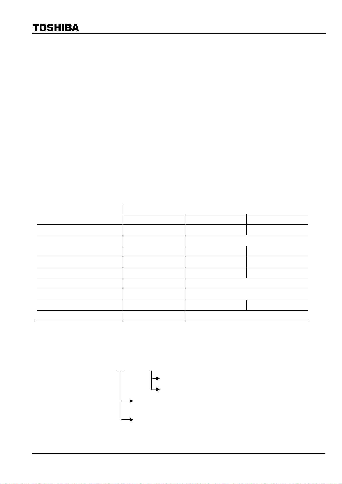
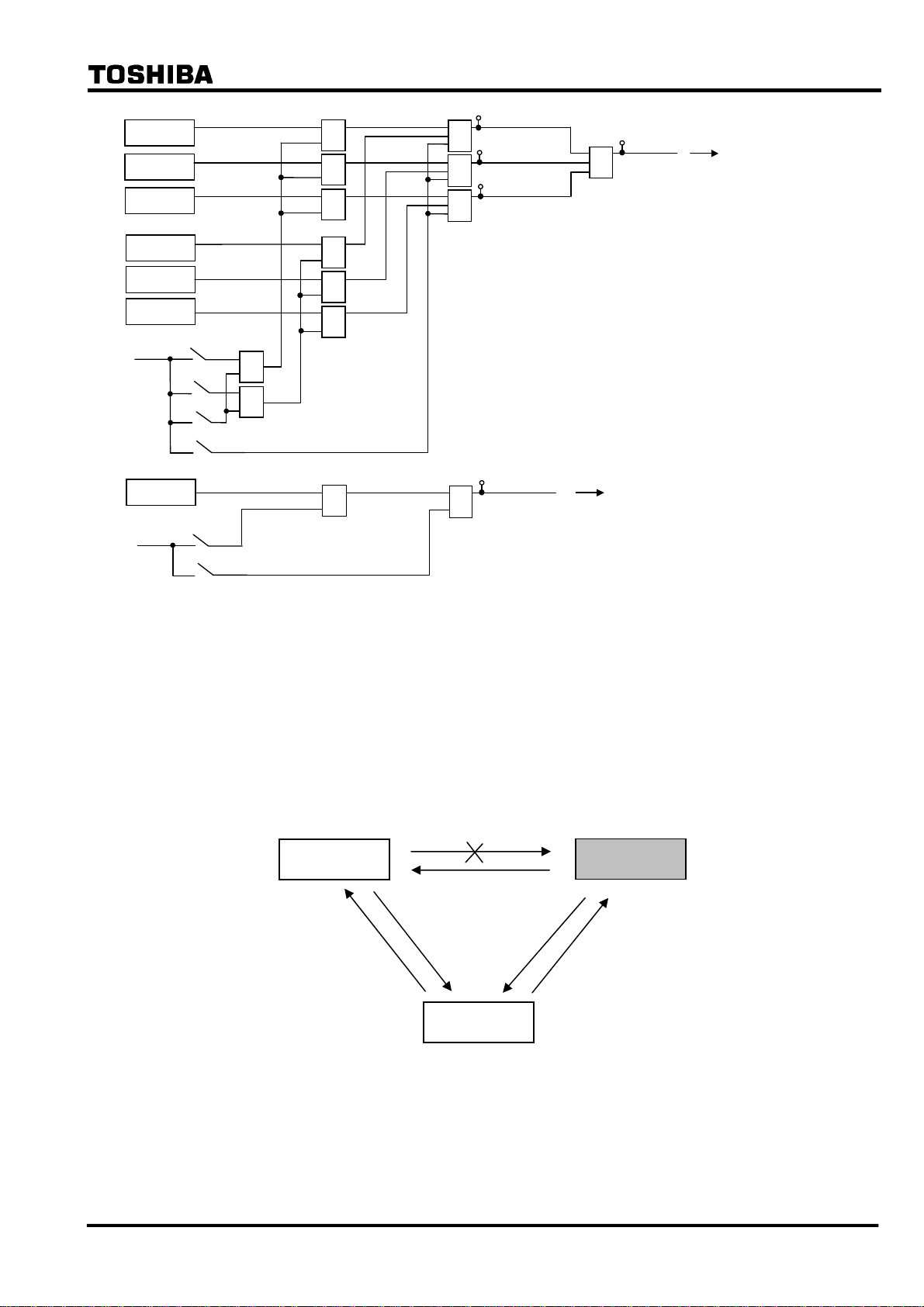
Figure 2.2.2.1 shows the scheme logic of the segregated-phase current differential protection.
Output signals of differential elements DIF-A, -B and -C can perform instantaneous tripping of
the breaker on a per phase basis and start the incorporated autoreclose function.
Note: For the symbols used in the scheme logic, see Appendix L.
DIF-A
DIF-B
DIF-C
Communication
failure
DIF_BLOCK
1585
CRT_BLOCK
1544
TELEPROTEC TION OFF
from IEC103 command)
&
&
&
1
1
41
42
43
&
82: DIF-A_TRIP
&
83: DIF-B_TRIP
&
84: DIF-C_TRIP
&
401
&
402
&
403
&
43C ON
DIF.FS-A_TP
DIF.FS-B_TP
DIF.FS-C_TP
400
≥1
DIF.FS_TRIP
DIF-A_FS
1616
DIF-B_FS
1617
DIF.FS_OP
1618
DIF-C_FS
Figure 2.2.2.1 Scheme Logic of Segregated-phase Current Differential Protection
⎯ 14 ⎯

6 F 2 S 0 8 3 5
Tripping output signals can be blocked by the PLC command DIF_BLOCK and CRT_BLOCK.
The output signals of DIF-A, DIF-B and DIF-C are also blocked when a communication circuit
failure is detected by the data error check, sampling synchronism check or interruption of the
receive signals. For DIF-A_FS, DIF-B_FS and DIF-C_FS signals, see Section 2.2.4.
The differential elements DIF have a percentage restraining characteristic with weak restraint in
the small current region and strong restraint in the large current region, to cope with CT
saturation. (For details of the characteristic, see Section 2.11.)
Erroneous current data may be transmitted from the remote terminal when the remote relay is
out-of-service for testing or other purposes. To prevent false operation in this case, the relay sets
the receiving current data to zero in the differential current calculation upon detecting that the
remote terminal is out-of-service.
If the relay is applied to a three-terminal line, the zero setting is performed only for the current
data received from an out-of-service terminal.
Figure 2.2.2.2 shows the remote terminal out-of-service detection logic. The local terminal
detects that the remote terminal is out-of-service by receiving a signal LOCAL TEST which is
transmitted when the scheme switch [L. TEST] is set to "ON" at the terminal under test. As an
alternative means, the local terminal can detect it by using the circuit breaker and disconnector
status signal CBDS-A, B and C transmitted from the remote out-of-service terminal. The signal
CBDS-A is "1" when both the circuit breaker and disconnector are closed. Thus, out-of-service
is detected when either the circuit breaker or disconnector is open in all three phases.
Zero setting of the receive current data is also performed at the terminal under test. If the scheme
switch [L. TEST] is set to "ON" or the signal R.DATA_ZERO is input by PLC, all the receive
current data transmitted from the in-service terminal is set to zero and this facilitates the local
testing. The zero setting of the receive current data is not performed by the alternative way as
mentioned above.
The out-of-service detection logic can be blocked by the scheme switch [OTD].
Receiving
signal from
Remote
Terminal 1
(∗) Out-of-service detection logic for the remote 2 is same as above.
R.DATA_ZERO
1623
LOCAL_TEST1
CBDS-A
CBDS-B
CBDS-C
[OTD]
(+)
"ON"
≥1
≥1
1
1
(+)
&
[Open1]
"ON"
≥1
≥1
REM1_IN_SRV: Remote 1 i n-servic e
REM1_OFF_SRV: Remote 1 out-of-service
REM1_NON_USE: Rem ote 1 not used
Figure 2.2.2.2 Out-of-Service Detection Logic
Note: When a communication circuit is disconnected or communication circuit failure occurs, do
not close the circuit breaker. When closing it, make sure that the DIF element is blocked.
(Otherwise, it may cause malfunction.)
207
REM1_IN_SRV
208
REM1_OFF_SRV
209
1
REM1_NON_USE
2.2.3 Zero-phase Current Differential Protection
The GRL100 provides sensitive protection for high-impedance earth faults by employing
zero-phase current differential protection. For more sensitive protection, residual current is
introduced through an auxiliary CT in the residual circuit instead of deriving the zero-phase
current from the three phase currents.
⎯ 15 ⎯
6 F 2 S 0 8 3 5
The zero-phase current differential element has a percentage restraining characteristic with weak
restraint. For details of the characteristic, see Section 2.11.
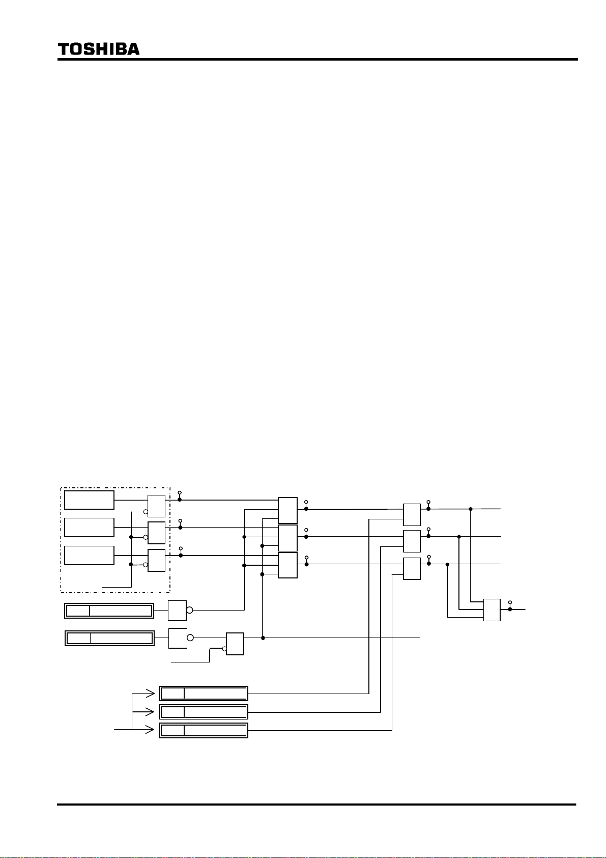
The scheme logic is shown in Figure 2.2.3.1. The output signal of the differential element DIFG
performs time-delayed three-phase tripping of the circuit breaker with the tripping output signal
DIFG.FS_TRIP. DIFG.FS_TRIP can start the incorporated autoreclose function when the
scheme switch [ARC-DIFG] is set to "ON".
Tripping output signal can be blocked by the PLC command DIFG_BLOCK and CRT_BLOCK.
The output signal is also blocked when a communication circuit failure is detected by data error
check, sampling synchronism check or interruption of the receive signals. For DIFG_FS signal,
see Section 2.2.4.
Since the DIFG is used for high-impedance earth fault protection, the DIFG output signal is
blocked when zero-phase current is large as shown in the following equation:
Σ ⎜I
01⎜ ≥ 2 pu or Σ ⎜I02⎜ ≥ 2 pu
where,
Σ ⎜I
Σ ⎜I
01⎜: Scalar summation of zero-phase current at local terminal relay
02⎜: Scalar summation of zero-phase current at remote terminal relay
pu: per unit value
In GPS-mode setting and backup mode (refer to 2.2.7.2), DIFG is blocked.
DIFG
Σ⏐I01⏐≥2PU
Σ⏐I02⏐≥2PU
Communication failure
DIFG_BLOCK
1586
43C ON
DIFG.FS_OP
Figure 2.2.3.1 Scheme Logic of Zero-phase Current Differential Protection
≥1
1619
1
1
DIFG_FS
TDIFG
44
+
t 0
0.00-10.00s
[DIFG]
"ON"
&
85
DIFG_TRIP
86
&
404
&
DIFG.FS_TRIP
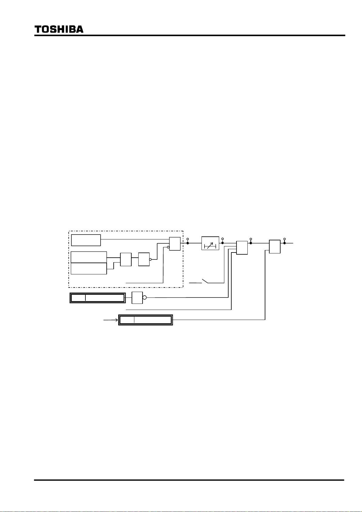
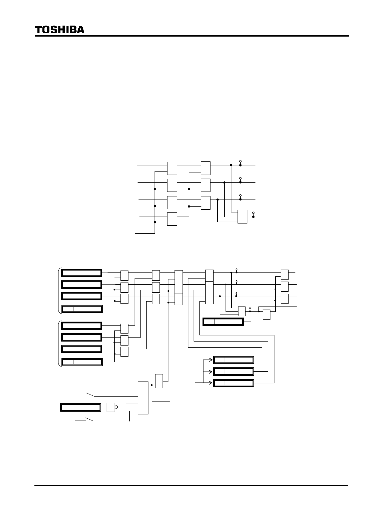
2.2.4 Fail-safe Function
GRL100 provides OC1, OCD and EFD elements. These are used for fail-safe to prevent
unnecessary operation caused by error data in communication failure. OC1 is phase overcurrent
element and its sensitivity can be set. OCD is phase current change detection element, and EFD
is zero-sequence current change detection element. Both of the OCD and EFD sensitivities are
fixed. The scheme logic is shown in Figure 2.2.4.1.
The outputs of DIF.FS_OP and DIFG.FS_OP signals are connected to DIF-A_FS, DIF-B_FS,
DIF-C_FS and DIFG_FS respectively by PLC function. These are connected at the default
setting.
The fail-safe functions are disabled by [DIF-FS] and [DIFG-FS] switches. In the [DIF-FS], OC1
or OCD or both elements can be selected. If these switches are set to “OFF”, the signals of
DIF.FS_OP and DIFG.FS_OP are “1” and the fail-safe is disabled.
⎯ 16 ⎯
6 F 2 S 0 8 3 5
+
+
OC1-A
OC1-B
OC1-C
OCD-A
OCD-B
OCD-C
[DIF-FS]
EFD
[DIFG-FS]
"OC"
OCD"
"
BOTH"
"
OFF"
"
"ON"
409
≥
1
&
&
&
&
&
&
≥1
≥
1
&
DIF.FS-A_OP
410
≥
1
DIF.FS-B_OP
411
≥
1
DIF.FS-C_OP
≥
1
DIFG.FS_OP
412
408
≥
1
DIF.FS_OP
DIFG_FS
(see Fig. 2.2.3.1.)
DIF-A_FS
DIF-B_FS
DIF-C_FS
(see Fig. 2.2.2.1.)
OFF"
"
Figure 2.2.4.1 Fail-safe Logic
2.2.5 Remote Differential Trip
Note: This function is available only when the three-terminal protection is applied by
setting the scheme switch [TERM] to “3-TERM”. In the case of A-MODE setting,
this function is not available.
When one of the telecommunication channels fails, the terminal using the failed channel is
disabled from performing current differential protection, as a result of the failure being detected
through by the telecommunication channel monitoring.
GRL100
GRL100
GRL100
Figure 2.2.5.1 Protection Disabled Terminal with Channel Failure
The remote differential trip (RDIF) function enables the disabled terminal to trip by receiving a
trip command from the sound terminal, which continues to perform current differential
protection.
⎯ 17 ⎯
6 F 2 S 0 8 3 5
Figure 2.2.5.2(a) and (b) show the RDIF scheme logic at RDIF command sending terminal (=
sound terminal) and command receiving terminal (= disabled terminal). The sound terminal
sends the command when the tripping signals RDIF-A-S, RDIF-B-S, RDIF-C-S or RDIF-S are
output locally and the scheme switches [RDIF] and [TERM] are set to “ON” and “3-TERM”
respectively. The RDIF command is sent to the remote terminal via the 64kb/s digital link
together with other data and signals.
The receiving terminal outputs a local three-phase trip signal RDIF-TRIP under the conditions
that when the command RDIF1 or RDIF2 is received from either of the remote terminals, local
differential protection does not operate, the scheme switches [RDIF] and [TERM] are set to
“ON” and “3-TERM” respectively and no communication channel failure exists in the channel
which received the RDIF command.
When the RDIF function is applied, the command sending signals and receiving signals must be
assigned by PLC function.
DIF-A_TRIP
DIF-B_TRIP
DIF-C_TRIP
DIF-G_TRIP
&
&
&
≥1
≥1
≥1
&
451
452
453
≥1
RDIF-A-S
RDIF-B-S
RDIF-C-S
454
RDIF-S
Receiving
signal from
Remote
Terminal 1
Receiving
signal from
Remote
Terminal 2
RDIF-A-R1
1684
RDIF-B-R1
1685
RDIF-C-R1
1686
RDIF-R1
1687
RDIF-A-R2
1716
RDIF-B-R2
1717
RDIF-C-R2
1718
RDIF-R2
1719
DIF elements not operated
43C ON
1598
[TERM]
+
“3-TERM” &
RDIF_BLOCK
[RDIF]
+
“ON”
RDIF_ON
≥1
≥1
≥1
≥1
≥1
≥1
1
(a) Sending terminal
≥1
≥1
≥1
&
&
&
&
1649
DIF.FS_OP
RDIF_ON
(b) Receiving Terminal
&
&
&
RDIF_3PTP
1624
1625
1626
456
457
458
≥1
RDIF-A_FS
RDIF-B_FS
RDIF-C_FS
RD.FS-A_ TRIP
RD.FS-B_ TRIP
RD.FS-C_ TRIP
455
&
≥1
≥1
≥1
RD.FS-A TP
RD.FS-B TP
RD.FS-C TP
RD.FS_TRIP
Figure 2.2.5.2 Remote Differential Trip
⎯ 18 ⎯

6 F 2 S 0 8 3 5
2.2.6 Transmission Data
The following data are transmitted to the remote terminal via the 64kb/s digital link. The data
depends on the communication mode and whether a function is used or not. The details are
shown in Appendix N.
A-phase current
B-phase current
C-phase current
Residual current
Positive sequence voltage
A-phase differential element output signal
B-phase differential element output signal
C-phase differential element output signal
A-phase breaker and disconnector status
B-phase breaker and disconnector status
C-phase breaker and disconnector status
Scheme switch [LOCAL TEST] status
Scheme switch [TFC] status
Reclose block command
Sampling synchronization control signal
Synchronized test trigger signal
User configurable data
Current and voltage data are instantaneous values which are sampled every 30 electrical degrees
(12 times per cycle) and consist of eleven data bits and one sign bit. This data is transmitted
every sample to the remote terminal.
Three differential element outputs and the transfer trip command are related to remote terminal
tripping and are transmitted every sampling interval.
Other data is transmitted once every power cycle.
The data transmission format and user configurable data are also shown in Appendix N.
A synchronized test trigger signal is used to test the differential protection simultaneously at all
terminals. For details, see Section 6.5.3.
In addition to the above data, cyclic redundancy check bits and fixed check bits are transmitted to
monitor the communication channel. If a channel failure is detected at the local terminal, all the
local and remote current and voltage data at that instant are set to zero and outputs of the
differential protection and out-of-step protection are blocked, and these protections of remote
terminal are also blocked because the channel failure is also detected at the remote terminal.
2.2.7 Synchronized Sampling
The GRL100 performs synchronized simultaneous sampling at all terminals of the protected
line. Two methods are applied for the sampling synchronization; intra-system synchronization
and GPS-based synchronization. The former is applied to communication modes A-MODE and
⎯ 19 ⎯
6 F 2 S 0 8 3 5
B-MODE, and the latter is applied to GPS-MODE.
The intra-system synchronization keeps the sampling timing error between the terminals within
±10μs or ±20μs and the GPS-based system keeps it within ±5μs or ±10μs for two- or
three-terminal applications.
In both methods, the sampling synchronization is realized through timing synchronization
control and sampling address synchronization control. These controls are performed once every
two power cycles.
2.2.7.1 Intra-system Synchronized Sampling for A-MODE and B-MODE
The synchronized sampling is realized using sampling synchronization control signals
transmitted to other terminals together with the power system data. This synchronized sampling
requires neither an external reference clock nor synchronization of the internal clocks of the
relays at different terminals. The transmission delay of the channel is corrected automatically.
Timing synchronization
One of the terminals is selected as the time reference terminal and set as the master terminal. The
other terminal is set as the slave terminal. The scheme switch [SP.SYN] is used for the settings.
Note: The master and slave terminals are set only for the convenience of the sampling timing
synchronization. The GRL100s at all terminals perform identical protection functions and
operate simultaneously.
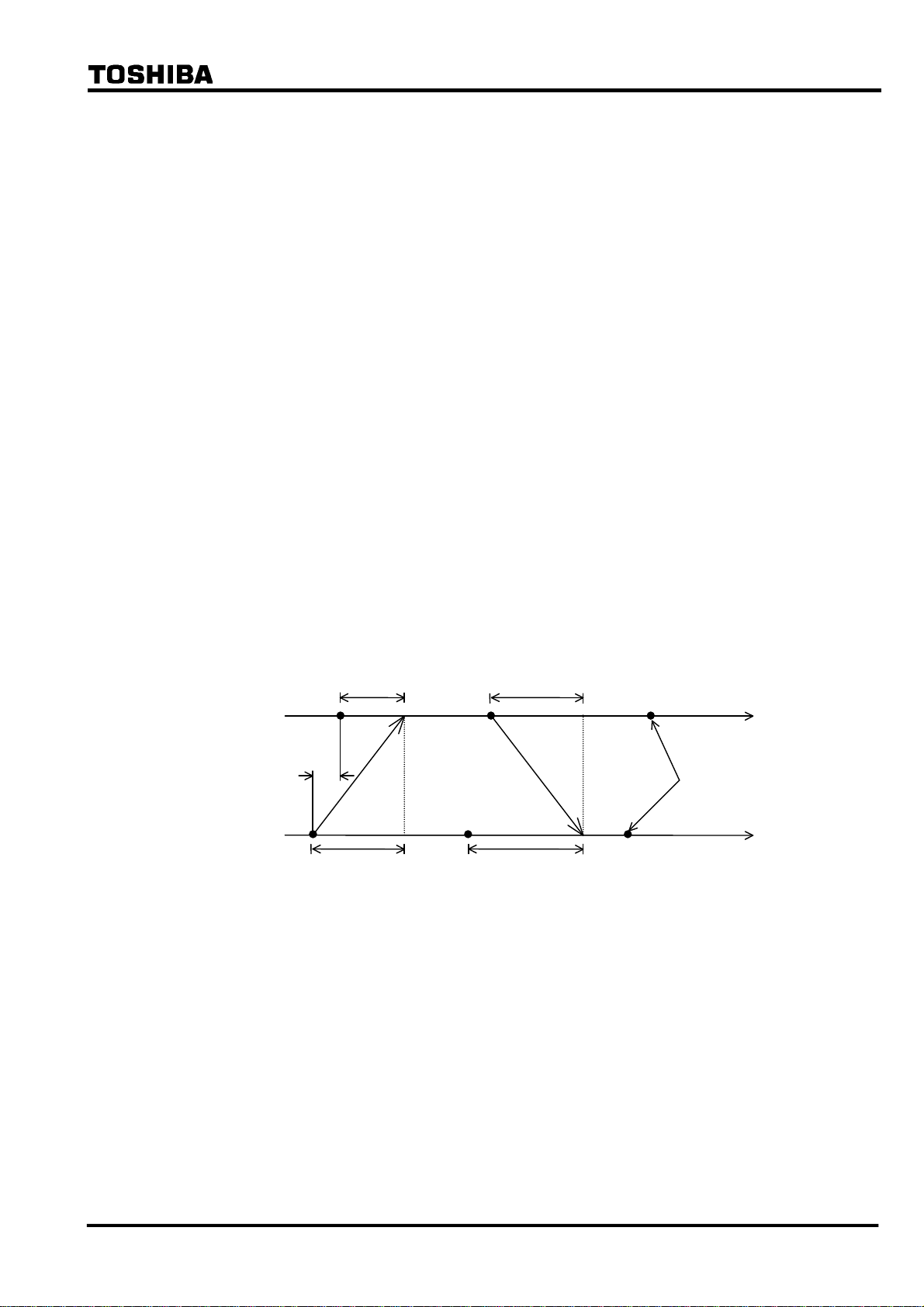
To perform timing synchronization for the slave terminal, the sampling time difference between
master and slave terminals is measured. The measurement principle of the sampling time
difference ΔT is indicated in Figure 2.2.7.1. The master terminal and slave terminal perform
their own sampling and send a signal that becomes the timing reference for the other terminal.
Master
terminal
Slave
terminal
TM
ΔT
Td1
Figure 2.2.7.1 Timing Synchronization
T
d2
t
Sampling
timing
t
T
F
Each terminal measures the time TM and TF from its own sampling instant to the arrival of the
signal from the other terminal. As is evident from the figure, the times TM and TF can be
obtained by equation (1) and (2) where Td1 and Td2 are the transmission delay of the channel in
each direction. The sampling time difference ΔT can be obtained from the resulting equation (3).
TM = Td1 − ΔT (1)
TF = Td2 + ΔT (2)
ΔT = {(TF − TM) + (Td1 − Td2)}/2 (3)
The slave terminal advances or retards its sampling timing based on the time ΔT calculated from
equation (3), thereby reducing the sampling time difference with the master terminal to zero.
This adjustment is performed by varying the interval of the sampling pulse generated by an
⎯ 20 ⎯
6 F 2 S 0 8 3 5
oscillator in the slave terminal.
The difference of the transmission delay time Tdd (= Td1 − Td2) is set to zero when sending and
receiving take the same route and exhibit equal delays. When the route is separate and the
sending and receiving delays are different, Tdd must be set at each terminal to be equal to the
sending delay time minus the receiving delay time. The maximum Tdd that can be set is 10ms.
(For setting, see Section 4.2.6.7. The setting elements of transmission delay time difference are
TCDT1 and TCDT2.)
The time TM measured at the master terminal is sent to the slave terminal together with the
current data and is used to calculate the ΔT.
The permissible maximum transmission delay time of the channel is 10ms.
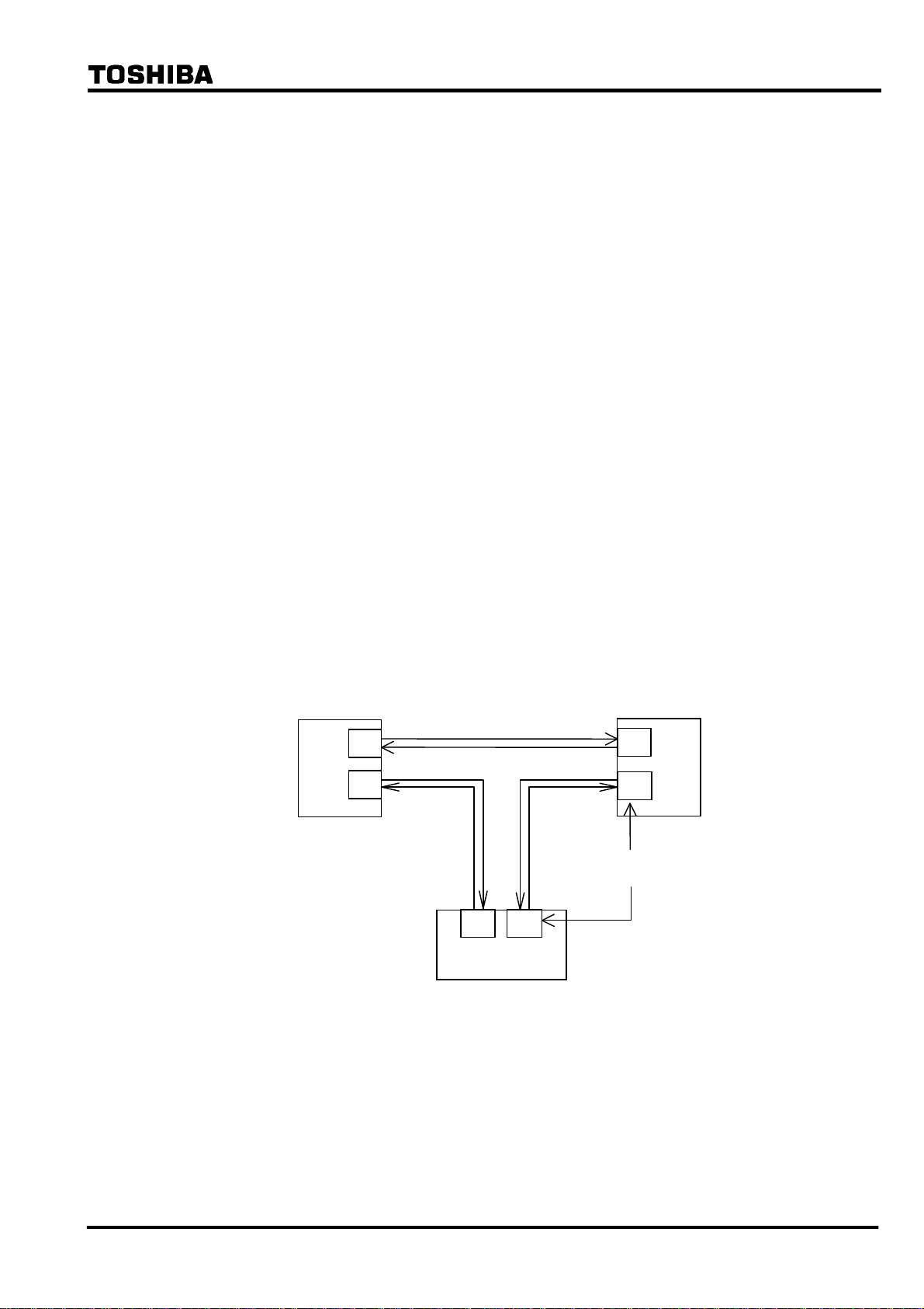
In case of the three-terminal line application, the communication ports of the GRL100 are
interlinked with each other as shown in Figure 2.2.7.2, that is, port CH1 of one terminal and port
CH2 of the other terminal are interlinked. For the setup of the communication system, see
Section 2.12.3.
When terminal A is set as the master terminal by the scheme switch [SP.SYN], the
synchronization control is performed between terminals A and B, and terminals B and C. The
terminal B follows the terminal A and the terminal C follows the terminal B. The slave terminals
perform the follow-up control at their communication port CH2.
When the master terminal is out-of-service in A-MODE, the slave terminal that is interlinked
with port 1 of the master terminal takes the master terminal function. In the case shown in Figure
2.2.7.2, terminal B takes the master terminal function when the master terminal A is
out-of-service. In B-MODE and GPS-MODE, even if the master terminal is out-of-service, the
master terminal is not changed. If DC power supply of the out-of-service terminal is “OFF”,
differential elements at all terminals are blocked. Therefore, the [TERM] setting change from
“3TERM” to “2TERM” is required.
Terminal A
GRL100
CH1
CH2
Master
CH1 CH2
GRL100
Terminal C
Slave
Terminal B
CH2
GRL100
CH1
Slave
Communication
port
Figure 2.2.7.2 Communication Link in Three-terminal Line
Sampling address synchronization
The principle of sampling address synchronization control is indicated in Figure 2.2.7.3. After
time synchronization has been established, the slave terminal measures the time from sending its
own timing reference signal until it returns from the master terminal. The transmission delay
time Td1 from slave to master terminal can be calculated from equation (4).
⎯ 21 ⎯

6 F 2 S 0 8 3 5
Td = ({To − (T − TM)}/2 + Tdd)/2 (4)
The calculated transmission delay time Td1 is divided by the sampling interval T. The mantissa
is truncated and the quotient is expressed as an integer. If the integer is set to P, the reception at
the slave terminal of the signal sent from the master terminal occurs at P sampling intervals from
the transmission. Accordingly, by performing control so that the sampling address of the slave
terminal equals integer P when the sampling address = 0 signal is received from the master
terminal, the sampling address of the slave terminal can be made the same as the master term inal.
T
t
Master
terminal
T
M
Slave
terminal
T
F
T
d1
T
O
T
d2
t
Figure 2.2.7.3 Sampling Address Synchronization
2.2.7.2 GPS-based Synchronized Sampling for GPS-MODE
The relays at all terminals simultaneously receive the GPS clock signal once every second.
Figure 2.2.7.4 shows the GPS-based synchronized sampling circuit at one terminal. The GPS
clock signal is received by the GPS receiver HHGP1 and input to a time difference measurement
circuit in the GRL100. The circuit measures the time difference ΔT between the GPS clock and
the internal clock generated from the crystal oscillator. The oscillator is controlled to
synchronize with the GPS clock using the measured ΔT and outputs 2,400 Hz (50Hz rating)
sampling signals to the current sampling circuit (analog to digital converter).
GPS
Line
GRL100
GPS receiver
HHGP1
Time
difference
measurement
ΔT
Crystal
oscillator
Lead/lag control
Analog/digital
converter
Synchronous control
Figure 2.2.7.4 GPS Clock-based Sampling
Timing synchronization
When the GPS signal is received normally at every line terminal, the GRL100 performs
synchronized sampling based on the received clock signal. The GRL100 can provide a backup
synchronization system if the GPS signal is interrupted at one or more terminals, and perform
synchronized sampling without any external reference clock. The backup system becomes valid
by setting the scheme switch [GPSBAK] to "ON".
⎯ 22 ⎯

6 F 2 S 0 8 3 5
In the backup modes, the percentage restraint in the small current region can be increased from
the normal 16.7% ((1/6)Ir in Figure 2.9.10.1) in accordance with the PDTD setting which is the
probable transmission delay time difference between send and receive channels.
Backup modes, Mode 1, 2A and 2B are initialised when the backup system is set valid.
If the GPS signal interruption occurs when the backup is set invalid, the sampling runs based on
the local clock. When the arrival time of the remote signal measured from local sampling instant
deviates from a nominal time, the protection is blocked.
Mode 0: When the GPS signal is received normally, the sampling is performed synchronizing
with the received clock signal thus realizing synchronized sampling at all terminals. Difference
of the transmission delay time for the channel in each direction and fluctuation of the delay time
can be permitted.
The GRL100 performs the protection based on the nominal current differential characteristics.
When the GPS signal has interrupted for more than ten seconds at any of the terminals, the mode
changes to Mode 1 at all terminals.
Mode 1: The terminal which loses its GPS signal first functions as the slave terminal. If all
terminals lose their signals simultaneously, then the scheme switch [SP.SYN] setting determines
which terminal functions as the slave or master. The slave terminal adjusts the local sampling
timing to synchronize the sampling with other terminal which is receiving the GPS signal
regularly or with the master terminal.
Note: When two terminals are receiving the GPS signal regularly, the slave terminal
synchronizes with the terminal that is interlinked with port 2 of the slave terminal.
When the GPS signal has been restored, the mode shifts from Mode 1 back to Mode 0.
If, during Mode 1 operation, a failure occurs in the communication system, the sampling timing
adjustment is disabled and each terminal runs free. If the free running continues over the time
determined by the PDTD setting or the apparent phase difference exceeds the value determined
by the PDTD setting, the mode shifts from Mode 1 to Mode 2A at all terminals.
Mode 2A: In this mode, the intra-system synchronization described in 2.2.7.1 is applied
assuming that the transmission delay time for the channel in each direction is identical.
Fluctuation of the delay time can be permitted.
The current differential protection is blocked in this mode.
When the GPS signal has been restored, the mode shifts from Mode 2A to Mode 0.
If the GPS signal interruption occurs a set period following energisation of the relay power
supply or the mode returned to Mode 0 from Mode 1, 2A or 2B, then the transmission delay time
measurement will not be completed in Mode 0, and the mode changes to Mode 2A.
When the apparent current phase difference has stayed within the value determined by the PDTD
setting, the scheme switch [AUTO2B] for automatic mode change is set to "ON" and [TERM] is
set to "2TERM", the mode changes from Mode 2A to Mode 2B at both terminals.
The mode can be changed to Mode 2B manually through a binary input signal "Mode 2B
initiation" or user interface. Before this operation, it must be checked that the transmission delay
time difference between send and receive terminals is less than the PDTD setting and the SYNC
ALARM LED is off. If these conditions are not satisfied, the operation may cause a false
tripping.
Note: The mode change with the binary input signal is performed by either way:
• If the binary input contact is such as to be open when the relay is in service, set
the BI to "Inv" (inverted). The mode changes when the contact is closed more
⎯ 23 ⎯
θ
6 F 2 S 0 8 3 5
than 2 seconds and then open.
• If the binary input contact is such as to be closed when the relay is in service, set
the BI to "Norm" (normal). The mode changes when the contact is open more
than 2 seconds and then closed.
For the BISW4, see Section 3.2.1.
In the three-terminal application, the mode change to Mode 2B is available even
when one of the three communication routes is failed.
Mode 2B: The same intra-system synchronization as in Mode 2A is applied.
When the GPS signal has been restored, the mode shifts from Mode 2B to Mode 0.
If a failure occurs in the communication system, the sampling timing adjustment is disabled and
each terminal runs free.
The mode shifts from Mode 2B to Mode 2A, when the apparent load current phase difference
exceeds the value determined by the PDTD setting for pre-determined time.
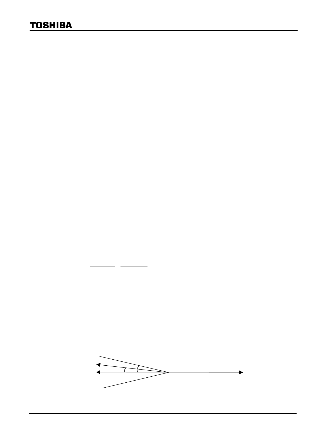
Checking the current phase difference (For two-terminal application setting only)
The current phase difference is checked using the following equations:
I
1A ⋅ cos θ < 0
1A ⋅ I1B sin θ < I1A ⋅ I1B sin θs
I
I
1A > OCCHK
I
1B > OCCHK
Where,
I
1A = Positive sequence component of load current at local terminal
1B = Positive sequence component of load current at remote terminal
I
θ = Phase difference of I
1B from - I1A
θs = Critical phase difference
= CHKθ‐HYSθ
CHKθ =
PDTD(μs)
2
360°
×
20000(μs)
+ 8.5°
HYSθ = Margin of phase difference checking
OCCHK = Minimum current for phase difference check
If the magnitude of I
1A and I1B exceed the setting and the conditions for both equations above are
established, then the sampling is regarded to be synchronized.
If the current phase difference exceeds a set value, the "SYNC ALARM" LED on the front panel
is lit.
Checking the current phase difference is enabled by setting the scheme switches [TERM] to
"2TERM" and [SRCθ] to "I".
I1B
-I1A
s
θ
I1A
Figure 2.2.7.5 Current Phase Difference Check
⎯ 24 ⎯
6 F 2 S 0 8 3 5
Sampling address synchronization
The same method as described in section 2.2.7.1 is employed in Mode 0 and Mode 2A where the
sampling synchronization must be established. It is not employed in Mode 1 and 2B because the
sampling address synchronization has already been established in the previous mode.
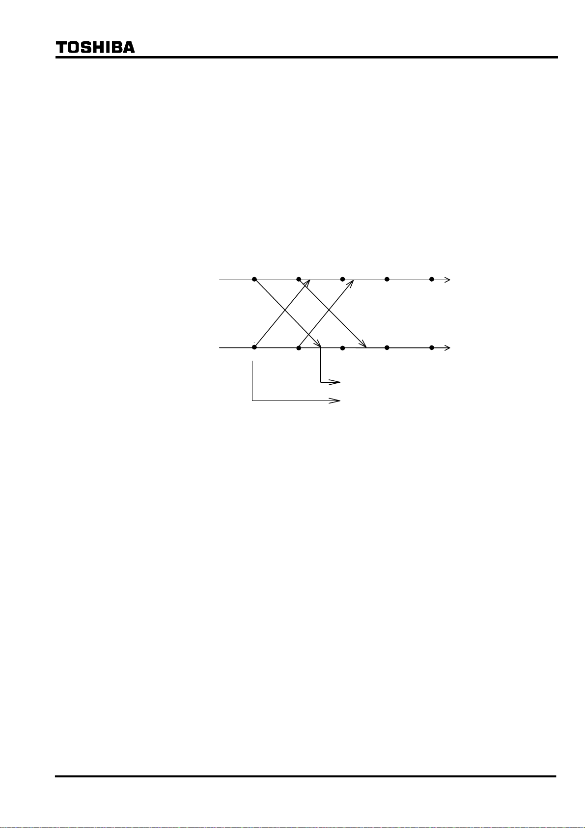
2.2.7.3 Differential Current Calculation
Synchronized sampling allows correct calculation of differential current even in the presence of
a transmission time delay. This processing is indicated in Figure 2.2.7.6. As indicated in the
figure, sampling synchronization is established between terminals A and B, and both the
sampling timing and sampling address match. The instantaneous current data and sampling
address are both sent to the other terminal. The GRL100 refers to the sampling address affixed to
the received data and uses local data with the same sampling address to calculate the differential
current. This allows both terminals to use data sampled at the same instant to perform the
differential current calculation, no matter how large the transmission time delay is.
Terminal A
4 3210
t
i
A(0)
i
B(0)
Terminal B
Figure 2.2.7.6 Calculation of Differential Current with Transmission Delay Time
i
B(1)
i
A(1)
i
A(0)
Differential current calculation
i
B(0)
Sampling address number
t
4 3210
Protection in anomalous power system operation
Even when any of the terminals is out-of-service, the GRL100 in-service terminal can still
provide the differential protection using the out-of-service detection logic. For details of the
out-of-service detection logic, see Section 2.2.2.
When one terminal is out-of-service in a two-terminal line, the other terminal continues the
current differential protection using the local current irrespective of whether it is a master
terminal or a slave terminal.
When one terminal is out-of-service in a three-terminal line, synchronized sampling is
established between the remaining two terminals as follows and the differential protection is
maintained.
• If the master terminal is out-of-service, one of the slave terminals takes over the master
terminal synchronized sampling function and enables current differential protection
between the remaining terminals to be performed.
• If the slave terminal is out-of-service, the master and another slave terminal maintain the
differential protection.
When two terminals are out-of-service in a three-terminal line, the remaining terminal continues
the current differential protection using the local current irrespective of whether it is a master
terminal or a slave terminal.
2.2.8 Charging Current Compensation
When differential protection is applied to underground cables or long overhead transmission
⎯ 25 ⎯
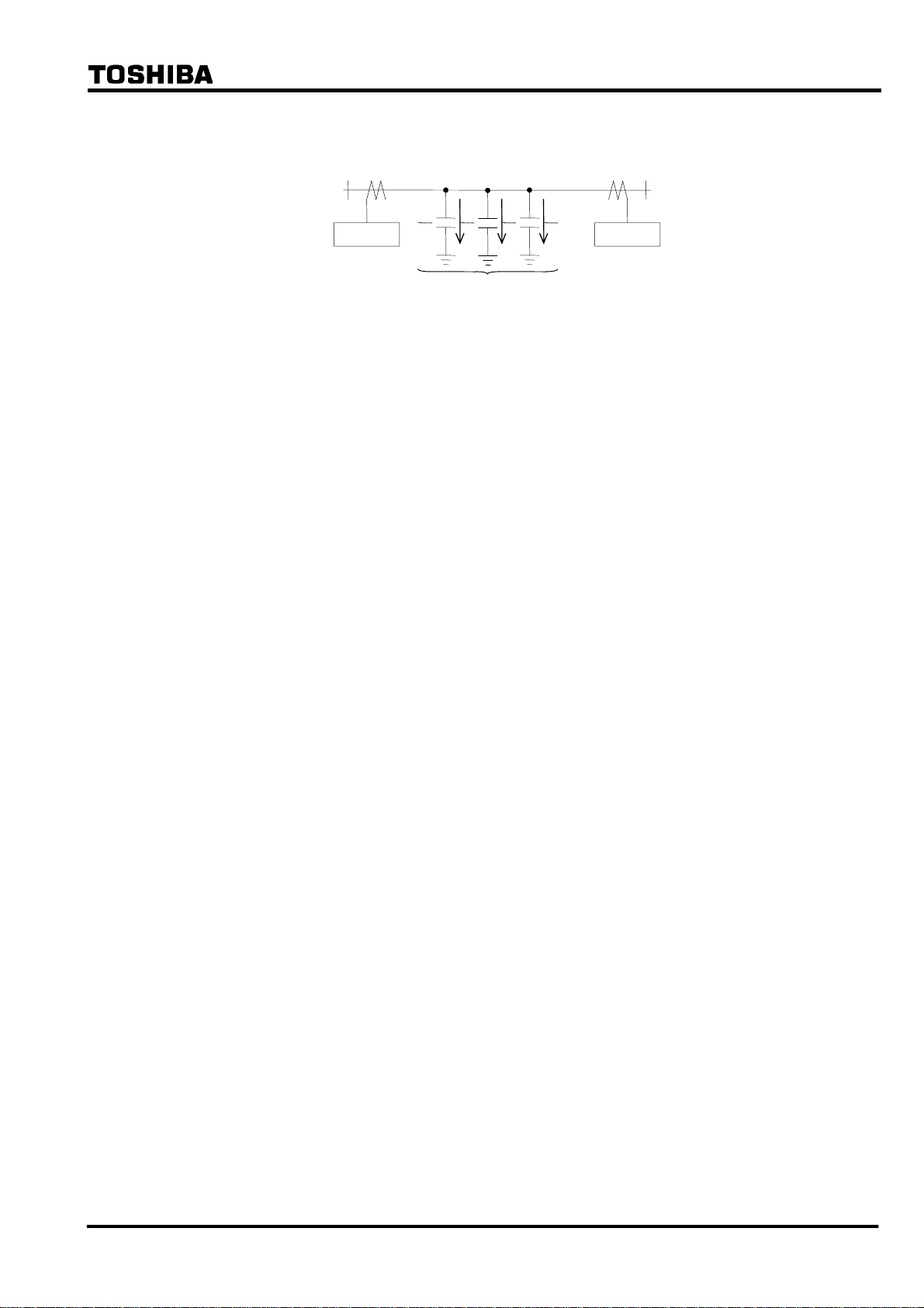
6 F 2 S 0 8 3 5
lines, the charging current which flows as a result of the capacitance of the line (see Figure
2.2.8.1) appears to the protection relay as an erroneous differential current.
Terminal A Terminal B
GRL100 GRL100
Ic
Figure 2.2.8.1 Charging Current
The charging current can be compensated for in the setting of the relay’s differential protection
sensitivity but only at the expense of reduced sensitivity to internal faults. In addition, the actual
charging current varies with the running voltage of the line and this must be taken into account in
the setting.
In order to suppress the effect of the charging current while maintaining the sensitivity of the
differential protection, GRL100 is equipped with a charging current compensation function,
which continuously re-calculates the charging current according to the running line voltage and
compensates for it in its differential current calculation. The running line voltage is measured by
VT inputs to GRL100.
The user enters values for line charging current and for the line voltage at which that charging
current was determined in the settings [DIFIC] and [Vn], and these values are used by the relay
to calculate the capacitance of the line. The relays at each line end share the line capacitance
between them, that is they divide by two for a two-terminal line, and by three for a three-terminal
line. In the case of a three-terminal line, if the relay at one terminal is out-of-service for testing
(see out-of-service terminal detection), the other two terminals are automatically re-configured
to divide the line capacitance by two.
Each terminal continuously calculates its share of the charging current at the running line voltage
on a sample by sample basis as follows:
Ic = C
dV
/ dt
where,
Ic = line charging current
C = line capacitance calculated from settings [DIFIC] and [Vn]
V = measured line voltage
The relay then calculates the line current compensated for the charging current on a sample by
sample basis as follows:
I = I’ - Ic
where,
I = compensated current
I’ = actual measured current
Note that since GRL100 calculates both the charging current and compensated line current on a
sample by sample basis, all necessary phase information is inherently taken into account.
⎯ 26 ⎯

6 F 2 S 0 8 3 5
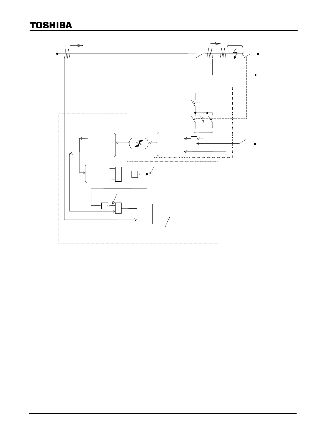
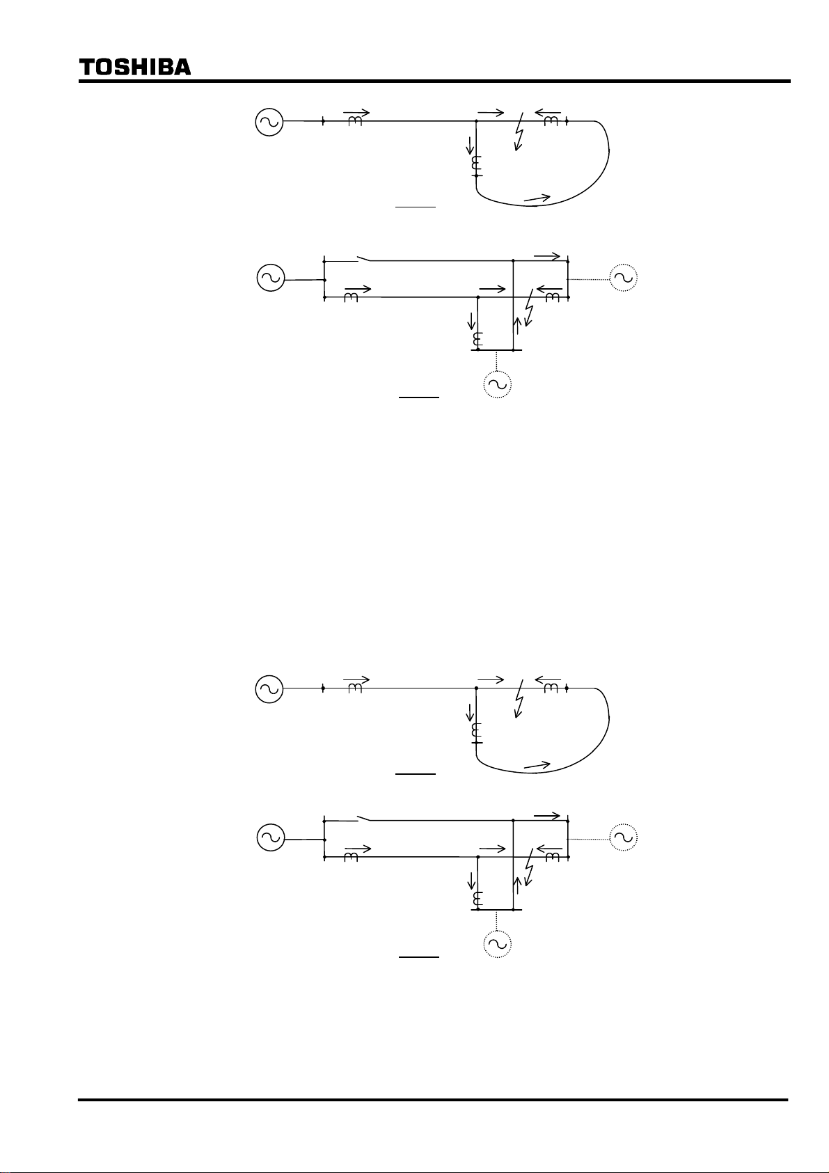
2.2.9 Blind Zone Protection
The GRL100 relay has “Out-of-Service Detection Logic” as described in Section 2.2.2. This
logic functions automatically to detect the remote CB or DS (line disconnecting switch) opened
condition as shown in Figure 2.2.9.1. If the remote CB or DS is opened, the received remote
current data is set to “zero” Ampere at the local terminal, and the local relay can be operated with
only local current like a simple over current relay. Therefore, this logic function is used for blind
zone protection.
The zone between CB and CT at the remote terminal is the blind zone in Figure 2.2.9.1. If a fault
occurs within this zone, the busbar protection should operate first and trip the CB at the remote
terminal, but the fault remains and the fault current (IF) is fed continuously from the local
terminal. Since this phenomenon is an external fault for the current differential protection
scheme, the blind zone fault cannot be cleared. The fault may be cleared by remote backup
protection following a time delay, but there is a danger of damage being caused to power system
plant. Fast tripping for this type of fault is highly desirable. The Out-of-Service Detection Logic
is effective for a fault where a blind zone between CT and CB on the line exists as shown in
Figure 2.2.9.1.
If the CB and DS condition are introduced at the remote terminal as shown in Figure 2.2.9.1, the
GRL100 relay at the local terminal can operate with only local current and the fault can be
cleared, because the remote current data is automatically cancelled as explained above.
Please note the “CB Close Command” signal must be connected to the GRL100 relay to prevent
unwanted operation for a CB close operation (manual close and/or autoreclose). Unwanted
operation may be caused if the close timing of the CB auxiliary contact is delayed relative to the
CB main contact. Therefore, the CB close command signal resets forcibly the Out-of-Service
Detection Logic before the CB main contact is closed.
CB and DS status signals are input by PLC. If the out-of-service detection is not used, its logic
can be blocked by the scheme switch [OTD].
⎯ 27 ⎯
6 F 2 S 0 8 3 5
LOCAL
IL (=IF)
DIFF RELAY GRL100
(LOCAL)
CBDS-A,B,C
IR(Current)
CBDS-A
CBDS-B
CBDS-C
≧1
LINE
DIFF RELAY GRL100
(REMOTE)
52A 52C 52B
Comm. Link
1
(Cancel circuit of rem ot e t e rminal current IR)
CBDS-A,B,C
IR(Current)
(Remote terminal closed: “0” logic)
Remote terminal “OPEN”
≧
IR (=IF)
DS
89L1
1
Blind Zone
CB
FAULT
CB CLOSE COMMAND
REMOTE
BUSBAR
PROT.
1
&
IR
IL
If DS or CB signals (CBDS -A, B, C) changes to “ 0” , r emo te cu rrent d ata
(IR) is cancelled to zer o (0). Therefor e, differential curr ent (Id ) eq uals to
local current (IL).
Σ
Differential Current (Id)
Figure 2.2.9.1 Blind Zone Protection
2.2.10 Application to Three-terminal Lines
When current differential protection is applied to a three-terminal line, special attention must be
paid to the fault current flowing out of the line in the case of an internal fault and CT saturation at
the outflowing terminal in case of an external fault.
Fault current outflow in case of internal fault
In case of a two-terminal line, fault current never flows out from the terminals for an internal
fault. But in case of a three-terminal line with an outer loop circuit, a partial fault current can
flow out of one terminal and flow into another terminal depending on the fault location and
magnitude of the power source behind each terminal.
Case 1 in Figure 2.2.10.1 shows a fault current outflow in a single circuit three-terminal line with
outer loop circuit. J and F in the figure indicate the junction point and fault point. A part of the
fault current flowing in from terminal A flows out once from terminal C and flows in again from
terminal B through the outer loop.
Case 2 shows the outflow in a double-circuit three-terminal line. The outer loop is generated
when one terminal is open in the parallel line. A part of the fault current flowing in from terminal
A flows out from the fault line to the parallel line at terminal C and flows in again at terminal B
through the parallel line.
⎯ 28 ⎯
A
A
A
A
6 F 2 S 0 8 3 5
J
C
Case 1
B F
Open
Case 2
C
J
F
B
Figure 2.2.10.1 Fault Current Outflow in Internal Fault
The larger current outflows from terminal C when the fault location is closer to terminal B and
the power source behind terminal C is weaker. In case of a double-circuit three-terminal line,
50% of the fault current flowing in from terminal A can flow out from terminal C if terminal C is
very close to the junction and has no power source behind it.
These outflows must be considered when setting the differential element.
CT saturation for an external fault condition
In case of a two-terminal line, the magnitude of infeeding and outflowing currents to the external
fault is almost the same. If the CTs have the same characteristics at the two terminals, the CT
errors are offset in the differential current calculation.
B
J
C
Case 1
Open
J
C
Case 2
F
B
F
Figure 2.2.10.2 Fault Current Distribution
But in case of a three-terminal line, the magnitude of the current varies between the terminals
and the terminal closest to the external fault has the largest magnitude of outflowing fault
current. Thus, the CT errors are not offset in the differential current calculation. Thus, it is
⎯ 29 ⎯

×
×
6 F 2 S 0 8 3 5
necessary to check whether any fault causes CT saturation, particularly in the terminal with
outflow, and the saturation must be accommodated utilising the DIFI2 setting of the DIF
element.
2.2.11 Dual Communication Mode
Three-terminal application models have dual communication mode (GRL100-∗1∗). By
connecting the remote terminal with dual communication routes, even if one of the routes fails, it
is possible to continue sampling synchronization and protection by the current differential relay.
To set dual communication mode, select "Dual" in the TERM setting. Other settings are the same
as that of the two-terminal. In GPS-MODE setting, however, the dual communication mode
cannot be applied.
CH1
GRL100
CH2
CH1
GRL100
CH2
Figure 2.2.11.1 Dual Communication Mode
2.2.12 Application to One-and-a-half Breaker Busbar System
The GRL100 models 301, 311, 302, 501, 511, 503, 513, and 513 are used for lines connected via
a one-and-a-half breaker busbar system, and have functions to protect against stub faults and
through fault currents.
Stub fault
If a fault occurs at F1 or F2 when line disconnector DS of terminal A is open as shown in Figure
2.2.12.1, the differential protection operates and trips the breakers at both terminals.
Terminal A
× ×
F2F1
Terminal B
× ×
DS
Figure 2.2.12.1 Stub Fault
A scheme switch [STUB] and stub fault detection logic as shown in Figure 2.2.12.2 are provided
to avoid unnecessary trippings of the breakers in these cases.
DS
[STUB]
(+)
"ON"
Figure 2.2.12.2 Measure for Stub Fault
1
&
STUB ON
If the switch is set to "ON" and the disconnector is open (DS = 0), the signal STUB ON is
⎯
30 ⎯

6 F 2 S 0 8 3 5
generated and used to reset the receiving current data from terminal B to zero. Thus, terminal A
does not need to operate unnecessarily in response to fault F2.
Terminal B detects that terminal A is out-of-service with the out-of-service detection logic and
resets the receiving current data from terminal A to zero, and so does not operate in response to
fault F1.
The signal STUB ON also brings the local tripping into three-phase final tripping.
Through current for a close-up external fault
In the close-up external fault shown in Figure 2.2.12.3, a large fault current may flow through
current transformers CT1 and CT2 at terminal A and a small fault current flows in at term inal B.
This large through fault current may cause an erroneous differential current if the characteristics
of CT1 and CT2 are not identical.
Terminal A
GRL100 GRL100
CT1CT2
Terminal B
Figure 2.2.12.3 Through Fault Current
The models 503 and 513 have individual input terminals for CT1 and CT2 secondary current.
Thus, sufficient restraining current can be obtained by summing the scalar values of CT1 and
CT2 secondary currents.
In this manner, terminal A can have sufficient restraining current against the erroneous
differential current mentioned above and demonstrate correct non-operation. But terminal B
cannot have a sufficient restraining current and may operate in response to the fault incorrectly.
To cope with this, the GRL100 has a scheme switch [T.F.C] and the scheme logic of the
differential protection shown in Figure 2.2.2.1 is switched to that of Figure 2.2.12.4. When the
[T.F.C] is set to "ON" locally or at the remote terminal, tripping commands are output under the
condition that the differential protection operates at both ends.
In this case, the tripping time is delayed by the transmission time of the remote terminal
operation signal.
⎯
31 ⎯

6 F 2 S 0 8 3 5
DIF-A
DIF-B
DIF-C
Remote Terminal
DIF-A
DIF-B
DIF-C
[T.F.C]
+
"ON"
[T.F.C]
+
"ON"
DIF.BLOCK
≥ 1
&
&
&
DIFAT
DIFBT
DIFCT
&
≥ 1
&
≥ 1
&
1
≥ 1
Figure 2.2.12.4 Scheme Logic for Through Fault Current
Fault current outflow in case of internal fault
As shown in Figure 2.2.12.5, the fault current may outflow in case of an internal fault of
double-circuit lines. The outflow at terminal A increases as the fault location F approaches
terminal B. When the fault is close to terminal B, 50% of the fault current flows out to the
parallel line, though it depends on the power source conditions at terminals A and B.
This outflow must be considered when setting the differential element.
F
Figure 2.2.12.5 Fault Current Outflow in Internal Fault
Terminal B Terminal A
2.2.13 Setting
The following shows the setting elements necessary for the current differential protection and
their setting ranges. The settings can be made on the LCD screen or PC screen.
⎯
32 ⎯

Element Range Step Default Remarks Communication Mode
A B GPS
DIF Phase current
DIFI1
DIFI2
DIFG DIFGI
DIFIC
Vn 100 - 120V 1V 110V Rated line voltage x x x
TDIFG
DIFSV
TIDSV 0 – 60s 1s 10s Timer for Id detection x x x
OCCHK (*5)
HYSθ (*5)
TDSV 100 - 16000
TCDT1
TCDT2
PDTD
RYID 0-63 0 Local relay address
RYID1 0-63 0 Remote 1 relay address
RYID2 0-63 0 Remote 2 relay address
[DIFG] ON/OFF ON High impedance earth fault protection x x x
[STUB] ON/OFF ON or
[RDIF] ON/OFF ON Remote differential protection -- x x
[T.F.C] ON/OFF OFF Measure for through fault current x -- -[OTD] ON/OFF OFF Open terminal detection x x x
[DIF-FS] OFF / OC / OCD /
[DIFG-FS] ON/OFF OFF Fail-safe function x x x
[COMMODE] A / B / GPS B Communication mode A B GPS
[TERM] 2TERM/3TERM
[SP.SYN] Master/Slave Master(*4)
[CH. CON] Normal/Exchange Normal Telecommunication port exchanger x x x
0.50 − 10.00A
(0.10 − 2.00A
3.0 − 120.0A
(0.6 − 24.0A
0.25 − 5.00A
(0.05 − 1.00A
0.00 − 5.00A
(0.00 − 1.00A
0.00 − 10.00s
0.25 − 10.00A
(0.05 − 2.00A
0.5 − 5.0A
(0.10 − 1.00A
1 − 5 deg
−10000 − 10000 1μs 0μs
−10000 − 10000 1μs 0μs
200 - 2000
Both
/Dual (*3)
μs 1μs 1000μs
0.01A 5.00A Small current region x x x
0.01A 1.00A)(*1)
0.1A 15.0A Large current region x x x
0.1A 3.0A)
0.01A 2.50A Residual current x x x
0.01A 0.50A)
0.01A 0.00 A x x x
0.01A 0.00 A)
0.01s 0.50s Delayed tripping timer x x x
0.01A 0.50A x x x
0.01A 0.10A)
0.1A 0.5A -- -- x
0.01A 0.10A)
1 deg 1 deg Phase difference check margin -- -- x
μs 6000μs
1
OFF(*2)
OFF Fail-safe function x x x
3TERM For three-terminal application models x x x
Charging current compensation
Differential current (Id) monitoring
Minimum current for phase difference
check
Transmission delay time threshold
setting for alarm (*8)
Transmission delay time difference
setting for channel 1 (*7)
Transmission delay time difference
setting for channel 2 (*7)
Transmission delay time difference
between send and receive channels
(GPS synchronization only)
Measure for stub fault x x x
Sampling synchronization x x x
6 F 2 S 0 8 3 5
x x x
x x x
x x x
-- -- x
-- x x
-- x x
-- x x
⎯
33 ⎯

6 F 2 S 0 8 3 5
Element Range Step Default Remarks Communication Mode
A B GPS
[T.SFT1] ON/OFF OFF Channel 1 bit shifting for multiplexer x x x
[T.SFT2] ON/OFF OFF Channel 2 bit shifting for multiplexer x x x
[B.SYN1] ON/OFF ON Channel 1 bit synchronising for
x x x
multiplexer
[B.SYN2] ON/OFF ON Channel 2 bit synchronising for
x x x
multiplexer
[LSSV] ON/OFF OFF Disconnector contacts discrepancy
x x x
check
[GPSBAK] OFF/ON ON Backup synchronization -- -- x
[AUTO2B] (*6) OFF/ON OFF Automatic mode change -- -- x
[SRCθ](*5)
Disable / I I Sampling timing deviation monitoring
-- -- x
with current
[IDSV] OFF/ALM&BLK/A
OFF Id monitoring x x x
LM
[RYIDSV] OFF/ON ON Relay address monitoring -- x x
(*1) Current values shown in parentheses are in the case of 1A rating. Other current values are in the
case of 5A rating.
(*2) This setting depends on the relay model.
(*3) This setting is valid for three-terminal application models of the GRL100.
(*4) In the actual setting, one terminal is set to "Master" and other terminal(s) to "Slave".
(*5) OCCHK, [SRCθ] and HYSθ are enabled by setting the [TERM] to "2TERM".
(*6) [AUTO2B] is enabled by setting the [TERM] to "2TERM" and [SRCθ] to "I".
(*7) This setting is only used when there is a fixed difference between the sending and receiving
transmission delay time. When the delay times are equal, the default setting of 0μs must be
used.
(*8) If the channel delay time of CH1 or CH2 exceeds the TDSV setting, then the alarm "Td1 over"
or "Td2 over" is given respectively.
CT Ratio matching
When the CT ratio is different between the local terminal and the remote terminal(s), the CT
ratio matching can be done as follows:
The differential element settings are respectively set to the setting values so that the primary fault
detecting current is the same value at all terminals. Figure 2.2.13.1 shows an example of CT ratio
matching. The settings for DIFI2, DIFGI, DIFSV and DIFIC should also be set with relation to
the primary current in the same manner of the DIFI1 setting.
Primary sensitivity = 800A
Terminal-A
Terminal-B
GRL100
CT ratio : 2000/1A
DIFI1=800A / CT ratio(2000/1A)
= 0.4A
DIFI1=800A / CT ratio(4000/1A)
GRL100
CT ratio : 4000/1A
= 0.2A
Figure 2.2.13.1 Example of CT Ratio Matching
⎯
34 ⎯

6 F 2 S 0 8 3 5
If the CT secondary ratings at the local and remote terminals are different, relay model suitable
for the CT secondary rating is used at each terminal and then CT ratio matching can be applied
the same as above. The differential element settings are respectively set to the setting values so
that the primary fault detecting current is the same value at all terminals. Figure 2.2.13.2 shows
an example of CT ratio matching. The settings for DIFI2, DIFGI, DIFSV and DIFC should also
be set with relation to the primary current in the same manner of the DIFI1 setting.
Terminal-A
Primary sensitivity = 800A
Terminal-B
GRL100
1A rated model
CT ratio : 2000/1A
DIFI1=800A / CT ratio(2000/1A)
= 0.4A
Figure 2.2.13.2 Example of CT Ratio Matching incase of Different CT secondary Rating
GRL100
5A rated model
CT ratio : 2000/5A
DIFI1=800A / CT ratio(2000/5A)
= 2.0A
Setting of DIFI1
The setting of DIFI1 is determined from the minimum internal fault current to operate and the
maximum erroneous differential current (mainly the internal charging current) during normal
service condition not to operate.
DIFI1 should therefore be set to satisfy the following equation:
K⋅Ic < DIFI1 < If / K
where,
K: Setting margin (K = 1.2 to 1.5)
Ic: Internal charging current
If: Minimum internal fault current
For the GRL100 provided with the charging current compensation, the condition related to the
charging current can be neglected.
The setting value of DIFI1 must be identical at all terminals. If the terminals have different CT
ratios, then the settings for DIFI1 must be selected such that the primary settings are identical.
Setting of DIFI2
The setting of DIFI2 is determined from the following two factors:
• Maximum erroneous current generated by CT saturation in case of an external fault
• Maximum load c urrent
• Maximum outflow current in case of an internal fault
In the first factor, the DIFI2 should be set as small as possible so that unwanted operation is not
caused by the maximum erroneous current generated by CT saturation on the primary side by a
through current at an external fault. It is recommended normally to set DIFI2 to 2×In (In:
secondary rated current) for this factor.
In the second factor, the DIFI2 should be set large enough such that it does not encroach on load
current.
The third factor must be considered only when the GRL100 is applied to three-terminal
⎯
35 ⎯

6 F 2 S 0 8 3 5
double-circuit lines, lines with outer loop circuit, or double-circuit lines with one-and-a-half
busbar system. DIFI2 should be set larger than the possible largest value of outflow current in
case of an internal fault.
As the occurrence of current outflow depends on the power system configuration or operation, it
is necessary to check whether it is possible for the fault current to flow out of the line. If so, the
factor must be taken into consideration when making the setting.
In other applications, only the first and second factors need be considered.
Setting of DIFGI
The setting of DIFGI is determined from the high-impedance earth fault current.
The setting value of DIFGI must be identical at all terminals. If the terminals have different CT
ratios, then the settings for DIFGI must be selected such that the primary settings are identical.
Setting of DIFSV
When using the differential current monitoring function, the setting of DIFSV is determined
from the maximum erroneous differential current during normal service condition.
K⋅Ierr < DIFSV < DIFI1 / (1.5 to 2)
Ierr: maximum erroneous differential current
For the GRL100 provided with the charging current compensation, the condition related to the
charging current can be neglected.
The setting value of DIFSV must be identical at all terminals. If the terminals have different CT
ratios, then the settings for DIFSV must be selected such that the primary settings are identical.
Setting of DIFIC
The internal charging current under the rated power system voltage is set for DIFIC. The
charging current is measured by energizing the protected line from one terminal and opening the
other terminal.
If the measured power system voltage differs from the rated one, the measured charging current
must be corrected.
The setting value of DIFIC must be identical at all terminals. If the terminals have different CT
ratios, then the settings for DIFIC must be selected such that the primary settings are identical.
Setting of OCCHK
This setting is available for [COMMODE]=‘GPS-MODE’ setting. The OCCHK must be set
larger than any of the following three values, taking the errors due to charging current and
measurement inaccuracy into consideration. If the differential current setting in the small curr en t
region DIFI1 differs between terminals due to different CT ratios, the larger DIFI1 is applied.
• 14 × charging current (A)
• 0.5 × DIFI1 setting (A)
• 0.5A (or 0.1A in case of 1A rating)
Setting of PDTD, [COMMODE], [GPSBAK], [AUTO2B], [TERM], [SRC θ] and [RYIDSV]
The setting of these items must be identical at all terminals.
COMMODE: generally set to ‘B-MODE’ which is standard operating mode. Set to ‘A-MODE’
if the opposite terminal relay is an old version of GRL100, that is GRL100-∗∗∗A,
-∗∗∗N or -∗∗∗Y. If the relay is applied to the GPS-based synchronization, set to
⎯
36 ⎯

μ
6 F 2 S 0 8 3 5
‘GPS-MODE’. The ‘GPS-MODE’ is only available for the relay provided with a
GPS interface.
PDTD, GPSBAK, AUTO2B, SRCθ : Available for [COMMODE]=‘GPS-MODE’ setting. See
Section 2.2.7.
Note: Do not set [TERM] to “Dual” in GPS-mode.
Setting of TDSV, TCDT1 and TCDT2
The TDSV is a transmission delay time threshold setting. GRL100 gives an alarm if the
transmission delay time exceeds TDSV. The alarm messages are ‘Td1 over’ for CH1 and ‘Td2
over’ for CH2.
The TCDT1 and TCDT2 are transmission time delay difference settings for CH1 and CH2
respectively. If there is a permanent and constant difference of more than 100μs between the
send and receive channel delay times, then the TCDT setting is used to compensate for that
difference. The setting is calculated as follows:
TCDT = (Sending delay time) − (Receiving delay time)
(Example)
CH1: TCDT1 = 5000 − 3000
μs
= 2000
CH2: TCDT2 = 1000 − 2000
= −1000
s
5000μs
CH1
CH2
CH2
RELAY A
3000μs
1000μs
2000μs
CH1: TCDT1 = 1000 − 1000
CH2: TCDT2 = 3000 − 5000
CH1
1000μs
1000μs
CH2
CH1
RELAY B RELAY C
μs
= 0
= −2000
μs
CH1: TCDT1 = 2000 − 1000
= 1000
CH2: TCDT2 = 1000 − 1000
= 0
μs
μs
Setting of [SP.SYN]
One of terminals must be set to MASTER and others SLAVE.
If not, the synchronized sampling fails under the intra-system synchronized sampling or backup
modes of the GPS-based synchronized sampling.
Note: As the simultaneous setting change at all terminals is not practical, it is not recommended to
change the settings when the relay is in service.
Setting of [CH.CON]
In case of the two-terminal line application, the communication ports of the GRL100 are
interlinked with port CH1 as shown in Figure 2.2.13.3(a) and (b). In case of three-terminal
application, port CH1 of one terminal and port CH2 of the other terminal are linked as shown in
Figure 2.2.13.3(c).
In these normal linkages, the communication port exchange switch [CH.CON] is set to
"Normal".
Setting of [T.SFT1], [T.SFT2], [B.SYN1], and [B.SYN2]
T.SFT1: is used to synchronise the relay with multiplexer by shifting the send signal by a half-bit
when the distance from the relay to the multiplexer is long. When electrical interface
X.21, CCITT G.703-1.2.2 or -1.2.3 is applied and the distance (cable length from relay to
multiplexer) is 300m or more, the setting is set to 'ON'. (for channel 1)
T.SFT2: same as above. (for channel 2)
⎯
37 ⎯

6 F 2 S 0 8 3 5
B.SYN1: is set to 'ON' when the relay is linked via multiplexer, and set to 'OFF' when direct link
is applied. (for channel 1)
This setting is available for CCITT G703-1.2.1, 1.2.2, 1.2.3, X21 and optical interface
(short distance: 2km class). In the case of optical interface 30km and 80km class, this
setting is neglected.
B.SYN2: same as above. (for channel 2)
Setting of RYID, RYID1 and RYID2
Relay address number RYID must take a different number at each terminal.
If the relay address monitoring switch [RYIDSV] is "OFF", their settings are ignored. The
RYID2 setting is enabled by setting the [TERM] to "3TERM" or "Dual".
Two-terminal application: Set the local relay address number to RYID and the remote relay
address number to RYID1. The RYID1 is equal to the RYID of the
remote relay. See Figure 2.2.13.3.
In “Dual” setting, the RYID2 setting m ust be the same as the RYID1
setting.
Three-terminal application: Set the local relay address number to RYID and the remote relay 1
address number to RYID1 and the remote relay 2 address number to
RYID2. The RYID1 is equal to the RYID of the remote 1 relay and
the RYID2 equal to the RYID of the remote 2 relay. See Figure
2.2.13.3.
Note: The remote 1 relay is connected by CH1 and the remote 2 relay connected by CH2
RYID=0
RYID1=1
Terminal A
CH1
CH2
Terminal B
CH1
CH2
RYID=1
RYID1=0
RYID=0
RYID1=1
RYID2=1
RYID=0
RYID1=1
RYID2=2
Terminal A
CH1
CH2
CH1
CH2
Communication port
(a) Two-terminal Application
(b) Two-terminal Application (Dual)
CH2
CH1
Terminal C
RYID=2
RYID1=0
RYID2=1
(c) Three-terminal Application
Terminal B
CH1
CH2
Terminal B Terminal A
CH2
CH1
RYID=1
RYID1=0
RYID2=0
RYID=1
RYID1=2
RYID2=0
Figure 2.2.13.3 Communication Link in Three-terminal Line
⎯
38 ⎯

Setting depending on communication mode
The setting depending on communication mode is shown in the following table.
Setting A-MODE B-MODE GPS-MODE Default setting Remarks
Communication
mode
GPS backup
mode
MODE2B shifted
automatically
Phase difference
check
Terminal
application
Relay address
monitoring
Multi-phase
autoreclosing
Open terminal
detection
Through fault
current measure
Zero-phase
current differential
Out-of-step
tripping
Fault locator FL On/Off On/Off On/Off On
Remote
differential trip
COMMODE Must select “A” of
A/B/GPS
GPSBAK -- -- On/Off On
AUTO2B -- -- On/Off Off
SRCθ -- -- Disable/I I Available for only
TERM 2TERM/3TERM/
DUAL
RYIDSV -- On/Off On/Off On
Autoreclose
mode
OTD On/Off On/Off On/Off Off
TFC On/Off -- -- Off Only for models 503
DIFG On/Off On/Off On/Off On
OST Trip/BO/Off Trip/BO/Off Trip/BO/Off Off
RDIF -- On/Off On/Off On Available for 3TERM
MPAR2/MPAR3
(except for models
1
∗∗/211/311)
Must select “B” of
A/B/GPS
2TERM/3TERM/
DUAL
MPAR2/MPAR3 MPAR2/MPAR3 SPAR&TPAR RYIDSV=Off is
Must select “GPS”
of A/B/GPS
2TERM/3TERM 2TERM For 3 terminal
B
--: don’t care.
6 F 2 S 0 8 3 5
2TERM setting
application model
required
and 513
application
Terminal application
In A-MODE and B-MODE, anyone of 2TERM, 3TERM or DUAL can be selected. In
GPS-MODE, however, DUAL cannot be selected.
Multi-phase autoreclosing
To apply the multi-phase autoreclosing with MPAR2 or MPAR3, the relay address monitoring
RYIDSV in B-MODE and GPS-MODE must be set to “OFF”. When the RYIDSV=OFF, CBLS
(CBDS) condition is sent.
If shared with the relay address monitoring, the bits for CBLS condition can be assigned instead
of the bits for DIFG or OST/FL by PLC function when DIFG or OST/FL is not used.
Automatic open terminal detection OTD
In B-MODE and GPS-MODE, the RYIDSV=OFF setting for relay address monitoring is
required to use the open terminal detection function (OTD=On).
If shared with the relay address monitoring, the following methods can be applied:
(1) Only one bit with open terminal condition instead of CBLS condition can be sent by
sub-communication bit.
⎯
39 ⎯

6 F 2 S 0 8 3 5
(2) If DIFG or OST/FL is not used, the bits for CBLS condition can be assigned instead of the
bits for DIFG or OST/FL by PLC function.
The open terminal detection in B-MODE and GPS-MODE do not automatically change
“Master” or Slave” in SP.SYN. If the master terminal becomes out-of-service, therefore, the
synchronization control of slave terminal follows that of the master terminal by ON/OFF at the
master terminal and the current differential protection is blocked.
When putting a terminal into out-of-service in three-terminal operation, the following setting
change method is recommended:
(Example)
When putting Terminal C into out-of-service to two-terminal operation, the following four
setting are changed.
SP.SYN:
If the terminal C has been “Master”, change the terminal A or B to “Master”. If the terminal A or
C has been “Master”, do not change the setting.
TERM:
Change both the terminal A and B to “2TERM”.
CH.CON:
It is defined that CH1 of both terminal relays is connected each other in two-terminal application
and CH1 of local relay is connected to CH2 of remote relay in three-terminal application as
shown in Figure 2.2.13.3. Therefore, the communication cable connection must be changed from
CH2 to CH1.
[CH.CON] is to change CH1 or CH2 signal with CH2 or CH1 signal in the relay inside. If the
[CH.CON] is set to “Exchange”, CH2 data is dealt with as CH1 data or in reverse. In Figure
2.2.13.3, change the terminal B to “Exchange”. However, note that the display or output such as
a communication failure, etc. is expressed as CH1 because CH2 data is dealt with as CH1 data at
the terminal B.
RYID1:
The remote terminal 1 seen from terminal B changes from terminal C to terminal A. Therefore,
change the remote terminal 1 relay address setting RYID1 from "2" to "0" at terminal B.
If the relay address monitoring switch [RYIDSV] is "OFF", the setting is invalid and setting
change is not required.
Through fault current measure TFC:
This function is available only for GRL100-503/513 and COMMODE=A-MODE setting.
If the function is used, set the [COMMODE] to "A-MODE" and the [TFC] to "ON".
Remote differential trip RDIF
This function is not available for the A-MODE setting.
When this function is used, set [RDIF] and [TERM] are set to "ON" and "3-TERM" and the
following must be configured by the PLC function.
Assign the remote DIF trip send signals RDIF-∗-S to user configurable data, and the receiving
data from remote terminals to the trip command signals RDIF-∗-R1 and RDIF-∗-R2.
⎯
40 ⎯

2.3 Overcurrent Backup Protection
Inverse time and definite time overcurrent protections are provided for phase faults and earth
faults respectively.
Scheme logic
The scheme logic of the overcurrent backup protection is shown in Figure 2.3.1. The overcurrent
protection issues single-phase tripping signals in the operation of OC and OCI, and issues a
three-phase tripping signal BU-TRIP in the operation of EF or EFI element. Three-phase
tripping of OC and OCI is available by PLC signals OC_3PTP and OCI_3PTP. Tripping by each
element can be disabled by the scheme switches [OCBT], [OCIBT], [EFBT] and [EFIBT]. The
EF element issues an alarm for the backup trip for earth fault. The alarm can be disabled by the
scheme switch [EFBTAL].
The overcurrent backup protection can be blocked by the binary input signal BUT_BLOCK.
Tripping by each protection can be blocked by PLC signals OC_BLOCK, OCI_BLOCK,
EF_BLOCK and EFI_BLOCK. The OC and EF can trip instantaneously by PLC signals
OC_INST_TP and EF_INST_TP.
OC-A
OC-B
OC-C
1633
+
1589
OCI-A
OCI-B
OCI-C
+
1590
EF
1634
1591
EFI
1592
65
66
67
OC_INST_TP
[OCBT]
"ON"
OC_BLOCK
68
69
70
[OCBIT]
"ON"
OCI_BLOCK
71
EF_INST_TP
[EFBTAL]
+
"ON"
EF_BLOCK
72
[EFIBT]
+
"ON"
EFI_BLOCK
+
TOC
t 0
t 0
t 0
0.00 – 10.00s
1
1
TEF
t 0
0.00 – 10.00s
[EFBT]
"ON"
1
1
&
&
&
&
&
&
&
&
1650
&
&
&
1651
&
&
&
OC_3PTP
OCI_3PTP
EF TRIP
115
EFBT (Alarm)
116
EFI TRIP
117
OC-A TRIP
459
OC-B TRIP
460
OC-C TRIP
461
≥
1
OCI-A TR IP
462
OCI-B TRIP
463
OCI-C TRIP
464
≥
1
113
114
6 F 2 S 0 8 3 5
OC-A TP
≥1
OC-B TP
≥1
OC-C TP
≥1
OC_TRIP
&
OCI-A TP
≥1
OCI-B TP
≥1
OCI-C TP
≥1
OCI_TRIP
&
≥
1
118
BU-TRIP
1550
BUT_BLOCK
1
Figure 2.3.1 Overcurrent Backup Protection
⎯
41 ⎯

6 F 2 S 0 8 3 5
2.3.1 Inverse Time Overcurrent Protection
In a system in which the fault current is mostly determined by the fault location, without being
greatly affected by changes in the power source impedance, it is advantageous to use the inverse
definite minimum time (IDMT) overcurrent protection. Reasonably fast tripping should be
obtained even at a terminal close to the power supply by using the inverse time characteristics. In
the IDMT overcurrent protection function, one of the following three IEC-standard-compliant
inverse time characteristics and one long time inverse characteristic is available.
• standard inverse IEC 60255-3
• very inverse IEC 60255-3
• extremely inverse IEC 60255-3
The IDMT element has a reset feature with definite time reset.
If the reset time is set to instantaneous, then no intentional delay is added. As soon as the
energising current falls below the reset threshold, the element returns to its reset condition.
If the reset time is set to some value in seconds, then an intentional delay is added to the reset
period. If the energising current exceeds the setting for a transient period without causing
tripping, then resetting is delayed for a user-definable period. When the energising current falls
below the reset threshold, the integral state (the point towards operation that it has travelled) of
the timing function (IDMT) is held for that period.
This does not apply following a trip operation, in which case resetting is always instantaneous.
Setting
The following table shows the setting elements necessary for the inverse time overcurrent
protection and their setting ranges.
Element Range Step Default Remarks
OCI 0.5 - 25.0 A 0.1 A 10.0 A
( 0.10 - 5.00 A 0.01 A 2.00 A) (*)
TOCI 0.05 - 1.00 0.01 0.50 OCI time setting
TOCIR 0.0 – 10.0 s 0.1 s 0.0 s OCI definite time reset delay
[MOCI] Long/Std/Very/Ext Std OCI inverse characteristic selection
[OCIBT] ON/OFF ON OCI backup protection
EFI 0.5 - 5.0 A 0.1 A 5.0 A Earth fault EFI setting
( 0.10 - 1.00 A 0.01 A 1.00 A) (*)
TEFI 0.05 - 1.00 0.01 0.50 EFI time setting
TEFIR 0.0 – 10.0 s 0.1 s 0.0 s EFI definite time reset delay
[MEFI] Long/Std/Very/Ext Std EFI inverse characteristic selection
[EFIBT] ON/OFF ON EFI backup protection
(*) Current values shown in the parentheses are in the case of 1 A rating. Other current values are in
the case of 5 A rating.
The scheme switches [MOCI] and [MEFI] are used to select one of the four inverse time
characteristics.
Current setting
In Figure 2.3.1.1, the current setting at terminal A is set lower than the minimum fault current in
the event of a fault at remote end F1. Furthermore, when considering also backup protection of a
fault within the adjacent lines, it is set lower than the minimum fault current in the event of a fault
at remote end F3. For grading of the current settings, the terminal furthest from the power source
is set to the lowest value and the terminals closer to the power source are set to a higher value.
⎯
42 ⎯

6 F 2 S 0 8 3 5
The minimum setting is restricted so as not to operate on false zero-sequence currents caused by
an unbalance in the load current, errors in the current transformer circuits or zero-sequence
mutual coupling of parallel lines.
F3 F2F1
Figure 2.3.1.1 Current Settings in Radial System
C BA
Time setting
Time setting is performed to provide selectivity in relation with the relays on the adjacent lines.
Suppose a minimum source impedance when the current flowing in the relay becomes the
maximum. In Figure 2.3.1.1, in the event of a fault at near end F2 of the adjacent line, the
operating time is set so that terminal A may operate by time grading Tc behind terminal B. The
current flowing in the relays may sometimes be greater when the remote end of the adjacent line
is open. At this time, time coordination must also be kept.
The reason why the operating time is set when the fault current reaches the maximum is that if
time coordination is obtained for large fault current, then time coordination can also be obtained
for small fault current as long as relays with the same operating characteristic are used for each
terminal.
The grading margin Tc of terminal A and terminal B is given by the following expression for a
fault at point F2 in Figure 2.3.1.1.
Tc = T1 + T2 + M
where, T1: circuit breaker clearance time at B
T2: relay reset time at A
M: margin
When single-phase autoreclose is used, the minimum time of the earth fault overcurrent
protection must be set longer than the time from fault occurrence to reclosing of the circuit
breaker. This is to prevent three-phase final tripping from being executed by the overcurrent
protection during a single-phase autoreclose cycle.
2.3.2 Definite Time Overcurrent Protection
In a system in which fault current does not change greatly with the position of the fault, the
advantages of the IDMT characteristics are not fully realised. In this case, the definite time
overcurrent protection is applied. The operating time can be set irrespective of the magnitude of
the fault current.
The definite time overcurrent protection consists of instantaneous overcurrent elements and
on-delay timers started by them.
Identical current values can be set for terminals, but graded settings are better than identical
settings in order to provide a margin for current sensitivity. The farther from the power source
the terminal is located, the higher sensitivity (i.e. the lower setting) is required.
The operating time of the overcurrent element of each terminal is constant irrespective of the
magnitude of the fault current and selective protection is implemented by graded settings of the
on-delay timer. As a result, the circuit breaker of the terminal most remote from the power source
is tripped in the shortest time.
When setting the on-delay timers, time grading margin Tc is obtained in the same way as
explained in Section 2.3.1.
⎯
43 ⎯

6 F 2 S 0 8 3 5
Setting
The setting elements necessary for the definite time overcurrent protection and their setting
ranges are shown below.
Element Range Step Default Remarks
OC 0.5 - 100.0 A 0.1 A 10.0 A Phase overcurrent
( 0.1 - 20.0 A 0.1 A 2.0 A) (*)
TOC 0.00 - 10.00 s 0.01 s 3.00 s OC delayed tripping
OCBT ON/OFF ON OC backup protection
EF 0.5 - 5.0 A 0.1 A 5.0 A Residual overcurrent
( 0.10 - 1.00 A 0.01 A 1.00 A) (*)
TEF 0.00 - 10.00 s 0.01 s 3.00 s EF delayed tripping
[EFBT] ON/OFF ON EF backup protection
[EFBTAL] ON/OFF ON EF backup trip alarm
(*) Current values shown in the parentheses are in the case of 1 A rating. Other current values are in
the case of 5 A rating.
⎯
44 ⎯

2.4 Transfer Trip Function
The GRL100 provides the transfer trip function which receives a trip signal from the remote
terminal and outputs a trip command. Two transfer trip commands are provided. The scheme
logic is shown in Figure 2.4.1. When the scheme switch [TTSW∗] is set to “TRIP”, the binary
output for tripping is driven. When set to “BO”, the binary output for tripping is not driven and
only user-configurable binary output is driven.
Transfer Trip Command 1
TR1-A-R1
From
Remote
Terminal 1
From
Remote
Terminal 2
1688
1689
1690
1720
1721
1722
1595
TR1-B-R1
TR1-C-R1
TR1-A-R2
TR1-B-R2
TR1-C-R2
TR1_BLOCK
1
≥1
1
≥
1
≥
[TTSW1]
+
"TRIP
"BO"
&
&
&
1660
&
&
&
TR1_3PTP
419
420
421
423
424
425
6 F 2 S 0 8 3 5
TR1-A TP
≥1
TR1-B TP
1
≥
TR1-C TP
1
≥
418
1
≥
1
≥
&
422
TR1 TRIP
INTER TRIP1-A
INTER TRIP1-B
INTER TRIP1-C
INTER TRIP1
Transfer Trip Command 2
From
Remote
Terminal 1
From
Remote
Terminal 2
1692
1693
1694
1724
1725
1726
1596
TR2-A-R1
TR2-B-R1
TR2-C-R1
TR2-A-R2
TR2-B-R2
TR2-C-R2
TR2_BLOCK
1
1
≥
1
≥
1
≥
[TTSW2]
+
"TRIP
"BO"
&
&
&
1661
&
&
&
TR2_3PTP
427
428
429
431
432
433
426
≥1
≥1
&
430
TR2-A TP
1
≥
TR2-B TP
1
≥
TR2-C TP
1
≥
TR2 TRIP
INTER TRIP2-A
INTER TRIP2-B
INTER TRIP2-C
INTER TRIP2
Figure 2.4.1 Transfer Trip Scheme Logic
The sending signal is configured by PLC function. If the sending signal is assigned on a per
phase basis by PLC, a single-phase tripping is available.
Figure 2.4.2 shows an example of the assigning signal.
⎯
45 ⎯

6 F 2 S 0 8 3 5
+)
(−)
Transfer trip
(A-phase)
Transfer trip
(B-phase)
Transfer trip
(C-phase)
GRL100 (Send)
BIm command
BIm
BIn command
BIn
BIo command
BIo
Configured by PLC
GRL100 (Receive)
User configurable
command data (sen d)
User configurable
command data (recei ve )
Sequence
logic
by PLC
Figure 2.4.2 Example of Signal Assign
Sequence
logic
by PLC
Configured by PLC
1688:TR1-A-R1
1689:TR1-B-R1
1690:TR1-C-R1
⎯
46 ⎯

×
A
θ
×
×
×
A
θ
×
×
2.5 Out-of-step Protection
The GRL100 out-of-step protection (OST) operates only when the out-of-step loci cross the
protected line and provides optimal power system separation in case of power system step out.
The OST compares the phase of the local and remote positive sequence voltages and detects the
out-of-step when the difference in the phase angle exceeds 180°. The OST can detect any of the
out-of-steps with slow or fast slip cycles.
Figure 2.5.1 show the loci of the voltage vectors measured at terminals A and B when an
out-of-step occurs on the power system. P and Q are equivalent power source locations. Loci 1
and 2 are the cases when the locus crosses the protected line, and passes outside the protected
line, respectively.
6 F 2 S 0 8 3 5
X
V
B3
3
V
A3
2
Q
B
V
B1
V
B2
1
V
A2
V
A1
Locus 1
R
P
(a) Interna l
X
3'
V
B3'
V
A3'
P
2'
V
B2'
B
V
B1'
V
A2'
Q
1'
V
A1'
(b) External
Figure 2.5.1 Out-of-step Loci
Locus 2
R
Voltage phase angle differs by θ between terminals A and B. In case of Locus 1, θ gets larger as
the voltage locus approaches the protected line and becomes 180° when the locus crosses the
line. In case of Locus 2, θ becomes 0° when the locus crosses the power system impedance
outside the protected line.
⎯
47 ⎯

6 F 2 S 0 8 3 5
At terminal A, the terminal voltage VA is taken as a reference voltage. Then, the phase angle of
the remote terminal voltage VB changes as shown in Figure 2.5.2. Out-of-step is detected when
VB moves from the second quadrant to the third quadrant or vice versa.
90
°
V
B3'
V
B2'
V
A
V
B1'
180
V
B3
V
B2
°
V
B1
270
°
Figure 2.5.2 Voltage Phase Comparison
In the case of a three-terminal line, this phase comparison is performed between each pair of
terminals. All the terminals can detect any out-of-step provided its locus crosses the protected
line.
Figure 2.5.3 shows a scheme logic for the out-of-step protection. The output signal of the
out-of-step element OST1 performs three-phase final tripping. The output signal is blocked
when the scheme switch [OST] is set to "OFF" or binary signal OST_BLOCK is input. The
tripping signal of the out-of-step protection can be separated from other protection tripping
signals by the switch [OST]. In this case, the switch [OST] is set to "BO" and the tripping signal
OST-BO is assigned to a desired binary output number (for details, see Section 4.2.6.9). When
the tripping signal of the out-of-step protection is not separated from other protection tripping
signals, the switch [OST] is set to "Trip".
The voltage of the out-of-service terminal is set to zero at the receiving terminal and the OST
does not function with the out-of-service terminal.
OST1
OST2
Communication failure
CRT_NON_BLOCK (43C ON)
OST_BLOCK
1587
OST2: Element for remote 2 terminal in three-terminal application.
Figure 2.5.3 Scheme Logic for Out-of-step Protection
1
48
&
&
52
≥1
(+)
(+)
[OST]
"Trip"
[OST]
"BO"
&
&
≥1
87
119
OSTT
OST-TP
OST-BO
Setting
The OST measuring element has no setting items. Only the scheme switch [OST] setting is
necessary for the out-of-step protection.
Element Range Step Default
[OST] OFF/Trip/BO OFF
⎯
48 ⎯

2.6 Thermal Overload Protection
The temperature of electrical plant rises according to an I2t function and the thermal overload
protection in GRL100 provides a good protection against damage caused by sustained
overloading. The protection simulates the changing thermal state in the plant using a thermal
model.
The thermal state of the electrical system can be shown by equation (1).
2
I
I
2
AOL
θ =
where:
θ = thermal state of the system as a percentage of allowable thermal capacity,
I = applied load current,
I
= allowable overload current of the system,
AOL
τ = thermal time constant of the system.
The thermal state 0% represents the cold state and 100% represents the thermal limit, which is
the point at which no further temperature rise can be safely tolerated and the system should be
disconnected. The thermal limit for any given system is fixed by the thermal setting I
relay gives a trip output when θ= 100%.
⎛
⎜
⎝
1 100−
−
t
⎞
τ
e
×
⎟
⎠
% (1)
6 F 2 S 0 8 3 5
. The
AOL
The thermal overload protection measures the largest of the three phase currents and operates
according to the characteristics defined in IEC60255-8. (Refer to Appendix P for the
implementation of the thermal model for IEC60255-8.)
Time to trip depends not only on the level of overload, but also on the level of load current prior
to the overload - that is, on whether the overload was applied from ‘cold’ or from ‘hot’.
Independent thresholds for trip and alarm are available.
The characteristic of the thermal overload element is defined by equation (2) and equation (3) for
‘cold’ and ‘hot’. The cold curve is a special case of the hot curve where prior load current Ip is
zero, catering to the situation where a cold system is switched on to an immediate overload.
2
t =τ·
t =τ·
Ln
Ln
⎡
⎢
22
II
⎣
2
⎡
II
⎢
22
II
⎢
⎣
−
−
⎤
I
−
(2)
⎥
AOL
⎦
2
⎤
P
(3)
⎥
⎥
AOL
⎦
where:
t = time to trip for constant overload current I (seconds)
I = overload current (largest phase current) (amps)
I
= allowable overload current (amps)
AOL
I
= previous load current (amps)
P
τ= thermal time constant (seconds)
Ln = natural logarithm
Figure 2.6.1 illustrates the IEC60255-8 curves for a range of time constant settings. The
left-hand chart shows the ‘cold’ condition where an overload has been switched onto a
previously un-loaded system. The right-hand chart shows the ‘hot’ condition where an overload
⎯
49 ⎯

A
6 F 2 S 0 8 3 5
is switched onto a system that has previously been loaded to 90% of its capacity.
Thermal Curv es ( Col d Cu rve - no
Thermal Curves ( H ot Curve - 90%
prior load)
1000
100
10
τ
1
Operate Time (minutes)
0.1
0.01
110
Overload Current (Multiple of I
AOL
100
50
20
10
5
2
1
)
1000
100
10
1
0.1
Operate Time (minutes)
0.01
0.001
110
Overload Current (Multiple of I
prior load)
AOL
τ
100
50
20
10
5
2
1
)
Figure 2.6.1 Thermal Curves
Scheme Logic
Figure 2.6.2 shows the scheme logic of the thermal overload protection.
The thermal overload element THM has independent thresholds for alarm and trip, and outputs
alarm signal THM ALARM and trip signal THM TRIP. The alarming threshold level is set as a
percentage of the tripping threshold.
The alarming and tripping can be disabled by the scheme switches [THMAL] and [THMT]
respectively or binary input signals THMA BLOCK and THM BLOCK.
THM
T
[THMAL]
+
[THMT]
+
THMA_BLOCK
1593
THM_BLOCK
1594
"ON"
"ON"
367
363
&
&
1
1
416
417
THM_ALARM
THM_TRIP
Figure 2.6.2 Thermal Overload Protection Scheme Logic
⎯
50 ⎯

6 F 2 S 0 8 3 5
Setting
The table below shows the setting elements necessary for the thermal overload protection and
their setting ranges.
Element Range Step Default Remarks
THM 2.0 – 10.0 A
(0.40 – 2.00 A)(*)
THMIP 0.0 – 5.0 A
(0.00 – 1.00 A)(*)
TTHM 0.5 - 300.0 min 0.1 min 10.0 min Thermal time constant
THMA 50 – 99 % 1 % 80 % Thermal alarm setting.
[THMT] Off / On Off Thermal OL enable
[THMAL] Off / On Off Thermal alarm enable
(*) Current values shown in the parenthesis are in the case of a 1 A rating. Other current
values are in the case of a 5 A rating.
0.1 A
(0.01 A)
0.1 A
(0.01 A)
5.0 A
(1.00 A)
0.0 A
(0.00 A)
Thermal overload setting.
(THM = I
Previous load current
(Percentage of THM setting.)
: allowable overload current)
AOL
Note: THMIP sets a minimum level of previous load current to be used by the thermal
element, and is only active when testing ([THMRST] = “ON”).
⎯
51 ⎯

A
2.7 Breaker Failure Protection
When a fault remains uncleared due to a breaker failure, the breaker failure protection (BFP)
clears the fault by backtripping the adjacent breakers.
If the current continues to flow following the output of a trip command, the BFP judges it as a
breaker failure. The existence of the current is detected by an overcurrent element provided for
each phase. For high-speed operation of the BFP, a high-speed reset overcurrent element is used.
In order to prevent the BFP from starting by accident during maintenance work and testing and
thus tripping the adjacent breakers, the BFP has the function of retripping the original breaker.
To confirm that the breaker has failed, a trip command is issued to the original breaker again
before tripping the adjacent breakers to prevent unnecessary tripping of the adjacent breakers in
case of erroneous initiation of the BFP. It is possible to choose not to use retripping at all, or to
use retripping with a backtrip command plus delayed pick-up timer, or retripping with a backtrip
command plus overcurrent detection plus delayed pick-up timer.
Tripping by the BFP is three-phase final tripping and autoreclose is blocked.
An overcurrent element and on-delay timer are provided for each phase and they also operate
correctly on the breaker failure in the event of an evolving fault.
6 F 2 S 0 8 3 5
OCBF
TRIP-A0
TRIP-B0
TRIP-C0
1556
1557
1558
+
1588
Scheme logic
The BFP is performed on an individual phase basis. Figure 2.7.1 shows the scheme logic for one
phase. The BFP is initiated by a trip signal EXT_CBFIN from the external line protection or an
internal trip signal TRIP. Starting with an external trip signal can be disabled by the scheme
switch [BFEXT]. These trip signals must be present exist as long as the fault persists.
54
55
B
56
C
EXT_CBFIN-A
EXT_CBFIN-B
EXT_CBFIN-C
[BFEXT]
"ON"
CBF_BLOCK
1
TBF2
&
&
&
[BF2]
+
"ON"
&
&
&
≥1
≥1
≥1
[BF1]
&
&
&
+
"TOC"
"T"
t 0
&
t 0
&
t 0
&
50 – 500ms
TBF1
t 0
&
t 0
&
t 0
&
t 0
&
t 0
&
t 0
&
50 – 500ms
≥1
≥1
≥1
92
≥
1
CBF-TRIP
88
89
90
≥
1
RETRIP-A
RETRIP-B
RETRIP-C
91
CBFDET
Figure 2.7.1 BFP Scheme Logic
⎯
52 ⎯

A
6 F 2 S 0 8 3 5
The backtrip signal to the adjacent breakers CBF-TRIP is output if the overcurrent element
OCBF operates continuously for the setting time of the delayed pick-up timer TBF2 after the
start-up. Tripping of the adjacent breakers can be blocked with the scheme switch [BF2].
There are two kinds of mode of the retrip signal to the original breaker RETRIP: the mode in
which RETRIP is controlled by the overcurrent element OCBF, and the direct trip mode in
which RETRIP is not controlled. The retrip mode together with the trip block can be selected
with the scheme switch [BF1].
Figure 2.7.2 shows a sequence diagram of the BFP when a retrip and backtrip are used. If the
breaker trips normally, the OCBF is reset before timer TBF1 or TBF2 is picked up and the BFP
is reset.
If the OCBF continues operating, a retrip command is given to the original breaker after the
setting time of TBF1. Unless the breaker fails, the OCBF is reset by the retrip. The TBF2 is not
picked up and the BFP is reset. This may happen when the BFP is started by mistake and
unnecessary tripping of the original breaker is unavoidable.
If the original breaker fails, retrip has no effect and the OCBF continues operating and the TBF2
is picked up finally. A trip command CBF-TRIP is issued to the adjacent breakers and the BFP is
completed.
djacent
breakers
TRIP
Original
breaker
OCBF
TBF1
RETRIP
TBF2
CBF TRIP
Closed
Fault
Start BFP
Normal trip
TBF1
Trip
Open Closed
Retrip
OpenOpen
TcbT cb
TocToc
TBF2
Tcb: operating time of the original breaker
Toc: reset time of the overcurrent element OCBF
Figure 2.7.2 Sequence Diagram
⎯
53 ⎯

6 F 2 S 0 8 3 5
Setting
The setting elements necessary for the breaker failure protection and its setting ranges are as
follows:
Element Range Step Default Remarks
OCBF
TBF1
TBF2
[BFEXT] ON/OFF OFF External start
[BF1] T/TOC/OFF OFF Retrip mode
[BF2] ON/OFF OFF Adjacent breaker trip
(*) Current values shown in parentheses are in the case of 1A rating. Other current values are in
0.5
− 10.0A
− 2.0A
(0.1
50
− 500ms
50
− 500ms
the case of 5A rating.
0.1A 4.0A Overcurrent setting
0.1A 0.8A) (*)
1ms 150ms Retrip timer
1ms 200ms Adjacent breaker trip timer
The overcurrent element OCBF checks that the breaker has opened and the current has
disappeared. Therefore, since it is allowed to respond to the load current, it can be set from 10 to
200% of the rated current.
The settings of TBF1 and TBF2 are determined by the opening time of the original breaker (Tcb
in Figure 2.7.2) and the reset time of the overcurrent element (Toc in Figure 2.7.2). The timer
setting example when using retrip can be obtained as follows.
Setting of TBF1 = Breaker opening time + OCBF reset time + Margin
= 40ms + 10ms + 20ms
= 70ms
Setting of TBF2 = TBF1 + Output relay operating time + Breaker opening time +
OCBF reset time + Margin
= 70ms + 10ms + 40ms + 10ms + 10ms
= 140ms
If retrip is not used, the setting of TBF2 can be the same as that of TBF1.
⎯
54 ⎯

_
(
2.8 Tripping Output
Figure 2.8.1 shows the tripping logic. Segregated-phase differential protection outputs
per-phase-based tripping signals such as DIF.FS-A_TP, DIF.FS-B_TP and DIF.FS-C_TP, etc.
Zero-phase differential protection, thermal overload protection, earth fault backup protection
and out-of-step protection output three-phase tripping signals DIFG.FS_TRIP, THM-T,
BU-TRIP and OSTT.
6 F 2 S 0 8 3 5
+
+
DIF.FS-A_TP
RD.FS-A_TP
OC-A_TP
OCI-A_TP
TR1-A_TP
TR2-A
DIF.FS-B_TP
RD.FS-B_TP
OC-B_TP
OCI-B_TP
TR1-B_TP
-
DIF.FS-C_TP
RD.FS-C_TP
OC-C_TP
OCI-C_TP
TR1-C_TP
-
Three-phase trip
permission
command
BI14)
By PLC. (See Section 3.2.1.)
DIFG.FS_TRIP
[TPMODE]
"1PH"
[ARC-M]
"EXT1P"
TP
+
+
1663
BU-TRIP
OSTT
THM-T
STUB ON
M-TRIPA
≥ 1
≥1
≥1
≥1
[TPMODE]
"3PH"
[ARC-M]
"EXT3P"
3P_TRIP
RETRIP-A
RETRIP-B
RETRIP-C
&
&
&
≥ 1
≥ 1
≥1
&
≥1
TRIP-A0
TRIP-B0
TRIP-C0
435
Default: 60ms by PLC
0 t
1620
≥1
Tripping output
relay
99
TP-A1
A-phase
trip
≥1
436
Default: 60ms by PLC
0 t
1621
≥1
100
TP-B1
≥1
437
0 t
1622
≥1
Default: 60ms by PLC
≥ 1
101
TP-C1
102
TP-A2
103
&
TP-B2
104
TP-C2
B-phase
trip
C-phase
trip
A-phase
trip
B-phase
trip
C-phase
trip
(∗)
TRIP-A
TRIP-B
TRIP-C
&
STUB
(∗): Models 204,206, 214 and 216 are
not provided with these contacts.
Figure 2.8.1 Tripping Logic
⎯
55 ⎯

6 F 2 S 0 8 3 5
In the following cases, per-phase-based tripping is converted to three-phase tripping.
• When autoreclose is prohibited by a binary input signal (ARC−BLK = 1)
• When the tripping mode selection switch [TPMODE] is set to "3PH"
(This applies to the GRL100 model 100s which does not have autoreclose.)
• When the autoreclose mode selection switch [ARC-M] is set to "EXT3P"
• When the measure for stub fault is enabled (STUB ON = 1)
(This applies to the one-and-a-half busbar system.)
• PLC command “3P_TRIP” is established.
In the following cases, two-phase tripping is converted to three-phase tripping.
• When the switch [TPMODE] is set to "1PH"
• When the switch [ARC-M] is set to "EXT1P"
For the following trips, the logic level of M-TRIPA becomes 1, and per-phase-based tripping is
converted to three-phase tripping. M-TRIPA is a logic signal in the autoreclose circuit (see
Figure 2.10.2.1).
• Tripping within the reclaim time
• Tripping when reclosing and the mode selection switch [ARC-M] is set to "Disable" or
"TPAR"
Signals RETRIP-A, RETRIP-B and RETRIP-C are the retripping signals of the breaker failure
protection.
Tripping signals drive the high-speed tripping output relays. Two sets of output relays are
provided for each phase and each relay has one normally open contact.
The tripping output relays reset 60ms(*) after the tripping signal disappears by clearing the fault.
The tripping circuit must be opened with the auxiliary contact of the breaker prior to reset of the
tripping relay to prevent the tripping relay from directly interrupting the tripping current of the
breaker.
(*) Reset time is adjustable by PLC function. Default setting is 60ms.
A tripping output relay is user configurable for the adjacent breakers tripping signal CBF-TRIP
in the breaker failure protection. For the default setting, see Appendix D. The relay is assigned to
the signal number 92 with signal name CBF-TRIP.
The signals TRIP-A, TRIP-B and TRIP-C are used to start the autoreclose.
The signal TRIP-A0, TRIP-B0 and TRIP-C0 are used to start the breaker failure protection.
Setting
The setting element necessary for the tripping output circuit and its setting range is as follows:
Element Range Step Default
[TPMODE] 1PH/3PH/MPH 3PH : Model 100s
1PH : Other models
The switch [TPMODE] is used to enable the use of external autoreclose equipment with the
GRL100. So it is valid in model 100s which is not provided with autoreclose.
⎯
56 ⎯

6 F 2 S 0 8 3 5
When the external autoreclose is set to the single-phase or single- or three-phase mode, set the
switch to "1PH". The GRL100 outputs a single-phase tripping command for a single-phase fault
and three-phase trip command for a multi-phase fault.
When the external autoreclose is set in the three-phase mode, set the switch to "3PH". The
GRL100 outputs a three-phase tripping command for a single- and multi-phase fault.
When the external autoreclose is set in the multi-phase mode, set the switch "MPH". The
GRL100 outputs a tripping command on a per faulted phase basis.
When the external autoreclose is not applied, set the scheme switch [TPMODE] to "3PH" to
enable three-phase final tripping.
⎯
57 ⎯

2.9 Fault Detector
GRL100 model 400s and 500s are provided with a fault detector (FD) which functions as a check
relay and enhances security, or prevents false tripping due to a single failure in the protection
system.
The FD is an independent module and incorporates the following six fault detection elements.
The FD output signal is an ORing of the elements output signals shown in Figure 2.9.1.
• Current change detection element (OCDF)
• Multi-level overcurrent element (OCMF)
• Earth fault overcurrent element (EFF)
• Undervoltage element for earth fault detection (UVGF)
• Undervoltage element for phase fault detection (UVSF)
• Undervoltage change detection element (UVDF)
OCDF
UVDF
UVGF
UVSF
EFF
OCMF
J2:3-4
+
&
&
≥1
&
6 F 2 S 0 8 3 5
t 0
0.06s
t 0
≥1
0.06s
FD1
FD2
Figure 2.9.1 Fault Detector Logic
The FD output signal drives two sets of high-speed checking output relays. The checking output
relay resets 60ms(*) after the fault detection elements are reset by clearing the fault.
(*) Reset time is adjustable by PLC function. Default setting is 60ms.
The OCDF operates in response to load current if it is a steeply fluctuating one. When the relay
is used for a line with such a load current, the OCDF can be disabled by short-circuiting
dedicated paired pins on the module with a receptacle.
All the FD elements have fixed operating threshold levels. But if the earth fault current due to
unbalance in the network is significant, the EFF can be desensitized in the same way as described
above.
Note: To give high independency to the module, the human machine interface on the front panel or
PC has no access to the FD module except for the user configurable binary output relays
mounted on it.
When it is desirable to disable the OCMF, disable the OCDF or desensitize the EFF, take the
following steps:
• Pull out the FD module. For a description of how the module is removed, refer to Section
6.7.3.
• Four pairs of pins J1 and J2 are arranged lengthwise on the front at the top of the module
as shown in Figure 2.9.2.
⎯
58 ⎯

6 F 2 S 0 8 3 5
Lever
8
J1
Four pairs of pins
2
1
J2
8
7
Ribbon cable
receptacle
Connector
plug
Rear Front
2
1
7
Figure 2.9.2 FD Module
• Short-circuit the pins 1-2 (located topmost) for the J1 to disable the OCMF.
Short-circuit the pins 3-4 (located second from the top) for the J1 to disable the OCDF.
• Short-circuit the pins 3-4 for the J2 to energize the output auxiliary relay FD2 only by
the OCMF.
• Short-circuit the pins 5-6 (located second from the bottom) and open-circuit the pins 7-8
(located bottom) to change the EFF operating threshold level to 15% of the rated current.
Short-circuit pins 7-8 and open-circuit pins 5-6 to change the EFF operating threshold
level to 20% of rated current.
In other cases, the nominal operating threshold level (10% of the rated current) is kept.
Short-circuit both of the pins 5 - 6 and 7 - 8 to disable the EFF.
• The pins 1-2 for the J2 is used to set the rated frequency. It is fixed before shipping.
Caution: Do not change the pins 1-2 for the J2.
Pairs of pins for J1 Pairs of pins for J2 Element Setting
1 - 2 3 - 4 5 - 6 7 - 8 1 - 2 3 - 4
OCMF Enabled Open
Disabled Short
OCDF Enabled Open
Disabled Short
EFF Disabled Short Short
10% of rated current
15% of rated current
20% of rated current
FD 50Hz rating Open
60Hz rating Short
FD2 Normal Open
Only OCMF Short
Open Open
Short Open
Open Short
All the FD elements retain the nominal operating threshold when none of the paired pins are
short-circuited.
⎯
59 ⎯

×
6 F 2 S 0 8 3 5
Figure 2.9.3 shows the tripping output circuit when the FD is in service. The checking output
contact is connected with A- to C-phase tripping output contacts in series. They are connected
outside the relay as shown by the broken line.
FD
0 t
Checking output relay
(+)
Tripping
logic
60ms
0 t
60ms by PLC
0 t
60ms by PLC
0 t
Tripping output relay
-
-
-
60ms by PLC
Figure 2.9.3 Tripping Output
Setting
All the fault detection elements have fixed settings as follows:
Element Setting Remarks
OCMF L1:0.1In, L2:0.16In, L3:0.26In, L4:0.41In,
L5:0.66In, L6:1.05In, L7:1.68In
OCDF 0.1In
EFF 0.1In, 0.15 In, 0.2 In
UVGF 46V
UVSF 80V
UVDF 0.93Vr Vr: Pre-fault voltage
In: Rated current
0.8
0.8 × 100V
A-phase trip
B-phase trip
C-phase trip
100V/ 3
⎯
60 ⎯

2.10 Autoreclose
2.10.1 Application
Most faults that occur on high-voltage or extra-high-voltage overhead lines are transient faults
caused by lightning. If a transient fault occurs, the circuit breaker is tripped to isolate the fault,
and then reclosed following a time delay to ensure that the hot gases caused by the fault arc have
de-ionized. This makes it possible to recover power transmission.
The time between clearing the fault and reclosing the circuit breaker, that is, the dead time,
should be made as short as possible to keep the power system stable. From the viewpoint of
de-ionization of the fault arc, the fault arc is de-ionized more thoroughly as the period of this
dead time is extended. The de-ionization commences when the circuit breakers for all terminals
of the line are tripped. Therefore, the dead time can be set at its minimum level if all terminals of
the line are tripped at the same time.
Autoreclose of the GRL100 is started by the current differential protection that ensures
high-speed protection of all terminals.
The GRL100 provides two autoreclose systems, single-shot autoreclose and multi-shot
autoreclose.
6 F 2 S 0 8 3 5
Single-shot autoreclose
Four types of single-shot autoreclose mode are provided: single-phase autoreclose, three-phase
autoreclose, single- and three-phase autoreclose, and multi-phase autoreclose. An optimal mode
is selected by the autoreclose mode selection switch [ARC-M]. In any case, autoreclose is
performed only once. If the fault state still continues after reclosing, three-phase final tripping is
activated.
Single-phase autoreclose:
In this mode, only the faulty phase is tripped, and then reclosed if a single-phase earth fault
occurs. In the case of a multi-phase fault, three phases are tripped, but reclosing is not made.
Since power can be transmitted through healthy phases even during the dead time, this mode
is convenient for maintaining power system stability. On the other hand, the capacitive
coupling effect between the healthy phase and faulty phase may cause a longer
de-ionization time when compared to a three-phase autoreclose. As a result, a longer dead
time is required.
It is essential to correctly determine the faulty phase. The GRL100 provides
phase-segregated current differential protection to correctly determine the faulty phase(s).
For single-phase autoreclose, each phase of the circuit breaker must be segregated.
This reclosing mode is simply expressed as "SPAR" in the following descriptions.
Three-phase autoreclose:
In this autoreclose mode, three phases are tripped, and then reclosed regardless of the fault
mode, whether single-phase fault or multi-phase fault. A shorter dead time can be set in this
mode when compared to the single-phase autoreclose. For the three-phase autoreclose,
synchronism check and voltage check between the busbar and the line are required.
This reclosing mode is simply expressed as "TPAR" in the following descriptions.
Single- and three-phase autoreclose:
In this autoreclose mode, single-phase tripping and reclosing are performed if a
single-phase fault occurs, while three-phase tripping and reclosing are performed if a
multi-phase fault occurs.
⎯
61 ⎯

6 F 2 S 0 8 3 5
This reclosing mode is simply expressed as "SPAR & TPAR" in the following descriptions.
Multi-phase autoreclose:
This autoreclose mode can be applied to double-circuit lines. In this mode, only the faulted
phases are tripped and reclosed when the terminals of double-circuit lines are
interconnected during the dead time through at least two or three different phases.
This mode realizes high-speed reclosing for multi-phase faults without synchronism and
voltage check and minimizes the possibility of outages in the case of double faults on
double-circuit lines.
If the interlinking condition is not satisfied, all the phases are tripped and reclosing is not
started.
This reclosing mode is simply expressed as "MPAR2" for two-phase interconnection and
"MPAR3" for three-phase interconnection in the following descriptions.
For the detailed performance of the multi-phase autoreclose, see Appendix M.
In B-mode and GPS-mode, the multi-phase autoreclose can be applied if the RYIDSV
function is not applied.
Single-shot autoreclose can be applied to one-breaker reclosing and two-breaker reclosing in the
one-and-a-half breaker busbar system.
Multi-shot autoreclose
In the multi-shot autoreclose, any of two- to four-shot reclosing can be selected. In any case, the
first shot is selected from four types of autoreclose mode as described in the above single-shot
autoreclose. All successive shots (up to three times), which are applied if the first shot fails, are
three-phase tripping and reclosing.
Multi-shot autoreclose cannot be applied to two-breaker reclosing in the one-and-a-half breaker
busbar system.
The autoreclose can also be activated from an external line protection. At this time, all
autoreclose modes described above are effective.
If a fault occurs under the following conditions, three-phase final tripping is performed and
autoreclose is blocked:
• Reclosing block signal is received from an external unit locally or remotely.
• Throughout the reclaim time.
For evolving faults that occur during the dead time between single-phase tripping and reclosing,
"SPAR & TPAR" functions are as follows.
For evolving faults that occur within the period of time set from the first fault, the reclosing
mode enters the three-phase autoreclose mode. At this time, the total dead time becomes the dead
time for three-phase autoreclose added to the dead time for single-phase autoreclose which has
expired up to the point at which the evolving fault occurs.
For evolving faults that occurred after the set time, three-phase final tripping is performed, and
reclosing is not performed.
If an evolving fault occurs when "SPAR" is selected, three-phase final tripping is performed, and
reclosing is not performed.
If an evolving fault occurs when "MPAR2" or "MPAR3" is selected, the dead time is recounted
provided the network conditions defined for linked circuits are satisfied.
⎯
62 ⎯

6 F 2 S 0 8 3 5
2.10.2 Scheme Logic
2.10.2.1 One-breaker Autoreclose
Figure 2.10.2.1 shows the simplified scheme logic for the single-shot autoreclose. Autoreclose
for a further fault incident is available when the circuit breaker is closed and ready for
autoreclose (CB-RDY=1), the reclosing mode selection switch [ARC-M] is set to "SPAR",
"TPAR", "SPAR & TPAR", "MPAR2" or "MPAR3" and the on-delay timer TRDY1 is picked
up. TRDY1 is used to determine the reclaim time.
If the autoreclose is ready, the internal tripping signal TRIP-A, B, C or external tripping signal
EXT_TRIP-A, B, C for each phase of the breaker activates the autoreclose. Whether or not the
external trip signals are used to activate the reclosing is selected by the scheme switch
[ARC-EXT].
Once this autoreclose is activated, it is kept by the flip-flop circuit until one reclosing cycle is
completed.
Autoreclose is not activated in the following conditions and all the phases are tripped
(M-TRIPA=1).
• When tripping is performed by the high-impedance earth fault protection (DIFGT=1) and
the autoreclose selection switch [ARC-DIFG] is set to "OFF".
• When tripping is performed by the backup protection (BU-TRIP=1) and the autoreclose
selection switch [ARC-BU] is set to "OFF".
• When tripping is performed by the out-of-step protection (OSTT=1), breaker failure
protection (RETRIP=1) or stub fault protection (STUB=1).
• When an autoreclose prohibiting binary input signal is applied at either the local or
remote terminal (ARC_BLOCK=1).
If autoreclosing is not ready, a three-phase tripping command M-TRIPA is output for all tripping
modes. At this time, autoreclose is not activated.
If all three phases of CB are closed, autoreclose is reset though it is initiated.
Autoreclose for single-phase fault
If the switch [ARC-M] is set to "SPAR", "SPAR & TPAR" or "MPAR2", single-phase tripping
is performed. If it is set to "MPAR3", single-phase tripping is performed only when the adjacent
parallel line is healthy.
The dead time counter TSPR or TMPR for single-phase reclosing is started by any of the tripping
signals TRIP-A to C. After the dead time has elapsed, reclosing command ARC is output. The
voltage check condition can be configured by the PLC function, if the voltage check and others
are required for the reclosing condition.
If [ARC-M] is set to "TPAR", three-phase tripping is performed and the dead time counter
TTPR1 for three-phase reclosing is started. After the dead time has elapsed, reclosing command
ARC is output based on the operating conditions of the voltage and synchronism check elements
output signal SYN-OP. (The SYN-OP is assigned by the PLC as a default setting.)
If [ARC-M] is set to "Disable", three-phase tripping is performed and autoreclose is not started.
⎯
63 ⎯

+
+
+
+
+
[
]
A
+
+
A
6 F 2 S 0 8 3 5
1552
1553
1554
FT
(For Leader CB)
(*)ARC
(For Leader CB)
+
"SPAR", "TPAR", "SPAR & TPAR",
"MPAR2", "MPAR3"
CB1_READY
1571
52A
52B
52C
TRIP-A
TRIP-B
TRIP-C
EXT_TRIP-A
EXT_TRIP-B
EXT_TRIP-C
[ARC-M]
&
[ARC-EXT]
"ON"
"ON"
≥1
≥1
≥1
≥1
TRDY1
t 0
&
5-300s
≥1
ARC1 READY
&
TP
( To Figure
2.10.2.8. )
F/F
No-Link & Single-phase trip
No-Link & Multi-phase trip
DIFG.FS-TRIP
OSTT
STUB
RETRIP
1574
BU-TRIP
Single-phase trip
[ARC-M]
"SPAR", "SPAR & TPAR"
[ARC-M]
"MPAR2", "MPAR3"
Multi-phase trip
[ARC-M]
"TPAR", "SPAR & TPAR"
[ARC-M]
"MPAR2", "MPAR3"
LINK
[ARC-M]
"MPAR2", "MPAR3"
[ARC-DIFG]
"
"
RC_BLOCK
RC_BLOCK11578
ARC-BU
TSPR1
t 0
&
&
&
&
&
&
≥1
&
&
≥1
1824
"Default =CONSTANT 1"
≥1
1825
"Default =SYN-OP"
1826
"Default =CONSTANT 1"
0.01-10s
SPR.L-REQ
TTPR1
t 0
&
0.01-100s
TPR.L-REQ
TMPR1
t 0
&
0.01-10s
MPR.L-REQ
≥1
&
&
&
&
≥1
MSARC
≥1
≥1
TW1
0.1 - 10s
ARC(*)
0.1s
0.2s
ARC
(For Leader CB)
M-TRIPA
(For Leader CB)
FT
(For Leader CB)
"OFF"
LINK condition f or MPAR is not satisfied.
Trip when ARC1 READY not operated.
Multi phase trip in SPAR.
TEVLV
Single-phase trip
Multi-phase trip
[ARC-M]
"SPAR & TPAR"
t 0
0.01-10s
&
TRR
t 0
ARC FAIL
(For Lead er C B )
[ARC-SUC]
"ON"
&
0.01-100s
Figure 2.10.2.1 Autoreclose Scheme
Autoreclose for multi-phase fault
If [ARC-M] is set to "MPAR2" or "MPAR3", only the faulted phases are tripped and the dead
time counter TMPR is started by any of the tripping signals TRIP-A to C. After the dead time has
elapsed, reclosing command ARC is output, based on the status of the linked circuits check
output signal LINK. The voltage check condition can be configured by the PLC function, if the
voltage check and others are required for the reclosing condition.
In other reclosing modes, three-phase tripping is performed and all of TRIP-A to C are activated.
If [ARC-M] is set to "TPAR" or "SPAR & TPAR", the dead time counter TTPR1 for three-phase
reclosing is started. After the dead time has elapsed, reclosing command ARC is output based on
the status of the voltage and synchronism check elements output signal SYN-OP. (The SYN-OP
⎯
64 ⎯

6 F 2 S 0 8 3 5
is assigned by the PLC as a default setting.)
If [ARC-M] is set to "SPAR" or "Disable", autoreclose is not activated.
In "SPAR & TPAR" or "TPAR", if the operating conditions of the voltage and synchronism
check elements assigned by the PLC as default are not satisfied during three-phase reclosing, the
TRR is then picked up and reclosing is reset. In "MPAR2" or "MPAR3", if the operating
condition of interlinking is not satisfied, autoreclosing is not activated and three-phase final
tripping is performed in case of setting [MA-NOLK] to “FT”. In case of setting [MA-NOLK] to
"S" or "S+T", it is shifted to other reclose modes and three-phase final tripping is not performed.
Autoreclose for an evolving fault
Figure 2.10.2.2 shows the sequence diagram of autoreclose for an evolving fault when "SPAR &
TPAR" is selected. If single-phase tripping (1φtrip) is performed, the evolving fault detection
timer TEVLV is started at the same as the TSPR is started. If no evolving faults occur,
single-phase reclosing is performed when the TSPR is picked up.
Fault
Trip
TSPR
TEVLV
TTPR1
Evolving fault First fault
3φ reclosing1φ reclosing 1φ trip 3φ trip
TSPR
TEVLV
Figure 2.10.2.2 Autoreclose for Evolving Fault
TTPR1
As shown in the figure, if an evolving fault occurs before the TEVLV is picked up, three-phase
tripping (3φtrip) is performed. If this occurs, the TSPR and TEVLV are reset, and the TTPR1 is
now started.
After the TTPR1 is picked up, three-phase reclosing is performed based on the status of the
voltage and synchronism check elements output signal SYN-OP. If an evolving fault occurs after
the TEVLV has picked up, autoreclose is reset and reclosing is not performed.
In "MPAR2" or "MPAR3", an evolving fault only resets and restarts the dead time counter TSPR
provided the network conditions defined for linked circuits are satisfied, though not shown in
Figure 2.10.2.1.
⎯
65 ⎯

6 F 2 S 0 8 3 5
Voltage and synchronism check
There are four voltage modes as shown below when all three phases of the circuit breaker are
open. The voltage and synchronism check is applicable to voltage modes 1 to 3 and controls the
energizing process of the lines and busbars in the three-phase autoreclose mode.
Voltage Mode 1 2 3 4
Busbar voltage (VB)
Line voltage (VL)
live live dead dead
live dead live dead
The synchronism check is performed for voltage mode 1 while the voltage check is performed
for voltage modes 2 and 3.
OVB
UVB
OVL1
UVL1
57
58
60
61
&
T3PLL
0.01 - 1s
+
TLBD1
0.01 - 1s
TDBL1
0.01 - 1s
498
3PLL
(Three phase live line)
[VCHK]
"
OFF"
"LB"
"DB"
"
SYN"
LBDL
DBLL
&
159
≥1
&
SYN-OP
TSYN1
0.01 - 10s
SYN1
59
Figure 2.10.2.3 Energizing Control Scheme
Figure 2.10.2.3 shows the energizing control scheme. The voltage and synchronism check
output signal SYN-OP is generated when the following conditions have been established:
• Synchronism check element SYN1 operates and on-delay timer TSYN1 is picked up.
• Busbar overvoltage detector OVB and line undervoltage detector UVL1 operate, and
on-delay timer TLBD1 is picked up. (This detects the live bus and dead line condition.)
• Busbar undervoltage detector UVB and line overvoltage detector OVL1 operate, and
on-delay timer TDBL1 is picked up. (This detects the dead bus and live line condition.)
Using the scheme switch [VCHK], the energizing direction can be selected.
Setting of [VCHK] Energizing control
LB Reclosed under the "live bus and dead line" condition or with synchronism check.
DB Reclosed under the "dead bus and live line" condition or with synchronism check.
SYN Reclosed with synchronism check only.
OFF Reclosed without voltage and synchronism check.
⎯
66 ⎯

6 F 2 S 0 8 3 5
When [VCHK] is set to "LB", the line is energized in the direction from the busbar to line under
the "live bus and dead line" condition. When [VCHK] is set to "DB", the lines are energized in
the direction from the line to busbar under the "dead bus and live line" condition.
When the synchronism check output exists, autoreclose is executed regardless of the position of
the scheme switch.
When [VCHK] is set to "SYN", three-phase autoreclose is performed only with the synchronism
check.
When [VCHK] is set to "OFF", three-phase autoreclose is performed without the voltage and
synchronism check.
The voltage and synchronism check requires a single-phase reference voltage from the busbar or
line. If three-phase voltages used by the current differential protection are supplied from the line
voltage transformer, the reference voltage will need to be supplied from the busbar voltage
transformer. On the contrary, if three-phase voltages used by the current differential protection
are supplied from the busbar voltage transformer, the reference voltage will need to be supplied
from the line voltage transformer.
Additionally, it is not necessary to fix the phase of the reference voltage.
To match the busbar voltage and line voltage for the voltage and synchronism check option
described above, the GRL100 has the following three switches as shown in Figure 2.10.2.4:
[VTPSEL]: This switch is used to match the voltage phases. If the A-phase voltage or
A-phase to B-phase voltage is used as a reference voltage, "A" is selected.
[VT-RATE]: This switch is used to match the magnitude and phase angle. "PH/G" is
selected when the reference voltage is a single-phase voltage while
"PH/PH" is selected when it is a phase-to-phase voltage.
[3PH-VT]: "Bus" is selected when the three-phase voltages are busbar voltages while
"Line" is selected when they are line voltages.
Busbar or line
voltages
Line or busbar
reference voltage
Figure 2.10.2.4 Matching of Busbar Voltage and Line Voltage
Va
Vb
Vc
V
ref
Voltage check
Synchronism check
[VTPSEL]
+
+
+
+
+
+
+
"A"
"B"
"C"
[VT - RATE]
"PH/PH"
"PH/G"
[3PH - VT]
"Bus"
"Line"
&
The signal 3PLL shown in Figure 2.10.2.3 is output when all three phase voltages are live, and it
is available by the [3PH-VT] = LINE setting.
⎯
67 ⎯

6 F 2 S 0 8 3 5
Autoreclosing requirement
Using PLC function, various reclose requirements can be designed. In Figure 2.10.2.1, a reclose
requirement for "SPAR", "TPAR", "SPAR&TPAR" or "MPAR" can be respectively assigned to
the following signals by PLC:
"SPAR": [SPR.L-REQ]
"TPAR": [TPR.L-REQ]
"SPAR&TPAR": [SPR.L-REQ], [TPR.L-REQ]
"MPAR": [MPR.L-REQ]
The default setting is as follows:
Reclose requirement Default setting Remarks
"SPAR" [SPR.L-REQ] = CONSTANT_1 No condition
"TPAR" [TPR.L-REQ] = SYP-ON Voltage and synchronism check
"MPAR" [MPR.L-REQ] = CONSTANT_1 No condition
The setting example is shown in Appendix S.
Interconnection check for multi-phase autoreclose
MPAR is performed when the terminals of double-circuit lines remain interconnected during the
dead time through two or three different phases. Interconnection is checked as follows.
Figure 2.10.2.5 shows the interconnection check scheme in a two-terminal line application. Each
terminal originates a local interconnection check signals CBDS-A, -B and -C when disconnector
DS and the circuit breaker for each phase CB1A, CB1B and CB1C are closed. These signals are
transmitted to the remote terminals as well as used locally.
Interconnection signal LINK-A, -B or -C is established when both the local and remote
interconnection check signals are established for their respective phases.
Interconnection through two or three different phases is checked employing signals LINK-A, -B
or –C of the line and the parallel line. When [ARC-M] is set to "MPAR2", interconnection signal
LINK is output if any two of LINK-A, -B and -C are established. When [ARC-M] is set to
"MPAR3", LINK is output if all of LINK-A, -B and -C are established.
The interconnection signals LINK-A, -B or -C for parallel line are assigned to the binary output
relays as shown in Appendix D.
In the three-terminal line application, the interconnection check is performed with two remote
terminals independently.
When the interconnection check signal CBDS-A, -B, or -C is established at both the local
terminal and remote terminal 1, interconnection signal LINK-A1, -B1, -C1 is established. When
it is established at both the local and remote terminal 2, interconnection signal LINK-A2, -B2 or
-C2 is established. Those signals are assigned to the binary output relays and output to the
parallel line.
Note: In the three-terminal line application, remote terminal 1 and 2 are design ated automatically
through the communication circuit setup. The remote terminal 1 is a terminal to which the
local communication port 1 is linked and remote terminal 2 is the terminal to which local
communication port 2 is linked.
When the interconnection with either of the two remote terminals is confirmed employing the
interconnection signals from the line and the parallel line, multi-phase autoreclose can be
performed.
⎯
68 ⎯

A
A
6 F 2 S 0 8 3 5
In case the interconnection condition LINK is not satisfied, the following operations can be
selected by the scheme switch [MA-NOLK] setting.
Setting of [MA-NOLK] Operation
FT Final Trip
T Three-phase autoreclose
S+T Single- and Three-phase autoreclose
If “FT” is selected and the LINK is not satisfied, the final trip FT is performed. If “T” selected,
the three-phase autoreclose is performed. If “S+T” selected, the single-phase or three-phase
autoreclose is performed depending on the faulted phase(s).
External CB close signal
DS
& CB1 A
CB1 B
&
RC
1
≥
1
≥
1
≥
443
444
To Remote Terminal
I.LINK-A
I.LINK-B
CB1 C
CB2 A
CB2 B
CB2 C
+
dded in two-breaker autoreclose.
From Remote Terminal
I.LINK-A
I.LINK-B
I.LINK-C
From Parallel Line
LINK-A
LINK-B
&
&
&
&
[ARC-CCB]
"MPAR"
1
≥
&
&
&
&
&
&
1
≥
1
≥
1
≥
1
≥
1
≥
&
&
445
146
147
148
1
≥
&
I.LINK-C
To Parallel Line
LINK-A
LINK-B
LINK-C
152
1
≥
LINK
LINK-C
1
≥
[ARC-M]
+
"M2"
"M3"
&
&
&
Figure 2.10.2.5 Interconnection Check Scheme
⎯
69 ⎯

A
A
A
A
C
6 F 2 S 0 8 3 5
Permanent fault
When reclose-onto-a-fault is activated when a permanent fault exists, three-phase final
tripping is performed. However, this operation is performed only in the single-shot
autoreclose mode. In the multi-shot autoreclose mode, reclosing is retried as shown below,
for multi-shot autoreclosing.
Multi-shot autoreclose
In a multi-shot autoreclose, low-speed autoreclose is executed up to three times after
high-speed autoreclose fails. The first shot is high-speed autoreclose that functions in the
same manner as described for single-shot autoreclose. Figure 2.10.2.6 shows the simplified
scheme logic for the low-speed autoreclose of the second to fourth shot.
+
RC1
TP
SYN-OP
[ARC-SM]
"S2", "S3", "S4"
RC1
RC2
RC3
FT
F/F
STEP COUNTER
SP1
SP2
SP3
0
0.1s
t
MSAR
≥
1
FT1
FT2
1
TS2
t0
5 - 300s
t0
5 - 300s
TS3
t0
5 - 300s
t0
5 - 300s
TS4
t0
5 - 300s
t0
5 - 300s
≥
1
TS2R
TS3R
TS4R
&
&
&
≥
1
≥1
≥
&
≥
&
≥
SP1
SP2
F/F
F/F
1
F/F
1
F/F
1
&
&
FT
MSARC
&
MSARC1
FT
SP1
SP2
SP1
MSARC2
≥
1
FT
SP2
MSARC3
FT
[ARC-SM]
"S2"
"S3"
CLR
CLOCK
MSARC1
MSARC2
MSARC3
FT
0.5s
"S4"
SP3
&
FT3
Figure 2.10.2.6 Scheme Logic for Multi-Shot Autoreclose
The multi-shot mode, two shots to four shots, is set with the scheme switch [ARC-SM].
In low-speed autoreclose, the dead time counter TS2 for the second shot is activated if
high-speed autoreclose is performed (ARC = 1), but tripping occurs again (TP = 1). Second shot
autoreclose is performed only when the voltage and synchronism check element operates
(SYN-OP = 1) after the period of time set on TS2 has elapsed. At this time, outputs of the step
counter are: SP1 = 1, SP2 = 0, and SP3 = 0.
Autoreclose is completed at this step if the two-shot mode is selected for the multi-shot mode.
Therefore, the tripping following the "reclose-onto-a-fault" becomes the final tripping (FT = 1).
If the voltage and synchronism check element does not operate within the period of time set on
the timer TS2R which is started at the same time as TS2 is started, the multi-shot autoreclose is
cancelled (FT = 1).
⎯
70 ⎯

A
6 F 2 S 0 8 3 5
When the three-shot mode is selected for the multi-shot mode, autoreclose is retried again after
the above tripping occurs. At this time, the TS3 and TS3R are started. The third shot autoreclose
is performed only when the voltage and synchronism check element operates after the period of
time set on the TS3 has elapsed. At this time, outputs of the step counter are: SP1 = 0, SP2 = 1,
and SP3 = 0.
The three-shot mode of autoreclose is then completed. Therefore, the tripping following the
““reclose-onto-a-fault”” becomes the final tripping (FT = 1).
If the voltage and synchronism check element does not function within the period of time set on
the TS3R, the multi-shot autoreclose is cancelled.
When the four-shot autoreclose is selected, low-speed autoreclose is retried once again for
tripping that occurs after the "reclose-onto-a-fault". This functions in the same manner as the
three-shot autoreclose.
Use of external automatic reclosing equipment
To use external automatic reclosing equipment instead of the built-in autoreclose function of the
GRL100, the autoreclose mode switch [ARC-M] is set to "EXT1P", "EXT3P" or "EXTMP".
When "EXT1P" is selected, the GRL100 performs single-phase tripping for a single-phase fault
and three-phase tripping for a multi-phase fault. When "EXT3P" is selected, three-phase tripping
is performed for all faults. When "EXTMP" is selected, fault phase tripping is performed for all
faults.
One binary signal for each individual phase is output as an autoreclose start signal.
2.10.2.2 Two-breaker autoreclose
As shown in Figure 2.10.2.7, in the one-and-a-half breaker busbar arrangement, two circuit
breakers, the busbar breaker and the center breaker, must be reclosed. The GRL100 series 300s
and 500s are provided with the two-breaker autoreclose scheme.
Busbar
breaker
Center
breaker
VB
VL1
VL2
Protected line
djacent line
Figure 2.10.2.7 One-and-a-Half Breaker Busbar Arrangement
Multi-shot autoreclose is not applicable to two-breaker autoreclose; the scheme switch
[ARC-SM] is set to "OFF" for a default setting.
⎯
71 ⎯

6 F 2 S 0 8 3 5
Autoreclose is not activated when an autoreclose prohibiting binary input signal is applied at the
local or remote terminal.
• ARC_BLOCK signal common for leader and follower CB
• ARC_BLOCK1 signal for leader CB
• ARC_BLOCK2 signal for follower CB
The autoreclose scheme is different depending on the reclosing mode.
Single-phase autoreclose and single- and three-phase autoreclose
The breaker(s) to be reclosed and the reclosing order can be set by the scheme switch [ARC-CB]
as follows:
Setting of [ARC-CB] Autoreclose mode
ONE (Set when applied to a one-breaker system)
O1 Only the busbar breaker is reclosed and the center breaker is subjected to final tripping.
O2 Only the center breaker is reclosed and the busbar breaker is subjected to final tripping.
L1
Three-phase autoreclose: The busbar breaker is reclosed first. If successful, then the
L2
Three-phase autoreclose: The center breaker is reclosed first. If successful, then the
Note : "ONE" is set only when the relay is applied to a one-breaker system. Trip and reclose
commands are output only for CB1(bus CB).
(∗1): Sequential autoreclose can be applied by changing of the dead timer setting or the PLC
setting.
(∗2): When [ARC-M] – MPAR is selected, the autoreclose mode depends on the [ARC-CCB]
setting and the [ARC-CB] is not applied.
Single-phase autoreclose: Both breakers are reclosed simultaneously. (∗1)
center breaker is reclosed.
Single-phase autoreclose: Both breakers are reclosed simultaneously. (∗1)
busbar breaker is reclosed.
The autoreclose scheme logic for the two circuit breakers is independent of each other and are
almost the same. The autoreclose scheme logic of the circuit breaker to be reclosed first (lead
breaker) is the same as that shown in Figure 2.10.2.1. The scheme logic of the circuit breaker to
be reclosed later (follower breaker) is shown in Figure 2.10.2.8.
The start of the dead time counter can be configured by the PLC. In the default setting, the
single-phase autoreclose is started instantaneously after tripping, and the three-phase autoreclose
is started after the ARC-SET condition is satisfied.
The “ARC-SET” is a scheme signal whose logical level becomes 1 when a leader breaker’s
autoreclose command is output.
In default setting, therefore, the dead time of the follower breaker is as follows:
• Three-phase autoreclose: equal to the sum of the dead time setting of the two breakers.
(TTPR1 + TTPR2)
• Single-phase autoreclose: TSPR2
However, the dead time can be set that of the leader breaker by the PLC setting “RF.ST-REQ”.
The shortening of the dead time can be also applied when the leader breaker is final-tripped
because it is no ready.
⎯
72 ⎯

6 F 2 S 0 8 3 5
Autoreclose start requirement
Using PLC function, various autoreclose start requirements can be designed. In Figure 2.10.2.8,
a reclose start requirement for "SPAR", "TPAR", "SPAR&TPAR" or "MPAR" can be
respectively assigned to the following signals by PLC:
"SPAR": [SPR.F-ST.REQ]
"TPAR": [TPR.F-ST.REQ]
"SPAR&TPAR": [SPR.F-ST.REQ], [TPR.F-ST.REQ]
"MPAR": [MPR.F-ST.REQ]
The default setting for the follower CB autoreclose start requirement is as follows:
Reclose start
requirement
"SPAR" [SPR.F-ST.REQ] = CONSTANT_1 No condition
"TPAR" [TPR.F-ST.REQ] = ARC-SET or CCB-SET ARC-SET becomes “1” when the leader CB is
"MPAR" [MPR.F-ST.REQ] = CONSTANT_1 No condition
Default setting Remarks
reclosed.
CCB-SET becomes “1” when [ARC-M]=M2 or
M3 and [ARC-CCB]=TPAR setting.
Autoreclose requirement
The autoreclose requirement can be designed by assigning a reclose requirement to the signals
[SPR.F- REQ], [TPR.F-REQ] and [MPR.F- REQ] same as above.
The default setting for the follower CB autoreclose requirement is as follows:
Reclose requirement Default setting Remarks
"SPAR" [SPR.F-REQ] = CONSTANT_1 No condition
"TPAR" [TPR.F-REQ] = SYP-ON Voltage and synchronism check
"MPAR" [MPR.F-REQ] = CONSTANT_1 No condition
Others
If the autoreclose start requirement is designed such as starting the follower CB in no-ready
condition of the leader CB, it is assigned to the signal [R.F-ST.REQ].
By assigning the autoreclose start requirement to the signal [R.F-ST.REQ], both the leader CB
and the follower CB are set the same dead time. The reclose requirement is assigned to the
signals [SPR.F2-ST.REQ], [TPR.F2-ST.REQ] and [MPR.F2-ST.REQ].
The default setting for the follower CB is as follows:
Requirement Default setting
Reclose requirement [R.F-ST.REQ] = CONSTANT_0 (No used)
Reclose start requirement
"SPAR" [SPR.F2-ST.REQ] = CONSTANT_0
"TPAR" [TPR.F2-ST.REQ] = CONSTANT_0
"MPAR" [MPR.F2-ST.REQ] = CONSTANT_0
⎯
73 ⎯
(No used)
(No used)
(No used)

+
+
+
+
[
]
A
+
+
+
+
+
+
A
6 F 2 S 0 8 3 5
[ARC-M]
+
"SPAR", "TPAR", "SPAR & TPAR",
"MPAR2", "MPAR3"
CB2_READY
1572
52A
52B
52C
FT
(For Follower CB)
(*)ARC
(For Follower CB)
TRDY2
t 0
&
5-300s
&
TP
( From Figure 2.10.2.1. )
≥1
ARC2 READY
&
F/F
Single-phase trip
[ARC-M]
"SPAR", "SPAR & TPAR"
No-Link & Single-phase trip
[ARC-M]
"MPAR2", "MPAR3"
1830
"Default =CONSTANT 1"
Multi-phase trip
[ARC-M]
"MPAR2", "MPAR3"
No-Link & Multi-phase trip
[ARC-M]
"MPAR2", "MPAR3"
1831
"Default ="ARC-SET" or "CCB-SET"
LINK
[ARC-M]
"MPAR2", "MPAR3"
[ARC-CCB]
DIFG.FS-TRIP
1574
BU-TRIP
[ARC-M]
OSTT
STUB
RETRIP
RC_BLOCK
RC_BLOCK21579
"TPAR"
"MPAR2", "MPAR3"
1832
"Default =CONSTANT 1"
1836
"Default =CONSTANT 0"
[ARC-DIFG]
"
ARC-BU
&
SPR.F-ST.REQ
&
&
TPR.F-ST.REQ
&
&
MPR.F-ST.REQ
R.F-ST.REQ
"
&
≥1
&
&
≥1
&
&
≥1
&
TSPR2
t 0
&
0.01-10s
SPR.F-REQ
1827
"Default =CONSTANT 1"
TSPR1
t 0
&
0.01-10s
SPR.F2-ST.REQ
1837
"Default =CONSTANT 0"
TTPR2
t 0
&
0.01-10s
TPR.F-REQ
1828
"Default =CONSTANT 1"
TTPR1
t 0
&
0.01-100s
TPR.F2-ST.REQ
1838
"Default =CONSTANT 0"
TMPR2
t 0
&
0.01-10s
MPR.F-REQ
1829
"Default =CONSTANT 1"
TMPR1
t 0
&
0.01-10s
MPR.F2-ST.REQ
1839
"Default =CONSTANT 0"
&
≥1
TW2
≥1
&
&
&
&
&
&
≥1
≥1
≥1
≥1
≥1
0.2s
0.1 - 10s
ARC(*)
0.1s
FT
(For Follower CB)
ARC
(For Follower CB)
M-TRIPA
(For Follower CB)
"OFF"
LINK condition for MPAR is not satisfied.
Trip when ARC2 READY not operated.
Multi phase trip in SPAR.
TEVLV
Single-phase trip
Multi-phase trip
[ARC-M]
"SPAR & TPAR"
ARC FAIL
(For Follower CB)
[ARC-SUC]
"ON"
t 0
0.01-10s
&
&
TRR
t 0
0.01-100s
Figure 2.10.2.8 Autoreclose Scheme for Follower Breaker
⎯
74 ⎯

6 F 2 S 0 8 3 5
Figure 2.10.2.9 shows the energizing control scheme of the two circuit breakers in the
three-phase autoreclose. OVB and UVB are the overvoltage and undervoltage detectors of
busbar voltage VB in Figure 2.10.2.7. OVL1 and UVL1 are likewise the overvoltage and
undervoltage detectors of line voltage VL1.
OVL2 and UVL2 are likewise the overvoltage and undervoltage detectors of line voltage VL2.
VL2 in the center breaker is equivalent to the busbar voltage VB in the busbar breaker.
SYN1 and SYN2 are the synchronism check elements to check synchronization between the two
sides of the busbar and center breakers, respectively. SYN-OP is a voltage and synchronism
check output.
&
&
&
&
&
[VCHK]
"OFF"
"LB1"
"LB2"
"DB"
"SYN"
≥1
≥1
≥1
≥1
&
&
&
&
159
≥1
SYN
-OP
&
OVB
UVB
SYN1
OVL1
UVL1
OVL2
UVL2
57
58
59
60
61
62
63
&
&
T3PLL
0.01 - 1s
&
&
+
TLBD1
0.01 - 1s
TDBL1
0.01 - 1s
TSYN1
0.01 - 10s
498
3PLL
(Three phase live line)
TLBD2
0.01 - 1s
TDBL2
0.01 - 1s
TSYN2
0.01 - 10s
[ARC-CB]
"ONE"
"01"
"02"
"L1"
"L2"
SYN2
ARC-SET
64
+
1
1
Note : [ARC-CB] is set to "ONE" only when the relay is applied to one-breaker system. Trip and reclose
commands are output only for CB1(bus CB).
Figure 2.10.2.9 Energizing Control Scheme for Two Circuit Breakers
⎯
&
75 ⎯

6 F 2 S 0 8 3 5
The voltage and synchronism check is performed as shown below according to the [ARC-CB]
settings:
Setting of [ARC-CB] Voltage and synchronism check
ONE or O1
O2
L1 Since the logical level of ARC-SET is 0, a voltage and synchronism check is
L2 A voltage and synchronism check is performed for the center breaker using voltages
Note : "ONE" is set only when the relay is applied to one-breaker system. Trip and reclose
commands are output only for CB1(bus CB).
A voltage and synchronism check is performed using voltages VB and VL1.
A voltage and synchronism check is performed using voltages VL1 and VL2.
performed for the busbar breaker using voltages VB and VL1. Then, the logical level
of ARC-SET becomes 1 and a voltage and synchronism check is performed for the
center breaker using voltages VL1 and VL2 and a reclosing command is output to
the center breaker.
VL1 and VL2. Then, the logical level of ARC-SET becomes 1 and a voltage and
synchronism check is performed for the busbar breaker using voltages VB and VL1.
The energizing control for the two circuit breakers can be set by the scheme switch [VCHK] as
follows:
Setting of [VCHK] Energizing control
LB1 The lead breaker is reclosed under the "live bus and dead line" condition or with
synchronism check, and the follower breaker is reclosed with synchronism check only.
LB2 The leader breaker is reclosed under the "live bus and dead line" condition or with
synchronism check, and the follower breaker is reclosed under the "dead bus and live
line" condition or with synchronism check.
DB Both breakers are reclosed under the "dead bus and live line" condition or with
synchronism check.
SYN Both breakers are reclosed with synchronism check only.
OFF Both breakers are reclosed without voltage and synchronism check.
Multi-phase autoreclose
The scheme switch [ARC-M] is set to "MPAR2" or "MPAR3", then the busbar breaker is always
reclosed in the multi-phase autoreclose mode.
The center breaker can select three-phase autoreclose, multi-phase autoreclose or three-phase
final tripping by setting the scheme switch [ARC-CCB] shown in Figure 2.10.2.5.
When [ARC-CCB] is set to "TPAR", the logic level of CCB-SET signal becomes 1 and the
center breaker is reclosed in the three-phase autoreclose mode only after the busbar breaker is
successfully reclosed. If the voltage check condition is configured by the PLC, the energizing
control for the center breaker is dependent on the setting of the scheme switch [VCHK] as
follows.
Setting of [VCHK] Energizing control
LB Reclosed under the "live bus and dead line" condition or with synchronism check.
DB Reclosed under the "dead bus and live line" condition or with synchronism check.
SYN Reclosed with synchronism check only.
OFF Reclosed without voltage and synchronism check.
⎯
76 ⎯

Note: As this three-phase autoreclose is applied only to th e center breaker, the settings of the
[VCHK] is the same as that of one-breaker autoreclose.
6 F 2 S 0 8 3 5
When [ARC-CCB] is set to "MPAR", the center breaker is also reclosed in the multi-phase
autoreclose mode at the time of the TMPR2 setting.
When [ARC-CCB] is set to "OFF", autoreclose does not start for the center breaker.
The scheme switch [ARC-CCB] used in single-phase autoreclose and single- and three-phase
autoreclose is invalid when multi-phase autoreclose is selected as a reclose mode.
The interlinking check scheme for two-breaker autoreclose is shown in Figure 2.10.2.5. Local
interlink check signals CBDS-A, -B and –C are originated by ORing the busbar and center
breaker conditions.
The scheme switch [ARC-SUC] is used to check the autoreclose succeeds. If all three phase CB
contacts have been closed within TSUC time after ARC shot output, it is judged that the
autoreclose has succeeded (AS). If not, it is judged that the autoreclose has failed (AF), and
becomes the final tripping (FT).
The relay provides the user configurable switch [UARCSW] with three-positions (P1, P2, P3) to
be programmed by using PLC function. Any position can be selected. If this switch is not used
for the PLC setting, it is invalid. The setting example is shown in Appendix S.
2.10.2.3 Setting
The setting elements necessary for the autoreclose and their setting ranges are shown in the table
below.
Element Range Step Default Remarks
VT 1 - 20000 1 2000 VT ratio for line differential protection
VTs1 1 - 20000 1 2000 VT ratio for voltage and synchronism check
TSPR1 0.01 – 10.00s 0.01s 0.80s Dead time for single-phase autoreclose and
multi-phase autoreclose
TTPR1 0.01 – 100.00s 0.01s 0.60s Dead time for three-phase autoreclose
TMPR1 0.01 – 100.00s 0.01s 0.80s Dead time for multi-phase autoreclose
TRR 0.01 – 100.00s 0.01s 2.00s Autoreclose reset time
TEVLV 0.01 – 10.00s 0.01s 0.30s Dead time reset for evolving fault
TRDY1 5 – 300s 1s 60s Reclaim time
SYN1 Synchronism check
SY1
θ 5 – 75° 1° 30°
SY1UV 10 – 150V 1V 83V
SY1OV 10 – 150V 1V 51V
OVB 10 – 150V 1V 51V Live bus check
UVB 10 – 150V 1V 13 V Dead bus check
OVL1 10 – 150V 1V 51V Live line check
UVL1 10 – 150V 1V 13V Dead line check
TSYN1 0.01 – 10.00s 0.01s 1.00s Synchronism check time
TLBD1 0.01 – 1.00s 0.01s 0.05s Voltage check time
TDBL1 0.01 – 1.00s 0.01s 0.05s Voltage check time
⎯
77 ⎯

y
6 F 2 S 0 8 3 5
T3PLL 0.01 – 1.00s 0.01s 0.05s Line three voltage check time
TW1 0.1 – 10.0s 0.1s 0.2s Reclosing signal output time
TS2 5.0 – 300.0s 0.1s 20.0s Second shot dead time
TS3 5.0 – 300.0s 0.1s 20.0s Third shot dead time
TS4 5.0 – 300.0s 0.1s 20.0s Fourth shot dead time
TS2R 5.0 – 300.0s 0.1s 30.0s Second shot reset time
TS3R 5.0 – 300.0s 0.1s 30.0s Third shot reset time
TS4R 5.0 – 300.0s 0.1s 30.0s Fourth shot reset time
TSUC 0.1 – 10.0s 0.1s 3.0s Autoreclose success check time
[ARC – M] Disabled/SPAR/TPAR/
SPAR & TPAR Autoreclose mode
SPAR & TPAR/MPAR2/MPAR3/
EXT1P/EXT3P/EXTMP
[ARCDIFG] OFF/ON OFF High-resistance fault autoreclose
[ARC-BU] OFF/ON OFF Backup trip autoreclose
[ARC-EXT] OFF/ON OFF External start
[ARC – SM] OFF/S2/S3/S4 OFF Multi – shot autoreclose mode
[ARC-SUC] OFF/ON OFF Autoreclose success checking
[MA-NOLK] FT/T/S+T FT Control under NON-LINK in MPAR
[VCHK] OFF/LB/DB/SYN LB Energizing direction
[VTPHSEL] A/B/C A Phase of reference voltage
[VT – RATE] PH/G / PH/PH PH/G VT rating
[3PH – VT] BUS/LINE LINE Location of three – phase VTs
[UARCSW] P1/P2/P3
(P1)(∗)
User ARC switch for PLC
(∗) If this switch is not used for PLC setting, it is invalid.
“VT” is VT ratio setting of distance protection, and “VTs1” is VT ratio setting of a reference
voltage input for voltage and synchronism check element as shown in Figure 2.6.3.1.
In a voltage setting, set “SY1UV”, “SY1OV”, “OVB”, “UVB”, “OVL1” and “UVL1” based on
the VT rating for voltage and synchronism check. (When a voltage rating between line VT and
busbar VT is different as shown in Figure 2.10.2.10, the voltage input from “VT” is matched to
the rating of “VTs1” using the setting of “VT” and “VTs1”.)
Busbar
CB
X
Line VT
Busbar VT
Figure 2.10.2.10 VT and VTs1 Ratio Setting for Busbar or Line Voltage
⎯
Line
78 ⎯
VT setting
VL
VTs1 setti ng
VB
GRL100
For line differential
protection
Reference voltage
for voltage and
s
nchronism check

6 F 2 S 0 8 3 5
To determine the dead time, it is essential to find an optimal value while taking into
consideration the de-ionization time and power system stability factors, which normally
contradict each other.
Normally, a longer de-ionization time is required for a higher line voltage or larger fault current.
For three-phase autoreclose, the dead time is generally 15 to 30 cycles. In single-phase
autoreclose, the secondary arc current induced from the healthy phases may affect the
de-ionization time. Therefore, it is necessary to set a longer dead time for single-phase
autoreclose compared to that for three-phase autoreclose.
In three-phase autoreclose, if the voltage and synchronism check does not operate within the
period of time set on the on-delay timer TRR, which is started at the same time as the dead time
counter TTPR1 is started, reclosing is not performed and three-phase autoreclose is reset to its
initial state. Therefore, for example, the TRR is set to the time setting of the TTPR1 plus 100ms.
The TEVLV determines the possibility of three-phase reclosing for an evolving fault.
When the TEVLV is set to the same setting as the TSPR, three-phase reclosing is performed for
all evolving faults. As the setting for the TEVLV is made shorter, the possibility of three-phase
reclosing for an evolving fault becomes smaller and that of three-phase final tripping becomes
larger.
For the two-breaker autoreclose, the following additional settings are required.
Element Range Step Default Remarks
VTs2 1 - 20000 1 2000 VT ratio for voltage and synchronism checkSYN2
TSPR2 0.1 – 10.0s 0.1s 0.1s Dead time for single-phase autoreclose of follower
breaker
TTPR2 0.1 – 10.0s 0.1s 0.1s Dead time for three-phase autoreclose of follower
breaker
TMPR2 0.1 – 10.0s 0.1s 0.1s Dead time for multi-phase autoreclose of follower
breaker
TRDY2 5 – 300s 1s 60s Reclaim time of follower breaker
SYN2 Synchronism check
SY2
SY2UV 10 – 150V 1V 83V
SY2OV 10 – 150V 1V 51V
OVL2 10 – 150V 1V 51V Live line check
UVL2 10 – 150V 1V 13V Dead line check
TSYN2 0.01 – 10.00s 0.01s 1.00s Synchronism check time
TLBD2 0.01 – 1.00s 0.01s 0.05s Voltage check time
5 – 75° 1° 30°
θ
TDBL2 0.01 – 1.00s 0.01s 0.05s Voltage check time
TW2 0.1 – 10.0s 0.1s 0.2s Reclosing signal output time
[ARC-CB] ONE/O1/O2/L1/L2 L1 Two breaker autoreclose mode
[ARC-CCB] TPAR/MPAR/OFF MPAR Center breaker autoreclose mode
[VCHK] OFF/LB1/LB2/DB/SYN LB1 Energizing direction
Note : [ARC-CB] is set to "ONE" only when the relay is applied to one-breaker system. Trip and
reclose commands are output only for CB1(bus CB).
⎯
79 ⎯

6 F 2 S 0 8 3 5
2.10.3 Autoreclose Output Signals
The autoreclose scheme logic has two output reclosing signals: ARC1 and ARC2. ARC1 is a
reclosing signal for single breaker autoreclose or a reclosing signal for the busbar breaker in a
two-breaker autoreclose scheme.
ARC2 is the reclosing signal for the center breaker of the two-breaker autoreclose scheme.
The assignment of these reclosing signals to the output relays can be configured, which is done
using the setting menu. For details, see Section 3.2.2. For the default setting, see Appendix D.
⎯
80 ⎯

2.11 Characteristics of Measuring Elements
2.11.1 Segregated-phase Current Differential Element DIF and DIFSV
The segregated-phase current differential elements DIF have dual percentage restraint
characteristics. Figure 2.11.1.1 shows the characteristics on the differential current (Id) and
restraining current (Ir) plane. Id is a vector summation of the phase current of all terminals and Ir
is a scalar summation of the phase current of all terminals. In these summations, charging current
is eliminated from the phase currents by the charging current compensation function.
6 F 2 S 0 8 3 5
Id
5/6 DIFI1
0
−2 × DIFI2
Figure 2.11.1.1 Segregated-phase Current Differential Element (Ir-Id Plane)
A
Small current region
Operating
Zone
B
Large current region
Ir
Characteristic A of the DIF element is expressed by the following equation:
I
≥ (1/6)Ir + (5/6)DIFI1
d
where DIFI1 is a setting and defines the minimum internal fault current.
This characteristic has weaker restraint and ensures sensitivity to low-level faults.
Characteristic B is expressed by the following equation:
I
≥ Ir - 2 × DIFI2
d
where DIFI2 is a setting and its physical meaning is described later.
This characteristic has stronger restraint and prevents the element from operating falsely in
response to the erroneous differential current which is caused by saturation or transient errors of
the CT during an external fault. If the CT saturation occurs at the external fault in a small current
region of the characteristics and continues, the element may operate falsely caused by increasing
the erroneous differential current. The DIF prevents the false operation by enhancing the
restraining quantity for the DIF calculation, depending on the magnitude of restraining current in
the large current region characteristic B.
The figure shows how the operation sensitivity varies depending on the restraining current.
The same characteristic can be represented on the outflowing current (I
) and infeeding
out
current (Iin) plane as shown in Figure 2.11.1.2.
⎯
81 ⎯

6 F 2 S 0 8 3 5
I
A
out
= Iin
B
Operating
Zone
Iin
I
out
DIFI2
DIFI1
0
Figure 2.11.1.2 Segregated-phase Current Differential Element (Iin-Iout Plane)
Characteristic A is expressed by the following equation:
I
≤ (5/7)(Iin - DIFI1)
out
Characteristic B is expressed by the following equation:
I
≤ DIFI2
out
This figure shows the physical meaning of setting DIFI2, that is, DIFI2 defines the maximum
outflowing current in case of an internal fault which can be detected by the relay. This
outflowing current can be significant particularly in the case of a double-circuit three-terminal
line or three-terminal line with outer loop circuit. Depending on the fault location, part of the
fault current flows out from one terminal and flows in from another terminal. For details of the
outflowing fault current, see Sections 2.2.10 and 2.2.12.
2.11.2 Zero-phase Current Differential Element DIFG
The DIF element is not too insensitive to detect a high-impedance earth fault, but to detect such
faults under a heavy load current, the GRL100 is provided with a protection using a residual
current.
Figure 2.11.2.1 represents the percentage restraining characteristic of the residual current
differential element. Differential current (Id) is a vector summation of the residual currents of all
terminals and restraining current (Ir) is a scalar summation of the residual currents of all
terminals.
5/6 DIFGI
Figure 2.11.2.1 Zero-phase Current Differential Element (Ir-Id Plane)
Id
Operating
Zone
Ir
The characteristic of the DIFG element is the same as that of the DIF element in the small current
region and is expressed by the following equation:
⎯
82 ⎯

g)
6 F 2 S 0 8 3 5
I
≥ (1/6)Ir + (5/6)DIFGI
d
where DIFGI is a setting and defines the minimum residual fault current.
2.11.3 Inverse Definite Minimum Time (IDMT) Overcurrent Element OCI and EFI
As shown in Figure 2.11.3.1, the IDMT element has one long time inverse characteristic and
three inverse time characteristics in conformity with IEC 60255-3. One of these characteristics
can be selected.
(s)
200
100
50
20
TD=1
Operating
time t
0.5
0.2
0.1
10
Long-time Inverse
5
2
1
1
2
5 10 20 30
Standard Inverse
Very Inv erse
Extremel y Invease
Current I (Multiple of settin
Figure 2.11.3.1 IDMT Characteristics
These characteristics are expressed by the following equations.
Long Time Inverse
t = T ×
120
(I/Is)−1
⎯
83 ⎯

6 F 2 S 0 8 3 5
Standard Inverse
t = T ×
(I/Is)
0.14
0.02
− 1
Very Inverse
t = T ×
13.5
(I/Is) − 1
Extremely Inverse
t = T ×
(I/Is)
80
2
− 1
where,
t = operating time
I = fault current
Is = current setting
T = time multiplier setting
2.11.4 Thermal Overload Element
Thermal overload element operates according to the characteristics defined in IEC60255-8.
(Refer to Figure 2.6.1 and Appendix P.)
2.11.5 Out-of-Step Element OST
The OST element detects the out-of-step by checking that the voltage phasor VB of the remote
terminal transits from the second quadrant (α-zone) to the third quadrant (β-zone) or vice versa
when the voltage phasor VA of the local terminal is taken as a reference.
α-zone
β-zone
VB
1V
VA
Figure 2.11.5.1 Out-of-Step Element
VB is further required to stay at each quadrant for a set time (1.5 cycles) to avoid the influence of
any VT transient.
Positive phase voltages are used and valid for VA and VB when their amplitudes are larger than
1V.
⎯
84 ⎯

6 F 2 S 0 8 3 5
2.11.6 Voltage and Synchronism Check Elements OVL, UVL, OVB, UVB and SYN
The voltage check and synchronism check elements are used for autoreclose.
The output of the voltage check element is used to check whether the line and busbar are dead or
live. The voltage check element has undervoltage detectors UVL and UVB, and overvoltage
detectors OVL and OVB for the line voltage and busbar voltage check. The undervoltage
detector checks that the line or busbar is dead while the overvoltage detector checks that it is live.
Figure 2.11.6.1 shows the characteristics of the synchronism check element used for the
autoreclose if the line and busbar are live.
The synchronism check element operates if both the voltage difference and phase angle
difference are within their setting values.
V
SY1θ
θ
L
V
B
SY1OV
SY1UV
Figure 2.11.6.1 Synchronism Check Element
The voltage difference is checked by the following equations:
SY1OV ≤ VB ≤ SY1UV
SY1OV ≤ VL ≤ SY1UV
where,
V
V
= busbar voltage
B
= line voltage
L
SY1OV = lower voltage setting
SY1UV = upper voltage setting
The phase difference is checked by the following equations:
V
V
⋅ VL cos θ ≥ 0
B
⋅ VL sin(SY1θ ) ≥ VB ⋅ VL sin θ
B
where,
θ = phase difference between VB and VL
SY1θ = phase difference setting
⎯
85 ⎯

6 F 2 S 0 8 3 5
Note: When the phase difference setting and the synchronism check time setting are given,
a detected maximum slip cycle is determined by the following equation:
SY1
θ
f =
180°×TSYN1
where,
f = slip cycle
SY1θ = phase difference setting (degree)
T
SYN1 = setting of synchronism check timer (second)
2.11.7 Current change detection element OCD
The OCD operates if the vectorial difference between IM and IN observed one cycle apart is
larger than the fixed setting. Therefore, the operating sensitivity of this element is not affected by
the quiescent load current and can detect a fault current with high sensitivity.
The operation decision is made according to the following equation:
⏐IM - IN⏐ > Is
where,
I
I
I
= present current
M
= current one cycle before
N
= fixed setting (10% of rated current)
s
IN
IM
Is
Figure 2.11.7.3 Current Change Detection
2.11.8 Level Detectors
The following level detecting elements operate by comparing the current amplitude with the
relevant setting.
Definite time overcurrent element OC and EF
The OC and EF measure the phase currents and the residual current respectively and used for
overcurrent backup protection.
Overcurrent element OCBF
The OCBF measures the three phase currents and used for the breaker failure protection.
2.11.9 Fault Detector Elements
The fault detector incorporates the following six fault detection elements.
⎯
86 ⎯

6 F 2 S 0 8 3 5
Multi-level overcurrent element OCMF
The OCMF is used as a fault detector for the out-of-step protection.
The current fluctuates in an out-of-step situation. To detect this current securely, the OCMF has
seven current level detectors. Each current level detector LD1 to LD7 operates when the current
exceeds each setting L1 to L7 and resets when the current falls below 80% of the setting. The
settings are fixed as shown in Table 2.11.9.1 as a ratio to the rated current In.
Figure 2.11.9.1 shows the characteristics of the OCMF element.
Table 2.11.9.1 Level Detector Settings
Detector Operate Reset
LD1
0.10×In 0.08×In
LD2 0.16 0.13
LD3 0.26 0.21
LD4 0.41 0.33
LD5 0.66 0.53
LD6 1.05 0.84
LD7 1.68 1.34
L1
L2
0
L3
L7 L6
L5 L4
D.O./P.U.=0.8
I
Figure 2.11.9.1 OCMF Element
Figure 2.11.9.2 shows the OCMF output logic. The OCMF operates and keeps operating for five
seconds when any of the level detectors operate and reset without time delay when all of the level
detectors reset.
The level detection is performed for phase-to-phase current on A- and B-phase.
⎯
87 ⎯

•
•
LD1
LD2
Single Shot
5s
5s
&
≥1
&
6 F 2 S 0 8 3 5
OCMF
Output
•
•
•
LD1
•
•
5s
•
•
&
Figure 2.11.9.2 OCMF Output Logic
Current change detection element OCDF
The characteristic of OCDF is same as the OCD.
Undervoltage change detection element UVDF
The UVDF operates if a voltage drops by 7% compared to that of one cycle before. Therefore,
the operating sensitivity of this element is related not to the rated voltage but to the running
voltage.
The following are the level detectors and the operation decision is made by comparing the
current or voltage amplitude with the relevant setting.
Earth fault overcurrent element EFF
The EFF measures the residual current and its detecting level is fixed at 10% of the rated current.
Undervoltage element UVSF and UVGF
The UVSF measures a phase-to-phase voltage while the UVGF measures a phase-to-earth
voltage. Their detecting level is fixed at 80V and 46V, respectively. However, in case of fault
with more than 80V, the undervoltage change detection element UVDF detects the fault.
⎯
88 ⎯

2.12 Communication System
2.12.1 Signaling Channel
The GRL100 transmits all the local data to the remote terminal by coded serial messages. Two
signaling channels are required for two-terminal line protection, six for three-terminal line
protection and four for dual communication for two-terminal line as shown in Figure 2.12.1.1.
6 F 2 S 0 8 3 5
Terminal B Terminal A
GRL100
GRL100
(a) Two-terminal Line
Terminal A
Terminal B
GRL100
GRL100
Terminal C
GRL100
(b) Three-terminal Line
Terminal B Terminal A
GRL100
GRL100
(c) Dual Communication for Two-terminal Line
Figure 2.12.1.1 Signaling Channel
The variation of the channel delay time due to switching the route of the channel is automatically
corrected in the relay and does not influence the synchronized sampling provided the sending
and receiving channels take the same route. If the routes are separate, the transmission delay
difference time must be set (see Section 2.2.7).
When the route is switched in A- or B-mode application, the synchronized sampling recovers
within 4s in case of a two- terminal line and 6s in case of a three-terminal line after the switching.
The differential element is blocked until the sampling synchronization is established.
In GPS-mode application (GPS-based synchronization), the sampling synchronization is not
influenced by the route switch. The differential element is only blocked for the duration of the
path switching.
⎯
89 ⎯

6 F 2 S 0 8 3 5
2.12.2 Linking to Communication Circuit
The GRL100 can be provided with one of the following interfaces by order type and linked to a
dedicated optical fiber communication circuit or multiplexed communication circuit.
• Optical interface (1310nm, SM, 30km class)
• Optical interface (1550nm, DSF(Dispersion Shifted Fibre), 80km class) (*)
• Optical interface (820nm, GI, 2km class)
• Electrical interface in accordance with CCITT-G703-1.2.1
• Electrical interface in accordance with CCITT-G703-1.2.2 and 1.2.3
• Electrical interface in accordance with CCITT X.21
• Electrical interface in accordance with RS422, RS530
Note (*): When using the 80km class optical interface, it is necessary to ensure that the received
optical power does not exceed −10dB, in order to avoid communication failure due to
overloading of the receive.
When testing in loop-back mode, for instance, the sending terminal should be connected
to the receiving terminal via an optical attenuator with 10 dB or more attenuation.
Even if the sending terminal is directly connected to the receiving terminal, the optical
transceiver will not be damaged, but communication failures may occur.
- Fibre Coupled Power: −5 to 0dBm
- Input Power Range: −34 to −10dBm
- Optical Damage Input Level: 3dBm
Alternative links to the telecommunication circuit are shown in Figure 2.12.2.1 (a) to (c).
GRL100
Optical fiber circuit
Optical interface
Twisted pair cable with shield < 60m
GRL100
Electrical interface
(b) Electrical link via multiplexer
Optical
fibers
GRL100
Optical interface
(c) Optical link via multiplexer
(a) Direct link
Twisted pair cable
with shield < 60m
O/E
Multiplexed circuit
MUX
MUX
O/E: Optical/Electrical converter
MUX: Multiplexer
Figure 2.12.2.1 Link to Communication Circuit
⎯
90 ⎯

6 F 2 S 0 8 3 5
Direct link
When connected to single-mode (SM) 10/125μm type of dedicated optical fiber communication
circuits and using Duplex LC type connector for 30km class, the optical transmitter is an LD
with output power of more
of less than –30dBm. For 80km class, the optical transmitter is an LD with output power of more
than –13dBm and the optical receiver is a PIN diode with a sensitivity
than –5dBm and the optical receiver is a PIN diode with a sensitivity of less than –34dBm.
When connected to graded-index (GI) multi-mode 50/125μm type or 62.5/125μm type of
dedicated optical fiber telecommunication circuit and using an ST type connector, the optical
transmitter is an LED with output power of more
than –19dBm or –16dBm and the optical
receiver is a PIN diode with a sensitivity of less than –24dBm.
For details, refer to Appendix K.
Link via multiplexer
The GRL100 can be linked to a multiplexed communication circuit with an electrical or optical
interface. The electrical interface supports CCITT G703-1.2.1, G703-1.2.2 and 1.2.3,
X.21(RS530) or RS422. Twisted pair cable with shield (<60m) is used for connecting the relay
and multiplexer.
In the optical interface, optical fibers of graded-index multi-mode 50/125μm or 62.5/125μm
type are used and an optical to electrical converter is provided at the end of the multiplexer. The
electrical interface between the converter and the multiplexer supports CCITT G703-1.2.1,
G703-1.2.2 and 1.2.3, X.21(RS530) or RS422.
A D-sub connector (DB-25) or an ST connector is used for electrical linking and optical linking,
respectively.
2.12.3 Setup of Communication Circuit
The GRL100 is provided with one set of transmit and receive signal terminals for two-terminal
application models and two sets of signal terminals for three-terminal application models.
In case of two-terminal applications, the communication circuit is set as shown in Figure
2.12.3.1. In the figure, TX and RX are the transmit and receive signal terminals. CK is the
receive terminal for the multiplexer clock signal and is used when the interface supports CCITT
G703-1.2.2, 1.2.3 and X.21(RS530).
⎯
91 ⎯

X
6 F 2 S 0 8 3 5
Terminal A
Terminal B
GRL100GRL100
TX1
CH1 CH1
TX1
RX1 RX1
(a) Direct Link Using Optical Fiber
Terminal B Terminal A
GRL100GRL100
TX1
RX1
CH1
T
RX1
1
O/E
M
U
X
O/E
M
U
X
MUX: Multiplexer
O/E: Optical interface unit
(b) Link via Multiplexer (Optical Interface)
Terminal A
GRL100
TX1
CH1 CH1
RX1
CK1
Shield
ground
12
P
25
11
N
24
10
P
23
9
N
22
8
P
21
7
N
20
13
M
U
X
M
U
X
Terminal B
P
N
P
N
P
N
12
GRL100
25
11
TX1
24
10
23
9
RX1
22
8
21
7
CK1
20
Shield
13
ground
(c) Link via Multiplexer (Electrical Interface
in accordance with CCITT-G703)
P
N
P
N
P
N
P
N
P
N
P
N
Terminal B
12
25
11
TX1
24
10
23
9
RX1
22
8
21
7
CK1
20
Shield
13
ground
6
19
5
TX2
18
4
17
3
RX2
16
2
15
1
CK2
14
GRL100
Terminal A
GRL100
CH1
CH2
TX1
RX1
CK1
Shield
ground
TX2
RX2
CK2
12
P
25
11
N
24
10
P
23
9
N
22
8
P
21
7
N
20
13
6
P
19
5
N
18
4
P
17
3
N
16
2
P
15
1
N
14
M
U
X
M
U
X
M
U
X
M
U
X
CH1
CH1
CH2
(d) Link via Multiplexer for Dual communication
(Electrical Interface in accordance with CCITT-G703)
Figure 2.12.3.1 Communication Circuit Setup in Two-terminal Application
⎯
92 ⎯

6 F 2 S 0 8 3 5
Terminal A
GRL100
Signal ground
TX1
RX1
CH1 CH1
CK1
Shield
7
P
2
N
14
P
3
N
16
P
15
N
12
1
M
U
X
M
U
X
Terminal B
P
N
P
N
P
N
7
2
14
3
16
15
12
1
Signal ground
TX1
RX1
CK1
Shield
GRL100
(e) Link via Multiplexer (Electrical Interface
in accordance with X.21, RS530)
Terminal A
GRL100
Signal ground
TX1
RX1
CH1 CH1
CK1
Shield
Signal ground
TX2
RX2
CH2 CH2
CK2
Shield
7
P
2
N
14
P
3
N
16
P
15
N
12
1
7
P
2
N
14
P
3
N
16
P
15
N
12
1
M
U
X
M
U
X
M
U
X
M
U
X
Terminal B
P
N
P
N
P
N
P
N
P
N
P
N
7
2
14
3
16
15
12
1
7
2
14
3
16
15
12
1
Signal ground
TX1
RX1
CK1
Shield
Signal ground
TX2
RX2
CK2
Shield
GRL100
(f) Link via Multiplexer for Dual communication
(Electrical Interface in accordance with X.21, RS530)
Figure 2.12.3.1 Communication Circuit Setup in Two-terminal Application (continued)
In case of three-terminal applications, signal terminals CH1-TX1, -RX1 and -CK1 which have
the same function as CH2-TX2, -RX2 and -CK2 are added.
Figure 2.12.3.2 shows the communication circuit arrangement for three-terminal applications.
Note that the CH1 signal terminals TX1, RX1 and CK1 of one terminal are interlinked with the
CH2 signal terminals TX2, RX2 and CK2 of another terminal and that the scheme switch
[TERM] is set to "3-TERM". If the same channel is interlinked between both terminals such as
the CH1 signal terminals of one terminal are interlinked with the CH1 signal terminals of another
terminal, the scheme switch setting [CH. CON] should be set to “Exchange”.
The three-terminal line application models can be applied to a two-terminal line. In this case,
same channel’s TX, RX and CK of both terminals are interlinked and scheme switch [TERM] is
set to "2-TERM".
The three-terminal models also have dual communication mode as shown in Figure 2.12.3.3.
⎯
93 ⎯

6 F 2 S 0 8 3 5
Terminal A
GRL100
CH1
CH2
TX1
RX1
CK1
TX2
RX2
CK2
CH1
TX1
RX1
CK1
GRL100
TX2
RX2
CK2
CH2
Terminal C
Terminal B
TX2
RX2
CK2
TX1
RX1
CK1
GRL100
CH2
CH1
Figure 2.12.3.2 Communication Circuit Setup for Three-terminal Applications
Terminal A
GRL100
CH1
CH2
TX1
RX1
CK1
TX2
RX2
CK2
Terminal B
TX1
RX1
CK1
TX2
RX2
CK2
GRL100
CH1
CH2
Note: The corresponding channels are connected to each other.
Figure 2.12.3.3 Dual Communication Mode
2.12.4 Telecommunication Channel Monitoring
If a failure occurs or noise causes a disturbance in the telecommunication channel, this may
interrupt the data transmission or generate erroneous data, thus causing the relay to operate
incorrectly.
The GRL100 detects data failures by performing a cyclic redundancy check and a fixed bit check
on the data. The checks are carried out for every sample.
If the failure lasts for ten seconds, a communication failure alarm is issued.
The output blocking ceases instantly when the failure recovers.
⎯
94 ⎯

2.13 Fault Locator
2.13.1 Application
When the fault point is determined by measuring the impedance to it using local voltages and
currents, the measurement error is increased by the phase difference between the local and
remote currents flowing into the fault point. The error is also increased when the fault is beyond
the junction in a three-terminal line.
The fault locator incorporated in the GRL100 measures the distance to fault on the protected line
using local and remote voltages and currents. In principle, the measurement is free from the
errors that are inherent with the impedance measuring method mentioned above.
To measure the distance to fault, the fault locator requires minimum 2 cycles as fault duration
time.
The fault locator utilizes the remote voltage and current that are transmitted for the current
differential protection and out-of-step protection.
The measurement result is displayed as a percentage (%) of the line length and the distance (km)
and is displayed on the LCD on the relay front panel. It is also output to a local PC or RSM
(Relay Setting and Monitoring) system.
6 F 2 S 0 8 3 5
The measurement has a fixed error and a proportional error. The latter is proportional to the
current differential protection setting DIFI1 and inversely proportional to the differential current
Id. Thus, the lower the differential setting or the larger the fault current, the smaller the error is.
In the case of a two-terminal application, the nominal measurement error is within ±1km when
the line length is shorter than 100km and ±1% when it is longer than 100km under the conditions
that the DIFI1 setting is lower than 0.5×In (In: rated current) and the differential current is larger
than 2×In. In the case of a three-terminal application, the nominal measurement error is within ±
2km when the line length is shorter than 100km and ±2% when it is longer than 100km under the
condition that the DIFI1 setting is lower than 0.25×In and the differential current is larger than
2×In.
This measurement requires local and remote voltages and currents, so it does not operate for a
switch-onto-fault or for a fault while the line is energized from one terminal and the other
terminal is out of service.
When one of the terminals is out of service in a three-terminal application, the fault between the
junction and the out-of-service terminal is located and displayed as being on the junction.
Fault location is enabled or disabled by setting "Fault locator" to "ON" or "OFF" on the "Fault
record" screen in the "Record" sub-menu.
⎯
95 ⎯

6 F 2 S 0 8 3 5
2.13.2 Calculation of Distance to Fault
Calculation Principle
In the case of a two-terminal line as shown in Figure 2.13.2.1, the relationship between the
voltages at the local and remote terminals and the voltage at the fault point are expressed by
Equations (1) and (2).
Terminal A
VA
IA
χ
Figure 2.13.2.1 Two-terminal Model
V
V
- χZ IA = Vf (1)
A
- (1 - χ)Z IB = Vf (2)
B
where, VA = voltage at terminal A
I
V
I
= current at terminal A
A
= voltage at terminal B
B
= current at terminal B
B
Fault
Vf
Z
Terminal B
VB
IB
1 − χ
χ = distance from terminal A to fault point as a ratio to line length
V
= voltage at fault point
f
Z = line impedance
The distance χ is given by Equation (3) by eliminating Vf,
χ = (VA - VB + ZIB) /Z(IA + IB) (3)
As (IA + IB ) is equal to differential current Id, χ is calculated with the differential current
obtained in the differential protection as follows:
χ = (VA - VB + ZIB) /ZId (4)
The distance calculation principle mentioned above can be applied to three-terminal lines. But in
case of three-terminal application, the distance measurement equation varies according to which
zone the fault is in, this side or beyond the junction. Terminal A measures the distance using
Equations (5), (6) or (7).
⎯
96 ⎯

IZIZI
I
I
ABBBB
+
+
Terminal A
Junction
Terminal B
6 F 2 S 0 8 3 5
VA
IA
V
B
I
C
ZA
ZB
Z
C
VC, IC
Terminal C
Figure 2.13.2.2 Three-terminal Model
χA = (VA − VB + ZA(IB + IC) + ZBIB ) / ZAId (5)
χJB = (VA − VB + ZBIB − ZAIA) / ZBId (6)
χJC = (VA − VC + ZCIC − ZAIA) / ZCId (7)
where, Id = IA + IB + IC
V
I
= voltage at terminal C
C
= current at terminal C
C
χA = distance from terminal A to fault point as a ratio to line length from
terminal A to junction
χJB, χJC = distance from junction to fault point as a ratio to line length
from junction to terminal B or C
Z
Firstly,
junction. If the result does not match the input line data, then
, ZB, ZC = impedance from each terminal to junction
A
χ
is calculated using Equation (5) assuming that the fault is between terminal A and the
A
χ
is calculated using Equation
JB
(6) assuming that the fault is between the junction and terminal B. If the result does not match the
input line data, the calculation is repeated using Equation (7) assuming that the fault is between
the junction and terminal C.
Calculation Method
In the GRL100 calculation, the sequence quantities of voltages and currents are employed
instead of the phase quantities. Thus, equation (4) is combined with Equation (8) to give:
χ =
VV ZIZ
−+
1 1 11 1 12 2 10 0
()
Z
++
d
11 1 12 2 10 0
Z
d
d
(8)
where, VA1 = positive sequence voltage at terminal A
V
= positive sequence voltage at terminal B
B1
⎯
97 ⎯

6 F 2 S 0 8 3 5
I
I
, IB2 and IB0 = positive, negative and zero sequence current at terminal B
B1
and Id0 = positive, negative and zero sequence differential current
d1,Id2
Z11, Z12 and Z10 are expressed by the following equations assuming that Zab = Zba, Zbc = Zcb
and Zca = Zac:
Z
Z
Z
= (Zaa + Zbb + Zcc - Zab - Zbc - Zca)/3
11
= (Zaa + a
12
= (Zaa + aZbb + a
10
2
Zbb + aZcc + 2(aZab + Zbc + a2Zca))/3 (9)
2
Zcc - a2Zab - Zbc - aZca)/3
where, Zaa, Zbb and Zcc are self-impedances and Zab, Zbc and Zca are mutual impedances.
If Z
= Zbb = Zcc and Zab = Zbc = Zca, then Z11 is equal to the positive sequence impedance,
aa
and Z12 and Z
are zero.
10
2.13.3 Starting Calculation
The calculation is started when the segregated-phase or zero-phase current differential
protection operates. The voltage and current data used for the calculation are those sampled
between 15 cycles before and 5 cycles after the current differential elements operate.
2.13.4 Fault Location Display
The measurement result is stored in the "Fault record" and displayed on the LCD of the relay
front panel or on the local or remote PC. For displaying on the LCD, see Section 4.2.3.1.
In the two-terminal line, the location is displayed as a distance (km) and a percentage (%) of the
line length.
In the three-terminal line, the location is displayed as a distance (km). To discriminate faults in
the second and the third section, the fault section is supplemented.
2.13.5 Setting
The setting items necessary for the fault location and their setting ranges are shown in the table
below.
When setting the line impedance, one of the following methods can be selected.
Inputting phase impedances:
The self-impedances Zaa, Zbb and Zcc and mutual impedances Zab, Zbc and Zca are input
individually using the expression of the resistive components R
X∗∗.
and reactive components
∗∗
⎯
98 ⎯

6 F 2 S 0 8 3 5
Inputting positive-sequence impedances:
This can be done provided that Zaa
Zbb ≒ Zcc and Zab ≒ Zbc ≒Zca. The
≒
positive-sequence impedance is input using the expression of the resistive component R1
and reactive component X1.
The resistive and reactive components are input with the secondary values for the line.
Two-terminal application
Item Range Step Default Remarks
Fault locator ON/OFF OFF
Line data
1R1
0.00 - 199.99 Ω
(0.0 - 999.9 Ω
1X1
0.00 - 199.99 Ω
(0.0 - 999.9 Ω
1Line 0.0 - 399.9 km 0.1 km 50.0 km Line length
or
0.10 Ω
0.1 Ω
0.10 Ω
0.1 Ω
0.20 Ω
1.0 Ω) (*)
2.00 Ω
10.0 Ω) (*)
1Raa
1Rbb
1Rcc
1Rab
1Rbc
1Rca
1Xaa
1Xbb
1Xcc
1Xab
1Xbc
1Xca
1Line 0.0 - 399.9 km 0.1 km 50.0 km Line length
(*) Ohmic values shown in the parentheseis are is in the case of 1A rating.
0.00 - 199.99 Ω
(0.0 - 999.9 Ω 0.1 Ω) (1.1 Ω)
Three-terminal application
0.10 Ω 0.21 Ω
0.01 Ω
(0.1 Ω)
2.10 Ω
(10.5 Ω)
0.10 Ω
(0.5 Ω)
When setting the line impedance, the three-terminal line is divided into three sections. The first
section is from the local terminal to the junction, the second is from the junction to remote
terminal 1 and the third is from the junction to remote terminal 2. The line constants are input for
each section in the same way as the two-terminal application.
Note that remote terminals 1 and 2 are automatically set according to the communication system
setup. Remote terminal 1 is a terminal to which local communication port 1 is linked and remote
terminal 2 is a terminal to which local communication port 2 is linked.
⎯
99 ⎯
 Loading...