

Page 1

User’s Manual
Express Port Replicator
Page 2

Copyright
© 2006 by TOSHIBA Corporation. All rights reserved. Under the copyright
laws, this manual cannot be reproduced in any form without the prior
written permission of TOSHIBA. No patent liability is assumed, with respect
to the use of the information contained herein.
TOSHIBA Express Port Replicator User’s Manual
First edition February 2006
Disclaimer
This manual has been validated and reviewed for accuracy. The instructions
and descriptions it contains are accurate for the TOSHIBA Express Port
Replicator at the time of this manual’s production. However, succeeding
computers and manuals are subject to change without notice. TOSHIBA
assumes no liability for damages incurred directly or indirectly from errors,
omissions or discrepancies between the computer and the manual.
Trademarks
Windows is a registered trademark of Microsoft Corporation.
Ethernet is a registered trademark and Fast Ethernet and Gigabit Ethernet
are trademarks of Xerox Corporation.
Other trademarks and registered trademarks not listed above may be used
in this manual.
FCC information
Product Name: Express Port Replicator
Model number: PA3508*
ii User’s Manual
Page 3

FCC Notice “Declaration of Conformity Information”
This equipment has been tested and found to comply with the limits for a
Class B digital device, pursuant to part 15 of the FCC rules. These limits
are designed to provide reasonable protection against harmful interference
in a residential installation. This equipment generates, uses and can radiate
radio frequency energy and, if not installed and used in accordance with the
instructions, may cause harmful interference to radio communications.
However, there is no guarantee that interference will not occur in a
particular installation. If this equipment does cause harmful interference to
radio or television reception, which can be determined by turning the
equipment off and on, the user is encouraged to try to correct the
interference by one or more of the following measures:
■ Reorient or relocate the receiving antenna.
■ Increase the separation between the equipment and receiver.
■ Connect the equipment into an outlet on a circuit different from that to
which the receiver is connected.
■ Consult the dealer or an experienced radio/TV technician for help.
WARNING: Only peripherals complying with the FCC class B limits may be
attached to this equipment. Operation with non-compliant peripherals or
peripherals not recommended by TOSHIBA is likely to result in
interference to radio and TV reception. Shielded cables must be used
between the external devices and the computer’s external monitor port,
DVI port and USB ports. Changes or modifications made to this
equipment, not expressly approved by TOSHIBA or parties authorized by
TOSHIBA could void the user’s authority to operate the equipment.
FCC conditions
This device complies with part 15 of the FCC Rules. Operation is subject to
the following two conditions:
1. This device may not cause harmful interference.
2. This device must accept any interference received, including
interference that may cause undesired operation.
Contact
Address: TOSHIBA America Information Systems, Inc.
9740 Irvine Boulevard
Irvine, CA 92618-1697
Telephone: (949) 583-3000
User’s Manual iii
Page 4
EU Declaration of Conformity
TOSHIBA declares, that the product: PA3508* conforms to the following
Standards:
Supplementary Information: “The product complies with the requirements
of the Low Voltage Directive 73/23/EEC and
the EMC Directive 89/336/EEC.”
This product is carrying the CE-Mark in accordance with the related
European Directives. The party responsible for CE-Marking is TOSHIBA
Europe, Hammfelddamm 8, 41460 Neuss, Germany.
VCCI Class B Information
Following information is only for EU-member states:
The use of the symbol indicates that this product may not be treated as
household waste. By ensuring this product is disposed of correctly, you will
help prevent potential negative consequences for the environment and
human health, which could otherwise be caused by inappropriate waste
handling of this product. For more detailed information about recycling of
this product, please contact your local city office, your household waste
disposal service or the shop where you purchased the product.
iv User’s Manual
Page 5

Table of Contents
Preface
Manual contents . . . . . . . . . . . . . . . . . . . . . . . . . . . . . . . . . . . . . . . . . . -vii
Conventions . . . . . . . . . . . . . . . . . . . . . . . . . . . . . . . . . . . . . . . . . . . . . -viii
Chapter 1 Introduction
Equipment checklist. . . . . . . . . . . . . . . . . . . . . . . . . . . . . . . . . . . . . . . 1-1
Features. . . . . . . . . . . . . . . . . . . . . . . . . . . . . . . . . . . . . . . . . . . . . . . . . 1-1
Special features . . . . . . . . . . . . . . . . . . . . . . . . . . . . . . . . . . . . . . . . . . 1-3
Chapter 2 The Grand Tour
Front . . . . . . . . . . . . . . . . . . . . . . . . . . . . . . . . . . . . . . . . . . . . . . . . . . . 2-1
Right side . . . . . . . . . . . . . . . . . . . . . . . . . . . . . . . . . . . . . . . . . . . . . . . 2-2
Back . . . . . . . . . . . . . . . . . . . . . . . . . . . . . . . . . . . . . . . . . . . . . . . . . . . . 2-3
Left side. . . . . . . . . . . . . . . . . . . . . . . . . . . . . . . . . . . . . . . . . . . . . . . . . 2-4
AC adaptor . . . . . . . . . . . . . . . . . . . . . . . . . . . . . . . . . . . . . . . . . . . . . . 2-5
Chapter 3 Connections
Connecting the Port Replicator. . . . . . . . . . . . . . . . . . . . . . . . . . . . . . 3-1
Connecting the AC adaptor. . . . . . . . . . . . . . . . . . . . . . . . . . . . . . . . . 3-3
Disconnecting the Port Replicator . . . . . . . . . . . . . . . . . . . . . . . . . . . 3-4
Security lock . . . . . . . . . . . . . . . . . . . . . . . . . . . . . . . . . . . . . . . . . . . . . 3-5
Chapter 4 Communications
LAN . . . . . . . . . . . . . . . . . . . . . . . . . . . . . . . . . . . . . . . . . . . . . . . . . . . . 4-1
Universal Serial Bus (USB 2.0) ports . . . . . . . . . . . . . . . . . . . . . . . . . 4-3
Chapter 5 Troubleshooting
Hardware checklist. . . . . . . . . . . . . . . . . . . . . . . . . . . . . . . . . . . . . . . . 5-1
TOSHIBA support. . . . . . . . . . . . . . . . . . . . . . . . . . . . . . . . . . . . . . . . . 5-4
Appendix A Specifications
Appendix B AC Power Cord and Connectors
Index
User’s Manual v
Page 6

vi User’s Manual
Page 7

Preface
Congratulations on your purchase of the TOSHIBA Express Port Replicator.
This interface greatly increases the expandability of your computer.
This manual tells how to set up and begin using your Express Port
Replicator and provides tips on care and troubleshooting. It also provides
detailed information on LAN capability including Ethernet
and Gigabit Ethernet™.
Manual contents
This manual is composed of five chapters, two appendices and an index.
Chapter 1, Introduction, is an overview of the features of the Port Replicator
and the AC adaptor.
Chapter 2, The Grand Tour, describes devices and components.
Chapter 3, Connections, describes how to connect and disconnect the Port
Replicator to and from the computer.
Chapter 4, Communications, includes instructions to use the following
devices: LAN, Universal Serial Bus (USB 2.0).
Chapter 5, Troubleshooting, suggests courses of action if the system
doesn’t seem to be working properly.
The Appendices provide technical information about your Port Replicator.
The Index quickly directs you to the information contained in this manual.
®
, Fast Ethernet™
User’s Manual vii
Page 8
Preface
Conventions
This manual uses the following formats to describe, identify, and highlight
terms and operating procedures.
Abbreviations
On first appearance, and whenever necessary for clarity, abbreviations are
enclosed in parentheses following their definition. For example: Read Only
Memory (ROM).
Icons
Icons identify ports, dials, and other parts of your Port Replicator. The
indicator panel also uses icons to identify components.
Messages
Messages are used in this manual to bring important information to your
attention. Each type of message is identified as shown below.
Pay attention! A caution informs you that improper use of equipment or
failure to follow instructions may cause data loss or damage your
equipment.
Please read. A note is a hint or advice that helps you make best use of
your equipment.
viii User’s Manual
Page 9

Introduction
This chapter provides an equipment checklist, and it identifies the Port
Replicator’s features and accessories.
Equipment checklist
Carefully unpack your Port Replicator. Save the box and packing materials
for future use.
Check to make sure you have all the following items:
■ Express Port Replicator
■ Universal AC adaptor and power cord
■ Express Port Replicator User’s Manual
■ A Guide to Using Toshiba Products
Features
Chapter 1
When the Port Replicator is connected to the computer, use the LAN
(Ethernet
the Port Replicator. When the Port Replicator is connected to the computer,
do not use the LAN jack on the computer. Also, when the Port Replicator
LAN jack is being used, it cannot be used in a different specification to that
specified for the LAN jack on the computer.
The Port Replicator connects directly to the docking interface on the bottom
of the computer. The AC adaptor connects the Port Replicator to a power
source.
User’s Manual 1-1
®
, Fast Ethernet™, Gigabit Ethernet™) and USB 2.0 functions on
Page 10

Introduction
Power
AC adaptor The AC adaptor provides power to the system
and recharges the batteries when they are low.
It comes with a detachable power cord which will
either have a 2-pin or 3-pin plug enclosure.
Because it is universal, it can receive a range of
AC voltage from 100 to 240 volts; however, the
output current varies among different models.
Using the wrong model can damage your Port
Replicator.
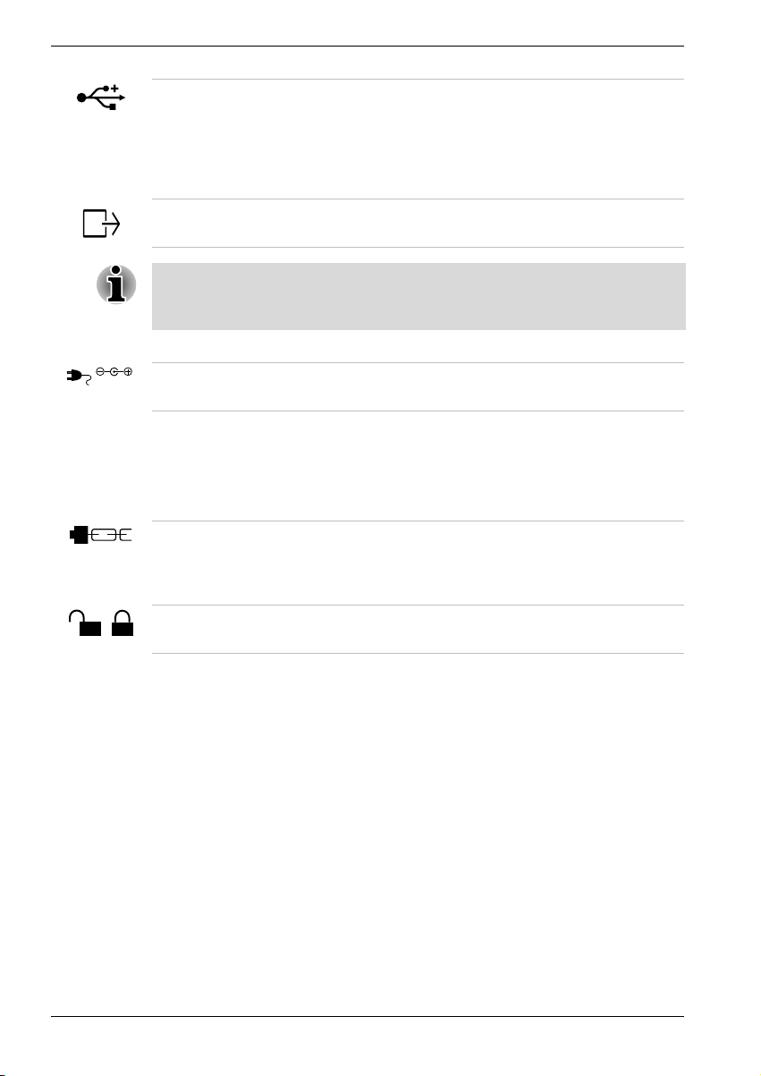
Ports
Universal Serial Bus
(USB 2.0)
External monitor 15-pin, analog VGA port supports VESA DDC2B
DVI A Digital Visual Interface (DVI) supports DVI-D
Depending on the computer connected to the Port Replicator, you may be
able to connect external monitors to the DVI port and the External monitor
port and display screens on both monitors at the same time.
Four Universal Serial Bus ports that comply with
the USB 2.0 standard. The ports also support
USB 1.1. If the computer does not support
USB 2.0, the Port Replicator supports up to
USB 1.1.
compatible functions.
type.
Communications
LAN The Port Replicator has support for Ethernet LAN
(10 megabits per second, 10BASE-T), Fast
Ethernet LAN (100 megabits per second,
100BASE-Tx) and Gigabit Ethernet LAN
(1000 megabits per second, 1000BASE-T). If the
computer does not support Gigabit Ethernet LAN
(1000BASE-T), the Port Replicator supports only
Ethernet LAN (10BASE-T) and Fast Ethernet
LAN (100BASE-Tx).
Security
Security lock slot Connects an optional security lock to anchor the
Port Replicator to a desk or other large object.
Computer lock This lock prevents disconnection of a computer
from the Port Replicator.
1-2 User’s Manual
Page 11

Special features
The following features are either unique to TOSHIBA computers or are
advanced features, which make the computer more convenient to use.
Specific functions depend on the type of computer, the operating system
and the application being used. Refer to the appropriate documentation for
details.
Wake On LAN When the Port Replicator is connected to a
Introduction
computer in standby or hibernation mode, this
feature turns on the power when a wake-up
signal is received from a LAN.
Wake Up (USB) When the Port Replicator is connected to a
computer in standby or hibernation mode, this
feature turns on the power when a wake-up
signal is received from a device connected to a
USB port.
User’s Manual 1-3
Page 12

Introduction
1-4 User’s Manual
Page 13
The Grand Tour
This chapter identifies the various components of your Port Replicator.
Front
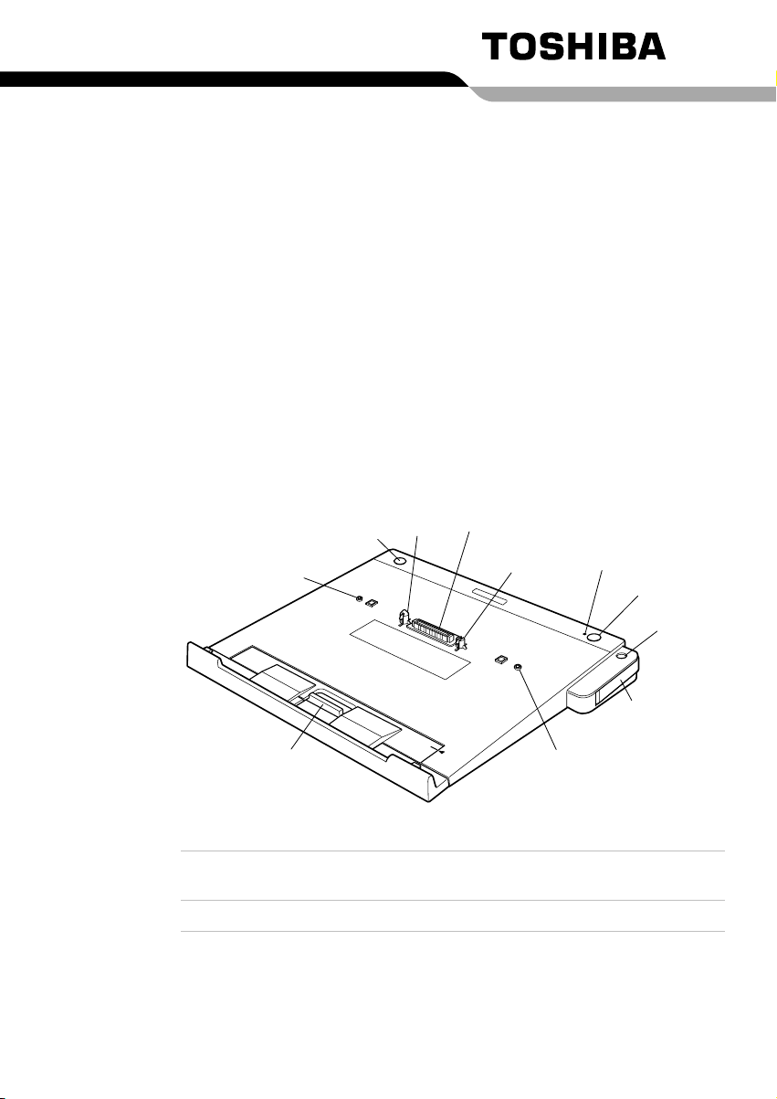
Figure 2-1 shows the Port Replicator’s front and right side.
Chapter 2
Power Switch
Pin
Slide Adjuster
Figure 2-1 The front and right side
Computer
connector
Hooks Hooks secure the computer to the Port Replicator.
User’s Manual 2-1
Hook
This is the computer interface. It connects directly
to the computer’s docking port.
Computer Connector
Hook
Pin
Eject LED
Eject Switch
Pen Stand
Eject Lever
Page 14
The Grand Tour
Pins Pins engage holes on the bottom of the computer
to ensure a proper connection.
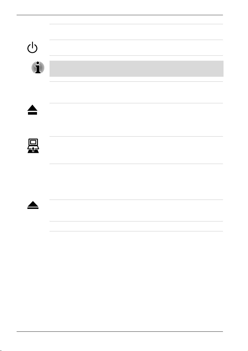
Power switch Press the power switch to turn the docked
computer’s power on and off.
Pressing the power switch has no effect if a computer is not connected to
the Port Replicator.
Slide adjuster If necessary, slide the adjuster forward or
backward so that it will be flush against the
computer.
Eject switch You can use the eject switch to enable hot
Eject LED Glows green during normal operation. When the
Right side
Refer to Figure 2-1 for the location of items on the Port Replicator’s right
side.
Eject lever This lever pops out for easy disconnection of the
Pen stand Pen stand holds your Tablet Pen.
undocking. Press the eject switch to begin the
computer’s disconnect sequence. When the eject
LED goes out it is safe to disconnect the
computer.
eject switch is pressed, the eject LED goes out
when the computer completes its disconnect
sequence.
computer from the Port Replicator. Refer to
Chapter 3 for disconnect procedures.
2-2 User’s Manual
Page 15
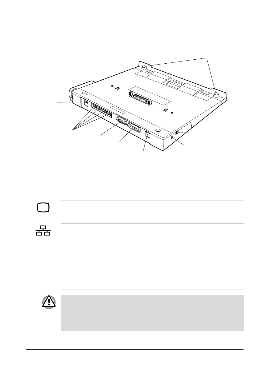
Back
DC IN15V
The Grand Tour
Figure 2-2 shows the Port Replicator’s back and left side.
Front Hook
USB Port
External Monitor Port
DVI Port
LAN Jack
Figure 2-2 The back and left side
Computer Lock
Security Lock Slot
Front hooks These Front hooks fit into holes at the front of the
computer to ensure a snug fit for the Port
Replicator.
External monitor
port
This 15-pin port lets you connect an external video
monitor. Note that the Resume feature is effective
with an external monitor.
LAN jack This jack lets you connect to a LAN. The Port
Replicator has support for Ethernet LAN
(10 megabits per second, 10BASE-T), Fast
Ethernet LAN (100 megabits per second,
100BASE-Tx) and Gigabit Ethernet
LAN(1000 megabits per second, 1000BASE-T).
If the computer does not support Gigabit Ethernet
LAN (1000BASE-T), the Port Replicator supports
only Ethernet LAN (10BASE-T) and Fast Ethernet
LAN (100BASE-Tx)
When the Port Replicator is connected to the computer, do not use the
External monitor port and the LAN jack of the computer. In the case using
these connecters both of the computer and the Port Replicator
simultaneously, it may harm the computer, the Port Replicator and/or data
contained in those.
User’s Manual 2-3
Page 16
The Grand Tour
DC IN 15V
Left side
Universal Serial
Bus (USB 2.0) ports
Four Universal Serial Bus ports are on the back.
The ports comply with the USB 2.0 standard The
ports also support USB 1.1. The number of the
USB ports of DMI information may differ from the
number of actual USB ports. For DMI information,
a USB port may be displayed as two ports.
DVI port Connect a DVI monitor. It supports DVI-D type
only.
Depending on the computer connected to the Port Replicator, you may be
able to connect external monitors to the DVI port and the External monitor
port and display screens on both monitors at the same time.
DC IN 15V The AC adaptor connects to this socket.
Refer to Figure 2-2 for the location of items on the Port Replicator’s left
side.
Security lock slot This slot lets you attach a security cable to the
Port Replicator to deter theft. Attach one end of
the cable to the Port Replicator and the other end
to a desk or other large object.
Computer lock It prevents disconnection of the computer from the
Port Replicator.
2-4 User’s Manual
Page 17
AC adaptor
The AC adaptor can automatically adjust to any voltage ranging from 100 to
240 volts and to a frequency of either 50 or 60 hertz, enabling you to use
the Port Replicator in almost any country/region.
The adaptor converts AC power to DC power and reduces the voltage
supplied to the Port Replicator.
The Grand Tour
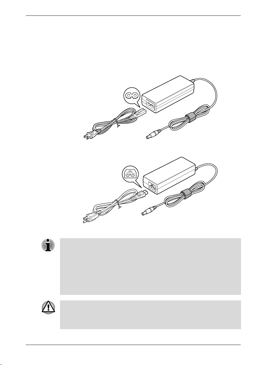
Figure 2-3 The AC adaptor (2-pin plug)
Figure 2-4 The AC adaptor (3-pin plug)
1. The Universal AC Adaptor and power cord bundled with this product
may differ depending on the product model. Depending on the model, a
2-pin plug or 3-pin plug set of the above may be bundled.
2. Do not use a 3-pin to 2-pin conversion plug.
3. The supplied power cord conforms to safety rules and regulations in
the region the product is bought and should not be used outside this
region. For use in other regions, please buy power cords that conform
to safety rules and regulations in the particular region.
Always use the Toshiba AC adaptor that was provided with this product or
use Toshiba recommended alternate models to avoid any risk of fire or
other damage to the PC. Use of an incompatible AC adaptor could cause
fire or damage to the PC possibly resulting in serious injury.
User’s Manual 2-5
Page 18

The Grand Tour
2-6 User’s Manual
Page 19

Connections
The Port Replicator is designed to ensure a secure connection by a few
simple operations.
The system supports warm docking and undocking. Do not disconnect the
Port Replicator from the computer while an application is running.
Connecting the Port Replicator
When the Port Replicator is connected to the computer, do not use the
ports of the computer. In the case using ports both of the computer and the
Port Replicator simultaneously, it may harm the computer, the Port
Replicator and/or data contained in those.
To connect the Port Replicator, follow the steps below.
1. Check the distance from the front of the computer to the Port Replicator
connector. If necessary, slide the adjuster forward so that it will be flush
against the computer. The computer corresponding to the position of
the adjuster is as follows. Refer to www.Toshiba.com about future
models being released.
SLIDE position from #1-#12
Chapter 3
Position #1-#12 product name
,
5
User’s Manual 3-1
,
PORTEGE M400
Page 20
Connections
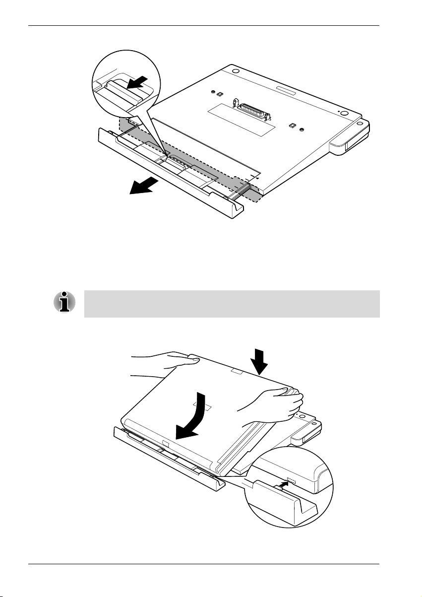
Figure 3-1 Slide the adjuster
2. Remove all cables from your computer’s ports.
3. Attach the cables to the Port Replicator’s ports.
4. Align the front holes of the PC with the front hooks of the Port Replicator
while placing the PC on the Port Replicator
Align the computer's hook and the hook on the left side of the Port
Replicator.
5. To ensure a firm connection, press down on the computer until you hear
the latch click.
Figure 3-2 Connecting a notebook to the Port Replicator
3-2 User’s Manual
Page 21
Connecting the AC adaptor
To supply AC power to the computer, connect the AC adaptor according to
the steps below.
Only use the AC adapter supplied with this Port Replicator. Use of any
incompatible adaptor could damage your computer. TOSHIBA assumes no
liability for any damage caused by use of an incompatible adaptor.
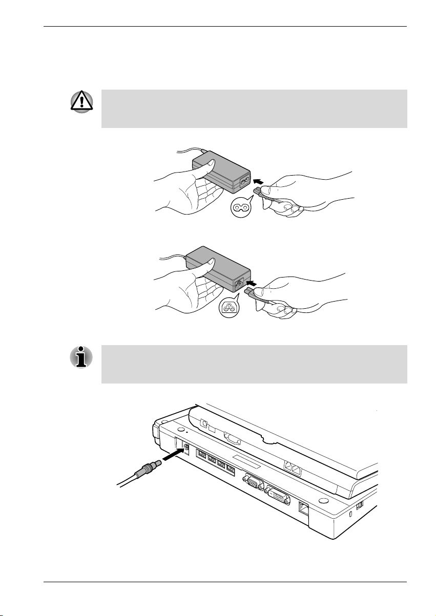
1. Connect the power cord to the AC adaptor.
Figure 3-3 Connecting the power cord to the AC adaptor (2-pin plug)
Connections
Figure 3-4 Connecting the power cord to the AC adaptor (3-pin plug)
The Universal AC Adaptor and power cord bundled with this product may
differ depending on the product model. Depending on the model, a 2-pin
plug or 3-pin plug set of the above may be bundled.
2. Connect the AC adaptor to the Port Replicator.
Figure 3-5 Connecting the AC adaptor
3. Connect the power plug to a wall outlet.
User’s Manual 3-3
Page 22
Connections
When you connect the AC adaptor to the Port Replicator, always follow the
steps in the exact order as described above. Connecting the power cable
to a live electrical outlet should be the last step, otherwise the adaptor DC
output plug could hold an electrical charge and cause an electrical shock
or minor bodily injury when touched. As a general safety precaution, avoid
touching any metal parts.
Disconnecting the Port Replicator
To disconnect the Port Replicator, follow the steps below and save all your
work first.
1. Set the computer lock to the unlock position.
2. Make sure you perform one of the following:
■ Perform any software disconnect operation required by the
operating system.
■ Turn off the computer’s power in any mode: boot, suspend or
hibernation.
■ Press the eject switch.
Make sure the Eject LED is out. Do not try to disconnect the computer
while the Eject LED is glowing.
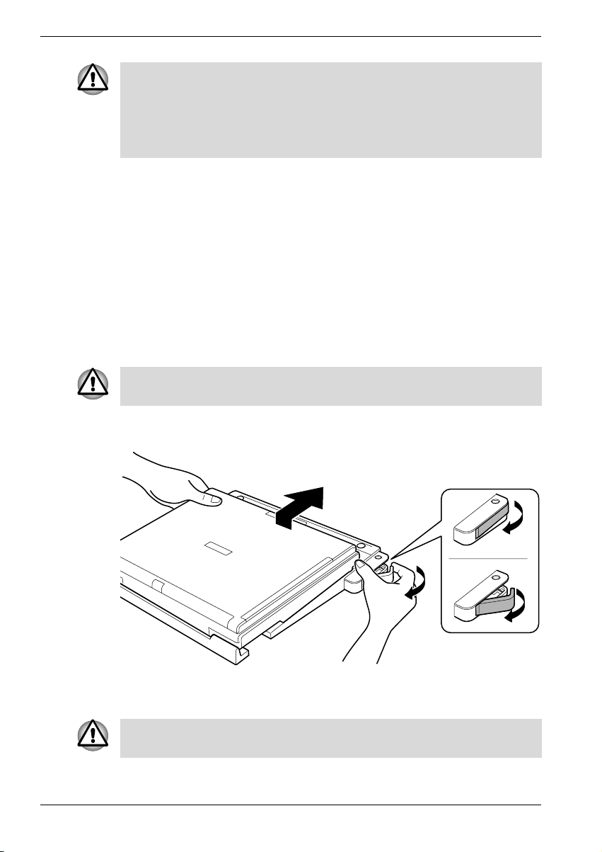
3. To disconnect the computer, pull the eject lever towards you while
sliding the computer backwards.
Figure 3-6 Disconnecting a notebook from the Port Replicator
4. Lift off the computer.
Do not lift up the computer without sliding the computer backwards,
otherwise the Port Replicator’s hooks may be damaged.
3-4 User’s Manual
Page 23
Security lock
A security lock enables you to anchor the Port Replicator to a desk or
another heavy object to help prevent unauthorized removal of the Port
Replicator. A computer lock can be set to engage the Port Replicator’s
security lock so that the computer cannot be disconnected from the Port
Replicator while the security lock is secured.
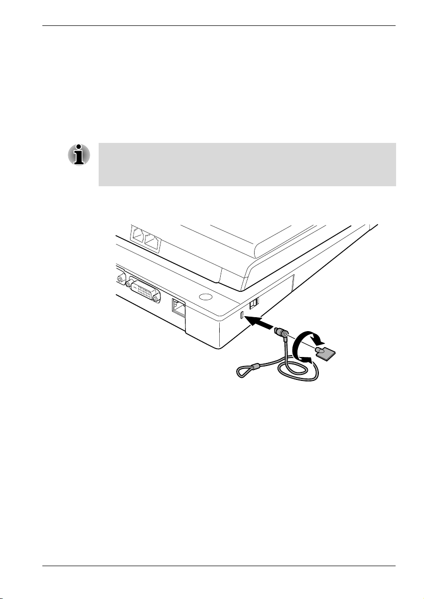
1. Attach one end of a cable to a desk or another heavy object.
2. Set the computer lock.
There are two positions for the computer lock.
Back: You can disconnect the computer from the Port Replicator.
Forward: You cannot disconnect the computer from the Port Replicator.
3. Insert the other end into the Port Replicator’s security lock slot.
4. Secure it with the key.
Connections
Figure 3-7 Security lock
User’s Manual 3-5
Page 24

Connections
3-6 User’s Manual
Page 25
Communications
A jack enables easy connection to a local-area network without the need of
a PC card or other adaptor.
When you use your computer with the Port Replicator connected to it, do
not attach any cables from external devices to your computer. If these
cables are connected to the ports of your computer, the ports of the Port
Replicator may not work as expected.
LAN
The Port Replicator supports Ethernet LAN, Fast Ethernet LAN and Gigabit
Ethernet LAN. If the computer does not support Gigabit Ethernet LAN
(1000BASE-T), the Port Replicator supports only Ethernet LAN (10BASE-T)
and Fast Ethernet LAN (100BASE-Tx).
Do not install or remove an optional memory module while Wake-up on
LAN is enabled.
Chapter 4
The Wake-up on LAN function consumes power even when the system is
off. Leave the AC adaptor connected while using this feature.
LAN cable types
The computer must be configured properly before connecting to a LAN.
Logging onto a LAN using the computer’s default settings could cause a
malfunction in LAN operation. Check with your LAN administrator
regarding set-up procedures.
User’s Manual 4-1
Page 26
Communications
Connecting
If you are using Gigabit Ethernet LAN (1000 megabits per second,
1000BASE-T), be sure to connect with a CAT5 cable or a CAT5E cable.
(A CAT5E cable is recommended.) You cannot use a CAT3 cable.
If you are using Fast Ethernet LAN (100 megabits per second, 100BASE-TX),
be sure to connect with a CAT5 cable. You cannot use a CAT3 cable.
If you are using Ethernet LAN (10 megabits per second, 10BASE-T), you
can connect with either a CAT5 or a CAT3.
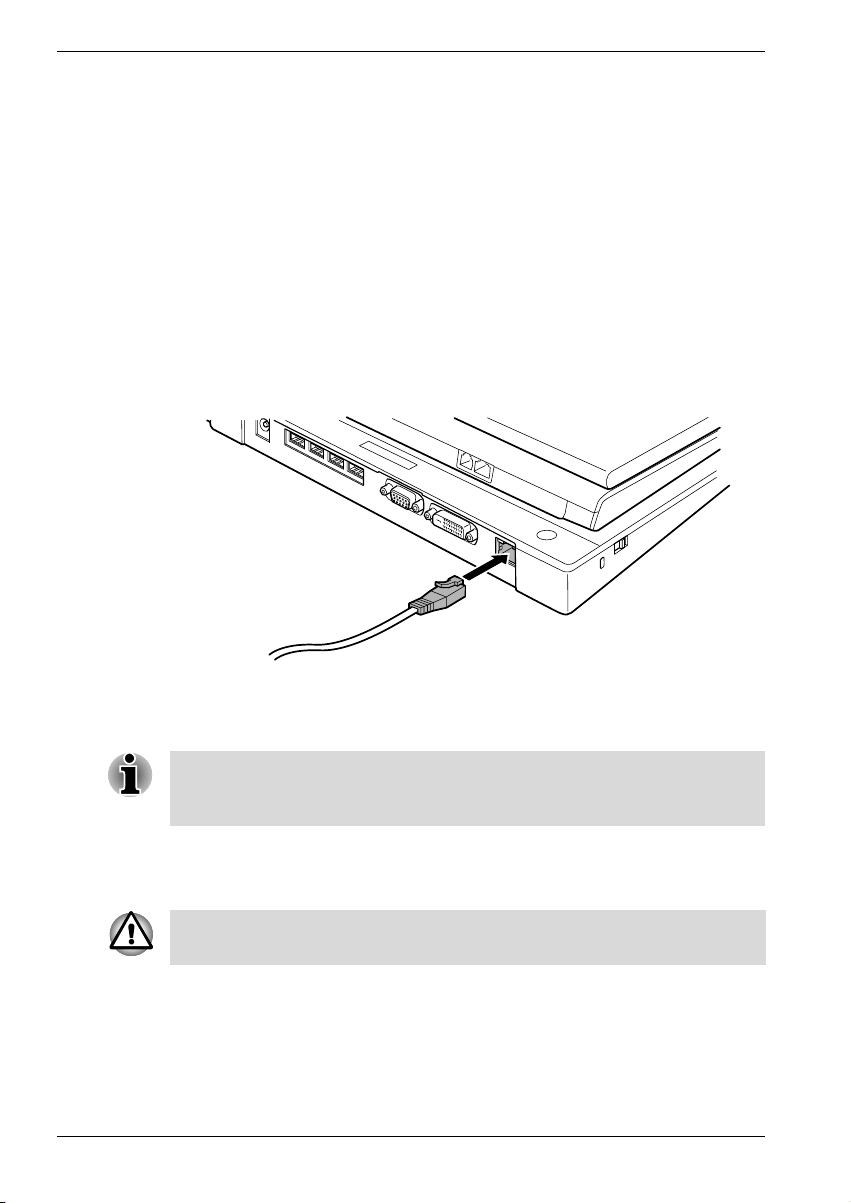
To connect the LAN cable, follow the steps below.
1. Save all your work. Turn off the power to the computer and to all
external devices connected to the Port Replicator and to the computer.
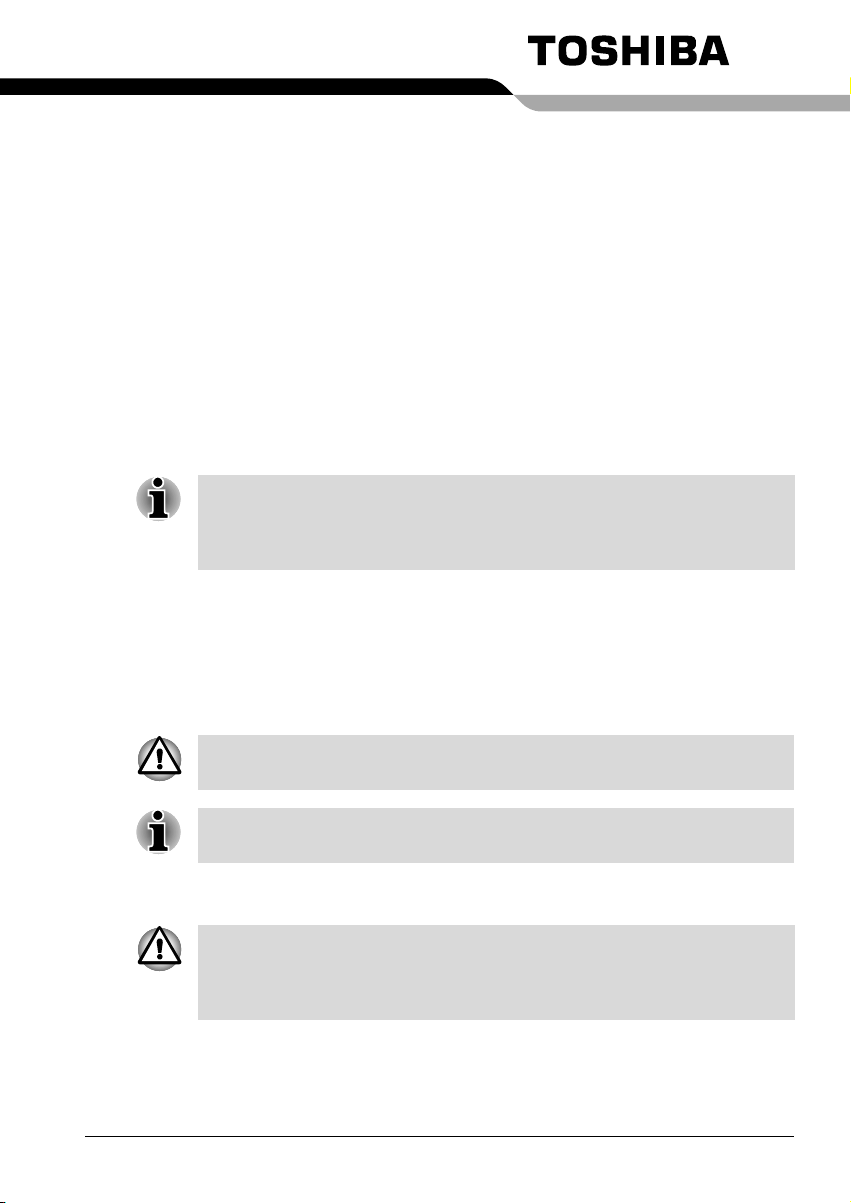
2. Plug one end of the cable into the Port Replicator’s LAN jack.
Press gently until you hear the latch click into place.
Figure 4-2 Connecting the LAN cable
3. Plug the other end of the cable into a LAN hub connector. Check with
your LAN administrator before connecting to a hub.
When the computer is exchanging data with the LAN, the LAN Active
indicator glows orange. When the computer is connected to a LAN hub but
is not exchanging data, the Link indicator glows green.
Disconnecting
To disconnect the LAN cable, follow the steps below.
Before you disconnect the LAN cable, make sure the computer is not
accessing data. The green LED will glow when it is safe to disconnect.
1. Pinch the lever on the connector in the Port Replicator and pull out the
connector.
2. Disconnect the cable from the LAN hub in the same manner.
Check with your LAN administrator before disconnecting from the hub.
4-2 User’s Manual
Page 27
Universal Serial Bus (USB 2.0) ports
A USB mouse, keyboard, and/or diskette connected to the Port Replicator
via any connection other than a first tier hub, will not work until the OS has
started.
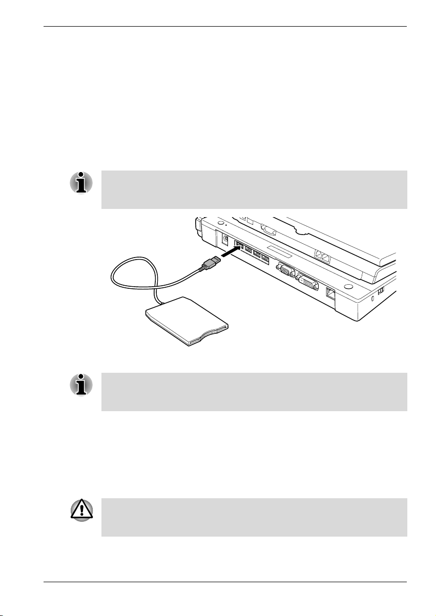
Connecting and using the USB Diskette Drive
A 3 1/2" diskette drive connects to the Port Replicator’s USB port.
It accommodates 1.44-megabyte or 720-kilobyte diskettes.
To connect the drive, plug the diskette drive connector into a USB port.
Refer to Figure 4-3.
Make sure the connector is upside down and properly aligned with the
socket. Do not try to force the connection, doing so can damage the
connecting pins.
Communications
Figure 4-3 Connecting the USB diskette drive to the computer
If you connect the diskette drive after turning on the computer, it will take
several seconds for the computer to recognize the drive. Do not disconnect
and reconnect before this time has elapsed.
Disconnecting the USB diskette drive
When you have finished using the diskette drive, save all your work before
disconnecting the USB Diskette Drive follow the procedures below to
disconnect it:
1. Wait for the indicator light to go out to make sure all diskette activity has
stopped.
If you disconnect the diskette drive or turn off the power while the computer
is accessing the drive, you may lose data or damage the diskette or the
drive.
2. Pull the diskette drive connector out of the USB port.
User’s Manual 4-3
Page 28

Communications
4-4 User’s Manual
Page 29

Troubleshooting
This chapter provides tips to correct problems, should any occur. It also
describes how to contact TOSHIBA should you encounter problems that
you cannot resolve.
Before you call Toshiba, please read the Before you call section in this
chapter. Also refer to the general troubleshooting advice at the beginning of
the Troubleshooting chapter in your computer’s user manual.
This chapter refers to the HW Setup diagnostic program. Some computer
models do not support all of these programs. Refer to your computer’s user
manual.
Hardware checklist
This section discusses problems caused by your Port Replicator’s
hardware. Basic problems may occur in the following areas:
■ AC power
■ Power switch
■ Overheating power down
Chapter 5
■ Monitor (External/DVI)
■ USB
■ LAN
User’s Manual 5-1
Page 30

Troubleshooting
AC power
Power switch
If your computer is connected to the AC adaptor and you cannot turn on the
computer, check your computer’s DC IN 15V indicator.
Problem Procedure
AC adaptor doesn’t
power the computer
(Your computer’s DC IN
15V indicator does not
glow green)
Problem Procedure
Check the connections. Make sure the cord is
firmly connected to the computer and a power
outlet.
Check the condition of the cord and terminals.
If the cord is frayed or damaged, replace it. If the
terminals are soiled, wipe them with cotton or a
clean cloth.
If the AC adaptor still does not power the
computer, contact your dealer.
The computer does not
turn on when you press
the power switch
Connect the AC adaptor and try again to turn on
the computer.
If the computer still does not turn on, refer to the
sections Overheating power down and AC
power.
Overheating power down
If the computer’s internal temperature becomes too high, the computer will
automatically enter Resume mode and shut down.
Problem Procedure
Computer enters
Resume mode and
shuts down
Computer shuts down
and its DC IN 15V
indicator is flashing
green
Leave the computer off until its interior reaches
room temperature.
If the computer has reached room temperature
and still does not start, or if it starts but shuts
down quickly, contact your dealer.
Indicates a problem with the heat dispersal
system. Please contact your dealer.
5-2 User’s Manual
Page 31

Monitor (analog external monitor/DVI monitor)
Refer also to your computer user’s manual and to your monitor’s
documentation.
Problem Procedure
Monitor does not turn onMake sure that the monitor’s power switch is on.
Confirm that the external monitor’s power cable
is plugged into a working power outlet.
No display Try adjusting the contrast and brightness controls
on the monitor.
Press hotkeys Fn + F5 to change the display
priority and make sure it is not set for the internal
display.
Troubleshooting
Display error occurs Check that the cable connecting the monitor to
the computer is attached firmly.
If problems persist, contact your dealer.
USB
Refer also to your USB device’s documentation.
Problem Procedure
USB device does not
work
Check for a firm cable connection between the
USB ports on the Port Replicator and the USB
device.
Make sure the USB device drivers are properly
installed. Refer to your Microsoft Windows
documentation for more information.
If you are using an operating system that does
not support USB, you can still use a USB mouse
and/or USB keyboard. If these devices do not
work, make sure the USB Legacy Emulation item
in HW Setup is set to Enabled.
This feature works only for mouse and keyboard.
Also, note that the mouse and keyboard must be
connected before you boot the computer.
A USB mouse, keyboard, and/or diskette
connected to the Port Replicator via any
connection other than a first tier hub, will not
work until the OS has started.
If problems persist, contact your dealer.
User’s Manual 5-3
Page 32

Troubleshooting
LAN
Problem Procedure
Cannot access LAN Contact the system administrator or if the
TOSHIBA support
If you require any additional help using your computer or if you are having
problems operating the Port Replicator, you may need to contact TOSHIBA
for additional technical assistance.
Before you call
Some problems that you experience may be related to software or the
operating system. Before you contact TOSHIBA, please investigate your
problem using the following resources:
■ Review troubleshooting sections in the documentation for your
computer, software and peripheral devices.
■ If a problem occurs when you are running software applications, consult
the software documentation for troubleshooting suggestions. Call the
software company’s technical support for assistance.
■ Consult the dealer you purchased your computer and/or software from.
They are your best sources for current information and support.
problem persists, contact your dealer.
Where to write
If you are still unable to solve the problem and suspect that it is hardware
related, write to TOSHIBA at the nearest location listed on the next page.
5-4 User’s Manual
Page 33

Troubleshooting
Outside of Europe
Australia
TOSHIBA Australia Pty. Ltd.
Information Systems Division
84-92 Talavera Road
North Ryde N.S.W. 2113
Sydney
Canada
TOSHIBA of Canada Ltd.
191 McNabb Street,
Markham, Ontario
L3R 8H2
China
TOSHIBA Personal Computer &
Network (Shanghai) Co., Ltd.
43F, Hong Kong New World Tower,
No. 300 Huaihai Zhong Road,
Shanghai, P. R. China 200021
Singapore
TOSHIBA Singapore Pte. Ltd.
438B Alexandra Road #06-01
Alexandra Technopark
Singapore 119968
United States of America
TOSHIBA America Information
Systems, Inc.
9740 Irvine Boulevard
Irvine, California 92618
USA
In Europe
Germany & Austria
TOSHIBA Europe (I.E.) GmbH
Geschäftsbereich,
Deutschland-Österreich
Hammfelddamm 8,
D-41460 Neuss, Germany
France
TOSHIBA Systèms France S.A.
7, Rue Ampère B.P. 131,
92804 Puteaux Cedex
Netherlands
TOSHIBA Information Systems,
Benelux B.V.
Rivium Boulevard
41 2909 LK Capelle a/d IJssel
Spain
TOSHIBA Information Systems,
ESPAÑA
Parque Empresarial San Fernando
a
Edificio Europa, l
Planta,
Escalera A 28830 Madrid
United Kingdom
TOSHIBA Information Systems
(U.K.) Ltd.
TOSHIBA Court
Weybridge Business Park
Addlestone Road
Weybridge, Surrey KT15 2UL
The Rest of Europe
TOSHIBA Europe (I.E.) GmbH
Geschäftsbereich,
Deutschland-Österreich
Hammfelddamm 8,
D-41460 Neuss, Germany
User’s Manual 5-5
Page 34

Troubleshooting
5-6 User’s Manual
Page 35

Specifications
This appendix summarizes the Port Replicator’s technical specifications.
Physical Dimensions
Weight XXX grams
Size 322 (w) x 272 (d) x 7.9/28.5 (h) millimeters
Environmental Requirements
Conditions Ambient temperature Relative humidity
Operating 5°C (41°F) to 35°C (95°F) 20% to 80%
Non-operating -20°C (-4°F) to 65°C (149°F) 10% to 95%
Thermal Gradient 20°C per hour maximum
Wet-bulb temperature 26°C maximum
Conditions Altitude (from sea level)
Operating -60 to 3,000 meters
Non-operating -60 to 10,000 meters maximum
Appendix A
Power Requirements
AC adaptor 100 - 240 volts AC
50 or 60 hertz (cycles per second)
15 VDC
6.0 amperes
User’s Manual A-1
Page 36

Specifications
A-2 User’s Manual
Page 37

Appendix B
AC Power Cord and Connectors
The power cord’s AC input plug must be compatible with the various
international AC power outlets and the cord must meet the standards for
the country/region in which it is used. All cords must meet the following
specifications:
Length: Minimum 2 meters
Wire size: Minimum 0.75 mm
Current rating: Minimum 2.5 amperes
Voltage rating: 125 or 250 VAC
(depending on country/region’s power
Certification agencies
U.S. and Canada: UL listed and CSA certified
No. 18 AWG, Type SVT or SPT-2
Australia: AS
Japan: DENANHO
Europe:
Austria: OVE Italy: IMQ
Belgium: CEBEC The Netherlands: KEMA
Denmark: DEMKO Norway: NEMKO
Finland: FIMKO Sweden: SEMKO
France: LCIE Switzerland: SEV
Germany: VDE United Kingdom: BSI
2
standards)
User’s Manual B-1
Page 38

AC Power Cord and Connectors
In Europe, two conductors power cord must be VDE type, H05VVH2-F or
H03VVH2-F and for three conductors power cord must be VDE type,
H05VV-F.
For the United States and Canada, two pin plug configuration must be a
2-15P (250V) or 1-15P (125V) and three pin plug configuration must be
6-15P (250V) or 5-15P (125V) as designated in the U.S. National Electrical
code handbook and the Canadian Electrical Code Part II.
The following illustrations show the plug shapes for the U.S.A. and Canada,
the United Kingdom, Australia and Europe.
USA
United Kingdom
UL approved
Australia Europe
AS approved
Approved by the
appropriate agency
Canada
CSA approved
BS approved
B-2 User’s Manual
Page 39

Index
A
AC adaptor
connecting
specifications
3-3
2-5
C
CAT3 CAT5 CAT5E cables 4-2
Computer lock
using
1-2
3-5
D
DC-IN 15V 2-4
1-2
DVI
E
Eject LED 2-2
Eject lever
Eject switch
Equipment checklist
Ethernet
2-2
2-2
1-1
1-2, 4-1
L
LAN 1-2
cable types
connecting
disconnecting
Ethernet usage
features
problems, see Troubleshooting
using
4-1
4-2
4-2
4-2
4-1
4-2
P
Port Replicator
connecting
disconnecting
3-1
3-4
S
Security lock slot 1-2, 2-4
3-5
using
T
TOSHIBA support 5-4
Troubleshooting
AC power
hardware checklist
LAN
monitor
overheating power down
power switch
USB
5-2
5-1
5-4
5-3
5-2
5-3
U
Universal Serial Bus 1-2, 4-3
problems, see Troubleshooting
5-2
M
Monitor external 2-3
problems, see Troubleshooting
User’s Manual Index-1
Page 40

Index
Index-2 User’s Manual
Page 41

Manuel de l’utilisateur
Réplicateur de ports
Page 42

Copyright
© 2006 par TOSHIBA Corporation. Tous droits réservés. Selon la loi du
Copyright, le présent manuel ne peut pas être reproduit, sous toute forme
que ce soit, sans l’autorisation écrite préalable de TOSHIBA. TOSHIBA
n’engage aucunement sa responsabilité quant à l’utilisation qui peut être
faite des informations contenues dans le présent ouvrage.
Manuel de l’utilisateur du réplicateur de ports TOSHIBA Express Port
Replicator
Première édition : février 2006
Responsabilités
Le présent manuel a fait l’objet d’une procédure de révision et de
validation. Les instructions et les descriptions qu’il comporte sont correctes
pour le réplicateur de ports TOSHIBA Express Port Replicator lors de la
rédaction du présent manuel. Cependant, les ordinateurs et les manuels
ultérieurs peuvent être modifiés sans préavis. TOSHIBA n’assume aucune
responsabilité pour les dommages liés directement ou indirectement à des
erreurs, des omissions ou des incohérences entre l’ordinateur et le manuel.
Marques
Windows est une marque déposée de Microsoft Corporation.
Ethernet est une marque déposée et Fast Ethernet et Gigabit Ethernet sont
des marques de Xerox Corporation.
D’autres marques commerciales et marques déposées ne figurant pas
dans la liste peuvent avoir été mentionnées dans ce manuel.
Informations FCC
Nom du produit : Réplicateur de ports Express Port Replicator
Modèle : PA3508*
ii Manuel de l’utilisateur
Page 43

Notice FCC « Déclaration de conformité »
Cet équipement a été testé et est conforme aux limites imposées aux
appareils numériques de classe B, conformément à la section 15 des règles
de la FCC. Ces limites ont été conçues pour protéger les installations
domestiques contre les interférences néfastes. Cet équipement génère,
utilise et émet de l’énergie sous forme de fréquences radio et, en cas de nonrespect des instructions d’installation et d’utilisation, risque de provoquer des
interférences. Il n’existe aucune garantie contre ces interférences. En cas
d’interférences radio ou télévisuelles, pouvant être vérifiées en mettant hors,
puis sous tension l’équipement, l’utilisateur peut tenter de résoudre le
problème de l’une des façons suivantes :
■ Réorienter ou déplacer l’antenne de réception ;
■ Éloigner l’équipement du poste de réception ;
■ Brancher l’équipement sur une prise appartenant à un circuit différent
de celui du poste de réception ;
■ Consulter le revendeur ou un technicien radio/TV qualifié.
AVERTISSEMENT : Seuls des périphériques conformes aux limites
définies par la classe B de la FCC peuvent être connectés à cet
équipement. Toute connexion à des périphériques non conformes ou non
recommandés par TOSHIBA risque d’entraîner des interférences radio et
télévisuelles. Utilisez des câbles blindés entre les périphériques externes
et les ports écran externe, DVI ou USB. Les changements ou les
modifications apportées à cet équipement qui ne sont pas approuvés
expressément par TOSHIBA, ou les parties autorisées par TOSHIBA,
peuvent entraîner la révocation du droit d’utilisation de cet équipement.
Conditions FCC
Le présent périphérique est conforme à la section 15 des règles de la FCC.
Son utilisation est assujettie aux deux conditions suivantes :
1. Ce périphérique ne doit pas provoquer d’interférences néfastes.
2. Ce périphérique doit tolérer les interférences reçues, ce qui inclut les
interférences qui risquent de provoquer un dysfonctionnement.
Contact
Adresse : TOSHIBA America Information Systems, Inc.
9740 Irvine Boulevard
Irvine, CA 92618-1697
Téléphone : (949) 583-3000
Manuel de l’utilisateur iii
Page 44

Déclaration européenne de conformité
TOSHIBA déclare que le produit : PA3508* est conforme aux normes
suivantes :
Informations supplémentaires « Ce produit est conforme aux dispositions
des directives Basse Tension 73/23/EEC et à
la directive CEM 89/336/EEC. »
Le présent produit porte le label CE conformément aux directives
européennes. La partie responsable de l’homologation CE est TOSHIBA
Europe, Hammfelddamm 8, 41460 Neuss, Allemagne.
Informations sur la classe B VCCI
Informations spécifiques aux pays de l’Union
Européenne
L’utilisation de ce symbole indique que ce produit ne pourra pas être traité
en tant que déchet ordinaire à la fin de son cycle de vie. En disposant de ce
produit de façon responsable, vous participerez à la protection de
l’environnement et de la santé. Pour plus d’informations sur le recyclage de
ce produit, contactez votre mairie ou le service de collecte des déchets,
voire le magasin où vous avez acheté ce produit.
iv Manuel de l’utilisateur
Page 45

Table des matières
Préface
Sommaire . . . . . . . . . . . . . . . . . . . . . . . . . . . . . . . . . . . . . . . . . . . . . . . . vii
Conventions . . . . . . . . . . . . . . . . . . . . . . . . . . . . . . . . . . . . . . . . . . . . . viii
Chapitre 1 Introduction
Liste de vérification de l’équipement . . . . . . . . . . . . . . . . . . . . . . . . . 1-1
Caractéristiques . . . . . . . . . . . . . . . . . . . . . . . . . . . . . . . . . . . . . . . . . . 1-1
Fonctions spéciales . . . . . . . . . . . . . . . . . . . . . . . . . . . . . . . . . . . . . . . 1-3
Chapitre 2 Présentation
Vue avant. . . . . . . . . . . . . . . . . . . . . . . . . . . . . . . . . . . . . . . . . . . . . . . . 2-1
Face droite . . . . . . . . . . . . . . . . . . . . . . . . . . . . . . . . . . . . . . . . . . . . . . 2-2
Vue arrière. . . . . . . . . . . . . . . . . . . . . . . . . . . . . . . . . . . . . . . . . . . . . . . 2-3
Vue de gauche . . . . . . . . . . . . . . . . . . . . . . . . . . . . . . . . . . . . . . . . . . . 2-4
Adaptateur secteur. . . . . . . . . . . . . . . . . . . . . . . . . . . . . . . . . . . . . . . . 2-5
Chapitre 3 Connexions
Connexion du réplicateur de ports . . . . . . . . . . . . . . . . . . . . . . . . . . . 3-1
Connexion de l’adaptateur secteur. . . . . . . . . . . . . . . . . . . . . . . . . . . 3-3
Déconnexion du réplicateur de ports . . . . . . . . . . . . . . . . . . . . . . . . . 3-4
Prise de sécurité. . . . . . . . . . . . . . . . . . . . . . . . . . . . . . . . . . . . . . . . . . 3-5
Chapitre 4 Communications
Carte LAN . . . . . . . . . . . . . . . . . . . . . . . . . . . . . . . . . . . . . . . . . . . . . . . 4-1
Ports USB (USB 2.0). . . . . . . . . . . . . . . . . . . . . . . . . . . . . . . . . . . . . . . 4-3
Chapitre 5 Dépannage
Liste de vérification du matériel . . . . . . . . . . . . . . . . . . . . . . . . . . . . . 5-1
Assistance TOSHIBA . . . . . . . . . . . . . . . . . . . . . . . . . . . . . . . . . . . . . . 5-4
Annexe A Spécifications
Annexe B Cordons et connecteurs d’alimentation
Index
Manuel de l’utilisateur v
Page 46

vi Manuel de l’utilisateur
Page 47

Préface
Merci d’avoir choisi le réplicateur de ports TOSHIBA Express Port Replicator.
Cette interface permet d’accroître les capacités d’extension de votre
ordinateur.
Le présent manuel indique comment installer et utiliser le réplicateur de
ports Express Port Replicator, comment résoudre les incidents et comporte
des consignes de sécurité. Il apporte également des informations détaillées
sur les fonctions LAN, ce qui inclut Ethernet®, Fast Ethernet™ et Gigabit
Ethernet™.
Sommaire
Ce manuel est composé de cinq chapitres et deux annexes et un index.
Le chapitre 1, Introduction, présente les principales caractéristiques du
réplicateur de ports et de l’adaptateur secteur universel.
Le chapitre 2, Présentation, traite des périphériques et de leurs
composants.
Le chapitre 3, Connexions, indique comment connecter l’ordinateur au
réplicateur de ports et le déconnecter.
Le chapitre 4, Communications, indique comment utiliser les périphériques
suivants : réseau, USB 2.0.
Le chapitre 5, Résolution des incidents, permet de résoudre les problèmes
courants.
Les annexes présentent les principales caractéristiques techniques du
réplicateur de ports.
L’index vous permet d’accéder rapidement aux informations contenues
dans ce manuel.
Manuel de l’utilisateur vii
Page 48

Préface
Conventions
Le présent manuel utilise les formats ci-après pour décrire, identifier et
mettre en évidence les termes et les procédures.
Abréviations
La première fois qu’elles apparaissent dans le texte et pour des raisons de
clarté, les abréviations sont indiquées entre parenthèses après leur définition.
Par exemple : Read Only Memory (ROM).
Icônes
Les icônes identifient les ports, les boutons et autres parties du réplicateur
de ports. Le panneau de voyants utilise également des icônes pour
identifier des composants.
Messages
Les messages présentés dans ce manuel fournissent des informations
importantes et sont destinés à attirer votre attention sur un point important.
Vous distinguerez deux types de message :
Attention ! Ces messages vous mettent en garde contre une utilisation ou
une manipulation incorrecte de votre ordinateur risquant d’engendrer la
perte de données ou d’endommager votre matériel.
Prière de lire les messages. Les remarques sont constituées de conseils
ou d’avertissements qui permettent d’utiliser votre matériel de manière
optimale.
viii Manuel de l’utilisateur
Page 49

Chapitre 1
Introduction
Vous trouverez, dans ce chapitre, une liste de vérification de l’équipement.
Elle identifie les caractéristiques et les accessoires du duplicateur de ports.
Liste de vérification de l’équipement
Déballez avec précautions le duplicateur de ports. Conservez le carton et
l’emballage pour une utilisation ultérieure.
Assurez-vous que tous les éléments suivants sont présents :
■ Réplicateur de ports Express Port Replicator
■ Adaptateur secteur universel et cordon d’alimentation
■ Manuel de l’utilisateur du réplicateur de ports Express Port Replicator
■ Guide d’utilisation des produits Toshiba
Caractéristiques
Lorsque le réplicateur de ports est connecté à l’ordinateur, vous pouvez
exploiter les fonctionnalités réseau (Ethernet
Ethernet™) et USB 2.0. Lorsque le réplicateur de ports est connecté à
l’ordinateur, n’utilisez pas la prise LAN de l’ordinateur. En outre, lorsque la
prise réseau du réplicateur de ports doit être utilisée selon un mode
compatible avec les fonctionnalités réseau de l’ordinateur.
Il se connecte directement à l’interface d’accueil située sur le dessous de
l’ordinateur. L’adaptateur secteur permet de connecter le duplicateur de
ports à une source d’alimentation.
Manuel de l’utilisateur 1-1
®
, Fast Ethernet™ et Gigabit
Page 50

Introduction
Alimentation
Adaptateur secteur L’adaptateur secteur universel alimente le
système et recharge les batteries lorsque ces
dernières s’épuisent. Il dispose d’un cordon
amovible avec un connecteur de 2 ou 3 broches.
Du fait qu’il est universel, l’adaptateur peut
recevoir des tensions comprises entre 100 et
240 volts ; le courant de sortie varie cependant
d’un modèle à l’autre. L’utilisation d’un modèle
inapproprié risque d’endommager le réplicateur
de ports.
Ports
USB 2.0 Quatre ports USB compatibles à la norme
USB 2.0. Ces ports prennent également en
charge USB 1.1. Lorsque l’ordinateur ne prend
pas en charge USB 2.0, le duplicateur de ports
applique le mode USB 1.1.
Ecran externe Port 15 broches (VGA analogique) gérant les
fonctions compatibles VESA DDC2B.
DVI Le port DVI (Digital Visual Interface - Interface
visuelle numérique) prend en charge le type DVI-D.
Selon l’ordinateur connecté au Duplicateur de ports, vous pouvez
connecter des écrans externes aux ports DVI et Ecran externe et afficher
des données sur ces deux écrans.
Communications
Carte LAN Le duplicateur de ports prend en charge Ethernet
LAN (10 mégabits par seconde, 10BASE-T) de
façon standard, Fast Ethernet LAN
(100 mégabits par seconde, 100BASE-Tx) et
Gigabit Ethernet LAN (1 000 mégabits par
seconde, 1000BASE-T). Lorsque l’ordinateur ne
prend pas en charge Gigabit Ethernet LAN
(1000BASE-T), le duplicateur de ports applique
le mode Ethernet LAN (10BASE-T) et Fast
Ethernet LAN (100BASE-Tx).
1-2 Manuel de l’utilisateur
Page 51

Sécurité
Introduction
Prise de sécurité Permet d’installer un verrou de sécurité en option
Verrou de
l’ordinateur
Fonctions spéciales
Les fonctions suivantes sont soit des fonctions spécifiques aux ordinateurs
TOSHIBA soit des fonctions évoluées qui simplifient leur utilisation.
Les fonctions spécifiques dépendent du type d’ordinateur, du système
d’exploitation et de l’application utilisée. Reportez-vous à la documentation
appropriée pour plus de détails.
Wake On LAN Lorsque le duplicateur de ports est connecté à un
Wake Up (USB) Lorsque le duplicateur de ports est connecté à un
pour attacher le duplicateur de ports à un objet
volumineux.
Ce verrou permet de lier le duplicateur de ports à
l’ordinateur.
ordinateur en mode Veille ou Veille prolongée,
cette fonction permet de rétablir l’alimentation sur
réception d’un signal du LAN.
ordinateur en mode Veille ou Veille prolongée,
cette fonction permet de rétablir l’alimentation sur
réception d’un signal d’un périphérique connecté
à un port USB.
Manuel de l’utilisateur 1-3
Page 52

Introduction
1-4 Manuel de l’utilisateur
Page 53

Présentation
Ce chapitre présente les différents composants de votre réplicateur de
ports.
Vue avant
L’illustration 2-1 présente la partie avant et le côté droit du réplicateur de ports.
Chapitre 2
Bouton d’alimentation
Broche
Glissière de
réglage
Illustration 2-1 Vue avant et de droite
Connecteur de
l’ordinateur
Crochets Les crochets fixent l’ordinateur au réplicateur de
Manuel de l’utilisateur 2-1
Crochet
Il s’agit de l’interface de l’ordinateur. Ce connecteur
se connecte au port station d’accueil de l’ordinateur
ports.
Connecteur de l’ordinateur
Crochet
Voyant d’éjection
Broche
Bouton d’éjection
Support
du stylet
Levier d’éjection
Page 54

Présentation
Broches Les broches s’engagent dans des ouvertures
situées sur le dessous de l’ordinateur pour assurer
une connexion sûre.
Alimentation Ce bouton permet de mettre l’ordinateur, connecté
Assurez-vous que l’ordinateur est connecté correctement avant d’appuyer
sur ce bouton.
Glissière de réglage Si nécessaire, faites déplacez la glissière de
Bouton d’éjection Vous pouvez utiliser le bouton d’éjection pour
Voyant d’éjection Ce voyant est vert pendant l’utilisation du
Face droite
Reportez-vous à l’illustration 2-1 pour connaître l’emplacement des
éléments sur la partie droite du réplicateur de ports.
au réplicateur de ports, sous tension et hors
tension.
réglage de façon à ce que l’ordinateur et le
réplicateur de ports soient alignés.
activer la fonction de déconnexion à chaud.
Appuyez sur le bouton d’éjection pour commencer
la séquence de déconnexion de l’ordinateur.
Lorsque le voyant d’éjection est éteint, vous
pouvez déconnecter votre ordinateur en toute
sécurité.
réplicateur de ports. Lorsque vous appuyez sur le
bouton d’éjection, ce voyant s’éteint à l’issue de la
séquence de déconnexion de l’ordinateur.
Levier d’éjection Ce levier ressort pour faciliter la déconnexion de
Support du stylet Support du stylet de l’ordinateur.
2-2 Manuel de l’utilisateur
l’ordinateur du réplicateur de ports. Reportez-vous
au chapitre 3 pour les procédures de
déconnexion.
Page 55

Vue arrière
L’illustration 2-2 présente la partie arrière et le côté gauche du réplicateur
de ports.
Entrée
adaptateur
15 V
Présentation
Crochet avant
Port USB
Port pour moniteur externe
Port DVI
Prise LAN
Illustration 2-2 Vue avant et de gauche
Verrou de
l’ordinateur
Prise de sécurité
Crochets avants Les crochets situés à l’avant s’engagent dans les
espaces prévus à cet effet à l’avant de
l’ordinateur, ce qui permet d’assurer une
connexion sûre.
Port moniteur
externe
Ce port à 15 broches permet de connecter un
écran externe. Le mode Veille est compatible avec
un écran externe.
Port LAN Cette prise permet de raccorder l’ordinateur à un
réseau local. Le réplicateur de ports prend en
charge Ethernet LAN (10 mégabits par seconde,
10BASE-T) de façon standard, Fast Ethernet LAN
(100 mégabits par seconde, 100BASE-Tx) et
Gigabit Ethernet LAN (1000 mégabits par seconde,
1000BASE-T). Lorsque l’ordinateur ne prend pas en
charge Gigabit Ethernet LAN (1000BASE-T), le
duplicateur de ports applique le mode Ethernet LAN
(10BASE-T) et Fast Ethernet LAN (100BASE-Tx).
Lorsque le réplicateur de ports est connecté à l’ordinateur, n’utilisez pas le
port écran externe et la prise LAN de l’ordinateur. L’utilisation conjointe de
ces connecteurs, de l’ordinateur et du réplicateur de ports, peut
endommager l’ordinateur, le réplicateur de ports et/ou les données
contenues dans ces derniers.
Manuel de l’utilisateur 2-3
Page 56

Présentation
Ports USB 2.0 Les quatre ports USB sont situés sur la partie
arrière. Les ports sont conformes à la norme
USB 2.0. Ils prennent également en charge la
norme USB 1.1. Le nombre des ports USB détecté
par la carte DMI peut différer du nombre de ports
réel. Ainsi, un port USB unique peut être détecté en
tant que port double par la mémoire DMI.
Port DVI Permet de connecter un écran DVI. Seul le type
Selon l’ordinateur connecté au Duplicateur de ports, vous pouvez
connecter des écrans externes aux ports DVI et Ecran externe et afficher
des données sur ces deux écrans.
DC IN 15V
ENTRÉE
ADAPTATEUR 15 V
Vue de gauche
Reportez-vous à l’illustration 2-2 pour connaître l’emplacement des
éléments sur la partie gauche du réplicateur de ports.
Prise de sécurité Cette prise vous permet de fixer le réplicateur de
Verrou de
l’ordinateur
DVI-D est pris en charge.
Cette prise permet de brancher l’adaptateur
secteur.
ports avec un câble de sécurité pour en prévenir le
vol. Attachez l’une des extrémités du câble au
réplicateur de ports et l’autre extrémité à un objet
volumineux.
Il empêche de déconnecter le réplicateur de ports
de l’ordinateur.
2-4 Manuel de l’utilisateur
Page 57

Adaptateur secteur
L’adaptateur secteur tolère toutes les tensions comprises entre 100 et
240 volts, ainsi que toutes les fréquences comprises entre 50 et 60 hertz,
ce qui permet de l’utiliser dans presque tous les pays.
Il convertit le courant alternatif en courant continu et permet ainsi de
réduire la tension fournie au réplicateur de ports.
Illustration 2-3 Adaptateur secteur (prise à 2 fiches)
Présentation
Illustration 2-4 Adaptateur secteur (prise à 3 fiches)
1. L’adaptateur secteur universel et le cordon d’alimentation livrés avec ce
produit peuvent varier selon les modèles. De même, la prise peut
compter 2 ou 3 fiches selon le modèle.
2. N’utilisez pas un convertisseur à 3 ou 2 fiches.
3. Le cordon d’alimentation fourni est conforme aux règles de sécurité et
aux règlements dans la région d’achat. Il ne doit pas être utilisé en
dehors de cette région. Si vous devez travailler dans une autre région,
veuillez acheter un cordon conforme aux règles de sécurité en vigueur
dans cette région.
Utilisez toujours l’adaptateur secteur Toshiba fourni avec ce produit ou
utilisez un modèle recommandé par Toshiba pour prévenir tout risque
d’incendie ou de dommage à l’ordinateur. En effet, l’utilisation d’un
adaptateur secteur risque de provoquer un incendie ou d’endommager
l’ordinateur, ce qui risque en retour de provoquer des blessures graves.
Manuel de l’utilisateur 2-5
Page 58

Présentation
2-6 Manuel de l’utilisateur
Page 59

Chapitre 3
Connexions
Le réplicateur de ports a été conçu pour permettre une connexion simple
en quelques opérations.
Le système prend en charge les connexions et les déconnexions à chaud.
Cependant, ne déconnectez pas l’ordinateur du réplicateur de ports
lorsqu’une application est active.
Connexion du réplicateur de ports
Lorsque le réplicateur de ports est connecté à l’ordinateur, n’utilisez pas
les ports de l’ordinateur. L’utilisation conjointe des ports de l’ordinateur et
du réplicateur de ports, peut endommager l’ordinateur, le réplicateur de
ports et/ou les données contenues dans ces derniers.
Pour le connecter, suivez les étapes ci-dessous.
1. Vérifiez la distance séparant l’avant de l’ordinateur du connecteur du
réplicateur de ports. Si nécessaire, faites déplacez la glissière de
réglage vers l’avant de façon à ce que l’ordinateur et le réplicateur de
ports soient alignés. L’ordinateur correspond à la position de réglage
comme suit. Consultez le site www.Toshiba.com pour plus de détails
sur les modèles disponibles.
Positions 1 à 12
Positions 1 à 12 Nom du produit :
,
5
Manuel de l’utilisateur 3-1
,
PORTEGE M400
Page 60

Connexions
Illustration 3-1 Réglage
2. Débranchez les câbles de votre ordinateur.
3. Connectez les câbles au réplicateur de ports.
4. Alignez les espaces de connexion situés à l’avant du PC sur les
crochets avants du réplicateur de ports
Alignez le crochet de l’ordinateur sur le crochet situé sur la partie droite du
réplicateur de ports.
5. Pour assurer une connexion adéquate, appuyez sur l’ordinateur jusqu’à
ce que vous entendiez un déclic.
Illustration 3-2 Connexion d’un ordinateur portable au réplicateur de ports
3-2 Manuel de l’utilisateur
Page 61

Connexion de l’adaptateur secteur
Pour alimenter l’ordinateur, connectez l’adaptateur secteur comme indiqué
ci-dessous.
Utilisez uniquement l’adaptateur secteur fourni avec le réplicateur de ports.
L’utilisation de tout adaptateur non compatible risque d’endommager votre
ordinateur. TOSHIBA ne peut pas être tenu pour responsable des
dommages causés par l’utilisation d’un adaptateur non compatible.
1. Connectez le cordon d’alimentation à l’adaptateur.
Figure 3-3 Connexion du cordon d’alimentation à l’adaptateur (prise à 2 fiches)
Connexions
Figure 3-4 Connexion du cordon d’alimentation à l’adaptateur (prise à 3 fiches)
L’adaptateur secteur universel et le cordon d’alimentation livrés avec ce
produit peuvent varier selon les modèles. De même, la prise peut compter
2 ou 3 fiches selon le modèle.
2. Connectez l’adaptateur secteur au réplicateur de ports.
Illustration 3-5 Connexion de l’adaptateur secteur
3. Branchez le cordon d’alimentation sur une prise murale.
Manuel de l’utilisateur 3-3
Page 62

Connexions
Lorsque vous connectez l’adaptateur secteur au réplicateur de ports
suivez la procédure ci-dessous dans l’ordre indiqué. La connexion d’un
câble d’alimentation à une prise secteur constitue la dernière étape. Sinon,
la prise de courant continu de l’adaptateur risque de se charger et de
provoquer une électrocution ou des blessures corporelles lorsque vous le
touchez. D’une manière générale, pour assurer votre sécurité, évitez de
toucher des parties métalliques.
Déconnexion du réplicateur de ports
Pour déconnecter le réplicateur de ports, enregistrez vos données et
suivez les instructions ci-dessous.
1. Déverrouillez la prise de sécurité de l’ordinateur.
2. Exécutez l’une des actions suivantes :
■ Effectuez les opérations de déconnexion requises par le système
d’exploitation.
■ Mettez l’ordinateur hors tension, quel que soit le mode : démarrage,
veille ou veille prolongée.
■ Appuyez sur le bouton d’éjection.
Assurez-vous que le voyant d’éjection est éteint. Ne déconnectez pas
l’ordinateur si le voyant d’éjection est allumé.
3. Pour déconnecter l’ordinateur, tirez le levier d’éjection vers vous tout en
faisant glisser l’ordinateur vers l’arrière.
Illustration 3-6 Déconnexion d’un ordinateur portable du réplicateur de ports
4. Soulevez l’ordinateur.
Ne soulevez pas l’ordinateur sans le faire glisser vers l’arrière, sinon vous
risquez d’abîmer les crochets du réplicateur de ports.
3-4 Manuel de l’utilisateur
Page 63

Prise de sécurité
Une prise de sécurité permet d’attacher votre réplicateur de ports à un
bureau ou tout autre objet volumineux pour en prévenir le vol. Vous pouvez
également verrouiller l’ordinateur au réplicateur de ports, par l’intermédiaire
de leur prise de sécurité, pour prévenir les déconnexions accidentelles ou
non autorisées.
1. Connectez l’une des extrémités du câble à un bureau ou tout autre
objet lourd.
2. Verrouillez l’ordinateur.
Le verrou de l’ordinateur a deux positions.
Arrière : permet de déconnecter l’ordinateur du réplicateur de ports.
Avant : l’ordinateur ne peut pas être déconnecté du réplicateur de ports.
3. Insérez l’autre extrémité dans la prise de sécurité du réplicateur de
ports.
4. Fixez-le en tournant la clé.
Connexions
Illustration 3-7 Prise de sécurité
Manuel de l’utilisateur 3-5
Page 64

Connexions
3-6 Manuel de l’utilisateur
Page 65

Communications
La prise LAN permet de se connecter facilement à un réseau local sans
carte PC et sans adaptateur.
Lorsque vous utilisez l’ordinateur en conjonction avec le réplicateur de
ports, ne connectez pas de périphériques externes à l’ordinateur. Si ces
câbles sont connectés aux ports de l’ordinateur, les ports du réplicateur de
ports ne fonctionnent pas correctement.
Carte LAN
Le réplicateur de ports prend en charge Ethernet LAN, Fast Ethernet LAN
et Gigabit Ethernet LAN. Lorsque l’ordinateur ne prend pas en charge
Gigabit Ethernet LAN (1000BASE-T), le réplicateur de ports applique le
mode Ethernet LAN (10BASE-T) et Fast Ethernet LAN (100BASE-Tx).
N’installez ou ne retirez pas de module mémoire en option lorsque la
fonction Wake-up on LAN est active.
Chapitre 4
La fonction Wake-up on LAN consomme de l’électricité même lorsque le
système est hors tension. Laissez l’adaptateur secteur branché pendant
l’utilisation de cette fonction.
Types de câbles pour réseau local
L’ordinateur doit être configuré correctement avant d’être branché sur un
réseau local. L’utilisation des paramètres par défaut de l’ordinateur lors de
la connexion à un réseau risque de provoquer un dysfonctionnement de ce
dernier. Consultez votre administrateur réseau pour les procédures de
configuration.
Manuel de l’utilisateur 4-1
Page 66

Communications
Connexion
Si vous utilisez un LAN Gigabit Ethernet (1 000 mégabits par seconde,
100BASE-T), prévoyez un câble CAT5 ou CAT5E. (il est recommandé
d’utiliser un câble CAT5E). N’utilisez pas de câble CAT3.
Si vous utilisez un LAN Fast Ethernet (100 mégabits par seconde,
100BASE-TX), utilisez un câble CAT5. N’utilisez pas de câble CAT3.
Si vous utilisez un LAN Ethernet (10 mégabits par seconde, 10BASE-T),
utilisez indifféremment un câble CAT5 ou CAT3.
Marche à suivre pour brancher le câble réseau :
1. Enregistrez votre travail. Débranchez l’ordinateur et tous les
périphériques externes connectés au réplicateur de ports et à
l’ordinateur.
2. Branchez l’une des extrémités du câble dans la prise LAN du réplicateur
de ports. Appuyez doucement jusqu’à ce que vous sentiez un déclic.
Illustration 4-2 Connexion du câble LAN
3. Branchez l’autre extrémité du câble sur un concentrateur LAN.
Consultez votre administrateur réseau avant de brancher le câble sur
un concentrateur.
Lorsque l’ordinateur échange des données avec le réseau, le voyant
Réseau actif devient orange. Lorsque l’ordinateur est connecté à un
concentrateur mais n’échange pas de données, le voyant Liaison devient
vert.
Déconnexion
Marche à suivre pour débrancher le câble réseau :
Avant de déconnecter le câble réseau, assurez-vous que l’ordinateur ne
l’utilise plus. Le voyant vert est allumé lorsque la déconnexion est possible.
1. Pincez le levier du connecteur branché sur le réplicateur de ports, puis
tirez.
2. Débranchez le câble du concentrateur LAN en appuyant sur le petit
levier en plastique. Consultez votre administrateur réseau avant de
débrancher le câble d’un concentrateur.
4-2 Manuel de l’utilisateur
Page 67

Ports USB (USB 2.0)
Une souris, un clavier et/ou un lecteur de disquettes USB connecté au
réplicateur de ports nécessite le redémarrage de l’ordinateur, sauf si vous
utilisez un concentrateur de premier niveau.
Connexion et utilisation du lecteur de disquettes USB
Le lecteur de disquettes 3,5 pouces se connecte au port USB du réplicateur
de ports. Les disquettes de 1,44 Mo ou 720 Ko sont prises en charge.
Le lecteur de disquettes se branche directement sur le port USB.
Voir l’illustration 4-3.
Assurez-vous que le côté droit du connecteur est à l’envers et est aligné
sur la prise. Ne forcez pas la connexion, sinon vous risquez
d’endommager les broches du connecteur.
Communications
Illustration 4-3 Connexion du lecteur de disquettes USB à l’ordinateur
Lorsque vous connectez le lecteur de disquettes alors que l’ordinateur est
sous tension, ce dernier ne détecte le lecteur que quelques secondes plus
tard. Ne touchez pas au connecteur pendant cette période.
Déconnexion du lecteur de disquettes USB
Lorsque vous devez déconnecter le lecteur de disquettes USB, enregistrez
vos données et procédez comme suit :
1. Attendez que le témoin d’activité disque soit éteint pour vous assurer
que toute activité a cessé.
Si vous déconnectez le lecteur de disquettes ou mettez l’ordinateur hors
tension pendant que l’ordinateur accède au lecteur, vous risquez de perdre
des données ou d’endommager le lecteur.
2. Retirez le connecteur du lecteur de disquettes du port USB.
Manuel de l’utilisateur 4-3
Page 68

Communications
4-4 Manuel de l’utilisateur
Page 69

Dépannage
Ce chapitre vous indique comment résoudre des problèmes courants.
Il vous indique également comment contacter TOSHIBA en cas de
problème ne figurant pas dans la liste.
Avant de contacter Toshiba, consulter la section Avant d’appeler de ce
chapitre. Lisez également les conseils généraux sur la résolution des
incidents au début du chapitre Résolution des incidents, dans le Manuel de
l’utilisateur.
Ce chapitre se rapporte au programme de diagnostique, HW Setup.
Certains modèles ne prennent pas en charge tous les programmes.
Reportez-vous à la documentation de votre ordinateur.
Liste de vérification du matériel
Cette section énumère les problèmes causés par le matériel du réplicateur
de ports. Les domaines susceptibles de poser problème sont les suivants :
■ Alimentation sur secteur
■ Alimentation
■ Arrêt en cas de surchauffe
■ Ecran (externe/DVI)
■ USB
■ LAN
Chapitre 5
Manuel de l’utilisateur 5-1
Page 70

Dépannage
Alimentation sur secteur
Lorsque l’ordinateur est branché sur le secteur et ne démarre pas, vérifiez
le voyant Entrée adaptateur 15 V.
Problème Procédure
L’adaptateur n’alimente
pas l’ordinateur (le
voyant Entrée
adaptateur 15 V n’est
pas vert)
Bouton d’alimentation
Problème Procédure
Vérifiez les connexions. Assurez-vous que le
cordon est bien raccordé à l’ordinateur et à une
prise secteur.
Vérifiez l’état du cordon et de ses fiches. Si le
cordon est endommagé, remplacez-le. Si les
fiches sont sales, nettoyez-les avec du coton ou
un tissu propre.
Si l’adaptateur secteur n’alimente toujours pas
l’ordinateur, contactez votre revendeur.
Assurez-vous que l’adaptateur secteur est
connecté, puis essayez de nouveau.
Lorsque l’ordinateur ne se met pas sous tension,
reportez-vous aux sections Arrêt en cas de
surchauffe et Secteur.
Arrêt en cas de surchauffe
Si la température interne de l’ordinateur dépasse un certain seuil, l’ordinateur
active automatiquement le mode Reprise et se met hors tension.
Problème Procédure
L’ordinateur active le
mode Reprise et
s’arrête
L’ordinateur s’arrête
et le voyant Entrée
adaptateur 15 V
clignote en vert
5-2 Manuel de l’utilisateur
Laissez l’ordinateur hors tension le temps que sa
température revienne à un taux normal.
Si l’ordinateur est revenu à température
ambiante et qu’il refuse de démarrer, ou s’il
démarre, mais s’arrête immédiatement,
contactez votre revendeur.
Le système de refroidissement subit un
dysfonctionnement. Contactez votre revendeur.
Page 71

Ecran (externe analogique/DVI)
Reportez-vous également au Manuel de l’utilisateur de l’ordinateur et à la
documentation qui accompagne l’écran.
Problème Procédure
L’écran ne se met pas
sous tension
Vérifiez que l’interrupteur d’alimentation de
l’écran est en position Marche. De plus, assurezvous que son câble d’alimentation est branché
sur une prise de courant qui fonctionne.
Dépannage
L’écran n’affiche
aucune donnée
Des erreurs d’affichage
se produisent
Essayez de régler le contraste et la luminosité de
l’écran.
Appuyez sur les touches d’accès direct Fn + F5
pour changer la priorité de l’affichage et vous
assurer que l’écran externe est sélectionné.
Vérifiez que le câble qui relie l’écran à
l’ordinateur est correctement fixé.
Si le problème persiste, contactez votre
revendeur.
USB
Reportez-vous également à la documentation de votre périphérique USB.
Problème Procédure
Le périphérique USB
ne fonctionne pas
Vérifiez la connexion des câbles entre les ports
USB du réplicateur de ports et le périphérique USB.
Assurez-vous que les pilotes USB sont
correctement installés. Consultez la documentation
de Microsoft Windows pour plus de détails.
Si vous utilisez un système d’exploitation ne
gérant pas la norme USB, vous pouvez toujours
utiliser une souris et/ou un clavier USB. Si ces
périphériques ne fonctionnent pas, assurez-vous
que l’option Emulation USB de HW Setup a la
valeur Activée.
Cette fonction ne s’applique qu’à une souris et à
un clavier. D’autre part, ces périphériques doivent
être connectés avant la mise sous tension de
l’ordinateur.
Une souris, un clavier et/ou un lecteur de
disquettes USB connecté au réplicateur de ports
nécessite le redémarrage de l’ordinateur, sauf si
vous utilisez un concentrateur de premier niveau.
Si le problème persiste, contactez votre
revendeur.
Manuel de l’utilisateur 5-3
Page 72

Dépannage
LAN
Problème Procédure
Impossible d’accéder
au LAN
Assistance TOSHIBA
Si vous avez besoin d’aide pour utiliser votre ordinateur ou en cas de
problème au niveau du réplicateur de ports, contactez votre revendeur en
premier lieu. S’il n’est pas en mesure de résoudre le problème, contactez
directement TOSHIBA.
Avant d’appeler
Certains problèmes peuvent être liés à l’un des logiciels que vous utilisez
ou au système d’exploitation. Avant de contacter TOSHIBA, exploitez les
ressources suivantes :
■ Consultez les sections relatives à la résolution d’incidents dans la
documentation qui accompagne l’ordinateur, les logiciels et
périphériques utilisés.
■ Si le problème survient lors de l’utilisation d’une application, consultez
d’abord la documentation accompagnant le produit en question. Si le
problème persiste, contactez le support technique de l’éditeur du
logiciel.
■ Consultez le revendeur de l’ordinateur et/ou des logiciels. Il est le mieux
placé pour vous renseigner sur ce qu’il convient de faire.
Contactez l’administrateur système ou, si le
problème persiste, votre revendeur.
Personnes à contacter
Si vous ne parvenez toujours pas à résoudre le problème et si vous pensez
qu’il est lié au matériel, contactez le service de support produits de
TOSHIBA le plus proche. La liste des filiales et représentants est présentée
à la page suivante.
5-4 Manuel de l’utilisateur
Page 73

Dépannage
Hors Europe
Australie
TOSHIBA Australia Pty. Ltd.
Information Systems Division
84-92 Talavera Road
North Ryde N.S.W. 2113
Sydney
Canada
TOSHIBA of Canada Ltd.
191 McNabb Street,
Markham, Ontario
L3R 8H2
Chine
TOSHIBA Personal Computer &
Network (Shanghai) Co., Ltd.
43F, Hong Kong New World Tower,
No. 300 Huaihai Zhong Road,
Shanghai, P. R. China 200021
Singapour
TOSHIBA Singapore Pte. Ltd.
438B Alexandra Road #06-01
Alexandra Technopark
Singapore 119968
Etats-Unis
TOSHIBA America Information
Systems, Inc.
9740 Irvine Boulevard
Irvine, California 92618
Etats-Unis
En Europe
Allemagne & Autriche
TOSHIBA Europe (I.E.) GmbH
Geschäftsbereich,
Deutschland-Österreich
Hammfelddamm 8
D-41460 Neuss, Allemagne
France
TOSHIBA Systèmes France S.A.
7, Rue Ampère B.P. 131,
92804 Puteaux Cedex
Pays-Bas
TOSHIBA Information Systems,
Benelux B.V.
Rivium Boulevard
41 2909 LK Capelle a/d IJssel
Espagne
TOSHIBA Information Systems,
ESPAÑA
Parque Empresarial San Fernando
a
Edificio Europa, l
Planta,
Escalera A 28830 Madrid
Royaume-Uni
TOSHIBA Information Systems
(U.K.) Ltd.
TOSHIBA Court
Weybridge Business Park
Addlestone Road
Weybridge, Surrey KT15 2UL
Reste de l’Europe
TOSHIBA Europe (I.E.) GmbH
Geschäftsbereich,
Deutschland-Österreich
Hammfelddamm 8
D-41460 Neuss, Allemagne
Manuel de l’utilisateur 5-5
Page 74

Dépannage
5-6 Manuel de l’utilisateur
Page 75

Spécifications
Ce chapitre regroupe les spécifications techniques du réplicateur de ports.
Dimensions
Poids XXX grammes
Dimensions 322 (L) × 272 (P) × 7,9/28,5 (H) millimètres
Environnement
Conditions Température ambiante Humidité relative
Marche 5°C à 35°C 20 à 80 %
Arrêt -20°C à 65°C 10 à 95%
Gradient thermique 20°C par heure maximum.
Température
thermomètre mouillé
Conditions Altitude (par rapport au
Marche -60 à 3000 mètres
Arrêt -60 à 10 000 mètres
Annexe A
26°C maximum
niveau de la mer)
Alimentation
Adaptateur secteur 100 à 240 volts alternatifs
50 ou 60 hertz (cycles par seconde).
15 V continus.
6,0 ampères
Manuel de l’utilisateur A-1
Page 76

Spécifications
A-2 Manuel de l’utilisateur
Page 77

Annexe B
Cordons et connecteurs
d’alimentation
Les connecteurs du cordon d’alimentation doivent être compatibles avec
les prises de courant et le cordon doit être conforme aux normes en
vigueur dans le pays ou la région d’utilisation. Tous les cordons
d’alimentation doivent respecter les spécifications suivantes :
Longueur : 2 mètres minimum
Section du fil :
Intensité du courant : 2,5 ampères minimum
Tension nominale : 125 ou 250 V courant alternatif
Minimum 0,75 mm
(selon les normes du pays ou de la région)
Agences de certification
E-U et Canada : Dans la liste UL et certifiés CSA
No. 18 AWG, Type SVT ou SPT-2
Australie : AS
Japon : DENANHO
Europe :
Autriche : OVE Italie : IMQ
Belgique : CEBEC Pays-Bas : KEMA
Danemark : DEMKO Norvège : NEMKO
Finlande : FIMKO Suède : SEMKO
France : LCIE Suisse : SEV
Allemagne : VDE Royaume-Uni : BSI
2
Manuel de l’utilisateur B-1
Page 78

Cordons et connecteurs d’alimentation
En Europe, les cordons à deux brins doivent être de type VDE, H05VVH2-F
ou H03VVH2-F ou VDE, H05VV-F pour les cordons à trois brins.
Pour les Etats-Unis et le Canada, la prise à trois fiches doit être de type
2-15P (250 V) ou 1-15P (125 V) et la prise à 3 fiches doit être de type
6-15P (250 V) ou 5-15P (125 V) comme indiqué dans le code U.S. National
Electrical ou dans le Code d’électricité canadien Section II.
Les illustrations suivantes présentent les formes de prise aux Etats-Unis,
au Canada, au Royaume-Uni, en Australie et en Europe.
Etats-Unis
Royaume-Uni
Agréé UL
Agréé BS
Australie Europe
Agréé AS
Agréé par les agences
nationales
Canada
Agréé CSA
B-2 Manuel de l’utilisateur
Page 79

Index
A
Adaptateur secteur
connexion
spécifications
Assistance TOSHIBA
3-3
2-5
5-4
B
Bouton d’éjection 2-2
Bus série universel (USB)
problèmes, voir Résolution des
incidents
1-2, 4-3
C
CAT3, CAT5, CAT5E, câbles 4-2
D
DVI 1-2
E
Entrée adaptateur 15 V 2-4
Ethernet
1-2, 4-1
L
LAN 1-2
caractéristiques
connexion
déconnexion
Ethernet
problèmes, voir Résolution des
incidents
types de câble
utilisation 4-2
Levier d’éjection
Liste de vérification de l’équipement
4-1
4-2
4-2
4-2
4-1
2-2
1-1
M
moniteur externe 2-3
problèmes, voir Résolution des
incidents
P
Prise de sécurité 1-3, 2-4
utilisation
3-5
R
réplicateur de ports
connexion
déconnexion
Résolution des incidents
Alimentation sur secteur
arrêt en cas de surchauffe
bouton d’alimentation
LAN
liste de vérification du matériel
moniteur
USB
3-1
3-4
5-4
5-3
5-3
V
Verrou de l’ordinateur 1-3
utilisation
Voyant d’éjection
3-5
2-2
5-2
5-2
5-2
5-1
Manuel de l’utilisateur Index-1
Page 80

Index
Index-2 Manuel de l’utilisateur
Page 81

Benutzerhandbuch
Express Port Replicator
Page 82

Copyright
© 2006 by TOSHIBA Corporation. Alle Rechte vorbehalten. Jede Wiedergabe
oder Verwertung außerhalb der durch das Copyright erlaubten Grenzen ist
ohne vorherige schriftliche Genehmigung seitens TOSHIBA unzulässig.
Bezüglich der Nutzung der in diesem Handbuch enthaltenen Informationen
wird keine Patenthaftung übernommen.
TOSHIBA Express Port Replicator Benutzerhandbuch
Erste Auflage Februar 2006
Haftungsausschluss
Dieses Handbuch wurde validiert und auf Korrektheit überprüft. Die hierin
enthaltenen Anweisungen und Beschreibungen waren zur Zeit der
Erstellung des Handbuchs für den TOSHIBA Express Port Replicator
korrekt. Nachfolgende Computer und Handbücher können jedoch ohne
vorherige Ankündigung geändert werden. TOSHIBA übernimmt keine
Haftung für Schäden, die direkt oder indirekt durch Fehler, Auslassungen
oder Abweichungen zwischen Computer und Handbuch verursacht
werden.
Marken
Windows ist eine eingetragene Marke der Microsoft Corporation.
Ethernet ist eine eingetragene Marke und Fast Ethernet und Gigabit
Ethernet sind Marken der Xerox Corporation.
In diesem Handbuch können auch andere Marken und eingetragene
Marken als die oben aufgeführten verwendet werden.
FCC-Informationen
Produktname: Express Port Replicator
Modellnummer: PA3508*
ii Benutzerhandbuch
Page 83

FCC-Hinweise „Konformitätserfüllung“
Dieses Gerät wurde erfolgreich bezüglich der Erfüllung der Klasse BNormen für digitale Geräte, Abschnitt 15 der FCC-Bestimmungen, getestet.
Diese Grenzwerte sollen einen angemessenen Schutz vor störenden
Interferenzen in einer Wohnumgebung gewährleisten. Dieses Gerät
erzeugt und verwendet hochfrequente Energie, kann diese abstrahlen und
den Funkverkehr stören, wenn es nicht entsprechend den Anleitungen
installiert und verwendet wird. Es gibt jedoch keine Garantie, dass in einer
bestimmten Installation keine Interferenzen verursacht werden. Ob dieses
Gerät den Rundfunk- oder Fernsehempfang tatsächlich stört, kann durch
Aus- und Einschalten festgestellt werden. In diesem Fall empfiehlt es sich,
einen oder mehrere der folgenden Schritte auszuführen:
■ Richten Sie die Antenne neu aus.
■ Vergrößern Sie den Abstand zwischen dem Gerät und dem Empfänger.
■ Schließen Sie das Gerät und den Empfänger an unterschiedliche
Stromkreise an.
■ Wenden Sie sich an den Händler oder an einen erfahrenen Rundfunk-/
Fernsehtechniker.
WARNUNG: An dieses Gerät dürfen nur solche Peripheriegeräte
angeschlossen werden, die die Grenzwerte für Geräte der FCC Klasse B
einhalten. Beim Betrieb mit nicht konformen oder nicht von TOSHIBA
empfohlenen Peripheriegeräten kommt es wahrscheinlich zu Störungen des
Rundfunk- und Fernsehempfangs. Für den Anschluss von externen Geräten
an den Anschluss für einen externen Monitor, an den DVI-Anschluss und an
die USB-Anschlüsse müssen abgeschirmte Kabel verwendet werden. Wenn
Sie Änderungen an diesem Gerät vornehmen, die nicht ausdrücklich von
TOSHIBA oder von durch TOSHIBA autorisierten Dritten genehmigt wurden,
verlieren Sie möglicherweise das Recht, dieses Gerät zu verwenden.
FCC-Bedingungen
Dieses Gerät entspricht Teil 15 der FCC-Bestimmungen. Der Betrieb
unterliegt folgenden Bedingungen:
1. Dieses Gerät darf keine störenden Interferenzen verursachen.
2. Dieses Gerät muss Störungen durch andere Geräte oder Einrichtungen
akzeptieren, selbst wenn der erwünschte Betrieb dann nicht mehr
gewährleistet ist.
Kontakt
Adresse: TOSHIBA America Information Systems, Inc.
9740 Irvine Boulevard
Irvine, CA 92618-1697
Telefon: +1 (949) 583-3000
Benutzerhandbuch iii
Page 84

EU-Konformitätserklärung
TOSHIBA erklärt, dass das Produkt PA3508* den folgenden Standards
entspricht:
Ergänzende Informationen: „Das Produkt entspricht den Bestimmungen
der Niederspannungsrichtlinie 73/23/EEC und
der EMV-Richtlinie 89/336/EEC.“
Dieses Produkt trägt das CE-Kennzeichen in Übereinstimmung mit den
entsprechenden europäischen Richtlinien. Verantwortlich für die CEKennzeichnung ist TOSHIBA Europe, Hammfelddamm 8, 41460 Neuss,
Deutschland.
VCCI-Informationen Klasse B
Die folgenden Informationen gelten nur für die
Mitgliedstaaten der EU:
Dieses Symbol zeigt an, dass dieses Produkt nicht als normaler Hausmüll
behandelt werden darf. Indem Sie dafür sorgen, dass dieses Produkt
korrekt entsorgt wird, tragen Sie dazu bei, negative Folgen für die Umwelt
und Gesundheitsrisiken zu vermeiden, welche durch die falsche
Entsorgung des Produkts verursacht werden könnten. Wenn Sie
ausführliche Informationen zum Recycling dieses Produkts wünschen,
wenden Sie sich bitte an die örtlichen zuständigen Behörden oder den
Händler, bei dem Sie dieses Produkt erworben haben.
iv Benutzerhandbuch
Page 85

Inhaltsverzeichnis
Vorwort
Inhalt des Handbuchs . . . . . . . . . . . . . . . . . . . . . . . . . . . . . . . . . . . . . . vii
Konventionen . . . . . . . . . . . . . . . . . . . . . . . . . . . . . . . . . . . . . . . . . . . . viii
Kapitel 1 Einführung
Teileprüfliste . . . . . . . . . . . . . . . . . . . . . . . . . . . . . . . . . . . . . . . . . . . . . 1-1
Merkmale . . . . . . . . . . . . . . . . . . . . . . . . . . . . . . . . . . . . . . . . . . . . . . . . 1-1
Besondere Merkmale . . . . . . . . . . . . . . . . . . . . . . . . . . . . . . . . . . . . . . 1-3
Kapitel 2 Rund um den Computer
Vorderseite . . . . . . . . . . . . . . . . . . . . . . . . . . . . . . . . . . . . . . . . . . . . . . 2-1
Rechte Seite . . . . . . . . . . . . . . . . . . . . . . . . . . . . . . . . . . . . . . . . . . . . . 2-2
Rückseite. . . . . . . . . . . . . . . . . . . . . . . . . . . . . . . . . . . . . . . . . . . . . . . . 2-3
Linke Seite. . . . . . . . . . . . . . . . . . . . . . . . . . . . . . . . . . . . . . . . . . . . . . . 2-4
Netzadapter . . . . . . . . . . . . . . . . . . . . . . . . . . . . . . . . . . . . . . . . . . . . . . 2-5
Kapitel 3 Anschlüsse
Port Replicator anschließen . . . . . . . . . . . . . . . . . . . . . . . . . . . . . . . . 3-1
Netzadapter anschließen . . . . . . . . . . . . . . . . . . . . . . . . . . . . . . . . . . . 3-3
Computer vom Port Replicator trennen . . . . . . . . . . . . . . . . . . . . . . . 3-4
Sicherheitsschloss. . . . . . . . . . . . . . . . . . . . . . . . . . . . . . . . . . . . . . . . 3-5
Kapitel 4 Kommunikation
LAN . . . . . . . . . . . . . . . . . . . . . . . . . . . . . . . . . . . . . . . . . . . . . . . . . . . . 4-1
USB-Anschlüsse (USB 2.0) . . . . . . . . . . . . . . . . . . . . . . . . . . . . . . . . . 4-3
Kapitel 5 Fehlerbehebung
Hardware-Checkliste . . . . . . . . . . . . . . . . . . . . . . . . . . . . . . . . . . . . . . 5-1
Unterstützung von TOSHIBA. . . . . . . . . . . . . . . . . . . . . . . . . . . . . . . . 5-4
Anhang A Technische Daten
Anhang B Netzkabel und Netzstecker
Stichwortverzeichnis
Benutzerhandbuch v
Page 86

vi Benutzerhandbuch
Page 87

Vorwort
Mit dem Kauf des TOSHIBA Express Port Replicator haben Sie eine gute
Entscheidung getroffen. Mit diesem Gerät verfügt Ihr Computer über viel
mehr Anschlussmöglichkeiten.
In diesem Handbuch wird beschrieben, wie Sie den Express Port
Replicator einrichten, in Betrieb nehmen und Fehler beheben.
Außerdem erhalten Sie ausführliche Informationen zur LAN-Verwendung
einschließlich Ethernet®, Fast Ethernet™ und Gigabit Ethernet™.
Inhalt des Handbuchs
Dieses Handbuch besteht aus fünf Kapiteln, zwei Anhängen und einem
Stichwortverzeichnis.
Kapitel 1, Einführung enthält eine kurze Beschreibung der Merkmale des
Port Replicators und des Netzadapters.
In Kapitel 2, Rund um den Port Replicator werden die einzelnen
Komponenten des Geräts beschrieben.
In Kapitel 3, Anschlüsse wird beschrieben, wie Sie den Port Replicator an
den Computer anschließen bzw. davon trennen.
Kapitel 4, Kommunikation enthält Informationen über die Verwendung der
folgenden Einrichtungen: LAN und Universal Serial Bus (USB 2.0).
Kapitel 5, Fehlerbehebung enthält Informationen über Maßnahmen zum
Beheben von eventuell auftretenden Schwierigkeiten.
In den Anhängen finden Sie die technischen Daten des Port Replicators.
Das Stichwortverzeichnis hilft Ihnen bei der Suche nach bestimmten
Themen.
Benutzerhandbuch vii
Page 88
Vorwort
Konventionen
In diesem Handbuch werden die folgenden Formate zum Beschreiben,
Kennzeichnen und Hervorheben von Begriffen und Bedienverfahren
verwendet.
Abkürzungen
Abkürzungen werden eingeführt, indem der betreffende Begriff beim ersten
Auftreten ausgeschrieben und die Abkürzung, die oft auf dem
entsprechenden englischen Ausdruck beruht, in Klammern gesetzt wird.
Beispiel: Nur-Lese-Speicher (Read Only Memory, ROM).
Symbole
Symbole kennzeichnen Anschlüsse, Regler und andere Teile des Port
Replicators. In der LED-Leiste Komponenten ebenfalls durch Symbole
kenntlich gemacht.
Besondere Hinweise
Wichtige Informationen werden in diesem Handbuch auf zwei Arten
dargestellt. Sie erscheinen jeweils wie unten abgebildet.
Achtung! „Achtung“ zeigt Ihnen an, dass unsachgemäßer Gebrauch der
Geräte oder Nichtbefolgung von Anweisungen zu Datenverlust oder
Schäden an Ihrem Gerät führen kann.
Bitte lesen. Ein Hinweis ist eine Anmerkung oder ein Ratschlag, der Ihnen
bei der optimalen Nutzung Ihrer Geräte hilft.
viii Benutzerhandbuch
Page 89

Einführung
Dieses Kapitel enthält eine Teileprüfliste und eine Beschreibung der
Merkmale und Zubehörteile des Port Replicators.
Teileprüfliste
Packen Sie den Port Replicator vorsichtig aus. Heben Sie den Karton und
das Verpackungsmaterial für den späteren Gebrauch auf.
Überprüfen Sie, ob Sie die folgenden Teile erhalten haben:
■ Express Port Replicator
■ Universeller Netzadapter und Netzkabel
■ Express Port Replicator Benutzerhandbuch
■ Hinweise zur Verwendung von Toshiba-Produkten
Merkmale
Kapitel 1
Wenn der Port Replicator an den Computer angeschlossen ist, verwenden
Sie die LAN-Funktionen (Ethernet
und die USB 2.0-Funktionen des Port Replicators. Wenn der Port
Replicator an den Computer angeschlossen ist, verwenden Sie nicht die
LAN-Buchse des Computers. Wenn die LAN-Buchse des Port Replicators
verwendet wird, kann dies nur in der gleichen Spezifikation, die für die
LAN-Buchse des Computers festgelegt wurde, erfolgen.
Der Port Replicator wird direkt an die Docking-Schnittstelle auf der
Unterseite des Computers angeschlossen. Über den Netzadapter wird der
Port Replicator an eine Steckdose angeschlossen.
Benutzerhandbuch 1-1
®
, Fast Ethernet™, Gigabit Ethernet™)
Page 90

Einführung
Stromversorgung
Netzadapter Der Netzadapter versorgt das System mit Strom
und lädt die Akkus bei schwachem Ladezustand
auf. Er ist mit einem abziehbaren Netzkabel
ausgestattet, dessen Stecker entweder 2 oder 3
Kontakte hat.
Da der Adapter universell ist, kann eine
Netzspannung zwischen 100 und 240 Volt
verwendet werden; der Ausgangsstrom variiert
jedoch von Modell zu Modell. Wenn Sie ein
falsches Modell verwenden, kann der Port
Replicator beschädigt werden.
Anschlüsse
Universal Serial Bus
(USB 2.0)
Externer Monitor 15-poliger, analoger VGA-Anschluss mit
DVI Digital Visual Interface (DVI) unterstützt DVI-D-
Je nach angeschlossenem Computermodell ist es unter Umständen
möglich, externe Monitore an den DVI-Anschluss und an den Anschluss für
einen externen Monitor anzuschließen und beide Monitore gleichzeitig als
Anzeigegeräte zu verwenden.
Die vier USB-Anschlüsse entsprechen dem
Standard USB 2.0. Die Anschlüsse unterstützen
auch USB 1.1. Falls der Computer USB 2.0 nicht
unterstützt, kann der Port Replicator bis zu
USB 1.1 unterstützen.
Unterstützung für VESA DDC2B-kompatible
Funktionen.
Type.
Kommunikation
LAN Der Port Replicator unterstützt Ethernet LAN
(10 Mbit/s, 10BASE-T), Fast Ethernet LAN
(100 Mbit/s, 100BASE-Tx) und Gigabit Ethernet
LAN (1000 Mbit/s, 1000BASE-T). Falls der
Computer Gigabit Ethernet LAN (1000BASE-T)
nicht unterstützt, kann der Port Replicator nur
Ethernet LAN (10BASE-T) und Fast Ethernet
LAN (100BASE-Tx) unterstützen.
1-2 Benutzerhandbuch
Page 91

Sicherheit
Einführung
Schlitz für ein
Sicherheitsschloss
Computerschloss Dieses Schloss verhindert das Abtrennen des
Besondere Merkmale
Die folgenden Merkmale gibt es entweder nur bei TOSHIBA Computern,
oder es sind Funktionen, die den Umgang mit dem Computer erleichtern.
Die genauen Funktionen sind vom Typ des Computers, vom Betriebssystem
und den verwendeten Anwendungen abhängig. Lesen Sie dazu die
entsprechende Dokumentation.
Wake On LAN Wenn der Port Replicator an einen Computer im
Wake Up (USB) Wenn der Port Replicator an einen Computer im
Diese Vorrichtung dient zur Anbringung einer
optionalen Seilsicherung, mit der der Port
Replicator am Schreibtisch oder an einem
anderen schweren Gegenstand befestigt
werden kann.
Computers vom Port Replicator.
Standbymodus oder im Ruhezustand
(Hibernation) angeschlossen ist, wird dieser
durch diese Funktion reaktiviert, falls ein
entsprechendes Signal über das LAN eingeht.
Standbymodus oder im Ruhezustand
(Hibernation) angeschlossen ist, wird dieser
durch diese Funktion reaktiviert, wenn ein
entsprechendes Signal über ein an den USBAnschluss angeschlossenes Gerät eingeht.
Benutzerhandbuch 1-3
Page 92

Einführung
1-4 Benutzerhandbuch
Page 93

Kapitel 2
Rund um den Computer
In diesem Kapitel werden die einzelnen Komponenten des Port Replicators
beschrieben.
Vorderseite
Abbildung 2-1 zeigt die Vorderseite und die rechte Seite des Port Replicators.
Ein/Aus-Taste
Stift
Feststeller
Abb. 2-1 Vorderseite und linke Seite
Computeranschluss Dies ist die Schnittstelle zum Computer. Sie wird
Haken Diese Haken sichern den Computer am Port
Benutzerhandbuch 2-1
Haken
direkt an den Dockinganschluss des Computers
angeschlossen.
Replicator.
Computeranschluss
Haken
Stift
Freigabe-LED
Freigabeschalter
Stifthalter
Freigabehebel
Page 94

Rund um den Computer
Stifte Diese Stifte passen in entsprechende Öffnungen
auf der Unterseite des Computers und sichern die
Verbindung der Geräte.
Ein/Aus-Taste Drücken Sie auf die Ein/Aus-Taste, um den
Das Betätigen der Ein/Aus-Taste hat keine Wirkung, wenn kein Computer
an den Port Replicator angeschlossen ist.
Feststeller Schieben Sie diesen Hebel bei Bedarf nach vorn
Freigabeschalter Mit diesem Schalter können Sie das Hot
Freigabe-LED Die LED leuchtet während des normalen Betriebs
Rechte Seite
In Abbildung 2-1 sind auch die Komponenten auf der rechten Seite des
Port Replicators dargestellt.
angeschlossenen Computer ein- bzw.
auszuschalten.
oder hinten, damit der Computer exakt am Port
Replicator sitzt.
Undocking (Abnahme bei laufendem Betrieb)
aktivieren. Drücken Sie auf den Freigabeschalter,
um die Trennsequenz des Computers einzuleiten.
Wenn die Freigabe-LED nicht mehr leuchtet,
können Sie den Computer abnehmen.
grün. Wenn der Freigabeschalter betätigt wurde
und die LED nicht mehr leuchtet, kann der
Computer vom Port Replicator abgenommen
werden.
Freigabehebel Dieser Hebel springt etwas heraus, damit Sie den
Stifthalter Der Stifthalter ist für den Tablet-Schreibstift
2-2 Benutzerhandbuch
Computer problemlos vom Port Replicator trennen
können. Nähere Informationen dazu finden Sie in
Kapitel 3.
gedacht.
Page 95
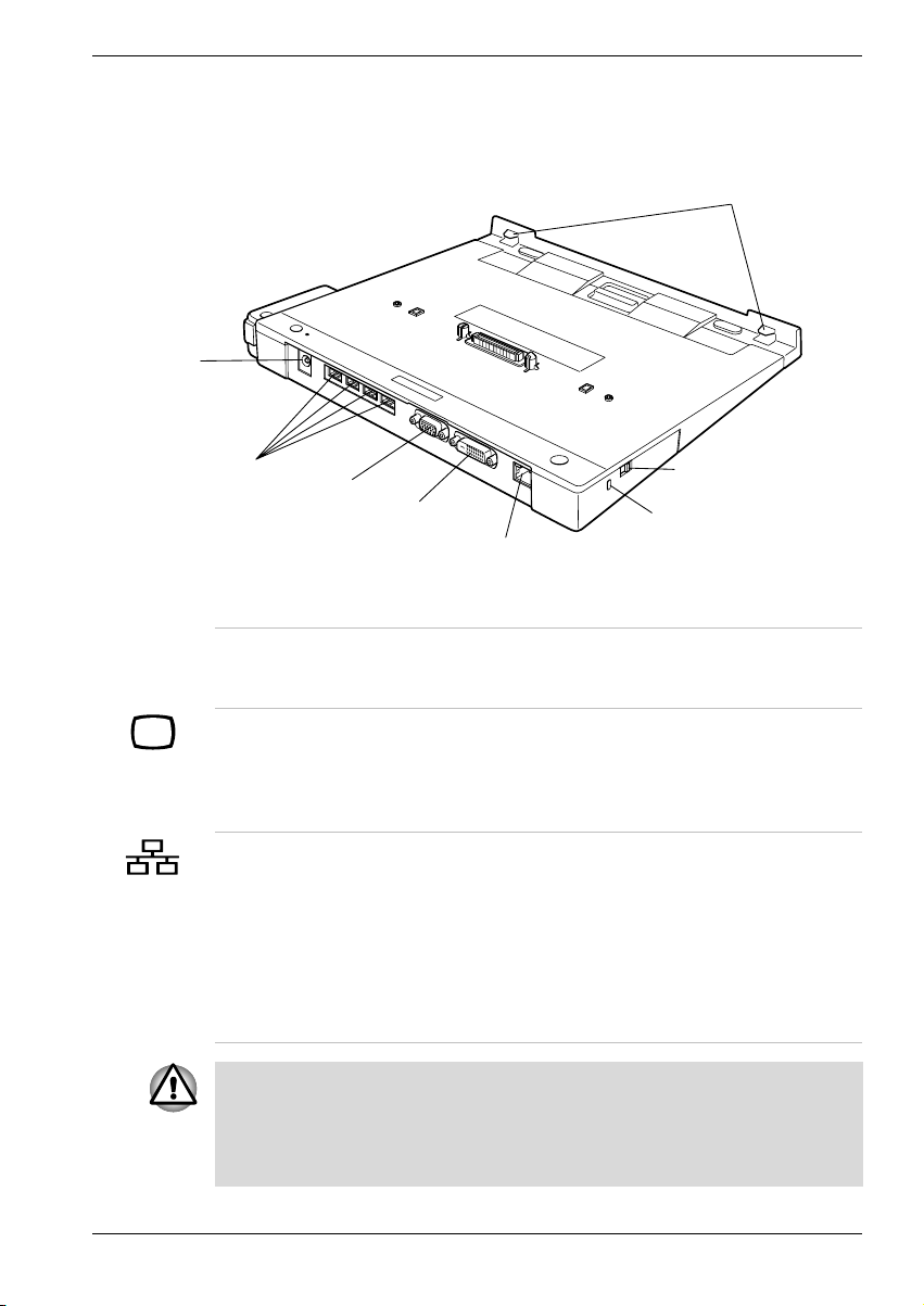
Rückseite
Abbildung 2-2 zeigt die Rückseite und die linke Seite des Port Replicators.
Gleichstro-
meingang
15 V
Rund um den Computer
Vordere Haken
USB-Anschluss
Anschluss für einen externen Monitor
DVI-Anschluss
Vordere Haken Die vorderen Haken passen in Löcher vorn am
Anschluss für
einen externen
Monitor
LAN-Buchse Über diese Buchse können Sie den Computer an
Wenn der Port Replicator an den Computer angeschlossen ist, verwenden
Sie nicht den Anschluss für einen externen Monitor die LAN-Buchse des
Computers. Wenn Sie diese Anschlüsse des Computers und des Port
Replicators gleichzeitig verwenden, können Sie den Computer oder den
Port Replicator beschädigen bzw. Daten verlieren.
Diebstahlsicherung
Schlitz für ein
LAN-Buchse
Abb. 2-2 Rückseite und rechte Seite
Sicherheitsschloss
Computer, um den sicheren Sitz des Port
Replicators zu gewährleisten.
An diesen 15-poligen Anschluss können Sie
einen externen Monitor anschließen. Die
Wiederaufnahmefunktion (bei Reaktivierung aus
Standby oder Ruhezustand) kann auch mit
einem externen Monitor verwendet werden.
ein LAN anschließen. Der Port Replicator
unterstützt Ethernet LAN (10 Mbit/s, 10BASE-T),
Fast Ethernet LAN (100 Mbit/s, 100BASE-Tx) und
Gigabit Ethernet LAN (1000 Mbit/s, 1000BASE-T).
Falls der Computer Gigabit Ethernet LAN
(1000BASE-T) nicht unterstützt, kann der Port
Replicator nur Ethernet LAN (10BASE-T) und Fast
Ethernet LAN (100BASE-Tx) unterstützen.
Benutzerhandbuch 2-3
Page 96

Rund um den Computer
Universal Serial
Bus (USB 2.0)Anschlüsse
DVI-Anschluss An diesen Anschluss können Sie einen DVI-
Je nach angeschlossenem Computermodell ist es unter Umständen
möglich, externe Monitore an den DVI-Anschluss und an den Anschluss für
einen externen Monitor anzuschließen und beide Monitore gleichzeitig als
Anzeigegeräte zu verwenden.
DC IN 15V
Gleichstromeingang
15 V
Linke Seite
In Abbildung 2-2 sind auch die Komponenten auf der linken Seite des Port
Replicators dargestellt.
Auf der Rückseite des Computers befinden sich
vier USB-Anschlüsse. Sie entsprechen dem
USB 2.0-Standard, unterstützen aber auch
USB 1.1. Die in den DMI-Informationen
angegebene Anzahl der USB-Anschlüsse kann
von der Anzahl der tatsächlich vorhandenen
Anschlüsse abweichen. In den DMI-Informationen
kann ein USB-Anschluss als zwei USBAnschlüsse angezeigt werden.
Monitor anschließen. Es wird nur der Typ DVI-D
unterstützt.
An diesen Anschluss wird der Netzadapter
angeschlossen.
Schlitz für ein
Sicherheitsschloss
Hier können Sie zum Schutz vor Diebstahl eine
Seilsicherung anbringen. Befestigen Sie ein Ende
der Sicherung am Port Replicator und das andere
an Ihrem Schreibtisch oder einem anderen großen
Gegenstand.
Computerschloss Diese Sicherung verhindert das Abtrennen des
Computers vom Port Replicator.
2-4 Benutzerhandbuch
Page 97

Netzadapter
Der Netzadapter kann sich automatisch auf eine beliebige Netzspannung
zwischen 100 und 240 Volt und auf eine beliebige Netzfrequenz zwischen
50 und 60 Hertz einstellen; dadurch kann der Port Replicator praktisch
überall auf der Welt eingesetzt werden.
Der Netzadapter wandelt Wechselstrom in Gleichstrom um und verringert
die an den Port Replicator gelieferte Spannung.
Rund um den Computer
Abb. 2-3 Netzadapter mit zwei Kontakten
Abb. 2-4 Netzadapter mit drei Kontakten
1. Der universelle Netzadapter und das Netzkabel im Lieferumfang des
Produkts variieren je nach Modell. Je nach Modell haben Sie einen
Stecker mit 2 oder 3 Kontakten erhalten.
2. Verwenden Sie keinen 3-zu-2-Kontaktadapter.
3. Das mitgelieferte Netzkabel entspricht den Sicherheitsvorschriften und
Bestimmungen in der Vertriebsregion, in der das Produkt gekauft
wurde, und sollte nicht außerhalb dieser Region verwendet werden.
Für die Verwendung in anderen Ländern/Gebieten erwerben Sie bitte
Netzkabel, die den jeweiligen Sicherheitsvorschriften und
Bestimmungen entsprechen.
Verwenden Sie nur den im Lieferumfang dieses Produkts enthaltenen
Netzadapter oder ein von Toshiba empfohlenes Alternativmodell, um die
Brandgefahr und Schäden am Gerät zu vermeiden. Bei Verwendung nicht
kompatibler Netzadapter kann es zu einem Brand oder zu einer sonstigen
Beschädigung des Produkts kommen.
Benutzerhandbuch 2-5
Page 98

Rund um den Computer
2-6 Benutzerhandbuch
Page 99

Anschlüsse
Der Port Replicator ist so konstruiert, dass sich mit wenigen Handgriffen
eine sichere Verbindung mit dem Computer herstellen lässt.
Das System unterstützt das Anschließen bzw. Trennen der DVD Docks bei
eingeschaltetem Computer (Warm Docking bzw. Warm Undocking).
Trennen Sie den Computer jedoch nicht vom Port Replicator, während eine
Anwendung ausgeführt wird.
Port Replicator anschließen
Wenn der Port Replicator an den Computer angeschlossen ist, verwenden
Sie nicht die Anschlüsse des Computers. Wenn Sie die Anschlüsse des
Computers und des Port Replicators gleichzeitig verwenden, können Sie
den Computer oder den Port Replicator beschädigen bzw. Daten verlieren.
Gehen Sie wie nachfolgend beschrieben vor, um den Port Replicator
anzuschließen.
1. Überprüfen Sie den Abstand zwischen der Vorderseite des Computers
und dem Anschluss des Port Replicators. Schieben Sie gegebenenfalls
den Feststeller nach vorn, so dass er direkt am Computer sitzt. Der
Computer befindet sich je nach Modell wie nachfolgend beschrieben in
Position zum Feststeller. Informationen zu zukünftigen Modellen finden
Sie im Internet unter www.Toshiba.com.
Feststellerposition von 1 bis 12
Kapitel 3
Position 1-12 Produktname
,
5
Benutzerhandbuch 3-1
,
PORTEGE M400
Page 100

Anschlüsse
Abb. 3-1 Feststeller verschieben
2. Trennen Sie alle Kabel von den Anschlüssen des Computers ab.
3. Schließen Sie die Kabel an die Anschlüsse des Port Replicators an.
4. Richten Sie vorderen Löcher am PC an den vorderen Haken des Port
Replicators aus, wenn Sie den PC auf den Port Replicator setzen.
Richten Sie den Haken des Computers und den Haken auf der linken Seite
des Port Replicators aus.
5. Drücken Sie den Computer vorsichtig nach unten, bis er hörbar
einrastet.
Abb. 3-2 Notebook an den Port Replicator anschließen
3-2 Benutzerhandbuch
 Loading...