

Page 1
~
~
~
~
~
~
~
(111111111
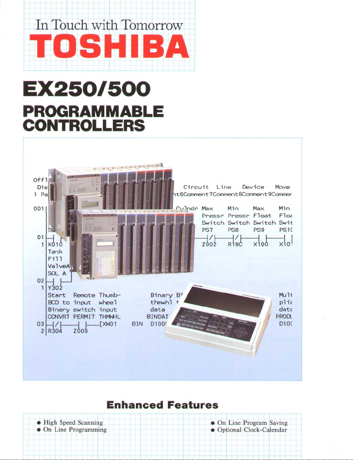
In Touch with Tomorrow
TOSHIBA
EX250/500
PROGRAMMABLE
CONTROLLERS
r-,,Indr Max Min
Pressr Pressr Float Flo
Switch Switch Switch Swit
PS7
Y30
Start Remote Thumb-
BCD to
Binary
~
R30 4~Z 0
input wheel
switch
CONVRT
PERMIT THMWHL
t_[Xw01
input
BIN D100
Binary B
thmwhl
data
BINDAT
;
t
(
PS8
Max
PS9
Min
.
PS1C
•
High Speed Scanning
•
On Line Programming
Enhanced Features
•
On Line Program Saving
•
Optional Clock-Calendar
Page 2
~
~
~
~
~
~
~
~
~
~
~
~
~
~
~
FEATURES
Fast Scan Time
The EX250/500 uses a 16 bit microprocessor and custom Toshiba integrated circuits to significantly reduce
program scan time
TWO CPU TYPES
The only difference between the EX250 and the EX500 is the CPU card
•
Application Memory
•
Execution Speed
•
Max Local I/O
Advanced Instruction Set
.
EX250 EX500
4K steps
1
.1 µs/contact
65 µs/16 bit addition
256 points 512 points
8K steps
0
.75 µs/contact
65 µs/16 bit addition
There are 15 basic relay ladder instructions and 64 special function block instructions
include instructions for performing
•
Arithmetic Operations
•
Register Logic
•
Min/Max/Avg
•
Function Generator
y points
.
.
: Given x, solve for f(x) where f(x) is interpolated based on a pre-entered
:
•
Data Manipulation
•
Comparisons
•
Step Sequencer
•
Trig
•
Upper/Lower Limit
•
Shift Register
.
The function blocks
. Functions
set of x,
Flexible Networking
EX250/500's are easily linked to
•
Higher Level Computers
:
•
•
Remote I/O Stations
Other EX250/500's
Easy Program Modification
Testing and modifying logic programs is simple
•
Real time power follow monitor
•
Instruction Search
•
On-line (in Run mode) program edit
. All controllers have
•
Forced I/O
•
Data Set
:
Intelligent 1/O Modules
Several intelligent, specialized I/O modules are available
•
ASCII/Basic Module
•
High Speed/Quadrature Input Module
:
4 Channel PID Control Module
•
•
Motion/Stepper Control Module
Clock Calendar
etc
The clock calendar function allows data gathering based on time, time scheduled operations,
kept by
•
Second
•
Day
:
Minute
•
•
Month
•
•
Hour
Year
. Time is
Page 3
~
~
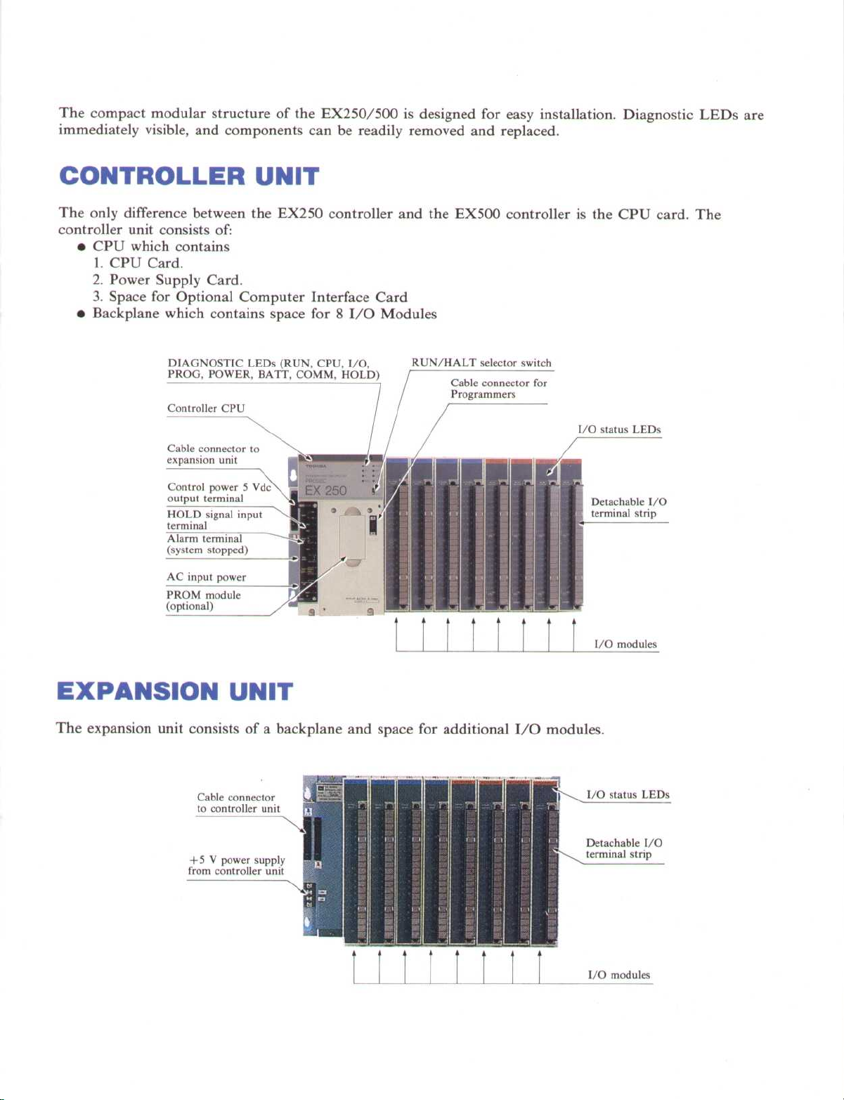
The compact modular structure of the EX250/500 is designed for easy installation
immediately visible, and components can be readily removed and replaced
.
. Diagnostic LEDs are
CONTROLLER UNIT
The only difference between the EX250 controller and the EX500 controller is the CPU card
controller unit consists of-
•
CPU which contains
1
. CPU Card
2
. Power Supply Card
3
. Space for Optional Computer Interface Card
•
Backplane which contains space for 8 I/O Modules
.
.
DIAGNOSTIC LEDs (RUN, CPU, I/O,
PROG, POWER, BATT, COMM, HOLD)
Controller CPU
Cable connector to
expansion unit
RUN/HALT selector switch
Cable connector for
Programmers
I/O status LEDs
. The
EXPANSION UNIT
The expansion unit consists of a backplane and space for additional I/O modules
Cable connector
to controller unit
+ 5 V power supply
from controller unit
.
Page 4
~
~
~
~
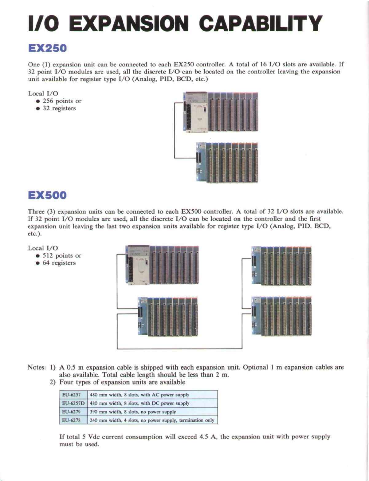
I/O EXPANSION CAPABILITY
EX250
One (1) expansion unit can be connected to each
32
point I/O modules are used, all the discrete I/O can be located on the controller leaving the expansion
unit available for register type I/O (Analog,
EX250
PID, BCD,
controller . A total of16I/O slots are available
etc
.)
. If
Local I/O
•
256
points or
•
32
registers
~ ~«iii<<<
EX500
Three
If32point I/O modules are used, all the discrete I/O can be located on the controller and the first
expansion unit leaving the last two expansion units available for register type
etc.).
(3)
expansion units can be connected to each
EX500
controller . A total of32I/O slots are available
.
I/O (Analog, PID, BCD,
Local I/O
•
512
points or
•
64
registers
Notes : 1) A
also available
2)
Four types of expansion units are available
EU-6257
EU-6257D
EU-6279
EU-6278
0
.5
m expansion cable is shipped with each expansion unit
. Total cable length should be less than
480
mm width,8slots, with AC power supply
480
mm width,8slots, withDCpower supply
390
mm width,8slots, no power supply
240
mm width,4slots, no power supply, termination only
2
. Optional 1 m expansion cables are
m
.
If total 5
must
be used
Vdc current consumption will exceed
4
.5
A, the expansion unit with power supply
.
Page 5
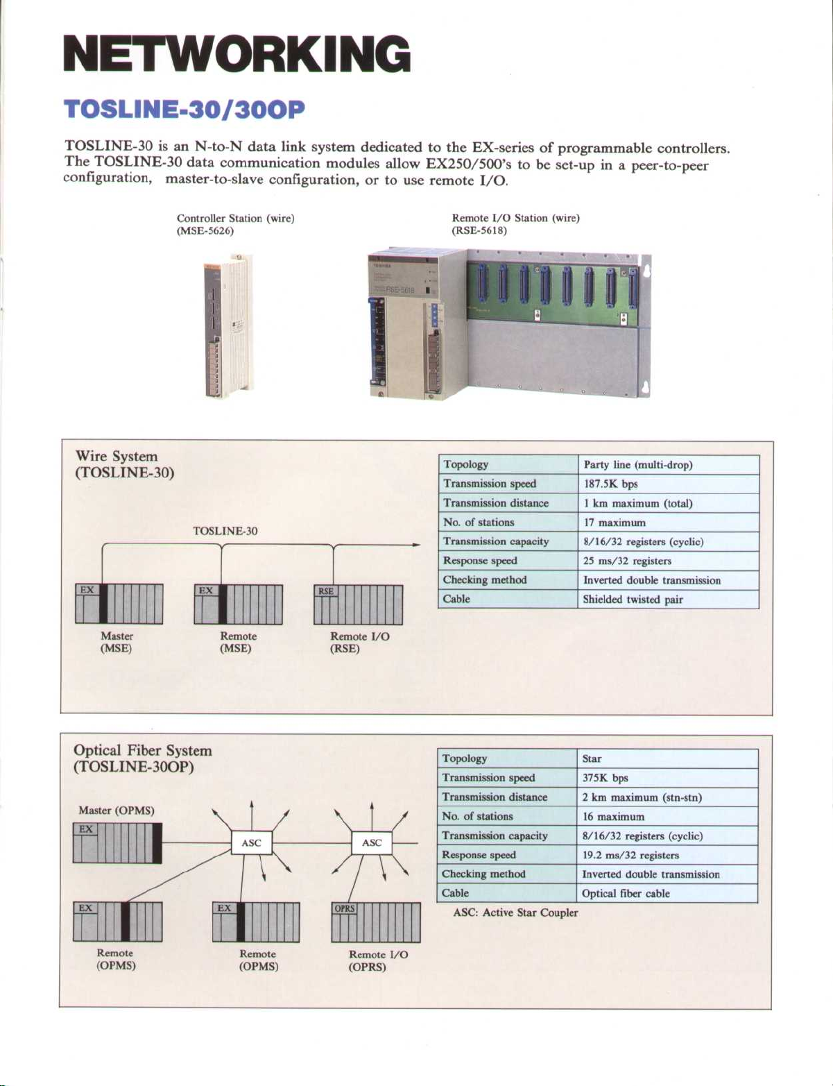
NETWORKING
TOSLINE-30/300P
TOSLINE-30 is an N-to-N data link system dedicated to the EX-series of programmable controllers
.
The TOSLINE-30 data communication modules allow EX250/500's to be set-up in a peer-to-peer
configuration, master-to-slave configuration, or to use remote I/O
Controller Station (wire)
(MSE-5626)
Wire System
(TOSLINE-30)
e
EX
I
~
Master
(MSE)
TOSLINE-30
EX
I
Remote
(MSE)
V
RSE
Remote I/O
(RSE)
Remote I/O Station (wire)
(RSE-5618)
Topology
Transmission speed
Transmission distance
No
. of stations
Transmission capacity
Response speed
Checking method
Cable
.
Party line (multi-drop)
187
.5K bps
1 km maximum (total)
17 maximum
8/16/32 registers (cyclic)
25 ms/32 registers
Inverted double transmission
Shielded twisted pair
Optical Fiber System
(TOSLINE-30OP)
Master (OPMS)
EX
S
EX
Remote
(OPMS)
Remote
(OPMS)
OPRS
Remote I/O
(OPRS)
Topology
Transmission speed
Transmission distance
No
. of stations
Transmission capacity
Response speed
Checking method
Cable
ASC
: Active Star Coupler
Star
375K bps
2 km maximum (stn-stn)
16 maximum
8/16/32 registers (cyclic)
19
.2 ms/32 registers
Inverted double transmission
Optical fiber cable
Page 6
i
11
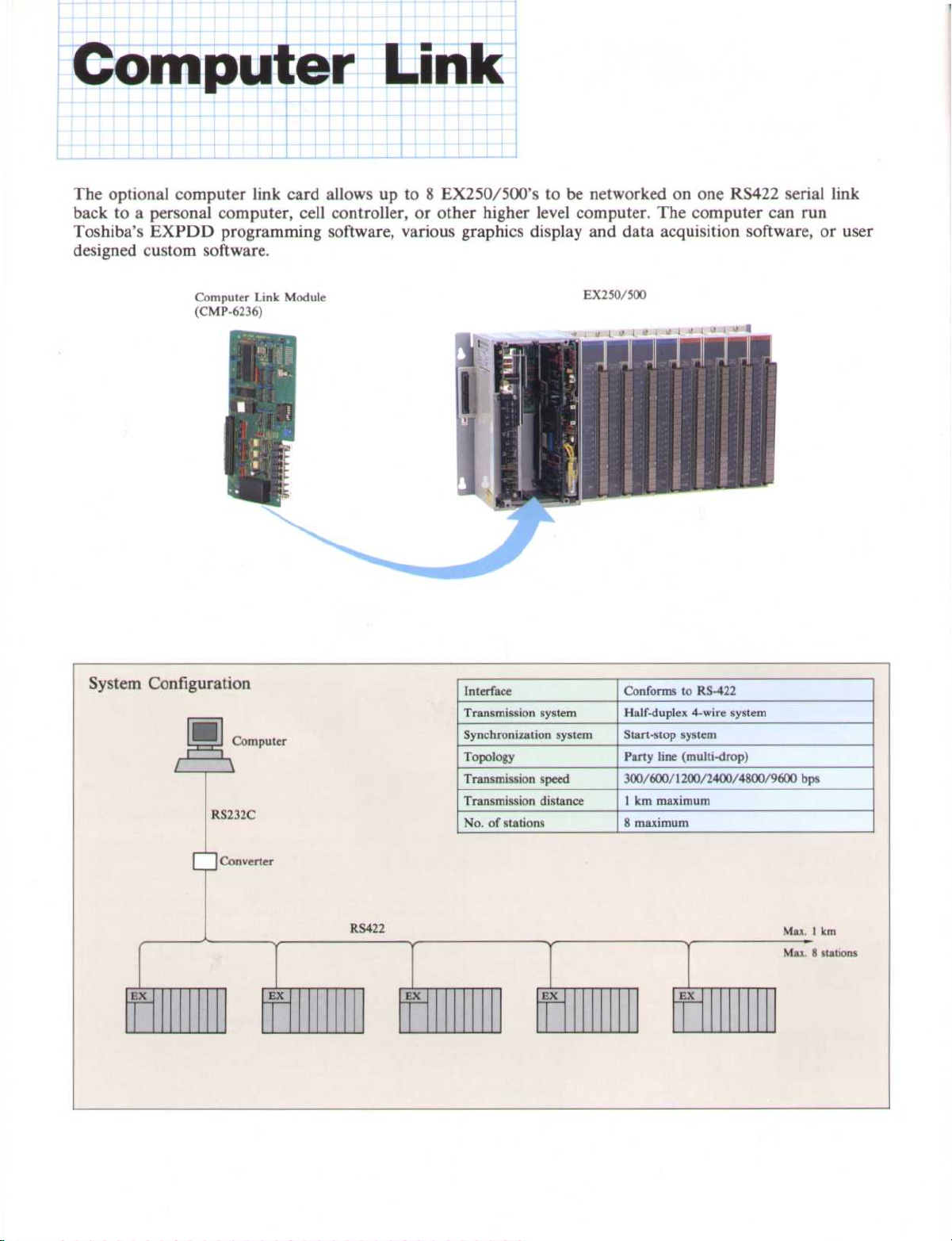
Computer Link
The optional computer link card allows up to 8 EX250/500's to be networked on one RS422 serial link
back to a personal computer, cell controller, or other higher level computer
Toshiba's EXPDD programming software, various graphics display and data acquisition software, or user
designed custom software
.
. The computer can run
Computer Link Module
(CMP-6236)
System Configuration
Computer
WE
RS232C
EX250/500
Interface
Transmission system
Synchronization system
Topology
Transmission speed
Transmission distance
No
. of stations
Conforms to RS-422
Half-duplex 4-wire system
Start-stop system
Party line (multi-drop)
300/600/1200/2400/4800/9600 bps
1 km maximum
8 maximum
EX
I Converter
I
EX
RS422
EX
EX
EX
Max
. 1 km
Max
. 8 stations
Page 7

~
~
~
~
PERIPHERALS
0"
"
EX-PDD
software
Floppy Disk
(3
.5",
2DD)
/
Floppy Disk Unit~(-
(FD 110)
Standard Printer
Cassette tape louder
(AP1/AP2)
(AP1/AP2)
I
> -
Graphic Programmer
(GPI10/110AP1/110AP2)
Handy Programmer
(HP100)
Mini Programmer
(M P 100)
D
Data Access Panel
(DP 100)
EX250/500
t
O
O
O
U
PROM Writer (PR100)
(for PROM Module)
PROM Module
There are two types of PROM Modules which can
be used with the EX250 and EX500 controllers
•
PROM6258 UV erasable PROM
. The
PROM6258 requires the PR100 PROM writer
for programming and a separate ultra violet
PROM eraser for clearing
•
PROM6260 Electrically erasable PROM
.
PROM6260 can be directly programmed and
erased by all Ver . 2, or later, EX250 and
EX500 controllers
.
.
. The
Page 8

~
~
~
~
~
~
~
~
~
Data Access Panel DP 100
The DP 100 is used primarily for viewing and
changing timers, counters and data register values
It does
logic
ASCII diagnostic messages and list their order of
occurrence
in dark areas
the face of the EX250 or EX500, or be connected
with a 2 meter cable
not allow
. The DP 100 can also display user defined
. The display is backlit for easy viewing
modification of the program
. The DP 100 can mount directly on
.
.
M///∎/UM/M/
Handy Programmer HP 100
The HP100 is hand-held graphic programmer
portability makes it ideal for maintenance use at
remote locations
of a full size programming terminal
•
Enter programs in ladder logic
•
On-line program monitor & edit (logic
intensifies to indicate power flow)
•
Block monitor for I/O and data registers
•
On-line data set & I/O force
•
Two display modes
-
-
TOSHIBA
. The HP 100 has all the features
Full
: 5 lines by 11 col
Zoom
: Full device description
.
. Its
.
Graphic Programmer GPI 10
The GP 110 has a large dot matrix LCD screen
that displays 7 lines by 11 columns
intensify to indicate power flow
vice address, current values in timers and counters,
and data register values are shown during program
execution
•
•
•
•
. The GP 110's advanced features include
Backlit screen
On-line programming
Stand alone programming (AP 1 & AP2)
Floppy disk drive interface (AP1& AP2)
0 NOON
N
so mom
mom
. Logic lines
. Device type, de-
:
∎∎///
∎∎∎∎∎
::
:::
:_
:::
∎
∎∎∎
Page 9

~
~
~
~
~
~
~
~
~
~
~
~
~
~
~
~
~
~
~
~
~
~
~
EX Program Development
& Documentation
Naturally it is possible to write and save EX250/500 programs on a personal computer
Development and Documentation software (EX-PDD) runs on any
computer and most IBM-PC compatibles such as Toshiba's laptop computers
•
Same EX-PDD Software supports EX 100,
EX250, EX500 and EX200B PLC's
•
Write Ladder/Function Block programs off-line
(PC disk) or on-line (EX250/500 memory)
•
Full-feature ladder editor includes move, copy,
insert, delete, search, etc
•
Make changes in EX250/500 program while in
run mode
•
Load and Save programs between PC disk and
EX250/500
•
Monitor power-flow status of on-line ladder
program and register values
•
\2111MI11111l1
Force I/O and coils on or off from keyboard
•
Document programs with commentary while
viewing ladder logic
•
Print ladder program with commentary and inladder coil cross reference
•
Print map options such as register values, in-
(EX-PDDTM)
.
The EX Program
IBM®-PC,
.
.
XT, AT, PS/2 personal
.
.
.
.
.
.
.
struction usage, device usage, forced devices, full
cross reference, etc
•
Built-in Modem initialize and Dial-up
.
.
.
Offline
Display Remove Remove
1 Page 2Synonym3Descrip4
001
01
~
02
03
File Name
Start Stop
Push
Push
Button Button Limit Limit Limit Limit Switch Switch Switch Switch ValveA
P81~P82~LS3~LS4~LS5~LS6~PS7~PSB~PS9~P510
1
Ix1d
1
._-I
2 RI
X01~2108
Tank
Fill
Va1veA
SOL A
Y101
Start Remote Thumb-
BCD to input wheel
Binary switch input
CoNVRT PERMIT THMWHL~BINDAT BINDAT~PRODUC NXTRNG
/I
~
~
Z 0
: EX-POD
Cyindr Cylndr Cylndr Cylndr Max~Min~Max~Min~Tank
Top~Bottom Left
X111~X267~RW
_[XW01
Page
5Comment6Camient7ComnentBCortment9Cormient0 Menu
Binary Binary
thmwhl thmwhl
data data
BIN
D1000]_[D1000 *
Circuit Line
Right Pressr Pressr Float Float Fill
2002~R19C
~
Device
X100~X101~Y302
00012~> >~D1001]-( )_
0
IBM
®
is a registered trademark of International Business Machines Inc
Move 1Ladder
Multi- Contiplied nued
data
SOL A
)
Remote
output
of
OVRFLW
( )-
2331
R000
Device
C omentary
Synonym
Reference
Address
.
Page 10

~
~
~
~
~
SPECIFICATIONS
Toshiba's many years of experience in semiconductor technology and solid-state electronics have resulted in
the production of versatile, highly efficient programmable controllers
General Specifications
.
Item
Power supply voltage
Power consumption
Allowable power interruption
Temperature
Operation
Storage
Humidity
Vibration
Shock
Noise immunity
Grounding
Atmosphere
Dust density
Power supply
Withstand voltage
Approx
. weight
Input/output
Cooling
100-120/200-240 Vac (+10/-15%)
Less than 50 VA (per power supply module)
Less than 10 ms for normal operation
0 - 55°C (32'-131°F)
-20 -
75°C (-4' -
20 - 90% RH, no condensation
16
.7 Hz, 3 mmp-p
10 G in X, Y, Z directions, respectively 3 times
1000 Vp-p 1 µs,
Less than 100 [I to ground
No corrosive gases
Less than 10 mg/m
1500 Vac for I min
1500 Vac for 1 min
4 kg (8
.8 lb)
~
8 -
10 kg (17.6-
2 kg (4
.4 lb)
~
Natural air-cooling
External Dimensions
EX250/500
50/60 Hz, 24 Vdc (+20/-15%)
-
167°F)
NEMA ICS3-304
3
.
. (digital I/O)
Basic unit
22 lb)~Basic unit w/ 8 I/O modules
Expansion unit w/o power supply
•
Basic unit
39
mm(1
5
161
(6
.3 in)
.5 in)
mm
Expansion unit w/o power supply
•
4-06
EX250
~
•
Expansion unit w/ power supply
....
I
~
.∎..
0..
MOMMOM
MISS
..
. .
. .
465 mm (18
480 mm (18
.3 in)
.9 in)
.-
.
rn
E
E
8
6
E
rv .
w
E
E
P
.5
.
Page 11

~
~
~
Functional Specifications
Item
Control method
Input/output control
Programming
t,
Program capacity
0
E
Memory type
Battery life
Processing speed
I/O registers
Number of instructions
Auxiliary relays/registers
Link relays/registers
N
u°Timers
Counters
Data registers
E
Special relays
.°,
Retentive registers
Clock-calendar (option)
Communications
Self diagnostics
CPU control input/output
CPU status indicators
Programming
R
C
a
..
Maintenance tool
Others
EX250
Stored program cyclic scan
Batch I/O (immediate I/O instruction is also available)
Ladder network with relay symbols and function blocks
4K steps
CMOS RAM (with battery backup)/EPROM/EPROM (ROMs are option)
Lithium battery
1 .1
.µs/relay contact
65 µs/16-bit addition
256 points contained in 16 registers 512 points contained in 32 registers
32 registers total (1 register = 16 points)
15 basic and 64 special functions
960 points contained in 60 registers (64 special relays contained 4 registers)
512 points contained in 32 registers
120 (0.1- 3276
96 (1-65535 counts)
1536 registers
Link status, Clock pulses, Alarm status, Self diagnostics, etc
Auxiliary relays/registers, timers, counters and data registers can be designated to maintain data upon
power failure
Year, month, day, hour, minute, second
Computer link (RS422)
PC link & remote I/O (TOSLINE-30)
CPU, RAM, ROM, I/O response, Watchdog timer, Power supply voltage, Battery voltage, Scan time, I/O
setting and Illegal instruction
RUN healty output
HOLD input
RUN:lit when running
CPU
:
lit when CPU is normal~BATT:lit when battery is normal
I/O
:~lit when I/O's are normal~COMM
PROG
: lit when program is normal
EX-PDD (software package for personal computer)
Graphic Programmer (GP110/GP110 AP1/110AP2)
Handy Programmer (HP100)
Mini Programmer (MP100)
Data Access Panel (DP100)
PROM Writer (PR100)-for use of UV-PROM module
5 years (25°C)
.7 sec), 8 (0
: dry contact input (24 Vdc
.01-327
: relay output (250 Vac/24 Vdc
.67 sec)
-
10 mA)
POWER
HOLD:lit when HOLD input is ON
8K steps
0
.75 µs/relay contact
65
.µs/16-bit addition
64 registers total (1 register = 16 points)
. (64 points total)
-
2 A)
: lit when power is normal
: flickers during communication
EX500
Page 12

~
~
~
~
~
~
~
~
~
~
~
~
~
~
~
~
~
~]~
~
~
~
~
~
~
~
~
~
~
~
~
~
~
~
~
~
~
~
~
~
~
~
~
~
~
~
~
~
~
PROGRAMMING
Toshiba's experience in industrial controls (robotics, process computers, etc
of programming instructions available on the EX250/500
timers, counters, etc . for standard relay ladder logic
functions, compare functions, trigonometric functions, math functions, etc
No.Instruction
I
NO CONTACT
2
NC CONTACT
3
COIL
4
FORCED
COIL
TRANSI-
TIONAL
5
CONTACT
TRANSI-
6
TIONAL
CONTACT
7
MCS
8
MCR
W
9 JCS
10
JCR
TON
I I
12
TOF
13
SS
14
CNT
END
15
W -. W
16
(FUN000)
17
K - W
(FUN00I)
TINZ
18
2
(FUN002)
c
c
,~
A
19
20
21
_
(FUN003)
W
y T
(FUN004)
(FUN005)
~O
~~
A
©H
T
i
-[MCS]--j
F-[MCS]-
-[JCS]-]
F-[JCR]-j
-[® TON ®]-
-[(D
-[® SS ®]-
-E
[-[END]-{
-[O
-[~
-[O
-[O
-[® W-
-[O
Symbol and Description
Normally open contactAI
Normally closed
contact
Relay coil
Coil is forced ON or
OFF
~
TOF ©]-
j
O 0
W -W
-W
O1-
KEW
TINZ [nn] ®]-~Table initialization
T-
T-
_
~]
. W [nn]
©-o©]-
.T [nn]
©-©]-
.T [nn] ®]-~Table-to-table transfer
Rising transitional
contact
Falling transitional
contact
Master control set
Master control reset
Jump control set
Jump control reset
ON delay timer
OFF delay timer
Single shot timer
Counter
End of program
transfer
Constant-to-register
transfer
Multiplexer
(table-to-register
transfer)
Demultiplexer
(register-to-table
transfer)
. There are 15 basic instructions, contacts, coils,
. There are also 64 special functions such as word logic
Step
.
Memory
2/3
2/3
2/3
2/3
3/4
of
I
1
I
I
I
I
I
1
1
1
3
4
5
5
4
No.Instruction
R + R
22
(FUN010)
.5
~ 23
c
°
C
°-
U
v
.a
Q
c
2
c
0
Z
9
a
°'
0u41
S
24
25
26
27
28
29
30
31
32
33
34
35
36
37
38
39
40
42
R - K
(FUN011)
R X R
(FUN012)
R / K
(FUN013)
R > R
(FUN014)
R = R
(FUN015)
R< R
(FUN016)
R ++ R
(FUN017)
R - - R
(FUN018)
R + K
(FUN020)
R - K
(FUN02I)
R X K
(FUN022)
R / K
(FUN023)
R > K
(FUN024)
R = K
(FUN025)
R < K
(FUN026)
AND
(FUN030)
OR
(FUN03I)
FOR
(FUN032)
NOT
(FUN034)
(F
RTR
-A [©
-[~
-[O
-A
-[0
-[O-
-
-[O ++
-[0
-10
-A [©
-
-[O /
-[O >' ~]
-[~'~]
-[~ <' ~]
-[0 AND @-@I-
-[
-[0 FOR
-
-[O RTR
.) has resulted in a very wide range
.
Symbol and Description
u
© ©
+
e
A -
[©
~]-
-'
~
X
~~©]
O ©
/ u~c ]-
_
_
> ~]
0]-
A
a
[~ < ©]
®
--
©-©]-
O O
[©
A
[©
~
[0 NOT ©e
©]-
+
. e~c
_
O O]_
e ~
o
O
©]-
X
. u
+ C
.
O-'©]-
_
_
OR
~register-to-register
@-©]-
]-
Addition
register + register
Subtraction
register
Multiplication
register X register
Division
register-register
Register comparison
greater than
Register comparison
equal to 3
Register comparison
less than
Addition double length
registers
Subtraction double
length registers
Addition
register + constant
Subtraction
register-constant
Multiplication
register X constant
Division
register = constant
Comparison register
greater than constant
Comparison register
equal to constant
Comparison register
less than constant
Logical AND
register-to-register
Logical OR
Logical EXCLUSIVE
OR register-to-register
Logical NOT
Rotate bits right
register
-
seep
Memory
4/5
4/5
4/5
4/5
3/4
3/4
3/4
or
4
4
4
3
3
4
1
4
4
4
3
4
Page 13

~
~
~
~
~
~
~
~
~
~
~
~
~
~
~
~
~
~
~
~
~
~
~
~
~
~
~
~
~
~
~
INSTRUCTIONS
u
S
e
o
2
A
U
y
.=
.a
.
No
Instruction
RTL
43
(FUN036)
AND
44
(FUN040)
OR
45
(FUN041)
FOR
46
(FUN042)
TEST
47
(FUN043)
48
(FUN0G46)
BIN
49
50
51
>
52
53
54
55
c
E
56
57
°
58
59
O50)
(FUN
BCD
(FUN051)
BDC2
(FUN052)
ENC
(FUN053)
DEC
(FUN054)
BITC
(FUN055)
UL
(FUN060)
LL
(FUN061)_-[~LL©~©]
MAX
(FUN062)
MIN
(FUN063)
AVE
(FUN064)
Symbol and Description
-[O
RTL
-[~
AND
OR
.
-[® EOR
-[O
-[Q NEG ©]-
-[O
-[® BCD1
-
-[O
-[Oq
-[O
-
-[~ MIN [nn]
-[® AVE [nn] ©]-
.
TEST ©]-
©]-
BIN
BCD2 ©]-
ENC ©]-
[0
DEC ®]-
BITC ©]-
UL
a MAX~@)1-
[~
.
0~©]
0
.©]-
©]-
[nn]
~]-
-
step"
of
Memory
Rotate bits left
Logical AND
register-to-constant
Logical OR
register-to-constant
Exclusive OR
register-to-register
Bit test
Two's complement
Convert BDC data in
to binary and store
0
in ©
Convert binary data in
to BDC and store
0
in ©
Convert double length
binary data starting in
to BDC and store
starting at
Encode contents of
register0and store in 3
register ®e
Decode contents of
register0and store in 3
register ®
All bits I in0are 71
counted and the total
is stored in ©
Compare value in ®
to UL in ®e.Turn on
output if
store limit in ©
Compare value in
to LL in ©e
output if(D< © and
store limit in ©
Take the maximum
value in the nn table
starting at0and
store in ©
Take the minimum
value in the nn table
starting at0and
store in ®
Take the AVE value
value man Table size
nn starting at 0 and
store in ©
0
0=0
Turn on
.
.
.
.
.
4
4/5
4/5
4/5
3/1
and
0
.
No.Instruction
60
c
9
61
o
,g
62
K
3
3
3
3
3
4
4
4
4
4
63
64
65
66
$
o
c
v
a
FG
(FUN065)
RT
FUN070
(
SIN
(FUN071)
ASIN
(FUN072)
COS
(FUN073)
ACOS
(FUN074)
SET
(FUN080)
RST
67
(FUN081)
DDSP
68
(FUN090)
DDSM
69
(FUN091)
70
72
73
74
75
76
IN
(FUN096)
OUT
(FUN097)
READ
(FUN098)
WRITE
(UN099)
STIZ
(FUNI00)
STIN -[0]-
(FUNI01)
STOT
(FUN102)
F/F
77
(FUN 110)
78
U/D
(FUN 1 11)
79
SR
(FUNI12)
-[® FG [nn]
-[~ RT ©]-
)
-[O
SIN
[
n ASIN a _
-
-[O
COS
O]-
-[O
ACOS ©]-
-[SET ~]-
[RST ~]-
-
-
[DDSP
0]-
-[DDSM
-[IN [nn] ®]-
-[OUT [nn] A]-
-[CH.® READ [nnn]
-[QWRITE[nnn]0-
-[STIZ [nn]
-[O]~
IR®
JDSRQ
SF/F
I
CU C/D
n
E
S (nn)
E
0
Symbol and Description
Function Generator
(given A, solve for
QA], where f[A] is interpolated based on a
pre-entered set of x, y
points)
.
Store f[A] in ©
Square root of 32-bit
data starting in
stored in ©
Sine of data in ® is
stored in ©
~]
©]-
O1-
Q
Arc sine of data ®
store in ©
Cosine of data in
stored in ®
Arc cosine of data in
is stored in ©
0
Device~is set continuously ON
Device
0
tinuously OFF
Diagnostic error code
is assigned to ®
Diagnostic error mes-
sage is assigned to ~
Immediate input
Immediate output
ASCII read
.CH
.©]- ASCII write
Step initialize for step
sequencer
Step input for step
sequences
Step output for step 2
sequencer
Filp-flop
Up/down counter
Shift register
Memory
is 3
.
.
.
is
0
.
.
.
is set con-
.
.
.
step
or
3
3
3
3
2
2
2
2/3
3/4
.
3
3
5
5
3
2
2
2
3
Page 14

1/O MODULES
Digital Input
Item
Input voltage
Min
. ON voltage
Max
. OFF voltage
Input current
Input points
ON delay
OFF delay
Consumed current
Weight
DI-6261
16 pts (8 pts common)
Less than 10 ms
Less than 15 ms
Less than 50 mA (5 V)
470 g
DI-6271
30 Vdc
10
-
9
.6 V
4
.8 V
10 mA (24 Vdc)
32 pts (16 pts common)
Less than 80 mA (5 V)
550 g
DI-6271H
Less than 1
Less than 1
.0 ms
.5 ms
DI-6249
8
.5 V
4
.0 V
64 (dynamic scan)
Less than 1
Less than 1
Less than 100 mA (5 V)
.7 ms
.7 ms
500 g
Item
Input voltage
Min
. ON voltage
. OFF voltage
Max
Input current
Input points
ON delay
OFF delay
Consumed current
Weight
INP-6262
85-132 Vac
75 V
25 V
14 mA (100 Vac)
Less than 70 mA (5 V)
Digital Output
Item
Output voltage
Load current
Output point
ON delay
OFF delay
Leakage current
Consumed current
Weight
DO-6263
2 A/pnt, 5 A/common
16 pts (8 pts common)
100 µA
Less than 140 mA (5 V)
550 g 700 g
INP-6272 INP-6266
170-250 Vac
14 mA (200 Vac)
16 points
Less than 15 ms
Less than 15 ms
510 g
DO-6273
10
- 30 Vdc
.5 A/pnt, 5 A/common
0
32 pts (16 pts common)
Less than I ms
Less than I ms
Less than 200 mA (5 V)
150 V
50 V
10 µA
132 Vac
85
75 V 150 V
25 V
10 mA (100 Vac)
32 points
Less than 25 ms
Less than 20 ms
Less than 100 mA (5 V)
550 g
RO-6265
250 Vac/30 Vdc (max)
2 A/pnt, 8 A/common
16 pts (8 pts common)
Less than 10 ms
Less than 15 ms
Non
Less than 80 mA (5 V)
650 g
INP-6276
170-250 Vac
50 V
10 mA (200 Vac)
RO-6275
2 A/pnt, 16 A (total)
16 pts (independent)
Item
Output voltage
Load current
Output points
ON delay
OFF delay
Leakage current
Consumed current
Weight
ACO-6264
85-132 Vac
2 A/pnt, 5 A/common
16 pts (8 pts common)
Less than 2 ms
Less than 12 ms
I mA (100 V/50 Hz)
Less than 230 mA (5 V)
Less than 400 mA (5 V)
550 g
ACO-6274
170-250 Vac
2 mA (200 V/50 Hz)
ACO-6269
-
250 Vac (+ 10/-15%)
24
.5 A/pnt, 3
0
.2 A/common, 5 A (total)
32 pts (16 pts common)
Less than I ms
Less than 1/2 cycle
I mA (100 V/50 Hz)
Less than 800 mA
800 g
Page 15

Analog Input
Item
Input range 0 Input impedance
Input channels
Conversion speed
Resolution
Data format
Accuracy
Consumed current
AI-6290B10
±10 V
1 Mil or more
Analog Output
Item
Output range
Load impedance
Output channels
Conversion speed
Resolution
Data format
Accuracy
Consumed current
AO-6295B10
0 -
_L10 V
More than 500 ft
AI-6290B5
0 - ±5 V
2 channels (isolated)
32 ms/2 channels
±2000 (2's complement)
±0
Less than 250 mA (5 V)
AO-6295B5
0 - ±5 V
More than 250 ft
±2000
(2's complement)
Less than 300 ft
Less than I ms
±0
Less than 100 mA
AI-6290B20
0 -
±20 mA
250 ft
1/4000 (FS)
.2% (FS, 25°C)
AO-6295B20
0 -
±20 mA
2 channels
1/4000 (FS)
.2% (FS, 25°C)
AI-6292V AI-6292C
0 -
±10 V/1
1 Mft or more
±2000 (±10 V), 0-4000 (1-5 V/4-20 mA)
AO-6295U5
More than 250 ft
- 5 V
8 channels
2 ms/8 channels
I -
5 V
0-4000
4 -
20 mA
250 ft
AO-6295U20
4 -
20 mA
Less than 550 ft
RTD Input
Item
RTD type
Measuring method
Temperature range
Resolution
Resistance adjustment
Input channels 4 channels
Load current
Data format
Accuracy
Consumed current Less than 340 mA
RTD-6240P
Ptl00
Three-wire/two-wire system
-180 -
+ 200'C
0
.1 °C/count
Within 2 ft Within 3 ft
2 mA
±2000 (2's complement)
±0
RTD-6240N
-50 -
.5% (FS)
Ni500
0
.3 mA
+200°C
Thermocouple Input
Input range
Input impedance
Input channels
Conversion speed
Resolution
Data format
Accuracy
Consumed current
High-speed Pulse Counter
Item
Counting speed
Input voltage
Input channels
Count value range
Comparison output
2 points (immediate output)
PI-6246A
50 kpps (max)
5/12 Vdc
I channel (phase A, B, M)
0 -
65535
Functions
Consumed current
Others
Item
Item
TC-6294
±12
.5/±25/±50/±100 mV
1 Mft or more
8 channels
140 ms/8 channels
1/4000 (FS)
±2000 (2's complement)
±0
.4% (FS)
Less than 250 mA (5 V)
PI-6246A
1
. Quadrature counter
2. Up/down counter
3
. Speed counter
Less than 500 mA (5 V)
Built-in 12 Vdc
- 0
.2 A (max)
Page 16

INTELLIGENT I/0 MODULES
PID Control Module
Item
No
. of loops
Sampling time
7
Signal range
a
Resolution
Signal range
,
p
Resolution
Proportional
a
Integral
c
Derivative
Auto-tuning
Consumed current
PID-6730V PID-6730C
4 loops
0.1-
120
.0 sec
4 -
1- 5 V
1/8192
I -
5 V
1/4096
0
.1 -
1000
0
.1 -
6553
6553
0 -
Step Response Method
Less than 800 mA (5 V)
.5 sec
20 mA
4 - 20 mA
.1%
.5 sec
ASCII/BASIC Module
Item
Language
Program memory
Function
External interface
Baud rate
Consumed current
ASC-6210
BASIC-52 (interpreter)
32K bytes (EEPROM) 64K bytes (EEPROM)
1
. Communication with ASCII devices
2
. BASIC co-processor
RS232C (2 ports)
CH 1
: input/output
CH 2
: output only
: 110/300/600/1200/2400/4800/9600
CH 1
/19200 bps
: Set by BAUD statement of BASIC
CH 2
800 mA (5 V)
ASC-6210A
Motion Control Module
Item
. of axis
No
Speed (pulse rate)
Positionning range
Positionning system
Point data capacity
Basic parameters
Parameter setting
Consumed current
Acceleration/deceleration
Backlash compensation
Zero position compensation
Dwell time
By EX CPU or programmer (GP, HP, MP)
600 mA (5 V) -
MC-6243
I axis
Max
. 200 kpps
± 1000000 pulses
Absolute/increment
511 points
: 0-27 sec
: 0-1000 pulses
: ± 10000 pulses
: 0
.00
- 655
.00 sec
w/o programmer
Driver
\J
Page 17

Specifications of Peripheral Devices
Item
Power supply voltage
Power consumption Less than 20 VA
Operating temperature 0 Storage temperature
Humidity
Approx
. weight
Display
Keyboard
Connection to PC
Programming
Program display
Program edit
Stand-alone programming
On-line status monitor
o
U
C
Data setting
Debugging
Documentation
PC control
PC status monitor
Supported PC types
Supported devices
Device
Size
Type
No
. of keys
Method
Cable length
GPI10AP2 GPI10API
100
-
240 Vac (+ 10/- 15%) -
3 kg (6
.6 Ib)
LCD with back light
480 X 128 dot
63 42
5 m (16
.5 ft) (standard), max
Ladder network with relay symbols and function blocks
I1 columuns X 7 lines
Element add/delete/replace, Columun insert/delete, Line insert/delete, Page
add/replace/insert/delete
Available
Program real time power flow monitor, Data monitor
(block monitor)
Modification of register/device data (on-line/off-line)
Input/output disable, Forced coil, Data setting, Search
Program, Cross-reference,
Device/register usage map
Operation status (RUN/HALT/ERROR), Error messages
EX 100,
EX200B
'
EX250, EX500,
EX2000
Floppy Disk Unit (FD 110),
Printer, Cassette tape loader
GPIIO
50/60 Hz
-20 -
Membrane keyboard
Serial transmission (current loop)
. 100 m (330 ft)
No No No No
No No
RUN/HALT/RUN-F
EX100, EX200B, EX250, EX500
Cassette tape
loader
HP100
0
.2 A
40°C (32-104°F)
75°C
(-48 -
167°F)
20 -
90% RH
LCD
120 X 64 dot
with software beeper
I1 columuns
X 5 lines
No
MP100
5 Vdc (supplied from PC)
0
.3 A
0
.4 kg (
.88 lb)
LCD with back light
16 characters X 2 lines
48
2 m (6
.6 ft)
1 element
Element
ON/OFF,
Data monitor
No
Cassette tape
loader
DP100
0
.4 A
24
No
No
No
Data monitor
No
No
No
EX 100,
EX200B,
EX250, EX500,
EX2000
No
Page 18

ORDERING INFORMATION
...
...
...
MEMO
SOONER
......
......
...
.H
Item
Description
Controllers and Expansion Units
Contains CPU, Base, AC PS
EX250 Basic Unit
Contains CPU, Base, DC PS
Contains CPU, Base, AC PS
EX500 Basic Unit
Contains CPU, Base, DC PS
480 mm width, 8 slots, AC PS (EU-6257)
Expansion Unit
(0
.5 m expansion cable attached)
480 mm width, 8 slots, DC PS (EU-6257D)
390 mm width, 8 slots, w/o PS (EU-6279)
240 mm width, 4 slots, w/o PS (EU-6278)
Controller Options
PROM Module
Computer Link Module
RS232C Adapter
EEPROM type
EPROM (UV-PROM) type
RS422 multi-drop link
RS422/RS232C converter for computer link
RS485/RS232C converter for computer link
Standard
w/ clock-calendar
Standard
w/ clock-calendar
Standard
w/ clock-calendar
Standard
w/ clock-calendar
Part number
EX25 * 1 A
EX25*2A
EX25* 1 D
EX25*2D
EX50* 1 A
EX5O*2A
EX50* 1 D
EX5O*2D
EX25UEU*6257
EX25UEU*6257D
EX25UEU*6279
EX25UEU*6278
EX25PROM6260
EX25PROM6258
EX25PCMP6236
EX25PADP6237A
EX25PADP6237B
I/O Modules
DC Input Module
AC Input Module
DC Output Module
AC Output Module
Relay Output Module
16 points, 12
32 points, 12 32 points, 12 - 24 Vdc, quick response
64 points (dynamic scan), 12
16 points, 100-120 Vac
16 points, 200
32 points, 100 32 points, 200 - 240 Vac
16 points, 12-24 Vdc, 2 A/point (max)
32 points, 12 -
16 points, 100-120 Vac, 2 A/point (max)
16 points, 200-240 Vac, 2 A/point (max)
32 points, 24
16 points, 250 Vac/30 Vdc (max), 2 A (max)
16 points independent
- 24 Vdc
24 Vdc
- 240 Vac
120 Vac
24 Vdc, 0
-
240 Vac, 0
,
- 24 Vdc
.5 A/point (max)
.5 A/point (max)
250 Vac/30 Vdc, 2 A
EX25MDI*6261
EX25MDI*6271
EX25MDI*6271H
EX25MDI*6249
EX25MINP6262
EX25MINP6272
EX25MINP6266
EX25MINP6276
EX25MDO*6263
EX25MDO*6273
EX25MAC06264
EX25MAC06274
EX25MAC06269
EX25MRO*6265
EX25MRO*6275
Page 19

Item
I/O Modules (cont'd)
Description
Part number
2 channels
Analog Input Module
8 channels
Analog Output Module
RTD Input Module
Thermocouple Input
High-speed Pulse Counter
PID Control Module
ASCII/BASIC Module
Motion Control Module
2 channels
4 channels
8 channels, ±12
I channel (phase A, B, M), 50 kpps (max)
4 loops
2 parts of RS232C, BASIC-52
I axis, 200 kpps (max)
.5/±25/±50/±100 mV
TOSLINE-30 Stations
±10 V
±5 V
±20 mA
±10 V/1-5 V
4 -
20 mA
±10 V
±5 V
±20 mA
I -
5 V
4 -
20 mA
Pt 100
Ni500
I -
5 V
4 -
20 mA
32K bytes
64K bytes
EX25MAI*6290B10
EX25MAI*6290B5
EX25MAI*6290B20
EX25MAI*6292V
EX25MAI*6292C
EX25MAO*6295B10
EX25MAO*6295B5
EX25MAO*6295B20
EX25MAO*6295U5
EX25MAO*6295U20
EX25MRTD6240P
EX25MRTD624ON
EX25MTC*6294
EX25MPI*6246A
EX25MPID6730V
EX25MPID6730C
EX25MASC6210
EX25MASC6210A
EX25MMC*6243
TOSLINE-30 (wire)
TOSLINE-300P (optional)
Controller station
Remote I/O station
Controller station
Remote I/O station
Active Star Coupler
Peripherals
Graphic Programmer
(5 m cable attached)
Handy Programmer
Mini Programmer
Data Access Panel
Floppy Disk Unit
PROM Writer
Note
: UL listed types are also available
Standard
Stand-alone, Documentation
For EX2000
2 m cable attached
2 m cable attached
2 m cable attached
3
.5 inch, I drive
For ROM-6258 PR100
.
100-120 Vac PS
200-240 Vac PS
GP 110
GP110AP1
GP110AP2
HP100
MP100
DP100
FDIIO
EX25MMSE5626
EX25M8
EX25MOPM56OPM5611
EX25MOPR5612
TL3CUASC5617A1
TL3CUASC5617C1
EX25UGP* 110
EX25UGP*110*API
EX25UGP*110*AP2
EX25UHP*100
EX25UMP*100
EX25UDP*100
EX25UFD*110
EX25UPR*100
Page 20

TOSHIBA
TOSHIBA INTERNATIONAL (EUROPE)
1 Roundwood Avenue
Stockley Park, Uxbridge
Middlesex UB11 1AR, UNITED KINGDOM
Tel
: 081 848 4466
E_mail n
igels@toshibai
Fax
: 081 848 4969
.co.uk
LTD
TOSHIBA INTERNATIONAL CORPORATION
Industrial Equipment Division
13131 West Little York Road
Houston, TX
Tel
: 713-466-0277
E_mail
. 77041~U.S.A
: plc@tic
.toshiba
.
Fax
: 713-466-8773
.co
m
TOSHIBA do BRASIL, S.A.
Estrade dos Alvarengas 5500
Sao Bernardo do Campo
Sao Paulo 0985-5500, Brazil
Tel
: 55-11-7689-7199
Fax
: 55-11-7689-7189
a
ntoneli@tbb
.toshiba
.com
.b
r
.
TOSHIBA INTERNATIONAL
CORPORATION
Unit 1, 9 Orion Road Lane Cove
N.S.W
. 2066, AUSTRALIA
Tel
: 02-428-2077 Telex
E_mail
: preston@toshiba
PTY
. LTD
: AA25192
.co .a
.
u
TOSHIBA CORPORATION
Industrial Equipment Department
1-1, Shibaura 1-chome, Minato-ku
Tokyo 105, JAPAN
Tel
: 03-3457-4900 Cable
E_mail
: osamu
.seki@toshiba
Toshiba Asia Pacific PTE
200 Cantonment Rd
Southpoint, 089763 Singapore
Ph
: 65-324-1048
Fax
: 65-324-5286
. #12-01
: Toshiba Tokyo
.co.jp
. LTD
 Loading...