


E6581741h
TOSVERT VF-MB1/S15
EtherNet/IP™ - Modbus® TCP option
Function Manual
IPE002Z
NOTICE
1. Read this manual before installing or operating. Keep this instruction manual on hand
of the end user, and make use of this manual in maintenance and inspection.
2. All information contained in this manual will be changed without notice. Please
contact your Toshiba distributor to confirm the latest information.

E6581741
- 1 -
- 1 -
Introduction
Thank you for purchasing the “EtherNet/IP™ - Modbus® TCP option (IPE002Z)” for
TOSVERT VF-MB1/S15 inverter. Before using EtherNet/IP™ - Modbus
®
TCP module,
carefully read this function manual in order to completely and correctly utilize its excellent
performance.
This option needs the option adaptor to connect VF-S15 which type form is SBP009Z.
Please match here and buy it when SBP009Z is not at hand yet.
After reading this function manual, please keep it handy for future reference.
For details of its general handling, see an instruction manual attached with the option
unit.
- TOSVERT VF-MB1 Instruction Manual ························································· E6581697
- TOSVERT VF-S15 Instruction Manual ·························································· E6581611
- TOSVERT VF-MB1/S15 communication option Precautions Manual···········E6581739
- TOSVERT VF-MB1 Communication Function Instruction Manual················ E6581726
- TOSVERT VF-S15 Communication Function Instruction Manual················· E6581913
EtherNet/IP™ is a trademark of ControlNet International, Ltd.
Modbus
®
TCP is a registered trademark of AEG Schneider Automation International S.A.S.
Handling in general
Warning
Prohibited
Do not connect or disconnect a network cable while the Inverter power is on.
It may lead to electric shocks or fire.
Mandatory
See the instruction manual attached with the option unit for cautions the handling.
Otherwise, it may lead to electric shocks, fire, injuries or damage to product.
Network control
Warning
Prohibited
Do not send the value out of the valid range to objects and attributes.
Otherwise, the motor may suddenly start/stop and that may result in injuries.
Mandatory
Use an additional safety device with your system to prevent a serious accident due to the
network malfunctions. Usage without an additional safety device may cause an accident.
Caution
Mandatory
Set up “Communication error trip function (see below)” to stop the Inverter when the
option unit is deactivated by an unusual event such as tripping, an operating error,
power outage, failure, etc.
- Network Time-Out, Inverter operation at disconnection, Preset speed operation
selection
(Refer to " 3.2.3 Network error detection (c100 - c103, c523)" for details)
Deactivated the option module may cause an accident, if the “Communication error trip
function” is not properly set up.
Make sure that the operation signals are STOP before resetting Inverter’s fault. The
motor may suddenly start and that may result in injuries.
Notes on operation
Notes
When the control power is shut off by the instantaneous power failure, communication
will be unavailable for a while.
The Life of EEPROM is approximately 100,000 times. Avoid writing a command more
than 100,000 times to the same parameter of the Inverter and the option module.

E6581741
- 2 -
Table of Contents
1. OVERVIEW.................................................................................................................................................4
2. NAMES AND FUNCTIONS ........................................................................................................................4
2.1. Outline ..................................................................................................................................................4
2.2. RJ45 connector pin layout ...................................................................................................................5
2.3. Example of connection to an EtherNet/IP™ and Modbus® TCP .........................................................5
2.4. LED indicator........................................................................................................................................6
3. PARAMETERS ...........................................................................................................................................7
3.1. Communication parameters.................................................................................................................7
3.2. The details of the parameter setting ..................................................................................................11
3.2.1. Device name (c081-c096).................................................................................................11
3.2.2. Assigning IP addresses (c504, c505-c516) ...............................................................12
3.2.3. Network error detection (c100 - c103, c523) ...............................................................13
3.2.4. Command data (c001-c006), Monitor data (c021-c026).........................................14
4. OBJECTS..................................................................................................................................................22
4.1. Identity Object (0x01) .........................................................................................................................23
4.2. Message Router Object (0x02) ..........................................................................................................25
4.3. Assembly Object (0x04) .....................................................................................................................26
4.4. Connection Manager Object (0x06) ...................................................................................................27
4.5. Motor Data Object (0x28)...................................................................................................................28
4.6. Control Supervisor Object (0x29).......................................................................................................29
4.6.1. Run/Stop Event Matrix ................................................................................................................31
4.6.2. State of the drive.........................................................................................................................31
4.6.3. Control Supervisor State Transition Diagram .............................................................................31
4.7. AC/DC Drive Object (0x2A) ...............................................................................................................32
4.8. Parameter Objects (0x64)..................................................................................................................33
4.9. Parameter Objects (0x65)..................................................................................................................35
4.10. Port Object (0xF4) ..........................................................................................................................36
4.11. TCP/IP interface Object (0xF5) ......................................................................................................37
4.12. Ethernet link object (0xF6) .............................................................................................................40
5. CONFIGURATION OF THE ASSEMBLIES.............................................................................................44
5.1. List of Assembly Object Instance .......................................................................................................44
5.1.1. Instance 20: CIP basic speed control output ..............................................................................45
5.1.2. Instance 70: CIP basic speed control input ................................................................................45
5.1.3. Instance 21: CIP extended speed control output........................................................................46
5.1.4. Instance 71: CIP extended speed control input..........................................................................46
5.1.5. Instance 100: Native drive output ...............................................................................................47
5.1.6. Instance 150: Native drive input .................................................................................................47
5.1.7. Instance 101: Native drive output ...............................................................................................49
5.1.8. Instance 151: Native drive input .................................................................................................49
5.1.9. Instance 102: Native drive output ...............................................................................................51
5.1.10. Instance 152: Native drive input..............................................................................................51
5.1.11. Instance 105: TOSHIBA specific output..................................................................................52
5.1.12. Instance 155: TOSHIBA specific input....................................................................................52
6. ABOUT EDS FILE ....................................................................................................................................54
7. INTEGRATION IN RSLOGIX™................................................................................................................54
7.1. Create a new project ..........................................................................................................................54
7.2. Add a EtherNet/IP scanner to the I/O configuration...........................................................................55
7.3. Configure the VF-MB1/S15 EtherNet/IP module ...............................................................................57
7.4. Download the program to the PLC.....................................................................................................59
7.5. Edit the I/O scan data.........................................................................................................................61
8. MODBUS TCP SERVER ..........................................................................................................................64
8.1. Modbus TCP frames ..........................................................................................................................64
8.2. Drive Modbus servers ........................................................................................................................64
8.3. List of Modbus functions supported ...................................................................................................64
8.4. "03 (0x03) Read Holding Registers" function ....................................................................................65
8.5. "06 (0x06) Write Single Register" function.........................................................................................66
8.6. "16 (0x10) Write Multiple Registers" function ....................................................................................67

E6581741
- 3 -
8.7.
"23 (0x17) Read/Write Multiple Registers" function...........................................................................68
8.8. "43 (0x2B) Read Device identification" function ................................................................................69
8.9. Parameter data ..................................................................................................................................71
9. IO SCANNING SERVICE..........................................................................................................................72
9.1. Presentation .......................................................................................................................................72
9.2. Periodic variables...............................................................................................................................72
10. EXAMPLE OF THE SETUP WITH PL7™.............................................................................................73
10.1. Defining the hardware configuration...............................................................................................73
10.2. BOOTP configuration .....................................................................................................................74
10.3. Configuring Modbus messaging.....................................................................................................75
10.4. Configuring periodic variables ........................................................................................................76
11. COMMAND & SETPOINT SELECTION (LOCAL/REMOTE)...............................................................77
12. UNUSUAL DIAGNOSIS........................................................................................................................79
12.1. Option error ....................................................................................................................................79
12.2. Disconnection error of network cable.............................................................................................79
13. WEBSERVER........................................................................................................................................80
13.1. Access to the webserver ................................................................................................................80
13.2. Web pages structure ......................................................................................................................81
13.3. Drive monitor (Main menu: Monitoring) ..........................................................................................82
13.4. Drive parameters (Main menu: Monitoring)....................................................................................83
13.5. Network parameters (Main menu: Network Setup)........................................................................85
13.6. Modbus scanner (Main menu: Network Setup)..............................................................................85
13.7. EthIP scanner (Main menu: Network Setup)..................................................................................86
13.8. Administration (Main menu: Network Setup)..................................................................................87
13.9. TCP/IP statistics (Main menu: Diagnostics) ...................................................................................88

E6581741
- 4 -
1. Overview
The EtherNet/IP™ - Modbus® TCP option (IPE002Z) allows the VF-MB1/S15 inverter to be connected
into the EtherNet/IP™ - Modbus
®
TCP network.
2. Names and functions
The drawing below shows names and functions of main parts.
2.1. Outline
Shielded female RJ45
EtherNet/IP Connector
(Port L)
LED indicator (See 2.4)
Shielded female RJ45
EtherNet/IP Connector
(Port R)
Connector to the inverter
Release tab
MAC address Label
(Back side)
NS
LNK
MS
LNK

E6581741
- 5 -
2.2. RJ45 connector pin layout
The EtherNet/IP™ - Modbus® TCP option is equipped with two shielded RJ45
connectors.
When you use VF-MB1, the shielding is connected to the drive ground. When you use
VF-S15, the shielding is connected to the grounding terminal of option adapter.
Use an STP (shielded twisted pair) Ethernet cable.
The transmission speed is detected automatically by the unit (10 Mbps or 100 Mbps).
The card can operate in half duplex or full duplex mode, whether connected to a hub or a
switch and regardless of the transmission speed (10 Mbps or 100 Mbps).
Pin Signal
1 TD+
2 TD-
3 RD+
4 -
5 -
6 RD-
7 -
8 -
* Fix a cable so that a communication connector may be not taken the weight of wire.
2.3. Example of connection to an EtherNet/IP™ and Modbus® TCP
Example of daisy chain topology and star topology
Daisy chain topology Star topology
8………………1
Port L and Port R
Ethernet switch
PLC

E6581741
- 6 -
2.4. LED indicator
The LED shows the present
status of the network and module.
The behavior of LNK LED
Link Activity
Protocol Color and behavior Meaning
OFF No link
Flashing Green/Red Power up testing
Green ON Link at 100Mbps
Yellow ON Link at 10Mbps
Green Blink Activity at 100Mbps
EtherNet/IP
&
Modbus TCP
Yellow Blink Activity at 10Mbps
The behavior of MS LED
Module Status
Protocol Color and behavior Meaning
OFF No power is supplied to the device
Flashing Green/Red Power up testing
Green ON The option is operating correctly
Green flashing The option has not been configured
Red flashing The option has detected a recoverable minor fault
EtherNet/IP
Red on The option has detected a non-recoverable major fault
OFF The option does not have an IP address or powered off
Flashing Green/Red Power up testing
Green ON The option is ready
Green flashing The option is not ready (waiting for cable connection or etc.)
Red flashing The option has detected a communication error (err8)
Modbus TCP
Red ON The option has detected a option module error (e-23)
The behavior of NS LED
Network Status
Protocol Color and behavior Meaning
OFF The option does not have IP address or powered off
Flashing Green/Red Power up testing
Green ON The option has at least one established connection
Green flashing The option does not have at least one established connection
Red flashing One or more of the connections in which this device is the target
has time out. This shall be left only if all time out connections are
re-established or if the device is reset
EtherNet/IP
Red on Error: duplicate IP address
OFF The option does not have an IP address or powered off
Flashing Green/Red Power up testing
Green ON At least one port is connected and an IP address has been
obtained
Green flashing 3 times All ports are unplugged, but the card has an IP address
Green flashing 4 times Error: duplicate IP address
Modbus TCP
Green flashing 5 times The card is performing a BOOTP or DHCP sequence
NS
LNK
MS
LNK

E6581741
- 7 -
3. Parameters
3.1. Communication parameters
Set up the inverter parameters as follows. It is necessary to reset the inverter to update the parameter.
This option doesn't operate if these parameters are not correctly set.
Title
Communi
cation No.
Function Description
Factory
setting
cmod 0003 Command mode selection
0: Terminal board
1: Panel keypad (including remote keypad)
2: RS485 communication
3: CANopen communication
4: Communcation option
1
fmod 0004
Frequency setting mode
selection 1
0: Setting dial 1 (save even if power is off)
1: Terminal board VIA
2: Terminal board VIB
3: Setting dial 2 (press in center to save)
4: RS485 communication
5: UP/DOWN from external logic input
6: CANopen communication
7: Communication option
8: Terminal board VIC
9, 10: 11: Pulse train input
12, 13: - (*1)
14: sr0 (*1)
0
f856 0856
Number of motor pole pair for
communication
1: 2 poles
2: 4 poles
3: 6 poles
4: 8 poles
5: 10 poles
6: 12 poles
7: 14 poles
8: 16 poles
2
f899 0899 Communication function reset
0: 1: Reset (after execution: 0)
0
(*1): There selections are effective in only VF-S15.
Title
Communi
cation No.
Function Description
Factory
setting
c001 C001 Scanner input 1 address (*3)
0: 1: fa06 (Communication command 1)
2: fa23 (Communication command 2)
3: fa07 (Frequency command, 0.01Hz)
5: fa50 (Terminal output data)
6: fa51 (FM analog output)
8: f601 (Stall prevention level, %)
13: acc (Acceleration time 1, 0.1s) (*2)
14: dec (Deceleration time 1, 0.1s) (*2)
15: ul (Upper limit, 0.01Hz)
16: vb (Torque boost value 1, 0.1%)
17: vlv (Base frequency voltage 1, 0.1V)
1
c002 C002 Scanner input 2 address (*3)
0-17 (Same as c001)
3
c003 C003 Scanner input 3 address (*3)
0-17 (Same as c001)
0
c004 C004 Scanner input 4 address (*3)
0-17 (Same as c001)
0
c005 C005 Scanner input 5 address (*3)
0-17 (Same as c001)
0
c006 C006 Scanner input 6 address (*3)
0-17 (Same as c001)
0
(*2): The unit depends on the f519 setting.
(*3): This parameter is effective by reset. Please reset (power supply reset or f899=1) after changing a set point.

E6581741
- 8 -
Title
Communi
cation No.
Function Description
Factory
setting
c021 C021 Scanner output 1 address (*3)
0: -
1: fd01 (Status information 1)
2: fd00 (Output frequency, 0.01Hz)
3: fd03 (Output current, 0.01%)
4: fd05 (Output voltage, 0.01%)
5: fc91 (Alarm information)
6: fd22 (PID feedback value, 0.01Hz)
7: fd06 (Input terminal board status)
8: fd07 (Output terminal status)
9: fe36 (VIB input, 0.01%)
10: fe35 (VIA input, 0.01%)
11: fe37 (VIC input, 0.01%)
12: fd04 (Input voltage (DC detection), 0.01%)
13: fd16 (Estimated speed 0.01Hz)
14: fd18 (Torque, 0.01%)
15: 16: 17: 18: 19: f880 (Free notes)
20: fd29 (Input power, 0.01kW)
21: fd30 (Output power, 0.01kW)
22: fe14 (Cumulative operation time, hour)
23: fe40 (FM terminal output monitor, 0.01%)
24: 25: fd20 (Torque current, 0.01%)
26: fd23 (Motor overload factor, 0.01%)
27: fd24 (Drive overload factor, 0.01%)
28: fd25 (PBR overload factor, %)
29: fd26 (Motor load factor, %)
30: fd27 (Drive load factor, %)
31: fe56 (Pulse train input, pps)
32: fe70 (Drive rated current, 0.1A)
33: fe76 (Input Watt-hour, 0.1kWh 10
f749
)
34: fe77 (Output Watt-hour, 0.1kWh 10
f749
)
35: fd83 (IGBT temperature, degree C)
1
c022 C022 Scanner output 2 address (*3)
0-35 (Same as c021)
2
c023 C023 Scanner output 3 address (*3)
0-35 (Same as c021)
0
c024 C024 Scanner output 4 address (*3)
0-35 (Same as c021)
0
c025 C025 Scanner output 5 address (*3)
0-35 (Same as c021)
0
c026 C026 Scanner output 6 address (*3)
0-35 (Same as c021)
0
c081-
c096
C081-
C096
Device Name 1-16 (*4)
16 characters
The device name is required if the card uses
DHCP to obtain its IP Address.
Refer to " 3.2.1 Device name (c081-c096) for the
details.
0,0,0,0,
0,0,0,0
c100 C100
Communication error
detection delay time
0.0 - 100.0 sec.
0.0
c101 C101
Inverter operation at the
communication loss action
0: Stop and controlled by cmod, fmod
1: Operation continue
2: Deceleration stop
3: Coast stop
4: Network error stop (err8 trip)
5: Preset speed operation (by c102 setting)
4
c102 C102
Preset speed operation
selection
0: None
1 to 15: Preset speed
0
c103 C103
Communication time-out
condition selection
0: Disconnection detection
1: When communication mode enable (Both
cmod and fmod are set CANopen or
communication option) only
2: 1 + Driving operation
0
(*3): This parameter is effective by reset. Please reset (power supply reset or f899=1) after changing a set point.
(*4): (V[R) does not work for this parameter.

E6581741
- 9 -
Title
Communi
cation No.
Function Description
Factory
setting
c500 C500
Protocol (*3)
This parameter is used to set the protocol of the option
card.
0: Modbus TCP (default)
1: EtherNet/IP
0
c501 C501
Rate Setting (*3)
This field is used to set the transmission speed and the
transmission mode of the card.
0: Autodetect(default)
1: 10Mbps Full
2: 10Mbps Half
3: 100Mbps Full
4: 100Mbps Half
0
c502 C502
Actual Rate (L port)
c503 C503
Actual Rate (R port)
This field displays the baud rate and the transmission
mode currently used by the communication card.
(Display only)
0: unconnected
1: 10Mbps Full
2: 10Mbps Half
3: 100Mbps Full
4: 100Mbps Half
-
c504 C504
IP mode (*3)
Use this parameter to select the IP address assignment
method.
0: Manual
1: BOOTP
2: DHCP
Refer to "
3.2.2 Assigning IP addresses" for the details.
0
c505-
c508
C505-
C508
IP address (*3)
The IP address of the option module.
These fields are effective settings at c504 = 0.
Refer to " 3.2.2 Assigning IP addresses" for the details.
0.0.0.0
c509-
c512
C509-
C512
Subnet Mask (*3)
The subnet mask of the option module.
These fields are effective settings at c504 = 0.
Refer to " 3.2.2 Assigning IP addresses" for the details.
0.0.0.0
c513-
c516
C513-
C516
IP Gate (*3)
The gateway IP address of the option module.
These fields are effective settings at c504 = 0.
Refer to " 3.2.2 Assigning IP addresses" for the details.
0.0.0.0
c517-
c522
C517-
C522
MAC address (*5)
The MAC address of the option module.
[C517 - C518 - C519 - C520 - C521 - C522]
----
c523 C523 Time out
The waiting time from the occurrence of the
network error to detection can be adjusted.
* When you are using unconnected
communication of the EtherNet/IP protocol, time
out is not detected.
0.0: Disable
0.5 - 60 sec.
2
c524-
c527
C524-
C527
IP address actual
The current IP address of the option module.
Refer to "
3.2.2 Assigning IP addresses" for the details.
-
c528-
c531
C528-
C531
IP Mask actual
The subnet mask actual of the option module.
Refer to "
3.2.2 Assigning IP addresses" for the details.
-
c532-
c535
C532-
C535
IP Gate actual
The gateway IP address actual of the option module.
Refer to "
3.2.2 Assigning IP addresses" for the details.
-
(*3): This parameter is effective by reset. Please reset (power supply reset or f899=1) after changing a set point.
(*5): .These values are displayed by decimal number format on panel of VFMB1/S15.

E6581741
- 10 -
EtherNet/IP parameters
Title
Communi
cation No.
Function Description
Factory
setting
c536 C536 EtherNet Error
Monitor of the EtherNet error.
0: No error/clear error
1: Modbus TCP IO Scanning timeout
2: Network overload
3: Loss of Ethernet carrier
-
c554 C554 Web service (*3)
Enables web server.
0: Disable
1: Enable
1
c555 C555 Drive Status
Monitor the inverter status.
3: Gate Block
4: Run
23: Fault
-
Modbus TCP parameters
Title
Communi
cation No.
Function Description
Factory
setting
c600-
c603
C600-
C603
IP Master (*3) The IP address for PLC(Master) of the Modbus TCP.
0.0.0.0
c604 C604 IO Scan active (*3)
Enables IO Scan function.
0: Non-active
1: Active
0
(*3): This parameter is effective by reset. Please reset (power supply reset or f899=1) after changing a set point.
Warning
Mandatory
action
Set up “Communication error trip function (c100 to c103 and c523)” to stop the
inverter when EtherNet/IP™ - Modbus® TCP communication is deactivated.
When the parameters are changed, please reset (power supply reset or f899=1) the
inverter for the changes to take effect.

E6581741
- 11 -
3.2. The details of the parameter setting
3.2.1. Device name (c081-c096)
This option module can set the "Device name" of 16 characters.
(Device name (c081-c096) is 1 character within one parameter.)
The device name is required if the option module uses DHCP to obtain its IP Address.
Please set the setting of the device name according to the following rules.
1. The parameter is displayed by the hexadecimal number.
2. One parameter shows an ASCII character.
3. The relation between the device name and the parameter is as follows.
Example for Device Name =’VFMB1-4007PL’
Chars No. Parameter Character (Ex.) ASCII (Ex.)
1 c081 ‘V’ 56H
2 c082 ‘F’ 46H
3 c083 ‘M’ 4DH
4 c084 ‘B’ 42H
5 c085 ‘1’ 31H
6 c086 ‘-‘ 2DH
7 c087 ‘4’ 34H
8 c088 ‘0’ 30H
9 c089 ‘0’ 30H
10 c090 ‘7’ 37H
11 c091 ‘P’ 50H
12 c092 ‘L’ 4CH
13 c093 - 14 c094 - 15 c095 - 16 c096 - -

E6581741
- 12 -
3.2.2. Assigning IP addresses (c504, c505-c516)
The drive needs 3 (4-Modbus TCP) IP addresses.
*The drive IP address.
*The subnet mask.
*The gateway IP address.
(*The IP Master address.- Modbus TCP protocol only)
These parameters are effective settings at c504 = 0 (IP mode: Manual).
If the address has been given by a BOOTP or a DHCP server, these parameters are
invalidity.
• After dynamic addressing by a BOOTP or DHCP server, the new address value is
displayed in the parameters. (c524-c535)
They can be provided by:
*BOOTP server (correspondence between the MAC address and the IP addresses).
*DHCP server (correspondence between Device Name and the IP addresses).
The address is assigned according to the IP mode parameter.
c504: IP mode Comments
0 The option uses the address defined in c505-c516.
1 The option receives its address from a BOOTP server.
2 The option receives its address from a DHCP server.
*Device name contains (c081-c096) a valid name.
Note: The IP mode parameter may be modified according to the configuration control
attribute of the TCP/IP interface object (CIP standard).

E6581741
- 13 -
3.2.3. Network error detection (c100 - c103, c523)
▼Display of trip information
err8 (Optional unit fault 1: 1BH): Network error stop
▼Related parameter
Title Function Setting range Description
c100
Communication error
detection delay time
0.0-100.0 sec
The waiting time from when a network error occurs
can be adjusted. If a network error continues past
the time set in c100, it is recognized as a
communication error and the operation of the
inverter follows the setting of c101.
When normal communication returns during the
setting time, a communication error is not displayed
and operation is continued.
*The case of Modbus
®
TCP protocol
The time-out detection time provides by c523
parameter.
Disconnection detection time =
c523 (Time out) +
c100 (
Communication error detection delay time)
*The case of EtherNet/IP
TM
protocol
-At I/O scanning and connected communication
Time-out time =
RPI42
Connection Timeout Multiplier
[μs] + c100
(communication error detection delay time) [0.1s]
RPI: Request Packet Interval
-At Unconnected communication
Time-out is not operating.
c101
Inverter operation at the
communications loss action
0-5
The operation of the inverter when the
communication fault occurs can be specified.
c102
Preset speed operation
selection
1-15
The operation frequency of the inverter when the
communication fault occurs can be specified. (Only
when c101 is set to 5)
c103
Communication time-out
condition selection
0-2
Select the communication time-out condition.
c523 Time out
0.0: Disable
0.5 - 60 sec.
The waiting time from the occurrence of the
network error to detection can be adjusted.
* When you are using unconnected communication
of the EtherNet/IP protocol, time-out is not
detected.

E6581741
- 14 -
3.2.4. Command data (c001-c006), Monitor data (c021-c026)
The outline is indicated about the setting item of parameter c001 – c006 and
c021 – c026 in Instance 102/152 and 105/155 of use. Please refer to a
communication functional description for details.
3.2.4.1. How to use Instance 102/152 and 105/155
Instance 102/152 and 105/155 choose a command or the monitor of the driving state by a menu of c001
- c006 and c021 - c026 and can perform the communication that is cyclic of EtherNet/IP™ and
Modbus
®
TCP (ID = 255).
Example 1: Command transmitting by output Instance 102
If the command value “c400” set to parameter fa06, Choose parameter fa06 (a communication
option command) for command data (c001=1 (fa06)).
For example, please set C400 in FA06 when you want to send the command from an EtherNet/IP™
option and the availability of the frequency order and a driving order. (Please refer to ” 3.2.4.2”)
Example 2: State monitoring by the input instance 152.
When you want to monitor the output current, set “3 (fd03)” to parameter c021.
The value of the parameter
fd03 specified as 0 and 1 byte of the input instance 152 with the parameter
c021 is inputted.
VF-MB1/S15
IPE002Z
"0xC400" is set to parameter fa06
Byte Value
0 00
1 C4
2 ...
3 ...
... ...
EtherNet/IP Master
Parameter Value
c001 1 (fa06)
c002 ...
c003 ...
... ...
Output Instance 102
Parameter Value
c021 3 (fd03)
c022 ...
c023 ...
... ...
The value of a parameter fd03 (0x1234)
is outputted.
Byte Value
0 34
1 12
2 ...
3 ...
... ...
Input Instance 152
VF-MB1/S15
IPE002Z
EtherNet/IP Master

E6581741
- 15 -
3.2.4.2. fa06 (Communication command1)
bit Function 0 1 Note
0
Preset speed
operation frequencies
1
1
Preset speed
operation frequencies
2
2
Preset speed
operation frequencies
3
3
Preset speed
operation frequencies
4
0000: Preset speed operation OFF
(*1)
0001-1111: Setting of preset speed
operation frequencies (1-15)
Preset speed operation is
disabled or preset speed
operation frequencies (1-15) are
set by specifying bits for preset
speed operation frequencies 1-4.
4
Motor selection (1 or 2)
(THR 2 selection)
Motor 1
(THR 1)
Motor 2
(THR 2)
THR 1: pt = setting value, thr
THR 2: pt = 0, f170,
f171, f172, f173
5 PI D control Normal operation PI D off -
6
Acceleration/deceleration pattern selection
(1 or 2)
(AD2 selection)
Acceleration/decel
eration pattern 1
(AD1)
Acceleration/dec
eleration pattern
2
(AD2)
AD1: acc, dec
AD2: f500, f501
7 DC braking OFF
Forced DC
braking
-
8 Jog run OFF Jog run -
9
Forward/reverse run
selection
Forward run Reverse run -
10 Run/stop Stop Run 11 Coast stop command Standby Cost stop 12 Emergency stop OFF Emergency stop Always enable, "E" trip
13 Fault reset OFF Reset No data is returned from the drive
14
Frequency priority
selection
OFF Enabled
Enabled regardless of the setting
of fmod
15
Command priority
selection
OFF Enabled
Enabled regardless of the setting
of cmod
(*1): When 14(sr0) is set to fmod, preset speed operation frequency 0 is selected in using VFS15,.

E6581741
- 16 -
3.2.4.3. fa23 (Communication command 2)
bit Function 0 1 Note
0 (Reserved) - - -
1
Electric power quantity
reset
OFF Reset
Electric power quantity (fe76,
fe77) reset
2 (Reserved) - - 3 (Reserved) - - 4 (Reserved) - - 5 (Reserved) - - 6 (Reserved) - - -
7
Maximum deceleration
forced stop
Normal Enabled -
8
Acceleration/deceleration selection 1
9
Acceleration/deceleration selection 2
00: Acceleration/deceleration 1
01: Acceleration/deceleration 2
10: Acceleration/deceleration 3
Select acceleration/deceleration
1-3 by combination of two bits..
AD1: acc, dec
AD2: f500, f501
AD3: f510, f511
10 (Reserved) - - 11 (Reserved) - - -
12 OC stall level switch OC stall 1 OC stall 2
OC stall 1: f601
OC stall 2: f185
13 (Reserved) - - 14 (Reserved) - - 15 (Reserved) - - -
Note: Set 0 to reserved bit.

E6581741
- 17 -
3.2.4.4. fa07 (frequency reference from internal option)
Frequency reference is set up by 0.01Hz unit and the hexadecimal number.
For example, when "Frequency reference" is set up to 80Hz, since the minimum unit is 0.01Hz,
80 / 0.01 = 8000 = 0x1F40 (Hex.)
3.2.4.5. fa50 (Terminal output data from communication)
The output data on the terminal board can be directly controlled with the computer.
To use this function, select functions from 92 to 95 in advance for the output terminal selection
parameters f130, f131, f132. If bit 0 through bit1 of the data (fa50) is set with the computer,
the specified data (0 or 1) can be output to the selected output terminal.
Data composition of output data on the terminal board (FA50)
bit Output TB function name 0 1
0
Specified data output 1
(Output terminal No.: 92, 93)
OFF ON
1
Specified data output 2
(Output terminal No.: 94, 95)
OFF ON
2-15 (Reserved) - -
Note: Set 0 to reserved bit
Example of use: To control only the RY-RC terminal with the computer
To turn on the RY terminal, set the output terminal selection 1A parameter (f130) to 92
(Designated data output 1) and set 0001H to fa50.
BIT15 BIT0
0 0 0 0 000000000001
3.2.4.6. fa51 (Analog output (FM) data from communication)
Use this function, set the FM terminal meter selection parameter (fmsl) to 18 (communication data
output).
This makes it possible to send out the data specified as FM analog output data (fa51) though the FM
analog output terminal. Data can be adjusted in a range of 0 to 1000 (resolution of 10 bit).
Please refer to "Meter setting and adjustment" Section of the inverter’s instruction manual.
FA50:
0
0
0
1

E6581741
- 18 -
3.2.4.7. fd01 (Inverter operating status 1)
bit Function 0 1 Note
0 Failure FL No output
Under in
progress
-
1 Failure Not tripped Tripped
Trip status includes rtry and
the trip retention status are also
regarded as tripped statuses.
2 Alarm No alarm Alarm issued 3 Under voltage (moff) Normal Under voltage -
4
Motor selection (1 or 2)
(THR 2 selection)
Motor 1 (THR1) Motor 2 (THR2)
THR1: pt = setting value, vl,
vlv, vb, thr
THR2: pt = 0, f170, f171,
f172, f173
5 PID control off
PID control
permitted
PID control
prohibits
-
6
Acceleration/deceleratio
n pattern selection (1 or
2)
Acceleration/dec
eleration pattern
1 (AD1)
Acceleration/dec
eleration pattern
2 (AD2)
AD1: acc, dec
AD2: f500, f501
7 DC braking OFF
Forced DC
braking
-
8 Jog run OFF Jog run -
9 Forward / reverse run Forward run Reverse run 10 Run/stop Stop Run 11 Coast stop (ST = OFF) ST=ON ST=OFF -
12 Emergency stop
No emergency
stop status
Emergency
stop status
-
13 Standby ST=ON Start-up process Standby
Standby: Initialization
completed, not failure stop
status, not alarm stop status
(moff, ll forced stop),
ST=ON, and RUN=ON
14 Standby Start-up process Standby
Standby: Initialization completed,
not failure stop status and not
alarm stop status (moff, ll
forced stop)
15 (Reserved) Undefined -
Note: Don’t use the reserved bit for the judgment.
3.2.4.8. fd00 (Output frequency)
The current output frequency is read into 0.01Hz of units and by the hexadecimal number.
For example, when the output frequency is 80Hz, 0x1F40 (hexadecimal number) are read.
Since the minimum unit is 0.01%,
0x1F40 (Hex.) = 8000(Dec.) * 0.01 = 80 (Hz)
Also about the following parameters, these are the same as this.
- fd22 (Feedback value of PID)............................................... Unit: 0.01Hz
- fd16 (Estimated speed) ........................................................ Unit: 0.01Hz
- fd29 (Input power) ................................................................Unit: 0.01kW
- fd30 (Output power) ............................................................. Unit: 0.01kW

E6581741
- 19 -
3.2.4.9. fd03 (Output current)
The output current is read into 0.01% of units and by the hexadecimal number.
For example, when the output current of the rated current 4.8A drive is 50% (2.4A), 0x1388 (hexadecimal
number) is read out.
Since the minimum unit is 0.01%,
0x1388 (Hex.) = 5000 (Dec.) * 0.01 = 50 (%)
Also about the following parameters, these are the same as this.
- fd05 (Output voltage (real time))............................................. Unit: 0.01% (V)
- fd04 (Voltage at DC bus (real time)) ....................................... Unit: 0.01% (V)
- fd18 (Torque) ..........................................................................Unit: 0.01% (Nm)*
* When the motor information connected to the drive set to the parameter (f405 - f415), torque
monitor value "100%" is same as the rated torque of a motor in general.
3.2.4.10. fe35, fe36, fe37 (Monitoring of the analog input VIA, VIB, VIC)
VIA terminal board monitor: "Communication Number fe35"
VIB terminal board monitor: "Communication Number fe36"
VIC terminal board monitor: "Communication Number fe37"
These monitors can also be used as A/D converters irrespective of the drive's control.
VIA / VIC terminal board monitor is capable of reading the data from external devices in a range of 0.01
to 100.00% (unsigned data: 0x0000 to 0x2710).
VIB terminal board monitor is capable of reading the data from external devices in a range of -100.00 to
100.00% (signed data: 0xD8F0 to 0x2710).
If analog input mode is selected with the frequency setting mode selection parameter, however, keep in
mind that any data entered via an analog terminal is regarded as a frequency command.
3.2.4.11. fe14 (Cumulative run time)
The operated cumulative time is read by the hexadecimal number.
For example, when cumulative operation time is 18 hours, 0x0012 (18 hours) is read.
0x0012 = 18 (Dec., hour)
3.2.4.12. fe40 (Analog output (FM))
The output value of FM terminal is read.
The value range is set to 0 to 10000 (0x0000 to 2710H) which is corresponded to 0.00% to 100.00%.
For example, when analog output is 50.00%, 0x1388 is read.
0x1388 = 50.00(Dec., %)

E6581741
- 20 -
3.2.4.13. fc91 (Alarm code)
bit
Function 0 1
Remarks
(Code displayed on
the panel)
0 Over-current alarm Normal Alarming c flicking
1 Inverter over load alarm Normal Alarming l flicking
2 Motor over load alarm Normal Alarming l flicking
3 Over heat alarm Normal Alarming h flicking
4 Over voltage alarm Normal Alarming p flicking
5 Main circuit undervoltage alarm Normal Alarming -
6 main device overheat alarm Normal Alarming l flicking
7 Under current alarm Normal Alarming -
8 Over-torque alarm Normal Alarming -
9 Braking resistor overload alarm Normal Alarming 10 Cumulative operation hours alarm Normal Alarming 11 Option communication alarm Normal Alarming 12 Serial communication alarm Normal Alarming 13 MOFFMS (MSrelay off or MOFF) Normal Alarming -
14 Stop after instantaneous power off -
Dec., Under
stop
Refer to f302
value
15 Stop after LL continuance time -
Dec., Under
stop
Refer to f256
value
3.2.4.14. fd06 (Input TB Status)
bit TB Name Function (Parameter) 0 1
0 F Input terminal function selection 1 (f111)
1 R Input terminal function selection 2 (f112)
2 RES Input terminal function selection 3 (f113)
3 S1 Input terminal function selection 4 (f114)
4 S2 Input terminal function selection 5 (f115)
5 S3 Input terminal function selection 6 (f116)
6 VIB*1 Input terminal function selection 7 (f117)
7 VIA*1 Input terminal function selection 8 (f118)
OFF ON
5 to 15 (Reserved) - Undefined
Note: Don't use the reserved bit for the judgment.
*1: VIA/ VIB are input terminal function when f109 is logic input.
*The input terminal function is selected by each parameter.
Example: Data set for FE06 when the F and RES terminals are ON = 0005H
BIT15 BIT0
0 0 0 0 000000000101
FE06:
0
0
0
5

E6581741
- 21 -
3.2.4.15. fd07 (Output TB Status)
bit TB Name Function (Parameter) 0 1
0 RY-RC Output terminal function selection 1A (f130) OFF ON
1 OUT Output TB Function select 2A (f131) OFF ON
2 FL Output TB Function select 3 (f132) OFF ON
3 - 15 (Reserved) - Undefined
Note: Don't use the reserved bit for the judgment.
Example: Data set for FE07 when the RY and FL terminals are ON = 0005H
BIT15 BIT0
0 0 0 0 000000000101
FE07:
0
0
0
5

E6581741
- 22 -
4. Objects
This section contains the object specifications for all EtherNet/IP objects currently
supported by the “IPE002Z”. Table 1 outlines those objects covered:
Class Code
Hex. Dec.
Object Class Page
0x01 1 Identity Object
23
0x02 2 Message Router Object
25
0x04 4 Assembly Object
26
0x06 6 Connection Manager Object
27
0x28 40 Motor Data Object
28
0x29 41 Control Supervisor Object
29
0x2A 42 AC/DC Drive Object
32
0x64 100 Parameter Object
33
0x65 101 Parameter Object
35
0xF4 244 Port Object
36
0xF5 245 TCP/IP Interface Object
37
0xF6 246 Ethernet Link Object
39
Table 1: Supported Objects
For definitions of all data types referred to in these object specifications, refer to the
ODVA EtherNet/IP™ Specifications. In general, however, the following are some of the
most prevalent types:
BOOL .......................... Boolean 0(False) or 1(TRUE)
SINT............................ Signed Short Integer -128 to 127
INT ..............................Integer -32768 to 32767
DINT............................ Double Integer -2
31
to 231-1
USINT .........................Unsigned Short Integer 0 to 255
UINT............................ Unsigned Integer 0 to 65535
UDINT .........................Unsigned Double Integer 0 to 2
32
-1
STRING ......................character string (1 byte per character)
SHORT_STRING........ character string (1 byte per character, 1 byte length indicator)
BYTE........................... Bit string - 8-bits
WORD......................... Bit string - 16-bits
DWORD ......................Bit string - 32-bits
EPATH ........................ CIP path segments

E6581741
- 23 -
4.1. Identity Object (0x01)
Class code 0x01.
This object provides identification of and general information about the device.
Class Attributes
Instance Attribute ID Access Name Data type Details Value
1 Get Revision UINT Revision of this object 1
2 Get Max Instances UINT Maximum instance number of an
object currently created in this class
level of the device.
1
3 Get Number of Instances UINT Number of object instances currently
created at this class level of the
device.
1
Optional attribute list STRUCT
of
List of optional instance attributes
utilized in an object class
implementation.
0
Number of attributes UNIT Number of attribute in the optional
attribute list.
-
4 Get
Optional attributes ARRAY of
UNIT
List of optional attribute numbers. -
6 Get Max ID of class
attributes
UINT The attribute ID number of the last
class attribute of the class definition
implemented in the device.
7
0
7 Get Max ID of instance
attribute
UINT The attribute ID number of the last
instance attribute of the class
definition implemented in the device.
7
Class Service
Service Code Service Name Description of Service
0x01 Get_Attribute_All Read all attributes
0x0E Get_Attribute_Single Read one attribute
Instance Attributes
Instance Attribute ID Access Name Data type Details Value
1 Get Vendor ID UINT
Identification of vendor by number
377
2 Get Device type UINT AC/DC Drive profile 2
Identification No. of a drive
(case of VF-MB1) 32000
3 Get Product code UINT
(case of VF-S15) 32001
Revision STRUCT
of
Revision of the item the Identity
Object represents
Major revision USINT Major revision of drive 1 (*1)
4 Get
Minor revision USINT Minor revision of drive 8 (*1)
5 Get Status WORD See “Attribute 5 State Description” *
6 Get Serial number UDINT 4 last bytes of MAC Address -
Human readable identification
(case of VF-MB1 drive) 6,
VF-MB1
1
7 Get Product name SHOT_
STRING
(case of VF-S15 drive) 6,
VF-S15
*1: These values depend on firmware version and revision.
Instance Services
Service Code Service Name Description of Service
0x01 Get_Attribute_All Read all attributes
0x05 Reset Invokes the Reset for the device
0x0E Get_Attribute_Single Read one attribute

E6581741
- 24 -
Attribute 5 State Descriptions
Adapted from document [CIP] “
THE CIP NETWORKS LIBRARY”
Bit Called Definition
0 Owned
TRUE indicates the device (or an object within the device) has an owner.
Within the Master/Slave paradigm the setting of this bit means that the
Predefined Master/Slave Connection Set has been allocated to a master.
Outside the Master/Slave paradigm the meaning of this bit is TBD.
Æ unsupporteed
1 - (System reserved)
2 Configured.
TRUE indicates the application of the device has been configured to do
something different than the “out–of–box” default. This shall not include
configuration of the communications.
3 - (System reserved)
0000 Self-Testing or unknown
0001 Firmware update in progress
0010 At least one faulted I/O connection
0011 No I/O connections established
0100 Non-Volatile configuration bad
0101 Major Fault – either bit 10 or bit 11 is true (1)
0110 At least one I/O connection in run mode
0111 At least one I/O connection established, all in idle mode
4-7
Extended Device
Status
10001111
Unused
8
Minor Recoverable
Fault
TRUE indicates the device detected a problem with itself, which is thought to
be recoverable. The problem does not cause the device to go into one of the
faulted states.
9
Minor
Unrecoverable
Fault.
TRUE indicates the device detected a problem with itself, which is thought to
be unrecoverable. The problem does not cause the device to go into one of
the faulted states.
10
Major Recoverable
Fault.
TRUE indicates the device detected a problem with itself, which caused the
device to go into the “Major Recoverable Fault” state.
11
Major
Unrecoverable Fault
TRUE indicates the device detected a problem with itself, which caused the
device to go into the “Major Unrecoverable Fault” state.
12-15 - (System reserved)
Note: Don’t use the “System reserved” bit and Bit0 for the judgement.

E6581741
- 25 -
4.2. Message Router Object (0x02)
Class code 0x02.
The Message Router Object provides a messaging connection point through which a Client may
address a service to any object class or instance residing in the physical device.
Class Attributes
Instance Attribute ID Access Name Data type Details Value
1 Get Revision UINT Revision of this object 1
2 Get Max Instances UINT Maximum instance number of an
object currently created in this class
level of the device.
1
3 Get Number of Instances UINT Number of object instances currently
created at this class level of the
device.
1
Optional attribute list STRUCT
of
List of optional instance attributes
utilized in an object class
implementation.
2
Number of attributes UNIT Number of attribute in the optional
attribute list.
2
4 Get
Optional attributes ARRAY of
UNIT
List of optional attribute numbers. 3
6 Get Max ID of class
attributes
UINT The attribute ID number of the last
class attribute of the class definition
implemented in the device.
7
0
7 Get Max ID of instance
attribute
UINT The attribute ID number of the last
instance attribute of the class
definition implemented in the device.
3
Class Service
Service Code Service Name Description of Service
0x0E Get_Attribute_Single Read one attribute
Instance Attribute
Instance Attribute ID Access Name Data type Details Value
2 Get Number Available UNIT
Maximum number of connections
supported
16
1
3 Get Number active UNIT Number of connections currently
used by system components
0
Instance Services
Service Code Service Name Description of Service
0x0E Get_Attribute_Single Read one attribute

E6581741
- 26 -
4.3. Assembly Object (0x04)
Class code 0x04.
The Assembly Object binds attributes of multiple objects, which allows data to or from each object to
be sent or received over a single connection. Assembly objects can be used to bind input data or
output data. The terms ”input” and ”output” are defined from the network’s point of view. An input will
produce data on the network and an output will consume data from the network
Class Attributes
Instance Attribute ID Access Name Data type Details Value
1 Get Revision UINT Revision of this object 2
2 Get Max Instances UINT Maximum instance number of an
object currently created in this class
level of the device.
199
3 Get Number of Instances UINT Number of object instances currently
created at this class level of the
device.
13
6 Get Max ID of class
attributes
UINT The attribute ID number of the last
class attribute of the class definition
implemented in the device.
7
0
7 Get Max ID of instance
attribute
UINT The attribute ID number of the last
instance attribute of the class
definition implemented in the device.
4
Class Service
Service Code Service Name Description of Service
0x0E Get_Attribute_Single Read one attribute
Instance Attribute
Instance Attribute ID Access Name Details
See below
3 Get/Set* Data Settable Only on Output Assembly.
See below
See below
4 Get Size Number of bytes in Attribute 3.
Output Assembly:
Instance Type Size Page
20 CIP basic speed control output 2 words (4 bytes) 45
21 CIP extended speed control output 2 words (4 bytes) 46
100 Native drive output 2 to 8 words (4 to 16 bytes) 47
101 Native drive output 4 words (8 bytes) 49
102 Native drive output 6 words (12 bytes) 51
105 TOSHIBA specific output 9 words (18 bytes) 52
Input Assembly:
Instance Type Size Page
70 CIP basic speed control input 2 words (4 bytes) 45
71 CIP extended speed control input 2 words (4 bytes) 46
150 Native drive input 2 to 8 words (4 to 16 bytes) 47
151 Native drive input 4 words (8 bytes) 49
152 Native drive input 6 words (12 bytes) 51
155 TOSHIBA specific output 9 words (18 bytes) 52
Instance Services
Service Code Service Name Description of Service
0x0E Get_Attribute_Single Read one attribute
0x10 Set_Attribute_Single Write one attribute

E6581741
- 27 -
4.4. Connection Manager Object (0x06)
Class code 0x06.
Use this object for connection and connectionless communications, including establishing
connections across multiple subnets.
Class Attributes
Instance Attribute ID Access Name Data type Details Value
1 Get Revision UINT Revision of this object 1
2 Get Max Instances UINT Maximum instance number of an
object currently created in this class
level of the device.
1
3 Get Number of Instances UINT Number of object instances currently
created at this class level of the
device.
1
Optional attribute list STRUCT
of
List of optional instance attributes
utilized in an object class
implementation.
-
Number of attributes UNIT Number of attribute in the optional
attribute list.
8
4 Get
Optional attributes ARRAY of
UNIT
List of optional attribute numbers. 1, 2, 3,
4, 5, 6,
7, 8
6 Get Max ID of class
attributes
UINT The attribute ID number of the last
class attribute of the class definition
implemented in the device.
7
0
7 Get Max ID of instance
attribute
UINT The attribute ID number of the last
instance attribute of the class
definition implemented in the device.
8
Class Services
Service Code Service Name Description of Service
0x0E Get_Attribute_Single Read one attribute
Instance 1 Attribute
Instance Attribute ID Access Name Data type Details
1 Get Open Requests UINT Number of Forward Open service requests
received.
2 Get Open Format Rejects UINT Number of Forward Open service requests
which were rejected due to bad format.
3 Get Open Resources Rejects UINT Number of Forward Open service requests
which were rejected due to lack of resources.
4 Get Open Other Rejects UINT Number of Forward Open service requests
which were rejected for reasons other than
bad format or lack of resources.
5 Get Close Requests UINT Number of Forward Close service requests
received.
6 Get Close Format Requests UINT Number of Forward Close service requests
which were rejected due to bad format.
7 Get Close Other Requests UINT Number of Forward Close service requests
which were rejected for reasons other than
bad format.
1
8 Get Connection Timeouts UINT Total number of connection timeouts that have
occurred in connections controlled by this
Connection Manager
Instance Services
Service Code Service Name Description of Service
0x0E Get_Attribute_Single Read one attribute
0x4E Forward_Close Closes a connection
0x54 Forward_Open Opens a connection, maximum data size is 511 bytes

E6581741
- 28 -
4.5. Motor Data Object (0x28)
Class code 0x28.
This object serves as a database for motor parameters.
Class Attributes
Instance Attribute ID Access Name Data type Details Value
1 Get Revision UINT Revision of this object 1
2 Get Max Instances UINT Maximum instance number of an
object currently created in this class
level of the device.
1
3 Get Number of Instances UINT Number of object instances currently
created at this class level of the
device.
1
6 Get Max ID of class
attributes
UINT The attribute ID number of the last
class attribute of the class definition
implemented in the device.
7
0
7 Get Max ID of instance
attribute
UINT The attribute ID number of the last
instance attribute of the class
definition implemented in the device.
15
Class Services
Service Code Service Name Description of Service
0x0E Get_Attribute_Single Read one attribute
Instance 1 Attribute
Instance Attribute ID Access Name Data type Details
1 Get AttrNb UINT Number of attributes supported
2 Get AttrList ARRAY of
USINT
List of attributes supported
1, 2, 3, 6, 7, 8, 9, 12, 15
3 Get MotorType USINT 7:
Squirrel Cage Induction Motor
6 Get/Set RatedCurrent UINT Motor Rated Current (f415)
7 Get/Set RatedVoltage UINT Motor Rated Volt (vlv)
8 Get/Set RatedPower UDINT Motor rated Power (f405)
9 Get/Set RatedFreq UINT Motor Base Freq (vl)
12 Get PoleCount UINT Motor pole number
(f856(number of motor pole pair) 2)
1
15 Get/Set BaseSpeed UINT Motor Base Speed (f417)
Instance Services
Service Code Service Name Description of Service
0x0E Get_Attribute_Single Read one attribute
0x10 Set_Attribute_Single Write one attribute

E6581741
- 29 -
4.6. Control Supervisor Object (0x29)
Class code 0x29.
This object models all the management functions for devices within the “Hierarchy of Motor Control
Devices”. The behavior of motor control devices is described by the State Transition Diagram.
Class Attributes
Instance Attribute ID Access Name Data type Details Value
1 Get Revision UINT Revision of this object 1
2 Get Max Instances UINT Maximum instance number of an
object currently created in this class
level of the device.
1
3 Get Number of Instances UINT Number of object instances currently
created at this class level of the
device.
1
6 Get Max ID of class
attributes
UINT The attribute ID number of the last
class attribute of the class definition
implemented in the device.
7
0
7 Get Max ID of instance
attribute
UINT The attribute ID number of the last
instance attribute of the class
definition implemented in the device.
15
Class Services
Service Code Service Name Description of Service
0x0E Get_Attribute_Single Read one attribute
Instance 1 Attribute
Instance Attribute ID Access Name Data type Details
1 Get Number of attributes UINT Number of attributes supported
2 Get AttrList LIST of
USINT
List of attributes supported
3 Get/Set Run 1 BOOL
Refer to " 4.6.1 Run/Stop Event Matrix."
00 = Stop
01 = Run (On edge)
4 Get/Set Run 2 BOOL
Refer to " 4.6.1 Run/Stop Event Matrix."
00 = Stop
01 = Run (On edge)
5 Get/Set NetCtrl BOOL Request Run/Stop control to be local or from
network.
0 = Local Control(default)
1 = Network Control
Note that the actual status of Run/Stop control is
reflected in attribute 15, CtrlFromNet.
6 Get State USINT
Refer to " 4.6.2
State of the drive."
7 Get Running 1 BOOL 1 = (Enabled and Run1) or
(Stopping and Running1) or
(Fault Stop and Running1)
0 = Other state
8 Get Running 2 BOOL 1 = (Enabled and Run2) or
(Stopping and Running2) or
(Fault Stop and Running2)
0 = Other state
9 Get Ready BOOL 1 = Ready or Enabled or Stopping
0 = Other state
10 Get Faulted BOOL 1 = Fault Occurred (latched)
0 = No Faults present
11 Get Warning BOOL 1 = Warning (not latched)
0 = No Warnings present
12 Get/Set FaultRst BOOL 0->1 = Fault Reset
0 = No action
1
15 Get CtrlFromNet BOOL Status of Run/Stop control source.
0 = Control is local
1 = Control is from network

E6581741
- 30 -
Instance Services
Service Code Service Name Description of Service
0x05 Reset Resets the drive to the start-up state.
0x0E Get_Attribute_Single Read one attribute
0x10 Set_Attribute_Single Write one attribute

E6581741
- 31 -
4.6.1. Run/Stop Event Matrix
Run1 Run2 Trigger Event Run Type
0 0 Stop No Action
0 -> 1 0 Run Run1
0 0 -> 1 Run Run2
0 -> 1 0 -> 1 No Action No Action
1 1 No Action No Action
1 -> 0 1 Run Run2
1 1 -> 0 Run Run1
4.6.2. State of the drive
The Control Supervisor class State attribute (Att. ID= 6) shows state of the drive.
1 (=BN: 00000001): Startup
2 (=BN: 00000010): Not ready
3 (=BN: 00000011): Ready
4 (=BN: 00000100): Enabled
5 (=BN: 00000101): Stopping
6 (=BN: 00000110): Fault Stop
7 (=BN: 00000111): Faulted
4.6.3. Control Supervisor State Transition Diagram
Non-Existent
Startup
Main Power On
Reset
Not_Ready
Ready
Initialization Complete
Enabled
Main Power Off
Stopping
Faulted
Switch Off
Fault Detected
Fault Detected
Fault_Stop
Fault Reset
Switch On
Run
Stop
Stop
Complete
Fault
Detected
Main Power Off
Fault_Stop
Complete

E6581741
- 32 -
4.7. AC/DC Drive Object (0x2A)
Class code 0x2A.
This object models the functions specific to an AC or DC Drive. e.g. speed ramp, torque control etc.
Class Attributes
Instance Attribute ID Access Name Data type Details Value
1 Get Revision UINT Revision of this object 1
2 Get Max Instances UINT Maximum instance number of an object
currently created in this class level of the
device.
1
3 Get Number of Instances UINT Number of object instances currently
created at this class level of the device.
1
6 Get Max ID of class
attributes
UINT The attribute ID number of the last
class attribute of the class definition
implemented in the device.
7
0
7 Get Max ID of instance
attribute
UINT The attribute ID number of the last
instance attribute of the class definition
implemented in the device.
46
Class Services
Service Code Service Name Description of Service
0x0E Get_Attribute_Single Read one attribute
Instance 1 Attribute
Instance Attribute ID Access Name Data type Details Value or Unit
1 Get NumAttr USINT Number of Attributes supported 19
2 Get Attrbutes ARRAY of
USINT
List of Attributes supported 1, 2, 3, 4, 6, 7,
8, 9, 10, 11, 15,
18,19, 20, 21,
26, 28, 29, 46
3 Get AtReference BOOL 1 = Drive actual at reference 4 Get/Set NetRef BOOL Requests torque and speed
reference to be local or from the
network.
0 = Set Reference not DN
Control
1 = Set Reference at DN
Control
-
6 Get Drive mode USINT Drive Mode 7 Get SpeedActual INT Actual Speed rpm
8 Get/Set SpeedRef * INT Reference Speed rpm
9 Get CurrentActual UINT Drive Current 0.1 A
10 Get/Set CurrentLimit UINT Drive Current Limit 0.1 A
11 Get Torque Actual UINT Drive Actual Torque Nm
15 Get PowerActual UINT Drive Power W
18 Get/Set AccelTime UINT Drive Acceleration ms
19 Get/Set DecelTime UINT Drive Deceleration ms
20 Get/Set LowSpdLimit UINT Drive minimum speed rpm
21 Get/Set HighSpdLimit UINT Drive maximum speed rpm
26 Get/Set Power scaling UINT Power scaling factor 0
28 Get/Set Time scaling UINT Time scaling factor 0
29 Get RefFromNet BOOL Status of speed reference
0=Local speed reference
1=Network speed reference
-
1
46 Get HoursOn UDINT Number of hours h
* The output frequency of the drive follows fh though the frequency of fh or more can be written.
Instance Services
Service Code Service Name Description of Service
0x0E Get_Attribute_Single Read one attribute
0x10 Set_Attribute_Single Write one attribute

E6581741
- 33 -
4.8. Parameter Objects (0x64)
Class code 0x64. This object provides VF-MB1/ S15’s Parameter access.
Range Address accessed:
Input Instance Real Logical address in Drive accessed
0x4000-0x4FFF 0x0000-0x0FFF
0x7000-0x7FFF 0xF000-0xFFFF
Class Attributes
Instance Attribute ID Access Name Data type Details Value
1 Get Revision UINT Revision of this object
1
2 Get Max Instances UINT Maximum instance number of an
object currently created in this class
level of the device.
32767
3 Get Number of Instances UINT Number of object instances currently
created at this class level of the
device.
8190
6 Get Max ID of class
attributes
UINT The attribute ID number of the last
class attribute of the class definition
implemented in the device.
7
0
7 Get Max ID of instance
attribute
UINT The attribute ID number of the last
instance attribute of the class
definition implemented in the device.
3
Class Services
Service Code Service Name Description of Service
0x0E Get_Attribute_Single Read one attribute
Instance 1 Attribute
Instance Attribute ID Access Name Data type Details
See
below
3 Get/Set parameter UINT
Parameter corresponding to the Instance
address

E6581741
- 34 -
Instance Services
Service Code Service Name Description of Service
0x0E Get_Attribute_Single Read one attribute
0x10 Set_Attribute_Single Write one attribute
Attribute ID of all parameters are 3. Moreover, about the instance ID of each parameter, it
becomes "parameter communication number + 4000H".
In the case of the parameter from which a communication number begins in "F", it
becomes "parameter communication number - 0x8000 (same as bit15 set to 0)".
About the detail contents of a parameter, please refer to a VF-MB1 or VF-S15
instructions manual.
Example 1:
In case of Basic parameter “cmod - Command mode selection”,
Communication No: 0003 -> Instance ID: 4003
Example 2:
In case of Extended parameter “f268 - Updown frequency default value”,
Communication No: 0268 -> Instance ID: 4268
Example 3:
In case of Monitor parameter “fe03 - Output current”,
Communication No: FE03 -> Instance ID: 7E03
* Monitor parameter can access "Get" only.
For example, when "Acc. time" is set to 5 sec., since the minimum unit is 0.1s,
5 / 0.1 = 50 = 32H
Since the communication number of "Acc. time" is "0009", it writes "32H" in instance ID
"4009."
Moreover, when the "highest frequency" is read, "1F40H" is read.
0x1F40 = 8000 (Dec.)
Since the minimum unit is 0.01Hz,
8000 * 0.01 = 80Hz

E6581741
- 35 -
4.9. Parameter Objects (0x65)
Class code 0x65. This object provides VF-MB1/S15’s Parameter access.
Range Address accessed:
Input Instance Real Logical address in Drive accessed
0x0001-0xFFFF 0x0001-0xFFFF
* Refer to "Class Attributes" when the instance is 0.
* If you want to access the au1, please use the "Application Objects (64 hex)."
Class Attributes
Instance Attribute ID Access Name Data type Details Value
1 Get Revision UINT Revision of this object
1
2 Get Max Instances UINT Maximum instance number of an
object currently created in this class
level of the device.
65535
3 Get Number of Instances UINT Number of object instances currently
created at this class level of the
device.
65535
6 Get Max ID of class
attributes
UINT The attribute ID number of the last
class attribute of the class definition
implemented in the device.
7
0
7 Get Max ID of instance
attribute
UINT The attribute ID number of the last
instance attribute of the class
definition implemented in the device.
3
Class Services
Service Code Service Name Description of Service
0x0E Get_Attribute_Single Read one attribute
Instance 1 Attribute
Instance Attribute ID Access Name Data type Details
See
below
3 Get/Set parameter UINT
Parameter corresponding to the Instance
address
Instance Services
Service Code Service Name Description of Service
0x0E Get_Attribute_Single Read one attribute
0x10 Set_Attribute_Single Write one attribute
Attribute ID of all parameters are 3. Moreover, about the instance ID of each parameter, it
becomes "parameter communication number".
About the details of the contents of a parameter please refer to VF-MB1 instruction
manual or VF-S15 instruction manual.
Example 1:
When "ACC. time" is set to 5 s, since the minimum unit is 0.1s,
5 / 0.1 = 50 = 32H
Since the communication umber of "Acc. time" is "0009", it writes "32H" is instance ID "0009."

E6581741
- 36 -
4.10. Port Object (0xF4)
Class code 0xF4.
The Port Object enumerates the CIP ports present on the device.
One instance exists for each CIP port.
Class Attributes
Instance Attribute ID Access Name Data type Details Value
1 Get Revision UINT Revision of this object
1
2 Get Max Instances UINT Maximum instance number of an
object currently created in this class
level of the device.
1
3 Get Number of Instances UINT Number of object instances currently
created at this class level of the
device.
1
6 Get Max ID of class
attributes
UINT The attribute ID number of the last
class attribute of the class definition
implemented in the device.
9
7 Get Max ID of instance
attribute
UINT The attribute ID number of the last
instance attribute of the class
definition implemented in the device.
7
8 Get Entry Port UINT Returns the instance of the Port
Object that describes the port
through which this request entered
the device.
1
0
9 Get All Ports STRUCT
of
Port Type
Port
Number
Array of structures containing
instance attributes 1 and 2 from
each instance.
0000
0000
0000
0200
Note: Attribute 9
00 00 00 00 -> port type = 0 (Connection terminated) / instance number = 0 (class)
00 00 02 00 -> port type = 2 (TCP/IP Port) / port number = 2
Class Services
Service Code Service Name Description of Service
0x01 Get_Attribute_All Read all attributes
0x0E Get_Attribute_Single Read one attribute
Instance 1 Attribute
Instance Attribute ID Access Name Data type Details Value
1 Get Port Type UINT Enumerate the type of port.
(0 = TCP/IP)
0
2 Get Port Number UINT CIP port associated with this port
(identify each communication port).
Value ‘1’ is reserved.
2
3 Get Link Object STRUCT
of
UINT
Padded
EPATH
Identify Object attached to this port.
For EtherNet/IP, this path
corresponds to TCP/IP Interface
object.
02 00
20 F5
24 01
4 Get Port Name SHORT_
STRING
String which names the port.
11, EtherNet/IP
0B 45
74 68
65 72
4E 65
74 2F
49 50
1
7 Get Node address Padded
EPATH
Node number of this device on port.
The range within this data type is
restricted to a Port Segment.
-
Instance Services
Service Code Service Name Description of Service
0x01 Get_Attribute_All Read all attributes
0x0E Get_Attribute_Single Read one attribute

E6581741
- 37 -
4.11. TCP/IP interface Object (0xF5)
Class code 0xF5.
The TCP/IP Interface Object provides the mechanism to configure a device’s TCP/IP network
interface.
Class Attributes
Instance Attribute ID Access Name Data type Details Value
1 Get Revision UINT Revision of this object
1
2 Get Max Instances UINT Maximum instance number of an
object currently created in this class
level of the device.
1
3 Get Number of Instances UINT Number of object instances currently
created at this class level of the
device.
1
Optional attribute list STRUCT
of
List of optional instance attributes
utilized in an object class
implementation.
-
Number of attributes UNIT Number of attribute in the optional
attribute list.
2
4 Get
Optional attributes ARRAY of
UINT
List of optional attribute numbers.
8, 9
Optional service list STRUCT
of
List of optional services utilized in
an object class implementation.
-
number services UINT
Number of services in the
optional service list.
0
5 Get
optional services ARRAY of
UINT
List of optional service codes. -
6 Get Max ID of class
attributes
UINT The attribute ID number of the last
class attribute of the class definition
implemented in the device.
7
0
7 Get Max ID of instance
attribute
UINT The attribute ID number of the last
instance attribute of the class
definition implemented in the device.
9
Class Services
Service Code Service Name Description of Service
0x01 Get_Attribute_All Read all attributes
0x0E Get_Attribute_Single Read one attribute

E6581741
- 38 -
Instance 1 Attribute
Instance Attribute ID Access Name Data type Details
1 Get Status DWORD Bits 0 -3 : Interface configuration
000 : The Interface Configuration attribute has
not been configured.
001 : The Interface Configuration attribute
contains valid configuration.
Bit 6 : ACD Status
0 (Clear) : No Address conflict Detected
1 (Set) : Address conflict Detected
2 Get Configuration capability DWORD Bit 0 = 1 (TRUE) shall indicate the device is
capable of obtaining its network configuration
via BOOTP.
Bit 1 = 1 (TRUE) shall indicate the device is
capable of resolving host names by querying
a DNS server.
Bit 2 = 1 (TRUE) shall indicate the device is
capable of obtaining its network configuration
via DHCP.
Bit 3 = 1 (TRUE) shall indicate the device is
capable of sending its host name in the DHCP
request.
Bit 4 = 1 (TRUE) shall indicate the Interface
Configuration attribute is settable.
Bit 7 = 1 (TURE) shall indicate that the device
is ACD capable.
Bit 5,6 and 8-31 : (System reserved)
3 Get/Set Configuration control DWORD Bits 0-3 : Start-up configuration
000 : The device shall use the interface
configuration values previously stored.
001 : The device shall obtain its interface
configuration values via BOOTP.
010 : The device shall obtain its interface
configuration values via DHCP upon start-up.
011-111 : Unused
Bit 4 = 1 (TRUE), the device shall resolve host
names by querying a DNS server.
Bit 5-31 :
(System reserved)
4 Get Physical Link Object STRUCT
of
UINT
EPATH
Path Size
Path: Logical segments identifying the
physical link object
Example [20][F6][24][01] : [20] = 8 bit class
segment type; [F6] = Ethernet Link Object
class; [24] = 8 bit instance segment type; [01]
= instance 1.
Interface Configuration STRUCT
of
TCP/IP network interface configuration
IP Address UDINT IP address (0 : no address configured)
Network Mask UDINT Network Mask (0 : no Network mask
configured)
Gateway Address UDINT Gateway IP address (0 : no address
configured)
Name Server UDINT
Name server address
(0 : no address configured)
Name Server 2 UDINT Name server address 2
(0 : no address configured)
5 Get/Set
Domain Name STRING Domain Name
6 Get/Set Host Name STRING Device Name*
1
8 Get/Set TTL value USINT TTL value for EtherNet/IP multicast packets.

E6581741
- 39 -
Instance Attribute ID Access Name Data type Details
Mcast Config STRUCT
of
IP Multicast address configuration
Alloc Config USINT 0 - Use default allocation algorithm to
generate multicast addresses.
1 – Multicast addresses shall be allocated
according to the values in Num Mcast and
Mcast Start Address.
Reserved USINT
(System reserved)
Num Mcast UINT Number of multicast addressees to allocate
for EtherNet/IP.
9 Get/Set
Mcast Start Addr UDINT Starting multicast address from which to begin
allocation.
10 Get/Set SelectedAcd BOOL Activate the use of ACD
0 - Disable ACD
1 - Enable ACD
LastConflictDeteced STRUCT
of
Structure containing information related to the
last conflict detected.
AcdActivity USINT State of ACD activity when last conflict
detected.
RemoteMAC Array of 6
USINT
MAC address of remote node from the ARP
PDU in which a conflict was detected.
1
11 Get/Set
ArpPdu Array of
28 USINT
Copy of the raw ARP PDU in which a conflict
was detected.
Note: Don’t use the “System reserved” bit and Bit0 for the judgement.
*Only 16 characters in 64 characters can be set in the drive.
Instance Services
Service Code Service Name Description of Service
0x01 Get_Attribute_All Read all attributes
0x0E Get_Attribute_Single Read one attribute
0x10 Set_Attribute_Single Write one attribute

E6581741
- 40 -
4.12. Ethernet link object (0xF6)
Class code 0xF6:
The Ethernet Link Object maintains link-specific counters and status information for
IEEE 802.3 communications interface.
Class Attributes
Instance Attribute ID Access Name Data type Details Value
1 Get Revision UINT Revision of this object 3
2 Get Max Instances UINT Maximum instance number of an
object currently created in this class
level of the device.
2
3 Get Number of Instances UINT Number of object instances currently
created at this class level of the
device.
2
6 Get Max ID of class
attributes
UINT The attribute ID number of the last
class attribute of the class definition
implemented in the device.
7
0
7 Get Max ID of instance
attribute
UINT The attribute ID number of the last
instance attribute of the class
definition implemented in the device.
10
Class Services
Service Code Service Name Description of Service
0x01 Get_Attribute_All Read all attributes
0x0E Get_Attribute_Single Read one attribute

E6581741
- 41 -
Instance 1 Attribute
Instance Attribute ID Access Name Data type Details
1 Get Interface Speed UDINT Interface speed currently in use
0 : indeterminate (Auto baudrate)
10: 10Mbps
100: 100Mbps
2 Get Interface Flags DWORD Bit 0 : Link Status Indicates whether or not the
Ethernet 802.3 communications
interface is connected to an active
network. 0 indicates an inactive link; 1
indicates an active link.
Bit 1 : Half/Full Duplex Indicates the duplex
mode currently in use. 0 indicates the
interface is running half duplex; 1
indicates full duplex.
Bit 2-4 : Negotiation Status
000 : Auto-negotiation in progress.
001 : Auto-negotiation and speed detection
failed.
010 : Auto negotiation failed but detected
speed. Duplex was defaulted.
011 : Successfully negotiated speed and
duplex.
100 : Auto-negotiation not attempted. Forced
speed and duplex.
101-111 : Unused
Bit 5 : Manual Setting Requires Reset. 0
indicates the interface can activate
changes to link parameters
(auto-negotiate, duplex mode, interface
speed) automatically. 1 indicates the
device requires a Reset service be
issued to its Identity Object in order for
the changes to take effect.
Bit 6: Local Hardware Fault.
0 indicates the interface detects no local
hardware fault
1 indicates a local hardware fault is
detected. The meaning of this is
product-specific.
Bit 7-31 :
(System reserved)
3 Get Physical Address ARRAY of
6 USINTs
MAC layer address
Interface Counters STRUCT
of
In Octets UDINT Octets received on the interface
In Ucast Packets UDINT Unicast packets received on the interface
In NUcast Packets UDINT Non-unicast packets received
In Discards UDINT Inbound packets received on the interface but
discarded
In Errors UDINT Inbound packets that contain errors (does not
include In Discards)
In Unknown Protos UDINT Inbound packets with unknown protocol
Out Octets UDINT Octets sent on the interface
Out Ucast Packets UDINT Unicast packets sent on the interface
Out NUcast Packets UDINT Non-unicast packets sent on the interface
Out Discards UDINT Outbound packets discarded
1
4 Get
Out Errors UDINT Outbound packets that contain errors
Note: Don’t use the “System reserved” bit and Bit0 for the judgement.

E6581741
- 42 -
Instance Attribute ID Access Name Data type Details
Media Counters STRUCT
of
Media-specific counters
Alignment Errors UDINT Frames received that are not an integral
number of octets in length
FCS Errors UDINT Frames received that do not pass the FCS
check
Single Collisions UDINT Successfully transmitted frames which
experienced exactly one collision
Multiple Collisions UDINT Successfully transmitted frames which
experienced more than one collision
SQE Test Errors UDINT Number of times SQE test error message is
generated
Deferred
Transmissions
UDINT Frames for which first transmission attempt is
delayed because the medium is busy
Late Collisions UDINT Number of times a collision is detected later
than 512 bit times into the transmission of a
packet
Excessive Collisions UDINT Frames for which transmission fails due to
excessive collisions
MAC Transmit Errors UDINT Frames for which transmission fails due to
an internal MAC sublayer transmit error
Carrier Sense Errors UDINT Times that the carrier sense condition was
lost or never asserted when attempting to
transmit a frame
Frame Too Long UDINT Frames received that exceed the maximum
permitted frame size
5 Get
MAC Receive Errors UDINT Frames for which reception on an interface
fails due to an internal MAC sublayer receive
error
Interface Control STRUCT
of
Configuration for physical interface
Control Bits WORD Interface Control Bits
6 Set
Forced Interface Speed UINT Speed at which the interface shall be forced to
operate
7 Get Interface Type USINT Type of interface: twisted pair, fiber, internal,
etc.
1
10 Get Interface Label SHORT_S
TRING
Human readable identification
4, Left

E6581741
- 43 -
Instance 2 Attribute
Instance Attribute ID Access Name Data type Details
1 Get Interface Speed UDINT Interface speed currently in use
0: indeterminate (Auto baudrate)
10: 10Mbps
100: 100Mbps
2 Get Interface Flags DWORD Bit 0: Link Status Indicates whether or not the
Ethernet 802.3 communications
interface is connected to an active
network. 0 indicates an inactive link; 1
indicates an active link.
Bit 1: Half/Full Duplex Indicates the duplex
mode currently in use. 0 indicates the
interface is running half duplex; 1
indicates full duplex.
Bit 2-4: Negotiation Status
000 : Auto-negotiation in progress.
001 : Auto-negotiation and speed detection
failed.
010 : Auto negotiation failed but detected
speed. Duplex was defaulted.
011 : Successfully negotiated speed and
duplex.
100 : Auto-negotiation not attempted. Forced
speed and duplex.
Bit 5: Manual Setting Requires Reset. 0
indicates the interface can activate
changes to link parameters
(auto-negotiate, duplex mode, interface
speed) automatically. 1 indicates the
device requires a Reset service be
issued to its Identity Object in order for
the changes to take effect.
Bit 6: Local Hardware Fault.
0 indicates the interface detects no local
hardware fault
1 indicates a local hardware fault is
detected. The meaning of this is
product-specific.
Bit 7-31
(System reserved)
3 Get Physical Address ARRAY of
6 USINTs
MAC layer address
Interface Control STRUCT
of
Configuration for physical interface
Control Bits WORD Interface Control Bits
6 Get/Set
Forced Interface
Speed
UINT Speed at which the interface shall be forced to
operate
7 Get Interface Type USINT Type of interface: twisted pair, fiber, internal,
etc.
2
10 Get Interface Label SHORT_S
TRING
Human readable identification
5, Right
Note: Don’t use the “System reserved” bit and Bit0 for the judgement.
Instance Services
Service Code Service Name Description of Service
0x01 Get_Attribute_All Read all attributes
0x0E Get_Attribute_Single Read one attribute
0x10 Set_Attribute_Single Write one attribute
0x4C Get_and_Clear Gets then clears the specified attribute
(Interface Counters or Media Counters).

E6581741
- 44 -
5. Configuration of the assemblies
5.1. List of Assembly Object Instance
Output Instance
Instance name Number (Hex) Size
CIP basic speed control output 20 (0x14) 2 words (4 bytes)
CIP extended speed control output 21 (0x15) 2 words (4 bytes)
Native drive output 100 (0x64) 2 to 8 words (4 to 16 bytes)
Native drive output 101 (0x65) 4 words (8 bytes)
Native drive output 102 (0x66) 6 words (12 bytes)
TOSHIBA specific output 105 (0x69) 9 words (18 bytes)
Input Instance
Instance name Number (Hex) Size
CIP basic speed control input 70 (0x46) 2 words (4 bytes)
CIP extended speed control input 71 (0x47) 2 words (4 bytes)
Native drive input 150 (0x96) 2 to 8 words (4 to 16 bytes)
Native drive input 151 (0x97) 4 words (8 bytes)
Native drive input 152 (0x98) 6 words (12 bytes)
TOSHIBA specific input 155 (0x9B) 9 words (18 bytes)

E6581741
- 45 -
5.1.1. Instance 20: CIP basic speed control output
Instance 20 mapping
Byte Bit 7 Bit 6 Bit 5 Bit 4 Bit 3 Bit 2 Bit 1 Bit 0
0 - - - - - Fault reset - Run Fwd
1 2
Drive Speed Reference
min
-1
(Low byte) *
3
Drive Speed Reference
min
-1
(High byte) *
5.1.2. Instance 70: CIP basic speed control input
Instance 70 mapping
Byte Bit 7 Bit 6 Bit 5 Bit 4 Bit 3 Bit 2 Bit 1 Bit 0
0 - - - - -
Running1*
(Fwd)
- Faulted
1 2
Drive Actual Speed
min
-1
(Low byte)
3
Drive Actual Speed
min
-1
(High byte)
* Running1 means "Running Forward."
Examples of Instance 20/70
(1) Stop
Instance Byte 15 14 13 12 11 10 9 8 7 6 5 4 3 2 1 0 Hex.
1, 0 0 0 00000000000 0 0 0 0x0000
Output Instance 20
3, 2 - - ----------- - - - -
1, 0 0 0 00000000000 0 0 0 0x0000
Input Instance 70
3, 2 0 0 00000000000 0 0 0 0x0000
(2) Forward running 1800 rpm **
Instance Byte 15 14 13 12 11 10 9 8 7 6 5 4 3 2 1 0 Hex.
1, 0 0 0 00000000000 0 0 1 0x0001
Output Instance 20
3, 2 0 0 0 0 0 11100001 0 0 0 0x0708
1, 0 0 0 00000000000 1 0 0 0x0004
Input Instance 70
3, 2 0 0 0 0 0 11100001 0 0 0 0x0708
(3) Fault reset ***
Instance Byte 15 14 13 12 11 10 9 8 7 6 5 4 3 2 1 0 Hex.
1, 0 0 0 00000000000 1 0 0 0x0004
Output Instance 20
3, 2 - - ----------- - - - -
**
Drive Reference Speed is set up number of rotations by the hexadecimal number.
For example, when "Frequency reference" is set up to 1800 min
-1
:
1800 = 708H
*** Fault reset works only 1 time when 0 -> 1.

E6581741
- 46 -
5.1.3. Instance 21: CIP extended speed control output
Instance 21 mapping
Byte Bit 7 Bit 6 Bit 5 Bit 4 Bit 3 Bit 2 Bit 1 Bit 0
0 - NetRef * NetCtrl * - - Fault reset
Run
Rev
Run
Fwd
1 2
Drive Reference Speed min
-1
(Low byte)
3
Drive Reference Speed min
-1
(High byte)
* Bit 5 and 6 of the instance 21 byte 0 are defined as follows.
Bit 5 (Net Ctrl)................. When “1” is set, bits 0 (Run forward) and 1 (Run reverse) of byte 0 are enabled.
When “0” is set, Run/Stop is according to setup of the parameter cmod.
Bit 6 (Net Ref)................. When “1” is set, bytes 2 and 3 are enabled. When “0” is set, Drive Reference
Speed is according to setup of the parameter fmod.
5.1.4. Instance 71: CIP extended speed control input
Instance 71 mapping
Byte Bit 7 Bit 6 Bit 5 Bit 4 Bit 3 Bit 2 Bit 1 Bit 0
0
At
Reference **
Ref From
Net **
Ctrl From
Net **
Ready
Running2
(Rev)
Running1
(Fwd)
Warning Faulted
1 Drive Status ***)
2
Drive Reference Speed min
-1
(Low byte)
3
Drive Reference Speed min
-1
(High byte)
** Bit 5, 6, and 7 of the instance 71 byte 0 are defined as follows.
Bit 5 (Ctrl from Net)..............When RUN/STOP command from EtherNet/IP is enabled, “1” is set.
Bit 6 (Ref from Net)..............When frequency command from EtherNet/IP is enabled, “1” is set.
Bit 7 (At reference) ..............When output frequency becomes the same as frequency command, “1” is set.
*** Drive Status is same as the Control Supervisor class State attribute (refer to section
4.6.2).
■Examples of Instance 21/71
(1) Stop
Instance Byte 15 14 13 12 11 10 9 8 7 6 5 4 3 2 1 0 Hex.
1, 0 0 0 00000000000 0 0 0 0x0000
Output Instance 21
3, 2 - - ----------- - - - -
1, 0 0 0 000011000 1 0 0 0 0 0x0310
Input Instance 71
3, 2 0 0 00000000000 0 0 0 0x0000
(2) Forward running 1800 min-1
Instance Byte 15 14 13 12 11 10 9 8 7 6 5 4 3 2 1 0 Hex.
1, 0 0 0 0000000110 0 0 0 1 0x0061
Output Instance 21
3, 2 0 0 0 0 0 11100001 0 0 0 0x0708
1, 0 0 0 0 0 0 1 0011110 1 0 0 0x04F4
Input Instance 71
3, 2 0 0 0 0 0 11100001 0 0 0 0x0708
(3) Fault reset *
Instance Byte 15 14 13 12 11 10 9 8 7 6 5 4 3 2 1 0 Hex.
1, 0 0 0 00000000000 1 0 0 0x0004
Output Instance 21
3, 2 - - ----------- - - - -
* Fault reset works only 1 time when 0 -> 1.

E6581741
- 47 -
5.1.5. Instance 100: Native drive output
Instance 100 mapping
Byte Bit 7 Bit 6 Bit 5 Bit 4 Bit 3 Bit 2 Bit 1 Bit 0
0
DC braking
ACC1/
ACC2
PI off THR2
Preset
Speed4
Preset
Speed3
Preset
Speed2
Preset
Speed1
1
Net Ctrl* Net Ref * Reset trip
Emergency
stop
Free run
(ST)
Run/stop
Forward/
Reverse
Jog
2
Drive Reference Speed Hz (Low byte) **
3
Drive Reference Speed Hz (High byte) **
* Bit 6 and 7 of the instance 100 byte 1 are defined as follows.
Bit 7 (Net Ctrl)................. When “1” is set, all commands of byte 0 and 1 are enabled. When “0” is set,
each command is according to setup of the parameter cmod.
Bit 6 (Net Ref)................. When “1” is set, bytes 2 and 3 are enabled. When “0” is set, Drive Reference
Speed is according to setup of the parameter fmod.
**
Drive Reference Speed is set up by 0.01Hz unit and the hexadecimal number.
For example, when "Frequency reference" is set up to 60Hz, since the minimum unit is 0.01Hz,
60 / 0.01 = 6000 = 1770H
5.1.6. Instance 150: Native drive input
Instance 150 mapping
Byte Bit 7 Bit 6 Bit 5 Bit 4 Bit 3 Bit 2 Bit 1 Bit 0
0
DC braking ACC2 PI
THR 2
(vf2
+ th2)
-
ALARM
(fc91)
EMG FL
1
-
READY
without
ST/RUN
READY
with
ST/ RUN
Emergency
stop
Free run
(ST)
Run/Stop
Forward /
Reverse
Jog
2
Drive Actual Speed Hz (Low byte)
3
Drive Actual Speed Hz (High byte)

E6581741
- 48 -
■Examples of Instance 100/150
① Stop
Instance Byte 15 14 13 12 11 10 9 8 7 6 5 4 3 2 1 0 Hex.
1, 0 0 0 00000000000 0 0 0 0x0000
Output Instance 100
3, 2 - - ----------- - - - -
1, 0 0 1 001 0 0 0 0 0 0 0 0 0 0 0 0x4800
Input Instance 150
3, 2 0 0 00000000000 0 0 0 0x0000
② Forward running 60Hz
Instance Byte 15 14 13 12 11 10 9 8 7 6 5 4 3 2 1 0 Hex.
1, 0 1 1 0001 0 0 0 0 0 0 0 0 0 0 0xC400
Output Instance 100
3, 2 0 0 0 1 0 1110 1110 0 0 0 0x1770
1, 0 0 1 1 001 0 0 0 0 0 0 0 0 0 0 0x6400
Input Instance 150
3, 2 0 0 0 1 0 1110 1110 0 0 0 0x1770
③ Reverse running 60Hz
Instance Byte 15 14 13 12 11 10 9 8 7 6 5 4 3 2 1 0 Hex.
1, 0 1 1 000110 0 0 0 0 0 0 0 0 0xC600
Output Instance 100
3, 2 0 0 0 1 0 1110 1110 0 0 0 0x1770
1, 0 0 1 1 00110 0 0 0 0 0 0 0 0 0x6600
Input Instance 150
3, 2 0 0 0 1 0 1110 1110 0 0 0 0x1770
④ Preset speed 1 with forward running (sr1)
Instance Byte 15 14 13 12 11 10 9 8 7 6 5 4 3 2 1 0 Hex.
1, 0 1 0 0001 0 0 0 0 0 0 0 0 0 1 0x8401
Output Instance 100
3, 2 - - ----------- - - - -
Input Instance 150 1, 0 0 1 1 001 0 0 0 0 0 0 0 0 0 0 0x6400
(sr1 is set 5Hz.) 3, 2 0 0 00000111110 1 0 0 0x01F4
⑤ Fault reset *
Instance Byte 15 14 13 12 11 10 9 8 7 6 5 4 3 2 1 0 Hex.
1, 0 0 0 1 0 0 0 0 0 0 0 0 0 0 0 0 0 0x2000
Output Instance 100
3, 2 - - ----------- - - - -
About the other command, refer to section 3.2.4.2.
* Fault reset works only 1 time when 0 -> 1.

E6581741
- 49 -
5.1.7. Instance 101: Native drive output
Instance 101 mapping
Byte Bit 7 Bit 6 Bit 5 Bit 4 Bit 3 Bit 2 Bit 1 Bit 0
0
- Net Ref
* Net Ctrl* - - Fault reset
Run
reverse
Run
forward
1 2
Drive Reference Speed min
-1
(Low byte)
3
Drive Reference Speed min
-1
(High byte)
4
Index (Low byte)
5
Write Index (High byte)
6
Data (Low byte)
7
Data (High byte)
* Bit 5 and 6 of the instance 101 byte 0 are defined as follows.
Bit 5 (Net Ctrl)................. When “1” is set, all commands of byte 0 and 1 are enabled. When “0” is set,
each command is according to setup of the parameter cmod.
Bit 6 (Net Ref)................. When “1” is set, bytes 2 and 3 are enabled. When “0” is set, Drive Reference
Speed is according to setup of the parameter fmod.
5.1.8. Instance 151: Native drive input
Instance 151 mapping
Byte Bit 7 Bit 6 Bit 5 Bit 4 Bit 3 Bit 2 Bit 1 Bit 0
0
At
reference**
Ref from
Net**
Ctrl from
Net**
Ready
Running
Reverse
Running
Forward
Warning
Faulted/
tripped
1
Drive Status *
2
Drive Actual Speed min
-1
(Low byte)
3
Drive Actual Speed min
-1
(High byte)
4
Index (Low byte)
5
Write Error Index (High byte)
6
Data (Low byte)
7
Data (High byte)
** Bit 5, 6, and 7 of the instance 151 byte 0 are defined as follows.
Bit 5 (Ctrl from Net)..............When command from communication is enabled, “1” is set.
Bit 6 (Ref from Net)..............When frequency command from communication is enabled, “1” is set.
Bit 7 (At reference) ..............When output frequency becomes the same as frequency command, “1” is set.
* Drive Status is same as the Control Supervisor class State attribute (refer to 4.6.2).

E6581741
- 50 -
■Examples of Instance 101/151
Access the inverter parameter is enabled using byte 4 to 6 of this Instance.
Set the communication number of the parameter to byte 4, 5 (Index), and the value to byte 6, 7 (Data).
c Read the parameter cmod (Command mode selection, communication number is 0003).
Instance Byte 15 14 13 12 11 10 9 8 7 6 5 4 3 2 1 0 Hex.
5, 4 0 0 00000000000 0 1 1 0x0003
Output Instance 101
7, 6 - - ----------- - - - -
Input Instance 151 5, 4 0 0 00000000000 0 1 1 0x0003
(cmod is 0.) 7, 6 0 0 00000000000 0 0 0 0x0000
d Read the parameter f268 (Initial value of UP/DOWN frequency).
Instance Byte 15 14 13 12 11 10 9 8 7 6 5 4 3 2 1 0 Hex.
5, 4 0 0 00001 00 110 1 0 0 0 0x0268
Output Instance 101
7, 6 - - ----------- - - - -
Input Instance 151 5, 4 0 0 00001 00 110 1 0 0 0 0x0268
(f268 is 60.0Hz.) 7, 6 0 0 0 1 0 1110 1110 0 0 0 0x1770
3 Write “60 (Hz)” to the parameter sr1 (Preset speed 1, communication number is 0018).
Instance Byte 15 14 13 12 11 10 9 8 7 6 5 4 3 2 1 0 Hex.
5, 4 1 0 00000000011 0 0 0 0x8018
Output Instance 101
7, 6 0 0 0 1 0 1110 1110 0 0 0 0x1770
5, 4 1 0 00000000011 0 0 0 0x8018
Input Instance 151 (OK)
7, 6 0 0 0 1 0 1110 1110 0 0 0 0x1770
Input Instance 151 (NG) 5, 4 1 1 00000000011 0 0 0 0xC018
(Error code *) 7, 6 0 0 0 1 0001 0 0 0 0 0 0 0 0 0x1100
*Data of "Error code"
0x1100: Data out of range
0x1101: Bad address

E6581741
- 51 -
5.1.9. Instance 102: Native drive output
Instance 102 mapping
Byte Bit 7 Bit 6 Bit 5 Bit 4 Bit 3 Bit 2 Bit 1 Bit 0
0 c001 Command data (Low byte)
1 c001 Command data (High byte)
2 c002 Command data (Low byte)
3 c002 Command data (High byte)
4 c003 Command data (Low byte)
5 c003 Command data (High byte)
6 c004 Command data (Low byte)
7 c004 Command data (High byte)
8 c005 Command data (Low byte)
9 c005 Command data (High byte)
10 c006 Command data (Low byte)
11 c006 Command data (High byte)
Refer to "Scanner Address (c001 – c006) "
5.1.10. Instance 152: Native drive input
Instance 152 mapping
Byte Bit 7 Bit 6 Bit 5 Bit 4 Bit 3 Bit 2 Bit 1 Bit 0
0 c021 Monitor data (Low byte)
1 c021 Monitor data (High byte)
2 c022 Monitor data (Low byte)
3 c022 Monitor data (High byte)
4 c023 Monitor data (Low byte)
5 c023 Monitor data (High byte)
6 c024 Monitor data (Low byte)
7 c024 Monitor data (High byte)
8 c025 Monitor data (Low byte)
9 c025 Monitor data (High byte)
10 c026 Monitor data (Low byte)
11 c026 Monitor data (High byte)
Refer to "Scanner Address (c021 – c026)"

E6581741
- 52 -
5.1.11. Instance 105: TOSHIBA specific output
Instance 105 mapping
Byte Bit 7 Bit 6 Bit 5 Bit 4 Bit 3 Bit 2 Bit 1 Bit 0
0
1
Function code (Read / Write) (*1)
2
Index (Low byte)
3
Index (High byte)
4 Data (Low byte)
5 Data (High byte)
6 c001 Command data (Low byte)
7 c001 Command data (High byte)
8 c002 Command data (Low byte)
9 c002 Command data (High byte)
10 c003 Command data (Low byte)
11 c003 Command data (High byte)
12 c004 Command data (Low byte)
13 c004 Command data (High byte)
14 c005 Command data (Low byte)
15 c005 Command data (High byte)
16 c006 Command data (Low byte)
17 c006 Command data (High byte)
Refer to "Scanner Address (c001 – c006) and Scanner Value (c041 – c046: details of
command data)."
5.1.12. Instance 155: TOSHIBA specific input
Instance 105 mapping
Byte Bit 7 Bit 6 Bit 5 Bit 4 Bit 3 Bit 2 Bit 1 Bit 0
0
1
Function code (Read / Write) results
2
Index (Low byte)
3
Index (High byte)
4 Data (Low byte)
5 Data (High byte)
6 c021 Command data (Low byte)
7 c021 Command data (High byte)
8 c022 Command data (Low byte)
9 c022 Command data (High byte)
10 c023 Command data (Low byte)
11 c023 Command data (High byte)
12 c024 Command data (Low byte)
13 c024 Command data (High byte)
14 c025 Command data (Low byte)
15 c025 Command data (High byte)
16 c026 Command data (Low byte)
17 c026 Command data (High byte)
Refer to "Scanner Address (c021 – c026) and Scanner Value (c061 – c066: details of
command data)."
(*1): Please set the function code as follow.
Read: 0x00
Write: 0x80

E6581741
- 53 -
■Examples of Instance 105/155
Access the inverter parameter is enabled using byte 1 to 5 of this Instance.
Set the communication number of the parameter to byte 2, 3 (Index), and the value to byte 4, 5 (Data).
c Read the parameter cmod (Command mode selection, communication number is 0003).
Instance Byte 15 14 13 12 11 10 9 8 7 6 5 4 3 2 1 0 Hex.
1, 0 0 0 00000000000 0 0 0 0x0000
3, 2 0 0 00000000000 0 1 1 0x0003
Output Instance 105
5, 4 - - ----------- - - - -
1, 0 0 0 00000000000 0 0 0 0x0000
3, 2 0 0 00000000000 0 1 1 0x0003
Input Instance 155
(cmod is 0.)
5, 4 0 0 00000000000 0 0 0 0x0000
d Read the parameter f268 (Initial value of UP/DOWN frequency).
Instance Byte 15 14 13 12 11 10 9 8 7 6 5 4 3 2 1 0 Hex.
1, 0 0 0 00000000000 0 0 0 0x0000
3, 2 0 0 00001 00 110 1 0 0 0 0x0268
Output Instance 105
5, 4 - - ----------- - - - -
1, 0 0 0 00000000000 0 0 0 0x0000
3, 2 0 0 00001 00 110 1 0 0 0 0x0268
Input Instance 155
(f268 is 60.0Hz.)
5, 4 0 0 0 1 0 1110 1110 0 0 0 0x1770
3 Write “60 (Hz)” to the parameter sr1 (Preset speed 1, communication number is 0018).
Instance Byte 15 14 13 12 11 10 9 8 7 6 5 4 3 2 1 0 Hex.
1, 0 1 0 00000000000 0 0 0 0x8000
3, 2 0 0 00000000011 0 0 0 0x0018
Output Instance 105
5, 4 0 0 0 1 0 1110 1110 0 0 0 0x1770
1, 0 0 0 00000000000 0 0 0 0x0000
3, 2 0 0 00000000011 0 0 0 0x0018
Input Instance 155
(OK)
5, 4 0 0 0 1 0 1110 1110 0 0 0 0x1770
1, 0 0 1 00000000000 0 0 0 0x4000
3, 2 0 0 00000000011 0 0 0 0x0018
Input Instance 155
(NG)
(Error code *)
5, 4 0 0 00000000000 0 0 1 0x0001
*Data of "Error code"
0x0001: Error

E6581741
- 54 -
6. About EDS file
As for acquisition of an EDS file for VF-MB1 and VF-S15, please contact your Toshiba
distributor.
7. Integration in RSLogix™
VF-MB1/S15 drive equipped with an EtherNet/IP module shall be configured as a
"Generic Ethernet Module."
RSLogix™ is a trademark of Rockwell Automation, Inc.
7.1. Create a new project
Power on of PLC and launch the software of RSLogix™5000. (Set the key switch of PLC
to "PROG" mode.)
Create a new project and configure the following contents.
The slot is set to 0 in case of the leftmost slot.
Select the your PLC
The meaning of
revision is revision
of the program.

E6581741
- 55 -
7.2. Add a EtherNet/IP scanner to the I/O configuration
Right-click the I/O Configuration, and select “New Module”.
Click the “Communications” to expand “Communications” group.

E6581741
- 56 -
Select the Module as below.
Select revision of drive.
Put in Name and IP address, and press “OK” button.

E6581741
- 57 -
7.3. Configure the VF-MB1/S15 EtherNet/IP module
Right-click the EtherNet/IP scanner, and select “New Module”.
Click the “Communications” to expand “Communications” group.

E6581741
- 58 -
Above the Allen-Bradley drive profile is selected.
Select the format of the data.
Above the CIP basic speed control profile is selected.

E6581741
- 59 -
7.4. Download the program to the PLC
The first download follows the following procedure.
Select the using PLC.

E6581741
- 60 -
Select the "Download."
Once again, select the "Download."

E6581741
- 61 -
7.5. Edit the I/O scan data
Open the "Controller Tags."
Set to the "Offline" if change the value and the type of data.
And, change by "Controller Tag" after "the SW of PLC is set to PROG".

E6581741
- 62 -
Download the changed data to the PLC. : "Communications" J "Download"
After the setting is downloaded, set to "RUN" the key SW of the PLC.

E6581741
- 63 -

E6581741
- 64 -
8. Modbus TCP server
8.1. Modbus TCP frames
Modbus TCP frames consist of a header and a Modbus request.
Header format:
Byte Description Comments
0 high order
1
Transaction
identifier
low order
2 high order
3
Protocol
identifier
low order
This identifier always equals 0.
4 high order
5
Length of data
low order
Number of bytes in the Modbus request +1. The frame length is
always less than 256 bytes, the value of the significant byte
therefore equals 0.
6 Destination identifier (Unit ID)
7 Modbus request function
code
The frame header returned by the VF-MB1/S15 server is identical to that of the frame
sent by the client.
8.2. Drive Modbus servers
The destination identifier (Unit ID) is used to access drive Modbus TCP servers:
Unit ID Modbus TCP server Accessible parameters
0-248 Variable speed drive See the VF-MB1/VF-S15 instruction manual.
251 Option board
255 IO Scanner See the “IO Scanner” section.
8.3. List of Modbus functions supported
Function code Modbus name Description Size of data
03 Read Holding Registers Read N output words 63 words max.
06 Write Single Register Write one output word 16 (0x10) Write Multiple Registers Write N output words 63 words max.
23 (0x17) Read/Write Multiple Registers Read/write N words
(IO Scanning)
20/20 words max.
43 (0x2B) Read Device Identification Identification -

E6581741
- 65 -
8.4. "03 (0x03) Read Holding Registers" function
The Modbus request is used to read the values of a number (No. of Points) of adjacent
words starting at the address indicated (Starting Address). The values read are restored
one after another, at the end of the response (First Point Data -> Last Point Data).
Request Format:
Byte Meaning
0 Function Code = 03h
1 Starting Address Hi
2 Starting Address Lo
3 No. of Points Hi (0)
4 No. of Points Lo (1 - 125)
Response format:
Byte Meaning
0 Function Code = 03h
1 Byte Count (B = 2 × No. of Points)
2 First Point Data Hi
3 First Point Data Lo
・・・ ・・・・・・・・・・・・・・・・
B Last Point Data Hi
B+1 Last Point Data Lo
Exception response format:
Byte Meaning
0 Function Code = 83h
1
Exception Code =
01 (Illegal Function)
02 (Illegal Data Address)
03 (Illegal Data Value)
Notes
If the communication number that doesn't exist is read, the option returns 0x8000.

E6581741
- 66 -
8.5. "06 (0x06) Write Single Register" function
This Modbus request is used to write a given value (Present Data) to the address
supplied (Register Address).
Request format:
Byte Meaning
0 Function Code = 06h
1 Register Address Hi
2 Register Address Lo
3 Preset Data Hi
4 Preset Data Lo
Response format:
Byte Meaning
0 Function Code = 06h
1 Register Address Hi
2 Register Address Lo
3 Preset Data Hi
4 Preset Data Lo
Exception response format:
Byte Meaning
0 Function Code = 86h
1
Exception Code =
01 (Illegal Function)
02 (Illegal Data Address)
03 (Illegal Data Value)
04 (Slave Device Failure)
Notes
As for the EEPROM parameter, first the data is written to RAM, after that the data is written to
EEPROM. Some EEPROM parameters cannot be changed during the inverter is running.
When write to EEPROM parameter that will change inverter status from stop to run, the inverter must
be in the state that it cannot run.
For example: To write to EEPROM, the inverter must open ST-CC. (display shows "OFF")
If not, the data is only written to RAM.
The Life of EEPROM is approximately 100,000 times. Avoid writing a command more than 100,000
times to the same parameter of the Inverter.
Please access only parameters in document.

E6581741
- 67 -
8.6. "16 (0x10) Write Multiple Registers" function
This Modbus request is used to write a number (No. of Registers) of adjacent words
starting at a given address (Starting Address). The values to be written are supplied one
after another (First Register Data -> Last Register Data).
Request format:
Byte Meaning
0 Function Code = 10h
1 Starting Address Hi
2 Starting Address Lo
3 No. of Registers Hi (0)
4 No. of Registers Lo (1 - 100)
5 Byte Count (B = 2 × No. of Registers)
6 First Register Data (Hi)
7 First Register Data (Lo)
・・・ ・・・・・・・・・・・・・・・・
B+4 Last Register Data (Hi)
B+5 Last Register Data (Lo)
Response format:
Byte Meaning
0 Function Code = 10h
1 Starting Address Hi
2 Starting Address Lo
3 No. of Registers Hi (0)
4 No. of Registers Lo (1 - 100)
Exception response format:
Byte Meaning
0 Function Code = 90h
1
Exception Code =
01 (Illegal Function)
02 (Illegal Data Address)
03 (Illegal Data Value)
04 (Slave Device Failure)
Notes
As for the EEPROM parameter, first the data is written to RAM, after that the data is written to
EEPROM. Some EEPROM parameters cannot be changed during the inverter is running.
When write to EEPROM parameter that will change inverter status from stop to run, the inverter must
be in the state that it cannot run.
For example: To write to EEPROM, the inverter must open ST-CC. (display shows "OFF")
If not, the data is only written to RAM.
The Life of EEPROM is approximately 100,000 times. Avoid writing a command more than 100,000
times to the same parameter of the Inverter.
Please access only parameters in document.

E6581741
- 68 -
8.7. "23 (0x17) Read/Write Multiple Registers" function
The "Read/Write Multiple Registers" service is reserved for setting up the IO Scanning
service (see "IO Scanning" section)
Request format:
Byte Meaning
0 Function Code = 17h
1 Starting Address Hi
2 Starting Address Lo
3 No. of Registers Hi (0)
4 No. of Registers Lo (1 - 100)
5 Byte Count (B = 2 × No. of Registers)
6 First Register Data (Hi)
7 First Register Data (Lo)
・・・ ・・・・・・・・・・・・・・・・
B+4 Last Register Data (Hi)
B+5 Last Register Data (Lo)
Response format:
Byte Meaning
0 Function Code = 17h
1 Starting Address Hi
2 Starting Address Lo
3 No. of Registers Hi (0)
4 No. of Registers Lo (1 - 100)
Exception response format:
Byte Meaning
0 Function Code = 97h
1
Exception Code =
01 (Illegal Function)
02 (Illegal Data Address)
03 (Illegal Data Value)
04 (Slave Device Failure)
Notes
As for the EEPROM parameter, first the data is written to RAM, after that the data is written to
EEPROM. Some EEPROM parameters cannot be changed during the inverter is running.
When write to EEPROM parameter that will change inverter status from stop to run, the inverter must
be in the state that it cannot run.
For example: To write to EEPROM, the inverter must open ST-CC. (display shows "OFF")
If not, the data is only written to RAM.
The Life of EEPROM is approximately 100,000 times. Avoid writing a command more than 100,000
times to the same parameter of the Inverter.
Please access only parameters in document.

E6581741
- 69 -
8.8. "43 (0x2B) Read Device identification" function
The "Read/Write Multiple Registers" service is reserved for setting up the IO Scanning
service (see "IO Scanning section").
Example in VF-MB1 is shown below.
Request format:
Byte Meaning
0 Function Code = 2Bh 2Bh
1 Type of MEI 0Eh
2 Read Device ID code 01: Basic
02: Regular
03: Extended
3 Object ID 0
Response format: (ID = 248)
Byte Meaning With the IPE002Z
0 Function Code = 2Bh 2Bh
1 Type of MEI 0Eh
2 Read Device ID code 01: Basic
02: Regular
03: Extended
3 Conformity Level 2
4 More Follows 0
5 Next Object Id 0
6 Number Of Objects 3 for Basic.
6 for Regular or Extended
7 Obj 0 Id Æ Vendor Name 0
8 Obj 0 length 7
9-15 Obj 0 value “TOSHIBA”
16 Obj 1 Id Æ ProductCode 1
17 Obj 1 length 13
18-30 Obj 1 value “VFMB1S-2007PL”
31 Obj 2 Id Æ Version 2
32 Obj 2 length 5
33-37 Obj 2 value “10801”
38 Obj 4 Id Æ Product Name 4
39 Obj 4 length 6
40-45 Obj 4 value “VF-MB1”
46 Obj 5 Id Æ Model Name 5
47 Obj 5 length 3
44-58 Obj 5 value “TSB”
59 Obj 6 Id Æ
UserApplicationName
6
60 Obj 6 length 16 maximum
61-80 Obj 6 value “ModbusTCP”
Only for
Regular
and
Extended

E6581741
- 70 -
Response format: (ID = 251)
Byte Meaning With the IPE002Z
0 Function Code = 2Bh 2Bh
1 Type of MEI 0Eh
2 Read Device ID code 01: Basic
02: Regular
03: Extended
3 Conformity Level 2
4 More Follows 0
5 Next Object Id 0
6 Number Of Objects 3 for Basic.
6 for Regular or Extended
7 Obj 0 Id Æ Vendor Name 0
8 Obj 0 length 7
9-15 Obj 0 value “TOSHIBA”
16 Obj 1 Id Æ ProductCode 1
17 Obj 1 length 7
18-24 Obj 1 value “IPE002Z”
25 Obj 2 Id Æ Version 2
26 Obj 2 length 4
27-30 Obj 2 value “0106”
Exception response format:
Byte Meaning
0 Function Code = ABh
1
Exception Code =
01 (Illegal Function)
02 (Illegal Data Address)
03 (Illegal Data Value)

E6581741
- 71 -
8.9. Parameter data
It is explanation by the reference method of the list of parameters of the VF-MB1 or
VF-S15 series as follows. For communication purpose, see the parameter list on
inverter's instruction manual regarding the communication number, adjustment range and
so forth.
<Example of excerpts from the inverter’s instruction manual>
Title
Communication No.
Function Adjustment range
Minimum
setting unit
(Panel/Communi
-
cation)
Default
setting
Write during
running
Refer
ence
au
h
- History function
Displays parameters in groups of
five in the reverse order to that in
which their settings were changed.
1/1 - - 4.3
5.1
auf0093 Guidance function
0 : 1 : 2 : Preset speed guidance
3 : Analog signal operation guidance
…
1/1 0 Disabled 4.3
5.2
aul0094 Overload
characteristic
selection
0 : 1 : Constant torque characteristic
(150%-60s)
2 : Variable torque characteristic
(120%-60s)
1/1 - Disabled 3.5
5.3
6.14
: : : : : : : :
: : : : : : : :
de
c
0010 Deceleration time 1
0.1 to 6000 sec.
0.1/0.1 *2 *1 Enabled
5.2
ty
p
0007 Factory default setting
0 : 1 : 50 Hz default setting
2 : 60 Hz default setting
3 : Default setting 1 (Initialization)
…
1/1 - Disabled 5.20
:
*1: Default values vary depending on the capacity.
*2: Changing the parameter VR enables to set to 0.01 sec. (adjustment range: 0.01 - 600.0 sec.).
(1) “Title” means the display on the inverter panel.
(2) “Communication number” is affixed to each parameter that is necessary for designating the
parameter for communication.
(3) "Adjustment range" means a data range adjustable for a parameter, and the data cannot be written
outside the range. The data have been expressed in the decimal notation. For writing the data through
the communication function, take the minimum setting unit into consideration, and use hexadecimal
system.
(4) "Minimum setup unit" is the unit of a single data (when the minimum unit is "-", 1 is equal to 1).
For example, the "minimum setup unit" of acceleration time (CEE) is 0.01, and 1 is equal to 0.01s.
For setting a data to 10 seconds, transmit 0x03E8 [10÷0.01=1000d=0x03E8] by communication.
(5) Communication numbers "0xxxxA" to "0xxxxF" don't exist in VF-MB1 or VF-S15.
Therefore, these communication numbers are skipped when read or write.
For example:
When the data of two words is read from acc(0009h), 0x000A doesn't exist because of this
specification.
Consequently, in this case ACC(0009h) and DEC(0010h) are read.

E6581741
- 72 -
9. IO Scanning service
9.1. Presentation
The IO Scanning service is used to exchange I/O data between:
A controller or PLC (IO Scanner).
Devices (IO Scanning servers).
This exchange is usually performed by implicit services, thus avoiding the need to
program the controller (PLC).
The IO Scanner periodically generates the Read/Write Multiple Registers (23 = 0x17)
request.
The IO Scanning service operates if it has been enabled in the PLC and the drive.
The drive parameters assigned to IO Scanning have been selected by default. This
assignment can be modified by configuration.
The drive IO Scanning service can also be configured by the option Modbus server.
When the IO Scanning service has been enabled in the VF-MB1/S15 drive:
A TCP connection is assigned to it.
The parameters assigned in the periodic variables are exchanged cyclically between the
option and the drive.
The parameters assigned in the periodic output variables are reserved for IO Scanning.
They cannot be written by another Modbus service, even if the IO Scanner is not sending
its periodic output variables.
9.2. Periodic variables
Word No.
Output variables (written by IO Scanner) Input variables (read by IO Scanner)
0 Reserved Reserved
1 Scanner write word 1 – configurable (c001) Scanner read word 1 – configurable (c021)
2 Scanner write word 2 – configurable (c002) Scanner read word 2 – configurable (c022)
3 Scanner write word 3 – configurable (c003) Scanner read word 3 – configurable (c023)
4 Scanner write word 4 – configurable (c004) Scanner read word 4 – configurable (c024)
5 Scanner write word 5 – configurable (c005) Scanner read word 5 – configurable (c025)
6 Scanner write word 6 – configurable (c006) Scanner read word 6 – configurable (c026)
7-31 Reserved Reserved
It is possible to configure the assignment of periodic variables 1 to 6.
Please refer to "parameter" about configurable.

E6581741
- 73 -
10. Example of the setup with PL7™
It is an example of the setup using PLC (PL7™) made by Schneider electric as follows.
10.1. Defining the hardware configuration
Configure an Ethernet module then configure the module so that it can communicate with
the drive. The example shows a TSX Premium PLC equipped with a TSX ETY5102
module.
*PL7 is a trademark of Schneider Electric.

E6581741
- 74 -
10.2. BOOTP configuration
The BOOTP server function consists of allocating BOOTP clients their IP addresses.
The activation conditions for the drive BOOTP client are described in the “Configuration -
IP Addresses” section.
This window is used to configure the BOOTP server.
The drive MAC address is given on a label attached to its IPE002Z option module. The IP
address assigned to the drive must be entered in the table against the MAC address.
In this example, the Ethernet module MAC address is 00.80.F4.7D.02.C0, and its IP
address is 192.168.1.12.
Each line in the “Table of supplied addresses” can accept both the MAC and IP
addresses of a BOOTP client.
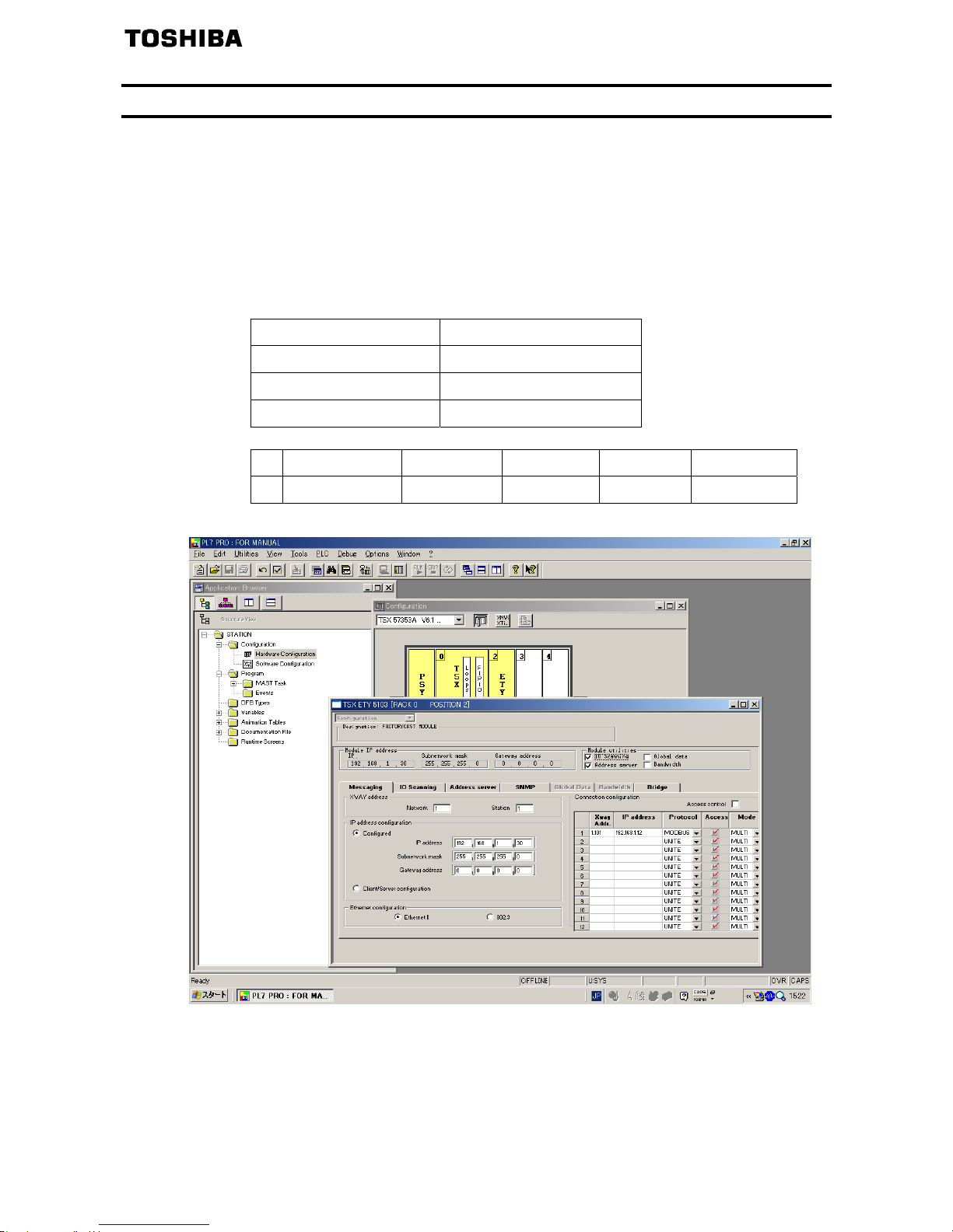
E6581741
- 75 -
10.3. Configuring Modbus messaging
To use Modbus messaging in PL7, the “IP address”, “Subnet mask” and “Gateway
address” parameters must be configured in the “Messaging” tab in the PLC Ethernet
module configuration screen.
Data entered in the “Connection configuration” box is used to manage the PLC Modbus
messaging service, but has no effect on IO Scanning which is an independent service.
Example:
PLC IP address 192.168.1.30
Subnet mask 255.255.255.0
Gateway address 0.0.0.0
Drive IP address 192.168.1.12
Xway address IP address Protocol Access Mode
1
1,101 192.168.1.12 MODBUS
;
MULTI

E6581741
- 76 -
10.4. Configuring periodic variables
This window is used to configure the IO Scanning function, described in the IO Scanning
Service section on page 72.
Example:
•The periodic variables of the drive at IP address 192.168.1.12 are associated with PLC
data words.
•The drive periodic output variables (control) are associated with the 32 words (WR
count) starting at PLC address %MW550 (Write Ref.).
•The drive periodic input variables (monitoring) are associated with the 32 words (RD
count) starting at PLC address %MW500 (Read Ref.).
The addresses for the PLC %MW words correspond to the configuration in the previous example.
PLC
address
Periodic output variable
(default assignment)
Configurable
%MW 550 Reserved No
%MW 551 Scanner write word 1 Yes (c001)
%MW 552 Scanner write word 2 Yes (c002)
%MW 553 Scanner write word 3 Yes (c003)
%MW 554 Scanner write word 4 Yes (c004)
%MW 555 Scanner write word 5 Yes (c005)
%MW 556 Scanner write word 6 Yes (c006)
%MW 557
to
%MW 581
Reserved No
PLC
address
Periodic output variable
(default assignment)
Configurable
%MW 500 Reserved No
%MW 501 Scanner read word 1 Yes (c021)
%MW 502 Scanner read word 2 Yes (c022)
%MW 503 Scanner read word 3 Yes (c023)
%MW 504 Scanner read word 4 Yes (c024)
%MW 505 Scanner read word 5 Yes (c025)
%MW 506 Scanner read word 6 Yes (c026)
%MW 507
to
%MW 531
Reserved No

E6581741
- 77 -
11. Command & Setpoint selection (Local/Remote)
Indication to display Local/Remote mode is on the inverter unit (Refer to the inverter
instruction manual for details). EtherNet/IP™ - Modbus
®
TCP option command and
setpoint are activated on Remote mode.
Inverters have some switches to select the command and setpoint location. Following
figure shows the diagram. Refer to the inverter instruction manual for the parameter in
detail.
Command
Set poi nt
Con trol term inal
Operation panel
Se rial Com m. (R S485)
Serial Comm. (
CANopen
®
)
Network option
(EtherNet/IP-Modbus TCP)
Operation panel
:
Network option
(EtherNet/IP-Modbus TCP)
Terminal board VIC
:
Puls e train in put
Operation pane l
RUN/STOP
“LOC ” key
Remote panel (RKP007Z) or
EASY ke
y (
f750=2
)
cmod
fmod
0
:
7
8
:
11
1
0
1
0
Input terminal function
48 (SCLC)
Forced local from comm..
f207
Selection
0
1
0
1
REM
LOC
REM
LOC
0
1
2
3
4
Input terminal function
104 (FCHG)
Setp oi nt se le ctio n swi tc h
Input terminal function
108 (CM T B )
Command from terminal
Contr ol
Te rm i na l
RS485
(fa01)
RS485
(fa00)
Operation panel
Dial (fc)

E6581741
- 78 -
<Example of setting>
The example below shows how to configure the local/remote operation.
F terminal ............... Operating command
R terminal ............... EtherNet/IP-Modbus TCP local/remote
(Terminal in this example) switching
VIA terminal ........... Operation frequency command
<Wiring>
VF-MB1
F
R
CC
PP
VIA
Variable resistor for adjustment
10k ohm
EtherNet/IP-Modbus TCP
/local Switch
Operation command
SINK
SW1*
SOURCE
CC
PLC
<Parameter setting>
cmod
(Command mode selection) = 0 (Terminal board)
fmod
(Frequency setting mode selection 1) = 1 (VIA)
f112
(Input terminal selection 2 (R)) = 48 (Remote/Local control)
<Operation>
R-CC terminal open: VF-MB1 is controlled as a slave device of the EtherNet/IP™ -
Modbus
®
TCP.
R-CC terminal closed:
F-CC terminal short to RUN
F-CC terminal open to STOP
Output frequency is set up by the VIA signal input.
(Note)
When the local(HAND) / remote key (f750=2) is chosen as EASY key selection and
the EASY key lamp of an inverter front panel is on, priority is most given to operation by
a panel. (Refer to the inverter instruction manual for details).

E6581741
- 79 -
12. Unusual diagnosis
12.1. Option error
An error message is displayed when the hardware error or software error or lose of
connection of wire is occurred.
When an option and a combination of the inverter are bad, it is displayed.
■Display of trip information
e-23 (Error code : 55) : Optional unit fault 2
12.2. Disconnection error of network cable
When network trouble occurred by disconnection etc, the inverter does emergency stop
with the following indication when the network disconnection detection (c100, c523)
is set, and it was set in (c101=4).
■Display of trip information
err8 (Error code: 27): Optional unit fault 1 (Communication error)

E6581741
- 80 -
13. WebServer
The option has webserver function. Writing and reading the drive's parameter and the
communication can be monitored by using this function through web network.
The chapter describes the function of the integrated webserver of the EtherNet/IP™ -
Modbus
®
TCP module.
13.1. Access to the webserver
This web server can be accessed by the navigators listed below:
Microsoft
®
Internet Explorer – Version 5.0 or greater
The navigator must support Java™ Virtual Machine because the factory loaded web
server uses applets.
NOTE: As a TOSHIBA product, The EtherNet/IP™ option module uses internally Modbus
®
TCP
for the webserver. (The Modbus
®
TCP port is not accessible.)
Startup the web browser and input IP address of the drive as the homepage address.
From your web browser, default http password and login are “USER”.
The drive IP address

E6581741
- 81 -
From the TOSVERT home page, you can access to 3 main menus:
Monitoring
Network setup
Diagnostics
13.2. Web pages structure
Each web page uses the same structure. Each main menu, "Monitoring", "Network
Setup" and "Diagnostics" contains each own sub menu. This last one is displayed on the
left side of web page.
The toggle button shows or hides the left sided menu.

E6581741
- 82 -
13.3. Drive monitor (Main menu: Monitoring)
The state of the drive can be confirmed on this page.

E6581741
- 83 -
13.4. Drive parameters (Main menu: Monitoring)
The parameters of the drive can be set on this page.
The left column is used to select a modify group (or list) of parameters. The right column
displays the parameters, its Modbus address and its current value.
Set the parameters
When parameters of the drive are modified from the webserver, you need to input the
PASSWORD. (The default password is "USER.")
It is necessary to be monitoring it to change the parameter.
Start the monitor

E6581741
- 84 -
Input the write value to popup window.

E6581741
- 85 -
13.5. Network parameters (Main menu: Network Setup)
The network parameters of the drive can be confirmed on this page.
When network parameters of the drive are modified from the webserver, you need to
input the PASSWORD. (The default password is "USER.")
13.6. Modbus scanner (Main menu: Network Setup)
The I/O scanner of the Modbus® TCP protocol can be set on this page.
When I/O scanner of the Modbus
®
TCP protocol are modified from the webserver, input
the PASSWORD. (The default password is "USER.")

E6581741
- 86 -
13.7. EthIP scanner (Main menu: Network Setup)
The I/O scanner of the EtherNet/IP protocol can be set on this page.
When I/O scanner of the Modbus
®
TCP protocol are modified from the webserver, input
the PASSWORD. (The default password is "USER.")
Select the I/O scan parameters in "Config" column.

E6581741
- 87 -
13.8. Administration (Main menu: Network Setup)
The "web read password" and "web write password" of the webserver can be modify on
this page.

E6581741
- 88 -
13.9. TCP/IP statistics (Main menu: Diagnostics)
You can check TCP/IP status on this page.
- 88E-
 Loading...